WO2012132422A1 - 非ニュートン流体の粘度調整方法 - Google Patents
非ニュートン流体の粘度調整方法 Download PDFInfo
- Publication number
- WO2012132422A1 WO2012132422A1 PCT/JP2012/002140 JP2012002140W WO2012132422A1 WO 2012132422 A1 WO2012132422 A1 WO 2012132422A1 JP 2012002140 W JP2012002140 W JP 2012002140W WO 2012132422 A1 WO2012132422 A1 WO 2012132422A1
- Authority
- WO
- WIPO (PCT)
- Prior art keywords
- viscosity
- newtonian fluid
- slurry
- storage tank
- heat exchanger
- Prior art date
- Legal status (The legal status is an assumption and is not a legal conclusion. Google has not performed a legal analysis and makes no representation as to the accuracy of the status listed.)
- Ceased
Links
Images




Classifications
-
- G—PHYSICS
- G01—MEASURING; TESTING
- G01N—INVESTIGATING OR ANALYSING MATERIALS BY DETERMINING THEIR CHEMICAL OR PHYSICAL PROPERTIES
- G01N11/00—Investigating flow properties of materials, e.g. viscosity, plasticity; Analysing materials by determining flow properties
- G01N11/10—Investigating flow properties of materials, e.g. viscosity, plasticity; Analysing materials by determining flow properties by moving a body within the material
- G01N11/14—Investigating flow properties of materials, e.g. viscosity, plasticity; Analysing materials by determining flow properties by moving a body within the material by using rotary bodies, e.g. vane
-
- G—PHYSICS
- G01—MEASURING; TESTING
- G01N—INVESTIGATING OR ANALYSING MATERIALS BY DETERMINING THEIR CHEMICAL OR PHYSICAL PROPERTIES
- G01N11/00—Investigating flow properties of materials, e.g. viscosity, plasticity; Analysing materials by determining flow properties
- G01N2011/0006—Calibrating, controlling or cleaning viscometers
- G01N2011/0013—Temperature compensation
-
- G—PHYSICS
- G01—MEASURING; TESTING
- G01N—INVESTIGATING OR ANALYSING MATERIALS BY DETERMINING THEIR CHEMICAL OR PHYSICAL PROPERTIES
- G01N11/00—Investigating flow properties of materials, e.g. viscosity, plasticity; Analysing materials by determining flow properties
- G01N2011/0026—Investigating specific flow properties of non-Newtonian fluids
Definitions
- the present invention relates to a method for adjusting the viscosity of a non-Newtonian fluid.
- Patent Document 1 discloses an ultrasonic viscosity measuring method.
- a sound wave is applied to a viscous fluid, and the sound velocity and absorption value of the sound wave in the viscous liquid are obtained.
- a viscosity is calculated
- a capillary method, a falling ball method, a rotation method, and the like are known.
- the viscosity manager adds a solvent to reduce the measured viscosity to the set viscosity.
- the viscosity characteristic (solid line) of the non-Newtonian fluid changes to another viscosity characteristic (broken line) (arrow in FIG. 7), and viscosity adjustment is erroneously performed. Therefore, highly accurate viscosity adjustment becomes difficult.
- the present invention has been made in view of such points, and an object thereof is to perform highly accurate viscosity adjustment for a non-Newtonian fluid.
- the first invention is directed to a method for adjusting the viscosity of a non-Newtonian fluid stirred in a storage tank (22). And this invention detects the temperature, flow velocity and viscosity of the non-Newtonian fluid in the storage tank (22) and the detection based on the correlation of the temperature, flow velocity and viscosity of the non-Newtonian fluid derived in advance. And a step of adding the non-Newtonian fluid solvent into the storage tank (22) so that the corrected viscosity becomes a set value.
- the non-Newtonian fluid is agitated to suppress precipitation.
- the non-Newtonian fluid is likely to change its flow rate by being stirred. Therefore, the detected viscosity of the non-Newtonian fluid is likely to change.
- the viscosity adjusting method of the present invention first, the temperature, flow rate and viscosity of a non-Newtonian fluid to be stirred are detected. Next, the detected viscosity is corrected based on the correlation (viscosity characteristics) of the temperature, flow rate and viscosity of the non-Newtonian fluid prepared in advance. For example, when the corrected viscosity is higher than the set value, the solvent is added into the storage tank (22) so that the corrected viscosity is reduced to the set value.
- the stirring operation of the non-Newtonian fluid is controlled so that the flow velocity of the non-Newtonian fluid is within a predetermined range in the storage tank (22).
- the predetermined range is set to a range in which the non-Newtonian flowmeter can be substantially measured. This improves the detection accuracy of the flow velocity.
- the non-Newtonian fluid in the storage tank (22) flows out while being stirred.
- the flow velocity of the non-Newtonian fluid in the storage tank (22) is likely to change due to the outflow operation. Even in this case, the detected viscosity is corrected and the viscosity is adjusted so that the corrected viscosity becomes a set value.
- the non-Newtonian fluid in the storage tank (22) is pumped out by the pump (23) while being stirred.
- the non-Newtonian fluid is pumped from the storage tank (22) by the pump (23), and this pumping operation makes it easy to change the flow rate of the non-Newtonian fluid in the storage tank (22).
- the temperature of the non-Newtonian fluid in the storage tank (22) is controlled to be constant.
- the temperature of the non-Newtonian fluid in the storage tank (22) is constant, so that the detected viscosity changes substantially due to only the flow velocity.
- the non-Newtonian fluid is a slurry whose solvent is mainly alcohol.
- the non-Newtonian fluid is a slurry whose main component is alcohol, so the viscosity of the non-Newtonian fluid itself is likely to change. Alcohol tends to volatilize, and as the alcohol volatilizes in the non-Newtonian fluid, the proportion of the solvent decreases and the viscosity increases.
- the detected viscosity is corrected based on the correlation of the temperature, flow velocity, and viscosity of the non-Newtonian fluid derived in advance, and the storage tank ( 22)
- the solvent of non-Newtonian fluid was added into the inside. Therefore, it can be ascertained that the viscosity characteristics of the non-Newtonian fluid have changed. Thereby, highly accurate viscosity adjustment can be performed about a non-Newtonian fluid.
- the non-Newtonian fluid is agitated and controlled so that the flow velocity of the non-Newtonian fluid is within a predetermined range, for example, the predetermined range can be substantially measured by the non-Newtonian fluid velocity meter.
- the detection accuracy of the flow velocity can be improved.
- the correction accuracy of the viscosity of the non-Newtonian fluid is improved, so that the viscosity can be adjusted with higher accuracy.
- the present invention can reliably grasp that the viscosity characteristics have changed.
- the detected viscosity of the non-Newtonian fluid changes due mainly to only the flow velocity, so that changes in viscosity characteristics can be easily grasped.
- the solvent of the non-Newtonian fluid contains alcohol as a main component, the viscosity is likely to change, but even in such a case, the change in the viscosity characteristics can be reliably grasped.
- FIG. 1 is a piping system diagram showing the configuration of the refrigerant circuit of the embodiment, in which (A) shows the operation during the first operation, and (B) shows the operation during the second operation. is there.
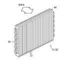
- FIG. 2 is a schematic perspective view of the adsorption heat exchanger.
- Drawing 3 is a schematic structure figure showing a slurry supply device of an embodiment.
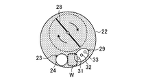
- FIG. 4 is a cross-sectional view showing the inside of the storage tank.
- FIG. 5 is a diagram showing the blending ratio of the slurry.
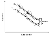
- FIG. 6 is a graph showing the relationship between the flow rate of the slurry and the viscosity.
- FIG. 7 is a graph for explaining the viscosity adjustment with respect to the flow rate of the slurry.
- the viscosity adjusting method of this embodiment is a method for adjusting the viscosity of the slurry applied to the adsorption heat exchanger (51, 52).
- the slurry is a non-Newtonian fluid.
- the adsorption heat exchanger (51, 52) is mounted on a humidity control device (10) that performs indoor humidity control.
- the humidity control apparatus (10) is configured to be capable of a dehumidifying operation for supplying dehumidified air to the room and a humidifying operation for supplying humidified air to the room.
- the humidity control apparatus (10) includes a refrigerant circuit (50).
- the refrigerant circuit (50) includes a first adsorption heat exchanger (51), a second adsorption heat exchanger (52), a compressor (53), a four-way switching valve (54), and an electric motor It is a closed circuit provided with an expansion valve (55).
- the refrigerant circuit (50) performs a vapor compression refrigeration cycle by circulating the filled refrigerant.
- the compressor (53) has its discharge side connected to the first port of the four-way switching valve (54) and its suction side connected to the second port of the four-way switching valve (54).
- One end of the first adsorption heat exchanger (51) is connected to the third port of the four-way switching valve (54).
- the other end of the first adsorption heat exchanger (51) is connected to one end of the second adsorption heat exchanger (52) via the electric expansion valve (55).
- the other end of the second adsorption heat exchanger (52) is connected to the fourth port of the four-way switching valve (54).
- the four-way switching valve (54) includes a first state (state shown in FIG. 1A) in which the first port and the third port communicate with each other, and the second port and the fourth port communicate with each other. These ports can be switched to a second state (the state shown in FIG. 1B) in which the second port and the fourth port communicate with each other and the second port and the third port communicate with each other.
- the first adsorption heat exchanger (51) and the second adsorption heat exchanger (52) are adsorbed by applying slurry mixed with an adsorbent on the surface of the heat exchanger body (40).
- a layer is formed.
- the heat exchanger body (40) is formed of a cross fin type fin-and-tube type heat exchanger.
- the heat exchanger body (40) includes an aluminum fin (57) and a copper heat transfer tube (58) penetrating the fin (57).
- the plurality of fins (57) are formed in an elongated rectangular plate shape, and are arranged in parallel in the extending direction of the heat transfer tube (58) at a constant interval.
- each fin (57) is preferably in the range of 1.2 mm to 2.2 mm, and more preferably in the range of 1.4 mm to 1.6 mm.
- the diameter of the heat transfer tube (58) is preferably in the range of 7.0 mm to 9.5 mm.
- the number of rows in the width direction of the fins (57) of the heat transfer tubes (58) is preferably in a range from 2 rows to 4 rows.
- the number of stages of the fins (57) in the longitudinal direction of the heat transfer tube (58) is preferably in the range of 10 to 20 stages.
- the fin (57) is a so-called plate fin having a rectangular plate shape.
- the fin (57) is a so-called waffle fin having a gentle wave shape in the cross-sectional shape in the width direction. May be.
- ⁇ Operation of humidity control device The operation of the humidity control apparatus (10) described above will be described.
- a dehumidifying operation and a humidifying operation are performed.
- the humidity control device (10) adjusts the taken outdoor air (OA) and supplies it to the room as supply air (SA).
- SA room as supply air
- RA taken indoor air
- EA discharge outside as air
- the humidity control apparatus (10) alternately repeats the first operation and the second operation at predetermined time intervals (for example, every 3 minutes) during both the dehumidifying operation and the humidifying operation.
- the humidity controller (10) takes in outdoor air (OA) as the first air and indoor air (RA) as the second air during the dehumidifying operation.
- the humidity control apparatus (10) takes in indoor air (RA) as the first air and outdoor air (OA) as the second air during the humidifying operation.
- the first operation will be described.
- the second air is sent to the first adsorption heat exchanger (51) and the first air is sent to the second adsorption heat exchanger (52).
- a regeneration operation for the first adsorption heat exchanger (51) and an adsorption operation for the second adsorption heat exchanger (52) are performed.
- the four-way switching valve (54) is set to the first state.
- the compressor (53) When the compressor (53) is operated, the refrigerant circulates in the refrigerant circuit (50). Specifically, the refrigerant discharged from the compressor (53) dissipates heat in the first adsorption heat exchanger (51) and condenses. The refrigerant condensed in the first adsorption heat exchanger (51) is decompressed when passing through the electric expansion valve (55), and then absorbs heat in the second adsorption heat exchanger (52) and evaporates. The refrigerant evaporated in the second adsorption heat exchanger (52) is sucked into the compressor (53), compressed, and discharged again from the compressor (53).
- the first adsorption heat exchanger (51) serves as a condenser and the second adsorption heat exchanger (52) serves as an evaporator.
- the first adsorption heat exchanger (51) the adsorbent on the surface of the fin (57) is heated by the refrigerant in the heat transfer tube (58), and moisture desorbed from the heated adsorbent is given to the second air.
- the second adsorption heat exchanger (52) moisture in the first air is adsorbed by the adsorbent on the surface of the fin (57), and the generated adsorption heat is absorbed by the refrigerant in the heat transfer tube (58).
- the first air dehumidified by the second adsorption heat exchanger (52) is supplied into the room, and the moisture desorbed from the first adsorption heat exchanger (51) is combined with the second air. It is discharged outside the room.
- the second air humidified by the first adsorption heat exchanger (51) is supplied into the room, and the first air deprived of moisture by the second adsorption heat exchanger (52) It is discharged outside the room.
- the second operation will be described.
- the first air is sent to the first adsorption heat exchanger (51) and the second air is sent to the second adsorption heat exchanger (52).
- a regeneration operation for the second adsorption heat exchanger (52) and an adsorption operation for the first adsorption heat exchanger (51) are performed.
- the four-way switching valve (54) is set to the second state.
- the compressor (53) When the compressor (53) is operated, the refrigerant circulates in the refrigerant circuit (50). Specifically, the refrigerant discharged from the compressor (53) dissipates heat and condenses in the second adsorption heat exchanger (52). The refrigerant condensed in the second adsorption heat exchanger (52) is depressurized when passing through the electric expansion valve (55), and thereafter absorbs heat in the first adsorption heat exchanger (51) and evaporates. The refrigerant evaporated in the first adsorption heat exchanger (51) is sucked into the compressor (53), compressed, and discharged again from the compressor (53).
- the second adsorption heat exchanger (52) serves as a condenser
- the first adsorption heat exchanger (51) serves as an evaporator.
- the second adsorption heat exchanger (52) the adsorbent on the surface of the fin (57) is heated by the refrigerant in the heat transfer tube (58), and moisture desorbed from the heated adsorbent is given to the second air.
- the first adsorption heat exchanger (51) moisture in the first air is adsorbed by the adsorbent on the surface of the fin (57), and the generated adsorption heat is absorbed by the refrigerant in the heat transfer tube (58).
- the first air dehumidified by the first adsorption heat exchanger (51) is supplied into the room, and the moisture desorbed from the second adsorption heat exchanger (52) is combined with the second air. It is discharged outside the room.
- the second air humidified by the second adsorption heat exchanger (52) is supplied into the room, and the first air deprived of moisture by the first adsorption heat exchanger (51) is supplied. It is discharged outside the room.
- the slurry supply device (20) will be described with reference to FIG. 3 and FIG.
- This slurry supply apparatus (20) supplies a slurry to the coating treatment part (1) which applies a slurry to the adsorption heat exchanger (51, 52) described above.
- the slurry supply device (20) includes a temperature adjustment water tank (21), a storage tank (22), a supply path (25), and a recovery path (26). Slurry is stored in the storage tank (22). Water is stored in the temperature-controlled water tank (21), and the storage tank (22) is immersed in the water. The temperature of the water in the temperature adjustment tank (21) is adjusted by temperature adjustment means (not shown).
- the storage tank (22) is provided with a pump (23), a stirrer (27), and a sensor unit (29).
- a pump (23) the suction part (24) is immersed in the slurry in a storage tank (22), and pumps up a slurry from a suction part (24).
- a supply path (25) is connected to the discharge section (not shown) of the pump (23) and the coating processing section (1).
- a collection path (26) is connected to the storage tank (22) and the coating treatment section (1).
- the supply path (25) is a path through which the slurry pumped up by the pump (23) is supplied to the coating processing section (1).
- the collection path (26) is a path through which the slurry used in the coating treatment unit (1) returns to the storage tank (22).
- the stirrer (27) stirs the slurry so that the slurry in the storage tank (22) does not settle. Specifically, in the stirrer (27), the slurry is stirred by rotating the stirring blade (28).
- the sensor unit (29) is immersed in the slurry in the storage tank (22), and the viscosity sensor (31), temperature sensor (32), and flow rate sensor (for detecting the viscosity, temperature, and flow rate of the slurry, respectively). 33).
- the flow velocity sensor (33) outputs the flow velocity as a voltage value V. The higher the flow rate, the higher the output voltage value.
- the slurry supply device (20) includes a slurry viscosity calculation unit (35) and a control unit (36) of the stirrer (27).
- the viscosity calculator (35) corrects the viscosity of the slurry based on the temperature and flow rate of the slurry.
- the controller (36) controls the rotation speed of the agitator (27) so that the flow rate of the slurry in the storage tank (22) is within a predetermined range. Details of the correcting operation and the viscosity adjusting method by the viscosity calculating section (35) will be described later.
- the slurry (60) according to the present embodiment is 100 parts by mass of the adsorbent (61), 30 parts by mass of the binder (62), 30 parts by mass of water, and 220 parts by mass of alcohol. . That is, 30 parts by mass of water and 220 parts by mass of alcohol constitute the solvent (63).
- the binder (62) and water are those constituting one aqueous resin (64).
- the aqueous resin (64) is sufficient if the binder (62) as a solid content is 45% by mass or more (moisture of 45% by mass or less). In short, the concentration of the binder (62) is high. I just need it.
- the alcohol is an organic solvent, and various alcohols can be used, but industrial alcohols mainly composed of ethanol and added with a plurality of other alcohols are preferable. Specifically, the alcohol is composed of 85.5% ethanol, 9.8% normal propyl alcohol, 4.8% isopropyl alcohol, and 0.2% water.
- the adsorbent (61), the binder (62), and the solvent (63) are mixed and sufficiently stirred to disperse the adsorbent (61) and the binder (62) in the solvent (63).
- the adsorbent (61) forms a three-dimensional structure by cross-linking a plurality of polymer main chains having hydrophilic groups.
- the adsorbent (61) performs both adsorption and absorption of water vapor when absorbing moisture from the air.
- the average particle diameter of the adsorbent (61) is, for example, about 50 ⁇ m.
- the application state of the slurry (60) greatly depends on the viscosity of the slurry (60).
- the detected viscosity viscosity detected by the viscosity sensor (31)
- the flow rate of the slurry (60) is likely to change due to uneven stirring.
- the slurry (60) of the present embodiment alcohol is blended as described above. Since alcohol is highly volatile, the alcohol volatilizes over time. Then, since the ratio of the solvent (63) in the slurry (60) decreases, the viscosity of the slurry (60) gradually increases. That is, the viscosity of the slurry (60) is more likely to change. Other factors that cause the flow rate of the slurry (60) to change include the amount of slurry (60) stored in the storage tank (22), the distance between the stirring blade (28) and the flow rate sensor (33), and the like. From the above, it is necessary to manage and adjust the viscosity of the slurry (60) in the storage tank (22).
- the rotational speed of the stirrer (27) (stirrer (27) so that the flow rate of the slurry (60) in the storage tank (22) is always within a predetermined range.
- the stirring operation is controlled.
- the predetermined range is set to a substantially measurable range (measurement range) of the flow rate sensor (33). By doing so, it is possible to reliably and highly accurately detect the flow rate of the changing slurry (60).
- the control unit (36) adjusts the rotational speed of the agitator (27) so that the detection value of the flow velocity sensor (33) is within the predetermined range.
- the stirrer (27) is controlled within a range not impairing the stirring function for the slurry (60).
- the temperature, flow rate and viscosity of the slurry (60) in the storage tank (22) are detected by the sensor unit (29) in the state where the flow rate of the slurry (60) is within a predetermined range (detection step). .
- the detected temperature, flow rate, and viscosity values are input to the viscosity calculation unit (35).
- the temperature adjustment water tank (21) of the present embodiment is controlled so that the water temperature is constant. Therefore, the temperature of the slurry (60) in the storage tank (22) is substantially constant.
- viscosity calculation unit (35) correlation data (hereinafter referred to as viscosity characteristics) of the temperature, flow rate and viscosity of the slurry (60) derived in advance is input.
- a viscosity characteristic for example, Y in FIG. 6 that is a relationship between the flow rate and the viscosity at the constant temperature is input.
- the detection viscosity calculation section (35) when the detection temperature, the detection flow velocity and the detection viscosity are input from the sensor unit (29), the detection viscosity is corrected based on the previously input viscosity characteristics (correction step). That is, a new viscosity characteristic (X in the figure) different from the previously inputted viscosity characteristic (Y in the figure) is derived. In short, in this case, the viscosity of the slurry (60) is high.
- the amount of the solvent (63) added to the storage tank (22) is calculated based on the difference between the corrected detected viscosity and the set viscosity. That is, the amount of the solvent (63) necessary for reducing the corrected detected viscosity to the set viscosity is calculated. Then, a necessary amount of the solvent (63) is added to the storage tank (22) (solvent addition step). Thereby, the viscosity of the slurry (60) is adjusted to the set viscosity. That is, as shown in FIG. 6, the addition of the solvent (63) changes the viscosity characteristic X to the viscosity characteristic Y.
- the detected viscosity is corrected based on the correlation of the temperature, flow rate and viscosity of the slurry (60) derived in advance, and the corrected viscosity becomes the set value into the storage tank (22).
- the solvent of slurry (60) was added. Therefore, it can be surely grasped that the viscosity characteristic of the slurry (60) has changed. Thereby, highly accurate viscosity adjustment can be performed about a slurry (60).
- the detected viscosity of the slurry (60) changes mainly due to only the flow velocity, it is possible to easily grasp the change in the viscosity characteristics.
- the viscosity of the slurry (60) is easily changed because the solvent is mainly composed of alcohol. Even in such a case, the change in the viscosity characteristics can be reliably grasped. .
- the stirrer (27) is controlled so that the flow rate of the slurry (60) is within a range (measurement range) that can be substantially measured by the flow rate sensor (33). Therefore, the detection accuracy of the flow rate of the slurry (60) can be improved. Thereby, since the correction
- the present invention is useful for a method for adjusting the viscosity of a non-Newtonian fluid.
Landscapes
- Physics & Mathematics (AREA)
- Health & Medical Sciences (AREA)
- Life Sciences & Earth Sciences (AREA)
- Chemical & Material Sciences (AREA)
- Analytical Chemistry (AREA)
- Biochemistry (AREA)
- General Health & Medical Sciences (AREA)
- General Physics & Mathematics (AREA)
- Immunology (AREA)
- Pathology (AREA)
- Central Air Conditioning (AREA)
Abstract
貯留槽(22)内のスラリーの温度、流速および粘度を検出する工程と、予め導出したスラリーの温度、流速および粘度の相関に基づいて、検出した粘度を補正する工程と、補正した粘度が設定値になるように、貯留槽(22)内へスラリーの溶媒を加える工程とを備えている。
Description
本発明は、非ニュートン流体の粘度調整方法に関する。
従来より、非ニュートン流体の粘度を測定する方法が種々知られている。例えば、特許文献1には、超音波式粘度測定方法が開示されている。この粘度測定方法では、粘性流体に音波を付与して、粘性液体中の音波の音速と吸収値を求める。そして、求めた音速および吸収値に基づいて粘度が求められる。その他の粘度測定方法として、毛細管法や落下球法、回転法等が知られている。
ところで、非ニュートン流体の場合、上述した粘度測定方法で測定した測定粘度が流速によって変化するため、高精度な粘度管理を行うことが困難であった。例えば、図7に示すように、実線で示した粘度特性を有する非ニュートン流体の場合、流速v2では測定粘度が設定粘度と同じ値になる。ここで、上記非ニュートン流体の流速がv2からv1に低下すると、測定粘度は設定粘度よりも高い値となる。この状態では、上記非ニュートン流体の粘度特性(実線)は変化していない。ところが、粘度管理者は、測定粘度を設定粘度まで低下させようとして、溶媒を加えることとなる。その結果、上記非ニュートン流体の粘度特性(実線)が別の粘度特性(破線)へと変化してしまい(図7の矢印)、誤って粘度調整が行われてしまう。よって、高精度な粘度調整が困難となる。
本発明は、かかる点に鑑みてなされたものであり、その目的は、非ニュートン流体について高精度な粘度調整を行うことにある。
第1の発明は、貯留槽(22)内で撹拌される非ニュートン流体の粘度調整方法を対象としている。そして、本発明は、上記貯留槽(22)内の非ニュートン流体の温度、流速および粘度を検出する工程と、予め導出した上記非ニュートン流体の温度、流速および粘度の相関に基づいて、上記検出した粘度を補正する工程と、上記補正した粘度が設定値になるように、上記貯留槽(22)内へ上記非ニュートン流体の溶媒を加える工程とを備えている。
上記第1の発明において、非ニュートン流体は撹拌されることによって沈殿が抑制される。一方、非ニュートン流体は、撹拌されることによって、流速が変化しやすい。そのため、非ニュートン流体の検出粘度も変化しやすい。本発明の粘度調整方法では、先ず、撹拌される非ニュートン流体の温度、流速および粘度が検出される。次に、予め用意された非ニュートン流体の温度、流速および粘度の相関(粘度特性)に基づいて、検出した粘度が補正される。そして、例えば補正された粘度が設定値よりも高い場合、補正された粘度が設定値まで低下するように、貯留槽(22)内に溶媒が加えられる。
第2の発明は、上記第1の発明において、上記貯留槽(22)内では、非ニュートン流体の流速が所定の範囲内となるように非ニュートン流体の撹拌動作が制御される。
上記第2の発明では、常に非ニュートン流体の流速が所定の範囲内となるように制御されるため、例えば、上記所定の範囲を非ニュートン流体の流速計の実質測定可能な範囲に設定することによって、流速の検出精度が向上する。
第3の発明は、上記第1の発明において、上記貯留槽(22)内の非ニュートン流体は、撹拌されながら外部へ流出する。
上記第3の発明では、貯留槽(22)から非ニュートン流体が流出するので、その流出動作によって貯留槽(22)内の非ニュートン流体の流速が変化しやすくなる。この場合でも、検出された粘度が補正されて、その補正された粘度が設定値になるように粘度調整される。
第4の発明は、上記第3の発明において、上記貯留槽(22)内の非ニュートン流体は、撹拌されながらポンプ(23)によって汲み出される。
上記第4の発明では、貯留槽(22)から非ニュートン流体がポンプ(23)によって汲み上げられるため、この汲み上げ動作によって貯留槽(22)内の非ニュートン流体の流速が変化しやすくなる。
第5の発明は、上記第1乃至第4の何れか1の発明において、上記貯留槽(22)内の非ニュートン流体は、その温度が一定となるように制御される。
上記第5の発明では、貯留槽(22)内の非ニュートン流体の温度が一定となるため、概ね流速のみが起因して検出粘度が変化する。
第6の発明は、上記第1乃至第5の何れか1の発明において、上記非ニュートン流体は、溶媒がアルコールを主成分とするスラリーである。
上記第6の発明では、非ニュートン流体は溶媒がアルコールを主成分とするスラリーであるため、非ニュートン流体自体の粘度が変化しやすい。アルコールは揮発しやすいところ、非ニュートン流体においてアルコールが揮発していくことにより溶媒の割合が低下して粘度が高くなる。
以上説明したように、本発明によれば、予め導出した非ニュートン流体の温度、流速および粘度の相関に基づいて、検出した粘度を補正し、補正した粘度が設定値になるように貯留槽(22)内へ非ニュートン流体の溶媒を加えるようにした。そのため、非ニュートン流体の粘度特性が変化したことを確実に把握することができる。これにより、非ニュートン流体について、高精度な粘度調整を行うことができる。
第2の発明によれば、非ニュートン流体の流速が所定の範囲内となるように非ニュートン流体が撹拌制御されるため、例えば、上記所定の範囲を、非ニュートン流体の流速計の実質測定可能な範囲に設定することによって、流速の検出精度を向上させることができる。これにより、非ニュートン流体の粘度の補正精度が向上するので、より高精度な粘度調整を行うことが可能である。
第3の発明では貯留槽(22)内の非ニュートン流体が撹拌されながら外部へ流出するため、第4の発明では撹拌されながらポンプ(23)によって吸引されるため、非ニュートン流体の流速が変化して粘度が変化しやすくなる。ところが、このような条件下であっても、本発明では粘度特性が変化したことを確実に把握することができる。
第5の発明によれば、概ね流速のみが起因して非ニュートン流体の検出粘度が変化するため、粘度特性の変化を容易に把握することができる。
第6の発明によれば、非ニュートン流体の溶媒がアルコールを主成分としていることから粘度が変化しやすくなるが、このような場合でも、確実に粘度特性の変化を把握することができる。
以下、本発明の実施形態を図面に基づいて説明する。なお、以下の実施形態は、本質的に好ましい例示であって、本発明、その適用物、あるいはその用途の範囲を制限することを意図するものではない。
本実施形態の粘度調整方法は、吸着熱交換器(51,52)に塗布するスラリーの粘度調整方法である。スラリーは、非ニュートン流体である。吸着熱交換器(51,52)は、室内の調湿を行う調湿装置(10)に搭載されるものである。この調湿装置(10)は、除湿した空気を室内へ供給する除湿運転と、加湿した空気を室内へ供給する加湿運転とが可能に構成されている。
〈調湿装置の構成〉
調湿装置(10)は、冷媒回路(50)を備えている。図1に示すように、この冷媒回路(50)は、第1吸着熱交換器(51)、第2吸着熱交換器(52)、圧縮機(53)、四方切換弁(54)、及び電動膨張弁(55)が設けられた閉回路である。この冷媒回路(50)は、充填された冷媒を循環させることによって、蒸気圧縮冷凍サイクルを行う。
調湿装置(10)は、冷媒回路(50)を備えている。図1に示すように、この冷媒回路(50)は、第1吸着熱交換器(51)、第2吸着熱交換器(52)、圧縮機(53)、四方切換弁(54)、及び電動膨張弁(55)が設けられた閉回路である。この冷媒回路(50)は、充填された冷媒を循環させることによって、蒸気圧縮冷凍サイクルを行う。
冷媒回路(50)において、圧縮機(53)は、その吐出側が四方切換弁(54)の第1のポートに、その吸入側が四方切換弁(54)の第2のポートにそれぞれ接続されている。第1吸着熱交換器(51)の一端は、四方切換弁(54)の第3のポートに接続されている。第1吸着熱交換器(51)の他端は、電動膨張弁(55)を介して第2吸着熱交換器(52)の一端に接続されている。第2吸着熱交換器(52)の他端は、四方切換弁(54)の第4のポートに接続されている。
四方切換弁(54)は、第1のポートと第3のポートが連通して第2のポートと第4のポートが連通する第1状態(図1(A)に示す状態)と、第1のポートと第4のポートが連通して第2のポートと第3のポートが連通する第2状態(図1(B)に示す状態)とに切り換え可能となっている。
〈吸着熱交換器の構成〉
図2に示すように、第1吸着熱交換器(51)及び第2吸着熱交換器(52)は、熱交換器本体(40)の表面に吸着剤が配合されたスラリーを塗布して吸着層を形成したものである。熱交換器本体(40)は、クロスフィン型のフィン・アンド・チューブ型の熱交換器で構成されている。これら熱交換器本体(40)は、アルミニウム製のフィン(57)と、このフィン(57)を貫通する銅製の伝熱管(58)とを備えている。複数のフィン(57)は、細長の長方形板状に形成され、伝熱管(58)の伸長方向に一定の間隔で平行に配列されている。
図2に示すように、第1吸着熱交換器(51)及び第2吸着熱交換器(52)は、熱交換器本体(40)の表面に吸着剤が配合されたスラリーを塗布して吸着層を形成したものである。熱交換器本体(40)は、クロスフィン型のフィン・アンド・チューブ型の熱交換器で構成されている。これら熱交換器本体(40)は、アルミニウム製のフィン(57)と、このフィン(57)を貫通する銅製の伝熱管(58)とを備えている。複数のフィン(57)は、細長の長方形板状に形成され、伝熱管(58)の伸長方向に一定の間隔で平行に配列されている。
各フィン(57)のピッチは、1.2mm以上2.2mm以下の範囲が好適であり、更には1.4mm以上1.6mm以下の範囲が好適である。また、伝熱管(58)の直径は、7.0mm以上9.5mm以下の範囲が好適である。また、伝熱管(58)についてのフィン(57)の幅方向の列数は、2列から4列までの範囲が好適である。また、伝熱管(58)についてのフィン(57)の長手方向の段数は、10段から20段までの範囲が好適である。更に、フィン(57)は、長方形板状のいわゆるプレートフィンで構成されているが、このフィン(57)は、その幅方向の断面形状においてゆるやかな波形状になった、いわゆるワッフルフィンで構成されていても良い。
〈調湿装置の運転動作〉
上述した調湿装置(10)の運転動作について説明する。本実施形態の調湿装置(10)では、除湿運転と加湿運転とが行われる。除湿運転中や加湿運転中の調湿装置(10)は、取り込んだ室外空気(OA)を調湿してから供給空気(SA)として室内へ供給すると同時に、取り込んだ室内空気(RA)を排出空気(EA)として室外へ排出する。つまり、除湿運転中や加湿運転中の調湿装置(10)は、室内の換気を行っている。また、調湿装置(10)は、除湿運転中と加湿運転中の何れにおいても、第1動作と第2動作を所定の時間間隔(例えば3分間隔)で交互に繰り返す。
上述した調湿装置(10)の運転動作について説明する。本実施形態の調湿装置(10)では、除湿運転と加湿運転とが行われる。除湿運転中や加湿運転中の調湿装置(10)は、取り込んだ室外空気(OA)を調湿してから供給空気(SA)として室内へ供給すると同時に、取り込んだ室内空気(RA)を排出空気(EA)として室外へ排出する。つまり、除湿運転中や加湿運転中の調湿装置(10)は、室内の換気を行っている。また、調湿装置(10)は、除湿運転中と加湿運転中の何れにおいても、第1動作と第2動作を所定の時間間隔(例えば3分間隔)で交互に繰り返す。
調湿装置(10)は、除湿運転中であれば第1空気として室外空気(OA)を、第2空気として室内空気(RA)をそれぞれ取り込む。また、調湿装置(10)は、加湿運転中であれば第1空気として室内空気(RA)を、第2空気として室外空気(OA)をそれぞれ取り込む。
先ず、第1動作について説明する。第1動作中には、第1吸着熱交換器(51)へ第2空気が、第2吸着熱交換器(52)へ第1空気がそれぞれ送り込まれる。この第1動作では、第1吸着熱交換器(51)についての再生動作と、第2吸着熱交換器(52)についての吸着動作とが行われる。
図1(A)に示すように、第1動作中の冷媒回路(50)では、四方切換弁(54)が第1状態に設定される。圧縮機(53)を運転すると、冷媒回路(50)内で冷媒が循環する。具体的に、圧縮機(53)から吐出された冷媒は、第1吸着熱交換器(51)で放熱して凝縮する。第1吸着熱交換器(51)で凝縮した冷媒は、電動膨張弁(55)を通過する際に減圧され、その後に第2吸着熱交換器(52)で吸熱して蒸発する。第2吸着熱交換器(52)で蒸発した冷媒は、圧縮機(53)へ吸入されて圧縮され、再び圧縮機(53)から吐出される。
このように、第1動作中の冷媒回路(50)では、第1吸着熱交換器(51)が凝縮器となり、第2吸着熱交換器(52)が蒸発器となる。第1吸着熱交換器(51)では、フィン(57)表面の吸着剤が伝熱管(58)内の冷媒によって加熱され、加熱された吸着剤から脱離した水分が第2空気に付与される。一方、第2吸着熱交換器(52)では、フィン(57)表面の吸着剤に第1空気中の水分が吸着され、発生した吸着熱が伝熱管(58)内の冷媒に吸熱される。
そして、除湿運転中であれば、第2吸着熱交換器(52)で除湿された第1空気が室内へ供給され、第1吸着熱交換器(51)から脱離した水分が第2空気と共に室外へ排出される。一方、加湿運転中であれば、第1吸着熱交換器(51)で加湿された第2空気が室内へ供給され、第2吸着熱交換器(52)に水分を奪われた第1空気が室外へ排出される。
次に、第2動作について説明する。第2動作中には、第1吸着熱交換器(51)へ第1空気が、第2吸着熱交換器(52)へ第2空気がそれぞれ送り込まれる。この第2動作では、第2吸着熱交換器(52)についての再生動作と、第1吸着熱交換器(51)についての吸着動作とが行われる。
図1(B)に示すように、第2動作中の冷媒回路(50)では、四方切換弁(54)が第2状態に設定される。圧縮機(53)を運転すると、冷媒回路(50)内で冷媒が循環する。具体的に、圧縮機(53)から吐出された冷媒は、第2吸着熱交換器(52)で放熱して凝縮する。第2吸着熱交換器(52)で凝縮した冷媒は、電動膨張弁(55)を通過する際に減圧され、その後に第1吸着熱交換器(51)で吸熱して蒸発する。第1吸着熱交換器(51)で蒸発した冷媒は、圧縮機(53)へ吸入されて圧縮され、再び圧縮機(53)から吐出される。
このように、冷媒回路(50)では、第2吸着熱交換器(52)が凝縮器となり、第1吸着熱交換器(51)が蒸発器となる。第2吸着熱交換器(52)では、フィン(57)表面の吸着剤が伝熱管(58)内の冷媒によって加熱され、加熱された吸着剤から脱離した水分が第2空気に付与される。一方、第1吸着熱交換器(51)では、フィン(57)表面の吸着剤に第1空気中の水分が吸着され、発生した吸着熱が伝熱管(58)内の冷媒に吸熱される。
そして、除湿運転中であれば、第1吸着熱交換器(51)で除湿された第1空気が室内へ供給され、第2吸着熱交換器(52)から脱離した水分が第2空気と共に室外へ排出される。一方、加湿運転中であれば、第2吸着熱交換器(52)で加湿された第2空気が室内へ供給され、第1吸着熱交換器(51)に水分を奪われた第1空気が室外へ排出される。
〈スラリー供給装置の構成〉
スラリー供給装置(20)について、図3および図4を参照しながら説明する。このスラリー供給装置(20)は、上述した吸着熱交換器(51,52)にスラリーを塗布する塗布処理部(1)へスラリーを供給するものである。
スラリー供給装置(20)について、図3および図4を参照しながら説明する。このスラリー供給装置(20)は、上述した吸着熱交換器(51,52)にスラリーを塗布する塗布処理部(1)へスラリーを供給するものである。
スラリー供給装置(20)は、温調水槽(21)と、貯留槽(22)と、供給路(25)および回収路(26)とを備えている。貯留槽(22)には、スラリーが貯留されている。温調水槽(21)には、水が貯留されており、その水に貯留槽(22)が浸漬されている。温調水槽(21)の水は、図示しない温調手段によって温調される。
貯留槽(22)には、ポンプ(23)と、撹拌機(27)と、センサユニット(29)が設けられている。ポンプ(23)は、吸込部(24)が貯留槽(22)内のスラリーに浸漬しており、吸込部(24)からスラリーを汲み上げる。ポンプ(23)の吐出部(図示せず)と塗布処理部(1)とには、供給路(25)が接続されている。また、貯留槽(22)と塗布処理部(1)には、回収路(26)が接続されている。供給路(25)は、ポンプ(23)によって汲み上げられたスラリーが塗布処理部(1)へ供給される通路である。回収路(26)は、塗布処理部(1)で使用されたスラリーが貯留槽(22)へ戻る通路である。撹拌機(27)は、貯留槽(22)内のスラリーが沈殿しないように、該スラリーを撹拌するものである。具体的に、撹拌機(27)では撹拌羽(28)が回転することによってスラリーが撹拌される。センサユニット(29)は、貯留槽(22)内のスラリーに浸漬しており、それぞれ、スラリーの粘度、温度および流速を検出するための粘度センサ(31)と温度センサ(32)と流速センサ(33)とが設けられている。具体的に、流速センサ(33)は、流速が電圧値Vとして出力される。流速が高くなるほど、出力電圧値が高くなる。
スラリー供給装置(20)では、貯留槽(22)内のスラリーの粘度調整(粘度管理)が行われる。スラリー供給装置(20)は、スラリーの粘度演算部(35)と、撹拌機(27)の制御部(36)を備えている。粘度演算部(35)は、スラリーの温度および流速に基づいて、スラリーの粘度を補正するものである。制御部(36)は、貯留槽(22)内のスラリーの流速が所定の範囲内となるように、撹拌機(27)の回転数を制御するものである。粘度演算部(35)による補正動作および粘度調整方法の詳細については後述する。
〈スラリーの構成〉
本実施形態に係るスラリー(60)は、図5に示すように、吸着剤(61)が100質量部、バインダー(62)が30質量部、水が30質量部及びアルコールが220質量部である。つまり、水30質量部とアルコール220質量部が溶媒(63)を構成している。尚、バインダー(62)及び水は、1つの水系樹脂(64)を構成しているものを用いている。また尚、上記水系樹脂(64)は、固形分であるバインダー(62)が45質量%以上(水分45質量%以下)のものであればよく、要するに、バインダー(62)の濃度が濃いものであればよい。
本実施形態に係るスラリー(60)は、図5に示すように、吸着剤(61)が100質量部、バインダー(62)が30質量部、水が30質量部及びアルコールが220質量部である。つまり、水30質量部とアルコール220質量部が溶媒(63)を構成している。尚、バインダー(62)及び水は、1つの水系樹脂(64)を構成しているものを用いている。また尚、上記水系樹脂(64)は、固形分であるバインダー(62)が45質量%以上(水分45質量%以下)のものであればよく、要するに、バインダー(62)の濃度が濃いものであればよい。
また、上記アルコールは、有機系溶媒であって、各種のアルコールを用いることができるが、エタノールを主成分とし、他の複数のアルコールを添加した工業用アルコールが好ましい。具体的に、上記アルコールは、エタノールが85.5%、ノルマルプロピルアルコールが9.8%、イソプロピルアルコールが4.8%及び水が0.2%で構成したものを用いている。
スラリー(60)は、吸着剤(61)とバインダー(62)と溶媒(63)とを混ぜ合わせて充分に撹拌し、溶媒(63)中に吸着剤(61)とバインダー(62)を分散させることによって作られる。吸着剤(61)は、親水基を有する複数の高分子主鎖が互いに架橋することによって三次元構造を形成している。そして、この吸着剤(61)は、空気から吸湿する際に、水蒸気の吸着と吸収の両方を行う。本実施形態において、吸着剤(61)の平均粒径は、例えば、約50μmとなっている。
〈スラリーの粘度調整方法〉
スラリー(60)の塗布状態は、スラリー(60)の粘度によって大きく左右される。一方、スラリー(60)は、非ニュートン流体であるため、流速の変化によって検出粘度(粘度センサ(31)によって検出された粘度)が変化する。本実施形態のスラリー供給装置(20)では、貯留槽(22)内においてスラリー(60)が撹拌されるところ、撹拌ムラによってスラリー(60)の流速が変化しやすい。特に、本実施形態では、貯留槽(22)内のスラリー(60)がポンプ(23)の吸込部(24)によって吸引されるところ、その吸引動作によって撹拌によるスラリー(60)の流れが阻害されて(図3及び4のWの領域)、スラリー(60)の流速が一層変化しやすい。つまり、貯留槽(22)内のスラリー(60)は、撹拌されながら外部へ流出する。これらの要因によって、貯留槽(22)のスラリー(60)の粘度が変化しやすくなる。
スラリー(60)の塗布状態は、スラリー(60)の粘度によって大きく左右される。一方、スラリー(60)は、非ニュートン流体であるため、流速の変化によって検出粘度(粘度センサ(31)によって検出された粘度)が変化する。本実施形態のスラリー供給装置(20)では、貯留槽(22)内においてスラリー(60)が撹拌されるところ、撹拌ムラによってスラリー(60)の流速が変化しやすい。特に、本実施形態では、貯留槽(22)内のスラリー(60)がポンプ(23)の吸込部(24)によって吸引されるところ、その吸引動作によって撹拌によるスラリー(60)の流れが阻害されて(図3及び4のWの領域)、スラリー(60)の流速が一層変化しやすい。つまり、貯留槽(22)内のスラリー(60)は、撹拌されながら外部へ流出する。これらの要因によって、貯留槽(22)のスラリー(60)の粘度が変化しやすくなる。
また、本実施形態のスラリー(60)は、上述したようにアルコールが配合されているところ、アルコールは揮発性が高いため、時間の経過によってアルコールが揮発していく。そうすると、スラリー(60)における溶媒(63)の割合が低下するため、スラリー(60)の粘度が徐々に高くなっていく。つまり、スラリー(60)の粘度が一層変化しやすくなる。その他、スラリー(60)の流速が変化する要因として、貯留槽(22)におけるスラリー(60)の貯留量、撹拌羽(28)と流速センサ(33)との距離等が挙げられる。以上のことから、貯留槽(22)内のスラリー(60)の粘度を管理して調整する必要がある。
次に、上述したスラリー供給装置(20)において行われるスラリー(60)の粘度調整方法について説明する。
本実施形態の粘度調整方法では、前提条件として、貯留槽(22)内のスラリー(60)の流速が常に所定の範囲内となるように撹拌機(27)の回転数(撹拌機(27)の撹拌動作)が制御される。上記所定の範囲は、流速センサ(33)の実質測定可能な範囲(測定レンジ)に設定される。こうすることで、変化するスラリー(60)の流速を確実且つ高精度に検出することが可能である。具体的に、制御部(36)は流速センサ(33)の検出値が上記所定の範囲内となるように撹拌機(27)の回転数を調整する。なお、当然ながら、撹拌機(27)はスラリー(60)に対する撹拌機能を損なわない範囲で制御される。
スラリー(60)の流速が所定の範囲内にある状態で、先ず、貯留槽(22)内のスラリー(60)の温度、流速および粘度が、センサユニット(29)によって検出される(検出工程)。そして、この検出された温度、流速および粘度の値は、粘度演算部(35)へ入力される。ここで、本実施形態の温調水槽(21)は、水温が一定となるように制御される。したがって、貯留槽(22)内のスラリー(60)の温度は略一定となる。
粘度演算部(35)では、予め導出した、スラリー(60)の温度、流速および粘度の相関データ(以下、粘度特性という。)が入力されている。本実施形態の場合、スラリー(60)の温度が一定であるため、その一定温度における流速と粘度との関係である粘度特性(例えば、図6のY)が入力されている。
粘度演算部(35)では、センサユニット(29)から検出温度、検出流速および検出粘度が入力されると、予め入力されている粘度特性に基づいて、検出粘度が補正される(補正工程)。つまり、予め入力された粘度特性(同図のY)とは異なる新たな粘度特性(同図のX)が導出される。要するに、この場合、スラリー(60)の粘度が高くなっている。
そして、粘度演算部(35)では、補正された検出粘度と設定粘度との差に基づいて、貯留槽(22)内に加える溶媒(63)の量が算出される。つまり、補正後の検出粘度を設定粘度まで低下させるのに必要な溶媒(63)の量が算出される。そして、貯留槽(22)には、必要な量の溶媒(63)が追加される(溶媒追加工程)。これによって、スラリー(60)の粘度が設定粘度に調整される。つまり、図6に示すように、この溶媒(63)の追加によって、粘度特性Xが粘度特性Yへ変化する。
-実施形態の効果-
本実施形態によれば、予め導出したスラリー(60)の温度、流速および粘度の相関に基づいて、検出した粘度を補正し、補正した粘度が設定値になるように貯留槽(22)内へスラリー(60)の溶媒を加えるようにした。そのため、スラリー(60)の粘度特性が変化したことを確実に把握することができる。これにより、スラリー(60)について、高精度な粘度調整を行うことができる。
本実施形態によれば、予め導出したスラリー(60)の温度、流速および粘度の相関に基づいて、検出した粘度を補正し、補正した粘度が設定値になるように貯留槽(22)内へスラリー(60)の溶媒を加えるようにした。そのため、スラリー(60)の粘度特性が変化したことを確実に把握することができる。これにより、スラリー(60)について、高精度な粘度調整を行うことができる。
また、本実施形態によれば、貯留槽(22)内のスラリー(60)が撹拌されながらポンプ(23)によって吸引されるため、スラリー(60)の流速が変化して粘度が変化しやすくなる。ところが、このような条件下であっても、本実施形態では粘度特性が変化したことを確実に把握することができる。
また、本実施形態によれば、概ね流速のみが起因してスラリー(60)の検出粘度が変化するため、粘度特性の変化を容易に把握することができる。
また、本実施形態によれば、スラリー(60)の溶媒がアルコールを主成分としていることから粘度が変化しやすくなるが、このような場合でも、確実に粘度特性の変化を把握することができる。
また、本実施形態では、スラリー(60)の流速が流速センサ(33)の実質測定可能な範囲内(測定レンジ)となるように撹拌機(27)を制御している。そのため、スラリー(60)の流速の検出精度を向上させることができる。これにより、スラリー(60)の粘度の補正精度が向上するので、より高精度な粘度調整を行うことが可能である。
以上説明したように、本発明は、非ニュートン流体の粘度調整方法について有用である。
22 貯留槽
23 ポンプ
23 ポンプ
Claims (6)
- 貯留槽(22)内で撹拌される非ニュートン流体の粘度調整方法であって、
上記貯留槽(22)内の非ニュートン流体の温度、流速および粘度を検出する工程と、
予め導出した上記非ニュートン流体の温度、流速および粘度の相関に基づいて、上記検出した粘度を補正する工程と、
上記補正した粘度が設定値になるように、上記貯留槽(22)内へ上記非ニュートン流体の溶媒を加える工程とを備えている
ことを特徴とする非ニュートン流体の粘度調整方法。 - 請求項1において、
上記貯留槽(22)内では、非ニュートン流体の流速が所定の範囲内となるように非ニュートン流体の撹拌動作が制御される
ことを特徴とする非ニュートン流体の粘度調整方法。 - 請求項1において、
上記貯留槽(22)内の非ニュートン流体は、撹拌されながら外部へ流出する
ことを特徴とする非ニュートン流体の粘度調整方法。 - 請求項3において、
上記貯留槽(22)内の非ニュートン流体は、撹拌されながらポンプ(23)によって汲み出される
ことを特徴とする非ニュートン流体の粘度調整方法。 - 請求項1乃至4の何れか1項において、
上記貯留槽(22)内の非ニュートン流体は、その温度が一定となるように制御される
ことを特徴とする非ニュートン流体の粘度調整方法。 - 請求項1乃至4の何れか1項において、
上記非ニュートン流体は、溶媒がアルコールを主成分とするスラリーである
ことを特徴とする非ニュートン流体の粘度調整方法。
Applications Claiming Priority (4)
| Application Number | Priority Date | Filing Date | Title |
|---|---|---|---|
| JP2011078174 | 2011-03-31 | ||
| JP2011-078174 | 2011-03-31 | ||
| JP2011282219A JP5141814B2 (ja) | 2011-03-31 | 2011-12-22 | 非ニュートン流体の粘度調整方法 |
| JP2011-282219 | 2011-12-22 |
Publications (1)
| Publication Number | Publication Date |
|---|---|
| WO2012132422A1 true WO2012132422A1 (ja) | 2012-10-04 |
Family
ID=46930196
Family Applications (1)
| Application Number | Title | Priority Date | Filing Date |
|---|---|---|---|
| PCT/JP2012/002140 Ceased WO2012132422A1 (ja) | 2011-03-31 | 2012-03-28 | 非ニュートン流体の粘度調整方法 |
Country Status (2)
| Country | Link |
|---|---|
| JP (1) | JP5141814B2 (ja) |
| WO (1) | WO2012132422A1 (ja) |
Cited By (1)
| Publication number | Priority date | Publication date | Assignee | Title |
|---|---|---|---|---|
| JP2014126294A (ja) * | 2012-12-26 | 2014-07-07 | Denso Corp | 流体性状判別装置、熱サイクル制御装置、および熱サイクル装置 |
Citations (4)
| Publication number | Priority date | Publication date | Assignee | Title |
|---|---|---|---|---|
| JPH0240259A (ja) * | 1988-07-29 | 1990-02-09 | Hitachi Electron Eng Co Ltd | コーティング液の粘度調整方式 |
| JP2005241443A (ja) * | 2004-02-26 | 2005-09-08 | Plamedia Corp | 熱的非平衡状態における高分子材料の流動物性予測方法 |
| WO2010043788A1 (fr) * | 2008-10-15 | 2010-04-22 | Centre National De La Recherche Scientifique | Dispositif et procede de mesure de la viscosite d'un fluide |
| WO2010134315A1 (ja) * | 2009-05-21 | 2010-11-25 | ダイキン工業株式会社 | 熱交換器及びその製造方法 |
-
2011
- 2011-12-22 JP JP2011282219A patent/JP5141814B2/ja not_active Expired - Fee Related
-
2012
- 2012-03-28 WO PCT/JP2012/002140 patent/WO2012132422A1/ja not_active Ceased
Patent Citations (4)
| Publication number | Priority date | Publication date | Assignee | Title |
|---|---|---|---|---|
| JPH0240259A (ja) * | 1988-07-29 | 1990-02-09 | Hitachi Electron Eng Co Ltd | コーティング液の粘度調整方式 |
| JP2005241443A (ja) * | 2004-02-26 | 2005-09-08 | Plamedia Corp | 熱的非平衡状態における高分子材料の流動物性予測方法 |
| WO2010043788A1 (fr) * | 2008-10-15 | 2010-04-22 | Centre National De La Recherche Scientifique | Dispositif et procede de mesure de la viscosite d'un fluide |
| WO2010134315A1 (ja) * | 2009-05-21 | 2010-11-25 | ダイキン工業株式会社 | 熱交換器及びその製造方法 |
Cited By (1)
| Publication number | Priority date | Publication date | Assignee | Title |
|---|---|---|---|---|
| JP2014126294A (ja) * | 2012-12-26 | 2014-07-07 | Denso Corp | 流体性状判別装置、熱サイクル制御装置、および熱サイクル装置 |
Also Published As
| Publication number | Publication date |
|---|---|
| JP2012215552A (ja) | 2012-11-08 |
| JP5141814B2 (ja) | 2013-02-13 |
Similar Documents
| Publication | Publication Date | Title |
|---|---|---|
| CN104937350B (zh) | 空调装置 | |
| US8973383B2 (en) | Humidity control apparatus, environment test apparatus, and temperature and humidity control apparatus | |
| JP6257788B2 (ja) | 除湿装置 | |
| CN103124879A (zh) | 控制器及空调处理系统 | |
| EP2990093A1 (en) | Dehumidifying device | |
| CN111684218B (zh) | 暖通空调系统、以及运行蒸气压缩系统的方法 | |
| CN105841254B (zh) | 空气调节装置的室外机和空气调节装置 | |
| CN103180676A (zh) | 制冷循环装置及制冷循环控制方法 | |
| JP5392371B2 (ja) | 熱交換器のフィン、熱交換器および空気調和装置 | |
| CN101038097A (zh) | 空调制冷系统及制冷剂流量控制方法 | |
| JP2010036093A (ja) | 調湿装置 | |
| CN108253591A (zh) | 空调器的控制方法和空调器 | |
| US10260762B2 (en) | Dehumidification device with mode selection control | |
| JP5141814B2 (ja) | 非ニュートン流体の粘度調整方法 | |
| JP4412392B2 (ja) | モータ電流検出装置ならびに空気調和装置 | |
| CN102414532A (zh) | 热交换器及其制造方法 | |
| WO2012132478A1 (ja) | 調湿換気装置 | |
| CN103429963B (zh) | 换气系统 | |
| US10737216B2 (en) | Dehumidifier | |
| JP5793670B2 (ja) | 空気調和装置 | |
| JP2012211740A (ja) | 乾燥方法および乾燥装置 | |
| JP4301341B2 (ja) | モータ電流算出装置ならびに空気調和装置 | |
| CN108151149A (zh) | 室内机、运行控制方法、分体式空调器和可读存储介质 | |
| CN101171460A (zh) | 湿度调节装置 | |
| JP5383684B2 (ja) | 吸着式空調装置内の吸着流体濃度の計算及び調整方法、並びに前記方法を実行する吸着式空調装置 |
Legal Events
| Date | Code | Title | Description |
|---|---|---|---|
| 121 | Ep: the epo has been informed by wipo that ep was designated in this application |
Ref document number: 12762815 Country of ref document: EP Kind code of ref document: A1 |
|
| NENP | Non-entry into the national phase |
Ref country code: DE |
|
| 122 | Ep: pct application non-entry in european phase |
Ref document number: 12762815 Country of ref document: EP Kind code of ref document: A1 |