WO2012132350A1 - 輸液ポンプ - Google Patents
輸液ポンプ Download PDFInfo
- Publication number
- WO2012132350A1 WO2012132350A1 PCT/JP2012/001993 JP2012001993W WO2012132350A1 WO 2012132350 A1 WO2012132350 A1 WO 2012132350A1 JP 2012001993 W JP2012001993 W JP 2012001993W WO 2012132350 A1 WO2012132350 A1 WO 2012132350A1
- Authority
- WO
- WIPO (PCT)
- Prior art keywords
- injection rate
- infusion
- drug
- target
- setting
- Prior art date
- Legal status (The legal status is an assumption and is not a legal conclusion. Google has not performed a legal analysis and makes no representation as to the accuracy of the status listed.)
- Ceased
Links
Images




Classifications
-
- A—HUMAN NECESSITIES
- A61—MEDICAL OR VETERINARY SCIENCE; HYGIENE
- A61M—DEVICES FOR INTRODUCING MEDIA INTO, OR ONTO, THE BODY; DEVICES FOR TRANSDUCING BODY MEDIA OR FOR TAKING MEDIA FROM THE BODY; DEVICES FOR PRODUCING OR ENDING SLEEP OR STUPOR
- A61M5/00—Devices for bringing media into the body in a subcutaneous, intra-vascular or intramuscular way; Accessories therefor, e.g. filling or cleaning devices, arm-rests
- A61M5/14—Infusion devices, e.g. infusing by gravity; Blood infusion; Accessories therefor
- A61M5/142—Pressure infusion, e.g. using pumps
- A61M5/14212—Pumping with an aspiration and an expulsion action
- A61M5/14228—Pumping with an aspiration and an expulsion action with linear peristaltic action, i.e. comprising at least three pressurising members or a helical member
-
- A—HUMAN NECESSITIES
- A61—MEDICAL OR VETERINARY SCIENCE; HYGIENE
- A61M—DEVICES FOR INTRODUCING MEDIA INTO, OR ONTO, THE BODY; DEVICES FOR TRANSDUCING BODY MEDIA OR FOR TAKING MEDIA FROM THE BODY; DEVICES FOR PRODUCING OR ENDING SLEEP OR STUPOR
- A61M5/00—Devices for bringing media into the body in a subcutaneous, intra-vascular or intramuscular way; Accessories therefor, e.g. filling or cleaning devices, arm-rests
- A61M5/14—Infusion devices, e.g. infusing by gravity; Blood infusion; Accessories therefor
- A61M5/168—Means for controlling media flow to the body or for metering media to the body, e.g. drip meters, counters ; Monitoring media flow to the body
- A61M5/16831—Monitoring, detecting, signalling or eliminating infusion flow anomalies
- A61M2005/16863—Occlusion detection
-
- A—HUMAN NECESSITIES
- A61—MEDICAL OR VETERINARY SCIENCE; HYGIENE
- A61M—DEVICES FOR INTRODUCING MEDIA INTO, OR ONTO, THE BODY; DEVICES FOR TRANSDUCING BODY MEDIA OR FOR TAKING MEDIA FROM THE BODY; DEVICES FOR PRODUCING OR ENDING SLEEP OR STUPOR
- A61M5/00—Devices for bringing media into the body in a subcutaneous, intra-vascular or intramuscular way; Accessories therefor, e.g. filling or cleaning devices, arm-rests
- A61M5/36—Devices for bringing media into the body in a subcutaneous, intra-vascular or intramuscular way; Accessories therefor, e.g. filling or cleaning devices, arm-rests with means for eliminating or preventing injection or infusion of air into body
- A61M5/365—Air detectors
Definitions
- the present invention relates to an infusion pump for infusing a medicine to a patient.
- An infusion pump used in medical care or home medical care has a setting input key on an operation panel in order to set an infusion rate and an expected infusion volume (Patent Literature 1 and Patent Literature 2). See).
- the target set value of the quantity to be input is far from the initial set value or the previous value. There may be. Also, if the amount of change in the quantity that can be changed each time the medical worker presses the setting input key is small, the medical worker will not reach the target set value unless the setting input key is pressed for a long time. Does not take a long operation time. To prevent such a long operation time, the medical staff keeps pressing the setting input key for a long time until the numerical value reaches the target setting value, and the numerical value is moved at high speed, so that the time is short. It is possible to reach the numerical value near the target set value.
- an object of this invention is to provide the infusion pump which can set the numerical value which a medical worker inputs with fewer frequency
- the infusion pump of the present invention is an infusion pump for delivering a medicine to a patient, and pushes the medicine injection speed input section for inputting the medicine injection speed by pressing the medicine injection speed input section.
- a normal infusion rate setting range in which the infusion rate of the medicine is increased by a first slope when the infusion speed of the medicine is input, and a target for increasing the infusion speed of the medicine by a second slope smaller than the first slope
- a control unit for setting an injection rate setting range According to the said structure, the numerical value which a medical worker inputs with fewer operation frequency can be set to a target setting value.
- the medicine injection speed is increased at a fast rate with a first slope in the normal injection speed setting range, and the medicine injection speed is increased.
- the target injection rate setting range can increase the injection rate of the drug at a slower rate with a second slope than the normal injection rate setting range.
- the numerical value of the injection speed input by the number of times can be set as the target setting value of the injection speed.
- the apparatus has a pump mechanism that feeds the medicine in the medicine pipeline by peristating the medicine pipeline with the medicine pipeline through which the medicine is passed.
- the infusion pump is configured to permeate the drug conduit to deliver the drug in the drug conduit, the numerical value input by the medical worker with a smaller number of operations is set as the target set value. be able to.
- the apparatus has a main body base having the pump mechanism portion, and a door that can be opened and closed with respect to the main body base and sandwiches the drug conduit in the vertical direction.
- the infusion pump is configured so that the drug pipeline is arranged in the vertical direction and the drug in the drug pipeline is delivered, the numerical value that the medical worker inputs with a smaller number of operations is targeted. Can be set to set value.
- a setting change unit is provided for changing the width of the target injection rate setting range, the value of the second slope in the target injection rate setting range, and the number of appearances of the target injection rate setting range.
- the medical staff changes the width of the target injection rate setting range, the value of the second slope in the target injection rate setting range, and the number of appearances of the target injection rate setting range as necessary. As a result, the convenience of the infusion pump is improved.
- the present invention can provide an infusion pump in which a medical worker can set a numerical value input with a smaller number of operations as a target set value.
- FIG. 1 The perspective view which shows preferable embodiment of the infusion pump of this invention.
- the front view of the infusion pump shown in FIG. The block diagram which shows the electrical structural example of the infusion pump shown in FIG.
- medical agent which an infusion pump passes to an infusion tube changes with time passage.
- the flowchart which shows the operation example of the infusion pump 1.
- FIG. 1 The flowchart which shows the operation example of the infusion pump 1.
- FIG. 1 is a perspective view showing a preferred embodiment of the infusion pump of the present invention
- FIG. 2 is a front view of the infusion pump shown in FIG.
- the door 4 on the front side of the infusion pump 1 is opened from the main body base 3, and the inside of the door 4 and the inside of the main body base 3 are exposed.
- the example of the operation switch panel 1000 of the infusion pump 1 is shown.
- the infusion pump 1 shown in FIGS. 1 and 2 is a peristaltic infusion device for delivering a drug (also referred to as a drug solution) in the range of 1 to 9999 mL / h, 1 to 9999 mL, for example, as shown in FIG.
- a drug also referred to as a drug solution
- the infusion pump 1 can be detachably fixed to the infusion pole 90.
- the infusion pump 1 is fixed to an infusion pole 90, and the main body base 3 is detachably mounted with, for example, the flexible infusion tube 2 shown in FIG. Use in closed state.
- the infusion tube 2 is an example of a drug conduit.
- the infusion pump 1 has a handle 5 provided on the upper side and left and right protrusions 3a (only the right side is shown in FIG. 1). As shown in FIG. 1, a fixing fitting 91 is fixed to the back surface of the infusion pump 1.
- the fixing fitting 91 has a fixing knob 92 for fixing to the infusion pole 90 as shown in the figure. By loosening the fixing knob 92, the infusion pump 1 can be used for any of the infusion poles 90. Can be used at any time fixed to the height. Rubber feet 93 are fixed to the four corners of the bottom surface of the infusion pump 1 so that the infusion pump 1 can be used even after it is removed from the infusion pole 90 and placed on a desk near the patient bed.
- the left and right protrusions (convex portions) 3 a are provided, the width of the main body decorative cover 12 of the infusion pump 1 is formed to be larger than the width of the door 4. Even if it falls on the floor surface, the left and right protrusions (convex portions) 3a and the main body decorative cover 12 hit the floor surface before the door 4 because of the center of gravity of the infusion pump 1. Thus, the left and right protrusions (convex portions) 3a and the main body decorative cover 12 also serve to protect the main body base 3 and the door 4 from an impact force when dropped.
- groove portions 3m for sandwiching the infusion tube 2 from the left and right are formed in two locations at the top and bottom, and a medical worker sets the infusion tube 2 in the up and down direction in these groove portions 3m. It is configured.
- a pump mechanism 190 provided with ten fingers 10-n is provided at an intermediate position of the main body base 3.
- the pump mechanism 190 is configured to be detachable using a total of four screws 110, and the pump mechanism 190 includes ten fingers 10-n.
- the ten fingers 10-n are individually protruded forward by cam driving means (not shown) built in the main body base 3, so that the infusion tube 2 can be pushed downward from the upper side.
- a lower part of the main body base 3 shown in FIG. 1 is integrally formed with a jaw 3k protruding forward in the drawing so as to surround the groove 3m.
- a hook 59 is fixed to the right middle portion of the main body base 3 shown in FIG.
- the door lock lever 7 provided on the door 4 so as to be rotatable is engaged with the hook 59, whereby the door 4 can be maintained in a fixed state with respect to the main body base 3.
- a door seal rubber 66 is disposed on the door 4. When the door 4 is closed, the door seal rubber 66 forms a joint seal surface with the shape portion 3j of the main body base 3. Thereby, the chemical solution or the like is prevented from entering the infusion pump 1.
- a blocking sensor 62 is disposed below the pump mechanism 100 shown in FIG.
- the closing sensor 62 holds the infusion tube 2 in the front-rear direction together with the closing presser plate 69 disposed on the door 4.
- the blockage sensor 62 is composed of a permanent magnet and a pickup for detecting the movement distance of the permanent magnet in an analog manner.
- the blockage sensor 62 is a permanent magnet that is moved in accordance with a change in internal pressure accompanying the blockage of the infusion tube 2. It is configured to detect the position. For this reason, it is necessary for the closing presser plate 69 not to restrict the change in the internal pressure of the infusion tube 2 in all directions. Therefore, the disc-like closing presser plate 69 shown in FIG. 1 is a spring plate (elastic member). It is held so that it can move freely at the end.
- the base side sensor 30 is fixed to a recess 3 h formed in the main body base 3 between the upper groove 3 m and the pump mechanism 190.
- the base side sensor 30 is one of bubble sensors 30 ⁇ / b> S that detects the presence or absence of bubbles mixed in the infusion tube 2 by transmitting and receiving ultrasonic waves.
- the door side sensor 31 which is the other side of the ultrasonic bubble sensor 30 ⁇ / b> S is fixed inside the door 4. Thereby, in the state which closed the door 4, the infusion tube 2 can be maintained in an immovable state by the door side sensor 31 pinching the infusion tube 2 with respect to the base side sensor 30 from the front-back direction.
- the pump mechanism 190 and the main body base 3 shown in FIG. 1 include a finger 10-n and are colored in a gray system, for example, but the upper and lower parts of the pump mechanism 190 are prominent colors such as red or Tube guides 94 and 95 colored in an orange color are fixed.
- the infusion tube 2 can be definitely held at a predetermined position of the pump mechanism unit 100 by setting the infusion tube 2 in the tube guides 94 and 95.
- FIG. 1 shows a state in which the door 4 is opened to approximately 90 degrees with respect to the main body base 3. The door 4 is stopped at this position using hinges 65 and 65.
- the infusion pump 1 shown in FIGS. 1 and 2 is provided with a main body decorative cover 12 made of a synthetic resin material so as to be detachable so as to cover four corners of the main body base 3. Accordingly, by removing the main body decorative cover 12, all inspections inside the infusion pump 1 and parts replacement parts can be easily brought close to each other in consideration of not only assembly work but also maintenance inspection and parts replacement work. Designed.
- a flexible cable 63 is provided between the upper and lower hinges 65 and 65 for power supply and electric signal transmission. The flexible cable 63 can perform power supply and electrical signal transmission to the operation switch panel 1000 shown in FIG. 2, and power supply and electrical signal transmission to the door-side sensor 31 described above.
- an operation switch panel 1000 is disposed on the front side of the infusion pump 1.
- An infusion bag 300 containing a predetermined medicine is suspended from the infusion pole 90 of FIG. 1, and the upstream side of the infusion tube 2 is connected to the infusion bag 300.
- a middle portion of the infusion tube 2 in FIG. 2 is mounted in the infusion pump 1, and a vein puncture needle 304 is connected to the further downstream side of the infusion tube 2 via a roller clamp 303.
- the infusion operation can be started by temporarily setting an intermediate portion of the infusion tube 2 and then operating the door lock lever 7 by closing the door 4 as shown in FIG. 2.
- the planned injection volume (planned infusion volume) / integrated volume display section 23 and the injection speed (also referred to as flow rate) display section 32 are so-called 7-segment numbers. That is, on the surface of the door 4 shown in FIG. 2, the operation switch panel 1000, the scheduled amount / integrated amount display unit 23, and the injection rate display unit 32 are laid out in an easy-to-see manner.
- the injection rate display unit 32 is, for example, an orange LED (light emitting diode), the scheduled amount / integrated amount display unit 23 is displayed by a green LED for each color, and the injection rate display unit 32 is the scheduled amount / integrated amount. Is displayed larger than the display unit 23.
- Each operation switch of the operation switch panel 1000 in FIG. 2, the scheduled amount / integrated amount display unit 23, and the injection rate display unit 32 have predetermined items printed on the back surface of the transparent resin film, and the front is embossed.
- the resin film processed so as to protrude in a circular shape is adhered and provided so as to cover each switch, thereby preventing a chemical solution or the like from entering the inside.
- Each switch is mounted on a common substrate, and the LEDs of the display units 21, 23, 25, 26, 27, 28, and 32 are self-luminous so that the display can be easily seen at night.
- the switches 21, 23, 25, 26, 27, 28, 32 and the lamps are connected to the control unit 100 via the flexible cable 63 shown in FIG. The control signal and the drive signal are transmitted.
- the power switch 15 shown in FIG. 2 is used to turn on / off the main power source.
- the power switch 15 is continuously pressed for a predetermined time (approximately 2 seconds), the power is turned on (ON) and again for a predetermined time (approximately 3 seconds or more).
- the power is controlled to be turned off (OFF), and the power cannot be turned on / off carelessly.
- the battery lamp 16 on the right side of the power switch 15 is lit to notify that charging is in progress when an AC or dedicated DC power source is connected regardless of whether the power is on (ON) or off (OFF).
- the battery lamp 16 displays the amount of charge during charging and the remaining amount during use of the built-in battery by LED display at three levels.
- an alternating current (AC) / direct current (DC) lamp 17 that is always lit only when the commercial power source or the direct current power source is used and the power source is on. Yes.
- AC / DC lamp 17 On the AC / DC lamp 17, a built-in buzzer sounds when pressed during infusion, and a stop / mute switch 18 for forcibly stopping the infusion is provided.
- the stop / mute switch 18 can be muted by pressing when an alarm sound (buzzer) is sounding, and the stop / mute switch 18 can be turned on for a predetermined time (2) after the infusion is ready and the infusion can be started.
- the button When the button is held down for about 2 seconds, it has a function as a standby setting means, and enters the “standby mode”, and the alarm state that forgets to start is released. For this reason, for example, when waiting in the operating room with the needle inserted into the patient, an alarm (buzzer) is not generated during the time until the infusion starts. In the condition where the alarm state is not canceled, an alarm (buzzer sound) is generated after a predetermined amount (about 20 minutes) to prompt the start of infusion.
- a start switch 19 is provided on the right side of the stop / mute switch 18, and when the start switch 19 is pressed, a built-in buzzer sounds, the infusion operation starts, and the green light emitting diode of the start display lamp 20 blinks. To indicate that it is operating. Moreover, as shown in FIG.
- the green light-emitting diode of the operation indicator 6 provided so as to protrude from the upper portion of the door 4 so that the operation state can be visually recognized from a slightly separated position corresponds to the infusion amount (infusion rate). Blinks at blinking intervals.
- a fast forward switch 36 is provided on the left side of the stop / mute switch 18 shown in FIG. 2 and is faster than the set speed (mL / h) while being pressed by pressing this switch. The drug can be delivered at a speed.
- the up / down operation unit 200 constituting a setting input unit is disposed below the injection rate display unit (infusion infusion rate display unit) 32 of FIG.
- the up / down operation unit 200 includes an injection speed up switch 201 and an injection speed down switch 202.
- the medical worker presses the injection rate up switch 201 with a finger, and the increase input of the drug injection rate (infusion injection rate) (mL / h) is, for example, 1.0 to 999 mL.
- the drug injection rate (infusion infusion rate) (mL / h) can be input in the range of 1.0 to 999 mL / h, for example.
- An injection speed setting switch 11 that enters an injection speed setting mode when pressed is provided on the left side of the injection speed display portion 32.
- the injection rate setting switch 11 is pressed, and after confirming that the injection rate display unit 32 is in a blinking state, the up / down operation unit 200 By inputting the numerical value of the injection rate and confirming that it is a predetermined numerical value, the injection rate setting switch 11 is pressed again, so that the injection rate of the medicine can be determined and input.
- the medical worker presses the injection speed up switch 201 in FIG. 2 with a finger, and the setting input of the scheduled amount of medicine (scheduled infusion volume) (mL) is, for example, 1 to
- the setting input of the scheduled amount of medicine (scheduled infusion volume) (mL) is, for example, 1 to
- a downward input of the planned amount of drug (scheduled infusion volume) (mL) can be performed in the range of 1 to 9999 mL, for example.
- An integrated amount / scheduled amount display unit 23 surrounded by another frame printing is arranged above the injection rate display unit 32 in FIG. It is programmed so that it can be set in units of 1 mL or can be set freely, and the set value is stored in the storage unit 71 shown in FIG.
- a scheduled amount setting switch 9 is provided on the left side of the integrated amount / scheduled amount display section 23.
- the integrated amount / scheduled amount display unit 23 is programmed to display the infused integrated amount in units of 1 mL so that the integrated amount display range is in the range of 0.0 to 9999 mL.
- the medical staff sets the planned amount (mL) of the medicine, first press the planned amount setting switch 9 and confirm that the integrated amount / scheduled amount display section 23 is in a blinking state.
- the predetermined amount setting switch 9 is pressed again, so that the injection rate of the medicine can be determined and input.
- the display unit 1100 includes an infusion set selection panel 8, a scheduled amount setting switch 9, and an infusion rate setting switch 11.
- the display unit 1100 uses an LED element, and is not illuminated at night or in a dark room. It is made visible.
- the infusion pump 1 also has an infusion rate upper limit setting function.
- An infusion set selection panel 8 is provided above the integrated amount / scheduled amount display unit 23 of FIG.
- the infusion set selection panel 8 sets the number of infusions when performing infusion using the infusion bag 300 shown in FIG.
- Adjacent to the right is a completion display section 24 that displays the word “complete” in a blinking manner.
- Below the completion display section 24 is an inspection time display section 13 that illuminates the driver's pictograms (characters, etc.) from the back, or notifies that the periodic inspection time is approaching or is due to the LED display. Is provided.
- the following elements are arranged on the operation switch panel 1000 of FIG. That is, when the occlusion abnormality of the infusion tube 2 shown in FIG. 1 is detected by the occlusion sensor 62 and the infusion cannot be performed, the occlusion abnormality display unit 26 that prompts the treatment by blinking the characters “occlusion” and the door is the base 3
- the door opening display unit 27 that blinks the letters “door” when the state is detected by the door switch, and bubbles of a predetermined length (10 mm or 5 mm) are mixed in the infusion tube 2
- the bubble abnormality display unit 28 that blinks the “bubble” printed character when it is determined by the bubble sensor, and the battery abnormality display unit that blinks “battery” when the voltage of the built-in battery drops. 29 and an injection rate abnormality display unit 25 for displaying an injection rate abnormality are arranged in an alarm display unit surrounded by the same print frame.
- FIG. 3 is a block diagram showing an example of the electrical configuration of the infusion pump 1 shown in FIG.
- a CPU such as a microcomputer
- a control program for the entire apparatus executed by the CPU a ROM for storing various data
- a RAM for temporarily storing measurement data and various data as a work area are provided for control.
- the control unit 100 that performs the determination includes an operation indicator 6, a drop number setting switch 8, a drop number display unit 8A, a scheduled amount / integrated amount setting switch 9, an injection rate setting switch 11, an inspection time display unit 13, and a power switch 15 , Stop / mute switch 18, start switch 19, up / down operation unit 200, scheduled amount / integrated amount display unit 23, injection rate display unit 32, bubble sensor 30S, occlusion pressure detection adjustment switch 51, external communication unit 56, occlusion Sensor 62, door switch 69, voice IC chip 70, storage unit 71, inspection time setting switch 77, setting change Part 270, are electrically connected.
- FIG. 4 is a block diagram showing the control unit 100, the up / down operation unit 200, and the like.
- the injection rate up switch 201 and the injection rate down switch 202 of the up / down operation unit 200 are electrically connected to the control unit 100.
- the memory 230, the memory 250, and the setting change unit 270 are electrically connected to the control unit 100.
- the medical worker can increase the injection speed of the drug passed through the infusion tube 2 shown in FIG. 2 by pressing the injection speed up switch 201 of the up / down operation unit 200 shown in FIGS. 2 and 4 with a finger.
- the medical worker can lower the injection speed of the drug passed through the infusion tube 2 shown in FIG. 2 by pressing the injection speed down switch 202 of the up / down operation unit 200 shown in FIG. 2 and FIG. 4 with a finger.
- FIG. 5 shows a numerical change example of the injection rate at which the injection rate of the drug passed through the infusion tube 2 by the infusion pump 1 changes with time.
- a plurality of normal injection rate setting ranges M1, M2, and M3 and a plurality of target injection rate setting ranges R1, R2, and R3 are set in advance.
- the normal injection rate setting ranges M1, M2, and M3 and the target injection rate setting ranges R1, R2, and R3 are alternately set.
- These target injection rate setting ranges R1, R2, and R3 are ranges of target set values that are frequently set when the infusion pump 1 tries to set the injection rate of the drug.
- the predetermined second slope TT of the drug injection speed in the target injection speed setting ranges R1, R2, and R3 is a constant first slope LC of the drug injection speed in the normal injection speed setting ranges M1, M2, and M3.
- (Second gradient TT ⁇ first gradient LC) In the memory 230 illustrated in FIG. 4, the control unit 100 illustrated in FIG. 4 performs the drug injection speed according to the target injection speed setting ranges R1, R2, and R3 and the normal injection speed setting ranges M1, M2, and M3 illustrated in FIG.
- a program for enabling the setting process is stored.
- the target injection rate setting ranges R1, R2, and R3 and the normal injection rate setting ranges M1, M2, and M3 as exemplified in FIG.
- a numerical example of the slope TT can be stored.
- the numerical value will change at a high speed. It does not always stop near the set value, and in many cases, the numerical value of the injection rate is much before or after the target set value. Therefore, if the medical staff does not repeatedly press the up key and down key of the setting input key until the injection rate of the medicine reaches the target setting value of the injection rate, the numerical value of the injection rate is set to the target setting value.
- the numerical value setting work is time consuming and troublesome.
- FIG. 6 is a flowchart showing an operation example of the infusion pump 1.
- the medical staff pushes the power switch 15 of the infusion pump 1 shown in FIGS. 2 and 3 to activate the infusion pump 1.
- the medical worker opens the door 4 and inserts the infusion tube 2 into the grooves 3m and 3m at the upper and lower positions and inserts the infusion tube 2 into the tube guides 94 and 95.
- the infusion tube 4 can be securely attached along the vertical direction.
- the medical worker closes the door 4 so that the pressing member 170 of the door 4 shown in FIG. 1 presses the infusion tube 2 against the pump mechanism 190.
- Ten fingers 10-n of the pump mechanism 190 sequentially push the infusion tube 2 from top to bottom, so that the medicine in the infusion tube 2 is fed in the Z direction from top to bottom in a peristaltic manner. It becomes possible to liquefy.
- step S3 shown in FIG. 6 the medical worker sets the injection rate of the medicine.
- the medical staff presses the injection rate setting switch 11 shown in FIG. 2 in order to set the injection rate (mL / h) of the drug, it is confirmed that the injection rate display unit 32 is blinking.
- the injection speed up switch 201 of the up / down operation unit 200 the numerical value of the drug injection speed is input, confirmed to be a predetermined numerical value, and by pressing the injection speed setting switch 11 again, A numerical value of the injection rate can be entered.
- the setting input of, for example, the injection rate (infusion rate) (mL / h) is in the range of 1.0 to 999 mL / h.
- Speed can be set.
- the injection rate setting switch 11 is pressed to confirm that the injection rate display unit 32 is blinking. Thereafter, the injection rate up switch 201 of the up / down operation unit 200 is pressed, and in the normal injection rate setting range M1 shown in FIG. 5, the injection rate of the drug is first from 1.0 mL / h to the injection rate LM1, for example. The rate of increase of the injection rate is increased so as to change at a slope LC.
- the injection rate setting switch 11 is pressed to confirm that the injection rate display unit 32 is blinking.
- the injection rate up switch 201 of the up / down operation unit 200 is pressed, and in the normal injection rate setting range M1 shown in FIG. 5, the injection rate of the drug is first from 1.0 mL / h to the injection rate LM1, for example.
- the rate of increase of the injection rate is increased so as to change at a slope LC.
- the drug injection speed ranges from the injection speed LM1 to the injection speed LM2 in the target injection speed setting range R1. It changes so as to change with the second slope TT (second slope TT ⁇ first slope LC) and is increased so that the rate of increase of the injection rate becomes slower.
- the injection rate of the drug in the target injection rate setting range R1 can be increased slower than the injection rate of the drug in the normal injection rate setting range M1.
- the injection rate increases such that the drug injection rate changes from the injection rate LM2 to the injection rate LM3 with a first slope LC.
- the speed is increased to be high.
- the injection speed of the medicine reaches the injection speed LM3 and enters the target injection speed setting range R2
- the injection speed of the medicine is from the injection speed LM3 to the injection speed LM4 in the target injection speed setting range R2.
- the rate of increase of the injection rate is increased so as to change with the second gradient TT (second gradient TT ⁇ first gradient LC).
- the injection rate of the drug in the target injection rate setting range R2 can be increased slower than the injection rate of the drug in the normal injection rate setting range M2.
- the rate of increase of the injection rate is such that the drug injection rate changes from the injection rate LM4 to the injection rate LM5 with a first slope LC. Raised to be fast.
- the injection speed of the medicine when the injection speed of the medicine reaches the injection speed LM5 and enters the target injection speed setting range R3, the injection speed of the medicine is from the injection speed LM5 to the injection speed LM6 in the target injection speed setting range R3.
- the rate of increase of the injection rate is increased so as to change with the second gradient TT (second gradient TT ⁇ first gradient LC).
- the injection rate of the drug in the target injection rate setting range R3 can be increased slower than the injection rate of the drug in the normal injection rate setting range M3.
- the medical staff can confirm that the injection rate of the drug can be set to a predetermined value, and press the injection rate setting switch 11 in FIG. 2 again to determine the injection rate of the drug. .
- the medical staff can press the injection speed up switch 201 to set the injection speed of the medicine as shown in FIG. 5, so in the normal injection speed setting ranges M1, M2, and M3 shown in FIG.
- the injection rate of the drug can be increased so that the rate of increase of the injection rate is increased by changing with the first slope LC.
- the injection speed LM1 changes from the injection speed LM2 to the injection speed LM2 with a second gradient TT (second gradient TT ⁇ first gradient LC).
- second gradient TT second gradient TT ⁇ first gradient LC
- the medical staff operates less when setting the injection rate of the drug by operating the up / down operation unit 200.
- the target set value of the injection rate of the medicine can be set and determined by the number of operations.
- the control unit 100 in FIG. 3 is closest to the set value of the stopped injection speed in the injection speed display unit 32.
- a clear set value can be displayed. For example, if the value of the medicine injection speed when the medical worker's finger is separated from the injection speed up switch 201 is “54.9 mL / h”, the control unit 100 in FIG.
- the set value can be displayed as “55 mL / h” by changing from the set value to the closest clear set value.
- step S4 shown in FIG. 6 the medical staff sets and inputs the scheduled amount of medicine.
- the medical worker presses the scheduled amount setting switch 9 shown in FIG. 2 with his / her finger and blinks the numerical value of the adjacent scheduled amount / integrated amount display unit 23 while flashing the injection rate of the up / down operation unit 200.
- a set amount (planned infusion volume) (mL) can be set in the range of 1 to 9999 mL.
- step S5 shown in FIG. 6 the medical staff inputs the number of drops of medicine.
- step S6 the medical staff pushes the start switch 19 shown in FIGS. 2 and 3 to start the operation of the infusion pump 1 to send the medicine to the patient through the infusion tube 2.
- step S7 when a predetermined amount of medicine is delivered, the liquid delivery operation using the infusion pump 1 ends.
- these target injection rate setting ranges R1, R2, and R3 shown in FIG. 5 are ranges of target set values that are frequently set to set the injection rate of the drug when the drug is infused by the infusion pump 1. is there. Therefore, the target infusion rate setting ranges R1, R2, R3,... Are the target infusion rate target setting values that were previously set when the medical staff infused the medicine with the infusion pump 1 in FIG. When the medical worker infuses the medicine by the infusion pump 1 next time, the target infusion rate setting ranges R1, R2, and the medicinal infusion speed memorized in the memory 250 are stored. R3 can be read out to the control unit 100 and used. Alternatively, the target infusion rate setting ranges R1, R2, R3,...
- the infusion pump 1 has a setting change unit 270.
- the setting changing unit 270 may adjust the second inclination in the target injection rate setting ranges R1, R2, R3,..., The target injection rate setting ranges R1, R2, R3,.
- a medical worker pushes with a finger. Specifically, for example, in a state where the medical worker has pressed the setting change unit 270 once, the medical worker presses the injection speed up switch 201 or the injection speed down switch 202 of the up / down operation unit 200, The width of the target injection speed setting range R1, R2, R3... Can be increased or decreased.
- the medical worker presses the injection rate up switch 201 or the injection rate down switch 202 of the up / down operation unit 200 to set the target injection rate.
- the value of the second slope TT in the ranges R1, R2, R3... Can be increased or decreased.
- the range in which the second second gradient TT can be changed is a range of values smaller than the first gradient LC.
- the medical worker presses the injection speed up switch 201 or the injection speed down switch 202 of the up / down operation unit 200 to set the target injection speed.
- the target injection rate setting ranges R1, R2, and R3 are set, but two target injection rate setting ranges R1, R2 or four or more target injection rate setting ranges R1, R2 , R3, R4 can be set.
- a numerical value input by a medical worker with a smaller number of operations can be set as a target set value. That is, when a medical worker inputs a medicine injection speed by pressing the medicine injection speed input unit, the medicine injection speed is increased at a fast rate with a first slope in the normal injection speed setting range, and the medicine injection speed is increased.
- the target injection rate setting range can increase the injection rate of the drug at a slower rate with a second slope than the normal injection rate setting range.
- the numerical value of the injection speed input by the number of times can be set as the target setting value of the injection speed.
- the number of normal injection rate setting ranges M1, M2, and M3 and target injection rate setting ranges R1, R2, and R3 is not limited to three, and may be two or four or more.
- the predetermined injection volume (mL) may be set by a plurality of predetermined target setting ranges and by the same control as the above-described injection speed setting range.
- the jog dial is used to perform the control so that the force for rotating the jog dial becomes heavy in the vicinity of the target injection speed setting range. You may make it control by a part.
- the infusion tube 2 is set along the vertical direction.
- the infusion pump 2 is not limited to this and may be an infusion pump in which the infusion tube 2 is mounted in the horizontal direction.
- the infusion pump of the present invention also includes a syringe pump that attaches a syringe and delivers a medicine in the syringe to a patient.
Landscapes
- Health & Medical Sciences (AREA)
- Vascular Medicine (AREA)
- Engineering & Computer Science (AREA)
- Anesthesiology (AREA)
- Biomedical Technology (AREA)
- Heart & Thoracic Surgery (AREA)
- Hematology (AREA)
- Life Sciences & Earth Sciences (AREA)
- Animal Behavior & Ethology (AREA)
- General Health & Medical Sciences (AREA)
- Public Health (AREA)
- Veterinary Medicine (AREA)
- Infusion, Injection, And Reservoir Apparatuses (AREA)
Abstract
【課題】医療従事者がより少ない操作回数で入力する数値を目標設定値に設定することができる輸液ポンプを提供する。 【解決手段】輸液ポンプ1は、医療従事者が押すことにより薬剤の注入速度を入力する薬剤の注入速度入力部200と、薬剤の注入速度入力部200を押して薬剤の注入速度を入力すると薬剤の注入速度を第1の傾きLCで増加させる通常注入速度設定範囲M1、M2、M3と、薬剤の注入速度を第1の傾きLCよりも小さい第2の傾きTTで増加させる目標注入速度設定範囲R1、R2、R3とを設定する制御部100とを備える。
Description
本発明は、薬剤を患者に輸液するための輸液ポンプに関する。
医療機関での医療や在宅医療において使用される輸液ポンプは、輸液注入速度や輸液予定量の設定を行うために、操作パネル上に設定入力キーを有している(特許文献1と特許文献2を参照)。
ところで、医療従事者が、輸液ポンプにおいて設定入力キーを用いて注入速度の値を上下して入力する際に、入力しようとする数量の目標設定値が、初期設定値や前回値とは大きくかけ離れている場合がある。また、医療従事者が、設定入力キーを1回押す度に数値を変化できる数量の変化量が小さい場合には、医療従事者は設定入力キーを長い間押さないと目標設定値に数値が達しないので、長い操作時間を要してしまう。
このように長い操作時間がかかることを防ぐために、医療従事者が目標設定値までに数値が達するまで設定入力キーを長い時間押し続けて、数値を高速に移動させることで、短い時間であっても数値を目標設定値付近まで到達させることは可能である。
このように長い操作時間がかかることを防ぐために、医療従事者が目標設定値までに数値が達するまで設定入力キーを長い時間押し続けて、数値を高速に移動させることで、短い時間であっても数値を目標設定値付近まで到達させることは可能である。
しかし、この場合には、医療従事者が目標設定値までに設定入力キーを長い時間押し続けると、数値が高速で変化するために、医療従事者が指を設定入力キーから離しても必ずしも目標設定値付近で止まるとは限らず、多くの場合には、数値が目標設定値のかなり手前であったり、数値が目標設定値をかなり過ぎてしまう。このため、医療従事者が目標設定値までに設定入力キーのアップキーとダウンキーを繰り返して押さないと、数値を目標設定値にすることができないので、注入速度の数値設定作業には時間がかかり面倒である。
そこで、本発明は、医療従事者がより少ない操作回数で入力する数値を目標設定値に設定することができる輸液ポンプを提供することを目的とする。
そこで、本発明は、医療従事者がより少ない操作回数で入力する数値を目標設定値に設定することができる輸液ポンプを提供することを目的とする。
本発明の輸液ポンプは、薬剤を患者に対して送液する輸液ポンプであって、押すことにより前記薬剤の注入速度を入力する薬剤の注入速度入力部と、前記薬剤の注入速度入力部を押して前記薬剤の注入速度を入力すると前記薬剤の注入速度を第1の傾きで増加させる通常注入速度設定範囲と、前記薬剤の注入速度を前記第1の傾きよりも小さい第2の傾きで増加させる目標注入速度設定範囲を設定する制御部と、を備えることを特徴とする。
上記構成によれば、医療従事者がより少ない操作回数で入力する数値を目標設定値に設定することができる。すなわち、医療従事者が、薬剤の注入速度入力部を押して薬剤の注入速度を入力する際に通常注入速度設定範囲では薬剤の注入速度を第1の傾きで早い速度で増加させ、薬剤の注入速度が目標注入速度設定範囲に達すると、目標注入速度設定範囲では通常注入速度設定範囲に比べて薬剤の注入速度を第2の傾きで遅い速度で増加させることできるので、医療従事者がより少ない操作回数で入力する注入速度の数値を、注入速度の目標設定値に設定することができる。
上記構成によれば、医療従事者がより少ない操作回数で入力する数値を目標設定値に設定することができる。すなわち、医療従事者が、薬剤の注入速度入力部を押して薬剤の注入速度を入力する際に通常注入速度設定範囲では薬剤の注入速度を第1の傾きで早い速度で増加させ、薬剤の注入速度が目標注入速度設定範囲に達すると、目標注入速度設定範囲では通常注入速度設定範囲に比べて薬剤の注入速度を第2の傾きで遅い速度で増加させることできるので、医療従事者がより少ない操作回数で入力する注入速度の数値を、注入速度の目標設定値に設定することができる。
好ましくは、前記薬剤を通す薬剤管路を挟んだ状態で前記薬剤管路を蠕動させることで前記薬剤管路内の前記薬剤を送液するポンプ機構部を有することを特徴とする。
上記構成によれば、薬剤管路を蠕動させることで薬剤管路内の薬剤を送液する輸液ポンプであっても、医療従事者がより少ない操作回数で入力する数値を目標設定値に設定することができる。
上記構成によれば、薬剤管路を蠕動させることで薬剤管路内の薬剤を送液する輸液ポンプであっても、医療従事者がより少ない操作回数で入力する数値を目標設定値に設定することができる。
好ましくは、前記ポンプ機構部を有する本体ベースと、前記本体ベースに対して開閉可能であり、前記薬剤管路を上下方向に配置して挟むドアを有することを特徴とする。
上記構成によれば、剤管路を上下方向に配置して挟んで、薬剤管路内の薬剤を送液する輸液ポンプであっても、医療従事者がより少ない操作回数で入力する数値を目標設定値に設定することができる。
上記構成によれば、剤管路を上下方向に配置して挟んで、薬剤管路内の薬剤を送液する輸液ポンプであっても、医療従事者がより少ない操作回数で入力する数値を目標設定値に設定することができる。
好ましくは、前記目標注入速度設定範囲の幅、前記目標注入速度設定範囲における前記第2の傾きの値、前記目標注入速度設定範囲の出現回数、を変更するための設定変更部を有することを特徴とする。
上記構成によれば、医療従事者は、必要に応じて、目標注入速度設定範囲の幅と、目標注入速度設定範囲における第2の傾きの値と、目標注入速度設定範囲の出現回数とを変更できるので、輸液ポンプの利便性が向上する。
上記構成によれば、医療従事者は、必要に応じて、目標注入速度設定範囲の幅と、目標注入速度設定範囲における第2の傾きの値と、目標注入速度設定範囲の出現回数とを変更できるので、輸液ポンプの利便性が向上する。
本発明は、医療従事者がより少ない操作回数で入力する数値を目標設定値に設定することができる輸液ポンプを提供することができる。
以下に、本発明の好ましい実施形態を、図面を参照して詳しく説明する。
尚、以下に述べる実施の形態は、本発明の好適な具体例であるから、技術的に好ましい種々の限定が付されているが、本発明の範囲は、以下の説明において特に本発明を限定する旨の記載がない限り、これらの態様に限られるものではない。
図1は、本発明の輸液ポンプの好ましい実施形態を示す斜視図であり、図2は、図1に示す輸液ポンプの正面図である。図1では、輸液ポンプ1の前面側のドア4が本体ベース3から開いており、ドア4の内部と本体ベース3の内部が露出されている。図2では、輸液ポンプ1の操作スイッチパネル1000の例を示している。
尚、以下に述べる実施の形態は、本発明の好適な具体例であるから、技術的に好ましい種々の限定が付されているが、本発明の範囲は、以下の説明において特に本発明を限定する旨の記載がない限り、これらの態様に限られるものではない。
図1は、本発明の輸液ポンプの好ましい実施形態を示す斜視図であり、図2は、図1に示す輸液ポンプの正面図である。図1では、輸液ポンプ1の前面側のドア4が本体ベース3から開いており、ドア4の内部と本体ベース3の内部が露出されている。図2では、輸液ポンプ1の操作スイッチパネル1000の例を示している。
図1と図2に示す輸液ポンプ1は、例えば薬剤(薬液ともいう)を、1~9999mL/h,1~9999mLの範囲で送液するための蠕動式輸液装置であり、図1に示すように、この輸液ポンプ1は輸液用ポール90に対して着脱可能に固定することができる。図1に示すように、輸液ポンプ1は、輸液用ポール90に固定した状態で、本体ベース3は、図2に示す例えば可撓性の輸液チューブ2を着脱可能に装着して、ドア4を閉じた状態で使用する。輸液チューブ2は薬剤管路の一例である。この輸液ポンプ1は、上方に設けられたハンドル5と左右の突起部3a(図1では右側のみ図示)を有している。
図1に示すように、固定金具91がこの輸液ポンプ1の背面に固定されている。固定金具91は、図示のように輸液用ポール90に対して固定するために固定用ノブ92を有しており、固定用ノブ92を緩めることで、輸液ポンプ1は輸液用ポール90の任意の高さに随時固定して使用できる。輸液ポンプ1を輸液用ポール90から取外した後に、患者ベッド傍らの机上に置いた状態でも使用できるようにするために、輸液ポンプ1の底面の4隅にはゴム足93が固定されている。
図1に示すように、固定金具91がこの輸液ポンプ1の背面に固定されている。固定金具91は、図示のように輸液用ポール90に対して固定するために固定用ノブ92を有しており、固定用ノブ92を緩めることで、輸液ポンプ1は輸液用ポール90の任意の高さに随時固定して使用できる。輸液ポンプ1を輸液用ポール90から取外した後に、患者ベッド傍らの机上に置いた状態でも使用できるようにするために、輸液ポンプ1の底面の4隅にはゴム足93が固定されている。
図2に示す輸液チューブ2をセットした状態での使い勝手を良くするために、医療従事者(医師、看護師等)が親指で操作スイッチパネル1000上の各スイッチを押すとともに、残りの指先を左右の突起部3aの裏側に引っ掛るようにして、各種スイッチの押圧動作が容易に行えるように配慮されている。これらの左右の突起部(凸状部)3aが設けられていることにより、輸液ポンプ1の本体化粧カバー12の幅がドア4の幅よりも大きくなるように形成されているので、輸液ポンプ1が床面上に落下した場合であっても、左右の突起部(凸状部)3aと本体化粧カバー12が輸液ポンプ1の重心の関係からドア4よりも先に床面に当る。これにより、左右の突起部(凸状部)3aと本体化粧カバー12は、本体ベース3とドア4を落下時の衝撃力から保護する役割も果たしている。
図1に示す本体ベース3には、輸液チューブ2を左右から挟持する溝部3mが上下に2ケ所成形されており、医療従事者はこれらの溝部3m内に輸液チューブ2を上下方向にセットするように構成されている。本体ベース3の中間位置には、10個のフィンガ10-nを設けたポンプ機構部190が設けられている。このポンプ機構部190は、合計で4個のネジ110を用いて着脱可能に構成されており、ポンプ機構部190は10個のフィンガ10-nを有している。10個のフィンガ10-nは、本体ベース3に内蔵されたカム駆動手段(図示せず)により個別に前方に突き出されることで、輸液チューブ2を上側から下方に向けて押すことができる。また、図1に示す本体ベース3の下方部位には、紙面前方に突出する顎部3kが溝部3mを取り囲むように一体成形されている。
図1に示す本体ベース3のほぼ中間の右側部位にはフック59が固定されている。ドア4に回動自在に設けられたドアロックレバー7が、このフック59に対して係止されることで、ドア4を本体ベース3に対する固定状態に維持できる。ドア4にはドアシールゴム66が配設されている。ドア4を閉じた時に、ドアシールゴム66は本体ベース3の形状部3jとの間で接合シール面を形成する。これにより、輸液ポンプ1の内部には薬液等が侵入することを防止している。
図1に示すポンプ機構部100の下方向には閉塞センサ62が配設されている。閉塞センサ62は、ドア4に配設された閉塞押え板69とともに、輸液チューブ2を前後方向に挟持する。この閉塞センサ62は、永久磁石とこの永久磁石の移動距離をアナログ的に検出するためのピックアップとから構成されており、輸液チューブ2の閉塞状態に伴う内圧変化に応じて移動される永久磁石の位置を検出するように構成されている。このために、閉塞押え板69は、輸液チューブ2のあらゆる方向の内圧変化を規制しないようにする必要があるので、図1に示す円盤状の閉塞押え板69は、バネ板(弾性部材)の端部において自由に可動できるように保持されている。
図1に示すように、上方の溝部3mとポンプ機構部190との間には、基部側センサ30が本体ベース3に形成された凹部3hに固定されている。基部側センサ30は、超音波を送受信して輸液チューブ2内に混入した気泡の有無を検出する気泡センサ30Sの一方である。超音波気泡センサ30Sの他方となるドア側センサ31は、ドア4の内側に固定されている。これにより、ドア4を閉じた状態では、ドア側センサ31が輸液チューブ2を前後方向から基部側センサ30に対して挟むことで、輸液チューブ2を不動状態に維持できる。
図1に示すポンプ機構部190と本体ベース3は、フィンガ10-nを含み、例えば概ねグレー系統の着色が施されているが、ポンプ機構部190の上下部分には目立つ色である例えば赤色ないし橙色系統に着色されたチューブガイド94,95が固定されている。医療従事者が輸液チューブ2をセットする時には、輸液チューブ2を各チューブガイド94,95内にセットすることで、輸液チューブ2がポンプ機構部100の所定位置に間違いなく保持できる。図1では、ドア4が本体ベース3に対してほぼ90度まで開かれた状態が示されている。このドア4はヒンジ65,65を用いてこの位置で停止させる。
図1と図2に示す輸液ポンプ1は、合成樹脂材料からなる本体化粧カバー12を、本体ベース3の4隅を覆うように着脱自在に設けている。従って、この本体化粧カバー12を取り外すことで、輸液ポンプ1の内部の全ての点検、部品交換箇所に簡単に近づけるようにして、組立作業のみならず保守点検、部品交換作業の容易化を考慮した設計となっている。
上下のヒンジ65,65の間には、電源供給及び電気信号伝達のためにフレキシブルケーブル63が設けられている。フレキシブルケーブル63は、図2に示す操作スイッチパネル1000への電源供給および電気信号の伝達と、上述したドア側センサ31への電源供給および電気信号伝達を行える。
上下のヒンジ65,65の間には、電源供給及び電気信号伝達のためにフレキシブルケーブル63が設けられている。フレキシブルケーブル63は、図2に示す操作スイッチパネル1000への電源供給および電気信号の伝達と、上述したドア側センサ31への電源供給および電気信号伝達を行える。
図2に示すように、輸液ポンプ1の前面側には、操作スイッチパネル1000が配置されている。所定の薬剤を内蔵した輸液バッグ300が図1の輸液用ポール90に吊されており、輸液チューブ2の上流側がこの輸液バッグ300に接続されている。
図2の輸液チューブ2の途中部位は、輸液ポンプ1内に装着され、輸液チューブ2のさらに下流側は、ローラクランプ303を介して静脈刺針304が接続されており、この静脈刺針304を患者の静脈に刺針することで薬剤の注入を設定入力された所定速度(mL/h)で行うことができる。
図2の輸液チューブ2の途中部位は、輸液ポンプ1内に装着され、輸液チューブ2のさらに下流側は、ローラクランプ303を介して静脈刺針304が接続されており、この静脈刺針304を患者の静脈に刺針することで薬剤の注入を設定入力された所定速度(mL/h)で行うことができる。
図1のように、輸液チューブ2の途中部位を一時的にセットした後、図2のようにドア4を閉じてドアロックレバー7の操作をすることにより、輸液動作が開始できる。
図2に示す操作スイッチパネル1000では、注入予定量(輸液予定量)/積算量表示部23と注入速度(流量ともいう)の表示部32は、いわゆる7セグメント数字表示となっている。すなわち、図2の示すドア4の表面には、操作スイッチパネル1000と、予定量/積算量表示部23と、注入速度の表示部32が見やすくレイアウトされている。注入速度の表示部32は、例えば橙色のLED(発光ダイオード)で、予定量/積算量の表示部23は、緑色のLEDで色別に表示し、注入速度の表示部32は予定量/積算量の表示部23よりも大きく表示する。
図2に示す操作スイッチパネル1000では、注入予定量(輸液予定量)/積算量表示部23と注入速度(流量ともいう)の表示部32は、いわゆる7セグメント数字表示となっている。すなわち、図2の示すドア4の表面には、操作スイッチパネル1000と、予定量/積算量表示部23と、注入速度の表示部32が見やすくレイアウトされている。注入速度の表示部32は、例えば橙色のLED(発光ダイオード)で、予定量/積算量の表示部23は、緑色のLEDで色別に表示し、注入速度の表示部32は予定量/積算量の表示部23よりも大きく表示する。
図2の操作スイッチパネル1000の各操作スイッチと、予定量/積算量表示部23と、注入速度の表示部32は、透明樹脂フィルムの裏面上に所定項目が印刷されるとともに、エンボス加工により前方に円形に突出するように加工された樹脂フィルムにより、各スイッチを覆うように接着して設けられており、薬液等が内部に侵入するのを防止している。各スイッチは共通の基板上に実装され、また、表示部21,23,25,26,27,28,32のLEDは、自己発光して表示が夜間でも見えやすいようにしている。各スイッチと表示部21,23,25,26,27,28,32およびランプ類は、制御部100に対して図1のフレキシブルケーブル63を介して接続されており、このフレキシブルケーブル63から電源供給及び制御信号、駆動信号の電気信号を伝達するようにしている。
ここで、図2に示す操作スイッチパネル1000における各スイッチやランプの機能について説明する。
図2の電源スイッチ15は、メイン電源のオン/オフ操作に使用されるものであり、所定秒(およそ2秒)押し続けることで、電源入(ON)となり、再度所定秒(およそ3秒以上)押し続けることで、電源切(OFF)となるように制御され、不用意に電源入/切ができない。
この電源スイッチ15の右隣りのバッテリランプ16は、電源の入(ON)/切(OFF)に関係なく交流または専用の直流電源を接続している時に点灯して充電中であることを知らせる。このバッテリランプ16は、充電中には充電量を、内蔵バッテリの使用中には残量を、それぞれ3段階レベルでLED表示する。
図2の電源スイッチ15は、メイン電源のオン/オフ操作に使用されるものであり、所定秒(およそ2秒)押し続けることで、電源入(ON)となり、再度所定秒(およそ3秒以上)押し続けることで、電源切(OFF)となるように制御され、不用意に電源入/切ができない。
この電源スイッチ15の右隣りのバッテリランプ16は、電源の入(ON)/切(OFF)に関係なく交流または専用の直流電源を接続している時に点灯して充電中であることを知らせる。このバッテリランプ16は、充電中には充電量を、内蔵バッテリの使用中には残量を、それぞれ3段階レベルでLED表示する。
図2のバッテリランプ16の左側には、商用電源か直流電源を使用している時であって、電源がONの時のみ常時点灯する交流(AC)/直流(DC)ランプ17が設けられている。この交流/直流ランプ17の上には、輸液中に押すことで内蔵のブザーが鳴り、輸液を強制停止するための停止・消音スイッチ18が設けられている。
この停止・消音スイッチ18は、警報音(ブザー)が鳴っている時に押すことで消音させることができ、停止・消音スイッチ18は、輸液の準備が整い、輸液開始可能な状態から所定秒(2秒程度)押し続けることでスタンバイ設定手段としての機能を有し、「スタンバイモード」となり、開始忘れを注意するアラーム状態が解除される状態になる。このことから、例えば手術室内において患者への刺針が完了した状態で待機する時に、輸液開始までの時間中にアラーム(ブザー)発生を行わないようにできる。なお、アラーム状態が解除されていない条件では、所定分(約20分)後にアラーム(ブザー音)を発生させて、輸液開始を促すようにしている。
この停止・消音スイッチ18は、警報音(ブザー)が鳴っている時に押すことで消音させることができ、停止・消音スイッチ18は、輸液の準備が整い、輸液開始可能な状態から所定秒(2秒程度)押し続けることでスタンバイ設定手段としての機能を有し、「スタンバイモード」となり、開始忘れを注意するアラーム状態が解除される状態になる。このことから、例えば手術室内において患者への刺針が完了した状態で待機する時に、輸液開始までの時間中にアラーム(ブザー)発生を行わないようにできる。なお、アラーム状態が解除されていない条件では、所定分(約20分)後にアラーム(ブザー音)を発生させて、輸液開始を促すようにしている。
図2の停止・消音スイッチ18の左隣りには、停止中に橙色で発光するダイオードが点滅するようにした停止表示ランプ21が、停止・消音スイッチ18と同じ枠で囲むようにして関連付けて設けられている。この停止・消音スイッチ18の右隣りには開始スイッチ19が設けられており、この開始スイッチ19を押すことで内蔵のブザーが鳴り、輸液動作を開始し、開始表示ランプ20の緑色発光ダイオードが点滅して動作状態であることを表示している。
また、図1に示すように、少し離れた位置からも動作状態が視認できるようにドア4の上部に突出して設けられた動作インジケータ6の緑色発光ダイオードは、輸液量(輸液速度)に応じた点滅間隔で点滅する。また、図2に示す停止・消音スイッチ18の左隣りには、早送りスイッチ36が設けられており、これを押圧することで押圧している間は設定された速度(mL/h)よりも早い速度で薬剤の送液を行える。
また、図1に示すように、少し離れた位置からも動作状態が視認できるようにドア4の上部に突出して設けられた動作インジケータ6の緑色発光ダイオードは、輸液量(輸液速度)に応じた点滅間隔で点滅する。また、図2に示す停止・消音スイッチ18の左隣りには、早送りスイッチ36が設けられており、これを押圧することで押圧している間は設定された速度(mL/h)よりも早い速度で薬剤の送液を行える。
図2の注入速度表示部(輸液注入速度表示部)32の下部には、設定入力部を構成する1つのアップ・ダウン操作部200が配置されている。アップ・ダウン操作部200は、注入速度アップスイッチ201と注入速度ダウンスイッチ202を有している。
薬剤の注入速度設定の場合には、医療従事者が指で注入速度アップスイッチ201を押すことで、薬剤の注入速度(輸液注入速度)(mL/h)の上昇入力が例えば1.0~999mL/hの範囲で行え、指で注入速度ダウンスイッチ202を押すことで、薬剤の注入速度(輸液注入速度)(mL/h)の下降入力が例えば1.0~999mL/hの範囲で行える。
注入速度表示部32の左隣りには、押圧されることで注入速度設定モードに入る注入速度設定スイッチ11が設けられている。医療従事者が注入速度(mL/h)設定を行う際には、まずこの注入速度設定スイッチ11を押して、注入速度表示部32が点滅状態であることを確認後、アップ・ダウン操作部200で注入速度の数値を入力して所定の数値であることを確認し、再度、注入速度設定スイッチ11を押すことで、薬剤の注入速度は確定入力できる。
薬剤の注入速度設定の場合には、医療従事者が指で注入速度アップスイッチ201を押すことで、薬剤の注入速度(輸液注入速度)(mL/h)の上昇入力が例えば1.0~999mL/hの範囲で行え、指で注入速度ダウンスイッチ202を押すことで、薬剤の注入速度(輸液注入速度)(mL/h)の下降入力が例えば1.0~999mL/hの範囲で行える。
注入速度表示部32の左隣りには、押圧されることで注入速度設定モードに入る注入速度設定スイッチ11が設けられている。医療従事者が注入速度(mL/h)設定を行う際には、まずこの注入速度設定スイッチ11を押して、注入速度表示部32が点滅状態であることを確認後、アップ・ダウン操作部200で注入速度の数値を入力して所定の数値であることを確認し、再度、注入速度設定スイッチ11を押すことで、薬剤の注入速度は確定入力できる。
また、薬剤の予定量設定の場合には、医療従事者が指で図2の注入速度アップスイッチ201を押すことで、薬剤の予定量(輸液予定量)(mL)の設定入力が例えば1~9999mLの範囲で行え、指で注入速度ダウンスイッチ202を押すことで、薬剤の予定量(輸液予定量)(mL)の下降入力が例えば1~9999mLの範囲で行える。
図2の注入速度表示部32の上方には、別枠印刷で囲まれた積算量・予定量表示部23が配置されている。1mL単位で設定するかまたはフリーに設定できるようにプログラムされ、その設定値を図2に示す記憶部71に記憶するようになっている。積算量・予定量表示部23の左隣りには、予定量設定スイッチ9が設けられている。積算量・予定量表示部23は、輸液された積算量が、積算量表示範囲が0.0~9999mLの範囲となるように、1mL単位で表示するようにプログラムされている。
医療従事者が、薬剤の予定量(mL)設定を行う際には、まずこの予定量設定スイッチ9を押して、積算量・予定量表示部23が点滅状態であることを確認後、アップ・ダウン操作部200で注入速度の数値を入力して所定の数値であることを確認し、再度、予定量設定スイッチ9を押すことで、薬剤の注入速度は確定入力できる。
図2の注入速度表示部32の上方には、別枠印刷で囲まれた積算量・予定量表示部23が配置されている。1mL単位で設定するかまたはフリーに設定できるようにプログラムされ、その設定値を図2に示す記憶部71に記憶するようになっている。積算量・予定量表示部23の左隣りには、予定量設定スイッチ9が設けられている。積算量・予定量表示部23は、輸液された積算量が、積算量表示範囲が0.0~9999mLの範囲となるように、1mL単位で表示するようにプログラムされている。
医療従事者が、薬剤の予定量(mL)設定を行う際には、まずこの予定量設定スイッチ9を押して、積算量・予定量表示部23が点滅状態であることを確認後、アップ・ダウン操作部200で注入速度の数値を入力して所定の数値であることを確認し、再度、予定量設定スイッチ9を押すことで、薬剤の注入速度は確定入力できる。
なお、設定入力された注入速度(mL/h)と予定量(mL)が、注入速度(mL/h)≧予定量(mL)の場合、アラーム(ブザーまたは音声報知)により使用者に注意を促すようにしている。音声報知の一例としては、図2に示す音声ICチップ70に予め記憶された、「設定注入速度をご確認下さい」等の音声で医療従事者に報知する。表示部1100は、輸液セット選択パネル8、予定量設定スイッチ9、そして注入速度設定スイッチ11により構成されており、表示部1100にはLED素子が使用されており、夜間ないし暗い部屋でも照明なしで視認できるようにしている。また、この輸液ポンプ1は注入速度上限設定機能も備えている。
図2の積算量・予定量表示部23の上方には、輸液セット選択パネル8が設けられている。この輸液セット選択パネル8は、図2に示す輸液バッグ300を使用して輸液を行う時に点滴数を設定し、設定後に確認する。この右隣りには、「完了」の文字を点滅で表示する完了表示部24が設けられている。この完了表示部24の下方には、ドライバーの絵文字(キャラクター等)を裏面から照明したり、LED表示により定期点検時期が近づいている時または定期点検時期である旨を知らせる点検時期表示部13が設けられている。
図2の積算量・予定量表示部23の上方には、輸液セット選択パネル8が設けられている。この輸液セット選択パネル8は、図2に示す輸液バッグ300を使用して輸液を行う時に点滴数を設定し、設定後に確認する。この右隣りには、「完了」の文字を点滅で表示する完了表示部24が設けられている。この完了表示部24の下方には、ドライバーの絵文字(キャラクター等)を裏面から照明したり、LED表示により定期点検時期が近づいている時または定期点検時期である旨を知らせる点検時期表示部13が設けられている。
その他に、図2の操作スイッチパネル1000には、次のような要素が配置されている。すなわち、図1に示す輸液チューブ2の閉塞異常が閉塞センサ62で検出されて輸液ができない時に「閉塞」の文字が点滅するようにして処置を促す閉塞異常表示部26と、ドアが本体ベース3に対して完全でない時にその状態がドアスイッチで検出された時に「ドア」の文字を点滅させるドア開き表示部27と、輸液チューブ2中に所定長(10mm又は5mm)の長さの気泡が混入したと気泡センサにより判断された時に「気泡」の印刷文字を点滅するようにした気泡異常表示部28と、内蔵バッテリの電圧が低下した時に「バッテリ」を点滅表示するようにしたバッテリ異常表示部29と、注入速度異常を表示する注入速度異常表示部25が、同じ印刷枠で囲まれたアラーム表示部内に配置されている。
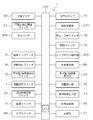
図3は、図1に示す輸液ポンプ1の電気構成例を示すブロック図である。
図3を参照すると、マイクロコンピュータなどのCPUとCPUにより実行される装置全体の制御プログラムや各種データを記憶するROMとワークエリアとして測定データや各種データを一時的に記憶するRAMなどを備え、制御・判断を行なう制御部100には、動作インジケータ6、滴数設定スイッチ8、滴数表示部8A、予定量・積算量設定スイッチ9、注入速度設定スイッチ11、点検時期表示部13、電源スイッチ15、停止・消音スイッチ18、開始スイッチ19、アップ・ダウン操作部200、予定量/積算量表示部23、注入速度表示部32、気泡センサ30S、閉塞圧検出調整スイッチ51、外部通信部56、閉塞センサ62、ドアスイッチ69、音声ICチップ70、記憶部71、点検時期設定スイッチ77、設定変更部270が、電気的に接続されている。
図3を参照すると、マイクロコンピュータなどのCPUとCPUにより実行される装置全体の制御プログラムや各種データを記憶するROMとワークエリアとして測定データや各種データを一時的に記憶するRAMなどを備え、制御・判断を行なう制御部100には、動作インジケータ6、滴数設定スイッチ8、滴数表示部8A、予定量・積算量設定スイッチ9、注入速度設定スイッチ11、点検時期表示部13、電源スイッチ15、停止・消音スイッチ18、開始スイッチ19、アップ・ダウン操作部200、予定量/積算量表示部23、注入速度表示部32、気泡センサ30S、閉塞圧検出調整スイッチ51、外部通信部56、閉塞センサ62、ドアスイッチ69、音声ICチップ70、記憶部71、点検時期設定スイッチ77、設定変更部270が、電気的に接続されている。
図4は、制御部100とアップ・ダウン操作部200等を示すブロック図である。
図4において、アップ・ダウン操作部200の注入速度アップスイッチ201と注入速度ダウンスイッチ202は、制御部100に対して電気的に接続されている。また、メモリ230と、メモリ250と、設定変更部270が、制御部100に対して電気的に接続されている。
医療従事者が、指で図2と図4に示すアップ・ダウン操作部200の注入速度アップスイッチ201を押すことにより、図2に示す輸液チューブ2に通す薬剤の注入速度を上げることができ、医療従事者が、指で図2と図4に示すアップ・ダウン操作部200の注入速度ダウンスイッチ202を押すことにより、図2に示す輸液チューブ2に通す薬剤の注入速度を下げることができる。
図4において、アップ・ダウン操作部200の注入速度アップスイッチ201と注入速度ダウンスイッチ202は、制御部100に対して電気的に接続されている。また、メモリ230と、メモリ250と、設定変更部270が、制御部100に対して電気的に接続されている。
医療従事者が、指で図2と図4に示すアップ・ダウン操作部200の注入速度アップスイッチ201を押すことにより、図2に示す輸液チューブ2に通す薬剤の注入速度を上げることができ、医療従事者が、指で図2と図4に示すアップ・ダウン操作部200の注入速度ダウンスイッチ202を押すことにより、図2に示す輸液チューブ2に通す薬剤の注入速度を下げることができる。
図5は、輸液ポンプ1が輸液チューブ2に通す薬剤の注入速度が、時間経過に伴って変化する注入速度の数値変化例を示している。
図5に示す薬剤の注入速度変化例では、例えば複数回の通常注入速度設定範囲M1、M2、M3と複数回の目標注入速度設定範囲R1、R2、R3が予め設定されている。通常注入速度設定範囲M1、M2、M3と目標注入速度設定範囲R1、R2、R3は交互に設定されている。これらの目標注入速度設定範囲R1、R2、R3とは、輸液ポンプ1により薬剤を輸液する際に、薬剤の注入速度を設定しようとする頻度の高い目標設定値の範囲である。
図5に示す薬剤の注入速度変化例では、例えば複数回の通常注入速度設定範囲M1、M2、M3と複数回の目標注入速度設定範囲R1、R2、R3が予め設定されている。通常注入速度設定範囲M1、M2、M3と目標注入速度設定範囲R1、R2、R3は交互に設定されている。これらの目標注入速度設定範囲R1、R2、R3とは、輸液ポンプ1により薬剤を輸液する際に、薬剤の注入速度を設定しようとする頻度の高い目標設定値の範囲である。
医療従事者が、指で図2と図4に示すアップ・ダウン操作部200の注入速度アップスイッチ201を押し続けることにより、図5に示す目標注入速度設定範囲R1、R2、R3を除く通常注入速度設定範囲M1、M2、M3では、図2に示す輸液チューブ2に通す薬剤の注入速度を一定の第1の傾きLCで直線的に増加することができる。
しかし、医療従事者が、指で図2と図4に示す注入速度アップスイッチ201を押し続けることにより、図5に示す目標注入速度設定範囲R1、R2、R3では、図2に示す輸液チューブ2に通す薬剤の注入速度を一定の第1の傾きLCとは異なる予め定めた第2の傾きTTで直線的に増加することができる。
この目標注入速度設定範囲R1、R2、R3における薬剤の注入速度の予め定めた第2の傾きTTは、通常注入速度設定範囲M1、M2、M3における薬剤の注入速度の一定の第1の傾きLCに比べて小さく設定されている(第2の傾きTT<第1の傾きLC)。
図4に示すメモリ230には、図4に示す制御部100が、図5に例示する目標注入速度設定範囲R1、R2、R3と通常注入速度設定範囲M1、M2、M3に従って、薬剤の注入速度の設定処理を行うことができるようにするためのプログラムが格納されている。
図4に示すメモリ250には、実際に図5に例示するような目標注入速度設定範囲R1、R2、R3と通常注入速度設定範囲M1、M2、M3や、第1の傾きLCと第2の傾きTTの数値例を記憶することができる。
しかし、医療従事者が、指で図2と図4に示す注入速度アップスイッチ201を押し続けることにより、図5に示す目標注入速度設定範囲R1、R2、R3では、図2に示す輸液チューブ2に通す薬剤の注入速度を一定の第1の傾きLCとは異なる予め定めた第2の傾きTTで直線的に増加することができる。
この目標注入速度設定範囲R1、R2、R3における薬剤の注入速度の予め定めた第2の傾きTTは、通常注入速度設定範囲M1、M2、M3における薬剤の注入速度の一定の第1の傾きLCに比べて小さく設定されている(第2の傾きTT<第1の傾きLC)。
図4に示すメモリ230には、図4に示す制御部100が、図5に例示する目標注入速度設定範囲R1、R2、R3と通常注入速度設定範囲M1、M2、M3に従って、薬剤の注入速度の設定処理を行うことができるようにするためのプログラムが格納されている。
図4に示すメモリ250には、実際に図5に例示するような目標注入速度設定範囲R1、R2、R3と通常注入速度設定範囲M1、M2、M3や、第1の傾きLCと第2の傾きTTの数値例を記憶することができる。
一般に、医療従事者が薬剤の注入速度の目標設定値までに設定入力キーを長い時間押し続けると、数値が高速で変化するために、医療従事者が指を設定入力キーから離しても必ずしも目標設定値付近で止まるとは限らず、多くの場合には、注入速度の数値がかなり目標設定値の手前であったり、過ぎたりしてしまう。このため、医療従事者が薬剤の注入速度が注入速度の目標設定値に到達するまでに設定入力キーのアップキーとダウンキーを繰り返して押さないと、注入速度の数値を目標設定値にすることができず、数値設定作業は時間がかかり面倒である。
そこで、本発明の実施形態の輸液ポンプ1を使用すると、医療従事者はより少ない操作回数で、入力する薬剤の注入速度の数値を目標設定値に設定することができる。この輸液ポンプ1の動作例を、図1と図2と図4と図5、そして図6を参照して、以下に説明する。
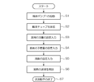
図6は、輸液ポンプ1の動作例を示すフロー図である。
図6のステップS1では、医療従事者は、図2と図3に示す輸液ポンプ1の電源スイッチ15を押して、輸液ポンプ1を起動する。
図6のステップS2では、図2に示すように、医療従事者がドア4を開けて輸液チューブ2を上下位置の溝部3m、3m内にはめ込むとともに輸液チューブ2をチューブガイド94,95にはめ込むことで、輸液チューブ4は上下方向に沿って確実に装着できる。そして、医療従事者はドア4を閉めることで、図1に示すドア4の押圧部材170が輸液チューブ2をポンプ機構部190に押し付ける。このポンプ機構部190の10個のフィンガ10-nが、上から下に向けて順次輸液チューブ2を押すことにより、蠕動式で輸液チューブ2内の薬剤を上から下に向けてZ方向に送液することが可能な状態になる。
図6は、輸液ポンプ1の動作例を示すフロー図である。
図6のステップS1では、医療従事者は、図2と図3に示す輸液ポンプ1の電源スイッチ15を押して、輸液ポンプ1を起動する。
図6のステップS2では、図2に示すように、医療従事者がドア4を開けて輸液チューブ2を上下位置の溝部3m、3m内にはめ込むとともに輸液チューブ2をチューブガイド94,95にはめ込むことで、輸液チューブ4は上下方向に沿って確実に装着できる。そして、医療従事者はドア4を閉めることで、図1に示すドア4の押圧部材170が輸液チューブ2をポンプ機構部190に押し付ける。このポンプ機構部190の10個のフィンガ10-nが、上から下に向けて順次輸液チューブ2を押すことにより、蠕動式で輸液チューブ2内の薬剤を上から下に向けてZ方向に送液することが可能な状態になる。
図6に示すステップS3では、医療従事者は薬剤の注入速度の設定を行う。この場合には、医療従事者が薬剤の注入速度(mL/h)設定を行うために、図2に示す注入速度設定スイッチ11を押して、注入速度表示部32が点滅状態であることを確認後、アップ・ダウン操作部200の注入速度アップスイッチ201を押すことで薬剤の注入速度の数値を入力し、所定の数値であることを確認し、再度、注入速度設定スイッチ11を押すことで薬剤の注入速度の数値を確定入力できる。
このように、アップ・ダウン操作部200の注入速度アップスイッチ201を押して、薬剤の注入速度の数値を入力する場合には、図4に示す制御部100は、メモリ250に記憶されている実際に図5に例示するような目標注入速度設定範囲R1、R2、R3と通常注入速度設定範囲M1、M2、M3や、第1の傾きLCと第2の傾きTTの数値例を読み出して、制御部100は、図5に示すこの注入速度変化例に従って、例えば注入速度(輸液注入速度)(mL/h)の設定入力を1.0~999mL/hの範囲で、次にようにして薬剤の注入速度の設定を行うことができる。
このように、アップ・ダウン操作部200の注入速度アップスイッチ201を押して、薬剤の注入速度の数値を入力する場合には、図4に示す制御部100は、メモリ250に記憶されている実際に図5に例示するような目標注入速度設定範囲R1、R2、R3と通常注入速度設定範囲M1、M2、M3や、第1の傾きLCと第2の傾きTTの数値例を読み出して、制御部100は、図5に示すこの注入速度変化例に従って、例えば注入速度(輸液注入速度)(mL/h)の設定入力を1.0~999mL/hの範囲で、次にようにして薬剤の注入速度の設定を行うことができる。
図2と図5を参照すると、医療従事者が注入速度(mL/h)設定を行う際には、まずこの注入速度設定スイッチ11を押して、注入速度表示部32が点滅状態であることを確認後、アップ・ダウン操作部200の注入速度アップスイッチ201を押して、図5に示す通常注入速度設定範囲M1においては、薬剤の注入速度は、例えば1.0mL/hから注入速度LM1まで、第1の傾きLCで変化して注入速度の増加の速度が高速になるように上昇される。
図5において、薬剤の注入速度が注入速度LM1に達して目標注入速度設定範囲R1の範囲に入ると、薬剤の注入速度は目標注入速度設定範囲R1の範囲では、注入速度LM1から注入速度LM2まで第2の傾きTT(第2の傾きTT<第1の傾きLC)で変化して注入速度の増加の速度が遅くなるように上昇される。このように、目標注入速度設定範囲R1での薬剤の注入速度は、通常注入速度設定範囲M1における薬剤の注入速度に比べて、遅く上昇させることができる。
図5において、薬剤の注入速度が注入速度LM1に達して目標注入速度設定範囲R1の範囲に入ると、薬剤の注入速度は目標注入速度設定範囲R1の範囲では、注入速度LM1から注入速度LM2まで第2の傾きTT(第2の傾きTT<第1の傾きLC)で変化して注入速度の増加の速度が遅くなるように上昇される。このように、目標注入速度設定範囲R1での薬剤の注入速度は、通常注入速度設定範囲M1における薬剤の注入速度に比べて、遅く上昇させることができる。
次に、図5に示す次の通常注入速度設定範囲M2においては、薬剤の注入速度が注入速度LM2からさらに注入速度LM3に向けて第1の傾きLCで変化するようにして注入速度の増加の速度が高速になるように上昇される。図5において、薬剤の注入速度が注入速度LM3に達して目標注入速度設定範囲R2の範囲に入ると、薬剤の注入速度は目標注入速度設定範囲R2の範囲では、注入速度LM3から注入速度LM4まで第2の傾きTT(第2の傾きTT<第1の傾きLC)で変化するようにして注入速度の増加の速度が遅くなるように上昇される。このように、目標注入速度設定範囲R2の薬剤の注入速度は、通常注入速度設定範囲M2における薬剤の注入速度に比べて、遅く上昇させることができる。
さらに、図5に示す次の通常注入速度設定範囲M3においては、薬剤の注入速度が注入速度LM4からさらに注入速度LM5に向けて第1の傾きLCで変化するようにして注入速度の増加速度が高速になるように上昇される。図5において、薬剤の注入速度が注入速度LM5に達して目標注入速度設定範囲R3の範囲に入ると、薬剤の注入速度は目標注入速度設定範囲R3の範囲では、注入速度LM5から注入速度LM6まで第2の傾きTT(第2の傾きTT<第1の傾きLC)で変化するようにして注入速度の増加の速度が遅くなるように上昇される。このように、目標注入速度設定範囲R3の薬剤の注入速度は、通常注入速度設定範囲M3における薬剤の注入速度に比べて、遅く上昇させることができる。
そして、最終的には、医療従事者は、薬剤の注入速度を所定の数値に設定できたことを確認し、再度、図2の注入速度設定スイッチ11を押すことで薬剤の注入速度を確定できる。
そして、最終的には、医療従事者は、薬剤の注入速度を所定の数値に設定できたことを確認し、再度、図2の注入速度設定スイッチ11を押すことで薬剤の注入速度を確定できる。
上述したように、医療従事者は、注入速度アップスイッチ201を押して図5に示すような薬剤の注入速度設定を行うことができるので、図5に示す通常注入速度設定範囲M1、M2、M3では、薬剤の注入速度は第1の傾きLCで変化するようにして注入速度の増加の速度が高速になるように上昇できる。そして、設定する頻度の高い目標注入速度設定範囲R1、R2、R3では、注入速度LM1から注入速度LM2まで第2の傾きTT(第2の傾きTT<第1の傾きLC)で変化するようにして注入速度の増加の速度が遅くなるように上昇できる。このため、薬剤の注入速度が一定の速度で高速に増加する従来の場合に比べて、医療従事者は、アップ・ダウン操作部200を操作して薬剤の注入速度を設定する場合に、より少ない操作回数で、薬剤の注入速度の目標設定値を設定して確定することができる。
なお、医療従事者が注入速度アップスイッチ201から指を離して注入速度アップの操作を止めた時には、図3の制御部100は注入速度表示部32において、止まった注入速度の設定値から最も近いキリの良い設定値を表示させることができる。例えば、医療従事者の指が注入速度アップスイッチ201から離れた時の薬剤の注入速度の値が「54.9mL/h」であるとすれば、図3の制御部100は、止まった注入速度の設定値から最も近いキリの良い設定値まで変えて、例えば注入速度表示部32においては、「55mL/h」として、設定値を表示させることができる。
なお、医療従事者が注入速度アップスイッチ201から指を離して注入速度アップの操作を止めた時には、図3の制御部100は注入速度表示部32において、止まった注入速度の設定値から最も近いキリの良い設定値を表示させることができる。例えば、医療従事者の指が注入速度アップスイッチ201から離れた時の薬剤の注入速度の値が「54.9mL/h」であるとすれば、図3の制御部100は、止まった注入速度の設定値から最も近いキリの良い設定値まで変えて、例えば注入速度表示部32においては、「55mL/h」として、設定値を表示させることができる。
次に、図6に示すステップS4では、医療従事者は薬剤の予定量を設定入力する。この場合には、医療従事者は指で図2に示す予定量設定スイッチ9を押して、隣の予定量/積算量の表示部23の数値を点滅させながら、アップ・ダウン操作部200の注入速度アップスイッチ201と注入速度ダウンスイッチ202を押して、例えば予定量(輸液予定量)(mL)の設定入力を1~9999mLの範囲で行うことができる。
次に、図6に示すステップS5では、医療従事者は薬剤の滴数設定入力を行う。医療従事者は、指で輸液セット選択パネル8を押して、点滅する滴数表示部8Aを見ながら薬剤の点滴数を設定する。
そして、図6に示すステップS6では、医療従事者が図2と図3に示す開始スイッチ19を押して、輸液ポンプ1の動作を開始して、輸液チューブ2を通じて患者に対して薬剤を送液する。ステップS7では、薬剤が予定量送液されたら、輸液ポンプ1を用いた送液動作が終了する。
次に、図6に示すステップS5では、医療従事者は薬剤の滴数設定入力を行う。医療従事者は、指で輸液セット選択パネル8を押して、点滅する滴数表示部8Aを見ながら薬剤の点滴数を設定する。
そして、図6に示すステップS6では、医療従事者が図2と図3に示す開始スイッチ19を押して、輸液ポンプ1の動作を開始して、輸液チューブ2を通じて患者に対して薬剤を送液する。ステップS7では、薬剤が予定量送液されたら、輸液ポンプ1を用いた送液動作が終了する。
ところで、図5に示すこれらの目標注入速度設定範囲R1、R2、R3とは、輸液ポンプ1により薬剤を輸液する際に、薬剤の注入速度を設定しようとする頻度の高い目標設定値の範囲である。そこで、目標注入速度設定範囲R1、R2、R3・・・は、医療従事者が前回輸液ポンプ1により薬剤を輸液する際に前回設定した薬剤の注入速度の目標設定値の範囲を、図5に示すメモリ250に記憶しておいて、医療従事者が、次回輸液ポンプ1により薬剤を輸液する際には、メモリ250に記憶しておいた薬剤の注入速度の目標注入速度設定範囲R1、R2、R3を制御部100に読み出して使用することができる。
あるいは、目標注入速度設定範囲R1、R2、R3・・・は、医療従事者が、輸液ポンプ1により薬剤を以前数回輸液した際に以前数回設定した薬剤の注入速度の目標設定値の範囲を平均化して、図5に示すメモリ250に記憶する。医療従事者が、次回輸液ポンプ1により薬剤を輸液する際に、メモリ250からその平均化した目標注入速度設定範囲R1、R2、R3を制御部100に読み出して使用することができる。
あるいは、目標注入速度設定範囲R1、R2、R3・・・は、医療従事者が、輸液ポンプ1により薬剤を以前数回輸液した際に以前数回設定した薬剤の注入速度の目標設定値の範囲を平均化して、図5に示すメモリ250に記憶する。医療従事者が、次回輸液ポンプ1により薬剤を輸液する際に、メモリ250からその平均化した目標注入速度設定範囲R1、R2、R3を制御部100に読み出して使用することができる。
また、図2と図4に示すように、輸液ポンプ1は、設定変更部270を有している。この設定変更部270は、必要に応じて、図5に示す目標注入速度設定範囲R1、R2、R3・・・の幅、目標注入速度設定範囲R1、R2、R3・・・における第2の傾きTTの値、目標注入速度設定範囲R1、R2、R3・・・の出現回数を変更する際に、医療従事者が指で押すようになっている。
具体的には、例えば、医療従事者が設定変更部270を1回分押した状態では、医療従事者がアップ・ダウン操作部200の注入速度アップスイッチ201あるいは注入速度ダウンスイッチ202を押すことにより、目標注入速度設定範囲R1、R2、R3・・・の幅を増加させたり減少させることができる。
具体的には、例えば、医療従事者が設定変更部270を1回分押した状態では、医療従事者がアップ・ダウン操作部200の注入速度アップスイッチ201あるいは注入速度ダウンスイッチ202を押すことにより、目標注入速度設定範囲R1、R2、R3・・・の幅を増加させたり減少させることができる。
また、医療従事者が設定変更部270を合計2回分押した状態では、医療従事者がアップ・ダウン操作部200の注入速度アップスイッチ201あるいは注入速度ダウンスイッチ202を押すことにより、目標注入速度設定範囲R1、R2、R3・・・における第2の傾きTTの値を大きくしたり小さくすることができる。ただし、第2の第2の傾きTTの変更できる範囲は、第1の傾きLCよりも小さい値の範囲である。
さらに、医療従事者が設定変更部270を合計3回分押した状態では、医療従事者がアップ・ダウン操作部200の注入速度アップスイッチ201あるいは注入速度ダウンスイッチ202を押すことにより、目標注入速度設定範囲R1、R2、R3・・・の設定回数を増加させたり減少させることができる。この場合に、図5の例では、目標注入速度設定範囲R1、R2、R3が設定されているが、2つの目標注入速度設定範囲R1、R2あるいは4つ以上の目標注入速度設定範囲R1、R2、R3、R4を設定することが可能である。
さらに、医療従事者が設定変更部270を合計3回分押した状態では、医療従事者がアップ・ダウン操作部200の注入速度アップスイッチ201あるいは注入速度ダウンスイッチ202を押すことにより、目標注入速度設定範囲R1、R2、R3・・・の設定回数を増加させたり減少させることができる。この場合に、図5の例では、目標注入速度設定範囲R1、R2、R3が設定されているが、2つの目標注入速度設定範囲R1、R2あるいは4つ以上の目標注入速度設定範囲R1、R2、R3、R4を設定することが可能である。
本発明の実施形態の輸液ポンプ1では、医療従事者がより少ない操作回数で入力する数値を目標設定値に設定することができる。すなわち、医療従事者が、薬剤の注入速度入力部を押して薬剤の注入速度を入力する際に通常注入速度設定範囲では薬剤の注入速度を第1の傾きで早い速度で増加させ、薬剤の注入速度が目標注入速度設定範囲に達すると、目標注入速度設定範囲では通常注入速度設定範囲に比べて薬剤の注入速度を第2の傾きで遅い速度で増加させることできるので、医療従事者がより少ない操作回数で入力する注入速度の数値を、注入速度の目標設定値に設定することができる。
ところで、本発明は上記実施形態に限定されず、本発明は様々な修正と変更が可能であり、特許請求の範囲に記載された範囲で種々の変形が可能である。
通常注入速度設定範囲M1、M2、M3と目標注入速度設定範囲R1、R2、R3の設定数は、3つに限らず、2つあるいは4つ以上であってもよい。
また、注入予定量(mL)についても、複数の所定の目標設定範囲を定めて、上述の注入速度設定範囲と同様な制御で、設定できるようにしてもよい。
また、アップ・ダウン操作部200の注入速度アップスイッチ201あるいは注入速度ダウンスイッチ202に変えて、ジョグダイヤルで行なうようにし、目標注入速度設定範囲の近傍では、ジョグダイヤルを回転させる力が重くなるように制御部で制御するようにしてもよい。
図1と図2に示す輸液ポンプ1では、輸液チューブ2が上下方向に沿って設定されるが、これに限らず輸液チューブ2が水平方向に装着される輸液ポンプであっても良い。本発明の輸液ポンプとしては、シリンジを装着してシリンジ内の薬剤を患者に送液するシリンジポンプも含む。
通常注入速度設定範囲M1、M2、M3と目標注入速度設定範囲R1、R2、R3の設定数は、3つに限らず、2つあるいは4つ以上であってもよい。
また、注入予定量(mL)についても、複数の所定の目標設定範囲を定めて、上述の注入速度設定範囲と同様な制御で、設定できるようにしてもよい。
また、アップ・ダウン操作部200の注入速度アップスイッチ201あるいは注入速度ダウンスイッチ202に変えて、ジョグダイヤルで行なうようにし、目標注入速度設定範囲の近傍では、ジョグダイヤルを回転させる力が重くなるように制御部で制御するようにしてもよい。
図1と図2に示す輸液ポンプ1では、輸液チューブ2が上下方向に沿って設定されるが、これに限らず輸液チューブ2が水平方向に装着される輸液ポンプであっても良い。本発明の輸液ポンプとしては、シリンジを装着してシリンジ内の薬剤を患者に送液するシリンジポンプも含む。
1・・・輸液ポンプ、2・・・輸液チューブ(薬剤管路)、3・・・本体ベース、4・・・ドア、100・・・制御部、190・・・ポンプ機構部、200・・・アップ・ダウン操作部(薬剤の注入速度入力部の一例)、201・・・注入速度アップスイッチ、202・・・注入速度ダウンスイッチ、270・・・設定変更部、LC・・・第1の第2の傾きTT・・・第2の傾き、R1、R2、R3・・・標注入速度設定範囲、M1、M2、M3・・・通常注入速度設定範囲
Claims (4)
- 薬剤を患者に対して送液する輸液ポンプであって、
押すことにより前記薬剤の注入速度を入力する薬剤の注入速度入力部と、
前記薬剤の注入速度入力部を押して前記薬剤の注入速度を入力すると前記薬剤の注入速度を第1の傾きで増加させる通常注入速度設定範囲と、前記薬剤の注入速度を前記第1の傾きよりも小さい第2の傾きで増加させる目標注入速度設定範囲を設定する制御部と
を備えることを特徴とする輸液ポンプ。 - 前記薬剤を通す薬剤管路を挟んだ状態で前記薬剤管路を蠕動させることで前記薬剤管路内の前記薬剤を送液するポンプ機構部を有することを特徴とする請求項1に記載の輸液ポンプ。
- 前記ポンプ機構部を有する本体ベースと、前記本体ベースに対して開閉可能であり、前記薬剤管路を上下方向に配置して挟むドアを有することを特徴とする請求項2に記載の輸液ポンプ
- 前記目標注入速度設定範囲の幅と、前記目標注入速度設定範囲における前記第2の傾きの値と、前記目標注入速度設定範囲の出現回数と、を変更するための設定変更部を有することを特徴とする請求項1ないし請求項3のいずれかに記載の輸液ポンプ。
Applications Claiming Priority (2)
| Application Number | Priority Date | Filing Date | Title |
|---|---|---|---|
| JP2011073460A JP2012205736A (ja) | 2011-03-29 | 2011-03-29 | 輸液ポンプ |
| JP2011-073460 | 2011-03-29 |
Publications (1)
| Publication Number | Publication Date |
|---|---|
| WO2012132350A1 true WO2012132350A1 (ja) | 2012-10-04 |
Family
ID=46930131
Family Applications (1)
| Application Number | Title | Priority Date | Filing Date |
|---|---|---|---|
| PCT/JP2012/001993 Ceased WO2012132350A1 (ja) | 2011-03-29 | 2012-03-22 | 輸液ポンプ |
Country Status (2)
| Country | Link |
|---|---|
| JP (1) | JP2012205736A (ja) |
| WO (1) | WO2012132350A1 (ja) |
Cited By (1)
| Publication number | Priority date | Publication date | Assignee | Title |
|---|---|---|---|---|
| CN114366933A (zh) * | 2022-01-24 | 2022-04-19 | 中南大学湘雅二医院 | 一种基于语音控制的流量调节微量泵方法与系统 |
Families Citing this family (1)
| Publication number | Priority date | Publication date | Assignee | Title |
|---|---|---|---|---|
| JP2023180084A (ja) * | 2022-06-08 | 2023-12-20 | 株式会社トップ | 輸液ポンプ |
Citations (3)
| Publication number | Priority date | Publication date | Assignee | Title |
|---|---|---|---|---|
| JPH0239584U (ja) * | 1988-09-06 | 1990-03-16 | ||
| JPH07236692A (ja) * | 1994-03-01 | 1995-09-12 | Terumo Corp | 輸液ポンプ |
| JPH11113741A (ja) * | 1997-10-20 | 1999-04-27 | Matsushita Electric Ind Co Ltd | 機器の時間設定装置 |
-
2011
- 2011-03-29 JP JP2011073460A patent/JP2012205736A/ja active Pending
-
2012
- 2012-03-22 WO PCT/JP2012/001993 patent/WO2012132350A1/ja not_active Ceased
Patent Citations (3)
| Publication number | Priority date | Publication date | Assignee | Title |
|---|---|---|---|---|
| JPH0239584U (ja) * | 1988-09-06 | 1990-03-16 | ||
| JPH07236692A (ja) * | 1994-03-01 | 1995-09-12 | Terumo Corp | 輸液ポンプ |
| JPH11113741A (ja) * | 1997-10-20 | 1999-04-27 | Matsushita Electric Ind Co Ltd | 機器の時間設定装置 |
Cited By (2)
| Publication number | Priority date | Publication date | Assignee | Title |
|---|---|---|---|---|
| CN114366933A (zh) * | 2022-01-24 | 2022-04-19 | 中南大学湘雅二医院 | 一种基于语音控制的流量调节微量泵方法与系统 |
| CN114366933B (zh) * | 2022-01-24 | 2022-08-02 | 中南大学湘雅二医院 | 一种基于语音控制的流量调节微量泵方法与系统 |
Also Published As
| Publication number | Publication date |
|---|---|
| JP2012205736A (ja) | 2012-10-25 |
Similar Documents
| Publication | Publication Date | Title |
|---|---|---|
| JP4638694B2 (ja) | 輸液装置 | |
| JP6114258B2 (ja) | 輸液ポンプ | |
| US10795973B2 (en) | Medicament training device and system | |
| EP2700424A1 (en) | Infusion pump | |
| JPWO2002066102A1 (ja) | シリンジポンプ及び送液方法 | |
| CN105381518A (zh) | 低成本可移动医疗泵 | |
| JP2005021463A (ja) | シリンジポンプ | |
| JPWO2003024385A1 (ja) | 薬剤容器とこれを用いた薬剤注入装置 | |
| JP6240620B2 (ja) | 点滴プローブと点滴プローブを備える輸液ポンプ | |
| EP3201900B1 (en) | Medicament training device and system | |
| JP4477317B2 (ja) | 輸液ポンプ及びシリンジポンプ | |
| KR20160133774A (ko) | 전자식 휴대용 실린더형 의약품 주입펌프 및 이를 이용한 의약품 주입방법 | |
| JP4507233B2 (ja) | 蠕動式輸液装置 | |
| JP2012205736A (ja) | 輸液ポンプ | |
| JP3140940U (ja) | 経腸輸液ポンプ | |
| JP6050576B2 (ja) | 支持部材への取り付けユニットおよびこの取り付けユニットを備える医用ポンプ | |
| JP4034491B2 (ja) | シリンジポンプ及び閉塞検出時の駆動制御方法 | |
| JP3124022U (ja) | 輸液装置 | |
| CN104968379A (zh) | 输液泵 | |
| EP4473986A1 (en) | Infusion pump | |
| JPH07236692A (ja) | 輸液ポンプ | |
| WO2014030184A1 (ja) | 輸液ポンプ | |
| KR20170084583A (ko) | 유체 컨트롤 장치 | |
| JP3581695B2 (ja) | シリンジポンプ | |
| JP2013074917A (ja) | 輸液チューブの処理ユニットおよびこの処理ユニットを備える医用ポンプ |
Legal Events
| Date | Code | Title | Description |
|---|---|---|---|
| 121 | Ep: the epo has been informed by wipo that ep was designated in this application |
Ref document number: 12763622 Country of ref document: EP Kind code of ref document: A1 |
|
| NENP | Non-entry into the national phase |
Ref country code: DE |
|
| 122 | Ep: pct application non-entry in european phase |
Ref document number: 12763622 Country of ref document: EP Kind code of ref document: A1 |