WO2012132227A1 - 排気浄化装置 - Google Patents
排気浄化装置 Download PDFInfo
- Publication number
- WO2012132227A1 WO2012132227A1 PCT/JP2012/001357 JP2012001357W WO2012132227A1 WO 2012132227 A1 WO2012132227 A1 WO 2012132227A1 JP 2012001357 W JP2012001357 W JP 2012001357W WO 2012132227 A1 WO2012132227 A1 WO 2012132227A1
- Authority
- WO
- WIPO (PCT)
- Prior art keywords
- exhaust
- passage
- filter
- nox
- engine
- Prior art date
- Legal status (The legal status is an assumption and is not a legal conclusion. Google has not performed a legal analysis and makes no representation as to the accuracy of the status listed.)
- Ceased
Links
Images



Classifications
-
- F—MECHANICAL ENGINEERING; LIGHTING; HEATING; WEAPONS; BLASTING
- F01—MACHINES OR ENGINES IN GENERAL; ENGINE PLANTS IN GENERAL; STEAM ENGINES
- F01N—GAS-FLOW SILENCERS OR EXHAUST APPARATUS FOR MACHINES OR ENGINES IN GENERAL; GAS-FLOW SILENCERS OR EXHAUST APPARATUS FOR INTERNAL-COMBUSTION ENGINES
- F01N3/00—Exhaust or silencing apparatus having means for purifying, rendering innocuous, or otherwise treating exhaust
- F01N3/08—Exhaust or silencing apparatus having means for purifying, rendering innocuous, or otherwise treating exhaust for rendering innocuous
- F01N3/0807—Exhaust or silencing apparatus having means for purifying, rendering innocuous, or otherwise treating exhaust for rendering innocuous by using absorbents or adsorbents
- F01N3/0871—Exhaust or silencing apparatus having means for purifying, rendering innocuous, or otherwise treating exhaust for rendering innocuous by using absorbents or adsorbents using means for controlling, e.g. purging, the absorbents or adsorbents
- F01N3/0878—Bypassing absorbents or adsorbents
-
- B—PERFORMING OPERATIONS; TRANSPORTING
- B01—PHYSICAL OR CHEMICAL PROCESSES OR APPARATUS IN GENERAL
- B01D—SEPARATION
- B01D53/00—Separation of gases or vapours; Recovering vapours of volatile solvents from gases; Chemical or biological purification of waste gases, e.g. engine exhaust gases, smoke, fumes, flue gases, aerosols
- B01D53/30—Controlling by gas-analysis apparatus
-
- B—PERFORMING OPERATIONS; TRANSPORTING
- B01—PHYSICAL OR CHEMICAL PROCESSES OR APPARATUS IN GENERAL
- B01D—SEPARATION
- B01D53/00—Separation of gases or vapours; Recovering vapours of volatile solvents from gases; Chemical or biological purification of waste gases, e.g. engine exhaust gases, smoke, fumes, flue gases, aerosols
- B01D53/34—Chemical or biological purification of waste gases
- B01D53/92—Chemical or biological purification of waste gases of engine exhaust gases
- B01D53/94—Chemical or biological purification of waste gases of engine exhaust gases by catalytic processes
- B01D53/9459—Removing one or more of nitrogen oxides, carbon monoxide, or hydrocarbons by multiple successive catalytic functions; systems with more than one different function, e.g. zone coated catalysts
- B01D53/9477—Removing one or more of nitrogen oxides, carbon monoxide, or hydrocarbons by multiple successive catalytic functions; systems with more than one different function, e.g. zone coated catalysts with catalysts positioned on separate bricks, e.g. exhaust systems
-
- B—PERFORMING OPERATIONS; TRANSPORTING
- B01—PHYSICAL OR CHEMICAL PROCESSES OR APPARATUS IN GENERAL
- B01D—SEPARATION
- B01D53/00—Separation of gases or vapours; Recovering vapours of volatile solvents from gases; Chemical or biological purification of waste gases, e.g. engine exhaust gases, smoke, fumes, flue gases, aerosols
- B01D53/34—Chemical or biological purification of waste gases
- B01D53/92—Chemical or biological purification of waste gases of engine exhaust gases
- B01D53/94—Chemical or biological purification of waste gases of engine exhaust gases by catalytic processes
- B01D53/9495—Controlling the catalytic process
-
- F—MECHANICAL ENGINEERING; LIGHTING; HEATING; WEAPONS; BLASTING
- F01—MACHINES OR ENGINES IN GENERAL; ENGINE PLANTS IN GENERAL; STEAM ENGINES
- F01N—GAS-FLOW SILENCERS OR EXHAUST APPARATUS FOR MACHINES OR ENGINES IN GENERAL; GAS-FLOW SILENCERS OR EXHAUST APPARATUS FOR INTERNAL-COMBUSTION ENGINES
- F01N13/00—Exhaust or silencing apparatus characterised by constructional features
- F01N13/009—Exhaust or silencing apparatus characterised by constructional features having two or more separate purifying devices arranged in series
- F01N13/0097—Exhaust or silencing apparatus characterised by constructional features having two or more separate purifying devices arranged in series the purifying devices are arranged in a single housing
-
- F—MECHANICAL ENGINEERING; LIGHTING; HEATING; WEAPONS; BLASTING
- F01—MACHINES OR ENGINES IN GENERAL; ENGINE PLANTS IN GENERAL; STEAM ENGINES
- F01N—GAS-FLOW SILENCERS OR EXHAUST APPARATUS FOR MACHINES OR ENGINES IN GENERAL; GAS-FLOW SILENCERS OR EXHAUST APPARATUS FOR INTERNAL-COMBUSTION ENGINES
- F01N3/00—Exhaust or silencing apparatus having means for purifying, rendering innocuous, or otherwise treating exhaust
- F01N3/02—Exhaust or silencing apparatus having means for purifying, rendering innocuous, or otherwise treating exhaust for cooling, or for removing solid constituents of, exhaust
- F01N3/021—Exhaust or silencing apparatus having means for purifying, rendering innocuous, or otherwise treating exhaust for cooling, or for removing solid constituents of, exhaust by means of filters
- F01N3/023—Exhaust or silencing apparatus having means for purifying, rendering innocuous, or otherwise treating exhaust for cooling, or for removing solid constituents of, exhaust by means of filters using means for regenerating the filters, e.g. by burning trapped particles
- F01N3/0231—Exhaust or silencing apparatus having means for purifying, rendering innocuous, or otherwise treating exhaust for cooling, or for removing solid constituents of, exhaust by means of filters using means for regenerating the filters, e.g. by burning trapped particles using special exhaust apparatus upstream of the filter for producing nitrogen dioxide, e.g. for continuous filter regeneration systems [CRT]
-
- F—MECHANICAL ENGINEERING; LIGHTING; HEATING; WEAPONS; BLASTING
- F01—MACHINES OR ENGINES IN GENERAL; ENGINE PLANTS IN GENERAL; STEAM ENGINES
- F01N—GAS-FLOW SILENCERS OR EXHAUST APPARATUS FOR MACHINES OR ENGINES IN GENERAL; GAS-FLOW SILENCERS OR EXHAUST APPARATUS FOR INTERNAL-COMBUSTION ENGINES
- F01N3/00—Exhaust or silencing apparatus having means for purifying, rendering innocuous, or otherwise treating exhaust
- F01N3/02—Exhaust or silencing apparatus having means for purifying, rendering innocuous, or otherwise treating exhaust for cooling, or for removing solid constituents of, exhaust
- F01N3/021—Exhaust or silencing apparatus having means for purifying, rendering innocuous, or otherwise treating exhaust for cooling, or for removing solid constituents of, exhaust by means of filters
- F01N3/033—Exhaust or silencing apparatus having means for purifying, rendering innocuous, or otherwise treating exhaust for cooling, or for removing solid constituents of, exhaust by means of filters in combination with other devices
- F01N3/035—Exhaust or silencing apparatus having means for purifying, rendering innocuous, or otherwise treating exhaust for cooling, or for removing solid constituents of, exhaust by means of filters in combination with other devices with catalytic reactors
-
- B—PERFORMING OPERATIONS; TRANSPORTING
- B01—PHYSICAL OR CHEMICAL PROCESSES OR APPARATUS IN GENERAL
- B01D—SEPARATION
- B01D2251/00—Reactants
- B01D2251/20—Reductants
- B01D2251/208—Hydrocarbons
-
- B—PERFORMING OPERATIONS; TRANSPORTING
- B01—PHYSICAL OR CHEMICAL PROCESSES OR APPARATUS IN GENERAL
- B01D—SEPARATION
- B01D2258/00—Sources of waste gases
- B01D2258/01—Engine exhaust gases
- B01D2258/012—Diesel engines and lean burn gasoline engines
-
- F—MECHANICAL ENGINEERING; LIGHTING; HEATING; WEAPONS; BLASTING
- F02—COMBUSTION ENGINES; HOT-GAS OR COMBUSTION-PRODUCT ENGINE PLANTS
- F02D—CONTROLLING COMBUSTION ENGINES
- F02D41/00—Electrical control of supply of combustible mixture or its constituents
- F02D41/02—Circuit arrangements for generating control signals
- F02D41/021—Introducing corrections for particular conditions exterior to the engine
- F02D41/0235—Introducing corrections for particular conditions exterior to the engine in relation with the state of the exhaust gas treating apparatus
- F02D41/027—Introducing corrections for particular conditions exterior to the engine in relation with the state of the exhaust gas treating apparatus to purge or regenerate the exhaust gas treating apparatus
- F02D41/029—Introducing corrections for particular conditions exterior to the engine in relation with the state of the exhaust gas treating apparatus to purge or regenerate the exhaust gas treating apparatus the exhaust gas treating apparatus being a particulate filter
Definitions
- an exhaust purification device disposed in an exhaust passage of an engine, an NOx (nitrogen oxide) catalyst part, an oxidation catalyst part, and a filter are sequentially arranged from the exhaust upstream side to the exhaust downstream side.
- This exhaust purification device is a fuel (HC (hydrocarbon) component) in exhaust gas from a fuel addition device provided upstream of a NOx catalyst section (HC-SCR catalyst (selective reduction catalyst using hydrocarbon as a reducing agent)). Is added to react the added fuel with NOx to remove NOx in the exhaust and purify the exhaust.
- HC hydrocarbon
- the HC component in the exhaust gas flowing into the oxidation catalyst unit is increased by performing post injection during filter regeneration. Even if the exhaust gas passes through the NOx catalyst part, the NOx in the exhaust gas reacts with the HC component, so that the HC component flowing into the oxidation catalyst part is reduced by the amount of the reaction, and the oxidation of the HC component is performed. In some cases, the filter temperature rise effect (exhaust temperature rise effect) utilizing the reaction cannot be sufficiently obtained. For this reason, exhaust particulates accumulated on the filter cannot be sufficiently removed by combustion, and there is a problem that the pressure loss of the exhaust gas passing through the filter increases or the effect of collecting the exhaust particulates by the filter decreases. .
- the fuel injection amount by post injection is increased in advance by the amount of reaction with NOx.
- the reaction amount between NOx and the HC component is also affected by the temperature of the NOx catalyst portion, it is difficult to accurately predict this reaction amount. Therefore, for example, if the actual reaction amount between NOx and HC components is larger than the predicted value, the amount of HC supplied to the oxidation catalyst section is insufficient, and the regeneration temperature of the filter (exhaust temperature supplied to the filter) is the target. There is a problem that the temperature falls below. Conversely, if the actual reaction amount between NOx and HC components is less than the predicted value, more HC components are supplied to the oxidation catalyst unit than necessary, leading to a deterioration in fuel consumption. There is.
- an object of the present invention is to improve the configuration of an engine exhaust purification device in which a NOx catalyst unit, an oxidation catalyst unit, and a filter are arranged in this order from the exhaust upstream side to the downstream side.
- a NOx catalyst unit a NOx catalyst unit
- an oxidation catalyst unit a filter
- it is possible to prevent the deterioration of the fuel consumption and to reliably perform the regeneration of the filter.
- the exhaust passage of the engine is arranged on the upstream side of the NOx catalyst portion, the first passage for leading the exhaust to the NOx catalyst portion, and the exhaust catalyst without the NOx catalyst portion.
- a control valve is provided in the exhaust passage, and the flow rate of the exhaust gas flowing into the first passage and the flow rate of the exhaust gas flowing into the second passage are controlled by the control valve. The flow rate ratio can be changed.
- the exhaust emission control device of the present invention is disposed in the exhaust passage forming member that forms an exhaust passage through which exhaust from the engine passes, and reduces NOx in the exhaust using HC as a reducing agent.
- NOx catalyst part, oxidation catalyst part disposed downstream of the NOx catalyst part in the exhaust passage, and downstream of the oxidation catalyst part in the exhaust passage, and exhaust particulates contained in the exhaust.
- a filter to collect and a control valve provided in the exhaust passage are provided.
- a portion of the exhaust passage on the upstream side of the NOx catalyst portion includes a first passage that guides exhaust from the engine to the NOx catalyst portion, and the exhaust from the engine without passing through the NOx catalyst portion. It is branched to a second passage leading to the oxidation catalyst part.
- the control valve changes a flow rate ratio between a flow rate of exhaust flowing into the first passage and a flow rate of exhaust flowing into the second passage.
- the exhaust emission control device of the present invention it is possible to prevent the deterioration of fuel consumption and to reliably regenerate the filter.
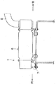
- FIG. 4 is a sectional view taken along line IV-IV in FIG. 3. It is a flowchart which shows an example of normal driving
- FIG. 1 shows a structure in an upper swing body 101 of a hydraulic excavator 100 provided with an exhaust purification device 1 according to an embodiment of the present invention.
- This exhaust purification device 1 (see FIGS. 1 to 3) is applied to exhaust purification processing of a diesel engine 2 (hereinafter simply referred to as an engine) mounted on a hydraulic excavator 100.
- the left side in FIGS. 1 and 2 corresponds to the front of the excavator 100, and the right side corresponds to the rear.
- the engine 2 is an in-line four-cylinder engine, for example, and is disposed in the engine room 3 provided in the upper swing body 101 of the excavator 100.
- a hydraulic pump 4 In the engine room 3, in addition to the engine 2, a hydraulic pump 4, a radiator 5, an exhaust purification device 1, and the like are accommodated.
- Exhaust gas discharged from the engine 2 is guided to the exhaust purification device main body 6 via the exhaust manifold (not shown) and the exhaust pipe 7 and is discharged from the exhaust purification device main body 6 to the atmosphere via the tail pipe 8.
- the exhaust purification device main body 6 has a substantially cylindrical shape, and extends substantially horizontally in a direction orthogonal to the cylinder arrangement direction on the side of the engine 2.
- An exhaust pipe 7 is connected to one end in the longitudinal direction of the exhaust purification apparatus body 6 from below, and a tail pipe 8 is connected to the other end in the longitudinal direction of the exhaust purification apparatus body 6 from above.
- the exhaust pipe 7 and the tail pipe 8 are each connected perpendicularly to the exhaust purification device main body 6.
- the exhaust purification device 1 includes the exhaust purification device main body 6 and the exhaust pipe 7, the NOx catalyst unit 11 that reduces and purifies NOx contained in the exhaust discharged from the engine 2, the HC contained in the exhaust, An oxidation catalyst unit 12 that purifies harmful substances such as CO and a filter 13 that collects exhaust particulates (PM) such as soot contained in the exhaust are provided.
- the assembly combining the exhaust purification device body 6 and the exhaust pipe 7 corresponds to the exhaust passage forming member of the present invention, and forms a series of exhaust passages 10.
- the exhaust passage 10 includes an exhaust passage downstream portion 6 a formed inside the exhaust purification device main body 6 and an exhaust passage upstream portion 7 a formed inside the exhaust pipe 7.
- the NOx catalyst unit 11, the oxidation catalyst unit 12, and the filter 13 are arranged in this order from the upstream side to the downstream side in the exhaust passage downstream portion 6a formed in the exhaust purification device body 6. .
- the NOx catalyst unit 11 is a cylindrical honeycomb having an HC selective reduction type NOx catalyst (hereinafter referred to as HC-SCR catalyst) with enhanced reaction selectivity so that NOx can be selectively reacted with HC even in the presence of oxygen.
- a body (hereinafter referred to as NOx catalyst holder) 14 is held on the cell surface.
- HC-SCR catalyst for example, a well-known base metal oxidation catalyst such as copper-zeolite, iron-zeolite, etc. can be adopted, and the NOx catalyst holding body 14 holding these HC-SCR catalysts can be used.
- alumina or the like can be used.
- the oxidation catalyst portion 12 is a cylindrical honeycomb body (hereinafter referred to as an oxidation catalyst holding body) 15 having a noble metal such as Pt (platinum) coated on the cell surface and coated with a catalyst layer. It is configured to promote an oxidation reaction in which CO and HC are oxidized to produce CO 2 and H 2 O.
- a noble metal such as Pt (platinum) coated on the cell surface and coated with a catalyst layer. It is configured to promote an oxidation reaction in which CO and HC are oxidized to produce CO 2 and H 2 O.
- the filter 13 is a porous ceramic diesel particulate filter (DPF), and its cell surface is coated with a catalyst layer holding a precious metal such as Pt.
- the filter 13 is formed in a cylindrical shape, and the filter 13, the NOx catalyst holding body 14, and the oxidation catalyst holding body 15 are arranged in series and coaxially with each other.
- Each of the holding bodies 14 and 15 and the filter 16 are fixed to the tube wall of the exhaust purification device main body 6.
- the differential pressure detection passage 21 has a differential pressure ⁇ P between the upstream side and the downstream side of the filter.
- a differential pressure detection sensor 22 is provided to detect this.
- a NOx sensor 23 for detecting the NOx concentration in the exhaust gas is provided on the downstream side of the filter 13.
- the NOx sensor 23 corresponds to the NOx concentration detecting means of the present invention.
- the detection signal of the differential pressure detection sensor 22 is output to an ECU (Engine Control Unit) 25 via an electrical connection line E1 (see FIG. 3).
- the detection signal of the NOx sensor 23 is output to the ECU 25 via the electrical connection line E2.
- a portion of the exhaust passage 10 on the upstream side of the NOx catalyst portion 11 (that is, a portion near the downstream end portion of the exhaust passage upstream portion 7a) is a first passage that guides exhaust from the engine 2 to the NOx catalyst portion 11. 27 and a second passage 28 that guides exhaust from the engine 2 to the oxidation catalyst unit 12 without passing through the NOx catalyst unit 11. (See FIG. 3).
- the first passage 27 and the second passage 28 are separated from each other by a partition plate 26 provided at the downstream end of the exhaust pipe 7.
- the partition plate 26 is disposed at the downstream end of the exhaust pipe 7 so as to divide the space of the exhaust passage upstream portion 7a in the exhaust pipe 7 into two in the radial direction (see FIG. 4).
- An end portion on the exhaust gas downstream side of the partition plate 26 is fixed by welding to the outer peripheral surface of the NOx catalyst holding body 14.
- the ratio of the exhaust flow rate flowing into the first passage 27 and the exhaust flow rate flowing into the second passage 28 is set at the portion of the exhaust passage upstream portion 7a that starts to branch into the first passage 27 and the second passage 28.
- a control valve 29 for changing is provided.
- the control valve 29 includes a valve body 31 made of a semicircular plate-like member, and a rotation pin fixed to the valve body 31 so as to rotate integrally with the valve body 31. 32.
- the rotation pin 32 is disposed so as to penetrate the space of the exhaust passage upstream portion 7a in the exhaust pipe 7 in the radial direction. Both ends of the rotation pin 32 are rotatably supported on the tube wall of the exhaust pipe 7, and are rotated integrally with the valve body 31 by the electric motor 33.
- the outer peripheral surface of the rotation pin 32 is in contact with the end surface of the partition plate 26 on the exhaust upstream side so as to be able to rotate and slide.
- the valve body 31 rotates the rotation pin 32 by the electric motor 33, whereby the first passage fully closed position PS ⁇ b> 1 (see FIG. 3) that fully closes the upstream opening of the first passage 27 and the second passage 28. It can be controlled to an arbitrary position between the second passage fully closed position PS2 (normal position described later) for fully closing the upstream side opening.
- the electric motor 33 is controlled by an ECU 25 described later.
- the ECU 25 is composed of a known microcomputer including a CPU, ROM, RAM, and the like.
- the ECU 25 operates the engine 2 and the control valve 29 (electric motor 33) based on detection signals from the NOx sensor 23, the differential pressure detection sensor 22, and various sensors (not shown) attached to the engine 2. Control.
- the ECU 25 includes a determination unit 251, a deposition amount calculation unit 252, a temporary target control position calculation unit 253, a target control position setting unit 254, and a valve control unit 255.
- NOx concentration calculating means 256, HC amount calculating means 257, and HC amount controlling means 258 are provided.
- the determination means 251 is a means for determining whether or not the regeneration of the filter 13 is necessary. In this embodiment, whether or not the differential pressure ⁇ P detected by the differential pressure detection sensor 22 is less than a preset first threshold pressure. Whether or not it is necessary to regenerate the filter 13 is determined depending on whether or not it is necessary.
- the accumulation amount calculation means 252 calculates the amount of exhaust particulate accumulated on the filter 13 based on the differential pressure ⁇ P detected by the differential pressure detection sensor 22.
- the accumulation amount detection means for detecting the amount of exhaust particulate deposited on the filter 13 in the present invention is constituted by the differential pressure detection sensor 22 and the accumulation amount calculation means 252.
- the temporary target control position calculation unit 253 calculates the temporary target control position of the control valve 29 based on the exhaust particulate amount calculated by the accumulation amount calculation unit 252.
- the target control position setting means 254 corrects the temporary target control position based on the NOx concentration calculated by the NOx concentration calculation means 256, and uses the corrected temporary target control position as the true target control position of the control valve 29. Set.
- the valve control means 255 controls the operation of the control valve 29 based on the determination result by the determination means 251 and the target control position set by the target control position control means 254. Specifically, the valve control means 255 controls the motor 33 that drives the control valve 29.
- the NOx concentration calculating means 256 calculates the NOx concentration on the downstream side of the filter 13 based on the detection signal from the NOx sensor 23.
- the HC amount calculating unit 257 calculates the HC amount necessary for the NOx reduction reaction in the NOx catalyst unit 11 based on the NOx concentration calculated by the NOx concentration calculating unit 256.
- the HC amount control means 258 controls an injector (fuel injection valve) that injects fuel in the engine 2 so that the HC amount calculated by the HC amount calculation means 257 is obtained.
- the ECU 25 configured as described above determines that regeneration of the filter 13 is not necessary and performs normal operation. Execute control. Specifically, when the ECU 25 determines that the regeneration of the filter 13 is not necessary, the ECU 25 moves the control valve 29 to the normal position (the position indicated by the two-dot chain line in FIG.
- the HC amount is calculated, and post-injection is performed into the combustion chamber of the engine 2 to supply the calculated HC amount into the exhaust gas. This post-injection is performed in the compression process prior to the main injection near the compression top dead center.
- the ECU 25 determines that regeneration of the filter 13 is necessary and executes filter regeneration control when the differential pressure ⁇ P detected by the differential pressure detection sensor 22 is equal to or higher than the first threshold pressure. Specifically, when the ECU 25 determines that the filter regeneration control is necessary, the ECU 25 calculates the amount of exhaust particulate accumulated on the filter 13 based on the differential pressure ⁇ P detected by the differential pressure detection sensor 22, and calculates the calculation.
- the temporary target control position of the control valve 29 is calculated based on the exhaust particulate amount. This temporary target control position is a position in the range between the first passage fully closed position PS1 and the second passage fully closed position PS2, and the second passage 28 corresponds to the increased amount of exhaust particulates. It is calculated based on map data stored in advance by the ECU 25 so that the exhaust flow rate flowing into the engine increases.
- the ECU 25 corrects the calculated temporary target control position according to the NOx concentration detected by the NOx sensor 23.
- the ECU 25 corrects the temporary target control position so that the exhaust flow rate flowing into the first passage 27 increases in response to the increase in the NOx concentration detected by the NOx sensor 23, and the correction is performed.
- the temporary target control position thus set is set as the true target control position of the control valve 29.
- the ECU 25 calculates the amount of HC necessary for NOx reduction in the NOx catalyst unit 11 and the amount of HC necessary for raising the temperature of the exhaust gas in the oxidation catalyst unit 12, and the calculated HC amount is being exhausted. Post-injection is performed in the combustion chamber of the engine 2 to supply to the engine.
- the ECU 25 reads a concentration signal from the NOx sensor 23, a pressure signal from the differential pressure detection sensor 22, and signals from various sensors attached to the engine 2.
- step S2 the ECU 25 calculates the differential pressure ⁇ P on the upstream side and the downstream side of the filter 13 based on the pressure signal from the differential pressure detection sensor 22 read in step S1, and the differential pressure ⁇ P is a first threshold value. It is determined whether the pressure is equal to or higher than the pressure. If this determination is NO, the process proceeds to step S13. On the other hand, if the determination is yes, the process proceeds to step S3.
- step S3 the ECU 25 executes a filter regeneration program stored in a ROM (not shown) included in the ECU 25 in order to start filter regeneration control.
- step S4 the ECU 25 calculates the accumulation amount (PM accumulation amount) of the exhaust particulate deposited on the filter 13 based on the differential pressure ⁇ P calculated in step S2.
- step S5 the ECU 25 calculates the temporary target control position of the control valve 29 based on the accumulated amount of exhaust particulates calculated in step S4.
- step S6 the ECU 25 calculates the NOx concentration on the downstream side of the filter 13 based on the detection signal from the NOx sensor 23 read in step S1.
- step S7 the ECU 25 determines the target control position of the control valve 29 by correcting the calculated temporary target control position in accordance with the NOx concentration calculated in step S6.
- step S8 the ECU 25 outputs a necessary control signal to the electric motor 33 in order to control the control valve 29 to the target control position.
- step S9 the ECU 25 calculates the NOx concentration in the exhaust on the upstream side of the NOx catalyst unit 11 based on the detection signals from the various sensors of the engine 2, and based on the calculated NOx concentration, the NOx catalyst unit. 11 calculates the amount of HC necessary for the NOx reduction reaction. Further, the ECU 25 calculates the amount of HC required in the oxidation catalyst unit 12 for burning and removing the exhaust particulates based on the accumulation amount of the exhaust particulates calculated in step S4. What is necessary is just to estimate the driving
- step S10 the ECU 25 controls the injector (fuel injection valve) of the engine to execute the main injection, and then in the exhaust immediately after being discharged from the engine 2 (in the exhaust on the upstream side of the NOx catalyst unit 11).
- a necessary control signal is output to the injector (fuel injection valve) so that the HC amount of the fuel becomes equal to the HC amount calculated in step S9, and the injector is controlled to perform post injection.
- step S11 the ECU 25 reads the detection signal from the differential pressure detection sensor 22, calculates the current differential pressure ⁇ P, and the calculated differential pressure is equal to or lower than the second threshold pressure ( ⁇ first threshold pressure). If the determination is NO, the process returns to step S2. On the other hand, if the determination is YES, the process proceeds to step S12. In step S12, the filter regeneration control is terminated, and then the process starts. Return.
- step S13 that proceeds when the determination in step S2 is NO, the ECU 25 controls the electric motor 33 to control the control valve 29 to the normal position (second passage fully closed position PS2) described above. Is output.
- step S14 the ECU 25 calculates (estimates) the NOx concentration in the exhaust discharged from the engine 2 based on detection signals from various sensors of the engine 2, and based on the calculated NOx concentration, the NOx catalyst. The amount of HC required for the reduction reaction of NOx in the part 11 is calculated.
- step S15 the ECU 25 controls the injector of the engine to perform main injection. Thereafter, the ECU 25 controls the injector so that the HC amount in the exhaust immediately after being discharged from the engine 2 becomes the HC amount calculated in step S14. Then, a necessary control signal is output to control the injector to perform post-injection, and then the process returns to the start.
- step S13 the ECU 25 executes the process of step S13 and is controlled by the ECU 25.
- the valve 29 is controlled to the normal position (second passage fully closed position PS2). For this reason, the upstream opening of the second passage 28 is fully closed by the control valve 29, and the inflow of exhaust gas into the second passage 28 is blocked. As a result, all exhaust from the engine 2 is discharged from the first passage 27. After being supplied to the NOx catalyst unit 11, it is discharged into the atmosphere via the oxidation catalyst unit 12 and the filter 13.
- the ECU 25 executes the processing of steps S3 to S8, and the control valve 29 is controlled between the first passage fully closed position PS1 and the second passage fully closed position PS2 by the ECU 25.
- the target control position is controlled.
- the exhaust gas from the engine 2 flows into the oxidation catalyst unit 12 without passing through the NOx catalyst unit 11 from the second channel 28 and the flow F1 (see FIG. 3) flowing into the NOx catalyst unit 11 from the first passage 27. Branches to flow F2 (see FIG. 3).
- the HC component in the exhaust gas flowing into the NOx catalyst unit 11 from the first passage 27 is used for the NOx reduction reaction in the NOx catalyst unit 11.
- the HC component in the exhaust gas flowing into the oxidation catalyst unit 12 from the second passage 28 is used for the oxidation reaction in the oxidation catalyst unit 12, and the temperature of the exhaust gas is raised by the reaction heat generated at this time.
- the heated exhaust gas is supplied to the filter 13 so that the temperature of the filter 13 reaches a target temperature (a temperature at which the exhaust particulates can be combusted), and the exhaust particulates accumulated on the filter are removed by combustion.
- a target temperature a temperature at which the exhaust particulates can be combusted
- the exhaust particulates accumulated on the filter are removed by combustion.
- the HC component necessary in the oxidation catalyst unit 12 at the time of filter regeneration is directly supplied to the oxidation catalyst unit 12 from the second passage 28 without passing through the NOx catalyst unit 11.
- the amount of HC supplied to the oxidation catalyst unit 12 at the time of filter regeneration can be accurately controlled, whereby the regeneration of the filter 13 can be reliably performed while preventing the deterioration of fuel consumption associated with filter
- the ECU 25 executes the process of step S5 (and step S8), and flows into the second passage 28 in response to the increase in the amount of exhaust particulates accumulated on the filter 13.
- the position of the control valve 29 is controlled by the ECU 25 so that the exhaust flow rate to be increased. Accordingly, the HC component supplied to the oxidation catalyst unit 12 via the second passage 28 can be increased in response to the increase in the amount of exhaust particulates accumulated on the filter 13, and as a result, the oxidation catalyst
- the temperature of the exhaust gas supplied to the filter 13 can be increased by promoting the oxidation reaction of the HC component in the section 12. Therefore, the exhaust particulate deposited on the filter 13 can be efficiently and reliably burned and removed according to the amount of deposition.
- the ECU 25 executes the process of step S7, and the position of the control valve 29 is controlled according to the NOx concentration on the downstream side of the filter 13.
- the fall of the NOx purification rate during filter regeneration can be suppressed as much as possible. That is, at the time of filter regeneration, as described above, part of the exhaust from the engine 2 flows directly from the second passage 28 into the oxidation catalyst unit 12 without passing through the NOx catalyst unit 11. For this reason, if the amount of exhaust gas passing through the second passage 28 is too large, the amount of exhaust gas supplied from the first passage 27 to the NOx catalyst unit 11 may decrease and the NOx purification efficiency during filter regeneration may decrease. is there.
- the NOx concentration on the downstream side of the filter 13 detected by the NOx sensor 23 becomes high, so that the NOx catalyst unit 11 is connected from the first passage 27.
- the ECU 25 supplies the HC amount necessary for the NOx reduction reaction and the HC amount necessary for increasing the temperature of the filter 13 (HC amount necessary for the oxidation catalyst unit 12) into the exhaust gas.
- post-injection is performed in the combustion chamber of the engine 2 (the processing of step S10 and step S15 is executed). Therefore, it is not necessary to separately provide an HC addition device or the like in order to secure these necessary HC amounts. Therefore, the number of parts can be reduced, and the exhaust purification device 1 can be made compact and low in cost.
- the dedicated piping required when the fuel addition device is provided is not necessary, troubles such as fuel leakage can be prevented and safety can be improved.
- the exhaust purification device 1 needs to be housed in the narrow engine room 3 together with the accessory equipment such as the hydraulic pump 4, so that compared to passenger cars, trucks, etc.
- the installation space is limited, in the above-described embodiment, as described above, there is no need to separately provide a fuel addition device, so the exhaust purification device 1 can be downsized and efficiently disposed in the narrow engine room 3. .
- the configuration of the present invention is not limited to the above embodiment, but includes various other configurations. That is, in the above embodiment, at the time of filter regeneration, the control valve 29 is controlled to a position in a range between the first passage fully closed position PS1 and the second passage fully closed position PS2, so that the first passage 27 and the second passage
- the present invention is not limited to this.
- the control valve 29 may be controlled to the first passage fully closed position PS1 during filter regeneration. .
- control valve 29 shall have the one valve body 31, it is not restricted to this,
- the control valve 29 is the 1st channel
- the determination as to whether or not the regeneration of the filter 13 is necessary is performed based on the differential pressure detected by the differential pressure detection sensor 22, but the present invention is not limited to this.
- the ECU 25 estimates the amount of exhaust particulates accumulated on the filter 13 based on the history of the operating state (combustion state etc.) of the engine 2, and whether the filter 13 needs to be regenerated based on the estimated amount of exhaust particulates. Such a determination may be made.
- the ECU 25 may execute the timer control to determine that the filter 13 needs to be regenerated every predetermined time and execute the regeneration control of the filter 13.
- the NOx sensor 23 is disposed on the downstream side of the filter 13.
- the NOx sensor 23 may be disposed anywhere on the downstream side of the NOx catalyst unit 11.
- the NOx concentration on the downstream side of the filter 13 is detected by the NOx sensor 23.
- the present invention is not limited to this.
- the ECU 25 is based on detection signals from various sensors. The operating state of the engine 2 may be estimated, and the NOx concentration may be estimated (detected) based on the estimated operating state.
- post injection is performed in the combustion chamber of the engine 2 in order to supply the HC amount necessary for NOx reduction and the HC amount necessary for increasing the temperature of the filter 13 into the exhaust gas.
- after injection may be performed instead of post injection, or after injection may be further performed in addition to post injection.
- a fuel addition device may be separately provided in order to ensure the necessary amount of HC.
- the exhaust purification device 1 is applied to the diesel engine 2.
- the present invention is not limited to this.
- the exhaust purification device 1 may be applied to a gasoline engine.
- the engine 2 is not limited to an in-line four-cylinder engine, and may be a horizontally opposed type or a V-type engine, and the number of cylinders is not limited to four.
- the number of cylinders may be three or less or five or more. Good.
- the HC-SCR catalyst is used as the catalyst for reducing NOx.
- a NOx storage reduction catalyst may be used.
- the engine 2 is preferably a gasoline engine.
- the exhaust purification apparatus of the present invention includes an exhaust passage forming member that forms an exhaust passage through which exhaust from an engine passes, and a NOx catalyst portion that is disposed in the exhaust passage and that reduces NOx in the exhaust using HC as a reducing agent. And an oxidation catalyst portion disposed downstream of the NOx catalyst portion in the exhaust passage and a downstream portion of the oxidation catalyst portion in the exhaust passage and collecting exhaust particulates contained in the exhaust gas.
- a filter and a control valve provided in the exhaust passage, and a portion of the exhaust passage upstream of the NOx catalyst portion includes a first passage for guiding exhaust from the engine to the NOx catalyst portion.
- the exhaust from the engine is branched to a second passage that guides the exhaust to the oxidation catalyst without passing through the NOx catalyst, and the control valve controls the flow rate of the exhaust flowing into the first passage and the second passage. Changing the flow ratio between the flow rate of the exhaust gas flowing, characterized in that.
- part (or all) of exhaust from the engine can be caused to flow into the second passage by controlling the operation (position) of the control valve.
- the exhaust gas flowing into the second passage is directly supplied to the oxidation catalyst unit without passing through the NOx catalyst unit.
- the oxidation catalyst section the oxidation reaction of the HC component in the exhaust gas supplied from the second passage is promoted, and the temperature of the exhaust gas is raised by the reaction heat generated at this time.
- the heated exhaust gas is supplied to the filter, so that the filter temperature rises to the target temperature and the exhaust particulates deposited on the filter are burned and removed.
- the HC component necessary for the temperature rise of the filter (filter regeneration) can be directly supplied from the second passage to the oxidation catalyst unit without passing through the NOx catalyst unit. Therefore, the control valve accurately controls the amount of HC supplied to the oxidation catalyst unit during filter regeneration by changing the flow rate ratio between the flow rate of the exhaust gas flowing into the first passage and the flow rate of the exhaust gas flowing into the second passage. can do. Thereby, the regeneration of the filter can be reliably performed while preventing the deterioration of the fuel consumption.
- a determination unit that determines whether or not the regeneration of the filter is necessary
- a valve control unit that controls the operation of the control valve based on a determination result by the determination unit.
- the valve control unit controls the operation of the control valve on the basis of the determination result by the determination unit that determines whether or not the filter needs to be regenerated, and is supplied to the oxidation catalyst unit at the time of filter regeneration.
- the amount of HC can be accurately controlled. Thereby, the regeneration of the filter can be reliably performed while preventing the deterioration of the fuel consumption.
- valve control means causes the control valve to discharge exhaust from the engine into one of the first and second paths.
- the control valve causes exhaust from the engine to flow into both the first and second passages. It is preferable.
- the control valve blocks the flow of the exhaust gas into the second passage, whereby the exhaust from the engine is all exhausted. It can be discharged into the atmosphere from one passage through the NOx catalyst section. Therefore, when it is not necessary to regenerate the filter, NOx in the exhaust can be sufficiently reduced by the NOx catalyst unit, and the purification efficiency of NOx in the exhaust can be improved.
- the control valve allows the exhaust to flow into both the first and second passages.
- the NOx catalyst can be directly supplied from the second passage without passing through the NOx catalyst, whereby the amount of HC supplied to the oxidation catalyst unit at the time of filter regeneration can be accurately controlled.
- the filter can be reliably regenerated while preventing the deterioration.
- the valve control means is configured to detect the deposit amount detecting means when the judging means determines that regeneration of the filter is necessary. It is preferable to control the operation of the control valve so as to increase the flow rate of the exhaust gas flowing into the second passage in response to the increase in the amount of exhaust particulates detected by the above.
- the flow rate of the exhaust gas flowing into the oxidation catalyst unit from the second passage is increased, and thereby the oxidation catalyst unit together with the exhaust gas.
- the amount of inflowing HC can be increased. Accordingly, in response to an increase in the amount of exhaust particulates deposited on the filter, the oxidation reaction of the HC component in the oxidation catalyst unit is promoted, and the temperature of the exhaust gas supplied to the filter through the oxidation catalyst unit is increased. Can be increased. Therefore, the exhaust particulate deposited on the filter can be efficiently and reliably burned and removed according to the amount of deposition.
- the apparatus further comprises NOx concentration detection means that is disposed downstream of the NOx catalyst section and detects NOx concentration in the exhaust, and the valve control means is based on the NOx concentration detected by the NOx concentration detection means.
- the control valve is preferably configured to be controlled.
- the valve control unit controls the control valve based on the NOx concentration detected by the NOx concentration detection unit, the filter regeneration is performed efficiently and reliably while preventing the NOx purification rate from being lowered. be able to.
- valve control means flows into the first passage in response to an increase in the NOx concentration detected by the NOx concentration detection means when the determination means determines that regeneration of the filter is necessary. It is preferable to control the control valve so as to increase the flow rate of exhaust gas.
- part (or all) of the exhaust from the engine flows directly into the oxidation catalyst portion from the second passage without passing through the NOx catalyst portion. For this reason, if the amount of exhaust gas passing through the second passage is too large, the flow rate of exhaust gas supplied from the first passage to the NOx catalyst unit may decrease, and the NOx purification efficiency during filter regeneration may decrease.
- the flow rate of the exhaust gas flowing into the NOx catalyst unit from the first passage in response to the increase in the NOx concentration of the exhaust gas detected by the NOx concentration detecting means during the regeneration of the filter Therefore, filter regeneration can be performed efficiently and reliably while suppressing a decrease in NOx purification performance during filter regeneration as much as possible.
- HC amount control means for controlling the amount of HC in the exhaust discharged from the engine by post-injecting or after-injecting fuel into the cylinder of the engine.
- the entire device in order to supply the amount of HC necessary for the reduction reaction of NOx in the exhaust and the amount of HC necessary for the temperature rise of the filter (the amount of HC necessary for the oxidation catalyst unit) into the exhaust, Further, since it is not necessary to provide a fuel (HC) addition device or the like, the entire device can be made compact.
- the NOx catalyst part includes a cylindrical NOx catalyst holding body that holds a NOx catalyst
- the oxidation catalyst part includes a cylindrical oxidation catalyst holding body that holds an oxidation catalyst
- the filter is cylindrical.
- the NOx catalyst holder, the oxidation catalyst holder, and the filter are preferably arranged in series and coaxially.
- the cylindrical NOx catalyst holding body that holds the NOx catalyst, the cylindrical oxidation catalyst holding body that holds the oxidation catalyst, and the cylindrical filter are arranged in series and coaxially.
- the entire apparatus can be made compact.
- the present invention is useful for an engine exhaust purification device, and particularly useful for an engine exhaust purification device mounted on a construction machine such as an excavator.
Landscapes
- Engineering & Computer Science (AREA)
- Chemical & Material Sciences (AREA)
- Combustion & Propulsion (AREA)
- Mechanical Engineering (AREA)
- Analytical Chemistry (AREA)
- Chemical Kinetics & Catalysis (AREA)
- General Engineering & Computer Science (AREA)
- General Chemical & Material Sciences (AREA)
- Oil, Petroleum & Natural Gas (AREA)
- Biomedical Technology (AREA)
- Environmental & Geological Engineering (AREA)
- Health & Medical Sciences (AREA)
- Processes For Solid Components From Exhaust (AREA)
- Exhaust Gas After Treatment (AREA)
- Electrical Control Of Air Or Fuel Supplied To Internal-Combustion Engine (AREA)
- Exhaust Gas Treatment By Means Of Catalyst (AREA)
Abstract
NOx触媒部11、酸化触媒部12、及びフィルタ13を排気上流側から下流側に向かってこの順番で配置したエンジンの排気浄化装置において、燃費の悪化を防止し、かつ、フィルタ13の再生を確実に実行することを目的とする。この排気浄化装置では、排気通路10におけるNOx触媒部11の上流側の部分は、排気をNOx触媒部11へと導く第1通路27と排気をNOx触媒部11を介さずに酸化触媒部12へと導く第2通路28とに分岐されている。それとともに、該排気通路中に制御弁29が設けられている。該制御弁29により、該第1通路27に流入する排気の流量と該第2通路28に流入する排気の流量との流量比率を変更することができる。
Description
エンジンの排気浄化装置に関する技術分野に属する。
従来より、エンジンの排気通路に配設される排気浄化装置として、排気上流側から排気下流側に向かって、NOx(窒素酸化物)触媒部、酸化触媒部、及びフィルタを順に配置したものが知られている(例えば、特許文献1の図6参照)。この排気浄化装置は、NOx触媒部(HC-SCR触媒(炭化水素を還元剤とする選択還元触媒))の上流側に設けられた燃料添加装置から排気中に燃料(HC(炭化水素)成分)を添加することで、添加燃料とNOxとを反応させて、排気中のNOxを除去して排気を浄化する。
上記排気浄化装置では、フィルタに排気微粒子(PM:Particulate Matter)が堆積することにより排気微粒子の捕集効率が低下するという問題があり、この問題を解決するべく、現在までに様々なフィルタ再生技術が提案されている。例えば、特許文献2に示すものでは、フィルタ再生時にエンジンの燃焼室にポスト噴射を行うことで、排気中のHC成分を増加させて酸化触媒部におけるHC成分の酸化反応を促進し、このとき生じる反応熱により、フィルタ温度(フィルタに供給される排気温度)を上昇させてフィルタを再生させる。
しかしながら、NOx触媒部の下流側に酸化触媒部を配設するようにした上述の排気浄化装置では、フィルタ再生時に、ポスト噴射を実行することで酸化触媒部に流入する排気中のHC成分を増加させようとしても、排気がNOx触媒部を通過する際に排気中のNOxとHC成分とが反応するため、その反応分だけ酸化触媒部に流入するHC成分が減少して、該HC成分の酸化反応を利用したフィルタ昇温効果(排気昇温効果)を十分に得られない場合がある。このため、フィルタに堆積した排気微粒子を十分に燃焼除去することができず、フィルタを通過する排気の圧力損失が増加したり、フィルタによる排気微粒子の捕集効果が低下したりするという問題がある。
これに対して、ポスト噴射による燃料噴射量を予め、NOxとの反応分だけ増量しておくことが考えられる。しかし、NOxとHC成分との反応量はNOx触媒部の温度等にも影響されるため、この反応量を正確に予測することは困難である。したがって、例えば、NOxとHC成分との実際の反応量が予測値よりも多いと、酸化触媒部に供給されるHC量が不足してフィルタの再生温度(フィルタに供給される排気温度)が目標温度を下回ってしまうという問題がある。逆に、NOxとHC成分との実際の反応量が予測値よりも少ないと、酸化触媒部に対して必要以上に多くのHC成分が供給されることとなって、燃費の悪化を招くという問題がある。
このような点に鑑みて、本発明の目的は、NOx触媒部、酸化触媒部、及びフィルタを排気上流側から下流側に向かってこの順で配置したエンジンの排気浄化装置の構成を改良することにより、燃費の悪化を防止し、かつ、フィルタの再生を確実に実行することである。
上記の目的を達成するために、本発明では、エンジンの排気通路を、NOx触媒部の上流側において、排気をNOx触媒部へと導く第1通路と排気をNOx触媒部を介さずに酸化触媒部へと導く第2通路とに分岐させるとともに、該排気通路中に制御弁を設けて、該制御弁により、該第1通路に流入する排気の流量と該第2通路に流入する排気の流量との流量比率を変更可能にした。
具体的には、本発明の排気浄化装置は、エンジンからの排気が通る排気通路を形成する排気通路形成部材と、上記排気通路に配設され、HCを還元剤として排気中のNOxを還元するNOx触媒部と、上記排気通路における上記NOx触媒部の下流側に配設された酸化触媒部と、上記排気通路における上記酸化触媒部の下流側に配設され、排気中に含まれる排気微粒子を捕集するフィルタと、上記排気通路に設けられた制御弁とを備えている。
そして、上記排気通路における上記NOx触媒部の上流側の部分は、上記エンジンからの排気を上記NOx触媒部へと導く第1通路と、上記エンジンからの排気を上記NOx触媒部を介さずに上記酸化触媒部へと導く第2通路とに分岐されている。上記制御弁は、上記第1通路に流入する排気の流量と上記第2通路に流入する排気の流量との流量比率を変更する。
本発明の排気浄化装置によれば、燃費の悪化を防止し、かつ、フィルタの再生を確実に行うことができる。
以下、本発明の実施形態を図面に基づいて詳細に説明する。
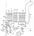
図1は、本発明の実施形態に係る排気浄化装置1を備えた油圧ショベル100の上部旋回体101内の構造を示している。この排気浄化装置1(図1~図3参照)は、油圧ショベル100に搭載されたディーゼルエンジン2(以下、単にエンジンという)の排気浄化処理に適用される。なお、本実施形態では、図1~2における左側が油圧ショベル100の前方に対応し、右側が後方を対応している。
上記エンジン2は、例えば直列4気筒エンジンであって、油圧ショベル100の上部旋回体101に設けられたエンジンルーム3内に配設されている。エンジンルーム3内には、エンジン2の他にも、油圧ポンプ4や、ラジエータ5、排気浄化装置1等が収容されている。エンジン2から排出される排気は、排気マニホールド(図示省略)及び排気パイプ7を介して排気浄化装置本体6に導かれ、排気浄化装置本体6からテールパイプ8を介して大気中に排出される。
排気浄化装置本体6は、略円筒状をなしていて、エンジン2の側方において気筒配列方向に直交する方向に略水平に延びている。排気浄化装置本体6の長手方向の一端部には排気パイプ7が下方から接続され、排気浄化装置本体6の長手方向の他端部にはテールパイプ8が上側から接続されている。排気パイプ7及びテールパイプ8はそれぞれ排気浄化装置本体6に対して垂直に接続されている。
上記排気浄化装置1は、上記の排気浄化装置本体6および排気パイプ7と、エンジン2から排出される排気に含まれるNOxを還元して浄化するNOx触媒部11と、排気中に含まれるHC、CO等の有害物質を浄化する酸化触媒部12と、排気中に含まれる煤等の排気微粒子(PM)を捕集するフィルタ13とを備えている。
排気浄化装置本体6および排気パイプ7を組み合わせた集合体は、本発明の排気通路形成部材に対応しており、一連の排気通路10を形成している。排気通路10は、排気浄化装置本体6の内部に形成された排気通路下流側部分6aと、排気パイプ7の内部に形成された排気通路上流側部分7aとから構成されている。
NOx触媒部11、酸化触媒部12、及びフィルタ13は、上記排気浄化装置本体6内に形成された排気通路下流側部分6aに、上流側から下流側に向かってこの順番で配設されている。
上記NOx触媒部11は、酸素共存下でも選択的にNOxをHCと反応させ得るよう反応選択性を高めたHC選択還元型NOx触媒(以下、HC-SCR触媒と言う)を、円筒状のハニカム体(以下、NOx触媒保持体という)14のセル表面に保持して構成されている。このHC-SCR触媒には、例えば、銅―ゼオライト,鉄―ゼオライト等の周知の卑金属系酸化触媒を採用することができ、また、これらHC-SCR触媒を保持しているNOx触媒保持体14には、例えばアルミナ等を採用することができる。
上記酸化触媒部12は、円筒状のハニカム体(以下、酸化触媒保持体という)15のセル表面にPt(白金)などの貴金属を保持して触媒層をコートしたものであって、排気中のCO、HCを酸化してCO2及びH2Oを生成する酸化反応を促進するように構成されている。
上記フィルタ13は、多孔質のセラミックス製のディーゼル・パティキュレート・フィルタ(DPF)であって、そのセル表面にはPtなどの貴金属を保持した触媒層をコートさせている。フィルタ13は円筒状に形成されており、該フィルタ13、上記NOx触媒保持体14、及び上記酸化触媒保持体15とは、互いに直列に且つ同軸に配設されている。各保持体14,15、及びフィルタ16はそれぞれ、排気浄化装置本体6の管壁に固定されている。
上記排気通路下流側部分6aにおけるフィルタ13の上流側及び下流側は差圧検出通路21を介して連通しており、この差圧検出通路21には、フィルタ上流側及び下流側間の差圧ΔPを検出するべく差圧検出センサ22が設けられている。また、上記フィルタ13の下流側には、排気中のNOx濃度を検出するためのNOxセンサ23が設けられている。NOxセンサ23は、本発明のNOx濃度検出手段に対応する。
差圧検出センサ22の検出信号は、電気接続ラインE1(図3参照)を介してECU(Engine Control Unit)25へと出力される。同様に、NOxセンサ23の検出信号は、電気接続ラインE2を介してECU25へと出力される。
上記排気通路10のNOx触媒部11の上流側の部分(すなわち、排気通路上流側部分7aの下流側端部付近の部分)は、エンジン2からの排気をNOx触媒部11へと導く第1通路27と、エンジン2からの排気をNOx触媒部11を介さずに酸化触媒部12へと導く第2通路28とに分岐されている。(図3参照)。
第1通路27と第2通路28とは、排気パイプ7の下流側端部に設けられた隔壁板26によって互いに区画されている。隔壁板26は、排気パイプ7の下流側端部において、排気パイプ7内の排気通路上流側部分7aの空間を径方向に二分割するように配設されている(図4参照)。隔壁板26における排気下流側の端部は、NOx触媒保持体14の外周面に溶接して固定されている。
上記排気通路上流側部分7aにおける第1通路27と第2通路28とに分岐し始める部分には、第1通路27に流入する排気流量と、第2通路28に流入する排気流量との比率を変更するための制御弁29が設けられている。
上記制御弁29は、図4に示すように、半円形の板状部材からなる弁体31と、該弁体31と一体に回転できるように該弁体31に対して固定された回動ピン32とを有している。回動ピン32は、排気パイプ7内の排気通路上流側部分7aの空間を径方向に貫通するように配設されている。回動ピン32は、その両端部が排気パイプ7の管壁に回動可能に支持されていて、電動モータ33により弁体31と一体で回転駆動される。回動ピン32の外周面は、隔壁板26の排気上流側の端面に対し回転摺動可能に当接している。弁体31は、回動ピン32を電動モータ33により回動させることで、第1通路27の上流側開口を全閉する第1通路全閉位置PS1(図3参照)と、第2通路28の上流側開口を全閉する第2通路全閉位置PS2(後述する通常位置)との間の任意の位置に制御可能になっている。上記電動モータ33は、後述のECU25により作動制御される。
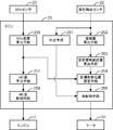
上記ECU25は、CPUやROM及びRAM等からなる周知のマイクロコンピュータで構成されている。ECU25は、上記NOxセンサ23、差圧検出センサ22、及び、エンジン2に取り付けられた各種センサ(図示省略)からの検出信号に基づいて、エンジン2及び制御弁29(電動モータ33)の作動を制御する。
具体的には、ECU25は、図6に示されるように、判定手段251と、堆積量算出手段252と、仮目標制御位置算出手段253と、目標制御位置設定手段254と、弁制御手段255と、NOx濃度算出手段256と、HC量算出手段257と、HC量制御手段258とを備えている。
判定手段251は、フィルタ13の再生が必要か否かを判定する手段であり、本実施形態では、差圧検出センサ22により検出された差圧ΔPが予め設定した第1閾圧力未満であるか否かによって、フィルタ13の再生が必要か否かを判定する。
堆積量算出手段252は、差圧検出センサ22により検出された差圧ΔPに基づいて、フィルタ13に堆積した排気微粒子の量を算出する。ここで、本発明におけるフィルタ13に堆積した排気微粒子の量を検出する堆積量検出手段は、差圧検出センサ22および堆積量算出手段252によって構成される。
仮目標制御位置算出手段253は、堆積量算出手段252によって算出された排気微粒子量に基づいて制御弁29の仮目標制御位置を算出する。
目標制御位置設定手段254は、NOx濃度算出手段256で算出されたNOx濃度に基づいて、仮目標制御位置を修正して、該修正した仮目標制御位置を制御弁29の真の目標制御位置として設定する。
弁制御手段255は、判定手段251による判定結果、および目標制御位置制御手段254によって設定された目標制御位置に基づいて、制御弁29の作動を制御する。具体的には、弁制御手段255は、制御弁29を駆動するモータ33を制御する。
NOx濃度算出手段256は、NOxセンサ23からの検出信号に基づいて、フィルタ13の下流側のNOx濃度を算出する。
HC量算出手段257は、NOx濃度算出手段256によって算出されたNOx濃度に基づいて、NOx触媒部11におけるNOxの還元反応に必要なHC量を算出する。
HC量制御手段258は、HC量算出手段257によって算出されたHC量になるように、エンジン2における燃料の噴射を行うインジェクタ(燃料噴射弁)を制御する。
上記のように構成されたECU25は、差圧検出センサ22により検出された差圧ΔPが予め設定した第1閾圧力未満である場合には、フィルタ13の再生が必要ないと判断して通常運転制御を実行する。具体的には、ECU25は、フィルタ13の再生が必要ないと判断した場合には、制御弁29を通常位置(図3の二点鎖線で示す位置であって、本実施形態では第2通路全閉位置PS2)に制御するとともに、エンジン2の運転状態に基づいてエンジン2から排出される排気中のNOx濃度を推定して、該推定したNOx濃度に基づいてNOx触媒部11におけるNOx還元に必要なHC量を算出し、該算出したHC量を排気中に供給するべくエンジン2の燃焼室内にポスト噴射を行う。このポスト噴射は、圧縮上死点付近のメイン噴射に先立って圧縮工程において行われるものである。
ECU25は、差圧検出センサ22により検出された差圧ΔPが第1閾圧力以上である場合には、フィルタ13の再生が必要と判断して、フィルタ再生制御を実行する。具体的には、ECU25は、フィルタ再生制御が必要と判断した場合には、差圧検出センサ22により検出された差圧ΔPに基づいてフィルタ13に堆積した排気微粒子の量を算出し、該算出した排気微粒子量に基づいて制御弁29の仮目標制御位置を算出する。この仮目標制御位置は、第1通路全閉位置PS1と第2通路全閉位置PS2との間の範囲の位置であって、排気微粒子の堆積量が多くなることに対応して第2通路28に流入する排気流量が増加するようにECU25により予め記憶されたマップデータに基づいて算出される。
そして、ECU25は、上記算出した仮目標制御位置を、NOxセンサ23により検出されたNOx濃度に応じて修正する。本実施形態では、ECU25は、NOxセンサ23により検出されたNOx濃度が高くなることに対応して第1通路27に流入する排気流量が増加するように仮目標制御位置を修正して、該修正した仮目標制御位置を制御弁29の真の目標制御位置として設定する。
ECU25は、上記フィルタ再生制御時には、NOx触媒部11におけるNOx還元に必要なHC量、及び、酸化触媒部12における排気の昇温に必要なHC量を算出し、該算出したHC量を排気中に供給するべくエンジン2の燃焼室内にポスト噴射を行う。
次に、ECU25における通常運転制御及びフィルタ再生制御について、図5のフローチャートに基づいて詳細に説明する。
最初のステップS1では、ECU25は、NOxセンサ23からの濃度信号、差圧検出センサ22からの圧力信号、及びエンジン2に取り付けられた各種センサからの信号を読み込む。
ステップS2では、ECU25は、ステップS1で読み込んだ差圧検出センサ22からの圧力信号に基づいて、フィルタ13の上流側及び下流側の差圧ΔPを算出するとともに、この差圧ΔPが第1閾圧力以上であるか否かを判定し、この判定がNOである場合にはステップS13に進む。一方、判定がYESである場合にはステップS3に進む。
ステップS3では、ECU25は、フィルタ再生制御を開始するべく、ECU25に含まれるROM(図示せず)の内部に記憶されたフィルタ再生用のプログラムを実行する。
ステップS4では、ECU25は、ステップS2で算出した差圧ΔPに基づいて、フィルタ13に堆積した排気微粒子の堆積量(PM堆積量)を算出する。
ステップS5では、ECU25は、ステップS4で算出した排気微粒子の堆積量に基づいて、制御弁29の仮目標制御位置を算出する。
ステップS6では、ECU25は、ステップS1で読み込んだNOxセンサ23からの検出信号に基づいて、フィルタ13の下流側のNOx濃度を算出する。
ステップS7では、ECU25は、ステップS6で算出したNOx濃度に応じて、上記算出した仮目標制御位置を修正して制御弁29の目標制御位置を決定する。
ステップS8では、ECU25は、制御弁29を目標制御位置に制御するべく、電動モータ33に対して必要な制御信号を出力する。
ステップS9では、ECU25は、エンジン2の各種センサからの検出信号に基づいて、NOx触媒部11の上流側における排気中のNOx濃度を算出するとともに、この算出したNOx濃度に基づいて、NOx触媒部11におけるNOxの還元反応に必要なHC量を算出する。さらに、ECU25は、ステップS4で算出した排気微粒子の堆積量に基づいて、該排気微粒子を燃焼除去するために酸化触媒部12において必要なHC量を算出する。エンジン2の運転状態は、ステップS1において読み込んだエンジン2に付属する各センサからの信号に基づいて推定すればよい。
ステップS10では、ECU25は、エンジンのインジェクタ(燃料噴射弁)がメイン噴射を実行するように制御し、その後、エンジン2から排出された直後の排気中(NOx触媒部11の上流側の排気中)のHC量がステップS9で算出したHC量になるように、インジェクタ(燃料噴射弁)に対して必要な制御信号を出力して、インジェクタがポスト噴射を実行するように制御する。
ステップS11では、ECU25は、差圧検出センサ22からの検出信号を読み込んで、現時点における差圧ΔPを算出するとともに、該算出した差圧が第2閾圧力(<第1閾圧力)以下であるか否かを判定し、この判定がNOである場合にはステップS2に戻り、一方、YESである場合にはステップS12に進み、ステップS12では、フィルタ再生制御を終了して、その後、スタートへリターンする。
ステップS2の判定がNOである場合に進むステップS13では、ECU25は、制御弁29を上述の通常位置(第2通路全閉位置PS2)に制御するべく、電動モータ33に対して必要な制御信号を出力する。
ステップS14では、ECU25は、エンジン2の各種センサからの検出信号に基づいて、エンジン2から排出される排気中のNOx濃度を算出(推定)して、この算出したNOx濃度に基づいて、NOx触媒部11におけるNOxの還元反応に必要なHC量を算出する。
ステップS15では、ECU25は、エンジンのインジェクタがメイン噴射するように制御し、その後、エンジン2から排出された直後の排気中のHC量がステップS14で算出したHC量になるように、インジェクタに対して必要な制御信号を出力して、インジェクタがポスト噴射を実行するように制御し、その後、スタートへリターンする。
以上のように構成された排気浄化装置1では、フィルタ13の再生要求がない通常運転時には(ステップS2の判定がNOである場合には)、ECU25がステップS13の処理を実行し、ECU25により制御弁29が通常位置(第2通路全閉位置PS2)に制御される。このため、制御弁29により第2通路28の上流側開口が全閉されて該第2通路28への排気の流入が遮断され、この結果、エンジン2からの排気は全て、第1通路27からNOx触媒部11へと供給された後、酸化触媒部12及びフィルタ13を介して大気中に排出される。一方、フィルタ13の再生要求がある場合には、ECU25がステップS3~ステップS8の処理を実行し、制御弁29はECU25により第1通路全閉位置PS1と第2通路全閉位置PS2との間の目標制御位置に制御される。この結果、エンジン2からの排気は、第1通路27からNOx触媒部11に流入する流れF1(図3参照)と、第2通路28からNOx触媒部11を通らず酸化触媒部12に流入する流れF2(図3参照)とに分岐する。上記第1通路27からNOx触媒部11に流入する排気中のHC成分は、NOx触媒部11におけるNOxの還元反応に利用される。また、上記第2通路28から酸化触媒部12に流入する排気中のHC成分は酸化触媒部12における酸化反応に利用されて、このとき生じる反応熱により排気の昇温が図られる。そして、昇温された排気がフィルタ13に供給されることにより、フィルタ13の温度が目標温度(排気微粒子を燃焼可能な温度)に達して、フィルタに堆積した排気微粒子が燃焼除去される。このように上記実施形態では、フィルタ再生時に酸化触媒部12において必要なHC成分を、第2通路28からNOx触媒部11を介さずに酸化触媒部12に直接、供給するようにしたことで、フィルタ再生時に酸化触媒部12に供給されるHC量を正確に制御することができ、これにより、フィルタ再生に伴う燃費の悪化を防止しながらフィルタ13の再生を確実に実行することができる。
さらに、上記実施形態では、フィルタ再生時には、ECU25がステップS5(及びステップS8)の処理を実行し、上記フィルタ13に堆積した排気微粒子の量が多くなることに対応して第2通路28に流入する排気流量が増加するようにECU25により制御弁29の位置が制御される。これにより、フィルタ13に堆積した排気微粒子の量が多くなることに対応して、第2通路28を介して酸化触媒部12に供給されるHC成分を増加させることができ、その結果、酸化触媒部12におけるHC成分の酸化反応を促進してフィルタ13に供給される排気の温度を高めることができる。よって、フィルタ13に堆積した排気微粒子を、その堆積量に応じて効率良く確実に燃焼除去することができる。
さらに、上記実施形態では、フィルタ再生時には、ECU25がステップS7の処理を実行し、フィルタ13の下流側のNOx濃度に応じて制御弁29の位置が制御される。これにより、フィルタ再生中のNOx浄化率の低下を極力抑制することができる。すなわち、フィルタ再生時には、上述の如く、エンジン2からの排気の一部が第2通路28からNOx触媒部11を通らずに酸化触媒部12に直接流入する。このため、この第2通路28を通過する排気の量が多過ぎると、第1通路27からNOx触媒部11に供給される排気量が減少してフィルタ再生中におけるNOx浄化効率が低下するおそれがある。これに対して、上記実施形態では、フィルタ再生時には、上記NOxセンサ23により検出されたフィルタ13の下流側のNOx濃度が高くなることに対応して、上記第1通路27からNOx触媒部11に流入する排気の流量を増加させて、排気中のNOxの還元反応を促進するようにしたことで、フィルタ再生に伴うNOx浄化性能の低下を極力抑制することができる。
また、上記実施形態では、ECU25は、NOxの還元反応に必要なHC量、及び、フィルタ13の昇温に必要なHC量(酸化触媒部12において必要なHC量)を排気中に供給するために、エンジン2の燃焼室にポスト噴射を行う(ステップS10及びステップS15の処理を実行する)ようにしている。したがって、これらの必要なHC量を確保するために、別途、HC添加装置等を設ける必要もない。よって、部品点数を削減して、排気浄化装置1のコンパクト化及び低コスト化を図ることができる。また、燃料添加装置を設けた場合に必要となる専用配管も不要になるので、燃料漏れ等のトラブルを防止して安全性の向上を図ることができる。
また、油圧ショベル100等の建設機械においては、上述の如く、排気浄化装置1を油圧ポンプ4等の付属機器と共に狭いエンジンルーム3内に収容する必要があるため、乗用車やトラック等に比べてその設置スペースが制限されるが、上記実施形態では、上述のように、燃料添加装置を別途設ける必要がないので、排気浄化装置1を小型化して狭いエンジンルーム3内に効率良く配置することができる。
(他の実施形態)
本発明の構成は、上記実施形態に限定されるものではなく、それ以外の種々の構成を包含するものである。すなわち、上記実施形態では、フィルタ再生時には、制御弁29を第1通路全閉位置PS1と第2通路全閉位置PS2との間の範囲の位置に制御して、第1通路27及び第2通路28の双方にエンジン2からの排気を流入させるようにしているが、これに限ったものではなく、例えば、フィルタ再生時に制御弁29を第1通路全閉位置PS1に制御するようにしてもよい。
本発明の構成は、上記実施形態に限定されるものではなく、それ以外の種々の構成を包含するものである。すなわち、上記実施形態では、フィルタ再生時には、制御弁29を第1通路全閉位置PS1と第2通路全閉位置PS2との間の範囲の位置に制御して、第1通路27及び第2通路28の双方にエンジン2からの排気を流入させるようにしているが、これに限ったものではなく、例えば、フィルタ再生時に制御弁29を第1通路全閉位置PS1に制御するようにしてもよい。
また、上記実施形態では、制御弁29は1つの弁体31を有するものとされているが、これに限ったものではなく、例えば、制御弁29は、第1通路27と第2通路28とをそれぞれ独立に開閉可能な2つの弁体31を有するものであってもよい。
また、上記実施形態では、フィルタ13の再生が必要か否かの判定を、差圧検出センサ22により検出された差圧に基づいて行うようにしているが、これに限ったものではなく、例えば、ECU25において、エンジン2の運転状態(燃焼状態等)の履歴に基づいてフィルタ13に堆積した排気微粒子の量を推定して、この推定した排気微粒子量に基づいてフィルタ13の再生が必要か否かの判定を行うようにしてもよい。また、ECU25においてタイマ制御を実行することにより所定時間ごとにフィルタ13の再生が必要と判定してフィルタ13の再生制御を実行するようにしてもよい。
また、上記実施形態では、NOxセンサ23をフィルタ13の下流側に配設するようにしているが、NOxセンサ23は、NOx触媒部11の下流側であればどこに配設してもよい。また、上記実施形態では、フィルタ13の下流側のNOx濃度をNOxセンサ23により検出するようにしているが、これに限ったものではなく、例えば、ECU25において、各種センサからの検出信号に基づいてエンジン2の運転状態を推定して、該推定した運転状態に基づいて上記NOx濃度を推定(検出)するようにしてもよい。
また、上記実施形態では、NOxの還元に必要なHC量、及びフィルタ13の昇温に必要なHC量を排気中に供給するために、エンジン2の燃焼室にポスト噴射を行うようにしているが、例えば、ポスト噴射に代えてアフター噴射を行うようにしてもよいし、ポスト噴射に加えてさらにアフター噴射を行うようにしてもよい。また、必要なHC量を確保するために、燃料添加装置を別途設けるようにしてもよい。
また、上記実施形態では、排気浄化装置1をディーゼルエンジン2に適用した例を示したが、これに限ったものではなく、例えば、ガソリンエンジンに適用するようにしてもよい。また、エンジン2は直列4気筒エンジンに限らず、水平対向型やV型エンジンであってもよく、気筒数も4気筒に限ったものではなく、例えば3気筒以下や5気筒以上であってもよい。
また、上記実施形態では、NOxを還元するための触媒としてHC-SCR触媒を使用するようにしているが、例えば、NOx吸蔵還元触媒を使用するようにしてもよい。この場合、エンジン2は、ガソリンエンジンであることが好ましい。
また、上記実施形態では、排気浄化装置1を油圧ショベルのエンジン2に適用した例を示したが、これに限ったものではなく、例えば、自動車や船舶のエンジン2に適用するようにしてもよい。
なお、上述した具体的実施形態には以下の構成を有する発明が主に含まれている。
すなわち、本発明の排気浄化装置は、エンジンからの排気が通る排気通路を形成する排気通路形成部材と、上記排気通路に配設され、HCを還元剤として排気中のNOxを還元するNOx触媒部と、上記排気通路における上記NOx触媒部の下流側に配設された酸化触媒部と、上記排気通路における上記酸化触媒部の下流側に配設され、排気中に含まれる排気微粒子を捕集するフィルタと、上記排気通路に設けられた制御弁とを備えており、上記排気通路における上記NOx触媒部の上流側の部分は、上記エンジンからの排気を上記NOx触媒部へと導く第1通路と、上記エンジンからの排気を上記NOx触媒部を介さずに上記酸化触媒部へと導く第2通路とに分岐され、上記制御弁は、上記第1通路に流入する排気の流量と上記第2通路に流入する排気の流量との流量比率を変更する、ことを特徴とする。
本発明では、フィルタの再生が必要な場合には、制御弁の作動(位置)を制御することで、エンジンからの排気の一部(又は全部)を、第2通路に流入させることができる。第2通路に流入した排気流れは、NOx触媒部を通過することなく酸化触媒部に直接供給される。酸化触媒部では、第2通路から供給される排気中のHC成分の酸化反応が促進されて、このとき生じる反応熱によって排気の昇温が図られる。そして、この昇温された排気がフィルタに供給されることで、フィルタ温度が目標温度まで上昇してフィルタに堆積した排気微粒子が燃焼除去される。このように本発明では、フィルタの昇温(フィルタの再生)に必要なHC成分を、第2通路からNOx触媒部を介さずに酸化触媒部に直接、供給することができる。したがって、制御弁が第1通路に流入する排気の流量と第2通路に流入する排気の流量との流量比率を変更することにより、フィルタ再生時に酸化触媒部に供給されるHC量を正確に制御することができる。これにより、燃費の悪化を防止しつつ、フィルタの再生を確実に行うことができる。
また、上記フィルタの再生が必要か否かを判定する判定手段と、上記判定手段による判定結果に基づいて、上記制御弁の作動を制御する弁制御手段とをさらに備えているのが好ましい。
この構成によれば、フィルタの再生が必要か否かを判定する判定手段による判定結果に基づいて、弁制御手段が制御弁の作動を制御することにより、フィルタ再生時に酸化触媒部に供給されるHC量を正確に制御することができる。これにより、燃費の悪化を防止しつつ、フィルタの再生を確実に行うことができる。
さらに、上記弁制御手段は、上記判定手段により上記フィルタの再生が必要ないと判定された場合には、上記制御弁により、上記エンジンからの排気を上記第1及び第2通路のうち1通路にのみ流入させ、一方、上記判定手段により上記フィルタの再生が必要と判定された場合には、上記制御弁により、上記エンジンからの排気を上記第1及び第2通路の双方に流入させるように構成されているのが好ましい。
この構成によれば、上記判定手段によりフィルタの再生が必要ないと判定された場合には、制御弁により上記第2通路への排気の流入が遮断され、これにより、エンジンからの排気を全て第1通路からNOx触媒部を通じて大気中に排出させることができる。したがって、フィルタの再生が必要ない場合には、排気中のNOxをNOx触媒部によって十分に還元して、排気中のNOxの浄化効率を向上させることができる。
一方、上記判定手段により上記フィルタの再生が必要と判定された場合には、上記制御弁により、上記第1及び第2通路の双方への排気の流入が許容されるため、排気の一部を第2通路からNOx触媒を通過させることなく酸化触媒に直接、供給することができ、これにより、フィルタ再生時に酸化触媒部に供給されるHC量を正確に制御することができ、その結果、燃費の悪化を防止しつつ、フィルタの再生を確実に行うことができる。
さらに、上記フィルタに堆積した排気微粒子の量を検出する堆積量検出手段をさらに備え、上記弁制御手段は、上記判定手段により上記フィルタの再生が必要と判定された場合において、上記堆積量検出手段により検出された排気微粒子の堆積量が多くなることに対応して、上記第2通路に流入する排気の流量を増加させるように制御弁の作動を制御するのが好ましい。
この構成によれば、フィルタに堆積した排気微粒子の量が多くなることに対応して、第2通路から酸化触媒部に流入する排気の流量を増加させ、それによって、該排気と共に酸化触媒部に流入するHC量を増加させることができる。したがって、フィルタに堆積した排気微粒子の堆積量が多くなることに対応して、酸化触媒部におけるHC成分の酸化反応を促進して、該酸化触媒部を通ってフィルタに供給される排気の温度を高めることができる。よって、フィルタに堆積した排気微粒子を、その堆積量に応じて効率良く確実に燃焼除去することができる。
さらに、上記NOx触媒部よりも下流側に配設され、排気中のNOx濃度を検出するNOx濃度検出手段をさらに備え、上記弁制御手段は、上記NOx濃度検出手段により検出されたNOx濃度に基づいて、上記制御弁を制御するように構成されているのが好ましい。
この構成によれば、弁制御手段がNOx濃度検出手段により検出されたNOx濃度に基づいて制御弁を制御するので、NOx浄化率の低下を防止しながら、フィルタ再生を効率的に且つ確実に行うことができる。
さらに、上記弁制御手段は、上記判定手段によりフィルタの再生が必要と判定された場合において、上記NOx濃度検出手段により検出されたNOx濃度が高くなることに対応して、上記第1通路に流入する排気の流量を増加させるように上記制御弁を制御するのが好ましい。
この構成によれば、NOx浄化率の低下を防止しながら、フィルタ再生を効率的に且つ確実に行うことができる。
すなわち、フィルタ再生時には、上述の如く、エンジンからの排気の一部(又は全部)が第2通路からNOx触媒部を通らずに酸化触媒部に直接流入する。このため、この第2通路を通過する排気の量が多過ぎると、第1通路からNOx触媒部に供給される排気流量が減少してフィルタ再生中におけるNOx浄化効率が低下するおそれがある。これに対して、上記の構成では、フィルタの再生に際して、NOx濃度検出手段により検出された排気のNOx濃度が高くなることに対応して、上記第1通路からNOx触媒部に流入する排気の流量を増加させるので、フィルタ再生中におけるNOx浄化性能の低下を極力抑制しながら、フィルタ再生を効率良く確実に実行することができる。
さらに、上記エンジンの気筒内に燃料をポスト噴射又はアフター噴射することにより、上記エンジンから排出される排気中のHC量を制御するHC量制御手段をさらに備えているのが好ましい。
この構成によれば、排気中のNOxの還元反応に必要なHC量、及び、フィルタの昇温に必要なHC量(酸化触媒部において必要なHC量)を排気中に供給するために、別途、燃料(HC)添加装置等を設ける必要がないため、装置全体をコンパクト化することができる。
さらに、上記NOx触媒部は、NOx触媒を保持する円筒状のNOx触媒保持体を含み、上記酸化触媒部は、酸化触媒を保持する円筒状の酸化触媒保持体を含み、上記フィルタは円筒状に形成されており、上記NOx触媒保持体、上記酸化触媒保持体、及び上記フィルタは、直列に且つ同軸に配設されているのが好ましい。
この構成によれば、NOx触媒を保持する円筒状のNOx触媒保持体と、酸化触媒を保持する円筒状の酸化触媒保持体と、円筒状のフィルタとが直列に且つ同軸に配置されているので、装置全体をコンパクト化することができる。
本発明は、エンジンの排気浄化装置に有用であり、特に、ショベル等の建設機械に搭載されるエンジンの排気浄化装置に有用である。
1 排気浄化装置
2 エンジン
6 排気浄化装置本体
6a 排気通路下流側部分
7 排気パイプ
7a 排気通路上流側部分
10 排気通路
11 NOx触媒部
12 酸化触媒部
13 フィルタ
14 NOx触媒保持体
15 酸化触媒保持体
22 差圧検出センサ(堆積量検出手段)
23 NOxセンサ(NOx濃度検出手段)
25 ECU
27 第1通路
28 第2通路
29 制御弁
33 モータ
251 判定手段
252 堆積量算出手段(堆積量検出手段)
255 弁制御手段
258 HC量制御手段
2 エンジン
6 排気浄化装置本体
6a 排気通路下流側部分
7 排気パイプ
7a 排気通路上流側部分
10 排気通路
11 NOx触媒部
12 酸化触媒部
13 フィルタ
14 NOx触媒保持体
15 酸化触媒保持体
22 差圧検出センサ(堆積量検出手段)
23 NOxセンサ(NOx濃度検出手段)
25 ECU
27 第1通路
28 第2通路
29 制御弁
33 モータ
251 判定手段
252 堆積量算出手段(堆積量検出手段)
255 弁制御手段
258 HC量制御手段
Claims (8)
- エンジンからの排気が通る排気通路を形成する排気通路形成部材と、
上記排気通路に配設され、HCを還元剤として排気中のNOxを還元するNOx触媒部と、
上記排気通路における上記NOx触媒部の下流側に配設された酸化触媒部と、
上記排気通路における上記酸化触媒部の下流側に配設され、排気中に含まれる排気微粒子を捕集するフィルタと、
上記排気通路に設けられた制御弁と
を備えており、
上記排気通路における上記NOx触媒部の上流側の部分は、上記エンジンからの排気を上記NOx触媒部へと導く第1通路と、上記エンジンからの排気を上記NOx触媒部を介さずに上記酸化触媒部へと導く第2通路とに分岐され、
上記制御弁は、上記第1通路に流入する排気の流量と上記第2通路に流入する排気の流量との流量比率を変更する、
ことを特徴とする排気浄化装置。 - 上記フィルタの再生が必要か否かを判定する判定手段と、
上記判定手段による判定結果に基づいて、上記制御弁の作動を制御する弁制御手段と
をさらに備えている請求項1に記載の排気浄化装置。 - 上記弁制御手段は、上記判定手段により上記フィルタの再生が必要ないと判定された場合には、上記制御弁により、上記エンジンからの排気を上記第1及び第2通路のうち第1通路にのみ流入させ、一方、上記判定手段により上記フィルタの再生が必要と判定された場合には、上記制御弁により、上記エンジンからの排気を上記第1及び第2通路の双方に流入させるように構成されている請求項2に記載の排気浄化装置。
- 上記フィルタに堆積した排気微粒子の量を検出する堆積量検出手段をさらに備え、
上記弁制御手段は、上記判定手段により上記フィルタの再生が必要と判定された場合において、上記堆積量検出手段により検出された排気微粒子の堆積量が多くなることに対応して、上記第2通路に流入する排気の流量を増加させるように上記制御弁の作動を制御する請求項3記載の排気浄化装置。 - 上記フィルタの下流側に配設され、排気中のNOx濃度を検出するNOx濃度検出手段をさらに備え、
上記弁制御手段は、上記NOx濃度検出手段により検出されたNOx濃度に基づいて、上記制御弁の作動を制御するように構成されている請求項2から4のいずれかに記載の排気浄化装置。 - 上記弁制御手段は、上記判定手段により上記フィルタの再生が必要と判定された場合において、上記NOx濃度検出手段により検出されたNOx濃度が高くなることに対応して、上記第1通路に流入する排気の流量を増加させるように上記制御弁を制御する請求項5に記載の排気浄化装置。
- 上記エンジンの気筒内に燃料をポスト噴射又はアフター噴射することにより、上記エンジンから排出される排気中のHC量を制御するHC量制御手段をさらに備えている請求項1から6のいずれかに記載の排気浄化装置。
- 上記NOx触媒部は、NOx触媒を保持する円筒状のNOx触媒保持体を含み、
上記酸化触媒部は、酸化触媒を保持する円筒状の酸化触媒保持体を含み、
上記フィルタは円筒状に形成されており、
上記NOx触媒保持体、上記酸化触媒保持体、及び上記フィルタは、直列に且つ同軸に配設されている請求項1から7のいずれかに記載の排気浄化装置。
Applications Claiming Priority (2)
| Application Number | Priority Date | Filing Date | Title |
|---|---|---|---|
| JP2011079697A JP2012215083A (ja) | 2011-03-31 | 2011-03-31 | 排気浄化装置 |
| JP2011-079697 | 2011-03-31 |
Publications (1)
| Publication Number | Publication Date |
|---|---|
| WO2012132227A1 true WO2012132227A1 (ja) | 2012-10-04 |
Family
ID=46930023
Family Applications (1)
| Application Number | Title | Priority Date | Filing Date |
|---|---|---|---|
| PCT/JP2012/001357 Ceased WO2012132227A1 (ja) | 2011-03-31 | 2012-02-28 | 排気浄化装置 |
Country Status (2)
| Country | Link |
|---|---|
| JP (1) | JP2012215083A (ja) |
| WO (1) | WO2012132227A1 (ja) |
Citations (4)
| Publication number | Priority date | Publication date | Assignee | Title |
|---|---|---|---|---|
| JP2002021544A (ja) * | 2000-05-12 | 2002-01-23 | Dmc 2 Degussa Metals Catalysts Cerdec Ag | 内燃機関の希薄排ガスから窒素酸化物およびカーボンブラック粒子を除去するための方法および排ガス浄化装置 |
| JP2002349236A (ja) * | 2001-05-25 | 2002-12-04 | Hino Motors Ltd | エンジンの排ガス浄化装置 |
| JP2008121493A (ja) * | 2006-11-10 | 2008-05-29 | Hino Motors Ltd | 排気浄化装置 |
| JP2011043160A (ja) * | 2009-08-21 | 2011-03-03 | Hyundai Motor Co Ltd | ディーゼル自動車の排気装置 |
-
2011
- 2011-03-31 JP JP2011079697A patent/JP2012215083A/ja not_active Withdrawn
-
2012
- 2012-02-28 WO PCT/JP2012/001357 patent/WO2012132227A1/ja not_active Ceased
Patent Citations (4)
| Publication number | Priority date | Publication date | Assignee | Title |
|---|---|---|---|---|
| JP2002021544A (ja) * | 2000-05-12 | 2002-01-23 | Dmc 2 Degussa Metals Catalysts Cerdec Ag | 内燃機関の希薄排ガスから窒素酸化物およびカーボンブラック粒子を除去するための方法および排ガス浄化装置 |
| JP2002349236A (ja) * | 2001-05-25 | 2002-12-04 | Hino Motors Ltd | エンジンの排ガス浄化装置 |
| JP2008121493A (ja) * | 2006-11-10 | 2008-05-29 | Hino Motors Ltd | 排気浄化装置 |
| JP2011043160A (ja) * | 2009-08-21 | 2011-03-03 | Hyundai Motor Co Ltd | ディーゼル自動車の排気装置 |
Also Published As
| Publication number | Publication date |
|---|---|
| JP2012215083A (ja) | 2012-11-08 |
Similar Documents
| Publication | Publication Date | Title |
|---|---|---|
| EP2261489B1 (en) | Method for controlling exhaust gas purification system and exhaust gas purification system | |
| KR101251505B1 (ko) | 질소산화물 저감 촉매에 저장되는 질소산화물의 양을 예측하는 방법 및 이를 이용한 배기 장치 | |
| JP4798511B2 (ja) | NOx浄化装置の診断装置 | |
| JP4475271B2 (ja) | NOxセンサの異常診断装置及び異常診断方法 | |
| WO2007060785A1 (ja) | 排気ガス浄化システムの制御方法及び排気ガス浄化システム | |
| JP4178960B2 (ja) | 内燃機関の排気浄化装置 | |
| JP3979437B1 (ja) | 排気ガス浄化システムの制御方法及び排気ガス浄化システム | |
| JP5093672B2 (ja) | NOxセンサの劣化判定制御装置及び劣化回復制御装置 | |
| JP4140640B2 (ja) | 排気ガス浄化方法及び排気ガス浄化システム | |
| JP2011226312A (ja) | 排気ガス浄化装置及び排気ガス浄化装置の制御方法 | |
| JP5092511B2 (ja) | NOx浄化システム及びNOx浄化システムの制御方法 | |
| JP2008240577A (ja) | 酸化触媒の劣化診断装置及び劣化診断方法 | |
| US7614219B2 (en) | Exhaust gas purifying apparatus for internal combustion engine | |
| JP4276472B2 (ja) | 内燃機関の触媒劣化判定装置 | |
| WO2014102932A1 (ja) | 内燃機関の排気浄化システム | |
| JP4449947B2 (ja) | 内燃機関の制御装置 | |
| CN114673579B (zh) | 内燃机的排气净化装置 | |
| JP2010209737A (ja) | 内燃機関の排気浄化装置 | |
| JP2010249076A (ja) | 内燃機関の排気浄化装置 | |
| JP2006063970A (ja) | 内燃機関の排気浄化装置 | |
| JP5569690B2 (ja) | 内燃機関の排気浄化装置 | |
| JP2010185434A (ja) | 内燃機関の排気浄化装置 | |
| WO2012132233A1 (ja) | 排気浄化装置 | |
| JP2007071080A (ja) | 内燃機関用排出ガス浄化装置 | |
| JP2013253540A (ja) | 内燃機関の排気浄化システム |
Legal Events
| Date | Code | Title | Description |
|---|---|---|---|
| 121 | Ep: the epo has been informed by wipo that ep was designated in this application |
Ref document number: 12764055 Country of ref document: EP Kind code of ref document: A1 |
|
| NENP | Non-entry into the national phase |
Ref country code: DE |
|
| 122 | Ep: pct application non-entry in european phase |
Ref document number: 12764055 Country of ref document: EP Kind code of ref document: A1 |