WO2012128460A2 - 홍합유래 고분자를 이용한 분리막 코팅제 및 그 제조방법, 열수축 방지제 및 그 제조방법 - Google Patents
홍합유래 고분자를 이용한 분리막 코팅제 및 그 제조방법, 열수축 방지제 및 그 제조방법 Download PDFInfo
- Publication number
- WO2012128460A2 WO2012128460A2 PCT/KR2012/000455 KR2012000455W WO2012128460A2 WO 2012128460 A2 WO2012128460 A2 WO 2012128460A2 KR 2012000455 W KR2012000455 W KR 2012000455W WO 2012128460 A2 WO2012128460 A2 WO 2012128460A2
- Authority
- WO
- WIPO (PCT)
- Prior art keywords
- separator
- resin
- secondary battery
- present
- preventing heat
- Prior art date
- Legal status (The legal status is an assumption and is not a legal conclusion. Google has not performed a legal analysis and makes no representation as to the accuracy of the status listed.)
- Ceased
Links
Images


Classifications
-
- H—ELECTRICITY
- H01—ELECTRIC ELEMENTS
- H01M—PROCESSES OR MEANS, e.g. BATTERIES, FOR THE DIRECT CONVERSION OF CHEMICAL ENERGY INTO ELECTRICAL ENERGY
- H01M50/00—Constructional details or processes of manufacture of the non-active parts of electrochemical cells other than fuel cells, e.g. hybrid cells
- H01M50/40—Separators; Membranes; Diaphragms; Spacing elements inside cells
- H01M50/489—Separators, membranes, diaphragms or spacing elements inside the cells, characterised by their physical properties, e.g. swelling degree, hydrophilicity or shut down properties
-
- H—ELECTRICITY
- H01—ELECTRIC ELEMENTS
- H01M—PROCESSES OR MEANS, e.g. BATTERIES, FOR THE DIRECT CONVERSION OF CHEMICAL ENERGY INTO ELECTRICAL ENERGY
- H01M50/00—Constructional details or processes of manufacture of the non-active parts of electrochemical cells other than fuel cells, e.g. hybrid cells
- H01M50/40—Separators; Membranes; Diaphragms; Spacing elements inside cells
- H01M50/409—Separators, membranes or diaphragms characterised by the material
- H01M50/411—Organic material
- H01M50/414—Synthetic resins, e.g. thermoplastics or thermosetting resins
-
- H—ELECTRICITY
- H01—ELECTRIC ELEMENTS
- H01M—PROCESSES OR MEANS, e.g. BATTERIES, FOR THE DIRECT CONVERSION OF CHEMICAL ENERGY INTO ELECTRICAL ENERGY
- H01M50/00—Constructional details or processes of manufacture of the non-active parts of electrochemical cells other than fuel cells, e.g. hybrid cells
- H01M50/40—Separators; Membranes; Diaphragms; Spacing elements inside cells
- H01M50/409—Separators, membranes or diaphragms characterised by the material
- H01M50/411—Organic material
- H01M50/414—Synthetic resins, e.g. thermoplastics or thermosetting resins
- H01M50/417—Polyolefins
-
- H—ELECTRICITY
- H01—ELECTRIC ELEMENTS
- H01M—PROCESSES OR MEANS, e.g. BATTERIES, FOR THE DIRECT CONVERSION OF CHEMICAL ENERGY INTO ELECTRICAL ENERGY
- H01M50/00—Constructional details or processes of manufacture of the non-active parts of electrochemical cells other than fuel cells, e.g. hybrid cells
- H01M50/40—Separators; Membranes; Diaphragms; Spacing elements inside cells
- H01M50/409—Separators, membranes or diaphragms characterised by the material
- H01M50/411—Organic material
- H01M50/414—Synthetic resins, e.g. thermoplastics or thermosetting resins
- H01M50/42—Acrylic resins
-
- H—ELECTRICITY
- H01—ELECTRIC ELEMENTS
- H01M—PROCESSES OR MEANS, e.g. BATTERIES, FOR THE DIRECT CONVERSION OF CHEMICAL ENERGY INTO ELECTRICAL ENERGY
- H01M50/00—Constructional details or processes of manufacture of the non-active parts of electrochemical cells other than fuel cells, e.g. hybrid cells
- H01M50/40—Separators; Membranes; Diaphragms; Spacing elements inside cells
- H01M50/409—Separators, membranes or diaphragms characterised by the material
- H01M50/411—Organic material
- H01M50/414—Synthetic resins, e.g. thermoplastics or thermosetting resins
- H01M50/423—Polyamide resins
-
- H—ELECTRICITY
- H01—ELECTRIC ELEMENTS
- H01M—PROCESSES OR MEANS, e.g. BATTERIES, FOR THE DIRECT CONVERSION OF CHEMICAL ENERGY INTO ELECTRICAL ENERGY
- H01M50/00—Constructional details or processes of manufacture of the non-active parts of electrochemical cells other than fuel cells, e.g. hybrid cells
- H01M50/40—Separators; Membranes; Diaphragms; Spacing elements inside cells
- H01M50/409—Separators, membranes or diaphragms characterised by the material
- H01M50/411—Organic material
- H01M50/414—Synthetic resins, e.g. thermoplastics or thermosetting resins
- H01M50/426—Fluorocarbon polymers
-
- H—ELECTRICITY
- H01—ELECTRIC ELEMENTS
- H01M—PROCESSES OR MEANS, e.g. BATTERIES, FOR THE DIRECT CONVERSION OF CHEMICAL ENERGY INTO ELECTRICAL ENERGY
- H01M50/00—Constructional details or processes of manufacture of the non-active parts of electrochemical cells other than fuel cells, e.g. hybrid cells
- H01M50/40—Separators; Membranes; Diaphragms; Spacing elements inside cells
- H01M50/409—Separators, membranes or diaphragms characterised by the material
- H01M50/411—Organic material
- H01M50/429—Natural polymers
-
- H—ELECTRICITY
- H01—ELECTRIC ELEMENTS
- H01M—PROCESSES OR MEANS, e.g. BATTERIES, FOR THE DIRECT CONVERSION OF CHEMICAL ENERGY INTO ELECTRICAL ENERGY
- H01M50/00—Constructional details or processes of manufacture of the non-active parts of electrochemical cells other than fuel cells, e.g. hybrid cells
- H01M50/40—Separators; Membranes; Diaphragms; Spacing elements inside cells
- H01M50/409—Separators, membranes or diaphragms characterised by the material
- H01M50/449—Separators, membranes or diaphragms characterised by the material having a layered structure
-
- H—ELECTRICITY
- H01—ELECTRIC ELEMENTS
- H01M—PROCESSES OR MEANS, e.g. BATTERIES, FOR THE DIRECT CONVERSION OF CHEMICAL ENERGY INTO ELECTRICAL ENERGY
- H01M50/00—Constructional details or processes of manufacture of the non-active parts of electrochemical cells other than fuel cells, e.g. hybrid cells
- H01M50/40—Separators; Membranes; Diaphragms; Spacing elements inside cells
- H01M50/409—Separators, membranes or diaphragms characterised by the material
- H01M50/449—Separators, membranes or diaphragms characterised by the material having a layered structure
- H01M50/451—Separators, membranes or diaphragms characterised by the material having a layered structure comprising layers of only organic material and layers containing inorganic material
-
- H—ELECTRICITY
- H01—ELECTRIC ELEMENTS
- H01M—PROCESSES OR MEANS, e.g. BATTERIES, FOR THE DIRECT CONVERSION OF CHEMICAL ENERGY INTO ELECTRICAL ENERGY
- H01M50/00—Constructional details or processes of manufacture of the non-active parts of electrochemical cells other than fuel cells, e.g. hybrid cells
- H01M50/40—Separators; Membranes; Diaphragms; Spacing elements inside cells
- H01M50/409—Separators, membranes or diaphragms characterised by the material
- H01M50/449—Separators, membranes or diaphragms characterised by the material having a layered structure
- H01M50/454—Separators, membranes or diaphragms characterised by the material having a layered structure comprising a non-fibrous layer and a fibrous layer superimposed on one another
-
- H—ELECTRICITY
- H01—ELECTRIC ELEMENTS
- H01M—PROCESSES OR MEANS, e.g. BATTERIES, FOR THE DIRECT CONVERSION OF CHEMICAL ENERGY INTO ELECTRICAL ENERGY
- H01M50/00—Constructional details or processes of manufacture of the non-active parts of electrochemical cells other than fuel cells, e.g. hybrid cells
- H01M50/40—Separators; Membranes; Diaphragms; Spacing elements inside cells
- H01M50/489—Separators, membranes, diaphragms or spacing elements inside the cells, characterised by their physical properties, e.g. swelling degree, hydrophilicity or shut down properties
- H01M50/491—Porosity
-
- H—ELECTRICITY
- H01—ELECTRIC ELEMENTS
- H01M—PROCESSES OR MEANS, e.g. BATTERIES, FOR THE DIRECT CONVERSION OF CHEMICAL ENERGY INTO ELECTRICAL ENERGY
- H01M10/00—Secondary cells; Manufacture thereof
- H01M10/05—Accumulators with non-aqueous electrolyte
- H01M10/052—Li-accumulators
- H01M10/0525—Rocking-chair batteries, i.e. batteries with lithium insertion or intercalation in both electrodes; Lithium-ion batteries
-
- Y—GENERAL TAGGING OF NEW TECHNOLOGICAL DEVELOPMENTS; GENERAL TAGGING OF CROSS-SECTIONAL TECHNOLOGIES SPANNING OVER SEVERAL SECTIONS OF THE IPC; TECHNICAL SUBJECTS COVERED BY FORMER USPC CROSS-REFERENCE ART COLLECTIONS [XRACs] AND DIGESTS
- Y02—TECHNOLOGIES OR APPLICATIONS FOR MITIGATION OR ADAPTATION AGAINST CLIMATE CHANGE
- Y02E—REDUCTION OF GREENHOUSE GAS [GHG] EMISSIONS, RELATED TO ENERGY GENERATION, TRANSMISSION OR DISTRIBUTION
- Y02E60/00—Enabling technologies; Technologies with a potential or indirect contribution to GHG emissions mitigation
- Y02E60/10—Energy storage using batteries
Definitions
- the present invention relates to a membrane coating agent using a mussel-derived polymer, a method for manufacturing the same, a heat shrink prevention agent, and a method for manufacturing the same, and more particularly, a compatibility with an electrolyte and a low contact angle without damaging pores of the membrane substrate in a relatively simple process.
- the present invention using a mussel-derived polymer capable of producing a high output battery and a high capacity battery by improving the impregnating ability of the electrolyte by improving the surface properties of the present invention, and further preventing the heat shrinkage of the separator is a membrane coating agent using the mussel-derived polymer. And a method for producing the same, a heat shrink preventing agent and a method for producing the same.
- the lithium secondary battery is manufactured by using a metal oxide such as LiCoO 2 as a cathode active material and a carbon material as a cathode active material, a porous separator between the anode and the cathode, and a non-aqueous electrolyte having a lithium salt such as LiPF 6 . .
- lithium ions of the positive electrode active material are released and inserted into the carbon layer of the negative electrode, and during discharge, lithium ions of the negative electrode carbon layer are released and inserted into the positive electrode active material, wherein the non-aqueous electrolyte solution is lithium ions between the negative electrode and the positive electrode. It acts as a medium for moving the.
- a lithium secondary battery should basically be stable in the operating voltage range of the battery and have a performance capable of transferring ions at a sufficiently high speed.
- the porous separator is a 10-30 ⁇ m thick polymer membrane having a porous structure located between the positive electrode and the negative electrode, and isolates the positive electrode and the negative electrode, and prevents an electrical short circuit between the two poles. It serves to pass.
- the separator itself does not electrochemically participate in the battery reaction, but affects battery performance and safety due to physical properties such as wettability with the electrolyte and degree of microporosity.
- a non-aqueous organic solvent such as ethylene carbonate, dimethyl carbonate, diethyl carbonate, and propylene carbonate is mainly used as the non-aqueous electrolyte mainly used in the secondary battery.
- These electrolytes are polar solvents that are polar enough to effectively dissolve and dissociate electrolyte salts, and are aprotic solvents without active hydrogen, and are often high in viscosity and surface tension due to extensive interactions within the electrolyte.
- the electrolyte has a low affinity with an electrolyte having a hydrophilic property. It has a low content characteristic, which results in increasing the overall resistance of the battery, there is a problem in that it is not suitable for high output, high capacity battery by the continuous reduction of capacity and high rate charge-discharge characteristics according to the cycle.
- the general porous membrane is poor in water permeability compared to the hydrophilic material, even if the membrane having the same pore ( ⁇ ) due to the unique hydrophobic properties. Therefore, it is necessary to hydrophilize the surface of the hydrophobic material to increase its water permeability.
- Korean Patent Publication No. 2008-0106870 discloses a method of coating the surface of the hydrophobic polymer membrane with a hydrophilic polymer, and Korean Patent Publication No.
- 2008-0061049 discloses hydrophilization of the surface of the hydrophobic polymer membrane, but in terms of practical technology through Hydrophilization into the internal pores is quite difficult, and due to the problem of high cost, the actual commercialization is difficult.
- electrochemical devices such as lithium secondary batteries have problems not only with the above-described safety problems but also with the separators currently used.
- currently produced lithium secondary batteries and lithium ion polymer batteries generally use a polyolefin-based separator to prevent short circuit between the positive electrode and the negative electrode.
- polyolefin-based membranes have their original size at a high temperature due to the properties of the membrane material, for example, the characteristics and processing characteristics of the polyolefin-based melt, usually at 200 or less, and the stretching process to control pore size and porosity. It has the disadvantage of heat shrinking. Therefore, when the battery rises to a high temperature due to internal / external stimulation, it is more likely that the positive electrode and the negative electrode are shorted to each other due to shrinkage or melting of the separator, and thus, the battery may show a great risk of explosion due to the release of electrical energy. do. Therefore, it is essential to develop a membrane that does not undergo heat shrinkage at high temperatures.
- the present invention has been made to solve the above problems and to solve the technical problem that is required in the prior art, the problem to be solved by the present invention is a hydrophilic membrane in a simple method without damaging the pores of the hydrophobic porous membrane It is to provide a separator coating agent and a method for manufacturing the same, a separator comprising the same, a method for producing the same and an electrochemical device including the same.
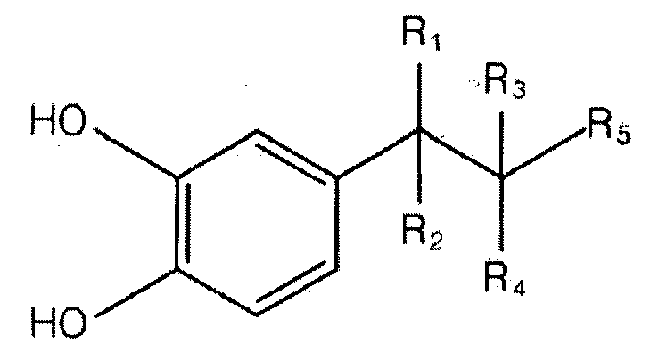
- the present invention is a method for preparing a separator coating comprising a compound of Formula 1, wherein the method comprises the step of dissolving the compound of Formula 1 in a solution of pH 7 to 11 It provides a method for producing a coating.
- R 1 , R 2 , R 3 , R 4 and R 5 is thiol, primary amine, secondary amine, nitrile, aldehyde, respectively. , Imidazole, azide, halide, polyhexamethylene dithiocarbonate, hydroxyl, carboxylic acid, carboxylic ester ) Or one selected from the group consisting of carboxamides, and R 1 , R 2 , R 3 , R 4 and R 5 except hydrogen are hydrogen)
- the compound causes a polymerization reaction at a pH of 7 or more
- the separator is a separator for an electrochemical device
- the electrochemical device may be a secondary battery or a capacitor.
- the present invention also provides a separator coating prepared according to the method described above. '
- the present invention is a separator, the separator is a porous substrate; And it provides a separator characterized in that it comprises a compound of formula 1 coated on the surface or inside of the porous substrate.
- R 1 , R 2 , R 3 , R 4 and R 5 is thiol, primary amine, secondary amine, nitrile, aldehyde, respectively. , Imidazole, azide, halide, polyhexamethylene dithiocarbonate, hydroxyl, carboxylic acid, carboxylic ester ) Or one selected from the group consisting of carboxamides, and R 1 , R 2 , R 3 , R 4 and R 5 except hydrogen are hydrogen)
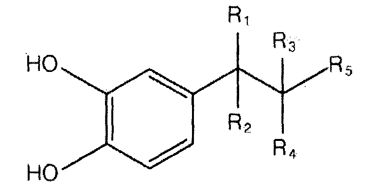
- the present invention also provides a method for preventing heat shrinkage of a polyolefin separator of a lithium secondary battery, wherein the method includes coating a polymer polymerized with the compound of Formula 1 on the polyolefin separator to a polyolefin separator of a lithium secondary battery.
- the method includes coating a polymer polymerized with the compound of Formula 1 on the polyolefin separator to a polyolefin separator of a lithium secondary battery.
- R 1 , R 2 , R 3 , R 4 and R 5 is thiol, primary amine, secondary amine, nitrile, aldehyde, respectively. , Imidazole, azide, halide, polyhexamethylene dithiocarbonate, hydroxyl, carboxylic acid, carboxylic ester ) Or one selected from the group consisting of carboxamides, and R 1 , R 2 , R 3 , R 4 and R 5 except hydrogen are hydrogen)
- the present invention is also a method for preventing heat shrinkage of a polyolefin separator of a lithium secondary battery.
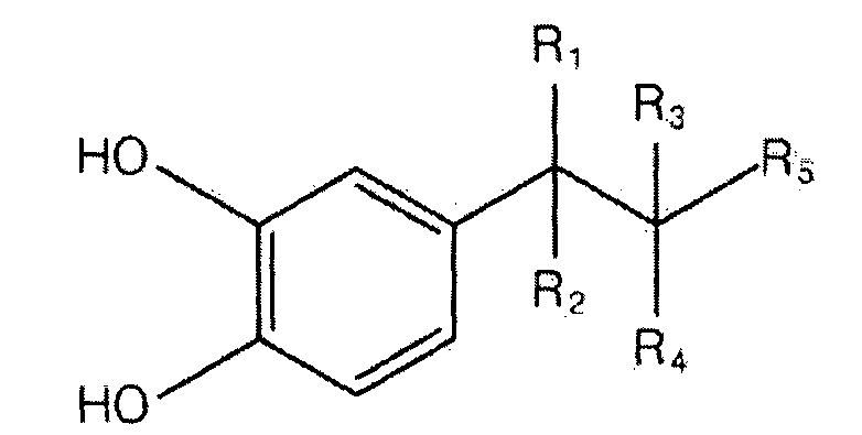
- R 1 , R 2 , R 3 , R 4 and R 5 is thiol, primary amine, secondary amine, nitrile, aldehyde, respectively. , Imidazole, azide, halide, polyhexamethylene dithiocarbonate, hydroxyl, carboxylic acid, carboxylic ester ) Or one selected from the group consisting of carboxamides, and R 1 , R 2 , R 3 , R 4 and R 5 except hydrogen are hydrogen)
- the present invention can improve the surface properties such as compatibility with the electrolyte and low contact angle without damaging the pores of the membrane substrate by a simple process. Therefore, through this, the impregnation ability of the electrolyte is improved, and there is an advantage that the production of a high output battery and a high capacity battery is possible.
- FIG. 1 is a schematic diagram of a method for producing a porous polyethylene separator coated with polydopamine according to an embodiment of the present invention.
- Figure 2 is a schematic diagram of the polymerization mechanism (mechanism) of the polydopamine polymer formed from dopamine in accordance with an embodiment of the present invention.
- Figure 4 is a SEM photograph of the surface of the porous polyethylene separator prepared in Comparative Example and Example.
- FIG. 7 is a DSC result of measuring thermal properties of polyethylene separators prepared in Comparative Examples and Examples (DSC, heating rate: 10 ° C./min).
- FIG. 12 is a photograph of the polyethylene membrane exposed to a high temperature environment according to the embodiment and the comparative example of the membrane coated mussel-derived polymer according to the present invention.
- the electrochemical device used in the present invention is based on the anode / cathode, and includes all of any device including an electrolyte and a separator, for example, a secondary battery, a capacitor and the like.
- the microporous separator which is mainly used as a separator for a secondary battery, which is an electrochemical device, has a problem in that the impregnation ability of the electrolyte is poor due to the hydrophobic surface characteristic, making it unsuitable for high output and high capacity secondary batteries. Therefore, the present invention uses a mussel-derived polymer as a coating agent to improve the surface properties on the surface of the conventional microporous separator substrate, and by coating this, the impregnating ability of the electrolyte is improved to implement a secondary battery capable of high output and high capacity.
- mussels Since mussels produce and secrete special water-insoluble adhesives, mussels have been studied as potential raw materials for effective water-resistant bio-adhesives. Mussels are firmly attached to the surface of the water through a squeegee that extends from the foot, and the ends of each stool contain a water-resistant adhesive that allows the adhesive plaque to be fixed to a wet solid surface (Waite et al., Biology Review 58: 209-231 (1983). In addition, mussel-derived adhesive polymers are harmless to humans and do not cause an immune response, and thus may be used as adhesives for medical use (Dove et al., Journal of American Dental Association. 112: 879 (1986)).
- the present invention uses such a mussel-derived polymer as a membrane coating agent, thereby improving both the containing properties and the wettability of the electrolyte.
- Formula 1 is a chemical structure of the membrane coating agent using the mussel-derived polymer according to the present invention.
- R 1 , R 2 , R 3 , R 4, and R 5 may be a thiol, a primary amine, a second amine, a nitrile, or an aldehyde, respectively.
- the present invention provides a hydrophilic property to the separator without damaging the pores of the hydrophobic porous separator by coating a coating agent, such as the formula (1) in a simple method.
- a coating agent such as the formula (1)
- the method of manufacturing a hydrophilized porous separator capable of producing a high output battery and a high capacity battery by improving the impregnation ability of the electrolyte by improving the surface properties such as compatibility with the electrolyte and a low contact angle, and a separator for a lithium secondary battery, and The used lithium secondary battery can be provided.
- the membrane coating agent according to the present invention comprises a distilled water-based buffer and the compound represented by the formula (1), alcohol, such as methanol may be optionally added according to the description of the porous membrane.
- alcohol such as methanol
- the compound represented by Chemical Formula 1 is a dopamine-based material, and the dopamine-based material is spontaneously polymerized into polydopamine, a mussel-derived polymer, in a weak base environment (pH 8.5). Form a thin polymer layer on the surface of the, the coating thickness of the separator may range from 0.001 to 1 ⁇ m.
- the polydopamine formed in the separator according to the present invention not only possesses excellent chemical stability, but also effectively converts the hydrophobic surface property into hydrophilicity without damaging the pores of the microporous membrane substrate due to the thin polymer coating thickness of about 50 nm. You can expect. Dopamine was also used in a cheap and environmentally friendly distilled water-based buffer (10 mM tris buffer solution, pH 8.5) in place of expensive and environmentally harmful everyday organic solvents. This is because in order to form a polydopamine coating layer, which is a mussel-derived polymer, the solution must be kept at a weak base (pH 8.5).
- the porous substrate of the separator according to the present invention is an olefin resin, a fluorine resin, a polyester resin, a cellulose resin, a polyamide resin, a polyimide resin, a polysulfone resin, a polyacrylonitrile resin, a polyacetal system Resin, polycarbonate-based resin, vinylidene fluoride-based resin, glass fiber to the inorganic composite may be in the form of a single or multiple layers, the pore size of the porous substrate is in the range of 0.001 to 1000 ⁇ m, porosity is 5 to 95% Range, thickness may range from 1 to 1000 ⁇ m.
- a porous polyethylene membrane Asahi Kasei, 20 ⁇ m, porosity: 40%
- Figure 1 is a schematic diagram of a manufacturing procedure of the hydrophilic membrane of the present invention.
- a porous membrane having a hydrophilic property may be obtained.
- the impregnation method may be a variety of methods such as pressure coating method, spin coating method, spray method or roller coating method in addition to the general immersion coating method, all belong to the scope of the present invention.
- Figure 2 shows the chemical reaction characteristics occurring in the membrane coating using dopamine.
- the membrane coating agent using the dopamine may be spontaneous polymerization reaction under weak base conditions (pH 8.5) to form a polydopamine polymer derived from mussels. Therefore, the pH condition of the solution in which the compound of Formula 1 is dissolved according to the present invention is preferably 7 to 11, and more preferably 7 to 9, which is a weak base condition in which the compound of Formula 1 is spontaneously polymerized.
- Porous polyethylene membrane (Asahi Kasei, 20 ⁇ m, porosity: 40%) was washed once with acetone and dried for 24 hours in a vacuum oven at room temperature.
- the resulting polydopamine polymer is coated on the surface of the membrane substrate impregnated with the membrane coating agent.
- the surface of the membrane substrate impregnated with the membrane coating agent using dopamine has a dark brown color.
- the polydopamine coating is known to be formed in a very thin thickness, it can be confirmed through the comparative example and the example of FIG. 4 that the coating was effectively coated without pore damage of the microporous membrane substrate.
- XPS of the membrane surface was measured in order to confirm the presence of the coating of polydopamine in detail, and as shown in FIG. 5, new nitrogen (N1s) and oxygen (O1s) peaks, which were not present in the comparative example, were generated in Examples. It could be confirmed.
- the porous membrane coated with the polydopamine polymer according to the present invention has the inherent mechanical strength (Instron, tensile rate: 1 cm / min) and pyrolysis characteristics (DSC, heating) of the existing porous membrane substrate. Rate: 10 ° C / min) was confirmed that not inhibited.
- the porous separator coated with the polydopamine polymer according to the present invention effectively provides the hydrophilic surface property to the conventional porous separator of the hydrophobic surface property.
- the conventional hydrophobic porous membrane exhibits a contact angle of 108 °, but the contact angle of the separator according to the present invention was 39 °, the contact angle was greatly reduced (contact angle between the droplet and the membrane substrate, 0.5 ⁇ l ).
- Table 1 shows the characteristics change of the separator according to the polydopamine coating, referring to this, it can be seen that the porous membrane coated with the polydopamine polymer according to the present invention shows an improved electrolyte impregnation amount and ion conductivity compared to the conventional porous separator have.
- the present invention also provides an electrochemical cell consisting of an electrode assembly wherein the porous separator is interposed between an anode and a cathode, the electrochemical cell provides electricity through an electrochemical reaction, for example, it may be an electrochemical secondary battery or an electrochemical capacitor.
- Figure 11 shows the output characteristics of the secondary battery, for charging the lithium secondary battery with a current value of 1C for output characteristics analysis, 10 cycles at a current value of 1C, 3C, 6C, 9C, 12C, 15C, 1C Discharged.
- the porous separator coated with the polydopamine polymer according to the present invention showed significantly improved output characteristics compared to the conventional porous separator. This is thought to be due to the excellent ionic conductivity retention by reducing electrolyte leakage at high rate driving due to the improved compatibility and wettability with the electrolyte as mentioned above.
- the porous membrane coated with the polydopamine polymer according to the present invention may bring variety in selecting an electrolyte solution.
- the present invention has discovered a new effect that the mussel-derived polymer according to the above-described method acts as a heat shrink inhibitor of the separator, which will be described through the following experimental example.
- Porous polyethylene membranes (Asahi Kasei, 20, porosity: 40%) that were not surface treated with polydopamine were stored at 140 for 1 hour at high temperature.
- FIG. 12 is a photograph of the polyethylene membrane exposed to a high temperature environment according to the embodiment and the comparative example of the membrane coated mussel-derived polymer according to the present invention.
- d is less shrunk in the separator of the polydopamine-coated example than the comparative example separator on the right side.
- the degree of shrinkage of the polyolefin separator coated with polydopamine is about half that of the uncoated separator.
- the present invention generates a heat shrinkage prevention effect by coating the mussel-derived polymer on the surface of the separator as described above.
Landscapes
- Chemical & Material Sciences (AREA)
- Chemical Kinetics & Catalysis (AREA)
- Electrochemistry (AREA)
- General Chemical & Material Sciences (AREA)
- Inorganic Chemistry (AREA)
- Cell Separators (AREA)
- Manufacture Of Porous Articles, And Recovery And Treatment Of Waste Products (AREA)
Abstract
홍합유래 고분자 코팅을 이용한 친수화된 다공성 분리막의 제조방법 및 이를 포함하는 전기화학 셀을 제공한다. 본 발명에 따른 폴리도파민이 코팅된 다공성 분리막은 제조공정이 친환경적이며 경제적일 뿐만 아니라, 코팅된 고분자가 분리막의 기공을 손상시키지 않으면서 효과적으로 친수성을 부여함으로써, 전해액과의 상용성 및 젖음성 향상을 통해 전해액의 함침능력을 향상시켜 고출력전지와 고용량전지의 생산이 가능할 수 있다.
Description
본 발명은 홍합유래 고분자를 이용한 분리막 코팅제 및 그 제조방법, 열수축 방지제 및 그 제조방법에 관한 것으로, 보다 상세하게는 비교적 단순한 공정으로 분리막 기재의 기공을 손상시키지 않으면서 전해액과의 상용성 및 낮은 접촉각 등의 표면 특성 향상을 통해 전해액의 함침 능력을 향상시켜 고출력전지와 고용량전지의 생산이 가능하고, 더 나아가 분리막의 열수축을 방지할 수 있는 홍합유래 고분자를 이용한 본 발명은 홍합유래 고분자를 이용한 분리막 코팅제 및 그 제조방법, 열수축 방지제 및 그 제조방법에 관한 것이다.
최근 이동통신 및 휴대용 전자기기의 사용이 지속적으로 증가되어지고 휴대용 전자기기의 급속한 발전에 따라 이차전지의 수요는 점차 증대되고 있으며 이들에 요구되는 기능 또한 다변화 되어 이들의 전원을 유지할 수 있는 이차전지의 경량화, 소형화 그리고 고용량화가 요구되고 있다. 이와 같은 요구에 따라 리튬이온 이차전지는 재래식 전지에 비해서 작동 전압이 높고 에너지 밀도가 월등히 크다는 장점으로 각광을 받고 있다. 이러한 리튬 이차전지는 양극 활물질로 LiCoO2 등의 금속 산화물과 음극 활물질로 탄소 재료를 사용하며, 음극과 양극 사이에 다공성 분리막을 넣고, LiPF6 등의 리튬 염을 가진 비수성 전해액을 넣어서 제조하게 된다.
충전시에는 양극 활물질의 리튬 이온이 방출되어 음극의 탄소층으로 삽입되고, 방전시에는 반대로 음극 탄소층의 리튬 이온이 방출되어 양극 활물질로 삽입되며, 이때 비수성 전해액은 음극과 양극 사이에서 리튬 이온을 이동시키는 매질 역할을 한다. 이러한 리튬 이차전지는 기본적으로 전지의 작동 전압 범위에서 안정해야 하고, 충분히 빠른 속도로 이온을 전달할 수 있는 성능을 가져야 한다.
상기 이차전지의 구성요소 중 다공성 분리막은 양극과 음극 사이에 위치한 다공성의 구조를 가지는 10∼30㎛ 두께의 고분자막으로서 양극과 음극을 격리하고, 두 극 사이의 전기적 단락을 방지하는 역할 및 전해질과 이온을 통과시키는 역할을 수행한다. 특히, 분리막은 그 자체로서는 전지반응에 전기화학적으로 참여하지 않지만 전해액과의 젖음성, 미다공성 정도와 같은 물리적 성질에 의하여 전지 성능 및 안전성에 영향을 미친다. 또한, 상기 이차전지에서 주로 사용되는 비수성 전해액은 주로 에틸렌카보네이트, 디메틸 카보네이이트, 디에틸 카보네이트, 프로필렌 카보네이트 등의 비 양자성 유기용매가 사용된다. 이러한 전해액은 전해질 염을 효과적으로 용해시키고 해리시킬 만큼의 극성을 가진 극성 용매임과 동시에, 활성수소를 갖고 있지 않은 비양자성 용매이며, 종종 전해액 내부의 광범위한 상호작용으로 인해 점성 및 표면장력이 높다.
따라서 최근 자동차용 이차전지 등과 같은 하이브리드 타입의 이차전지를 소수성(hydrophobic property)을 띠는 다공성 분리막으로 제조할 경우는 친수성(hydrophilic property)을 띠는 전해액과의 낮은 친화성(affinity)으로 인하여 전해액에 대한 낮은 함유특성을 나타내고, 이로 인하여 전지의 전체저항을 증가시키는 결과를 초래, 싸이클에 따른 용량의 지속적인 감소 및 고율충방전 특성을 저하시켜 고출력, 고용량의 전지로 적합하지 못하다는 문제점이 있다. 또한 일반적인 다공성 분리막은 특유의 소수성 성질 때문에 같은 공경(孔徑)을 가진 막이라 하더라도 친수성 재질에 비하여 투수성이 좋지 못하다. 때문에 소수성 재질의 막표면을 친수화 처리하여 그 투수성을 높일 필요가 있다.
이러한 문제를 해결하기 위해 미국 특허 공개 미국특허 4,359,510 및 대한민국 특허 공개 2010-0084030 은 폴리올레핀계 분리막에 계면활성제를 코팅시켜 친수성을 증가시키는 방안을 개시하고 있으나, 장기적인 전지의 보관 및 구동 과정에서 계면활성제가 전해액으로 용해되어 소수성의 분리막 특성이 다시 나타나게 된다는 한계점을 가지고 있다 [Sheng Shui Zhang (2007) Journal of Power Sources 164 (351-364)]. 또한, 대한민국 특허 공개 2008-0106870 는 소수성 고분자막의 표면을 친수성 고분자로 코팅하는 방안을 개시하고, 대한민국 특허 공개 2008-0061049 소수성 고분자막의 표면을 친수화를 개시하고 있으나, 실질적인 기술면에서는 이들 방법을 통해서는 내부 기공 속으로의 친수화가 상당히 어려우며, 고비용의 문제로 인해 실제 상업화가 어려운 문제가 있다. 더 나아가, 편, 리튬이차전지 등의 전기화학소자에는 전술한 안전성 문제뿐만 아니라 현재 사용되고 있는 분리막에도 문제가 있다. 예컨대, 현재 생산중인 리튬이차전지 및 리튬 이온 폴리머 전지는 통상 양극과 음극의 단락을 방지하고자, 폴리올레핀 계열 분리막을 사용하고 있다. 그러나 폴리올레핀 계열 분리막은 분리막 재료의 특성, 예컨대 통상 200 이하에서 용융되는 폴리올레핀 계열의 특성 및 가공 특성, 예컨대 기공 크기 및 기공도 조절을 위해 연신(stretching) 공정을 거치는 특성 등으로 인하여 고온에서 본래 크기대로 열 수축되는 단점을 가지고 있다. 따라서 내부/외부 자극에 의하여 전지가 고온으로 상승할 경우 분리막의 수축 또는 용융 등으로 인하여 양극과 음극이 서로 단락될 가능성이 높아지며, 이로 인한 전기에너지의 방출 등에 의해 전지는 폭발 등의 큰 위험성을 보이게 된다. 따라서 고온에서 열수축이 일어나지 않는 분리막 개발은 필수적이라 하겠다.
본 발명은 상기와 같은 문제점을 해결하고 종래기술에서 요청되고 있는 기술적 과제를 해결하기 위해 안출된 것으로, 본 발명이 해결하려는 과제는 소수성인 다공성 분리막의 기공을 손상시키지 않으면서 간단한 방법으로 분리막에 친수성을 부여할 수 있는 분리막 코팅제 및 그 제조방법, 이를 포함하는 분리막, 그 제조방법 및 이를 포함하는 전기화학 소자를 제공하는 것이다.
상기 과제를 해결하기 위하여, 본 발명은 하기 식 1의 화합물을 포함하는 분리막 코팅제 제조방법으로 상기 방법은 하기 식 1의 화합물을 pH 7 내지 11의 용액에 용해시키는 단계를 포함하는 것을 특징으로 하는 분리막 코팅제 제조방법을 제공한다.
[규칙 제91조에 의한 정정 25.05.2012]
 (1)
(1)
(상기 식에서 R1, R2, R3, R4 및 R5 중 적어도 어느 하나는 각각 티올, 제1 아민 (primary amine), 제 2 아민 (secondary amine), 니트릴 (nitrile), 알데하이드 (aldehyde), 이미다졸 (imidazole), 아자이드 (azide), 할로겐화물 (halide), 폴리헥사메틸렌 디티오카보네이트 (polyhexamethylene dithiocarbonate), 하이드록실 (hydroxyl), 카르복실산 (carboxylic acid), 카르복실에스터 (carboxylic ester) 또는 카르복사미드 (carboxamide)로 구성된 군에서 선택된 1종이며, R1, R2, R3, R4 및 R5 중 이를 제외한 나머지는 수소임)
본 발명의 일 실시예에서 상기 화합물은 pH 7 이상의 조건에서 중합반응을 일으키며, 상기 분리막은 전기화학 소자용 분리막으로, 상기 전기화학 소자는 이차전지 또는 커패시터일 수 있다.
본 발명은 또한 상술한 방법에 따라 제조된 분리막 코팅제를 제공한다. '
상기 과제를 해결하기 위하여, 본 발명은 분리막으로, 상기 분리막은 다공성 기재; 및 상기 다공성 기재의 표면 또는 내부에 코팅된 하기 식 1의 화합물을 포함하는 것을 특징으로 하는 분리막을 제공한다.
[규칙 제91조에 의한 정정 25.05.2012]
 (1)
(1)
(상기 식에서 R1, R2, R3, R4 및 R5 중 적어도 어느 하나는 각각 티올, 제1 아민 (primary amine), 제 2 아민 (secondary amine), 니트릴 (nitrile), 알데하이드 (aldehyde), 이미다졸 (imidazole), 아자이드 (azide), 할로겐화물 (halide), 폴리헥사메틸렌 디티오카보네이트 (polyhexamethylene dithiocarbonate), 하이드록실 (hydroxyl), 카르복실산 (carboxylic acid), 카르복실에스터 (carboxylic ester) 또는 카르복사미드 (carboxamide)로 구성된 군에서 선택된 1종이며, R1, R2, R3, R4 및 R5 중 이를 제외한 나머지는 수소임)
본 발명은 또한 리튬이차전지의 폴리올레핀 분리막의 열 수축 방지 방법으로, 상기 방법은 폴리올레핀 분리막에 하기 식 1의 화합물이 중합된 고분자를 코팅시키는 단계를 포함하는 것을 특징으로 하는 리튬이차전지의 폴리올레핀 분리막의 열 수축 방지 방법을 제공한다.
[규칙 제91조에 의한 정정 25.05.2012]
 (1)
(1)
(상기 식에서 R1, R2, R3, R4 및 R5 중 적어도 어느 하나는 각각 티올, 제1 아민 (primary amine), 제 2 아민 (secondary amine), 니트릴 (nitrile), 알데하이드 (aldehyde), 이미다졸 (imidazole), 아자이드 (azide), 할로겐화물 (halide), 폴리헥사메틸렌 디티오카보네이트 (polyhexamethylene dithiocarbonate), 하이드록실 (hydroxyl), 카르복실산 (carboxylic acid), 카르복실에스터 (carboxylic ester) 또는 카르복사미드 (carboxamide)로 구성된 군에서 선택된 1종이며, R1, R2, R3, R4 및 R5 중 이를 제외한 나머지는 수소임)
본 발명은 또한 리튬이차전지의 폴리올레핀 분리막의 열 수축 방지 방법으로, 상기 방법은
하기 화학식 1의 화합물을 pH 7 내지 11의 용액에 용해시키는 단계; 및
[규칙 제91조에 의한 정정 25.05.2012]
 (1)
(1)
(상기 식에서 R1, R2, R3, R4 및 R5 중 적어도 어느 하나는 각각 티올, 제1 아민 (primary amine), 제 2 아민 (secondary amine), 니트릴 (nitrile), 알데하이드 (aldehyde), 이미다졸 (imidazole), 아자이드 (azide), 할로겐화물 (halide), 폴리헥사메틸렌 디티오카보네이트 (polyhexamethylene dithiocarbonate), 하이드록실 (hydroxyl), 카르복실산 (carboxylic acid), 카르복실에스터 (carboxylic ester) 또는 카르복사미드 (carboxamide)로 구성된 군에서 선택된 1종이며, R1, R2, R3, R4 및 R5 중 이를 제외한 나머지는 수소임)
본 발명은 간단한 공정만으로도 분리막 기재의 기공을 손상시키지 않으면서 전해액과의 상용성 및 낮은 접촉각 등의 표면 특성을 향상시킬 수 있다. 따라서, 이를 통해 전해액의 함침 능력이 향상되어, 고출력전지와 고용량전지의 생산이 가능하다는 장점이 있다.
도 1은 본 발명의 실시예에 따라 폴리도파민이 코팅된 다공성 폴리에틸렌 분리막의 제조방법에 관한 모식도이다.
도 2는 본 발명의 실시예에 따라 도파민으로부터 형성되는 폴리도파민 고분자의 중합 메커니즘 (mechanism)에 대한 모식도이다.
도 3는 비교예 및 실시예에서 제조된 다공성 폴리에틸렌 분리막의 이미지이다.
도 4는 비교예 및 실시예에서 제조된 다공성 폴리에틸렌 분리막의 표면을 관찰한 SEM 사진이다.
도 5는 비교예 및 실시예에서 제조된 다공성 폴리에틸렌 분리막의 표면을 관찰한 XPS 결과이다.
도 6은 비교예 및 실시예에서 제조된 다공성 폴리에틸렌 분리막의 기계적 강도를 측정한 결과이다 (Instron, 인장속도: 1 cm/min).
도 7는 비교예 및 실시예에서 제조된 폴리에틸렌 분리막의 열적특성을 측정한 DSC 결과이다 (DSC, 가열속도: 10°C/min).
도 8은 비교예 및 실시예에서 제조된 다공성 폴리에틸렌 분리막의 물방울(water droplet, 0.5 ㎕) 컨택트 앵글을 측정한 결과이다.
도 9는 비교예 및 실시예에서 제조된 다공성 폴리에틸렌 분리막의 액체전해질(1M LiPF6, EC:DMC:DEC=1:1:1 질량비)과의 친화성을 측정한 결과이다.
도 10은 비교예 및 실시예에서 제조된 다공성 폴리에틸렌 분리막이 도입된 단위 전지(LiMn2O4/분리막/리튬 메탈, 1M LiPF6, EC:DMC:DEC=1:1:1 질량비)의 초기 충방전 곡선이다.
도 11은 비교예 및 실시예에서 제조된 다공성 폴리에틸렌 분리막이 도입된 단위 전지(LiMn2O4/분리막/리튬 메탈, 1M LiPF6, EC:DMC:DEC=1:1:1 질량비)의 방전 전류량(1C, 3C, 6C, 9C, 12C, 15C, 1C, 각각 10 사이클)에 따른 방전 용량을 측정한 결과이다.
도 12는 본 발명에 따른 홍합유래 고분자가 코팅된 분리막인 실시예와 상기 비교예에 따라 고온 환경이 노출된 폴리에틸렌 분리막의 사진이다.
본 발명과 본 발명의 동작상의 이점 및 본 발명의 실시에 의하여 달성되는 목적을 충분히 이해하기 위해서는 본 발명의 바람직한 실시예를 예시하는 첨부 도면 및 첨부 도면에 기재된 내용을 참조하여야만 한다.
이하, 첨부한 도면을 참조하여 본 발명의 바람직한 실시예를 설명함으로서, 본 발명을 상세히 설명한다. 그러나, 본 발명은 여러 가지 상이한 형태로 구현될 수 있으며, 설명하는 실시예에 한정되는 것이 아니다. 그리고, 본 발명을 명확하게 설명하기 위하여 설명과 관계없는 부분은 생략되며, 도면의 동일한 참조부호는 동일한 부재임을 나타낸다.
명세서 전체에서, 어떤 부분이 어떤 구성요소를 "포함"한다고 할 때, 이는 특별히 반대되는 기재가 없는 한 다른 구성요소를 제외하는 것이 아니라, 다른 구성요소를 더 포함할 수 있는 것을 의미한다. 또한, 본 발명에서 사용되는 전기화학 소자는 양극/음극 기반으로 하며, 전해액 및 분리막을 포함하는 임의의 모든 소자를 다 포함하며, 예를 들면 이차전지, 커패시터 등이 이에 해당된다.
이하 분리막이 활용되는 소자로서 이차전지를 예시하여, 본 발명을 상세히 설명하나, 본 발명의 범위는 이에 제한되지 않는다.
상술한 바와 같이 전기화학 소자인 이차전지용 분리막으로 주로 사용되고 있는 미다공성 분리막은 소수성의 표면특성 때문에 전해액의 함침능력이 떨어져 고출력, 고용량의 이차전지로는 부적합하다는 문제점이 있다. 따라서 본 발명에서는 종래 미다공성 분리막기재의 표면에 표면특성을 향상시킬 수 있는 코팅제로서 홍합유래 고분자를 이용하며, 이를 코팅함으로써, 전해액의 함침능력이 향상되어 고출력, 고용량이 가능한 이차전지를 구현한다.
홍합은 특별한 비수용성 접착제를 생산 및 분비하므로, 효과적인 내수성 바이오-접착제에 대한 잠재적 원료로써 연구되어오고 있다. 홍합은 발에서 뻗어 나오는 족사를 통하여 수중 표면에 단단히 부착하는데, 각 족사의 끝부분에는 내수성 접착제를 포함하고 있어 접착 플라크(plaque)는 젖은 고체 표면에 고정될 수 있다 (Waite et al., Biology Review. 58:209-231(1983)). 또한 홍합유래 접착 고분자는 인체에 무해하고 면역반응을 일으키지 않아, 의약용도의 접착제로 사용가능성이 있다 (Dove et al., Journal of American Dental Association. 112: 879(1986)).
따라서, 본 발명은 이러한 홍합유래 고분자를 분리막 코팅제로 사용하며, 이로써 전해액에 대한 함유특성, 젖음성을 모두 향상시켰다.
하기 화학식 1은 본 발명에 따른 홍합유래 고분자를 이용한, 분리막 코팅제의 화학 구조이다.
[규칙 제91조에 의한 정정 25.05.2012]
화학식 1 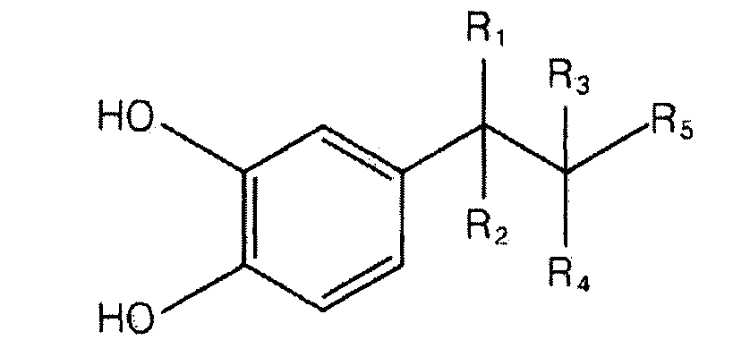
화학식 1
상기 화학식 1에서 R1, R2, R3, R4 및 R5 중 적어도 어느 하나는 각각 티올, 제1 아민 (primary amine), 제 2 아민 (secondary amine), 니트릴 (nitrile), 알데하이드 (aldehyde), 이미다졸 (imidazole), 아자이드 (azide), 할로겐화물 (halide), 폴리헥사메틸렌 디티오카보네이트 (polyhexamethylene dithiocarbonate), 하이드록실 (hydroxyl), 카르복실산 (carboxylic acid), 카르복실에스터 (carboxylic ester) 또는 카르복사미드 (carboxamide)로 구성된 군에서 선택된 1종이며, 나머지 R1, R2, R3, R4 및 R5 는 수소이다.
본 발명은 상기 화학식 1과 같은 코팅제를 간단한 방법으로 분리막에 코팅시킴으로써 소수성인 다공성 분리막의 기공을 손상시키지 않으면서 분리막에 친수성을 부여한다. 또한, 전해액과의 상용성 및 낮은 접촉각 등의 표면 특성 향상을 통해 전해액의 함침능력을 향상시켜 고출력전지와 고용량전지의 생산이 가능한 친수화된 다공성 분리막의 제조방법과 그 리튬 이차전지용 분리막, 그리고 이를 사용한 리튬 이차전지를 제공할 수 있다.
본 발명에 따른 분리막 코팅제는 증류수 기반의 완충용액 및 상기 화학식 1로 표시되는 화합물을 포함하며,다공성 분리막의 기재에 따라 메탄올과 같은 알코올이 선택적으로 첨가될 수 있다. 특히 상기 화학식 1로 표시된 화합물은 도파민계 (dopamine) 물질로서, 상기 도파민계 물질은 약염기 환경(pH 8.5)에서 홍합유래 고분자인 폴리도파민 (polydopamine)으로 자발적인 중합이 이루어지며, 이를 통하여 미다공성 분리막기재의 표면에 얇은 고분자 층을 형성하며, 상기 분리막의 코팅 두께는 0.001 내지 1㎛ 범위일 수 있다.
특히 본 발명에 따라 분리막에 형성되는 폴리도파민은 탁월한 화학적 안정성을 보유하고 있을 뿐만 아니라, 50 nm 내외의 얇은 고분자 코팅 두께로 인하여 미다공성 분리막기재의 기공 손상 없이 효과적으로 소수성의 표면특성을 친수성으로의 전환을 기대할 수 있다. 또한 도파민은 가격이 비싸고 환경에 해로운 일상적인 유기용매를 대신하여, 가격이 저렴하고 친환경적인 증류수 기반의 완충용액(10 mM tris buffer solution, pH 8.5)에 용해되어 사용되었는데, 이는 도파민이 자발적인 중합을 통해 홍합유래 고분자인 폴리도파민 코팅층을 형성하기 위해서는 용액을 약염기(pH 8.5) 상태로 일정하게 유지할 수 있어야 하기 때문이다.
본 발명에 따른 분리막의 다공성 기재는 올레핀계 수지, 불소계 수지, 폴리에스테르계 수지, 셀룰로오스계 수지, 폴리아미드계 수지, 폴리이미드계 수지, 폴리설폰계 수지, 폴리아크릴로니트릴계 수지, 폴리아세탈계 수지, 폴리카보네이트계 수지, 비닐리덴플루오라이드계 수지, 유리섬유 내지 무기물 복합체가 단독 혹은 다층으로 이루어진 형태일 수 있으며, 상기 다공성 기재의 기공 크기는 0.001 내지 1000㎛ 범위, 기공도는 5 내지 95% 범위, 두께는 1 내지 1000㎛ 범위일 수 있다.
이하 실시예 및 도면을 참조하여 본 발명을 더욱 상세히 설명한다. 다음에 소개되는 실시예는 당업자에게 본 발명의 사상이 충분히 전달될 수 있도록 하기 위해 예로서 제공되는 것이다. 따라서 본 발명의 권리범위가 이에 한정되지는 아니한다.
실시예 1
증류수 기반의 완충용액(10 mM tris buffer solution, pH 8.5): 메탄올을 1:1의 비율로 섞고, 하기 화학식 2에 따른 도파민을 용해하였다 (2mg/ml). 30초간의 교반 후, 용액에 다공성 폴리에틸렌 분리막 (Asahi Kasei, 20 ㎛, porosity: 40%)을 함침시켰다. 24시간 이후, 분리막을 꺼내 증류수로 3회 충분히 세척한 이후, 아세톤으로 1회 세척하여 상온의 진공오븐에서 24시간을 건조하였다.
[규칙 제91조에 의한 정정 25.05.2012]
화학식 2 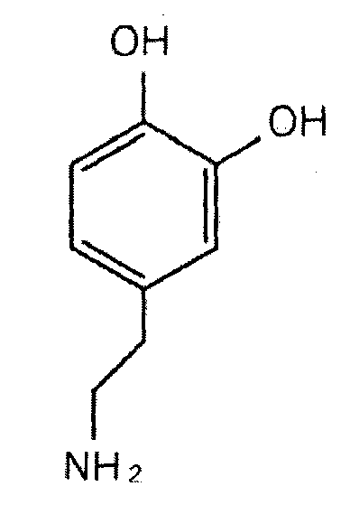
화학식 2
도 1은 본 발명의 친수성 분리막의 제조 절차 모식도이다.
먼저 상기 언급한 도파민을 이용한 분리막 코팅제에 다공성 분리막을 함침 후, 일정 시간 이후 꺼내서 세척하면 표면특성에 친수성이 부여된 다공성 분리막을 얻을 수 있다. 상기 함침 방법은 일반적인 침지코팅법 이외에 가압코팅법, 스핀코팅법, 스프레이법 또는 롤러코팅법 등의 다양한 방식이 사용될 수 있으며, 이는 모두 본 발명의 범위에 속한다.
도 2는 도파민을 이용한 분리막 코팅제에서 발생하는 화학 반응특성을 보여주고 있다. 도 2에서 알 수 있듯이, 도파민을 이용한 분리막 코팅제는 약염기 조건에서 (pH 8.5) 자발적인 중합반응이 일어나 홍합유래의 폴리도파민 고분자를 형성할 수 있다. 따라서, 본 발명에 따른 화학식 1에 따른 화합물이 용해되는 용액의 pH 조건은 7 내지 11인 것이 바람직하며, 화학식 1의 화합물이 자발적으로 중합되는 약염기 조건인 7 내지 9가 보다 바람직하다.
비교예 1
다공성 폴리에틸렌 분리막 (Asahi Kasei, 20 ㎛, porosity: 40%)을 아세톤으로 1회 세척하여 상온의 진공오븐에서 24시간을 건조하였다.
분석결과
생성된 폴리도파민 고분자는 분리막 코팅제에 함침된 분리막 기재 표면에 코팅되는데, 도 3에서 확인할 수 있는 바와 같이 도파민을 이용한 분리막 코팅제에 함침되어 있던 분리막 기재의 표면은 어두운 갈색을 나타내고 있다. 더욱이 폴리도파민 코팅은 매우 얇은 두께로 형성된다고 알려져 있는 바, 미다공성 분리막기재의 기공 손상 없이 효과적으로 코팅이 되었음을 도 4의 비교예 및 실시예를 통해 확인할 수 있었다. 폴리도파민의 코팅 존재를 세밀하게 확인하기 위하여 분리막 표면의 XPS를 측정하였고, 도 5에서 볼 수 있는 바와 같이 실시예에서는 비교예에서 존재하지 않던 새로운 질소 (N1s)와 산소 (O1s)의 피크가 생성되었음을 확인할 수 있었다. 이는 실시예의 분리막 표면에 폴리도파민이 존재에 기인한 것이라 생각된다. 분리막의 단면을 EDX로 관찰한 결과 실시예에서는 폴리도파민에 기인한 새로운 산소 피크가 나타났다. 이를 통해 도파민을 이용한 분리막 코팅제는 다공성 분리막의 표면뿐만 아니라 내부까지 성공적으로 홍합유래 폴리도파민 고분자를 코팅할 수 있음을 알 수 있었다.
또한 도 6 및 7에서 볼 수 있는 바와 같이, 본 발명에 따른 폴리도파민 고분자가 코팅된 다공성 분리막은 기존 다공성 분리막 기재 고유의 기계적 강도(Instron, 인장속도: 1cm/min) 및 열분해 특성(DSC, 가열속도: 10°C/min)을 저해하지 않았음을 확인할 수 있었다. 또한, 본 발명에 따른 폴리도파민 고분자가 코팅된 다공성 분리막은 기존의 소수성 표면 특성의 다공성 분리막에 친수성 표면특성을 효과적으로 제공한다.
도 8에서 알 수 있는 바와 같이, 기존 소수성 표면특성의 다공성 분리막은 108°의 접촉각을 나타내지만, 본 발명에 따른 분리막은 39°로써 접촉각이 크게 감소되었다 (물방울과 분리막 기재와의 접촉각, 0.5㎕). 또한 도 9에서 볼 수 있는 바와 같이, 기존 소수성 표면특성의 다공성 분리막은 전해액(1M LiPF6, EC:DMC:DEC=1:1:1 질량비)과의 상용성이 낮아 12시간 함침 후 표면에 뚜렷하게 액적이 맺혔으나, 본 발명에 따른 폴리도파민 고분자가 코팅된 다공성 분리막은 전해액과의 상용성 증대로 인해 전해액이 분리막 전체에 고르게 퍼져 있음을 확인할 수 있었다. 더 나아가, 전해액과의 상용성은 분리막에 함침되는 전해액 양의 차이를 유발하였고, 그로 인한 이온전도도의 차이를 보였다. 하기 표 1은 폴리도파민 코팅에 따른 분리막의 특성변화를 나타내며, 이를 참조하면, 본 발명에 따른 폴리도파민 고분자가 코팅된 다공성 분리막은 기존 다공성 분리막에 비해 향상된 전해액 함침량과 이온전도도를 나타내는 것을 알 수 있다.
본 발명은 또한, 상기 다공성 분리막이 양극과 음극 사이에 개재되어 있는 전극조립체를 포함하는 것으로 구성된 전기화학 셀을 제공하는 바, 상기 전기화학 셀은 전기화학반응을 통해 전기를 제공하는 것으로서, 예를 들어, 전기화학 이차전지 또는 전기화학 캐패시터일 수 있다.
표 1
| 비교예 | 실시예 | |
| 전해액 함침 양 (%) | 96 | 126 |
| 이온전도도 (mS/cm) | 0.23 | 0.41 |
도 10은 LiMn2O4/분리막/리튬 메탈로 구성되는 리튬 이차전지의 초기 충방전 곡선이다. 다공성 분리막과 본 발명에 따른 폴리도파민 고분자가 코팅된 다공성 분리막의 성능이 크게 차이가 나지 않았음을 확인할 수 있었다. (전해액, 1M LiPF6, EC:DMC:DEC=1:1:1 질량비)
도 11은 상기 이차전지의 출력특성을 보여주는데, 출력특성 분석을 위하여 상기 리튬 이차전지를 1C의 전류 값으로 충전하고, 1C, 3C, 6C, 9C, 12C, 15C, 1C 의 전류 값으로 10 사이클씩 방전하였다.
도 11을 참조하면, 본 발명에 따른 폴리도파민 고분자가 코팅된 다공성 분리막은 기존의 다공성 분리막에 비해 월등히 향상된 출력특성을 보였다. 이는 상기 언급한 바와 같이 전해액과의 상용성 및 젖음성의 향상에 따른 고율구동에서의 전해액 누액 감소에 의한 우수한 이온전도도 유지에 기인한 것으로 생각된다. (전해액, 1M LiPF6, EC:DMC:DEC=1:1:1 질량비) 또한, 본 발명에 따른 폴리도파민 고분자가 코팅된 다공성 분리막은 전해액의 선정에 있어 다양성을 가져올 수 있다. 기존 다공성 분리막의 소수성 표면특성에 의한 상용성 및 젖음성 저하로 전기화학 셀의 구동이 불가능하였던 전해액(1M LiPF6, EC:PC=1:1 질량비)일지라도, 본 발명에 따른 폴리도파민 고분자가 코팅된 다공성 분리막은 충방전 특성을 보일 수 있음을 확인하였다.
열수축 방지제
본 발명은 상술한 방법에 따른 홍합유래 고분자가 분리막의 열수축 방지제로서 작용하는 새로운 효과를 발견하였으며, 이는 하기 실험예를 통하여 설명된다.
비교예
폴리도파민으로 표면처리되지 않은 다공성 폴리에틸렌 분리막 (Asahi Kasei, 20 , porosity: 40%)을 140에서 1시간 고온 보관하였다.
분석결과
도 12는 본 발명에 따른 홍합유래 고분자가 코팅된 분리막인 실시예와 상기 비교예에 따라 고온 환경이 노출된 폴리에틸렌 분리막의 사진이다.
도 12를 참조하면, 우측의 비교예 분리막에 비하여 폴리도파민이 코팅된 실시예의 분리막이 d등이 덜 수축되는 것을 알 수 있다.
표 2 수축률 비교
| 실시예 | 비교예 | |
| 수축률(%) (섭씨 140도, 1시간보존) | 16 | 33 |
상기 표 2의 결과를 참조하면, 홍합유래 고분자인 정도 폴리도파민이 코팅된 폴리올레핀 분리막의 수축률은 코팅되지 않은 분리막의 절반 수준인 것을 알 수 있다. 본 발명은 상술한 바와 같이 홍합유래 고분자를 분리막 표면에 코팅시킴으로써 열 수축 방지 효과를 발생시킨다.
Claims (9)
- 전기화학 소자 분리막으로, 상기 분리막은다공성 기재; 및상기 다공성 기재의 표면 또는 내부에 코팅된 하기 식 1의 화합물을 포함하는 것을 특징으로 하는 분리막.(1)(상기 식에서 R1, R2, R3, R4 및 R5 중 적어도 어느 하나는 각각 티올, 제1 아민 (primary amine), 제 2 아민 (secondary amine), 니트릴 (nitrile), 알데하이드 (aldehyde), 이미다졸 (imidazole), 아자이드 (azide), 할로겐화물 (halide), 폴리헥사메틸렌 디티오카보네이트 (polyhexamethylene dithiocarbonate), 하이드록실 (hydroxyl), 카르복실산 (carboxylic acid), 카르복실에스터 (carboxylic ester) 또는 카르복사미드 (carboxamide)로 구성된 군에서 선택된 1종이며, R1, R2, R3, R4 및 R5 중 이를 제외한 나머지는 수소임)
- [규칙 제91조에 의한 정정 25.05.2012]
리튬이차전지의 폴리올레핀 분리막의 열 수축 방지 방법으로, 상기 방법은 폴리올레핀 분리막에 하기 식 1의 화합물이 중합된 고분자를 코팅시키는 단계를 포함하는 것을 특징으로 하는 리튬이차전지의 폴리올레핀 분리막의 열 수축 방지 방법.(1)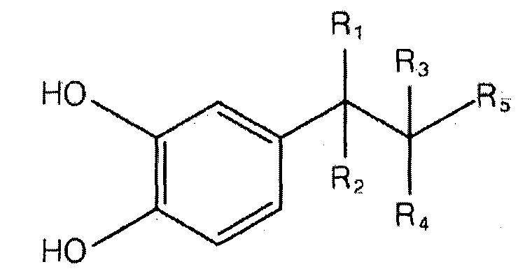 (상기 식에서 R1, R2, R3, R4 및 R5 중 적어도 어느 하나는 각각 티올, 제1 아민 (primary amine), 제 2 아민 (secondary amine), 니트릴 (nitrile), 알데하이드 (aldehyde), 이미다졸 (imidazole), 아자이드 (azide), 할로겐화물 (halide), 폴리헥사메틸렌 디티오카보네이트 (polyhexamethylene dithiocarbonate), 하이드록실 (hydroxyl), 카르복실산 (carboxylic acid), 카르복실에스터 (carboxylic ester) 또는 카르복사미드 (carboxamide)로 구성된 군에서 선택된 1종이며, R1, R2, R3, R4 및 R5 중 이를 제외한 나머지는 수소임)
 - 제 1항 또는 제 2항에 있어서,상기 다공성 기재는 올레핀계 수지, 불소계 수지, 폴리에스테르계 수지, 셀룰로오스계 수지, 폴리아미드계 수지, 폴리이미드계 수지, 폴리설폰계 수지, 폴리아크릴로니트릴계 수지, 폴리아세탈계 수지, 폴리카보네이트계 수지, 비닐리덴플루오라이드계 수지, 유리섬유 내지 무기물 복합체가 단독 혹은 다층으로 이루어진 것을 특징으로 하는 전기화학 소자 분리막.
- 제 3항에 있어서,상기 다공성 기재의 기공 크기는 0.001 내지 1000㎛ 범위, 기공도는 5 내지 95% 범위, 두께는 1 내지 1000um 범위인 것을 특징으로 하는 전기화학 소자 분리막.
- 제 4항에 있어서,상기 분리막의 코팅 두께는 0.001 내지 1㎛ 범위인 것을 특징으로 하는 전기화학 소자 분리막.
- [규칙 제26조에 의한 보정 25.05.2012]
리튬이차전지의 폴리올레핀 분리막의 열 수축 방지 방법으로, 상기 방법은하기 화학식 1의 화합물을 pH 7 내지 11의 용액에 용해시키는 단계; 및(1)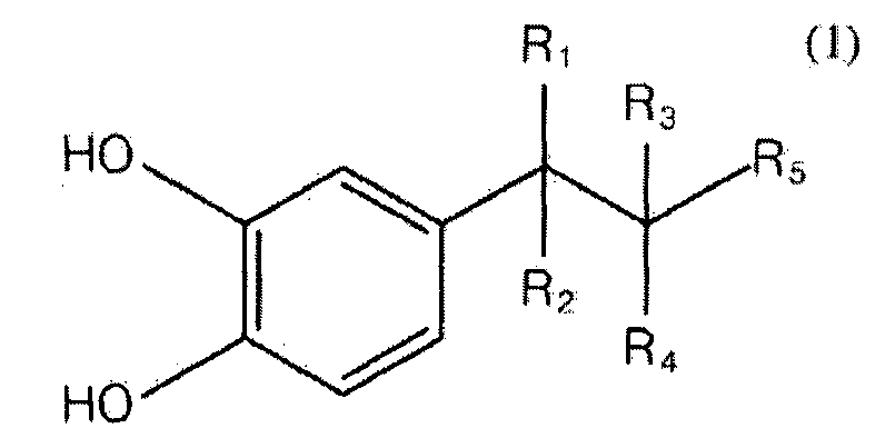 (상기 식에서 R1, R2, R3, R4 및 R5 중 적어도 어느 하나는 각각 티올, 제1 아민 (primary amine), 제 2 아민 (secondary amine), 니트릴 (nitrile), 알데하이드 (aldehyde), 이미다졸 (imidazole), 아자이드 (azide), 할로겐화물 (halide), 폴리헥사메틸렌 디티오카보네이트 (polyhexamethylene dithiocarbonate), 하이드록실 (hydroxyl), 카르복실산 (carboxylic acid), 카르복실에스터 (carboxylic ester) 또는 카르복사미드 (carboxamide)로 구성된 군에서 선택된 1종이며, R1, R2, R3, R4 및 R5 중 이를 제외한 나머지는 수소임)상기 용액에 폴리올레핀 분리막을 침지시키는 단계를 포함하는 것을 특징으로 하는 리튬이차전지의 폴리올레핀 분리막의 열 수축 방지 방법.
 - 제 6항에 있어서,상기 화합물은 상기 용액에서 중합반응을 일으키는 것을 특징으로 하는 리튬이차전지의 폴리올레핀 분리막의 열 수축 방지 방법.
- 제 6항 또는 제 7항에 따른 방법에 의하여 열 수축 방지 방법에 의하여 표면에 코팅층이 형성된 폴리올레핀 분리막.
- 제 8항에 있어서,상기 코팅층은 폴리도파민인 것을 특징으로 하는 폴리올레핀 분리막.
Applications Claiming Priority (4)
| Application Number | Priority Date | Filing Date | Title |
|---|---|---|---|
| KR10-2011-0025603 | 2011-03-23 | ||
| KR20110025603 | 2011-03-23 | ||
| KR1020110054319A KR101198493B1 (ko) | 2011-06-07 | 2011-06-07 | 홍합유래 고분자를 이용한 폴리올레핀 분리막의 열수축 방지방법, 이에 의하여 열 수축 특성이 향상된 폴리올레핀 분리막과 이를 포함하는 리튬이차전지 |
| KR10-2011-0054319 | 2011-06-07 |
Publications (2)
| Publication Number | Publication Date |
|---|---|
| WO2012128460A2 true WO2012128460A2 (ko) | 2012-09-27 |
| WO2012128460A3 WO2012128460A3 (ko) | 2012-11-22 |
Family
ID=46879835
Family Applications (1)
| Application Number | Title | Priority Date | Filing Date |
|---|---|---|---|
| PCT/KR2012/000455 Ceased WO2012128460A2 (ko) | 2011-03-23 | 2012-01-18 | 홍합유래 고분자를 이용한 분리막 코팅제 및 그 제조방법, 열수축 방지제 및 그 제조방법 |
Country Status (1)
| Country | Link |
|---|---|
| WO (1) | WO2012128460A2 (ko) |
Cited By (5)
| Publication number | Priority date | Publication date | Assignee | Title |
|---|---|---|---|---|
| CN104037380A (zh) * | 2014-06-10 | 2014-09-10 | 中国第一汽车股份有限公司 | 一种基于聚多巴胺的改性聚合物颗粒隔膜的制备方法 |
| CN104051691A (zh) * | 2014-06-06 | 2014-09-17 | 中国第一汽车股份有限公司 | 一种基于聚多巴胺的改性复合聚合物隔膜的制备方法 |
| DE102014208145B3 (de) * | 2014-04-30 | 2015-09-03 | Robert Bosch Gmbh | Batteriezelle mit einer beschichteten Elektrode sowie deren Herstellung |
| WO2020179998A1 (ko) * | 2019-03-06 | 2020-09-10 | 삼성에스디아이주식회사 | 세퍼레이터, 이의 제조방법, 및 이를 포함한 이차전지 |
| CN118899621A (zh) * | 2023-11-03 | 2024-11-05 | 中国科学院上海硅酸盐研究所 | 一种热塑性弹性体基改性隔膜、制备方法及钠电池 |
-
2012
- 2012-01-18 WO PCT/KR2012/000455 patent/WO2012128460A2/ko not_active Ceased
Non-Patent Citations (4)
| Title |
|---|
| ADV.FUNT.MATER. vol. 20, 25 May 2010, pages 2132 - 2139 * |
| J.MEM.SCI. vol. 327, 30 November 2008, pages 244 - 253 * |
| J.MEM.SCI. vol. 364, 14 August 2010, pages 194 - 202 * |
| LANGMUIR vol. 25, no. 13, 14 April 2009, pages 7368 - 7374 * |
Cited By (10)
| Publication number | Priority date | Publication date | Assignee | Title |
|---|---|---|---|---|
| DE102014208145B3 (de) * | 2014-04-30 | 2015-09-03 | Robert Bosch Gmbh | Batteriezelle mit einer beschichteten Elektrode sowie deren Herstellung |
| US9692055B2 (en) | 2014-04-30 | 2017-06-27 | Robert Bosch Gmbh | Battery cell having a coated electrode and the production thereof |
| CN104051691A (zh) * | 2014-06-06 | 2014-09-17 | 中国第一汽车股份有限公司 | 一种基于聚多巴胺的改性复合聚合物隔膜的制备方法 |
| CN104037380A (zh) * | 2014-06-10 | 2014-09-10 | 中国第一汽车股份有限公司 | 一种基于聚多巴胺的改性聚合物颗粒隔膜的制备方法 |
| WO2020179998A1 (ko) * | 2019-03-06 | 2020-09-10 | 삼성에스디아이주식회사 | 세퍼레이터, 이의 제조방법, 및 이를 포함한 이차전지 |
| KR20200108144A (ko) * | 2019-03-06 | 2020-09-17 | 삼성에스디아이 주식회사 | 세퍼레이터, 이의 제조방법, 및 이를 포함한 이차전지 |
| KR102317502B1 (ko) * | 2019-03-06 | 2021-10-27 | 삼성에스디아이 주식회사 | 세퍼레이터, 이의 제조방법, 및 이를 포함한 이차전지 |
| US20220190440A1 (en) * | 2019-03-06 | 2022-06-16 | Samsung Sdi Co., Ltd. | Separator, preparation method of same, and secondary battery comprising same |
| US12183947B2 (en) * | 2019-03-06 | 2024-12-31 | Samsung Sdi Co., Ltd. | Separator, including composite coating layer containing inorganic particles and hydrophilic organic compound arranged on web of organic fibers, preparation method of same, and secondary battery comprising same |
| CN118899621A (zh) * | 2023-11-03 | 2024-11-05 | 中国科学院上海硅酸盐研究所 | 一种热塑性弹性体基改性隔膜、制备方法及钠电池 |
Also Published As
| Publication number | Publication date |
|---|---|
| WO2012128460A3 (ko) | 2012-11-22 |
Similar Documents
| Publication | Publication Date | Title |
|---|---|---|
| WO2009096671A2 (en) | Separator for progressing united force to electrode and electrochemical containing the same | |
| CN101471432B (zh) | 一种隔膜及其制备方法及锂离子电池 | |
| KR100656085B1 (ko) | 전해액 가용성 고분자가 코팅된 분리막, 이를 포함하는 전기 화학 소자 및 상기 전기 화학 소자의 제조방법 | |
| WO2010076989A2 (ko) | 다공성 코팅층을 구비한 세퍼레이터 및 이를 구비한 전기화학소자 | |
| WO2011105866A2 (ko) | 세퍼레이터의 제조방법, 이로부터 형성된 세퍼레이터 및 이를 포함하는 전기화학소자의 제조방법 | |
| WO2010117195A2 (ko) | 다공성 코팅층을 포함하는 세퍼레이터, 그 제조방법 및 이를 구비한 전기화학소자 | |
| WO2011040704A2 (ko) | 세퍼레이터의 제조방법, 이로부터 형성된 세퍼레이터 및 이를 포함하는 전기화학소자의 제조방법 | |
| WO2009110726A2 (en) | Separator having porous coating layer and electrochemical device containing the same | |
| WO2019216713A1 (ko) | 안전성이 향상된 리튬 금속 이차전지 및 그를 포함하는 전지모듈 | |
| WO2010027203A2 (ko) | 다공성 코팅층을 구비한 세퍼레이터 및 이를 구비한 전기화학소자 | |
| WO2012128440A1 (ko) | 전극조립체 및 이의 제조방법 | |
| WO2010024559A2 (ko) | 다공성 코팅층을 구비한 세퍼레이터, 그 제조방법 및 이를 구비한 전기화학소자 | |
| WO2016148408A1 (ko) | 일체형 전극조립체 및 이를 포함하는 전기화학소자 | |
| WO2016093589A1 (ko) | 안전성이 향상된 전극조립체, 그의 제조방법 및 상기 전극조립체를 포함하는 전기화학소자 | |
| WO2013165151A1 (ko) | 세퍼레이터 및 이를 구비한 전기화학소자 | |
| WO2011105865A2 (ko) | 세퍼레이터의 제조방법, 이로부터 형성된 세퍼레이터 및 이를 포함하는 전기화학소자의 제조방법 | |
| WO2013058421A1 (ko) | 세퍼레이터의 제조방법, 이로부터 형성된 세퍼레이터 및 이를 구비한 전기화학소자 | |
| WO2017010780A1 (ko) | 세퍼레이터 및 이를 포함하는 전기화학소자 | |
| KR101334888B1 (ko) | 리튬 이차전지용 분리막 및 그 제조방법 | |
| WO2012046966A2 (ko) | 사이클 특성이 개선된 전기화학소자 | |
| WO2014073937A1 (ko) | 세퍼레이터의 제조방법, 그에 의해 제조된 세퍼레이터 및 그를 포함하는 전기화학소자 | |
| WO2011019187A2 (ko) | 리튬 이차전지 | |
| WO2014084681A1 (ko) | 표면 특성이 다른 무기물 입자의 이중 다공성 코팅층을 포함하는 이차전지용 분리막, 이를 포함하는 이차전지, 및 상기 분리막의 제조방법 | |
| US20210175483A1 (en) | Ceramic separator and method for manufacturing thereof | |
| WO2012102548A2 (ko) | 원통형 이차전지 |
Legal Events
| Date | Code | Title | Description |
|---|---|---|---|
| 121 | Ep: the epo has been informed by wipo that ep was designated in this application |
Ref document number: 12760835 Country of ref document: EP Kind code of ref document: A2 |
|
| NENP | Non-entry into the national phase |
Ref country code: DE |
|
| 122 | Ep: pct application non-entry in european phase |
Ref document number: 12760835 Country of ref document: EP Kind code of ref document: A2 |