WO2012128314A1 - 視差算出装置、距離算出装置及び視差算出方法 - Google Patents
視差算出装置、距離算出装置及び視差算出方法 Download PDFInfo
- Publication number
- WO2012128314A1 WO2012128314A1 PCT/JP2012/057320 JP2012057320W WO2012128314A1 WO 2012128314 A1 WO2012128314 A1 WO 2012128314A1 JP 2012057320 W JP2012057320 W JP 2012057320W WO 2012128314 A1 WO2012128314 A1 WO 2012128314A1
- Authority
- WO
- WIPO (PCT)
- Prior art keywords
- image
- correction amount
- unit
- parallax
- reference image
- Prior art date
- Legal status (The legal status is an assumption and is not a legal conclusion. Google has not performed a legal analysis and makes no representation as to the accuracy of the status listed.)
- Ceased
Links
Images












Classifications
-
- H—ELECTRICITY
- H04—ELECTRIC COMMUNICATION TECHNIQUE
- H04N—PICTORIAL COMMUNICATION, e.g. TELEVISION
- H04N13/00—Stereoscopic video systems; Multi-view video systems; Details thereof
- H04N13/10—Processing, recording or transmission of stereoscopic or multi-view image signals
- H04N13/106—Processing image signals
- H04N13/128—Adjusting depth or disparity
-
- G—PHYSICS
- G01—MEASURING; TESTING
- G01C—MEASURING DISTANCES, LEVELS OR BEARINGS; SURVEYING; NAVIGATION; GYROSCOPIC INSTRUMENTS; PHOTOGRAMMETRY OR VIDEOGRAMMETRY
- G01C3/00—Measuring distances in line of sight; Optical rangefinders
- G01C3/02—Details
- G01C3/06—Use of electric means to obtain final indication
- G01C3/08—Use of electric radiation detectors
- G01C3/085—Use of electric radiation detectors with electronic parallax measurement
-
- G—PHYSICS
- G01—MEASURING; TESTING
- G01S—RADIO DIRECTION-FINDING; RADIO NAVIGATION; DETERMINING DISTANCE OR VELOCITY BY USE OF RADIO WAVES; LOCATING OR PRESENCE-DETECTING BY USE OF THE REFLECTION OR RERADIATION OF RADIO WAVES; ANALOGOUS ARRANGEMENTS USING OTHER WAVES
- G01S11/00—Systems for determining distance or velocity not using reflection or reradiation
- G01S11/12—Systems for determining distance or velocity not using reflection or reradiation using electromagnetic waves other than radio waves
-
- G—PHYSICS
- G06—COMPUTING OR CALCULATING; COUNTING
- G06T—IMAGE DATA PROCESSING OR GENERATION, IN GENERAL
- G06T7/00—Image analysis
- G06T7/50—Depth or shape recovery
- G06T7/55—Depth or shape recovery from multiple images
- G06T7/593—Depth or shape recovery from multiple images from stereo images
-
- G—PHYSICS
- G06—COMPUTING OR CALCULATING; COUNTING
- G06T—IMAGE DATA PROCESSING OR GENERATION, IN GENERAL
- G06T2207/00—Indexing scheme for image analysis or image enhancement
- G06T2207/10—Image acquisition modality
- G06T2207/10004—Still image; Photographic image
- G06T2207/10012—Stereo images
-
- G—PHYSICS
- G06—COMPUTING OR CALCULATING; COUNTING
- G06T—IMAGE DATA PROCESSING OR GENERATION, IN GENERAL
- G06T2207/00—Indexing scheme for image analysis or image enhancement
- G06T2207/10—Image acquisition modality
- G06T2207/10024—Color image
-
- G—PHYSICS
- G06—COMPUTING OR CALCULATING; COUNTING
- G06T—IMAGE DATA PROCESSING OR GENERATION, IN GENERAL
- G06T2207/00—Indexing scheme for image analysis or image enhancement
- G06T2207/20—Special algorithmic details
- G06T2207/20021—Dividing image into blocks, subimages or windows
Definitions
- the present invention relates to a parallax calculation device that photographs a subject with a plurality of cameras and calculates parallax from each camera image, a distance calculation device that calculates a distance between the camera and the subject, and a parallax calculation method.
- An imaging system that generates a stereoscopic image or a free viewpoint image based on a plurality of images obtained by imaging the same subject from a plurality of viewpoints with a camera is known.
- distance information depth information
- this imaging system distance information (depth information) of a subject is calculated from the parallax, which is a relative shift amount between images, using the principle of triangulation, and an image viewed from an arbitrary virtual viewpoint based on the distance information. Is generated.
- corresponding points between the two images are detected.
- an SAD method using a sum of absolute differences SAD: SumSOf Absolute Difference
- an SSD method using a sum of squares of differences SSD: Sum of Squared Difference
- SAD SumSOf Absolute Difference
- SSD Sum of Squared Difference
- the epipolar line is a straight line in which an epipolar plane which is a plane including two viewpoints and a target point in space or on an object intersects each image.
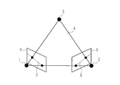
- FIG. 23 is a schematic diagram showing an epipolar plane and epipolar lines.
- the epipolar lines 7 and 8 are triangles composed of three points of the object point 3 and two viewpoints (centers of the lenses of the first camera 1 and the second camera 2) in the space and three line segments connecting them.
- the plane 4 (epipolar plane) 4 the image plane 5 photographed by the first camera 1, and the image plane 6 photographed by the second camera 2. Since the corresponding point in the other image corresponding to the attention point in one image exists on the epipolar line, the corresponding point can be detected by searching on the epipolar line.
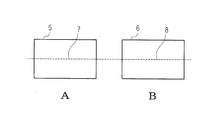
- 24A and 24B are schematic diagrams illustrating a case where the first camera 1 and the second camera 2 are arranged so that the optical axes of the first camera 1 and the second camera 2 are parallel to each other.
- the epipolar lines 7 and 8 are horizontal straight lines having the same height in both image planes, the corresponding points may be searched for on the same line in both images.
- image displacement may occur between the two images due to the mounting accuracy of the two cameras or lens distortion, and the epipolar line in each camera is not necessarily the same line in the two images.
- the corresponding points cannot be found, and an area where accurate parallax cannot be calculated increases.
- it is necessary to correct the image shift.
- a simple method of moving and adjusting the entire screen has low correction accuracy, and is caused by camera mounting accuracy or lens distortion. The corrected image shift cannot be corrected sufficiently.
- Patent Document 1 describes an apparatus that corrects a rotational deviation or translational deviation of an image in real time using affine transformation that is geometric coordinate transformation.
- Patent Document 2 the second pattern having the highest correlation with the first pattern in one image is detected from a plurality of horizontal and vertical lines in the other image, and the first and second patterns are detected.
- An apparatus for calculating parallax from the first and second position information is described. According to this apparatus, since the corresponding points are searched on the horizontal line and the vertical line in the image, it is possible to prevent erroneous distance measurement due to image shift without correcting the entire image.
- JP 2001-82955 A Japanese Patent Laid-Open No. 2003-4442
- the present invention has been made in view of such circumstances, and a parallax calculation device that easily calculates an accurate parallax by dividing an image into a plurality of regions and correcting an image shift for each region, and its accurate It is an object of the present invention to provide a distance calculation device and a parallax calculation method for calculating a distance between a camera and a subject based on various parallaxes.
- the parallax calculation device of the present invention is a parallax calculation device that calculates parallax as an image shift between images obtained from two viewpoints, an image dividing unit that divides each of the images into a plurality of regions, and the image dividing unit A correction amount determination unit that calculates an image shift amount between the images in a direction perpendicular to a direction connecting two viewpoints for each of the divided areas, and determines a correction amount corresponding to the image shift amount; and the correction amount determination A parallax calculating unit that corrects an image for each of the regions based on a correction amount determined by the unit and calculates a parallax based on the corrected image.
- an image is divided into a plurality of regions, and correction of image deviation in the vertical direction is performed for each region, so that accurate parallax can be easily calculated.
- the parallax calculation device of the present invention further includes a correction instruction unit that instructs the correction amount determination unit to determine the correction amount, and the correction amount determination unit determines the correction amount in accordance with an instruction from the correction instruction unit. It is characterized by being.
- the correction instruction unit instructs the correction amount determination unit to determine a correction amount every time a predetermined number of frames are acquired. It is made to do so.
- the correction instruction unit detects switching of a video scene, and when the switching of the video scene is detected, instructs the correction amount determination unit to determine a correction amount. It is characterized by being.
- the correction amount can be determined at the time of switching between video scenes in which the image shift amount changes.
- the correction instruction unit detects an acceleration, and when detecting an acceleration equal to or greater than a predetermined threshold, instructs the correction amount determination unit to determine a correction amount. It is characterized by that.
- the parallax calculation device of the present invention further includes a storage unit that stores the correction amount of each region, and the correction amount determination unit determines the correction amount based on a past correction amount stored in the storage unit. It is characterized by being.
- the process of determining the correction amount can be reduced.
- the parallax calculation unit selects a minimum value from the image shift amounts calculated for each region, and the minimum value According to the present invention, the entire image is corrected and then the image is corrected for each region.
- the image shift amount for each region is reduced by performing correction for all regions based on the minimum image shift amount.
- the corresponding point search range for calculation can be narrowed, and the amount of calculation for that can be reduced.
- the parallax calculation device is characterized in that the image dividing unit divides the region so as to have different sizes.
- the amount of image shift differs greatly depending on the location in the image, and a region having a different size is set depending on the location in the image, fine correction is made according to the amount of image shift. It can be performed.
- the parallax calculation device is characterized in that the image dividing unit divides the image so that a central area of the image is large and a peripheral area of the image is small.
- the present invention since the area is reduced in the peripheral portion of the image where the image shift amount increases due to lens distortion, fine correction can be performed, and highly accurate parallax can be obtained.
- the parallax calculation device of the present invention includes a difference calculation unit that calculates a correction amount difference between adjacent regions based on the correction amount of each region determined by the correction amount determination unit, and the image dividing unit includes: When the difference between the areas calculated by the difference calculation unit is greater than or equal to a predetermined threshold, each of the areas is further divided.
- the image division unit determines the number of divisions for dividing each of the adjacent regions according to the difference calculated by the difference calculation unit, and further divides the determined number of divisions. It is characterized by being.
- the distance calculation apparatus includes the parallax calculation apparatus and a distance calculation unit that calculates a distance between the viewpoint and the subject based on the parallax calculated by the parallax calculation apparatus.
- an accurate subject distance can be easily calculated.
- the parallax calculation method of the present invention includes an image dividing step for dividing each image obtained from two viewpoints into a plurality of regions, and a direction perpendicular to the direction connecting the two viewpoints for each of the regions divided by the image dividing step.
- a correction amount determining step for calculating an image shift amount between the images in step S1 and determining a correction amount corresponding to the image shift amount, and correcting the image for each region based on the correction amount determined by the correction amount determination step.
- an accurate parallax can be easily calculated by dividing an image into a plurality of regions and correcting the image for each region. Further, according to the present invention, the distance between the camera and the subject can be calculated based on the accurate parallax.
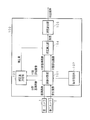
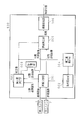
- FIG. 3 is a block diagram illustrating a configuration example of a disparity calculating apparatus according to Embodiment 1.
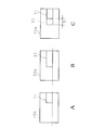
- FIG. It is explanatory drawing which shows a division
- FIG. 3 is an explanatory diagram schematically showing a region in the division standard image and the division reference image shown in FIG. 2 and a part of a subject image included in the region. It is explanatory drawing which shows a block matching typically. It is explanatory drawing which shows a division
- FIG. 6 is an explanatory diagram schematically illustrating a region in the division standard image and the division reference image illustrated in FIG. 5 and a part of a subject image included in the region.
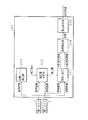
- FIG. 10 is a block diagram illustrating a configuration example of a disparity calculating apparatus according to Embodiment 4.
- FIG. 10 is a block diagram illustrating a configuration example of a disparity calculating apparatus according to Embodiment 5. It is explanatory drawing which shows a reference
- FIG. 1 is a block diagram illustrating a configuration example of the parallax calculation apparatus according to the first embodiment.
- the first camera 1 and the second camera 2 capture the same subject at the same timing, and provide the captured pair of left and right reference images and reference images to the parallax calculation device 100.
- the image of the first camera located on the left side with respect to the subject is referred to as a reference image
- the image of the second camera located on the right side with respect to the subject is referred to as a reference image.
- the first camera and the second camera are arranged by a parallel method.
- the parallel method is a method in which the cameras are arranged at the same height so that the directions of the two cameras, that is, their optical axes are substantially parallel.
- the parallax calculation apparatus 100 inputs a standard image and a reference image captured by the first camera 1 and the second camera 2, and executes a corresponding point search process and a parallax calculation process using the standard image and the reference image.
- the parallax calculation device 100 includes an image division unit 101, a condition setting unit 102, a correction amount determination unit 103, a parallax calculation unit 104, and a parallax integration unit 105.
- the image dividing unit 101 divides the standard image and the reference image into a plurality of regions in accordance with the number of divisions set by the condition setting unit 102, the divided standard image (hereinafter referred to as a divided standard image), and the divided reference image (Hereinafter referred to as a divided reference image) is stored in a predetermined area of an image memory (not shown).
- the image division unit 101 provides the division standard image and the division reference image to the correction amount determination unit 103 and the parallax calculation unit 104.
- the condition setting unit 102 sets the number of image divisions.
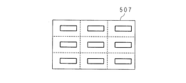
- the number of divisions is, for example, 9 (length 3 ⁇ width 3), 16 (length 4 ⁇ width 4), 25 (length 5 ⁇ width 5), and the like. That is, the image dividing unit 101 divides each of the standard image and the reference image into 9 regions, 16 regions, 25 regions, or the like.
- the correction amount determination unit 103 acquires the division standard image and the division reference image from the image division unit 101.
- the correction amount determination unit 103 determines the division standard image and the division reference image.
- An image shift amount between reference images is calculated, and a correction amount for reducing the image shift is determined for each region.
- the correction amount determination unit 103 gives the correction amount for each region to the parallax calculation unit 104.
- the image shift in the vertical direction means, for example, a shift between two captured images existing in the vertical direction with respect to the direction in which the two cameras are separated. In the case where a person views an image, this is an image shift between images in a direction perpendicular to a direction connecting two viewpoints.
- the parallax calculation unit 104 receives the correction amount for each region from the correction amount determination unit 103, and reads the division reference image and the division reference image from the image memory according to the correction amount. Specifically, the parallax calculation unit 104 reads the image from the storage area in which the image of each area of the division reference image is stored, and the divided reference image from the storage area in which the image of each area of the divided reference image is stored. And the parallax is calculated by changing the line where the corresponding point search is performed according to the correction amount.
- the parallax calculation unit 104 corrects the divided reference image according to the correction amount received from the correction amount determination unit 103, performs a corresponding point search using the divided reference image and the corrected divided reference image, and calculates the parallax for each region. To do.
- the parallax calculation unit 104 gives the calculated parallax for each region to the parallax integration unit 105.
- the parallax means a difference in the positions of the images seen by the right eye and the left eye, and is a relative image shift amount between the images.
- the parallax integration unit 105 integrates the parallax for each area received from the parallax calculation unit 104 and obtains the parallax according to the image size before the division. This is the integrated parallax.
- FIG. 2 is an explanatory diagram schematically showing a division standard image and a division reference image.
- FIG. 2A shows a divided reference image
- FIG. 2B shows a divided reference image.
- the image dividing unit 101 divides each of the standard image and the reference image into, for example, nine regions.
- the division standard image 10 and the division reference image 20 include a subject image 11 and a subject image 21 that indicate the same subject.
- the background portion other than the subject image is a uniform color background.
- the subject images 11 and 21 are assumed to be composed of three horizontally long rectangles. Since the lens positions (viewpoints) of the first camera 1 and the second camera 2 are different, the subject image 21 in the divided reference image 20 photographed by the second camera located to the right of the subject is to the left of the subject. It exists in the position which shifted
- a part of the subject image 21 in the area 20 a of the divided reference image 20 is in the area 10 a of the divided reference image 10. It exists at a position shifted by a width D in the left direction with respect to a part of the subject image 11.
- the width D is a parallax between the division standard image and the division reference image, and is represented by the number of pixels.
- the parallax is a D pixel. Since the first camera 1 and the second camera 2 are arranged in parallel with no congestion, the parallax is 0 at infinity, and the subject closer to the camera has a larger parallax.
- Convergence is a type of eye movement, which is the movement of both eyes that attempts to cross the line of sight with a target, and means that the optical axes of the cameras intersect in the camera.
- FIG. 3 is an explanatory diagram schematically showing one region in the division standard image and the division reference image shown in FIG. 2 and a part of the subject image included therein.
- 3A is a region in the divided reference image and a part of the subject image included in the divided reference image
- FIG. 3B is a region in the divided reference image and a part of the subject image included in the divided reference image
- FIG. A state in which one area shown and a part of the subject image are superimposed is schematically shown.
- a region 10 a in the divided reference image 10 includes a part of the subject image 11
- a region 20 a in the divided reference image 20 includes a part of the subject image 21.
- the region 15a virtually represents a state where the region 10a and the region 20a are overlapped.
- the region 10a and the region 20a have a parallax D.
- a method for obtaining the parallax D will be described.
- a part of the subject image 11 included in the region 10a in the divided reference image 10 and a part of the subject image 21 included in the region 20a in the divided reference image 20 are horizontal in which the vertical coordinates in both images are the same. It is located on a line (hereinafter referred to as “same line”). Therefore, the parallax calculation unit 104 sets a point of interest (arbitrary point) in a part of the subject image 11 included in the region 10 a in the division reference image 10 and corresponds to the point of interest in a part of the subject image 21. Search for a point. Specifically, the parallax calculation unit 104 performs block matching using a pixel block of a predetermined size for a part of the subject image 11 and a part of the subject image 21. The parallax calculation unit 104 performs block matching on the same line, obtains the degree of correlation between corresponding pixel blocks, and detects corresponding points.
- the parallax calculation unit 104 detects a corresponding point corresponding to the attention point based on the degree of correlation, and obtains the distance between the attention point and the corresponding point, that is, the parallax.
- the parallax calculation unit 104 detects the corresponding points by performing block matching in the other areas in the divided reference image 10 and the divided reference image 20 in the same manner, and obtains the parallax for each area from the attention point and the corresponding points.
- FIG. 4 is an explanatory diagram schematically showing block matching.
- the parallax calculation unit 104 sets the standard image window 10 w in the area 10 a in the divided standard image 10 and sets the reference image window 20 w in the area 20 a in the divided reference image 20.
- the standard image window 10w and the reference image window 20w are located on the same line (dotted line).
- each of the standard image window 10w and the reference image window 20w extracts a pixel block composed of 3 ⁇ 3 pixels from the images included in the region 10a and the region 20a.
- the point of interest exists at the barycentric position (center position) of the pixel block extracted by the reference image window 10w.
- the parallax calculation unit 104 obtains a pixel value of a pixel included in the pixel block from the pixel block extracted using the reference image window 10w. Similarly, the parallax calculation unit 104 obtains a pixel value of a pixel included in the pixel block from the pixel block extracted using the reference image window 20w.
- the parallax calculation unit 104 extracts a pixel block of the same size (3 ⁇ 3 pixels) from each of the area 10a and the area 20a while moving the standard image window 10w and the reference image window 20w in the horizontal direction, and extracts the extracted pixel blocks.
- Block matching is performed for the pixel blocks, and the degree of correlation between the two pixel blocks is obtained.
- the degree of correlation can be obtained, for example, by calculating a correlation value by the SAD method. In the SAD method, the degree of correlation is represented by an SAD value.
- the SAD value is a difference absolute value of pixel values of corresponding pixels in the two pixel blocks extracted by the standard image window 10w and the reference image window 20w for each corresponding pixel, and the difference absolute value is calculated for all the values in both windows. It is the value added over the pixels.
- the SAD value is Obtained from the equation.
- the smaller the SAD value the higher the correlation between the two pixel blocks, and the higher the SAD value, the lower the correlation. That is, the correlation degree of the pixel block extracted by each of the standard image window 10w and the reference image window 20w is determined based on the magnitude of the SAD value.
- the SAD value is calculated using the pixel values of the monochrome image.
- RGB information may be converted into luminance information or the like, and the SAD value may be calculated using the converted information.
- the parallax calculation unit 104 sets the reference image window 10w at a position away from the right end of the region 10a by a distance W, and fixes the reference image window 10w at that position.
- the parallax calculation unit 104 sets the reference image window 20w at a position away from the right end of the region 20a by a distance (W + S).
- the parallax calculation unit 104 uses the width S as a search range, and performs block matching between the pixel blocks in the standard image window 10w and the reference image window 20w while moving the reference image window 20w by the number of pixels in the search range.
- the parallax increases as the camera baseline length increases.
- the parallax increases as the depth distance of the subject decreases, and approaches 0 as it approaches infinity. Therefore, it is preferable to set the search range according to the camera base line length or the depth distance from the camera to the subject, and the value becomes larger as the base line length becomes longer or the depth distance becomes longer.
- the maximum value of the search range is set in advance, and when the depth distance of the subject is 1 meter or less, the search range is the maximum value, and when the depth distance is 1 meter or more, the search range is about half of the maximum value. There are methods such as setting.
- the parallax calculation unit 104 fixes the reference image window 10w at a position away from the right end of the region 10a by a distance W, and moves the reference image window 20w from a position away from the right end of the region 20a by a distance (W + S) from the right end. Block matching is performed while moving one pixel at a time to the position separated by W to the right.
- the parallax calculation unit 104 identifies the pixel block extracted by the reference image window 10w fixed in the region 10a and the smallest SAD value (minimum SAD value), that is, the pixel block having the highest degree of correlation in the region 20a. To do.
- the corresponding point corresponding to the point of interest located at the center of the pixel block extracted by the reference image window 10w is located at the center of the identified pixel block. In this way, the parallax calculation unit 104 detects corresponding points.
- the parallax calculation unit 104 calculates the parallax from the distance between the attention point and the corresponding point for each region, and calculates the parallax in all the pixels of the reference image 10.
- the standard image window 10w and the reference image window 20w have a size corresponding to a 3 ⁇ 3 pixel block, but each window has a size of 5 ⁇ 5 pixels or 9 ⁇ 9 pixels.
- Various window sizes such as a size corresponding to a pixel block or a size corresponding to a pixel block having an even number of vertical and horizontal pixels such as 4 ⁇ 4 pixels may be used.
- the reference image window 20w is moved in the right direction, but may be moved in the left direction. That is, block matching may be performed while moving the reference image window 20w pixel by pixel leftward from a position away from the right end of the region 20a to a position away from the right end by a distance (W + S).
- the method for searching for corresponding points when there is no vertical image shift between the divided reference image and the divided reference image has been described above. As described above, when there is no image shift, a corresponding point search may be simply performed on the same line between both images.
- Vertical image misalignment means that if there is distortion in the lens, the camera mounting accuracy is low, if the camera itself is tilted where it should be placed without misalignment in parallel, or if the camera is misaligned in the vertical direction. Occurs when placed.
- the parallax calculation unit 104 performs corresponding point search after correcting the image shift in the vertical direction, and calculates the parallax.
- a process for correcting the image shift in the vertical direction will be described in detail.
- the correction amount determination unit 103 calculates the image shift amount in the vertical direction between the divided reference image and the divided reference image for each region, and determines the correction amount of the divided reference image based on the image shift amount for each region.
- the parallax calculation unit 104 receives the correction amount from the correction amount determination unit 103, corrects the divided reference image based on the correction amount, and performs corresponding point search using the divided reference image and the corrected divided reference image.
- FIG. 5 is an explanatory diagram schematically showing a division standard image and a division reference image.
- FIG. 5A shows a divided reference image
- FIG. 5B shows a divided reference image.
- the image dividing unit 101 divides each of the standard image and the reference image into, for example, nine regions.
- Each of the division standard image 30 and the division reference image 40 includes a subject image 31 and a subject image 41.
- the subject images 31 and 41 are composed of, for example, three horizontally long rectangles. Since the lens positions (viewpoints) of the first camera 1 and the second camera 2 are different, and there is a difference in the mounting accuracy or lens accuracy of each camera, the subject image 41 in the divided reference image 40 is a divided reference image. It exists at a position shifted leftward and downward with respect to the subject image 31 within 30. That is, there is an image shift in the vertical direction between the divided standard image 30 and the reference image 40.
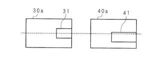
- FIG. 6 is an explanatory diagram schematically showing a region in the division standard image and the division reference image shown in FIG. 5 and a part of the subject image included therein.
- 6A is a region in the divided reference image and a part of the subject image included therein
- FIG. 6B is a region in the divided reference image and a part of the subject image included in the divided reference image
- FIG. 6C is a diagram of FIGS. 6A and 6B, respectively.
- a state in which the region indicated by and the subject image are superimposed is schematically shown.
- the region 30 a includes a part of the subject image 31, and the region 40 a includes a part of the subject image 41.
- the subject image 41 in the region 40a is shifted in the number of E pixels in the left direction and the number of F pixels in the downward direction with respect to the subject image 31 in the region 30a.
- the shift in the left direction is parallax
- the shift in the downward direction is an image shift in the vertical direction due to a difference in the accuracy of attaching each camera or the accuracy of the lens.
- the above-described horizontal block matching is performed in a state where partial vertical image displacement occurs in this way, the corresponding point may not be detected and correct parallax may not be calculated.
- the parallax corresponding to the point of interest located in the portion is as described above. There is a possibility that it can be detected correctly by horizontal block matching. However, since the corresponding point corresponding to the point of interest located in the upper left corner of the subject image 31 does not exist on the same line, there is a high possibility of being erroneously detected. Therefore, the accuracy of the parallax obtained from the entire image of the division standard image 30 and the division reference image 40 is not high.
- FIG. 7 is an explanatory diagram schematically showing a region in the divided reference image and the divided reference image and a part of the subject image included in the region.
- FIG. 7A shows one area in the divided reference image and a part of the subject image included therein
- FIG. 7B shows one area in the divided reference image and a part of the subject image included therein.
- a region 50 a is a region in the division reference image 30, and a region 60 a is a region in the divided reference image 40.
- the region 50 a includes a part of the subject image 51, and the region 60 a includes a part of the subject image 61.
- the subject image 61 in the region 60a is greatly displaced in the vertical direction with respect to the subject image 51 in the region 50a.
- the above-described horizontal block matching is performed in a state where a complete vertical image shift occurs between the divided reference image 30 and the divided reference image 40, the possibility of erroneous detection of corresponding points is very high. For this reason, it is more difficult to calculate an accurate parallax than when there is a partial vertical image shift between the divided reference image 30 and the divided reference image 40.
- the correction amount determination unit 103 calculates the vertical image shift amount between the divided reference image 30 and the divided reference image 40 for each region based on the horizontal center line of each region in the divided reference image 30.
- the correction amount is determined based on the image shift amount for each region, and is given to the parallax calculation unit 104.
- the parallax calculation unit 104 corrects the divided reference image 40 based on the correction amount received from the correction amount determination unit 103, and performs corresponding point search using the corrected divided reference image. The process will be specifically described below.
- FIG. 8A and 8B are explanatory diagrams for explaining correction of image shift in the vertical direction.
- FIG. 8A shows one area in the divided reference image and the divided reference image
- FIG. 8B shows one area in the divided reference image and the corrected divided reference image.
- a region 30 a in the divided reference image 30 includes a part of the subject image 31
- a region 40 a in the divided reference image 40 includes a part of the subject image 41.
- the correction amount determination unit 103 sets a reference image window for extracting an image block of 3 ⁇ 3 pixels on the center line (dotted line) of the region 30 a in the divided reference image 30, and the region in the divided reference image 40
- a reference image window for extracting a pixel block of 3 ⁇ 3 pixels is set on the center line of 40a.
- the correction amount determination unit 103 fixes the position of the standard image window, performs block matching while moving the position of the reference image window one pixel at a time along the center line, and obtains the SAD value at each position. If the search range until a corresponding point corresponding to a certain point of interest is detected is, for example, 10 pixels long, the correction amount determination unit 103 obtains 10 SAD values, and from among these SAD values, Select the minimum SAD value.
- the correction amount determination unit 103 moves and fixes the reference image window by one pixel in the horizontal direction, and again performs block matching while moving the reference image window by one pixel in the horizontal direction to calculate the minimum SAD value. Repeat.
- the correction amount determination unit 103 obtains the SAD value for the search range in each pixel of the reference image, and calculates the minimum SAD value from the SAD value. That is, the correction amount determination unit 103 obtains the minimum SAD value equal to the number of pixels that is the amount of movement of the reference image window. The correction amount determination unit 103 adds all the obtained minimum SAD values and obtains the sum of the minimum SAD values. The sum of the minimum SAD values is a value obtained by block matching in the state shown in FIG. 8A.
- the correction amount determination unit 103 moves the region 40a in the divided reference image 40 upward by one pixel, performs the same processing as described above, and obtains the sum of the minimum SAD values.
- the movement is different from the corresponding point search in the same line described in the basic corresponding point search method, and the center line of the reference image window for performing the corresponding point search is perpendicular to the center line of the reference image window.
- This is a simple process.
- the correction amount determination unit 103 moves the region 40a in the divided reference image 40 by 5 pixels in the vertical direction.
- the correction amount determination unit 103 obtains the sum of the minimum SAD values every time the number of pixels is moved. As a result, the correction amount determination unit 103 obtains F total sums of the minimum SAD values. The correction amount determination unit 103 selects the smallest sum of the minimum SAD values from the sum of the minimum SAD values. The amount of movement of the region 40a when the sum of the smallest minimum SAD values is obtained corresponds to the amount of image shift in the vertical direction.
- the correction amount determination unit 103 obtains the sum of the minimum SAD values each time the divided reference image 40 is moved pixel by pixel within the range of ⁇ 5 pixels to +5 pixels in the vertical direction, and the sum of the minimum SAD values is minimized.
- the case is specified, and the movement amount of the region 40a in that case is set as the image shift amount.
- the image shift amount F shown in FIG. 8B is 2 pixels, and the correction amount is determined to be +2.
- the sign of the correction amount when moving the area 40a upward is +, and the sign of the correction amount when moving downward is-.
- the correction amount determination unit 103 determines the correction amount by obtaining the image shift amount between the divided reference image and the divided reference image for each region, and sends the correction amount to the parallax calculation unit 104.
- the parallax calculation unit 104 performs corresponding point search after moving the divided reference image according to the correction amount. As a result, the possibility that corresponding points of each image exist on the same line increases, so that it is possible to calculate an accurate parallax before correction.
- the parallax calculation unit 104 gives the parallax calculated for each region to the parallax integration unit 105.
- the parallax integration unit 105 integrates the parallax for each region received from the parallax calculation unit 104 and obtains an integrated parallax that matches the image size before the division. That is, in the parallax integration unit 105, the parallax for each region is integrated as parallax data (parallax map) corresponding to each pixel of the reference image.
- the correction amount determination unit 103 may select the minimum image shift amount from the image shift amounts obtained for each region, and determine the correction amount according to the minimum image shift amount.
- the parallax calculation unit 104 responds after correcting the image of all the regions in the divided reference image by the amount of the minimum image shift, and then correcting according to the correction amount of each region for the image after the movement. A point search is performed to calculate the parallax. The process will be specifically described below.
- FIG. 9A and 9B are explanatory diagrams illustrating image shift amounts for each of nine regions in the divided reference image.
- FIG. 9A shows the image shift amounts of nine regions in the divided reference image before correction for each region.
- the areas 1 to 3 in the divided reference image 40 are shifted by 3 pixels downward from the areas 1 to 3 in the divided reference image 30, and the areas 4 to 6 in the divided reference image 40 are divided into the division standards.
- the area 4 to 6 in the image 30 is shifted downward by 4 pixels, and the areas 7 to 9 in the divided reference image 40 are 5 pixels in the downward direction with respect to the areas 7 to 9 in the divided reference image 30.
- the minimum image shift amount is 3 pixels, all nine areas in the divided reference image are moved upward by 3 pixels.
- FIG. 9B shows the image shift amount of each area after moving all nine areas of the divided reference image upward by 3 pixels.
- the image shift amounts of the regions 1 to 3 in the divided reference image 40 are 0, and the regions 4 to 6
- the image shift amount is 1 pixel
- the image shift amounts in the regions 7 to 9 are 2 pixels.
- the maximum value of the image shift amount is 2 pixels, and the image shift amount is reduced as a whole. Therefore, when calculating the next correction amount, it is sufficient to calculate the image shift amount in a narrower range in the vertical direction, which leads to reduction of the processing amount in the high resolution image.
- the entire image is corrected by the above-described minimum image shift amount to reduce the image shift amount.
- the original image shift amount is reduced, so even if a large shift occurs, the image shift amount is calculated within a relatively narrow vertical range. it can.
- the image shift is corrected in units of regions. Therefore, even when processing an image having a large number of pixels, that is, a high-resolution image, the processing is performed. The amount will not increase significantly. Therefore, as the image resolution increases, the difference between the processing amount in the first embodiment and the processing amount in the method of correcting the image shift in units of pixels increases.
- the correction amount determination unit 103 calculates the image shift amount in the vertical direction by shifting each area in the divided reference image 40 in the vertical direction by a predetermined range. What is necessary is just to set according to precision. For example, when the camera mounting accuracy is low, the range may be set to a wide range, and when the accuracy is high, the range may be set to a narrow range, and is not limited to the five pixels shown in the present embodiment. In this embodiment, the amount of image shift is calculated in the vertical direction. If it is previously determined whether image shift has occurred in either direction, the range in the upper direction or the direction in the lower direction is calculated. The image shift amount may be calculated only for one of the ranges.
- the correlation value may be calculated from the correction position to calculate the image shift amount. For example, when the correction amount is +2 in a certain area, this value may be stored in the storage device, and the calculation of the sum of the minimum SAD values may be started from the position of the correction amount at the next determination of the correction amount. Then, the calculation of the image shift amount may be stopped when the sum of the minimum SAD values becomes equal to or less than a predetermined value (for example, a preset value set in advance or a threshold value according to the number of horizontal pixels and the block size). In this case, the correlation is checked in the vicinity of the previous correction amount, and when sufficient correlation is obtained, the search for checking the correlation is not performed for other lines, so the processing amount can be reduced and the correction amount can be quickly obtained. Can be determined.
- a predetermined value for example, a preset value set in advance or a threshold value according to the number of horizontal pixels and the block size.
- the image dividing unit 101 does not have to divide the base image and the reference image evenly vertically and horizontally.
- the amount of image shift in a region near the end of the base image and the reference image is large. Therefore, the number of divisions in that region may be increased and the number of divisions near the center may be decreased.
- the image shift can be finely corrected according to the position in the image, and the accuracy of the corresponding point search can be improved.
- the parallax data is calculated based on the reference image, that is, the first camera, as an image of the first camera, which is a camera located on the left side of the subject.
- the direction of the search range is not limited to this, and the direction of the search range changes due to the parallax relationship. It may be calculated.
- the image shift amount between the standard image and the reference image is calculated by specifying the position where the sum of the SAD values in one line in the image is minimum.
- the image shift amount may be calculated. For example, when there are a plurality of SAD values close to the minimum SAD value at the time of block matching, the reliability of the calculated parallax is regarded as low, and error processing is performed with the parallax as an error. By performing this error processing, only parallax with high reliability may be extracted, and the correction amount may be determined so that the number of extracted parallaxes with high reliability is maximized. Further, not only SAD but also other methods such as SSD may be used.
- feature point extraction such as edge extraction may be performed, and the correction amount may be determined according to the degree of correspondence of the extracted feature points.
- edge detection processing is performed on the standard image and the reference image, and edge images of the standard image and the reference image are created. Next, each edge image is divided into regions, and the degree of edge correspondence is obtained for each region. Since there is parallax in the horizontal direction of the standard image and the reference image, even if the edge images of the standard image and the reference image are directly superimposed for each region, the positions of the edges of the two images do not match. Therefore, each time the divided reference image is moved by one pixel in the vertical direction for each region, the divided reference image is moved in the horizontal direction by a predetermined search range.
- the divided reference image and the divided reference image are superimposed while moving the divided reference image, and the number of positions where the edges coincide is calculated.
- This process is repeated to obtain the number of positions where the edges coincide with each other, and this number is used as the degree of vertical correspondence between the base image and the reference image. That is, it is determined that the greater the number of positions with matching edges, the greater the degree of correspondence.
- the image shift amount in the vertical direction is calculated, and the correction amount is determined. An accurate parallax can be calculated by correcting the image based on the correction amount.
- FIG. 10 is a block diagram illustrating a configuration example of the parallax calculation apparatus according to the second embodiment.
- the first camera 1 and the second camera 2 capture the same subject at the same timing, and provide the captured pair of left and right reference images and reference images to the parallax calculation device 200.
- the parallax calculation device 200 receives the base image and the reference image captured by the first camera 1 and the second camera 2, and executes corresponding point search processing and parallax calculation processing using the base image and the reference image. Includes an image dividing unit 201, a correction amount determining unit 202, a video scene detecting unit 203, a parallax calculating unit 204, and a parallax integrating unit 205.
- Each of the image dividing unit 201 and the correction amount determining unit 202 receives the standard image and the reference image from the first camera 1 and the second camera 2.
- the reference image and the reference image are moving images.
- the video scene detection unit 203 receives a reference image from the first camera 1, performs a video scene analysis on the reference image, and detects video scene switching. The switching of the video scene is detected based on the luminance or color information, or whether the operation of the first camera 1 is paused or resumed.
- the video scene detection unit 203 gives a correction instruction to the correction amount determination unit 202 when the switching of the video scene is detected.
- the video scene detection unit 203 has a function as a correction instruction unit that gives a correction instruction to the correction amount determination unit 202.
- the image is deviated in the vertical direction according to the distance (depth distance) between the camera and the subject.
- the shorter the distance between the first camera 1 and the second camera 2 and the subject the greater the amount of vertical image shift between the standard image and the reference image.
- the longer the distance the greater the vertical displacement between the standard image and the reference image.
- the image shift amount becomes small. That is, when the video scene is switched such that the distances between the first camera 1 and the second camera 2 and the subject change significantly, the vertical image shift amount between the reference image and the reference image changes greatly. For this reason, the amount of image shift before and after the switching of the video scene is greatly different.
- the correction amount determination unit 202 calculates a vertical image shift amount between the base image and the reference image, determines a correction amount corresponding to the image shift amount, and the image dividing unit 201.
- the image dividing unit 201 divides the standard image and the reference image based on the correction amount received from the correction amount determining unit 202, and provides the divided standard image and the divided reference image to the parallax calculation unit 204.
- the parallax calculation unit 204 performs a corresponding point search process and a parallax calculation process using the division standard image and the division reference image.
- the correction amount determining unit 103 determines a correction amount for each region.
- the correction amount determination unit 202 calculates an image shift amount for each region to be divided by the image dividing unit 201, and determines a correction amount corresponding to the image shift amount.
- the image dividing unit 201 receives the correction amount from the correction amount determining unit 202, divides the standard image and the reference image based on the correction amount, and gives the division standard image and the divided reference image to the parallax calculation unit 204.
- the configurations and operations of the parallax calculation unit 204 and the parallax integration unit 205 are the same as those described in Embodiment 1, and thus description thereof is omitted.
- 11A and 11B are explanatory diagrams schematically showing a standard image and a reference image.
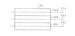
- 11A shows three regions 50a, 50b, 50c included in the standard image 50 and center lines 51c to 53c of each region.
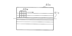
- FIG. 11B shows three regions 60a, 60b, 60c included in the reference image 60 and center lines of each region. 61c to 63c are shown. These three regions are regions obtained by subsequent division by the image dividing unit 201.
- the regions 60a to 60c include three regions 60d, 60e, and 60f each including a center line 61c to 63c and two upper and lower lines thereof.
- the correction amount determination unit 202 sets the standard image window on the center lines 51c, 52c, and 53c, sets the reference image window on the regions 60d, 60e, and 60f, and performs block matching to calculate the image shift amount.
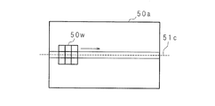
- the correction amount determination unit 202 sets a reference image window 50w corresponding to an image block of 3 ⁇ 3 pixels around the center line 51c of the region 50a in the reference image 50, and the center line of the region 60a in the reference image 60
- the reference image window 60w is set in three lines including 61c, the center line 61c, and the upper and lower two lines, and block matching is performed between the pixel blocks extracted by the standard image window 50w and the reference image window 60w, and the SAD value is calculated. calculate.
- the correction amount determination unit 202 sets the reference image window 50w for the center line 51c of the region 50a, and the reference image window 60w is positioned at the second line above the center line 61c of the region 60a. Set the window.
- the correction amount determination unit 202 performs block matching while moving the standard image window 50w and the reference image window 60w in the right direction, and calculates a minimum SAD value.
- the correction amount determining unit 202 has a length of 40 pixels from the left. The sum of the minimum SAD values is calculated in each search range.
- the correction amount determination unit 202 performs the same processing on the center lines 52c and 53c and the areas 60e and 60f, and calculates the sum of the minimum SAD values. Next, the correction amount determination unit 202 specifies a line when the sum of the minimum SAD values is smallest for each region having a width of 40 pixels, and sets the vertical image shift amount between the base image 50 and the reference image 60 to 40 pixels. Calculate for each width region. The correction amount determination unit 202 calculates an image shift amount for each of nine areas to be divided by the image dividing unit 204, and determines a correction amount for each region corresponding to the image shift amount.
- the correction amount determination unit 202 stores the determined correction amount for each region in a storage unit (not shown).
- the correction amount determination unit 202 performs the above process every time a correction instruction is received from the video scene detection unit 203, determines the correction amount for each region, and updates the correction amount for each region stored in the storage unit.
- the image dividing unit 201 reads the correction amount for each region from the storage unit of the correction amount determining unit 202, and divides the reference image according to the correction amount for each region. Specifically, when the image dividing unit 201 reads a standard image and a reference image from a built-in image memory (not shown), an image for each area of the reference image is stored from the storage area specified by the correction amount for each area. read out.
- FIG. 13A and 13B are explanatory diagrams showing a standard image and a reference image.
- FIG. 13A shows a standard image 50
- FIG. 13B shows a reference image 60.
- the image dividing unit 201 reads an image obtained by dividing each of the standard image 50 and the reference image 60 into, for example, nine regions from the image memory.
- the correction amount determination unit 202 determines that the correction amount of the region 60x of the reference image 60 corresponding to the region 50x in the standard image 50 is, for example, ⁇ 2 pixels
- the image dividing unit 201 uses the reference image 60 based on the correction amount. Is stored in the area corresponding to the area 60x, and is supplied to the parallax calculation unit 204.
- the image dividing unit 201 determines that the reference image 60 is based on the correction amount.
- An image included in an area corresponding to the area 60 y is read from the stored storage area, and provided to the parallax calculation unit 204.
- the image dividing unit 201 shifts the image reading position according to the correction amount determined by the correction amount determining unit 202.
- 14A and 14B are explanatory diagrams showing a standard image and a reference image.
- 14A shows a standard image 50
- FIG. 14B shows a reference image 60.
- the reference image 50 and the reference image 60 include the same subject images 51 and 61.
- the subject images 51 and 61 exist at different positions depending on the viewpoint position of the camera or the posture of the camera. Here, it is assumed that the second camera 2 is inclined with respect to the first camera 1.
- the image dividing unit 201 reads an image included in the region 60x in the reference image from the image memory with respect to the region 50x in the standard image 50.
- FIG. 15A and FIG. 15B are explanatory diagrams schematically showing image shift in the vertical direction of the subject image in one region of the standard image and the reference image.
- FIG. 15A schematically shows a state in which an image included in the region 50x of the standard image 50 and an image included in the region of the reference image 60 corresponding to the region 50x are overlapped.
- FIG. 15B schematically shows a state in which the image included in the region 50x of the reference image 50 and the image included in the region 60x are overlapped.
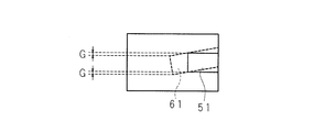
- FIG. 15A shows the base image 50 and the reference image 60 before correction
- FIG. 15B shows the base image 50 and the reference image 60 after correction.
- the image shift amount indicated by 15B is G.
- F> G correcting the reference image 60 reduces the image shift in the vertical direction between the base image and the reference image.
- the corresponding point search range is narrowed, so that the processing time required for the corresponding point search can be shortened.
- the divided reference image after dividing an image, a correction amount is obtained for each divided image, and the divided reference image is moved. Therefore, an area where no corresponding point exists may appear. For example, in the example shown in FIG. 8B, as a result of moving the divided reference image upward, there is no divided reference image corresponding to the lowermost part of the divided reference image, and similarly, the division reference corresponding to the uppermost part of the divided reference image is removed. The phenomenon that the image disappears occurs.
- the second embodiment since the image is divided after the correction amount is obtained, such a phenomenon can be prevented by changing the reading position in accordance with the correction amount in the divided region of the intermediate portion. Can be suppressed.
- the video scene detection unit 203 has a function as a correction instruction unit.
- the acceleration detection unit that detects an impact on the camera itself or a change in the camera position has a function of the correction instruction unit. May be. That is, when the acceleration detection unit provided in the camera detects an acceleration equal to or greater than a predetermined threshold, the acceleration detection unit may give a correction instruction to the correction amount determination unit 202. Thus, it is possible to determine that the shooting scene has changed, by moving the camera, and it is possible to correct when the positional relationship of the camera is broken and the arrangement is changed due to a large impact. It is not necessary to provide the acceleration detection unit having the function of the correction instruction unit in the camera itself, and it may be provided in a portable information device equipped with the camera. As a result, when a strong impact or the like is applied to the portable information device and a camera position shift occurs, the portable information device calculates a correction amount according to the motion detected by the acceleration detection unit, and corrects the camera position shift. be able to.
- the correction instruction unit does not send a correction instruction to the correction amount determination unit 202 for each frame, but in units of a plurality of preset frames or, for example, as required by the user
- the correction instruction may be sent in units of a plurality of frames set as described above.
- the correction amount determination unit 202 can reduce the processing amount as compared with the case where correction is performed for each frame. Furthermore, by reducing the processing amount of the correction amount determination unit 202, the power consumption of the portable information terminal can be saved.
- the correction instruction unit may determine whether the camera is activated and send a correction instruction only at the time of activation. Thus, by calculating the correction amount at the start-up before shooting, the parallax can always be calculated with high accuracy.
- the correction instruction unit may simply receive an instruction from the user and give the correction instruction to the correction amount determination unit 202.
- one region of a reference image image obtained from the first camera close to the left side of the subject
- a region of the corresponding reference image an image obtained from the second camera close to the right side with respect to the subject
- the region cut out from the reference image when calculating the parallax is set at a position where the reference image division position is shifted to the left by the maximum parallax in consideration of the maximum parallax of the subject.
- FIG. 16 is a block diagram illustrating a configuration example of a disparity calculating apparatus according to Embodiment 3.
- the first camera 1 and the second camera 2 capture the same subject at the same timing, and provide the captured pair of left and right reference images and reference images to the parallax calculation device 300.
- the parallax calculation device 300 receives the base image and the reference image captured by the first camera 1 and the second camera 2, and executes corresponding point search processing and parallax calculation processing using the base image and the reference image. Includes an image division unit 301, a correction amount determination unit 302, a video scene detection unit 303, an image reduction unit 304, a parallax calculation unit 305, and a parallax integration unit 306.
- the configurations and operations of the image division unit 301, the video scene detection unit 303, and the parallax calculation unit 305 are the same as those described in Embodiment 2, and thus description thereof is omitted.
- configurations and operations of the correction amount determination unit 302, the image reduction unit 304, and the parallax integration unit 306 will be described.
- FIG. 17A and 17B are explanatory diagrams schematically showing a standard image and a reference image.
- FIG. 17A shows a state where the standard image 70 is divided into two upper and lower regions
- FIG. 17B shows a state where the reference image 80 is divided into two upper and lower regions.
- correction amount calculation processing for the upper half area of the standard image 70 and the reference image 80 will be described.
- the correction amount calculation process for the lower half area of the reference image 70 and the reference image 80 is the same as the process for the upper half area, and thus description thereof is omitted.
- the correction amount determination unit 302 performs block matching on the horizontal lines 71 and 72 in the standard image 70 and the horizontal lines 81 and 82 in the reference image 80, calculates a vertical image shift amount, and performs correction on the reference image 80. Determine the correction amount. Specifically, as described in the second embodiment, the correction amount determination unit 302 sets a reference image window for extracting a 3 ⁇ 3 pixel block on the horizontal line 71 in the reference image 70 and refers to it. A reference image window for extracting a 3 ⁇ 3 pixel block is set on a horizontal line 81 in the image 80.
- the correction amount determination unit 302 performs block matching while moving the reference image window in the horizontal direction and moving the reference image window in the horizontal direction and the vertical direction, and the sum of the minimum SAD values is minimized. Is determined, the image shift amount in that case is obtained, and the correction amount is determined.
- the correction amount determination unit 302 corrects the correction amount of the reference image 80 determined for the horizontal line 71 in the standard image 70 and the correction amount of the reference image 80 determined for the horizontal line 72. Are different from each other, an average value of both correction amounts is given to the image dividing unit 301.
- the image dividing unit 301 divides the standard image 70 and the reference image 80 based on the correction amount received from the correction amount determining unit 302, and converts the divided standard image and the divided reference image into the image reducing unit 304. Give to.
- the image reduction unit 304 performs a reduction process on the division standard image and the division reference image. For example, the image reduction unit 304 halves the vertical and horizontal lengths of each of the division standard image and the division reference image, and reduces the image size to 1 ⁇ 4 of the image size before reduction. That is, the image reduction unit 304 sets the resolution of the division standard image and the division reference image to 1 ⁇ 4 of the resolution before the reduction. Since the number of pixels in the horizontal direction of the division standard image and the division reference image is halved, the parallax calculated by the parallax calculation unit 305 is also halved compared to the case where the division standard image and the division reference image are not reduced.
- the amount of vertical image shift between the divided standard image and the divided reference image is also halved. That is, when the image shift amount after correcting the reference image is G as shown in FIG. 15B, the image shift amount is further reduced to half, that is, G / 2 by performing the reduction process.
- the parallax integration unit 306 performs an enlargement process on the parallax received from the parallax calculation unit 305, and doubles the parallax. Examples of the enlargement process include bilinear interpolation and nearest neighbor interpolation.
- the image shift amount is reduced by reducing the image sizes of the division standard image and the division reference image.
- the image sizes of the divided standard image and the divided reference image are reduced.
- the division may be performed after the standard image and the reference image are reduced.
- the image shift amount is reduced in accordance with the reduction rate as both images are reduced. Therefore, the image shift amount can be calculated by performing block matching in a short range in the vertical direction of the image. Performing block matching on the reduced image in a short range in the vertical direction and calculating the image shift amount is the same as calculating the image shift amount in a wide range in the vertical direction with respect to the image before reduction. Therefore, it is easy to calculate the image shift amount when both images are largely shifted.
- the correction amount is determined using two horizontal lines in the base image and the reference image, but the correction amount may be determined using more horizontal lines.
- the median value of the correction amounts calculated for each line may be determined as the correction amount.
- FIG. 18 is a block diagram illustrating a configuration example of the parallax calculation apparatus according to the fourth embodiment.
- the first camera 1 and the second camera 2 capture the same subject at the same timing, and provide the captured pair of left and right reference images and reference images to the parallax calculation device 400.
- the parallax calculation device 400 inputs the standard image and the reference image captured by the first camera 1 and the second camera 2, and executes the corresponding point search process and the parallax calculation process using the standard image and the reference image.
- the parallax calculation device 400 includes an image division unit 401, a correction amount determination unit 402, a color information calculation unit 403, a parallax calculation unit 404, and a parallax integration unit 405.
- the configuration and operation of the image dividing unit 401, the parallax calculating unit 404, and the parallax integrating unit 405 are the same as those shown in the second embodiment, and thus description thereof is omitted.
- the color information calculation unit 403 inputs a reference image, analyzes the image for each region that the image dividing unit 401 is supposed to divide, and calculates color information. For example, the color information calculation unit 403 calculates an average of RGB pixel values (hereinafter referred to as “RGB average value”) of the RGB image included in each region, and outputs the RGB average value as color information. . From this color information, it is possible to know what kind of subject has many colors in each region. For example, in a region where the sky is the majority of the subject, the value B of the average value of RGB is high, and it can be seen that the color of the image in that region is mostly blue. The color information calculation unit 403 provides the color information to the correction amount determination unit 402.
- RGB average value RGB pixel values
- the correction amount determination unit 402 performs block matching for calculating the image shift amount.
- the color information is used to determine a color used for block matching for each region. For example, as described above, when the B value of the average value of RGB is high, it can be seen that the region has a lot of blue subjects, and when the correlation value is calculated using B, all the colors are similar. For this reason, all the correlation values become high, and there is a possibility that an accurate image shift amount is not calculated. Therefore, by calculating the degree of correlation using R or G, an accurate image shift amount can be calculated.
- the number of colors used to calculate the image shift amount according to the color information is determined by storing a color information reference table in an internal memory (not shown) and referring to the reference table.
- the color used in block matching may be determined.
- the average values of RGB may be compared, and block matching may be performed using the color having the smallest average value.
- block matching may be performed using the color having the smallest average value.
- the color information is the average value of RGB for each area.
- each area is further divided into a plurality of small areas based on the color information.
- the average value of RGB in the region having the largest area may be used as the color information.
- the pixel value of the RGB value of each small area is, for example, R is 200 or more and G and B are 50 or less, the color of the small area is red. If the number of small red areas is greater than or equal to a predetermined number, the area color may be treated as red.
- Embodiments 1 to 4 the parallax calculation apparatus using two cameras has been described as an example, but three or more cameras may be used. In other words, one reference camera may be determined, a reference image may be obtained from the camera, and a reference image may be obtained from another camera.
- Embodiments 1 to 4 it is possible to accurately calculate parallax data indicating the amount of image shift in the horizontal direction, but a configuration for calculating distance data based on the parallax data may be added. Specifically, when the camera parameters such as the base line length, the camera tilt, and the resolution, which are intervals between the cameras, are known, the parallax data is calculated, and then the distance data (You may make it the structure of the distance calculation apparatus which calculates depth data.
- Embodiments 1 to 4 an example in which two cameras are arranged by the parallel method has been shown, but the optical axes of the two cameras may be arranged so as to have congestion.
- the cameras are arranged so that the optical axes of the two cameras are converging, the corresponding points corresponding to the point of interest on the standard image are different from those on the reference image, unlike when the cameras are arranged using the parallel method. It does not necessarily exist on the left side of Therefore, in such a case, a corresponding point search is performed in the left and right directions on the reference image.
- the optical axes of the two cameras are congested, the captured image is distorted from the beginning, and the point of interest and the corresponding point do not exist on the same straight line. Cannot be calculated.
- the base image and the reference image are divided, the vertical position adjustment is performed, and the processing for searching the corresponding points in both the left and right directions on the reference image is performed, so that an accurate parallax is calculated. it can.
- Embodiments 1 to 4 can be applied to a camera system including two camera modules, or a mobile terminal, a display device, an in-vehicle camera system, a distance detection device, and the like including the camera system.
- an image captured by the camera may be input to a computer such as a personal computer and processed, or the image may be stored in a storage device, and the parallax or distance may be calculated using the image.
- FIG. 19 is a block diagram illustrating a configuration example of a disparity calculating apparatus according to Embodiment 5.
- the first camera 1 and the second camera 2 capture the same subject at the same timing, and provide the captured pair of left and right reference images and reference images to the parallax calculation device 500.
- an image of the first camera 1 positioned to the left of the subject is a reference image
- an image of the second camera 2 positioned to the right of the subject is a reference image.
- the first camera 1 and the second camera 2 are arranged so as to photograph a subject by a parallel method.
- the parallax calculation device 500 inputs the standard image and the reference image captured by the first camera 1 and the second camera 2, and executes the corresponding point search process and the parallax calculation process using the input standard image and reference image.
- the parallax calculation device 500 includes an image division unit 501, a condition setting unit 502, a correction amount determination unit 503, a correction amount analysis unit (difference calculation unit) 504, a parallax calculation unit 505, a parallax integration unit 506, and a storage unit 507.
- the configurations and operations of the parallax calculation unit 505 and the parallax integration unit 506 are the same as those described in Embodiment 1, and thus description thereof is omitted.
- the storage unit 507 is a memory that stores the correction amount for each region determined by the correction amount determination unit 202 in the second embodiment.
- the storage unit 507 is an image memory that stores the division standard image and the division reference image divided by the image division unit 501.
- the image dividing unit 501 divides the standard image and the reference image into a plurality of regions according to the number of divisions set by the condition setting unit 502, and stores the divided division standard image and the divided reference image in a predetermined region of the storage unit 507.
- the image dividing unit 501 gives the divided division standard image and the divided reference image to the correction amount determining unit 503 and the parallax calculating unit 505.
- the condition setting unit 502 sets the number of image divisions.
- the initial number of divisions is, for example, 9 (length 3 ⁇ width 3). That is, the image dividing unit 501 divides each of the standard image and the reference image into nine regions.
- the correction amount determination unit 503 acquires the division standard image and the division reference image from the image division unit 501 or the storage unit 507.
- the correction amount determination unit 503 calculates a vertical image shift amount between the divided reference image and the divided reference image, and determines a correction amount for reducing the calculated image shift for each region.
- the correction amount analysis unit 504 analyzes the correction amount for each region determined by the correction amount determination unit 503.
- the correction amount analysis unit 504 notifies the condition setting unit 502 to change the number of divisions of the image based on the analyzed correction amount for each region.
- the condition setting unit 502 resets the number of image divisions when receiving a notification regarding the change in the number of divisions from the correction amount analysis unit 503.
- the image dividing unit 501 again divides the standard image and the reference image into a plurality of areas according to the division number reset by the condition setting unit 502.
- the image division unit 501 gives the division standard image and the division reference image obtained by the division again to the correction amount determination unit 503 and the parallax calculation unit 505.
- FIG. 20A and 20B are explanatory diagrams illustrating a standard image and a reference image.
- FIG. 20A shows a reference image 507 that is a left image taken by the first camera 1.
- FIG. 20B shows a reference image 508 that is a right image taken by the second camera 2.
- the reference image 508 it is assumed that a barrel distortion due to a lens included in the second camera 2 exists. Therefore, an image portion or an image region closer to the left and right ends of the reference image 508 has a larger amount of deviation in the vertical direction with respect to the reference image 507 due to the influence of barrel distortion.
- the image dividing unit 501 divides the standard image 507 and the reference image 508 into nine as shown by dotted lines in FIGS. 20A and 20B.
- the correction amount determination unit 503 calculates a correction amount based on the standard image 507 and the reference image 508 that are divided into nine by the image dividing unit 501.
- the correction amount determination unit 503 gives the calculated correction amount data to the correction amount analysis unit 504.
- FIG. 21A and FIG. 21B are explanatory diagrams illustrating the correction amount of each region calculated by the correction amount determination unit.
- the numerical values in FIGS. 21A and 21B represent the correction amount (pixel) calculated by the correction amount determination unit 503. 21A and 21B, the sign + indicates that the direction in which the reference image 508 is shifted for correction is upward, and the sign-indicates that the direction in which the reference image 508 is shifted for correction is downward. means.
- FIG. 21A shows the correction amount calculated for each region corresponding to the first image division.
- FIG. 21B shows the correction amount calculated for each region corresponding to the re-divided image.
- the correction amount analysis unit 504 receives the correction amount calculated by the correction amount determination unit 503. Based on the received correction amount, the correction amount analysis unit 504 analyzes the difference in correction amount between the left and right adjacent image regions. For example, when attention is paid to the upper left area in FIG. 21A, the correction amount of the upper left area is +3. In addition, the correction amount in the right adjacent region (upper center region) with respect to the upper left region is zero. The absolute value of the difference between the correction amounts in each of these areas is 3. When the entire area in the image has a shift amount corresponding to the same direction, the correction amount in each area is almost the same. Therefore, the larger the absolute value of the difference in the correction amount in each area, the larger the image. You can see that it is distorted.
- FIG. 22 is an explanatory diagram schematically showing a state in which the upper left region and the subject image in FIGS. 20A and 20B are superimposed.
- the image distortion is large, as shown in FIG. 22, even if correction is performed so that the vertical shift in the upper left area is not near the center of the subject image, the shift remains on the left and right of the subject image, and the remaining shift The direction is also opposite to the left and right of the subject image. Therefore, when the distortion in the image is large, a method of dividing the image more finely by a number larger than the number of already divided images can be considered.
- a threshold for determining whether or not the correction amount analysis unit 504 performs image re-division is set in advance, and this threshold is set to 2, for example.
- the difference between the correction amounts of the upper left region and the upper central region in FIG. 21A is 3 which is larger than the threshold value 2 in the correction amount analysis unit 504, and thus the distortion between the upper left region and the upper central region is large. It is determined that subdivision is performed for each. Therefore, the correction amount analysis unit 504 notifies the condition setting unit 502 of the change in the number of divisions. Based on the notification from the correction amount analysis unit 504, the condition setting unit 502 increases the number of divisions in the region where the difference in the correction amount from the adjacent region is large.
- the image dividing unit 501 divides the standard image 507 and the reference image 508 again based on the division number of each area reset by the condition setting unit 502. Then, the correction amount determination unit 503 calculates and determines the correction amount more finely based on the division standard image and the divided reference image divided again by the image division unit 501.
- the condition setting unit 502 resets the number of divisions in the left and right directions to, for example, twice the initial value in each of the upper and lower image areas in FIGS. 20A and 20B.
- the number of divisions for re-division in the adjacent region where the distortion is large is not limited to twice the initial number, and may be more than twice.
- the image dividing unit 501 divides the standard image 507 and the reference image 508 again based on the division number of each area reset by the condition setting unit.
- the correction amount calculation unit 503 calculates the correction amount for each region divided again by the image dividing unit 501.
- FIG. 21B is an explanatory diagram showing the results.
- Embodiment 5 it is assumed that there is mold distortion on the camera lens. However, since the parallax calculation apparatus 500 increases the number of divisions in a region where the difference in correction amount is large, the parallax can be accurately calculated even if a pincushion distortion or pincushion distortion exists in the lens of the camera. it can.
- the threshold value for determining whether or not the correction amount analysis unit 504 divides the image again is 2.
- this threshold value may be appropriately changed according to parameters such as the resolution of the image, the block size when calculating parallax, and the like, and whether or not to reduce the image.
- the parallax calculation apparatus 500 may be provided with the means by which a user can change a threshold suitably according to these parameters.
- the parallax calculation apparatus 500 may store and manage the threshold value appropriately changed by the user in the storage unit 507. Further, the parallax calculation apparatus 500 may set a plurality of threshold values and change the number of divisions according to the set threshold values. The parallax calculation device 500 can increase the number of divisions as the difference in the correction amount from the adjacent region increases, thereby correcting the shift amount more accurately according to the distortion amount and making it easier to calculate the parallax.
- the correction amount can be adaptively calculated according to the image, which contributes to shortening of the processing amount, processing time, and the like.
Landscapes
- Physics & Mathematics (AREA)
- Engineering & Computer Science (AREA)
- General Physics & Mathematics (AREA)
- Electromagnetism (AREA)
- Radar, Positioning & Navigation (AREA)
- Remote Sensing (AREA)
- Computer Vision & Pattern Recognition (AREA)
- Theoretical Computer Science (AREA)
- Multimedia (AREA)
- Signal Processing (AREA)
- Image Processing (AREA)
- Measurement Of Optical Distance (AREA)
- Image Analysis (AREA)
- Length Measuring Devices By Optical Means (AREA)
- Testing, Inspecting, Measuring Of Stereoscopic Televisions And Televisions (AREA)
Abstract
二つの視点それぞれから得られた画像間の視差を算出する際、画像間の歪み又はずれの影響を抑え、精度の高い視差を簡易に算出する視差算出装置、距離算出装置及び視差算出方法を提供する。 視差算出装置100は、第一カメラ1から得られた基準画像及び第二カメラ2から参照画像を取得する。画像分割部101は、条件設定部102によって設定される分割条件に従い、基準画像及び参照画像それぞれを複数の領域に分割する。補正量決定部103は、分割された領域毎に画像ずれ量を算出し、その画像ずれ量に基づき補正量を決定する。視差算出部104は、補正量決定部103によって決定された補正量に基づいて画像分割部101から得られる分割基準画像及び分割参照画像の各領域に対して画像の補正を行い、補正後の画像に基づいて視差を求める。
Description
本発明は、複数のカメラで被写体を撮影し、各カメラ画像から視差を算出する視差算出装置、カメラ及び被写体間の距離を算出する距離算出装置及び視差算出方法に関する。
複数の視点から同一被写体をカメラで撮像して得られる複数の画像に基づいて立体画像又は自由視点画像を生成する撮像システムが知られている。この撮像システムでは、画像間の相対的なずれ量である視差から三角測量の原理を用いて被写体の距離情報(奥行き情報)を算出し、その距離情報に基づき、任意の仮想視点から見た画像を生成する処理が行われる。
2つの画像間の視差を算出する場合、一般的に、2つの画像間における対応点の検出が行われる。対応点を検出する方法としては、例えば、差分絶対値和(SAD:Sum Of Absolute Difference)を用いたSAD法又は差分二乗和(SSD:Sum of Squared Difference)を用いたSSD法が知られている。これらの方法では、先ず、2つの画像の内、一方の画像を基準画像とし、他方の画像を参照画像とする。また、基準画像内の注目点に対して、この注目点を含む領域を設定し、参照画像内にもその領域と同じ大きさの領域を複数設定する。そして、基準画像内の領域と、参照画像内の各領域との間の相関度をブロックマッチングにより求め、相関度が最も高い参照画像内の領域の中心点を当該注目点に対応する対応点として検出する。対応点の検出は、エピポーラ線上を探索することにより行われる。エピポーラ線とは、2つの視点及び空間中又は物体上の対象点を含む平面であるエピポーラ面が、それぞれの画像と交わった直線である。
図23は、エピポーラ面とエピポーラ線を示す模式図である。
空間中の対象点3を左カメラである第一カメラ1及び右カメラである第二カメラ2により撮影した場合を例にして説明する。この場合、エピポーラ線7及び8は、空間中の対象点3及び2つの視点(第一カメラ1及び第二カメラ2それぞれのレンズの中心)の3点と、それらを結ぶ3つの線分からなる三角形の平面(エピポーラ平面)4と、第一カメラ1が撮影した画像平面5及び第二カメラ2が撮影した画像平面6との交線のことである。一方の画像内の注目点に対応する他方の画像内の対応点はエピポーラ線上に存在するためエピポーラ線上を探索すれば対応点を検出できる。
図24A,Bは、第一カメラ1及び第二カメラ2の光軸が平行になるように第一カメラ1及び第二カメラ2を配置した場合を示す模式図である。この場合、エピポーラ線7及び8は両画像面において同じ高さの水平な直線になるため、両画像において同一ライン上で対応点を探索すればよい。
空間中の対象点3を左カメラである第一カメラ1及び右カメラである第二カメラ2により撮影した場合を例にして説明する。この場合、エピポーラ線7及び8は、空間中の対象点3及び2つの視点(第一カメラ1及び第二カメラ2それぞれのレンズの中心)の3点と、それらを結ぶ3つの線分からなる三角形の平面(エピポーラ平面)4と、第一カメラ1が撮影した画像平面5及び第二カメラ2が撮影した画像平面6との交線のことである。一方の画像内の注目点に対応する他方の画像内の対応点はエピポーラ線上に存在するためエピポーラ線上を探索すれば対応点を検出できる。
図24A,Bは、第一カメラ1及び第二カメラ2の光軸が平行になるように第一カメラ1及び第二カメラ2を配置した場合を示す模式図である。この場合、エピポーラ線7及び8は両画像面において同じ高さの水平な直線になるため、両画像において同一ライン上で対応点を探索すればよい。
しかし、2台のカメラの取り付け精度、あるいはレンズの歪み等により2つの画像間に画像ずれが生じる場合があり、各カメラにおけるエピポーラ線は、2つの画像内において同一ラインになるとは限らない。ずれが大きい場合、対応点を見つけることができず、正確な視差が算出できない領域が増える。正確に視差を算出するためには画像ずれを補正する必要があるが、例えば画面全体を移動して調整するといった単純な方法は補正の精度が低く、カメラの取り付け精度又はレンズの歪み等に起因した画像ずれを十分に補正することができない。
一方、特許文献1には、画像の回転ずれ又は並進ずれを幾何学的な座標変換であるアフィン変換を用いてリアルタイムで補正する装置が記載されている。また、特許文献2には、一方の画像内の第1のパターンと相関が最も高い第2のパターンを他方の画像内の複数の水平及び垂直ライン中から検出し、第1及び第2のパターンの第1及び第2の位置情報から視差を算出する装置が記載されている。この装置によれば、画像内の水平ライン及び垂直ライン上で対応点の探索を行うため、画像全体を補正しなくとも、画像ずれによる誤測距を防止することができる。
画像表示装置の解像度が高まるのに伴いカメラの解像度も高まっている。そのため高解像度画像に関しても精度の高い視差を算出する必要がある。しかし、特許文献1に記載の装置にあっては、画像全体に対して補正が行われるため、高解像度画像に対する補正に要する計算量は大きい。
特許文献2に記載の装置にあっては、画像に対して水平方向及び垂直方向の探索を行っているため、画素数が多い高解像度画像の場合、低解像度画像の場合と比べて視差が大きくなり、それに伴い対応点の探索範囲が広まる。つまり、画像の解像度が上がるにつれて対応点の探索範囲が広まり、対応点探索に要する計算量は膨大になる。
本発明は、斯かる事情に鑑みてなされたものであり、画像を複数の領域に分割し、領域毎に画像ずれを補正することにより、正確な視差を簡易に算出する視差算出装置、その正確な視差に基づきカメラ及び被写体間の距離を算出する距離算出装置及び視差算出方法を提供することを目的とする。
本発明の視差算出装置は、二つの視点から得られた画像間の画像ずれとしての視差を算出する視差算出装置において、前記画像それぞれを複数の領域に分割する画像分割部と、該画像分割部により分割された領域毎に二つの視点を結ぶ方向に垂直な方向における前記画像間の画像ずれ量を算出し、画像ずれ量に対応する補正量を決定する補正量決定部と、該補正量決定部により決定された補正量に基づき前記領域毎に画像を補正し、補正された画像に基づき視差を算出する視差算出部とを備えることを特徴とする。
本発明によれば、画像を複数の領域に分割し、垂直方向の画像ずれの補正を領域毎に行うため、正確な視差を簡易に算出することができる。
本発明の視差算出装置は、前記補正量決定部に補正量の決定を指示する補正指示部を更に備え、前記補正量決定部は、該補正指示部からの指示に従って補正量を決定するようにしてあることを特徴とする。
本発明によれば、外部条件に応じて適切なタイミングで画像ずれを補正することができる。
本発明の視差算出装置にあっては、前記補正指示部は、前記画像が動画像データである場合に、所定数のフレームを取得する度に、前記補正量決定部に補正量の決定を指示するようにしてあることを特徴とする。
本発明によれば、視差算出のための処理量を少なくすることができ、消費電力を削減することができる。
本発明の視差算出装置にあっては、前記補正指示部は、映像シーンの切り替えを検知し、映像シーンの切り替えを検知した場合、前記補正量決定部に補正量の決定を指示するようにしてあることを特徴とする。
本発明によれば、画像ずれ量が変わる映像シーンの切り替わり時に補正量を決定することができる。
本発明の視差算出装置にあっては、前記補正指示部は、加速度を検出し、所定の閾値以上の加速度を検出した場合、前記補正量決定部に補正量の決定を指示するようにしてあることを特徴とする。
本発明によれば、撮影シーンの変更又は外部からの衝撃等によりカメラが移動した場合の画像ずれを補正することができる。
本発明の視差算出装置は、前記各領域の補正量を記憶する記憶部を更に備え、前記補正量決定部は、該記憶部に記憶されている過去の補正量に基づき補正量を決定するようにしてあることを特徴とする。
本発明によれば、補正量を決定する処理を軽減できる。
本発明の視差算出装置は、前記領域毎の画像ずれの方向が同一方向である場合、前記視差算出部は、領域毎に算出された画像ずれ量の中から最小値を選択し、該最小値に従い画像全体を補正してから、領域毎に画像を補正するようにしてあることを特徴とする。
本発明によれば、領域毎の画像ずれの方向が同一方向である場合、最小の画像ずれ量に基づいて全領域に対する補正を行うことにより領域毎の画像ずれ量を減らしているため、視差を算出する際の対応点探索範囲を狭めることができ、そのための計算量を減らすことができる。
本発明の視差算出装置は、前記画像分割部は、大きさが異なるように領域を分割するようにしてあることを特徴とする。
本発明によれば、画像ずれ量が画像内の場所によって大きく異なるような場合であって、画像内の場所によって異なる大きさの領域を設定するため、画像ずれ量の大きさに応じ、きめ細かく補正を行うことができる。
本発明の視差算出装置は、前記画像分割部は、前記画像の中央部分の領域が大きく、前記画像の周辺部分の領域が小さくなるように分割するようにしてあることを特徴とする。
本発明によれば、レンズの歪みにより画像ずれ量が大きくなる画像周辺部分においては領域を小さくしているため、きめ細かく補正を行うことができ、精度の高い視差を得ることができる。
本発明の視差算出装置は、前記補正量決定部が決定した前記各領域の補正量に基づいて、隣接する領域間における補正量の差分を算出する差分算出部を備え、前記画像分割部は、該差分算出部が算出した領域間における差分が所定の閾値以上である場合、該領域各々を更に分割するようにしてあることを特徴とする。
本発明によれば、補正量の差分から特定される画像ずれ量が大きい領域を更に分割することにより、より正確に補正を行うことができる。
本発明の視差算出装置は、前記画像分割部は、前記差分算出部が算出した差分に応じて隣接する前記領域各々を分割する分割数を決定し、決定した分割数で更に分割するようにしてあることを特徴とする。
本発明によれば、レンズの歪みによる画像ずれ量が大きいほど分割数を多く設定することにより、正確に補正を行い、視差を算出し易くすることができる。
本発明の距離算出装置は、前記視差算出装置と、該視差算出装置により算出された視差に基づき、前記視点及び被写体間の距離を算出する距離算出部とを備えることを特徴とする。
本発明によれば、正確な被写体距離を簡易に算出することができる。
本発明の視差算出方法は、二つの視点から得られた画像それぞれを複数の領域に分割する画像分割ステップと、該画像分割ステップにより分割された領域毎に二つの視点を結ぶ方向に垂直な方向における前記画像間の画像ずれ量を算出し、画像ずれ量に対応する補正量を決定する補正量決定ステップと、該補正量決定ステップにより決定された補正量に基づき前記領域毎に画像を補正し、補正された画像に基づき、前記二つの視点から得られた画像間の視差を算出する視差算出ステップとを含むことを特徴とする。
本発明によれば、正確な視差を簡易に算出することができる。
本発明によれば、画像を複数の領域に分割し、領域毎に画像の補正を行うことにより、正確な視差を簡易に算出することができる。また、本発明によれば、その正確な視差に基づきカメラ及び被写体間の距離を算出することができる。
実施の形態1
以下、図面を参照して実施の形態1を具体的に説明する。
図1は、実施の形態1に係る視差算出装置の構成例を示すブロック図である。
第一カメラ1及び第二カメラ2は、同一の被写体を同じタイミングで撮影し、撮影した左右一対の基準画像及び参照画像を視差算出装置100に与える。ここでは、被写体に対して左寄りに位置する第一カメラの画像を基準画像、その被写体に対して右寄りに位置する第二カメラの画像を参照画像とする。また、第一カメラ及び第二カメラは平行法により配置されているものとする。平行法とは、2台のカメラの向き、すなわちそれらの光軸が略平行になるように、同じ高さで各カメラを配置する方法である。
視差算出装置100は、第一カメラ1及び第二カメラ2が撮影した基準画像及び参照画像を入力し、基準画像及び参照画像を用いて対応点探索処理及び視差算出処理を実行する。
視差算出装置100は、画像分割部101、条件設定部102、補正量決定部103、視差算出部104及び視差統合部105を有する。
以下、図面を参照して実施の形態1を具体的に説明する。
図1は、実施の形態1に係る視差算出装置の構成例を示すブロック図である。
第一カメラ1及び第二カメラ2は、同一の被写体を同じタイミングで撮影し、撮影した左右一対の基準画像及び参照画像を視差算出装置100に与える。ここでは、被写体に対して左寄りに位置する第一カメラの画像を基準画像、その被写体に対して右寄りに位置する第二カメラの画像を参照画像とする。また、第一カメラ及び第二カメラは平行法により配置されているものとする。平行法とは、2台のカメラの向き、すなわちそれらの光軸が略平行になるように、同じ高さで各カメラを配置する方法である。
視差算出装置100は、第一カメラ1及び第二カメラ2が撮影した基準画像及び参照画像を入力し、基準画像及び参照画像を用いて対応点探索処理及び視差算出処理を実行する。
視差算出装置100は、画像分割部101、条件設定部102、補正量決定部103、視差算出部104及び視差統合部105を有する。
画像分割部101は、条件設定部102により設定された分割数に従い基準画像及び参照画像を複数の領域に分割し、分割された基準画像(以下、分割基準画像と呼ぶ)及び分割された参照画像(以下、分割参照画像と呼ぶ)を画像メモリ(図示せず)の所定領域に記憶させる。
画像分割部101は、分割基準画像及び分割参照画像を補正量決定部103及び視差算出部104に与える。条件設定部102は、画像の分割数を設定する。分割数は、例えば、9個(縦3×横3)、16個(縦4×横4)、25個(縦5×横5)等である。つまり、画像分割部101は、基準画像及び参照画像それぞれを9領域、16領域又は25領域等に分割する。
画像分割部101は、分割基準画像及び分割参照画像を補正量決定部103及び視差算出部104に与える。条件設定部102は、画像の分割数を設定する。分割数は、例えば、9個(縦3×横3)、16個(縦4×横4)、25個(縦5×横5)等である。つまり、画像分割部101は、基準画像及び参照画像それぞれを9領域、16領域又は25領域等に分割する。
補正量決定部103は、画像分割部101から分割基準画像及び分割参照画像を取得する。補正量決定部103は、分割基準画像及び分割参照画像間に各カメラ1、2の取り付け精度又はそれらのレンズの精度の違い等に起因した垂直方向の画像ずれがある場合、分割基準画像及び分割参照画像間の画像ずれ量を算出し、画像ずれを軽減するための補正量を領域毎に決定する。補正量決定部103は、領域毎の補正量を視差算出部104に与える。ここで、垂直方向の画像ずれとは、例えば二台のカメラが離れている方向に対して垂直方向に存在する二つの撮像画像間のずれを意味する。これは、人が画像を見る場合で言うと、二つの視点を結ぶ方向に垂直な方向における画像間の画像ずれである。
視差算出部104は、補正量決定部103から領域毎の補正量を受け取り、その補正量に応じて画像メモリから分割基準画像及び分割参照画像を読み出す。具体的には、視差算出部104は、分割基準画像の各領域の画像が記憶された記憶領域から当該画像を読み出すと共に、分割参照画像の各領域の画像が記憶された記憶領域から分割参照画像を読み出し、補正量に応じて対応点探索を行うラインを変えて視差を算出する。
視差算出部104は、補正量決定部103から受け取った補正量に従って、分割参照画像を補正し、分割基準画像及び補正後の分割参照画像を用いて対応点探索を行い、領域毎に視差を算出する。視差算出部104は、算出した領域毎の視差を視差統合部105へ与える。なお、ここでの視差とは、右目及び左目で夫々見える像の位置の差異の意味であり、画像間における相対的な像のずれ量である。
視差統合部105は、視差算出部104から受け取った領域毎の視差を統合し、分割前の画像サイズに合わせた視差を求める。これを統合視差とする。
視差統合部105は、視差算出部104から受け取った領域毎の視差を統合し、分割前の画像サイズに合わせた視差を求める。これを統合視差とする。
まず、分割基準画像及び分割参照画像間に垂直方向の画像ずれが生じていない場合の視差の算出方法について説明する。
図2は、分割基準画像及び分割参照画像を模式的に示す説明図である。
図2Aは分割基準画像、図2Bは分割参照画像を示す。画像分割部101は、基準画像及び参照画像それぞれを例えば9領域に分割する。
図2は、分割基準画像及び分割参照画像を模式的に示す説明図である。
図2Aは分割基準画像、図2Bは分割参照画像を示す。画像分割部101は、基準画像及び参照画像それぞれを例えば9領域に分割する。
分割基準画像10及び分割参照画像20は同一の被写体を示す被写体画像11及び被写体画像21を含む。ここでは、被写体画像以外の背景部分は一様な色の背景であるとする。被写体画像11及び21は、3個の横長の矩形から成るとする。第一カメラ1及び第二カメラ2のレンズ位置(視点)が異なるため、被写体に対して右寄りに位置する第二カメラで撮影された分割参照画像20内の被写体画像21は、被写体に対して左寄りに位置する第一カメラで撮影された分割基準画像10内の被写体画像11に対して左方向にずれた位置に存在する。ここで分割基準画像10内の領域10a及び分割参照画像20内の領域20aに着目した場合、分割参照画像20の領域20a内の被写体画像21の一部は、分割基準画像10の領域10a内の被写体画像11の一部に対して左方向に幅Dずれた位置に存在する。幅Dは分割基準画像及び分割参照画像間の視差であり、画素数で表される。本例では、視差はD画素である。第一カメラ1及び第二カメラ2は輻輳をもたない平行な配置とされているため、視差は無限遠で0となり、カメラに近い被写体ほど大きな視差となる。輻輳とは、眼球運動の一種であり、対象に視線を交差させようとする両眼の動きであり、カメラにおいては各カメラの光軸が交わることを意味する。
図3は、図2に示す分割基準画像及び分割参照画像内の一領域、及びそれに含まれる被写体画像の一部を模式的に示す説明図である。
図3Aは分割基準画像内の一領域及びそれに含まれる被写体画像の一部、図3Bは分割参照画像内の一領域及びそれに含まれる被写体画像の一部、図3Cは図3A及び図3Bそれぞれが示す一領域及び被写体画像の一部を重ね合わせた状態を模式的に示す。
図3において、分割基準画像10内の領域10aは被写体画像11の一部を含み、分割参照画像20内の領域20aは被写体画像21の一部を含む。領域15aは、領域10a及び領域20aを重ね合わせた状態を仮想的に表したものである。領域15aからわかるように、領域10a及び領域20aには視差Dがある。
以下、視差Dを求める手法を説明する。
図3Aは分割基準画像内の一領域及びそれに含まれる被写体画像の一部、図3Bは分割参照画像内の一領域及びそれに含まれる被写体画像の一部、図3Cは図3A及び図3Bそれぞれが示す一領域及び被写体画像の一部を重ね合わせた状態を模式的に示す。
図3において、分割基準画像10内の領域10aは被写体画像11の一部を含み、分割参照画像20内の領域20aは被写体画像21の一部を含む。領域15aは、領域10a及び領域20aを重ね合わせた状態を仮想的に表したものである。領域15aからわかるように、領域10a及び領域20aには視差Dがある。
以下、視差Dを求める手法を説明する。
分割基準画像10内の領域10aに含まれる被写体画像11の一部及び分割参照画像20内の領域20aに含まれる被写体画像21の一部は、両画像内における垂直方向の座標が同一である水平ライン(以下、「同一ライン」と呼ぶ)上に位置する。そこで、視差算出部104は、分割基準画像10内の領域10aに含まれる被写体画像11の一部内に注目点(任意の点)を設定し、被写体画像21の一部内において注目点に対応する対応点を探索する。具体的には、視差算出部104は、被写体画像11の一部及び被写体画像21の一部に対して所定サイズの画素ブロックを用いたブロックマッチングを行う。視差算出部104は、ブロックマッチングを同一ライン上で行い、対応する画素ブロック間の相関度を求め、対応点を検出する。
視差算出部104は、相関度に基づいて注目点に対応する対応点を検出し、注目点及び対応点の距離、つまり視差を求める。視差算出部104は、分割基準画像10及び分割参照画像20内の他の領域においても同様にブロックマッチングを行うことにより対応点を検出し、注目点及び対応点から領域毎の視差を求める。
次に、上述の対応点探索について説明する。
図4は、ブロックマッチングを模式的に示す説明図である。
視差算出部104は、分割基準画像10内の領域10aに基準画像ウインドウ10wを設定し、分割参照画像20内の領域20aに参照画像ウインドウ20wを設定する。基準画像ウインドウ10w及び参照画像ウインドウ20wは同一ライン(点線)上に位置する。図4において、基準画像ウインドウ10w及び参照画像ウインドウ20wそれぞれは、領域10a及び領域20aに含まれる画像から3×3画素から成る画素ブロックを抽出する。注目点は、基準画像ウインドウ10wにより抽出される画素ブロックの重心位置(中心位置)に存在する。
図4は、ブロックマッチングを模式的に示す説明図である。
視差算出部104は、分割基準画像10内の領域10aに基準画像ウインドウ10wを設定し、分割参照画像20内の領域20aに参照画像ウインドウ20wを設定する。基準画像ウインドウ10w及び参照画像ウインドウ20wは同一ライン(点線)上に位置する。図4において、基準画像ウインドウ10w及び参照画像ウインドウ20wそれぞれは、領域10a及び領域20aに含まれる画像から3×3画素から成る画素ブロックを抽出する。注目点は、基準画像ウインドウ10wにより抽出される画素ブロックの重心位置(中心位置)に存在する。
視差算出部104は、基準画像ウインドウ10wを用いて抽出した画素ブロックから当該画素ブロックに含まれる画素の画素値を求める。同様に、視差算出部104は、参照画像ウインドウ20wを用いて抽出した画素ブロックから当該画素ブロックに含まれる画素の画素値を求める。
視差算出部104は、基準画像ウインドウ10w及び参照画像ウインドウ20wを水平方向に移動させながら、領域10a及び領域20aそれぞれから同一サイズ(3×3画素)の画素ブロックを抽出し、抽出した画素ブロックに対してブロックマッチングを行い、両画素ブロックの相関度を求める。相関度は、例えばSAD法による相関値演算により求めることができる。SAD法において相関度はSAD値で表される。SAD値とは、基準画像ウインドウ10w及び参照画像ウインドウ20wにより抽出された2つの画素ブロックにおける対応画素の画素値の差分絶対値を対応画素毎に求め、それらの差分絶対値を両ウインドウ内の全画素にわたって加算した値である。
基準画像ウインドウ10wにより抽出される画素ブロックが画素値X0~X8を有し、参照画像ウインドウ20wにより抽出される画素ブロックが画素値X’0~X’8を有する場合、SAD値は、次の式から得られる。

上式からわかるように、SAD値が小さいほど両画素ブロックの相関度は高く、SAD値が大きいほど相関度は低い。つまり、SAD値の大小に基づいて基準画像ウインドウ10w及び参照画像ウインドウ20wそれぞれにより抽出される画素ブロックの相関度が判定される。
尚、基準画像及び参照画像がモノクロ画像である場合には、モノクロ画像の画素値を用いてSAD値を算出し、基準画像及び参照画像がRGB画像の場合には、R(赤)、G(緑)、B(青)の内の少なくとも1色の画素値を用いてSAD値を算出すればよい。また、RGBの情報を輝度情報等に変換し、それを用いてSAD値を算出してもよい。
尚、基準画像及び参照画像がモノクロ画像である場合には、モノクロ画像の画素値を用いてSAD値を算出し、基準画像及び参照画像がRGB画像の場合には、R(赤)、G(緑)、B(青)の内の少なくとも1色の画素値を用いてSAD値を算出すればよい。また、RGBの情報を輝度情報等に変換し、それを用いてSAD値を算出してもよい。
図4を用いて対応点検出の処理を具体的に説明する。
視差算出部104は、先ず、基準画像ウインドウ10wを領域10aの右端から距離W離れた位置に設定し、その位置に基準画像ウインドウ10wを固定する。視差算出部104は、参照画像ウインドウ20wを領域20aの右端から距離(W+S)離れた位置に設定する。視差算出部104は、幅Sを探索範囲として、その探索範囲で参照画像ウインドウ20wを1画素数ずつ移動させながら基準画像ウインドウ10w内及び参照画像ウインドウ20w内の画素ブロック間でブロックマッチングを行う。
視差算出部104は、先ず、基準画像ウインドウ10wを領域10aの右端から距離W離れた位置に設定し、その位置に基準画像ウインドウ10wを固定する。視差算出部104は、参照画像ウインドウ20wを領域20aの右端から距離(W+S)離れた位置に設定する。視差算出部104は、幅Sを探索範囲として、その探索範囲で参照画像ウインドウ20wを1画素数ずつ移動させながら基準画像ウインドウ10w内及び参照画像ウインドウ20w内の画素ブロック間でブロックマッチングを行う。
尚、本実施の形態のようにカメラを平行に設置した場合には、視差はカメラ基線長が長いほど大きくなる。また、視差は被写体の奥行き距離が短くなるほど大きくなり、無限遠に近づくほど0に近づいていく。したがって、カメラ基線長又はカメラから被写体までの奥行き距離に応じて探索範囲を設定するのが好ましく、基線長が長くなるほど、あるいは奥行き距離が長くなるほど大きい値となる。例えば、探索範囲の最大値を予め設定しておき、被写体の奥行き距離が1メートル以下の場合には探索範囲を最大値に、1メートル以上の場合には探索範囲をその最大値の半分程度に設定するといった方法がある。
視差算出部104は、基準画像ウインドウ10wを領域10aの右端から距離W離れた位置に固定した状態で、参照画像ウインドウ20wを領域20aの右端から距離(W+S)離れた位置から、当該右端から距離W離れた位置まで右方向に1画素ずつ移動させながらブロックマッチングを行う。視差算出部104は、領域10a内に固定された基準画像ウインドウ10wにより抽出される画素ブロックと最も小さいSAD値(最小SAD値)、つまり、最も高い相関度を有する画素ブロックを領域20a内に特定する。基準画像ウインドウ10wにより抽出された画素ブロックの中心に位置する注目点に対応する対応点は、その特定された画素ブロックの中心に位置する。このようにして、視差算出部104は対応点を検出する。
視差算出部104は、領域毎に注目点とその対応点との距離から視差を算出し、基準画像10の全ての画素において視差を算出する。
尚、図4で示した例では、基準画像ウインドウ10w及び参照画像ウインドウ20wを3×3画素の画素ブロックに対応するサイズにしたが、各ウインドウのサイズを5×5画素又は9×9画素の画素ブロックに対応するサイズ、又は4×4画素等の縦横画素数が偶数である画素ブロックに対応するサイズなど様々なウインドウサイズとしてよい。
上記の例では、参照画像ウインドウ20wを右方向に移動させたが、左方向に移動させるようにしてもよい。つまり、領域20aの右端から距離W離れた位置から当該右端から距離(W+S)離れた位置まで左方向に1画素ずつ参照画像ウインドウ20wを移動させながらブロックマッチングを行ってもよい。
以上、分割基準画像及び分割参照画像間に垂直方向の画像ずれがない場合の対応点探索の手法を説明した。上述のように、画像ずれが存在しない場合、両画像間で同一ライン上を単に対応点探索を行えばよい。
上記の例では、参照画像ウインドウ20wを右方向に移動させたが、左方向に移動させるようにしてもよい。つまり、領域20aの右端から距離W離れた位置から当該右端から距離(W+S)離れた位置まで左方向に1画素ずつ参照画像ウインドウ20wを移動させながらブロックマッチングを行ってもよい。
以上、分割基準画像及び分割参照画像間に垂直方向の画像ずれがない場合の対応点探索の手法を説明した。上述のように、画像ずれが存在しない場合、両画像間で同一ライン上を単に対応点探索を行えばよい。
次に、分割基準画像及び分割参照画像間に垂直方向の画像ずれがある場合の対応点探索の手法を説明する。垂直方向の画像ずれは、レンズに歪みが存在する場合、カメラの取り付け精度が低く、本来であれば平行にずれなく配置すべきところでカメラ自体が傾いている場合、又はカメラが垂直方向にずれて配置されている場合などに生ずる。垂直方向の画像ずれをそのままにして上述のように同一ライン上で対応点探索を行った場合、対応点が同一ライン上に存在しないことにより対応点を誤検出する可能性が高く、正確な視差を算出できない。そこで、視差算出部104は、垂直方向の画像ずれを補正した後に対応点探索を行い、視差を算出する。以下、垂直方向の画像ずれを補正する処理等について詳細に説明する。
垂直方向の画像ずれがない場合、注目点とそれに対応する対応点は同一ライン上に存在するが、垂直方向の画像ずれがある場合、注目点とそれに対応する対応点は同一ライン上に存在しない。そこで、補正量決定部103は、分割基準画像及び分割参照画像間の垂直方向の画像ずれ量を領域毎に算出し、その領域毎の画像ずれ量に基づき分割参照画像の補正量を決定する。視差算出部104は、補正量決定部103から補正量を受け取り、その補正量に基づき分割参照画像を補正し、分割基準画像及び補正後の分割参照画像を用いた対応点探索を行う。
先ず、分割基準画像及び分割参照画像間に垂直方向の画像ずれがある状態を例に挙げて説明する。
図5は、分割基準画像及び分割参照画像を模式的に示す説明図である。
図5Aは分割基準画像、図5Bは分割参照画像を示す。画像分割部101は、基準画像及び参照画像それぞれを例えば9領域に分割する。
図5は、分割基準画像及び分割参照画像を模式的に示す説明図である。
図5Aは分割基準画像、図5Bは分割参照画像を示す。画像分割部101は、基準画像及び参照画像それぞれを例えば9領域に分割する。
分割基準画像30及び分割参照画像40それぞれは被写体画像31及び被写体画像41を含む。被写体画像31及び41は、例えば3個の横長の矩形から成る。第一カメラ1及び第二カメラ2のレンズ位置(視点)が異なり、且つ、各カメラの取り付け精度又はレンズの精度の違い等があるため、分割参照画像40内の被写体画像41は、分割基準画像30内の被写体画像31に対して左方向且つ下方向にずれた位置に存在する。つまり、分割基準画像30及び参照画像40間には垂直方向の画像ずれが存在する。
図6は、図5に示す分割基準画像及び分割参照画像内の一領域、及びそれに含まれる被写体画像の一部を模式的に示す説明図である。
図6Aは分割基準画像内の一領域及びそれに含まれる被写体画像の一部、図6Bは分割参照画像内の一領域及びそれに含まれる被写体画像の一部、図6Cは、図6A及び図6Bそれぞれが示す領域及び被写体画像を重ね合わせた状態を模式的に示す。
領域30aは被写体画像31の一部を含み、領域40aは被写体画像41の一部を含む。
図6Aは分割基準画像内の一領域及びそれに含まれる被写体画像の一部、図6Bは分割参照画像内の一領域及びそれに含まれる被写体画像の一部、図6Cは、図6A及び図6Bそれぞれが示す領域及び被写体画像を重ね合わせた状態を模式的に示す。
領域30aは被写体画像31の一部を含み、領域40aは被写体画像41の一部を含む。
図6Cからわかるように、領域40a内の被写体画像41は、領域30a内の被写体画像31に対して左方向にE画素数ずれ、且つ、下方向にF画素数ずれている。左方向のずれは視差であり、下方向のずれは各カメラの取り付け精度又はレンズの精度の違い等に起因した垂直方向の画像ずれである。このように部分的な垂直方向の画像ずれが生じている状態で上述の水平方向のブロックマッチングを行う場合、対応点を検出できず、正しい視差を算出できないことがある。被写体画像31の左端の垂直方向エッジにおける中央近傍部分の形状及び色は、被写体画像41の左端の形状及び色とほぼ同一であるため、当該部分に位置する注目点に対応する視差は、上述の水平方向のブロックマッチングにより正しく検出できる可能性がある。しかし、被写体画像31の左上角隅の部分に位置する注目点に対応する対応点は同一ライン上には存在しない為、誤検出される可能性が高い。そのため、分割基準画像30及び分割参照画像40の画像全体から得られる視差の確度は高くない。
続いて、分割基準画像30及び分割参照画像40間に大きな垂直方向の画像ずれが生じている状態を例に挙げて説明する。
図7は、分割基準画像及び分割参照画像内の一領域及びそれに含まれる被写体画像の一部を模式的に示す説明図である。
図7Aは分割基準画像内の一領域及びそれに含まれる被写体画像の一部、図7Bは分割参照画像内の一領域及びそれに含まれる被写体画像の一部を示す。
領域50aは分割基準画像30内の領域であり、領域60aは分割参照画像40内の領域である。領域50aは被写体画像51の一部を含み、領域60aは被写体画像61の一部を含む。
図7は、分割基準画像及び分割参照画像内の一領域及びそれに含まれる被写体画像の一部を模式的に示す説明図である。
図7Aは分割基準画像内の一領域及びそれに含まれる被写体画像の一部、図7Bは分割参照画像内の一領域及びそれに含まれる被写体画像の一部を示す。
領域50aは分割基準画像30内の領域であり、領域60aは分割参照画像40内の領域である。領域50aは被写体画像51の一部を含み、領域60aは被写体画像61の一部を含む。
図7からわかるように、領域60a内の被写体画像61は、領域50a内の被写体画像51に対して垂直方向に大きくずれている。分割基準画像30及び分割参照画像40間に完全な垂直方向の画像ずれが生じている状態で上述の水平方向のブロックマッチングを行った場合、対応点を誤検出する可能性は非常に高い。そのため、分割基準画像30及び分割参照画像40間に部分的な垂直方向の画像ずれがある場合と比べて、正確な視差を算出することが一層困難になる。
このように分割基準画像30及び分割参照画像40間に垂直方向の画像ずれがある場合、対応点を誤検出する可能性があり、正確な視差を算出することが困難になる。そこで、補正量決定部103は、分割基準画像30内の各領域の水平方向の中心線を基準にして分割基準画像30及び分割参照画像40間の垂直方向の画像ずれ量を領域毎に算出し、領域毎の画像ずれ量に基づき補正量を決定し、視差算出部104に与える。視差算出部104は、補正量決定部103から受け取った補正量に基づき分割参照画像40を補正し、補正後の分割参照画像を用いて対応点探索を行う。以下、その処理を具体的に説明する。
図8A及び図8Bは、垂直方向の画像ずれの補正について説明するための説明図である。
図8Aは分割基準画像及び分割参照画像内の一領域、図8Bは分割基準画像及び補正後の分割参照画像内の一領域を示す。
図8Aにおいて、分割基準画像30内の領域30aは被写体画像31の一部を含み、分割参照画像40内の領域40aは被写体画像41の一部を含む。
図8Aは分割基準画像及び分割参照画像内の一領域、図8Bは分割基準画像及び補正後の分割参照画像内の一領域を示す。
図8Aにおいて、分割基準画像30内の領域30aは被写体画像31の一部を含み、分割参照画像40内の領域40aは被写体画像41の一部を含む。
補正量決定部103は、分割基準画像30内の領域30aの中心線(点線)上に対して、3×3画素の画像ブロックを抽出する基準画像ウインドウを設定し、分割参照画像40内の領域40aの中心線上に対して3×3画素の画素ブロックを抽出する参照画像ウインドウを設定する。
補正量決定部103は、基準画像ウインドウの位置を固定し、参照画像ウインドウの位置を中心線に沿って水平方向に1画素ずつ移動させながらブロックマッチングを行い、各位置におけるSAD値を求める。ある1つの注目点に対応する対応点を検出するまでの探索範囲が例えば10画素の長さであれば、補正量決定部103は、10個のSAD値を求め、それらのSAD値の中から最小SAD値を選択する。
補正量決定部103は、基準画像ウインドウを水平方向に1画素数移動させて固定し、再び、参照画像ウインドウを水平方向に1画素数ずつ移動させながら、ブロックマッチングを行い最小SAD値の算出を繰り返していく。
このように、補正量決定部103は基準画像の各画素において探索範囲分のSAD値を求め、そのSAD値の中から最小SAD値を算出する。すなわち、補正量決定部103は、基準画像ウインドウを移動させた移動量である画素数と等しい数の最小SAD値を得ることになる。補正量決定部103は、得られた最小SAD値を全て加算し、最小SAD値の総和を求める。この最小SAD値の総和は、図8Aに示す状態でブロックマッチングしたことにより得られる値である。
次に、補正量決定部103は、分割参照画像40内の領域40aを上方向に1画素移動させ、上記と同じ処理を行い最小SAD値の総和を求める。移動は、基本的な対応点探索の方法で説明した同一ラインでの対応点探索と異なり、基準画像ウインドウの中心となるラインに対して、対応点探索を行う参照画像ウインドウの中心ラインを垂直方向にずらすことに相当し、これは簡易な処理である。ここでは、補正量決定部103は、分割参照画像40内の領域40aを上下方向に5画素ずつ移動させるものとする。
補正量決定部103は、1画素数移動させる毎に最小SAD値の総和を求める。その結果、補正量決定部103は、最小SAD値の総和をF個得る。補正量決定部103は、それらの最小SAD値の総和の中から最も小さい最小SAD値の総和を選択する。その最も小さい最小SAD値の総和が得られたときの領域40aの移動量が垂直方向の画像ずれ量に相当する。
例えば、補正量決定部103は、分割参照画像40を垂直方向に-5画素~+5画素の範囲で1画素ずつ移動させる毎に最小SAD値の総和を求め、最小SAD値の総和が最小となる場合を特定し、その場合の領域40aの移動量を画像ずれ量とする。領域40aを上方向に例えば2画素数移動したときの最小SAD値の総和が最も小さい場合、図8Bに示す画像ずれ量Fは2画素数であり、補正量を+2と決定する。尚、領域40aを上方向に移動する場合の補正量の符号を+とし、下方向に移動する場合の補正量の符号を-とする。
このように、補正量決定部103は、領域毎に分割基準画像と分割参照画像の画像ずれ量を求めて補正量を決定し、視差算出部104へ送る。視差算出部104は、分割参照画像を補正量にしたがって移動した後に対応点探索を行う。これにより、各画像の対応点が同一ライン上に存在する可能性が増加することから、補正前に対し正確な視差を算出することが可能となる。
視差算出部104は、領域毎に算出された視差を視差統合部105へ与える。視差統合部105は、視差算出部104から受け取った領域毎の視差を統合し、分割前の画像サイズに合わせた統合視差を求める。つまり、視差統合部105において、領域毎の視差は、基準画像の各画素に対応した視差データ(視差マップ)として統合される。
分割参照画像40内の全ての領域の画像が分割基準画像30内の対応領域の画像に対して、画像ずれ量は異なるが全て同じ方向(上方向又は下方向のいずれか一方)にずれている場合、補正量決定部103は、領域毎に求めた画像ずれ量の中から最小の画像ずれ量を選択し、その最小の画像ずれ量に応じて補正量を決定してもよい。その場合、視差算出部104は、分割参照画像内の全ての領域の画像に対して、その最小画像ずれ量分だけ移動した後に、移動後の画像に対する各領域の補正量に従い補正したのちに対応点探索を行い、視差を算出する。以下、その処理を具体的に説明する。
図9A及び図9Bは、分割参照画像内の9つの領域毎の画像ずれ量を示す説明図である。
図9Aは、補正前の分割参照画像内の9つの領域の画像ずれ量を領域毎に示す。ここでは、分割参照画像40内の領域1~3は、分割基準画像30内の領域1~3に対して下方向に3画素数ずれ、分割参照画像40内の領域4~6は、分割基準画像30内の領域4~6に対して下方向に4画素数ずれ、分割参照画像40内の領域7~9は、分割基準画像30内の領域7~9に対して下方向に5画素数ずれているものとする。この場合、最小画像ずれ量は3画素であるため、分割参照画像内の9つの領域全てを上方向に3画素数移動させる。
図9Aは、補正前の分割参照画像内の9つの領域の画像ずれ量を領域毎に示す。ここでは、分割参照画像40内の領域1~3は、分割基準画像30内の領域1~3に対して下方向に3画素数ずれ、分割参照画像40内の領域4~6は、分割基準画像30内の領域4~6に対して下方向に4画素数ずれ、分割参照画像40内の領域7~9は、分割基準画像30内の領域7~9に対して下方向に5画素数ずれているものとする。この場合、最小画像ずれ量は3画素であるため、分割参照画像内の9つの領域全てを上方向に3画素数移動させる。
図9Bは、分割参照画像の9つの領域全てを上方向に3画素数移動させた後の各領域の画像ずれ量を示す。図9Bからわかるように、分割参照画像の9つの領域の全てを3画素数上方向に移動させることにより、分割参照画像40内の領域1~3の画像ずれ量は0、領域4~6の画像ずれ量は1画素、領域7~9の画像ずれ量は2画素になる。つまり、分割参照画像内の全ての領域を最小の画像ずれ量分だけ移動させておくことにより、画像ずれ量の最大値は2画素になり、画像ずれ量は全体的に小さくなる。よって、次回の補正量算出の際には、上下方向により狭い範囲で画像ずれ量を算出すればよく、高解像度画像における処理量の削減に繋がる。また、例えばカメラ起動時には画像全体に対して前述の最小の画像ずれ量分の補正を行い画像ずれ量を小さくしておく。これにより、衝撃等がカメラに加わり新たな画像ずれが発生した場合、もともとの画像ずれ量を小さくしてある為、大きなずれが発生した場合でも比較的狭い上下方向の範囲で画像ずれ量を算出できる。
実施の形態1は、画素単位で画像ずれを補正する手法とは異なり、領域単位で画像ずれを補正しているため、画素数の多い画像、つまり高解像度画像を処理する場合であっても処理量が大幅に増えることはない。したがって、画像の解像度が高くなるにつれ、実施の形態1における処理量と、画素単位で画像ずれを補正する手法における処理量との差は大きくなる。
尚、補正量決定部103は分割参照画像40内の各領域を上下方向に所定範囲ずらすことにより垂直方向の画像ずれ量を算出するが、その所定範囲をどの程度にするかは、カメラの取り付け精度に応じて設定すればよい。例えば、カメラの取り付け精度が低い場合には広い範囲に設定し、精度が高い場合には狭い範囲に設定すればよく、本実施の形態で示した5画素に限定するものではない。また、本実施の形態では上下方向に画像ずれ量の算出を行っているが、いずれか一方の方向に画像ずれが発生しているか予め判明している場合は、上方向の範囲又は下方向の範囲のいずれか一方の範囲に対してのみ画像ずれ量の算出を行ってもよい。
また、本実施の形態では最初の補正量決定時に各領域で補正方向が同じであった場合、その各領域の補正量の最小値分補正しておくとしたが、これ以外にも、領域毎に前回の補正量を元に、その補正位置から相関値を算出して画像ずれ量を算出するようにしてもよい。例えば、ある領域で補正量が+2であった場合、この値を記憶装置に記憶させておき、次回の補正量決定時に、その補正量の位置から最小SAD値の総和の算出を始めてもよい。そして、その最小SAD値の総和が一定値(例えば、予め設定済みの規定値や、横のピクセル数とブロックサイズに応じた閾値)以下になった時点で画像ずれ量の算出をやめてもよい。この場合、前回の補正量付近で相関を調べ、充分な相関が得られた場合にはそれ以外のラインに対して相関を調べる為の探索を行わなくなる為、処理量が削減でき、すばやく補正量を決定することができる。
画像分割部101は、基準画像及び参照画像を上下左右均等に分割しなくてもよい。レンズの歪みによる画像ずれの場合、基準画像及び参照画像の端近傍の領域の画像ずれ量が大きいため、その領域での分割数を多くし、中央近辺の分割数を小さくしてもよい。画像内の位置に応じて分割数を異ならせることにより、画像ずれを画像内の位置に応じてきめ細かく補正することができ、対応点探索の精度を向上させることができる。
また、本実施の形態では被写体に対して左側に寄ったカメラである第一カメラの画像を基準画像、つまり第一カメラを基準として視差データを算出した。しかし、これに限らず、視差の関係から探索範囲の方向は変化するが、被写体に対して右側に寄ったカメラである第二カメラの画像を基準画像、つまり第二カメラを基準として視差データを算出してもよい。
また、本実施の形態では被写体に対して左側に寄ったカメラである第一カメラの画像を基準画像、つまり第一カメラを基準として視差データを算出した。しかし、これに限らず、視差の関係から探索範囲の方向は変化するが、被写体に対して右側に寄ったカメラである第二カメラの画像を基準画像、つまり第二カメラを基準として視差データを算出してもよい。
また、本実施の形態では、画像内の1ラインにおけるSAD値の総和が最小となる位置を特定することによって、基準画像及び参照画像間の画像ずれ量を算出したが、これ以外の手法を用いて画像ずれ量を算出してもよい。例えば、ブロックマッチング時に最小SAD値に近いSAD値が複数存在する場合、算出された視差の信頼度は低いとみなし、その視差をエラーとしてエラー処理する。このエラー処理を行うことにより、信頼度の高い視差だけを抽出し、抽出された信頼度の高い視差の数が最大となるように補正量を決定してもよい。また、SADに限らずSSDなどの他の手法を用いても良い。
また、例えばエッジ抽出などの特徴点抽出を行い、抽出した特徴点の対応度に従って補正量を決定してもよい。例えば、基準画像及び参照画像に対してエッジ検出処理を行い、基準画像及び参照画像それぞれのエッジ画像を作成する。次いで、各エッジ画像を領域分割し、領域毎にエッジの対応度を求める。基準画像及び参照画像の水平方向には視差が存在するため、基準画像及び参照画像のエッジ画像を領域毎にそのまま重ね合わせても、両画像のエッジの位置は一致しない。そこで、分割参照画像を領域毎に垂直方向に1画素移動する毎に、分割参照画像を水平方向に予め決められた探索範囲分移動する。そして、分割参照画像を移動させながら分割基準画像と分割参照画像とを重ね合わせ、エッジが一致した位置の数を算出する。この処理を繰り返し、エッジが一致した位置の数を求め、この数を基準画像及び参照画像の垂直方向の対応度とする。つまり、エッジが一致した位置の数が多い程、対応度が大きいと判断する。この対応度が最も大きくなる垂直方向の位置を特定することで、垂直方向の画像ずれ量を算出し、補正量を決定する。そして、その補正量に基づいて画像を補正することにより、正確な視差を算出することができる。
実施の形態2
以下、図面を参照して実施の形態2を具体的に説明する。
図10は、実施の形態2に係る視差算出装置の構成例を示すブロック図である。
第一カメラ1及び第二カメラ2は、同一の被写体を同じタイミングで撮影し、撮影した左右一対の基準画像及び参照画像を視差算出装置200に与える。視差算出装置200は、第一カメラ1及び第二カメラ2が撮影した基準画像及び参照画像を入力し、基準画像及び参照画像を用いて対応点探索処理及び視差算出処理を実行する
視差算出装置200は、画像分割部201、補正量決定部202、映像シーン検出部203、視差算出部204及び視差統合部205を有する。
以下、図面を参照して実施の形態2を具体的に説明する。
図10は、実施の形態2に係る視差算出装置の構成例を示すブロック図である。
第一カメラ1及び第二カメラ2は、同一の被写体を同じタイミングで撮影し、撮影した左右一対の基準画像及び参照画像を視差算出装置200に与える。視差算出装置200は、第一カメラ1及び第二カメラ2が撮影した基準画像及び参照画像を入力し、基準画像及び参照画像を用いて対応点探索処理及び視差算出処理を実行する
視差算出装置200は、画像分割部201、補正量決定部202、映像シーン検出部203、視差算出部204及び視差統合部205を有する。
画像分割部201及び補正量決定部202それぞれは、第一カメラ1及び第二カメラ2から基準画像及び参照画像を受け取る。基準画像及び参照画像は動画像である。
映像シーン検出部203は、第一カメラ1から基準画像を受け取り、基準画像に対して映像シーン解析を行い、映像シーンの切り替わりを検出する。映像シーンの切り替わりは、輝度又は色情報、又は第一カメラ1の動作において一時停止又は動作再開等に操作が行われたかによって検出する。映像シーン検出部203は、映像シーンの切り替わりを検出した場合、補正量決定部202に補正指示を与える。映像シーン検出部203は、補正量決定部202に補正指示を与える補正指示部としての機能を有する。
映像シーン検出部203は、第一カメラ1から基準画像を受け取り、基準画像に対して映像シーン解析を行い、映像シーンの切り替わりを検出する。映像シーンの切り替わりは、輝度又は色情報、又は第一カメラ1の動作において一時停止又は動作再開等に操作が行われたかによって検出する。映像シーン検出部203は、映像シーンの切り替わりを検出した場合、補正量決定部202に補正指示を与える。映像シーン検出部203は、補正量決定部202に補正指示を与える補正指示部としての機能を有する。
第一カメラ1及び第二カメラ2の位置が垂直方向にずれている場合、カメラと被写体との距離(奥行き距離)に応じて垂直方向に画像ずれが生じる。第一カメラ1及び第二カメラ2と被写体との距離が短いほど、基準画像及び参照画像間の垂直方向の画像ずれ量は大きくなり、その距離が長いほど基準画像及び参照画像間の垂直方向の画像ずれ量は小さくなる。つまり、第一カメラ1及び第二カメラ2と被写体との距離が大きく変わるような映像シーンの切り替え時、基準画像及び参照画像間の垂直方向の画像ずれ量は大きく変化する。そのため、映像シーンの切り替え前後の画像ずれ量は大きく異なる。そこで、補正量決定部202は、映像シーンが切り替わった後、基準画像及び参照画像間の垂直方向の画像ずれ量を算出し、その画像ずれ量に対応する補正量を決定し、画像分割部201に与える。画像分割部201は、補正量決定部202から受け取った補正量に基づき、基準画像及び参照画像を分割し、分割基準画像及び分割参照画像を視差算出部204に与える。視差算出部204は、分割基準画像及び分割参照画像を用いて対応点探索処理及び視差算出処理を行う。
実施の形態1では、画像分割部101が基準画像及び参照画像を所定の領域に分割した後、補正量決定部103は領域毎の補正量を決定する。これに対して、実施の形態2では、補正量決定部202は、画像分割部201で分割されることになる領域毎に画像ずれ量を算出し、その画像ずれ量に対応する補正量を決定し、画像分割部201に与える。画像分割部201は、補正量決定部202から補正量を受け取り、その補正量に基づいて基準画像及び参照画像を分割し、分割基準画像及び分割参照画像を視差算出部204に与える。視差算出部204及び視差統合部205の構成及び動作は、実施の形態1で示したものと同様であるため説明は省略する。
図11A及び図11Bは、基準画像及び参照画像を模式的に示す説明図である。
図11Aは、基準画像50に含まれる3領域50a、50b、50c及び各領域の中心線51c~53c、図11Bは、参照画像60に含まれる3領域60a、60b、60c及び各領域の中心線61c~63cを示す。この3領域は、後に画像分割部201により分割されることにより得られる領域である。図11Bにおいて、領域60a~60cは、中心線61c~63c及びそれらの上下2ラインから成る3つの領域60d、60e、60fを含む。
補正量決定部202は、基準画像ウインドウを中心線51c、52c、53c上に設定し、参照画像ウインドウを領域60d、60e、60f上に設定し、画像ずれ量を算出するためブロックマッチングを行う。
図11Aは、基準画像50に含まれる3領域50a、50b、50c及び各領域の中心線51c~53c、図11Bは、参照画像60に含まれる3領域60a、60b、60c及び各領域の中心線61c~63cを示す。この3領域は、後に画像分割部201により分割されることにより得られる領域である。図11Bにおいて、領域60a~60cは、中心線61c~63c及びそれらの上下2ラインから成る3つの領域60d、60e、60fを含む。
補正量決定部202は、基準画像ウインドウを中心線51c、52c、53c上に設定し、参照画像ウインドウを領域60d、60e、60f上に設定し、画像ずれ量を算出するためブロックマッチングを行う。
図12A及び図12Bは、ブロックマッチングを模式的に示す説明図である。
補正量決定部202は、基準画像50内の領域50aの中心線51cを中心にして3×3画素の画像ブロックに対応する基準画像ウインドウ50wを設定し、参照画像60内の領域60aの中心線61c及び中心線61c及びその上下2ラインを含む3ライン内に参照画像ウインドウ60wを設定し、基準画像ウインドウ50w及び参照画像ウインドウ60wそれぞれにより抽出される画素ブロック間でブロックマッチングを行い、SAD値を算出する。
補正量決定部202は、基準画像50内の領域50aの中心線51cを中心にして3×3画素の画像ブロックに対応する基準画像ウインドウ50wを設定し、参照画像60内の領域60aの中心線61c及び中心線61c及びその上下2ラインを含む3ライン内に参照画像ウインドウ60wを設定し、基準画像ウインドウ50w及び参照画像ウインドウ60wそれぞれにより抽出される画素ブロック間でブロックマッチングを行い、SAD値を算出する。
補正量決定部202は、領域50aの中心線51cに対して基準画像ウインドウ50wを設定し、領域60aの中心線61cの上の2ライン目に参照画像ウインドウ60wの中心が位置するように参照画像ウインドウを設定する。
補正量決定部202は、基準画像ウインドウ50w及び参照画像ウインドウ60wをそれぞれ右方向に移動させながらブロックマッチングを行い、最小SAD値を算出する。基準画像50及び参照画像60の水平方向の画素数が120画素であり、且つ、画像分割部201による水平方向の分割数が3である場合、補正量決定部202は、左から40画素の長さ毎の探索範囲で最小SAD値の総和を算出する。補正量決定部202は、同様な処理を中心線52c、53c及び領域60e、60fに対して行い、最小SAD値の総和を算出する。次いで、補正量決定部202は、最小SAD値の総和が最も小さくなるときのラインを40画素幅の領域毎に特定し、基準画像50及び参照画像60間の垂直方向の画像ずれ量を40画素幅の領域毎に算出する。
補正量決定部202は、画像分割部204で分割されることになる9個の領域毎の画像ずれ量を算出し、それらの画像ずれ量に対応する領域毎の補正量を決定する。
補正量決定部202は、基準画像ウインドウ50w及び参照画像ウインドウ60wをそれぞれ右方向に移動させながらブロックマッチングを行い、最小SAD値を算出する。基準画像50及び参照画像60の水平方向の画素数が120画素であり、且つ、画像分割部201による水平方向の分割数が3である場合、補正量決定部202は、左から40画素の長さ毎の探索範囲で最小SAD値の総和を算出する。補正量決定部202は、同様な処理を中心線52c、53c及び領域60e、60fに対して行い、最小SAD値の総和を算出する。次いで、補正量決定部202は、最小SAD値の総和が最も小さくなるときのラインを40画素幅の領域毎に特定し、基準画像50及び参照画像60間の垂直方向の画像ずれ量を40画素幅の領域毎に算出する。
補正量決定部202は、画像分割部204で分割されることになる9個の領域毎の画像ずれ量を算出し、それらの画像ずれ量に対応する領域毎の補正量を決定する。
補正量決定部202は、決定した領域毎の補正量を内蔵する記憶部(図示せず)に記憶させる。補正量決定部202は、映像シーン検出部203から補正指示を受ける度に、上記処理を行い、領域毎の補正量を決定し、記憶部に記憶している領域毎の補正量を更新する。
画像分割部201は、補正量決定部202の記憶部から領域毎の補正量を読み出し、その領域毎の補正量に応じて参照画像を分割する。具体的には、画像分割部201は、内蔵する画像メモリ(図示せず)から基準画像及び参照画像を読み出す際、領域毎の補正量により特定される記憶領域から参照画像の領域毎の画像を読み出す。
図13A及び図13Bは、基準画像及び参照画像を示す説明図である。
図13Aは基準画像50、図13Bは参照画像60を示す。
画像分割部201は、基準画像50及び参照画像60それぞれが例えば9領域に分割された画像を画像メモリから読み出す。補正量決定部202が基準画像50内の領域50xに対応する参照画像60の領域60xの補正量を例えば-2画素と決定した場合、画像分割部201は、その補正量に基づき、参照画像60が記憶されている記憶領域から領域60xに対応する領域に含まれる画像を読み出し、視差算出部204へ与える。
図13Aは基準画像50、図13Bは参照画像60を示す。
画像分割部201は、基準画像50及び参照画像60それぞれが例えば9領域に分割された画像を画像メモリから読み出す。補正量決定部202が基準画像50内の領域50xに対応する参照画像60の領域60xの補正量を例えば-2画素と決定した場合、画像分割部201は、その補正量に基づき、参照画像60が記憶されている記憶領域から領域60xに対応する領域に含まれる画像を読み出し、視差算出部204へ与える。
補正量決定部202が基準画像50の領域50yに対応する参照画像60の領域60yの補正量を例えば-2画素と決定した場合、画像分割部201は、その補正量に基づき、参照画像60が記憶されている記憶領域から領域60yに対応する領域に含まれる画像を読み出し、視差算出部204へ与える。このように、画像分割部201は、画像メモリから参照画像60を読み出す際、補正量決定部202が決定した補正量に応じて画像の読み出し位置をずらす。
図14A及び図14Bは、基準画像及び参照画像を示す説明図である。
図14Aは基準画像50、図14Bは参照画像60を示す。
基準画像50及び参照画像60内には同一の被写体画像51及び61が含まれる。被写体画像51及び61は、カメラの視点位置又はカメラの姿勢により異なる位置に存在する。ここでは、第一カメラ1に対し第二カメラ2が傾いているものとする。上述したように、画像分割部201は、基準画像50内の領域50xに対して、参照画像内の領域60xに含まれる画像を画像メモリから読み出す。
図14Aは基準画像50、図14Bは参照画像60を示す。
基準画像50及び参照画像60内には同一の被写体画像51及び61が含まれる。被写体画像51及び61は、カメラの視点位置又はカメラの姿勢により異なる位置に存在する。ここでは、第一カメラ1に対し第二カメラ2が傾いているものとする。上述したように、画像分割部201は、基準画像50内の領域50xに対して、参照画像内の領域60xに含まれる画像を画像メモリから読み出す。
図15A及び図15Bは、基準画像及び参照画像の一領域における被写体画像の垂直方向の画像ずれを模式的に示す説明図である。
図15Aは、基準画像50の領域50xに含まれる画像及び領域50xに対応する参照画像60の領域に含まれる画像を重ねた状態を模式的に示す。図15Bは基準画像50の領域50xに含まれる画像及び領域60xに含まれる画像を重ねた状態を模式的に示す。換言すると、図15Aは基準画像50及び補正前の参照画像60を示し、図15Bは基準画像50及び補正後の参照画像60を示す。
図15Aは、基準画像50の領域50xに含まれる画像及び領域50xに対応する参照画像60の領域に含まれる画像を重ねた状態を模式的に示す。図15Bは基準画像50の領域50xに含まれる画像及び領域60xに含まれる画像を重ねた状態を模式的に示す。換言すると、図15Aは基準画像50及び補正前の参照画像60を示し、図15Bは基準画像50及び補正後の参照画像60を示す。
基準画像50内に含まれる被写体画像51及び参照画像60内に含まれる被写体画像61の左側角部分の垂直方向の画像ずれ量を比較した場合、図15Aで示す画像ずれ量はFであり、図15Bで示す画像ずれ量はGである。ここでF>Gであるため、参照画像60を補正することにより、基準画像及び参照画像間の垂直方向の画像ずれは減少する。それにより対応点探索の範囲が狭まるため、対応点探索に要する処理時間を短くすることができる。
実施の形態1では画像を分割した後、分割画像毎に補正量を求め、分割参照画像を移動するため、対応点の存在しない領域が出てくる場合がある。例えば、図8Bに示す例では、分割参照画像を上方向に移動させた結果、分割基準画像の最下部に対応する分割参照画像がなくなり、同様に、分割参照画像の最上部に対応する分割基準画像がなくなる現象が生じる。これに対して、実施の形態2では、補正量を求めた後に画像を分割するため、中間部分の分割領域では、補正量に応じて読出し位置を変更することで、そのような現象の発生を抑えることができる。
尚、実施の形態2では、映像シーン検出部203に補正指示部としての機能をもたせているが、カメラ自体への衝撃又はカメラ位置の変化を検出する加速度検出部に補正指示部の機能をもたせてもよい。すなわち、カメラに設けられた加速度検出部が所定の閾値以上の加速度を検出した場合、加速度検出部が補正量決定部202に補正指示を与えるようにしてもよい。これにより、撮影シーンが変わったことをカメラの移動によって判断することができる他、大きな衝撃を受けカメラの位置関係が崩れて配置が変わったときに補正することが可能となる。
補正指示部の機能を有する加速度検出部をカメラ自体に設ける必要はなく、カメラを搭載した携帯情報機器に設けてもよい。これによって、携帯情報機器に強い衝撃等が加わり、カメラの位置ずれが起きた場合、携帯情報機器は、加速度検出部が検出した動きに応じて補正量を算出し、カメラの位置ずれを補正することができる。
補正指示部の機能を有する加速度検出部をカメラ自体に設ける必要はなく、カメラを搭載した携帯情報機器に設けてもよい。これによって、携帯情報機器に強い衝撃等が加わり、カメラの位置ずれが起きた場合、携帯情報機器は、加速度検出部が検出した動きに応じて補正量を算出し、カメラの位置ずれを補正することができる。
補正指示部は、画像が動画像データであった場合に補正量決定部202に対してフレーム毎に補正指示を送るのではなく、予め設定された複数のフレーム単位又は、例えばユーザによって必要に応じて設定された複数のフレーム単位に補正指示を送ってもよい。このように複数のフレーム単位に補正指示を送ることにより、補正量決定部202は、フレーム毎に補正を行う場合よりも処理量を減らすことができる。更に、補正量決定部202の処理量を減らすことにより、携帯情報端末の消費電力を節約させることができる。また、補正指示部はカメラの起動を判断し、起動時のみ補正指示を送ってもよい。このように撮影前の起動時に補正量の算出を行うことによって、常に精度良く視差を算出できるようになる。
補正指示部は、単にユーザからの指示を受け取り、補正指示を補正量決定部202に与えるようにしてもよい。
補正指示部は、単にユーザからの指示を受け取り、補正指示を補正量決定部202に与えるようにしてもよい。
本実施の形態では、説明の簡略化のため、図13に示すように、領域分割を行う際に、基準画像(被写体に対して左側に寄った第一カメラから得られる画像)の一領域と、対応する参照画像(被写体に対して右側に寄った第二カメラから得られ画像)の一領域とは、各画像の横端から等距離の位置で分割されるようにしている。しかし実際には、基準画像の対応点は、参照画像上ではより左側の位置に存在する。そのため、視差算出時に参照画像から切り出す領域は、被写体の最大視差を考慮し、参照画像の分割位置を左側に最大視差分ずらしたところに設定されるのが好ましい。そのように領域を設定しない場合、基準画像内の領域内の左端付近に関しては、参照画像から切り出した領域内に対応点が含まれない状況が起こり、正しい視差が算出できなくなる。このように基準画像の領域に対応する参照画像の領域を左側にずらして分割することにより、視差の算出できない領域を減少させることができる。また、SADの場合、左右とも分割する領域をウインドウサイズ分大きく設定し、分割する各領域の一部が重複するように切り出した方が、正確なSAD値を算出することができる。
また、縦方向に画像ずれが存在する場合、被写体距離に応じて縦方向に視差が存在することになる。すなわち、被写体距離が短いほど上下の画像ずれ量が大きくなり、被写体距離が長いほど上下の画像ずれ量が小さくなる。そのため、被写体距離が大きく変わるような映像シーンの切り替え時において補正量を決定することは有効である。尚、縦方向の画像ずれの影響以外にも回転又は歪みの影響があるため、前述のように被写体距離に応じて画像ずれ量の大小が決定されるとは限らないが、映像シーン切り替え毎に画像ずれ量が変化することには変わりはない。よって、映像シーン切り替え毎に画像ずれ量を算出し、補正量を決定することは有効である。
実施の形態3
以下、図面を参照して実施の形態3を具体的に説明する。
図16は、実施の形態3に係る視差算出装置の構成例を示すブロック図である。
第一カメラ1及び第二カメラ2は、同一の被写体を同じタイミングで撮影し、撮影した左右一対の基準画像及び参照画像を視差算出装置300に与える。視差算出装置300は、第一カメラ1及び第二カメラ2が撮影した基準画像及び参照画像を入力し、基準画像及び参照画像を用いて対応点探索処理及び視差算出処理を実行する
視差算出装置300は、画像分割部301、補正量決定部302、映像シーン検出部303、画像縮小部304、視差算出部305及び視差統合部306を有する。
以下、図面を参照して実施の形態3を具体的に説明する。
図16は、実施の形態3に係る視差算出装置の構成例を示すブロック図である。
第一カメラ1及び第二カメラ2は、同一の被写体を同じタイミングで撮影し、撮影した左右一対の基準画像及び参照画像を視差算出装置300に与える。視差算出装置300は、第一カメラ1及び第二カメラ2が撮影した基準画像及び参照画像を入力し、基準画像及び参照画像を用いて対応点探索処理及び視差算出処理を実行する
視差算出装置300は、画像分割部301、補正量決定部302、映像シーン検出部303、画像縮小部304、視差算出部305及び視差統合部306を有する。
画像分割部301、映像シーン検出部303及び視差算出部305の構成及び動作は、実施の形態2で示したものと同様であるため説明は省略する。
以下、補正量決定部302、画像縮小部304及び視差統合部306の構成及び動作を説明する。
以下、補正量決定部302、画像縮小部304及び視差統合部306の構成及び動作を説明する。
図17A及び図17Bは、基準画像及び参照画像を模式的に示した説明図である。
図17Aは基準画像70を上下2つの領域に分割した状態を示し、図17Bは参照画像80を上下2つの領域に分割した状態を示す。以下、基準画像70及び参照画像80の上半分の領域に対する補正量の算出処理について説明する。基準画像70及び参照画像80の下半分の領域に対する補正量の算出処理は、上半分の領域に対する処理と同様であるため説明は省略する。
図17Aは基準画像70を上下2つの領域に分割した状態を示し、図17Bは参照画像80を上下2つの領域に分割した状態を示す。以下、基準画像70及び参照画像80の上半分の領域に対する補正量の算出処理について説明する。基準画像70及び参照画像80の下半分の領域に対する補正量の算出処理は、上半分の領域に対する処理と同様であるため説明は省略する。
補正量決定部302は、基準画像70内の水平ライン71及び72上及び参照画像80内の水平ライン81及び82上でブロックマッチングを行い、垂直方向の画像ずれ量を算出し、参照画像80に対する補正量を決定する。具体的には、実施の形態2で説明したように、補正量決定部302は、基準画像70内の水平ライン71上に3×3画素の画素ブロックを抽出する基準画像ウインドウを設定し、参照画像80内の水平ライン81上に3×3画素の画素ブロックを抽出する参照画像ウインドウを設定する。
補正量決定部302は、実施の形態2と同様に、基準画像ウインドウを水平方向に移動させると共に参照画像ウインドウを水平方向及び垂直方向に移動させながらブロックマッチングを行い、最小SAD値の総和が最小となる場合を特定し、その場合の画像ずれ量を求め、補正量を決定する。
実施の形態3では、補正量決定部302は、基準画像70内の水平ライン71に対して決定された参照画像80の補正量と、水平ライン72に対して決定された参照画像80の補正量とが異なる場合、両補正量の平均値を画像分割部301に与える。
画像分割部301は、実施の形態2と同様に、補正量決定部302から受け取った補正量に基づいて基準画像70及び参照画像80を分割し、分割基準画像及び分割参照画像を画像縮小部304へ与える。
画像縮小部304は、分割基準画像及び分割参照画像に対して縮小処理を行う。例えば、画像縮小部304は、分割基準画像及び分割参照画像それぞれの縦横長を半分にし、それらの画像サイズを縮小前の画像サイズの1/4にする。つまり、画像縮小部304は、分割基準画像及び分割参照画像の解像度を縮小前の解像度の1/4にする。分割基準画像及び分割参照画像の水平方向の画素数は半分になるため、分割基準画像及び分割参照画像を縮小しない場合と比べて、視差算出部305により算出される視差も半分になる。一方、分割基準画像及び分割参照画像の垂直方向の画素数も半分になるため、分割基準画像及び分割参照画像間の垂直方向の画像ずれ量も半分になる。つまり、図15Bで示したように参照画像を補正した後の画像ずれ量がGである場合、縮小処理を行うことで更に画像ずれ量は半分、つまりG/2になる。
画像縮小部304により視差が半分になったため、視差統合部306は、視差算出部305から受け取った視差に対して拡大処理を施し、その視差を2倍にする。拡大処理としては、例えば、バイリニア補間又はニアレストネイバー補間等がある。
実施の形態3では、分割基準画像及び分割参照画像の画像サイズを縮小することにより画像ずれ量を小さくする。その結果、画像ずれ量が小さくなることで視差が算出できる可能性が上がるとともに、対応点探索の検索範囲が狭まり、対応点探索に要する処理時間を短くすることができる。
尚、上記例では、分割基準画像及び分割参照画像の画像サイズを縮小しているが、基準画像及び参照画像を縮小した後に分割を行ってもよい。予め基準画像及び参照画像を所定の縮小率で縮小した場合、両画像の縮小に伴い画像ずれ量も縮小率に応じて小さくなる。よって、画像の上下方向の短い範囲でブロックマッチングを行うことで画像ずれ量を算出できる。縮小後の画像に対して上下方向の短い範囲でブロックマッチングを行い画像ずれ量を算出することは、縮小前の画像に対して上下方向の広い範囲で画像ずれ量を算出することと同じであるため、両画像が大きくずれている場合の画像ずれ量の算出が容易になる。また、上記例では、基準画像及び参照画像内の2つの水平ラインを用いて補正量を決定したが、より多くの水平ラインを用いて補正量を決定してもよい。例えば、3つの水平ラインを用いて補正量を決定する場合、ライン毎に算出される補正量の中央値を補正量として決定してもよい。
実施の形態4
以下、図面を参照して実施の形態4を具体的に説明する。
図18は、実施の形態4に係る視差算出装置の構成例を示すブロック図である。
第一カメラ1及び第二カメラ2は、同一の被写体を同じタイミングで撮影し、撮影した左右一対の基準画像及び参照画像を視差算出装置400に与える。視差算出装置400は、第一カメラ1及び第二カメラ2が撮影した基準画像及び参照画像を入力し、基準画像及び参照画像を用いて対応点探索処理及び視差算出処理を実行する。
視差算出装置400は、画像分割部401、補正量決定部402、色情報算出部403、視差算出部404及び視差統合部405を有する。
以下、図面を参照して実施の形態4を具体的に説明する。
図18は、実施の形態4に係る視差算出装置の構成例を示すブロック図である。
第一カメラ1及び第二カメラ2は、同一の被写体を同じタイミングで撮影し、撮影した左右一対の基準画像及び参照画像を視差算出装置400に与える。視差算出装置400は、第一カメラ1及び第二カメラ2が撮影した基準画像及び参照画像を入力し、基準画像及び参照画像を用いて対応点探索処理及び視差算出処理を実行する。
視差算出装置400は、画像分割部401、補正量決定部402、色情報算出部403、視差算出部404及び視差統合部405を有する。
画像分割部401、視差算出部404、視差統合部405の構成及び動作は、実施の形態2で示したものと同様であるため説明は省略する。
以下、補正量決定部402及び色情報算出部403の構成及び動作を説明する。
色情報算出部403は基準画像を入力し、画像分割部401が分割すると想定される領域毎に、画像を解析し色情報を算出する。例えば、色情報算出部403は、各領域に含まれるRGB画像のRGBそれぞれの画素値の平均(以下、「RGBの平均値」と呼ぶ)を算出し、RGBの平均値を色情報として出力する。この色情報からは、各領域内においてどのような色合いの被写体が多いかがわかる。例えば、被写体として空が大半を占める領域においては、RGBの平均値のBの値が高くなるため、その領域の画像の色は大半が青色であることがわかる。色情報算出部403は、色情報を補正量決定部402に与える。
色情報算出部403は基準画像を入力し、画像分割部401が分割すると想定される領域毎に、画像を解析し色情報を算出する。例えば、色情報算出部403は、各領域に含まれるRGB画像のRGBそれぞれの画素値の平均(以下、「RGBの平均値」と呼ぶ)を算出し、RGBの平均値を色情報として出力する。この色情報からは、各領域内においてどのような色合いの被写体が多いかがわかる。例えば、被写体として空が大半を占める領域においては、RGBの平均値のBの値が高くなるため、その領域の画像の色は大半が青色であることがわかる。色情報算出部403は、色情報を補正量決定部402に与える。
補正量決定部402では、画像ずれ量を算出するためのブロックマッチングを行うが、その際に色情報を用いて、ブロックマッチングに用いる色を領域毎に決定する。例えば、前述のようにRGBの平均値のBの値が高い場合、青色の被写体が多い領域であることがわかり、Bを使って相関値を算出した場合、どれも似たような色であるため、相関値がどれも高くなり、正確な画像ずれ量が算出されない可能性がある。そこで、R又はGを用いて相関度を算出することで、正確な画像ずれ量を算出できるようになる。
尚、色情報に応じて何色を利用して画像ずれ量を算出するかは、予め内部メモリ(図示せず)に色情報の参照テーブルを格納しておき、その参照テーブルを参照することにより、ブロックマッチングで使用する色を決定するようにすればよい。また、RGBそれぞれの平均値を比較し、平均値が最も小さい色を用いてブロックマッチングを行ってもよい。
このように、色情報に応じてブロックマッチングで用いる色を選択することにより、より正確に画像ずれ量を算出し補正量を決定することができる。
尚、色情報に応じて何色を利用して画像ずれ量を算出するかは、予め内部メモリ(図示せず)に色情報の参照テーブルを格納しておき、その参照テーブルを参照することにより、ブロックマッチングで使用する色を決定するようにすればよい。また、RGBそれぞれの平均値を比較し、平均値が最も小さい色を用いてブロックマッチングを行ってもよい。
このように、色情報に応じてブロックマッチングで用いる色を選択することにより、より正確に画像ずれ量を算出し補正量を決定することができる。
また、上記の例では色情報を領域毎のRGBの平均値としたが、これに限らず、色情報に基づいて各領域を更に複数の小領域に分割し、それらの複数の領域の中で最も大きな面積を有する領域のRGBの平均値を色情報としてもよい。また、各領域を更に複数の小領域に分割し、各小領域のRGB値の画素値において、例えばRが200以上である、G及びBが50以下である場合、その小領域の色は赤であるとし、赤の小領域の数が所定数以上の場合には、領域の色を赤として扱ってもよい。
実施の形態1~4では、2台のカメラを用いた視差算出装置を例として挙げたが、3台以上のカメラを用いてもよい。すなわち、基準となるカメラを1台決め、そのカメラから基準画像を得、他のカメラから参照画像を得るようにしてもよい。
実施の形態1~4によれば水平方向の画像ずれ量を示す視差データを正確に算出することができるが、更に、その視差データに基づき距離データを算出する構成を追加してもよい。具体的には、カメラ間の間隔である基線長、カメラの傾き、解像度等のカメラパラメータが判明している場合、視差データを算出した後、公知の計算法を用いて視差データから距離データ(奥行データ)を算出する距離算出装置の構成にしてもよい。
実施の形態1~4では、2台のカメラを平行法により配置する例を示したが、2台のカメラの光軸が輻輳を持つように配置してもよい。2台のカメラの光軸が輻輳するようにカメラが配置されている場合、平行法を用いてカメラが配置されている場合と異なり、基準画像上の注目点に対応する対応点が参照画像上の左側に存在するとは限らない。よって、そのような場合には参照画像上において左右両方向に対して対応点探索を行う。また、2台のカメラの光軸が輻輳している場合、撮影された画像は最初から歪みを有しており、注目点及び対応点は同一直線上に存在しないため、そのままでは正確な視差を算出できない。しかし、実施の形態1~4によれば、基準画像及び参照画像を分割して上下方向の位置調整を行い、参照画像上において左右両方向に対する対応点探索を行う処理を行うため正確な視差を算出できる。
実施の形態1~4は、2つのカメラモジュールを備えるカメラシステム又はそのカメラシステムを備えた携帯端末、表示装置、車載用カメラシステム若しくは距離検出装置等に適用することができる。
また、カメラでの撮影画像をパーソナルコンピュータ等の計算機に入力して処理してもよく、記憶装置に画像を保存し、その画像を用いて視差又は距離を算出してもよい。
また、カメラでの撮影画像をパーソナルコンピュータ等の計算機に入力して処理してもよく、記憶装置に画像を保存し、その画像を用いて視差又は距離を算出してもよい。
実施の形態5
以下、図面を参照して実施の形態5を具体的に説明する。
図19は、実施の形態5に係る視差算出装置の構成例を示すブロック図である。
第一カメラ1及び第二カメラ2は、同一の被写体を同じタイミングで撮影し、撮影した左右一対の基準画像及び参照画像を視差算出装置500に与える。実施の形態1と同様、被写体に対して左寄りに位置する第一カメラ1の画像を基準画像、その被写体に対して右寄りに位置する第二カメラ2の画像を参照画像とする。また、第一カメラ1及び第二カメラ2は平行法により被写体を撮影するように配置されている。
視差算出装置500は、第一カメラ1及び第二カメラ2が撮影した基準画像及び参照画像を入力し、入力した基準画像及び参照画像を用いて対応点探索処理及び視差算出処理を実行する。
以下、図面を参照して実施の形態5を具体的に説明する。
図19は、実施の形態5に係る視差算出装置の構成例を示すブロック図である。
第一カメラ1及び第二カメラ2は、同一の被写体を同じタイミングで撮影し、撮影した左右一対の基準画像及び参照画像を視差算出装置500に与える。実施の形態1と同様、被写体に対して左寄りに位置する第一カメラ1の画像を基準画像、その被写体に対して右寄りに位置する第二カメラ2の画像を参照画像とする。また、第一カメラ1及び第二カメラ2は平行法により被写体を撮影するように配置されている。
視差算出装置500は、第一カメラ1及び第二カメラ2が撮影した基準画像及び参照画像を入力し、入力した基準画像及び参照画像を用いて対応点探索処理及び視差算出処理を実行する。
視差算出装置500は、画像分割部501、条件設定部502、補正量決定部503、補正量解析部(差分算出部)504、視差算出部505、視差統合部506及び記憶部507を有する。
視差算出部505、視差統合部506の構成及び動作は、実施の形態1で示したものと同様であるため説明は省略する。
視差算出部505、視差統合部506の構成及び動作は、実施の形態1で示したものと同様であるため説明は省略する。
記憶部507は、実施の形態2において補正量決定部202が決定した領域毎の補正量を記憶するメモリである。また、記憶部507は、画像分割部501が分割した分割基準画像及び分割参照画像を記憶する画像メモリである。
画像分割部501は、条件設定部502により設定された分割数に従い基準画像及び参照画像を複数の領域に分割し、分割した分割基準画像及び分割参照画像を記憶部507の所定領域に記憶させる。
画像分割部501は、分割した分割基準画像及び分割参照画像を補正量決定部503及び視差算出部505に与える。条件設定部502は、画像の分割数を設定する。当初の分割数は例えば9(縦3×横3)である。つまり、画像分割部501は、基準画像及び参照画像それぞれを9領域に分割する。
画像分割部501は、分割した分割基準画像及び分割参照画像を補正量決定部503及び視差算出部505に与える。条件設定部502は、画像の分割数を設定する。当初の分割数は例えば9(縦3×横3)である。つまり、画像分割部501は、基準画像及び参照画像それぞれを9領域に分割する。
補正量決定部503は、画像分割部501又は記憶部507から分割基準画像及び分割参照画像を取得する。補正量決定部503は、分割基準画像及び分割参照画像間における垂直方向の画像ずれ量を算出し、算出した画像ずれを軽減するための補正量を領域毎に決定する。
補正量解析部504は、補正量決定部503が決定した領域毎の補正量を解析する。補正量解析部504は、解析した領域毎の補正量に基づいて、画像を分割する分割数を変更するように条件設定部502に通知する。
補正量解析部504は、補正量決定部503が決定した領域毎の補正量を解析する。補正量解析部504は、解析した領域毎の補正量に基づいて、画像を分割する分割数を変更するように条件設定部502に通知する。
条件設定部502は、補正量解析部503から分割数の変更に係る通知を受け付けた場合、画像の分割数を再設定する。画像分割部501は、条件設定部502が再設定した分割数に従い、基準画像及び参照画像を複数の領域に再度分割する。画像分割部501は、再度分割した分割基準画像及び分割参照画像を補正量決定部503及び視差算出部505に与える。
以下、視差算出装置500の各構成部の動作について詳細に説明する。
図20A及び図20Bは、基準画像及び参照画像を示す説明図である。図20Aは、第一カメラ1で撮影した左画像である基準画像507を示している。図20Bは、第二カメラ2で撮影した右画像である参照画像508を示している。ここで、参照画像508には、第二カメラ2が備えるレンズによるたる型歪みが存在しているものとする。そのため、参照画像508の左右端に近い画像部分又は画像領域ほど、たる型歪みの影響により、基準画像507に対する垂直方向のずれ量が大きい。
図20A及び図20Bは、基準画像及び参照画像を示す説明図である。図20Aは、第一カメラ1で撮影した左画像である基準画像507を示している。図20Bは、第二カメラ2で撮影した右画像である参照画像508を示している。ここで、参照画像508には、第二カメラ2が備えるレンズによるたる型歪みが存在しているものとする。そのため、参照画像508の左右端に近い画像部分又は画像領域ほど、たる型歪みの影響により、基準画像507に対する垂直方向のずれ量が大きい。
図20A及び図20Bに示す基準画像507及び参照画像508において、画像分割部501は、図20A及び図20Bにおいて点線で示すように基準画像507及び参照画像508を9分割する。補正量決定部503は、画像分割部501が9分割した基準画像507及び参照画像508に基づいて、補正量を算出する。補正量決定部503は、算出した補正量のデータを補正量解析部504へ与える。
図21A及び図21Bは、補正量決定部が算出した各領域の補正量を示す説明図である。
図21A及び図21Bにおける数値は、補正量決定部503が算出した補正量(ピクセル)を表す。図21A及び図21Bにおいて、符合の+は参照画像508を補正のためにずらす方向が上方向であることを、符号の-は参照画像508を補正のためにずらす方向が下方向であることを意味する。図21Aは、一回目の画像の分割に対応する各領域について算出された補正量を示す。図21Bは、再分割された画像に対応する各領域について算出された補正量を示す。
図21A及び図21Bにおける数値は、補正量決定部503が算出した補正量(ピクセル)を表す。図21A及び図21Bにおいて、符合の+は参照画像508を補正のためにずらす方向が上方向であることを、符号の-は参照画像508を補正のためにずらす方向が下方向であることを意味する。図21Aは、一回目の画像の分割に対応する各領域について算出された補正量を示す。図21Bは、再分割された画像に対応する各領域について算出された補正量を示す。
補正量解析部504は、補正量決定部503が算出した補正量を受け取る。補正量解析部504は、受け取った補正量に基づいて、左右の隣接する画像の領域間における補正量の差分を解析する。例えば、図21Aにおける左上の領域に着目した場合、当該左上領域の補正量は+3である。また、左上領域に対して右側の隣接領域(上部中央の領域)における補正量は0である。これら各領域における補正量の差分の絶対値は、3となる。画像における各領域全体が同一の方向に対応するずれ量を持つ場合には、各領域の補正量はほぼ同一になることから、各領域における補正量の差分の絶対値が大きいほど、画像が大きく歪んでいることがわかる。
図22は、図20A及び図20Bそれぞれにおける左上領域及び被写体画像を重ね合わせた状態を模式的に示す説明図である。
画像の歪みが大きい場合、図22に示すように左上領域における上下方向のずれが被写体画像の中央付近でなくなるように補正しても、被写体画像の左右でずれが残存し、かつ残存するずれの方向も被写体画像の左右で逆方向となる。
そこで、画像における歪みが大きい場合には、画像を既に分割した数よりも多い数でより細かく画像を分割する手法が考えられる。より細かく分割した画像の領域において、補正量の算出を再び実行することにより、基準画像507及び参照画像508の視差を算出し易くすることが可能となる。これは、細かく分割することにより分割後の領域において上下方向のずれがより小さくなるためである。ずれが小さくなることにより、ある一定のブロックサイズで対応点を探索することから、視差が算出され易くなる。
画像の歪みが大きい場合、図22に示すように左上領域における上下方向のずれが被写体画像の中央付近でなくなるように補正しても、被写体画像の左右でずれが残存し、かつ残存するずれの方向も被写体画像の左右で逆方向となる。
そこで、画像における歪みが大きい場合には、画像を既に分割した数よりも多い数でより細かく画像を分割する手法が考えられる。より細かく分割した画像の領域において、補正量の算出を再び実行することにより、基準画像507及び参照画像508の視差を算出し易くすることが可能となる。これは、細かく分割することにより分割後の領域において上下方向のずれがより小さくなるためである。ずれが小さくなることにより、ある一定のブロックサイズで対応点を探索することから、視差が算出され易くなる。
ここでは、補正量解析部504が画像の再分割を行うか否かを判定するための閾値をあらかじめ設定しておくものとし、この閾値を例えば2とする。補正量解析部504は、例えば図21Aにおける左上領域と上部中央領域との補正量の差分は閾値2よりも大きい3であるため、左上領域と上部中央領域との間の歪みは大きく、当該領域各々について再分割を行うと判定する。そこで、補正量解析部504は、条件設定部502に分割数の変更を通知する。条件設定部502は、補正量解析部504からの通知に基づいて、隣接領域との補正量の差分が大きい領域における分割数を増大させる。画像分割部501は、条件設定部502が再設定した各領域の分割数に基づいて、基準画像507及び参照画像508を再び分割する。そして、補正量決定部503は、画像分割部501が再び分割した分割基準画像及び分割参照画像に基づいて、より細かく補正量の算出及び決定を行う。
条件設定部502は、図20A及び図20Bの画像上部と画像下部とのそれぞれの領域において、分割数を左右方向に当初の例えば2倍に再設定する。なお、歪みが大きい隣接領域における再分割のための分割数は、当初の2倍に限らず、2倍より多くてもよいことは勿論である。
画像分割部501は、条件設定部が再設定した各領域の分割数に基づいて、基準画像507及び参照画像508を再度分割する。補正量算出部503は、画像分割部501が再度分割した領域毎に補正量の算出を行う。その結果を示した説明図が図21Bである。条件設定部502が歪みの大きな領域の分割数を増加させたことにより、補正量決定部503は補正量をより正確に算出できる。そして、視差算出装置500は、基準画像507に対する補正後の参照画像508における上下方向のずれ量を少なくすることにより、視差を算出し易くすることができる。
実施の形態5では、カメラのレンズにたる型歪みが存在しているとした。しかし、視差算出装置500はあくまで補正量の差分が大きい領域における分割数を増大させるため、カメラのレンズに例えば糸巻き型歪み又はピンクッション歪みが存在していても、正確に視差を算出することができる。
実施の形態5では、補正量解析部504が画像を再度分割するか否かを判定するための閾値を2とした。しかし、この閾値は、画像の解像度、視差等を算出する際のブロックサイズ、画像を縮小するか否か等のパラメータに応じて、適宜変更されてよい。そして、視差算出装置500は、これらのパラメータに応じて、ユーザが閾値を適宜変更することができる手段を備えていてもよい。あるいは、視差算出装置500は、ユーザが適宜変更した閾値を記憶部507に保持し、管理するようにしてもよい。
また、視差算出装置500は、閾値を複数設定し、設定した複数の閾値に応じて、分割数を変更するようにしてもよい。視差算出装置500は、隣接領域との補正量の差分が大きいほど分割数をより多く増やすことで、歪み量に応じてより正確にずれ量を補正し、視差を算出し易くすることができる。
また、視差算出装置500は、閾値を複数設定し、設定した複数の閾値に応じて、分割数を変更するようにしてもよい。視差算出装置500は、隣接領域との補正量の差分が大きいほど分割数をより多く増やすことで、歪み量に応じてより正確にずれ量を補正し、視差を算出し易くすることができる。
立体画像を構成する左画像及び右画像において、被写体が撮影されている画像上の位置は異なる。このことから、歪みが大きい画像ほど被写体の位置毎に上下のずれ量が大きいため、通常のステレオマッチング、オブジェクトを認識することにより対応点を探す手法等では、正確な視差の算出は困難である。しかし、実施の形態5に係る手法では、このような場合にも対応が可能である。
また、ソフトウェア処理においては最初から分割数を多くした場合、補正量の算出に時間が多大な時間を要する。しかし、視差算出装置500によれば、画像に応じて適応的に補正量を算出できるようになるため、処理量、処理時間等の短縮に資する。
また、画像中央部にはカメラからの距離が近い被写体が撮影されている場合が多く、大きく被写体が写っていることが多い。このような画像に対して分割数を多く設定し過ぎた場合、視差を算出する手がかりとなる被写体の特徴量に乏しい領域が分割されることになり、補正量を誤る可能性がある。しかし、視差算出装置500によれば、補正量を算出した後に画像の分割数を再設定し、補正量を再度決定することにより、このような誤動作を防止する効果も奏する。
また、ソフトウェア処理においては最初から分割数を多くした場合、補正量の算出に時間が多大な時間を要する。しかし、視差算出装置500によれば、画像に応じて適応的に補正量を算出できるようになるため、処理量、処理時間等の短縮に資する。
また、画像中央部にはカメラからの距離が近い被写体が撮影されている場合が多く、大きく被写体が写っていることが多い。このような画像に対して分割数を多く設定し過ぎた場合、視差を算出する手がかりとなる被写体の特徴量に乏しい領域が分割されることになり、補正量を誤る可能性がある。しかし、視差算出装置500によれば、補正量を算出した後に画像の分割数を再設定し、補正量を再度決定することにより、このような誤動作を防止する効果も奏する。
尚、今回開示された実施の形態はすべての点で例示であって、制限的なものではないと考えられるべきである。本発明の範囲は、上記した意味ではなく、請求の範囲によって示され、請求の範囲と均等の意味及び範囲内でのすべての変更が含まれることが意図される。
1 第一カメラ
2 第二カメラ
100 視差算出装置
101 画像分割部
102 条件設定部
103 補正量決定部
104 視差算出部
105 視差統合部
200 視差算出装置
201 画像分割部
202 補正量決定部
203 映像シーン検出部
204 視差算出部
205 視差統合部
300 視差算出装置
301 画像分割部
302 補正量決定部
303 映像シーン検出部
304 画像縮小部
305 視差算出部
306 視差統合部
400 視差算出装置
401 画像分割部
402 補正量決定部
403 色情報算出部
404 視差算出部
405 視差統合部
500 視差算出装置
501 画像分割部
502 条件設定部
503 補正量決定部
504 補正量解析部(差分算出部)
505 視差算出部
506 視差統合部
507 記憶部
2 第二カメラ
100 視差算出装置
101 画像分割部
102 条件設定部
103 補正量決定部
104 視差算出部
105 視差統合部
200 視差算出装置
201 画像分割部
202 補正量決定部
203 映像シーン検出部
204 視差算出部
205 視差統合部
300 視差算出装置
301 画像分割部
302 補正量決定部
303 映像シーン検出部
304 画像縮小部
305 視差算出部
306 視差統合部
400 視差算出装置
401 画像分割部
402 補正量決定部
403 色情報算出部
404 視差算出部
405 視差統合部
500 視差算出装置
501 画像分割部
502 条件設定部
503 補正量決定部
504 補正量解析部(差分算出部)
505 視差算出部
506 視差統合部
507 記憶部
Claims (13)
- 二つの視点から得られた画像間の画像ずれとしての視差を算出する視差算出装置において、
前記画像それぞれを複数の領域に分割する画像分割部と、
該画像分割部により分割された領域毎に二つの視点を結ぶ方向に垂直な方向における前記画像間の画像ずれ量を算出し、画像ずれ量に対応する補正量を決定する補正量決定部と、
該補正量決定部により決定された補正量に基づき前記領域毎に画像を補正し、補正された画像に基づき視差を算出する視差算出部と
を備えることを特徴とする視差算出装置。 - 前記補正量決定部に補正量の決定を指示する補正指示部を更に備え、
前記補正量決定部は、該補正指示部からの指示に従って補正量を決定するようにしてある
ことを特徴とする請求項1に記載の視差算出装置。 - 前記補正指示部は、前記画像が動画像データである場合に、所定数のフレームを取得する度に、前記補正量決定部に補正量の決定を指示するようにしてある
ことを特徴とする請求項2に記載の視差算出装置。 - 前記補正指示部は、映像シーンの切り替えを検知し、映像シーンの切り替えを検知した場合、前記補正量決定部に補正量の決定を指示するようにしてある
ことを特徴とする請求項2に記載の視差算出装置。 - 前記補正指示部は、加速度を検出し、所定の閾値以上の加速度を検出した場合、前記補正量決定部に補正量の決定を指示するようにしてある
ことを特徴とする請求項2に記載の視差算出装置。 - 前記各領域の補正量を記憶する記憶部を更に備え、
前記補正量決定部は、該記憶部に記憶されている過去の補正量に基づき補正量を決定するようにしてある
ことを特徴とする請求項1から5のいずれか1項に記載の視差算出装置。 - 前記領域毎の画像ずれの方向が同一方向である場合、
前記視差算出部は、領域毎に算出された画像ずれ量の中から最小値を選択し、該最小値に従い画像全体を補正してから、領域毎に画像を補正するようにしてある
ことを特徴とする請求項1から6のいずれか1項に記載の視差算出装置。 - 前記画像分割部は、大きさが異なるように領域を分割することを特徴とする請求項1から7のいずれか1項に記載の視差算出装置。
- 前記画像分割部は、前記画像の中央部分の領域が大きく、前記画像の周辺部分の領域が小さくなるように分割するようにしてある
ことを特徴とする請求項8に記載の視差算出装置。 - 前記補正量決定部が決定した前記各領域の補正量に基づいて、隣接する領域間における補正量の差分を算出する差分算出部を備え、
前記画像分割部は、該差分算出部が算出した領域間における差分が所定の閾値以上である場合、該領域各々を更に分割するようにしてある
ことを特徴とする請求項1から7のいずれか1項に記載の視差算出装置。 - 前記画像分割部は、前記差分算出部が算出した差分に応じて隣接する前記領域各々を分割する分割数を決定し、決定した分割数で更に分割するようにしてある
ことを特徴とする請求項10に記載の視差算出装置。 - 請求項1から11のいずれか1項に記載の視差算出装置と、
該視差算出装置により算出された視差に基づき、前記視点及び被写体間の距離を算出する距離算出部と
を備えることを特徴とする距離算出装置。 - 二つの視点から得られた画像それぞれを複数の領域に分割する画像分割ステップと、
該画像分割ステップにより分割された領域毎に二つの視点を結ぶ方向に垂直な方向における前記画像間の画像ずれ量を算出し、画像ずれ量に対応する補正量を決定する補正量決定ステップと、
該補正量決定ステップにより決定された補正量に基づき前記領域毎に画像を補正し、補正された画像に基づき、前記二つの視点から得られた画像間の視差を算出する視差算出ステップと
を含むことを特徴とする視差算出方法。
Priority Applications (1)
| Application Number | Priority Date | Filing Date | Title |
|---|---|---|---|
| US14/006,515 US9438877B2 (en) | 2011-03-23 | 2012-03-22 | Disparity calculating device and distance calculating device |
Applications Claiming Priority (4)
| Application Number | Priority Date | Filing Date | Title |
|---|---|---|---|
| JP2011064980 | 2011-03-23 | ||
| JP2011-064980 | 2011-03-23 | ||
| JP2012-049635 | 2012-03-06 | ||
| JP2012049635A JP5792662B2 (ja) | 2011-03-23 | 2012-03-06 | 視差算出装置、距離算出装置及び視差算出方法 |
Publications (1)
| Publication Number | Publication Date |
|---|---|
| WO2012128314A1 true WO2012128314A1 (ja) | 2012-09-27 |
Family
ID=46879455
Family Applications (1)
| Application Number | Title | Priority Date | Filing Date |
|---|---|---|---|
| PCT/JP2012/057320 Ceased WO2012128314A1 (ja) | 2011-03-23 | 2012-03-22 | 視差算出装置、距離算出装置及び視差算出方法 |
Country Status (3)
| Country | Link |
|---|---|
| US (1) | US9438877B2 (ja) |
| JP (1) | JP5792662B2 (ja) |
| WO (1) | WO2012128314A1 (ja) |
Cited By (2)
| Publication number | Priority date | Publication date | Assignee | Title |
|---|---|---|---|---|
| CN108254738A (zh) * | 2018-01-31 | 2018-07-06 | 沈阳上博智像科技有限公司 | 避障告警方法、装置及存储介质 |
| WO2019003771A1 (ja) * | 2017-06-26 | 2019-01-03 | 日立オートモティブシステムズ株式会社 | 撮像装置 |
Families Citing this family (29)
| Publication number | Priority date | Publication date | Assignee | Title |
|---|---|---|---|---|
| KR20130127868A (ko) * | 2012-05-15 | 2013-11-25 | 삼성전자주식회사 | 점 대응을 찾기 위한 방법, 상기 방법을 수행할 수 있는 장치, 및 이를 포함하는 시스템 |
| EP2677733A3 (en) * | 2012-06-18 | 2015-12-09 | Sony Mobile Communications AB | Array camera imaging system and method |
| JP6091866B2 (ja) * | 2012-11-30 | 2017-03-08 | 株式会社キーエンス | 計測顕微鏡装置、画像生成方法及び計測顕微鏡装置操作プログラム並びにコンピュータで読み取り可能な記録媒体 |
| JP5840189B2 (ja) * | 2013-10-02 | 2016-01-06 | オリンパス株式会社 | 撮像装置、画像処理装置、および画像処理方法 |
| KR102224716B1 (ko) * | 2014-05-13 | 2021-03-08 | 삼성전자주식회사 | 스테레오 소스 영상 보정 방법 및 장치 |
| US10582186B1 (en) * | 2014-06-11 | 2020-03-03 | Amazon Technologies, Inc. | Approaches for identifying misaligned cameras |
| JP6642998B2 (ja) | 2014-09-17 | 2020-02-12 | キヤノン株式会社 | 像ズレ量算出装置、撮像装置、および像ズレ量算出方法 |
| CN106033621B (zh) | 2015-03-17 | 2018-08-24 | 阿里巴巴集团控股有限公司 | 一种三维建模的方法及装置 |
| GB2539387B (en) * | 2015-06-09 | 2021-04-14 | Oxford Metrics Plc | Motion capture system |
| JP6548518B2 (ja) * | 2015-08-26 | 2019-07-24 | 株式会社ソニー・インタラクティブエンタテインメント | 情報処理装置および情報処理方法 |
| WO2018037479A1 (ja) * | 2016-08-23 | 2018-03-01 | 株式会社日立製作所 | 画像処理装置、ステレオカメラ装置及び画像処理方法 |
| JP6673160B2 (ja) * | 2016-11-24 | 2020-03-25 | 株式会社デンソー | 距離測定装置 |
| EP3410705B1 (en) * | 2017-06-02 | 2021-11-03 | Veoneer Sweden AB | 3d vision system for a motor vehicle and method of controlling a 3d vision system |
| JP6789888B2 (ja) * | 2017-06-15 | 2020-11-25 | 日立オートモティブシステムズ株式会社 | ステレオカメラ装置 |
| KR102351542B1 (ko) | 2017-06-23 | 2022-01-17 | 삼성전자주식회사 | 시차 보상 기능을 갖는 애플리케이션 프로세서, 및 이를 구비하는 디지털 촬영 장치 |
| JP2019056623A (ja) | 2017-09-21 | 2019-04-11 | 株式会社東芝 | 画像処理装置、及び、画像処理システム |
| CN108627816A (zh) * | 2018-02-28 | 2018-10-09 | 沈阳上博智像科技有限公司 | 影像测距方法、装置、存储介质和电子设备 |
| DE102018220236A1 (de) * | 2018-11-26 | 2020-05-28 | Heidelberger Druckmaschinen Ag | Schnelle Bildentzerrung für Bildinspektion |
| DE102019209849B4 (de) * | 2019-07-04 | 2021-08-05 | Robert Bosch Gmbh | Verfahren und Steuergerät zur abstandsmessenden Bildverarbeitung für eine Stereokameraeinrichtung für ein Fahrzeug und Stereokamerasystem mit einer Stereokameraeinrichtung und einem Steuergerät |
| JP7269130B2 (ja) * | 2019-08-14 | 2023-05-08 | 日立Astemo株式会社 | 画像処理装置 |
| JP7341033B2 (ja) * | 2019-11-11 | 2023-09-08 | キヤノン株式会社 | 視差検出装置、撮像装置、視差検出方法、及びプログラム |
| JP7411499B2 (ja) * | 2020-05-08 | 2024-01-11 | 株式会社Subaru | 画像処理装置 |
| WO2022163216A1 (ja) * | 2021-01-27 | 2022-08-04 | ソニーグループ株式会社 | 移動体、情報処理方法およびプログラム |
| US11195260B1 (en) * | 2021-04-01 | 2021-12-07 | Xirgo Technologies, Llc | Gateway device for volumetric sensing |
| CN113155083B (zh) * | 2021-04-25 | 2023-06-23 | 深圳慧源创新科技有限公司 | 双目摄像头测距方法、装置、测距设备和可读存储介质 |
| JPWO2023136050A1 (ja) * | 2022-01-14 | 2023-07-20 | ||
| US20230282002A1 (en) * | 2022-03-07 | 2023-09-07 | Woven By Toyota, Inc. | Apparatus and method for modifying ground truth for checking accuracy of machine learning model |
| CN114612544B (zh) * | 2022-03-11 | 2024-01-02 | 北京百度网讯科技有限公司 | 图像处理方法、装置、设备和存储介质 |
| CN115712118B (zh) * | 2022-11-07 | 2023-08-11 | 江苏省水利科学研究院 | 一种像素偏移量追踪监测及校正方法 |
Citations (2)
| Publication number | Priority date | Publication date | Assignee | Title |
|---|---|---|---|---|
| JP2000028355A (ja) * | 1998-07-13 | 2000-01-28 | Victor Co Of Japan Ltd | 3次元画像処理装置 |
| JP2003256875A (ja) * | 2002-02-27 | 2003-09-12 | Fuji Heavy Ind Ltd | ステレオ画像の位置ずれ調整装置、位置ずれ調整方法、およびステレオ式監視装置 |
Family Cites Families (20)
| Publication number | Priority date | Publication date | Assignee | Title |
|---|---|---|---|---|
| JPS5870217A (ja) * | 1981-10-23 | 1983-04-26 | Fuji Photo Film Co Ltd | カメラブレ検出装置 |
| EP0204006B1 (en) * | 1984-12-17 | 1991-10-09 | Nippon Hoso Kyokai | System for transmitting stereoscopic television pictures |
| JP2001082599A (ja) | 1999-09-10 | 2001-03-27 | Mazda Motor Corp | 変速機のチェンジ構造 |
| JP3280001B2 (ja) | 1999-09-16 | 2002-04-30 | 富士重工業株式会社 | ステレオ画像の位置ずれ調整装置 |
| US6671399B1 (en) * | 1999-10-27 | 2003-12-30 | Canon Kabushiki Kaisha | Fast epipolar line adjustment of stereo pairs |
| US6674892B1 (en) * | 1999-11-01 | 2004-01-06 | Canon Kabushiki Kaisha | Correcting an epipolar axis for skew and offset |
| JP2003004442A (ja) | 2001-06-20 | 2003-01-08 | Fujitsu Ten Ltd | 測距装置 |
| CN100551083C (zh) * | 2003-01-20 | 2009-10-14 | 三洋电机株式会社 | 立体观察用图像提供方法和立体图像显示装置 |
| US7496293B2 (en) * | 2004-01-14 | 2009-02-24 | Elbit Systems Ltd. | Versatile camera for various visibility conditions |
| US20070248260A1 (en) * | 2006-04-20 | 2007-10-25 | Nokia Corporation | Supporting a 3D presentation |
| US20080117290A1 (en) * | 2006-10-18 | 2008-05-22 | Mgc Works, Inc. | Apparatus, system and method for generating stereoscopic images and correcting for vertical parallax |
| KR100834637B1 (ko) * | 2006-11-27 | 2008-06-02 | 삼성전자주식회사 | 스테레오 카메라 장치에서 이미지들을 정렬하기 위한 장치및 방법 |
| JP4956452B2 (ja) * | 2008-01-25 | 2012-06-20 | 富士重工業株式会社 | 車両用環境認識装置 |
| WO2009101798A1 (ja) * | 2008-02-12 | 2009-08-20 | Panasonic Corporation | 複眼撮像装置、測距装置、視差算出方法及び測距方法 |
| US20110085188A1 (en) | 2009-10-08 | 2011-04-14 | Kabushiki Kaisha Toshiba | Image formation device and image formation method |
| JP2011082955A (ja) | 2009-10-08 | 2011-04-21 | Toshiba Corp | 画像形成装置、画像読取装置、及び画像形成方法 |
| GB2478164A (en) * | 2010-02-26 | 2011-08-31 | Sony Corp | Calculating misalignment between a stereoscopic image pair based on feature positions |
| JP5468426B2 (ja) * | 2010-03-12 | 2014-04-09 | 日立オートモティブシステムズ株式会社 | ステレオカメラ装置 |
| US8970672B2 (en) * | 2010-05-28 | 2015-03-03 | Qualcomm Incorporated | Three-dimensional image processing |
| US9565415B2 (en) * | 2010-09-14 | 2017-02-07 | Thomson Licensing | Method of presenting three-dimensional content with disparity adjustments |
-
2012
- 2012-03-06 JP JP2012049635A patent/JP5792662B2/ja not_active Expired - Fee Related
- 2012-03-22 WO PCT/JP2012/057320 patent/WO2012128314A1/ja not_active Ceased
- 2012-03-22 US US14/006,515 patent/US9438877B2/en not_active Expired - Fee Related
Patent Citations (2)
| Publication number | Priority date | Publication date | Assignee | Title |
|---|---|---|---|---|
| JP2000028355A (ja) * | 1998-07-13 | 2000-01-28 | Victor Co Of Japan Ltd | 3次元画像処理装置 |
| JP2003256875A (ja) * | 2002-02-27 | 2003-09-12 | Fuji Heavy Ind Ltd | ステレオ画像の位置ずれ調整装置、位置ずれ調整方法、およびステレオ式監視装置 |
Cited By (3)
| Publication number | Priority date | Publication date | Assignee | Title |
|---|---|---|---|---|
| WO2019003771A1 (ja) * | 2017-06-26 | 2019-01-03 | 日立オートモティブシステムズ株式会社 | 撮像装置 |
| JPWO2019003771A1 (ja) * | 2017-06-26 | 2020-02-27 | 日立オートモティブシステムズ株式会社 | 撮像装置 |
| CN108254738A (zh) * | 2018-01-31 | 2018-07-06 | 沈阳上博智像科技有限公司 | 避障告警方法、装置及存储介质 |
Also Published As
| Publication number | Publication date |
|---|---|
| US20140009577A1 (en) | 2014-01-09 |
| JP5792662B2 (ja) | 2015-10-14 |
| US9438877B2 (en) | 2016-09-06 |
| JP2012212428A (ja) | 2012-11-01 |
Similar Documents
| Publication | Publication Date | Title |
|---|---|---|
| JP5792662B2 (ja) | 視差算出装置、距離算出装置及び視差算出方法 | |
| US10178373B2 (en) | Stereo yaw correction using autofocus feedback | |
| CN110809786B (zh) | 校准装置、校准图表、图表图案生成装置和校准方法 | |
| KR101804205B1 (ko) | 영상 처리 장치 및 방법 | |
| US8045825B2 (en) | Image processing apparatus and method for composition of real space images and virtual space images | |
| US9774837B2 (en) | System for performing distortion correction and calibration using pattern projection, and method using the same | |
| US8798387B2 (en) | Image processing device, image processing method, and program for image processing | |
| CN102428707B (zh) | 立体视用图像对位装置和立体视用图像对位方法 | |
| JP5715735B2 (ja) | 3次元測定方法、装置、及びシステム、並びに画像処理装置 | |
| US20200265633A1 (en) | Image processing apparatus, image processing method, and storage medium | |
| KR20140108078A (ko) | 논-스테레오스코픽 카메라를 이용하여 스테레오스코픽 이미지를 생성하는 방법과 기기 및 장치 | |
| US10659762B2 (en) | Stereo camera | |
| JP6570296B2 (ja) | 画像処理装置、画像処理方法およびプログラム | |
| JP5522018B2 (ja) | 画像処理装置、画像処理方法及び画像処理プログラム | |
| US20160050372A1 (en) | Systems and methods for depth enhanced and content aware video stabilization | |
| TWI553591B (zh) | 深度影像處理方法及深度影像處理系統 | |
| JP6251099B2 (ja) | 距離算出装置 | |
| CN107820071A (zh) | 移动终端及其立体成像方法、装置及计算机可读存储介质 | |
| US9883118B2 (en) | Method of image correction and image capturing device thereof | |
| JPH10240934A (ja) | 被写体抽出装置 | |
| US20140098200A1 (en) | Imaging device, imaging selection method and recording medium | |
| JP2013074473A (ja) | パノラマ撮像装置 | |
| US9380285B2 (en) | Stereo image processing method, stereo image processing device and display device | |
| JP2004117049A (ja) | ステレオ画像処理装置およびステレオ画像処理方法 | |
| US9076215B2 (en) | Arithmetic processing device |
Legal Events
| Date | Code | Title | Description |
|---|---|---|---|
| 121 | Ep: the epo has been informed by wipo that ep was designated in this application |
Ref document number: 12761332 Country of ref document: EP Kind code of ref document: A1 |
|
| WWE | Wipo information: entry into national phase |
Ref document number: 14006515 Country of ref document: US |
|
| NENP | Non-entry into the national phase |
Ref country code: DE |
|
| 122 | Ep: pct application non-entry in european phase |
Ref document number: 12761332 Country of ref document: EP Kind code of ref document: A1 |