WO2012128113A1 - 反射特性測定装置、および反射特性測定方法 - Google Patents
反射特性測定装置、および反射特性測定方法 Download PDFInfo
- Publication number
- WO2012128113A1 WO2012128113A1 PCT/JP2012/056338 JP2012056338W WO2012128113A1 WO 2012128113 A1 WO2012128113 A1 WO 2012128113A1 JP 2012056338 W JP2012056338 W JP 2012056338W WO 2012128113 A1 WO2012128113 A1 WO 2012128113A1
- Authority
- WO
- WIPO (PCT)
- Prior art keywords
- light
- spectral distribution
- unit
- forward voltage
- mixed
- Prior art date
- Legal status (The legal status is an assumption and is not a legal conclusion. Google has not performed a legal analysis and makes no representation as to the accuracy of the status listed.)
- Ceased
Links
Images









Classifications
-
- G—PHYSICS
- G01—MEASURING; TESTING
- G01N—INVESTIGATING OR ANALYSING MATERIALS BY DETERMINING THEIR CHEMICAL OR PHYSICAL PROPERTIES
- G01N21/00—Investigating or analysing materials by the use of optical means, i.e. using sub-millimetre waves, infrared, visible or ultraviolet light
- G01N21/17—Systems in which incident light is modified in accordance with the properties of the material investigated
- G01N21/55—Specular reflectivity
-
- G—PHYSICS
- G01—MEASURING; TESTING
- G01J—MEASUREMENT OF INTENSITY, VELOCITY, SPECTRAL CONTENT, POLARISATION, PHASE OR PULSE CHARACTERISTICS OF INFRARED, VISIBLE OR ULTRAVIOLET LIGHT; COLORIMETRY; RADIATION PYROMETRY
- G01J3/00—Spectrometry; Spectrophotometry; Monochromators; Measuring colours
- G01J3/02—Details
- G01J3/0205—Optical elements not provided otherwise, e.g. optical manifolds, diffusers, windows
-
- G—PHYSICS
- G01—MEASURING; TESTING
- G01J—MEASUREMENT OF INTENSITY, VELOCITY, SPECTRAL CONTENT, POLARISATION, PHASE OR PULSE CHARACTERISTICS OF INFRARED, VISIBLE OR ULTRAVIOLET LIGHT; COLORIMETRY; RADIATION PYROMETRY
- G01J3/00—Spectrometry; Spectrophotometry; Monochromators; Measuring colours
- G01J3/02—Details
- G01J3/0205—Optical elements not provided otherwise, e.g. optical manifolds, diffusers, windows
- G01J3/0208—Optical elements not provided otherwise, e.g. optical manifolds, diffusers, windows using focussing or collimating elements, e.g. lenses or mirrors; performing aberration correction
-
- G—PHYSICS
- G01—MEASURING; TESTING
- G01J—MEASUREMENT OF INTENSITY, VELOCITY, SPECTRAL CONTENT, POLARISATION, PHASE OR PULSE CHARACTERISTICS OF INFRARED, VISIBLE OR ULTRAVIOLET LIGHT; COLORIMETRY; RADIATION PYROMETRY
- G01J3/00—Spectrometry; Spectrophotometry; Monochromators; Measuring colours
- G01J3/02—Details
- G01J3/0205—Optical elements not provided otherwise, e.g. optical manifolds, diffusers, windows
- G01J3/021—Optical elements not provided otherwise, e.g. optical manifolds, diffusers, windows using plane or convex mirrors, parallel phase plates, or particular reflectors
-
- G—PHYSICS
- G01—MEASURING; TESTING
- G01J—MEASUREMENT OF INTENSITY, VELOCITY, SPECTRAL CONTENT, POLARISATION, PHASE OR PULSE CHARACTERISTICS OF INFRARED, VISIBLE OR ULTRAVIOLET LIGHT; COLORIMETRY; RADIATION PYROMETRY
- G01J3/00—Spectrometry; Spectrophotometry; Monochromators; Measuring colours
- G01J3/02—Details
- G01J3/0205—Optical elements not provided otherwise, e.g. optical manifolds, diffusers, windows
- G01J3/0218—Optical elements not provided otherwise, e.g. optical manifolds, diffusers, windows using optical fibers
-
- G—PHYSICS
- G01—MEASURING; TESTING
- G01J—MEASUREMENT OF INTENSITY, VELOCITY, SPECTRAL CONTENT, POLARISATION, PHASE OR PULSE CHARACTERISTICS OF INFRARED, VISIBLE OR ULTRAVIOLET LIGHT; COLORIMETRY; RADIATION PYROMETRY
- G01J3/00—Spectrometry; Spectrophotometry; Monochromators; Measuring colours
- G01J3/02—Details
- G01J3/0205—Optical elements not provided otherwise, e.g. optical manifolds, diffusers, windows
- G01J3/0235—Optical elements not provided otherwise, e.g. optical manifolds, diffusers, windows using means for replacing an element by another, for replacing a filter or a grating
-
- G—PHYSICS
- G01—MEASURING; TESTING
- G01J—MEASUREMENT OF INTENSITY, VELOCITY, SPECTRAL CONTENT, POLARISATION, PHASE OR PULSE CHARACTERISTICS OF INFRARED, VISIBLE OR ULTRAVIOLET LIGHT; COLORIMETRY; RADIATION PYROMETRY
- G01J3/00—Spectrometry; Spectrophotometry; Monochromators; Measuring colours
- G01J3/02—Details
- G01J3/0264—Electrical interface; User interface
-
- G—PHYSICS
- G01—MEASURING; TESTING
- G01J—MEASUREMENT OF INTENSITY, VELOCITY, SPECTRAL CONTENT, POLARISATION, PHASE OR PULSE CHARACTERISTICS OF INFRARED, VISIBLE OR ULTRAVIOLET LIGHT; COLORIMETRY; RADIATION PYROMETRY
- G01J3/00—Spectrometry; Spectrophotometry; Monochromators; Measuring colours
- G01J3/02—Details
- G01J3/027—Control of working procedures of a spectrometer; Failure detection; Bandwidth calculation
-
- G—PHYSICS
- G01—MEASURING; TESTING
- G01J—MEASUREMENT OF INTENSITY, VELOCITY, SPECTRAL CONTENT, POLARISATION, PHASE OR PULSE CHARACTERISTICS OF INFRARED, VISIBLE OR ULTRAVIOLET LIGHT; COLORIMETRY; RADIATION PYROMETRY
- G01J3/00—Spectrometry; Spectrophotometry; Monochromators; Measuring colours
- G01J3/02—Details
- G01J3/0291—Housings; Spectrometer accessories; Spatial arrangement of elements, e.g. folded path arrangements
-
- G—PHYSICS
- G01—MEASURING; TESTING
- G01J—MEASUREMENT OF INTENSITY, VELOCITY, SPECTRAL CONTENT, POLARISATION, PHASE OR PULSE CHARACTERISTICS OF INFRARED, VISIBLE OR ULTRAVIOLET LIGHT; COLORIMETRY; RADIATION PYROMETRY
- G01J3/00—Spectrometry; Spectrophotometry; Monochromators; Measuring colours
- G01J3/02—Details
- G01J3/0297—Constructional arrangements for removing other types of optical noise or for performing calibration
-
- G—PHYSICS
- G01—MEASURING; TESTING
- G01J—MEASUREMENT OF INTENSITY, VELOCITY, SPECTRAL CONTENT, POLARISATION, PHASE OR PULSE CHARACTERISTICS OF INFRARED, VISIBLE OR ULTRAVIOLET LIGHT; COLORIMETRY; RADIATION PYROMETRY
- G01J3/00—Spectrometry; Spectrophotometry; Monochromators; Measuring colours
- G01J3/02—Details
- G01J3/10—Arrangements of light sources specially adapted for spectrometry or colorimetry
-
- G—PHYSICS
- G01—MEASURING; TESTING
- G01J—MEASUREMENT OF INTENSITY, VELOCITY, SPECTRAL CONTENT, POLARISATION, PHASE OR PULSE CHARACTERISTICS OF INFRARED, VISIBLE OR ULTRAVIOLET LIGHT; COLORIMETRY; RADIATION PYROMETRY
- G01J3/00—Spectrometry; Spectrophotometry; Monochromators; Measuring colours
- G01J3/46—Measurement of colour; Colour measuring devices, e.g. colorimeters
- G01J3/50—Measurement of colour; Colour measuring devices, e.g. colorimeters using electric radiation detectors
-
- G—PHYSICS
- G01—MEASURING; TESTING
- G01J—MEASUREMENT OF INTENSITY, VELOCITY, SPECTRAL CONTENT, POLARISATION, PHASE OR PULSE CHARACTERISTICS OF INFRARED, VISIBLE OR ULTRAVIOLET LIGHT; COLORIMETRY; RADIATION PYROMETRY
- G01J3/00—Spectrometry; Spectrophotometry; Monochromators; Measuring colours
- G01J3/46—Measurement of colour; Colour measuring devices, e.g. colorimeters
- G01J3/52—Measurement of colour; Colour measuring devices, e.g. colorimeters using colour charts
- G01J3/524—Calibration of colorimeters
-
- G—PHYSICS
- G01—MEASURING; TESTING
- G01N—INVESTIGATING OR ANALYSING MATERIALS BY DETERMINING THEIR CHEMICAL OR PHYSICAL PROPERTIES
- G01N21/00—Investigating or analysing materials by the use of optical means, i.e. using sub-millimetre waves, infrared, visible or ultraviolet light
- G01N21/17—Systems in which incident light is modified in accordance with the properties of the material investigated
- G01N21/25—Colour; Spectral properties, i.e. comparison of effect of material on the light at two or more different wavelengths or wavelength bands
- G01N21/27—Colour; Spectral properties, i.e. comparison of effect of material on the light at two or more different wavelengths or wavelength bands using photo-electric detection ; circuits for computing concentration
- G01N21/274—Calibration, base line adjustment, drift correction
Definitions
- the present invention relates to a reflection characteristic measuring apparatus that illuminates a sample with illumination light from a white LED and measures the reflection characteristic of the sample, and in particular, scans a plurality of arranged samples and continuously measures the reflection characteristic. It relates to a possible reflection characteristic measurement technique.
- a reflection characteristic measuring apparatus for measuring the reflection characteristic of a sample is known.
- a white light emitting diode also referred to as a white LED
- advantages such as high efficiency and long life can be adopted as a light source of illumination light.
- the spectral distribution of the illumination light emitted from the white LED varies depending on the temperature of the white LED. Therefore, in order to correct the variation in the spectral distribution of the illumination light, a reference system for observing the variation in the spectral distribution of the illumination light is required.
- a reflection characteristic measuring apparatus capable of accurately correcting fluctuations in illumination light based on reference light information highly correlated with illumination light irradiated on the surface of the sample.
- Patent Document 1 a reflection characteristic measuring apparatus capable of accurately correcting fluctuations in illumination light based on reference light information highly correlated with illumination light irradiated on the surface of the sample.
- the configuration becomes simple and the cost can be reduced.
- a spectral characteristic measurement system for specifying spectral characteristics has been proposed (for example, Patent Document 2).
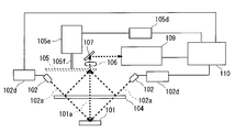
- the traveling direction of the light beam 102a Forms 45 ° with respect to the normal of the surface 101 of the sample.
- the reflected light 101 a traveling in the normal direction of the surface 101 of the sample is incident on the spectroscopic unit 109 through the objective lens 106 and the reflecting mirror 107.
- the spectral distribution of the reflected light 101 a is measured by the spectroscopic unit 109, and a signal indicating the measurement result is sent to the control processing unit 110.
- a glass plate 104 that is substantially orthogonal to the normal line of the sample surface 101 is provided between the white LED 102 and the sample surface 101.
- a diffusion plate chopper 105 that is intermittently inserted in an optical path through which the light beam 101a passes along a plane that is plane-symmetric with the surface 101 of the sample with respect to the glass plate 104 is provided.
- the diffuser plate chopper 105 has a diffuser blade 105a in the optical path through which the light beam 101a passes due to rotation around the rotation shaft 105f using the motor 105e under the control of the motor controller 105d. Is inserted intermittently.
- the diffuser blade 105a when the diffuser blade 105a is not inserted in the optical path through which the light beam 101a passes, the reflected light on the surface 101 of the sample enters the spectroscopic unit 109.
- the diffusing plate blade 105a when the diffusing plate blade 105a is inserted in the optical path through which the light beam 101a passes, a part of the light beam 102a is reflected on the surface of the glass plate 104 together with the reflected light on the surface 101 of the sample to the diffusing plate blade 105a. Incident. At this time, light that passes through the diffusion plate blade 105 a and is emitted in the normal direction of the upper surface of the diffusion plate blade 105 a enters the spectroscopic unit 109 through the objective lens 106 and the reflecting mirror 107.
- the control processing unit 110 the spectral distribution of the illumination light emitted from the white LED 102 is obtained based on the spectral distribution measured by the spectroscopic unit 109 when the diffusion plate blade 105a is inserted and not inserted.
- the measurement unit 210 of the spectral characteristic measuring device 230 is scanned along the color sample sheet 201 in which a plurality of color samples are arranged, The reflection characteristics are continuously measured.
- the measurement unit 210 is controlled by the drive circuit 206 so that the traveling direction of the illumination light emitted from the white LED 202 forms 45 ° with respect to the normal line of the surface 201 of the sample. Further, the color sample sheet 201 is illuminated by the illumination light.
- the reflected light traveling in the normal direction of the surface of the color sample sheet 201 out of the reflected light in the color sample sheet 201 is incident on the polychromator 204 through the objective lens 208.
- the spectral distribution information of the reflected light is obtained by the polychromator 204 and the signal processing circuit 207, and the spectral distribution information is sent to the control unit 205.
- the white LED 202 is driven by the drive circuit 206 with a constant current If.
- the drive circuit 206 includes a forward voltage detection circuit 206a.
- the forward voltage Vf in the white LED 202 when the spectral characteristics of each color sample are measured by the forward voltage detection circuit 206a is measured, and information indicating the forward voltage Vf is obtained. Is sent to the control unit 205.
- a white calibration plate 220 having a known spectral reflection characteristic is disposed at the start end of the scanning range of the measurement unit 210.
- the scanning unit 213, the conveyance control circuit 214, and the like are controlled by the control unit 205.
- the control unit 205 information indicating the spectral distribution of the reflected light of the white calibration plate 220 and the forward voltage Vf of the white LED 202 when measuring the spectral characteristics of each color sample is transmitted via the control unit 205 to the data processing device 240. Is output.
- the spectral distribution of the illumination light emitted from the white LED 202 varies depending on the temperature of the white LED 202. And there exists a relation peculiar to the element as shown in FIG. 23 between the forward voltage Vf in the white LED 202 driven by a constant current and the temperature of the white LED 202. For this reason, a fixed relationship can be established between the spectral distribution of the illumination light emitted from the white LED 202 and the forward voltage Vf.
- the spectral distribution and forward voltage Vf of the reflected light generated on the white calibration plate 220 measured before and after the scanning of the measurement unit 210 by the data processing device 240, the known spectral reflection characteristics, and the reflection generated in each color sample is estimated by interpolation using the forward voltage Vf as a parameter.
- a reference system having the optical system and the spectroscopic unit may not be provided.
- highly accurate measurement of the reflection characteristic of the sample can be realized by correcting the variation in the spectral distribution of the illumination light without complicating the reflection characteristic measurement device, increasing the manufacturing cost, and wasting resources. .
- the diffusion plate chopper 105 In the reflection characteristic measuring apparatus of Patent Document 1, assuming that the reflection characteristics of a plurality of samples are continuously measured, the diffusion plate chopper 105 must be intermittently inserted during measurement of each sample. It takes a long time.
- the white calibration plate 220 must be disposed at the start end of the scanning range of the measurement unit 210, resulting in an increase in the size of the system. Furthermore, it is not a dedicated system limited to an application in which the measurement unit 210 is scanned and the reflection characteristics of a plurality of color samples are continuously measured, and the system is too large when measuring the reflection characteristics of individual samples. And a problem that takes a long time for measurement.
- the present invention has been made in view of the above problems, and various aspects of the reflection characteristics of a sample can be measured quickly and accurately with a simple configuration regardless of fluctuations in the spectral distribution of illumination light.
- the purpose is to provide the technology to obtain.
- a reflection characteristic measuring apparatus includes a semiconductor light emitting element that emits illumination light by constant current driving, and a detection unit that detects a forward voltage of the semiconductor light emitting element. And the reflected light generated by reflecting the illumination light on the surface of the sample and the illumination light are mixed at a first ratio to output a first mixed light, and the reflected light and the illumination light are The mixing unit that outputs the second mixed light by mixing at a second ratio different from the first ratio, and the first reflected light and the illumination light that are generated when the illumination light is reflected from the surface of the first sample are mixed.
- the first spectral distribution of the first mixed light is measured by the first light reception of the first mixed light output by being mixed at the first ratio in the unit, and the first reflected light and the illumination light are In the mixing unit, the output is performed by mixing at the second ratio.
- a second spectral distribution of the second mixed light is measured by the second light reception of the mixed light, and the second reflected light and the illumination light generated by reflecting the illumination light on the surface of the second sample are the mixing unit.
- the third spectral distribution of the first mixed light is measured by the third light reception of the first mixed light output by being mixed at the first ratio, and the second reflected light and the illumination light are A measurement unit that measures a fourth spectral distribution related to the second mixed light by a fourth light reception of the second mixed light output by being mixed at the second ratio in the mixing unit, and detected by the detection unit
- a calculation unit that calculates a spectral reflectance coefficient of a third sample irradiated with the illumination light when a fifth forward voltage is applied to the semiconductor element, and the detection unit is configured by the measurement unit.
- the first of the semiconductor light emitting element is A voltage is detected, a second forward voltage of the semiconductor light emitting element is detected when the second light reception is performed by the measurement unit, and a second forward voltage of the semiconductor light emitting element is detected when the third light reception is performed by the measurement unit.
- a reflection characteristic measuring apparatus is the reflection characteristic measuring apparatus according to the first aspect, wherein the mixing unit includes a diffusion member including a diffusion unit that diffuses light, and the first to first Three samples are arranged in order between the position to be measured and the diffusing member, a part of the illumination light is reflected and incident on the diffusion part, and the remaining part of the illumination light is transmitted through the diffusion member.
- the first and second samples are provided with partial reflecting mirrors that irradiate the surfaces of the first and second samples arranged in order at the measurement position, and further, the state of the diffusing member is arranged in order at the measurement position. State change selectively set to a first state in which the diffusing unit is retracted from the optical path from the surface of the two samples to the measuring unit and a second state in which the diffusing unit is disposed on the optical path Part.
- a reflection characteristic measurement device is the reflection characteristic measurement device according to the second aspect, wherein the illumination unit is arranged on the surface of the first to third samples arranged in order at the measurement position. Irradiate the illumination light onto the surfaces of the first to third samples that are sequentially arranged at the measurement position along a virtual plane that is at an angle of 40 ° or more and 50 ° or less with respect to the normal.
- the measurement unit receives light reflected along the normal line on the surfaces of the first to third samples arranged in order at the measurement position in the illumination light, and the diffusion member is
- the first and second samples arranged in order at the measurement position with the first incident surface of the partial reflector on which the illumination light is incident as a reference. Are sequentially arranged at the surface to be measured and at the measurement position of the diffusing portion.
- the second incident surfaces facing the surfaces of the first and second samples have a plane symmetry relationship.
- a reflection characteristic measuring apparatus is the reflection characteristic measuring apparatus according to any one of the first to third aspects, wherein the linear function is the forward voltage Vf, and the spectral distribution of the illumination light.
- the calculation unit has an intensity at the wavelength ⁇ of the first spectral distribution I 1 ( ⁇ ), an intensity at the wavelength ⁇ of the second spectral distribution I 2 ( ⁇ ), and the first spectral distribution.
- the intensity at the wavelength ⁇ of the three spectral distributions is I 3 ( ⁇ ), the intensity at the wavelength ⁇ of the fourth spectral distribution is I 4 ( ⁇ ), and the reflection of the first sample with respect to the light with the wavelength ⁇ .
- the reflectance is R 1 ( ⁇ )
- the reflectance of the second sample with respect to light of the wavelength ⁇ is R 2 ( ⁇ )
- the first forward voltage is V f 1
- the second forward voltage is Vf 2
- the third forward voltage Vf 3
- the fourth forward voltage is Vf 4
- the coefficient unique to the wavelength ⁇ is a ⁇ , B ⁇ , c ⁇
- the reflection characteristic measuring apparatus is the reflection characteristic measuring apparatus according to the fourth aspect, wherein the measurement unit causes the third reflection to occur when the illumination light is reflected from the surface of the third sample. Measuring the fifth spectral distribution related to the first mixed light by the fifth light reception related to the first mixed light output by mixing the light and the illumination light at the first ratio in the mixing unit; The detection unit detects the fifth forward voltage of the semiconductor light emitting element when the measurement unit performs the fifth light reception, and the calculation unit detects the intensity at the wavelength ⁇ of the fifth spectral distribution.
- Is represented by I 5 ( ⁇ ) the fifth forward voltage is Vf 5
- the reflectance of the third sample with respect to light of the wavelength ⁇ is represented by R 3 ( ⁇ )
- the spectral reflectance coefficient is calculated by obtaining the reflectance R 3 ( ⁇ ) for each wavelength ⁇ .
- the reflection characteristic measurement apparatus is the reflection characteristic measurement apparatus according to the fourth or fifth aspect, wherein the measurement unit continuously measures the spectral distributions related to the reflected light of the plurality of samples.
- the first sample is a sample whose spectral distribution is first measured by the measurement unit of the plurality of samples, and the second sample is finally spectrally analyzed by the measurement unit of the plurality of samples. The sample whose distribution is to be measured.
- a reflection characteristic measurement device is the reflection characteristic measurement device according to any one of the fourth to sixth aspects, wherein the measurement unit maintains radiation of the illumination light by the semiconductor light emitting element.
- the illumination light is irradiated to the first reference sample whose reflectance with respect to the light of the wavelength ⁇ is R W ( ⁇ ) in a period in which the forward voltage of the semiconductor light emitting element becomes a constant voltage with time.
- the reflected light generated when the illumination light is reflected by the surface of the first reference sample and the illumination light are output by being mixed at the first ratio in the mixing unit.
- the first reference spectral distribution is measured by receiving the mixed light, and the reflected light generated when the illumination light is reflected by the surface of the first reference sample and the illumination light are the second ratio in the mixing unit. 2nd output by mixing with The second reference spectral distribution by receiving the focus light to measure, when the illumination light reflectance in the second reference sample is a R d ( ⁇ ) for light of the wavelength lambda is irradiated, the illumination
- the first mixed light is received.
- the three-spectral spectral distribution is measured, and the reflected light generated when the illumination light is reflected by the surface of the second reference sample and the illumination light are mixed and mixed at the second ratio in the mixing unit.
- a fourth reference spectral distribution is measured by receiving the second mixed light, and the calculation unit has an intensity at the wavelength ⁇ of the first reference spectral distribution I 1W ( ⁇ ), and the second reference spectral distribution.
- the intensity at the wavelength ⁇ is I 2W ( ⁇ )
- the third group The intensity at the wavelength ⁇ of the quasi-spectral distribution is I 1d ( ⁇ )
- the intensity at the wavelength ⁇ of the fourth reference spectral distribution is I 2d ( ⁇ )
- the forward voltage of the semiconductor light emitting element is the constant voltage.
- a reflection characteristic measurement device is the reflection characteristic measurement device according to any one of the first to seventh aspects, wherein the measurement unit reflects the illumination light on the surface of one sample.
- the sixth spectral distribution is measured by the sixth light reception of the second mixed light output by mixing the reflected light and the illumination light generated in step 2 with the second ratio in the mixing unit, and the illumination light is
- the seventh spectral distribution is measured by the seventh light reception of the first mixed light output by mixing the reflected light generated by reflecting on the surface of the sample and the illumination light at the first ratio in the mixing unit.
- the first mixed light or the illumination light that is output when the reflected light and the illumination light generated by reflecting the illumination light on the surface of the one sample are mixed at the second ratio in the mixing unit.
- the eighth spectral distribution is measured by the eighth light reception of the second mixed light that is output by mixing the reflected light and the illumination light generated at the second ratio in the mixing unit, and the detection unit
- a sixth forward voltage of the semiconductor light emitting element is detected when the sixth light reception is performed by the measurement unit, and a seventh forward voltage of the semiconductor light emitting element is detected when the seventh light reception is performed by the measurement unit.
- the eighth forward voltage of the semiconductor light emitting element is detected when the eighth light reception is performed by the measurement unit, and the arithmetic unit is approximately indicated by the sixth forward voltage, a coefficient, and a constant.
- the seventh forward voltage approximately indicated by the first relational expression showing the relationship between the spectral distribution of the illumination light and the sixth spectral distribution at the time of detection of the six forward voltages, the seventh forward voltage, the coefficient, and the constant.
- the second relational expression showing the relation between the seventh spectral distribution and the spectral distribution of the illumination light at the time of detection of the eighth forward voltage approximately indicated by the eighth forward voltage, a coefficient and a constant, and Based on the third relational expression indicating the relationship with the eighth spectral distribution, the spectral reflectance coefficient of the one sample is calculated.
- a reflection characteristic measurement apparatus is the reflection characteristic measurement apparatus according to the eighth aspect, wherein the measurement unit measures the sixth spectral distribution by the sixth light reception for the one sample, A first measurement operation in which the measurement of the seventh spectral distribution by the seventh light reception and the measurement of the eighth spectral distribution by the eighth light reception are performed in this order, or the measurement of the seventh spectral distribution by the seventh light reception And a second measurement operation in which the measurement of the sixth spectral distribution by the sixth light reception and the measurement of the eighth spectral distribution by the eighth light reception are performed in this order.
- a reflection characteristic measurement device is the reflection characteristic measurement device according to the ninth aspect, wherein the calculation unit is configured to execute the first measurement operation by the measurement unit. If the difference between the 6th forward voltage and the 8th forward voltage is less than or equal to the threshold value, it is assumed that the spectral distribution of the illumination light at the time of detection of the 6th to 8th forward voltages is constant, A spectral reflectance coefficient of the one sample is calculated based on the distribution and the sixth or eighth spectral distribution, and the second measurement operation is executed by the measurement unit; If the difference from the eighth forward voltage is equal to or less than a threshold value, it is assumed that the spectral distribution of the illumination light at the time of detection of the sixth to eighth forward voltages is constant, and the sixth spectral distribution and the Based on 7 or 8 spectral distribution, Calculating a reflectance factor.
- the semiconductor light emitting element included in the illumination unit reflects the illumination light emitted by the constant current drive on the surface of the first sample, the first reflected light, and the illumination light.
- the first forward voltage of the semiconductor light emitting element is detected by the detection unit included in the illumination unit and the first forward voltage of the semiconductor light emitting element is detected by the measurement unit.
- the first measurement step of measuring the first spectral distribution related to the first mixed light by the first light reception related to the mixed light, and the first reflected light and the illumination light differ from the first ratio by the mixing unit.
- the second light reception of the second mixed light by the measurement unit The second A second measurement step of measuring a second spectral distribution related to the combined light; and the second reflected light and the illumination light generated by reflecting the illumination light on the surface of the second sample by the mixing unit.
- the detection unit detects the third forward voltage of the semiconductor light emitting element while generating the first mixed light by mixing at the first and the measurement unit to detect the first forward light by the third light reception related to the first mixed light.
- Step and said first Based on the fourth forward voltage and the first to fourth spectral distributions, a linear function approximately representing the spectral distribution of the illumination light having the forward voltage of the semiconductor light emitting element as an independent variable is derived, and the detection
- the estimated spectral distribution of the illumination light when the fifth forward voltage is detected by the detecting unit is calculated, and the estimated spectral distribution is used.
- a reflection characteristic measurement method is the reflection characteristic measurement method according to the eleventh aspect, wherein the first to fourth measurement steps are performed in this order, and the second measurement step is performed.
- the mixing unit converts the third reflected light and the illumination light, which are generated when the illumination light is reflected from the surface of the third sample, at the first ratio. While the first mixed light is generated by mixing, the fifth forward voltage of the semiconductor light emitting element is detected by the detection unit, and the first mixing is performed by the measurement unit and the fifth light reception related to the first mixed light. And a fifth measurement step for measuring a fifth spectral distribution related to light.
- the first and second mixed lights having different mixing ratios can be generated with a simple configuration that can suppress an increase in size of the apparatus and an increase in manufacturing cost.
- the reflection characteristic measuring apparatus since the light beam that approximates the light beam incident on the surface of the sample is incident on the diffusion part, the reflected light from the surface of the sample and the illumination light are easily mixed. Can be done.
- the spectral distributions of the first and second mixed lights having different mixing ratios for the two samples are measured, so that the spectral distribution of the illumination light is approximately shown.
- a linear function of voltage is derived. For this reason, even if the spectral distribution measurement for a plurality of samples is continuously performed at high speed, the spectral distribution of the illumination light at the time of measuring each sample can be estimated by the forward voltage detected at the time of measuring each sample. .
- the spectral reflectance coefficient of the third sample can be obtained by a simple calculation.
- the reflection characteristic measuring apparatus when performing continuous measurement on a plurality of samples, the spectral distributions of the first and second mixed lights for the first and last samples, and those Since a large difference may occur in the forward voltage corresponding to, the estimation accuracy of the spectral distribution of the illumination light during measurement of each sample can be improved. Further, for example, during continuous measurement, only the spectral distribution of the first mixed light is measured, thereby enabling higher-speed continuous measurement.
- the reflection characteristic measuring apparatus for example, after the forward voltage is stabilized by driving the semiconductor light emitting element at the time of manufacturing the apparatus, the first and second mixed lights are related to the two reference samples.
- the coefficients a ⁇ , b ⁇ , and c ⁇ that are specific to the reflection characteristic measuring apparatus and specific to the wavelength ⁇ can be easily obtained.
- the illumination light at the time of measurement can be measured without measurement using a reference sample.
- the spectral distribution can be estimated. Thereby, the reflection characteristic of the sample can be measured with high accuracy regardless of the fluctuation of the spectral distribution of the illumination light.
- the reflection characteristic of the sample can be measured with higher accuracy.
- the reflection characteristic measuring apparatus even when there is almost no change in the forward voltage, the reflection characteristic of the sample can be measured with high accuracy.
- the same effect as that of the reflection characteristic measuring apparatus according to the first aspect can be obtained by the reflection characteristic measuring method according to any of the eleventh and twelfth aspects.
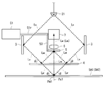
- FIG. 1 is a schematic diagram illustrating a schematic configuration of a reflection characteristic measuring apparatus according to an embodiment.
- FIG. 2 is a schematic diagram illustrating a schematic configuration of a reflection characteristic measuring apparatus according to an embodiment.
- FIG. 3 is a diagram illustrating an arrangement mode of a plurality of samples in the sample arrangement sheet.
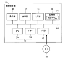
- FIG. 4 is a block diagram showing one configuration of the control calculation unit.
- FIG. 5 is a block diagram showing a functional configuration realized by the control calculation unit.
- FIG. 6 is a diagram for explaining a method of obtaining the coefficients a ⁇ , b ⁇ , and c ⁇ .
- FIG. 7 is a flowchart illustrating the operation flow of continuous measurement.
- FIG. 8 is a flowchart illustrating an operation flow of individual measurement.
- FIG. 7 is a flowchart illustrating the operation flow of continuous measurement.
- FIG. 9 is a flowchart showing an operation flow for obtaining the coefficients a ⁇ , b ⁇ , and c ⁇ .
- FIG. 10 is a flowchart showing an operation flow for obtaining the coefficients a ⁇ , b ⁇ , and c ⁇ .
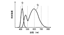
- FIG. 11 is a diagram illustrating spectral characteristics of illumination light according to two types of LEDs.
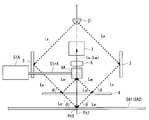
- FIG. 12 is a schematic diagram illustrating a schematic configuration of a reflection characteristic measuring apparatus according to a first modification.
- FIG. 13 is a schematic diagram illustrating a schematic configuration of a reflection characteristic measuring apparatus according to a first modification.
- FIG. 14 is a schematic diagram for explaining the configuration and operation of the diffusing member according to the first modification.
- FIG. 15 is a schematic diagram for explaining the configuration and operation of the diffusing member according to the first modification.
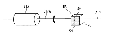
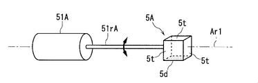
- FIG. 16 is a schematic view illustrating a part of a diffusing member according to a modification.
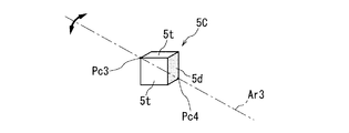
- FIG. 17 is a schematic view illustrating a part of the diffusing member according to a modification.
- FIG. 18 is a schematic view illustrating the configuration according to a modification.
- FIG. 19 is a schematic view illustrating the configuration of a reflection characteristic measuring apparatus according to Patent Document 1.
- FIG. 20 is a diagram illustrating the configuration of the diffusion plate chopper according to Patent Document 1.
- FIG. 21 is a schematic view illustrating the configuration of a spectral characteristic measurement system according to Patent Document 2.
- FIG. 22 is a schematic diagram showing a configuration of a white LED.
- FIG. 23 is a diagram illustrating the temperature dependence of the light emission characteristics of the white LED.
- FIG. 1 is a schematic diagram illustrating a schematic configuration of a reflection characteristic measuring apparatus 1 according to an embodiment.
- FIG. 2 is a diagram of the optical unit 40 and its periphery in the reflection characteristic measuring apparatus 1 as viewed from the right side of FIG. In FIG. 1 and FIG. 2, the optical path and the traveling direction related to the light flux are indicated by thick broken arrows.
- the reflection characteristic measuring apparatus 1 includes a measuring device 30 and a control calculation unit 10, and can measure the spectral reflectance coefficient of a sample placed at the measurement position Pm1. Specifically, in the reflection characteristic measuring apparatus 1, a plurality of samples Sm1 to Smn (n is an integer of 2 or more) having different reflection characteristics arranged on the sample arrangement sheet SA1 as shown in FIG. , The spectral reflectance coefficient of each sample Sm1 to Smn can be measured. In addition, the reflection characteristic measuring apparatus 1 can also measure the spectral reflectance coefficient of the individual sample SA2.
- the measuring instrument 30 includes an illumination unit 2, an optical unit 40, a spectroscope 9, and a drive control circuit 52.
- the illumination unit 2 includes a light source unit 21 and a light emission control circuit 22.
- the light source unit 21 is a light emitting element using a semiconductor (also referred to as a semiconductor light emitting element), and emits illumination light under the control of the light emission control circuit 22.
- the illumination light may be white light, for example, and the white light only needs to include a wide range of visible light in the wavelength band of 400 to 700 nm. That is, the light source unit 21 may be a white LED.
- Light emission control circuit 22 is a circuit for realizing the driving for emitting the illumination light L W from the light source unit 21 by supplying a constant current to the light source unit 21 (also referred to as constant current driving). Further, the light emission control circuit 22 detects a forward voltage Vf applied to the light source unit 21 when the illumination light LW is emitted from the light source unit 21 in accordance with the control of the control calculation unit 10. It has the composition as.
- the optical unit 40 includes a plurality of reflection units 3, partial reflection units 4, a light diffusion member 5, a lens unit 6, a reflection mirror 7, and a light guide unit 8.
- the plurality of reflecting portions 3 are arranged in an annular shape around an axis Px1 connecting the light source portion 21 and the measurement position Pm1.
- the distance between each reflecting portion 3 and the axis Px1 is substantially constant, and the plurality of reflecting portions 3 are arranged so as to be symmetric (also referred to as axial symmetry) with respect to the axis Px1.
- Each reflection part 3, may be a reflecting mirror for reflecting illumination light L W emitted from the light source unit 21.
- Partially reflecting portion 4 (an intermediate surface of the front and rear two surfaces, also referred to as a first entrance surface) incidence surface illumination light L W is incident of the illumination light L W of the reflected by the plurality of reflection portions 3 A portion (eg, about 10% of each wavelength component) is reflected, and the remaining portion (eg, about 90% of each wavelength component) is transmitted.
- the partially reflecting portion 4 is, for example, may be a glass plate, along with some is reflected to generate a reflected light L WR with the illumination light L W is irradiated by transmitting remaining portion Transmitted light LWT is generated.
- partially reflecting portion 4 is a mirror for branching the light of the illumination light L W into two rays of reflected light L WR and the transmitted light L WT (also referred to as partial reflection mirror). More specifically, the partially reflecting portion 4, each wavelength component of the illumination light L W is branched into a component of the transmitted light L WT and components of the reflected light L WR.
- Transmitted light L WT is irradiated onto the sample (also referred to as the measurement sample) disposed in measured position Pm1 among the samples Sm1 ⁇ Smn and sample SA2.
- the transmitted light LWT is irradiated onto the surface of the sample to be measured along a virtual plane that forms an angle ⁇ with respect to the surface of the sample to be measured, and reflected light is generated on the surface of the sample to be measured.
- the angle ⁇ may be about 45 °, for example.
- the reflected light generated here includes light (also referred to as sample reflected light) LRN that travels along the normal of the surface of the sample to be measured.
- the light source unit 21 (here, the axial Px1) normal to any surface of the measured sample emits illumination light L W in the direction of approximately 45 ° to.
- the illumination light LW is reflected by the plurality of reflecting portions 3 and transmitted along a second imaginary plane that is inclined by about 45 ° with respect to the normal of the surface of the sample to be measured (here, the axis Px1).
- L WT is irradiated on the surface of the sample to be measured, normal Px1 direction component L RN of reflected light generated in the sample to be measured is received via the lens 6 and the reflector 7.
- the illumination unit 2 and the optical unit 40 form a 45 ° c: 0 ° geometry recommended by various standards related to the measurement of the spectral characteristics of the printing surface.
- about 45 degrees should just be 40 degrees or more and 50 degrees or less.
- the light diffusing member 5 has a light diffusing portion that diffuses transmitted light in all directions.
- a light diffusing plate is employed as the light diffusing member 5
- substantially the entire surface of the light diffusing plate functions as a light diffusing portion.
- the light diffusing member 5 is fixed to, for example, a rod-shaped arm portion 53 that is connected substantially perpendicularly to the rotation shaft 51r of the rotation driving unit 51.
- the rotation drive unit 51 may be, for example, a rotary solenoid, and rotates the rotation shaft 51r under the control of the drive control circuit 52 according to the control signal from the control calculation unit 10.
- the rotation driving unit 51 can serve as a state changing unit that selectively sets the state of the light diffusing member 5 between the first state and the second state by the rotation of the rotating shaft 51r.
- the first state is a state in which the light diffusing unit is retracted from the optical path from the surface of the sample to be measured to the spectroscope 9 via the lens unit 6 and the reflecting mirror 7.
- the second state is a state in which the light diffusion member 5 is disposed on the optical path from the surface of the sample to be measured to the spectroscope 9 via the lens unit 6 and the reflecting mirror 7.
- the position of the outer edge of the light diffusing member 5 (also referred to as the retracted position) when the light diffusing member 5 is set to the first state is drawn with a solid line, and the light diffusing member 5 is set to the second state.
- the position of the outer edge of the light diffusing member 5 (also referred to as an intrusion position) is depicted by a broken line.
- the first incident surface of the partial reflection portion 4 is used as a reference, and the surface of the sample to be measured and the sample to be measured among the light diffusing members 5 are used.
- the surface (also referred to as a second incident surface) facing the surface of the surface has a plane symmetry relationship.
- the second incident surface, and the sample reflected light L RN generated at the surface of the measured sample, and the reflected light L WR caused by the first incident surface of the partially reflecting portion 4 is irradiated.
- the reflected light L WR irradiated to the light diffusing member 5 and the transmitted light L WT irradiated to the sample to be measured have the same incident angle and degree of convergence.
- the reflected light L WR irradiated to the light diffusing member 5 well represents the transmitted light L WT irradiated to the sample to be measured.
- the light beam which approximates the light flux incident on the surface of the measured sample is incident on the light diffusing member 5, is the portion of the sample reflected light L RN illumination light L W from the surface of the sample to be measured
- the reflected light LWR can be easily mixed.
- the first mixed light L M1 mainly including the sample reflected light LRN is incident on the lens unit 6.
- the light diffusing member 5 is set to the second state, the light diffusing member 5 is generated on the sample reflected light LRN generated on the surface of the sample to be measured and on the first incident surface of the partial reflecting portion 4.
- the second mixed light L M2 mainly mixed with the reflected light L WR is emitted to the lens unit 6.
- the first mixed light L M1 becomes light in which the sample reflected light L RN and the reflected light L WR that is part of the illumination light L W are mixed at the first ratio
- the second mixed light L M2 is the sample
- the reflected light L RN and the reflected light L WR that is a part of the illumination light L W are light mixed at a second ratio different from the first ratio.
- a partially reflecting portion 4 and the light diffusing member 5 and the rotary drive unit 51 serves as a mixing section where the first mixed light L M1 and the second mixed light L M2 selectively outputs.
- the partial reflection part 4, the light-diffusion member 5, and the rotation drive part 51 comprise a mixing part, the enlargement of the reflection characteristic measuring apparatus 1 and the increase in manufacturing cost will be suppressed, but a mixing ratio will differ.
- the first and second mixed lights L M1 and L M2 can be generated.
- the lens unit 6 converges the first mixed light L M1 and the second mixed light L M2 output from the mixing unit.
- the reflecting mirror 7 changes the direction of the light by totally reflecting the light emitted from the lens unit 6.
- the light guide 8 guides the convergent light reflected by the reflecting mirror 7 to the spectroscope 9.
- the light guide unit 8 may be an optical fiber, for example.
- the spectroscope 9 is a measurement unit that measures a spectral intensity distribution (hereinafter, abbreviated as a spectral distribution) of light guided by the light guide unit 8.
- the spectroscope 9 may be a polychromator or the like, for example.
- the spectroscope 9, when the light diffusing member 5 is set to the first state is mainly the first mixed light L M1 containing the sample reflected light L RN is received, the light diffusing member 5 to the second state If it is set, the second mixed light L M2 to the reflected light L WR and the sample reflected light L RN are mixed mainly is received.
- the control calculation unit 10 controls the entire reflection characteristic measuring apparatus 1. Further, the control calculation unit 10, to estimate the spectral distribution of the illumination light L W by the approximate function using the forward voltage Vf, regardless of variations in the spectral distribution of the illumination light L W, a simple structure, to be measured Measurement of reflection characteristics on the surface of the sample is performed quickly with high accuracy.
- FIG. 4 is a block diagram showing a configuration of the control calculation unit 10 included in the reflection characteristic measuring apparatus 1 according to the present embodiment.
- the control calculation unit 10 has a function of, for example, a personal computer (personal computer).
- the control calculation unit 10 includes an operation unit 11, a display unit 12, an interface (I / F) unit 13, a storage unit 14, an input / output (I / O) unit 15, and a control unit 16.
- the operation unit 11 includes, for example, a mouse and a keyboard.
- the display unit 12 includes, for example, a liquid crystal display.
- the I / F unit 13 is connected to the spectroscope 9, the light emission control circuit 22, and the drive control circuit 52 so as to be able to transmit and receive signals.
- the storage unit 14 has, for example, a hard disk or the like, and stores a program P1 and various information for realizing various operations in the control calculation unit 10.
- the I / O unit 15 includes, for example, a disk drive, can receive a storage medium 17 such as an optical disk, and can exchange data with the control unit 16.
- the control unit 16 includes a CPU 16a that functions as a processor and a memory 16b that can temporarily store information, and controls each unit of the control calculation unit 10. Further, in the control unit 16, various functions, various information processing, and the like are realized by reading and executing the program P1 in the storage unit 14. Data temporarily generated in this information processing is appropriately stored in the memory 16b or the like. Note that the control unit 16 can store the program stored in the storage medium 17 in the storage unit 14 or the like via the I / O unit 15.
- FIG. 5 is a block diagram illustrating a functional configuration related to the measurement of reflection characteristics realized by the control calculation unit 10.
- the functional configuration includes a coefficient calculation unit 161, an approximate function derivation unit 162, a spectral distribution estimation unit 163, a spectral reflectance coefficient calculation unit 164, a drive control unit 165, a lighting control unit 166, and a voltage detection control unit 167. included. With these functional configurations, the measurement of reflection characteristics related to the surface of the sample described below is realized.
- the reflection characteristic measuring apparatus 1 when the spectral reflectance coefficient of each sample Sm1 to Smn is measured while a plurality of samples Sm1 to Smn are scanned by the measuring device 30, for example, the spectral reflectance coefficient in the order of the samples Sm1 to Smn. Are measured continuously.
- the light diffusing member 5 Prior to the start of this continuous measurement (also referred to as continuous measurement), the light diffusing member 5 is set to the second state in which it is disposed at the entry position.
- the wavelength of light is represented by the symbol ⁇ .
- a sample Sm1 having a spectral reflectance coefficient R 1 ( ⁇ ) is placed at the measurement position Pm1. Then, according to the control signal from the lighting control unit 166 included in the control calculation unit 10, the light source unit 21 is turned on by constant current driving under the control of the light emission control circuit 22. At this time, in a state where the light diffusing member 5 is set to the second state, by the spectroscope 9, second mixed light L M2 according to the sample Sm1 is received, the spectral distribution I according to the second mixed light L M2 2-1 ( ⁇ ) is measured.
- the forward voltage Vf 2-1 second mixed light L M2 according to the sample Sm1 spectroscopically 9 is applied to the light source unit 21 when it is received is detected by the light emission control circuit 22, that order voltage Vf 2 Information indicating ⁇ 1 is sent to the control calculation unit 10.
- the detection of each forward voltage Vf by the light emission control circuit 22 is performed according to the control of the voltage detection control unit 167.
- the light diffusion member 5 is moved to the retracted position under the control of the drive control circuit 52 in accordance with a control signal from the drive control unit 165 included in the control calculation unit 10. Then, with the light diffusing member 5 set to the first state, the spectroscope 9 receives the first mixed light L M1 related to the sample Sm1, and the spectral distribution I 1 ⁇ related to the first mixed light L M1. 1 ( ⁇ ) is measured.
- the spectroscope 9 receives the first mixed light L M1 related to the sample Sm1
- the forward voltage Vf 1-1 applied to the light source unit 21 is measured by the light emission control circuit 22, and the forward voltage Vf is measured.
- Information indicating 1-1 is sent to the control calculation unit 10.
- M1 is sequentially received, and the spectral distribution I 1-i ( ⁇ ) related to the first mixed light L M1 is measured in order.
- the information is measured and information indicating each forward voltage Vf 1-i is sent to the control calculation unit 10.
- the light diffusion member 5 is moved to the intrusion position by the control of the drive control circuit 52 in accordance with a control signal from the drive control unit 165 included in the control calculation unit 10. Then, in a state where the light diffusing member 5 is set to the second state, by the spectroscope 9, second mixed light L M2 according to the sample Smn is received, the spectral distribution I 2 according to the second mixed light L M2 -N ( ⁇ ) is measured.
- the forward voltage Vf 2-n in which the second mixed light L M2 according to the sample Smn is applied to the light source unit 21 when it is received is determined by the light emission control circuit 22 by the spectroscope 9, that order voltage Vf 2 information indicating -n is sent to the control arithmetic unit 10.
- the light source unit 21 is turned off under the control of the light emission control circuit 22 in accordance with a control signal from the lighting control unit 166 included in the control calculation unit 10.
- the control calculation unit 10 calculates the spectral reflectance coefficients related to the samples Sm 1 to Smn.
- a method of calculating the spectral reflectance coefficient for each of the samples Sm1 to Smn will be described.
- I ( ⁇ ) p ⁇ ⁇ Vf + q ⁇ (1).
- I 1-1 ( ⁇ ) (p ⁇ ⁇ Vf 1-1 + q ⁇ ) ⁇ ⁇ R 1 ( ⁇ ) + a ⁇ ⁇ (2)
- I 2-1 ( ⁇ ) (p ⁇ ⁇ Vf 2-1 + q ⁇ ) ⁇ ⁇ b ⁇ ⁇ R 1 ( ⁇ ) + c ⁇ ⁇ (3)
- I 1-n ( ⁇ ) (p ⁇ ⁇ Vf 1-n + q ⁇ ) ⁇ ⁇ R n ( ⁇ ) + a ⁇ ⁇ (4)
- I 2-n ( ⁇ ) (p ⁇ ⁇ Vf 2-n + q ⁇ ) ⁇ ⁇ b ⁇ ⁇ R n ( ⁇ ) + c ⁇ ⁇ (5).
- the first parentheses in the right side of each equation in the equation (2) to (5) shows the intensity I (lambda) of the illumination light L W at each wavelength lambda.
- the first term including the spectral reflectance coefficients R 1 ( ⁇ ) and R n ( ⁇ ) The degree to which the illumination light L W contributes as the sample reflected light L RN to the distributions I 1-1 ( ⁇ ), I 2-1 ( ⁇ ), I 1-n ( ⁇ ), and I 2-n ( ⁇ ). Show.
- the second term includes the spectral distributions I 1-1 ( ⁇ ), I 2-1 ( ⁇ ), I 1-n ( ⁇ ), I 2-n (The degree to which the illumination light L W contributes as the reflected light L WR with respect to ⁇ ).
- Illumination light L W degree contributes as degree of contribution and the illumination light L W reflected light L WR as a sample reflected light L RN is disposed in the case and a retracted position where the light diffusing member 5 is disposed for entry position It differs depending on the case.
- the coefficients illumination light L W determines the degree contributes as a sample reflected light L RN is the one, as the illumination light L W reflected light L WR
- the coefficient for each wavelength ⁇ that determines the degree of contribution is a ⁇ .
- the coefficient of each wavelength lambda of the illumination light L W determines the degree contributes as a sample reflected light L RN is a b lambda
- the illumination light L W is reflected
- the coefficient for each wavelength ⁇ that determines the degree of contribution as the light L WR is c ⁇ .
- the wavelength dependence of the coefficients a ⁇ and c ⁇ is very small.
- the inherent coefficient information 142 is stored in the storage unit 14.
- the spectral distributions I 1-1 ( ⁇ ), I 2-1 ( ⁇ ), I 1-n ( ⁇ ), I 2-n ( ⁇ ), and the forward voltage Vf 1 ⁇ 1 , Vf 2 ⁇ 1 , Vf 1 ⁇ n , Vf 2 ⁇ n are obtained by actual measurement.
- the equations (2) to (5) are simultaneous for each wavelength ⁇ , with the coefficient p ⁇ , the constant q ⁇ , and the reflectance coefficients R 1 ( ⁇ ) and R n ( ⁇ ) as unknowns. It can be solved as an equation.
- the approximate function deriving unit 162 reads out information related to the equations (2) to (5) from the relational expression information 141 stored in the storage unit 14 and stores it in the storage unit 14. Information indicating the coefficients a ⁇ , b ⁇ , and c ⁇ is read from the intrinsic coefficient information 142. Next, the approximate function deriving unit 162 calculates the coefficients a ⁇ , b ⁇ , c ⁇ , and the spectral distributions I 1-1 ( ⁇ ), I 2-1 ( ⁇ ), I 1-n ( ⁇ ), I 2-n ( ⁇ ), and forward voltages Vf 1-1 , Vf 2-1 , Vf 1-n , Vf 2-n are applied to the equations (2) to (5). Then, the approximation function deriving unit 162 solves the equations (2) to (5) for each wavelength ⁇ , whereby the coefficient p ⁇ and the constant q ⁇ can be calculated.
- the coefficient p ⁇ and the constant q ⁇ are determined by the spectral distribution of the first and second mixed lights L M1 and L M2 measured for a small number of samples and the forward voltage Vf of the light source unit 21 at the time of light reception. Can be determined and an approximate function can be easily derived.
- I 1-i ( ⁇ ) (p ⁇ ⁇ Vf 1 ⁇ i + q ⁇ ) ⁇ ⁇ R i ( ⁇ ) + a ⁇ ⁇ (6)
- first portion in parentheses of the right side of (6) is a portion corresponding to the approximation function of Equation (1)
- the distribution is shown approximately.
- the coefficient p ⁇ and the constant q ⁇ calculated by the approximate function deriving unit 162 are known.
- the spectral distribution estimation unit 163 reads, for example, information related to the expression (6) from the relational expression information 141, and applies the coefficient p ⁇ , constant q ⁇ , and forward voltage Vf 1-i obtained by actual measurement and calculation. doing, it calculates the estimated spectral distribution of the illumination light L W during the detection of the forward voltage Vf 1-i.
- the spectral reflectance coefficients R 1 ( ⁇ ) and R n ( ⁇ ) of the samples Sm1 and Smn are solved by the spectral reflectance coefficient calculation unit 164 for each wavelength ⁇ , using Equations (2) to (5). It may be calculated by Information indicating the spectral reflectance coefficients R 1 ( ⁇ ) to R n ( ⁇ ) of the samples Sm1 to Smn calculated here is stored in the calculation result information 144 in the storage unit 14.
- the first and second mixed lights L M1 and L M having different mixing ratios for two samples Sm1 and Smn out of the plurality of samples Sm1 to Smn.
- the spectral distribution of M2 is measured.
- spectral distribution of the illumination light L W during measurement of each sample Smi can be estimated. Then, the spectral reflectance coefficient R i ( ⁇ ) of each sample Smi can be obtained by a simple calculation using the estimated spectral distribution.
- the spectral distributions I 1-1 ( ⁇ ), I 2-1 ( ⁇ ), I 1-n ( ⁇ ) of the first and second mixed lights L M1 and L M2 for the first and last samples Sm1 and Smn. , I 2-n ( ⁇ ), and forward voltages Vf 1-1 ( ⁇ ), Vf 2-1 ( ⁇ ), Vf 1-n ( ⁇ ), and Vf 2-n ( ⁇ ) corresponding thereto, Large differences can occur. For this reason, the independence of the equations (2) to (5) is secured. As a result, can estimate the accuracy of the spectral distribution of the illumination light L W is increased at the time of measurement of each sample Smi (i 1 ⁇ n) targeted.
- the spectral reflectance coefficient measurement (also referred to as individual measurement) for the individual sample SA2 in the reflection characteristic measuring apparatus 1 is based on the above-described continuous measurement for the plurality of samples Sm1 to Smn, and the number of samples n. May be changed to 1.
- the spectral reflectance coefficient R n ( ⁇ ) becomes the spectral reflectance coefficient R 1 ( ⁇ ), the expressions (2) and (4) match, and the individual samples SA2 and Sm1 match.
- the light diffusing member 5 is sequentially set to the second state, the first state, and the second state.
- the second mixed light L M2 when the light diffusing member 5 is set to the second state, by the spectroscope 9, second mixed light L M2 according to the individual sample SA2 is received, the second mixed light L M2
- the spectral distribution I 2-1 ( ⁇ ) is measured.
- first mixed light L M1 according to individual sample SA2 is received, according to the first mixed light L M1 Spectroscopy
- the distribution I 1-1 ( ⁇ ) is measured.
- the spectrometer during the first reception of the second mixed light L M2 according to the individual specimen SmA by 9, the forward voltage is applied to the light source unit 21 by the light emission control circuit 22 Vf 2 ⁇ 1 is detected, and information indicating the forward voltage Vf 2-1 is sent to the control calculation unit 10.
- the spectroscope 9 receives the first mixed light L M1 related to the individual sample SmA, the forward voltage Vf 1-1 applied to the light source unit 21 is detected by the light emission control circuit 22, and the forward voltage Vf is detected.
- Information indicating 1-1 is sent to the control calculation unit 10.
- the forward voltage Vf 2-1-2 being applied to the light source unit 21 is detected by the light emission control circuit 22, Information indicating the forward voltage Vf 2-1-2 is sent to the control calculation unit 10.
- the spectral distribution I 2-1 ( ⁇ ) is approximately expressed by Expression (3) using the forward voltage Vf 2-1 and the linear function expressed by Expression (1).
- the spectral distribution I 1-1 ( ⁇ ) is approximately expressed by Expression (2) using the forward voltage Vf 1-1 and the linear function expressed by Expression (1).
- the spectral distribution I 2-1-2 (lambda) is the forward voltage Vf 2-1-2 (lambda) and with and are used a linear function represented by the formula (1), wherein in place of Equation (5) ( It is shown approximately by 7).
- I 2-1-2 ( ⁇ ) (p ⁇ ⁇ Vf 2-1-2 + q ⁇ ) ⁇ ⁇ b ⁇ ⁇ R 1 ( ⁇ ) + c ⁇ ⁇ (7).
- Equation (2) in one eye expressions in parentheses on the right side, the spectral distribution I of the illumination light L W at the time when the forward voltage Vf 1-1 is detected (lambda), the forward voltage Vf 1 It is approximately shown by ⁇ 1 , a coefficient p ⁇ and a constant q ⁇ .
- Equation (2) is a first relational expression showing the relationship between the spectral distribution I of the illumination light L W and (lambda) and the spectral distribution I 1-1 (lambda).
- Equation (3) in first expression in parentheses on the right side, the spectral distribution I of the illumination light L W at the time when the forward voltage Vf 2-1 is detected (lambda), the forward voltage Vf 2- It is approximately represented by 1 and the coefficient p lambda a constant q lambda. That equation (3) is a second relational expression showing the relationship between the spectral distribution I of the illumination light L W and (lambda) and the spectral distribution I 2-1 (lambda).
- equation (7) is a third relational expression showing the relationship between the spectral distribution I of the illumination light L W and (lambda) and the spectral distribution I 2-1-2 (lambda).
- the spectral distributions I 1-1 ( ⁇ ), I 2-1 ( ⁇ ), I 2-1-2 ( ⁇ ), and the forward voltage Vf 1 ⁇ 1 , Vf 2-1 , Vf 2-1-2 are obtained by actual measurement.
- the equations (2), (3), and (7) are expressed as simultaneous equations with three numerical values of the coefficient p ⁇ , the constant q ⁇ , and the reflectance coefficient R 1 ( ⁇ ) as unknowns for each wavelength ⁇ . It is possible to solve.
- the spectral reflectance coefficient calculation unit 164 reads information related to the equations (2), (3), and (7) from the relational expression information 141 in the storage unit 14. Then, information indicating the coefficients a ⁇ , b ⁇ , and c ⁇ is read from the specific coefficient information 142 in the storage unit 14. Next, the spectral distributions I 1-1 ( ⁇ ), I 2-1 ( ⁇ ), I 2-1-2 ( ⁇ ) and the forward voltage Vf 1-1 obtained by the spectral reflectance coefficient calculation unit 164 are measured. , Vf 2-1 , Vf 2-1-2 , and coefficients a ⁇ , b ⁇ , and c ⁇ are applied to equations (2), (3), and (7).
- the spectral reflectance coefficient calculation unit 164 solves the equations (2), (3), and (7) for each wavelength ⁇ , thereby calculating the spectral reflectance coefficient R 1 ( ⁇ ) of the sample SmA. . That is, the spectral reflectance coefficient R 1 ( ⁇ ) of the sample SmA is calculated based on the first to third relational expressions expressed by the expressions (2), (3), and (7). Information indicating the spectral reflectance coefficient R 1 ( ⁇ ) of the sample SmA calculated here is stored in the calculation result information 144 in the storage unit 14.
- the spectral distribution of the illumination light L W during measurement of individual sample SA2 can be estimated.
- reflection characteristics of the individual sample SA2 can be measured easily with high accuracy.
- the spectral distribution I 2-1 ( ⁇ ), I 1-1 ( ⁇ ), I 2-1-2 ( ⁇ ) measurement and forward voltage Vf 2-1 , Vf 1-1 , Vf 2-1-2 are detected.
- the mode of three times of measurement and three times of detection is not limited to this.
- the light diffusing member 5 the first state is set the second state, and in this order in the second state, when the light diffusing member 5 is set in each state, the spectral distribution I 1-1 (lambda), I 2-1 ( ⁇ ), I 2-1-2 ( ⁇ ) may be measured, and the forward voltages Vf 1-1 , Vf 2-1 , Vf 2-1-2 may be detected.
- the spectral distribution I 2-1 ( ⁇ ), I 2-1-2 ( ⁇ ), I 1-1 ( ⁇ ) may be measured, and the forward voltages Vf 2-1 , Vf 2-1-2 , and Vf 1-1 may be detected.
- the light diffusing member 5 if it is followed by set twice to the second state, a forward voltage Vf 2-1 that the light diffusing member 5 is detected when it is set to 1 time to the second state, The difference from the forward voltage Vf 2-1-2 detected when the light diffusing member 5 is set to the second state for the second time can be reduced. Therefore, if the light diffusing member 5 is not set twice following the second state, the independence of the expressions (2), (3), and (7) is further secured, and the spectral reflectance coefficient R 1 ( ⁇ ) The calculation accuracy of can be improved.
- the spectroscope 9 causes the spectral distribution I 1-1 to be set. ( ⁇ ), I 2-1 ( ⁇ ), I 1-1-2 ( ⁇ ) is measured, the forward voltage Vf 1-1 in emission control circuit 22, Vf 2-1, Vf 1-1-2 detection May be.
- Equation (7-1) uses the forward voltage Vf 1-1-2 ( ⁇ ) and the linear function represented by Equation (1) to approximate the spectral distribution I 1-1-2 ( ⁇ ). It is a formula which shows.
- I 1-1-2 ( ⁇ ) (p ⁇ ⁇ Vf 1-1-2 + q ⁇ ) ⁇ ⁇ R 1 ( ⁇ ) + a ⁇ ⁇ (7-1).
- the spectral reflectance coefficient R 1 (( 1 )) is solved by solving the equations (2), (3), and (7-1) for each wavelength ⁇ by the spectral reflectance coefficient calculation unit 164.
- ⁇ can be calculated. That is, the spectral reflectance coefficient calculation unit 164 performs spectral distributions I 1-1 ( ⁇ ), I 2-1 ( ⁇ ), I 1-1-2 ( ⁇ ) and forward voltages Vf 1-1 ( ⁇ ), Vf. Based on the three relational expressions (2), (3), and (7-1) to which 2-1 ( ⁇ ) and Vf 1-1-2 ( ⁇ ) are applied, the spectral reflectance coefficient R of the sample SmA 1 ( ⁇ ) is calculated.
- the spectral distribution I 2-1 ( ⁇ ), I 1-1 ( ⁇ ), is measured I 1-1-2 (lambda) is the forward voltage Vf 2-1, Vf 1-1, Vf 1-1-2 may be detected.
- the spectral distribution I 1-1 ( ⁇ ), I 1-1-2 ( ⁇ ), I 2-1 ( ⁇ ) may be measured, and the forward voltages Vf 1-1 , Vf 1-1-2 , Vf 2-1 may be detected.
- the light diffusing member 5 is set twice after the first state, the forward voltage Vf 1-1 detected when the light diffusing member 5 is set to the first state for the first time; The difference from the forward voltage Vf 1-1-2 detected when the light diffusing member 5 is set to the first state for the second time can be reduced.
- the light diffusing member 5 is to be set twice in succession to the first state, the equation (2), (3), is more secured independence of (7-1), the spectral reflectance factor R 1 ( The calculation accuracy of ⁇ ) can be improved.
- the forward voltage Vf 1 ⁇ detected when the light diffusion member 5 is set in the order of the first state, the second state, and the first state. 1 , Vf 2-1 , Vf 1-1-2 may be almost the same.
- the forward voltage Vf 1-1 detected when the light diffusing member 5 is set to the first state for the first time and the light diffusing member 5 is set to the second state for the first time.
- the difference from the forward voltage Vf 1-1-2 detected at this time may be equal to or less than a predetermined threshold value Vt.
- the spectral distribution of the illumination light L W at the time of detection of the forward voltage Vf 1-1 until the detection of the forward voltage Vf 1-1-2 can be regarded as a constant.
- equation (2), (3) a function showing approximately the spectral distribution of the illumination light L W of the (p ⁇ ⁇ Vf 1-1 + q ⁇ ) and (p lambda ⁇ Vf 2- 1 + q ⁇ ) can be considered to exhibit a constant spectral distribution I 0 ( ⁇ ). That is, the equations (2) and (3) are obtained by replacing (p ⁇ ⁇ Vf 1-1 + q ⁇ ) and (p ⁇ ⁇ Vf 2-1 + q ⁇ ) with a constant spectral distribution I 0 ( ⁇ ). They may be (2-1) and (3-1).
- I 1-1 ( ⁇ ) I 0 ( ⁇ ) ⁇ ⁇ R 1 ( ⁇ ) + a ⁇ ⁇ (2-1)
- I 2-1 ( ⁇ ) I 0 ( ⁇ ) ⁇ ⁇ b ⁇ ⁇ R 1 ( ⁇ ) + c ⁇ ⁇ (3-1).
- Expressions (2-1) and (3-1) can be solved as simultaneous equations with the intensity I 0 ( ⁇ ) and the reflectance coefficient R 1 ( ⁇ ) as unknowns for each wavelength ⁇ . Therefore, in the control calculation unit 10, the spectral reflectance coefficient R 1 ( ⁇ ) is calculated by solving the equations (2-1) and (3-1) for each wavelength ⁇ by the spectral reflectance coefficient calculation unit 164. Can be done. That is, the spectral distribution I 1-1 (lambda), based on the I 2-1 (lambda), the spectral reflectance factor R 1 of the individual sample SA2 (lambda) can be calculated.
- Equations (3-2) and (7-2) are solved as simultaneous equations with the spectral distribution I 0 ( ⁇ ) and the spectral reflectance coefficient R 1 ( ⁇ ) as unknowns for each wavelength ⁇ .
- the coefficient R 1 ( ⁇ ) may be calculated. That is, the spectral reflectance coefficient R 1 ( ⁇ ) of the individual sample SA2 may be calculated based on the spectral distributions I 2-1 ( ⁇ ), I 1-1-2 ( ⁇ ).
- I 2-1 ( ⁇ ) I 0 ( ⁇ ) ⁇ ⁇ b ⁇ ⁇ R 1 ( ⁇ ) + c ⁇ ⁇ (3-2)
- I 1-1-2 ( ⁇ ) I 0 ( ⁇ ) ⁇ ⁇ R 1 ( ⁇ ) + a ⁇ ⁇ (7-2).
- the forward voltage Vf 2 ⁇ 2 detected when the light diffusing member 5 is set in the order of the second state, the first state, and the second state, respectively. 1 , Vf 1-1 , Vf 2-1-2 may be almost the same.
- the forward voltage Vf 2-1 detected when the light diffusing member 5 is set to the second state for the first time and the light diffusing member 5 is set to the second state for the second time.
- the difference between the forward voltage Vf 2-1-2 detected when it may be equal to or less than a predetermined threshold value Vt.
- the spectral distribution of the illumination light L W at the time of detection of the forward voltage Vf 2-1 until the detection of the forward voltage Vf 2-1-2 can be regarded as a constant.
- equation (2), (3) a function showing approximately the spectral distribution of the illumination light L W of the (p ⁇ ⁇ Vf 1-1 + q ⁇ ) and (p lambda ⁇ Vf 2- 1 + q ⁇ ) can be considered to exhibit a constant spectral distribution I 0 ( ⁇ ). That is, the equations (2) and (3) are obtained by replacing (p ⁇ ⁇ Vf 1-1 + q ⁇ ) and (p ⁇ ⁇ Vf 2-1 + q ⁇ ) with a constant spectral distribution I 0 ( ⁇ ). (2-3) and (3-3) may be used.
- I 1-1 ( ⁇ ) I 0 ( ⁇ ) ⁇ ⁇ R 1 ( ⁇ ) + a ⁇ ⁇ (2-3)
- I 2-1 ( ⁇ ) I 0 ( ⁇ ) ⁇ ⁇ b ⁇ ⁇ R 1 ( ⁇ ) + c ⁇ ⁇ (3-3).
- Expressions (2-3) and (3-3) can be solved as simultaneous equations with the intensity I 0 ( ⁇ ) and the reflectance coefficient R 1 ( ⁇ ) as unknowns for each wavelength ⁇ . Therefore, in the control calculation unit 10, the spectral reflectance coefficient R 1 ( ⁇ ) is calculated by solving the equations (2-3) and (3-3) for each wavelength ⁇ by the spectral reflectance coefficient calculation unit 164. Can be done. That is, the spectral reflectance coefficient R 1 ( ⁇ ) of the individual sample SA2 can be calculated based on the spectral distributions I 1-1 ( ⁇ ), I 2-1 ( ⁇ ).
- I 1-1 ( ⁇ ) I 0 ⁇ ⁇ R 1 ( ⁇ ) + a ⁇ ⁇ (2-4)
- I 2-1-2 ( ⁇ ) I 0 ⁇ ⁇ b ⁇ ⁇ R 1 ( ⁇ ) + c ⁇ ⁇ (7-4).
- the coefficients a ⁇ , b ⁇ , and c ⁇ can be obtained by the following method, for example, when the reflection characteristic measuring apparatus 1 is manufactured.
- a white plate or a white tile having a known spectral reflectance coefficient R W ( ⁇ ) is employed as the first reference sample, and light having a known spectral reflectance coefficient R d ( ⁇ ) as the second reference sample.
- a trap, a black plate, a black tile, or the like may be employed.
- the first and second reference samples may be achromatic samples having low wavelength dependency of the spectral reflectance coefficients R W ( ⁇ ) and R d ( ⁇ ), but the first reference sample and the second reference sample may be used. If the spectral reflectance coefficients R W ( ⁇ ) and R d ( ⁇ ) are significantly different from the sample, the calculation accuracy of the coefficients a ⁇ , b ⁇ , and c ⁇ can be improved.
- the forward voltage Vf applied to the light source unit 21 can be simply reduced with time.
- the light diffusing member 5 together with the second reference sample is placed in the measurement position Pm1 disposed in the insertion position, the second mixed light L M2 according to a second reference sample by the spectroscope 9 is received Assuming that In this case, the time T4, the spectral distribution I 2d of the second mixed light L M2 ( ⁇ ) is measured according to a second reference sample by spectroscopic 9, the forward voltage Vf 2d of the light source unit 21 by the light emission control circuit 22 is detected Is done.
- the first reference sample is disposed at the measurement position Pm1 and the light diffusion member 5 is disposed at the retracted position.
- the spectroscope 9 causes the first mixed light L related to the first reference sample to be measured. M1 is received.
- the spectroscope 9 measures the spectral distribution I 1W-1 ( ⁇ ) of the first mixed light L M1 related to the first reference sample, and the light emission control circuit 22 Thus, the forward voltage Vf 1W-1 of the light source unit 21 is detected.
- the spectroscope 9 measures the spectral distribution I 1W-2 ( ⁇ ) of the first mixed light L M1 related to the first reference sample, and the light emission control circuit 22 Thus, the forward voltage Vf 1W-2 of the light source unit 21 is detected.
- the first reference sample is arranged at the measurement position Pm1 and the light diffusion member 5 is arranged at the intrusion position.
- the spectroscope 9 causes the second mixed light L related to the first reference sample to be measured. M2 is received. Then, prior to the time of the time T4 (for example, time T2) in the spectral distribution I 2W-1 of the second mixed light L M2 ( ⁇ ) is measured according to the first reference sample by spectroscopic 9, the light emission control circuit 22 Thus, the forward voltage Vf 2W-1 of the light source unit 21 is detected.
- time after time T4 e.g., time T6
- time T4 e.g., time T6
- the forward voltage Vf 2W-2 of the light source unit 21 is detected.
- the second reference sample is arranged at the measurement position Pm1 and the light diffusing member 5 is arranged at the retracted position.
- the spectroscope 9 causes the first mixed light L related to the second reference sample to be measured. M1 is received.
- the spectroscope 9 measures the spectral distribution I 1d-1 ( ⁇ ) of the first mixed light L M1 related to the second reference sample, and the light emission control circuit 22 Thus, the forward voltage Vf 1d-1 of the light source unit 21 is detected.
- the spectroscope 9 measures the spectral distribution I 1d-2 ( ⁇ ) of the first mixed light L M1 related to the second reference sample, and the light emission control circuit 22 Thus, the forward voltage Vf 1d-2 of the light source unit 21 is detected.
- the forward voltage Vf 2d at time T4 is the reference forward voltage
- the spectral distribution I 1W of the first mixed light L M1 related to the first reference sample at times T1 and T5 before and after time T4. ⁇ 1 ( ⁇ ) and I 1W ⁇ 2 ( ⁇ ) are measured. Therefore, forward voltages Vf 1W ⁇ 1 , Vf 2d , Vf 1W ⁇ 2 at times T1, T4, T5 and spectral distributions I 1W-1 ( ⁇ ), I 1W-2 ( ⁇ ) at times T1, T5
- the spectral distribution I 1W ( ⁇ ) of the first mixed light L M1 related to the first reference sample at time T4 can be calculated by the linear approximation formula (8) based on the above.
- the spectral distribution I 1W ( ⁇ ) can be calculated by interpolation.
- This spectral distribution I 1W ( ⁇ ) is measured by the spectroscope 9 when the first reference sample is placed at the measurement position Pm1 and the light diffusion member 5 is placed at the retracted position at time T4. the spectral distribution of the first mixed light L M1 of the first reference sample to be predicted.
- I 1W ( ⁇ ) ⁇ I 1W ⁇ 1 ( ⁇ ) ⁇ (V 1W ⁇ 2 ⁇ Vf 2d ) + I 1W ⁇ 2 ( ⁇ ) ⁇ (Vf 2d ⁇ Vf 1W ⁇ 1 ) ⁇ / (Vf 1W ⁇ 2 ⁇ Vf 1W-1 ) (8).
- the spectral distribution I 2W-1 of the second mixed light L M2 according to a first reference sample ( ⁇ ), I 2W-2 ( ⁇ ) is measured. Therefore, forward voltages Vf 2W ⁇ 1 , Vf 2d , Vf 2W ⁇ 2 at times T2, T4, T6 and spectral distributions I 2W-1 ( ⁇ ), I 2W-2 ( ⁇ ) at times T2, T6 by linear approximation (9) based on the spectral distribution I 2W of the second mixed light L M2 according to a first reference sample at time T4 (lambda) can be calculated.
- the spectral distribution I 2W ( ⁇ ) can be calculated by interpolation.
- This spectral distribution I 2W ( ⁇ ) is measured by the spectroscope 9 when the first reference sample is disposed at the measurement position Pm1 and the light diffusion member 5 is disposed at the intrusion position at time T4. the spectral distribution of the second mixed light L M2 of the first reference sample to be predicted.
- I 2W ( ⁇ ) ⁇ I 2W-1 ( ⁇ ) ⁇ (V 2W ⁇ 2 ⁇ Vf 2d ) + I 2W ⁇ 2 ( ⁇ ) ⁇ (Vf 2d ⁇ Vf 2W ⁇ 1 ) ⁇ / (Vf 2W ⁇ 2 ⁇ Vf 2W-1 ) (9).
- the spectral distributions I 1d-1 ( ⁇ ) and I 1d-2 ( ⁇ ) of the first mixed light L M1 related to the second reference sample are measured. Therefore, forward voltages Vf 1d ⁇ 1 , Vf 2d , Vf 1d ⁇ 2 at times T 3, T 4, and T 7 and spectral distributions I 1d ⁇ 1 ( ⁇ ), I 1d ⁇ 2 ( ⁇ ) at times T 3, T 7 and
- the spectral distribution I 1d ( ⁇ ) of the first mixed light L M1 related to the second reference sample at time T4 can be calculated by the linear approximation formula (10) based on the above.
- the spectral distribution I 1d ( ⁇ ) can be calculated by interpolation.
- the spectral distribution I 1d ( ⁇ ) is measured by the spectroscope 9 when the second reference sample is placed at the measurement position Pm1 and the light diffusion member 5 is placed at the retracted position at time T4. the spectral distribution of the first mixed light L M1 of the second reference sample to be predicted.
- I 1d ( ⁇ ) ⁇ I 1d ⁇ 1 ( ⁇ ) ⁇ (V 1d ⁇ 2 ⁇ Vf 2d ) + I 1d ⁇ 2 ( ⁇ ) ⁇ (Vf 2d ⁇ Vf 1d ⁇ 1 ) ⁇ / (Vf 1d ⁇ 2 ⁇ Vf 1d-1 ) (10).
- the linear function represented by the equation (1) is used, and the forward voltage Vf 2d and the spectral reflectance coefficients R W and R d at the time T4 are further used.
- the spectral distributions I 1W ( ⁇ ), I 2W ( ⁇ ), I 1d ( ⁇ ), and I 2d ( ⁇ ) at time T4 are approximately expressed by equations (11) to (14).
- illumination light L W spectral distribution (p ⁇ ⁇ Vf 2d + q ⁇ ) constant spectral distribution I 0 of (lambda ) May be substituted.
- the coefficient calculation unit 161 calculates the spectral distributions I 1W ( ⁇ ), I 2W ( ⁇ ), and I 1d ( ⁇ ) based on the equations (8) to (10). Further, the coefficient calculation unit 161 reads the information of the four expressions (11) to (14) from the relational expression information 141 in the storage unit 14, and the spectral distribution I 1W ( ⁇ obtained by actual measurement and calculation in the four expressions. ), I 2W ( ⁇ ), I 1d ( ⁇ ), I 2d ( ⁇ ) are applied.
- the coefficients a ⁇ , b ⁇ , and c ⁇ can be calculated by solving the equations (11) to (14) for each wavelength ⁇ by the coefficient calculation unit 161.
- the specific coefficient information 142 indicating the calculated coefficients a ⁇ , b ⁇ , and c ⁇ is stored in the storage unit 14, for example.
- the spectral distribution I 2d ( ⁇ ) is obtained by actual measurement, but the present invention is not limited to this.
- the time T4 in spectral distribution I 2d (lambda) is not measured, before and after the time of the time T4, the spectral distribution I 2d-1 of the second mixed light L M2 according to a second reference sample (lambda), I 2d -2 ( ⁇ ) may be measured, and the spectral distribution I 2d ( ⁇ ) may be calculated by so-called interpolation calculation.
- the forward voltage Vf 2d at time T4 the spectral distribution I 2d-1 ( ⁇ ) and the forward voltage Vf 2d-1 at the time of measurement
- the spectral distribution I 2d-2 ( ⁇ ) forward when a measurement voltage of Vf 2d-2
- the spectral distribution I 2d ( ⁇ ) can be calculated by the linear approximation formula (15) based on the spectral distributions I 2d-1 ( ⁇ ) and I 2d-2 ( ⁇ ).
- I 2d ( ⁇ ) ⁇ I 2d ⁇ 1 ( ⁇ ) ⁇ (V 2d ⁇ 2 ⁇ Vf 2d ) + I 2d ⁇ 2 ( ⁇ ) ⁇ (Vf 2d ⁇ Vf 2d ⁇ 1 ) ⁇ / (Vf 2d ⁇ 2 ⁇ Vf 2d-1 ) (15).
- all of the spectral distributions I 1W ( ⁇ ), I 2W ( ⁇ ), I 1d ( ⁇ ), and I 2d ( ⁇ ) may be calculated by interpolation. Also, any one of the spectral distributions I 1W ( ⁇ ), I 2W ( ⁇ ), I 1d ( ⁇ ), and I 2d ( ⁇ ) is obtained by actual measurement, and the other spectral distributions are interpolated or extrapolated. It may be calculated by calculation.
- FIG. 7 is a flowchart illustrating the operation flow of continuous measurement in the reflection characteristic measuring apparatus 1.
- This operation flow can be executed under the control of the control calculation unit 10.
- this operation flow is started according to the operation of the operation unit 11 by the operator, and the process proceeds to step S1.
- movement flow is started, the light-diffusion member 5 is arrange
- step S1 the measuring device 30 is arranged on the top sample Sm1 in the sample arrangement sheet SA1 by the control calculation unit 10.
- step S2 the light source unit 21 is turned on by constant current driving under the control of the lighting control unit 166.
- step S3 the second mixed light L M2 is received according to the sample Sm1 spectroscopically 9, spectral distribution I 2-1 (lambda) is measured according to the second mixed light L M2. Further, the light emission control circuit 22, a second mixed light L M2 order is applied to the light source unit 21 when it is received voltage Vf 2-1 are measured according to the sample Sm1 spectroscopically 9. At this time, information indicating the spectral distribution I 2-1 ( ⁇ ) and the forward voltage Vf 2-1 is sent to the control calculation unit 10.
- step S4 the light diffusing member 5 is moved and placed at the retracted position under the control of the drive control unit 165.
- step S5 the control arithmetic unit 10 starts scanning the n samples Sm1 to Smn.
- step S6 the first mixed light L M1 according to the sample Sm1 ⁇ Smn is received sequentially by the spectroscope 9, spectral distribution I 1-1 according to the first mixed light L M1 ( ⁇ ) ⁇ I 1 -n ( ⁇ ) Are measured in order.
- the forward voltage Vf 1-1 to Vf 1-n applied to the light source unit 21 when the light emission control circuit 22 receives the first mixed light L M1 related to each of the samples Sm1 to Smn by the spectroscope 9. Are measured in order.
- the spectral distribution I 1-1 ( ⁇ ) ⁇ I 1 -n ( ⁇ ) and the information indicating the forward voltage Vf 1-1 ⁇ Vf 1-n are sent to the control arithmetic unit 10.
- step S7 the scanning of the n samples Sm1 to Smn is completed by the control arithmetic unit 10.
- step S8 the light diffusing member 5 is moved and placed at the entry position under the control of the drive control unit 165.
- step S9 the spectroscope 9 receives the second mixed light L M2 related to the sample Smn, and the spectral distribution I 2-n ( ⁇ ) related to the second mixed light L M2 is measured.
- the light emission control circuit 22 measures the forward voltage Vf 2-n applied to the light source unit 21 when the spectroscope 9 receives the second mixed light L M2 related to the sample Smn. At this time, information indicating the spectral distribution I 2-n ( ⁇ ) and the forward voltage Vf 2-n is sent to the control calculation unit 10.
- step S10 the light source unit 21 is turned off under the control of the lighting control unit 166.
- step S11 the approximate function deriving unit 162 derives an approximate function using the forward voltage Vf.
- the spectral distributions I 1-1 ( ⁇ ), I 2-1 ( ⁇ ), I 1-n ( ⁇ ), I 2-n obtained in steps S3, S6, and S9 by the approximate function deriving unit 162.
- ( ⁇ ) forward voltages Vf 1-1 ( ⁇ ), Vf 2-1 ( ⁇ ), Vf 1-n ( ⁇ ), Vf 2-n ( ⁇ ), and coefficients a ⁇ , b ⁇ , c ⁇ are 4 This applies to equations (2) to (5).
- the approximate function deriving unit 162 solves the equations (2) to (5) for each wavelength ⁇ , thereby calculating the coefficient p ⁇ and the constant q ⁇ .
- step S13 information indicating the spectral reflectance coefficients R 1 ( ⁇ ) to R n ( ⁇ ) of the samples Sm1 to Smn calculated in step S12 is calculated in the storage unit 14 by the spectral reflectance coefficient calculating unit 164.
- the result information 144 is stored.
- information indicating the spectral reflectance coefficients R 1 ( ⁇ ) to R n ( ⁇ ) may be visually output to the display unit 12.
- FIG. 8 is a flowchart illustrating an operation flow of individual measurement in the reflection characteristic measuring apparatus 1.
- This operation flow can be executed under the control of the control calculation unit 10.
- this operation flow is started in accordance with the operation of the operation unit 11 by the operator, and the process proceeds to step S21.
- the light-diffusion member 5 is arrange
- step S21 the measuring instrument 30 is placed on the individual sample SA2 by the operator, and the flow from step S22 is started by the operation of the operation unit 11.
- step S22 the light source unit 21 is turned on by constant current driving under the control of the lighting control unit 166.
- step S23 the second mixed light L M2 is received according to the individual sample SA2 spectroscopically 9, spectral distribution I 2-1 (lambda) is measured according to the second mixed light L M2. Further, the light emission control circuit 22, the forward voltage Vf 2-1 which is applied to the light source unit 21 is measured when the second mixed light L M2 according to the individual sample SA2 is received by the spectroscope 9. At this time, information indicating the spectral distribution I 2-1 ( ⁇ ) and the forward voltage Vf 2-1 is sent to the control calculation unit 10.
- step S24 the light diffusing member 5 is moved and placed at the retracted position under the control of the drive control unit 165.
- step S25 the spectroscope 9 receives the first mixed light L M1 related to the individual sample SA2, and the spectral distribution I 1-1 ( ⁇ ) related to the first mixed light L M1 is measured.
- the light emission control circuit 22 measures the forward voltage Vf 1-1 applied to the light source unit 21 when the spectroscope 9 receives the first mixed light L M1 related to the individual sample SA2. At this time, information indicating the spectral distribution I 1-1 ( ⁇ ) and the forward voltage Vf 1-1 is sent to the control calculation unit 10.
- step S26 the light diffusing member 5 is moved and placed at the intrusion position under the control of the drive control unit 165.
- step S27 the second mixed light L M2 is received again according to the individual sample SA2 spectroscopically 9, spectral distribution I 2-1-2 (lambda) is measured according to the second mixed light L M2. Further, the light emission control circuit 22, the forward voltage Vf 2-1-2 being applied to the light source unit 21 is measured when the second mixed light L M2 is received again according to the individual sample SA2 spectroscopically 9 The At this time, information indicating the spectral distribution I 2-1-2 ( ⁇ ) and the forward voltage Vf 2-1-2 is sent to the control calculation unit 10.
- step S28 the light source unit 21 is turned off under the control of the lighting control unit 166.
- step S29 the difference between the forward voltage Vf 2-1 detected in step S23 and the forward voltage Vf 2-1-2 detected in step S27 by the control calculation unit 10, that is, the amount of change in the forward voltage Vf is It is determined whether or not the threshold value Vt is exceeded. If the change amount of the forward voltage Vf exceeds the threshold value Vt, the process proceeds to step S30. If the change amount of the forward voltage Vf is equal to or less than the threshold value Vt, the process proceeds to step S31.
- the spectral reflectance coefficient calculation unit 164 calculates the spectral reflectance coefficient R 1 ( ⁇ ) of the individual sample SA2. Specifically, the spectral distributions I 2-1 ( ⁇ ), I 1-1 ( ⁇ ), I 2-1-2 ( ⁇ ) and the forward voltage Vf 2-1 obtained in steps S23, S25, and S27, Vf 1-1 , Vf 2-1-2 and coefficients a ⁇ , b ⁇ , and c ⁇ are applied to the three equations (2), (3), and (7), and for each wavelength ⁇ , the equation (2) , (3), (7) are solved. Thereby, the spectral reflectance coefficient R 1 ( ⁇ ) is calculated.
- step S31 the spectral reflectance coefficient calculation unit 164 calculates the spectral reflectance coefficient R 1 ( ⁇ ) of the individual sample SA2. Specifically, for example, equations (2-1) and (3-1) are solved for each wavelength ⁇ . Thereby, the spectral reflectance coefficient R 1 ( ⁇ ) is calculated.
- step S32 information indicating the spectral reflectance coefficient R 1 ( ⁇ ) of the individual sample SA2 calculated in step S30 or step S31 by the spectral reflectance coefficient calculating section 164 is calculated result information 144 in the storage section 14. Is remembered. At this time, information indicating the spectral reflectance coefficient R 1 ( ⁇ ) may be visually output to the display unit 12.
- FIG. 9 and FIG. 10 are flowcharts illustrating an operation flow relating to the determination of the coefficients a ⁇ , b ⁇ , and c ⁇ in the reflection characteristic measuring apparatus 1.
- This operation flow can be executed under the control of the control calculation unit 10. For example, this operation flow is started in accordance with the operation of the operation unit 11 by the operator, and the process proceeds to step S41.
- the light diffusing member 5 is disposed at the retracted position.
- step S41 the light source unit 21 is turned on by constant current driving under the control of the lighting control unit 166.
- step S42 the spectral reflectance factor R W ( ⁇ ) is the measuring instrument 30 is disposed to the white board as the first reference sample of known.
- step S43 the spectroscope 9 receives the first mixed light L M1 related to the white plate, and the spectral distribution I 1W-1 ( ⁇ ) related to the first mixed light L M1 is measured.
- the light emission control circuit 22 measures the forward voltage Vf 1W-1 applied to the light source unit 21 when the spectroscope 9 receives the first mixed light L M1 related to the white plate. At this time, information indicating the spectral distribution I 1W-1 ( ⁇ ) and the forward voltage Vf 1W-1 is sent to the control calculation unit 10.
- step S44 the light diffusing member 5 is moved and placed at the entry position under the control of the drive control unit 165.
- step S45 the second mixed light L M2 according to the white plate is received by the spectroscope 9, spectral distribution I 2W-1 ( ⁇ ) is measured according to the second mixed light L M2. Further, the light emission control circuit 22, the forward voltage Vf 2W-1 of the second mixed light L M2 according to the white plate is applied to the light source unit 21 when it is received is measured by the spectroscope 9. At this time, information indicating the spectral distribution I 2W-1 ( ⁇ ) and the forward voltage Vf 2W-1 is sent to the control calculation unit 10.
- step S46 the measuring device 30 is placed in an optical trap as a second reference sample whose spectral reflectance coefficient R d ( ⁇ ) is known.
- step S47 the light diffusing member 5 is moved and placed at the retracted position under the control of the drive control unit 165.
- step S48 the spectroscope 9 receives the first mixed light L M1 related to the optical trap, and the spectral distribution I 1d-1 ( ⁇ ) related to the first mixed light L M1 is measured.
- the light emission control circuit 22 measures the forward voltage Vf 1d-1 applied to the light source unit 21 when the spectroscope 9 receives the first mixed light L M1 related to the optical trap. At this time, information indicating the spectral distribution I 1d-1 ( ⁇ ) and the forward voltage Vf 1d-1 is sent to the control calculation unit 10.
- step S49 the light diffusing member 5 is moved and arranged at the entry position under the control of the drive control unit 165.
- step S50 the spectroscope 9 receives the second mixed light L M2 related to the optical trap, and the spectral distribution I 2d ( ⁇ ) related to the second mixed light L M2 is measured. Further, the light emission control circuit 22, the forward voltage Vf 2d of the second mixed light L M2 according to the light trap is applied to the light source unit 21 when it is received is measured by the spectroscope 9. At this time, information indicating the spectral distribution I 2d ( ⁇ ) and the forward voltage Vf 2d is sent to the control calculation unit 10.
- step S51 the measuring device 30 is placed on a white plate as a first reference sample whose spectral reflectance coefficient R W ( ⁇ ) is known.
- step S52 of FIG. 10 the light diffusing member 5 is moved and placed at the retracted position under the control of the drive control unit 165.
- step S53 the spectroscope 9 receives the first mixed light L M1 related to the white plate, and the spectral distribution I 1W-2 ( ⁇ ) related to the first mixed light L M1 is measured.
- the light emission control circuit 22 measures the forward voltage Vf 1W-2 applied to the light source unit 21 when the spectroscope 9 receives the first mixed light L M1 related to the white plate. At this time, information indicating the spectral distribution I 1W-2 ( ⁇ ) and the forward voltage Vf 1W-2 is sent to the control calculation unit 10.
- step S54 the light diffusing member 5 is moved and placed at the entry position under the control of the drive control unit 165.
- step S55 the second mixed light L M2 according to the white plate is received by the spectroscope 9, spectral distribution I 2W-2 ( ⁇ ) is measured according to the second mixed light L M2. Further, the light emission control circuit 22, the forward voltage Vf 2W-2 in which the second mixed light L M2 according to the white plate is applied to the light source unit 21 when it is received is measured by the spectroscope 9. At this time, information indicating the spectral distribution I 2W-2 ( ⁇ ) and the forward voltage Vf 2W-2 is sent to the control calculation unit 10.
- step S56 the measuring device 30 is placed in an optical trap as a second reference sample whose spectral reflectance coefficient R d ( ⁇ ) is known.
- step S57 the light diffusing member 5 is moved and placed at the retracted position under the control of the drive control unit 165.
- step S58 the spectroscope 9 receives the first mixed light L M1 related to the optical trap, and the spectral distribution I 1d-2 ( ⁇ ) related to the first mixed light L M1 is measured.
- the light emission control circuit 22 measures the forward voltage Vf 1d-2 applied to the light source unit 21 when the spectroscope 9 receives the first mixed light L M1 related to the optical trap. At this time, information indicating the spectral distribution I 1d-2 ( ⁇ ) and the forward voltage Vf 1d-2 is sent to the control calculation unit 10.
- step S59 the light source unit 21 is turned off under the control of the lighting control unit 166.
- step S60 the spectral distributions I 1W ( ⁇ ), I 2W ( ⁇ ), and I 1d ( ⁇ ) corresponding to the forward voltage Vf 2d as the reference forward voltage obtained in step S50 are calculated by the coefficient calculation unit 161 using the formula ( 1 ). It is calculated by the interpolation calculation based on 8) to (10).
- step S61 the coefficient calculation unit 161 calculates the coefficients a ⁇ , b ⁇ , and c ⁇ using the simultaneous equations of the four formulas (11) to (14).
- step S62 the coefficient calculation unit 161 stores the specific coefficient information 142 indicating the coefficients a ⁇ , b ⁇ , and c ⁇ calculated in step S61 in the storage unit 14.
- the light source unit 21 is caused major changes in the spectral distribution of the illumination light L W is emitted by the temperature rise immediately after the lighting, using the forward voltage Vf spectral distribution of the illumination light L W corresponding to the measurement of the sample is estimated by the function. Therefore, even if either of the continuous measurement and individual measurement, it is not necessary to measure the reference sample such white plate or the like to estimate the spectral distribution of the illumination light L W. Therefore, regardless of the spectral distribution change of the illumination light L W, with a simple configuration, measurement of the various aspects of the reflection characteristic of the sample can be quickly performed with high accuracy.
- the forward voltage Vf applied to the light source unit 21 over time is simply as shown in FIG.
- the method for obtaining the coefficients a ⁇ , b ⁇ , and c ⁇ has been shown, but the present invention is not limited to this.
- the spectroscope 9 measures the spectral distribution I 1W ( ⁇ ) of the first mixed light L M1 and the spectral distribution I 2W ( ⁇ ) of the second mixed light L M2 for the first reference sample, and the second reference.
- the coefficient calculation unit 161 reads the information of the four formulas (16) to (19) from the relational expression information 141 in the storage unit 14, and the spectral distribution I obtained by actual measurement in the four formulas. 1W ( ⁇ ), I 2W ( ⁇ ), I 1d ( ⁇ ), I 2d ( ⁇ ) and known spectral reflectance coefficients R W , R d are applied.
- the coefficients a ⁇ , b ⁇ , and c ⁇ can be calculated by solving the equations (16) to (19) for each wavelength ⁇ .
- the calculated coefficients a ⁇ , b ⁇ , and c ⁇ are stored in the storage unit 14 as the specific coefficient information 142, for example.
- the coefficient a lambda, b lambda, for measuring the number and amount of calculation for obtaining the c lambda is reduced, the coefficient a ⁇ , b ⁇ , c ⁇ can be obtained easily.
- a white LED is used as the light source unit 21.
- the present invention is not limited to this.
- a combination of two or more types of LEDs having different spectral distributions of emitted light is used. May be.
- a white LED that emits white light having a distribution of relative intensity with respect to the wavelength indicated by the curve CW in FIG. 11, and a relative intensity with respect to the wavelength indicated by the curve CP in FIG.
- a combination of violet LEDs that emit violet light having the following distribution may be employed. More specifically, for example, a white LED emits white light with blue light emission and yellow fluorescence excited by blue light emission, and a purple LED has a wavelength range of 400 to 450 nm where the white light has almost no intensity. An example of emitting violet light having intensity is given.
- the coefficients a ⁇ , b ⁇ , and c ⁇ for each LED may be obtained by measurement in which each LED is individually turned on by the same method as in the above embodiment.
- the coefficient p ⁇ the constant q ⁇ , and the spectrum for each LED are used.
- the reflectance coefficients R 1 ( ⁇ ) and R n ( ⁇ ) may be calculated.
- the spectral distribution I 1-i ( ⁇ ) of the first mixed light L M1 related to each sample Rmi measured while the two-color LEDs are turned on is applied to the left side of Equation (6), so that the wavelength ⁇
- the spectral reflectance coefficient R i ( ⁇ ) related to the sample Rmi can be calculated every time.
- the coefficient p ⁇ for each LED is obtained by measuring each LED individually for each sample RmA and using the equations (2), (3), and (7).
- the constant q ⁇ and the spectral reflectance coefficient R 1 ( ⁇ ) may be calculated.
- the estimated spectral distribution of each color light at the time of measurement of the sample RmA is calculated based on the formula (1), and the sum of the estimated spectral distributions of the respective color lights is the first on the right side of the formula (2).
- the spectral reflectance coefficient R 1 ( ⁇ ) of the individual sample RmA is calculated by applying the sum of the spectral distributions of the first mixed light L M1 by each color light to the left side of the formula (2). It should be done.
- the first sample Rm1 and the nth sample Rmn among the plurality of samples Rm1 to Rmn are targeted, and the light diffusion member 5 is disposed at the intrusion position.
- I 2-n ( ⁇ ) is measured, not limited to this.
- any two x-th and y-th samples Rmx and Rmy out of the plurality of samples Rm1 to Rmn are targeted.
- the spectral distributions I 2-x ( ⁇ ) and I 2-y ( ⁇ ) of the second mixed light L M1 may be measured while the light diffusing member 5 is disposed at the entry position.
- the spectral distributions I 1-1 ( ⁇ ) to I 1-n ( ⁇ ) of a plurality of samples Rm1 to Rmn are continuously measured at high speed, they are detected at the time of measuring each sample Rmi. that the forward voltage Vf 1-i by the spectral distribution of the illumination light L W during measurement of each sample Rmi I 1-1 ( ⁇ ) can be estimated.
- a diffusion plate is used as the light diffusing member 5.
- a polymer dispersed liquid crystal element (PDLC: Polymer Dispersed Liquid Crystal) may be employed as the light diffusion member 5.
- the polymer-dispersed liquid crystal element performs a function similar to that of a diffusion plate when the application of voltage is stopped, and functions like a glass capable of transmitting light when a voltage is applied. Therefore, when a polymer dispersion type liquid crystal element is employed as the light diffusing member 5, the rotation driving unit 51, the rotating shaft 51r, the rod-shaped arm portion 53, and the like for moving the light diffusing member 5 are not necessary. For this reason, size reduction of an apparatus and reduction of manufacturing cost can be achieved.
- substantially the entire light diffusing member 5 is configured by a diffusing plate, and the light diffusing member 5 is moved into the intrusion position and the retracted position by the rotation drive unit 51, the rotation shaft 51r, and the rod-shaped arm portion 53.
- a part of the light diffusing member 5 is composed of a light diffusing unit that diffuses light, and the spectroscope 9 is changed from the surface of the sample to be measured via the lens unit 6 and the reflecting mirror 7 by changing the posture of the light diffusing member 5. Even if the state of the light diffusing member is selectively set between the first state where the light diffusing part is retracted from the optical path leading to the second state where the light diffusing part is disposed on the optical path good.
- the light diffusing member 5 is replaced with the light diffusing member 5 ⁇ / b> A, and the rotation driving unit 51 and the rotating shaft are replaced.
- the reflection characteristic measuring apparatus 1A according to the first modification in which the 51r and the rod-shaped arm portion 53 are replaced with the rotation drive unit 51A and the rotation shaft 51rA may be employed. Note that, by these replacements, the measuring device 30 is replaced with the measuring device 30A.
- the light diffusing member 5A is fixed to, for example, the rotation shaft 51rA of the rotation drive unit 51A, as shown in FIGS.
- the rotation drive unit 51A may be, for example, a stepping motor or the like, and rotates the rotation shaft 51rA by the control by the drive control circuit 52 according to the control signal from the control calculation unit 10.
- the light diffusing member 5A is a transparent rectangular parallelepiped member, and passes through the center of two surfaces parallel to the extending direction of the optical path from the surface of the sample to be measured to the reflecting mirror 7 by the rotation driving unit 51A. It rotates about the axis Ar1.
- one of the four surfaces through which the axis Ar1 does not pass is a diffusion surface 5d, and the other three surfaces are smooth surfaces 5t.
- the diffusion surface 5d functions as a light diffusion unit that diffuses incident light.
- the light diffusion member 5A is rotated by ⁇ 90 °, and the first state where the smooth surface 5t faces the surface of the sample to be measured and the diffusion surface 5d It is selectively set to the opposing second state.
- FIG. 14 shows a first state of the light diffusing member 5A in which the smooth surface 5t faces the surface of the sample to be measured.
- the diffusing surface 5d as the light diffusing unit is retracted from the optical path from the surface of the sample to be measured to the spectroscope 9 via the lens unit 6 and the reflecting mirror 7.
- FIG. 15 shows a second state of the light diffusion member 5A in which the diffusion surface 5d faces the surface of the sample to be measured.
- the rotational moment required to rotate the light diffusing member 5A is determined such that the light diffusing member 5 is moved into the intrusion position and the retracted position by the rotation driving portion 51, the rotation shaft 51r, and the rod-shaped arm portion 53 in the one embodiment. Significantly less than the rotational moment required to move between the two.
- the reflection characteristic measuring device 1A can be reduced in size, manufacturing cost, and power consumption. And so on.
- the light diffusing member 5 is completely retracted from the optical path from the surface of the sample to be measured to the spectroscope 9 through the lens unit 6 and the reflecting mirror 7, whereas this modification
- the diffusing surface 5d that is a part of the light diffusing member 5A may be retracted from the optical path. For this reason, downsizing of the reflection characteristic measuring apparatus 1A can be achieved through downsizing of the measuring instrument 30A.
- FIG. 16 shows an example in which the light diffusion member 5B and the axis Ar2 are employed instead of the light diffusion member 5A and the axis Ar1.
- the light diffusing member 5B is a transparent rectangular parallelepiped member, and has one surface that is a diffusing surface 5d and five surfaces that are smooth surfaces 5t.
- the light diffusing member 5B passes through the midpoint Pc1 of the first side obliquely above the light diffusing member 5B and the midpoint Pc2 of the second side facing the first side and obliquely below the light diffusing member 5B. It rotates around the axis Ar2.
- the light diffusing member 5B is rotated by ⁇ 180 ° about the axis Ar2, and the diffusion surface 5d is in the first state where the smooth surface 5t faces the surface of the sample to be measured and the surface of the sample to be measured. Are selectively set to the opposite second state.
- FIG. 17 shows an example in which the light diffusion member 5C and the axis Ar3 are employed instead of the light diffusion member 5A and the axis Ar1.
- the light diffusion member 5C is a transparent rectangular parallelepiped member, and has one surface that is a diffusion surface 5d and five surfaces that are smooth surfaces 5t.
- the light diffusing member 5C has an axis Ar3 passing through the first corner Pc3 obliquely above the light diffusing member 5C and the second corner Pc4 facing the first corner Pc3 and obliquely below the light diffusing member 5C. Rotate around.
- the light diffusing member 5C is rotated by ⁇ 120 ° about the axis Ar2, and the diffusion surface 5d is in the first state where the smooth surface 5t faces the surface of the sample to be measured and the surface of the sample to be measured. Are selectively set to the opposite second state.
- the axis Ar2 serving as the center of rotation forms 45 ° with respect to the extending direction of the optical path from the surface of the sample to be measured to the reflecting mirror 7.
- the axis Ar3 serving as the center of rotation forms 54.7 ° with respect to the extending direction of the optical path from the surface of the sample to be measured to the reflecting mirror 7.
- the light diffusing member 5B is fixed to the rotation shaft 51rA at a midpoint Pc1 obliquely above the light diffusing member 5B, and the light diffusing member 5B is configured to be rotatable by the rotation driving unit 51A.
- An example configuration is shown.
- the transmitted light LWT is transmitted along the virtual plane inclined by 40 to 50 ° with respect to the normal line (here, the axis Px1) of the surface of the sample to be measured.
- the present invention is not limited to this.
- 40 to 50 ° other angles around it may be adopted.
Landscapes
- Physics & Mathematics (AREA)
- Spectroscopy & Molecular Physics (AREA)
- General Physics & Mathematics (AREA)
- General Health & Medical Sciences (AREA)
- Analytical Chemistry (AREA)
- Pathology (AREA)
- Immunology (AREA)
- Health & Medical Sciences (AREA)
- Life Sciences & Earth Sciences (AREA)
- Chemical & Material Sciences (AREA)
- Engineering & Computer Science (AREA)
- Biochemistry (AREA)
- Human Computer Interaction (AREA)
- Theoretical Computer Science (AREA)
- Mathematical Physics (AREA)
- Investigating Or Analysing Materials By Optical Means (AREA)
- Spectrometry And Color Measurement (AREA)
Abstract
照明光の分光分布の変動に拘わらず、簡易な構成で、試料の反射特性に係る種々の態様の測定が高精度で迅速に行われ得る技術を提供することを目的とする。この目的のために、第1試料での第1反射光と照明光とが第1比率で混じる第1混合光の第1分光分布と、発光素子の第1順電圧とが得られる。第1反射光と照明光とが第2比率で混じる第2混合光の第2分光分布と、発光素子の第2順電圧とが得られる。第2試料での第2反射光と照明光とが第1比率で混じる第1混合光の第3分光分布と、発光素子の第3順電圧とが得られる。第2反射光と照明光とが第2比率で混じる第2混合光の第4分光分布と、発光素子の第4順電圧とが得られる。第1~4順電圧と第1~4分光分布とに基づき、照明光の分光分布を示す順電圧を用いた近似関数が導出される。発光素子への第5順電圧の印加時に関し、照明光の分光分布が推定され、第3試料の分光反射率係数が算出される。
Description
本発明は、白色LEDによる照明光によって試料を照明し、試料の反射特性を測定する反射特性測定装置に関し、特に、配列された複数の試料を走査して、それらの反射特性を連続的に測定可能な反射特性測定技術に関する。
試料の反射特性を測定する反射特性測定装置が知られている。この反射特性測定装置では、高効率および長寿命等の長所を有する白色発光ダイオード(白色LEDとも言う)が照明光の光源として採用され得る。但し、白色LEDから放射される照明光の分光分布は、白色LEDの温度に依存して変動する。従って、照明光の分光分布の変動を補正するために、照明光の分光分布の変動を観測する参照系が必要となる。しかし、試料の反射特性を測定するための光学系および分光部とは別に、光学系と分光部とを有する参照系が設けられれば、反射特性測定装置の複雑化、製造コストの増大、および資源の無駄遣いを招く。
そこで、試料の表面に照射される照明光と相関性の高い参照光情報に基づいて、照明光の変動を正確に補正することができる反射特性測定装置が提案されている(例えば、特許文献1等)。この装置では、参照光を取り込むための光路変更が、光路変更手段の参照面への挿入によって行われるため、構成がシンプルとなり、コストが抑えられ得る。また、色サンプルの測定の前後に取得された照明光の分光分布が補間されて推定された照明光の分光分布と、色サンプルからの反射光または透過光の分光分布とに基づき、色サンプルの分光特性を特定する分光特性測定システムが提案されている(例えば、特許文献2等)。
ここで、特許文献1の反射特性測定装置について簡単に説明する。
図19で示されるように、特許文献1の反射特性測定装置では、光源制御部102dの制御によって白色LED102から発せられる光束102aが試料の表面101に照射される際に、該光束102aの進行方向が試料の表面101の法線に対して45°を成す。このとき、試料の表面101で生じる反射光のうち、試料の表面101の法線方向に進む反射光101aが、対物レンズ106および反射鏡107を経て、分光部109に入射される。そして、分光部109によって反射光101aの分光分布が測定され、測定結果を示す信号が制御処理部110に送られる。
また、白色LED102と試料の表面101との間に試料の表面101の法線に略直交するガラス板104が設けられている。更に、ガラス板104を基準として試料の表面101と面対称を成す面に沿って光束101aが通過する光路に間欠的に挿入される拡散板チョッパ105が設けられている。拡散板チョッパ105は、図19および図20で示されるように、モータ制御部105dの制御によってモータ105eを用いた回転軸105fを中心とした回転により、光束101aが通過する光路に拡散板ブレード105aを間欠的に挿入させる。
これにより、光束101aが通過する光路に拡散板ブレード105aが挿入されていない非挿入時には、試料の表面101における反射光が分光部109に入射される。一方、光束101aが通過する光路に拡散板ブレード105aが挿入されている挿入時には、試料の表面101における反射光とともに、ガラス板104の表面で光束102aの一部が反射して拡散板ブレード105aに入射する。このとき、拡散板ブレード105aを透過し、該拡散板ブレード105aの上面の法線方向に射出される光が、対物レンズ106および反射鏡107を経て、分光部109に入射される。
そして、制御処理部110において、拡散板ブレード105aの挿入時と非挿入時とにおいて分光部109によって測定される分光分布に基づき、白色LED102から発せられる照明光の分光分布が求められる。
このような特許文献1の反射特性測定装置では、拡散板チョッパ105およびモータ105e等が必要となるが、試料の反射特性を測定するための光学系および分光部とは別に、光学系と分光部とを有する参照系が設けられなくても良い。このため、反射特性測定装置の複雑化、製造コストの増大、および資源の無駄遣いを招くことなく、照明光の分光分布の変動を補正することで試料の反射特性の高精度な測定が実現され得る。
次に、特許文献2の分光特性測定システムについて簡単に説明する。
図21で示されるように、特許文献2の分光特性測定システムでは、分光特性測定器230の測定部210が、複数の色サンプルが配列された色サンプルシート201に沿って走査され、各色サンプルにおける反射特性が連続的に測定される。測定部210も、特許文献1の分光特性測定装置と同様に、駆動回路206の制御により、白色LED202から発せられる照明光の進行方向が試料の表面201の法線に対して45°を成すように、照明光によって色サンプルシート201が照明される。このとき、色サンプルシート201における反射光のうち、色サンプルシート201の表面の法線方向に進む反射光が、対物レンズ208を経て、ポリクロメータ204に入射される。そして、ポリクロメータ204および信号処理回路207によって反射光の分光分布情報が得られ、該分光分布情報が制御部205に送られる。
ここでは、図22で示されるように、白色LED202は駆動回路206によって定電流Ifで駆動される。そして、駆動回路206は、順電圧検出回路206aを有し、該順電圧検出回路206aによって各色サンプルの分光特性を測定する際の白色LED202における順電圧Vfが測定されて、順電圧Vfを示す情報が制御部205に送られる。
また、測定部210の走査範囲の開始端には既知の分光反射特性を持つ白色校正板220が配置され、分光特性測定器230では、制御部205の制御により走査部213と搬送制御回路214とで測定部210の走査が行われる度に、白色校正板220の反射光の分光分布が測定される。そして、制御部205では、白色校正板220の反射光の分光分布と、各色サンプルの分光特性を測定する際の白色LED202の順電圧Vfとを示す情報が、制御部205経由でデータ処理装置240に出力される。
前述したように、白色LED202から放射される照明光の分光分布は、白色LED202の温度に依存して変動する。そして、定電流で駆動される白色LED202における順電圧Vfと白色LED202の温度との間には、図23で示されるような素子に固有の関係がある。このため、白色LED202から放射される照明光の分光分布と順電圧Vfとの間に一定の関係が成立し得る。
このため、データ処理装置240により、測定部210の走査の前後に測定された、白色校正板220で生じる反射光の分光分布および順電圧Vfと、既知の分光反射特性と、各色サンプルで生じる反射光の分光分布の測定時における順電圧Vfとに基づき、順電圧Vfをパラメータとした内挿によって、各色サンプルに係る測定時における照明光の分光分布が推定される。
これにより、試料の反射特性を測定するための光学系および分光部とは別に、光学系と分光部とを有する参照系が設けられなくても良い。その結果、反射特性測定装置の複雑化、製造コストの増大、および資源の無駄遣いを招くことなく、照明光の分光分布の変動を補正することで試料の反射特性の高精度な測定が実現され得る。
しかしながら、上記特許文献1の反射特性測定装置では、複数の試料の反射特性を連続的に測定する場合を想定すると、各試料の測定時に拡散板チョッパ105が間欠挿入されなければならず、測定に長時間を要してしまう。
また、上記特許文献2の分光特性測定システムでは、測定部210の走査範囲の開始端に白色校正板220が配置されなければならず、システムの大型化を招いてしまう。更に、測定部210が走査されつつ複数の色サンプルの反射特性が連続的に測定される用途に限定された専用システムではなく、個別の試料における反射特性の測定を想定すると、システムが大掛かり過ぎる問題と、測定に長時間を要してしまう問題とが存在する。
本発明は、上記課題に鑑みてなされたものであり、照明光の分光分布の変動に拘わらず、簡易な構成で、試料の反射特性に係る種々の態様の測定が高精度で迅速に行われ得る技術を提供することを目的とする。
上記課題を解決するために、第1の態様に係る反射特性測定装置は、定電流駆動によって照明光を放射する半導体発光素子と、該半導体発光素子の順電圧を検出する検出部とを有する照明部と、前記照明光が試料の表面で反射することで生じる反射光と前記照明光とを第1比率で混合して第1混合光を出力し、前記反射光と前記照明光とを前記第1比率とは異なる第2比率で混合して第2混合光を出力する混合部と、前記照明光が第1試料の表面で反射することで生じる第1反射光と前記照明光とが前記混合部において前記第1比率で混合されることで出力される第1混合光の第1受光によって該第1混合光に係る第1分光分布を測定し、前記第1反射光と前記照明光とが前記混合部において前記第2比率で混合されることで出力される第2混合光の第2受光によって該第2混合光に係る第2分光分布を測定し、前記照明光が第2試料の表面で反射することで生じる第2反射光と前記照明光とが前記混合部において前記第1比率で混合されることで出力される第1混合光の第3受光によって該第1混合光に係る第3分光分布を測定し、前記第2反射光と前記照明光とが前記混合部において前記第2比率で混合されることで出力される第2混合光の第4受光によって該第2混合光に係る第4分光分布を測定する測定部と、前記検出部によって検出される第5順電圧が前記半導体素子に印加されている際に前記照明光が照射されている第3試料の分光反射率係数を算出する演算部と、を備え、前記検出部が、前記測定部によって前記第1受光が行われる際に前記半導体発光素子の第1順電圧を検出し、前記測定部によって前記第2受光が行われる際に前記半導体発光素子の第2順電圧を検出し、前記測定部によって前記第3受光が行われる際に前記半導体発光素子の第3順電圧を検出し、前記測定部によって前記第4受光が行われる際に前記半導体発光素子の第4順電圧を検出し、前記演算部が、前記第1から第4順電圧と前記第1から第4分光分布とに基づいて、前記順電圧を独立変数とする前記照明光の分光分布を近似的に示す一次関数を導出し、前記第5順電圧を前記一次関数に適用することで、前記検出部によって前記第5順電圧が検出される際における前記照明光の推定分光分布を算出し、該推定分光分布を用いて前記分光反射率係数を算出する。
第2の態様に係る反射特性測定装置は、第1の態様に係る反射特性測定装置であって、前記混合部が、光を拡散させる拡散部を含む拡散部材を有するとともに、前記第1から第3試料が順に配置される被測定位置と前記拡散部材との間に配置され、前記照明光の一部を反射して前記拡散部に入射させ、前記照明光の残余の部分を透過させて前記被測定位置に順に配置される前記第1および第2試料の表面に照射させる部分反射鏡を有し、更に、前記拡散部材の状態を、前記被測定位置に順に配置される前記第1および第2試料の表面から前記測定部に至る光路上から前記拡散部が退避されている第1状態と、前記光路上に前記拡散部が配置されている第2状態とに選択的に設定する状態変更部を有する。
第3の態様に係る反射特性測定装置は、第2の態様に係る反射特性測定装置であって、前記照明部が、前記被測定位置に順に配置される前記第1から第3試料の表面の法線に対して40°以上であり且つ50°以下の範囲で傾けられている仮想面に沿って前記照明光を前記被測定位置に順に配置される前記第1から第3試料の表面に照射し、前記測定部が、前記照明光のうちの前記被測定位置に順に配置される前記第1から第3試料の表面において前記法線に沿って反射する光を受光し、前記拡散部材が前記第2状態に設定されている場合、前記部分反射鏡のうちの前記照明光が入射される第1入射面が基準とされて、前記被測定位置に順に配置される前記第1および第2試料の表面と、前記拡散部のうちの前記被測定位置に順に配置される前記第1および第2試料の表面に対向する第2入射面とが、面対称の関係にある。
第4の態様に係る反射特性測定装置は、第1から第3の何れか1つの態様に係る反射特性測定装置であって、前記一次関数が、前記順電圧がVf、前記照明光の分光分布のうちの波長λにおける強度がI(λ)、前記波長λに固有の係数および定数がpλ,qλとされる場合に、I(λ)=pλ×Vf+qλの関係を有する一次関数であり、前記演算部が、前記第1分光分布のうちの前記波長λにおける強度がI1(λ)、前記第2分光分布のうちの前記波長λにおける強度がI2(λ)、前記第3分光分布のうちの前記波長λにおける強度がI3(λ)、前記第4分光分布のうちの前記波長λにおける強度がI4(λ)、前記第1試料の前記波長λの光に対する反射率がR1(λ)、前記第2試料の前記波長λの光に対する反射率がR2(λ)、前記第1順電圧がVf1、前記第2順電圧がVf2、前記第3順電圧がVf3、前記第4順電圧がVf4、前記反射特性測定装置に固有であって前記波長λに固有の係数がaλ,bλ,cλと表される場合に、4つの数値pλ,qλ,R1(λ),R2(λ)が未知数である式[I]I1(λ)={pλ×Vf1+qλ}×{R1(λ)+aλ}、式[II]I2(λ)={pλ×Vf2+qλ}×{bλ×R1(λ)+cλ}、式[III]I3(λ)={pλ×Vf3+qλ}×{R2(λ)+aλ}、および式[IV]I4(λ)={pλ×Vf4+qλ}×{bλ×R2(λ)+cλ}からなる連立方程式を前記波長λ毎に解くことで、前記数値pλ,qλを求めて前記波長λ毎の前記一次関数を導出する。
第5の態様に係る反射特性測定装置は、第4の態様に係る反射特性測定装置であって、前記測定部が、前記照明光が前記第3試料の表面で反射することで生じる第3反射光と前記照明光とが前記混合部において前記第1比率で混合されることで出力される前記第1混合光に係る第5受光によって該第1混合光に係る第5分光分布を測定し、前記検出部が、前記測定部によって前記第5受光が行われる際に前記半導体発光素子の前記第5順電圧を検出し、前記演算部が、前記第5分光分布のうちの前記波長λにおける強度がI5(λ)、前記第5順電圧がVf5、前記第3試料の前記波長λの光に対する反射率がR3(λ)と表される場合、前記数値pλ,qλが用いられる式[V]I5(λ)={pλ×Vf5+qλ}×{R3(λ)+aλ}によって、前記波長λ毎に前記反射率R3(λ)を求めることで、前記分光反射率係数を算出する。
第6の態様に係る反射特性測定装置は、第4または第5の態様に係る反射特性測定装置であって、前記測定部が、複数の試料の反射光に係る分光分布を連続して測定し、前記第1試料が、前記複数の試料のうちの前記測定部によって最初に分光分布が測定される試料であり、前記第2試料が、前記複数の試料のうちの前記測定部によって最後に分光分布が測定される試料である。
第7の態様に係る反射特性測定装置は、第4から第6の何れか1つの態様に係る反射特性測定装置であって、前記測定部が、前記半導体発光素子による前記照明光の放射が維持されることで前記半導体発光素子の順電圧が時間経過に対して一定電圧となる期間において、前記波長λの光に対する反射率がRW(λ)である第1基準試料に前記照明光が照射されている際に、前記照明光が該第1基準試料の表面で反射することで生じる反射光と前記照明光とが前記混合部において前記第1比率で混合されることで出力される第1混合光を受光することで第1基準分光分布を測定するとともに、前記照明光が該第1基準試料の表面で反射することで生じる反射光と前記照明光とが前記混合部において前記第2比率で混合されることで出力される第2混合光を受光することで第2基準分光分布を測定し、前記波長λの光に対する反射率がRd(λ)である第2基準試料に前記照明光が照射されている際に、前記照明光が該第2基準試料の表面で反射することで生じる反射光と前記照明光とが前記混合部において前記第1比率で混合されることで出力される第1混合光を受光することで第3基準分光分布を測定するとともに、前記照明光が該第2基準試料の表面で反射することで生じる反射光と前記照明光とが前記混合部において前記第2比率で混合されることで出力される第2混合光を受光することで第4基準分光分布を測定し前記演算部が、前記第1基準分光分布のうちの前記波長λにおける強度がI1W(λ)、前記第2基準分光分布のうちの前記波長λにおける強度がI2W(λ)、前記第3基準分光分布のうちの前記波長λにおける強度がI1d(λ)、前記第4基準分光分布のうちの前記波長λにおける強度がI2d(λ)、前記半導体発光素子の順電圧が前記一定電圧である際における前記照明光の分光分布のうちの前記波長λにおける強度がI0(λ)と表される場合に、前記係数aλ,bλ,cλおよび前記強度I0(λ)が未知数である式[VI]I1W(λ)=I0(λ)×{RW(λ)+aλ}、式[VII]I2W(λ)=I0(λ)×{bλ×RW(λ)+cλ)、式[VIII]I1d(λ)=I0(λ)×{Rd(λ)+aλ}、および式[IX]I2d(λ)=I0(λ)×{bλ×Rd(λ)+cλ}からなる連立方程式を前記波長λ毎に解くことで、前記係数aλ,bλ,cλを求める。
第8の態様に係る反射特性測定装置は、第1から第7の何れか1つの態様に係る反射特性測定装置であって、前記測定部が、前記照明光が一試料の表面で反射することで生じる反射光と前記照明光とが前記混合部において前記第2比率で混合されることで出力される第2混合光の第6受光によって第6分光分布を測定し、前記照明光が前記一試料の表面で反射することで生じる反射光と前記照明光とが前記混合部において前記第1比率で混合されることで出力される第1混合光の第7受光によって第7分光分布を測定するとともに、前記照明光が前記一試料の表面で反射することで生じる反射光と前記照明光とが前記混合部において前記第2比率で混合されることで出力される第1混合光または前記照明光が前記一試料の表面で反射することで生じる反射光と前記照明光とが前記混合部において前記第2比率で混合されることで出力される第2混合光の第8受光によって第8分光分布を測定し、前記検出部が、前記測定部によって前記第6受光が行われる際に前記半導体発光素子の第6順電圧を検出し、前記測定部によって前記第7受光が行われる際に前記半導体発光素子の第7順電圧を検出し、前記測定部によって前記第8受光が行われる際に前記半導体発光素子の第8順電圧を検出し、前記演算部が、前記第6順電圧と係数と定数とによって近似的に示される前記第6順電圧の検出時における前記照明光の分光分布と前記第6分光分布との関係を示す第1関係式、前記第7順電圧と係数と定数とによって近似的に示される前記第7順電圧の検出時における前記照明光の分光分布と前記第7分光分布との関係を示す第2関係式、および前記第8順電圧と係数と定数とによって近似的に示される前記第8順電圧の検出時における前記照明光の分光分布と前記第8分光分布との関係を示す第3関係式に基づいて、前記一試料の分光反射率係数を算出する。
第9の態様に係る反射特性測定装置は、第8の態様に係る反射特性測定装置であって、前記測定部が、前記一試料について、前記第6受光による前記第6分光分布の測定と、前記第7受光による前記第7分光分布の測定と、前記第8受光による前記第8分光分布の測定とをこの順で行う第1測定動作、または前記第7受光による前記第7分光分布の測定と、前記第6受光による前記第6分光分布の測定と、前記第8受光による前記第8分光分布の測定とをこの順で行う第2測定動作を実行する。
第10の態様に係る反射特性測定装置は、第9の態様に係る反射特性測定装置であって、前記演算部が、前記測定部によって前記第1測定動作が実行される場合であって前記第6順電圧と前記第8順電圧との差が閾値以下の場合であれば、前記第6から第8順電圧の検出時における前記照明光の分光分布が一定であるものとして、前記第7分光分布と前記第6または第8分光分布とに基づいて、前記一試料の分光反射率係数を算出し、前記測定部によって前記第2測定動作が実行される場合であって前記第7順電圧と前記第8順電圧との差が閾値以下の場合であれば、前記第6から第8順電圧の検出時における前記照明光の分光分布が一定であるものとして、前記第6分光分布と前記第7または第8分光分布とに基づいて、前記一試料の分光反射率係数を算出する。
第11の態様に係る反射特性測定方法は、照明部に含まれる半導体発光素子が定電流駆動によって放射する照明光が第1試料の表面で反射することで生じる第1反射光と前記照明光とを混合部によって第1比率で混合することで第1混合光を生成しつつ、前記照明部に含まれる検出部によって前記半導体発光素子の第1順電圧を検出するとともに、測定部によって該第1混合光に係る第1受光によって該第1混合光に係る第1分光分布を測定する第1測定ステップと、前記第1反射光と前記照明光とを前記混合部によって前記第1比率とは異なる第2比率で混合することで第2混合光を生成しつつ、前記検出部によって前記半導体発光素子の第2順電圧を検出するとともに、前記測定部によって該第2混合光に係る第2受光によって該第2混合光に係る第2分光分布を測定する第2測定ステップと、前記照明光が第2試料の表面で反射することで生じる第2反射光と前記照明光とを前記混合部によって前記第1比率で混合することで第1混合光を生成しつつ、前記検出部によって前記半導体発光素子の第3順電圧を検出するとともに、前記測定部によって該第1混合光に係る第3受光によって該第1混合光に係る第3分光分布を測定する第3測定ステップと、前記第2反射光と前記照明光とを前記混合部によって前記第2比率で混合することで第2混合光を生成しつつ、前記検出部によって前記半導体発光素子の第4順電圧を検出するとともに、前記測定部によって該第2混合光に係る第4受光によって該第2混合光に係る第4分光分布を測定する第4測定ステップと、前記第1から第4順電圧と前記第1から第4分光分布とに基づいて、前記半導体発光素子の順電圧を独立変数とする前記照明光の分光分布を近似的に示す一次関数を導出し、前記検出部によって検出される第5順電圧を前記関数に適用することで、前記検出部によって前記第5順電圧が検出される際における前記照明光の推定分光分布を算出し、該推定分光分布を用いて、前記第5順電圧が前記半導体素子に印加されている際に前記照明光が照射されている第3試料の分光反射率係数を算出する演算ステップと、を有する。
第12の態様に係る反射特性測定方法は、第11の態様に係る反射特性測定方法であって、前記第1から第4測定ステップが、この順に行われ、前記第2測定ステップが行われた後であり且つ前記第3測定ステップが行われる前において、前記照明光が前記第3試料の表面で反射することで生じる第3反射光と前記照明光とを前記混合部によって前記第1比率で混合することで第1混合光を生成しつつ、前記検出部によって前記半導体発光素子の第5順電圧を検出するとともに、前記測定部によって該第1混合光に係る第5受光によって該第1混合光に係る第5分光分布を測定する第5測定ステップと、を有する。
第1から第10の何れの態様に係る反射特性測定装置によっても、照明光の分光分布の変動に拘わらず、簡易な構成で、試料の反射特性に係る種々の態様の測定が高精度で迅速に行われ得る。
第2の態様に係る反射特性測定装置によれば、装置の大型化と製造コストの上昇とが抑制され得る簡単な構成によって混合比率の異なる第1および第2混合光が生成され得る。
第3の態様に係る反射特性測定装置によれば、試料の表面に入射される光束と近似する光束が拡散部に入射されるため、試料の表面からの反射光と照明光とが容易に混合され得る。
第4の態様に係る反射特性測定装置によれば、2つの試料について異なる混合比率の第1および第2混合光の分光分布が測定されることで、照明光の分光分布を近似的に示す順電圧の一次関数が導出される。このため、複数の試料についての分光分布の測定が連続的に高速で行われても、各試料の測定時において検出される順電圧によって各試料の測定時における照明光の分光分布が推定され得る。
第5の態様に係る反射特性測定装置によれば、簡単な演算によって第3試料の分光反射率係数が求められ得る。
第6の態様に係る反射特性測定装置によれば、複数の試料を対象とした連続的な測定を行う際に、最初と最後の試料についての第1および第2混合光の分光分布と、それらに対応する順電圧に大きな差が生じ得るため、各試料の測定時における照明光の分光分布の推定精度が高められ得る。また、例えば、連続的な測定中は、第1混合光の分光分布のみが測定されることで、より高速の連続測定が可能となる。
第7の態様に係る反射特性測定装置によれば、例えば、装置の製造時等における半導体発光素子の駆動によってその順電圧が安定した後に、2つの基準試料について第1および第2混合光に係る分光分布がそれぞれ測定されることで、反射特性測定装置に固有で波長λに固有の係数aλ,bλ,cλが容易に求められ得る。
第8から第10の何れの態様に係る反射特性測定装置によっても、一試料の反射特性が個別に測定される場合に、基準の試料を用いた測定がなくても、測定時における照明光の分光分布が推定され得る。これにより、照明光の分光分布の変動に拘わらず、試料の反射特性が高精度で測定され得る。
第9の態様に係る反射特性測定装置によれば、試料の反射特性がより高精度で測定され得る。
第10の態様に係る反射特性測定装置によれば、順電圧に殆ど変化がない場合でも高精度で試料の反射特性が測定され得る。
第11および第12の何れの態様に係る反射特性測定方法によっても、第1の態様に係る反射特性測定装置と同様な効果が得られる。
以下、本発明の一実施形態を図面に基づいて説明する。なお、図面においては同様な構成および機能を有する部分については同じ符号が付されており、下記説明では重複説明が省略される。また、図面は模式的に示されたものであり、各図における各種構造のサイズおよび位置関係等は正確に図示されたものではない。
<(1)反射特性測定装置の構成>
<(1-1)反射特性測定装置の概略構成>
図1は、一実施形態に係る反射特性測定装置1の概略構成を示す模式図である。図2は、反射特性測定装置1のうちの光学部40とその周辺を図1の右方から見た図である。図1および図2では、光束に係る光路および進行方向が太い破線の矢印で示されている。
<(1-1)反射特性測定装置の概略構成>
図1は、一実施形態に係る反射特性測定装置1の概略構成を示す模式図である。図2は、反射特性測定装置1のうちの光学部40とその周辺を図1の右方から見た図である。図1および図2では、光束に係る光路および進行方向が太い破線の矢印で示されている。
反射特性測定装置1は、測定器30と制御演算部10とを備え、被測定位置Pm1に配置される試料の分光反射率係数を測定することができる。具体的には、反射特性測定装置1では、図3で示されるように試料配列シートSA1に配列されている反射特性の異なる複数の試料Sm1~Smn(nは2以上の整数)が測定器30によって走査されることで各試料Sm1~Smnの分光反射率係数が測定され得る。また、反射特性測定装置1では、個別の試料SA2の分光反射率係数も測定され得る。
測定器30は、照明部2と光学部40と分光器9と駆動制御回路52とを有する。
照明部2は、光源部21と発光制御回路22とを有する。
光源部21は、半導体が用いられた発光素子(半導体発光素子とも言う)であり、発光制御回路22の制御によって照明光を放射する。照明光は、例えば、白色光であれば良く、白色光は、400~700nmの波長帯の可視光線を広く含むものであれば良い。つまり、光源部21は、白色LEDであれば良い。
発光制御回路22は、光源部21に一定の電流を供給することで該光源部21から照明光LWを放射させる駆動(定電流駆動とも言う)を実現する回路である。また、発光制御回路22は、制御演算部10の制御に応じて、光源部21から照明光LWが放射されている際に該光源部21に印加されている順電圧Vfを検出する検出部としての構成も有する。
光学部40は、複数の反射部3、部分反射部4、光拡散部材5、レンズ部6、反射鏡7、および導光部8を有する。
複数の反射部3は、光源部21と被測定位置Pm1とを結ぶ軸Px1を中心として円環状に配置される。各反射部3と軸Px1との距離は略一定であり、複数の反射部3が軸Px1を基準として対称(軸対称とも言う)となるように配置されている。そして、各反射部3は、光源部21から放射される照明光LWを反射する反射鏡であれば良い。
部分反射部4は、照明光LWが入射される入射面(表裏2面の中間面であり、第1入射面とも言う)において複数の反射部3で反射された照明光LWのうちの一部(例えば、各波長成分の約10%)を反射し、残余の部分(例えば、各波長成分の約90%)を透過させる。具体的には、部分反射部4は、例えば、ガラス板であれば良く、照射される照明光LWの一部を反射させて反射光LWRを生成するとともに、残余の部分を透過させて透過光LWTを生成する。換言すれば、部分反射部4は、照明光LWの光線を反射光LWRと透過光LWTの2つの光線に分岐させる鏡(部分反射鏡とも言う)である。より詳細には、部分反射部4では、照明光LWの各波長成分が反射光LWRの成分と透過光LWTの成分とに分岐される。
透過光LWTは、試料Sm1~Smnおよび試料SA2のうちの被測定位置Pm1に配置されている試料(被測定試料とも言う)に照射される。このとき、被測定試料の表面に対して角度θを成す仮想面に沿って、透過光LWTが被測定試料の表面に照射され、被測定試料の表面で反射光が生じる。角度θは、例えば、約45°であれば良い。また、ここで生じる反射光には、被測定試料の表面の法線に沿って進行する光(試料反射光とも言う)LRNが含まれる。
別の観点から言えば、光源部21が、被測定試料の何れかの表面の法線(ここでは、軸Px1)に対して約45°の方向に照明光LWを放射する。この照明光LWが複数の反射部3で反射されて、被測定試料の表面の法線(ここでは、軸Px1)に対して約45°傾けられている第2仮想面に沿って透過光LWTが被測定試料の表面に照射され、被測定試料で生じる反射光の法線Px1方向の成分LRNがレンズ部6および反射鏡7を介して受光される。これにより、照明部2および光学部40が、印刷面の分光特性の測定に係る各種規格が推奨する45°c:0°ジオメトリーを形成する。なお、約45°は、40°以上であり且つ50°以下であれば良い。
光拡散部材5は、透過する光をあらゆる方向に拡散させる光拡散部を有する。光拡散部材5として、光拡散板が採用される場合には、光拡散板の略全面が光拡散部として機能する。この光拡散部材5は、例えば、回転駆動部51の回転軸51rに対して略垂直に連結された棒状の腕部53に固定されている。回転駆動部51は、例えば、ロータリーソレノイドであれば良く、制御演算部10からの制御信号に応じた駆動制御回路52による制御によって回転軸51rを回転させる。
そして、回転駆動部51は、回転軸51rの回転によって光拡散部材5の状態を第1状態と第2状態とに選択的に設定する状態変更部として働き得る。ここで、第1状態は、被測定試料の表面からレンズ部6および反射鏡7を介して分光器9に至る光路上から光拡散部が退避されている状態である。また、第2状態は、光拡散部材5が、被測定試料の表面からレンズ部6および反射鏡7を介して分光器9に至る光路上に光拡散部が配置されている状態である。
図1では、光拡散部材5が第1状態に設定されている場合における光拡散部材5の外縁の位置(退避位置とも言う)が実線で描かれ、光拡散部材5が第2状態に設定されている場合における光拡散部材5の外縁の位置(侵入位置とも言う)が破線で描かれている。
ここで、光拡散部材5が第2状態に設定されている場合、部分反射部4の第1入射面が基準とされて、被測定試料の表面と、光拡散部材5のうちの被測定試料の表面に対向する面(第2入射面とも言う)とが、面対称の関係を有する。この場合、第2入射面には、被測定試料の表面で生じる試料反射光LRNと、部分反射部4の第1入射面で生じる反射光LWRとが照射される。
そして、上記面対称の関係によって、光拡散部材5に照射される反射光LWRと、被測定試料に照射される透過光LWTとが、入射角度ならびに収束する度合いが同様な光となる。換言すれば、光拡散部材5に照射される反射光LWRは、被測定試料に照射される透過光LWTを良く代表する。これにより、被測定試料の表面に入射される光束と近似する光束が光拡散部材5に入射されるため、被測定試料の表面からの試料反射光LRNと照明光LWの一部である反射光LWRとが容易に混合され得る。
従って、光拡散部材5が第1状態に設定されている場合には、主として試料反射光LRNを含む第1混合光LM1がレンズ部6に入射される。一方、光拡散部材5が第2状態に設定されている場合には、光拡散部材5は、被測定試料の表面で生じる試料反射光LRNと、部分反射部4の第1入射面で生じる反射光LWRとが主として混合された第2混合光LM2をレンズ部6に対して出射する。
これにより、第1混合光LM1は、試料反射光LRNと照明光LWの一部である反射光LWRとが第1比率で混合した光となり、第2混合光LM2は、試料反射光LRNと照明光LWの一部である反射光LWRとが第1比率とは異なる第2比率で混合した光となる。従って、部分反射部4と光拡散部材5と回転駆動部51とが、第1混合光LM1と第2混合光LM2とを選択的に出力する混合部として働く。このように、部分反射部4と光拡散部材5と回転駆動部51とが混合部を構成すれば、反射特性測定装置1の大型化と製造コストの上昇とが抑制されつつ、混合比率の異なる第1および第2混合光LM1,LM2が生成され得る。
レンズ部6は、混合部から出力される第1混合光LM1および第2混合光LM2を収束させる。反射鏡7は、レンズ部6から出射される光を全反射させることで該光の方向を変更する。導光部8は、反射鏡7で反射された収束光を分光器9まで導く。導光部8は、例えば、光ファイバ等であれば良い。
分光器9は、導光部8によって導かれた光の分光強度分布(以下、分光分布と略称する)を測定する測定部である。分光器9は、例えば、ポリクロメータ等であれば良い。分光器9では、光拡散部材5が第1状態に設定されている場合には、主に試料反射光LRNを含む第1混合光LM1が受光され、光拡散部材5が第2状態に設定されている場合には、反射光LWRと試料反射光LRNとが主に混合されている第2混合光LM2が受光される。
制御演算部10は、反射特性測定装置1の全体を制御する。また、制御演算部10は、順電圧Vfを用いた近似関数によって照明光LWの分光分布を推定することで、照明光LWの分光分布の変動に拘わらず、簡易な構成で、被測定試料の表面における反射特性の測定を高精度で迅速に行う。
<(1-2)制御演算部の構成>
図4は、本実施形態に係る反射特性測定装置1に含まれる制御演算部10の一構成を示すブロック図である。
図4は、本実施形態に係る反射特性測定装置1に含まれる制御演算部10の一構成を示すブロック図である。
制御演算部10は、例えばパーソナルコンピュータ(パソコン)の機能を有する。この制御演算部10は、操作部11、表示部12、インターフェース(I/F)部13、記憶部14、入出力(I/O)部15、および制御部16を備える。
操作部11は、例えば、マウスおよびキーボード等を含む。表示部12は、例えば、液晶ディスプレイ等を備える。I/F部13は、分光器9、発光制御回路22、および駆動制御回路52に対して信号の送受信が可能に接続されている。記憶部14は、例えばハードディスク等を有し、制御演算部10において各種動作を実現するためのプログラムP1および各種情報が格納される。I/O部15は、例えば、ディスクドライブを備え、光ディスク等の記憶媒体17を受け付けて、制御部16との間でデータの授受を行い得る。
制御部16は、プロセッサーとして働くCPU16aと、情報を一時的に記憶し得るメモリ16bとを有し、制御演算部10の各部を制御する。また、制御部16では、記憶部14内のプログラムP1が読み込まれて実行されることで、各種機能および各種情報処理等が実現される。この情報処理において一時的に生成されるデータは、メモリ16b等に適宜記憶される。なお、制御部16は、記憶媒体17に記憶されているプログラムをI/O部15を介して記憶部14等に格納させ得る。
図5は、制御演算部10で実現される反射特性の測定に関する機能的な構成を例示するブロック図である。この機能的な構成には、係数算出部161、近似関数導出部162、分光分布推定部163、分光反射率係数算出部164、駆動制御部165、点灯制御部166、および電圧検出制御部167が含まれる。これらの機能的な構成によって、以下で説明する試料の表面に関する反射特性の測定が実現される。
<(2)試料の表面に関する反射特性の測定方法>
<(2-1)複数の試料を対象とした反射特性の測定方法>
反射特性測定装置1では、複数の試料Sm1~Smnが測定器30によって走査されつつ各試料Sm1~Smnの分光反射率係数が測定される場合、例えば、試料Sm1~Smnの順で分光反射率係数が連続的に測定される。この連続的な測定(連続測定とも言う)の開始前には、光拡散部材5は、侵入位置に配置されている第2状態に設定されている。なお、以下では、光の波長が符号λで表わされる。
<(2-1)複数の試料を対象とした反射特性の測定方法>
反射特性測定装置1では、複数の試料Sm1~Smnが測定器30によって走査されつつ各試料Sm1~Smnの分光反射率係数が測定される場合、例えば、試料Sm1~Smnの順で分光反射率係数が連続的に測定される。この連続的な測定(連続測定とも言う)の開始前には、光拡散部材5は、侵入位置に配置されている第2状態に設定されている。なお、以下では、光の波長が符号λで表わされる。
連続測定では、まず、分光反射率係数がR1(λ)である試料Sm1が被測定位置Pm1に配置される。そして、制御演算部10に含まれる点灯制御部166からの制御信号に応じて、発光制御回路22の制御によって光源部21が定電流駆動で点灯される。このとき、光拡散部材5が第2状態に設定されている状態で、分光器9によって、試料Sm1に係る第2混合光LM2が受光され、該第2混合光LM2に係る分光分布I2-1(λ)が測定される。また、分光器9によって試料Sm1に係る第2混合光LM2が受光される際に光源部21に印加されている順電圧Vf2-1が発光制御回路22によって検出され、該順電圧Vf2-1を示す情報が制御演算部10に送られる。なお、発光制御回路22による各順電圧Vfの検出は、電圧検出制御部167の制御に応じて行われる。
次に、制御演算部10に含まれる駆動制御部165からの制御信号に応じて、駆動制御回路52の制御によって光拡散部材5が退避位置に移動される。そして、光拡散部材5が第1状態に設定されている状態で、分光器9によって試料Sm1に係る第1混合光LM1が受光され、該第1混合光LM1に係る分光分布I1-1(λ)が測定される。また、分光器9によって試料Sm1に係る第1混合光LM1が受光される際に、光源部21に印加されている順電圧Vf1-1が発光制御回路22によって測定され、該順電圧Vf1-1を示す情報が制御演算部10に送られる。
次に、光拡散部材5が第1状態に保持されたままで、分光器9によって、分光反射率係数がRi(λ)である試料Smi(i=2~n)に係る第1混合光LM1が順に受光され、該第1混合光LM1に係る分光分布I1-i(λ)が順に測定される。また、試料Smi(i=2~n)に係る第1混合光LM1が分光器9によって受光されている際に光源部21に印加されている順電圧Vf1-iが発光制御回路22によってそれぞれ測定され、各順電圧Vf1-iを示す情報が制御演算部10に送られる。
次に、制御演算部10に含まれる駆動制御部165からの制御信号に応じて、駆動制御回路52の制御によって光拡散部材5が侵入位置に移動される。そして、光拡散部材5が第2状態に設定されている状態で、分光器9によって、試料Smnに係る第2混合光LM2が受光され、該第2混合光LM2に係る分光分布I2-n(λ)が測定される。また、分光器9によって試料Smnに係る第2混合光LM2が受光される際に光源部21に印加されている順電圧Vf2-nが発光制御回路22によって測定され、該順電圧Vf2-nを示す情報が制御演算部10に送られる。
その後、制御演算部10に含まれる点灯制御部166からの制御信号に応じて、発光制御回路22の制御によって光源部21が消灯される。
このようにして取得された分光分布I2-1(λ),I1-1(λ)~I1-n(λ),I2-n(λ)および順電圧Vf2-1,Vf1-1~Vf1-n,Vf2-nに基づいて、制御演算部10において、各試料Sm1~Smnに係る分光反射率係数が算出される。以下、各試料Sm1~Smnに係る分光反射率係数の算出方法について説明する。
波長λにおける照明光LWの強度I(λ)は、式(1)で示される順電圧Vfを独立変数とする一次関数(以下、近似関数とも言う)によって近似的に表すことができる。
I(λ)=pλ×Vf+qλ ・・・(1)。
なお、pλ,qλは、波長λに対する固有の係数および定数である。
ここで、式(1)で示される一次関数を用いて、分光分布I1-1(λ),I2-1(λ),I1-n(λ),I2-n(λ)は、式(2)~(5)で近似的に示される。
I1-1(λ)=(pλ×Vf1-1+qλ)×{R1(λ)+aλ} ・・・(2)
I2-1(λ)=(pλ×Vf2-1+qλ)×{bλ×R1(λ)+cλ} ・・・(3)
I1-n(λ)=(pλ×Vf1-n+qλ)×{Rn(λ)+aλ} ・・・(4)
I2-n(λ)=(pλ×Vf2-n+qλ)×{bλ×Rn(λ)+cλ} ・・・(5)。
I2-1(λ)=(pλ×Vf2-1+qλ)×{bλ×R1(λ)+cλ} ・・・(3)
I1-n(λ)=(pλ×Vf1-n+qλ)×{Rn(λ)+aλ} ・・・(4)
I2-n(λ)=(pλ×Vf2-n+qλ)×{bλ×Rn(λ)+cλ} ・・・(5)。
式(2)~(5)の各式の右辺における1つ目の括弧内の式が、各波長λにおける照明光LWの強度I(λ)を示す。また、式(2)~(5)の各式における右辺の2つ目の括弧内の式では、分光反射率係数R1(λ),Rn(λ)を含む第1項が、各分光分布I1-1(λ),I2-1(λ),I1-n(λ),I2-n(λ)に対し、照明光LWが試料反射光LRNとして寄与する度合いを示す。また、その2つ目の括弧内の式では、第2項が、各分光分布I1-1(λ),I2-1(λ),I1-n(λ),I2-n(λ)に対し、照明光LWが反射光LWRとして寄与する度合いを示す。
照明光LWが試料反射光LRNとして寄与する度合いおよび照明光LWが反射光LWRとして寄与する度合いは、光拡散部材5が侵入位置に配置されている場合と退避位置に配置されている場合とで異なる。ここでは、光拡散部材5が退避位置に配置されている場合において、照明光LWが試料反射光LRNとして寄与する度合いを決める係数が1とされ、照明光LWが反射光LWRとして寄与する度合いを決める波長λ毎の係数がaλとされている。また、光拡散部材5が侵入位置に配置されている場合において、照明光LWが試料反射光LRNとして寄与する度合いを決める波長λ毎の係数がbλとされ、照明光LWが反射光LWRとして寄与する度合いを決める波長λ毎の係数がcλとされている。なお、係数aλ,cλの波長依存性は非常に小さい。
なお、係数aλ,bλ,cλは、個々の測定器30に対する固有の係数であり、製造時等において係数算出部161によって求められ、例えば、係数aλ,bλ,cλを示す固有係数情報142が記憶部14に保存される。
式(2)~(5)のうち、分光分布I1-1(λ),I2-1(λ),I1-n(λ),I2-n(λ)、および順電圧Vf1-1,Vf2-1,Vf1-n,Vf2-nは、実測によって得られる。このため、式(2)~(5)は、波長λ毎に、係数pλ、定数qλ、および反射率係数R1(λ),Rn(λ)の4つの数値を未知数とする連立方程式として解くことが可能である。
制御演算部10では、近似関数導出部162によって、記憶部14内に格納される関係式情報141から式(2)~(5)に係る情報が読み出されるとともに、記憶部14内に格納される固有係数情報142から係数aλ,bλ,cλを示す情報が読み出される。次に、近似関数導出部162によって、係数aλ,bλ,cλ、ならびに実測によって取得される分光分布I1-1(λ),I2-1(λ),I1-n(λ),I2-n(λ)および順電圧Vf1-1,Vf2-1,Vf1-n,Vf2-nが式(2)~(5)に適用される。そして、近似関数導出部162によって、波長λ毎に、式(2)~(5)が解かれることで、係数pλおよび定数qλが算出され得る。
つまり、近似関数導出部162において、分光分布I1-1(λ),I2-1(λ),I1-n(λ),I2-n(λ)と順電圧Vf1-1,Vf2-1,Vf1-n,Vf2-nとに基づいて、式(1)の近似関数が導出される。この近似関数を示す近似関数情報143は、記憶部14に適宜記憶される。
このように、少数の試料について測定される第1および第2混合光LM1,LM2に係る分光分布と、その受光時の光源部21の順電圧Vfとによって、係数pλおよび定数qλが決定されて近似関数が容易に導出され得る。
次に、係数aλと近似関数導出部162によって算出された係数pλおよび定数qλとが用いられて、試料Smi(i=1~n)の試料反射光LRNに係る第1混合光LM1の分光分布I1-i(λ)について、式(2)に類似の式(6)が成立し得る。
I1-i(λ)=(pλ×Vf1-i+qλ)×{Ri(λ)+aλ} ・・・(6)
式(6)の右辺の1つ目の括弧内の部分は、式(1)の近似関数に相当する部分であり、試料Smi(i=1~n)に照射される照明光LWの分光分布を近似的に示す。そして、この式(6)の右辺の第1項のうち、近似関数導出部162によって算出された係数pλおよび定数qλは既知である。このため、分光分布推定部163によって、式(6)の右辺の第1項に、発光制御回路22による実測で得られる順電圧Vf1-iが適用され、発光制御回路22による順電圧Vf1-iの検出時における照明光LWの分光分布(推定分光分布とも言う)が算出され得る。
式(6)の右辺の1つ目の括弧内の部分は、式(1)の近似関数に相当する部分であり、試料Smi(i=1~n)に照射される照明光LWの分光分布を近似的に示す。そして、この式(6)の右辺の第1項のうち、近似関数導出部162によって算出された係数pλおよび定数qλは既知である。このため、分光分布推定部163によって、式(6)の右辺の第1項に、発光制御回路22による実測で得られる順電圧Vf1-iが適用され、発光制御回路22による順電圧Vf1-iの検出時における照明光LWの分光分布(推定分光分布とも言う)が算出され得る。
なお、分光分布推定部163は、例えば、関係式情報141から式(6)に係る情報を読み出し、実測および演算で得られた係数pλ、定数qλ、および順電圧Vf1-iを適用することで、順電圧Vf1-iの検出時における照明光LWの推定分光分布を算出する。
また、分光反射率係数算出部164によって、固有係数情報142から係数aλを示す情報が読み出されて、式(6)に適用される。更に、分光反射率係数算出部164によって、波長λ毎に、推定分光分布を示す右辺の第1項を含む式(6)に、分光器9による実測で得られる分光分布I1-i(λ)が適用されて、各試料Smi(i=1~n)の反射率係数Ri(λ)が算出される。すなわち、各試料Smi(i=1~n)の分光反射率係数Ri(λ)が算出される。なお、試料Sm1,Smnの分光反射率係数R1(λ),Rn(λ)は、分光反射率係数算出部164によって、波長λ毎に、式(2)~(5)が解かれることで算出されても良い。ここで算出される試料Sm1~Smnの分光反射率係数R1(λ)~Rn(λ)を示す情報は、記憶部14内の算出結果情報144に記憶される。
上述したように、複数の試料Sm1~Smnを対象とした連続測定では、複数の試料Sm1~Smnのうちの2つの試料Sm1,Smnについて異なる混合比率の第1および第2混合光LM1,LM2の分光分布が測定される。これにより、照明光LWの分光分布を近似的に示す順電圧Vfの一次関数が決定され得る。このため、複数の試料Sm1~Smnについての分光分布の測定が連続的に高速で行われても、各試料Smi(i=1~n)の測定時において検出される順電圧Vf1-iによって各試料Smiの測定時における照明光LWの分光分布が推定され得る。そして、推定された分光分布を用いた簡単な演算によって各試料Smiの分光反射率係数Ri(λ)が求められ得る。
また、最初と最後の試料Sm1,Smnについての第1および第2混合光LM1,LM2の分光分布I1-1(λ),I2-1(λ),I1-n(λ),I2-n(λ)、およびこれらに対応する順電圧Vf1-1(λ),Vf2-1(λ),Vf1-n(λ),Vf2-n(λ)には、大きな差が生じ得る。このため、式(2)~(5)の独立性が担保される。その結果、各試料Smi(i=1~n)を対象とした測定時における照明光LWの分光分布の推定精度が高められ得る。
<(2-2)個別の試料を対象とした反射特性の測定>
反射特性測定装置1における個別の試料SA2を対象とした分光反射率係数の測定(個別測定とも言う)は、上述した複数の試料Sm1~Smnを対象とした連続測定がベースとされて試料数nが1に変更されれば良い。この場合、分光反射率係数Rn(λ)が分光反射率係数R1(λ)となり、式(2)と式(4)とが一致し、個別の試料SA2と試料Sm1とが一致する。
反射特性測定装置1における個別の試料SA2を対象とした分光反射率係数の測定(個別測定とも言う)は、上述した複数の試料Sm1~Smnを対象とした連続測定がベースとされて試料数nが1に変更されれば良い。この場合、分光反射率係数Rn(λ)が分光反射率係数R1(λ)となり、式(2)と式(4)とが一致し、個別の試料SA2と試料Sm1とが一致する。
そこで、個別測定では、例えば、光拡散部材5が第2状態、第1状態、および第2状態に順に設定される。このとき、まず、光拡散部材5が第2状態に設定されている際に、分光器9によって、個別の試料SA2に係る第2混合光LM2が受光され、該第2混合光LM2に係る分光分布I2-1(λ)が測定される。次に、光拡散部材5が第1状態に設定されている際に、分光器9によって、個別の試料SA2に係る第1混合光LM1が受光され、該第1混合光LM1に係る分光分布I1-1(λ)が測定される。更に、光拡散部材5が第2状態に設定されている際に、分光器9によって、個別の試料SA2に係る第2混合光LM2が再度受光され、該第2混合光LM2に係る分光分布I2-1-2(λ)が再度測定される。
これらの測定と並行して、まず、分光器9による個別の試料SmAに係る第2混合光LM2の1回目の受光時に、発光制御回路22によって光源部21に印加されている順電圧Vf2-1が検出され、該順電圧Vf2-1を示す情報が制御演算部10に送られる。次に、分光器9による個別の試料SmAに係る第1混合光LM1の受光時に、発光制御回路22によって光源部21に印加されている順電圧Vf1-1が検出され、該順電圧Vf1-1を示す情報が制御演算部10に送られる。更に、分光器9による個別の試料SmAに係る第2混合光LM2の2回目の受光時に、発光制御回路22によって光源部21に印加されている順電圧Vf2-1-2が検出され、該順電圧Vf2-1-2を示す情報が制御演算部10に送られる。
ここで、分光分布I2-1(λ)は、順電圧Vf2-1と式(1)で示される一次関数とが用いられて、式(3)で近似的に示される。また、分光分布I1-1(λ)は、順電圧Vf1-1と式(1)で示される一次関数とが用いられて、式(2)で近似的に示される。更に、分光分布I2-1-2(λ)は、順電圧Vf2-1-2(λ)と式(1)で示される一次関数とが用いられて、式(5)に代わる式(7)で近似的に示される。
I2-1-2(λ)=(pλ×Vf2-1-2+qλ)×{bλ×R1(λ)+cλ} ・・・(7)。
ここで、式(2)では、右辺の1つ目の括弧内の式において、順電圧Vf1-1が検出される際における照明光LWの分光分布I(λ)が、順電圧Vf1-1と係数pλと定数qλとによって近似的に示されている。つまり、式(2)は、照明光LWの分光分布I(λ)と分光分布I1-1(λ)との関係を示す第1関係式である。また、式(3)では、右辺の1つ目の括弧内の式において、順電圧Vf2-1が検出される際における照明光LWの分光分布I(λ)が、順電圧Vf2-1と係数pλと定数qλとによって近似的に示されている。つまり、式(3)は、照明光LWの分光分布I(λ)と分光分布I2-1(λ)との関係を示す第2関係式である。更に、式(7)では、右辺の1つ目の括弧内の式において、順電圧Vf2-1-2が検出される際における照明光LWの分光分布I(λ)が、順電圧Vf2-1-2と係数pλと定数qλとによって近似的に示されている。つまり、式(7)は、照明光LWの分光分布I(λ)と分光分布I2-1-2(λ)との関係を示す第3関係式である。
そして、式(2),(3),(7)のうち、分光分布I1-1(λ),I2-1(λ),I2-1-2(λ)、および順電圧Vf1-1,Vf2-1,Vf2-1-2は、実測で得られる。このため、式(2),(3),(7)は、波長λ毎に、係数pλ、定数qλ、および反射率係数R1(λ)の3つの数値を未知数とする連立方程式として解くことが可能である。
具体的には、制御演算部10では、例えば、分光反射率係数算出部164によって、記憶部14内の関係式情報141から式(2),(3),(7)に係る情報が読み出され、記憶部14内の固有係数情報142から係数aλ,bλ,cλを示す情報が読み出される。次に、分光反射率係数算出部164によって、実測で得られる分光分布I1-1(λ),I2-1(λ),I2-1-2(λ)、順電圧Vf1-1,Vf2-1,Vf2-1-2、および係数aλ,bλ,cλが式(2),(3),(7)に適用される。そして、分光反射率係数算出部164によって、波長λ毎に、式(2),(3),(7)が解かれることで、試料SmAの分光反射率係数R1(λ)が算出される。つまり、式(2),(3),(7)で示される第1~3関係式に基づいて、試料SmAの分光反射率係数R1(λ)が算出される。ここで算出される試料SmAの分光反射率係数R1(λ)を示す情報は、記憶部14内の算出結果情報144に記憶される。
上述したように、個別の試料SA2を対象とした個別測定では、基準試料を用いた測定が行われなくても、個別の試料SA2の測定時における照明光LWの分光分布が推定され得る。これにより、照明光LWの分光分布の変動に拘わらず、個別の試料SA2の反射特性が容易に高精度で測定され得る。
なお、ここでは、光拡散部材5が、第2状態、第1状態、および第2状態の順に設定され、光拡散部材5が各状態に設定されている際に、分光分布I2-1(λ),I1-1(λ),I2-1-2(λ)の測定と順電圧Vf2-1,Vf1-1,Vf2-1-2の検出とが行われる例を挙げて説明したが、3回の測定と3回の検出の態様は、これに限られない。
例えば、光拡散部材5が、第1状態、第2状態、および第2状態の順に設定され、光拡散部材5が各状態に設定されている際に、分光分布I1-1(λ),I2-1(λ),I2-1-2(λ)が測定され、順電圧Vf1-1,Vf2-1,Vf2-1-2が検出されても良い。また、例えば、光拡散部材5が、第2状態、第2状態、および第1状態の順に設定され、光拡散部材5が各状態に設定されている際に、分光分布I2-1(λ),I2-1-2(λ),I1-1(λ)が測定され、順電圧Vf2-1,Vf2-1-2,Vf1-1が検出されても良い。
但し、光拡散部材5が、第2状態に続けて2回設定されれば、光拡散部材5が第2状態に1回目に設定されている際に検出される順電圧Vf2-1と、光拡散部材5が第2状態に2回目に設定されている際に検出される順電圧Vf2-1-2との差が小さくなり得る。従って、光拡散部材5が、第2状態に続けて2回設定されなければ、式(2),(3),(7)の独立性がより担保され、分光反射率係数R1(λ)の算出精度が向上し得る。
また、光拡散部材5が、第1状態、第2状態、および第1状態の順に設定され、光拡散部材5が各状態に設定されている際に、分光器9で分光分布I1-1(λ),I2-1(λ),I1-1-2(λ)が測定され、発光制御回路22で順電圧Vf1-1,Vf2-1,Vf1-1-2が検出されても良い。
この場合、例えば、式(2),(3)および式(7-1)が、波長λ毎に、係数pλ、定数qλ、および反射率係数R1(λ)の3つの数値を未知数とする連立方程式として解くことが可能である。式(7-1)は、順電圧Vf1-1-2(λ)と式(1)で示される一次関数とが用いられて、分光分布I1-1-2(λ)を近似的に示す式である。
I1-1-2(λ)=(pλ×Vf1-1-2+qλ)×{R1(λ)+aλ} ・・・(7-1)。
そこで、制御演算部10では、例えば、分光反射率係数算出部164によって、波長λ毎に、式(2),(3),(7-1)が解かれることで分光反射率係数R1(λ)が算出され得る。つまり、分光反射率係数算出部164が、分光分布I1-1(λ),I2-1(λ),I1-1-2(λ)と順電圧Vf1-1(λ),Vf2-1(λ),Vf1-1-2(λ)とが適用されている3つの関係式(2),(3),(7-1)に基づき、試料SmAの分光反射率係数R1(λ)を算出する。
なお、例えば、光拡散部材5が、第2状態、第1状態、および第1状態の順に設定され、光拡散部材5が各状態に設定されている際に、分光分布I2-1(λ),I1-1(λ),I1-1-2(λ)が測定され、順電圧Vf2-1,Vf1-1,Vf1-1-2が検出されても良い。また、例えば、光拡散部材5が、第1状態、第1状態、および第2状態の順に設定され、光拡散部材5が各状態に設定されている際に、分光分布I1-1(λ),I1-1-2(λ),I2-1(λ)が測定され、順電圧Vf1-1,Vf1-1-2,Vf2-1が検出されても良い。
但し、光拡散部材5が、第1状態に続けて2回設定されれば、光拡散部材5が第1状態に1回目に設定されている際に検出される順電圧Vf1-1と、光拡散部材5が第1状態に2回目に設定されている際に検出される順電圧Vf1-1-2との差が小さくなり得る。従って、光拡散部材5が、第1状態に続けて2回設定されなければ、式(2),(3),(7-1)の独立性がより担保され、分光反射率係数R1(λ)の算出精度が向上し得る。
ところで、個別の試料SA2を対象とした個別測定の動作において、光拡散部材5が、第1状態、第2状態、および第1状態の順に設定される際にそれぞれ検出される順電圧Vf1-1,Vf2-1,Vf1-1-2に殆ど差がない場合があり得る。この場合、例えば、光拡散部材5が第1状態に1回目に設定されている際に検出される順電圧Vf1-1と、光拡散部材5が第1状態に2回目に設定されている際に検出される順電圧Vf1-1-2との差が所定の閾値Vt以下となり得る。
このとき、順電圧Vf1-1の検出時から順電圧Vf1-1-2の検出時までにおける照明光LWの分光分布は一定であるものとみなすことができる。具体的には、式(2),(3)のうちの照明光LWの分光分布を近似的に示す関数である(pλ×Vf1-1+qλ)および(pλ×Vf2-1+qλ)が一定の分光分布I0(λ)を示すものとみなされ得る。つまり、式(2),(3)は、(pλ×Vf1-1+qλ)および(pλ×Vf2-1+qλ)が一定の分光分布I0(λ)に置換された式(2-1),(3-1)とされても良い。
I1-1(λ)=I0(λ)×{R1(λ)+aλ} ・・・(2-1)
I2-1(λ)=I0(λ)×{bλ×R1(λ)+cλ} ・・・(3-1)。
I2-1(λ)=I0(λ)×{bλ×R1(λ)+cλ} ・・・(3-1)。
式(2-1),(3-1)は、波長λ毎に、強度I0(λ)および反射率係数R1(λ)を未知数とする連立方程式として解くことができる。従って、制御演算部10では、分光反射率係数算出部164によって、波長λ毎に、式(2-1),(3-1)が解かれることで分光反射率係数R1(λ)が算出され得る。つまり、分光分布I1-1(λ),I2-1(λ)に基づいて、個別の試料SA2の分光反射率係数R1(λ)が算出され得る。
なお、式(3),(7-1)の(pλ×Vf2-1+qλ)および(pλ×Vf1-1-2+qλ)を一定の分光分布I0(λ)に置換した式(3-2),(7-2)とし、波長λ毎に、分光分布I0(λ)および分光反射率係数R1(λ)を未知数とする連立方程式として解いて、分光反射率係数R1(λ)が算出されても良い。つまり、分光分布I2-1(λ),I1-1-2(λ)に基づいて、個別の試料SA2の分光反射率係数R1(λ)が算出されても良い。
I2-1(λ)=I0(λ)×{bλ×R1(λ)+cλ} ・・・(3-2)
I1-1-2(λ)=I0(λ)×{R1(λ)+aλ} ・・・(7-2)。
I1-1-2(λ)=I0(λ)×{R1(λ)+aλ} ・・・(7-2)。
また、個別の試料SA2を対象とした個別測定の動作において、光拡散部材5が、第2状態、第1状態、および第2状態の順に設定される際にそれぞれ検出される順電圧Vf2-1,Vf1-1,Vf2-1-2に殆ど差がない場合があり得る。この場合、例えば、光拡散部材5が第2状態に1回目に設定されている際に検出される順電圧Vf2-1と、光拡散部材5が第2状態に2回目に設定されている際に検出される順電圧Vf2-1-2との差が所定の閾値Vt以下となり得る。
このとき、順電圧Vf2-1の検出時から順電圧Vf2-1-2の検出時までにおける照明光LWの分光分布は一定であるものとみなすことができる。具体的には、式(2),(3)のうちの照明光LWの分光分布を近似的に示す関数である(pλ×Vf1-1+qλ)および(pλ×Vf2-1+qλ)が一定の分光分布I0(λ)を示すものとみなされ得る。つまり、式(2),(3)は、(pλ×Vf1-1+qλ)および(pλ×Vf2-1+qλ)が一定の分光分布I0(λ)に置換された式(2-3),(3-3)とされても良い。
I1-1(λ)=I0(λ)×{R1(λ)+aλ} ・・・(2-3)
I2-1(λ)=I0(λ)×{bλ×R1(λ)+cλ} ・・・(3-3)。
I2-1(λ)=I0(λ)×{bλ×R1(λ)+cλ} ・・・(3-3)。
式(2-3),(3-3)は、波長λ毎に、強度I0(λ)および反射率係数R1(λ)を未知数とする連立方程式として解くことができる。従って、制御演算部10では、分光反射率係数算出部164によって、波長λ毎に、式(2-3),(3-3)が解かれることで分光反射率係数R1(λ)が算出され得る。つまり、分光分布I1-1(λ),I2-1(λ)に基づいて、個別の試料SA2の分光反射率係数R1(λ)が算出され得る。
なお、式(2),(7)の(pλ×Vf1-1+qλ)および(pλ×Vf2-1-2+qλ)を一定の分光分布I0(λ)に置換した式(2-4),(7-4)とし、波長λ毎に、強度I0(λ)および反射率係数R1(λ)を未知数とする連立方程式として解いて、分光反射率係数R1(λ)が算出されても良い。つまり、分光分布I1-1(λ),I2-1-2(λ)に基づいて、個別の試料SA2の分光反射率係数R1(λ)が算出されても良い。
I1-1(λ)=I0×{R1(λ)+aλ} ・・・(2-4)
I2-1-2(λ)=I0×{bλ×R1(λ)+cλ} ・・・(7-4)。
I2-1-2(λ)=I0×{bλ×R1(λ)+cλ} ・・・(7-4)。
このように2式からなる連立方程式によって個別の試料SA2の分光反射率係数R1(λ)が算出される構成が採用されれば、順電圧Vfに殆ど変化がない場合にも高精度で一試料SA2の反射特性が測定され得る。
<(2-3)係数aλ,bλ,cλの求め方>
係数aλ,bλ,cλは、例えば、反射特性測定装置1の製造時等において、以下のような方法によって求められ得る。ここでは、第1基準試料として分光反射率係数RW(λ)が既知である白色板または白色タイル等が採用され、第2基準試料として分光反射率係数Rd(λ)が既知である光トラップ、黒色板、または黒色タイル等が採用され得る。なお、第1および第2基準試料は、分光反射率係数RW(λ),Rd(λ)の波長依存性が低い無彩色の試料であれば良いが、第1基準試料と第2基準試料との間で、分光反射率係数RW(λ),Rd(λ)が大きく異なれば、係数aλ,bλ,cλの算出精度が向上し得る。
係数aλ,bλ,cλは、例えば、反射特性測定装置1の製造時等において、以下のような方法によって求められ得る。ここでは、第1基準試料として分光反射率係数RW(λ)が既知である白色板または白色タイル等が採用され、第2基準試料として分光反射率係数Rd(λ)が既知である光トラップ、黒色板、または黒色タイル等が採用され得る。なお、第1および第2基準試料は、分光反射率係数RW(λ),Rd(λ)の波長依存性が低い無彩色の試料であれば良いが、第1基準試料と第2基準試料との間で、分光反射率係数RW(λ),Rd(λ)が大きく異なれば、係数aλ,bλ,cλの算出精度が向上し得る。
光源部21が定電流駆動で発光している際には、例えば、図6で示されるように、時間経過とともに光源部21に印加される順電圧Vfが単純に減少し得る。
ここで、時刻T4において、被測定位置Pm1に第2基準試料が配置されるとともに光拡散部材5が挿入位置に配置され、分光器9によって第2基準試料に係る第2混合光LM2が受光される場合を想定する。この場合、時刻T4では、分光器9によって第2基準試料に係る第2混合光LM2の分光分布I2d(λ)が測定され、発光制御回路22によって光源部21の順電圧Vf2dが検出される。
また、時刻T4の前後の時刻で、被測定位置Pm1に第1基準試料が配置されるとともに光拡散部材5が退避位置に配置され、分光器9によって第1基準試料に係る第1混合光LM1が受光される。そして、時刻T4の前の時刻(例えば、時刻T1)において、分光器9によって第1基準試料に係る第1混合光LM1の分光分布I1W-1(λ)が測定され、発光制御回路22によって光源部21の順電圧Vf1W-1が検出される。一方、時刻T4の後の時刻(例えば、時刻T5)において、分光器9によって第1基準試料に係る第1混合光LM1の分光分布I1W-2(λ)が測定され、発光制御回路22によって光源部21の順電圧Vf1W-2が検出される。
また、時刻T4の前後の時刻で、被測定位置Pm1に第1基準試料が配置されるとともに光拡散部材5が侵入位置に配置され、分光器9によって第1基準試料に係る第2混合光LM2が受光される。そして、時刻T4の前の時刻(例えば、時刻T2)において、分光器9によって第1基準試料に係る第2混合光LM2の分光分布I2W-1(λ)が測定され、発光制御回路22によって光源部21の順電圧Vf2W-1が検出される。一方、時刻T4の後の時刻(例えば、時刻T6)において、分光器9によって第1基準試料に係る第2混合光LM2の分光分布I2W-2(λ)が測定され、発光制御回路22によって光源部21の順電圧Vf2W-2が検出される。
更に、時刻T4の前後の時刻で、被測定位置Pm1に第2基準試料が配置されるとともに光拡散部材5が退避位置に配置され、分光器9によって第2基準試料に係る第1混合光LM1が受光される。そして、時刻T4の前の時刻(例えば、時刻T3)において、分光器9によって第2基準試料に係る第1混合光LM1の分光分布I1d-1(λ)が測定され、発光制御回路22によって光源部21の順電圧Vf1d-1が検出される。一方、時刻T4の後の時刻(例えば、時刻T7)において、分光器9によって第2基準試料に係る第1混合光LM1の分光分布I1d-2(λ)が測定され、発光制御回路22によって光源部21の順電圧Vf1d-2が検出される。
このような場合に、時刻T4における順電圧Vf2dが基準順電圧とされれば、時刻T4の前後の時刻T1,T5で、第1基準試料に係る第1混合光LM1の分光分布I1W-1(λ),I1W-2(λ)がそれぞれ測定されている。このため、時刻T1,T4,T5の順電圧Vf1W-1,Vf2d,Vf1W-2と、時刻T1,T5に係る分光分布I1W-1(λ),I1W-2(λ)とに基づく直線近似式(8)によって、時刻T4における第1基準試料に係る第1混合光LM1の分光分布I1W(λ)が算出され得る。ここでは、内挿の演算によって分光分布I1W(λ)が算出され得る。この分光分布I1W(λ)は、仮に時刻T4において被測定位置Pm1に第1基準試料が配置されるとともに光拡散部材5が退避位置に配置された場合に分光器9によって測定されるものと予測される第1基準試料に係る第1混合光LM1の分光分布である。
I1W(λ)={I1W-1(λ)×(V1W-2-Vf2d)+I1W-2(λ)×(Vf2d-Vf1W-1)}/(Vf1W-2-Vf1W-1) ・・・(8)。
また、時刻T4の前後の時刻T2,T6で、第1基準試料に係る第2混合光LM2の分光分布I2W-1(λ),I2W-2(λ)がそれぞれ測定されている。このため、時刻T2,T4,T6の順電圧Vf2W-1,Vf2d,Vf2W-2と、時刻T2,T6に係る分光分布I2W-1(λ),I2W-2(λ)とに基づく直線近似式(9)によって、時刻T4における第1基準試料に係る第2混合光LM2の分光分布I2W(λ)が算出され得る。ここでは、内挿の演算によって分光分布I2W(λ)が算出され得る。この分光分布I2W(λ)は、仮に時刻T4において被測定位置Pm1に第1基準試料が配置されるとともに光拡散部材5が侵入位置に配置された場合に分光器9によって測定されるものと予測される第1基準試料に係る第2混合光LM2の分光分布である。
I2W(λ)={I2W-1(λ)×(V2W-2-Vf2d)+I2W-2(λ)×(Vf2d-Vf2W-1)}/(Vf2W-2-Vf2W-1) ・・・(9)。
また、時刻T4の前後の時刻T3,T7で、第2基準試料に係る第1混合光LM1の分光分布I1d-1(λ),I1d-2(λ)がそれぞれ測定されている。このため、時刻T3,T4,T7の順電圧Vf1d-1,Vf2d,Vf1d-2と、時刻T3,T7に係る分光分布I1d-1(λ),I1d-2(λ)とに基づく直線近似式(10)によって、時刻T4における第2基準試料に係る第1混合光LM1の分光分布I1d(λ)が算出され得る。ここでは、内挿の演算によって分光分布I1d(λ)が算出され得る。この分光分布I1d(λ)は、仮に時刻T4において被測定位置Pm1に第2基準試料が配置されるとともに光拡散部材5が退避位置に配置された場合に分光器9によって測定されるものと予測される第2基準試料に係る第1混合光LM1の分光分布である。
I1d(λ)={I1d-1(λ)×(V1d-2-Vf2d)+I1d-2(λ)×(Vf2d-Vf1d-1)}/(Vf1d-2-Vf1d-1) ・・・(10)。
ここで、式(2)~(5)と同様に、式(1)で示される一次関数が用いられ、更に時刻T4における順電圧Vf2dと分光反射率係数RW,Rdとが用いられて、時刻T4に係る分光分布I1W(λ),I2W(λ),I1d(λ),I2d(λ)が、式(11)~(14)で近似的に示される。なお、各式(11)~(14)では、一定の順電圧Vf2dが採用されるため、照明光LWの分光分布(pλ×Vf2d+qλ)を一定の分光分布I0(λ)に置換しても良い。
I1W(λ)=(pλ×Vf2d+qλ)×{RW(λ)+aλ}=I0(λ)×{RW(λ)+aλ} ・・・(11)
I2W(λ)=(pλ×Vf2d+qλ)×{bλ×RW(λ)+cλ}=I0(λ)×{bλ×RW(λ)+cλ} ・・・(12)
I1d(λ)=(pλ×Vf2d+qλ)×{Rd(λ)+aλ}=I0(λ)×{Rd(λ)+aλ} ・・・(13)
I2d(λ)=(pλ×Vf2d+qλ)×{bλ×Rd(λ)+cλ}=I0(λ)×{bλ×Rd(λ)+cλ} ・・・(14)。
I2W(λ)=(pλ×Vf2d+qλ)×{bλ×RW(λ)+cλ}=I0(λ)×{bλ×RW(λ)+cλ} ・・・(12)
I1d(λ)=(pλ×Vf2d+qλ)×{Rd(λ)+aλ}=I0(λ)×{Rd(λ)+aλ} ・・・(13)
I2d(λ)=(pλ×Vf2d+qλ)×{bλ×Rd(λ)+cλ}=I0(λ)×{bλ×Rd(λ)+cλ} ・・・(14)。
この4式(11)~(14)は、波長λ毎に、強度I0(λ)および係数aλ,bλ,cλの4つの数値を未知数とする連立方程式として解くことが可能である。
制御演算部10では、係数算出部161によって、式(8)~(10)に基づいて分光分布I1W(λ),I2W(λ),I1d(λ)が算出される。更に、係数算出部161によって、記憶部14内の関係式情報141から4式(11)~(14)の情報が読み出され、該4式に実測および算出によって得られる分光分布I1W(λ),I2W(λ),I1d(λ),I2d(λ)が適用される。そして、係数算出部161によって、波長λ毎に、式(11)~(14)が解かれることで係数aλ,bλ,cλが算出され得る。ここで、算出される係数aλ,bλ,cλを示す固有係数情報142が、例えば、記憶部14に記憶される。
なお、ここでは、分光分布I2d(λ)が実測によって得られたが、これに限られない。例えば、時刻T4では分光分布I2d(λ)が実測されず、時刻T4の前後の時刻で、第2基準試料に係る第2混合光LM2の分光分布I2d-1(λ),I2d-2(λ)がそれぞれ測定され、いわゆる内挿の演算によって、分光分布I2d(λ)が算出されても良い。この場合、時刻T4における順電圧Vf2dと、分光分布I2d-1(λ)測定時の順電圧Vf2d-1と、分光分布I2d-2(λ)測定時の順電圧Vf2d-2と、分光分布I2d-1(λ),I2d-2(λ)とに基づく直線近似式(15)によって、分光分布I2d(λ)が算出され得る。
I2d(λ)={I2d-1(λ)×(V2d-2-Vf2d)+I2d-2(λ)×(Vf2d-Vf2d-1)}/(Vf2d-2-Vf2d-1) ・・・(15)。
このようにして、分光分布I1W(λ),I2W(λ),I1d(λ),I2d(λ)の全てが、内挿の演算によって算出されても良い。また、分光分布I1W(λ),I2W(λ),I1d(λ),I2d(λ)のうちの何れか1つが実測によって得られ、その他の分光分布が内挿または外挿の演算によって算出されても良い。
<(3)反射特性測定装置の動作>
<(3-1)連続測定の動作フロー>
図7は、反射特性測定装置1における連続測定の動作フローを例示するフローチャートである。本動作フローは、制御演算部10の制御によって実行され得る。例えば、反射特性測定装置1に試料配列シートSA1が配置された状態で、オペレータによる操作部11の操作に応じて、本動作フローが開始されて、ステップS1に進む。なお、本動作フローが開始される際には、光拡散部材5が侵入位置に配置されている。
<(3-1)連続測定の動作フロー>
図7は、反射特性測定装置1における連続測定の動作フローを例示するフローチャートである。本動作フローは、制御演算部10の制御によって実行され得る。例えば、反射特性測定装置1に試料配列シートSA1が配置された状態で、オペレータによる操作部11の操作に応じて、本動作フローが開始されて、ステップS1に進む。なお、本動作フローが開始される際には、光拡散部材5が侵入位置に配置されている。
ステップS1では、制御演算部10によって試料配列シートSA1における先頭の試料Sm1の上に測定器30が配置される。
ステップS2では、点灯制御部166の制御によって光源部21が定電流駆動で点灯される。
ステップS3では、分光器9によって試料Sm1に係る第2混合光LM2が受光され、該第2混合光LM2に係る分光分布I2-1(λ)が測定される。また、発光制御回路22によって、分光器9によって試料Sm1に係る第2混合光LM2が受光される際に光源部21に印加されている順電圧Vf2-1が測定される。このとき、分光分布I2-1(λ)および順電圧Vf2-1を示す情報は、制御演算部10に送られる。
ステップS4では、駆動制御部165の制御によって光拡散部材5が移動して退避位置に配置される。
ステップS5では、制御演算部10によってn個の試料Sm1~Smnについての走査が開始される。
ステップS6では、分光器9によって試料Sm1~Smnに係る第1混合光LM1が順に受光され、該第1混合光LM1に係る分光分布I1-1(λ)~I1-n(λ)が順に測定される。また、発光制御回路22によって、分光器9によって各試料Sm1~Smnに係る第1混合光LM1が受光される際に光源部21に印加されている順電圧Vf1-1~Vf1-nが順に測定される。このとき、分光分布I1-1(λ)~I1-n(λ)および順電圧Vf1-1~Vf1-nを示す情報は、制御演算部10に送られる。
ステップS7では、制御演算部10によってn個の試料Sm1~Smnについての走査が終了される。
ステップS8では、駆動制御部165の制御によって光拡散部材5が移動して侵入位置に配置される。
ステップS9では、分光器9によって試料Smnに係る第2混合光LM2が受光され、該第2混合光LM2に係る分光分布I2-n(λ)が測定される。また、発光制御回路22によって、分光器9によって試料Smnに係る第2混合光LM2が受光される際に光源部21に印加されている順電圧Vf2-nが測定される。このとき、分光分布I2-n(λ)および順電圧Vf2-nを示す情報は、制御演算部10に送られる。
ステップS10では、点灯制御部166の制御によって光源部21が消灯される。
ステップS11では、近似関数導出部162によって、順電圧Vfを用いた近似関数が導出される。このとき、近似関数導出部162によって、ステップS3,S6,S9で得られた分光分布I1-1(λ),I2-1(λ),I1-n(λ),I2-n(λ)、順電圧Vf1-1(λ),Vf2-1(λ),Vf1-n(λ),Vf2-n(λ)、および係数aλ,bλ,cλが4式(2)~(5)に適用される。そして、近似関数導出部162によって、波長λ毎に、式(2)~(5)が解かれることで、係数pλおよび定数qλが算出される。
ステップS12では、分光分布推定部163によって、ステップS11で算出された係数pλおよび定数qλならびにステップS6で検出された順電圧Vf1-i(i=1~n)が式(6)に適用されることで、順電圧Vf1-iの検出時における照明光LWの推定分光分布が算出される。更に、分光反射率係数算出部164によって、係数aλが式(6)に適用され、波長λ毎に、ステップS6で測定された分光分布I1-i(λ)が適用されて、試料Sm1~Smnの反射率係数R1(λ)~Rn(λ)が算出される。すなわち、試料Sm1~Smnの分光反射率係数R1(λ)~Rn(λ)が算出される。
ステップS13では、分光反射率係数算出部164によって、ステップS12で算出された試料Sm1~Smnの分光反射率係数R1(λ)~Rn(λ)を示す情報が、記憶部14内の算出結果情報144に記憶される。このとき、分光反射率係数R1(λ)~Rn(λ)を示す情報が表示部12に可視的に出力されても良い。
<(3-2)個別測定の動作フロー>
図8は、反射特性測定装置1における個別測定の動作フローを例示するフローチャートである。本動作フローは、制御演算部10の制御によって実行され得る。例えば、反射特性測定装置1に個別の試料SA2が配置された状態で、オペレータによる操作部11の操作に応じて、本動作フローが開始され、ステップS21に進む。なお、本動作フローが開始される際には、光拡散部材5が侵入位置に配置されている。
図8は、反射特性測定装置1における個別測定の動作フローを例示するフローチャートである。本動作フローは、制御演算部10の制御によって実行され得る。例えば、反射特性測定装置1に個別の試料SA2が配置された状態で、オペレータによる操作部11の操作に応じて、本動作フローが開始され、ステップS21に進む。なお、本動作フローが開始される際には、光拡散部材5が侵入位置に配置されている。
ステップS21では、オペレータによって個別の試料SA2の上に測定器30が配置され、操作部11の操作によってステップS22以降のフローが開始される。
ステップS22では、点灯制御部166の制御によって光源部21が定電流駆動で点灯される。
ステップS23では、分光器9によって個別の試料SA2に係る第2混合光LM2が受光され、該第2混合光LM2に係る分光分布I2-1(λ)が測定される。また、発光制御回路22によって、分光器9によって個別の試料SA2に係る第2混合光LM2が受光される際に光源部21に印加されている順電圧Vf2-1が測定される。このとき、分光分布I2-1(λ)および順電圧Vf2-1を示す情報は、制御演算部10に送られる。
ステップS24では、駆動制御部165の制御によって光拡散部材5が移動して退避位置に配置される。
ステップS25では、分光器9によって個別の試料SA2に係る第1混合光LM1が受光され、該第1混合光LM1に係る分光分布I1-1(λ)が測定される。また、発光制御回路22によって、分光器9によって個別の試料SA2に係る第1混合光LM1が受光される際に光源部21に印加されている順電圧Vf1-1が測定される。このとき、分光分布I1-1(λ)および順電圧Vf1-1を示す情報は、制御演算部10に送られる。
ステップS26では、駆動制御部165の制御によって光拡散部材5が移動して侵入位置に配置される。
ステップS27では、分光器9によって個別の試料SA2に係る第2混合光LM2が再度受光され、該第2混合光LM2に係る分光分布I2-1-2(λ)が測定される。また、発光制御回路22によって、分光器9によって個別の試料SA2に係る第2混合光LM2が再度受光される際に光源部21に印加されている順電圧Vf2-1-2が測定される。このとき、分光分布I2-1-2(λ)および順電圧Vf2-1-2を示す情報は、制御演算部10に送られる。
ステップS28では、点灯制御部166の制御によって光源部21が消灯される。
ステップS29では、制御演算部10によって、ステップS23で検出された順電圧Vf2-1とステップS27で検出された順電圧Vf2-1-2との差、すなわち順電圧Vfの変化量が、閾値Vtを超えているか否かが判定される。順電圧Vfの変化量が閾値Vtを超えていれば、ステップS30に進み、順電圧Vfの変化量が閾値Vt以下であれば、ステップS31に進む。
ステップS30では、分光反射率係数算出部164によって、個別の試料SA2の分光反射率係数R1(λ)が算出される。具体的には、ステップS23,S25,S27で得られた分光分布I2-1(λ),I1-1(λ),I2-1-2(λ)および順電圧Vf2-1,Vf1-1,Vf2-1-2、ならびに係数aλ,bλ,cλが3式(2),(3),(7)に適用されて、波長λ毎に、式(2),(3),(7)が解かれる。これにより、分光反射率係数R1(λ)が算出される。
ステップS31では、分光反射率係数算出部164によって、個別の試料SA2の分光反射率係数R1(λ)が算出される。具体的には、例えば、波長λ毎に、式(2-1),(3-1)が解かれる。これにより、分光反射率係数R1(λ)が算出される。
ステップS32では、分光反射率係数算出部164によって、ステップS30またはステップS31で算出された個別の試料SA2の分光反射率係数R1(λ)を示す情報が、記憶部14内の算出結果情報144に記憶される。このとき、分光反射率係数R1(λ)を示す情報が表示部12に可視的に出力されても良い。
<(3-3)係数aλ,bλ,cλの決定に係る動作フロー>
図9および図10は、反射特性測定装置1における係数aλ,bλ,cλの決定に係る動作フローを例示するフローチャートである。本動作フローは、制御演算部10の制御によって実行され得る。例えば、オペレータによる操作部11の操作に応じて、本動作フローが開始されて、ステップS41に進む。なお、本動作フローが開始される際には、光拡散部材5が退避位置に配置されている。
図9および図10は、反射特性測定装置1における係数aλ,bλ,cλの決定に係る動作フローを例示するフローチャートである。本動作フローは、制御演算部10の制御によって実行され得る。例えば、オペレータによる操作部11の操作に応じて、本動作フローが開始されて、ステップS41に進む。なお、本動作フローが開始される際には、光拡散部材5が退避位置に配置されている。
ステップS41では、点灯制御部166の制御によって光源部21が定電流駆動で点灯される。
ステップS42では、分光反射率係数RW(λ)が既知の第1基準試料としての白色板上へ測定器30が配置される。
ステップS43では、分光器9によって白色板に係る第1混合光LM1が受光され、該第1混合光LM1に係る分光分布I1W-1(λ)が測定される。また、発光制御回路22によって、分光器9によって白色板に係る第1混合光LM1が受光される際に光源部21に印加されている順電圧Vf1W-1が測定される。このとき、分光分布I1W-1(λ)および順電圧Vf1W-1を示す情報は、制御演算部10に送られる。
ステップS44では、駆動制御部165の制御によって光拡散部材5が移動して侵入位置に配置される。
ステップS45では、分光器9によって白色板に係る第2混合光LM2が受光され、該第2混合光LM2に係る分光分布I2W-1(λ)が測定される。また、発光制御回路22によって、分光器9によって白色板に係る第2混合光LM2が受光される際に光源部21に印加されている順電圧Vf2W-1が測定される。このとき、分光分布I2W-1(λ)および順電圧Vf2W-1を示す情報は、制御演算部10に送られる。
ステップS46では、分光反射率係数Rd(λ)が既知の第2基準試料としての光トラップに測定器30が配置される。
ステップS47では、駆動制御部165の制御によって光拡散部材5が移動して退避位置に配置される。
ステップS48では、分光器9によって光トラップに係る第1混合光LM1が受光され、該第1混合光LM1に係る分光分布I1d-1(λ)が測定される。また、発光制御回路22によって、分光器9によって光トラップに係る第1混合光LM1が受光される際に光源部21に印加されている順電圧Vf1d-1が測定される。このとき、分光分布I1d-1(λ)および順電圧Vf1d-1を示す情報は、制御演算部10に送られる。
ステップS49では、駆動制御部165の制御によって光拡散部材5が移動して侵入位置に配置される。
ステップS50では、分光器9によって光トラップに係る第2混合光LM2が受光され、該第2混合光LM2に係る分光分布I2d(λ)が測定される。また、発光制御回路22によって、分光器9によって光トラップに係る第2混合光LM2が受光される際に光源部21に印加されている順電圧Vf2dが測定される。このとき、分光分布I2d(λ)および順電圧Vf2dを示す情報は、制御演算部10に送られる。
ステップS51では、分光反射率係数RW(λ)が既知の第1基準試料としての白色板上へ測定器30が配置される。
図10のステップS52では、駆動制御部165の制御によって光拡散部材5が移動して退避位置に配置される。
ステップS53では、分光器9によって白色板に係る第1混合光LM1が受光され、該第1混合光LM1に係る分光分布I1W-2(λ)が測定される。また、発光制御回路22によって、分光器9によって白色板に係る第1混合光LM1が受光される際に光源部21に印加されている順電圧Vf1W-2が測定される。このとき、分光分布I1W-2(λ)および順電圧Vf1W-2を示す情報は、制御演算部10に送られる。
ステップS54では、駆動制御部165の制御によって光拡散部材5が移動して侵入位置に配置される。
ステップS55では、分光器9によって白色板に係る第2混合光LM2が受光され、該第2混合光LM2に係る分光分布I2W-2(λ)が測定される。また、発光制御回路22によって、分光器9によって白色板に係る第2混合光LM2が受光される際に光源部21に印加されている順電圧Vf2W-2が測定される。このとき、分光分布I2W-2(λ)および順電圧Vf2W-2を示す情報は、制御演算部10に送られる。
ステップS56では、分光反射率係数Rd(λ)が既知の第2基準試料としての光トラップに測定器30が配置される。
ステップS57では、駆動制御部165の制御によって光拡散部材5が移動して退避位置に配置される。
ステップS58では、分光器9によって光トラップに係る第1混合光LM1が受光され、該第1混合光LM1に係る分光分布I1d-2(λ)が測定される。また、発光制御回路22によって、分光器9によって光トラップに係る第1混合光LM1が受光される際に光源部21に印加されている順電圧Vf1d-2が測定される。このとき、分光分布I1d-2(λ)および順電圧Vf1d-2を示す情報は、制御演算部10に送られる。
ステップS59では、点灯制御部166の制御によって光源部21が消灯される。
ステップS60では、係数算出部161によって、ステップS50で得られた基準順電圧としての順電圧Vf2dに対応する分光分布I1W(λ),I2W(λ),I1d(λ)が式(8)~(10)に基づく内挿の演算によって算出される。
ステップS61では、係数算出部161によって、4式(11)~(14)の連立方程式が用いられて係数aλ,bλ,cλが算出される。
ステップS62では、係数算出部161によって、ステップS61で算出された係数aλ,bλ,cλを示す固有係数情報142が、記憶部14に記憶される。
<(4)一実施形態のまとめ>
以上のように、一実施形態に係る反射特性測定装置1では、光源部21は点灯直後の温度上昇によって放射する照明光LWの分光分布に大きな変化を生じるが、順電圧Vfを用いた近似関数によって試料の測定時に対応する照明光LWの分光分布が推定される。このため、連続測定および個別測定の何れであっても、照明光LWの分光分布を推定するために白色板等といった基準試料を測定する必要がない。従って、照明光LWの分光分布の変動に拘わらず、簡易な構成で、試料の反射特性に係る種々の態様の測定が高精度で迅速に行われ得る。
以上のように、一実施形態に係る反射特性測定装置1では、光源部21は点灯直後の温度上昇によって放射する照明光LWの分光分布に大きな変化を生じるが、順電圧Vfを用いた近似関数によって試料の測定時に対応する照明光LWの分光分布が推定される。このため、連続測定および個別測定の何れであっても、照明光LWの分光分布を推定するために白色板等といった基準試料を測定する必要がない。従って、照明光LWの分光分布の変動に拘わらず、簡易な構成で、試料の反射特性に係る種々の態様の測定が高精度で迅速に行われ得る。
<(5)変形例>
なお、本発明は上述の実施の形態に限定されるものではなく、本発明の要旨を逸脱しない範囲において種々の変更、改良等が可能である。
なお、本発明は上述の実施の形態に限定されるものではなく、本発明の要旨を逸脱しない範囲において種々の変更、改良等が可能である。
◎例えば、上記一実施形態では、光源部21が定電流駆動で発光している際に、例えば、図6で示されるように、時間経過とともに光源部21に印加される順電圧Vfが単純に減少する場合について、係数aλ,bλ,cλの求め方が示されたが、これに限られない。
例えば、光源部21による照明光LWの放射が所定時間(例えば10分)維持されることで、光源部21に印加される順電圧Vfが、時間経過に拘わらず、殆ど変化せずに略一定の電圧となる期間が生じる。この期間において、分光器9により、第1基準試料について第1混合光LM1の分光分布I1W(λ)および第2混合光LM2の分光分布I2W(λ)が測定され、第2基準試料について第1混合光LM1の分光分布I1d(λ)および第2混合光LM2の分光分布I2d(λ)が測定されて、係数aλ,bλ,cλが算出されても良い。
具体的には、光源部21の順電圧Vfが安定した状態では、式(1)で与えられる照明光LWの分光分布は変化しないため、一定の分光分布I0(λ)とすることができる。そして、この場合、分光分布I1W(λ),I2W(λ),I1d(λ),I2d(λ)は、式(16)~(19)で近似的に示される。
I1W=(pλ×Vf+qλ)×{RW(λ)+aλ}=I0(λ)×{RW(λ)+aλ} ・・・(16)
I2W=(pλ×Vf+qλ)×{bλ×RW(λ)+cλ}=I0(λ)×{bλ×RW(λ)+cλ} ・・・(17)
I1d=(pλ×Vf+qλ)×{Rd(λ)+aλ}=I0(λ)×{Rd(λ)+aλ} ・・・(18)
I2d=(pλ×Vf+qλ)×{bλ×Rd(λ)+cλ}=I0(λ)×{bλ×Rd(λ)+cλ} ・・・(19)。
I2W=(pλ×Vf+qλ)×{bλ×RW(λ)+cλ}=I0(λ)×{bλ×RW(λ)+cλ} ・・・(17)
I1d=(pλ×Vf+qλ)×{Rd(λ)+aλ}=I0(λ)×{Rd(λ)+aλ} ・・・(18)
I2d=(pλ×Vf+qλ)×{bλ×Rd(λ)+cλ}=I0(λ)×{bλ×Rd(λ)+cλ} ・・・(19)。
この4式(16)~(19)は、波長λ毎に、分光分布I0(λ)および係数aλ,bλ,cλの4つの数値を未知数とする連立方程式として解くことが可能である。
制御演算部10では、係数算出部161によって、記憶部14内の関係式情報141から4式(16)~(19)の情報が読み出され、該4式に実測によって得られた分光分布I1W(λ),I2W(λ),I1d(λ),I2d(λ)および既知の分光反射率係数RW,Rdが適用される。そして、波長λ毎に、式(16)~(19)が解かれることで係数aλ,bλ,cλが算出され得る。ここで、算出される係数aλ,bλ,cλは、例えば、固有係数情報142として記憶部14に記憶される。
このような構成によれば、係数aλ,bλ,cλを求めるための測定回数ならびに演算量が低減されるため、係数aλ,bλ,cλが容易に求められ得る。
◎また、上記一実施形態では、光源部21として白色LEDが採用されていたが、これに限られず、例えば、放射光の分光分布が異なる2以上のタイプのLEDが組み合わされたものが採用されても良い。
具体的には、例えば、光源部21として、図11の曲線CWで示される波長に対する相対強度の分布を有する白色光を放射する白色LEDと、図11の曲線CPで示される波長に対する相対強度の分布を有する紫色光を放射する紫色LEDとが組み合わされたものが採用されても良い。より詳細には、例えば、白色LEDが、青色発光と青色発光によって励起される黄色蛍光とで白色光を放射し、紫色LEDが、該白色光が殆ど強度を有しない400~450nmの波長域に強度を有する紫色光を放射する例が挙げられる。
上記構成が採用されれば、装置の製造コストの上昇が極力回避されつつ、可視光線に係る全波長帯域について各試料の分光反射特性が迅速かつ高精度に測定され得る。
なお、上記構成が採用される場合、上記一実施形態と同様な方法で、各LEDを個別に点灯させた測定によってLED毎の係数aλ,bλ,cλが求められれば良い。
連続測定では、例えば、試料Rm1,Rmnを対象として各色LEDを個別に点灯させた測定と、式(2)~(5)の利用とにより、各LEDについて係数pλ、定数qλ、および分光反射率係数R1(λ),Rn(λ)が算出されれば良い。そして、各LEDについて式(1)に基づいて各試料Rmi(i=1~n)の測定時における各色光の推定分光分布が算出され、該各色光の推定分光分布の和が式(6)の右辺の1つ目の括弧内に適用されれば良い。このとき、両色LEDが点灯されつつ測定された各試料Rmiに係る第1混合光LM1の分光分布I1-i(λ)が式(6)の左辺に適用されることで、波長λ毎に試料Rmiに係る分光反射率係数Ri(λ)が算出され得る。
また、個別測定では、例えば、個別の試料RmAを対象として各LEDを個別に点灯させた測定と、式(2),(3),(7)の利用とにより、LED毎に係数pλ、定数qλ、および分光反射率係数R1(λ)が算出されれば良い。そして、各LEDについて、式(1)に基づいて試料RmAの測定時における各色光の推定分光分布が算出され、該各色光の推定分光分布の和が式(2)の右辺の1つ目の括弧内に適用され、各色光による第1混合光LM1の分光分布の和が式(2)の左辺に適用されることで、個別の試料RmAの分光反射率係数R1(λ)が算出されれば良い。
◎また、上記一実施形態では、連続測定において、複数の試料Rm1~Rmnのうちの1番目の試料Rm1とn番目の試料Rmnとが対象とされて、光拡散部材5が侵入位置に配置されつつ第2混合光LM2の分光分布I2-1(λ),I2-n(λ)が測定されたが、これに限られない。例えば、分光分布I2-1(λ),I2-n(λ)の代わりに、複数の試料Rm1~Rmnのうちの任意の2つのx番目とy番目の試料Rmx,Rmyが対象とされて、光拡散部材5が侵入位置に配置されつつ第2混合光LM1の分光分布I2-x(λ),I2-y(λ)が測定されても良い。
この構成によっても、各試料Rmi(i=1~n)の反射特性の測定時における照明光LWの分光分布I1-i(λ)を近似的に示す順電圧Vf1-iの一次関数が決定され得る。このため、複数の試料Rm1~Rmnについての分光分布I1-1(λ)~I1-n(λ)の測定が連続的に高速で行われても、各試料Rmiの測定時において検出される順電圧Vf1-iによって各試料Rmiの測定時における照明光LWの分光分布I1-1(λ)が推定され得る。
◎また、上記一実施形態では、光拡散部材5として、拡散板が用いられたが、これに限られない。例えば、光拡散部材5として、ポリマー分散型液晶素子(PDLC:Polymer Dispersed Liquid Crystal)が採用されても良い。ポリマー分散型液晶素子は、電圧の印加が停止されることで拡散板と同様な機能を果たし、電圧の印加によって光の透過が可能なガラスの様な機能を果たす。従って、光拡散部材5としてポリマー分散型液晶素子が採用される場合には、光拡散部材5を移動させるための回転駆動部51、回転軸51r、および棒状の腕部53等が不要となる。このため、装置の小型化と製造コストの低減とが図られ得る。
◎また、上記一実施形態では、光拡散部材5の略全体が拡散板によって構成され、回転駆動部51、回転軸51r、および棒状の腕部53によって光拡散部材5が、侵入位置および退避位置の間を移動したが、これに限られない。例えば、光拡散部材5の一部が光を拡散させる光拡散部で構成され、光拡散部材5の姿勢の変更により、被測定試料の表面からレンズ部6および反射鏡7を介して分光器9に至る光路上から光拡散部が退避されている第1状態と、該光路上に光拡散部が配置されている第2状態との間で光拡散部材の状態が選択的に設定されても良い。
具体的には、図12および図13で示されるように、上記一実施形態に係る反射特性測定装置1のうち、光拡散部材5が光拡散部材5Aに置換され、回転駆動部51と回転軸51rと棒状の腕部53とが回転駆動部51Aと回転軸51rAとに置換された第1変形例に係る反射特性測定装置1Aが採用されても良い。なお、これらの置換により、測定器30が測定器30Aに置換される。
光拡散部材5Aは、例えば、図12~図14で示されるように、例えば、回転駆動部51Aの回転軸51rAに対して固定されている。回転駆動部51Aは、例えば、ステッピングモータ等であれば良く、制御演算部10からの制御信号に応じた駆動制御回路52による制御によって回転軸51rAを回転させる。
詳細には、光拡散部材5Aは、透明な直方体状の部材であり、回転駆動部51Aによって、被測定試料の表面から反射鏡7に至る光路の延在方向に平行な2面の中心を通る軸Ar1を中心として回転する。また、光拡散部材5Aは、軸Ar1が通らない4面のうちの1面が拡散面5dとなっており、他の3面は平滑面5tとなっている。拡散面5dは、入射される光を拡散させる光拡散部として機能する。そして、図14および図15で示されるように、光拡散部材5Aが、±90°の回転により、被測定試料の表面に対して、平滑面5tが対向する第1状態と、拡散面5dが対向する第2状態とに選択的に設定される。
より具体的には、図14には、被測定試料の表面に対して平滑面5tが対向している光拡散部材5Aの第1状態が示されている。この第1状態では、光拡散部としての拡散面5dが、被測定試料の表面からレンズ部6および反射鏡7を介して分光器9に至る光路上から退避されている。また、図15には、被測定試料の表面に対して拡散面5dが対向している光拡散部材5Aの第2状態が示されている。
上記構成では、光拡散部材5Aが、その中心を通る軸Ar1を中心として回転する構成が採用されている。このため、光拡散部材5Aを回転させるために必要な回転モーメントは、上記一実施形態において回転駆動部51と回転軸51rと棒状の腕部53とによって光拡散部材5を侵入位置と退避位置との間で移動させるために必要な回転モーメントよりも顕著に小さい。
従って、回転駆動部51Aには、低トルクの小型のモータが適用されても良く、回転駆動部51Aの小型化を通じて、反射特性測定装置1Aの小型化、製造コストの低減、ならびに消費電力の低減等が図られ得る。
また、上記一実施形態の構成では被測定試料の表面からレンズ部6と反射鏡7とを介して分光器9に至る光路上から光拡散部材5が完全に退避されるのに対し、本変形例に係る構成では、該光路上から光拡散部材5Aの一部である拡散面5dが退避されれば良い。このため、測定器30Aの小型化を通じて、反射特性測定装置1Aの小型化が図られ得る。
ところで、光拡散部材5Aおよび該光拡散部材5Aの回転の中心となる軸Ar1については、その他の態様が採用されても良い。
例えば、図16には、光拡散部材5Aおよび軸Ar1の代わりに光拡散部材5Bおよび軸Ar2が採用されている例が示されている。光拡散部材5Bは、光拡散部材5Aと同様に、透明な直方体状の部材であり、拡散面5dである1面と、平滑面5tである5面とを有する。また、光拡散部材5Bは、光拡散部材5Bの斜め上方の第1辺の中点Pc1と、光拡散部材5Bにおいて第1辺と対向し且つ斜め下方の第2辺の中点Pc2とを通る軸Ar2を中心として回転する。そして、光拡散部材5Bが、軸Ar2を中心として±180°の回転により、被測定試料の表面に対して平滑面5tが対向する第1状態と、被測定試料の表面に対して拡散面5dが対向する第2状態とに選択的に設定される。
また、図17には、光拡散部材5Aおよび軸Ar1の代わりに光拡散部材5Cおよび軸Ar3が採用されている例が示されている。光拡散部材5Cは、光拡散部材5Aと同様に、透明な直方体状の部材であり、拡散面5dである1面と、平滑面5tである5面とを有する。また、光拡散部材5Cは、光拡散部材5Cの斜め上方の第1角部Pc3と、光拡散部材5Cにおいて第1角部Pc3と対向し且つ斜め下方の第2角部Pc4とを通る軸Ar3を中心として回転する。そして、光拡散部材5Cが、軸Ar2を中心として±120°の回転により、被測定試料の表面に対して平滑面5tが対向する第1状態と、被測定試料の表面に対して拡散面5dが対向する第2状態とに選択的に設定される。
光拡散部材5Bでは、回転の中心となる軸Ar2が、被測定試料の表面から反射鏡7に至る光路の延在方向に対して45°を成している。また、光拡散部材5Cでは、回転の中心となる軸Ar3が、被測定試料の表面から反射鏡7に至る光路の延在方向に対して54.7°を成している。このため、光拡散部材5Bおよび光拡散部材5Cを回転させる回転駆動部51Aおよび回転軸51rAを、複数の反射部3と干渉しないように配置することが可能となる。
なお、図18には、光拡散部材5Bが、該光拡散部材5Bの斜め上方の中点Pc1において回転軸51rAに対して固定され、回転駆動部51Aによって光拡散部材5Bが回転可能に構成されている一構成例が示されている。
◎また、上記一実施形態では、被測定試料の表面の法線(ここでは、軸Px1)に対して40~50°傾けられている仮想面に沿って透過光LWTが被測定試料の表面に照射されたが、これに限られない。例えば、40~50°の代わりに、その周辺のその他の角度が採用されても良い。
◎なお、上記一実施形態および各種変形例をそれぞれ構成する全部または一部を、適宜、矛盾しない範囲で組み合わせ可能であることは、言うまでもない。
1,1A 反射特性測定装置
2 照明部
3 反射部
4 部分反射部
5,5A~5C 光拡散部材
5d 拡散面
5t 平滑面
9 分光器
10 制御演算部
14 記憶部
16 制御部
21 光源部
22 発光制御回路
30,30A 測定器
40 光学部
51,51A 回転駆動部
52 駆動制御回路
161 係数算出部
162 近似関数導出部
163 分光分布推定部
164 分光反射率係数算出部
165 駆動制御部
166 点灯制御部
167 電圧検出制御部
2 照明部
3 反射部
4 部分反射部
5,5A~5C 光拡散部材
5d 拡散面
5t 平滑面
9 分光器
10 制御演算部
14 記憶部
16 制御部
21 光源部
22 発光制御回路
30,30A 測定器
40 光学部
51,51A 回転駆動部
52 駆動制御回路
161 係数算出部
162 近似関数導出部
163 分光分布推定部
164 分光反射率係数算出部
165 駆動制御部
166 点灯制御部
167 電圧検出制御部
Claims (12)
- 定電流駆動によって照明光を放射する半導体発光素子と、該半導体発光素子の順電圧を検出する検出部とを有する照明部と、
前記照明光が試料の表面で反射することで生じる反射光と前記照明光とを第1比率で混合して第1混合光を出力し、前記反射光と前記照明光とを前記第1比率とは異なる第2比率で混合して第2混合光を出力する混合部と、
前記照明光が第1試料の表面で反射することで生じる第1反射光と前記照明光とが前記混合部において前記第1比率で混合されることで出力される第1混合光の第1受光によって該第1混合光に係る第1分光分布を測定し、前記第1反射光と前記照明光とが前記混合部において前記第2比率で混合されることで出力される第2混合光の第2受光によって該第2混合光に係る第2分光分布を測定し、前記照明光が第2試料の表面で反射することで生じる第2反射光と前記照明光とが前記混合部において前記第1比率で混合されることで出力される第1混合光の第3受光によって該第1混合光に係る第3分光分布を測定し、前記第2反射光と前記照明光とが前記混合部において前記第2比率で混合されることで出力される第2混合光の第4受光によって該第2混合光に係る第4分光分布を測定する測定部と、
前記検出部によって検出される第5順電圧が前記半導体素子に印加されている際に前記照明光が照射されている第3試料の分光反射率係数を算出する演算部と、を備え、
前記検出部が、
前記測定部によって前記第1受光が行われる際に前記半導体発光素子の第1順電圧を検出し、前記測定部によって前記第2受光が行われる際に前記半導体発光素子の第2順電圧を検出し、前記測定部によって前記第3受光が行われる際に前記半導体発光素子の第3順電圧を検出し、前記測定部によって前記第4受光が行われる際に前記半導体発光素子の第4順電圧を検出し、
前記演算部が、
前記第1から第4順電圧と前記第1から第4分光分布とに基づいて、前記順電圧を独立変数とする前記照明光の分光分布を近似的に示す一次関数を導出し、前記第5順電圧を前記一次関数に適用することで、前記検出部によって前記第5順電圧が検出される際における前記照明光の推定分光分布を算出し、該推定分光分布を用いて前記分光反射率係数を算出することを特徴とする反射特性測定装置。 - 請求項1に記載の反射特性測定装置であって、
前記混合部が、
光を拡散させる拡散部を含む拡散部材を有するとともに、前記第1から第3試料が順に配置される被測定位置と前記拡散部材との間に配置され、前記照明光の一部を反射して前記拡散部に入射させ、前記照明光の残余の部分を透過させて前記被測定位置に順に配置される前記第1および第2試料の表面に照射させる部分反射鏡を有し、更に、前記拡散部材の状態を、前記被測定位置に順に配置される前記第1および第2試料の表面から前記測定部に至る光路上から前記拡散部が退避されている第1状態と、前記光路上に前記拡散部が配置されている第2状態とに選択的に設定する状態変更部を有することを特徴とする反射特性測定装置。 - 請求項2に記載の反射特性測定装置であって、
前記照明部が、
前記被測定位置に順に配置される前記第1から第3試料の表面の法線に対して40°以上であり且つ50°以下の範囲で傾けられている仮想面に沿って前記照明光を前記被測定位置に順に配置される前記第1から第3試料の表面に照射し、
前記測定部が、
前記照明光のうちの前記被測定位置に順に配置される前記第1から第3試料の表面において前記法線に沿って反射する光を受光し、
前記拡散部材が前記第2状態に設定されている場合、前記部分反射鏡のうちの前記照明光が入射される第1入射面が基準とされて、前記被測定位置に順に配置される前記第1および第2試料の表面と、前記拡散部のうちの前記被測定位置に順に配置される前記第1および第2試料の表面に対向する第2入射面とが、面対称の関係にあることを特徴とする反射特性測定装置。 - 請求項1から請求項3の何れか1つの請求項に記載の反射特性測定装置であって、
前記一次関数が、
前記順電圧がVf、前記照明光の分光分布のうちの波長λにおける強度がI(λ)、前記波長λに固有の係数および定数がpλ,qλとされる場合に、I(λ)=pλ×Vf+qλの関係を有する一次関数であり、
前記演算部が、
前記第1分光分布のうちの前記波長λにおける強度がI1(λ)、前記第2分光分布のうちの前記波長λにおける強度がI2(λ)、前記第3分光分布のうちの前記波長λにおける強度がI3(λ)、前記第4分光分布のうちの前記波長λにおける強度がI4(λ)、前記第1試料の前記波長λの光に対する反射率がR1(λ)、前記第2試料の前記波長λの光に対する反射率がR2(λ)、前記第1順電圧がVf1、前記第2順電圧がVf2、前記第3順電圧がVf3、前記第4順電圧がVf4、前記反射特性測定装置に固有であって前記波長λに固有の係数がaλ,bλ,cλと表される場合に、4つの数値pλ,qλ,R1(λ),R2(λ)が未知数である下式[I]~[IV]からなる連立方程式を前記波長λ毎に解くことで、前記数値pλ,qλを求めて前記波長λ毎の前記一次関数を導出することを特徴とする反射特性測定装置。
[I]I1(λ)={pλ×Vf1+qλ}×{R1(λ)+aλ}
[II]I2(λ)={pλ×Vf2+qλ}×{bλ×R1(λ)+cλ}
[III]I3(λ)={pλ×Vf3+qλ}×{R2(λ)+aλ}
[IV]I4(λ)={pλ×Vf4+qλ}×{bλ×R2(λ)+cλ} - 請求項4に記載の反射特性測定装置であって、
前記測定部が、
前記照明光が前記第3試料の表面で反射することで生じる第3反射光と前記照明光とが前記混合部において前記第1比率で混合されることで出力される第1混合光に係る第5受光によって該第1混合光に係る第5分光分布を測定し、
前記検出部が、
前記測定部によって前記第5受光が行われる際に前記半導体発光素子の前記第5順電圧を検出し、
前記演算部が、
前記第5分光分布のうちの前記波長λにおける強度がI5(λ)、前記第5順電圧がVf5、前記第3試料の前記波長λの光に対する反射率がR3(λ)と表される場合、前記数値pλ,qλが用いられる下式[V]によって、前記波長λ毎に前記反射率R3(λ)を求めることで、前記分光反射率係数を算出することを特徴とする反射特性測定装置。
[V]I5(λ)={pλ×Vf5+qλ}×{R3(λ)+aλ} - 請求項4または請求項5に記載の反射特性測定装置であって、
前記測定部が、
複数の試料の反射光に係る分光分布を連続して測定し、
前記第1試料が、
前記複数の試料のうちの前記測定部によって最初に分光分布が測定される試料であり、
前記第2試料が、
前記複数の試料のうちの前記測定部によって最後に分光分布が測定される試料であることを特徴とする反射特性測定装置。 - 請求項4から請求項6の何れか1つの請求項に記載の反射特性測定装置であって、
前記測定部が、
前記半導体発光素子による前記照明光の放射が維持されることで前記半導体発光素子の順電圧が時間経過に対して一定電圧となる期間において、前記波長λの光に対する反射率がRW(λ)である第1基準試料に前記照明光が照射されている際に、前記照明光が該第1基準試料の表面で反射することで生じる反射光と前記照明光とが前記混合部において前記第1比率で混合されることで出力される第1混合光を受光することで第1基準分光分布を測定するとともに、前記照明光が該第1基準試料の表面で反射することで生じる反射光と前記照明光とが前記混合部において前記第2比率で混合されることで出力される第2混合光を受光することで第2基準分光分布を測定し、前記波長λの光に対する反射率がRd(λ)である第2基準試料に前記照明光が照射されている際に、前記照明光が該第2基準試料の表面で反射することで生じる反射光と前記照明光とが前記混合部において前記第1比率で混合されることで出力される第1混合光を受光することで第3基準分光分布を測定するとともに、前記照明光が該第2基準試料の表面で反射することで生じる反射光と前記照明光とが前記混合部において前記第2比率で混合されることで出力される第2混合光を受光することで第4基準分光分布を測定し、
前記演算部が、
前記第1基準分光分布のうちの前記波長λにおける強度がI1W(λ)、前記第2基準分光分布のうちの前記波長λにおける強度がI2W(λ)、前記第3基準分光分布のうちの前記波長λにおける強度がI1d(λ)、前記第4基準分光分布のうちの前記波長λにおける強度がI2d(λ)、前記半導体発光素子の順電圧が前記一定電圧である際における前記照明光の分光分布のうちの前記波長λにおける強度がI0(λ)と表される場合に、前記係数aλ,bλ,cλおよび前記強度I0(λ)が未知数である下式[VI]~[IX]からなる連立方程式を前記波長λ毎に解くことで、前記係数aλ,bλ,cλを求めることを特徴とする反射特性測定装置。
[VI]I1W(λ)=I0(λ)×{RW(λ)+aλ}
[VII]I2W(λ)=I0(λ)×{bλ×RW(λ)+cλ)
[VIII]I1d(λ)=I0(λ)×{Rd(λ)+aλ}
[IX]I2d(λ)=I0(λ)×{bλ×Rd(λ)+cλ} - 請求項1から請求項7の何れか1つの請求項に記載の反射特性測定装置であって、
前記測定部が、
前記照明光が一試料の表面で反射することで生じる反射光と前記照明光とが前記混合部において前記第2比率で混合されることで出力される第2混合光の第6受光によって第6分光分布を測定し、前記照明光が前記一試料の表面で反射することで生じる反射光と前記照明光とが前記混合部において前記第1比率で混合されることで出力される第1混合光の第7受光によって第7分光分布を測定するとともに、前記照明光が前記一試料の表面で反射することで生じる反射光と前記照明光とが前記混合部において前記第2比率で混合されることで出力される第1混合光または前記照明光が前記一試料の表面で反射することで生じる反射光と前記照明光とが前記混合部において前記第2比率で混合されることで出力される第2混合光の第8受光によって第8分光分布を測定し、
前記検出部が、
前記測定部によって前記第6受光が行われる際に前記半導体発光素子の第6順電圧を検出し、前記測定部によって前記第7受光が行われる際に前記半導体発光素子の第7順電圧を検出し、前記測定部によって前記第8受光が行われる際に前記半導体発光素子の第8順電圧を検出し、
前記演算部が、
前記第6順電圧と係数と定数とによって近似的に示される前記第6順電圧の検出時における前記照明光の分光分布と前記第6分光分布との関係を示す第1関係式、前記第7順電圧と係数と定数とによって近似的に示される前記第7順電圧の検出時における前記照明光の分光分布と前記第7分光分布との関係を示す第2関係式、および前記第8順電圧と係数と定数とによって近似的に示される前記第8順電圧の検出時における前記照明光の分光分布と前記第8分光分布との関係を示す第3関係式に基づいて、前記一試料の分光反射率係数を算出することを特徴とする反射特性測定装置。 - 請求項8に記載の反射特性測定装置であって、
前記測定部が、
前記一試料について、前記第6受光による前記第6分光分布の測定と、前記第7受光による前記第7分光分布の測定と、前記第8受光による前記第8分光分布の測定とをこの順で行う第1測定動作、または前記第7受光による前記第7分光分布の測定と、前記第6受光による前記第6分光分布の測定と、前記第8受光による前記第8分光分布の測定とをこの順で行う第2測定動作を実行することを特徴とする反射特性測定装置。 - 請求項9に記載の反射特性測定装置であって、
前記演算部が、
前記測定部によって前記第1測定動作が実行される場合であって前記第6順電圧と前記第8順電圧との差が閾値以下の場合であれば、前記第6から第8順電圧の検出時における前記照明光の分光分布が一定であるものとして、前記第7分光分布と前記第6または第8分光分布とに基づいて、前記一試料の分光反射率係数を算出し、前記測定部によって前記第2測定動作が実行される場合であって前記第7順電圧と前記第8順電圧との差が閾値以下の場合であれば、前記第6から第8順電圧の検出時における前記照明光の分光分布が一定であるものとして、前記第6分光分布と前記第7または第8分光分布とに基づいて、前記一試料の分光反射率係数を算出することを特徴とする反射特性測定装置。 - 照明部に含まれる半導体発光素子が定電流駆動によって放射する照明光が第1試料の表面で反射することで生じる第1反射光と前記照明光とを混合部によって第1比率で混合することで第1混合光を生成しつつ、前記照明部に含まれる検出部によって前記半導体発光素子の第1順電圧を検出するとともに、測定部によって該第1混合光に係る第1受光によって該第1混合光に係る第1分光分布を測定する第1測定ステップと、
前記第1反射光と前記照明光とを前記混合部によって前記第1比率とは異なる第2比率で混合することで第2混合光を生成しつつ、前記検出部によって前記半導体発光素子の第2順電圧を検出するとともに、前記測定部によって該第2混合光に係る第2受光によって該第2混合光に係る第2分光分布を測定する第2測定ステップと、
前記照明光が第2試料の表面で反射することで生じる第2反射光と前記照明光とを前記混合部によって前記第1比率で混合することで第1混合光を生成しつつ、前記検出部によって前記半導体発光素子の第3順電圧を検出するとともに、前記測定部によって該第1混合光に係る第3受光によって該第1混合光に係る第3分光分布を測定する第3測定ステップと、
前記第2反射光と前記照明光とを前記混合部によって前記第2比率で混合することで第2混合光を生成しつつ、前記検出部によって前記半導体発光素子の第4順電圧を検出するとともに、前記測定部によって該第2混合光に係る第4受光によって該第2混合光に係る第4分光分布を測定する第4測定ステップと、
前記第1から第4順電圧と前記第1から第4分光分布とに基づいて、前記半導体発光素子の順電圧を独立変数とする前記照明光の分光分布を近似的に示す一次関数を導出し、前記検出部によって検出される第5順電圧を前記関数に適用することで、前記検出部によって前記第5順電圧が検出される際における前記照明光の推定分光分布を算出し、該推定分光分布を用いて、前記第5順電圧が前記半導体素子に印加されている際に前記照明光が照射されている第3試料の分光反射率係数を算出する演算ステップと、
を有することを特徴とする反射特性測定方法。 - 請求項11に記載の反射特性測定方法であって、
前記第1から第4測定ステップが、この順に行われ、
前記第2測定ステップが行われた後であり且つ前記第3測定ステップが行われる前において、前記照明光が前記第3試料の表面で反射することで生じる第3反射光と前記照明光とを前記混合部によって前記第1比率で混合することで第1混合光を生成しつつ、前記検出部によって前記半導体発光素子の第5順電圧を検出するとともに、前記測定部によって該第1混合光に係る第5受光によって該第1混合光に係る第5分光分布を測定する第5測定ステップと、を有することを特徴とする反射特性測定方法。
Priority Applications (1)
| Application Number | Priority Date | Filing Date | Title |
|---|---|---|---|
| JP2013505905A JP5585722B2 (ja) | 2011-03-18 | 2012-03-13 | 反射特性測定装置 |
Applications Claiming Priority (2)
| Application Number | Priority Date | Filing Date | Title |
|---|---|---|---|
| JP2011061065 | 2011-03-18 | ||
| JP2011-061065 | 2011-03-18 |
Publications (1)
| Publication Number | Publication Date |
|---|---|
| WO2012128113A1 true WO2012128113A1 (ja) | 2012-09-27 |
Family
ID=46879265
Family Applications (1)
| Application Number | Title | Priority Date | Filing Date |
|---|---|---|---|
| PCT/JP2012/056338 Ceased WO2012128113A1 (ja) | 2011-03-18 | 2012-03-13 | 反射特性測定装置、および反射特性測定方法 |
Country Status (2)
| Country | Link |
|---|---|
| JP (1) | JP5585722B2 (ja) |
| WO (1) | WO2012128113A1 (ja) |
Cited By (2)
| Publication number | Priority date | Publication date | Assignee | Title |
|---|---|---|---|---|
| CN113218882A (zh) * | 2020-02-05 | 2021-08-06 | 阿自倍尔株式会社 | 测定装置、测定方法及生成方法 |
| CN113218893A (zh) * | 2020-02-05 | 2021-08-06 | 阿自倍尔株式会社 | 测定装置以及测定方法 |
Families Citing this family (1)
| Publication number | Priority date | Publication date | Assignee | Title |
|---|---|---|---|---|
| KR20250026961A (ko) * | 2023-08-18 | 2025-02-25 | 김득원 | Led 광원을 이용한 대상물 측정방법 및 장치 |
Citations (3)
| Publication number | Priority date | Publication date | Assignee | Title |
|---|---|---|---|---|
| JP2623613B2 (ja) * | 1987-11-27 | 1997-06-25 | 株式会社ニコン | 顕微反射分光装置 |
| JP2007225312A (ja) * | 2006-02-21 | 2007-09-06 | Konica Minolta Sensing Inc | 反射特性測定装置 |
| WO2009119367A1 (ja) * | 2008-03-28 | 2009-10-01 | コニカミノルタセンシング株式会社 | 分光特性測定システム、分光特性測定器、データ処理装置およびプログラム |
-
2012
- 2012-03-13 JP JP2013505905A patent/JP5585722B2/ja not_active Expired - Fee Related
- 2012-03-13 WO PCT/JP2012/056338 patent/WO2012128113A1/ja not_active Ceased
Patent Citations (3)
| Publication number | Priority date | Publication date | Assignee | Title |
|---|---|---|---|---|
| JP2623613B2 (ja) * | 1987-11-27 | 1997-06-25 | 株式会社ニコン | 顕微反射分光装置 |
| JP2007225312A (ja) * | 2006-02-21 | 2007-09-06 | Konica Minolta Sensing Inc | 反射特性測定装置 |
| WO2009119367A1 (ja) * | 2008-03-28 | 2009-10-01 | コニカミノルタセンシング株式会社 | 分光特性測定システム、分光特性測定器、データ処理装置およびプログラム |
Cited By (2)
| Publication number | Priority date | Publication date | Assignee | Title |
|---|---|---|---|---|
| CN113218882A (zh) * | 2020-02-05 | 2021-08-06 | 阿自倍尔株式会社 | 测定装置、测定方法及生成方法 |
| CN113218893A (zh) * | 2020-02-05 | 2021-08-06 | 阿自倍尔株式会社 | 测定装置以及测定方法 |
Also Published As
| Publication number | Publication date |
|---|---|
| JPWO2012128113A1 (ja) | 2014-07-24 |
| JP5585722B2 (ja) | 2014-09-10 |
Similar Documents
| Publication | Publication Date | Title |
|---|---|---|
| CN103492845B (zh) | 多角度测色计 | |
| US11519783B2 (en) | Spectral property acquisition apparatus and image forming apparatus | |
| JP3903000B2 (ja) | 測定装置、蛍光測定装置及び蛍光測定方法 | |
| US20080137086A1 (en) | Optical property measuring method and optical property measuring apparatus | |
| WO2012036213A1 (ja) | 反射率測定装置、反射率測定方法、膜厚測定装置及び膜厚測定方法 | |
| JP2006010508A (ja) | マルチアングル測色計 | |
| US10495449B2 (en) | Optical measurement device, optical measurement method, and rotary machine | |
| US20130321802A1 (en) | Spectral characteristic measuring device, method for correcting spectral characteristic measuring device and program | |
| JP5585722B2 (ja) | 反射特性測定装置 | |
| JP2010096731A (ja) | 反射特性測定装置および反射特性の測定方法 | |
| US20070070345A1 (en) | Light amount measuring apparatus and light amount measuring method | |
| JP5609377B2 (ja) | 測定装置 | |
| JP2010197191A (ja) | 光干渉式ガス濃度測定装置 | |
| JP4400538B2 (ja) | 反射特性測定装置及び反射特性測定方法 | |
| JP2019002721A (ja) | 共焦点変位計 | |
| JPH0815131A (ja) | 劣化診断システム | |
| US7154607B2 (en) | Flat spectrum illumination source for optical metrology | |
| US11428631B2 (en) | Method for measuring spectral radiation characteristics of fluorescence whitened sample, and device for measuring spectral radiation characteristics of fluorescence whitened sample | |
| US20230384159A1 (en) | Colorimeter and chromaticity measurement method | |
| US11893429B2 (en) | Colorimetric device, image forming apparatus, and calibration method | |
| JP5440609B2 (ja) | 色彩濃度計および濃度測定方法 | |
| JP2007139632A (ja) | 反射率測定機及び反射率測定方法。 | |
| JPH10281991A (ja) | 光沢センサ | |
| JP7206576B2 (ja) | 測定方法及び装置 | |
| JPWO2011142123A1 (ja) | 光源、照明光学系、及び反射特性測定装置 |
Legal Events
| Date | Code | Title | Description |
|---|---|---|---|
| 121 | Ep: the epo has been informed by wipo that ep was designated in this application |
Ref document number: 12760121 Country of ref document: EP Kind code of ref document: A1 |
|
| ENP | Entry into the national phase |
Ref document number: 2013505905 Country of ref document: JP Kind code of ref document: A |
|
| NENP | Non-entry into the national phase |
Ref country code: DE |
|
| 122 | Ep: pct application non-entry in european phase |
Ref document number: 12760121 Country of ref document: EP Kind code of ref document: A1 |