WO2012127520A1 - 処理装置、処理装置の制御方法及び制御プログラム - Google Patents
処理装置、処理装置の制御方法及び制御プログラム Download PDFInfo
- Publication number
- WO2012127520A1 WO2012127520A1 PCT/JP2011/001657 JP2011001657W WO2012127520A1 WO 2012127520 A1 WO2012127520 A1 WO 2012127520A1 JP 2011001657 W JP2011001657 W JP 2011001657W WO 2012127520 A1 WO2012127520 A1 WO 2012127520A1
- Authority
- WO
- WIPO (PCT)
- Prior art keywords
- acceleration
- processing apparatus
- acceleration sensor
- hdd
- head
- Prior art date
- Legal status (The legal status is an assumption and is not a legal conclusion. Google has not performed a legal analysis and makes no representation as to the accuracy of the status listed.)
- Ceased
Links
Images




Classifications
-
- G—PHYSICS
- G11—INFORMATION STORAGE
- G11B—INFORMATION STORAGE BASED ON RELATIVE MOVEMENT BETWEEN RECORD CARRIER AND TRANSDUCER
- G11B19/00—Driving, starting, stopping record carriers not specifically of filamentary or web form, or of supports therefor; Control thereof; Control of operating function ; Driving both disc and head
- G11B19/02—Control of operating function, e.g. switching from recording to reproducing
- G11B19/04—Arrangements for preventing, inhibiting, or warning against double recording on the same blank or against other recording or reproducing malfunctions
- G11B19/041—Detection or prevention of read or write errors
- G11B19/043—Detection or prevention of read or write errors by detecting a free-fall condition
-
- G—PHYSICS
- G11—INFORMATION STORAGE
- G11B—INFORMATION STORAGE BASED ON RELATIVE MOVEMENT BETWEEN RECORD CARRIER AND TRANSDUCER
- G11B19/00—Driving, starting, stopping record carriers not specifically of filamentary or web form, or of supports therefor; Control thereof; Control of operating function ; Driving both disc and head
- G11B19/02—Control of operating function, e.g. switching from recording to reproducing
- G11B19/04—Arrangements for preventing, inhibiting, or warning against double recording on the same blank or against other recording or reproducing malfunctions
- G11B19/041—Detection or prevention of read or write errors
- G11B19/042—Detection or prevention of read or write errors due to external shock or vibration
Definitions
- the present invention relates to a processing apparatus, a control method for the processing apparatus, and a control program.
- the information processing apparatus or the like When the information processing apparatus or the like is dropped, for example, there is a function of automatically retracting the head of an HDD (Hard Disk Drive) and executing an impact countermeasure process.
- the fall is detected by an acceleration sensor or the like.
- the acceleration of the apparatus is equal to or greater than a predetermined value, it is determined that the apparatus is falling.
- the fall is erroneously detected.
- Patent Document 1 there is a technique for controlling the drop determination condition according to the operation mode of the recording device (Patent Document 1).
- Patent Document 2 there is a technique for detecting the falling state of the device from the output signal of the acceleration sensor.
- the sensitivity for detecting the impact is sensitive, impact countermeasure processing will be executed when an external device is connected, and a warning will be displayed on the screen, which will take time for the HDD to recover and cause trouble for the user.
- the sensitivity for detecting the impact is lowered so that the impact countermeasure processing due to the erroneous detection is not executed, the detection of the impact that must be detected, such as the fall of the apparatus, is delayed.
- An object of the present invention is to prevent performance degradation of an information processing apparatus without reducing sensitivity for detecting an impact.
- a processing device detects an acceleration sensor that detects acceleration applied to the device, and detects that an external device is mechanically connected to the device. In the case where it is detected that the external device is connected by the connection detection means, while taking measures against impacts on the device with mechanical operation in the device according to the acceleration detected by the acceleration sensor with the connection detection unit And a controller for stopping the shock countermeasure.
- the impact countermeasure processing of the device that is performed according to the acceleration detection is stopped. As a result, it is possible to prevent the performance of the apparatus from deteriorating.
- FIG. 3 is a block diagram (part 1) illustrating an example of a hardware configuration of an information processing apparatus. It is a figure which shows the external appearance of information processing apparatus. It is a block diagram (the 1) which shows an example of a structure of CPU and a peripheral device. It is a figure which shows the detection method of the connection of an external apparatus. It is a figure (the 1) which shows the output of an acceleration sensor. It is a figure which shows a warning message. It is a flowchart (the 1) which shows the process in this embodiment. It is a block diagram (the 2) which shows an example of a structure of CPU and a peripheral device. It is a figure (the 2) which shows the output of an acceleration sensor. It is a flowchart (the 2) which shows the process in this embodiment.
- FIG. 1 is a block diagram schematically showing an example of the hardware configuration of the information processing apparatus 200 in the present embodiment.
- the information processing apparatus 200 is entirely controlled by a CPU (Central Processing Unit) 101.
- CPU Central Processing Unit
- a system controller 103 is connected to the CPU 101 and RAM (Random Access Memory) 102.
- the system controller 103 controls data transfer between the CPU 101 and the RAM 102 and data transfer between the CPU 101 and the bus 104. Further, the system controller 103 is connected to a graphics controller 105, a ROM (Read Only Memory) 106, an audio controller 108, an MPU (Micro Processing Unit) 111, a keyboard controller 50, and an HDD (Hard Disk Drive) 112 via a bus 104. Is connected.
- the RAM 102 temporarily stores at least a part of an OS (Operating System) program and application programs to be executed by the CPU 101.
- the RAM 102 stores various data necessary for processing by the CPU 101.
- a monitor 114 such as an LCD (Liquid Crystal Monitor) is connected to the graphics controller 105, and an image is displayed on the screen of the monitor 114 in accordance with a command from the CPU 101.
- LCD Liquid Crystal Monitor
- the ROM 106 stores, for example, a BIOS (Basic Input / Output System) program.
- BIOS Basic Input / Output System
- a speaker 115 is connected to the audio controller 108 and the CPU 101.
- the voice is generated from the speaker 115 in accordance with the command from
- the MPU 111 is connected to the acceleration sensor 109.
- the MPU 111 transmits the value acquired from the acceleration sensor 109 to the CPU 101.
- the acceleration sensor 109 detects, for example, a change in acceleration applied to each of two axes (X / Y axes) or three axes (X / Y / Z axes), and performs analog output.
- the keyboard 20 and mouse 30 are connected to the keyboard controller 50, and a signal sent from the keyboard 20 or mouse 30 is transmitted to the CPU 101 via the bus 104.
- the HDD 112 includes a hard disk that is a medium, and a head that is accessed for reading from and writing to the medium.
- the hard disk stores an OS, application programs, and various data.
- the processing function of the information processing apparatus 200 can be realized by such hardware.
- FIG. 2 is a diagram illustrating an appearance of the information processing apparatus 200 according to the present embodiment.
- the information processing apparatus 200 includes a DC (Direct Current) -IN connector 202, a CRT (Cathode Ray Tube) connector 204, and a USB (Universal Serial Bus) connector 206.
- the DC-IN connector 202, the CRT connector 204, and the USB connector 206 are connectors to which an external device can be mechanically attached and detached.
- FIG. 3 is a block diagram schematically showing an example of the configuration of the CPU 101 and peripheral devices in the present embodiment.
- the CPU 101 functions as an acceleration reading unit 1012, a determination unit 1014, a connector connection detection unit 1016, and an HDD I / O unit 1018.
- the acceleration reading unit 1012 acquires the acceleration value from the acceleration sensor 109 and transfers the data to the determination unit 1014.
- the determination unit 1014 determines whether the read acceleration value is equal to or greater than a predetermined value, and instructs the HDD I / O unit 1018 to retreat the head from the determination result. The determination unit 1014 instructs the HDD I / O unit 1018 to return the head.
- the connector connection detection unit 1016 detects the connection of the external connector 113.
- the connector connection detection unit 1016 detects the connection of the external connector 113 at the rise / fall of a signal for detecting connection.
- the HDD I / O unit 1018 controls I / O of the HDD 112.
- the HDD I / O unit 1018 receives a head withdrawal instruction from the determination unit 1014, it issues a head withdrawal command to the HDD 112 and executes the head withdrawal.
- the HDD I / O unit 1018 receives a head return instruction from the determination unit 1014, the HDD I / O unit 1018 issues a head return command to the HDD 112 and executes head return.
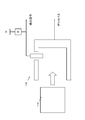
- FIG. 4 is a diagram showing a method for detecting an external device connection in the present embodiment.
- the detection signal changes from “High” to “Low”.
- the detection signal is “High”
- the external device is not connected to the information processing apparatus 200
- the detection signal is “Low”
- the detection signal is input to the connector connection detection unit 1016.
- the connector connection detection unit 1016 determines whether the external device is connected to the information processing apparatus 200 by determining whether the detection signal is “High” or “Low”.
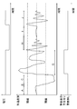
- FIG. 5 is a diagram illustrating a relationship between a change in the output of the acceleration sensor 109 provided in the information processing apparatus 200 according to the present embodiment, a voltage detected by the connector connection detection unit 1016, and a timing at which the CPU 101 performs a warning display. is there.
- the determination unit 1014 outputs a save command to the HDD I / O unit 1018 to perform a shock countermeasure process of the information processing apparatus 200, and sends it to the HDD I / O unit 1018.
- the head withdrawal process of the HDD 112 is performed. Further, the determination unit 1014 displays a message indicating that the HDD head has been retracted on the monitor 114 via the graphics controller 105.
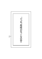
- FIG. 6 shows a warning message displayed on the monitor 114.
- the determination unit 1014 ends the display of a message indicating that the HDD head has been retracted on the monitor 114 via the graphics controller 105.
- the acceleration sensor 109 receives only gravity, and the output level of the acceleration sensor 109 is shown in section E of FIG. Becomes constant.
- the output of the acceleration sensor 109 as shown in a section F of FIG. 5 due to an impact applied to the information processing apparatus 200 when the external device is connected. After the level rises rapidly, the output level of the acceleration sensor 109 repeatedly moves up and down until the information processing apparatus 200 stops.
- the determination unit 1014 determines that the external device is mechanically connected to the information processing apparatus 200 from the voltage detected by the connector connection detection unit 1016, and the monitor 114 is connected via the graphics controller 105. No message indicating that the HDD head has been retracted is not displayed.
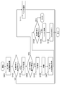
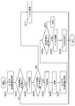
- FIG. 7 is a flowchart showing processing in the present embodiment.
- step S101 the acceleration reading unit 1012 acquires the acceleration value from the acceleration sensor 109, and transfers the acquired acceleration value to the determination unit 1014. The process proceeds to step S102.
- step S102 the determination unit 1014 determines whether the acceleration value transferred from the acceleration reading unit 1012 is equal to or greater than a predetermined value. If the acceleration value is greater than or equal to the predetermined value as in section C of FIG. 5, the process proceeds to step S103. On the other hand, when the acceleration value is less than the predetermined value as in section A in FIG. 5, the process ends.
- step S103 the determination unit 1014 instructs the HDD I / O unit 1018 to retract the head of the HDD 112.
- the HDD I / O unit 1018 receives a head withdrawal command from the determination unit 1014, the HDD I / O unit 1018 retracts the head of the HDD 112. The process proceeds to step S104.
- step S104 the determination unit 1014 determines whether the connector connection detection unit 1016 has detected the connection of the external connector 113.
- the process proceeds to step S111.
- the connector connection detection unit 1016 does not detect the connection of the external connector 113 as in the section D of FIG. 5, the process proceeds to step S105.
- step S105 the determination unit 1014 displays a warning message on the monitor 114 via the system controller 103 and the graphics controller 105.
- the warning message is displayed in FIG.
- the process proceeds to step S106.
- step S106 the HDD I / O unit 1018 waits the head of the HDD 112 at the retracted position. The process proceeds to step S107.
- step S107 the acceleration reading unit 1012 acquires the acceleration value again from the acceleration sensor 109 after a predetermined time, and transfers the acquired acceleration value to the determination unit 1014. The process proceeds to step S108.
- step S108 the determination unit 1014 determines whether the acceleration value transferred from the acceleration reading unit 1012 is equal to or greater than a predetermined value. If the acceleration value is greater than or equal to a predetermined value as in section C of FIG. 5, the information processing apparatus 200 is not stationary and may crash if the head is returned, so the process returns to step S105. On the other hand, when the acceleration value is less than the predetermined value as in section E of FIG. 5, the information processing apparatus 200 is stationary and there is no possibility of crashing even if the head is returned, so the process proceeds to step S109. To do.
- step S109 the determination unit 1014 instructs the HDD I / O unit 1018 to restore the head of the HDD 112.
- the HDD I / O unit 1018 receives a head return command from the determination unit 1014, the HDD I / O unit 1018 returns the head of the HDD 112. The process proceeds to step S110.
- step S110 the CPU 101 finishes displaying the warning message displayed on the monitor 114 via the system controller 103 and the graphics controller 105. The process ends.
- the connector connection detection unit 1016 detects the connection of the external connector 113 in step S104 described above. If the external device is mechanically connected to the information processing device 200 even if the acceleration value exceeds a predetermined value as in the section F of FIG. 5, the external device is mechanically connected to the information processing device 200. Therefore, it is determined that an impact has been applied to the information processing apparatus 200, and the impact countermeasure process of the information processing apparatus 200 is stopped.
- step S111 the determination unit 1014 instructs the HDD I / O unit 1018 to restore the head of the HDD 112.
- the HDD I / O unit 1018 receives a head return command from the determination unit 1014, the HDD I / O unit 1018 returns the head of the HDD 112. The process ends.
- the recovery from HDD protection is performed.
- the head retraction period can be shortened. According to this, even if the HDD protection reacts excessively to an impact generated when the external device is mechanically connected, the HDD immediately recovers, so that the user is not bothered.
- the HDD 112 does not include the acceleration sensor 109 .
- the HDD 112 may include the acceleration sensor 109.
- the HDD I / O unit 1018 acquires the acceleration value from the acceleration sensor 109 and transfers the data to the determination unit 1014.
- FIG. 9 is a diagram illustrating a relationship between a change in the output of the acceleration sensor 109 provided in the information processing apparatus 200 according to the present embodiment, a voltage detected by the connector connection detection unit 1016, and a timing at which the CPU 101 performs a warning display. is there.
- the determination unit 1014 outputs a save command to the HDD I / O unit 1018 to perform a shock countermeasure process of the information processing apparatus 200, and sends it to the HDD I / O unit 1018.
- the head withdrawal process of the HDD 112 is performed. Further, the determination unit 1014 displays a message indicating that the HDD head has been retracted on the monitor 114 via the graphics controller 105.
- the determination unit 1014 ends the display of a message indicating that the HDD head has been retracted on the monitor 114 via the graphics controller 105.
- the output of the acceleration sensor 109 is output as shown in a section H of FIG. 9 due to an impact applied to the information processing apparatus 200 when the external device is connected. After the level rises rapidly, the output level of the acceleration sensor 109 repeats up and down until the information processing apparatus 200 stops.
- the voltage detected by the connector connection detection unit 1016 changes from “High” to “Low”. Therefore, the determination unit 1014 determines that the external device is mechanically connected to the information processing apparatus 200. However, a message indicating that the HDD head has been retracted is not displayed on the monitor 114 via the graphics controller 105.
- the acceleration sensor 109 When an external device is mechanically connected to the information processing apparatus 200 and enters a stationary state, the acceleration sensor 109 receives only gravity, and the output level of the acceleration sensor 109 is constant as shown in section I of FIG. become. Finally, when an external device is mechanically removed from the information processing apparatus 200 by the user, as shown in a section J of FIG. 9 due to an impact applied to the information processing apparatus 200 when the external device is removed, the acceleration sensor 109 After the output level rises rapidly, the output level of the acceleration sensor 109 repeatedly moves up and down until the information processing apparatus 200 stops. When the external device is removed, the voltage detected by the connector connection detection unit 1016 changes from “Low” to “High”, so the determination unit 1014 determines that the external device is mechanically disconnected from the information processing apparatus 200. However, a message indicating that the HDD head has been retracted is not displayed on the monitor 114 via the graphics controller 105.
- FIG. 10 is a flowchart showing processing in the present embodiment. Note that description of the processing described with reference to FIG. 7 is omitted.
- step S201 the acceleration reading unit 1012 acquires the acceleration value from the acceleration sensor 109, and transfers the acquired acceleration value to the determination unit 1014. The process proceeds to step S202.
- step S202 the determination unit 1014 determines whether the acceleration value transferred from the acceleration reading unit 1012 is equal to or greater than a predetermined value. If the acceleration value is greater than or equal to a predetermined value as in section I of FIG. 9, the process proceeds to step S203. On the other hand, when the acceleration value is less than the predetermined value as in section J of FIG. 9, the process ends.
- step S203 the determination unit 1014 instructs the HDD I / O unit 1018 to retract the head of the HDD 112.
- the HDD I / O unit 1018 receives a head withdrawal command from the determination unit 1014, the HDD I / O unit 1018 retracts the head of the HDD 112. The process proceeds to step S204.
- step S204 the determination unit 1014 determines whether the connector connection detection unit 1016 has detected that the external connector 113 has been removed.
- the process proceeds to step S211.
- the connector connection detection unit 1016 does not detect that the external connector 113 has been disconnected as in the section I of FIG. 9, the process proceeds to step S205.
- the voltage detected by the connector connection detection unit 1016 changes from “Low” to “High” will be described. If it is detected that the external device is mechanically disconnected from the information processing apparatus 200 even if the acceleration value exceeds a predetermined value as in the section J of FIG. Therefore, it is determined that an impact has been applied to the information processing apparatus 200, and the impact countermeasure process of the information processing apparatus 200 is stopped.
- step S211 the determination unit 1014 instructs the HDD I / O unit 1018 to restore the head of the HDD 112.
- the HDD I / O unit 1018 receives a head return command from the determination unit 1014, the HDD I / O unit 1018 returns the head of the HDD 112. The process ends.
- the second embodiment when it is detected that an external device has been mechanically removed from the information processing apparatus 200 in response to a temporary impact applied to the information processing apparatus 200, recovery from HDD protection is performed. By speeding up the process, the false detection period can be shortened. According to this, even if the HDD protection reacts excessively to the impact generated when the external device is mechanically removed, the HDD immediately recovers, so that the user is not bothered.
Landscapes
- Signal Processing For Digital Recording And Reproducing (AREA)
- User Interface Of Digital Computer (AREA)
Abstract
本技術の開示での課題は、衝撃を検出する感度を下げることなく、情報処理装置の性能低下を防止することである。課題を解決するために、本実施形態の一例によれば、処理装置は、自装置に加えられる加速度を検出する加速度センサと、自装置に外部機器が機械的に接続されたことを検出する接続検出部と、前記加速度センサより検出された加速度に応じて自装置内の機械的動作を伴う機器に衝撃対策を行うとともに、前記接続検出手段により前記外部機器が接続されたことを検出した場合に前記衝撃対策を中止する制御部とを有する。
Description
本発明は、処理装置、処理装置の制御方法及び制御プログラムに関する。
情報処理装置等の落下時に、例えば自動的にHDD(Hard Disk Drive)のヘッドを退避して衝撃対策処理を実行する機能がある。落下の検出は加速度センサ等で行い、装置の加速度が所定値以上の場合、装置が落下していると判定する。
加速度センサを用いて落下を検出する方法では、情報処理装置に触れる等により振動を与えただけで、加速度が所定値以上となってしまった場合、落下を誤検出してしまう。
例えば、録画機器の動作モードに応じて、落下判定条件を制御する技術がある(特許文献1)。
また、例えば、加速度センサの出力信号から機器の落下状態を検出する技術がある(特許文献2)。
衝撃を検出する感度が敏感だと外部機器接続時に衝撃対策処理を実行してしまい、画面に警告が表示される等、HDDの復帰に時間がかかりユーザに煩わしさを与えてしまう。一方、衝撃を検出する感度を下げて誤検出による衝撃対策処理が実行されないようにすると、装置の落下等の本来検出しなければならない衝撃の検出が遅れてしまう。
本発明の課題は、衝撃を検出する感度を下げることなく、情報処理装置の性能低下を防止することである。
上記課題を解決するために、本実施形態の一例によれば、処理装置は、自装置に加えられる加速度を検出する加速度センサと、自装置に外部機器が機械的に接続されたことを検出する接続検出部と、前記加速度センサより検出された加速度に応じて自装置内の機械的動作を伴う機器に衝撃対策を行うとともに、前記接続検出手段により前記外部機器が接続されたことを検出した場合に前記衝撃対策を中止する制御部とを有する。
本実施形態の一側面によれば、加速度センサにより検出された加速度が当該装置に対する外部機器の接続に起因するものと判断された場合、加速度検出に応じて行う当該装置の衝撃対策処理を中止することで、当該装置の性能低下を防止することができる。
以下、本実施形態における情報処理装置について説明する。
<実施の形態1>
図1は、本実施形態における情報処理装置200のハードウェア構成の一例を簡略的に示すブロック図である。情報処理装置200は、CPU(Central Processing Unit)101によって全体が制御されている。
図1は、本実施形態における情報処理装置200のハードウェア構成の一例を簡略的に示すブロック図である。情報処理装置200は、CPU(Central Processing Unit)101によって全体が制御されている。
CPU101及びRAM(Random Access Memory)102には、システムコントローラ103が接続されている。システムコントローラ103は、CPU101とRAM102との間のデータ転送や、CPU101とバス104との間のデータ転送を制御する。さらに、システムコントローラ103には、バス104を介して、グラフィックスコントローラ105、ROM(Read Only Memory)106、オーディオコントローラ108、MPU(Micro Processing Unit)111、キーボードコントローラ50及びHDD(Hard Disk Drive)112が接続されている。
RAM102には、CPU101に実行させるOS(Operating System)のプログラムやアプリケーションプログラムの少なくとも一部が一時的に格納される。また、RAM102には、CPU101による処理に必要な各種データが格納される。
グラフィックスコントローラ105には、LCD(Liquid Crystal Monitor)等のモニタ114が接続されており、CPU101からの命令に従って画像をモニタ114の画面に表示させる。
ROM106には、例えば、BIOS(Basic Input/Output System)プログラムが格納される。
オーディオコントローラ108には、スピーカ115が接続されており、CPU101
からの命令に従って音声をスピーカ115から発生させる。
からの命令に従って音声をスピーカ115から発生させる。
MPU111は、加速度センサ109と接続されている。MPU111は、加速度センサ109から取得した値をCPU101に送信する。加速度センサ109は、例えば、2軸(X/Y軸)または3軸(X/Y/Z軸)上のそれぞれに加えられる加速度の変動を検知し、アナログ出力を行うものである。
キーボードコントローラ50には、キーボード20及びマウス30が接続されており、キーボード20またはマウス30から送られてくる信号を、バス104を介してCPU101に送信する。
HDD112は、媒体であるハードディスク、ハードディスクからのリードやそれら媒体へのライトのためにアクセスするヘッドを備えている。ハードディスクには、OSやアプリケーションのプログラム、各種データが格納される。
このようなハードウェアによって、情報処理装置200の処理機能を実現することができる。
図2は、本実施形態における情報処理装置200の外観を示す図である。情報処理装置200は、DC(Direct Current)-INコネクタ202、CRT(Cathode Ray Tube)コネクタ204及びUSB(Universal Serial Bus)コネクタ206を有する。DC-INコネクタ202、CRTコネクタ204及びUSBコネクタ206は、外部機器が機械的に着脱可能なコネクタである。
図3は、本実施形態におけるCPU101と周辺機器の構成の一例を簡略的に示すブロック図である。
CPU101は、加速度読込部1012、判定部1014、コネクタ接続検出部1016、HDDI/O部1018として機能する。
加速度読込部1012は、加速度センサ109から加速度値を取得し、判定部1014にデータを転送する。
判定部1014は、読込んだ加速度値が所定値以上か判定を行い、その判定結果からHDDI/O部1018にヘッド退避を指示する。また、判定部1014は、HDDI/O部1018にヘッド復帰を指示する。
コネクタ接続検出部1016は、外部コネクタ113の接続を検出する。コネクタ接続検出部1016は、接続を検出する信号の立ち上がり/立下りで、外部コネクタ113の接続を検出する。
HDDI/O部1018は、HDD112のI/Oを制御する。HDDI/O部1018は、判定部1014からヘッド退避の指示を受信した場合、HDD112にヘッド退避のコマンドを発行し、ヘッド退避を実行する。また、HDDI/O部1018は、判定部1014からヘッド復帰の指示を受信した場合、HDD112にヘッド復帰のコマンドを発行し、ヘッド復帰を実行する。
図4は、本実施形態における外部機器接続の検出方法を示す図である。外部コネクタ113が情報処理装置側コネクタ116に接続されると、例えば、検出信号が「High」から「Low」に変わる。検出信号は、「High」の時、外部機器が情報処理装置200に接続されていないことを示し、「Low」の時、外部機器が情報処理装置200に接続されていることを示す。検出信号は、コネクタ接続検出部1016に入力する。コネクタ接続検出部1016は、当該検出信号が「High」または「Low」であるかを判定することにより、外部機器が情報処理装置200に接続されているか否かを判定する。
図5は、本実施形態における情報処理装置200に備えられた加速度センサ109の出力の変化と、コネクタ接続検出部1016が検出する電圧と、CPU101が警告表示を行うタイミングとの関係を示す図である。
まず、情報処理装置200が、例えば、人手に持たれて自然な運動状態にある時、図5の区間Aに示すように、加速度センサ109の出力は比較的緩やかに変化する。次に、情報処理装置200が、落下により無重力状態になると、図5の区間Bに示すように、加速度は急激に変化し、加速度センサ109の出力レベルは急激に変化する。そして、図5の区間Cに示すように、自由落下での加速度はほぼ一定となる。区間B及びCで、加速度値が所定値を超えると、判定部1014は、情報処理装置200の衝撃対策処理を行うため、HDDI/O部1018に退避命令を出力し、HDDI/O部1018にHDD112のヘッド退避処理を行わせる。また、判定部1014は、グラッフィクスコントローラ105を介してモニタ114にHDDのヘッド退避を行ったことを示すメッセージを表示する。図6に、モニタ114に表示される警告メッセージを示す。
その後、情報処理装置200が、例えば、床に落下する前に、人手によって落下の阻止をされると、図5の区間Dに示すように、加速度センサ109の出力レベルは急激に上昇した後、情報処理装置200が、人手で静止するまでの間、加速度センサ109の出力レベルは上下動を繰り返す。この時、HDD112のヘッドは、既に退避位置に移動しているため、ヘッドが損傷することはない。また、判定部1014は、グラッフィクスコントローラ105を介してモニタ114にHDDのヘッド退避を行ったことを示すメッセージの表示を終了する。
情報処理装置200が、人手によって、例えば、机等に置かれて静止状態になると、加速度センサ109は重力のみを受けた状態となり、図5の区間Eに示すように、加速度センサ109の出力レベルは一定になる。
さらに、ユーザによって、情報処理装置200に外部機器が機械的に接続されると、外部機器の接続時に情報処理装置200に加わる衝撃によって、図5の区間Fに示すように、加速度センサ109の出力レベルは急激に上昇した後、情報処理装置200が、静止するまでの間、加速度センサ109の出力レベルは上下動を繰り返す。また、外部機器の接続時には、コネクタ接続検出部1016が検出する電圧から、判定部1014は、情報処理装置200に外部機器が機械的に接続されたと判定し、グラッフィクスコントローラ105を介してモニタ114にHDDのヘッド退避を行ったことを示すメッセージの表示を行わない。
図7は本実施形態における処理を示すフローチャートである。
ステップS101において、加速度読込部1012は、加速度センサ109から加速度値を取得し、判定部1014に取得した加速度値を転送する。処理はステップS102へ移行する。
ステップS102において、判定部1014は、加速度読込部1012から転送された加速度値が所定値以上か否かを判定する。図5の区間Cのように加速度値が所定値以上の場合、処理はステップS103へ移行する。一方、図5の区間Aのように、加速度値が所定値未満の場合、処理は終了する。
ステップS103において、判定部1014は、HDDI/O部1018に、HDD112のヘッドを退避するよう命令する。HDDI/O部1018は、判定部1014からのヘッド退避の命令を受けると、HDD112のヘッドを退避する。処理はステップS104へ移行する。
ステップS104において、判定部1014は、コネクタ接続検出部1016が、外部コネクタ113の接続を検出したか否かを判定する。コネクタ接続検出部1016が、図5の区間Fのように、外部コネクタ113の接続を検出した場合、処理はステップS111へ移行する。一方、コネクタ接続検出部1016が、図5の区間Dのように、外部コネクタ113の接続を検出しない場合、処理はステップS105へ移行する。
ステップS105において、判定部1014は、システムコントローラ103及びグラフィックスコントローラ105を介して、モニタ114に警告メッセージを表示する。当該警告メッセージを図6に表示する。処理はステップS106へ移行する。
ステップS106において、HDDI/O部1018は、HDD112のヘッドを退避位置に待機させる。処理はステップS107へ移行する。
ステップS107において、加速度読込部1012は、所定時間経過後、加速度センサ109から再び加速度値を取得し、判定部1014に取得した加速度値を転送する。処理はステップS108へ移行する。
ステップS108において、判定部1014は、加速度読込部1012から転送された加速度値が所定値以上か否かを判定する。図5の区間Cのように、加速度値が所定値以上の場合は、情報処理装置200が静止しておらず、ヘッドを復帰させるとクラッシュするおそれがあるため、処理はステップS105に戻る。一方、図5の区間Eのように、加速度値が所定値未満の場合は、情報処理装置200が静止しており、ヘッドを復帰させてもクラッシュするおそれがないため、処理はステップS109へ移行する。
ステップS109において、判定部1014は、HDDI/O部1018に、HDD112のヘッドを復帰するよう命令する。HDDI/O部1018は、判定部1014からヘッド復帰の命令を受けると、HDD112のヘッドを復帰する。処理はステップS110へ移行する。
ステップS110において、CPU101は、システムコントローラ103及びグラフィックスコントローラ105を介して、モニタ114に表示した警告のメッセージの表示を終了する。処理は終了する。
ここで、上述したステップS104において、コネクタ接続検出部1016が、外部コネクタ113の接続を検出した場合について説明する。図5の区間Fのように、加速度値が所定値を超えても、外部機器が情報処理装置200に機械的に接続されたことを検出した場合は、外部機器を情報処理装置200に機械的に接続するために、情報処理装置200に衝撃が加わったと判定し、情報処理装置200の衝撃対策処理を中止する。
ステップS111において、判定部1014は、HDDI/O部1018に、HDD112のヘッドを復帰するよう命令する。HDDI/O部1018は、判定部1014からのヘッド復帰の命令を受けると、HDD112のヘッドを復帰する。処理は終了する。
以上、実施の形態1によれば、情報処理装置200に加わる一時的な衝撃に対して、情報処理装置200に外部機器が機械的に接続されたことを検出した時は、HDD保護からの復帰を早めることで、ヘッド退避期間を短縮することができる。これによれば、外部機器を機械的に接続する時に発生する衝撃に対してHDD保護が過度に反応した場合でも即座に復帰するため、ユーザに煩わしさを与えることがなくなる。
なお、実施の形態1では、HDD112に加速度センサ109が内蔵されていない場合について説明したが、図8に示すように、HDD112に加速度センサ109が内蔵されていても良い。この場合、HDDI/O部1018が、加速度センサ109から加速度値を取得し、判定部1014にデータを転送する。
また、実施の形態1では、外部機器の情報処理装置200への機械的接続を検出することについて説明したが、例えば、プラグイン機能を用いて、外部機器が情報処理装置200に接続されたことを検出しても良い。
<実施の形態2>
実施の形態1では、情報処理装置200に外部機器が機械的に接続される場合について説明したが、実施の形態2では、情報処理装置200から外部機器が機械的に外される場合について説明する。
実施の形態1では、情報処理装置200に外部機器が機械的に接続される場合について説明したが、実施の形態2では、情報処理装置200から外部機器が機械的に外される場合について説明する。
図9は、本実施形態における情報処理装置200に備えられた加速度センサ109の出力の変化と、コネクタ接続検出部1016が検出する電圧と、CPU101が警告表示を行うタイミングとの関係を示す図である。
まず、情報処理装置200が、例えば、人手に持たれて自然な運動状態にある時、図9の区間Aに示すように、加速度センサ109の出力は比較的緩やかに変化する。次に、情報処理装置200が、落下により無重力状態になると、図9の区間Bに示すように、加速度は急激に変化し、加速度センサ109の出力レベルは急激に変化する。そして、図9の区間Cに示すように、自由落下での加速度はほぼ一定となる。区間B及びCで、加速度値が所定値を超えると、判定部1014は、情報処理装置200の衝撃対策処理を行うため、HDDI/O部1018に退避命令を出力し、HDDI/O部1018にHDD112のヘッド退避処理を行わせる。また、判定部1014は、グラッフィクスコントローラ105を介してモニタ114にHDDのヘッド退避を行ったことを示すメッセージを表示する。
その後、情報処理装置200が、例えば、床に落下する前に、人手によって落下の阻止をされると、図9の区間Gに示すように、加速度センサ109の出力レベルは急激に上昇した後、情報処理装置200が、人手で静止するまでの間、加速度センサ109の出力レベルは上下動を繰り返す。この時、HDD112のヘッドは、既に退避位置に移動しているため、ヘッドが損傷することはない。また、判定部1014は、グラッフィクスコントローラ105を介してモニタ114にHDDのヘッド退避を行ったことを示すメッセージの表示を終了する。
さらに、ユーザによって、情報処理装置200に外部機器が機械的に接続されると、外部機器の接続時に情報処理装置200に加わる衝撃によって、図9の区間Hに示すように、加速度センサ109の出力レベルは急激に上昇した後、情報処理装置200が静止するまでの間、加速度センサ109の出力レベルは上下動を繰り返す。また、外部機器の接続時には、コネクタ接続検出部1016が検出する電圧が「High」から「Low」に変化するため、判定部1014は、情報処理装置200に外部機器が機械的に接続されたと判定し、グラッフィクスコントローラ105を介してモニタ114にHDDのヘッド退避を行ったことを示すメッセージの表示を行わない。
情報処理装置200に外部機器が機械的に接続されて、静止状態になると、加速度センサ109は重力のみを受けた状態となり、図9の区間Iに示すように、加速度センサ109の出力レベルは一定になる。最後に、ユーザによって、情報処理装置200から外部機器が機械的に外されると、外部機器を外す時に情報処理装置200に加わる衝撃によって、図9の区間Jに示すように、加速度センサ109の出力レベルは急激に上昇した後、情報処理装置200が静止するまでの間、加速度センサ109の出力レベルは上下動を繰り返す。また、外部機器を外す時には、コネクタ接続検出部1016が検出する電圧が「Low」から「High」に変化するため、判定部1014は、情報処理装置200に外部機器が機械的に外されたと判定し、グラッフィクスコントローラ105を介してモニタ114にHDDのヘッド退避を行ったことを示すメッセージの表示を行わない。
図10は本実施形態における処理を示すフローチャートである。なお、図7を用いて説明した処理については説明を省略する。
ステップS201において、加速度読込部1012は、加速度センサ109から加速度値を取得し、判定部1014に取得した加速度値を転送する。処理はステップS202へ移行する。
ステップS202において、判定部1014は、加速度読込部1012から転送された加速度値が所定値以上か否かを判定する。図9の区間Iのように加速度値が所定値以上の場合、処理はステップS203へ移行する。一方、図9の区間Jのように、加速度値が所定値未満の場合、処理は終了する。
ステップS203において、判定部1014は、HDDI/O部1018に、HDD112のヘッドを退避するよう命令する。HDDI/O部1018は、判定部1014からのヘッド退避の命令を受けると、HDD112のヘッドを退避する。処理はステップS204へ移行する。
ステップS204において、判定部1014は、コネクタ接続検出部1016が、外部コネクタ113が外されたことを検出したか否かを判定する。コネクタ接続検出部1016が、図9の区間Jのように、外部コネクタ113が外されたことを検出した場合、処理はステップS211へ移行する。一方、コネクタ接続検出部1016が、図9の区間Iのように、外部コネクタ113が外されたことを検出しない場合、処理はステップS205へ移行する。本実施形態においては、コネクタ接続検出部1016が検出する電圧が「Low」から「High」に変化した場合について説明する。図9の区間Jのように、加速度値が所定値を超えても、外部機器が情報処理装置200から機械的に外されたことを検出した場合は、外部機器を情報処理装置200から機械的に外すために、情報処理装置200に衝撃が加わったと判定し、情報処理装置200の衝撃対策処理を中止する。
ステップS211において、判定部1014は、HDDI/O部1018に、HDD112のヘッドを復帰するよう命令する。HDDI/O部1018は、判定部1014からのヘッド復帰の命令を受けると、HDD112のヘッドを復帰する。処理は終了する。
以上、実施の形態2によれば、情報処理装置200に加わる一時的な衝撃に対して、情報処理装置200から外部機器が機械的に外されたことを検出した時は、HDD保護からの復帰を早めることで、誤検出の期間を短縮することができる。これによれば、外部機器を機械的に外す時に発生する衝撃に対してHDD保護が過度に反応した場合でも即座に復帰するため、ユーザに煩わしさを与えることがなくなる。
以上、本発明の例示的な実施の形態の情報処理装置について説明したが、本発明は、具体的に開示された実施の形態に限定されるものではなく、特許請求の範囲から逸脱することなく、種々の変形や変更が可能である。
101 CPU
1012 加速度読込部
1014 判定部
1016 コネクタ接続検出部
1018 HDDI/O部
102 RAM
103 システムコントローラ
104 バス
105 グラフィックスコントローラ
106 ROM
108 オーディオコントローラ
109 加速度センサ
111 MPU
112 HDD
113 外部コネクタ
114 モニタ
115 スピーカ
116 情報処理装置側コネクタ
20 キーボード
200 情報処理装置
202 DC-INコネクタ
204 CRTコネクタ
206 USBコネクタ
30 マウス
50 キーボードコントローラ
1012 加速度読込部
1014 判定部
1016 コネクタ接続検出部
1018 HDDI/O部
102 RAM
103 システムコントローラ
104 バス
105 グラフィックスコントローラ
106 ROM
108 オーディオコントローラ
109 加速度センサ
111 MPU
112 HDD
113 外部コネクタ
114 モニタ
115 スピーカ
116 情報処理装置側コネクタ
20 キーボード
200 情報処理装置
202 DC-INコネクタ
204 CRTコネクタ
206 USBコネクタ
30 マウス
50 キーボードコントローラ
Claims (5)
- 自装置に加えられる加速度を検出する加速度センサと、
自装置に外部機器が機械的に接続されたことを検出する接続検出部と、
前記加速度センサより検出された加速度に応じて自装置内の機械的動作を伴う機器に衝撃対策を行うとともに、前記接続検出手段により前記外部機器が接続されたことを検出した場合に前記衝撃対策を中止する制御部と、
を有することを特徴とする処理装置。 - 前記機械的動作を伴う機器は、媒体と前記媒体にアクセスするヘッドを有する記憶装置であり、
前記制御装置は、前記加速度センサが所定値以上の加速度を検出した場合に前記ヘッドを退避するように制御するとともに、退避制御中に前記接続検出手段が接続を検出した場合には、前記ヘッドを復帰させるように制御することを特徴とする請求項1記載の処理装置。 - 前記機械的動作を伴う機器は、媒体と前記媒体にアクセスするヘッドを有する記憶装置であり、
前記制御装置は、前記加速度センサが所定値以上の加速度を検出した場合に前記ヘッドを退避するように制御するとともに、退避制御中に前記接続検出手段が自装置から前記外部機器の接続解除を検出した場合には、前記ヘッドを復帰させるように制御することを特徴とする請求項1記載の処理装置。 - 制御部と、自装置に加えられる加速度を検出する加速度センサとを有する処理装置の制御方法において、
前記制御部は、
前記処理装置に外部機器が機械的に接続されたことを検出し、
前記加速度センサより検出された加速度に応じて前記処理装置内の機械的動作を伴う機器に衝撃対策を行うとともに、前記外部機器が接続されたことを検出した場合に前記衝撃対策を中止する、
ことを特徴とする処理装置の制御方法。 - 自装置に加えられる加速度を検出する加速度センサを有する処理装置を制御する制御プログラムであって、
前記処理装置に、
前記処理装置に外部機器が機械的に接続されたことを検出し、
前記加速度センサより検出された加速度に応じて前記処理装置内の機械的動作を伴う機器に衝撃対策を行うとともに、前記外部機器が接続されたことを検出した場合に前記衝撃対策を中止する、
処理を実行させるための制御プログラム。
Priority Applications (3)
| Application Number | Priority Date | Filing Date | Title |
|---|---|---|---|
| PCT/JP2011/001657 WO2012127520A1 (ja) | 2011-03-18 | 2011-03-18 | 処理装置、処理装置の制御方法及び制御プログラム |
| JP2013505608A JP5668841B2 (ja) | 2011-03-18 | 2011-03-18 | 処理装置、処理装置の制御方法及び制御プログラム |
| US13/974,668 US20130342928A1 (en) | 2011-03-18 | 2013-08-23 | Information processing device, information processing method, and storage medium |
Applications Claiming Priority (1)
| Application Number | Priority Date | Filing Date | Title |
|---|---|---|---|
| PCT/JP2011/001657 WO2012127520A1 (ja) | 2011-03-18 | 2011-03-18 | 処理装置、処理装置の制御方法及び制御プログラム |
Related Child Applications (1)
| Application Number | Title | Priority Date | Filing Date |
|---|---|---|---|
| US13/974,668 Continuation US20130342928A1 (en) | 2011-03-18 | 2013-08-23 | Information processing device, information processing method, and storage medium |
Publications (1)
| Publication Number | Publication Date |
|---|---|
| WO2012127520A1 true WO2012127520A1 (ja) | 2012-09-27 |
Family
ID=46878727
Family Applications (1)
| Application Number | Title | Priority Date | Filing Date |
|---|---|---|---|
| PCT/JP2011/001657 Ceased WO2012127520A1 (ja) | 2011-03-18 | 2011-03-18 | 処理装置、処理装置の制御方法及び制御プログラム |
Country Status (3)
| Country | Link |
|---|---|
| US (1) | US20130342928A1 (ja) |
| JP (1) | JP5668841B2 (ja) |
| WO (1) | WO2012127520A1 (ja) |
Families Citing this family (1)
| Publication number | Priority date | Publication date | Assignee | Title |
|---|---|---|---|---|
| JP6068308B2 (ja) * | 2013-09-27 | 2017-01-25 | レノボ・シンガポール・プライベート・リミテッド | 携帯型情報処理装置、その磁気ディスク装置保護方法、及びコンピュータが実行可能なプログラム |
Citations (2)
| Publication number | Priority date | Publication date | Assignee | Title |
|---|---|---|---|---|
| JP2005044435A (ja) * | 2003-07-22 | 2005-02-17 | Sony Corp | 携帯型電子機器 |
| JP2007335049A (ja) * | 2006-06-19 | 2007-12-27 | Sony Ericsson Mobilecommunications Japan Inc | 携帯端末、携帯端末システム、携帯端末のハードディスクドライブ保護方法 |
Family Cites Families (4)
| Publication number | Priority date | Publication date | Assignee | Title |
|---|---|---|---|---|
| KR100630697B1 (ko) * | 2004-08-11 | 2006-10-02 | 삼성전자주식회사 | 휴대형 모바일 장치의 하드디스크 드라이브 보호 방법 및이에 적합한 장치 |
| JP4519626B2 (ja) * | 2004-12-17 | 2010-08-04 | 株式会社東芝 | 電子機器およびディスク保護方法 |
| JP2007115309A (ja) * | 2005-10-19 | 2007-05-10 | Hitachi Global Storage Technologies Netherlands Bv | 磁気ディスク装置 |
| JP2009043170A (ja) * | 2007-08-10 | 2009-02-26 | Fujitsu Ltd | 情報処理装置、情報処理装置の制御方法、および情報処理装置の制御プログラム |
-
2011
- 2011-03-18 JP JP2013505608A patent/JP5668841B2/ja not_active Expired - Fee Related
- 2011-03-18 WO PCT/JP2011/001657 patent/WO2012127520A1/ja not_active Ceased
-
2013
- 2013-08-23 US US13/974,668 patent/US20130342928A1/en not_active Abandoned
Patent Citations (2)
| Publication number | Priority date | Publication date | Assignee | Title |
|---|---|---|---|---|
| JP2005044435A (ja) * | 2003-07-22 | 2005-02-17 | Sony Corp | 携帯型電子機器 |
| JP2007335049A (ja) * | 2006-06-19 | 2007-12-27 | Sony Ericsson Mobilecommunications Japan Inc | 携帯端末、携帯端末システム、携帯端末のハードディスクドライブ保護方法 |
Also Published As
| Publication number | Publication date |
|---|---|
| JPWO2012127520A1 (ja) | 2014-07-24 |
| US20130342928A1 (en) | 2013-12-26 |
| JP5668841B2 (ja) | 2015-02-12 |
Similar Documents
| Publication | Publication Date | Title |
|---|---|---|
| JP4471389B2 (ja) | デュアル加速度センサシステム | |
| CN103546643A (zh) | 一种及时提示移动智能设备跌落损坏的方法和装置 | |
| KR20130136671A (ko) | 정전 용량 방식의 터치 패널 센서 및 이를 포함하는 터치 패널 표시 장치 | |
| JP6918886B2 (ja) | 情報処理装置、及び制御方法 | |
| CN102306497A (zh) | 信息处理设备和用于该设备的头退避处理方法 | |
| JP5668841B2 (ja) | 処理装置、処理装置の制御方法及び制御プログラム | |
| US7626355B2 (en) | Portable electronic device and method to protect same | |
| US20050213242A1 (en) | Magnetic disk apparatus and information processing apparatus | |
| US11450289B2 (en) | Display device and method of protecting the same | |
| CN102110455B (zh) | 具有电子控制系统的可携式设备及其控制方法 | |
| JP2002259066A (ja) | 情報処理装置 | |
| JP4463771B2 (ja) | ストレージ装置 | |
| CN111193826A (zh) | 终端保护方法、装置、存储介质和电子设备 | |
| US20170228008A1 (en) | Electronic apparatus, control method thereof, and storage medium | |
| CN104461405B (zh) | 数据应急保护方法及电子设备 | |
| JP6844894B2 (ja) | 情報処理装置、タッチパネル入力復旧方法、及びプログラム | |
| JPWO2014112039A1 (ja) | 情報処理装置、情報処理装置制御方法及び情報処理装置制御プログラム | |
| US20090070509A1 (en) | Method of detecting and protecting falling portable computer hard disk through software monitoring driver | |
| JP2013012065A (ja) | 情報処理装置およびタッチパネル制御方法 | |
| JP4930861B2 (ja) | 画像形成装置 | |
| JP2006318485A (ja) | 指紋データ生成装置、プログラム | |
| JP2004355775A (ja) | ハードディスクユニット及びその落下基準時間の設定又は確認方法 | |
| KR101768356B1 (ko) | 신속 응답 용량성 터치 스크린 디바이스 | |
| US20100259847A1 (en) | Portable apparatus having electronic control system and control method thereof | |
| US9679596B2 (en) | Protection of a magnetic disk unit on a portable computing device |
Legal Events
| Date | Code | Title | Description |
|---|---|---|---|
| 121 | Ep: the epo has been informed by wipo that ep was designated in this application |
Ref document number: 11861753 Country of ref document: EP Kind code of ref document: A1 |
|
| ENP | Entry into the national phase |
Ref document number: 2013505608 Country of ref document: JP Kind code of ref document: A |
|
| NENP | Non-entry into the national phase |
Ref country code: DE |
|
| 122 | Ep: pct application non-entry in european phase |
Ref document number: 11861753 Country of ref document: EP Kind code of ref document: A1 |