WO2012124731A1 - 管の超音波検査装置及び管の超音波検査方法 - Google Patents
管の超音波検査装置及び管の超音波検査方法 Download PDFInfo
- Publication number
- WO2012124731A1 WO2012124731A1 PCT/JP2012/056556 JP2012056556W WO2012124731A1 WO 2012124731 A1 WO2012124731 A1 WO 2012124731A1 JP 2012056556 W JP2012056556 W JP 2012056556W WO 2012124731 A1 WO2012124731 A1 WO 2012124731A1
- Authority
- WO
- WIPO (PCT)
- Prior art keywords
- tube
- probe
- inspected
- ultrasonic
- inspection
- Prior art date
Links
Images
Classifications
-
- G—PHYSICS
- G01—MEASURING; TESTING
- G01N—INVESTIGATING OR ANALYSING MATERIALS BY DETERMINING THEIR CHEMICAL OR PHYSICAL PROPERTIES
- G01N29/00—Investigating or analysing materials by the use of ultrasonic, sonic or infrasonic waves; Visualisation of the interior of objects by transmitting ultrasonic or sonic waves through the object
- G01N29/22—Details, e.g. general constructional or apparatus details
- G01N29/26—Arrangements for orientation or scanning by relative movement of the head and the sensor
- G01N29/265—Arrangements for orientation or scanning by relative movement of the head and the sensor by moving the sensor relative to a stationary material
-
- G—PHYSICS
- G01—MEASURING; TESTING
- G01N—INVESTIGATING OR ANALYSING MATERIALS BY DETERMINING THEIR CHEMICAL OR PHYSICAL PROPERTIES
- G01N29/00—Investigating or analysing materials by the use of ultrasonic, sonic or infrasonic waves; Visualisation of the interior of objects by transmitting ultrasonic or sonic waves through the object
- G01N29/04—Analysing solids
- G01N29/043—Analysing solids in the interior, e.g. by shear waves
-
- G—PHYSICS
- G01—MEASURING; TESTING
- G01N—INVESTIGATING OR ANALYSING MATERIALS BY DETERMINING THEIR CHEMICAL OR PHYSICAL PROPERTIES
- G01N29/00—Investigating or analysing materials by the use of ultrasonic, sonic or infrasonic waves; Visualisation of the interior of objects by transmitting ultrasonic or sonic waves through the object
- G01N29/22—Details, e.g. general constructional or apparatus details
- G01N29/225—Supports, positioning or alignment in moving situation
-
- F—MECHANICAL ENGINEERING; LIGHTING; HEATING; WEAPONS; BLASTING
- F16—ENGINEERING ELEMENTS AND UNITS; GENERAL MEASURES FOR PRODUCING AND MAINTAINING EFFECTIVE FUNCTIONING OF MACHINES OR INSTALLATIONS; THERMAL INSULATION IN GENERAL
- F16L—PIPES; JOINTS OR FITTINGS FOR PIPES; SUPPORTS FOR PIPES, CABLES OR PROTECTIVE TUBING; MEANS FOR THERMAL INSULATION IN GENERAL
- F16L2101/00—Uses or applications of pigs or moles
- F16L2101/30—Inspecting, measuring or testing
-
- G—PHYSICS
- G01—MEASURING; TESTING
- G01N—INVESTIGATING OR ANALYSING MATERIALS BY DETERMINING THEIR CHEMICAL OR PHYSICAL PROPERTIES
- G01N2291/00—Indexing codes associated with group G01N29/00
- G01N2291/04—Wave modes and trajectories
- G01N2291/044—Internal reflections (echoes), e.g. on walls or defects
-
- G—PHYSICS
- G01—MEASURING; TESTING
- G01N—INVESTIGATING OR ANALYSING MATERIALS BY DETERMINING THEIR CHEMICAL OR PHYSICAL PROPERTIES
- G01N2291/00—Indexing codes associated with group G01N29/00
- G01N2291/26—Scanned objects
- G01N2291/263—Surfaces
- G01N2291/2636—Surfaces cylindrical from inside
Definitions
- the present invention relates to a tube ultrasonic inspection apparatus and a tube ultrasonic inspection method, and more particularly, to a tube ultrasonic inspection apparatus and a tube for inspecting damage to a tube such as a boiler tube and a heat exchanger tube by a water immersion ultrasonic flaw detection method.
- the present invention relates to an ultrasonic inspection method.
- an ultrasonic flaw detection method has been proposed as a non-destructive inspection method for these tubes.
- a probe is inserted deep inside the tube to be inspected.
- the probe it is important that the probe can be smoothly inserted into the tube to be inspected.
- the probe In the inspection, the probe must be placed in an appropriate position in the tube for inspection.
- Patent Document 1 For example, a technique is known that attempts to position a probe while smoothing the movement of the probe in a tube with a spring guide and an acrylic shoe (see Patent Document 1). In addition, a technique for positioning the probe while smoothing the movement of the probe in the tube with a roller or a spring is known (see Patent Document 2).
- the movement of the probe in the tube is not sufficiently smooth, and the positioning of the probe is not sufficiently accurate.
- the shape of the tube to be inspected is different, it is difficult to smoothly move the probe in the tube and accurately position the probe.
- An object of the present invention is to provide an ultrasonic inspection apparatus for a tube and an ultrasonic inspection of a tube that can move the probe smoothly in the tube, accurately position the probe in the tube, and inspect the tube for damage. It is to provide a method.
- An ultrasonic inspection apparatus for a tube includes a probe that transmits ultrasonic waves and receives ultrasonic echo waves, and reflects the ultrasonic waves transmitted from the probe to a tube to be inspected. Based on the inspection probe portion in which the mirror that reflects the echo wave from the tube to be inspected to the probe is housed, the ultrasonic wave transmitted by the probe, and the echo wave received by the probe
- a data processing unit for processing the inspection data of the inspection tube a holding unit for holding the inspection probe portion, a magnet for sucking the inner tube wall of the inspection tube, and a tube of the inspection tube
- a traveling wheel traveling on the wall has a centering member provided on one side of the outer periphery.
- the tube further includes a rotation mechanism that rotates a mirror around the transmission axis of the ultrasonic wave from the probe to the mirror, and the transmission shaft is provided by the holding portion of the centering member.
- the inspection probe may be held so that is parallel to the central axis of the tube to be inspected.
- the centering member is provided on one side of the outer periphery with a magnet that attracts the tube wall of the tube to be inspected and a traveling wheel that travels on the tube wall of the tube to be inspected.
- the length from the other side of the outer periphery of the centering member to the transmission shaft is shorter than the length from one side of the outer periphery of the centering member to the transmission shaft. Also good.
- An ultrasonic inspection method for a tube is an ultrasonic inspection method for a tube using the above-described ultrasonic inspection apparatus for a tube, and while sucking the tube wall of the tube to be inspected by the magnet, The inspection probe is caused to travel within the inspection tube by the traveling wheel, and inspection data of the inspection tube is processed by the data processing unit.
- the tube inner diameter of the tube to be inspected may not be constant.
- the tube to be inspected may be bent.
- a probe that transmits ultrasonic waves and receives ultrasonic echo waves, and reflects the ultrasonic waves transmitted from the probe to the test tube, Inspection probe containing a mirror that reflects the echo wave of the probe to the probe, and the inspection data of the tube to be inspected based on the ultrasonic wave transmitted by the probe and the echo wave received by the probe
- a data processing unit, a holding unit that holds the inspection probe unit, a magnet that attracts the inner tube wall of the tube to be inspected, and a traveling wheel that travels on the tube wall of the tube to be inspected are on one side of the outer periphery. Since the centering member is provided, the probe can be smoothly moved in the tube, the probe can be accurately positioned in the tube, and the tube can be inspected for damage.
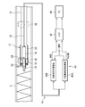
- FIG. 1 is a view showing an inspection probe section of a tube ultrasonic inspection apparatus according to the present embodiment
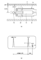
- FIG. 4 is a view showing a centering member of the tube ultrasonic inspection apparatus according to the present embodiment
- FIG. It is a figure which shows the use condition of the ultrasonic inspection apparatus of the pipe
- an inspection probe 12 for performing a flaw detection inspection is inserted into the inspection target tube 2 to be inspected, and the inspection is performed.
- a flexible hose 13 is connected to the inspection probe unit 12.
- An ultrasonic flaw detector transmission / reception device 40 that performs inspection calculation processing is provided outside the inspection tube 2.
- the inspection probe unit 12 of the tube ultrasonic inspection apparatus 10 has a cylindrical shape, and a probe 14 is accommodated in the inspection probe unit 12.
- the probe 14 transmits an ultrasonic pulse for inspecting the tube 2 to be inspected.
- a mirror 16 is provided for reflecting the ultrasonic pulse transmitted from the probe 14 and vertically entering the tube wall of the tube 2 to be inspected. Echo waves from the inner and outer surfaces of the tube wall of the tube 2 to be inspected are reflected to the probe 14 by the mirror 16.
- the probe 14 receives an echo wave of an ultrasonic pulse.
- the mirror 16 is held by a mirror holding unit 18 as shown in FIG.
- the mirror holding unit 18 is rotatably provided to the housing 20 of the inspection probe unit 12 via a bearing 22.
- the mirror holder 18 is provided with a turbine 24.
- the turbine 24 converts the kinetic energy of the water flow flowing in the test tube 2 into the energy of rotational motion, and rotates the mirror holder 18. Thereby, an ultrasonic pulse is incident on the entire circumference of the test tube 2 to inspect the test tube 2 over the entire circumference.
- a cable 15 is connected to the probe 14.
- the cable 15 is accommodated in the flexible hose 13 and pulled out to the outside of the test tube 2.
- the cable 15 is connected to an external ultrasonic flaw detector transmission / reception device 40.
- the ultrasonic flaw detector transmission / reception device 40 transmits ultrasonic waves and receives ultrasonic waves of the echo waves.
- the ultrasonic flaw detector transmission / reception apparatus 40 includes a water distance measurement flaw detector 40A that measures the water distance in the test tube 2 and a wall thickness measurement flaw detector 40B that measures the wall thickness of the test tube 2. Yes.
- the water distance measuring flaw detector 40A is configured to measure the distance of the water portion from the mirror 16 to the inner wall of the tube 2 to be inspected (water distance) from the transmitted ultrasonic wave and the echo wave (S1 wave) from the inner wall of the tube 2 to be inspected. Is output as an analog signal.
- the flaw detector 40B for measuring the thickness of the tube wall of the tube 2 to be inspected from the echo wave (S1 wave) from the inner wall of the tube 2 to be inspected and the echo wave (B1 wave) from the outer surface of the tube 2 to be inspected.
- An analog signal indicating a distance (thickness) between the outer surface and the inner surface is generated.
- the water distance analog signal from the water distance measuring flaw detector 40A and the wall thickness analog signal from the wall thickness measuring flaw detector 40B are converted into digital signals by the analog / digital converter 42 and sent to a PC (personal computer) 44. Entered. Data processing is performed by the PC 44 based on the water distance and the wall thickness, and the inner surface corrosion and the remaining wall thickness of the tube 2 to be inspected are detected.
- the probe 14 transmits an ultrasonic pulse.
- the ultrasonic pulse transmitted from the probe 14 is reflected by the mirror 16 and enters the tube wall of the tube 2 to be inspected vertically.
- the ultrasonic wave incident on the tube wall of the tube 2 to be inspected is reflected as an echo wave (S1 wave) on the inner surface of the tube wall, and echo wave (B1) on the outer surface of the tube wall. Reflected as a wave).
- the reflected echo wave (S1 wave) and echo wave (B1 wave) are received by the probe 14.
- the flaw detection screen shows an ultrasonic wave (T), an echo wave (S1 wave), and an echo wave (B1 wave). Due to the attenuation in the tube wall of the tube 2 to be inspected, the peak of the echo wave (B1 wave) from the outer surface of the tube 2 to be inspected is lower than the peak of the echo wave (S1 wave) from the inner wall of the tube 2 to be inspected. .
- the echo wave (S1 wave) is extracted by the extraction gate G1, and the echo wave (B1 wave) is extracted by the extraction gate G2.
- the takeout gate G1 is set higher than the takeout gate G2.
- the time from the transmitted wave (T) to the echo wave (S1 wave) is proportional to the distance (water distance, inner radius) of the water portion to the inner wall of the tube 2 to be inspected.
- the time from the echo wave (S1 wave) to the echo wave (B1 wave) is proportional to the thickness of the tube wall of the tube 2 to be inspected.
- the water distance measuring flaw detector 40A is triggered by an ultrasonic transmission wave (T) and extracts an echo wave (S1 wave) by the take-out gate G1.
- the water distance measuring flaw detector 40A outputs, for example, an analog signal of 1 to 5 V proportional to the time from the transmission wave (T) to the echo wave (S1 wave).
- a trigger signal synchronized with the extraction timing of the echo wave (S1 wave) is output by the take-out gate G1, and is input to the wall thickness measurement flaw detector 40B.
- the wall thickness measuring flaw detector 40B is triggered by the trigger signal from the water distance measuring flaw detector 40A and extracts an echo wave (B1 wave) by the take-out gate G2.
- the wall thickness measuring flaw detector 40B outputs an analog signal of 1 to 5 V, for example, proportional to the time from the echo wave (S1 wave) to the echo wave (B1 wave).
- a test tube P1 having an inner diameter R1 and a wall thickness T1 and a test tube P2 having an inner diameter R2 and a wall thickness T2 are inspected.
- Analog signal VR1 output from water distance measuring flaw detector 40A for test tube P1 analog signal VT1 output from flaw detector for wall thickness measurement 40B, and analog output from flaw detector for water distance measurement 40A for test tube P2.
- the signal VR2 and the analog signal VT2 output from the wall thickness measuring flaw detector 40B are recorded.
- the wall thickness T is obtained from the calibration straight line.
- the corrosion of the tube 2 to be inspected includes an internal corrosion in which the inner surface of the tube corrodes and an outer surface corrosion in which the outer surface of the tube corrodes with respect to the uncorroded healthy portion. Since the internal corrosion and the external corrosion cannot be distinguished only by the measured value of the wall thickness T, they are identified in consideration of the measured value of the water distance (inner diameter) R.
- an ultrasonic wave (T), an echo wave (S1 wave), and an echo wave (B1 wave) such as the flaw detection screen shown on the left side of FIG.
- an ultrasonic wave (T), an echo wave (S1 wave), and an echo wave (B1 wave) like the flaw detection screen shown in the center of FIG. .
- the water distance (inner diameter) is longer than the healthy part, and the wall thickness is shorter than the healthy part.
- the water distance (inner diameter) is substantially the same as the healthy part, and the wall thickness is shorter than the healthy part.
- the inspection probe unit 12 is held by the first centering unit 30, and the flexible hose 13 in the vicinity of the inspection probe unit 12 is a first one. 2 It is held by the centering part 32.
- the first centering portion 30 and the second centering portion 32 constitute a centering member that is a centering jig that holds the inspection probe portion 12 at the center position of the tube 2 to be inspected.
- the rotation center of the mirror 16 can be aligned with the center axis of the tube 2 to be inspected.
- the distance to the inner wall of the tube 2 can be kept constant.
- a coil spring is provided around the flexible hose 13 in the vicinity of the inspection probe portion 12, and the flexible portion 13 'has a structure that can be easily restored to the original straight tube shape.
- the flexible portion 13 ′ of the flexible hose 13 connected to the inspection probe portion 12 can be flexibly deformed.
- the first centering unit 30 holds the front part of the inspection probe unit 12 on the mirror 16 side.
- the second centering portion 32 holds the flexible portion 13 ′ of the flexible hose 13 in the vicinity of the inspection probe portion 12.
- the inspection probe portion 12 By holding the inspection probe portion 12 and the flexible portion 13 'of the flexible hose 13 by the first centering portion 30 and the second centering portion 32, the inspection probe portion 12 is positioned at the center of the tube 2 to be inspected. It can be held in a state parallel to the tube axis direction.
- the flexible flexible hose 13 Since the flexible flexible hose 13 is connected to the inspection probe portion 12, when the inspection probe portion 12 is inserted into the inspection tube 2, the flexible hose 13 bends at the vent portion of the inspection tube 2, thereby inspecting the inspection probe.
- the part 12 can be passed smoothly.
- the structure of the first centering unit 30 will be described with reference to FIG. Since the first centering unit 30 and the second centering unit 32 have the same structure, description of the structure of the second centering unit 32 is omitted.
- the first centering unit 30 holds the front portion of the inspection probe unit 12 on the mirror 16 side so as to be positioned at the center of the inspection tube 2.
- the first centering portion 30 is formed with a hole suitable for the size of the cylindrical inspection probe portion 12, and the inner periphery of the hole is a holding for holding the cylindrical inspection probe portion 12. It functions as the unit 31.
- a magnet 30A for attracting the tube wall of the tube 2 to be inspected is provided on one side of the outer periphery of the first centering portion 30 and on the upper side of FIG.
- traveling wheels 30B and 30C that travel on the tube wall of the tube 2 to be inspected are provided on both sides of the magnet 30A.
- the traveling wheels 30B and 30C are rotatably attached.
- the outer periphery of the first centering portion 30 means the outer periphery on a plane perpendicular to the axial direction of the tube.
- the magnet 30A attracts the tube wall of the tube 2 to be inspected and draws the inspection probe 12 to one side of the tube 2 to be inspected, but does not attract the tube wall.
- the magnet 30A So that it does not stick to the tube wall. Thereby, the inspection probe 12 can be smoothly inserted into the inspection tube 2.
- the outer peripheral shape is designed so that the other side of the outer periphery of the first centering portion 30 and the lower side of FIG. 4B are shorter than the upper side. That is, the length from the holding portion 31 of the first centering portion 30 to the lower outer periphery in FIG. 4B is shorter than the length from the holding portion 31 to the upper outer periphery in FIG. Forming. Similarly, the outer peripheral shape of the second centering portion 32 is designed to be shorter than the other side.
- the inspection probe 12 is inserted into the inspection tube 2 using the flexible hose 13.
- the flexible hose 13 is provided with a large-diameter portion 13a at every predetermined distance.
- the insertion length into the inspection tube 2 can be determined by counting the number of the large diameter portions 13a.
- the tube wall of the tube 2 to be inspected is attracted by the magnets 30 ⁇ / b> A and 32 ⁇ / b> A, and the inspection probe 12 is drawn toward one side of the tube 2 to be inspected. Therefore, the position of the inspection probe 12 in the radial direction in the inspection tube 2 can be kept constant.
- the traveling wheels 30B, 30C, 32B, 32C When inspecting the tube 2 to be inspected, the traveling wheels 30B, 30C, 32B, 32C while attracting the tube wall of the tube 2 to be inspected by the magnets 30A, 32A of the first centering portion 30 and the second centering portion 32.
- the inspection probe section 12 is caused to travel in the inspection tube 2 and is inserted into the inspection tube 2.
- ultrasonic waves are transmitted from the probe 14 and reflected by the mirror 16 so as to be perpendicular to the tube wall of the tube 2 to be inspected.
- Incident light is received by the probe 14 from the test tube 2.
- the transmitted ultrasonic wave and echo wave are subjected to data processing by the data processing unit 40 to inspect the inspected tube 2.
- the centering member it is desirable to design the centering member so that it can be exchanged, and to prepare centering members corresponding to various tube diameters of the tube to be inspected. Thereby, it can respond to the test tube of various pipe diameters.
- the first centering portion 30 and the second centering portion 32 having larger outer diameters based on the tube diameter are used.
- the first centering portion 30 is designed to have a larger outer diameter. The size and attachment position of the magnet 30A and the traveling wheels 30B and 30C are adjusted so that the magnet 30A is not attracted to the tube wall during traveling by the traveling wheels 30B and 30C of the first centering portion 30.
- the inspection probe portion 12 can be positioned in the center of the tube to be inspected 2 and held in a state parallel to the tube axis direction.
- the centering member is constituted by two centering portions, and the inspection probe portion and its vicinity are held by these two centering portions, but the inspection probe portion and its vicinity are held by one centering portion.
- the inspection probe section and its vicinity may be held by three or more centering sections.
- the centering member was comprised by two centering parts of the same structure, the structure of each centering part does not need to be the same structure.
- one magnet and two traveling wheels are provided on one side of the outer periphery of the centering portion.
- the present invention is not limited to such a configuration.
- three traveling wheels may be provided, and two magnets may be provided between the traveling wheels.
- Tube ultrasonic inspection device 12 ... Inspection probe 13 ... Flexible hose 13 '... Flexible portion 13a ... Large diameter portion 14 ... Probe 15 ... Cable 16 ... Mirror 18 ... Mirror holder 20 ... Housing 22 ... Bearing 24 ... Turbine 30 ... First centering part 31 ... Holding part 30A ... Magnets 30B and 30C ... Traveling wheel 32 ... Second centering part 32A ... Magnets 32B and 32C ... Traveling wheel 40 ... Ultrasonic flaw detector transmission / reception device 40A ... Flaw detector for water distance measurement 40B ... Flaw detector for wall thickness measurement 42 ... Analog / digital converter 44 ... PC
Abstract
探触子をスムーズに管内で移動させ、探触子を正確に管内で位置決めして、管の損傷を検査することができる管の超音波検査装置及び管の超音波検査方法を提供する。超音波を発信し、超音波のエコー波を受信する探触子と、探触子から発信された超音波を被検査管へ反射し、被検査管からのエコー波を探触子へ反射するミラーとが収納された検査探触部と、探触子が発信する超音波と探触子が受信するエコー波に基づいて被検査管の検査データを処理するデータ処理部と、検査探触部を保持する保持部を有し、被検査管の内管壁を吸引する磁石と、被検査管の管壁を走行する走行車輪とが外周の一側に設けられたセンタリング部材とを有する。
Description
本発明は管の超音波検査装置及び管の超音波検査方法に関し、特にボイラーチューブ、熱交換器チューブ等の管の損傷を水浸式超音波探傷法により検査する管の超音波検査装置及び管の超音波検査方法に関する。
石油精製プラントや化学プラントでは、多管式熱交換器が多数使用されている。これら熱交換器に用いられている伝熱管の腐食は、設備保全上重要な問題である。このような伝熱管の腐食状態は構造的に目視その他による検査ができず、また残余寿命の推定等の定量的な評価が必要な場合には熱交換器から伝熱管を抜き出し破壊検査を行っていた。
一方、これら管の非破壊検査手法として超音波探傷法が提案されている。超音波探傷法では、管の損傷を検査するためには検査対象の管内深くに探触子を挿入する。そのためには、探触子を検査対象の管にスムーズに挿入できることが重要である。また、検査の際には、探触子を管内の適切な位置に置いて検査するようにしなければならない。
例えば、スプリングガイドとアクリル製のシューにより探触子の管内移動を滑らかにしつつ、探触子の位置決めをしようとする技術が知られている(特許文献1参照)。また、ローラーやスプリングにより探触子の管内移動を滑らかにしつつ、探触子の位置決めをしようとする技術が知られている(特許文献2参照)。
しかしながら、従来の技術では、探触子の管内移動が充分にスムーズではなく、探触子の位置決めが充分に正確ではなかった。特に、検査対象である管の形状が異なると、探触子の滑らかな管内移動や探触子の正確な位置決めをすることが困難であった。
本発明の目的は、探触子をスムーズに管内で移動させ、探触子を正確に管内で位置決めして、管の損傷を検査することができる管の超音波検査装置及び管の超音波検査方法を提供することにある。
本発明の一態様による管の超音波検査装置は、超音波を発信し、超音波のエコー波を受信する探触子と、前記探触子から発信された超音波を被検査管へ反射し、前記被検査管からのエコー波を前記探触子へ反射するミラーとが収納された検査探触部と、前記探触子が発信する超音波と前記探触子が受信するエコー波に基づいて前記被検査管の検査データを処理するデータ処理部と、前記検査探触部を保持する保持部を有し、前記被検査管の内管壁を吸引する磁石と、前記被検査管の管壁を走行する走行車輪とが外周の一側に設けられたセンタリング部材とを有することを特徴とする。
上述した管の超音波検査装置において、前記探触子から前記ミラーへの超音波の伝達軸を中心としてミラーを回転させる回転機構を更に有し、前記センタリング部材の前記保持部により、前記伝達軸が前記被検査管の中心軸に平行となるように前記検査探触部を保持するようにしてもよい。
上述した管の超音波検査装置において、前記センタリング部材は、前記被検査管の管壁を吸引する磁石と、前記被検査管の管壁を走行する走行車輪とが外周の一側に設けられた第1センタリング部と、前記被検査管の管壁を吸引する磁石と、前記被検査管の管壁を走行する走行車輪とが外周の一側に設けられた第2センタリング部とを有するようにしてもよい。
上述した管の超音波検査装置において、前記センタリング部材の外周の他側から前記伝達軸までの長さが、前記センタリング部材の外周の一側から前記伝達軸までの長さよりも短くするようにしてもよい。
上述した管の超音波検査装置において、前記第1センタリング部により保持される部分と前記第2センタリング部により保持される部分の間の前記検査探触部の少なくとも一部分が変形可能であるようにしてもよい。
本発明の一態様による管の超音波検査方法は、上述した管の超音波検査装置を用いた管の超音波検査方法であって、前記磁石により前記被検査管の管壁を吸引しながら、前記走行車輪により前記検査探触部を前記被検査管内で走行させ、前記被検査管の検査データを前記データ処理部で処理することを特徴とする。
上述した管の超音波検査方法において、前記被検査管の管内径が一定でなくてもよい。
上述した管の超音波検査方法において、前記被検査管が曲がっていてもよい。
以上の通り、本発明によれば、超音波を発信し、超音波のエコー波を受信する探触子と、探触子から発信された超音波を被検査管へ反射し、被検査管からのエコー波を探触子へ反射するミラーとが収納された検査探触部と、探触子が発信する超音波と探触子が受信するエコー波に基づいて被検査管の検査データを処理するデータ処理部と、検査探触部を保持する保持部を有し、被検査管の内管壁を吸引する磁石と、被検査管の管壁を走行する走行車輪とが外周の一側に設けられたセンタリング部材とを有するので、探触子をスムーズに管内で移動させ、探触子を正確に管内で位置決めして、管の損傷を検査することができる。
本発明の一実施形態による管の超音波検査装置について図1乃至図5を用いて説明する。図1は本実施形態による管の超音波検査装置の検査探触部を示す図であり、図4は本実施形態による管の超音波検査装置のセンタリング部材を示す図であり、図5は本実施形態による管の超音波検査装置の使用状態を示す図である。
本実施形態による管の超音波検査装置10では、図1に示すように、探傷検査を行うための検査探触部12を検査対象である被検査管2内に挿入して検査を行う。検査探触部12にはフレキシブルホース13が接続されている。被検査管2の外部には、検査の演算処理を行う超音波探傷器送受信装置40が設けられている。
管の超音波検査装置10の検査探触部12は円柱形状をしており、検査探触部12内には探触子14が収納されている。探触子14は被検査管2の検査のための超音波パルスを発信する。探触子14前方には、探触子14から発信された超音波パルスを反射して、被検査管2の管壁へ垂直に入射するためのミラー16が設けられている。被検査管2の管壁の内表面及び外表面からのエコー波はミラー16により探触子14へ反射される。探触子14は超音波パルスのエコー波を受信する。
ミラー16は、図1に示すように、ミラー保持部18により保持されている。ミラー保持部18は、検査探触部12のハウジング20に対して、ベアリング22を介し、回転自在に設けられている。
ミラー保持部18にはタービン24が設けられている。タービン24により、被検査管2内を流れる水流の運動エネルギーが回転運動のエネルギーに変換され、ミラー保持部18を回転させる。これにより、被検査管2の全周に超音波パルスを入射させて、被検査管2を全周にわたって検査する。
探触子14にはケーブル15が接続されている。ケーブル15はフレキシブルホース13内に収納され、被検査管2外部に引き出されている。
ケーブル15は外部の超音波探傷器送受信装置40に接続されている。超音波探傷器送受信装置40は、超音波を送信し、そのエコー波の超音波を受信する。超音波探傷器送受信装置40は、被検査管2内の水距離を測定する水距離測定用探傷器40Aと、被検査管2の肉厚を測定する肉厚測定用探傷器40Bから構成されている。
水距離測定用探傷器40Aは、送信した超音波と、被検査管2の内壁からのエコー波(S1波)とから、ミラー16から被検査管2の内壁までの水部分の距離(水距離)を示すアナログ信号を出力する。
肉厚測定用探傷器40Bは、被検査管2の内壁からのエコー波(S1波)と、被検査管2の外面からのエコー波(B1波)とから、被検査管2の管壁の外面と内面との距離(肉厚)を示すアナログ信号とを生成する。
水距離測定用探傷器40Aからの水距離アナログ信号と、肉厚測定用探傷器40Bからの肉厚アナログ信号は、アナログ/デジタル変換器42によりデジタル信号に変換され、PC(パーソナルコンピュータ)44に入力される。PC44により水距離、肉厚に基づいてデータ処理を行い、被検査管2の内面腐食と残肉厚等を検出する。
次に、本実施形態による管の超音波検査装置における水距離と肉厚の測定方法について、図2を用いて説明する。
被検査管2の検査のため、探触子14は超音波パルスを発信する。探触子14から発信された超音波パルスはミラー16により反射されて被検査管2の管壁へ垂直に入射する。被検査管2の管壁に入射した超音波は、図2(a)に示すように、管壁の内表面でエコー波(S1波)として反射し、管壁の外表面でエコー波(B1波)として反射する。反射したエコー波(S1波)及びエコー波(B1波)は探触子14により受信する。
探触子14による探傷画面の一例を図2(b)に示す。探傷画面には、超音波の発信波(T)とエコー波(S1波)とエコー波(B1波)が示されている。被検査管2の管壁内での減衰のため、被検査管2の外面からのエコー波(B1波)のピークは、被検査管2の内壁からのエコー波(S1波)のピークより低い。
エコー波(S1波)は取り出しゲートG1により抽出され、エコー波(B1波)は取り出しゲートG2により抽出される。取り出しゲートG1の方が取り出しゲートG2より高く設定されている。
発信波(T)からエコー波(S1波)までの時間が、被検査管2の内壁までの水部分の距離(水距離、内半径)に比例する。エコー波(S1波)からエコー波(B1波)までの時間が、被検査管2の管壁の肉厚に比例する。
水距離測定用探傷器40Aは、超音波の発信波(T)によりトリガーされ、取り出しゲートG1によりエコー波(S1波)を抽出する。水距離測定用探傷器40Aは、発信波(T)からエコー波(S1波)までの時間に比例した、例えば、1~5Vのアナログ信号を出力する。
水距離測定用探傷器40Aからは、取り出しゲートG1によりエコー波(S1波)の抽出のタイミングに同期したトリガー信号が出力され、肉厚測定用探傷器40Bに入力される。肉厚測定用探傷器40Bは、水距離測定用探傷器40Aからトリガー信号によりトリガーされ、取り出しゲートG2によりエコー波(B1波)を抽出する。肉厚測定用探傷器40Bは、エコー波(S1波)からエコー波(B1波)までの時間に比例した、例えば、1~5Vのアナログ信号を出力する。
次に、水距離測定用探傷器40A、肉厚測定用探傷器40Bから出力されるアナログ信号の水距離、肉厚への校正方法について説明する。
被検査管2と同じ材質で作られ、内径、管壁の肉厚が異なる複数のテスト管を用意し、テスト管内に水を流し、検査時と同様に検査し、そのときの水距離測定用探傷器40A、肉厚測定用探傷器40Bから出力されるアナログ信号を記録する。複数のテスト管の内径、肉厚は既知であるから、その既知の値を用いて、水距離測定用探傷器40A、肉厚測定用探傷器40Bから出力されるアナログ信号を校正する。
例えば、内径R1、肉厚T1のテスト管P1と、内径R2、肉厚T2のテスト管P2を検査する。テスト管P1について水距離測定用探傷器40Aから出力されたアナログ信号VR1、肉厚測定用探傷器40Bから出力されたアナログ信号VT1、テスト管P2について水距離測定用探傷器40Aから出力されたアナログ信号VR2、肉厚測定用探傷器40Bから出力されたアナログ信号VT2を記録する。
例えば、水距離の場合には、X軸を水距離R、Y軸をアナログ信号VRとするグラフに、点1(水距離R1、アナログ信号VR1)と点2(水距離R2、アナログ信号VR2)を結ぶ校正直線を描く。被検査管2を検査した結果、水距離測定用探傷器40Aからアナログ信号VRが得られた場合には、その校正直線から水距離Rを求める。
同様に、肉厚の場合には、X軸を肉厚T、Y軸をアナログ信号VTとするグラフに、点1(肉厚T1、アナログ信号VT1)と点2(肉厚T2、アナログ信号VT2)を結ぶ校正直線を描く。被検査管2を検査した結果、肉厚測定用探傷器40Bからアナログ信号VTが得られた場合には、その校正直線から肉厚Tを求める。
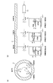
次に、管の超音波検査装置の検査結果からの腐食態様の推定方法について、図3を用いて説明する。
被検査管2の腐食は、図3(a)に示すように、腐食していない健全部に対し、管の内面が腐食する内面腐食と、管の外面が腐食する外面腐食の態様がある。肉厚Tの測定値だけでは、内面腐食と外面腐食を識別することはできないので、水距離(内径)Rの測定値を考慮して、これらを識別する。
健全部の場合には、図3(b)の左側部に示す探傷画面のような超音波の発信波(T)とエコー波(S1波)とエコー波(B1波)となる。
これに対し、内面腐食の場合には、図3(b)の中央部に示す探傷画面のような超音波の発信波(T)とエコー波(S1波)とエコー波(B1波)となる。水距離(内径)が健全部より長く、肉厚が健全部より短くなる。
また、外面腐食の場合には、図3(b)の右側尾部に示す探傷画面のような超音波の発信波(T)とエコー波(S1波)とエコー波(B1波)となる。水距離(内径)が健全部とほぼ同じであり、肉厚が健全部より短くなる。
被検査管2を正しく検査するためには、超音波パルスを被検査管2の管壁に垂直に入射する必要がある。そのためには、検査探触部12を、被検査管2の中心に位置し、その管軸方向に平行な状態で保持する必要がある。
本実施形態による管の超音波検査装置10では、図4(a)に示すように、検査探触部12を第1センタリング部30により保持し、検査探触部12近傍のフレキシブルホース13を第2センタリング部32により保持する。第1センタリング部30と第2センタリング部32とにより、検査探触部12を被検査管2の中心位置で保持するセンタリング治具であるセンタリング部材を構成する。
センタリング治具で検査探触部12を被検査管2の中心位置で保持することにより、ミラー16の回転中心を被検査管2の中心軸に合わせることができ、ミラー16の回転中心から被検査管2の内壁までの距離を一定に保つことができる。
本実施形態では、図4(a)に示すように、検査探触部12近傍のフレキシブルホース13の周囲にコイルバネを設け、元の直管形状に復元し易い構造の柔軟部13′としている。検査探触部12に接続されたフレキシブルホース13の柔軟部13′は、柔軟に変形可能である。
第1センタリング部30は、検査探触部12のミラー16側の前部を保持する。第2センタリング部32は、検査探触部12近傍のフレキシブルホース13の柔軟部13′を保持する。
第1センタリング部30と第2センタリング部32により検査探触部12及びフレキシブルホース13の柔軟部13′を保持することにより、検査探触部12を、被検査管2の中心に位置し、その管軸方向に平行な状態で保持することができる。
検査探触部12に柔軟なフレキシブルホース13が接続されているので、検査探触部12を被検査管2に挿入すると、被検査管2のベント部で、フレキシブルホース13が曲がり、検査探触部12をスムーズに通過させることができる。
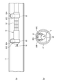
第1センタリング部30の構造について、図4(b)を用いて説明する。第1センタリング部30と第2センタリング部32の構造は同じであるので、第2センタリング部32の構造の説明は省略する。
第1センタリング部30は、検査探触部12のミラー16側の前部を、被検査管2の中心に位置するように保持する。第1センタリング部30には、円柱形状の検査探触部12の大きさに適合した孔が形成されており、その孔の内周が、円柱形状の検査探触部12を保持するための保持部31として機能している。
第1センタリング部30の外周の一側、図4(b)の上側に、被検査管2の管壁を吸引する磁石30Aが設けられている。磁石30Aの両側には、被検査管2の管壁を走行する走行車輪30B、30Cが設けられている。走行車輪30B、30Cは回転自在に取り付けられている。第1センタリング部30の外周とは、管の軸方向に垂直な平面での外周を意味する。
磁石30Aは被検査管2の管壁を吸引し、検査探触部12を被検査管2の一方の側に引き寄せるが、管壁に吸着しないようにする。磁石30A、走行車輪30B、30Cの大きさや取り付け位置を調整して、第1センタリング部30の走行車輪30B、30Cによる走行の際に、磁石30Aと管壁を所定距離離間させることで、磁石30Aが管壁に吸着しないようにする。これにより、検査探触部12を被検査管2にスムーズに挿入することができる。
また、第1センタリング部30の外周の他側、図4(b)の下側を、上側に比べて短くなるように外周形状を設計している。すなわち、第1センタリング部30の保持部31から図4(b)の下側の外周までの長さを、保持部31から図4(b)の上側の外周までの長さよりも短くなるように形成している。第2センタリング部32の外周の他側も同様に一側に比べて短くなるように外周形状を設計している。
このように外周形状を設計することにより、被検査管2の曲がり部分においても、第1センタリング部30と第2センタリング部32の外周の他側が被検査管2の内壁に衝突することなく、スムーズに通過することができる。
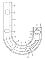
図5に示すように、フレキシブルホース13を用いて検査探触部12を被検査管2内に挿入する。フレキシブルホース13には一定距離毎に太径部13aを設けられている。作業者がフレキシブルホース13を用いて検査探触部12を挿入するときに、太径部13aの数をカウントすることにより、被検査管2への挿入長さがわかる。
本実施形態による管の超音波検査装置10の検査探触部12を被検査管2に挿入するときには、図5に示すように、被検査管2のベント部を通過するときにも、第1センタリング部30、第2センタリング部32の外周が被検査管2の管壁に衝突することなく、スムーズに通過する。
以上の通り、本実施形態による管の超音波検査装置では、磁石30A、32Aにより被検査管2の管壁を吸引し、検査探触部12を被検査管2の一方の側に引き寄せるようにしたので、検査探触部12を被検査管2内の半径方向の位置を一定に保つことができる。
次に、本実施形態による管の超音波検査装置を用いた管の超音波検査方法である超音波探傷法について説明する。
被検査管2を検査する場合には、第1センタリング部30、第2センタリング部32の磁石30A、32Aにより、被検査管2の管壁を吸引しながら、走行車輪30B、30C、32B、32Cにより検査探触部12を被検査管2内で走行させて、被検査管2内に挿入する。これにより検査探触部12を被検査管2の中心位置に保持しながら、探触子14から超音波を発信し、超音波をミラー16により反射して被検査管2の管壁に垂直に入射し、被検査管2からのエコー波を探触子14で受信する。発信した超音波とエコー波をデータ処理部40によりデータ処理して、被検査管2を検査する。
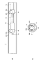
本実施形態による管の超音波検査装置では、センタリング部材を交換できるように設計し、被検査管の様々な管径に対応したセンタリング部材を用意しておくことが望ましい。これにより様々な管径の被検査管に対応することができる。
例えば、図6に示すように、被検査管2の管径がより大きい場合には、その管径に基づいて外周の径がより大きい第1センタリング部30、第2センタリング部32を用いる。第1センタリング部30は、その外周の径がより大きく設計されている。磁石30A、走行車輪30B、30Cの大きさや取り付け位置を調整して、第1センタリング部30の走行車輪30B、30Cによる走行の際に、磁石30Aが管壁に吸着しないようにする。
これにより、被検査管の管径が異なる場合でも、検査探触部12を、被検査管2の中心に位置し、その管軸方向に平行な状態で保持することができる。
本発明は上記実施形態に限らず種々の変形が可能である。
例えば、上記実施形態では、センタリング部材を2つのセンタリング部により構成し、これら2つのセンタリング部により検査探触部及びその近傍を保持したが、ひとつのセンタリング部により検査探触部及びその近傍を保持してもよいし、3つ以上のセンタリング部により検査探触部及びその近傍を保持してもよい。また、上記実施形態では、センタリング部材を2つの同じ構成のセンタリング部により構成したが、各センタリング部の構成が同じ構成でなくてもよい。
また、上記実施形態では、センタリング部の外周の一側に、ひとつの磁石と2つの走行車輪を設けたが、そのような構成に限らない。例えば、3つの走行車輪を設け、走行車輪の間に2つの磁石を設けるようにしてもよい。
2…被検査管
10…管の超音波検査装置
12…検査探触部
13…フレキシブルホース
13′…柔軟部
13a…太径部
14…探触子
15…ケーブル
16…ミラー
18…ミラー保持部
20…ハウジング
22…ベアリング
24…タービン
30…第1センタリング部
31…保持部
30A…磁石
30B、30C…走行車輪
32…第2センタリング部
32A…磁石
32B、32C…走行車輪
40…超音波探傷器送受信装置
40A…水距離測定用探傷器
40B…肉厚測定用探傷器
42…アナログ/デジタル変換器
44…PC
10…管の超音波検査装置
12…検査探触部
13…フレキシブルホース
13′…柔軟部
13a…太径部
14…探触子
15…ケーブル
16…ミラー
18…ミラー保持部
20…ハウジング
22…ベアリング
24…タービン
30…第1センタリング部
31…保持部
30A…磁石
30B、30C…走行車輪
32…第2センタリング部
32A…磁石
32B、32C…走行車輪
40…超音波探傷器送受信装置
40A…水距離測定用探傷器
40B…肉厚測定用探傷器
42…アナログ/デジタル変換器
44…PC
Claims (8)
- 超音波を発信し、超音波のエコー波を受信する探触子と、前記探触子から発信された超音波を被検査管へ反射し、前記被検査管からのエコー波を前記探触子へ反射するミラーとが収納された検査探触部と、
前記探触子が発信する超音波と前記探触子が受信するエコー波に基づいて前記被検査管の検査データを処理するデータ処理部と、
前記検査探触部を保持する保持部を有し、前記被検査管の内管壁を吸引する磁石と、前記被検査管の管壁を走行する走行車輪とが外周の一側に設けられたセンタリング部材と
を有することを特徴とする管の超音波検査装置。 - 請求項1記載の管の超音波検査装置において、
前記探触子から前記ミラーへの超音波の伝達軸を中心としてミラーを回転させる回転機構を更に有し、
前記センタリング部材の前記保持部により、前記伝達軸が前記被検査管の中心軸に平行となるように前記検査探触部を保持する
ことを特徴とする管の超音波検査装置。 - 請求項1又は3記載の管の超音波検査装置において、
前記センタリング部材は、
前記被検査管の管壁を吸引する磁石と、前記被検査管の管壁を走行する走行車輪とが外周の一側に設けられた第1センタリング部と、
前記被検査管の管壁を吸引する磁石と、前記被検査管の管壁を走行する走行車輪とが外周の一側に設けられた第2センタリング部と
を有することを特徴とする管の超音波検査装置。 - 請求項2又は3記載の管の超音波検査装置において、
前記センタリング部材の外周の他側から前記伝達軸までの長さが、前記センタリング部材の外周の一側から前記伝達軸までの長さよりも短い
ことを特徴とする管の超音波検査装置。 - 請求項3又は4記載の管の超音波検査装置において、
前記第1センタリング部により保持される部分と前記第2センタリング部により保持される部分の間の前記検査探触部の少なくとも一部分が変形可能である
ことを特徴とする管の超音波検査装置。 - 請求項1乃至5のいずれか1項に記載の管の超音波検査装置を用いた管の超音波検査方法であって、
前記磁石により前記被検査管の管壁を吸引しながら、前記走行車輪により前記検査探触部を前記被検査管内で走行させ、
前記被検査管の検査データを前記データ処理部で処理する
ことを特徴とする管の超音波検査方法。 - 請求項6記載の管の超音波検査方法において、
前記被検査管の管内径が一定でない
ことを特徴とする管の超音波検査方法。 - 請求項6記載の管の超音波検査方法において、
前記被検査管が曲がっている
ことを特徴とする管の超音波検査方法。
Priority Applications (1)
| Application Number | Priority Date | Filing Date | Title |
|---|---|---|---|
| JP2013504755A JP5829674B2 (ja) | 2011-03-14 | 2012-03-14 | 管の超音波検査装置及び管の超音波検査方法 |
Applications Claiming Priority (2)
| Application Number | Priority Date | Filing Date | Title |
|---|---|---|---|
| JP2011-055285 | 2011-03-14 | ||
| JP2011055285 | 2011-03-14 |
Publications (1)
| Publication Number | Publication Date |
|---|---|
| WO2012124731A1 true WO2012124731A1 (ja) | 2012-09-20 |
Family
ID=46830796
Family Applications (1)
| Application Number | Title | Priority Date | Filing Date |
|---|---|---|---|
| PCT/JP2012/056556 WO2012124731A1 (ja) | 2011-03-14 | 2012-03-14 | 管の超音波検査装置及び管の超音波検査方法 |
Country Status (2)
| Country | Link |
|---|---|
| JP (1) | JP5829674B2 (ja) |
| WO (1) | WO2012124731A1 (ja) |
Cited By (5)
| Publication number | Priority date | Publication date | Assignee | Title |
|---|---|---|---|---|
| JP2015169548A (ja) * | 2014-03-07 | 2015-09-28 | 積水化学工業株式会社 | 超音波検査装置および超音波検査方法 |
| EP2916069A4 (en) * | 2013-07-02 | 2016-02-17 | Mitsubishi Materials Corp | METHOD FOR MEASURING THE THICKNESS OF A BOILER WATER TUBE |
| KR101659483B1 (ko) * | 2015-04-15 | 2016-09-23 | 주식회사 한국공업엔지니어링 | 열교환기의 iris 검사를 위한 장치 |
| KR101864662B1 (ko) * | 2017-04-28 | 2018-06-05 | 유근민 | 초음파 탐촉자용 이동 로봇 |
| KR102387924B1 (ko) * | 2021-09-14 | 2022-04-19 | 주식회사 지스콥 | 튜브 휠을 포함한 비파괴 검사용 자동 스캐너 차체의 바퀴 구조 |
Citations (3)
| Publication number | Priority date | Publication date | Assignee | Title |
|---|---|---|---|---|
| JPS59143955A (ja) * | 1983-02-08 | 1984-08-17 | Babcock Hitachi Kk | 探触子調芯移動装置 |
| JP2001226707A (ja) * | 1999-12-10 | 2001-08-21 | Sumitomo Metal Ind Ltd | ステーブクーラの検査方法、同装置、パイプをコアとする多層構造物の検査方法及び同装置 |
| JP2004144710A (ja) * | 2002-10-28 | 2004-05-20 | Shin Nippon Hihakai Kensa Kk | 大径管の板厚測定システム |
-
2012
- 2012-03-14 JP JP2013504755A patent/JP5829674B2/ja active Active
- 2012-03-14 WO PCT/JP2012/056556 patent/WO2012124731A1/ja active Application Filing
Patent Citations (3)
| Publication number | Priority date | Publication date | Assignee | Title |
|---|---|---|---|---|
| JPS59143955A (ja) * | 1983-02-08 | 1984-08-17 | Babcock Hitachi Kk | 探触子調芯移動装置 |
| JP2001226707A (ja) * | 1999-12-10 | 2001-08-21 | Sumitomo Metal Ind Ltd | ステーブクーラの検査方法、同装置、パイプをコアとする多層構造物の検査方法及び同装置 |
| JP2004144710A (ja) * | 2002-10-28 | 2004-05-20 | Shin Nippon Hihakai Kensa Kk | 大径管の板厚測定システム |
Cited By (5)
| Publication number | Priority date | Publication date | Assignee | Title |
|---|---|---|---|---|
| EP2916069A4 (en) * | 2013-07-02 | 2016-02-17 | Mitsubishi Materials Corp | METHOD FOR MEASURING THE THICKNESS OF A BOILER WATER TUBE |
| JP2015169548A (ja) * | 2014-03-07 | 2015-09-28 | 積水化学工業株式会社 | 超音波検査装置および超音波検査方法 |
| KR101659483B1 (ko) * | 2015-04-15 | 2016-09-23 | 주식회사 한국공업엔지니어링 | 열교환기의 iris 검사를 위한 장치 |
| KR101864662B1 (ko) * | 2017-04-28 | 2018-06-05 | 유근민 | 초음파 탐촉자용 이동 로봇 |
| KR102387924B1 (ko) * | 2021-09-14 | 2022-04-19 | 주식회사 지스콥 | 튜브 휠을 포함한 비파괴 검사용 자동 스캐너 차체의 바퀴 구조 |
Also Published As
| Publication number | Publication date |
|---|---|
| JPWO2012124731A1 (ja) | 2014-07-24 |
| JP5829674B2 (ja) | 2015-12-09 |
Similar Documents
| Publication | Publication Date | Title |
|---|---|---|
| JP5829674B2 (ja) | 管の超音波検査装置及び管の超音波検査方法 | |
| RU2529655C2 (ru) | Прибор контроля трубопровода с двойной спиральной матрицей электромагнитоакустических датчиков | |
| CA2941509C (en) | Pipeline inspection tool | |
| JP2007187593A (ja) | 配管検査装置及び配管検査方法 | |
| KR101796159B1 (ko) | 자성이물질제거가 용이한 결함탐상장치 | |
| Sadek | NDE technologies for the examination of heat exchangers and boiler tubes-principles, advantages and limitations | |
| CN102460143A (zh) | 用于测量管内侧沉积物的装置和方法 | |
| US10048225B2 (en) | Apparatus and method for inspection of tubes in a boiler | |
| JP2015525357A (ja) | 渦電流探傷プローブ | |
| RU2176082C1 (ru) | Внутритрубный магнитный дефектоскоп | |
| US20180164255A1 (en) | Adjustable wide bandwidth guidewave (gw) probe for tube and pipe inspection systems | |
| JP4772830B2 (ja) | チューブの超音波肉厚測定装置 | |
| JP5297791B2 (ja) | 非破壊検査装置及び非破壊検査方法 | |
| US11162919B2 (en) | Ultrasonic based internal inspection of tubes | |
| KR100768390B1 (ko) | 유도초음파를 이용한 열교환기 검사장치 | |
| JP2009229451A (ja) | 管内挿入式超音波探傷検査装置 | |
| JP4363699B2 (ja) | 浸炭層の検出方法及びその厚さの測定方法 | |
| KR102341795B1 (ko) | 파이프의 내부 라이닝 검사장치 | |
| KR20220042220A (ko) | 관 부재의 검사 시스템 및 관 부재의 검사 방법 | |
| RU131866U1 (ru) | Внутритрубный многоканальный профилемер | |
| CN204154321U (zh) | 一种应用于流体超声测量的结构装置 | |
| US20170010179A1 (en) | Adjustable wide bandwidth guidedwave (gw) probe for tube and pipe inspection system | |
| JP2001349846A (ja) | 管内検査装置の円周方向角度検出方法 | |
| RU215140U1 (ru) | Блок датчиков дефектоскопа | |
| CN218099000U (zh) | 一种小径管涡流检测探头 |
Legal Events
| Date | Code | Title | Description |
|---|---|---|---|
| 121 | Ep: the epo has been informed by wipo that ep was designated in this application |
Ref document number: 12757841 Country of ref document: EP Kind code of ref document: A1 |
|
| NENP | Non-entry into the national phase |
Ref country code: DE |
|
| ENP | Entry into the national phase |
Ref document number: 2013504755 Country of ref document: JP Kind code of ref document: A |
|
| 122 | Ep: pct application non-entry in european phase |
Ref document number: 12757841 Country of ref document: EP Kind code of ref document: A1 |