WO2012124574A1 - 放電ロール装置 - Google Patents
放電ロール装置 Download PDFInfo
- Publication number
- WO2012124574A1 WO2012124574A1 PCT/JP2012/055858 JP2012055858W WO2012124574A1 WO 2012124574 A1 WO2012124574 A1 WO 2012124574A1 JP 2012055858 W JP2012055858 W JP 2012055858W WO 2012124574 A1 WO2012124574 A1 WO 2012124574A1
- Authority
- WO
- WIPO (PCT)
- Prior art keywords
- discharge roll
- side terminal
- brush
- bearing
- discharge
- Prior art date
- Legal status (The legal status is an assumption and is not a legal conclusion. Google has not performed a legal analysis and makes no representation as to the accuracy of the status listed.)
- Ceased
Links
Images

Classifications
-
- F—MECHANICAL ENGINEERING; LIGHTING; HEATING; WEAPONS; BLASTING
- F16—ENGINEERING ELEMENTS AND UNITS; GENERAL MEASURES FOR PRODUCING AND MAINTAINING EFFECTIVE FUNCTIONING OF MACHINES OR INSTALLATIONS; THERMAL INSULATION IN GENERAL
- F16C—SHAFTS; FLEXIBLE SHAFTS; ELEMENTS OR CRANKSHAFT MECHANISMS; ROTARY BODIES OTHER THAN GEARING ELEMENTS; BEARINGS
- F16C13/00—Rolls, drums, discs, or the like; Bearings or mountings therefor
- F16C13/02—Bearings
- F16C13/022—Bearings supporting a hollow roll mantle rotating with respect to a yoke or axle
-
- B—PERFORMING OPERATIONS; TRANSPORTING
- B29—WORKING OF PLASTICS; WORKING OF SUBSTANCES IN A PLASTIC STATE IN GENERAL
- B29C—SHAPING OR JOINING OF PLASTICS; SHAPING OF MATERIAL IN A PLASTIC STATE, NOT OTHERWISE PROVIDED FOR; AFTER-TREATMENT OF THE SHAPED PRODUCTS, e.g. REPAIRING
- B29C59/00—Surface shaping of articles, e.g. embossing; Apparatus therefor
- B29C59/10—Surface shaping of articles, e.g. embossing; Apparatus therefor by electric discharge treatment
Definitions
- the present invention relates to a discharge roll apparatus, and more particularly to a discharge roll apparatus that prevents electrical corrosion of a bearing and ensures safety.
- An object of the present invention is to provide a discharge roll device that can prevent the electrolytic corrosion of a bearing more reliably and ensure safety.
- a grounded mount A rotating discharge roll supported via a bearing on the mount; A brush that is supported in an insulating state on the gantry and is in sliding contact with the surface of the rotary discharge roll or the shaft of the rotary discharge roll; A discharge electrode disposed opposite to the surface of the rotary discharge roll with a gap therebetween; A high frequency transformer having a secondary winding to which a ground side terminal and a high voltage side terminal are connected; A discharge roll device comprising: The ground side terminal is connected to the brush and grounded via an inductor, The discharge roll apparatus, wherein the high-voltage side terminal is connected to the discharge electrode.
- the inductor when viewed from the secondary winding of the high-frequency transformer, the inductor does not intervene in the circuit passing through the brush, but the inductor passes through the circuit passing through the bearing. High-frequency current flows through the circuit passing through, and almost no high-frequency current flows through the circuit passing through the high-impedance bearing. For this reason, the electric corrosion of a bearing can be prevented more reliably.
- the pedestal that is easy to touch is grounded, and the ground side terminal of the secondary winding of the high-frequency transformer is also grounded in a DC manner, so that safety is also maintained.
- composition explanatory drawing which shows the discharge roll apparatus which concerns on 1st Embodiment. It is structure explanatory drawing which shows the discharge roll apparatus which concerns on 2nd Embodiment.
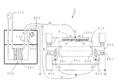
- FIG. 1 is a configuration explanatory view showing a discharge roll device 1 according to the first embodiment.
- the discharge roll apparatus 1 includes a rotary discharge roll 311, a grounded metal mount 401, a metal bearing 331 for rotatably supporting the rotary discharge roll 311 on the mount 401, and the rotary discharge roll 311.
- a brush 321 slidably in contact with the surface of the metal shaft 312, an insulator holder 322 for insulating and supporting the brush 321 on the mount 401, and a surface of the rotary discharge roll 311 with a gap therebetween are disposed.
- the discharge electrode 301, the high-frequency power supply 100, the boosting high-frequency transformer 200, and the high-frequency current limiting inductor 221 are provided.
- the inductance of the inductor 221 is several mH, for example.
- a high-voltage side terminal 211 of the secondary winding 201 of the high-frequency transformer 200 is connected to the discharge electrode 301.
- the ground-side terminal 212 of the secondary winding 201 of the high-frequency transformer 200 is connected to the brush 321 and is connected to the mount 401 via the inductor 221.
- Corona discharge is generated in the gap between the rotary discharge roll 311 and the discharge electrode 301, and the polymer film F passing through the gap is subjected to corona discharge treatment.
- the circuit of high-voltage side terminal 211 ⁇ discharge electrode 301 ⁇ rotary discharge roll 311 ⁇ shaft 312 ⁇ bearing 331 ⁇ mounting base 401 ⁇ inductor 221 ⁇ ground side terminal 212 is connected to the ground side terminal from the shaft 312 because the inductor 221 is interposed. Impedance up to 212 is high.
- a high-frequency (for example, 10 kHz to several tens of kHz) discharge current flows through a circuit that passes through a brush 321 having a low impedance, and hardly flows through a circuit that passes through a bearing 331 having a high impedance. For this reason, the electrolytic corrosion of the bearing 331 is prevented.
- the discharge roll apparatus 1 of 1st Embodiment the following effect is acquired. (1) Since high-frequency current hardly flows through the bearing 331, electrolytic corrosion of the bearing 331 can be prevented. (2) Since the base 401 that is easy to touch is grounded, and the ground side terminal 212 of the secondary winding 201 of the high-frequency transformer 200 is also grounded in a direct current manner, the safety is high.
- FIG. 2 is a configuration explanatory view showing the discharge roll device 2 according to the second embodiment.
- This discharge roll device 2 is obtained by grounding the ground side terminal 212 of the secondary winding 201 of the high-frequency transformer 200 via an inductor 221, and the other configuration is the same as that of the discharge roll device 1 according to the first embodiment. is there.
- the brush 321 may be in sliding contact with the surface of the rotary discharge roll 311 instead of the configuration in which the brush 321 is in contact with the surface of the shaft 312.
- the present invention is not limited to the above-described embodiment, and can be appropriately modified and improved.
- the material, shape, dimension, numerical value, form, number, arrangement location, and the like of each component in the above-described embodiment are arbitrary and are not limited as long as the present invention can be achieved.
- the discharge roll device of the present invention since high-frequency current hardly flows in the circuit passing through the bearing, it is possible to prevent electrolytic corrosion of the bearing.
- the pedestal that is easy to touch is grounded, and safety is maintained.
- the discharge roll apparatus of the present invention can be used, for example, in a corona discharge treatment apparatus for polymer films.
Landscapes
- Engineering & Computer Science (AREA)
- General Engineering & Computer Science (AREA)
- Mechanical Engineering (AREA)
- Rolls And Other Rotary Bodies (AREA)
- Motor Or Generator Frames (AREA)
- Elimination Of Static Electricity (AREA)
Abstract
アースした架台上にベアリングを介して回転放電ロールを支持すると共に前記回転放電ロールのシャフトの表面に摺接しうるブラシを前記架台に絶縁して支持し、前記回転放電ロールの表面に空隙を挟んで放電電極を対向配置し、高周波トランスの二次巻線のアース側端子と前記ブラシとを接続し、前記高周波トランスの二次巻線の高圧側端子と前記放電電極とを接続し、前記アース側端子をインダクタを介してアースする。
Description
この発明は、放電ロール装置に関し、さらに詳しくは、ベアリングの電食を防止すると共に安全性を確保した放電ロール装置に関する。
従来、架台上にベアリングを介して回転ロールを支持すると共に回転ロールの表面に摺接しうるブラシを架台に通電可能に設置し、架台と回転ロールとを同電位にすることにより、ベアリングに電流が流れないようにしたベアリングの電食防止装置が知られている(例えば特許文献1参照。)。
上記従来の電食防止装置では、電流がブラシを通る回路に流れ、ベアリングを通る回路には流れないとしている。
しかし、通常のベアリングは鋼製であり、ベアリングを通る回路の抵抗値も低いため、実際にはベアリングを通る回路にも電流が流れ、ベアリングの電食を起こす可能性があった。
そこで、この発明の目的は、より確実にベアリングの電食を防止しうると共に安全性を確保した放電ロール装置を提供することにある。
しかし、通常のベアリングは鋼製であり、ベアリングを通る回路の抵抗値も低いため、実際にはベアリングを通る回路にも電流が流れ、ベアリングの電食を起こす可能性があった。
そこで、この発明の目的は、より確実にベアリングの電食を防止しうると共に安全性を確保した放電ロール装置を提供することにある。
本発明の上記目的は、下記構成により達成される。
(1)アースされた架台と、
前記架台上にベアリングを介して支持された回転放電ロールと、
前記架台上に絶縁状態に支持されて前記回転放電ロールまたは前記回転放電ロールのシャフトの表面に摺接するブラシと、
前記回転放電ロールの表面に空隙を挟んで対向配置された放電電極と、
アース側端子及び高圧側端子が接続された二次巻線を有する高周波トランスと、
を備えた放電ロール装置であって、
前記アース側端子が前記ブラシに接続されると共にインダクタを介してアースされ、
前記高圧側端子が前記放電電極に接続されたことを特徴とする放電ロール装置。
(1)アースされた架台と、
前記架台上にベアリングを介して支持された回転放電ロールと、
前記架台上に絶縁状態に支持されて前記回転放電ロールまたは前記回転放電ロールのシャフトの表面に摺接するブラシと、
前記回転放電ロールの表面に空隙を挟んで対向配置された放電電極と、
アース側端子及び高圧側端子が接続された二次巻線を有する高周波トランスと、
を備えた放電ロール装置であって、
前記アース側端子が前記ブラシに接続されると共にインダクタを介してアースされ、
前記高圧側端子が前記放電電極に接続されたことを特徴とする放電ロール装置。
上記(1)の放電ロール装置では、高周波トランスの二次巻線から見たとき、ブラシを通る回路にはインダクタが介在しないが、ベアリングを通る回路にはインダクタが介在するため、インピーダンスの低いブラシを通る回路に高周波電流が流れ、インピーダンスの高いベアリングを通る回路には高周波電流がほとんど流れなくなる。このため、より確実にベアリングの電食を防止できる。他方、人が触れやすい架台はアースされており、高周波トランスの二次巻線のアース側端子も直流的にアースされているため、安全性も保たれる。
以下、図に示す実施形態により本発明をさらに詳細に説明する。なお、本発明は下記実施形態に限定されるものではない。
[第1実施形態]
図1は、第1実施形態に係る放電ロール装置1を示す構成説明図である。
この放電ロール装置1は、回転放電ロール311と、アースした金属製の架台401と、回転放電ロール311を架台401上に回転可能に支持するための金属製のベアリング331と、回転放電ロール311の金属製のシャフト312の表面に摺接しうるブラシ321と、架台401にブラシ321を絶縁して支持するための絶縁物製のホルダ322と、回転放電ロール311の表面に空隙を挟んで対向配置された放電電極301と、高周波電源100と、昇圧用の高周波トランス200と、高周波電流制限用のインダクタ221とを具備している。
図1は、第1実施形態に係る放電ロール装置1を示す構成説明図である。
この放電ロール装置1は、回転放電ロール311と、アースした金属製の架台401と、回転放電ロール311を架台401上に回転可能に支持するための金属製のベアリング331と、回転放電ロール311の金属製のシャフト312の表面に摺接しうるブラシ321と、架台401にブラシ321を絶縁して支持するための絶縁物製のホルダ322と、回転放電ロール311の表面に空隙を挟んで対向配置された放電電極301と、高周波電源100と、昇圧用の高周波トランス200と、高周波電流制限用のインダクタ221とを具備している。
インダクタ221のインダクタンスは、例えば数mHである。
高周波トランス200の二次巻線201の高圧側端子211は、放電電極301に接続されている。
高周波トランス200の二次巻線201のアース側端子212は、ブラシ321に接続されると共に、インダクタ221を介して架台401に接続されている。
高周波トランス200の二次巻線201のアース側端子212は、ブラシ321に接続されると共に、インダクタ221を介して架台401に接続されている。
コロナ放電が回転放電ロール311と放電電極301の間の空隙に発生し、この空隙を通過する高分子フィルムFがコロナ放電処理される。
高周波トランス200の二次巻線201から見たとき、高圧側端子211→放電電極301→回転放電ロール311→シャフト312→ブラシ321→アース側端子212となる回路は、シャフト312からアース側端子212までのインピーダンスが低い。他方、高圧側端子211→放電電極301→回転放電ロール311→シャフト312→ベアリング331→架台401→インダクタ221→アース側端子212となる回路は、インダクタ221が介在するため、シャフト312からアース側端子212までのインピーダンスが高い。そこで、高周波(例えば10kHz~数10kHz)の放電電流は、インピーダンスの低いブラシ321を通る回路に流れ、インピーダンスの高いベアリング331を通る回路にはほとんど流れなくなる。このため、ベアリング331の電食が防止される。
第1実施形態の放電ロール装置1によれば次の効果が得られる。
(1)高周波電流がベアリング331にはほとんど流れなくなるため、ベアリング331の電食を防止できる。
(2)人が触れやすい架台401はアースされており、高周波トランス200の二次巻線201のアース側端子212も直流的にアースされているため、安全性も高い。
(1)高周波電流がベアリング331にはほとんど流れなくなるため、ベアリング331の電食を防止できる。
(2)人が触れやすい架台401はアースされており、高周波トランス200の二次巻線201のアース側端子212も直流的にアースされているため、安全性も高い。
[第2実施形態]
図2は、第2実施形態に係る放電ロール装置2を示す構成説明図である。
この放電ロール装置2は、インダクタ221を介して高周波トランス200の二次巻線201のアース側端子212をアースしたもので、これ以外の構成は第1実施形態に係る放電ロール装置1と同様である。
図2は、第2実施形態に係る放電ロール装置2を示す構成説明図である。
この放電ロール装置2は、インダクタ221を介して高周波トランス200の二次巻線201のアース側端子212をアースしたもので、これ以外の構成は第1実施形態に係る放電ロール装置1と同様である。
[第3実施形態]
上述した第1実施形態及び第2実施形態において、シャフト312の表面にブラシ321が接する構成に代えて、回転放電ロール311の表面にブラシ321が摺接するようにしてもよい。
上述した第1実施形態及び第2実施形態において、シャフト312の表面にブラシ321が接する構成に代えて、回転放電ロール311の表面にブラシ321が摺接するようにしてもよい。
本発明は、上述した実施形態に限定されるものではなく、適宜、変形、改良等が自在である。その他、上述した実施形態における各構成要素の材質、形状、寸法、数値、形態、数、配置場所、等は本発明を達成できるものであれば任意であり、限定されない。
本発明を詳細にまた特定の実施態様を参照して説明したが、本発明の精神と範囲を逸脱することなく様々な変更や修正を加えることができることは当業者にとって明らかである。
本出願は、2011年3月11日出願の日本特許出願(特願2011-053904)に基づくものであり、その内容はここに参照として取り込まれる。
本発明の放電ロール装置によれば、ベアリングを通る回路には高周波電流がほとんど流れなくなるため、ベアリングの電食を防止できる。また、人が触れやすい架台はアースされており、安全性も保たれる。
本発明の放電ロール装置は、例えば高分子フィルムのコロナ放電処理装置に利用できる。
1,2 放電ロール装置
200 高周波トランス
201 二次巻線
211 高圧側端子
212 アース側端子
221 インダクタ
311 回転放電ロール
312 シャフト
321 ブラシ
322 ホルダ
331 ベアリング
401 架台
F 高分子フィルム
200 高周波トランス
201 二次巻線
211 高圧側端子
212 アース側端子
221 インダクタ
311 回転放電ロール
312 シャフト
321 ブラシ
322 ホルダ
331 ベアリング
401 架台
F 高分子フィルム
Claims (1)
- アースされた架台と、
前記架台上にベアリングを介して支持された回転放電ロールと、
前記架台上に絶縁状態に支持されて前記回転放電ロールまたは前記回転放電ロールのシャフトの表面に摺接するブラシと、
前記回転放電ロールの表面に空隙を挟んで対向配置された放電電極と、
アース側端子及び高圧側端子が接続された二次巻線を有する高周波トランスと、
を備えた放電ロール装置であって、
前記アース側端子が前記ブラシに接続されると共にインダクタを介してアースされ、
前記高圧側端子が前記放電電極に接続されたことを特徴とする放電ロール装置。
Applications Claiming Priority (2)
| Application Number | Priority Date | Filing Date | Title |
|---|---|---|---|
| JP2011053904A JP2012191776A (ja) | 2011-03-11 | 2011-03-11 | 放電ロール装置 |
| JP2011-053904 | 2011-03-11 |
Publications (1)
| Publication Number | Publication Date |
|---|---|
| WO2012124574A1 true WO2012124574A1 (ja) | 2012-09-20 |
Family
ID=46830647
Family Applications (1)
| Application Number | Title | Priority Date | Filing Date |
|---|---|---|---|
| PCT/JP2012/055858 Ceased WO2012124574A1 (ja) | 2011-03-11 | 2012-03-07 | 放電ロール装置 |
Country Status (2)
| Country | Link |
|---|---|
| JP (1) | JP2012191776A (ja) |
| WO (1) | WO2012124574A1 (ja) |
Families Citing this family (2)
| Publication number | Priority date | Publication date | Assignee | Title |
|---|---|---|---|---|
| JP7315498B2 (ja) * | 2020-02-27 | 2023-07-26 | 株式会社日本製鋼所 | コロナ放電処理の試験方法およびその試験装置 |
| JP7738495B2 (ja) * | 2022-02-04 | 2025-09-12 | 株式会社日本製鋼所 | コロナ放電処理装置、コロナ放電処理方法、およびフィルム製造システム、並びにフィルム製造方法 |
Citations (5)
| Publication number | Priority date | Publication date | Assignee | Title |
|---|---|---|---|---|
| JPS5521313A (en) * | 1978-07-26 | 1980-02-15 | Mitsubishi Electric Corp | Ground apparatus for elevator hoist |
| JPH0544302U (ja) * | 1991-11-13 | 1993-06-15 | 住友金属工業株式会社 | 電食防止装置 |
| JPH07184342A (ja) * | 1991-08-21 | 1995-07-21 | Westinghouse Electric Corp <We> | 回転軸自動接地装置 |
| JPH11158670A (ja) * | 1997-11-28 | 1999-06-15 | Mitsubishi Shindoh Co Ltd | 金属基材の製造方法とコロナ放電脱脂処理方法および脱脂金属基材の製造装置 |
| JP2011036063A (ja) * | 2009-08-04 | 2011-02-17 | Japan Steel Works Ltd:The | コロナ放電処理装置用の共振型pamインバータ電力供給装置 |
-
2011
- 2011-03-11 JP JP2011053904A patent/JP2012191776A/ja not_active Withdrawn
-
2012
- 2012-03-07 WO PCT/JP2012/055858 patent/WO2012124574A1/ja not_active Ceased
Patent Citations (5)
| Publication number | Priority date | Publication date | Assignee | Title |
|---|---|---|---|---|
| JPS5521313A (en) * | 1978-07-26 | 1980-02-15 | Mitsubishi Electric Corp | Ground apparatus for elevator hoist |
| JPH07184342A (ja) * | 1991-08-21 | 1995-07-21 | Westinghouse Electric Corp <We> | 回転軸自動接地装置 |
| JPH0544302U (ja) * | 1991-11-13 | 1993-06-15 | 住友金属工業株式会社 | 電食防止装置 |
| JPH11158670A (ja) * | 1997-11-28 | 1999-06-15 | Mitsubishi Shindoh Co Ltd | 金属基材の製造方法とコロナ放電脱脂処理方法および脱脂金属基材の製造装置 |
| JP2011036063A (ja) * | 2009-08-04 | 2011-02-17 | Japan Steel Works Ltd:The | コロナ放電処理装置用の共振型pamインバータ電力供給装置 |
Also Published As
| Publication number | Publication date |
|---|---|
| JP2012191776A (ja) | 2012-10-04 |
Similar Documents
| Publication | Publication Date | Title |
|---|---|---|
| CN102764695B (zh) | 一种同心静电集尘装置 | |
| WO2006027946A1 (ja) | ワイヤ放電加工装置 | |
| WO2025011257A1 (zh) | 静电除尘过滤器及应用于静电除尘过滤器中的电极板 | |
| WO2012124574A1 (ja) | 放電ロール装置 | |
| JP2009232629A (ja) | サージ吸収回路 | |
| JPWO2015111236A1 (ja) | ガス絶縁電気機器 | |
| CN107683632A (zh) | 用于对尤其带状物体进行等离子处理的设备 | |
| Stone et al. | Review of stator insulation problems in medium voltage motors fed from voltage source PWM drives | |
| CN205081635U (zh) | 用于减小和/或避免电机中的有害的轴承电流的装置 | |
| CN100521434C (zh) | 一种抑制交流变压器直流偏磁电流的装置 | |
| JP2006040876A (ja) | イオン発生用セラミック電極構造物およびこれを用いたイオン発生装置 | |
| CN102593813A (zh) | 智能综合消谐装置 | |
| TWM332325U (en) | Refined structure of series surge suppression | |
| CN103675540A (zh) | 并联电容器组放电装置 | |
| RU2754539C1 (ru) | Система катодной защиты для прокатки металла | |
| JP2013220018A (ja) | 多層ブラシ | |
| JP2013078710A (ja) | 電気集塵装置 | |
| Zaninelli et al. | Fault analysis on AC/HV cable transmission lines | |
| CN203826952U (zh) | 高压设备工频耐压放电装置及放电系统 | |
| CN109521317A (zh) | 变压器铁心多点接地故障点检测方法和装置 | |
| JP4811725B2 (ja) | イオン発生器及び除電器 | |
| CN103236681B (zh) | 转子一点接地保护装置 | |
| CN100492443C (zh) | 功率因数补偿实验仪 | |
| JP2012018907A (ja) | 電機部品 | |
| Menemenlis et al. | Application of insulators to withstand switching surges in substations. I. Switching impulse insulation strength |
Legal Events
| Date | Code | Title | Description |
|---|---|---|---|
| 121 | Ep: the epo has been informed by wipo that ep was designated in this application |
Ref document number: 12758151 Country of ref document: EP Kind code of ref document: A1 |
|
| NENP | Non-entry into the national phase |
Ref country code: DE |
|
| 122 | Ep: pct application non-entry in european phase |
Ref document number: 12758151 Country of ref document: EP Kind code of ref document: A1 |