WO2012124496A1 - 画像処理装置および方法 - Google Patents
画像処理装置および方法 Download PDFInfo
- Publication number
- WO2012124496A1 WO2012124496A1 PCT/JP2012/055236 JP2012055236W WO2012124496A1 WO 2012124496 A1 WO2012124496 A1 WO 2012124496A1 JP 2012055236 W JP2012055236 W JP 2012055236W WO 2012124496 A1 WO2012124496 A1 WO 2012124496A1
- Authority
- WO
- WIPO (PCT)
- Prior art keywords
- unit
- slice
- encoding
- decoding
- image
- Prior art date
Links
Images


Classifications
-
- H—ELECTRICITY
- H04—ELECTRIC COMMUNICATION TECHNIQUE
- H04N—PICTORIAL COMMUNICATION, e.g. TELEVISION
- H04N19/00—Methods or arrangements for coding, decoding, compressing or decompressing digital video signals
- H04N19/50—Methods or arrangements for coding, decoding, compressing or decompressing digital video signals using predictive coding
- H04N19/503—Methods or arrangements for coding, decoding, compressing or decompressing digital video signals using predictive coding involving temporal prediction
- H04N19/51—Motion estimation or motion compensation
- H04N19/513—Processing of motion vectors
- H04N19/517—Processing of motion vectors by encoding
- H04N19/52—Processing of motion vectors by encoding by predictive encoding
-
- H—ELECTRICITY
- H04—ELECTRIC COMMUNICATION TECHNIQUE
- H04N—PICTORIAL COMMUNICATION, e.g. TELEVISION
- H04N19/00—Methods or arrangements for coding, decoding, compressing or decompressing digital video signals
- H04N19/10—Methods or arrangements for coding, decoding, compressing or decompressing digital video signals using adaptive coding
- H04N19/102—Methods or arrangements for coding, decoding, compressing or decompressing digital video signals using adaptive coding characterised by the element, parameter or selection affected or controlled by the adaptive coding
- H04N19/119—Adaptive subdivision aspects, e.g. subdivision of a picture into rectangular or non-rectangular coding blocks
-
- H—ELECTRICITY
- H04—ELECTRIC COMMUNICATION TECHNIQUE
- H04N—PICTORIAL COMMUNICATION, e.g. TELEVISION
- H04N19/00—Methods or arrangements for coding, decoding, compressing or decompressing digital video signals
- H04N19/10—Methods or arrangements for coding, decoding, compressing or decompressing digital video signals using adaptive coding
- H04N19/169—Methods or arrangements for coding, decoding, compressing or decompressing digital video signals using adaptive coding characterised by the coding unit, i.e. the structural portion or semantic portion of the video signal being the object or the subject of the adaptive coding
- H04N19/17—Methods or arrangements for coding, decoding, compressing or decompressing digital video signals using adaptive coding characterised by the coding unit, i.e. the structural portion or semantic portion of the video signal being the object or the subject of the adaptive coding the unit being an image region, e.g. an object
- H04N19/174—Methods or arrangements for coding, decoding, compressing or decompressing digital video signals using adaptive coding characterised by the coding unit, i.e. the structural portion or semantic portion of the video signal being the object or the subject of the adaptive coding the unit being an image region, e.g. an object the region being a slice, e.g. a line of blocks or a group of blocks
-
- H—ELECTRICITY
- H04—ELECTRIC COMMUNICATION TECHNIQUE
- H04N—PICTORIAL COMMUNICATION, e.g. TELEVISION
- H04N19/00—Methods or arrangements for coding, decoding, compressing or decompressing digital video signals
- H04N19/42—Methods or arrangements for coding, decoding, compressing or decompressing digital video signals characterised by implementation details or hardware specially adapted for video compression or decompression, e.g. dedicated software implementation
- H04N19/436—Methods or arrangements for coding, decoding, compressing or decompressing digital video signals characterised by implementation details or hardware specially adapted for video compression or decompression, e.g. dedicated software implementation using parallelised computational arrangements
-
- H—ELECTRICITY
- H04—ELECTRIC COMMUNICATION TECHNIQUE
- H04N—PICTORIAL COMMUNICATION, e.g. TELEVISION
- H04N19/00—Methods or arrangements for coding, decoding, compressing or decompressing digital video signals
- H04N19/90—Methods or arrangements for coding, decoding, compressing or decompressing digital video signals using coding techniques not provided for in groups H04N19/10-H04N19/85, e.g. fractals
- H04N19/96—Tree coding, e.g. quad-tree coding
-
- H—ELECTRICITY
- H04—ELECTRIC COMMUNICATION TECHNIQUE
- H04N—PICTORIAL COMMUNICATION, e.g. TELEVISION
- H04N19/00—Methods or arrangements for coding, decoding, compressing or decompressing digital video signals
- H04N19/60—Methods or arrangements for coding, decoding, compressing or decompressing digital video signals using transform coding
- H04N19/61—Methods or arrangements for coding, decoding, compressing or decompressing digital video signals using transform coding in combination with predictive coding
Definitions
- the present disclosure relates to an image processing apparatus and method, and more particularly, to an image processing apparatus and method capable of suppressing an increase in processing time.
- MPEG compressed by orthogonal transform such as discrete cosine transform and motion compensation is used for the purpose of efficient transmission and storage of information.
- a device that conforms to a system such as Moving (Pictures Experts Group) is becoming widespread in both information distribution at broadcast stations and information reception in general households.
- MPEG2 International Organization for Standardization
- IEC International Electrotechnical Commission
- MPEG2 was mainly intended for high-quality encoding suitable for broadcasting, but it did not support encoding methods with a lower code amount (bit rate) than MPEG1, that is, a higher compression rate. With the widespread use of mobile terminals, the need for such an encoding system is expected to increase in the future, and the MPEG4 encoding system has been standardized accordingly. Regarding the image coding system, the standard was approved as an international standard in December 1998 as ISO / IEC 14496-2.
- H.26L International Telecommunication Union Telecommunication Standardization Sector
- Q6 / 16 VCEG Video Coding Expert Group
- H.26L is known to achieve higher encoding efficiency than the conventional encoding schemes such as MPEG2 and MPEG4, although a large amount of calculation is required for encoding and decoding.
- Joint ⁇ ⁇ ⁇ ⁇ Model of Enhanced-Compression Video Coding has been implemented based on this H.26L and incorporating functions not supported by H.26L to achieve higher coding efficiency. It has been broken.
- AVC Advanced Video Coding
- the macro block size of 16 pixels x 16 pixels is optimal for large image frames such as UHD (Ultra High Definition: 4000 pixels x 2000 pixels), which are the targets of the next generation coding system. There was no fear.
- HEVC High Efficiency Video Video Coding
- JCTVC Joint Collaboration Collaboration Team Video Coding
- a coding unit (Coding Unit) is defined as a processing unit similar to a macroblock in AVC.
- the CU is not fixed to a size of 16 ⁇ 16 pixels like the AVC macroblock, and is specified in the image compression information in each sequence.
- a cost function when each predicted motion vector information is used is calculated for each block, and optimal predicted motion vector information is selected.
- flag information indicating information regarding which predicted motion vector information is used is transmitted to each block.
- Non-Patent Document 3 a technique called “Motion Partition” Merging (hereinafter also referred to as “merge mode”) has been proposed (see, for example, Non-Patent Document 3).
- this method when the motion information of the block is the same as the motion information of the neighboring blocks, only the flag information is transmitted, and when decoding, the motion information of the block is used using the motion information of the neighboring blocks. Is rebuilt.
- An entropy slice is a processing unit for entropy encoding processing and entropy decoding processing. That is, in the entropy encoding process and the entropy decoding process, a picture is divided into a plurality of entropy slices and processed for each entropy slice. In the prediction process, this slice division is not applied for each picture. It is processed.
- JCTVC-B205 Joint Collaborative Team on Video Coding (JCT-VC) of ITU-T SG16 WP3 and ISO / IEC JTC1 / SC29 / WG112nd Meeting: Geneva, CH, 21-28 July, 2010 Joel Jung, Nicolas Laroche, "Competition-Based Scheme for Motion Vector Selection and Coding", VCEG-AC06, ITU-Telecommunications Standardization SectorSTUDY GROUP 16 Question 6Video Coding Experts Group (VCEG) 29th Melyingt, JK 2006 Martin Winken, Sebastian Bosse, Benjamin Bross, Philipp Helle, Tobias Hinz, Heiner Kirchhoffer, Haricharan Lakshman, Detlev Marpe, Simon Oudin, Matthias Preiss, Heiko Schwarz, ekMiiko by Fraunhofer HHI ”, JCTVC-A116, April, 2010
- the present disclosure has been made in view of such a situation, and processing time even when a merge mode is applied in encoding an image in which a picture is divided into a plurality of slices and processed in parallel for each slice. It is an object of the present invention to be able to suppress the increase of.
- An image processing apparatus includes an encoding unit that encodes a region.
- the encoding control unit can adopt the merge mode when at least one of the peripheral regions belonging to the slice has motion information.
- the encoding control unit calculates a number of motion information included in a peripheral region belonging to the slice, and whether the number of motion information included in the peripheral region calculated by the calculation unit is greater than zero.
- the determination unit may include a determination unit, and a control unit that adopts the merge mode when the determination unit determines that the number of motion information included in the peripheral area is greater than zero.
- the calculation unit includes a position determination unit that determines whether or not each peripheral region belongs to the slice, and a type determination unit that determines a prediction type of the peripheral region determined to belong to the slice by the position determination unit.
- An update unit that updates a value of a parameter that counts the number of pieces of motion information included in the peripheral region when the type determination unit determines the type of prediction of the peripheral region and determines that the type includes motion information. Can do.
- a prediction processing unit that performs prediction processing for generating a prediction image independently for each slice can be further provided.
- the slice may be an entropy slice that divides only the encoding process for the picture by the encoding unit into a plurality of pieces.
- One aspect of the present disclosure is also an image processing method of an image processing apparatus, in which an encoding control unit performs processing on motion information in encoding performed independently for each slice that divides a picture into a plurality of slices. Whether or not to adopt the merge mode for merging the region with the peripheral region located around the region based on the information on the peripheral region belonging to the slice to which the region belongs, and the encoding unit
- This is an image processing method in which the area is encoded in the merge mode or other modes according to the control.
- merging is performed on the motion information so that the region to be processed is merged with a peripheral region located around the region.
- a decoding control unit that controls whether or not to adopt the mode based on information of a peripheral region belonging to the slice to which the region belongs, and in the merge mode or other modes according to the control of the decoding control unit
- An image processing apparatus including a decoding unit that performs encoding.
- the decoding control unit can adopt the merge mode when at least one of the peripheral regions belonging to the slice has motion information.
- the decoding control unit calculates a number of motion information included in a peripheral region belonging to the slice, and determines whether the number of motion information included in the peripheral region calculated by the calculation unit is greater than zero. And a control unit that adopts the merge mode when the determination unit determines that the number of pieces of motion information included in the peripheral region is greater than zero.
- the calculation unit includes a position determination unit that determines whether or not each peripheral region belongs to the slice, and a type determination unit that determines a prediction type of the peripheral region determined to belong to the slice by the position determination unit.
- An update unit that updates a value of a parameter that counts the number of pieces of motion information included in the peripheral region when the type determination unit determines the type of prediction of the peripheral region and determines that the type includes motion information. Can do.
- a prediction processing unit that performs prediction processing for generating a prediction image independently for each slice can be further provided.
- the slice may be an entropy slice that divides only the decoding process on the picture by the decoding unit into a plurality of pieces.
- Another aspect of the present disclosure is also an image processing method of the image processing device, in which the decoding control unit performs processing on motion information in decoding performed independently for each slice that divides a picture into a plurality of slices. Whether or not to adopt a merge mode for merging a certain region with a peripheral region located around the region is controlled based on information on the peripheral region belonging to the slice to which the region belongs, and the decoding unit.
- This is an image processing method in which the area is decoded in the merge mode or other modes according to control.
- the region that is a processing target is merged with a peripheral region that is located around the region for motion information Whether or not to adopt the merge mode is controlled based on the information on the peripheral region belonging to the slice to which the region belongs, and the region is encoded in the merge mode or other modes according to the control.
- the region that is the processing target is merged with the peripheral region that is located around the region for motion information Whether or not to adopt the merge mode is controlled based on the information on the peripheral region belonging to the slice to which the region belongs, and the region is decoded in the merge mode or other modes according to the control.
- an image can be processed.
- an increase in processing time can be suppressed.
- FIG. 26 is a block diagram illustrating a main configuration example of a personal computer. It is a block diagram which shows an example of a schematic structure of a television apparatus. It is a block diagram which shows an example of a schematic structure of a mobile telephone. It is a block diagram which shows an example of a schematic structure of a recording / reproducing apparatus. It is a block diagram which shows an example of a schematic structure of an imaging device.
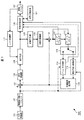
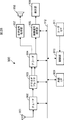
- FIG. 1 is a block diagram illustrating a main configuration example of an image encoding device.
- the image encoding device 100 shown in FIG. Like the H.264 and MPEG (Moving Picture Experts Group) 4 Part 10 (AVC (Advanced Video Coding)) coding system, the image data is encoded using a prediction process.
- H.264 and MPEG Motion Picture Experts Group 4 Part 10 (AVC (Advanced Video Coding)
- AVC Advanced Video Coding
- the image encoding device 100 includes an A / D conversion unit 101, a screen rearrangement buffer 102, a calculation unit 103, an orthogonal transformation unit 104, a quantization unit 105, a lossless encoding unit 106, and a storage buffer. 107.
- the image coding apparatus 100 also includes an inverse quantization unit 108, an inverse orthogonal transform unit 109, a calculation unit 110, a loop filter 111, a frame memory 112, a selection unit 113, an intra prediction unit 114, a motion prediction / compensation unit 115, and a prediction.
- An image selection unit 116 and a rate control unit 117 are included.
- the image encoding device 100 further includes an encoding control unit 121.
- the A / D conversion unit 101 performs A / D conversion on the input image data, and supplies the converted image data (digital data) to the screen rearrangement buffer 102 for storage.
- the screen rearrangement buffer 102 rearranges the images of the frames in the stored display order in the order of frames for encoding in accordance with GOP (Group Of Picture), and the images in which the order of the frames is rearranged. This is supplied to the calculation unit 103.
- the screen rearrangement buffer 102 also supplies the image in which the order of the frames is rearranged to the intra prediction unit 114 and the motion prediction / compensation unit 115.
- the calculation unit 103 subtracts the prediction image supplied from the intra prediction unit 114 or the motion prediction / compensation unit 115 via the prediction image selection unit 116 from the image read from the screen rearrangement buffer 102, and the difference information Is output to the orthogonal transform unit 104.
- the calculation unit 103 subtracts the predicted image supplied from the motion prediction / compensation unit 115 from the image read from the screen rearrangement buffer 102.
- the orthogonal transform unit 104 performs orthogonal transform such as discrete cosine transform and Karhunen-Loeve transform on the difference information supplied from the computation unit 103. Note that this orthogonal transformation method is arbitrary.
- the orthogonal transform unit 104 supplies the transform coefficient to the quantization unit 105.
- the quantization unit 105 quantizes the transform coefficient supplied from the orthogonal transform unit 104.
- the quantization unit 105 sets a quantization parameter based on the information regarding the target value of the code amount supplied from the rate control unit 117, and performs the quantization. Note that this quantization method is arbitrary.
- the quantization unit 105 supplies the quantized transform coefficient to the lossless encoding unit 106.
- the lossless encoding unit 106 encodes the transform coefficient quantized by the quantization unit 105 using an arbitrary encoding method. Since the coefficient data is quantized under the control of the rate control unit 117, the code amount becomes a target value set by the rate control unit 117 (or approximates the target value).
- the lossless encoding unit 106 acquires information indicating the mode of intra prediction from the intra prediction unit 114, and acquires information indicating the mode of inter prediction, motion vector information, and the like from the motion prediction / compensation unit 115. Further, the lossless encoding unit 106 acquires filter coefficients used in the loop filter 111 and the like.
- the lossless encoding unit 106 encodes these various types of information using an arbitrary encoding method, and makes it a part of the header information of the encoded data (multiplexes).
- the lossless encoding unit 106 supplies the encoded data obtained by encoding to the accumulation buffer 107 for accumulation.
- Examples of the encoding method of the lossless encoding unit 106 include variable length encoding or arithmetic encoding.
- Examples of variable length coding include H.264.
- CAVLC Context-Adaptive Variable Length Coding
- Examples of arithmetic coding include CABAC (Context-Adaptive Binary Arithmetic Coding).
- the accumulation buffer 107 temporarily holds the encoded data supplied from the lossless encoding unit 106.
- the accumulation buffer 107 outputs the stored encoded data to, for example, a recording device (recording medium) (not shown) or a transmission path (not shown) at a predetermined timing at a predetermined timing.
- the transform coefficient quantized by the quantization unit 105 is also supplied to the inverse quantization unit 108.
- the inverse quantization unit 108 inversely quantizes the quantized transform coefficient by a method corresponding to the quantization by the quantization unit 105.
- the inverse quantization method may be any method as long as it is a method corresponding to the quantization processing by the quantization unit 105.
- the inverse quantization unit 108 supplies the obtained transform coefficient to the inverse orthogonal transform unit 109.
- the inverse orthogonal transform unit 109 performs inverse orthogonal transform on the transform coefficient supplied from the inverse quantization unit 108 by a method corresponding to the orthogonal transform process by the orthogonal transform unit 104.
- the inverse orthogonal transform method may be any method as long as it corresponds to the orthogonal transform processing by the orthogonal transform unit 104.
- the inversely orthogonal transformed output (restored difference information) is supplied to the calculation unit 110.
- the calculation unit 110 is supplied from the intra prediction unit 114 or the motion prediction / compensation unit 115 via the prediction image selection unit 116 to the inverse orthogonal transform result supplied from the inverse orthogonal transform unit 109, that is, the restored difference information. Predicted images are added to obtain a locally decoded image (decoded image). The decoded image is supplied to the loop filter 111 or the frame memory 112.
- the loop filter 111 includes a deblock filter, an adaptive loop filter, and the like, and appropriately performs a filtering process on the decoded image supplied from the calculation unit 110.
- the loop filter 111 removes block distortion of the decoded image by performing a deblocking filter process on the decoded image.
- the loop filter 111 performs image quality improvement by performing loop filter processing using a Wiener filter on the deblock filter processing result (decoded image from which block distortion has been removed). Do.
- the loop filter 111 may perform arbitrary filter processing on the decoded image. Further, the loop filter 111 can supply information such as filter coefficients used for the filter processing to the lossless encoding unit 106 and encode it as necessary.
- the loop filter 111 supplies the filter process result (decoded image after the filter process) to the frame memory 112. As described above, the decoded image output from the calculation unit 110 can be supplied to the frame memory 112 without passing through the loop filter 111. That is, the filter process by the loop filter 111 can be omitted.
- the frame memory 112 stores the supplied decoded image, and supplies the stored decoded image as a reference image to the selection unit 113 at a predetermined timing.
- the selection unit 113 selects a supply destination of the reference image supplied from the frame memory 112. For example, in the case of inter prediction, the selection unit 113 supplies the reference image supplied from the frame memory 112 to the motion prediction / compensation unit 115.
- the intra prediction unit 114 basically uses the pixel value in the processing target picture, which is a reference image supplied from the frame memory 112 via the selection unit 113, to generate a prediction image using a prediction unit (PU) as a processing unit. Perform intra prediction (intra-screen prediction) to be generated. The intra prediction unit 114 performs this intra prediction in a plurality of modes (intra prediction modes) prepared in advance.
- the intra prediction unit 114 generates a prediction image in all candidate intra prediction modes, evaluates the cost function value of each prediction image using the input image supplied from the screen rearrangement buffer 102, and selects the optimum mode. select. When the intra prediction unit 114 selects the optimal intra prediction mode, the intra prediction unit 114 supplies the predicted image generated in the optimal mode to the predicted image selection unit 116.
- the intra prediction unit 114 appropriately supplies the intra prediction mode information indicating the adopted intra prediction mode to the lossless encoding unit 106 and causes the encoding to be performed.
- the motion prediction / compensation unit 115 basically uses the input image supplied from the screen rearrangement buffer 102 and the reference image supplied from the frame memory 112 via the selection unit 113 as a processing unit. Motion prediction (inter prediction) is performed, motion compensation processing is performed according to the detected motion vector, and a predicted image (inter predicted image information) is generated. The motion prediction / compensation unit 115 performs such inter prediction in a plurality of modes (inter prediction modes) prepared in advance.
- the motion prediction / compensation unit 115 generates a prediction image in all candidate inter prediction modes, evaluates the cost function value of each prediction image, and selects an optimal mode. When the optimal inter prediction mode is selected, the motion prediction / compensation unit 115 supplies the predicted image generated in the optimal mode to the predicted image selection unit 116.
- the motion prediction / compensation unit 115 transmits information indicating the inter prediction mode employed, information necessary for performing processing in the inter prediction mode when decoding the encoded data, and the like. To be encoded.
- the predicted image selection unit 116 selects a supply source of a predicted image to be supplied to the calculation unit 103 or the calculation unit 110. For example, in the case of inter coding, the prediction image selection unit 116 selects the motion prediction / compensation unit 115 as a supply source of the prediction image, and calculates the prediction image supplied from the motion prediction / compensation unit 115 as the calculation unit 103 or the calculation unit. To the unit 110.
- the rate control unit 117 controls the quantization operation rate of the quantization unit 105 based on the code amount of the encoded data stored in the storage buffer 107 so that overflow or underflow does not occur.
- the encoding control unit 121 controls the encoding process of the lossless encoding unit 106. At that time, the encoding control unit 121 determines whether to perform encoding in the merge mode. In the determination, the encoding control unit 121 sets a parameter called NumMergeCandidates used for the determination. NumMergeCandidates is a parameter related to a motion vector included in a peripheral area that is located around the area to be processed and that may refer to a motion vector in the merge mode. When the parameter is set, the encoding control unit 121 determines whether or not the peripheral region is included in the same slice (the relevant slice) as the relevant region with respect to the multi-sliced processing target picture (the relevant picture). Confirm.
- the encoding control unit 121 can use a peripheral area that can be referred to in the merge mode, or can not use it. Whether or not to enter the merge mode is determined in consideration of the existence of the merge mode, and the merge mode is controlled based on the determination result.
- the encoding control unit 121 also controls encoding processing for modes other than the merge mode, such as a skip mode, an intra prediction mode, an inter prediction mode, and a direct mode.
- the lossless encoding unit 106 performs the lossless encoding process in the mode selected by the encoding control unit 121.
- Multi-slice In an image encoding method such as MPEG2 or AVC, one picture can be divided into a plurality of slices, and each slice can be processed in parallel (multi-slice).
- the maximum size of a slice is one macroblock line, and all the slices constituting a B picture must be B slices.
- the slice may be larger than one macroblock line, and the boundary of the slice may not be the right end (right end of the screen) of the macroblock line.
- a single picture may be composed of different types of slices.
- the deblocking filter process can be executed across slice boundaries.
- processing using adjacent information such as intra prediction, CABAC, CAVLC, and motion vector prediction cannot be executed across slice boundaries.
- each slice since the encoding processing of each slice can be executed independently of each other, it is possible to divide one picture into a plurality of slices and encode each slice in parallel. That is, such slice division can realize reduction in encoding processing time (enhancement of encoding processing).
- a macroblock or a sub macroblock obtained by dividing the macroblock into a plurality of units is used as a processing unit such as a prediction process or an encoding process.
- the macroblock size of 16 pixels x 16 pixels is optimal for large image frames such as UHD (Ultra High Definition; 4000 pixels x 2000 pixels), which are subject to the next-generation encoding method. is not.
- AVC International Telecommunication Union Telecommunication Standardization Sector
- ISO International Organization for Standardization
- IEC International Electrotechnical Commission
- Standardization of an encoding method called HEVC High Efficiency Video Coding
- JCTVC Joint Collaboration Team Video Coding
- a hierarchical structure is defined by macroblocks and sub-macroblocks.
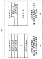
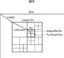
- a coding unit (CU (Coding Unit)) is defined as shown in FIG.
- CU is also called Coding Tree Block (CTB), and is a partial area of a picture unit image that plays the same role as a macroblock in AVC.
- CTB Coding Tree Block
- the latter is fixed to a size of 16 ⁇ 16 pixels, whereas the size of the former is not fixed, and is specified in the image compression information in each sequence.
- the maximum size (LCU (Largest Coding Unit)) and the minimum size ((SCU (Smallest Coding Unit)) are specified. Is done.
- the LCU size is 128 and the maximum hierarchical depth is 5.
- split_flag is “1”
- the 2N ⁇ 2N size CU is divided into N ⁇ N size CUs that are one level below.
- the CU is divided into prediction units (Prediction Units (PU)) that are regions (partial regions of images in units of pictures) that are processing units of intra or inter prediction, and are regions that are processing units of orthogonal transformation It is divided into transform units (Transform Unit (TU)), which is (a partial area of an image in units of pictures).
- Prediction Units PU
- transform Unit Transform Unit
- a macroblock in AVC corresponds to an LCU.
- the size of the LCU in the highest hierarchy is generally set larger than the AVC macroblock, for example, 128 ⁇ 128 pixels. is there.
- the present disclosure can be applied to an encoding method using such a CU, PU, TU, and the like instead of a macroblock. That is, the processing unit for performing the prediction process may be an arbitrary area. That is, in the following description, only such macroblocks and sub-macroblocks are included in a region to be processed in prediction processing (also referred to as the region or a region of interest) or a peripheral region located around the region. CU, PU, TU, etc. are included.
- LCUs (CU, PU, and TU) as described above are obtained by dividing a slice area into a plurality of parts and belong to the lower layer of the slice. That is, in the case of the multi-slice as described in FIG. 2, as shown in FIG. 4, the LCU is included in any slice.
- the LCU head address is specified by a relative position from the head of each slice.
- Identification information and size are designated for each area (CU, PU, and TU) in the LCU. That is, the position of each area (for example, the start address) can be specified from the information. Therefore, the position of the area and the peripheral area, and the range of the slice can be easily specified from the information. In other words, whether or not the peripheral region belongs to the slice (whether it is available or unavailable) can be easily specified.
- the slice boundary can be set in units of PUs. That is, there may be an LCU positioned so as to straddle a plurality of slices. Also in this case, a region corresponding to each motion vector such as PU (region of prediction processing unit) is included in any one slice.
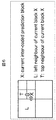
- Merge motion partition By the way, as one of the motion information encoding methods, a method called “Motion Partition Merging” (merge mode) as shown in FIG. 6 has been proposed. In this method, two flags, Merge_Flag and Merge_Left_Flag, are transmitted as merge information that is information related to the merge mode.
- Multi-slice merge mode As described above, in the merge mode, the motion information of the peripheral area is referred to. However, in the case of the multi-slice as described above, there is a possibility that the peripheral region L and the peripheral region T that may be referred to in the merge mode are located in a different slice from the region X.
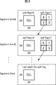
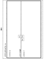
- FIG. 7 shows that the region (CU_X), the peripheral region (PU_T) adjacent to the region (CU_X), and the peripheral region (PU_L) adjacent to the left of the region (CU_X) are all one. A state of being located in (belonging to) the slice (slice 1) is shown.
- both the peripheral area (PU_T) and the peripheral area (PU_L) can be referred to (available).
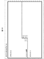
- FIG. 8 shows that the region (CU_X) and the peripheral region (PU_L) are located in slice 1 (belong to the slice), but the peripheral region (PU_T) is located in slice 0 (does not belong to the slice) It shows a state.
- peripheral area (PU_L) can be referred to (available), but the peripheral area (PU_T) cannot be referred to (unavailable).
- FIG. 9 shows that the region (CU_X) is located in slice 1 (belongs to the slice), but the peripheral region (PU_T) and the peripheral region (PU_L) are located in slice 0 (does not belong to the slice) It shows a state.
- peripheral area (PU_T) and the peripheral area (PU_L) cannot be referenced (unavailable).
- FIG. 10 shows that the region (CU_X) and the peripheral region (PU_T) are located in the slice 1 (belonging to the slice), but the peripheral region (PU_L) is located in the slice 0 (does not belong to the slice) It shows a state.
- peripheral area (PU_T) can be referred to (available), but the peripheral area (PU_L) cannot be referred to (unavailable).
- the slice boundary includes a picture edge in addition to the boundary between slices. What is important is whether or not the peripheral area is available, that is, whether or not the peripheral area is included in the slice. Therefore, the state where the peripheral area is unavailable includes not only the case where the peripheral area belongs to another slice but also the case where the peripheral area does not exist (will be located outside the picture). It is.
- FIG. 11 shows an example of CU syntax.
- FIG. 12 shows an example of PU syntax.
- the number at the left end of each row is the row number given for convenience of explanation.
- the value of the parameter NumMergeCandidates is used to determine whether or not to adopt the merge mode.
- This parameter indicates the count value (total number) of motion vectors included in a peripheral area (a candidate area to be merged with the area) that may be merged with the area in the merge mode.
- the encoding control unit 121 in FIG. 1 assumes that this NumMergeCandidates is greater than 0 as one of the conditions for adopting the merge mode.
- a value of 0 for NumMergeCandidates indicates that there is no region having motion information among the candidate regions to be merged with the region. In this case, since merging is impossible, the encoding control unit 121 controls to adopt a mode other than the merge mode.
- this NumMergeCandidates In order to accurately obtain this NumMergeCandidates, it is necessary to confirm the motion information of all surrounding areas that are candidates for the area to be merged with the area concerned. In other words, this NumMergeCandidates is necessary in determining whether or not to adopt the merge mode, and in order to obtain the value, it is necessary to refer to the motion information of the surrounding area. Therefore, as described above, when there is an unusable peripheral region, parallel processing becomes difficult even when determining whether to adopt the merge mode, which may cause a delay.
- the encoding control unit 121 determines whether or not there is a motion vector only for the peripheral region existing in the slice, and obtains NumMergeCandidates. That is, the encoding control unit 121 counts the peripheral area (increments NumMergeCandidates) only when the peripheral area exists in the slice and has a motion vector.
- a peripheral region that does not belong to the slice is excluded from candidate regions to be merged with the region.
- only a peripheral region belonging to the slice is a candidate for a region to be merged with the region. Therefore, even when the merge mode is adopted, only the peripheral area belonging to the slice is merged into the area, so that it is not necessary to refer to the motion vector of the peripheral area that does not belong to the slice.
- the image coding apparatus 100 can realize parallel processing for each slice, and can suppress an increase in processing time due to generation of an unnecessary delay time in processing related to the merge mode.
- the encoding control unit 121 may calculate NumMergeCandidates as described above, and there is no need to change the syntax. Therefore, development is easy, and there is no fear of increasing the code amount or reducing versatility.
- the slice described above may be a processing unit that can be processed in parallel by dividing a picture into a plurality of pieces. Therefore, this slice includes, for example, an entropy slice in addition to a normal slice.
- this slice includes, for example, an entropy slice in addition to a normal slice.
- the shape, number and position of slices are arbitrary. That is, the picture division position and the number of divisions are arbitrary.
- the slice 1 is described as the slice, but the same applies to any slice that is the slice.
- the same applies to the case where the area in slice 0 or slice 2 is the area concerned.
- the encoding control unit 121 performs the motion vector of the peripheral area in the same manner as when the peripheral area exists in another slice. Do not increment NumMergeCandidates.
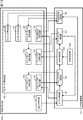
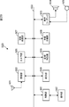
- FIG. 13 is a block diagram illustrating a main configuration example of the lossless encoding unit 106 and the encoding control unit 121.
- the lossless encoding unit 106 includes a NAL (Network Abstraction Layer) encoding unit 131 and a CU data encoding unit 132.
- NAL Network Abstraction Layer
- the NAL encoding unit 131 encodes NAL data such as a sequence parameter set (SPS (Sequence Parameter Set)), a picture parameter set (PPS (Picture Parameter Set)), and a slice header.
- SPS Sequence Parameter Set
- PPS Picture Parameter Set
- the CU data encoding unit 132 encodes data in a layer below the CU (VCL (Video Coding Layer)).
- the CU data encoding unit 132 includes a skip flag encoding unit 141, a skip mode encoding unit 142, a merge flag encoding unit 143, and a merge mode encoding unit 144.
- the CU data encoding unit 132 includes a PredMode encoding unit 145, an intra encoding unit 146, an inter encoding unit 147, and a direct mode encoding unit 148.
- the skip flag encoding unit 141 generates and encodes a skip flag indicating whether or not to adopt the skip mode, under the control of the encoding control unit 121.
- the skip mode encoding unit 142 performs encoding processing in the skip mode according to the control of the encoding control unit 121.
- the merge flag encoding unit 143 generates and encodes a merge flag (MergeFlag) indicating whether or not to adopt the merge mode in accordance with the control of the encoding control unit 121.
- the merge mode encoding unit 144 performs encoding processing in the merge mode according to the control of the encoding control unit 121.
- the PredMode encoding unit 145 encodes PredMode, which is a parameter indicating the prediction mode, under the control of the encoding control unit 121.
- the intra encoding unit 146 performs processing related to encoding of the difference image generated using the intra prediction according to the control of the encoding control unit 121.
- the inter coding unit 147 performs processing related to coding of a difference image generated using inter prediction according to the control of the coding control unit 121.
- the direct mode encoding unit 148 performs processing related to encoding of the difference image generated using the direct mode according to the control of the encoding control unit 121.
- the encoding control unit 121 includes a slice determination unit 161, a skip flag determination unit 162, an NMC (NumMergeCandidates) setting unit 163, an NMC determination unit 164, a merge flag determination unit 165, and a PredMode determination. Part 166.
- the slice determination unit 161 determines the type of the slice, and supplies the determination result to the skip flag encoding unit 141 and the PredMode encoding unit 145 or the skip flag determination unit 162.
- the skip flag determination unit 162 determines the value (or presence) of the skip flag generated (or not generated) in the skip flag encoding unit 141, and the determination result is used as the skip mode encoding unit 142 or NMC. It supplies to the determination part 164.
- the NMC setting unit 163 obtains (sets) the value of the parameter NumMergeCandidates and supplies the value to the NMC determination unit 164.
- the NMC determination unit 164 determines the value of NumMergeCandidates and supplies the determination result to the merge flag encoding unit 143 or the merge flag determination unit 165.
- the merge flag determination unit 165 determines the value (or presence) of the merge flag generated (or not generated) in the merge flag encoding unit 143, and the determination result is the merge mode encoding unit 144 or slice determination unit. 161.
- the PredMode determining unit 166 determines the value (or presence) of the PredMode generated (or not) in the PredMode encoding unit 145, and determines the determination result as the intra encoding unit 146, the inter encoding unit 147, or This is supplied to the direct mode encoding unit 148.
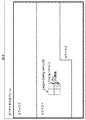
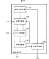
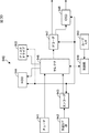
- FIG. 14 is a block diagram illustrating a main configuration example of the NMC setting unit 163.
- the NMC setting unit 163 includes an NMC reset unit 181, a position determination unit 182, a type determination unit 183, an NMC update unit 184, and an NMC holding unit 185.
- the NMC reset unit 181 resets the value of the parameter NumMergeCandidates held in the NMC holding unit 185 to 0.
- the position determination unit 182 When the position determination unit 182 receives a reset notification from the NMC reset unit 181, receives a notification of updating the value of NumMergeCandidates from the NMC update unit 184, or acquires a determination result from the type determination unit 183, the position determination unit 182 Information on the position of the slice and the area X is acquired from the unit 131, the position of the area X is obtained, the positions of the peripheral area T and the peripheral area L are obtained from the position of the area X, and they exist in the slice It is determined whether or not. The position determination unit 182 supplies the determination result to the type determination unit 183.
- the type determination unit 183 determines the prediction type of the peripheral region L and the peripheral region T existing in the slice from the CU data encoding unit 132. That is, the type determination unit 183 determines whether or not the surrounding area L and the surrounding area T have motion information.
- the type determination unit 183 supplies the determination result to the position determination unit 182 or the NMC update unit 184.
- the NMC update unit 184 increments (+1) the value of the parameter NumMergeCandidates held in the NMC holding unit 185. That is, the NMC update unit 184 increments (+1) the value of the parameter NumMergeCandidates held in the NMC holding unit 185 when the peripheral area located in the slice has motion information.
- the NMC holding unit 185 supplies the value of the held parameter NumMergeCandidates to the NMC determination unit 164 at a predetermined timing or in response to a request from the NMC determination unit 164.
- step S101 the A / D converter 101 performs A / D conversion on the input image.
- step S102 the screen rearrangement buffer 102 stores the A / D converted image, and rearranges the picture from the display order to the encoding order.
- step S103 the intra prediction unit 114 performs an intra prediction process in the intra prediction mode.
- step S104 the motion prediction / compensation unit 115 performs an inter motion prediction process for performing motion prediction and motion compensation in the inter prediction mode.
- step S105 the predicted image selecting unit 116 determines an optimal mode based on the cost function values output from the intra prediction unit 114 and the motion prediction / compensation unit 115. That is, the predicted image selection unit 116 selects one of the predicted image generated by the intra prediction unit 114 and the predicted image generated by the motion prediction / compensation unit 115.
- step S106 the calculation unit 103 calculates a difference between the image rearranged by the process of step S102 and the predicted image selected by the process of step S105.
- the data amount of the difference data is reduced compared to the original image data. Therefore, the data amount can be compressed as compared with the case where the image is encoded as it is.
- step S107 the orthogonal transform unit 104 orthogonally transforms the difference information generated by the process in step S106. Specifically, orthogonal transformation such as discrete cosine transformation and Karhunen-Loeve transformation is performed, and transformation coefficients are output.
- orthogonal transformation such as discrete cosine transformation and Karhunen-Loeve transformation is performed, and transformation coefficients are output.
- step S108 the quantization unit 105 quantizes the orthogonal transform coefficient obtained by the process in step S107.
- step S109 the inverse quantization unit 108 inversely quantizes the quantized orthogonal transform coefficient (also referred to as a quantization coefficient) generated by the process in step S108 with characteristics corresponding to the characteristics of the quantization unit 105.
- step S ⁇ b> 110 the inverse orthogonal transform unit 109 performs inverse orthogonal transform on the orthogonal transform coefficient obtained by the process of step S ⁇ b> 107 with characteristics corresponding to the characteristics of the orthogonal transform unit 104.
- step S111 the calculation unit 110 adds the predicted image to the locally decoded difference information, and generates a locally decoded image (an image corresponding to an input to the calculation unit 103).
- step S112 the loop filter 111 appropriately performs a loop filter process including a deblock filter process and an adaptive loop filter process on the locally decoded image obtained by the process of step S111.
- step S113 the frame memory 112 stores the decoded image that has been subjected to the loop filter process by the process of step S112. It should be noted that an image that has not been filtered by the loop filter 111 is also supplied from the calculation unit 110 and stored in the frame memory 112.
- step S114 the lossless encoding unit 106 encodes the transform coefficient quantized by the process in step S108. That is, lossless encoding such as variable length encoding or arithmetic encoding is performed on the difference image.
- the lossless encoding unit 106 encodes the quantization parameter calculated in step S108 and adds it to the encoded data. Further, the lossless encoding unit 106 encodes information related to the prediction mode of the prediction image selected by the process of step S105, and adds the encoded information to the encoded data obtained by encoding the difference image. That is, the lossless encoding unit 106 also encodes and encodes the optimal intra prediction mode information supplied from the intra prediction unit 114 or information according to the optimal inter prediction mode supplied from the motion prediction / compensation unit 115, and the like. Append to data.
- step S115 the accumulation buffer 107 accumulates the encoded data obtained by the process in step S114.
- the encoded data stored in the storage buffer 107 is appropriately read and transmitted to the decoding side via a transmission path or a recording medium.
- step S116 the rate control unit 117 causes the quantization unit 105 to prevent overflow or underflow based on the code amount (generated code amount) of the encoded data accumulated in the accumulation buffer 107 by the process of step S115. Controls the rate of quantization operation.
- step S116 When the process of step S116 is finished, the encoding process is finished.
- step S ⁇ b> 114 the lossless encoding unit 106 performs an encoding process according to the control of the encoding control unit 121.
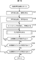
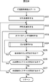
- the NAL encoding unit 131 generates and encodes an SPS in step S121, generates and encodes a PPS in step S122, and generates and encodes a slice header in step S123.
- the CU data encoding unit 132 encodes the CU to be processed.
- the CU data encoding unit 132 repeats the process of step S124 for all CUs in the slice to be processed. If it is determined in step S125 that there is no unprocessed CU in the slice, the CU data encoding unit 132 proceeds with the process to step S126.
- the NAL encoding unit 131 repeats the processing from step S123 to step S125 for all slices in the picture to be processed. If it is determined in step S126 that there is no unprocessed slice in the picture, the NAL encoding unit 131 advances the process to step S127.
- the NAL encoding unit 131 repeats the processing from step S122 to step S126 for all the pictures in the sequence to be processed. If it is determined in step S127 that there is no unprocessed picture in the sequence, the NAL encoding unit 131 ends the lossless encoding process and returns the process to FIG.
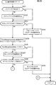
- the slice determination unit 161 determines the type of the slice from the NAL data generated by the NAL encoding unit 131 in step S131, and whether or not the slice is an I slice. Determine whether. Only when the slice is not an I slice (P slice or B slice), the skip flag encoding unit 141 generates and encodes a skip flag in step S132.
- the skip flag determination unit 162 determines that the value of the skip flag is 1 in step S133
- the skip mode encoding unit 142 that has acquired the determination result from the skip flag determination unit 162 determines that the skip mode in step S134. To encode the CU data.
- the CU encoding process ends, and the process returns to FIG.
- step S133 in FIG. 17 when the skip flag determination unit 162 determines in step S133 in FIG. 17 that the value of the skip flag is 0 or the skip flag does not exist, the skip flag determination unit 162 advances the processing to step S135. . In this case, encoding in the skip mode is not performed.
- step S135 the NMC setting unit 163 sets NumMergeCandidates.
- the merge flag encoding unit 143 Only when the NMC determining unit 164 determines in step S136 that the value of NumMergeCandidates set in step S135 is greater than 0, the merge flag encoding unit 143 generates and encodes a merge flag in step S137. .
- the merge mode encoding unit 144 that has acquired the determination result from the merge flag determination unit 165 performs the CU in merge mode in step S139. Encode the data.
- the CU encoding process ends, and the process returns to FIG.
- step S138 of FIG. 17 if the merge flag determination unit 165 determines that the value of the merge flag is 0 or that the merge flag does not exist, the process proceeds to the flowchart of FIG. Encoding according to the mode is performed.
- the PredMode encoding unit 145 indicates a parameter indicating the type of prediction mode of the slice in step S142. Is generated and encoded.
- step S143 when the PredMode determination unit 166 refers to PredMode and determines that the prediction mode of the region is the intra prediction mode, the intra encoding unit 146 encodes the CU data in the intra prediction mode in step S144. Turn into. That is, difference image information (quantized orthogonal transform coefficient), information on the intra prediction mode, and the like are encoded.
- difference image information quantized orthogonal transform coefficient
- the CU encoding process ends, and the process returns to FIG.
- the inter coding unit 147 performs the inter prediction in step S146.
- Encode mode CU data That is, difference image information (quantized orthogonal transform coefficient), information on the inter prediction mode, and the like are encoded.
- the direct mode encoding unit 148 performs direct processing in step S147.
- CU data in prediction mode is encoded.
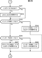
- step S151 the NMC reset unit 181 resets the parameter NumMergeCandidates held in the NMC holding unit 185 to the initial value “0”.
- step S152 Only when the position determination unit 182 determines in step S152 that the peripheral region PU_L exists in the slice, and in step S153, the type determination unit 183 determines that the prediction mode of the peripheral region PU_L is not intra prediction.
- step S154 the NMC update unit 184 increments (+1) the value of the parameter NumMergeCandidates held in the NMC holding unit 185.
- step S152 the position determination unit 182 determines that the peripheral region PU_L does not exist in the slice, or in step S153, the type determination unit 183 determines that the prediction mode of the peripheral region PU_L is intra prediction. Or the value of the parameter NumMergeCandidates is not incremented (+1).
- step S158 the NMC holding unit 185 supplies the value of the held NumMergeCandidates to the NMC determination unit 164.
- the NumMergeCandidates setting process is terminated, and the process returns to FIG.
- the image encoding apparatus 100 can realize parallel processing for each slice, and suppress an increase in processing time due to generation of unnecessary delay time in processing related to the merge mode. can do.
- FIG. 20 is a block diagram illustrating a main configuration example of an image decoding device.
- the image decoding apparatus 200 shown in FIG. 20 decodes the encoded data generated by the image encoding apparatus 100 by a decoding method corresponding to the encoding method. Note that, similarly to the image encoding device 100, the image decoding device 200 performs a prediction process for each arbitrary region (for example, a prediction unit (PU)).
- PU prediction unit
- the image decoding apparatus 200 includes a storage buffer 201, a lossless decoding unit 202, an inverse quantization unit 203, an inverse orthogonal transform unit 204, a calculation unit 205, a loop filter 206, a screen rearrangement buffer 207, and a D A / A converter 208 is included.
- the image decoding apparatus 200 includes a frame memory 209, a selection unit 210, an intra prediction unit 211, a motion prediction / compensation unit 212, and a selection unit 213.
- the image decoding device 200 includes a decoding control unit 221.
- the accumulation buffer 201 accumulates the transmitted encoded data, and supplies the encoded data to the lossless decoding unit 202 at a predetermined timing.
- the lossless decoding unit 202 decodes the information supplied from the accumulation buffer 201 and encoded by the lossless encoding unit 106 in FIG. 1 by a method corresponding to the encoding method of the lossless encoding unit 106.
- the lossless decoding unit 202 supplies the quantized coefficient data of the difference image obtained by decoding to the inverse quantization unit 203.
- the lossless decoding unit 202 determines whether the intra prediction mode is selected as the optimal prediction mode or the inter prediction mode, and uses the intra prediction unit 211 and the motion prediction / compensation unit as information on the optimal prediction mode.
- the data is supplied to the mode determined to be selected from among 212. That is, for example, when the inter prediction mode is selected as the optimal prediction mode in the image encoding device 100, information regarding the optimal prediction mode is supplied to the motion prediction / compensation unit 212.
- the inverse quantization unit 203 inversely quantizes the quantized coefficient data obtained by decoding by the lossless decoding unit 202 using a method corresponding to the quantization method of the quantization unit 105 in FIG. Data is supplied to the inverse orthogonal transform unit 204.
- the inverse orthogonal transform unit 204 performs inverse orthogonal transform on the coefficient data supplied from the inverse quantization unit 203 in a method corresponding to the orthogonal transform method of the orthogonal transform unit 104 in FIG.
- the inverse orthogonal transform unit 204 obtains decoded residual data corresponding to the residual data before being orthogonally transformed in the image coding apparatus 100 by the inverse orthogonal transform process.
- the decoded residual data obtained by the inverse orthogonal transform is supplied to the calculation unit 205.
- a prediction image is supplied to the calculation unit 205 from the intra prediction unit 211 or the motion prediction / compensation unit 212 via the selection unit 213.
- the calculation unit 205 adds the decoded residual data and the prediction image, and obtains decoded image data corresponding to the image data before the prediction image is subtracted by the calculation unit 103 of the image encoding device 100.
- the arithmetic unit 205 supplies the decoded image data to the loop filter 206.
- the loop filter 206 appropriately performs a loop filter process including a deblock filter process and an adaptive loop filter process on the supplied decoded image, and supplies it to the screen rearrangement buffer 207.
- the loop filter 206 includes a deblocking filter, an adaptive loop filter, and the like, and appropriately performs a filtering process on the decoded image supplied from the calculation unit 205.
- the loop filter 206 removes block distortion of the decoded image by performing a deblocking filter process on the decoded image.
- the loop filter 206 improves the image quality by performing loop filter processing using a Wiener filter on the deblock filter processing result (the decoded image from which block distortion has been removed). Do.
- loop filter 206 may perform arbitrary filter processing on the decoded image. Further, the loop filter 206 may perform filter processing using the filter coefficient supplied from the image encoding device 100 of FIG.
- the loop filter 206 supplies the filter processing result (the decoded image after the filter processing) to the screen rearrangement buffer 207 and the frame memory 209. Note that the decoded image output from the calculation unit 205 can be supplied to the screen rearrangement buffer 207 and the frame memory 209 without going through the loop filter 206. That is, the filter process by the loop filter 206 can be omitted.
- the screen rearrangement buffer 207 rearranges images. That is, the order of frames rearranged for the encoding order by the screen rearrangement buffer 102 in FIG. 1 is rearranged in the original display order.
- the D / A conversion unit 208 D / A converts the image supplied from the screen rearrangement buffer 207, outputs it to a display (not shown), and displays it.
- the frame memory 209 stores the supplied decoded image, and the stored decoded image is referred to as a reference image at a predetermined timing or based on an external request such as the intra prediction unit 211 or the motion prediction / compensation unit 212. To the selection unit 210.
- the selection unit 210 selects the supply destination of the reference image supplied from the frame memory 209.
- the selection unit 210 supplies the reference image supplied from the frame memory 209 to the intra prediction unit 211 when decoding an intra-coded image.
- the selection unit 210 also supplies the reference image supplied from the frame memory 209 to the motion prediction / compensation unit 212 when decoding an inter-coded image.
- the intra prediction unit 211 is appropriately supplied from the lossless decoding unit 202 with information indicating the intra prediction mode obtained by decoding the header information.
- the intra prediction unit 211 performs intra prediction using the reference image acquired from the frame memory 209 in the intra prediction mode used in the intra prediction unit 114 in FIG. 1, and generates a predicted image.
- the intra prediction unit 211 supplies the generated predicted image to the selection unit 213.
- the motion prediction / compensation unit 212 acquires information obtained by decoding header information (optimum prediction mode information, difference information, code number of prediction motion vector information, etc.) from the lossless decoding unit 202.
- the motion prediction / compensation unit 212 performs inter prediction using the reference image acquired from the frame memory 209 in the inter prediction mode used in the motion prediction / compensation unit 115 of FIG. 1 to generate a prediction image.
- the decoding control unit 221 controls the decoding process of the lossless decoding unit 202.
- the lossless decoding unit 202 basically performs decoding processing by a method corresponding to the lossless encoding unit 106 in FIG. 1, and therefore, the control method of the decoding control unit 221 is basically the encoding control unit 121 in FIG. 1. This is the same as the control method.
- the decoding control unit 221 can select a decoding method corresponding to the encoding method selected by the encoding control unit 121 so that the decoding process is performed correctly. Can be controlled.
- the decoding control unit 221 determines whether to perform decoding in the merge mode. At the time of the determination, the decoding control unit 221 sets a parameter called NumMergeCandidates. When the parameter is set, the decoding control unit 221 confirms whether or not a peripheral region is included in the slice for the multi-sliced picture.
- the decoding control unit 221 determines whether the peripheral area that can be referred to in the merge mode is available (available) or unavailable (unavailable) in the decoding process control of the lossless decoding unit 202. It is determined whether or not the merge mode is set in consideration, and the merge mode is controlled based on the determination result.
- the decoding control unit 221 also controls the decoding process for modes other than the merge mode, such as a skip mode, an intra prediction mode, an inter prediction mode, and a direct mode.
- the lossless decoding unit 202 performs the lossless decoding process in the mode selected by the decoding control unit 221.
- the decoding control unit 221 and the lossless decoding unit 202 need only refer to the motion information in the slice, so there is no need to wait until the processing of another slice is completed. Therefore, the image decoding apparatus 200 can realize parallel processing for each slice, and can suppress an increase in processing time due to generation of an unnecessary delay time in processing related to the merge mode.
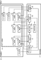
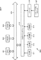
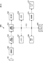
- FIG. 21 is a block diagram illustrating a main configuration example of the lossless decoding unit 202 and the decoding control unit 221.
- the lossless decoding unit 202 includes a NAL decoding unit 231 and a CU data decoding unit 232.
- the NAL decoding unit 231 decodes NAL encoded data such as a sequence parameter set, a picture parameter set, and a slice header.
- the CU data decoding unit 232 decodes the encoded data in the hierarchy below the CU.
- the CU data decoding unit 232 includes a skip flag decoding unit 241, a skip mode decoding unit 242, a merge flag decoding unit 243, and a merge mode decoding unit 244.
- the CU data decoding unit 232 includes a PredMode decoding unit 245, an intra decoding unit 246, an inter decoding unit 247, and a direct mode decoding unit 248.
- the skip flag decoding unit 241 decodes the skip flag according to the control of the decoding control unit 221.
- the skip mode decoding unit 242 performs a decoding process in the skip mode according to the control of the decoding control unit 221.
- the merge flag decoding unit 243 decodes the merge flag (MergeFlag) according to the control of the decoding control unit 221.
- the merge mode decoding unit 244 performs a decoding process in the merge mode according to the control of the decoding control unit 221.
- the PredMode decoding unit 245 decodes PredMode according to the control of the decoding control unit 221.
- the intra decoding unit 246 performs processing related to decoding of encoded data of the difference image generated using intra prediction according to the control of the decoding control unit 221.
- the inter decoding unit 247 performs processing related to decoding of encoded data of a difference image generated using inter prediction according to the control of the decoding control unit 221.
- the direct mode decoding unit 248 performs processing related to decoding of encoded data of the difference image generated using the direct mode according to the control of the decoding control unit 221.
- the decoding control unit 221 performs basically the same control as the encoding control unit 121. That is, as illustrated in FIG. 21, the decoding control unit 221 includes a slice determination unit 261, a skip flag determination unit 262, an NMC setting unit 263, an NMC determination unit 264, a merge flag determination unit 265, and a PredMode determination unit 266. .
- the slice determination unit 261 through PredMode determination unit 266 perform basically the same processing as the slice determination unit 261 through PredMode determination unit 166 of the encoding control unit 121, respectively.
- FIG. 22 is a block diagram illustrating a main configuration example of the NMC setting unit 263.
- the NMC setting unit 263 performs basically the same processing as the NMC setting unit 163. That is, the NMC setting unit 263 includes an NMC reset unit 281, a position determination unit 282, a type determination unit 283, an NMC update unit 284, and an NMC holding unit 285, as shown in FIG.
- the NMC reset unit 281 to NMC holding unit 285 perform basically the same processing as the NMC reset unit 181 to NMC 185, respectively.
- step S201 the accumulation buffer 201 accumulates the transmitted code stream.
- step S202 the lossless decoding unit 202 decodes the code stream supplied from the accumulation buffer 201. That is, the I picture, P picture, and B picture encoded by the lossless encoding unit 106 in FIG. 1 are decoded.
- Various information other than the difference image information included in the code stream such as difference motion information, code number of predicted motion vector information, and merge information, is also decoded.
- step S203 the inverse quantization unit 203 inversely quantizes the quantized orthogonal transform coefficient obtained by the process in step S202.
- step S204 the inverse orthogonal transform unit 204 performs inverse orthogonal transform on the orthogonal transform coefficient inversely quantized in step S203.
- step S205 the intra prediction unit 211 or the motion prediction / compensation unit 212 performs a prediction process using the supplied information.
- step S206 the selection unit 213 selects the predicted image generated in step S205.
- step S207 the calculation unit 205 adds the predicted image selected in step S206 to the difference image information obtained by the inverse orthogonal transform in step S204. Thereby, a decoded image is obtained.
- step S208 the loop filter 206 appropriately performs a loop filter process including a deblock filter process and an adaptive loop filter process on the decoded image obtained in step S207.
- step S209 the screen rearrangement buffer 207 rearranges the images filtered in step S208. That is, the order of frames rearranged for encoding by the screen rearrangement buffer 102 of the image encoding device 100 is rearranged to the original display order.
- step S210 the D / A converter 208 D / A converts the image in which the frame order is rearranged in step S209. This image is output to a display (not shown), and the image is displayed.
- step S211 the frame memory 209 stores the image filtered in step S208.
- this image is used as a reference image for generating a predicted image.
- step S211 When the process of step S211 is completed, the decryption process is terminated.
- This lossless decoding process is performed for each image layer, as in the case of the lossless encoding process.
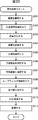
- the NAL decoding unit 231 decodes the SPS encoded data in step S221, decodes the PPS encoded data in step S222, and decodes the encoded data of the slice header in step S223.
- the CU data decoding unit 232 decodes the CU to be processed.
- the CU data decoding unit 232 repeats the process of step S224 for all the CUs in the slice that is the processing target. If it is determined in step S225 that there is no unprocessed CU in the slice, the CU data decoding unit 232 advances the process to step S226.
- the NAL decoding unit 231 repeats the processing from step S223 to step S225 for all slices in the picture to be processed. If it is determined in step S226 that there is no unprocessed slice in the picture, the NAL decoding unit 231 advances the process to step S227.
- the NAL decoding unit 231 repeats the processing from step S222 to step S226 for all the pictures in the sequence to be processed. If it is determined in step S227 that there is no unprocessed picture in the sequence, the NAL decoding unit 231 ends the lossless decoding process and returns the process to FIG.
- the slice determination unit 261 determines the type of the slice from the NAL data decoded by the NAL decoding unit 231 in step S231, and determines whether the slice is an I slice. judge.
- the skip flag decoding unit 241 decodes the skip flag in step S232. If it is determined that the slice is an I slice, the skip flag is not encoded, so this process is omitted.
- step S233 determines in step S233 that a skip flag exists and its value is 1, the skip mode decoding unit 242 decodes CU data in the skip mode in step S234.
- the skip mode decoding unit 242 ends the CU decoding process and returns the process to FIG.
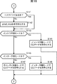
- step S233 when the skip flag determination unit 262 determines that the skip flag does not exist or the value is 0, the NMC setting unit 263 sets NumMergeCandidates in step S235. Since this NumMergeCandidates setting process is performed in the same manner as described with reference to the flowchart of FIG. 19, the detailed description of the NumMergeCandidates setting process is omitted.
- the merge flag decoding unit 243 decodes the merge flag in step S237. If it is determined that the value of NumMergeCandidates is 0, the merge flag is not encoded, so this process is omitted.
- step S2308 when the merge flag determination unit 265 determines that the merge flag exists and the value thereof is 1, the merge mode decoding unit 244 decodes the CU data in the merge mode in step S239.
- the merge mode decoding unit 244 ends the CU decoding process and returns the process to FIG.
- step S2308 if the merge flag determination unit 265 determines that the merge flag does not exist or the value thereof is 0, the process proceeds to FIG.
- CU data is decoded by a method according to the prediction mode. That is, if the slice determination unit 261 determines in step S241 in FIG. 26 that the slice is not an I slice, the PredMode decoding unit 245 decodes pred_mode in step S242. If it is determined that the slice is an I slice, pred_mode is not encoded, and thus this process is omitted.
- step S243 when the PredMode determination unit 266 determines that the prediction mode of the region is the intra prediction mode, the intra decoding unit 246 decodes in the intra prediction mode (encoded in the intra prediction mode) in step S244. CU data is decrypted in an appropriate manner). When the CU data is decoded, the intra decoding unit 246 ends the CU decoding process and returns the process to FIG.
- the inter decoding unit 247 determines that the inter decoding unit 247 in step S246 Decode in prediction mode (decode CU data encoded in inter prediction mode with an appropriate method).
- the inter decoding unit 247 ends the CU decoding process and returns the process to FIG.
- the direct mode decoding unit 248 determines in step S247 that Decode in direct prediction mode (decode CU data encoded in direct prediction mode with an appropriate method).
- the direct mode decoding unit 248 ends the CU decoding process and returns the process to FIG.
- the decoding control unit 221 and the lossless decoding unit 202 need only refer to the motion information in the slice, and thus need to wait until the processing of other slices is completed. Absent. Therefore, the image decoding apparatus 200 can realize parallel processing for each slice, and can suppress an increase in processing time due to generation of an unnecessary delay time in processing related to the merge mode.
- this technology is, for example, MPEG, H.264.
- image information bitstream
- orthogonal transformation such as discrete cosine transformation and motion compensation, such as 26x
- network media such as satellite broadcasting, cable television, the Internet, or mobile phones.
- the present invention can be applied to an image encoding device and an image decoding device used in
- the present technology can be applied to an image encoding device and an image decoding device that are used when processing on a storage medium such as an optical, magnetic disk, and flash memory.
- the present technology can also be applied to motion prediction / compensation devices included in such image encoding devices and image decoding devices.
- a CPU (Central Processing Unit) 501 of the personal computer 500 performs various processes according to a program stored in a ROM (Read Only Memory) 502 or a program loaded from a storage unit 513 to a RAM (Random Access Memory) 503. Execute the process.
- the RAM 503 also appropriately stores data necessary for the CPU 501 to execute various processes.
- the CPU 501, the ROM 502, and the RAM 503 are connected to each other via a bus 504.
- An input / output interface 510 is also connected to the bus 504.
- the input / output interface 510 includes an input unit 511 including a keyboard and a mouse, a display including a CRT (Cathode Ray Tube) and an LCD (Liquid Crystal Display), an output unit 512 including a speaker, and a hard disk.
- a communication unit 514 including a storage unit 513 and a modem is connected. The communication unit 514 performs communication processing via a network including the Internet.
- a drive 515 is connected to the input / output interface 510 as necessary, and a removable medium 521 such as a magnetic disk, an optical disk, a magneto-optical disk, or a semiconductor memory is appropriately mounted, and a computer program read from them is It is installed in the storage unit 513 as necessary.
- a removable medium 521 such as a magnetic disk, an optical disk, a magneto-optical disk, or a semiconductor memory is appropriately mounted, and a computer program read from them is It is installed in the storage unit 513 as necessary.
- a program constituting the software is installed from a network or a recording medium.
- the recording medium is distributed to distribute the program to the user separately from the apparatus main body, and includes a magnetic disk (including a flexible disk) on which the program is recorded, an optical disk ( It only consists of removable media 521 consisting of CD-ROM (compact disc -read only memory), DVD (including digital Versatile disc), magneto-optical disk (including MD (mini disc)), or semiconductor memory. Rather, it is composed of a ROM 502 on which a program is recorded and a hard disk included in the storage unit 513, which is distributed to the user in a state of being pre-installed in the apparatus main body.
- a magnetic disk including a flexible disk
- an optical disk It only consists of removable media 521 consisting of CD-ROM (compact disc -read only memory), DVD (including digital Versatile disc), magneto-optical disk (including MD (mini disc)), or semiconductor memory. Rather, it is composed of a ROM 502 on which a program is recorded and a hard disk included in the storage unit 513, which is
- the program executed by the computer may be a program that is processed in time series in the order described in this specification, or in parallel or at a necessary timing such as when a call is made. It may be a program for processing.
- the step of describing the program recorded on the recording medium is not limited to the processing performed in chronological order according to the described order, but may be performed in parallel or It also includes processes that are executed individually.
- system represents the entire apparatus composed of a plurality of devices (apparatuses).
- the configuration described as one device (or processing unit) may be divided and configured as a plurality of devices (or processing units).
- the configurations described above as a plurality of devices (or processing units) may be combined into a single device (or processing unit).
- a configuration other than that described above may be added to the configuration of each device (or each processing unit).
- a part of the configuration of a certain device (or processing unit) may be included in the configuration of another device (or other processing unit). . That is, the present technology is not limited to the above-described embodiment, and various modifications can be made without departing from the gist of the present technology.
- An image encoding device and an image decoding device include a transmitter or a receiver in optical broadcasting, satellite broadcasting, cable broadcasting such as cable TV, distribution on the Internet, and distribution to terminals by cellular communication
- the present invention can be applied to various electronic devices such as a recording device that records an image on a medium such as a magnetic disk and a flash memory, or a playback device that reproduces an image from these storage media.
- a recording device that records an image on a medium such as a magnetic disk and a flash memory
- a playback device that reproduces an image from these storage media.
- FIG. 28 shows an example of a schematic configuration of a television apparatus to which the above-described embodiment is applied.
- the television apparatus 900 includes an antenna 901, a tuner 902, a demultiplexer 903, a decoder 904, a video signal processing unit 905, a display unit 906, an audio signal processing unit 907, a speaker 908, an external interface 909, a control unit 910, a user interface 911, And a bus 912.
- Tuner 902 extracts a signal of a desired channel from a broadcast signal received via antenna 901, and demodulates the extracted signal. Then, the tuner 902 outputs the encoded bit stream obtained by the demodulation to the demultiplexer 903. In other words, the tuner 902 serves as a transmission unit in the television apparatus 900 that receives an encoded stream in which an image is encoded.
- the demultiplexer 903 separates the video stream and audio stream of the viewing target program from the encoded bit stream, and outputs each separated stream to the decoder 904. Further, the demultiplexer 903 extracts auxiliary data such as EPG (Electronic Program Guide) from the encoded bit stream, and supplies the extracted data to the control unit 910. Note that the demultiplexer 903 may perform descrambling when the encoded bit stream is scrambled.
- EPG Electronic Program Guide
- the decoder 904 decodes the video stream and audio stream input from the demultiplexer 903. Then, the decoder 904 outputs the video data generated by the decoding process to the video signal processing unit 905. In addition, the decoder 904 outputs audio data generated by the decoding process to the audio signal processing unit 907.
- the video signal processing unit 905 reproduces the video data input from the decoder 904 and causes the display unit 906 to display the video.
- the video signal processing unit 905 may cause the display unit 906 to display an application screen supplied via a network.
- the video signal processing unit 905 may perform additional processing such as noise removal on the video data according to the setting.
- the video signal processing unit 905 may generate a GUI (Graphical User Interface) image such as a menu, a button, or a cursor, and superimpose the generated image on the output image.
- GUI Graphic User Interface
- the display unit 906 is driven by a drive signal supplied from the video signal processing unit 905, and displays a video on a video screen of a display device (for example, a liquid crystal display, a plasma display, or an OELD (Organic ElectroLuminescence Display) (organic EL display)). Or an image is displayed.
- a display device for example, a liquid crystal display, a plasma display, or an OELD (Organic ElectroLuminescence Display) (organic EL display)). Or an image is displayed.
- the audio signal processing unit 907 performs reproduction processing such as D / A conversion and amplification on the audio data input from the decoder 904, and outputs audio from the speaker 908.
- the audio signal processing unit 907 may perform additional processing such as noise removal on the audio data.
- the external interface 909 is an interface for connecting the television apparatus 900 to an external device or a network.
- a video stream or an audio stream received via the external interface 909 may be decoded by the decoder 904. That is, the external interface 909 also has a role as a transmission unit in the television apparatus 900 that receives an encoded stream in which an image is encoded.
- the control unit 910 includes a processor such as a CPU and memories such as a RAM and a ROM.
- the memory stores a program executed by the CPU, program data, EPG data, data acquired via a network, and the like.
- the program stored in the memory is read and executed by the CPU when the television device 900 is activated, for example.
- the CPU controls the operation of the television device 900 according to an operation signal input from the user interface 911 by executing the program.
- the user interface 911 is connected to the control unit 910.
- the user interface 911 includes, for example, buttons and switches for the user to operate the television device 900, a remote control signal receiving unit, and the like.
- the user interface 911 detects an operation by the user via these components, generates an operation signal, and outputs the generated operation signal to the control unit 910.
- the bus 912 connects the tuner 902, the demultiplexer 903, the decoder 904, the video signal processing unit 905, the audio signal processing unit 907, the external interface 909, and the control unit 910 to each other.
- the decoder 904 has the function of the image decoding apparatus according to the above-described embodiment. Therefore, when decoding an image in the television apparatus 900, parallel processing for each slice can be realized, and an increase in processing time due to generation of an unnecessary delay time in processing related to the merge mode can be suppressed. .
- FIG. 29 shows an example of a schematic configuration of a mobile phone to which the above-described embodiment is applied.
- a mobile phone 920 includes an antenna 921, a communication unit 922, an audio codec 923, a speaker 924, a microphone 925, a camera unit 926, an image processing unit 927, a demultiplexing unit 928, a recording / reproducing unit 929, a display unit 930, a control unit 931, an operation A portion 932 and a bus 933.
- the antenna 921 is connected to the communication unit 922.
- the speaker 924 and the microphone 925 are connected to the audio codec 923.
- the operation unit 932 is connected to the control unit 931.
- the bus 933 connects the communication unit 922, the audio codec 923, the camera unit 926, the image processing unit 927, the demultiplexing unit 928, the recording / reproducing unit 929, the display unit 930, and the control unit 931 to each other.
- the mobile phone 920 has various operation modes including a voice call mode, a data communication mode, a shooting mode, and a videophone mode, and is used for sending and receiving voice signals, sending and receiving e-mail or image data, taking images, and recording data. Perform the action.
- the analog voice signal generated by the microphone 925 is supplied to the voice codec 923.
- the audio codec 923 converts an analog audio signal into audio data, A / D converts the compressed audio data, and compresses it. Then, the audio codec 923 outputs the compressed audio data to the communication unit 922.
- the communication unit 922 encodes and modulates the audio data and generates a transmission signal. Then, the communication unit 922 transmits the generated transmission signal to a base station (not shown) via the antenna 921. In addition, the communication unit 922 amplifies a radio signal received via the antenna 921 and performs frequency conversion to acquire a received signal.
- the communication unit 922 demodulates and decodes the received signal to generate audio data, and outputs the generated audio data to the audio codec 923.
- the audio codec 923 decompresses the audio data and performs D / A conversion to generate an analog audio signal. Then, the audio codec 923 supplies the generated audio signal to the speaker 924 to output audio.
- the control unit 931 generates character data constituting the e-mail in response to an operation by the user via the operation unit 932.
- the control unit 931 causes the display unit 930 to display characters.
- the control unit 931 generates e-mail data in response to a transmission instruction from the user via the operation unit 932, and outputs the generated e-mail data to the communication unit 922.
- the communication unit 922 encodes and modulates email data and generates a transmission signal. Then, the communication unit 922 transmits the generated transmission signal to a base station (not shown) via the antenna 921.
- the communication unit 922 amplifies a radio signal received via the antenna 921 and performs frequency conversion to acquire a received signal.
- the communication unit 922 demodulates and decodes the received signal to restore the email data, and outputs the restored email data to the control unit 931.
- the control unit 931 displays the content of the electronic mail on the display unit 930 and stores the electronic mail data in the storage medium of the recording / reproducing unit 929.
- the recording / reproducing unit 929 has an arbitrary readable / writable storage medium.
- the storage medium may be a built-in storage medium such as a RAM or a flash memory, or an externally mounted type such as a hard disk, a magnetic disk, a magneto-optical disk, an optical disk, a USB (Unallocated Space Space Bitmap) memory, or a memory card. It may be a storage medium.
- the camera unit 926 images a subject to generate image data, and outputs the generated image data to the image processing unit 927.
- the image processing unit 927 encodes the image data input from the camera unit 926 and stores the encoded stream in the storage medium of the storage / playback unit 929.
- the demultiplexing unit 928 multiplexes the video stream encoded by the image processing unit 927 and the audio stream input from the audio codec 923, and the multiplexed stream is the communication unit 922. Output to.
- the communication unit 922 encodes and modulates the stream and generates a transmission signal. Then, the communication unit 922 transmits the generated transmission signal to a base station (not shown) via the antenna 921.
- the communication unit 922 amplifies a radio signal received via the antenna 921 and performs frequency conversion to acquire a received signal.
- These transmission signal and reception signal may include an encoded bit stream.
- the communication unit 922 demodulates and decodes the received signal to restore the stream, and outputs the restored stream to the demultiplexing unit 928.
- the demultiplexing unit 928 separates the video stream and the audio stream from the input stream, and outputs the video stream to the image processing unit 927 and the audio stream to the audio codec 923.
- the image processing unit 927 decodes the video stream and generates video data.
- the video data is supplied to the display unit 930, and a series of images is displayed on the display unit 930.
- the audio codec 923 decompresses the audio stream and performs D / A conversion to generate an analog audio signal. Then, the audio codec 923 supplies the generated audio signal to the speaker 924 to output audio.
- the image processing unit 927 has the functions of the image encoding device and the image decoding device according to the above-described embodiment. Thereby, parallel processing of each slice can be realized when encoding and decoding an image on the mobile phone 920, and an increase in processing time due to generation of an unnecessary delay time in processing related to the merge mode can be suppressed. Can do.
- FIG. 30 shows an example of a schematic configuration of a recording / reproducing apparatus to which the above-described embodiment is applied.
- the recording / reproducing device 940 encodes audio data and video data of a received broadcast program and records the encoded data on a recording medium.
- the recording / reproducing device 940 may encode audio data and video data acquired from another device and record them on a recording medium, for example.
- the recording / reproducing device 940 reproduces data recorded on the recording medium on a monitor and a speaker, for example, in accordance with a user instruction. At this time, the recording / reproducing device 940 decodes the audio data and the video data.
- the recording / reproducing apparatus 940 includes a tuner 941, an external interface 942, an encoder 943, an HDD (Hard Disk Drive) 944, a disk drive 945, a selector 946, a decoder 947, an OSD (On-Screen Display) 948, a control unit 949, and a user interface. 950.
- Tuner 941 extracts a signal of a desired channel from a broadcast signal received via an antenna (not shown), and demodulates the extracted signal. Then, the tuner 941 outputs the encoded bit stream obtained by the demodulation to the selector 946. That is, the tuner 941 has a role as a transmission unit in the recording / reproducing apparatus 940.
- the external interface 942 is an interface for connecting the recording / reproducing apparatus 940 to an external device or a network.
- the external interface 942 may be, for example, an IEEE1394 interface, a network interface, a USB interface, or a flash memory interface.
- video data and audio data received via the external interface 942 are input to the encoder 943. That is, the external interface 942 serves as a transmission unit in the recording / reproducing device 940.
- the encoder 943 encodes video data and audio data when the video data and audio data input from the external interface 942 are not encoded. Then, the encoder 943 outputs the encoded bit stream to the selector 946.
- the HDD 944 records an encoded bit stream in which content data such as video and audio are compressed, various programs, and other data on an internal hard disk. Further, the HDD 944 reads out these data from the hard disk when reproducing video and audio.
- the disk drive 945 performs recording and reading of data to and from the mounted recording medium.
- the recording medium mounted on the disk drive 945 is, for example, a DVD disk (DVD-Video, DVD-RAM, DVD-R, DVD-RW, DVD + R, DVD + RW, etc.) or a Blu-ray (registered trademark) disk. It may be.
- the selector 946 selects an encoded bit stream input from the tuner 941 or the encoder 943 when recording video and audio, and outputs the selected encoded bit stream to the HDD 944 or the disk drive 945. In addition, the selector 946 outputs the encoded bit stream input from the HDD 944 or the disk drive 945 to the decoder 947 during video and audio reproduction.
- the decoder 947 decodes the encoded bit stream and generates video data and audio data. Then, the decoder 947 outputs the generated video data to the OSD 948. The decoder 904 outputs the generated audio data to an external speaker.
- OSD 948 reproduces the video data input from the decoder 947 and displays the video. Further, the OSD 948 may superimpose a GUI image such as a menu, a button, or a cursor on the video to be displayed.
- the control unit 949 includes a processor such as a CPU and memories such as a RAM and a ROM.
- the memory stores a program executed by the CPU, program data, and the like.
- the program stored in the memory is read and executed by the CPU when the recording / reproducing apparatus 940 is activated, for example.
- the CPU controls the operation of the recording / reproducing apparatus 940 in accordance with an operation signal input from the user interface 950, for example, by executing the program.
- the user interface 950 is connected to the control unit 949.
- the user interface 950 includes, for example, buttons and switches for the user to operate the recording / reproducing device 940, a remote control signal receiving unit, and the like.
- the user interface 950 detects an operation by the user via these components, generates an operation signal, and outputs the generated operation signal to the control unit 949.
- the encoder 943 has the function of the image encoding apparatus according to the above-described embodiment.
- the decoder 947 has the function of the image decoding apparatus according to the above-described embodiment.
- FIG. 31 illustrates an example of a schematic configuration of an imaging apparatus to which the above-described embodiment is applied.
- the imaging device 960 images a subject to generate an image, encodes the image data, and records it on a recording medium.
- the imaging device 960 includes an optical block 961, an imaging unit 962, a signal processing unit 963, an image processing unit 964, a display unit 965, an external interface 966, a memory 967, a media drive 968, an OSD 969, a control unit 970, a user interface 971, and a bus. 972.
- the optical block 961 is connected to the imaging unit 962.
- the imaging unit 962 is connected to the signal processing unit 963.
- the display unit 965 is connected to the image processing unit 964.
- the user interface 971 is connected to the control unit 970.
- the bus 972 connects the image processing unit 964, the external interface 966, the memory 967, the media drive 968, the OSD 969, and the control unit 970 to each other.
- the optical block 961 includes a focus lens and a diaphragm mechanism.
- the optical block 961 forms an optical image of the subject on the imaging surface of the imaging unit 962.
- the imaging unit 962 includes an image sensor such as a CCD (Charge-Coupled Device) or a CMOS (Complementary Metal-Oxide Semiconductor), and converts an optical image formed on the imaging surface into an image signal as an electrical signal by photoelectric conversion. Then, the imaging unit 962 outputs the image signal to the signal processing unit 963.
- CCD Charge-Coupled Device
- CMOS Complementary Metal-Oxide Semiconductor
- the signal processing unit 963 performs various camera signal processing such as knee correction, gamma correction, and color correction on the image signal input from the imaging unit 962.
- the signal processing unit 963 outputs the image data after the camera signal processing to the image processing unit 964.
- the image processing unit 964 encodes the image data input from the signal processing unit 963 and generates encoded data. Then, the image processing unit 964 outputs the generated encoded data to the external interface 966 or the media drive 968. The image processing unit 964 also decodes encoded data input from the external interface 966 or the media drive 968 to generate image data. Then, the image processing unit 964 outputs the generated image data to the display unit 965. In addition, the image processing unit 964 may display the image by outputting the image data input from the signal processing unit 963 to the display unit 965. Further, the image processing unit 964 may superimpose display data acquired from the OSD 969 on an image output to the display unit 965.
- the OSD 969 generates a GUI image such as a menu, a button, or a cursor, and outputs the generated image to the image processing unit 964.
- the external interface 966 is configured as a USB input / output terminal, for example.
- the external interface 966 connects the imaging device 960 and a printer, for example, when printing an image.
- a drive is connected to the external interface 966 as necessary.
- a removable medium such as a magnetic disk or an optical disk is attached to the drive, and a program read from the removable medium can be installed in the imaging device 960.
- the external interface 966 may be configured as a network interface connected to a network such as a LAN or the Internet. That is, the external interface 966 has a role as a transmission unit in the imaging device 960.
- the recording medium mounted on the media drive 968 may be any readable / writable removable medium such as a magnetic disk, a magneto-optical disk, an optical disk, or a semiconductor memory.
- a recording medium may be fixedly mounted on the media drive 968, and a non-portable storage unit such as an internal hard disk drive or an SSD (Solid State Drive) may be configured.
- the control unit 970 includes a processor such as a CPU and memories such as a RAM and a ROM.
- the memory stores a program executed by the CPU, program data, and the like.
- the program stored in the memory is read and executed by the CPU when the imaging device 960 is activated, for example.
- the CPU controls the operation of the imaging device 960 according to an operation signal input from the user interface 971 by executing the program.
- the user interface 971 is connected to the control unit 970.
- the user interface 971 includes, for example, buttons and switches for the user to operate the imaging device 960.
- the user interface 971 detects an operation by the user via these components, generates an operation signal, and outputs the generated operation signal to the control unit 970.
- the image processing unit 964 has the functions of the image encoding device and the image decoding device according to the above-described embodiment. Thereby, when encoding and decoding an image in the imaging device 960, parallel processing for each slice can be realized, and an increase in processing time due to generation of an unnecessary delay time in processing related to the merge mode can be suppressed. Can do.
- the method for transmitting such information is not limited to such an example.
- these pieces of information may be transmitted or recorded as separate data associated with the encoded bitstream without being multiplexed into the encoded bitstream.
- the term “associate” means that an image (which may be a part of an image such as a slice or a block) included in the bitstream and information corresponding to the image can be linked at the time of decoding. Means. That is, information may be transmitted on a transmission path different from that of the image (or bit stream).
- the information may be recorded on a recording medium (or another recording area of the same recording medium) different from the image (or bit stream). Furthermore, the information and the image (or the bit stream) may be associated with each other in an arbitrary unit such as a plurality of frames, one frame, or a part of the frame.
- this technique can also take the following structures.
- a merge mode is adopted in which the region to be processed is merged with a peripheral region located around the region for motion information.
- An encoding control unit that controls whether or not based on information of a peripheral region belonging to the slice to which the region belongs.
- An image processing apparatus comprising: an encoding unit that performs encoding of the region in the merge mode or other modes according to the control of the encoding control unit.
- the encoding control unit A calculation unit that calculates the number of motion information included in the peripheral region belonging to the slice; A determination unit that determines whether or not the number of pieces of motion information included in the peripheral area calculated by the calculation unit is greater than 0;
- the image processing apparatus according to (1) or (2), further including: a control unit that adopts the merge mode when the determination unit determines that the number of motion information included in the peripheral area is greater than zero.
- the calculation unit includes: A position determination unit that determines whether each peripheral area belongs to the slice; A type determination unit that determines the type of prediction of the surrounding area determined to belong to the slice by the position determination unit; An update unit that updates a value of a parameter that counts the number of pieces of motion information included in the peripheral region when the type determination unit determines the type of prediction of the peripheral region and determines that the type includes motion information.
- the image processing apparatus according to 3).
- the image processing apparatus according to any one of (1) to (4), further including a prediction processing unit that performs prediction processing for generating a predicted image independently for each slice.
- the slice is an entropy slice that divides only the encoding process performed on the picture by the encoding unit into a plurality of sections.
- the encoding mode is a merge mode in which the area to be processed is merged with a peripheral area located around the area for motion information. Is controlled based on the information of the peripheral region belonging to the slice to which the region belongs, An image processing method in which the encoding unit encodes the area in the merge mode or other modes according to the control.
- An image processing apparatus comprising: a decoding unit that performs encoding of the region in a merge mode or other modes under the control of the decoding control unit. (9) The image processing device according to (8), wherein the decoding control unit adopts the merge mode when at least one of the peripheral regions belonging to the slice has motion information.
- the decoding control unit A calculation unit that calculates the number of motion information included in the peripheral region belonging to the slice; A determination unit that determines whether or not the number of pieces of motion information included in the peripheral area calculated by the calculation unit is greater than 0;
- the image processing apparatus according to (8) or (9), further including: a control unit that adopts the merge mode when the determination unit determines that the number of motion information included in the peripheral area is greater than zero.
- the calculation unit includes: A position determination unit that determines whether each peripheral area belongs to the slice; A type determination unit that determines the type of prediction of the surrounding area determined to belong to the slice by the position determination unit; An update unit that updates a value of a parameter that counts the number of pieces of motion information included in the peripheral region when the type determination unit determines the type of prediction of the peripheral region and determines that the type includes motion information.
- the image processing apparatus according to 10).
- (12) The image processing device according to any one of (8) to (11), further including a prediction processing unit that performs prediction processing for generating a predicted image independently for each slice.
- the image processing device according to any one of (8) to (11), wherein the slice is an entropy slice that divides only the decoding processing on the picture by the decoding unit into a plurality of pieces.
- the decoding control unit adopts a merge mode for merging the region to be processed with a peripheral region located around the region for motion information Whether or not to control based on the information of the peripheral region belonging to the slice to which the region belongs, An image processing method in which the decoding unit performs decoding of the area in the merge mode or other modes according to the control.
Landscapes
- Engineering & Computer Science (AREA)
- Multimedia (AREA)
- Signal Processing (AREA)
- Computing Systems (AREA)
- Theoretical Computer Science (AREA)
- Compression Or Coding Systems Of Tv Signals (AREA)
Abstract
本技術は、処理時間の増大を抑制することができるようにする画像処理装置および方法に関する。ピクチャを複数に分割するスライス毎に独立して行われる符号化において、動き情報について、処理対象である当該領域を、当該領域の周辺に位置する周辺領域とマージさせるマージモードを採用するか否かを、当該領域が属する当該スライスに属する周辺領域の情報に基づいて制御する符号化制御部と、前記符号化制御部の制御に従って、マージモード若しくはそれ以外のモードで当該領域の符号化を行う符号化部とを備えるようにする。本開示は画像処理装置に適用することができる。
Description
本開示は、画像処理装置および方法に関し、特に、処理時間の増大を抑制することができるようにした画像処理装置および方法に関する。
近年、画像情報をデジタルとして取り扱い、その際、効率の高い情報の伝送、蓄積を目的とし、画像情報特有の冗長性を利用して、離散コサイン変換等の直交変換と動き補償により圧縮するMPEG(Moving Picture Experts Group)などの方式に準拠した装置が、放送局などの情報配信、及び一般家庭における情報受信の双方において普及しつつある。
特に、MPEG2(ISO(International Organization for Standardization)/IEC(International Electrotechnical Commission) 13818-2)は、汎用画像符号化方式として定義されており、飛び越し走査画像及び順次走査画像の双方、並びに標準解像度画像及び高精細画像を網羅する標準で、プロフェッショナル用途及びコンシューマ用途の広範なアプリケーションに現在広く用いられている。MPEG2圧縮方式を用いることにより、例えば720×480画素を持つ標準解像度の飛び越し走査画像であれば4~8Mbps、1920×1088画素を持つ高解像度の飛び越し走査画像であれば18~22Mbpsの符号量(ビットレート)を割り当てることで、高い圧縮率と良好な画質の実現が可能である。
MPEG2は主として放送用に適合する高画質符号化を対象としていたが、MPEG1より低い符号量(ビットレート)、つまりより高い圧縮率の符号化方式には対応していなかった。携帯端末の普及により、今後そのような符号化方式のニーズは高まると思われ、これに対応してMPEG4符号化方式の標準化が行われた。画像符号化方式に関しては、1998年12月にISO/IEC 14496-2としてその規格が国際標準に承認された。
更に、近年、当初テレビ会議用の画像符号化を目的として、H.26L (ITU-T(International Telecommunication Union Telecommunication Standardization Sector) Q6/16 VCEG(Video Coding Expert Group))という標準の規格化が進んでいる。H.26LはMPEG2やMPEG4といった従来の符号化方式に比べ、その符号化、復号化により多くの演算量が要求されるものの、より高い符号化効率が実現されることが知られている。また、現在、MPEG4の活動の一環として、このH.26Lをベースに、H.26Lではサポートされない機能をも取り入れ、より高い符号化効率を実現する標準化がJoint Model of Enhanced-Compression Video Codingとして行われている。
標準化のスケジュールとしては、2003年3月にはH.264及びMPEG-4 Part10 (Advanced Video Coding、以下AVCと記す)という名の元に国際標準となった。
しかしながら、マクロブロックサイズを16画素×16画素とするのは、次世代符号化方式の対象となるような、UHD(Ultra High Definition;4000画素×2000画素)といった大きな画枠に対しては、最適ではない恐れがあった。
そこで、現在、AVCより更なる符号化効率の向上を目的として、ITU-Tと、ISO/IECの共同の標準化団体であるJCTVC(Joint Collaboration Team - Video Coding)により、HEVC(High Efficiency Video Coding)と呼ばれる符号化方式の標準化が進められている(例えば、非特許文献1参照)。
このHEVC符号化方式においては、AVCにおけるマクロブロックと同様の処理単位としてコーディングユニット(CU(Coding Unit))が定義されている。このCUは、AVCのマクロブロックのようにサイズが16×16画素に固定されず、それぞれのシーケンスにおいて、画像圧縮情報中において指定される。
ところで、AVCにおけるメディアン予測を用いた動きベクトルの符号化を改善するため、AVCにおいて定義されている、メディアン予測により求められる”Spatial Predictor”に加え、”Temporal Predictor”及び”Spatio-Temporal Predictor”のどれかを、予測動きベクトル情報として、適応的に用いることが提案されている(例えば、非特許文献2参照)。
画像情報符号化装置においては、それぞれのブロックに関して、それぞれの予測動きベクトル情報を用いた場合のコスト関数が算出され、最適な予測動きベクトル情報の選択が行われる。画像圧縮情報においては、それぞれのブロックに対し、どの予測動きベクトル情報が用いられたかに関する情報を示すフラグ情報が伝送される。
また、動き情報の符号化方式の1つとして、Motion Partition Mergingと呼ばれる手法(以下、マージモード(merge mode)とも称する)が提案されている(例えば、非特許文献3参照)。この手法においては、当該ブロックの動き情報が周辺のブロックの動き情報と同一である場合、フラグ情報のみが伝送され、復号の際には、その周辺ブロックの動き情報を用いて当該ブロックの動き情報が再構築される。
ところで、上述したAVCやHEVCのような画像符号化方式においては、例えば処理を並列化させるために、ピクチャを複数のスライスに分割し、スライス毎に処理を行う方法が用意されている。また、このようなスライスの他にエントロピスライスも提案されている。
エントロピスライスは、エントロピ符号化処理やエントロピ復号処理のための処理単位である。つまり、エントロピ符号化処理やエントロピ復号処理においては、ピクチャは、複数のエントロピスライスに分割され、エントロピスライス毎に処理されるが、予測処理においては、このスライス分割を適用せずに、ピクチャ毎に処理される。
エントロピスライスは、エントロピ符号化処理やエントロピ復号処理のための処理単位である。つまり、エントロピ符号化処理やエントロピ復号処理においては、ピクチャは、複数のエントロピスライスに分割され、エントロピスライス毎に処理されるが、予測処理においては、このスライス分割を適用せずに、ピクチャ毎に処理される。
"Test Model under Consideration",JCTVC-B205,Joint Collaborative Team on Video Coding (JCT-VC)of ITU-T SG16 WP3 and ISO/IEC JTC1/SC29/WG112nd Meeting:Geneva,CH,21-28 July, 2010
Joel Jung,Guillaume Laroche,"Competition-Based Scheme for Motion Vector Selection and Coding", VCEG-AC06,ITU - Telecommunications Standardization SectorSTUDY GROUP 16 Question 6Video Coding Experts Group (VCEG)29th Meeting: Klagenfurt, Austria, 17-18 July, 2006
Martin Winken, Sebastian Bosse, Benjamin Bross, Philipp Helle, Tobias Hinz, Heiner Kirchhoffer, Haricharan Lakshman, Detlev Marpe, Simon Oudin, Matthias Preiss, Heiko Schwarz, Mischa Siekmann, Karsten Suehring, and Thomas Wiegand,"Description of video coding technology proposed by Fraunhofer HHI",JCTVC-A116,April,2010
しかしながら、上述したように、マージモードの場合、処理対象である当該ブロックの動き情報の処理に、周辺ブロックの動き情報を参照する必要がある。したがって、ピクチャを複数のスライス(エントロピスライスも含む)に分割し、そのスライス毎に処理を行う場合、当該ブロックの位置によっては、他のスライスのブロックを参照しなければならない可能性がある。
その場合、その周辺ブロックの処理が終わるまで当該ブロックの処理が行うことができないため、スライス毎に処理を並列化させることができなくなり、スループットが著しく低減する恐れがあった。
本開示は、このような状況に鑑みてなされたものであり、ピクチャを複数のスライスに分割し、そのスライス毎に並列に処理を行う画像の符号化において、マージモードを適用しても処理時間の増大を抑制することができるようにすることを目的とする。
本開示の一側面は、ピクチャを複数に分割するスライス毎に独立して行われる符号化において、動き情報について、処理対象である当該領域を、当該領域の周辺に位置する周辺領域とマージさせるマージモードを採用するか否かを、当該領域が属する当該スライスに属する周辺領域の情報に基づいて制御する符号化制御部と、前記符号化制御部の制御に従って、マージモード若しくはそれ以外のモードで当該領域の符号化を行う符号化部とを備える画像処理装置である。
前記符号化制御部は、当該スライスに属する周辺領域の少なくとも1つが動き情報を有する場合、前記マージモードを採用させることができる。
前記符号化制御部は、当該スライスに属する周辺領域が有する動き情報の数を算出する算出部と、前記算出部により算出された前記周辺領域が有する動き情報の数が0より大きいか否かを判定する判定部と、前記判定部により前記周辺領域が有する動き情報の数が0より大きいと判定された場合、前記マージモードを採用させる制御部とを備えることができる。
前記算出部は、各周辺領域が当該スライスに属するか否かを判定する位置判定部と、前記位置判定部により当該スライスに属すると判定された周辺領域の予測のタイプを判定するタイプ判定部と、前記タイプ判定部により前記周辺領域の予測のタイプが判定され、動き情報を有すると判定された場合、周辺領域が有する動き情報の数をカウントするパラメータの値を更新する更新部とを備えることができる。
予測画像を生成する予測処理を前記スライス毎に独立して行う予測処理部をさらに備えることができる。
前記スライスは、前記符号化部による前記ピクチャに対する符号化処理のみを複数に分割するエントロピスライスであるようにすることができる。
本開示の一側面は、また、画像処理装置の画像処理方法であって、符号化制御部が、ピクチャを複数に分割するスライス毎に独立して行われる符号化において、動き情報について、処理対象である当該領域を、当該領域の周辺に位置する周辺領域とマージさせるマージモードを採用するか否かを、当該領域が属する当該スライスに属する周辺領域の情報に基づいて制御し、符号化部が、その制御に従って、マージモード若しくはそれ以外のモードで当該領域の符号化を行う画像処理方法である。
本開示の他の側面は、ピクチャを複数に分割するスライス毎に独立して行われる復号において、動き情報について、処理対象である当該領域を、当該領域の周辺に位置する周辺領域とマージさせるマージモードを採用するか否かを、当該領域が属する当該スライスに属する周辺領域の情報に基づいて制御する復号制御部と、前記復号制御部の制御に従って、マージモード若しくはそれ以外のモードで当該領域の符号化を行う復号部とを備える画像処理装置である。
前記復号制御部は、当該スライスに属する周辺領域の少なくとも1つが動き情報を有する場合、前記マージモードを採用させることができる。
前記復号制御部は、当該スライスに属する周辺領域が有する動き情報の数を算出する算出部と、前記算出部により算出された前記周辺領域が有する動き情報の数が0より大きいか否かを判定する判定部と、前記判定部により前記周辺領域が有する動き情報の数が0より大きいと判定された場合、前記マージモードを採用させる制御部とを備えることができる。
前記算出部は、各周辺領域が当該スライスに属するか否かを判定する位置判定部と、前記位置判定部により当該スライスに属すると判定された周辺領域の予測のタイプを判定するタイプ判定部と、前記タイプ判定部により前記周辺領域の予測のタイプが判定され、動き情報を有すると判定された場合、周辺領域が有する動き情報の数をカウントするパラメータの値を更新する更新部とを備えることができる。
予測画像を生成する予測処理を前記スライス毎に独立して行う予測処理部をさらに備えることができる。
前記スライスは、前記復号部による前記ピクチャに対する復号処理のみを複数に分割するエントロピスライスであるようにすることができる。
本開示の他の側面は、また、画像処理装置の画像処理方法であって、復号制御部が、ピクチャを複数に分割するスライス毎に独立して行われる復号において、動き情報について、処理対象である当該領域を、当該領域の周辺に位置する周辺領域とマージさせるマージモードを採用するか否かを、当該領域が属する当該スライスに属する周辺領域の情報に基づいて制御し、復号部が、その制御に従って、マージモード若しくはそれ以外のモードで当該領域の復号を行う画像処理方法である。
本開示の一側面においては、ピクチャを複数に分割するスライス毎に独立して行われる符号化において、動き情報について、処理対象である当該領域を、当該領域の周辺に位置する周辺領域とマージさせるマージモードを採用するか否かが、当該領域が属する当該スライスに属する周辺領域の情報に基づいて制御され、その制御に従って、マージモード若しくはそれ以外のモードで当該領域の符号化が行われる。
本開示の他の側面においては、ピクチャを複数に分割するスライス毎に独立して行われる復号において、動き情報について、処理対象である当該領域を、当該領域の周辺に位置する周辺領域とマージさせるマージモードを採用するか否かが、当該領域が属する当該スライスに属する周辺領域の情報に基づいて制御され、その制御に従って、マージモード若しくはそれ以外のモードで当該領域の復号が行われる。
本開示によれば、画像を処理することができる。特に、処理時間の増大を抑制することができる。
以下、発明を実施するための形態(以下実施の形態とする)について説明する。なお、説明は以下の順序で行う。
1.第1の実施の形態(画像符号化装置)
2.第2の実施の形態(画像復号装置)
3.第3の実施の形態(パーソナルコンピュータ)
4.第4の実施の形態(テレビジョン受像機)
5.第5の実施の形態(携帯電話機)
6.第6の実施の形態(記録再生装置)
7.第7の実施の形態(撮像装置)
1.第1の実施の形態(画像符号化装置)
2.第2の実施の形態(画像復号装置)
3.第3の実施の形態(パーソナルコンピュータ)
4.第4の実施の形態(テレビジョン受像機)
5.第5の実施の形態(携帯電話機)
6.第6の実施の形態(記録再生装置)
7.第7の実施の形態(撮像装置)
<1.第1の実施の形態>
[画像符号化装置]
図1は、画像符号化装置の主な構成例を示すブロック図である。
[画像符号化装置]
図1は、画像符号化装置の主な構成例を示すブロック図である。
図1に示される画像符号化装置100は、H.264及びMPEG(Moving Picture Experts Group)4 Part10(AVC(Advanced Video Coding))符号化方式のように、予測処理を用いて画像データを符号化する。
図1に示されるように画像符号化装置100は、A/D変換部101、画面並べ替えバッファ102、演算部103、直交変換部104、量子化部105、可逆符号化部106、および蓄積バッファ107を有する。また、画像符号化装置100は、逆量子化部108、逆直交変換部109、演算部110、ループフィルタ111、フレームメモリ112、選択部113、イントラ予測部114、動き予測・補償部115、予測画像選択部116、およびレート制御部117を有する。
画像符号化装置100は、さらに、符号化制御部121を有する。
A/D変換部101は、入力された画像データをA/D変換し、変換後の画像データ(デジタルデータ)を、画面並べ替えバッファ102に供給し、記憶させる。画面並べ替えバッファ102は、記憶した表示の順番のフレームの画像を、GOP(Group Of Picture)に応じて、符号化のためのフレームの順番に並べ替え、フレームの順番を並び替えた画像を、演算部103に供給する。また、画面並べ替えバッファ102は、フレームの順番を並び替えた画像を、イントラ予測部114および動き予測・補償部115にも供給する。
演算部103は、画面並べ替えバッファ102から読み出された画像から、予測画像選択部116を介してイントラ予測部114若しくは動き予測・補償部115から供給される予測画像を減算し、その差分情報を直交変換部104に出力する。
例えば、インター符号化が行われる画像の場合、演算部103は、画面並べ替えバッファ102から読み出された画像から、動き予測・補償部115から供給される予測画像を減算する。
直交変換部104は、演算部103から供給される差分情報に対して、離散コサイン変換やカルーネン・レーベ変換等の直交変換を施す。なお、この直交変換の方法は任意である。直交変換部104は、その変換係数を量子化部105に供給する。
量子化部105は、直交変換部104から供給される変換係数を量子化する。量子化部105は、レート制御部117から供給される符号量の目標値に関する情報に基づいて量子化パラメータを設定し、その量子化を行う。なお、この量子化の方法は任意である。量子化部105は、量子化された変換係数を可逆符号化部106に供給する。
可逆符号化部106は、量子化部105において量子化された変換係数を任意の符号化方式で符号化する。係数データは、レート制御部117の制御の下で量子化されているので、この符号量は、レート制御部117が設定した目標値となる(若しくは目標値に近似する)。
また、可逆符号化部106は、イントラ予測のモードを示す情報などをイントラ予測部114から取得し、インター予測のモードを示す情報や動きベクトル情報などを動き予測・補償部115から取得する。さらに、可逆符号化部106は、ループフィルタ111において使用されたフィルタ係数等を取得する。
可逆符号化部106は、これらの各種情報を任意の符号化方式で符号化し、符号化データのヘッダ情報の一部とする(多重化する)。可逆符号化部106は、符号化して得られた符号化データを蓄積バッファ107に供給して蓄積させる。
可逆符号化部106の符号化方式としては、例えば、可変長符号化または算術符号化等が挙げられる。可変長符号化としては、例えば、H.264/AVC方式で定められているCAVLC(Context-Adaptive Variable Length Coding)などが挙げられる。算術符号化としては、例えば、CABAC(Context-Adaptive Binary Arithmetic Coding)などが挙げられる。
蓄積バッファ107は、可逆符号化部106から供給された符号化データを、一時的に保持する。蓄積バッファ107は、所定のタイミングにおいて、保持している符号化データを、例えば、後段の図示せぬ記録装置(記録媒体)や伝送路などに出力する。
また、量子化部105において量子化された変換係数は、逆量子化部108にも供給される。逆量子化部108は、その量子化された変換係数を、量子化部105による量子化に対応する方法で逆量子化する。この逆量子化の方法は、量子化部105による量子化処理に対応する方法であればどのような方法であってもよい。逆量子化部108は、得られた変換係数を、逆直交変換部109に供給する。
逆直交変換部109は、逆量子化部108から供給された変換係数を、直交変換部104による直交変換処理に対応する方法で逆直交変換する。この逆直交変換の方法は、直交変換部104による直交変換処理に対応する方法であればどのようなものであってもよい。逆直交変換された出力(復元された差分情報)は、演算部110に供給される。
演算部110は、逆直交変換部109から供給された逆直交変換結果、すなわち、復元された差分情報に、予測画像選択部116を介してイントラ予測部114若しくは動き予測・補償部115から供給される予測画像を加算し、局部的に復号された画像(復号画像)を得る。その復号画像は、ループフィルタ111またはフレームメモリ112に供給される。
ループフィルタ111は、デブロックフィルタや適応ループフィルタ等を含み、演算部110から供給される復号画像に対して適宜フィルタ処理を行う。例えば、ループフィルタ111は、復号画像に対してデブロックフィルタ処理を行うことにより復号画像のブロック歪を除去する。また、例えば、ループフィルタ111は、そのデブロックフィルタ処理結果(ブロック歪みの除去が行われた復号画像)に対して、ウィナーフィルタ(Wiener Filter)を用いてループフィルタ処理を行うことにより画質改善を行う。
なお、ループフィルタ111が、復号画像に対して任意のフィルタ処理を行うようにしてもよい。また、ループフィルタ111は、必要に応じて、フィルタ処理に用いたフィルタ係数等の情報を可逆符号化部106に供給し、それを符号化させるようにすることもできる。
ループフィルタ111は、フィルタ処理結果(フィルタ処理後の復号画像)をフレームメモリ112に供給する。なお、上述したように、演算部110から出力される復号画像は、ループフィルタ111を介さずにフレームメモリ112に供給することができる。つまり、ループフィルタ111によるフィルタ処理は省略することができる。
フレームメモリ112は、供給される復号画像を記憶し、所定のタイミングにおいて、記憶している復号画像を参照画像として、選択部113に供給する。
選択部113は、フレームメモリ112から供給される参照画像の供給先を選択する。例えば、インター予測の場合、選択部113は、フレームメモリ112から供給される参照画像を動き予測・補償部115に供給する。
イントラ予測部114は、選択部113を介してフレームメモリ112から供給される参照画像である処理対象ピクチャ内の画素値を用いて、基本的にプレディクションユニット(PU)を処理単位として予測画像を生成するイントラ予測(画面内予測)を行う。イントラ予測部114は、予め用意された複数のモード(イントラ予測モード)でこのイントラ予測を行う。
イントラ予測部114は、候補となる全てのイントラ予測モードで予測画像を生成し、画面並べ替えバッファ102から供給される入力画像を用いて各予測画像のコスト関数値を評価し、最適なモードを選択する。イントラ予測部114は、最適なイントラ予測モードを選択すると、その最適なモードで生成された予測画像を、予測画像選択部116に供給する。
また、上述したように、イントラ予測部114は、採用されたイントラ予測モードを示すイントラ予測モード情報等を、適宜可逆符号化部106に供給し、符号化させる。
動き予測・補償部115は、画面並べ替えバッファ102から供給される入力画像と、選択部113を介してフレームメモリ112から供給される参照画像とを用いて、基本的にPUを処理単位として、動き予測(インター予測)を行い、検出された動きベクトルに応じて動き補償処理を行い、予測画像(インター予測画像情報)を生成する。動き予測・補償部115は、予め用意された複数のモード(インター予測モード)でこのようなインター予測を行う。
動き予測・補償部115は、候補となる全てのインター予測モードで予測画像を生成し、各予測画像のコスト関数値を評価し、最適なモードを選択する。動き予測・補償部115は、最適なインター予測モードを選択すると、その最適なモードで生成された予測画像を、予測画像選択部116に供給する。
また、動き予測・補償部115は、採用されたインター予測モードを示す情報や、符号化データを復号する際に、そのインター予測モードで処理を行うために必要な情報等を可逆符号化部106に供給し、符号化させる。
予測画像選択部116は、演算部103や演算部110に供給する予測画像の供給元を選択する。例えば、インター符号化の場合、予測画像選択部116は、予測画像の供給元として動き予測・補償部115を選択し、その動き予測・補償部115から供給される予測画像を演算部103や演算部110に供給する。
レート制御部117は、蓄積バッファ107に蓄積された符号化データの符号量に基づいて、オーバーフローあるいはアンダーフローが発生しないように、量子化部105の量子化動作のレートを制御する。
符号化制御部121は、可逆符号化部106の符号化処理を制御する。その際、符号化制御部121は、マージモードで符号化を行うか否かの判定を行う。その判定の際、符号化制御部121は、その判定に利用するNumMergeCandidatesというパラメータの設定を行う。NumMergeCandidatesは、処理対象である当該領域の周辺に位置する、マージモードにおいて動きベクトルを参照する可能性のある周辺領域が有する動きベクトルに関するパラメータである。符号化制御部121は、そのパラメータの設定の際に、マルチスライス化された処理対象のピクチャ(当該ピクチャ)に対して、周辺領域が当該領域と同じスライス(当該スライス)に含まれるか否かを確認する。
つまり、符号化制御部121は、可逆符号化部106の符号化処理の制御において、マージモードで参照する可能性のある周辺領域が利用可能(available)であるか、利用不可能(unavailable)であるかを考慮してマージモードにするか否かの判定を行い、その判定結果に基づいてマージモードの制御を行う。また、符号化制御部121は、例えば、スキップモード、イントラ予測モード、インター予測モード、およびダイレクトモード等、マージモード以外のモードについても符号化処理の制御を行う。
可逆符号化部106は、符号化制御部121により選択されたモードで可逆符号化処理を行う。
[マルチスライス]
MPEG2やAVC等の画像符号化方式においては、1ピクチャを複数のスライスに分割し、各スライスを並行して処理することができる(マルチスライス)。
MPEG2やAVC等の画像符号化方式においては、1ピクチャを複数のスライスに分割し、各スライスを並行して処理することができる(マルチスライス)。
MPEG2の場合、図2のAの例に示されるように、スライスの最大の大きさは1マクロブロックラインであり、また、Bピクチャを構成するスライスは全てBスライスでなければならない。
これに対してAVCの場合、図2のBの例に示されるように、スライスは1マクロブロックラインより大きくてもよく、スライスの境界はマクロブロックラインの右端(画面右端)でなくてもよく、また、単一のピクチャが異なる種類のスライスにより構成されていても良い。
AVCの場合、デブロックフィルタ処理はスライス境界を跨って実行することができる。ただし、イントラ予測、CABAC、CAVLC、および動きベクトルの予測等のような隣接情報を用いた処理は、スライス境界を跨って実行することが出来ない。
換言するに、各スライスの符号化処理は互いに独立して実行することができるので、1ピクチャを複数のスライスに分割し、各スライスを並列に符号化することが可能になる。つまり、このようなスライス分割により、符号化処理時間の低減(符号化処理の高速化)を実現することができる。
[コーディングユニット]
ところで、AVC符号化方式においては、マクロブロックやそのマクロブロックを複数に分割したサブマクロブロックを予測処理や符号化処理等の処理単位としていた。しかしながら、マクロブロックサイズを16画素×16画素とするのは、次世代符号化方式の対象となるような、UHD(Ultra High Definition;4000画素×2000画素)といった大きな画枠に対しては、最適ではない。
ところで、AVC符号化方式においては、マクロブロックやそのマクロブロックを複数に分割したサブマクロブロックを予測処理や符号化処理等の処理単位としていた。しかしながら、マクロブロックサイズを16画素×16画素とするのは、次世代符号化方式の対象となるような、UHD(Ultra High Definition;4000画素×2000画素)といった大きな画枠に対しては、最適ではない。
そこで、現在、AVCより更なる符号化効率の向上を目的として、ITU-T(International Telecommunication Union Telecommunication Standardization Sector)と、ISO(International Organization for Standardization)/IEC(International Electrotechnical Commission)の共同の標準化団体であるJCTVC(Joint Collaboration Team - Video Coding)により、HEVC(High Efficiency Video Coding)と呼ばれる符号化方式の標準化が進められている。
AVCにおいては、マクロブロックとサブマクロブロックによる階層構造が規定されているが、HEVCにおいては、図3に示されるように、コーディングユニット(CU(Coding Unit))が規定されている。
CUは、Coding Tree Block(CTB)とも呼ばれ、AVCにおけるマクロブロックと同様の役割を果たす、ピクチャ単位の画像の部分領域である。後者は、16×16画素の大きさに固定されているのに対し、前者の大きさは固定されておらず、それぞれのシーケンスにおいて、画像圧縮情報中において指定されることになる。
例えば、出力となる符号化データに含まれるシーケンスパラメータセット(SPS(Sequence Parameter Set))において、CUの最大サイズ(LCU(Largest Coding Unit))と最小サイズ((SCU(Smallest Coding Unit))が規定される。
それぞれのLCU内においては、SCUのサイズを下回らない範囲で、split-flag=1とすることにより、より小さなサイズのCUに分割することができる。図3の例では、LCUの大きさが128であり、最大階層深度が5となる。2N×2Nの大きさのCUは、split_flagの値が「1」である時、1つ下の階層となる、N×Nの大きさのCUに分割される。
更に、CUは、イントラ若しくはインター予測の処理単位となる領域(ピクチャ単位の画像の部分領域)であるプレディクションユニット(Prediction Unit(PU))に分割され、また、直交変換の処理単位となる領域(ピクチャ単位の画像の部分領域)である、トランスフォームユニット(Transform Unit(TU))に分割される。現在、HEVCにおいては、4×4及び8×8に加え、16×16及び32×32直交変換を用いることが可能である。
以上のHEVCのように、CUを定義し、そのCUを単位として各種処理を行うような符号化方式の場合、AVCにおけるマクロブロックはLCUに相当すると考えることができる。ただし、CUは図3に示されるように階層構造を有するので、その最上位階層のLCUのサイズは、例えば128×128画素のように、AVCのマクロブロックより大きく設定されることが一般的である。
マクロブロックの代わりに、このようなCU、PU、およびTU等を用いる符号化方式にも、本開示を適用することができる。すなわち、予測処理を行う処理単位は任意の領域であってもよい。つまり、以下において、予測処理の処理対象の領域(当該領域や注目領域とも称する)や、その当該領域の周辺に位置する領域である周辺領域には、このようなマクロブロックやサブマクロブロックだけでなく、CU、PU、およびTU等が含まれる。
以上のようなLCU(CU、PU、およびTU)は、スライスの領域を複数に分割したものであり、スライスの下位層に属する。つまり、図2に説明したようなマルチスライスの場合、図4に示されるように、LCUは、いずれかのスライス内に含まれる。
図5に示されるように、LCUの先頭アドレスは、各スライスの先頭からの相対位置で指定される。LCU内の各領域(CU、PU、およびTU)は、識別情報とサイズが指定される。つまり、各領域の位置(例えば先頭アドレス)は、それらの情報から特定可能である。従って、当該領域や周辺領域の位置、並びに、当該スライスの範囲は、それらの情報から容易に特定することができる。換言するに、周辺領域が当該スライスに属するか否か(availableであるかunavailableであるか)は、容易に特定可能である。
なお、スライスの境界は、PU単位で設定することも可能である。つまり、複数のスライスに跨るように位置するLCUが存在してもよい。その場合も、PU等の各動きベクトルに対応する領域(予測処理単位の領域)は、いずれか1つのスライスに含まれる。
[動きパーティションのマージ]
ところで、動き情報の符号化方式の1つとして、図6に示されるような、Motion Partition Mergingと呼ばれる手法(マージモード)が提案されている。この手法においては、Merge_Flagと、Merge_Left_Flagという、2つのflagが、マージモードに関する情報であるマージ情報として伝送される。
ところで、動き情報の符号化方式の1つとして、図6に示されるような、Motion Partition Mergingと呼ばれる手法(マージモード)が提案されている。この手法においては、Merge_Flagと、Merge_Left_Flagという、2つのflagが、マージモードに関する情報であるマージ情報として伝送される。
Merge_Flag=1は、当該領域Xの動き情報が、当該領域の上に隣接する周辺領域T、若しくは、当該領域の左に隣接する周辺領域Lの動き情報と同一であることを示す。この時、マージ情報には、Merge_Left_Flagが含められ、伝送される。Merge_Flag=0は、当該領域Xの動き情報が、周辺領域Tおよび周辺領域Lのいずれの動き情報とも異なることを示す。この場合、当該領域Xの動き情報が伝送される。
当該領域Xの動き情報が、周辺領域Lの動き情報と同一である場合、Merge_Flag=1、かつ、Merge_Left_Flag=1となる。当該領域Xの動き情報が、周辺領域Tの動き情報と同一である場合、Merge_Flag=1、かつ、Merge_Left_Flag=0となる。
[マルチスライスのマージモード]
以上のように、マージモードにおいては、周辺領域の動き情報が参照される。しかしながら、上述したようなマルチスライスの場合、マージモードにおいて参照される可能性のある周辺領域Lや周辺領域Tが当該領域Xと異なるスライスに位置する可能性がある。
以上のように、マージモードにおいては、周辺領域の動き情報が参照される。しかしながら、上述したようなマルチスライスの場合、マージモードにおいて参照される可能性のある周辺領域Lや周辺領域Tが当該領域Xと異なるスライスに位置する可能性がある。
図7乃至図10にマルチスライスと、マージモードの当該領域および周辺領域の位置関係の例を示す。
図7は、当該領域(CU_X)、その当該領域(CU_X)の上に隣接する周辺領域(PU_T)、および、その当該領域(CU_X)の左に隣接する周辺領域(PU_L)が、全て1つのスライス(スライス1)内に位置する(当該スライスに属する)様子を示している。
この場合、周辺領域(PU_T)および周辺領域(PU_L)の両方とも参照することができる(availableである)。
図8は、当該領域(CU_X)および周辺領域(PU_L)がスライス1内に位置する(当該スライスに属する)が、周辺領域(PU_T)は、スライス0内に位置する(当該スライスに属さない)様子を示している。
この場合、周辺領域(PU_L)は参照することができる(availableである)が、周辺領域(PU_T)は、参照することができない(unavailableである)。
図9は、当該領域(CU_X)がスライス1内に位置する(当該スライスに属する)が、周辺領域(PU_T)および周辺領域(PU_L)は、スライス0内に位置する(当該スライスに属さない)様子を示している。
この場合、周辺領域(PU_T)および周辺領域(PU_L)の両方とも参照することができない(unavailableである)。
図10は、当該領域(CU_X)および周辺領域(PU_T)がスライス1内に位置する(当該スライスに属する)が、周辺領域(PU_L)は、スライス0内に位置する(当該スライスに属さない)様子を示している。
この場合、周辺領域(PU_T)は参照することができる(availableである)が、周辺領域(PU_L)は、参照することができない(unavailableである)。
なお、スライス境界には、スライス間の境界の他に、ピクチャ端も含まれる。重要なことは、周辺領域が利用可能(available)であるか否か、すなわち、周辺領域が当該スライスに含まれるか否かということである。したがって、周辺領域が利用不可能(unavailable)な状態には、その周辺領域が他のスライスに属する場合の他に、その周辺領域が存在しない(ピクチャの外に位置することになる)場合も含まれる。
図6の例において、このように周辺領域Lや周辺領域Tが利用不可能(unavailable)な場合、その周辺領域Lや周辺領域Tの処理が終了するまで当該領域Xの処理が進められなくなる。したがって、マルチスライスにおいては、スライス毎に並列に処理されることが考えられるが、この周辺領域の参照のために、並列処理が困難になり、処理時間が増大する恐れがある。
[シンタックス]
また、マージモードにおいて実際に周辺領域の動き情報を参照する際だけでなく、マージモードを採用するか否かの判定の際にも、周辺領域の動き情報が必要になる。
また、マージモードにおいて実際に周辺領域の動き情報を参照する際だけでなく、マージモードを採用するか否かの判定の際にも、周辺領域の動き情報が必要になる。
図11にCUのシンタックスの例を示す。図12にPUのシンタックスの例を示す。図11および図12において、各行の左端の数字は、説明の便宜上付した行番号である。
例えば、図11の第7行目や図12の第12行目に示されるように、マージモードを採用するか否かの判定に、NumMergeCandidatesというパラメータの値が利用される。このパラメータは、マージモードにおいて、当該領域とマージされる可能性のある周辺領域(当該領域とマージする領域の候補)が有する動きベクトルのカウント値(合計数)を示すものである。
図1の符号化制御部121は、このNumMergeCandidatesが0より大きいことを、マージモードを採用する条件の1つとする。NumMergeCandidatesの値が0であることは、当該領域とマージする領域の候補の中に動き情報を有する領域が1つも無いことを示す。この場合、マージが不可能であるので、符号化制御部121は、マージモード以外のモードを採用するように制御する。
換言するに、NumMergeCandidatesが0より大きい場合、当該領域とマージする領域の候補の中に動き情報を有する領域が少なくとも1つ存在するので、符号化制御部121は、マージモードに関するその他の条件の判定を行う。
このNumMergeCandidatesを正確に求めるためには、当該領域とマージする領域の候補とする全ての周辺領域の動き情報を確認しなければならない。つまり、マージモードを採用するか否かの判定においては、このNumMergeCandidatesが必要であり、その値を求めるためには、周辺領域の動き情報を参照する必要がある。したがって、上述したように、利用不可能(unavailable)な周辺領域が存在する場合、マージモードを採用するか否かの判定においても、並列処理が困難になり、遅延が発生する恐れがあった。
[符号化制御部のNumMergeCandidates算出]
そこで、符号化制御部121は、当該スライスに存在する周辺領域についてのみ、動きベクトルを有するか否かを判定し、NumMergeCandidatesを求める。つまり、符号化制御部121は、周辺領域が当該スライスに存在し、かつ、動きベクトルを有する場合のみ、その周辺領域をカウントする(NumMergeCandidatesをインクリメントする)。
そこで、符号化制御部121は、当該スライスに存在する周辺領域についてのみ、動きベクトルを有するか否かを判定し、NumMergeCandidatesを求める。つまり、符号化制御部121は、周辺領域が当該スライスに存在し、かつ、動きベクトルを有する場合のみ、その周辺領域をカウントする(NumMergeCandidatesをインクリメントする)。
このようにすることにより、まず、マージモードを採用するか否かの判定において、当該スライスに属さない周辺領域の動きベクトルを参照する必要がなくなる。また、当該スライスに属さない周辺領域が、当該領域とマージする領域の候補から除外される。換言するに、当該領域とマージする領域の候補は、当該スライスに属する周辺領域のみとなる。従って、マージモードが採用された場合も、当該スライスに属する周辺領域しか当該領域にマージされないので、当該スライスに属さない周辺領域の動きベクトルを参照する必要がなくなる。
したがって、符号化制御部121および可逆符号化部106は、当該スライス内の動き情報のみを参照すればよいので、他のスライスの処理が終了するまで待機する必要がない。したがって、画像符号化装置100は、スライス毎の処理の並列化を実現することができ、マージモードに関する処理における不要な遅延時間の発生による処理時間の増大を抑制することができる。
なお、符号化制御部121が上述したようにNumMergeCandidatesを算出すればよく、シンタックスを変更する必要がない。したがって、開発が容易であり、符号量を増大させたり、汎用性を低減させたりする恐れもない。
なお、以上に説明したスライスは、ピクチャを複数に分割し、並列に処理可能な処理単位であればよい。したがって、このスライスには、通常のスライスの他に、例えば、エントロピスライスも含まれる。もちろん、スライスの形状や数や位置は任意である。つまり、ピクチャの分割位置や分割数は任意である。
また、以上においては、スライス1を当該スライスとして説明したが、どのスライスが当該スライスの場合であっても同様である。例えば、図4の例において、スライス0やスライス2内の領域を当該領域とする場合も同様である。
なお、上述したように、ピクチャの左端や上端において、周辺領域が存在しない場合も、符号化制御部121は、その周辺領域が他のスライスに存在する場合と同様に、その周辺領域の動きベクトルの参照を省略し、NumMergeCandidatesをインクリメントしない。
[可逆符号化部および符号化制御部]
図13は、可逆符号化部106および符号化制御部121の主な構成例を示すブロック図である。
図13は、可逆符号化部106および符号化制御部121の主な構成例を示すブロック図である。
図13に示されるように、可逆符号化部106は、NAL(Network Abstraction Layer)符号化部131およびCUデータ符号化部132を有する。
NAL符号化部131は、シーケンスパラメータセット(SPS(Sequence Parameter Set))、ピクチャパラメータセット(PPS(Picture Parameter Set))、およびスライスヘッダ等のNALのデータを符号化する。CUデータ符号化部132は、CU以下の階層のデータ(VCL(Video Coding Layer))を符号化する。
CUデータ符号化部132は、スキップフラグ符号化部141、スキップモード符号化部142、マージフラグ符号化部143、およびマージモード符号化部144を有する。また、CUデータ符号化部132は、PredMode符号化部145、イントラ符号化部146、インター符号化部147、および、ダイレクトモード符号化部148を有する。
スキップフラグ符号化部141は、符号化制御部121の制御に従って、スキップモードを採用するか否かを示すスキップフラグを生成し、符号化する。スキップモード符号化部142は、符号化制御部121の制御に従って、スキップモードでの符号化処理を行う。
マージフラグ符号化部143は、符号化制御部121の制御に従って、マージモードを採用するか否かを示すマージフラグ(MergeFlag)を生成し、符号化する。マージモード符号化部144は、符号化制御部121の制御に従って、マージモードでの符号化処理を行う。
PredMode符号化部145は、符号化制御部121の制御に従って、予測モードを示すパラメータであるPredModeを符号化する。イントラ符号化部146は、符号化制御部121の制御に従って、イントラ予測を用いて生成された差分画像の符号化に関する処理を行う。インター符号化部147は、符号化制御部121の制御に従って、インター予測を用いて生成された差分画像の符号化に関する処理を行う。ダイレクトモード符号化部148は、符号化制御部121の制御に従って、ダイレクトモードを用いて生成された差分画像の符号化に関する処理を行う。
また、図13に示されるように、符号化制御部121は、スライス判定部161、スキップフラグ判定部162、NMC(NumMergeCandidates)設定部163、NMC判定部164、マージフラグ判定部165、およびPredMode判定部166を有する。
スライス判定部161は、当該スライスのタイプを判定し、その判定結果をスキップフラグ符号化部141およびPredMode符号化部145、または、スキップフラグ判定部162に供給する。スキップフラグ判定部162は、スキップフラグ符号化部141において生成された(若しくは生成されなかった)スキップフラグの値(若しくは存在)を判定し、その判定結果をスキップモード符号化部142、若しくは、NMC判定部164に供給する。
NMC設定部163は、パラメータNumMergeCandidatesの値を求め(設定し)、その値をNMC判定部164に供給する。NMC判定部164は、NumMergeCandidatesの値を判定し、その判定結果をマージフラグ符号化部143、若しくは、マージフラグ判定部165に供給する。
マージフラグ判定部165は、マージフラグ符号化部143において生成された(若しくは生成されなかった)マージフラグの値(若しくは存在)を判定し、その判定結果をマージモード符号化部144若しくはスライス判定部161に供給する。
PredMode判定部166は、PredMode符号化部145において生成された(若しくはされなかった)PredModeの値(若しくは存在)を判定し、その判定結果を、イントラ符号化部146、インター符号化部147、若しくはダイレクトモード符号化部148に供給する。
[NMC設定部]
図14は、NMC設定部163の主な構成例を示すブロック図である。
図14は、NMC設定部163の主な構成例を示すブロック図である。
図14に示されるように、NMC設定部163は、NMCリセット部181、位置判定部182、タイプ判定部183、NMC更新部184、およびNMC保持部185を有する。
NMCリセット部181は、NMC保持部185に保持されているパラメータNumMergeCandidatesの値を0にリセットする。
位置判定部182は、NMCリセット部181からリセットの通知を受けたり、NMC更新部184からNumMergeCandidatesの値の更新の通知を受けたり、タイプ判定部183から判定結果を取得したりすると、NAL符号化部131からスライスや当該領域Xの位置に関する情報を取得し、当該領域Xの位置を求め、その当該領域Xの位置から周辺領域Tや周辺領域Lの位置を求め、それらが当該スライスに存在するか否かの判定を行う。位置判定部182は、その判定結果をタイプ判定部183に供給する。
タイプ判定部183は、位置判定部182から判定結果を取得すると、CUデータ符号化部132から、当該スライスに存在する周辺領域Lや周辺領域Tの予測のタイプを判定する。つまり、タイプ判定部183は、周辺領域Lや周辺領域Tが動き情報を有するか否かを判定する。タイプ判定部183は、その判定結果を位置判定部182若しくはNMC更新部184に供給する。
NMC更新部184は、タイプ判定部183から判定結果を取得すると、NMC保持部185に保持されているパラメータNumMergeCandidatesの値をインクリメント(+1)する。つまり、NMC更新部184は、当該スライス内に位置する周辺領域が動き情報を有する場合、NMC保持部185に保持されているパラメータNumMergeCandidatesの値をインクリメント(+1)する。
NMC保持部185は、所定のタイミングにおいて、若しくは、NMC判定部164からの要求に応じて、保持しているパラメータNumMergeCandidatesの値をNMC判定部164に供給する。
[符号化処理の流れ]
次に、以上のような画像符号化装置100により実行される各処理の流れについて説明する。最初に、図15のフローチャートを参照して、符号化処理の流れの例を説明する。
次に、以上のような画像符号化装置100により実行される各処理の流れについて説明する。最初に、図15のフローチャートを参照して、符号化処理の流れの例を説明する。
ステップS101において、A/D変換部101は入力された画像をA/D変換する。ステップS102において、画面並べ替えバッファ102は、A/D変換された画像を記憶し、各ピクチャの表示する順番から符号化する順番への並べ替えを行う。
ステップS103において、イントラ予測部114は、イントラ予測モードのイントラ予測処理を行う。ステップS104において、動き予測・補償部115は、インター予測モードでの動き予測や動き補償を行うインター動き予測処理を行う。
ステップS105において、予測画像選択部116は、イントラ予測部114および動き予測・補償部115から出力された各コスト関数値に基づいて、最適なモードを決定する。つまり、予測画像選択部116は、イントラ予測部114により生成された予測画像と、動き予測・補償部115により生成された予測画像のいずれか一方を選択する。
ステップS106において、演算部103は、ステップS102の処理により並び替えられた画像と、ステップS105の処理により選択された予測画像との差分を演算する。差分データは元の画像データに較べてデータ量が低減される。したがって、画像をそのまま符号化する場合に較べて、データ量を圧縮することができる。
ステップS107において、直交変換部104は、ステップS106の処理により生成された差分情報を直交変換する。具体的には、離散コサイン変換、カルーネン・レーベ変換等の直交変換が行われ、変換係数が出力される。
ステップS108において、量子化部105は、ステップS107の処理により得られた直交変換係数を量子化する。
ステップS108の処理により量子化された差分情報は、次のようにして局部的に復号される。すなわち、ステップS109において、逆量子化部108は、ステップS108の処理により生成された量子化された直交変換係数(量子化係数とも称する)を量子化部105の特性に対応する特性で逆量子化する。ステップS110において、逆直交変換部109は、ステップS107の処理により得られた直交変換係数を、直交変換部104の特性に対応する特性で逆直交変換する。
ステップS111において、演算部110は、予測画像を局部的に復号された差分情報に加算し、局部的に復号された画像(演算部103への入力に対応する画像)を生成する。ステップS112においてループフィルタ111は、ステップS111の処理により得られた局部的な復号画像に対して、デブロックフィルタ処理や適応ループフィルタ処理等を含むループフィルタ処理を適宜行う。
ステップS113において、フレームメモリ112は、ステップS112の処理によりループフィルタ処理が施された復号画像を記憶する。なお、フレームメモリ112にはループフィルタ111によりフィルタ処理されていない画像も演算部110から供給され、記憶される。
ステップS114において、可逆符号化部106は、ステップS108の処理により量子化された変換係数を符号化する。すなわち、差分画像に対して、可変長符号化や算術符号化等の可逆符号化が行われる。
なお、可逆符号化部106は、ステップS108において算出された量子化パラメータを符号化し、符号化データに付加する。また、可逆符号化部106は、ステップS105の処理により選択された予測画像の予測モードに関する情報を符号化し、差分画像を符号化して得られる符号化データに付加する。つまり、可逆符号化部106は、イントラ予測部114から供給される最適イントラ予測モード情報、または、動き予測・補償部115から供給される最適インター予測モードに応じた情報なども符号化し、符号化データに付加する。
ステップS115において蓄積バッファ107は、ステップS114の処理により得られた符号化データを蓄積する。蓄積バッファ107に蓄積された符号化データは、適宜読み出され、伝送路や記録媒体を介して復号側に伝送される。
ステップS116においてレート制御部117は、ステップS115の処理により蓄積バッファ107に蓄積された符号化データの符号量(発生符号量)に基づいて、オーバーフローあるいはアンダーフローが発生しないように、量子化部105の量子化動作のレートを制御する。
ステップS116の処理が終了すると、符号化処理が終了される。
なお、ステップS114において、可逆符号化部106は、符号化制御部121の制御に従って符号化処理を行う。
[可逆符号化処理の流れ]
次に、図16のフローチャートを参照して、図15のステップS114において実行される可逆符号化処理の流れの例を説明する。図16に示されるように、可逆符号化処理は、画像の階層毎に行われる。
次に、図16のフローチャートを参照して、図15のステップS114において実行される可逆符号化処理の流れの例を説明する。図16に示されるように、可逆符号化処理は、画像の階層毎に行われる。
つまり、NAL符号化部131は、ステップS121において、SPSを生成して符号化し、ステップS122において、PPSを生成して符号化し、ステップS123においてスライスヘッダを生成して符号化する。ステップS124において、CUデータ符号化部132は、処理対象である当該CUを符号化する。
CUデータ符号化部132は、このステップS124の処理を、処理対象である当該スライス内の全てCUについて繰り返す。ステップS125において、当該スライス内に未処理のCUが存在しないと判定された場合、CUデータ符号化部132は、処理をステップS126に進める。
NAL符号化部131は、このステップS123乃至ステップS125の処理を、処理対象である当該ピクチャ内の全てのスライスについて繰り返す。ステップS126において、当該ピクチャ内に未処理のスライスが存在しないと判定された場合、NAL符号化部131は、処理をステップS127に進める。
NAL符号化部131は、このステップS122乃至ステップS126の処理を、処理対象である当該シーケンス内の全てのピクチャについて繰り返す。ステップS127において、当該シーケンス内に未処理のピクチャが存在しないと判定された場合、NAL符号化部131は、可逆符号化処理を終了し、処理を図15に戻す。
[CU符号化処理の流れ]
次に、図17および図18のフローチャートを参照して、図16のステップS124において実行されるCU符号化処理の流れの例を説明する。
次に、図17および図18のフローチャートを参照して、図16のステップS124において実行されるCU符号化処理の流れの例を説明する。
CU符号化処理が開始されると、スライス判定部161は、ステップS131において、NAL符号化部131により生成されたNALデータから、当該スライスのタイプを判定し、当該スライスがIスライスであるか否かを判定する。当該スライスがIスライスでない(Pスライス若しくはBスライスである)場合のみ、スキップフラグ符号化部141は、ステップS132において、スキップフラグを生成し、符号化する。
ステップS133において、スキップフラグ判定部162が、スキップフラグの値が1であると判定した場合、スキップフラグ判定部162からその判定結果を取得したスキップモード符号化部142は、ステップS134において、スキップモードでCUデータを符号化する。符号化が終了すると、CU符号化処理が終了され、処理が図16に戻される。
また、図17のステップS133において、スキップフラグ判定部162が、スキップフラグの値が0である、若しくは、スキップフラグが存在しないと判定した場合、スキップフラグ判定部162は、処理をステップS135に進める。この場合、スキップモードでの符号化は行われない。
ステップS135において、NMC設定部163は、NumMergeCandidatesを設定する。
ステップS136において、NMC判定部164が、ステップS135において設定されたNumMergeCandidatesの値が0より大きいと判定した場合のみ、マージフラグ符号化部143は、ステップS137において、マージフラグを生成し、符号化する。
ステップS138においてマージフラグ判定部165がマージフラグの値が1であると判定した場合、マージフラグ判定部165からその判定結果を取得したマージモード符号化部144は、ステップS139において、マージモードでCUデータを符号化する。符号化が終了すると、CU符号化処理が終了され、処理が図16に戻される。
また、図17のステップS138において、マージフラグ判定部165が、マージフラグの値が0である、若しくは、マージフラグが存在しないと判定した場合、処理は図18のフローチャートに進み、採用された予測モードに応じた符号化が行われる。
すなわち、図18のステップS141においてスライス判定部161が処理対象である当該スライスがIスライスでないと判定した場合のみ、PredMode符号化部145が、ステップS142において、当該スライスの予測モードのタイプを示すパラメータであるpred_modeを生成し、符号化する。
ステップS143において、PredMode判定部166が、PredModeを参照し、当該領域の予測モードがイントラ予測モードであると判定した場合、イントラ符号化部146は、ステップS144において、イントラ予測モードのCUデータを符号化する。つまり、差分画像情報(量子化された直交変換係数)やイントラ予測モードに関する情報等が符号化される。符号化が終了すると、CU符号化処理が終了され、処理が図16に戻される。
また、PredMode判定部166が、当該領域の予測モードがイントラ予測モードでなく、インター予測モードであると判定した場合(ステップS143およびステップS145)、インター符号化部147は、ステップS146において、インター予測モードのCUデータを符号化する。つまり、差分画像情報(量子化された直交変換係数)やインター予測モードに関する情報等が符号化される。符号化が終了すると、CU符号化処理が終了され、処理が図16に戻される。
さらに、PredMode判定部166が、当該領域の予測モードがイントラ予測モードでなく、インター予測モードでもないと判定した場合(ステップS143およびステップS145)、ダイレクトモード符号化部148は、ステップS147において、ダイレクト予測モードのCUデータを符号化する。符号化が終了すると、CU符号化処理が終了され、処理が図16に戻される。
[NumMergeCandidates設定処理の流れ]
次に、図19のフローチャートを参照して、NumMergeCandidates設定処理の流れの例を説明する。
次に、図19のフローチャートを参照して、NumMergeCandidates設定処理の流れの例を説明する。
NumMergeCandidates設定処理が開始されると、ステップS151において、NMCリセット部181は、NMC保持部185に保持されているパラメータNumMergeCandidatesを初期値「0」にリセットする。
ステップS152において、位置判定部182が、周辺領域PU_Lが当該スライスに存在すると判定し、かつ、ステップS153において、タイプ判定部183が、周辺領域PU_Lの予測モードがイントラ予測ではないと判定した場合のみ、NMC更新部184は、ステップS154において、NMC保持部185に保持されているパラメータNumMergeCandidatesの値をインクリメント(+1)する。
これに対して、ステップS152において、位置判定部182が、周辺領域PU_Lが当該スライスに存在しないと判定したり、ステップS153において、タイプ判定部183が、周辺領域PU_Lの予測モードがイントラ予測であると判定されたりした場合、パラメータNumMergeCandidatesの値はインクリメント(+1)されない。
周辺領域PU_Tについても同様の処理が行われる(ステップS155乃至ステップS157)。
ステップS158において、NMC保持部185は、保持しているNumMergeCandidatesの値をNMC判定部164に供給する。NumMergeCandidatesの値が出力されると、NumMergeCandidates設定処理が終了され、処理は、図17に戻される。
以上のように各種処理を行うことにより、画像符号化装置100は、スライス毎の処理の並列化を実現することができ、マージモードに関する処理における不要な遅延時間の発生による処理時間の増大を抑制することができる。
<2.第2の実施の形態>
[画像復号装置]
図20は、画像復号装置の主な構成例を示すブロック図である。図20に示される画像復号装置200は、画像符号化装置100が生成した符号化データを、その符号化方法に対応する復号方法で復号する。なお、画像復号装置200は、画像符号化装置100と同様に、任意の領域毎に(例えば、プレディクションユニット(PU)等)予測処理を行うものとする。
[画像復号装置]
図20は、画像復号装置の主な構成例を示すブロック図である。図20に示される画像復号装置200は、画像符号化装置100が生成した符号化データを、その符号化方法に対応する復号方法で復号する。なお、画像復号装置200は、画像符号化装置100と同様に、任意の領域毎に(例えば、プレディクションユニット(PU)等)予測処理を行うものとする。
図20に示されるように画像復号装置200は、蓄積バッファ201、可逆復号部202、逆量子化部203、逆直交変換部204、演算部205、ループフィルタ206、画面並べ替えバッファ207、およびD/A変換部208を有する。また、画像復号装置200は、フレームメモリ209、選択部210、イントラ予測部211、動き予測・補償部212、および選択部213を有する。
さらに、画像復号装置200は、復号制御部221を有する。
蓄積バッファ201は伝送されてきた符号化データを蓄積し、所定のタイミングにおいてその符号化データを可逆復号部202に供給する。可逆復号部202は、蓄積バッファ201より供給された、図1の可逆符号化部106により符号化された情報を、可逆符号化部106の符号化方式に対応する方式で復号する。可逆復号部202は、復号して得られた差分画像の量子化された係数データを、逆量子化部203に供給する。
また、可逆復号部202は、最適な予測モードにイントラ予測モードが選択されたかインター予測モードが選択されたかを判定し、その最適な予測モードに関する情報を、イントラ予測部211および動き予測・補償部212の内、選択されたと判定したモードの方に供給する。つまり、例えば、画像符号化装置100において最適な予測モードとしてインター予測モードが選択された場合、その最適な予測モードに関する情報が動き予測・補償部212に供給される。
逆量子化部203は、可逆復号部202により復号されて得られた量子化された係数データを、図1の量子化部105の量子化方式に対応する方式で逆量子化し、得られた係数データを逆直交変換部204に供給する。
逆直交変換部204は、図1の直交変換部104の直交変換方式に対応する方式で逆量子化部203から供給される係数データを逆直交変換する。逆直交変換部204は、この逆直交変換処理により、画像符号化装置100において直交変換される前の残差データに対応する復号残差データを得る。
逆直交変換されて得られた復号残差データは、演算部205に供給される。また、演算部205には、選択部213を介して、イントラ予測部211若しくは動き予測・補償部212から予測画像が供給される。
演算部205は、その復号残差データと予測画像とを加算し、画像符号化装置100の演算部103により予測画像が減算される前の画像データに対応する復号画像データを得る。演算部205は、その復号画像データをループフィルタ206に供給する。
ループフィルタ206は、供給された復号画像に対して、デブロックフィルタ処理や適応ループフィルタ処理等を含むループフィルタ処理を適宜施し、それを画面並べ替えバッファ207に供給する。
ループフィルタ206は、デブロックフィルタや適応ループフィルタ等を含み、演算部205から供給される復号画像に対して適宜フィルタ処理を行う。例えば、ループフィルタ206は、復号画像に対してデブロックフィルタ処理を行うことにより復号画像のブロック歪を除去する。また、例えば、ループフィルタ206は、そのデブロックフィルタ処理結果(ブロック歪みの除去が行われた復号画像)に対して、ウィナーフィルタ(Wiener Filter)を用いてループフィルタ処理を行うことにより画質改善を行う。
なお、ループフィルタ206が、復号画像に対して任意のフィルタ処理を行うようにしてもよい。また、ループフィルタ206が、図1の画像符号化装置100から供給されたフィルタ係数を用いてフィルタ処理を行うようにしてもよい。
ループフィルタ206は、フィルタ処理結果(フィルタ処理後の復号画像)を画面並べ替えバッファ207およびフレームメモリ209に供給する。なお、演算部205から出力される復号画像は、ループフィルタ206を介さずに画面並べ替えバッファ207やフレームメモリ209に供給することができる。つまり、ループフィルタ206によるフィルタ処理は省略することができる。
画面並べ替えバッファ207は、画像の並べ替えを行う。すなわち、図1の画面並べ替えバッファ102により符号化の順番のために並べ替えられたフレームの順番が、元の表示の順番に並べ替えられる。D/A変換部208は、画面並べ替えバッファ207から供給された画像をD/A変換し、図示せぬディスプレイに出力し、表示させる。
フレームメモリ209は、供給される復号画像を記憶し、所定のタイミングにおいて、若しくは、イントラ予測部211や動き予測・補償部212等の外部の要求に基づいて、記憶している復号画像を参照画像として、選択部210に供給する。
選択部210は、フレームメモリ209から供給される参照画像の供給先を選択する。選択部210は、イントラ符号化された画像を復号する場合、フレームメモリ209から供給される参照画像をイントラ予測部211に供給する。また、選択部210は、インター符号化された画像を復号する場合、フレームメモリ209から供給される参照画像を動き予測・補償部212に供給する。
イントラ予測部211には、ヘッダ情報を復号して得られたイントラ予測モードを示す情報等が可逆復号部202から適宜供給される。イントラ予測部211は、図1のイントラ予測部114において用いられたイントラ予測モードで、フレームメモリ209から取得した参照画像を用いてイントラ予測を行い、予測画像を生成する。イントラ予測部211は、生成した予測画像を選択部213に供給する。
動き予測・補償部212は、ヘッダ情報を復号して得られた情報(最適予測モード情報、差分情報、および予測動きベクトル情報のコードナンバ等)を可逆復号部202から取得する。
動き予測・補償部212は、図1の動き予測・補償部115において用いられたインター予測モードで、フレームメモリ209から取得した参照画像を用いてインター予測を行い、予測画像を生成する。
復号制御部221は、可逆復号部202の復号処理を制御する。可逆復号部202は、基本的に、図1の可逆符号化部106に対応する方法で復号処理を行うので、復号制御部221の制御方法は、基本的に、図1の符号化制御部121の制御方法と同様である。符号化側と復号側で制御方法を揃えることにより、復号制御部221は、符号化制御部121が選択した符号化方法に対応する復号方法を選択することができ、正しく復号処理が行われるように制御することができる。
つまり、復号制御部221は、マージモードで復号を行うか否かの判定を行う。その判定の際、復号制御部221は、NumMergeCandidatesというパラメータの設定を行う。復号制御部221は、そのパラメータの設定の際に、マルチスライス化された当該ピクチャに対して、周辺領域が当該スライスに含まれるか否かを確認する。
つまり、復号制御部221は、可逆復号部202の復号処理の制御において、マージモードで参照する可能性のある周辺領域が利用可能(available)であるか、利用不可能(unavailable)であるかを考慮してマージモードにするか否かの判定を行い、その判定結果に基づいてマージモードの制御を行う。また、復号制御部221は、例えば、スキップモード、イントラ予測モード、インター予測モード、およびダイレクトモード等、マージモード以外のモードについても復号処理の制御を行う。
可逆復号部202は、復号制御部221により選択されたモードで可逆復号処理を行う。
このようにすることにより、復号制御部221および可逆復号部202は、当該スライス内の動き情報のみを参照すればよいので、他のスライスの処理が終了するまで待機する必要がない。したがって、画像復号装置200は、スライス毎の処理の並列化を実現することができ、マージモードに関する処理における不要な遅延時間の発生による処理時間の増大を抑制することができる。
[可逆復号部および復号制御部]
図21は、可逆復号部202および復号制御部221の主な構成例を示すブロック図である。
図21は、可逆復号部202および復号制御部221の主な構成例を示すブロック図である。
図21に示されるように、可逆復号部202は、NAL復号部231およびCUデータ復号部232を有する。
NAL復号部231は、シーケンスパラメータセット、ピクチャパラメータセット、およびスライスヘッダ等のNALの符号化データを復号する。CUデータ復号部232は、CU以下の階層の符号化データを復号する。
CUデータ復号部232は、スキップフラグ復号部241、スキップモード復号部242、マージフラグ復号部243、およびマージモード復号部244を有する。また、CUデータ復号部232は、PredMode復号部245、イントラ復号部246、インター復号部247、および、ダイレクトモード復号部248を有する。
スキップフラグ復号部241は、復号制御部221の制御に従って、スキップフラグを復号する。スキップモード復号部242は、復号制御部221の制御に従って、スキップモードでの復号処理を行う。
マージフラグ復号部243は、復号制御部221の制御に従って、マージフラグ(MergeFlag)を復号する。マージモード復号部244は、復号制御部221の制御に従って、マージモードでの復号処理を行う。
PredMode復号部245は、復号制御部221の制御に従って、PredModeを復号する。イントラ復号部246は、復号制御部221の制御に従って、イントラ予測を用いて生成された差分画像の符号化データの復号に関する処理を行う。インター復号部247は、復号制御部221の制御に従って、インター予測を用いて生成された差分画像の符号化データの復号に関する処理を行う。ダイレクトモード復号部248は、復号制御部221の制御に従って、ダイレクトモードを用いて生成された差分画像の符号化データの復号に関する処理を行う。
また、復号制御部221は、符号化制御部121と基本的に同様の制御を行う。つまり、図21に示されるように、復号制御部221は、スライス判定部261、スキップフラグ判定部262、NMC設定部263、NMC判定部264、マージフラグ判定部265、およびPredMode判定部266を有する。
スライス判定部261乃至PredMode判定部266は、それぞれ、符号化制御部121のスライス判定部261乃至PredMode判定部166と基本的に同様の処理を行う。
[NMC設定部]
図22は、NMC設定部263の主な構成例を示すブロック図である。
図22は、NMC設定部263の主な構成例を示すブロック図である。
NMC設定部263は、NMC設定部163と基本的に同様の処理を行う。つまり、NMC設定部263は、図22に示されるように、NMCリセット部281、位置判定部282、タイプ判定部283、NMC更新部284、およびNMC保持部285を有する。
NMCリセット部281乃至NMC保持部285は、それぞれ、NMCリセット部181乃至NMC185と基本的に同様の処理を行う。
[復号処理の流れ]
次に、以上のような画像復号装置200により実行される各処理の流れについて説明する。最初に、図23のフローチャートを参照して、復号処理の流れの例を説明する。
次に、以上のような画像復号装置200により実行される各処理の流れについて説明する。最初に、図23のフローチャートを参照して、復号処理の流れの例を説明する。
復号処理が開始されると、ステップS201において、蓄積バッファ201は、伝送されてきたコードストリームを蓄積する。ステップS202において、可逆復号部202は、蓄積バッファ201から供給されるコードストリームを復号する。すなわち、図1の可逆符号化部106により符号化されたIピクチャ、Pピクチャ、並びにBピクチャが復号される。また、差分動き情報、予測動きベクトル情報のコードナンバ、およびマージ情報など、コードストリームに含められた差分画像情報以外の各種情報も復号される。
ステップS203において、逆量子化部203は、ステップS202の処理により得られた、量子化された直交変換係数を逆量子化する。ステップS204において逆直交変換部204は、ステップS203において逆量子化された直交変換係数を逆直交変換する。
ステップS205において、イントラ予測部211若しくは動き予測・補償部212は、供給された情報を用いて予測処理を行う。ステップS206において、選択部213は、ステップS205において生成された予測画像を選択する。ステップS207において、演算部205は、ステップS204において逆直交変換されて得られた差分画像情報に、ステップS206において選択された予測画像を加算する。これにより復号画像が得られる。
ステップS208において、ループフィルタ206は、ステップS207において得られた復号画像に対して、デブロックフィルタ処理や適応ループフィルタ処理等を含むループフィルタ処理を適宜行う。
ステップS209において、画面並べ替えバッファ207は、ステップS208においてフィルタ処理された画像の並べ替えを行う。すなわち画像符号化装置100の画面並べ替えバッファ102により符号化のために並べ替えられたフレームの順序が、元の表示の順序に並べ替えられる。
ステップS210において、D/A変換部208は、ステップS209においてフレームの順序が並べ替えられた画像をD/A変換する。この画像が図示せぬディスプレイに出力され、画像が表示される。
ステップS211において、フレームメモリ209は、ステップS208においてフィルタ処理された画像を記憶する。この画像は、ステップS205において、参照画像として、予測画像の生成に使用される。
ステップS211の処理が終了すると、復号処理が終了される。
[可逆復号処理の流れ]
次に、図24のフローチャートを参照して、図23のステップS202において実行される可逆復号処理の流れの例を説明する。
次に、図24のフローチャートを参照して、図23のステップS202において実行される可逆復号処理の流れの例を説明する。
この可逆復号処理は、可逆符号化処理の場合と同様に、画像の階層毎に行われる。
つまり、NAL復号部231は、ステップS221において、SPSの符号化データを復号し、ステップS222において、PPSの符号化データを復号し、ステップS223においてスライスヘッダの符号化データを復号する。ステップS224において、CUデータ復号部232は、処理対象である当該CUを復号する。
CUデータ復号部232は、このステップS224の処理を、処理対象である当該スライス内の全てCUについて繰り返す。ステップS225において、当該スライス内に未処理のCUが存在しないと判定された場合、CUデータ復号部232は、処理をステップS226に進める。
NAL復号部231は、このステップS223乃至ステップS225の処理を、処理対象である当該ピクチャ内の全てのスライスについて繰り返す。ステップS226において、当該ピクチャ内に未処理のスライスが存在しないと判定された場合、NAL復号部231は、処理をステップS227に進める。
NAL復号部231は、このステップS222乃至ステップS226の処理を、処理対象である当該シーケンス内の全てのピクチャについて繰り返す。ステップS227において、当該シーケンス内に未処理のピクチャが存在しないと判定された場合、NAL復号部231は、可逆復号処理を終了し、処理を図23に戻す。
[CU復号処理]
次に、図25および図26のフローチャートを参照して、図24のステップS224において実行されるCU復号処理の流れの例を説明する。
次に、図25および図26のフローチャートを参照して、図24のステップS224において実行されるCU復号処理の流れの例を説明する。
CU復号処理が開始されると、スライス判定部261は、ステップS231において、NAL復号部231により復号されたNALデータから、当該スライスのタイプを判定し、当該スライスがIスライスであるか否かを判定する。
当該スライスがIスライスでない(Pスライス若しくはBスライスである)場合、スキップフラグ復号部241は、ステップS232において、スキップフラグを復号する。当該スライスがIスライスと判定された場合、スキップフラグは符号化されていないので、この処理は省略される。
スキップフラグ判定部262が、ステップS233において、スキップフラグが存在し、その値が1であると判定した場合、スキップモード復号部242は、ステップS234において、スキップモードでCUデータを復号する。CUデータを復号すると、スキップモード復号部242は、CU復号処理を終了し、処理を図24に戻す。
ステップS233において、スキップフラグ判定部262が、スキップフラグが存在しないか、若しくは、その値が0であると判定した場合、NMC設定部263は、ステップS235において、NumMergeCandidatesを設定する。このNumMergeCandidatesの設定処理は、図19のフローチャートを参照して説明した場合と同様に行われるので、このNumMergeCandidatesの設定処理の詳細の説明は省略する。
NumMergeCandidatesが設定され、ステップS236において、NMC判定部264が、そのNumMergeCandidatesの値が0より大きいと判定した場合、マージフラグ復号部243は、ステップS237において、マージフラグを復号する。NumMergeCandidatesの値が0と判定された場合、マージフラグは符号化されていないので、この処理は省略される。
ステップS238において、マージフラグ判定部265が、マージフラグが存在し、その値が1であると判定した場合、マージモード復号部244は、ステップS239において、マージモードでCUデータを復号する。CUデータを復号すると、マージモード復号部244は、CU復号処理を終了し、処理を図24に戻す。
ステップS238において、マージフラグ判定部265は、マージフラグが存在しないか、若しくは、その値が0であると判定した場合、処理を図26に進める。
この場合、CUデータは予測モードに応じた方法で復号される。つまり、図26のステップS241においてスライス判定部261が、当該スライスがIスライスでないと判定した場合、PredMode復号部245は、ステップS242においてpred_modeを復号する。当該スライスがIスライスと判定された場合、pred_modeは符号化されていないので、この処理は省略される。
ステップS243において、PredMode判定部266が、当該領域の予測モードがイントラ予測モードであると判定した場合、イントラ復号部246は、ステップS244において、イントラ予測モードで復号する(イントラ予測モードで符号化されたCUデータを適切な方法で復号する)。CUデータを復号すると、イントラ復号部246は、CU復号処理を終了し、処理を図24に戻す。
また、PredMode判定部266が、当該領域の予測モードについて、ステップS243においてイントラ予測モードでないと判定し、ステップS245においてインター予測モードであると判定した場合、インター復号部247は、ステップS246において、インター予測モードで復号する(インター予測モードで符号化されたCUデータを適切な方法で復号する)。CUデータを復号すると、インター復号部247は、CU復号処理を終了し、処理を図24に戻す。
さらに、PredMode判定部266が、当該領域の予測モードについて、ステップS243においてイントラ予測モードでないと判定し、ステップS245においてインター予測モードでもないと判定した場合、ダイレクトモード復号部248は、ステップS247において、ダイレクト予測モードで復号する(ダイレクト予測モードで符号化されたCUデータを適切な方法で復号する)。CUデータを復号すると、ダイレクトモード復号部248は、CU復号処理を終了し、処理を図24に戻す。
以上のように、各種処理を行うことにより、復号制御部221および可逆復号部202は、当該スライス内の動き情報のみを参照すればよいので、他のスライスの処理が終了するまで待機する必要がない。したがって、画像復号装置200は、スライス毎の処理の並列化を実現することができ、マージモードに関する処理における不要な遅延時間の発生による処理時間の増大を抑制することができる。
なお、本技術は、例えば、MPEG、H.26x等の様に、離散コサイン変換等の直交変換と動き補償によって圧縮された画像情報(ビットストリーム)を、衛星放送、ケーブルテレビジョン、インターネット、または携帯電話機などのネットワークメディアを介して受信する際に用いられる画像符号化装置および画像復号装置に適用することができる。また、本技術は、光、磁気ディスク、およびフラッシュメモリのような記憶メディア上で処理する際に用いられる画像符号化装置および画像復号装置に適用することができる。さらに、本技術は、それらの画像符号化装置および画像復号装置などに含まれる動き予測補償装置にも適用することができる。
<3.第3の実施の形態>
[パーソナルコンピュータ]
上述した一連の処理は、ハードウエアにより実行することもできるし、ソフトウエアにより実行することもできる。一連の処理をソフトウエアにより実行する場合には、そのソフトウエアを構成するプログラムが、コンピュータにインストールされる。ここで、コンピュータには、専用のハードウエアに組み込まれているコンピュータや、各種のプログラムをインストールすることで、各種の機能を実行することが可能な汎用のパーソナルコンピュータなどが含まれる。
[パーソナルコンピュータ]
上述した一連の処理は、ハードウエアにより実行することもできるし、ソフトウエアにより実行することもできる。一連の処理をソフトウエアにより実行する場合には、そのソフトウエアを構成するプログラムが、コンピュータにインストールされる。ここで、コンピュータには、専用のハードウエアに組み込まれているコンピュータや、各種のプログラムをインストールすることで、各種の機能を実行することが可能な汎用のパーソナルコンピュータなどが含まれる。
図27において、パーソナルコンピュータ500のCPU(Central Processing Unit)501は、ROM(Read Only Memory)502に記憶されているプログラム、または記憶部513からRAM(Random Access Memory)503にロードされたプログラムに従って各種の処理を実行する。RAM503にはまた、CPU501が各種の処理を実行する上において必要なデータなども適宜記憶される。
CPU501、ROM502、およびRAM503は、バス504を介して相互に接続されている。このバス504にはまた、入出力インタフェース510も接続されている。
入出力インタフェース510には、キーボード、マウスなどよりなる入力部511、CRT(Cathode Ray Tube)やLCD(Liquid Crystal Display)などよりなるディスプレイ、並びにスピーカなどよりなる出力部512、ハードディスクなどより構成される記憶部513、モデムなどより構成される通信部514が接続されている。通信部514は、インターネットを含むネットワークを介しての通信処理を行う。
入出力インタフェース510にはまた、必要に応じてドライブ515が接続され、磁気ディスク、光ディスク、光磁気ディスク、或いは半導体メモリなどのリムーバブルメディア521が適宜装着され、それらから読み出されたコンピュータプログラムが、必要に応じて記憶部513にインストールされる。
上述した一連の処理をソフトウエアにより実行させる場合には、そのソフトウエアを構成するプログラムが、ネットワークや記録媒体からインストールされる。
この記録媒体は、例えば、図27に示されるように、装置本体とは別に、ユーザにプログラムを配信するために配布される、プログラムが記録されている磁気ディスク(フレキシブルディスクを含む)、光ディスク(CD-ROM(Compact Disc - Read Only Memory),DVD(Digital Versatile Disc)を含む)、光磁気ディスク(MD(Mini Disc)を含む)、若しくは半導体メモリなどよりなるリムーバブルメディア521により構成されるだけでなく、装置本体に予め組み込まれた状態でユーザに配信される、プログラムが記録されているROM502や、記憶部513に含まれるハードディスクなどで構成される。
なお、コンピュータが実行するプログラムは、本明細書で説明する順序に沿って時系列に処理が行われるプログラムであっても良いし、並列に、あるいは呼び出しが行われたとき等の必要なタイミングで処理が行われるプログラムであっても良い。
また、本明細書において、記録媒体に記録されるプログラムを記述するステップは、記載された順序に沿って時系列的に行われる処理はもちろん、必ずしも時系列的に処理されなくとも、並列的あるいは個別に実行される処理をも含むものである。
また、本明細書において、システムとは、複数のデバイス(装置)により構成される装置全体を表すものである。
また、以上において、1つの装置(または処理部)として説明した構成を分割し、複数の装置(または処理部)として構成するようにしてもよい。逆に、以上において複数の装置(または処理部)として説明した構成をまとめて1つの装置(または処理部)として構成されるようにしてもよい。また、各装置(または各処理部)の構成に上述した以外の構成を付加するようにしてももちろんよい。さらに、システム全体としての構成や動作が実質的に同じであれば、ある装置(または処理部)の構成の一部を他の装置(または他の処理部)の構成に含めるようにしてもよい。つまり、本技術は、上述した実施の形態に限定されるものではなく、本技術の要旨を逸脱しない範囲において種々の変更が可能である。
上述した実施形態に係る画像符号化装置及び画像復号装置は、衛星放送、ケーブルTVなどの有線放送、インターネット上での配信、及びセルラー通信による端末への配信などにおける送信機若しくは受信機、光ディスク、磁気ディスク及びフラッシュメモリなどの媒体に画像を記録する記録装置、又は、これら記憶媒体から画像を再生する再生装置などの様々な電子機器に応用され得る。以下、4つの応用例について説明する。
<4.第4の実施の形態>
[第1の応用例:テレビジョン受像機]
図28は、上述した実施形態を適用したテレビジョン装置の概略的な構成の一例を示している。テレビジョン装置900は、アンテナ901、チューナ902、デマルチプレクサ903、デコーダ904、映像信号処理部905、表示部906、音声信号処理部907、スピーカ908、外部インタフェース909、制御部910、ユーザインタフェース911、及びバス912を備える。
[第1の応用例:テレビジョン受像機]
図28は、上述した実施形態を適用したテレビジョン装置の概略的な構成の一例を示している。テレビジョン装置900は、アンテナ901、チューナ902、デマルチプレクサ903、デコーダ904、映像信号処理部905、表示部906、音声信号処理部907、スピーカ908、外部インタフェース909、制御部910、ユーザインタフェース911、及びバス912を備える。
チューナ902は、アンテナ901を介して受信される放送信号から所望のチャンネルの信号を抽出し、抽出した信号を復調する。そして、チューナ902は、復調により得られた符号化ビットストリームをデマルチプレクサ903へ出力する。即ち、チューナ902は、画像が符号化されている符号化ストリームを受信する、テレビジョン装置900における伝送手段としての役割を有する。
デマルチプレクサ903は、符号化ビットストリームから視聴対象の番組の映像ストリーム及び音声ストリームを分離し、分離した各ストリームをデコーダ904へ出力する。また、デマルチプレクサ903は、符号化ビットストリームからEPG(Electronic Program Guide)などの補助的なデータを抽出し、抽出したデータを制御部910に供給する。なお、デマルチプレクサ903は、符号化ビットストリームがスクランブルされている場合には、デスクランブルを行ってもよい。
デコーダ904は、デマルチプレクサ903から入力される映像ストリーム及び音声ストリームを復号する。そして、デコーダ904は、復号処理により生成される映像データを映像信号処理部905へ出力する。また、デコーダ904は、復号処理により生成される音声データを音声信号処理部907へ出力する。
映像信号処理部905は、デコーダ904から入力される映像データを再生し、表示部906に映像を表示させる。また、映像信号処理部905は、ネットワークを介して供給されるアプリケーション画面を表示部906に表示させてもよい。また、映像信号処理部905は、映像データについて、設定に応じて、例えばノイズ除去などの追加的な処理を行ってもよい。さらに、映像信号処理部905は、例えばメニュー、ボタン又はカーソルなどのGUI(Graphical User Interface)の画像を生成し、生成した画像を出力画像に重畳してもよい。
表示部906は、映像信号処理部905から供給される駆動信号により駆動され、表示デバイス(例えば、液晶ディスプレイ、プラズマディスプレイ又はOELD(Organic ElectroLuminescence Display)(有機ELディスプレイ)など)の映像面上に映像又は画像を表示する。
音声信号処理部907は、デコーダ904から入力される音声データについてD/A変換及び増幅などの再生処理を行い、スピーカ908から音声を出力させる。また、音声信号処理部907は、音声データについてノイズ除去などの追加的な処理を行ってもよい。
外部インタフェース909は、テレビジョン装置900と外部機器又はネットワークとを接続するためのインタフェースである。例えば、外部インタフェース909を介して受信される映像ストリーム又は音声ストリームが、デコーダ904により復号されてもよい。即ち、外部インタフェース909もまた、画像が符号化されている符号化ストリームを受信する、テレビジョン装置900における伝送手段としての役割を有する。
制御部910は、CPUなどのプロセッサ、並びにRAM及びROMなどのメモリを有する。メモリは、CPUにより実行されるプログラム、プログラムデータ、EPGデータ、及びネットワークを介して取得されるデータなどを記憶する。メモリにより記憶されるプログラムは、例えば、テレビジョン装置900の起動時にCPUにより読み込まれ、実行される。CPUは、プログラムを実行することにより、例えばユーザインタフェース911から入力される操作信号に応じて、テレビジョン装置900の動作を制御する。
ユーザインタフェース911は、制御部910と接続される。ユーザインタフェース911は、例えば、ユーザがテレビジョン装置900を操作するためのボタン及びスイッチ、並びに遠隔制御信号の受信部などを有する。ユーザインタフェース911は、これら構成要素を介してユーザによる操作を検出して操作信号を生成し、生成した操作信号を制御部910へ出力する。
バス912は、チューナ902、デマルチプレクサ903、デコーダ904、映像信号処理部905、音声信号処理部907、外部インタフェース909及び制御部910を相互に接続する。
このように構成されたテレビジョン装置900において、デコーダ904は、上述した実施形態に係る画像復号装置の機能を有する。それにより、テレビジョン装置900での画像の復号に際して、スライス毎の処理の並列化を実現することができ、マージモードに関する処理における不要な遅延時間の発生による処理時間の増大を抑制することができる。
<5.第5の実施の形態>
[第2の応用例:携帯電話機]
図29は、上述した実施形態を適用した携帯電話機の概略的な構成の一例を示している。携帯電話機920は、アンテナ921、通信部922、音声コーデック923、スピーカ924、マイクロホン925、カメラ部926、画像処理部927、多重分離部928、記録再生部929、表示部930、制御部931、操作部932、及びバス933を備える。
[第2の応用例:携帯電話機]
図29は、上述した実施形態を適用した携帯電話機の概略的な構成の一例を示している。携帯電話機920は、アンテナ921、通信部922、音声コーデック923、スピーカ924、マイクロホン925、カメラ部926、画像処理部927、多重分離部928、記録再生部929、表示部930、制御部931、操作部932、及びバス933を備える。
アンテナ921は、通信部922に接続される。スピーカ924及びマイクロホン925は、音声コーデック923に接続される。操作部932は、制御部931に接続される。バス933は、通信部922、音声コーデック923、カメラ部926、画像処理部927、多重分離部928、記録再生部929、表示部930、及び制御部931を相互に接続する。
携帯電話機920は、音声通話モード、データ通信モード、撮影モード及びテレビ電話モードを含む様々な動作モードで、音声信号の送受信、電子メール又は画像データの送受信、画像の撮像、及びデータの記録などの動作を行う。
音声通話モードにおいて、マイクロホン925により生成されるアナログ音声信号は、音声コーデック923に供給される。音声コーデック923は、アナログ音声信号を音声データへ変換し、変換された音声データをA/D変換し圧縮する。そして、音声コーデック923は、圧縮後の音声データを通信部922へ出力する。通信部922は、音声データを符号化及び変調し、送信信号を生成する。そして、通信部922は、生成した送信信号を、アンテナ921を介して基地局(図示せず)へ送信する。また、通信部922は、アンテナ921を介して受信される無線信号を増幅し及び周波数変換し、受信信号を取得する。そして、通信部922は、受信信号を復調及び復号して音声データを生成し、生成した音声データを音声コーデック923へ出力する。音声コーデック923は、音声データを伸張し及びD/A変換し、アナログ音声信号を生成する。そして、音声コーデック923は、生成した音声信号をスピーカ924に供給して音声を出力させる。
また、データ通信モードにおいて、例えば、制御部931は、操作部932を介するユーザによる操作に応じて、電子メールを構成する文字データを生成する。また、制御部931は、文字を表示部930に表示させる。また、制御部931は、操作部932を介するユーザからの送信指示に応じて電子メールデータを生成し、生成した電子メールデータを通信部922へ出力する。通信部922は、電子メールデータを符号化及び変調し、送信信号を生成する。そして、通信部922は、生成した送信信号を、アンテナ921を介して基地局(図示せず)へ送信する。また、通信部922は、アンテナ921を介して受信される無線信号を増幅し及び周波数変換し、受信信号を取得する。そして、通信部922は、受信信号を復調及び復号して電子メールデータを復元し、復元した電子メールデータを制御部931へ出力する。制御部931は、表示部930に電子メールの内容を表示させると共に、電子メールデータを記録再生部929の記憶媒体に記憶させる。
記録再生部929は、読み書き可能な任意の記憶媒体を有する。例えば、記憶媒体は、RAM又はフラッシュメモリなどの内蔵型の記憶媒体であってもよく、ハードディスク、磁気ディスク、光磁気ディスク、光ディスク、USB(Unallocated Space Bitmap)メモリ、又はメモリカードなどの外部装着型の記憶媒体であってもよい。
また、撮影モードにおいて、例えば、カメラ部926は、被写体を撮像して画像データを生成し、生成した画像データを画像処理部927へ出力する。画像処理部927は、カメラ部926から入力される画像データを符号化し、符号化ストリームを記憶再生部929の記憶媒体に記憶させる。
また、テレビ電話モードにおいて、例えば、多重分離部928は、画像処理部927により符号化された映像ストリームと、音声コーデック923から入力される音声ストリームとを多重化し、多重化したストリームを通信部922へ出力する。通信部922は、ストリームを符号化及び変調し、送信信号を生成する。そして、通信部922は、生成した送信信号を、アンテナ921を介して基地局(図示せず)へ送信する。また、通信部922は、アンテナ921を介して受信される無線信号を増幅し及び周波数変換し、受信信号を取得する。これら送信信号及び受信信号には、符号化ビットストリームが含まれ得る。そして、通信部922は、受信信号を復調及び復号してストリームを復元し、復元したストリームを多重分離部928へ出力する。多重分離部928は、入力されるストリームから映像ストリーム及び音声ストリームを分離し、映像ストリームを画像処理部927、音声ストリームを音声コーデック923へ出力する。画像処理部927は、映像ストリームを復号し、映像データを生成する。映像データは、表示部930に供給され、表示部930により一連の画像が表示される。音声コーデック923は、音声ストリームを伸張し及びD/A変換し、アナログ音声信号を生成する。そして、音声コーデック923は、生成した音声信号をスピーカ924に供給して音声を出力させる。
このように構成された携帯電話機920において、画像処理部927は、上述した実施形態に係る画像符号化装置及び画像復号装置の機能を有する。それにより、携帯電話機920での画像の符号化及び復号に際して、スライス毎の処理の並列化を実現することができ、マージモードに関する処理における不要な遅延時間の発生による処理時間の増大を抑制することができる。
<6.第6の実施の形態>
[第3の応用例:記録再生装置]
図30は、上述した実施形態を適用した記録再生装置の概略的な構成の一例を示している。記録再生装置940は、例えば、受信した放送番組の音声データ及び映像データを符号化して記録媒体に記録する。また、記録再生装置940は、例えば、他の装置から取得される音声データ及び映像データを符号化して記録媒体に記録してもよい。また、記録再生装置940は、例えば、ユーザの指示に応じて、記録媒体に記録されているデータをモニタ及びスピーカ上で再生する。このとき、記録再生装置940は、音声データ及び映像データを復号する。
[第3の応用例:記録再生装置]
図30は、上述した実施形態を適用した記録再生装置の概略的な構成の一例を示している。記録再生装置940は、例えば、受信した放送番組の音声データ及び映像データを符号化して記録媒体に記録する。また、記録再生装置940は、例えば、他の装置から取得される音声データ及び映像データを符号化して記録媒体に記録してもよい。また、記録再生装置940は、例えば、ユーザの指示に応じて、記録媒体に記録されているデータをモニタ及びスピーカ上で再生する。このとき、記録再生装置940は、音声データ及び映像データを復号する。
記録再生装置940は、チューナ941、外部インタフェース942、エンコーダ943、HDD(Hard Disk Drive)944、ディスクドライブ945、セレクタ946、デコーダ947、OSD(On-Screen Display)948、制御部949、及びユーザインタフェース950を備える。
チューナ941は、アンテナ(図示せず)を介して受信される放送信号から所望のチャンネルの信号を抽出し、抽出した信号を復調する。そして、チューナ941は、復調により得られた符号化ビットストリームをセレクタ946へ出力する。即ち、チューナ941は、記録再生装置940における伝送手段としての役割を有する。
外部インタフェース942は、記録再生装置940と外部機器又はネットワークとを接続するためのインタフェースである。外部インタフェース942は、例えば、IEEE1394インタフェース、ネットワークインタフェース、USBインタフェース、又はフラッシュメモリインタフェースなどであってよい。例えば、外部インタフェース942を介して受信される映像データ及び音声データは、エンコーダ943へ入力される。即ち、外部インタフェース942は、記録再生装置940における伝送手段としての役割を有する。
エンコーダ943は、外部インタフェース942から入力される映像データ及び音声データが符号化されていない場合に、映像データ及び音声データを符号化する。そして、エンコーダ943は、符号化ビットストリームをセレクタ946へ出力する。
HDD944は、映像及び音声などのコンテンツデータが圧縮された符号化ビットストリーム、各種プログラム及びその他のデータを内部のハードディスクに記録する。また、HDD944は、映像及び音声の再生時に、これらデータをハードディスクから読み出す。
ディスクドライブ945は、装着されている記録媒体へのデータの記録及び読み出しを行う。ディスクドライブ945に装着される記録媒体は、例えばDVDディスク(DVD-Video、DVD-RAM、DVD-R、DVD-RW、DVD+R、DVD+RW等)又はBlu-ray(登録商標)ディスクなどであってよい。
セレクタ946は、映像及び音声の記録時には、チューナ941又はエンコーダ943から入力される符号化ビットストリームを選択し、選択した符号化ビットストリームをHDD944又はディスクドライブ945へ出力する。また、セレクタ946は、映像及び音声の再生時には、HDD944又はディスクドライブ945から入力される符号化ビットストリームをデコーダ947へ出力する。
デコーダ947は、符号化ビットストリームを復号し、映像データ及び音声データを生成する。そして、デコーダ947は、生成した映像データをOSD948へ出力する。また、デコーダ904は、生成した音声データを外部のスピーカへ出力する。
OSD948は、デコーダ947から入力される映像データを再生し、映像を表示する。また、OSD948は、表示する映像に、例えばメニュー、ボタン又はカーソルなどのGUIの画像を重畳してもよい。
制御部949は、CPUなどのプロセッサ、並びにRAM及びROMなどのメモリを有する。メモリは、CPUにより実行されるプログラム、及びプログラムデータなどを記憶する。メモリにより記憶されるプログラムは、例えば、記録再生装置940の起動時にCPUにより読み込まれ、実行される。CPUは、プログラムを実行することにより、例えばユーザインタフェース950から入力される操作信号に応じて、記録再生装置940の動作を制御する。
ユーザインタフェース950は、制御部949と接続される。ユーザインタフェース950は、例えば、ユーザが記録再生装置940を操作するためのボタン及びスイッチ、並びに遠隔制御信号の受信部などを有する。ユーザインタフェース950は、これら構成要素を介してユーザによる操作を検出して操作信号を生成し、生成した操作信号を制御部949へ出力する。
このように構成された記録再生装置940において、エンコーダ943は、上述した実施形態に係る画像符号化装置の機能を有する。また、デコーダ947は、上述した実施形態に係る画像復号装置の機能を有する。それにより、記録再生装置940での画像の符号化及び復号に際して、スライス毎の処理の並列化を実現することができ、マージモードに関する処理における不要な遅延時間の発生による処理時間の増大を抑制することができる。
<7.第7の実施の形態>
[第4の応用例:撮像装置]
図31は、上述した実施形態を適用した撮像装置の概略的な構成の一例を示している。撮像装置960は、被写体を撮像して画像を生成し、画像データを符号化して記録媒体に記録する。
[第4の応用例:撮像装置]
図31は、上述した実施形態を適用した撮像装置の概略的な構成の一例を示している。撮像装置960は、被写体を撮像して画像を生成し、画像データを符号化して記録媒体に記録する。
撮像装置960は、光学ブロック961、撮像部962、信号処理部963、画像処理部964、表示部965、外部インタフェース966、メモリ967、メディアドライブ968、OSD969、制御部970、ユーザインタフェース971、及びバス972を備える。
光学ブロック961は、撮像部962に接続される。撮像部962は、信号処理部963に接続される。表示部965は、画像処理部964に接続される。ユーザインタフェース971は、制御部970に接続される。バス972は、画像処理部964、外部インタフェース966、メモリ967、メディアドライブ968、OSD969、及び制御部970を相互に接続する。
光学ブロック961は、フォーカスレンズ及び絞り機構などを有する。光学ブロック961は、被写体の光学像を撮像部962の撮像面に結像させる。撮像部962は、CCD(Charge Coupled Device)又はCMOS(Complementary Metal Oxide Semiconductor)などのイメージセンサを有し、撮像面に結像した光学像を光電変換によって電気信号としての画像信号に変換する。そして、撮像部962は、画像信号を信号処理部963へ出力する。
信号処理部963は、撮像部962から入力される画像信号に対してニー補正、ガンマ補正、色補正などの種々のカメラ信号処理を行う。信号処理部963は、カメラ信号処理後の画像データを画像処理部964へ出力する。
画像処理部964は、信号処理部963から入力される画像データを符号化し、符号化データを生成する。そして、画像処理部964は、生成した符号化データを外部インタフェース966又はメディアドライブ968へ出力する。また、画像処理部964は、外部インタフェース966又はメディアドライブ968から入力される符号化データを復号し、画像データを生成する。そして、画像処理部964は、生成した画像データを表示部965へ出力する。また、画像処理部964は、信号処理部963から入力される画像データを表示部965へ出力して画像を表示させてもよい。また、画像処理部964は、OSD969から取得される表示用データを、表示部965へ出力する画像に重畳してもよい。
OSD969は、例えばメニュー、ボタン又はカーソルなどのGUIの画像を生成して、生成した画像を画像処理部964へ出力する。
外部インタフェース966は、例えばUSB入出力端子として構成される。外部インタフェース966は、例えば、画像の印刷時に、撮像装置960とプリンタとを接続する。また、外部インタフェース966には、必要に応じてドライブが接続される。ドライブには、例えば、磁気ディスク又は光ディスクなどのリムーバブルメディアが装着され、リムーバブルメディアから読み出されるプログラムが、撮像装置960にインストールされ得る。さらに、外部インタフェース966は、LAN又はインターネットなどのネットワークに接続されるネットワークインタフェースとして構成されてもよい。即ち、外部インタフェース966は、撮像装置960における伝送手段としての役割を有する。
メディアドライブ968に装着される記録媒体は、例えば、磁気ディスク、光磁気ディスク、光ディスク、又は半導体メモリなどの、読み書き可能な任意のリムーバブルメディアであってよい。また、メディアドライブ968に記録媒体が固定的に装着され、例えば、内蔵型ハードディスクドライブ又はSSD(Solid State Drive)のような非可搬性の記憶部が構成されてもよい。
制御部970は、CPUなどのプロセッサ、並びにRAM及びROMなどのメモリを有する。メモリは、CPUにより実行されるプログラム、及びプログラムデータなどを記憶する。メモリにより記憶されるプログラムは、例えば、撮像装置960の起動時にCPUにより読み込まれ、実行される。CPUは、プログラムを実行することにより、例えばユーザインタフェース971から入力される操作信号に応じて、撮像装置960の動作を制御する。
ユーザインタフェース971は、制御部970と接続される。ユーザインタフェース971は、例えば、ユーザが撮像装置960を操作するためのボタン及びスイッチなどを有する。ユーザインタフェース971は、これら構成要素を介してユーザによる操作を検出して操作信号を生成し、生成した操作信号を制御部970へ出力する。
このように構成された撮像装置960において、画像処理部964は、上述した実施形態に係る画像符号化装置及び画像復号装置の機能を有する。それにより、撮像装置960での画像の符号化及び復号に際して、スライス毎の処理の並列化を実現することができ、マージモードに関する処理における不要な遅延時間の発生による処理時間の増大を抑制することができる。
なお、本明細書では、予測モード情報及びマージ情報などの様々な情報が、符号化ストリームのヘッダに多重化されて、符号化側から復号側へ伝送される例について説明した。しかしながら、これら情報を伝送する手法はかかる例に限定されない。例えば、これら情報は、符号化ビットストリームに多重化されることなく、符号化ビットストリームと関連付けられた別個のデータとして伝送され又は記録されてもよい。ここで、「関連付ける」という用語は、ビットストリームに含まれる画像(スライス若しくはブロックなど、画像の一部であってもよい)と当該画像に対応する情報とを復号時にリンクさせ得るようにすることを意味する。即ち、情報は、画像(又はビットストリーム)とは別の伝送路上で伝送されてもよい。また、情報は、画像(又はビットストリーム)とは別の記録媒体(又は同一の記録媒体の別の記録エリア)に記録されてもよい。さらに、情報と画像(又はビットストリーム)とは、例えば、複数フレーム、1フレーム、又はフレーム内の一部分などの任意の単位で互いに関連付けられてよい。
以上、添付図面を参照しながら本開示の好適な実施形態について詳細に説明したが、本発明はかかる例に限定されない。本開示の属する技術の分野における通常の知識を有する者であれば、請求の範囲に記載された技術的思想の範疇内において、各種の変更例または修正例に想到し得ることは明らかであり、これらについても、当然に本開示の技術的範囲に属するものと了解される。
なお、本技術は以下のような構成も取ることができる。
(1) ピクチャを複数に分割するスライス毎に独立して行われる符号化において、動き情報について、処理対象である当該領域を、当該領域の周辺に位置する周辺領域とマージさせるマージモードを採用するか否かを、当該領域が属する当該スライスに属する周辺領域の情報に基づいて制御する符号化制御部と、
前記符号化制御部の制御に従って、マージモード若しくはそれ以外のモードで当該領域の符号化を行う符号化部と
を備える画像処理装置。
(2) 前記符号化制御部は、当該スライスに属する周辺領域の少なくとも1つが動き情報を有する場合、前記マージモードを採用させる
前記(1)に記載の画像処理装置。
(3) 前記符号化制御部は、
当該スライスに属する周辺領域が有する動き情報の数を算出する算出部と、
前記算出部により算出された前記周辺領域が有する動き情報の数が0より大きいか否かを判定する判定部と、
前記判定部により前記周辺領域が有する動き情報の数が0より大きいと判定された場合、前記マージモードを採用させる制御部と
を備える前記(1)または(2)に記載の画像処理装置。
(4) 前記算出部は、
各周辺領域が当該スライスに属するか否かを判定する位置判定部と、
前記位置判定部により当該スライスに属すると判定された周辺領域の予測のタイプを判定するタイプ判定部と、
前記タイプ判定部により前記周辺領域の予測のタイプが判定され、動き情報を有すると判定された場合、周辺領域が有する動き情報の数をカウントするパラメータの値を更新する更新部と
を備える前記(3)に記載の画像処理装置。
(5) 予測画像を生成する予測処理を前記スライス毎に独立して行う予測処理部をさらに備える
前記(1)乃至(4)のいずれかに記載の画像処理装置。
(6) 前記スライスは、前記符号化部による前記ピクチャに対する符号化処理のみを複数に分割するエントロピスライスである
前記(1)乃至(4)のいずれかに記載の画像処理装置。
(7) 画像処理装置の画像処理方法であって、
符号化制御部が、ピクチャを複数に分割するスライス毎に独立して行われる符号化において、動き情報について、処理対象である当該領域を、当該領域の周辺に位置する周辺領域とマージさせるマージモードを採用するか否かを、当該領域が属する当該スライスに属する周辺領域の情報に基づいて制御し、
符号化部が、その制御に従って、マージモード若しくはそれ以外のモードで当該領域の符号化を行う
画像処理方法。
(8) ピクチャを複数に分割するスライス毎に独立して行われる復号において、動き情報について、処理対象である当該領域を、当該領域の周辺に位置する周辺領域とマージさせるマージモードを採用するか否かを、当該領域が属する当該スライスに属する周辺領域の情報に基づいて制御する復号制御部と、
前記復号制御部の制御に従って、マージモード若しくはそれ以外のモードで当該領域の符号化を行う復号部と
を備える画像処理装置。
(9) 前記復号制御部は、当該スライスに属する周辺領域の少なくとも1つが動き情報を有する場合、前記マージモードを採用させる
前記(8)に記載の画像処理装置。
(10) 前記復号制御部は、
当該スライスに属する周辺領域が有する動き情報の数を算出する算出部と、
前記算出部により算出された前記周辺領域が有する動き情報の数が0より大きいか否かを判定する判定部と、
前記判定部により前記周辺領域が有する動き情報の数が0より大きいと判定された場合、前記マージモードを採用させる制御部と
を備える前記(8)または(9)に記載の画像処理装置。
(11) 前記算出部は、
各周辺領域が当該スライスに属するか否かを判定する位置判定部と、
前記位置判定部により当該スライスに属すると判定された周辺領域の予測のタイプを判定するタイプ判定部と、
前記タイプ判定部により前記周辺領域の予測のタイプが判定され、動き情報を有すると判定された場合、周辺領域が有する動き情報の数をカウントするパラメータの値を更新する更新部と
を備える前記(10)に記載の画像処理装置。
(12) 予測画像を生成する予測処理を前記スライス毎に独立して行う予測処理部をさらに備える
前記(8)乃至(11)のいずれかに記載の画像処理装置。
(13) 前記スライスは、前記復号部による前記ピクチャに対する復号処理のみを複数に分割するエントロピスライスである
前記(8)乃至(11)のいずれかに記載の画像処理装置。
(14) 画像処理装置の画像処理方法であって、
復号制御部が、ピクチャを複数に分割するスライス毎に独立して行われる復号において、動き情報について、処理対象である当該領域を、当該領域の周辺に位置する周辺領域とマージさせるマージモードを採用するか否かを、当該領域が属する当該スライスに属する周辺領域の情報に基づいて制御し、
復号部が、その制御に従って、マージモード若しくはそれ以外のモードで当該領域の復号を行う
画像処理方法。
100 画像符号化装置, 106 可逆符号化部, 121 符号化制御部, 143 マージフラグ符号化部, 144 マージモード符号化部, 163 NMC設定部, 164 NMC判定部, 165 マージフラグ判定部, 181 NMCリセット部, 182 位置判定部, 183 タイプ判定部, 184 NMC更新部, 185 NMC保持部, 200 画像復号装置, 202 可逆復号部, 221 復号制御部, 243 マージフラグ復号部, 244 マージモード復号部, 263 NMC設定部, 264 NMC判定部, 265 マージフラグ判定部, 281 NMCリセット部, 282 位置判定部, 283 タイプ判定部, 284 NMC更新部, 285 NMC保持部
Claims (14)
- ピクチャを複数に分割するスライス毎に独立して行われる符号化において、動き情報について、処理対象である当該領域を、当該領域の周辺に位置する周辺領域とマージさせるマージモードを採用するか否かを、当該領域が属する当該スライスに属する周辺領域の情報に基づいて制御する符号化制御部と、
前記符号化制御部の制御に従って、マージモード若しくはそれ以外のモードで当該領域の符号化を行う符号化部と
を備える画像処理装置。 - 前記符号化制御部は、当該スライスに属する周辺領域の少なくとも1つが動き情報を有する場合、前記マージモードを採用させる
請求項1に記載の画像処理装置。 - 前記符号化制御部は、
当該スライスに属する周辺領域が有する動き情報の数を算出する算出部と、
前記算出部により算出された前記周辺領域が有する動き情報の数が0より大きいか否かを判定する判定部と、
前記判定部により前記周辺領域が有する動き情報の数が0より大きいと判定された場合、前記マージモードを採用させる制御部と
を備える請求項1に記載の画像処理装置。 - 前記算出部は、
各周辺領域が当該スライスに属するか否かを判定する位置判定部と、
前記位置判定部により当該スライスに属すると判定された周辺領域の予測のタイプを判定するタイプ判定部と、
前記タイプ判定部により前記周辺領域の予測のタイプが判定され、動き情報を有すると判定された場合、周辺領域が有する動き情報の数をカウントするパラメータの値を更新する更新部と
を備える請求項3に記載の画像処理装置。 - 予測画像を生成する予測処理を前記スライス毎に独立して行う予測処理部をさらに備える
請求項1に記載の画像処理装置。 - 前記スライスは、前記符号化部による前記ピクチャに対する符号化処理のみを複数に分割するエントロピスライスである
請求項1に記載の画像処理装置。 - 画像処理装置の画像処理方法であって、
符号化制御部が、ピクチャを複数に分割するスライス毎に独立して行われる符号化において、動き情報について、処理対象である当該領域を、当該領域の周辺に位置する周辺領域とマージさせるマージモードを採用するか否かを、当該領域が属する当該スライスに属する周辺領域の情報に基づいて制御し、
符号化部が、その制御に従って、マージモード若しくはそれ以外のモードで当該領域の符号化を行う
画像処理方法。 - ピクチャを複数に分割するスライス毎に独立して行われる復号において、動き情報について、処理対象である当該領域を、当該領域の周辺に位置する周辺領域とマージさせるマージモードを採用するか否かを、当該領域が属する当該スライスに属する周辺領域の情報に基づいて制御する復号制御部と、
前記復号制御部の制御に従って、マージモード若しくはそれ以外のモードで当該領域の符号化を行う復号部と
を備える画像処理装置。 - 前記復号制御部は、当該スライスに属する周辺領域の少なくとも1つが動き情報を有する場合、前記マージモードを採用させる
請求項8に記載の画像処理装置。 - 前記復号制御部は、
当該スライスに属する周辺領域が有する動き情報の数を算出する算出部と、
前記算出部により算出された前記周辺領域が有する動き情報の数が0より大きいか否かを判定する判定部と、
前記判定部により前記周辺領域が有する動き情報の数が0より大きいと判定された場合、前記マージモードを採用させる制御部と
を備える請求項8に記載の画像処理装置。 - 前記算出部は、
各周辺領域が当該スライスに属するか否かを判定する位置判定部と、
前記位置判定部により当該スライスに属すると判定された周辺領域の予測のタイプを判定するタイプ判定部と、
前記タイプ判定部により前記周辺領域の予測のタイプが判定され、動き情報を有すると判定された場合、周辺領域が有する動き情報の数をカウントするパラメータの値を更新する更新部と
を備える請求項10に記載の画像処理装置。 - 予測画像を生成する予測処理を前記スライス毎に独立して行う予測処理部をさらに備える
請求項8に記載の画像処理装置。 - 前記スライスは、前記復号部による前記ピクチャに対する復号処理のみを複数に分割するエントロピスライスである
請求項8に記載の画像処理装置。 - 画像処理装置の画像処理方法であって、
復号制御部が、ピクチャを複数に分割するスライス毎に独立して行われる復号において、動き情報について、処理対象である当該領域を、当該領域の周辺に位置する周辺領域とマージさせるマージモードを採用するか否かを、当該領域が属する当該スライスに属する周辺領域の情報に基づいて制御し、
復号部が、その制御に従って、マージモード若しくはそれ以外のモードで当該領域の復号を行う
画像処理方法。
Priority Applications (4)
| Application Number | Priority Date | Filing Date | Title |
|---|---|---|---|
| CN201280011747.6A CN103444173B (zh) | 2011-03-11 | 2012-03-01 | 图像处理设备和方法 |
| US13/985,639 US10547864B2 (en) | 2011-03-11 | 2012-03-01 | Image processing device and method |
| US16/713,217 US11323737B2 (en) | 2011-03-11 | 2019-12-13 | Image processing device and method |
| US17/696,384 US11968389B2 (en) | 2011-03-11 | 2022-03-16 | Image processing device and method |
Applications Claiming Priority (2)
| Application Number | Priority Date | Filing Date | Title |
|---|---|---|---|
| JP2011054558A JP5982734B2 (ja) | 2011-03-11 | 2011-03-11 | 画像処理装置および方法 |
| JP2011-054558 | 2011-03-11 |
Related Child Applications (2)
| Application Number | Title | Priority Date | Filing Date |
|---|---|---|---|
| US13/985,639 A-371-Of-International US10547864B2 (en) | 2011-03-11 | 2012-03-01 | Image processing device and method |
| US16/713,217 Continuation US11323737B2 (en) | 2011-03-11 | 2019-12-13 | Image processing device and method |
Publications (1)
| Publication Number | Publication Date |
|---|---|
| WO2012124496A1 true WO2012124496A1 (ja) | 2012-09-20 |
Family
ID=46830571
Family Applications (1)
| Application Number | Title | Priority Date | Filing Date |
|---|---|---|---|
| PCT/JP2012/055236 WO2012124496A1 (ja) | 2011-03-11 | 2012-03-01 | 画像処理装置および方法 |
Country Status (4)
| Country | Link |
|---|---|
| US (3) | US10547864B2 (ja) |
| JP (1) | JP5982734B2 (ja) |
| CN (3) | CN107071468B (ja) |
| WO (1) | WO2012124496A1 (ja) |
Cited By (1)
| Publication number | Priority date | Publication date | Assignee | Title |
|---|---|---|---|---|
| WO2014163209A1 (ja) * | 2013-04-05 | 2014-10-09 | シャープ株式会社 | 画像復号装置 |
Families Citing this family (9)
| Publication number | Priority date | Publication date | Assignee | Title |
|---|---|---|---|---|
| HRP20231669T1 (hr) | 2010-09-02 | 2024-03-15 | Lg Electronics, Inc. | Inter predikcija |
| KR20130050149A (ko) * | 2011-11-07 | 2013-05-15 | 오수미 | 인터 모드에서의 예측 블록 생성 방법 |
| JP2015185897A (ja) * | 2014-03-20 | 2015-10-22 | パナソニックIpマネジメント株式会社 | 画像符号化方法及び画像符号化装置 |
| KR102407030B1 (ko) * | 2014-06-20 | 2022-06-10 | 소니그룹주식회사 | 화상 부호화 장치 및 방법 및 화상 복호 장치 및 방법 |
| JP6677243B2 (ja) * | 2015-03-19 | 2020-04-08 | 日本電気株式会社 | 映像符号化装置、映像符号化方法およびプログラム |
| WO2017010073A1 (ja) * | 2015-07-10 | 2017-01-19 | 日本電気株式会社 | 動画像符号化装置、動画像符号化方法および動画像符号化プログラムを記憶する記録媒体 |
| US10645384B2 (en) * | 2016-05-02 | 2020-05-05 | Sony Corporation | Encoding apparatus and encoding method as well as decoding apparatus and decoding method |
| RU2019128700A (ru) * | 2017-03-17 | 2021-03-15 | Вид Скейл, Инк. | Прогнозирующее кодирование для 360-градусного видео на основе геометрического дополнения |
| CN110505482B (zh) * | 2018-05-16 | 2021-10-26 | 华为技术有限公司 | 一种编解码方法及装置 |
Citations (4)
| Publication number | Priority date | Publication date | Assignee | Title |
|---|---|---|---|---|
| JP2007504760A (ja) * | 2003-09-07 | 2007-03-01 | マイクロソフト コーポレーション | インターレース・ビデオおよびプログレッシブ・ビデオのマクロブロックおよび動き情報の符号化および復号における新機軸 |
| WO2007105590A1 (ja) * | 2006-03-09 | 2007-09-20 | Nec Corporation | 動画像符号化方法、およびこれを用いた装置とプログラム |
| WO2009119888A1 (en) * | 2008-03-28 | 2009-10-01 | Sharp Kabushiki Kaisha | Methods, devices and systems for parallel video encoding and decoding |
| WO2010041855A2 (en) * | 2008-10-06 | 2010-04-15 | Lg Electronics Inc. | A method and an apparatus for processing a video signal |
Family Cites Families (45)
| Publication number | Priority date | Publication date | Assignee | Title |
|---|---|---|---|---|
| US8290062B1 (en) * | 2000-09-27 | 2012-10-16 | Intel Corporation | Method and apparatus for manipulating MPEG video |
| JP4277530B2 (ja) * | 2003-01-28 | 2009-06-10 | ソニー株式会社 | 画像処理装置および符号化装置とそれらの方法 |
| US8064520B2 (en) * | 2003-09-07 | 2011-11-22 | Microsoft Corporation | Advanced bi-directional predictive coding of interlaced video |
| US7724827B2 (en) * | 2003-09-07 | 2010-05-25 | Microsoft Corporation | Multi-layer run level encoding and decoding |
| JP4789494B2 (ja) * | 2004-05-19 | 2011-10-12 | 株式会社ソニー・コンピュータエンタテインメント | 画像フレーム処理方法、装置、レンダリングプロセッサおよび動画像表示方法 |
| US9743078B2 (en) * | 2004-07-30 | 2017-08-22 | Euclid Discoveries, Llc | Standards-compliant model-based video encoding and decoding |
| US9578345B2 (en) * | 2005-03-31 | 2017-02-21 | Euclid Discoveries, Llc | Model-based video encoding and decoding |
| JP2006174415A (ja) * | 2004-11-19 | 2006-06-29 | Ntt Docomo Inc | 画像復号装置、画像復号プログラム、画像復号方法、画像符号化装置、画像符号化プログラム及び画像符号化方法 |
| EP1859630B1 (en) * | 2006-03-22 | 2014-10-22 | Fraunhofer-Gesellschaft zur Förderung der angewandten Forschung e.V. | Coding scheme enabling precision-scalability |
| JP4787100B2 (ja) * | 2006-07-27 | 2011-10-05 | パナソニック株式会社 | 画像符号化装置 |
| CN101682769B (zh) * | 2007-04-12 | 2016-11-09 | 汤姆森特许公司 | 用于视频编码和解码的跳过-直接模式的取决于环境的合并的方法和装置 |
| BRPI0810517A2 (pt) * | 2007-06-12 | 2014-10-21 | Thomson Licensing | Métodos e aparelho suportando estrutura de sintaxe de vídeo de multipasso para dados de seção |
| KR100801630B1 (ko) * | 2007-06-15 | 2008-02-05 | 디비코 주식회사 | 멀티코어 프로세서를 이용한 분산 디코딩 처리 장치 및방법 |
| JP2009081576A (ja) * | 2007-09-25 | 2009-04-16 | Toshiba Corp | 動画像復号装置、および動画像復号方法 |
| BRPI0910477A2 (pt) * | 2008-04-11 | 2015-09-29 | Thomson Licensing | método e equipamento para predição de equiparação de gabarito (tmp) na codificação e decodificação de vídeo |
| US8548061B2 (en) * | 2008-08-05 | 2013-10-01 | Panasonic Corporation | Image decoding apparatus and image decoding method |
| JP5680283B2 (ja) * | 2008-09-19 | 2015-03-04 | 株式会社Nttドコモ | 動画像符号化装置、動画像復号装置、動画像符号化方法、動画像復号方法、動画像符号化プログラム、及び動画像復号プログラム |
| KR101356448B1 (ko) * | 2008-10-01 | 2014-02-06 | 한국전자통신연구원 | 예측 모드를 이용한 복호화 장치 |
| JP5869493B2 (ja) * | 2009-12-08 | 2016-02-24 | トムソン ライセンシングThomson Licensing | ビデオ符号化および復号化のためのテンプレート・マッチング予測の適応型残差更新のための方法および装置 |
| US20120300850A1 (en) * | 2010-02-02 | 2012-11-29 | Alex Chungku Yie | Image encoding/decoding apparatus and method |
| KR101449692B1 (ko) * | 2010-02-26 | 2014-10-13 | 에스케이 텔레콤주식회사 | 영상 부호화 장치 및 그 방법, 및 영상 복호화 장치 및 그 방법 |
| PL2559240T3 (pl) * | 2010-04-13 | 2020-01-31 | Ge Video Compression, Llc | Predykcja międzypłaszczyznowa |
| SI3739883T1 (sl) * | 2010-05-04 | 2023-03-31 | Lg Electronics Inc. | Postopek in naprava za kodiranje in dekodiranje videosignala |
| WO2011149291A2 (ko) * | 2010-05-26 | 2011-12-01 | 엘지전자 주식회사 | 비디오 신호의 처리 방법 및 장치 |
| EP2924995B1 (en) * | 2010-07-09 | 2018-09-12 | Samsung Electronics Co., Ltd | Method for decoding video by using block merging |
| HRP20231669T1 (hr) * | 2010-09-02 | 2024-03-15 | Lg Electronics, Inc. | Inter predikcija |
| CN105592317B (zh) * | 2010-09-24 | 2018-08-28 | 太阳专利托管公司 | 图像解码方法及图像解码装置 |
| US8885704B2 (en) * | 2010-10-01 | 2014-11-11 | Qualcomm Incorporated | Coding prediction modes in video coding |
| ES2955542T3 (es) * | 2010-11-04 | 2023-12-04 | Ge Video Compression Llc | Codificación de instantánea que soporta unión de bloques y modo de salto |
| US8526495B2 (en) * | 2010-11-22 | 2013-09-03 | Mediatek Singapore Pte. Ltd. | Apparatus and method of constrained partition size for high efficiency video coding |
| CN105812817B (zh) * | 2010-11-23 | 2019-07-12 | Lg电子株式会社 | 由编码装置和解码装置执行的间预测方法 |
| KR101872178B1 (ko) * | 2010-11-25 | 2018-06-27 | 엘지전자 주식회사 | 영상 정보의 시그널링 방법 및 이를 이용한 영상 정보의 복호화 방법 |
| US9532066B2 (en) * | 2011-01-21 | 2016-12-27 | Qualcomm Incorporated | Motion vector prediction |
| TW201246943A (en) * | 2011-01-26 | 2012-11-16 | Panasonic Corp | Video image encoding method, video image encoding device, video image decoding method, video image decoding device, and video image encoding and decoding device |
| US9560352B2 (en) * | 2011-01-28 | 2017-01-31 | Sun Patent Trust | Image coding method and image decoding method |
| US20120195366A1 (en) * | 2011-02-01 | 2012-08-02 | Mediatek Singapore Pte. Ltd. | Method and Apparatus of Adaptive Inter Mode Coding Using Variable Length Codes |
| AU2012216026B2 (en) * | 2011-02-10 | 2016-04-28 | Sun Patent Trust | Moving picture coding method, moving picture coding apparatus, moving picture decoding method, moving picture decoding apparatus, and moving picture coding and decoding apparatus |
| WO2012114694A1 (ja) * | 2011-02-22 | 2012-08-30 | パナソニック株式会社 | 動画像符号化方法、動画像符号化装置、動画像復号方法、および、動画像復号装置 |
| US10171813B2 (en) * | 2011-02-24 | 2019-01-01 | Qualcomm Incorporated | Hierarchy of motion prediction video blocks |
| US20130329797A1 (en) * | 2011-02-25 | 2013-12-12 | Panasonic Corporation | Image coding method and image decoding method |
| US9066110B2 (en) * | 2011-03-08 | 2015-06-23 | Texas Instruments Incorporated | Parsing friendly and error resilient merge flag coding in video coding |
| US9288501B2 (en) * | 2011-03-08 | 2016-03-15 | Qualcomm Incorporated | Motion vector predictors (MVPs) for bi-predictive inter mode in video coding |
| EP3349457A1 (en) | 2011-03-09 | 2018-07-18 | Kabushiki Kaisha Toshiba | Image encoding method and image decoding method |
| US9788019B2 (en) * | 2011-03-09 | 2017-10-10 | Hfi Innovation Inc. | Method and apparatus of transform unit partition with reduced complexity |
| US20130114717A1 (en) * | 2011-11-07 | 2013-05-09 | Qualcomm Incorporated | Generating additional merge candidates |
-
2011
- 2011-03-11 JP JP2011054558A patent/JP5982734B2/ja active Active
-
2012
- 2012-03-01 CN CN201611217477.0A patent/CN107071468B/zh active Active
- 2012-03-01 WO PCT/JP2012/055236 patent/WO2012124496A1/ja active Application Filing
- 2012-03-01 CN CN201611218148.8A patent/CN106878745B/zh active Active
- 2012-03-01 CN CN201280011747.6A patent/CN103444173B/zh active Active
- 2012-03-01 US US13/985,639 patent/US10547864B2/en active Active
-
2019
- 2019-12-13 US US16/713,217 patent/US11323737B2/en active Active
-
2022
- 2022-03-16 US US17/696,384 patent/US11968389B2/en active Active
Patent Citations (4)
| Publication number | Priority date | Publication date | Assignee | Title |
|---|---|---|---|---|
| JP2007504760A (ja) * | 2003-09-07 | 2007-03-01 | マイクロソフト コーポレーション | インターレース・ビデオおよびプログレッシブ・ビデオのマクロブロックおよび動き情報の符号化および復号における新機軸 |
| WO2007105590A1 (ja) * | 2006-03-09 | 2007-09-20 | Nec Corporation | 動画像符号化方法、およびこれを用いた装置とプログラム |
| WO2009119888A1 (en) * | 2008-03-28 | 2009-10-01 | Sharp Kabushiki Kaisha | Methods, devices and systems for parallel video encoding and decoding |
| WO2010041855A2 (en) * | 2008-10-06 | 2010-04-15 | Lg Electronics Inc. | A method and an apparatus for processing a video signal |
Non-Patent Citations (1)
| Title |
|---|
| MARTIN WINKEN ET AL.: "Description of video coding technology proposal by Fraunhofer HHI", JCTVC-A116, JOINT COLLABORATIVE TEAM ON VIDEO CODING (JCT-VC) OF ITU-T SG16 WP3 AND ISO/IEC JTC1/SC29/WG11, 15 April 2010 (2010-04-15), pages 1 - 44 * |
Cited By (2)
| Publication number | Priority date | Publication date | Assignee | Title |
|---|---|---|---|---|
| WO2014163209A1 (ja) * | 2013-04-05 | 2014-10-09 | シャープ株式会社 | 画像復号装置 |
| JPWO2014163209A1 (ja) * | 2013-04-05 | 2017-02-16 | シャープ株式会社 | 画像復号装置 |
Also Published As
| Publication number | Publication date |
|---|---|
| CN103444173A (zh) | 2013-12-11 |
| CN107071468B (zh) | 2020-07-07 |
| US11323737B2 (en) | 2022-05-03 |
| US20200120354A1 (en) | 2020-04-16 |
| US10547864B2 (en) | 2020-01-28 |
| CN106878745A (zh) | 2017-06-20 |
| JP2012191512A (ja) | 2012-10-04 |
| CN106878745B (zh) | 2020-07-14 |
| JP5982734B2 (ja) | 2016-08-31 |
| CN103444173B (zh) | 2017-02-08 |
| US20130322545A1 (en) | 2013-12-05 |
| US11968389B2 (en) | 2024-04-23 |
| US20220210465A1 (en) | 2022-06-30 |
| CN107071468A (zh) | 2017-08-18 |
Similar Documents
| Publication | Publication Date | Title |
|---|---|---|
| JP5982734B2 (ja) | 画像処理装置および方法 | |
| JP5942990B2 (ja) | 画像処理装置および方法 | |
| JP6521013B2 (ja) | 画像処理装置および方法、プログラム、並びに記録媒体 | |
| JP5979405B2 (ja) | 画像処理装置および方法 | |
| JP6274103B2 (ja) | 画像処理装置および方法 | |
| JP2013150173A (ja) | 画像処理装置および方法 | |
| WO2013002110A1 (ja) | 画像処理装置および方法 | |
| WO2014050676A1 (ja) | 画像処理装置および方法 | |
| WO2013065570A1 (ja) | 画像処理装置および方法 | |
| WO2012157538A1 (ja) | 画像処理装置および方法 | |
| WO2014050731A1 (ja) | 画像処理装置および方法 | |
| WO2013108688A1 (ja) | 画像処理装置および方法 | |
| WO2013002108A1 (ja) | 画像処理装置および方法 | |
| WO2013051453A1 (ja) | 画像処理装置および方法 | |
| WO2013065568A1 (ja) | 画像処理装置および方法 | |
| WO2012173022A1 (ja) | 画像処理装置および方法 | |
| WO2013002106A1 (ja) | 画像処理装置および方法 | |
| WO2013065567A1 (ja) | 画像処理装置および方法 | |
| JP6508553B2 (ja) | 画像処理装置および方法 | |
| JP6217997B2 (ja) | 画像処理装置および方法 | |
| WO2012173063A1 (ja) | 画像処理装置および方法 | |
| JP6768208B2 (ja) | 画像処理装置および方法 | |
| WO2013002111A1 (ja) | 画像処理装置および方法 | |
| WO2013002105A1 (ja) | 画像処理装置および方法 | |
| JP2013150124A (ja) | 画像処理装置および方法 |
Legal Events
| Date | Code | Title | Description |
|---|---|---|---|
| 121 | Ep: the epo has been informed by wipo that ep was designated in this application |
Ref document number: 12757122 Country of ref document: EP Kind code of ref document: A1 |
|
| WWE | Wipo information: entry into national phase |
Ref document number: 13985639 Country of ref document: US |
|
| NENP | Non-entry into the national phase |
Ref country code: DE |
|
| 122 | Ep: pct application non-entry in european phase |
Ref document number: 12757122 Country of ref document: EP Kind code of ref document: A1 |