WO2012124479A1 - 電池温調装置 - Google Patents
電池温調装置 Download PDFInfo
- Publication number
- WO2012124479A1 WO2012124479A1 PCT/JP2012/055090 JP2012055090W WO2012124479A1 WO 2012124479 A1 WO2012124479 A1 WO 2012124479A1 JP 2012055090 W JP2012055090 W JP 2012055090W WO 2012124479 A1 WO2012124479 A1 WO 2012124479A1
- Authority
- WO
- WIPO (PCT)
- Prior art keywords
- heat medium
- flow path
- battery
- heat
- fin
- Prior art date
- Legal status (The legal status is an assumption and is not a legal conclusion. Google has not performed a legal analysis and makes no representation as to the accuracy of the status listed.)
- Ceased
Links
Images




Classifications
-
- H—ELECTRICITY
- H01—ELECTRIC ELEMENTS
- H01M—PROCESSES OR MEANS, e.g. BATTERIES, FOR THE DIRECT CONVERSION OF CHEMICAL ENERGY INTO ELECTRICAL ENERGY
- H01M10/00—Secondary cells; Manufacture thereof
- H01M10/60—Heating or cooling; Temperature control
- H01M10/62—Heating or cooling; Temperature control specially adapted for specific applications
- H01M10/627—Stationary installations, e.g. power plant buffering or backup power supplies
-
- H—ELECTRICITY
- H01—ELECTRIC ELEMENTS
- H01M—PROCESSES OR MEANS, e.g. BATTERIES, FOR THE DIRECT CONVERSION OF CHEMICAL ENERGY INTO ELECTRICAL ENERGY
- H01M10/00—Secondary cells; Manufacture thereof
- H01M10/60—Heating or cooling; Temperature control
- H01M10/61—Types of temperature control
- H01M10/615—Heating or keeping warm
-
- H—ELECTRICITY
- H01—ELECTRIC ELEMENTS
- H01M—PROCESSES OR MEANS, e.g. BATTERIES, FOR THE DIRECT CONVERSION OF CHEMICAL ENERGY INTO ELECTRICAL ENERGY
- H01M10/00—Secondary cells; Manufacture thereof
- H01M10/60—Heating or cooling; Temperature control
- H01M10/62—Heating or cooling; Temperature control specially adapted for specific applications
- H01M10/625—Vehicles
-
- H—ELECTRICITY
- H01—ELECTRIC ELEMENTS
- H01M—PROCESSES OR MEANS, e.g. BATTERIES, FOR THE DIRECT CONVERSION OF CHEMICAL ENERGY INTO ELECTRICAL ENERGY
- H01M10/00—Secondary cells; Manufacture thereof
- H01M10/60—Heating or cooling; Temperature control
- H01M10/65—Means for temperature control structurally associated with the cells
- H01M10/655—Solid structures for heat exchange or heat conduction
- H01M10/6551—Surfaces specially adapted for heat dissipation or radiation, e.g. fins or coatings
-
- H—ELECTRICITY
- H01—ELECTRIC ELEMENTS
- H01M—PROCESSES OR MEANS, e.g. BATTERIES, FOR THE DIRECT CONVERSION OF CHEMICAL ENERGY INTO ELECTRICAL ENERGY
- H01M10/00—Secondary cells; Manufacture thereof
- H01M10/60—Heating or cooling; Temperature control
- H01M10/65—Means for temperature control structurally associated with the cells
- H01M10/657—Means for temperature control structurally associated with the cells by electric or electromagnetic means
- H01M10/6572—Peltier elements or thermoelectric devices
-
- H—ELECTRICITY
- H01—ELECTRIC ELEMENTS
- H01M—PROCESSES OR MEANS, e.g. BATTERIES, FOR THE DIRECT CONVERSION OF CHEMICAL ENERGY INTO ELECTRICAL ENERGY
- H01M2220/00—Batteries for particular applications
- H01M2220/10—Batteries in stationary systems, e.g. emergency power source in plant
-
- H—ELECTRICITY
- H01—ELECTRIC ELEMENTS
- H01M—PROCESSES OR MEANS, e.g. BATTERIES, FOR THE DIRECT CONVERSION OF CHEMICAL ENERGY INTO ELECTRICAL ENERGY
- H01M2220/00—Batteries for particular applications
- H01M2220/20—Batteries in motive systems, e.g. vehicle, ship, plane
-
- Y—GENERAL TAGGING OF NEW TECHNOLOGICAL DEVELOPMENTS; GENERAL TAGGING OF CROSS-SECTIONAL TECHNOLOGIES SPANNING OVER SEVERAL SECTIONS OF THE IPC; TECHNICAL SUBJECTS COVERED BY FORMER USPC CROSS-REFERENCE ART COLLECTIONS [XRACs] AND DIGESTS
- Y02—TECHNOLOGIES OR APPLICATIONS FOR MITIGATION OR ADAPTATION AGAINST CLIMATE CHANGE
- Y02E—REDUCTION OF GREENHOUSE GAS [GHG] EMISSIONS, RELATED TO ENERGY GENERATION, TRANSMISSION OR DISTRIBUTION
- Y02E60/00—Enabling technologies; Technologies with a potential or indirect contribution to GHG emissions mitigation
- Y02E60/10—Energy storage using batteries
Definitions
- the present invention relates to a battery temperature control device.
- the storage battery temperature control device disclosed in Patent Literature 1 includes a thermoelectric conversion device such as a thermoelectric module or a thermoelectric element chip having the same characteristics as the thermoelectric module.
- the thermoelectric conversion device has a first surface and a second surface, and the first surface and the second surface have opposite actions according to the polarity of energization, that is, heat dissipation and heat absorption.
- the first surface is thermally coupled to one or more storage batteries
- the second surface is thermally coupled to a thermal action promoting medium that promotes the thermal action of the surface.
- An object of the present invention is to provide a battery temperature control device that can improve the heat exchange efficiency between the heat transfer member and the heat transfer medium arranged on the upstream side of the battery in the flow path of the heat transfer medium.
- a battery temperature control apparatus including a thermoelectric conversion module, a heat conducting member, a first heat medium flow path, and a second heat medium flow path.
- the thermoelectric conversion module has a pair of surfaces.
- the heat conducting member is provided on one of the pair of surfaces.
- the heat conducting member is disposed inside the first heat medium flow path.
- the second heat medium flow path is located on the downstream side of the first heat medium flow path, and the battery is disposed inside.
- the channel cross-sectional area of the first heat medium channel is smaller than the channel cross-sectional area of the second heat medium channel.
- the heat conduction member provided on one of the pair of surfaces of the thermoelectric conversion module in the first heat medium flow path is disposed inside, and heat exchange is performed between the heat medium and the heat conduction member. Is called.
- the second heat medium flow path communicates with the downstream side of the first heat medium flow path, the battery is disposed inside, and heat exchange is performed between the heat medium and the battery.
- the channel cross-sectional area of the first heat medium channel is smaller than the channel cross-sectional area of the second heat medium channel, the first heat medium arranged on the upstream side of the battery in the channel of the heat medium.
- the flow velocity increases in the flow path. Therefore, it is possible to improve the heat exchange efficiency between the heat conducting member arranged in the first heat medium flow path and the heat medium.
- the flow path cross-sectional area of the first heat medium flow path is a cross-sectional area of a region where the heat medium flows in the first heat medium flow path
- the flow path cross-sectional area of the second heat medium flow path is the first heat medium flow path.
- 2 is a cross-sectional area of a region where the heat medium flows in the heat medium flow path.
- the channel cross-sectional area that is the cross-sectional area of the region through which the heat medium flows in the first heat medium channel is the cross-sectional area of the channel through which the heat medium flows in the second heat medium channel. Smaller than. As a result, the flow velocity is increased in the first heat medium flow path disposed on the upstream side of the battery in the heat medium flow path. Therefore, the heat exchange efficiency between the first fin and the heat medium can be improved.
- the heat conducting member is a fin.
- the heat conducting member is a fin, the heat transfer area can be increased.
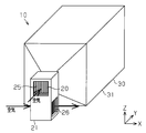
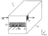
- the perspective view of the battery temperature control apparatus which concerns on one Embodiment of this invention.
- the side view of the battery temperature control apparatus of FIG. The perspective view which shows the structure of the Peltier module of FIG.
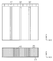
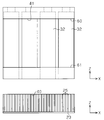
- the front view for demonstrating the flow-path cross-sectional area in the battery temperature control apparatus of FIG. The perspective view of the battery temperature control apparatus of another example.
- the perspective view of the battery temperature control apparatus of another example The side view of the battery temperature control apparatus of another example.
- the horizontal plane is defined by the X and Y directions orthogonal to each other, and the vertical direction is defined by the Z direction.
- the battery temperature adjustment device 10 includes a Peltier module 20 as a thermoelectric conversion module and a battery module 30.
- the Peltier module 20 and the battery module 30 are arranged side by side in the Y direction.
- the Y direction is the direction in which the heat medium (air) for cooling or heating the cylindrical battery 32 of the battery module 30 flows, and the battery module 30 is disposed downstream of the Peltier module 20 in the air flowing direction.
- the Peltier module 20 includes a Peltier element 22 as a thermoelectric conversion element and ceramic plates 23 and 24 shown in FIG. Inside the case 21, a Peltier element 22, ceramic plates 23 and 24, and aluminum fins 25 and 26 as heat conducting members are arranged.
- a ceramic plate 23 is disposed on the first surface (upper surface) of the Peltier element 22, and the Peltier element 22 and the ceramic plate 23 are thermally coupled.
- First fins 25 are provided on the upper surface of the ceramic plate 23. That is, the first fin 25 is provided on one surface of the pair of surfaces of the Peltier module 20.
- the first fin 25 includes a plurality of rectangular plates. The plurality of plates are arranged in parallel with each other with a certain distance therebetween.
- the ceramic plate 23 and the first fin 25 are thermally coupled.
- the first fin 25 is disposed in the first heat medium flow path 40 defined by the case 21, and the first fin 25 extends so that air passes through the flow path between the adjacent first fins 25. Heat is exchanged by sending air in the installation direction (Y direction in FIG. 1). In other words, the first fin 25 is cooled or heated as the Peltier element 22 is energized, and the air as the heat medium is cooled or heated and sent to the battery module 30 downstream.
- the ceramic plate 24 is disposed on the second surface (lower surface) of the Peltier element 22, that is, the surface opposite to the first surface, and the Peltier element 22 and the ceramic plate 24 are thermally coupled.
- Second fins 26 are provided on the lower surface of the ceramic plate 24.
- the second fin 26 includes a plurality of rectangular plates. The plurality of plates are arranged in parallel in a state of being spaced apart by a certain distance.
- the ceramic plate 24 and the second fin 26 are thermally coupled.
- a flow path is formed in the second fin 26, and heat is exchanged by sending air in the extending direction of the plate (X direction in FIG. 1). That is, as the Peltier element 22 is energized, the second fins 26 are heated or cooled, and the air as the heating medium is heated or cooled and sent downstream.
- the air blowing direction to the first fin 25 (Y direction in FIG. 1) and the air blowing direction to the second fin 26 (X direction in FIG. 1) are orthogonal to each other. That is, the two heating media (for example, two airs) are in a crossing flow. Two heat media, for example, two airs are sent to the Peltier module 20 by a fan.
- the ceramic plate 23 and the first fin 25 become heat absorbing members, and the ceramic plate 24 and the second fin 26 become heat generating members.
- the air as the heat medium passing through the first fin 25 is cooled and sent to the battery module 30 downstream. That is, one air is sent to the battery module 30 as air for cooling the battery via the first fins 25, and the other air cools the fins (fins to be heated) 26.
- the fins 25 and 26 are provided in the Peltier module 20 (Peltier element 22), and heat exchange is performed between the heat medium (air) passing through the fins 25 and 26 and the fins 25 and 26.
- the case 31 of the battery module 30 in FIG. 1 has a square box shape. Openings are formed in the side walls of the case 31 that face each other so that air passes through the second refrigerant flow path 41 formed inside the case 31.
- a plurality of cylindrical batteries 32 are fixed upright in the case 31 (see FIG. 4). The batteries 32 are arranged so as to be arranged at intervals along the air flow direction (Y direction) and the width direction of the case 31 (X direction). Air flows between the cylindrical batteries 32 inside the case 31. Air (cold air or hot air) that has passed through the first fins 25 is supplied into the case 31 along the Y direction in FIG. 1, and the cylindrical battery 32 is cooled or cooled by this air (cold air or hot air). Heated.
- heat exchange is performed between the heating medium (air) that has passed through the first fins 25 and the cylindrical battery 32 in the battery module 30.
- the first fins 25 are arranged in the first heat medium flow path 40.
- the second heat medium flow path 41 is located on the downstream side of the first heat medium flow path 40, and the battery 32 is disposed in the second heat medium flow path 41.
- heat exchange is performed between the first fins 25 and the heat medium.
- heat exchange is performed between the battery 32 and the heat medium.
- the flow path cross-sectional area S1 of the first heat medium flow path 40 is smaller than the flow path cross-sectional area S2 of the second heat medium flow path 41.
- the “flow passage cross-sectional area S1 of the first heat medium flow path 40” means the cross-sectional area of the region through which the heat medium flows in the first heat medium flow path 40.
- the case 21 and the ceramic plate 23 is a cross-sectional area of a region defined by 23 and the plurality of fins 25.
- the “flow passage cross-sectional area S2 of the second heat medium flow passage 41” means the cross-sectional area of the region through which the heat medium flows in the second heat medium flow passage 41, and specifically, by the case 31 and the battery 32.
- 5 is a cross-sectional area of a defined area (in FIG. 4, a cross-sectional area of the remaining area excluding an area occupied by the battery 32 from the entire internal area of the case 31).
- the design of the length, shape, pitch, etc. of the fins 25 and 26 provided on one surface (heat absorbing surface) and the other surface (heat radiating surface) of the Peltier element 22 is free.
- the heat transfer area of the second fin 26 is larger than the heat transfer area of the first fin 25.
- the Peltier element 22 is energized. As the Peltier element 22 is energized, the first fin 25 is cooled and the second fin 26 is heated.
- Air is sent to the Peltier module 20 along the Y direction in FIG. Then, heat exchange is performed between the air and the first fin 25, and the air is cooled and sent to the battery module 30 on the downstream side.
- air is sent to the Peltier module 20 along the X direction in FIG. And heat exchange is performed between the air and the 2nd fin 26, and the air which became high temperature passes. That is, on the high temperature side, the second fins 26 are cooled by air.
- the air cooled using the Peltier module 20 flows between the cylindrical batteries 32 in the battery module 30 and exchanges heat with the cylindrical batteries 32 to cool the cylindrical batteries 32. That is, the cylindrical battery 32 is cooled by the air cooled by using the Peltier module 20.
- the flow path cross-sectional area S1 of the first heat medium flow path 40 is smaller than the flow path cross-sectional area S2 of the second heat medium flow path 41.
- the flow rate of the heat medium in the flow path of the first fin 25 provided in the Peltier module 20 becomes larger (faster) than the flow speed of the flow path of the battery 32 in the battery module 30.
- heat exchange between the first fin 25 and the heat medium (air) is efficiently performed.
- the Peltier element 22 is energized in the reverse direction. As the Peltier element 22 is energized, the first fin 25 is heated and the second fin 26 is cooled.
- Air is sent to the Peltier module 20 along the Y direction in FIG. Then, heat exchange is performed between the air and the first fin 25, and the air is heated and sent to the battery module 30 on the downstream side.
- the air heated using the Peltier module 20 flows between the cylindrical batteries 32 in the battery module 30 and exchanges heat with the cylindrical batteries 32 to heat the cylindrical batteries 32.
- the flow path cross-sectional area S1 of the first heat medium flow path 40 is smaller than the flow path cross-sectional area S2 of the second heat medium flow path 41.
- the flow rate of the heat medium in the flow path of the first fin 25 provided in the Peltier module 20 becomes larger (faster) than the flow speed of the flow path of the battery 32 in the battery module 30.
- heat exchange between the first fin 25 and the heat medium (air) is efficiently performed.
- the fins can be shortened by increasing the flow rate of the heat medium, and the apparatus can be downsized.
- the first fin 25 is joined to the ceramic plate 23.
- a location near the base end of the first fin 25 in the standing direction (Z direction) of the first fin 25 mainly takes up heat absorption or heat generation. Even if the length of the fin is increased and the contact area with the heat medium is increased, the portion that contributes to heat absorption or heat generation is closer to the base end of the fin, so that there are more useless portions. As a result, the apparatus becomes large. However, by adopting a configuration that increases the flow velocity as in this embodiment, the fins can be shortened and the apparatus can be downsized.
- the battery temperature control apparatus 10 includes a Peltier module 20 having a pair of surfaces, a first fin 25 provided on one of the pair of surfaces, and a first fin 25 in which the first fin 25 is disposed.
- 1 heat medium flow path 40, and the 2nd heat medium flow path 41 which is located in the downstream of the 1st heat medium flow path 40 and in which the battery 32 is arrange
- the flow path cross-sectional area that is the cross-sectional area of the region through which the heat medium flows is smaller than the flow path cross-sectional area that is the cross-sectional area of the region in which the heat medium flows in the second heat medium flow path 41.
- the embodiment is not limited to the above, and may be embodied as follows, for example.
- the shape of the Peltier module 20 is arbitrary.
- the Peltier module 20 may be made smaller than the Peltier module 20 of FIG. Thereby, the flow channel area can be further reduced (for example, half).
- the direction and position of the flow path are arbitrary.
- the air passing through the first fin 25 on the lower side with the vertical positions of the fins 25 and 26 reversed from the vertical positions of the fins 25 and 26 in FIG. May be supplied.
- the directions of the flow paths of the fins 25 and 26 may be the same. That is, as shown in FIGS. 6 and 7, the refrigerant may flow only in the Y direction. Further, as shown in FIG. 8, the directions of the flow paths of the fins 25 and 26 may be crossed.
- the Peltier module and the battery module are separated, but as shown in FIG. 9, the Peltier module and the battery module may be integrated. That is, a battery, a Peltier element, a fin, and the like may be housed in the common case 50. In this way, the number of parts can be reduced by using the integrated type.
- the flow path 41 may be partitioned by partition plates 60 and 61. As a result, the heat medium can be passed through a part of the flow path 41.
- the present invention may be implemented as shown in FIG. That is, the Peltier module (Peltier element) 82 may be disposed around the inlet pipe 81 of the case 80 that houses the battery 32, and the fin 83 may be disposed in the inlet pipe 81.
- the Peltier module Peltier element
- the battery to be temperature controlled may be a single battery or a modular battery.
- the temperature-controlled battery is not limited to a cylindrical battery, and may be a square battery, for example.
- Thermoelectric conversion elements may be other than Peltier elements.
- the present invention is embodied in a vehicle equipped with a battery for traveling.
- the present invention is not limited to this.
- the present invention may be embodied in a battery temperature control device for home use.
Landscapes
- Engineering & Computer Science (AREA)
- Manufacturing & Machinery (AREA)
- Chemical & Material Sciences (AREA)
- Chemical Kinetics & Catalysis (AREA)
- Electrochemistry (AREA)
- General Chemical & Material Sciences (AREA)
- Physics & Mathematics (AREA)
- Electromagnetism (AREA)
- Secondary Cells (AREA)
Abstract
熱電変換モジュールと、熱伝導部材と、第1熱媒流路と、第2熱媒流路とを備える電池温調装置が開示される。熱電変換モジュールは一対の面を有する。熱伝導部材は一対の面のうちの一方に設けられる。第1熱媒流路の内部には、熱伝導部材が配置される。第2熱媒流路は、第1熱媒流路の下流側に位置し、電池が内部に配置される。第1熱媒流路の流路断面積は、第2熱媒流路の流路断面積より小さい。
Description
本発明は、電池温調装置に関する。
特許文献1に開示の蓄電池の温度調節装置は、熱電モジュールもしくは熱電モジュールと同じ特性を有する熱電素子チップ等の熱電変換デバイスを備えている。熱電変換デバイスは第1の面及び第2の面を有し、同第1の面及び第2の面は通電の極性に応じて相反する作用、すなわち放熱と吸熱とをする。第1の面を1つまたは複数の蓄電池と熱結合するとともに、第2の面をその面の熱作用を促進する熱作用促進媒体と熱結合している。
ところで、更なる熱交換の効率の向上を図りたいというニーズがある。
本発明の目的は、熱媒の流路における電池の上流側に配した熱伝導部材と熱媒との熱交換効率を向上させることができる電池温調装置を提供することにある。
上記目的を達成するため、本発明の一態様では、熱電変換モジュールと、熱伝導部材と、第1熱媒流路と、第2熱媒流路とを備える電池温調装置が提供される。前記熱電変換モジュールは一対の面を有する。前記熱伝導部材は前記一対の面のうちの一方に設けられる。前記第1熱媒流路の内部には、前記熱伝導部材が配置される。前記第2熱媒流路は、前記第1熱媒流路の下流側に位置し、電池が内部に配置される。前記第1熱媒流路の流路断面積は前記第2熱媒流路の流路断面積より小さい。
上記構成によれば、第1熱媒流路において熱電変換モジュールの一対の面のうちの一方に設けた熱伝導部材が内部に配置され、熱媒と熱伝導部材との間で熱交換が行われる。第2熱媒流路は第1熱媒流路の下流側に連通し、電池が内部に配置され、熱媒と電池との間で熱交換が行われる。
ここで、第1熱媒流路の流路断面積が第2熱媒流路の流路断面積より小さくなっているので、熱媒の流路における電池の上流側に配した第1熱媒流路において流速が速くなる。そのため、第1熱媒流路に配した熱伝導部材と熱媒との熱交換効率を向上させることができる。
好ましくは、前記第1熱媒流路の流路断面積は前記第1熱媒流路において熱媒の流れる領域の断面積であり、前記第2熱媒流路の流路断面積は前記第2熱媒流路において熱媒の流れる領域の断面積である。
上記構成によれば、第1熱媒流路において熱媒の流れる領域の断面積である流路断面積が、第2熱媒流路において熱媒の流れる領域の断面積である流路断面積より小さい。これにより、熱媒の流路における電池の上流側に配した第1熱媒流路において流速が早くなる。そのため第1のフィンと熱媒との熱交換効率を向上させることができる。
好ましくは、前記熱伝導部材はフィンである。
上記構成によれば、熱伝導部材はフィンであるので、伝熱面積を大きくすることができる。
以下、本発明を、走行用電池を搭載した車両(自動車)に具体化した一実施形態を図面に従って説明する。
なお、図面において、水平面を、互いに直交するX,Y方向で規定するとともに、上下方向をZ方向で規定している。
図1,2に示すように、電池温調装置10は、熱電変換モジュールとしてのペルチェモジュール20と、電池モジュール30とを備えている。ペルチェモジュール20と電池モジュール30とがY方向に並べて配置されている。Y方向が電池モジュール30の円筒形電池32の冷却または加熱のための熱媒(空気)の流れる方向であり、空気の流れる方向においてペルチェモジュール20の下流側に電池モジュール30が配置されている。
ペルチェモジュール20は、図3に示す熱電変換素子としてのペルチェ素子22と、セラミック板23,24とを備えている。ケース21の内部に、ペルチェ素子22と、セラミック板23,24と、熱伝導部材としてのアルミ製のフィン25,26とが配置されている。
ペルチェ素子22の第1の面(上面)にはセラミック板23が配置され、ペルチェ素子22とセラミック板23とは熱的に結合している。セラミック板23の上面には第1のフィン25が設けられている。即ち、ペルチェモジュール20の一対の面のうちの片方の面に第1のフィン25が設けられている。第1のフィン25は、複数の長方形の板を含む。複数の板は一定の距離をおいて離間した状態で互いに平行に配置されている。セラミック板23と第1のフィン25とは熱的に結合している。第1のフィン25はケース21によって画定された第1熱媒流路40内に配置され、隣り合う第1のフィン25の間の流路を空気が通過するよう、第1のフィン25の延設方向(図1のY方向)に空気が送られて熱交換が行われる。つまり、ペルチェ素子22の通電に伴い第1のフィン25が冷却または加熱され、熱媒としての空気が冷却または加熱されて下流の電池モジュール30に送られる。
ペルチェ素子22の第2の面(下面)、すなわち前記第1の面とは反対側の面にはセラミック板24が配置され、ペルチェ素子22とセラミック板24とは熱的に結合している。セラミック板24の下面には第2のフィン26が設けられている。第2のフィン26は、複数の長方形の板を含む。複数の板は一定の距離をおいて離間した状態で平行に配置されている。セラミック板24と第2のフィン26とは熱的に結合している。第2のフィン26には流路が形成されており、板の延設方向(図1のX方向)に空気が送られて熱交換が行われる。つまり、ペルチェ素子22の通電に伴い第2のフィン26が加熱または冷却され、熱媒としての空気が加熱または冷却されて下流に送られる。
第1のフィン25への空気の送風方向(図1のY方向)と第2のフィン26への空気の送風方向(図1のX方向)とは直交している。即ち、2つの熱媒(例えば2つの空気)は交差する流れとなっている。なお、2つの熱媒、例えば2つの空気はファンにてペルチェモジュール20に送られる。
そして、ペルチェ素子22に第1の方向に沿った電流を流すと、セラミック板23および第1のフィン25が吸熱部材となるとともにセラミック板24および第2のフィン26が発熱部材となる。この通電に伴い第1のフィン25を通過する熱媒としての空気が冷却されて下流の電池モジュール30に送られる。つまり、一方の空気は第1のフィン25を経て電池を冷却するための空気として電池モジュール30に送られ、他方の空気はフィン(高温化されるフィン)26を冷ます。
一方、ペルチェ素子22に第1の方向と逆の第2の方向に沿った電流を流すと、セラミック板23および第1のフィン25が発熱部材となるとともにセラミック板24および第2のフィン26が吸熱部材となる。この通電に伴い第1のフィン25を通過する熱媒としての空気が加熱されて下流の電池モジュール30に送られる。
このようにして、ペルチェモジュール20(ペルチェ素子22)にフィン25,26が設けられ、フィン25,26を通過する熱媒(空気)とフィン25,26との間で熱交換が行われる。
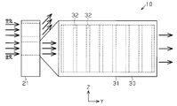
図1の電池モジュール30のケース31は四角箱型をなしている。ケース31の内部に形成された第2冷媒流路41を空気が通過するように、ケース31の互いに対向する側壁にはそれぞれ開口部が形成されている。ケース31の内部には複数本の円筒形電池32が立設された状態で固定されている(図4参照)。電池32は空気の流れ方向(Y方向)及びケース31の幅方向(X方向)それぞれに沿って間隔をおいて並ぶように配置されている。ケース31の内部において円筒形電池32の間を空気が流れる。ケース31の内部には、第1のフィン25を通過した空気(冷風または温風)が図1のY方向に沿って供給され、この空気(冷風または温風)により円筒形電池32が冷却または加熱される。
このようにして、電池モジュール30において第1のフィン25を通過した熱媒(空気)と円筒形電池32との間で熱交換が行われる。
図4に示すように、第1熱媒流路40内には、第1のフィン25が配置される。また、第2熱媒流路41は第1熱媒流路40の下流側に位置し、同第2熱媒流路41内には電池32が配置される。第1熱媒流路40を熱媒が通過することに伴って第1のフィン25と熱媒との間で熱交換が行われる。第2熱媒流路41を熱媒が通過することに伴って電池32と熱媒との間で熱交換が行われる。第1熱媒流路40の流路断面積S1が第2熱媒流路41の流路断面積S2より小さくなっている。これにより、ペルチェモジュール20に設けた第1のフィン25と熱媒(空気)との熱交換が効率的に行われる。なお、「第1熱媒流路40の流路断面積S1」とは、第1熱媒流路40において熱媒の流れる領域の断面積を意味し、具体的には、ケース21とセラミック板23と複数のフィン25とによって画定される領域の断面積である。「第2熱媒流路41の流路断面積S2」とは、第2熱媒流路41において熱媒の流れる領域の断面積を意味し、具体的には、ケース31と電池32とによって画定される領域の断面積(図4において、ケース31の内部領域全体から電池32が占める領域を除いた残りの領域の断面積)である。
なお、ペルチェ素子22における一方の面(吸熱面)、他方の面(放熱面)に設けるフィン25,26の長さ、形状、ピッチ等の設計は自由である。本実施形態では、第2のフィン26の伝熱面積を第1のフィン25の伝熱面積よりも大きくしている。
次に、このように構成した電池温調装置10の作用を説明する。
まず、電池モジュール30の円筒形電池32を冷却する場合について説明する。
ペルチェモジュール20においてペルチェ素子22が通電される。ペルチェ素子22の通電に伴い第1のフィン25が冷却されるとともに第2のフィン26が加熱される。
空気がペルチェモジュール20に対し図1のY方向に沿って送られてくる。そして、その空気と第1のフィン25との間で熱交換が行われて、空気が冷やされて下流側の電池モジュール30に送られる。
また、ペルチェモジュール20に対し図1のX方向に沿って空気が送られてくる。そして、その空気と第2のフィン26との間で熱交換が行われて、高温となった空気が通過していく。即ち、高温側では空気により第2のフィン26が冷却される。
ペルチェモジュール20を用いて冷却された空気は電池モジュール30において円筒形電池32の間を流れて円筒形電池32と熱交換されて円筒形電池32を冷却する。即ち、ペルチェモジュール20を用いて冷やされた空気によって円筒形電池32が冷却される。
ここで、第1熱媒流路40の流路断面積S1が第2熱媒流路41の流路断面積S2より小さくなっている。これにより、ペルチェモジュール20に設けた第1のフィン25の流路における熱媒の流速が電池モジュール30における電池32の流路における流速よりも大きくなる(速くなる)。その結果、第1のフィン25と熱媒(空気)との熱交換が効率的に行われる。
次に、電池モジュール30の円筒形電池32を加熱する場合について説明する。
ペルチェモジュール20においてペルチェ素子22が逆向きに通電される。ペルチェ素子22の通電に伴い第1のフィン25が加熱されるとともに第2のフィン26が冷却される。
空気がペルチェモジュール20に対し図1のY方向に沿って送られてくる。そして、その空気と第1のフィン25との間で熱交換が行われて、空気が加熱されて下流側の電池モジュール30に送られる。
また、空気がペルチェモジュール20に対し図1のX方向に沿って送られてくる。そして、その空気と第2のフィン26との間で熱交換が行われて、低温となった空気がペルチェモジュール20を通過していく。
ペルチェモジュール20を用いて加熱された空気は電池モジュール30において円筒形電池32の間を流れて円筒形電池32と熱交換されて円筒形電池32を加熱する。
ここで、第1熱媒流路40の流路断面積S1が第2熱媒流路41の流路断面積S2より小さくなっている。これにより、ペルチェモジュール20に設けた第1のフィン25の流路における熱媒の流速が電池モジュール30における電池32の流路における流速よりも大きくなる(速くなる)。その結果、第1のフィン25と熱媒(空気)との熱交換が効率的に行われる。
第1のフィン25と熱媒との熱交換において、第1のフィン25と熱媒との接触面積を大きくする、あるいは、熱媒の流速を速くすることにより多くの熱を交換することができる。本実施形態では、熱媒の流速を速くすることによりフィンを短くでき装置の小型化を図ることができる。
詳しく説明する。第1のフィン25はセラミック板23と接合される。第1のフィン25の立設方向(Z方向)における第1のフィン25の基端寄りの箇所(セラミック板23との接合部近傍)が主に吸熱または発熱を担っている。フィンの長さを長くして熱媒との接触面積を増やしたとしても吸熱または発熱に寄与する部位はフィンの基端寄りの箇所であるため無駄な部位が多くなる。その結果、装置が大型化してしまう。しかしながら、本実施形態のように流速を速くするような構成を採用することによりフィンを短くでき装置の小型化を図ることができる。
以上のごとく本実施形態によれば、以下のような利点を得ることができる。
(1)電池温調装置10は、一対の面を有するペルチェモジュール20と、一対の面のうちの一方に設けた第1のフィン25と、前記第1のフィン25が内部に配置される第1熱媒流路40と、第1熱媒流路40の下流側に位置し、電池32が内部に配置される第2熱媒流路41と、を備える。第1熱媒流路40において熱媒の流れる領域の断面積である流路断面積が、第2熱媒流路41において熱媒の流れる領域の断面積である流路断面積より小さい。これにより、熱媒の流路における電池32の上流側に配した第1熱媒流路40において流速が早くなる。そのため第1のフィン25と熱媒との熱交換効率を向上させることができる。
(2)熱伝導部材はフィンであるので、伝熱面積を大きくすることができる。
(3)ペルチェモジュールと電池モジュールとが、別体であるので、とりまわしがしやすい。また、ペルチェモジュールと電池モジュールとの組み合わせをいろいろなものにすることができる。
実施形態は前記に限定されるものではなく、例えば、次のように具体化してもよい。
ペルチェモジュール20の形状は任意である。例えば図5に示すように、図1のペルチェモジュール20に比べペルチェモジュール20をより小さくしてもよい。これにより流路面積を更に小さく(例えば半分)することができる。
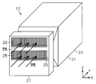
流路の向きや位置は任意である。例えば、図6,7に示すように、フィン25,26の上下位置を、図1におけるフィン25,26の上下位置と逆にして下側の第1のフィン25を通過した空気を電池モジュール30に供給してもよい。また、この場合、図6,7に示すように、フィン25,26の流路の向きを同一にしてもよい。つまり、図6,7に示すように、冷媒は共にY方向にのみ流されてもよい。また、図8に示すように、フィン25,26の流路の向きを交差させてもよい。
上記実施形態ではペルチェモジュールと電池モジュールとは分離していたが、図9に示すように、ペルチェモジュールと電池モジュールとを一体化してもよい。即ち、共通のケース50内に電池、ペルチェ素子、及びフィン等を収納してもよい。このように一体型とすることにより、部品点数を減らすことができる。
図4に対応する図10に示すように、流路41を仕切り板60,61で仕切ってもよい。これにより流路41の一部に熱媒を通過させることができる。
本発明は図11に示すように実施してもよい。すなわち、電池32を収納するケース80の入口パイプ81の周辺にペルチェモジュール(ペルチェ素子)82を配置し、入口パイプ81内にフィン83を配置してもよい。
温調対象の電池は、単体でもモジュール化されたものでもよい。
温調対象の電池は、円筒形電池に限ることなく、例えば角形電池等でもよい。
熱電変換素子はペルチェ素子以外でもよい。
上記実施形態では本発明を走行用電池を搭載した車両に具体化したが、これに限ることなく、例えば家庭用の電池温調装置に具体化してもよい。
Claims (3)
- 一対の面を有する熱電変換モジュールと、
前記一対の面のうちの一方に設けた熱伝導部材と、
前記熱伝導部材が内部に配置される第1熱媒流路と、
前記第1熱媒流路の下流側に位置し、電池が内部に配置される第2熱媒流路と、
を備え、
前記第1熱媒流路の流路断面積が前記第2熱媒流路の流路断面積より小さい電池温調装置。 - 前記第1熱媒流路の流路断面積は前記第1熱媒流路において熱媒の流れる領域の断面積であり、前記第2熱媒流路の流路断面積は前記第2熱媒流路において熱媒の流れる領域の断面積である、請求項1に記載の電池温調装置。
- 前記熱伝導部材はフィンである請求項1に記載の電池温調装置。
Applications Claiming Priority (2)
| Application Number | Priority Date | Filing Date | Title |
|---|---|---|---|
| JP2011054587 | 2011-03-11 | ||
| JP2011-054587 | 2011-03-11 |
Publications (1)
| Publication Number | Publication Date |
|---|---|
| WO2012124479A1 true WO2012124479A1 (ja) | 2012-09-20 |
Family
ID=46830554
Family Applications (1)
| Application Number | Title | Priority Date | Filing Date |
|---|---|---|---|
| PCT/JP2012/055090 Ceased WO2012124479A1 (ja) | 2011-03-11 | 2012-02-29 | 電池温調装置 |
Country Status (1)
| Country | Link |
|---|---|
| WO (1) | WO2012124479A1 (ja) |
Citations (3)
| Publication number | Priority date | Publication date | Assignee | Title |
|---|---|---|---|---|
| JPH0993834A (ja) * | 1995-09-26 | 1997-04-04 | Nippon Telegr & Teleph Corp <Ntt> | 無停電電源システム |
| JP2010192207A (ja) * | 2009-02-17 | 2010-09-02 | Mitsubishi Heavy Ind Ltd | 電池用冷却装置及び組電池 |
| JP2010532066A (ja) * | 2007-04-04 | 2010-09-30 | エスケー エナジー 株式会社 | 熱電半導体素子を用いた電気自動車のバッテリー温度調節装置 |
-
2012
- 2012-02-29 WO PCT/JP2012/055090 patent/WO2012124479A1/ja not_active Ceased
Patent Citations (3)
| Publication number | Priority date | Publication date | Assignee | Title |
|---|---|---|---|---|
| JPH0993834A (ja) * | 1995-09-26 | 1997-04-04 | Nippon Telegr & Teleph Corp <Ntt> | 無停電電源システム |
| JP2010532066A (ja) * | 2007-04-04 | 2010-09-30 | エスケー エナジー 株式会社 | 熱電半導体素子を用いた電気自動車のバッテリー温度調節装置 |
| JP2010192207A (ja) * | 2009-02-17 | 2010-09-02 | Mitsubishi Heavy Ind Ltd | 電池用冷却装置及び組電池 |
Similar Documents
| Publication | Publication Date | Title |
|---|---|---|
| JP4303679B2 (ja) | 熱交換装置 | |
| JP2009152440A (ja) | 発熱体の温度調整装置 | |
| CN106907760B (zh) | 散热组件及电热油汀 | |
| RU2008129540A (ru) | Устройство испарительного охлаждения | |
| JP2011134979A5 (ja) | ||
| JP2015535070A (ja) | 空気熱交換器間に配置された液体熱交換器を含む熱電冷却デバイス | |
| KR20170011156A (ko) | 열전소자를 이용하는 모듈화된 발전장치 | |
| CN108307607A (zh) | 具有热电冷却元件的进气通道 | |
| KR20150075122A (ko) | 열전소자가 구비된 열교환기 | |
| JP2015156347A (ja) | バッテリ温調装置 | |
| JP2012195209A (ja) | 電池温調装置 | |
| JP5381328B2 (ja) | 熱電ユニット | |
| JP2016025271A (ja) | 熱電変換装置 | |
| KR20120107867A (ko) | 히트 펌프 시스템 | |
| JP5906921B2 (ja) | 電池モジュール及び車両 | |
| WO2012165252A1 (ja) | 蓄電装置 | |
| CN102620466A (zh) | 空调芯 | |
| JP2012195210A (ja) | 電池温調装置 | |
| JP2013084475A (ja) | 電池用温調機構 | |
| JP2011195066A (ja) | 熱交換装置及び車両用空調装置 | |
| JP2013098082A (ja) | 電池用温度調節機構 | |
| JP2013145830A (ja) | 電子機器用液冷システムにおけるラジエータ | |
| WO2016098679A1 (ja) | 熱電発電ユニット、それを用いた熱電発電装置およびその取付構造、その取付構造を有する排気ダクトならびにエンジン | |
| JP7830033B2 (ja) | 面接触型熱交換器 | |
| JP2013114926A (ja) | 電池用熱交換器及び車両 |
Legal Events
| Date | Code | Title | Description |
|---|---|---|---|
| 121 | Ep: the epo has been informed by wipo that ep was designated in this application |
Ref document number: 12758233 Country of ref document: EP Kind code of ref document: A1 |
|
| NENP | Non-entry into the national phase |
Ref country code: DE |
|
| 122 | Ep: pct application non-entry in european phase |
Ref document number: 12758233 Country of ref document: EP Kind code of ref document: A1 |
|
| NENP | Non-entry into the national phase |
Ref country code: JP |