WO2012124356A1 - 電子体温計、受信装置、および測定値の転送方法 - Google Patents
電子体温計、受信装置、および測定値の転送方法 Download PDFInfo
- Publication number
- WO2012124356A1 WO2012124356A1 PCT/JP2012/050178 JP2012050178W WO2012124356A1 WO 2012124356 A1 WO2012124356 A1 WO 2012124356A1 JP 2012050178 W JP2012050178 W JP 2012050178W WO 2012124356 A1 WO2012124356 A1 WO 2012124356A1
- Authority
- WO
- WIPO (PCT)
- Prior art keywords
- electronic thermometer
- audio signal
- measurement value
- value
- receiving device
- Prior art date
- Legal status (The legal status is an assumption and is not a legal conclusion. Google has not performed a legal analysis and makes no representation as to the accuracy of the status listed.)
- Ceased
Links
Images





Classifications
-
- H—ELECTRICITY
- H04—ELECTRIC COMMUNICATION TECHNIQUE
- H04Q—SELECTING
- H04Q9/00—Arrangements in telecontrol or telemetry systems for selectively calling a substation from a main station, in which substation desired apparatus is selected for applying a control signal thereto or for obtaining measured values therefrom
-
- G—PHYSICS
- G01—MEASURING; TESTING
- G01K—MEASURING TEMPERATURE; MEASURING QUANTITY OF HEAT; THERMALLY-SENSITIVE ELEMENTS NOT OTHERWISE PROVIDED FOR
- G01K13/00—Thermometers specially adapted for specific purposes
- G01K13/20—Clinical contact thermometers for use with humans or animals
-
- H—ELECTRICITY
- H04—ELECTRIC COMMUNICATION TECHNIQUE
- H04Q—SELECTING
- H04Q2209/00—Arrangements in telecontrol or telemetry systems
- H04Q2209/40—Arrangements in telecontrol or telemetry systems using a wireless architecture
Definitions
- the present invention relates to an electronic thermometer, a receiver, and a measurement value transfer method, and more particularly to an electronic thermometer, a receiver, and a measurement value transfer method having a function of communicating a measurement value using sound.
- body temperature which is basic biological information of each patient, is periodically measured and recorded as a graph on a medical chart to observe a trend and grasp a metabolic state.
- thermometer In temperature management in medical facilities, it is common practice for nurses or patients themselves to measure body temperature using a thermometer and manually record the measured values on a medical chart.
- Patent Document 1 Japanese Patent Laid-Open No. 2000-283855
- a thermometer with a display device that blinks in accordance with a measured value, and displays the measured value on the display device so that the light receiving element can read the measured value.
- the technology is disclosed.
- thermometer needs to be equipped with a function for blinking in accordance with the measured value, so that the thermometer becomes large or expensive. .
- An object of the present invention is to provide an electronic thermometer, a receiving device, and a measurement device that enable accurate measurement value communication without suppressing the size and cost of the device itself and without complicating the operation of the user. It is to provide a method for transferring values.
- an electronic thermometer is an electronic thermometer that measures the temperature of a measurement site of a subject and outputs a measurement value, the temperature sensor, a sounding device, and a control connected to the temperature sensor and the sounding device.
- the control device as control to output the measurement value using the sound generation device, a process of calculating the temperature of the measurement site as a measurement value based on the sensor signal from the temperature sensor, a process of converting the measurement value into an audio signal, And a process for outputting an audio signal from the sound generation device.
- the electronic thermometer further includes an instruction unit for instructing the output of the measurement value, and the control device is also connected to the instruction unit, and executes the above control in accordance with an instruction from the instruction unit.
- the process of converting the measurement value into an audio signal includes a step of converting the measurement value into a binary value and a step of generating an audio signal by assigning audio ON / OFF to each of the binary values.
- the audio signal is output from the sounding device at a predetermined output speed.
- the receiving device is a receiving device for receiving a measurement value from an electronic thermometer, and the electronic thermometer converts the measurement value into an audio signal and outputs an audio signal.
- a microphone and a control device connected to the microphone.
- the control device executes a process of converting the audio signal input from the microphone into a measurement value and a process of outputting the measurement value by a conversion method corresponding to a method of converting the audio signal from the measurement value of the electronic thermometer.
- a sound signal is generated by assigning sound ON / OFF to each binary value obtained by converting the measurement value into a binary value, and the sound is generated at a predetermined output speed.
- the process of outputting a signal and converting an audio signal into a measurement value is performed based on a step of generating a pulse signal based on the audio signal and a pulse signal based on an interval between the pulse signal and a predetermined output speed. Converting the signal into a binary value and identifying the measured value by converting the binary value into a decimal value.
- control device further executes a process of extracting the audio signal output from the electronic thermometer by extracting the frequency band of the audio signal output from the electronic thermometer from the audio signal input from the microphone.
- the receiving device includes a storage unit for storing the electronic thermometer, and an instruction unit for instructing the electronic thermometer to output a measurement value when the electronic thermometer is stored in the storage unit. And further comprising.
- the electronic thermometer has a button for instructing the output of the measurement value, and the instruction unit is provided in the storage unit at a position where the electronic thermometer is in contact with the button in a state of being stored in the storage unit. It is a protrusion.
- the electronic thermometer has a speaker for outputting an audio signal, and the microphone is provided in the vicinity of the speaker when the electronic thermometer is stored in the storage unit.
- a measured value transfer method includes an electronic thermometer that measures a temperature of a measurement site of a subject and outputs the measured value, and a receiving device that receives the measured value from the electronic thermometer.
- a method of transferring measured values in a system including a step of calculating the temperature of a measurement site as a measured value with an electronic thermometer, converting the measured value into an audio signal with an electronic thermometer, and an audio signal from a sound generator included in the electronic thermometer A step of outputting an audio signal with a microphone included in the receiving device, and a conversion method corresponding to a method of converting the audio signal input with the microphone from the measurement value of the electronic thermometer with the receiving device And converting the measurement value into a measurement value and outputting the measurement value obtained in the conversion step from the receiving device.
- the present invention it is possible to accurately transmit a measured value from the electronic thermometer to the receiving device without increasing the size and cost of the electronic thermometer and complicating the operation of the user.
- FIG. 1 It is a figure which shows the specific example of a structure of the body temperature management system concerning embodiment. It is a figure which shows schematic structure of the electronic thermometer contained in a body temperature management system. It is the figure which looked at the main part of an electronic thermometer from the end by the side in which the 1st switch was provided. It is a figure which shows the outline of an internal structure of the receiver included in a body temperature management system. It is a functional block diagram of an electronic thermometer. It is a control block diagram of the electronic thermometer for transmitting a measured value to a receiver. It is a figure for demonstrating the audio
- FIG. 1 is a diagram showing a specific example of the configuration of the body temperature management system according to the present embodiment.
- a body temperature management system includes an electronic thermometer 1 for measuring a body temperature of a measurement subject, and a receiving device 3 for receiving a measurement value transmitted from the electronic thermometer 1 with the electronic thermometer 1. And a processing device 2 that is equipped with management software such as an electronic medical record, receives measurement values transmitted from the reception device 3, and writes the measurement values in a memory (not shown) managed by the management software. .
- the receiving device 3 has a storage portion 32 (FIG. 4) for inserting and setting the electronic thermometer 1, and the electronic thermometer 1 is set in the storage portion 32 by inserting the electronic thermometer 1 from the insertion port 31.
- the measurement value of the electronic thermometer 1 is transferred to the receiving device 3.
- the receiving device 3 and the processing device 2 are electrically connected via a network 7 such as the Internet or a LAN (Local Area Network).
- the measurement value may be transmitted directly from the reception device 3 to the processing device 2 using wireless communication or the like without using the network 7.
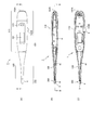
- FIG. 2 is a diagram illustrating a schematic configuration of the electronic thermometer 1.
- 2A is a front view of the electronic thermometer 1
- FIG. 2B is a cross-sectional view along AA in FIG. 2A
- FIG. 2C is FIG. 2B. It is BB sectional drawing of.
- an electronic thermometer 1 includes a housing 100 having a hollow structure inside.
- the housing 100 is sandwiched between a substantially rectangular parallelepiped main body 110 provided with a display unit 101, a speaker 103 as an information output unit, switches 102A and 102B, and a measurement site such as a user's armpit, sublingual, rectum.
- a temperature measuring unit 300 for measuring the temperature of the measurement site of the user is provided.
- the housing 100 contains an internal component 4 composed of a circuit board, a power source, and the like.
- the probe unit 120 is a tapered rod-like member that extends from one end of the substantially rectangular parallelepiped main body 110 and supports the temperature measuring unit 300 with respect to the main body 110 and has a hollow structure inside.
- the axial direction in which the probe unit 120 extends is also referred to as “longitudinal direction”.
- a display unit 101 and a speaker 103 are provided on a surface parallel to the longitudinal direction of the main body unit 110.
- the display unit 101 and the speaker 103 are not necessarily provided on the same surface.
- the surface of the main body 110 on which at least the display unit 101 is provided is referred to as “front”.
- the temperature measuring unit 300 at the tip of the probe unit 120 includes a cap 5 made of stainless steel (SUS: Steel Use Stainless) or the like, and the inside of the cap 5. And a temperature sensor 6 such as a thermistor that is embedded and fixed in the housing.
- the temperature sensor 6 is connected to a CR oscillation circuit (an oscillation circuit using a capacitor and a resistor) of the internal component 4 by a lead wire 41 extending through the hollow interior of the probe unit 120 from the internal component 4 accommodated in the housing 100. Electrically connected.
- the temperature sensor 6 changes the resistance value according to the heat transmitted from the outer surface of the temperature measuring unit 300, and the change in the resistance value is output to the CR oscillation circuit.
- the example in which the probe part 120 and the temperature measuring part 300 are formed separately by using the cap 5 is shown.
- the cap 5 may not be used and the resin-molded main body 110 and the probe 120 may be integrally molded.
- the main body 110, the probe part 120, and the temperature measuring part 300 constitute the housing 100.
- the main body 110 has a first switch 102A, which is an ON / OFF switch for instructing the start and end of measurement, and a second switch, which is a switch for instructing the start of measurement value communication with the receiving device 3.
- a switch 102B is provided.
- the first switch 102A is provided at the end opposite to the side on which the probe unit 120 and the temperature measuring unit 300 are provided, and the second switch 102B is provided on the first switch 102A.
- the example provided in the surface different from all the surfaces of an edge part, a front surface, and a surface parallel to a front surface, ie, a side surface, is shown.
- the positional relationship of these switches is not limited to the positional relationship shown in FIG.
- the second switch 102 ⁇ / b> B may be provided on the front surface of the main body 110.
- the first switch 102 ⁇ / b> A may be provided on the side surface of the main body 110.
- the first switch 102A and the second switch 102B are preferably configured not to be provided on the same plane.
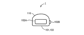
- FIG. 3 is a view of the main body 110 viewed from the end opposite to the side on which the probe 120 and the temperature measuring section 300 are provided, that is, the view from the end on the side where the first switch 102A is provided. is there.
- the cross-sectional shape of main body 110 has a shape in which a front surface is a substantially flat surface and a surface opposite to the front surface is an arc.
- FIG. 3 is merely an example, and may preferably be another shape as long as the front surface and the opposite side, or both side surfaces have different shapes.
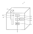
- FIG. 4 is a diagram showing an outline of the internal configuration of the receiving device 3. With reference to FIG. 4, it has the accommodating part 32 provided in the direction which goes to the inside of a housing
- the cross-section of the insertion port 31 is similar to the cross-sectional shape of the main body 110 of the electronic thermometer 1 shown in FIG. 3, and has a size that cannot be inserted with the surface of the electronic thermometer 1 facing the arc-shaped surface. To do.
- the electronic thermometer 1 is inserted in the axial direction from the insertion port 31 toward the inside of the housing, the electronic thermometer 1 is inserted in a direction corresponding to the cross section of the insertion port 31.
- the storage part 32 has a taper-like shape having a longitudinal direction from the insertion port 31 toward the inside of the housing and a hollow structure inside.
- the tapered shape matches the shape of the probe portion 120 of the electronic thermometer 1. Accordingly, when the electronic thermometer 1 is inserted in the axial direction from the insertion port 31 toward the inside of the housing, the probe unit 120 is located at a position in the storage unit 32 where the shape of the probe unit 120 and the tapered shape coincide with each other. As a result, the position of the electronic thermometer 1 relative to the receiving device 3 in the longitudinal direction is held constant.
- a protrusion 32 ⁇ / b> A is provided on the inner wall of the storage portion 32.
- the protrusion 32A has the electronic thermometer 1 inserted into the storage portion 32 in a direction corresponding to the cross section of the insertion port 31, and the probe portion 120 is held at a position where the shape of the probe portion 120 and the tapered shape coincide with each other. It is provided at a position where it touches the second switch 102B of the electronic thermometer 1 and depresses the second switch 102B.
- the protrusion 32A is provided in a form corresponding to the position and operation method of the second switch 102B. That is, the shape is not limited to the simple protrusion shape as shown in FIG. 4, and when the second switch 102B is a slide type, the second switch 102B has a concave shape. If the depression is to be pushed down, a convex shape that matches the depression is used.
- the second switch 102B can be configured by simply inserting the electronic thermometer 1 into the storage unit 32 of the receiving device 3 without performing a special operation such as a user pressing down the second switch 102B. It will be pressed automatically.
- the electronic thermometer 1 is set in the receiving device 3 because the cross section of the insertion port 31 and the shape of the storage portion 32 are the above-described shapes, the state of the electronic thermometer 1 in the receiving device 3 is indicated by the second switch 102B. It can be in a state of being pressed by the protrusion 32A.
- reception device 3 is executed by a microphone 33, a CPU (Central Processing Unit) 30 that is electrically connected to microphone 33 and performs overall control, and CPU 30.
- a memory 34 for storing the program, and a communication unit 35 for outputting a measurement value obtained as a result of processing by the CPU 30 to the processing device 2 via the network 7 are included.
- the CPU 30 performs an operation for analyzing the audio signal input from the microphone 33 and acquiring the measurement value.
- the microphone 33 is preferably configured such that the electronic thermometer 1 is inserted into the storage portion 32 in a direction corresponding to the cross section of the insertion port 31, and the probe portion 120 is held at a position where the shape of the probe portion 120 matches the tapered shape. It is provided at a position near the speaker 103 provided in the electronic thermometer 1 in the state. By arranging in this way, sound is collected by the microphone 33 even if the loud sound is not output from the speaker 103 of the electronic thermometer 1. Furthermore, since the sound emitted from the speaker 103 while being stored in the storage unit 32 is collected by the microphone 33, it is possible to prevent deterioration in communication quality due to the influence of noise.
- FIG. 5 is a functional block diagram of the electronic thermometer 1.
- the electronic thermometer 1 includes a control unit 12, a memory unit 13, a display unit 101, switches 102A and 102B, a speaker 103, a power supply unit 17, a temperature sensor 6 as functional blocks.
- the control unit 12 is configured by, for example, a CPU mounted on the circuit board of the internal component 4 and controls the entire electronic thermometer 1.
- the memory unit 13 is configured by, for example, a ROM (Read-Only Memory) or a RAM (Random-Access Memory) included in the internal component 4, and a program for causing the control unit 12 to execute a processing procedure for body temperature measurement. Is used for storing the measurement results and the measurement results.
- the display unit 101 is configured by a display panel such as an LCD (Liquid Crystal Display), and is used for displaying measurement results and the like.
- the switches 102 ⁇ / b> A and 102 ⁇ / b> B are configured with push buttons, for example, and input operation signals to the control unit 12 and the power supply unit 17 when pressed.
- the speaker 103 is used to emit a sound for communication with the receiving device 3 described later.
- the speaker 103 is also used to notify the user of a measurement state such as during measurement or when the measurement has been completed, a user operation being accepted, and the like.
- the power supply unit 17 is constituted by, for example, a button battery included in the internal component 4 and is used to supply power as a power source to the control unit 12.
- the control unit 12 When the control unit 12 is not executing the program for the measurement operation, the power supply unit 17 supplies the control unit 12 with a smaller amount of power than when the program is executed. This state is hereinafter referred to as a standby state.
- the control unit 12 When the power supply unit 17 receives the operation signal in the standby state, the control unit 12 supplies the control unit 12 with power necessary for executing a program for the measurement operation.
- the temperature sensor 6 detects the temperature by being inserted or inserted into a measurement site such as the armpit, sublingual, rectum, etc., and inputs the detection result to the control unit 12.
- the body temperature of the measurement subject is measured using the electronic thermometer 1.
- the measured value is stored in the memory unit 13 of the electronic thermometer 1.
- the user When writing the measurement value of the electronic thermometer 1 in the electronic medical record or the like of the processing device 2, the user inserts the electronic thermometer 1 from the insertion port 31 of the receiving device 3 and sets it in the receiving device 3. Thereby, the measured value is transmitted from the electronic thermometer 1 to the receiving device 3, and the receiving device 3 receives the measured value.
- the received measurement value is sent from the receiving device 3 to the processing device 2 via the network 7 and written in an electronic medical record or the like.
- the electronic thermometer 1 converts the measured value into a binary number, assigns sound sound (ON / OFF) to binary numbers 0 and 1, and sounds the numerical value representing the measured value in binary number.
- the audio signal obtained by converting to is output at a specified speed.
- the receiving device 3 collects the sound, obtains a numerical value represented by a binary number based on the prescribed output speed and ringing interval, and obtains a measured value by converting the numerical value into a decimal number. .
- FIG. 6 is a control block diagram of the electronic thermometer 1 for transmitting the measurement value to the receiving device 3.
- electronic thermometer 1 has a temperature input unit 121 for receiving an input of a sensor signal from temperature sensor 6 as a measured value, and a measured value of the measurement site in decimal notation based on the sensor signal.
- a calculation unit 122 for calculating as, an operation input unit 123 for receiving an input of an operation signal when the second switch 102B is pressed from the second switch 102B, and a conversion formula stored in advance
- the conversion unit 124 for specifying the audio signal by converting the decimal measurement value calculated according to the input of the operation signal into a binary number and converting the numerical value into sounding (ON / OFF).
- an output unit 125 for performing a process of outputting the audio signal from the speaker 103 at a predetermined speed.
- These may be functions mainly formed on the CPU by reading and executing a program stored in a ROM or the like included in the memory unit 13 by the CPU included in the control unit 12, or a part thereof. It may be a function realized by hardware.
- FIG. 7 is a diagram for explaining an audio signal output from the electronic thermometer 1. As an example, a case where a measured value of 36.8 ° C. in decimal is obtained will be described.
- the conversion unit 124 converts “368” obtained by multiplying the obtained measured value 36.8 ° C. by 10 into a binary 10-digit value “0101110000” to obtain a data bit. Then, a preset start bit, header code, and stop bit are added to the beginning and end of the data bit, respectively. Furthermore, the conversion unit 124 determines whether the parity bit is 0 or 1 according to the odd / even set for “1” in the transmission data, and adds the parity bit after the data bit.
- the conversion unit 124 adds 1 to the head. For example, when “011” is preset as the header code, the conversion unit 124 adds “011” after the start bit. For example, when 0 is set in advance as the stop bit, the conversion unit 124 adds 0 to the end. Further, when the number of “1” s in the transmission data is set to an even number, the conversion unit 124 includes “1” as a parity bit because seven “1” s are included in the above data. And “1” is added after the data bit.
- the measured value 36.8 ° C. is converted into the binary transmission data “1011010111000010” shown in FIG.
- the conversion unit 124 stores the correspondence between “0” and “1” of binary transmission data and ringing (ON / OFF) in advance. As an example, it is assumed that the voice ON corresponds to “1” of binary transmission data and the voice OFF corresponds to “0” of binary transmission data.
- the conversion unit 124 assigns audio ON / OFF to binary transmission data “0” and “1”, thereby converting the data into an audio signal.
- the binary transmission data “1011010111000010” shown in FIG. 7A indicates that the voice shown in FIG. 7B is “ON / OFF / ON / ON / OFF / ON / ON / ON / OFF / OFF / ON / OFF ".
- the timing of the audio “ON” in the audio signal is represented by a mark in which three vertical lines are arranged, and the timing of the audio “OFF” is represented by a portion without the mark. ing.
- the output unit 125 outputs the audio signal obtained by the conversion unit 124 at a frequency defined in advance with the receiving device 3 at a frequency defined in advance with the receiving device 3.
- (C) in FIG. 7 represents the output speed of the audio signal stored in the output unit 125.
- the output unit 125 sequentially assigns the timing of the voice “ON” or the voice “OFF” of the voice signal converted to each of the specified equally spaced timings t1 to t16. Then, an audio signal is output according to the output speed.
- the output unit 125 turns the sound ON at timings t1, t3, t4, t6, t8, t9, t10, and t15. The sound is output so that the sound is turned off at the timing. That is, the conversion unit 124 generates an audio signal that outputs audio of a predetermined frequency at a time interval represented by “ON” in FIG.
- FIG. 8 is a control block diagram of the receiving device 3 for receiving measurement values from the electronic thermometer 1.
- receiving device 3 has an input unit 301 for receiving an input of an audio signal from microphone 33 and a frequency for extracting an audio signal in a frequency band corresponding to the audio signal from electronic thermometer 1.
- a filter 302 including a filter for extracting an audio signal in a frequency band corresponding to the audio signal from the electronic thermometer 1 from the input audio signal, and a pulse for converting the extracted audio signal into a pulse signal
- the generation unit 303 stores the pulse signal generation interval in advance, converts the pulse signal into a value represented by a binary number based on the generation interval and the pulse signal, and converts the numerical value to a decimal value.
- the conversion unit 304 for obtaining the measurement value transmitted from the electronic thermometer 1 by the conversion, and the output for performing processing for transmitting the obtained measurement value to the processing device 2 by the communication unit 35 And a 305.
- the pulse generation unit 303 may be configured by a pulse generation circuit.
- FIG. 9 is a diagram for explaining audio signal processing in the receiving device 3. As an example, a case where the audio signal shown in FIG. 7 is received will be described.
- the pulse generator 303 generates a pulse signal that turns on the timing when the audio signal in the frequency band corresponding to the audio signal from the electronic thermometer 1 is input.
- the audio signal shown in FIG. 7B is “ON / OFF / ON / ON / OFF / ON” at the timing shown in FIG. 7C, that is, at the timings t1 to t16.
- the pulse generator 303 is represented by (A) in FIG. Generate a pulse signal.
- the conversion unit 304 stores in advance the output speed of the audio signal stored in the output unit 125 of the electronic thermometer 1. That is, the same time intervals t1 to t16 ((B) in FIG. 9) as the same time intervals t1 to t16 stored in the output unit 125 are stored. Then, the conversion unit 304 applies timings t1 to t16 to the pulse signal, and converts the pulse signal into a binary value based on the time interval of the pulse signal.
- the conversion unit 304 When the pulse signal of FIG. 9A is generated and the timings t1 to t16 of FIG. 9B are stored, the conversion unit 304 performs “ON / OFF / ON / ON / OFF / ON / ON / ON / OFF / OFF / OFF / ON / OFF "pulse signal is analyzed. Then, by assigning “1” to the pulse signal “ON” and “0” to the pulse signal “OFF”, this pulse signal is converted into a binary value “1011010111000010” shown in FIG. . That is, based on the time interval of the sound emitted from the electronic thermometer 1, the sound signal is converted into a binary value.
- a start bit, a header code, a parity bit, and a stop bit are added in advance between the electronic thermometer 1 and the receiving device 3, and the contents thereof are determined, and the conversion unit of the electronic thermometer 1 is determined according to the agreement.
- 124 adds them to the data bits as described above, and the conversion unit 304 of the receiving device 3 removes these from the obtained binary value and extracts the data bits.
- the conversion unit 304 of the receiving device 3 is as shown in FIG. 9C.
- “1” as the start bit and “011” as the header code are excluded from the head of the binary value “1011010111000010” obtained from the pulse signal, and “0” as the stop bit is excluded from the tail.
- “1” immediately before “0” is removed as a parity bit as a stop bit.
- the conversion unit 304 obtains “0101110000” as a value representing the measurement value in binary.
- the conversion unit 304 further obtains a measurement value by converting the obtained binary value into a decimal number. As shown in FIG. 9C, when the binary value “0101110000” is obtained, the conversion unit 304 converts this value into a decimal number to obtain “368”. Divide 368 by 10 according to an intervening convention to obtain a measured value of 36.8 ° C.
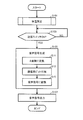
- FIG. 10 is a flowchart showing an operation flow in the electronic thermometer 1 for transmitting the measurement value to the receiving device 3.
- the CPU included in the control unit 12 reads out and executes a program stored in a ROM or the like included in the memory unit 13, and exhibits each function shown in FIG. It is realized by.
- step S101 an operation for measuring the temperature (body temperature) of the measurement site of the measurement subject is performed in step S101.
- This operation is the same as that of a normal electronic thermometer.
- the measured value is stored in a predetermined area of the memory unit 13.
- step S105 the CPU executes a process for generating an audio signal based on the measurement value.
- step S11 the CPU converts the measurement value obtained in decimal number into binary number.
- the measured value (36.8) may be multiplied by 10 and then binary (368 ⁇ 0101110000).
- step S13 the CPU uses a binary value as a data bit, and adds a start bit, a header code, and a stop bit, which are negotiated with the receiving device 3 in advance, before and after the data bit. Further, in step S13, the CPU determines whether the parity bit is 0 or 1 according to the oddity set for “1” in the transmission data, and adds it after the data bit (in the flowchart of FIG. 10, these data are communicated). Is expressed as a bit).
- step S ⁇ b> 15 the CPU assigns voices “ON” and “OFF” to binary values “0” and “1” in accordance with a relationship previously determined with the receiving device 3. Then, voices “ON” and “OFF” assigned to binary values “0” and “1” are converted into voice signals arranged at equal intervals.
- step S107 the CPU outputs the sound from the speaker 103 at a frequency determined in advance with the receiving device 3 in accordance with the generated sound signal.
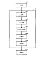
- FIG. 11 is a flowchart showing an operation flow in the receiving device 3 for receiving a measurement value from the electronic thermometer 1.
- the operation shown in the flowchart of FIG. 11 is realized by causing the CPU 30 to read and execute a program stored in the memory 34 to exhibit each function shown in FIG.
- step S201 when CPU 30 receives a voice input from microphone 33 (YES in step S201), a voice representing a measurement value from electronic thermometer 1 is input from the input voice signal using a frequency filter in step S203. Extract the frequency band of the signal.
- step S205 a pulse signal is generated from the extracted audio signal, for example, the audio ON timing is “ON”.
- step S207 the CPU 30 executes a process for specifying a measurement value from the generated pulse signal.
- step S21 the CPU 30 converts the pulse signal into a binary number according to a method corresponding to the conversion method in the electronic thermometer 1.
- the pulse signal is arranged according to the output speed of the stored audio signal, the pulse signal “ON” is set to “1”, and the output timing without the pulse signal “ON” is set to the pulse signal “ By assigning “0” as “OFF”, the pulse signal is converted to a binary numerical value.
- step S23 the CPU 30 removes the start bit, the header code, the parity bit, and the stop bit that have been negotiated with the electronic thermometer 1 in advance from the binary numerical value obtained in step S21, thereby obtaining the measurement value. Extract the corresponding data bits.
- step S25 the CPU 30 converts the binary data bit into a decimal number, and in step S27 specifies the measurement value.
- step S209 the CPU 30 causes the communication unit 35 to transmit the specified measurement value to the processing device 2.
- the measured value in the electronic thermometer 1 is transmitted to the receiving device 3 as an audio signal.
- the number of digits when converted to a binary number can be set in advance.
- other measurement values such as blood pressure values and blood oxygen concentrations, which will be described later. Therefore, it becomes possible to negotiate the form of the measurement data in advance between the electronic thermometer 1 on the transmission side and the reception device 3, and therefore, the measurement value can be reproduced from the audio signal on the reception device 3 side. That is, accurate measurement values can be transferred using audio signals.
- an electronic thermometer is often provided with a speaker for informing the start and end of measurement, a measured value, and the like. Therefore, the electronic thermometer 1 can transmit measurement values without adding a special communication function for transmitting measurement values such as a wireless communication function to the receiving device 3 to the configuration of a normal electronic thermometer. It can be. Therefore, it is possible to provide a communication function with a low price and a small size.
- the measurement value can be transmitted to the receiving device 3 with high accuracy.
- the user simply performs a simple operation of inserting the measured electronic thermometer 1 into the receiving device 3, and the measured value is automatically transmitted to the receiving device 3. Therefore, the measured value can be transferred much more accurately than when the user visually confirms the measured value and copies it on a medical record or the like.
- the electronic thermometer 1 transmits information specifying itself together with the measurement value to the receiving device 3.
- Information for specifying the electronic thermometer 1 is registered in advance in the receiving device 3. For example, immediately after the start bit, the information is specified in the receiving device 3 and inserted in the receiving device 3. It may be transmitted to.
- the frequency is set for each electronic thermometer 1 in advance, and the measured value is output to the receiving device 3 at the corresponding frequency, so that the receiving device 3 specifies the frequency and the electronic thermometer 1 is set. It may be specified.
- the measured value (body temperature) measured by the electronic thermometer 1 is transmitted to the receiving device 3 as an audio signal.
- a blood pressure measuring device or blood oxygen concentration measuring device is shown.
- the measurement value may be transmitted to the receiving device 3 as an audio signal by setting the device to the receiving device 3.
- the measured value is output as an audio signal when the second switch 102B of the electronic thermometer 1 is pressed.
- the output trigger is not limited to pressing the second switch 102B.
- a sound signal may be automatically output after a specified time has elapsed.
- the electronic thermometer 1 may be stored in the storage unit 32 of the receiving device 3 within the above time.
- it is not limited to a physical switch, and by detecting that the predetermined position of the electronic thermometer 1 has contacted the predetermined position of the storage part 32 electrically or magnetically, the measured value from the electronic thermometer 1 becomes an audio signal. It may be output.
Landscapes
- Engineering & Computer Science (AREA)
- Computer Networks & Wireless Communication (AREA)
- Physics & Mathematics (AREA)
- General Physics & Mathematics (AREA)
- Arrangements For Transmission Of Measured Signals (AREA)
- Measuring And Recording Apparatus For Diagnosis (AREA)
Abstract
被験者の測定部位の温度を測定し、測定値を出力する電子体温計(1)は、温度センサ(6)と、スピーカ(103)と、温度センサおよび前記発音装置に接続された制御部(12)とを備える。制御部は、発音装置を用いて測定値を出力させる制御として、温度センサからのセンサ信号に基づいて測定部位の温度を測定値として算出する処理と、測定値を音声信号に変換する処理と、発音装置から音声信号を出力させるための処理とを実行する。
Description
この発明は電子体温計、受信装置、および測定値の転送方法に関し、特に、音を利用して測定値を通信する機能を有した電子体温計、受信装置、および測定値の転送方法に関する。
医療施設における患者管理の一つとして、患者の体温管理がある。これは各患者の基礎的生体情報である体温を周期的に測定し、カルテにグラフとして記載することによりトレンドを観察し、代謝状態を把握するものである。
医療施設における体温管理では、看護師または患者自身が体温を体温計を用いて測定し、目視で確認した測定値を手動でカルテへ記載することが一般的に行なわれている。
しかしながら、このような方法では目視時の誤認識あるいは記載ミス(入力ミス)等の人的要因により、正しい測定値がカルテに記録されないリスクが避けられないという問題があった。
この問題に対して、たとえば特許文献1(特開2000-283855号公報)は、体温計に測定値に応じて点滅する表示装置を設け、該表示装置に測定値を表示させて受光素子で読み取らせる技術を開示している。
しかしながら、特許文献1(特開2000-283855号公報)の技術によると、体温計に測定値に応じて点滅させるための機能を搭載する必要があるために体温計が大型化したり、価格が高価になる。
また、読取装置を用いて表示装置に表示させた測定値を読み取らせるための操作が必要となるため、使用者の手間が増えて煩雑になる。
本発明の目的は、装置自体が大型化、高価となることを抑えつつ、かつ使用者の操作を煩雑化することなく、精度よい測定値の通信を可能とする電子体温計、受信装置、および測定値の転送方法を提供することである。
本発明のある局面に従うと、電子体温計は被験者の測定部位の温度を測定し、測定値を出力する電子体温計であって、温度センサと、発音装置と、温度センサおよび発音装置に接続された制御装置とを備える。制御装置は、発音装置を用いて測定値を出力させる制御として、温度センサからのセンサ信号に基づいて測定部位の温度を測定値として算出する処理と、測定値を音声信号に変換する処理と、発音装置から音声信号を出力させるための処理とを実行する。
好ましくは、電子体温計は測定値の出力を指示するための指示部をさらに備え、制御装置は指示部にも接続されて、指示部での指示に応じて上記制御を実行する。
好ましくは、測定値を音声信号に変換する処理は、測定値を2進数の値に変換するステップと、2進数の値のそれぞれに音声ON/OFFを割り当てることで音声信号を生成するステップとを含み、音声信号を出力させるための処理では、予め規定された出力速度で発音装置から音声信号を出力させる。
本発明の他の局面に従うと、受信装置は電子体温計から測定値を受信するための受信装置であって、電子体温計は、測定値を音声信号に変換して音声信号を出力し、受信装置は、マイクと、マイクに接続された制御装置とを備える。制御装置は、電子体温計での測定値から音声信号の変換する方法に対応した変換方法で、マイクで入力した音声信号を測定値に変換する処理と、測定値を出力する処理とを実行する。
好ましくは、電子体温計では、測定値を2進数の値に変換して得られる2進数の値のそれぞれに音声ON/OFFを割り当てることで音声信号を生成して、予め規定された出力速度で音声信号を出力し、音声信号を測定値に変換する処理は、音声信号に基づいてパルス信号を発生させるステップと、パルス信号と予め規定された出力速度とで得られるパルス信号の間隔に基づいてパルス信号を2進数の値に変換するステップと、2進数の値を10進数の値に変換することで測定値を特定するステップとを含む。
好ましくは、制御装置は、マイクで入力した音声信号から電子体温計で出力される音声信号の周波数帯を抽出することで、電子体温計から出力された音声信号を抽出する処理をさらに実行する。
好ましくは、受信装置は、電子体温計を収納するための収納部と、電子体温計が収納部に収納された状態となったときに、電子体温計に対して測定値の出力を指示するための指示部とをさらに備える。
より好ましくは、電子体温計は測定値の出力を指示するためのボタンを有し、指示部は、収納部内部の、電子体温計が収納部に収納された状態でボタンに接触する位置に設けられた突起である。
好ましくは、電子体温計は音声信号を出力するためのスピーカを有し、マイクは、電子体温計が収納部に収納された状態となったときに、スピーカ近傍に設けられる。
本発明のさらに他の局面に従うと、測定値の転送方法は、被験者の測定部位の温度を測定して測定値を出力する電子体温計と、電子体温計から測定値を受信するための受信装置とを含むシステムにおける測定値の転送方法であって、電子体温計で測定部位の温度を測定値として算出するステップと、電子体温計で測定値を音声信号に変換し、電子体温計に含まれる発音装置から音声信号を出力するステップと、受信装置に含まれるマイクで音声信号を入力するステップと、マイクで入力した音声信号を、受信装置で電子体温計での測定値から音声信号の変換する方法に対応した変換方法で測定値に変換するステップと、変換するステップで得られた測定値を受信装置から出力するステップとを備える。
この発明によると、電子体温計を大型化、高価とすることなく、かつ使用者の操作を煩雑化することなく、精度よく測定値を電子体温計から受信装置に対して送信することが可能となる。
以下に、図面を参照しつつ、本発明の実施の形態について説明する。以下の説明では、同一の部品および構成要素には同一の符号を付してある。それらの名称および機能も同じである。
<システム構成>
図1は、本実施の形態にかかる体温管理システムの構成の具体例を示す図である。
図1は、本実施の形態にかかる体温管理システムの構成の具体例を示す図である。
図1を参照して、体温管理システムは、被測定者の体温を測定するための電子体温計1と、電子体温計1から送信された当該電子体温計1での測定値を受信するための受信装置3と、電子カルテなどの管理用ソフトウェアを搭載し、受信装置3から送信された測定値を受信して当該測定値を管理用ソフトウェアで管理される図示しないメモリに書き込むための処理装置2とを含む。
受信装置3は電子体温計1を挿入してセットするための収納部32(図4)を有し、挿入口31から電子体温計1を挿入することで収納部32に電子体温計1がセットされる。当該挿入口31から受信装置3内の収納部32に電子体温計1をセットすることで、電子体温計1での測定値が受信装置3に転送される。
受信装置3と処理装置2とは、インターネットやLAN(Local Area Network)などのネットワーク7で電気的に接続されている。受信装置3から処理装置2への測定値の送信は、ネットワーク7を介さずに無線通信などを用いて直接になされてもよい。
<装置構成>
図2は、電子体温計1の概略構成を示す図である。図2の(A)は、電子体温計1の正面図であり、図2の(B)は図2の(A)のAA断面図であり、図2の(C)は図2の(B)のBB断面図である。
図2は、電子体温計1の概略構成を示す図である。図2の(A)は、電子体温計1の正面図であり、図2の(B)は図2の(A)のAA断面図であり、図2の(C)は図2の(B)のBB断面図である。
図2の(A)を参照して、本実施の形態にかかる電子体温計1は、内部が中空構造のハウジング100を備える。ハウジング100は、表示部101や情報出力部であるスピーカ103やスイッチ102A,102Bなどが設けられた略直方体の本体部110と、使用者の腋下や舌下、直腸などの測定部位に挟みこまれるなどして接触するプローブ部120とを含む。プローブ部120の先端には、使用者の測定部位の温度を測定するための測温部300が設けられる。図2の(B)および図2の(C)を参照して、ハウジング100の内部には、回路基板、電源、などで構成される内部部品4が収容される。
プローブ部120は、略直方体の本体部110の一方の端部から延びて本体部110に対して測温部300を支持する、内部が中空構造の先細りの棒状部材である。以降の説明において、プローブ部120の延びる軸方向を「長手方向」とも称する。
図2の(A)を参照して、本体部110の長手方向に平行する面には表示部101およびスピーカ103が設けられる。表示部101およびスピーカ103は必ずしも同じ面に設けられなくてもよい。以降の説明において、本体部110の少なくとも表示部101が設けられた面を、「正面」と称する。
図2の(B)および図2の(C)を参照して、プローブ部120の先端の測温部300は、ステンレス材(SUS:Steel Use Stainless)等からなるキャップ5と、キャップ5の内部に埋設固定されるサーミスタ等の温度センサ6とを含む。温度センサ6は、ハウジング100内に収容される内部部品4からプローブ部120の中空内部を通って延びるリード線41によって、内部部品4のCR発振回路(コンデンサと抵抗器を用いた発振回路)に電気的に接続される。温度センサ6は、測温部300の外表面から伝達される熱に応じて抵抗値を変化させ、この抵抗値の変化がCR発振回路に出力される。
なお、図2ではキャップ5を用いることでプローブ部120と測温部300とが別体として形成される例が示されている。しかしながら、キャップ5を用いず、樹脂成型された本体部110およびプローブ部120と一体成型されてもよい。この場合、本体部110とプローブ部120と測温部300とでハウジング100を構成する。
本体部110には、測定の開始および終了を指示するためのON/OFFスイッチである第1のスイッチ102Aと、受信装置3に対する測定値の通信の開始を指示するためのスイッチである第2のスイッチ102Bとが設けられる。図2では、一例として、第1のスイッチ102Aがプローブ部120および測温部300が設けられる側と反対側の端部に設けられ、第2のスイッチ102Bが第1のスイッチ102Aの設けられた端部、正面、および正面と平行の面のいずれの面とも異なる面、すなわち側面に設けられる例が示されている。しかしながら、これらスイッチの位置関係は図2に示される位置関係に限定されない。他の例として、第2のスイッチ102Bが本体部110の正面に設けられてもよい。また、他の例として、第1のスイッチ102Aが本体部110の側面に設けられてもよい。なお、後述する受信装置3の構成を容易にするため、好ましくは、第1のスイッチ102Aと第2のスイッチ102Bとは、同一面に設けられないように構成される。
図3は、本体部110をプローブ部120および測温部300が設けられる側と反対側の端部から見た図、すなわち第1のスイッチ102Aが設けられた側の端部から見た図である。図3を参照して、本体部110の断面形状は、正面を略平面とし、正面と反対の面が円弧状となった形状を有する。
なお、図3に表わされた形状は一例であって、好ましくは、正面とその反対側とが、または両側面が、異なる形状であれば他の形状であってもよい。
図4は、受信装置3の内部構成の概略を示す図である。図4を参照して、筐体表面に設けられた挿入口31から筐体内部に向かう方向に設けられた収納部32を有する。
挿入口31の断面は、図3に表わされた電子体温計1の本体部110の断面形状と類似形状であって、円弧状側の面に電子体温計1の表面を向けては挿入できないサイズとする。これによって、電子体温計1をその軸方向に挿入口31から筐体内部に向かう方向に挿入する際に、挿入口31の断面に対応した向きに挿入することになる。
収納部32は、挿入口31から筐体内部に向かう方向を長手方向とし、内部が中空構造の先細りの棒状形状である。その先細りの形状は電子体温計1のプローブ部120の形状と一致している。これによって、電子体温計1をその軸方向に挿入口31から筐体内部に向かう方向に挿入する際に、収納部32の、プローブ部120の形状と先細りの形状が一致する位置でプローブ部120が係持されることになり、電子体温計1の受信装置3に対する長手方向の位置が一定に保持される。
収納部32の内壁には突起32Aが設けられる。突起32Aは、挿入口31の断面に応じた向きに電子体温計1を収納部32に挿入し、プローブ部120の形状と先細りの形状が一致する位置でプローブ部120が係持された状態で、電子体温計1の第2のスイッチ102Bと接触して第2のスイッチ102Bを押下する位置に設けられる。なお、突起32Aは、第2のスイッチ102Bの位置、操作方法に応じた形態で設けられる。すなわち、図4に示されたような単純な突起形状に限定されず、第2のスイッチ102Bがスライド式である場合には当該スライドを行ない得る形状とし、第2のスイッチ102Bが凹形状であって当該凹部を押下するものである場合には当該凹部に合致するような凸形状とする。
このように構成されることで、ユーザが第2のスイッチ102Bを押下するといった特別の操作を行なうことなく、電子体温計1を受信装置3の収納部32に挿入するのみで第2のスイッチ102Bが自動的に押下されることになる。また、挿入口31の断面および収納部32の形状が上述の形状であることによって受信装置3に電子体温計1をセットしたときの電子体温計1の受信装置3における状態を、第2のスイッチ102Bが突起32Aによって押下されるような状態とすることができる。
さらに図4を参照して、受信装置3はその内部に、マイク33と、当該マイク33と電気的に接続されて全体制御を行なうためのCPU(Central Processing Unit)30と、CPU30で実行されるプログラムを格納するためのメモリ34と、CPU30での処理の結果得られた測定値をネットワーク7を介して処理装置2に対して出力するための通信部35とを含む。
CPU30は、マイク33から入力された音声信号を解析して測定値を取得するための演算を行なう。
マイク33は、好ましくは、挿入口31の断面に応じた向きに電子体温計1を収納部32に挿入し、プローブ部120の形状と先細りの形状が一致する位置でプローブ部120が係持された状態における電子体温計1に設けられたスピーカ103の近傍となる位置に設けられる。このように配置することで、電子体温計1のスピーカ103から大きな音で出力しなくてもマイク33で集音されることになる。さらに、収納部32に収納された状態でスピーカ103から発せられた音声がマイク33で集音されることになるので、ノイズの影響による通信品質の劣化を防止することができる。
<機能ブロック>
図5は、電子体温計1の機能ブロック図である。
図5は、電子体温計1の機能ブロック図である。
図5を参照して、電子体温計1は、機能ブロックとして、制御部12と、メモリ部13と、表示部101と、スイッチ102A,102Bと、スピーカ103と、電源部17と、温度センサ6とを含む。制御部12は、たとえば内部部品4の回路基板に搭載されるCPUにて構成され、電子体温計1の全体を制御する。メモリ部13は、たとえば内部部品4に含まれるROM(Read-Only Memory)やRAM(Random-Access Memory)にて構成され、体温測定のための処理手順を制御部12等に実行させるためのプログラムを記憶したり、測定結果等を記憶したりするために用いられる。
表示部101は、たとえばLCD(Liquid Crystal Display)等の表示パネルにて構成され、測定結果等を表示するために用いられる。スイッチ102A,102Bは、たとえば押し釦にて構成され、押下されることで操作信号を制御部12や電源部17に入力する。スピーカ103は、後述する、受信装置3との通信用の音を発するために用いられる。また、スピーカ103は、測定中や測定が終了した、などの測定状態、使用者の操作を受け付けたこと、等を使用者に知らせるためにも用いられる。
電源部17は、たとえば内部部品4に含まれるボタン電池によって構成され、制御部12に電源としての電力を供給するために用いられる。制御部12にて測定動作のためのプログラムを実行していない状態においては、電源部17は制御部12に対して該プログラム実行時よりも少ない微小電力を供給している。この状態を、以降、スタンバイ状態と称する。電源部17はスタンバイ状態において操作信号を受け付けると、制御部12にて測定動作のためのプログラムを実行するために必要な電力を制御部12に対して供給する。
温度センサ6は、腋下や舌下、直腸等の測定部位に挟み込まれたり挿し込まれたりすることで温度を検出し、検出結果を制御部12に入力する。
<動作概要>
本実施の形態にかかる体温管理システムでの動作について説明する。
本実施の形態にかかる体温管理システムでの動作について説明する。
まず、電子体温計1を用いて被測定者の体温を測定する。測定値は電子体温計1のメモリ部13に記憶される。
電子体温計1での測定値を処理装置2の電子カルテなどに書き込む際、ユーザは、電子体温計1を受信装置3の挿入口31から挿入して受信装置3にセットする。これによって、電子体温計1から受信装置3に対して測定値が送信され、受信装置3がその測定値を受信する。受信された測定値は受信装置3からネットワーク7を介して処理装置2に送られ、電子カルテなどに書き込まれる。
本実施の形態にかかる体温管理システムでは、電子体温計1から受信装置3に測定値を転送する際に音を利用した通信が用いられる。具体的に、電子体温計1は測定値を2進数に変換し、音の鳴動(ON/OFF)を2進数の0と1とに割り当てて、測定値を2進数で表わした数値を音の鳴動に変換して得られる音声信号を規定の速度で出力する。受信装置3はその音を集音して上記規定の出力速度と鳴動の間隔とに基づいて2進数で表わされた数値を得、その数値を10進数に変換することで測定値を取得する。
<制御ブロック>
図6は、受信装置3に測定値を送信するための電子体温計1の制御ブロック図である。
図6は、受信装置3に測定値を送信するための電子体温計1の制御ブロック図である。
図6を参照して、電子体温計1は、測定値として温度センサ6からのセンサ信号の入力を受け付けるための温度入力部121と、上記センサ信号に基づいて測定部位の温度を10進数の測定値として算出するための算出部122と、第2のスイッチ102Bからの当該第2のスイッチ102Bが押下されたことによる操作信号の入力を受け付けるための操作入力部123と、予め変換式を記憶しておき、上記操作信号の入力にしたがって算出された10進数の測定値を2進数に変換し、その数値を音の鳴動(ON/OFF)に変換することで音声信号を特定するための変換部124と、スピーカ103から予め規定された速度で上記音声信号を出力させる処理を行なうための出力部125とを含む。
これらは、制御部12に含まれるCPUがメモリ部13に含まれるROM等に記憶されるプログラムを読み出して実行することによって主にCPU上に形成される機能であってもよいし、一部がハードウェアによって実現される機能であってもよい。
図7は、電子体温計1から出力される音声信号を説明するための図である。例として、10進数で36.8℃の測定値が得られた場合を説明する。
図7を参照して、変換部124は得られた測定値36.8℃を10倍した「368」を2進数で10桁の値「0101110000」に変換して、データビットとする。そして、データビットの先頭と末尾とに、それぞれ、予め設定したスタートビットおよびヘッダコードと、ストップビットとを付加する。さらに、変換部124は、送信データ中の「1」について設定された奇偶に応じてパリティビットとして0か1かを決定し、データビットの後に付加する。
スタートビットとしてたとえば予め1が設定されているときには、変換部124は先頭に1を付加する。ヘッダコードとしてたとえば「011」が予め設定されているときには、変換部124はスタートビットの後に「011」を付加する。ストップビットとしてたとえば予め0が設定されているときには、変換部124は末尾に0を付加する。さらに、送信データ中の「1」の数が偶数と設定されている場合に、変換部124は、以上のデータ中に「1」が7つ含まれることになるためにパリティビットとして「1」を決定し、データビットの後に「1」を付加する。
以上のようにして、測定値36.8℃は、図7の(A)に表わされた2進数の送信データ「1011010111000010」に変換される。
さらに、変換部124は、予め2進数の送信データの「0」および「1」と鳴動(ON/OFF)との対応を記憶している。一例として、2進数の送信データの「1」に音声ONが対応し、2進数の送信データの「0」に音声OFFが対応しているものとする。
変換部124は、記憶している対応関係に基づいて、2進数の送信データの「0」「1」に音声のON/OFFを割り当てることで、音声信号に変換する。対応関係が上の例である場合、図7の(A)に表わされた2進数の送信データ「1011010111000010」は、図7の(B)に表わされた、音声が「ON/OFF/ON/ON/OFF/ON/OFF/ON/ON/ON/OFF/OFF/OFF/OFF/ON/OFF」である音声信号に変換される。なお、図7の(B)において、音声信号における音声「ON」のタイミングは3本の縦線が並んだマークで表わされ、音声「OFF」のタイミングは当該マークがない部分で表わされている。
出力部125は、変換部124で得られた音声信号を、受信装置3との間で予め規定された周波数で、受信装置3との間で予め規定された速度で出力させる。図7の(C)は、出力部125に記憶されている音声信号の出力速度を表わしている。図7の(C)に示されるように、出力部125は、規定された等間隔のタイミングt1~t16のそれぞれに変換された音声信号の音声「ON」または音声「OFF」のタイミングを順に割り当てて、上記出力速度に従って音声信号を出力させる。2進数の送信データが図7の(B)に表わされた信号である場合、出力部125は、タイミングt1、t3、t4、t6、t8、t9、t10、t15に音声ONとし、他のタイミングに音声OFFとなるように出力させる。つまり、変換部124は、図7の(B)に「ON」で表わされた時間間隔で所定の周波数の音声を出力するような音声信号を生成することになる。
図8は、電子体温計1から測定値を受信するための受信装置3の制御ブロック図である。
図8を参照して、受信装置3は、マイク33からの音声信号の入力を受け付けるための入力部301と、電子体温計1からの音声信号に対応した周波数帯の音声信号を抽出するための周波数フィルタを含んで、入力された音声信号から電子体温計1からの音声信号に対応した周波数帯の音声信号を抽出するためのフィルタ部302と、抽出された音声信号をパルス信号に変換するためのパルス発生部303と、予めパルス信号の発生間隔を記憶しておき、当該発生間隔とパルス信号とに基づいてパルス信号を2進数で表わされた値に変換し、その数値を10進数の値に変換することで、電子体温計1から送信された測定値を得るための変換部304と、得られた測定値を通信部35で処理装置2に対して送信させる処理を行なうための出力部305とを含む。
これらは、CPU30がメモリ34に記憶されるプログラムを読み出して実行することによって主にCPU30上に形成される機能であってもよいし、一部がハードウェアによって実現される機能であってもよい。たとえば、パルス発生部303はパルス発生回路によって構成されてもよい。
図9は、受信装置3での音声信号の処理を説明するための図である。例として、図7で表わされた音声信号を受信した場合を説明する。
図9を参照して、パルス発生部303は、電子体温計1からの音声信号に対応した周波数帯の音声信号の入力があったタイミングをONとするパルス信号を発生させる。図7の(B)に表わされた音声信号が図7の(C)に表わされたタイミング、つまり、タイミングt1~t16でそれぞれ、音声が「ON/OFF/ON/ON/OFF/ON/OFF/ON/ON/ON/OFF/OFF/OFF/OFF/ON/OFF」である音声信号が電子体温計1から出力された場合、パルス発生部303は、図9の(A)に表わされるパルス信号を発生させる。
変換部304は、予め、電子体温計1の出力部125が記憶している音声信号の出力速度を記憶している。つまり、出力部125が記憶している等間隔のタイミングt1~t16と同じ等間隔のタイミングt1~t16(図9の(B))を記憶している。そして、変換部304は、パルス信号にタイミングt1~t16を当てはめて、そのパルス信号の時間間隔に基づいてパルス信号を2進数の値に変換する。
図9の(A)のパルス信号が発生し、図9の(B)のタイミングt1~t16が記憶されている場合、変換部304は、タイミングt1~t16でそれぞれ、「ON/OFF/ON/ON/OFF/ON/OFF/ON/ON/ON/OFF/OFF/OFF/OFF/ON/OFF」のパルス信号と解析する。そして、パルス信号「ON」に「1」、パルス信号「OFF」に「0」を割り当てることでこのパルス信号を、図9の(C)に表わされる、2進数の値「1011010111000010」に変換する。つまり、電子体温計1で発する音声の時間間隔に基づいて、その音声信号を2進数の値に変換する。
なお、パルス信号「ON」「OFF」に「1」「0」のいずれを割り当てるかについては、予め電子体温計1における変換方法に対応して規定されており、当該規定に従って電子体温計1の変換部124は測定値が変換された2進数の値を音声データに変換し、受信装置3の変換部304はパルス信号を2進数の値に変換する。
さらに、電子体温計1と受信装置3との間では予め、スタートビット、ヘッダコード、パリティビット、およびストップビットを付加すること、およびその内容が取り決められており、その取り決めに従って電子体温計1の変換部124は上述のようにデータビットにそれらを付加し、受信装置3の変換部304は得られた2進数の値からこれらを取り除いてデータビットを取り出す。
スタートビット、ヘッダコード、パリティビット、およびストップビットが図7の(A)に表わされたものである場合、受信装置3の変換部304は、図9の(C)に表わされたように、パルス信号から得られた2進数の値「1011010111000010」の先頭からスタートビットとして「1」、およびヘッダコードとして「011」を除き、末尾からストップビットとして「0」を除く。さらに、ストップビットとして「0」の直前の「1」をパリティビットとして除く。これにより、変換部304は、測定値を2進数で表した値として「0101110000」を得る。
変換部304は、さらに、得られた2進数の値を10進数に変換することで、測定値を得る。図9の(C)に表わされたように、2進数の値「0101110000」が得られると、変換部304はこの値を10進数に変換して「368」を得、電子体温計1との間での取り決めに従って368を10で除して、測定値36.8℃を得る。
<動作フロー>
図10は、受信装置3に測定値を送信するための、電子体温計1での動作の流れを表わしたフローチャートである。図10のフローチャートに表わされた動作は、制御部12に含まれるCPUがメモリ部13に含まれるROM等に記憶されるプログラムを読み出して実行し、図6に示される各機能を発揮させることによって実現される。
図10は、受信装置3に測定値を送信するための、電子体温計1での動作の流れを表わしたフローチャートである。図10のフローチャートに表わされた動作は、制御部12に含まれるCPUがメモリ部13に含まれるROM等に記憶されるプログラムを読み出して実行し、図6に示される各機能を発揮させることによって実現される。
図10を参照して、ステップS101で被測定者の測定部位の温度(体温)を測定するための動作が行なわれる。この動作は、通常の電子体温計の動作と同様である。測定値はメモリ部13の所定領域に記憶される。
この後、電子体温計1が受信装置3の挿入口31から収納部32に収納されると、収納部32内部の突起32Aが第2のスイッチ102Bと接触する(図10のフローチャートでは第2のスイッチ102Bが送信スイッチと表現されている)。このようにして第2のスイッチ102Bが押下されたことが検知されると(ステップS103でYES)、ステップS105でCPUは、測定値に基づいて音声信号を生成するための処理を実行する。
詳しくは、ステップS11でCPUは、10進数で得られている測定値を2進数に変換する。ここでは、上述のように、測定値(36.8)を10倍してから2進数(368→0101110000)してもよい。ステップS13でCPUは、2進数の値をデータビットとし、その前後に、予め受信装置3との間で取り決められているスタートビットおよびヘッダコードと、ストップビットとを付加する。さらに、ステップS13でCPUは、送信データ中の「1」について設定された奇遇に応じてパリティビットとして0か1かを決定し、データビットの後に付加する(図10のフローチャートではこれらデータが通信用ビットと表現されている)。そして、ステップS15でCPUは、予め受信装置3との間で取り決められている関係に従って2進数の値「0」「1」に音声「ON」「OFF」を割り当てる。そして、2進数の値「0」「1」に割り当てられた音声「ON」「OFF」が等間隔で配置された音声信号に変換する。
ステップS107でCPUは、生成された音声信号に従って音声を予め受信装置3との間で取り決められた周波数でスピーカ103から出力させる。
図11は、電子体温計1から測定値を受信するための、受信装置3での動作の流れを表わしたフローチャートである。図11のフローチャートに表わされた動作は、CPU30がメモリ34に記憶されるプログラムを読み出して実行し、図8に示される各機能を発揮させることによって実現される。
図11を参照して、CPU30はマイク33から音声入力を受け付けると(ステップS201でYES)、ステップS203で周波数フィルタを用いて、入力された音声信号から、電子体温計1からの測定値を表わす音声信号の周波数帯を抽出する。ステップS205で、抽出された音声信号からたとえば音声ONのタイミングを「ON」とするパルス信号を発生させる。そして、ステップS207でCPU30は、発生させたパルス信号から測定値を特定するための処理を実行する。
詳しくは、ステップS21でCPU30は、電子体温計1での変換方法に応じた方法に従って、パルス信号を2進数の数値に変換する。ここでは、上述のように、記憶されている音声信号の出力速度に沿ってパルス信号を配置し、パルス信号「ON」に「1」、パルス信号「ON」のない出力のタイミングをパルス信号「OFF」として「0」を割り当てることで、パルス信号を2進数の数値に変換する。
ステップS23でCPU30は、ステップS21で得られた2進数の数値から、予め電子体温計1との間で取り決められているスタートビット、ヘッダコード、パリティビット、およびストップビットを取り除くことで、測定値に対応したデータビットを抽出する。
ステップS25でCPU30は2進数の数値であるデータビットを10進数に変換し、ステップS27でその値から測定値を特定する。
ステップS209でCPU30は、特定された測定値を通信部35から処理装置2に対して送信させる。
<実施の形態の効果>
以上の動作が電子体温計1および受信装置3で行なわれることで、電子体温計1における測定値が、音声信号として受信装置3に対して送信されることになる。特に、体温などヒトの身体から測定し得る値は範囲が限定されているものであるため、2進数に変換されたときの桁数を予め設定可能である。これは、後述する、血圧値や血中酸素濃度などの他の測定値でも同様である。そのため、送信側の電子体温計1と受信装置3との間で予め測定データの形態を取り決めることが可能となり、それ故、受信装置3側で音声信号から測定値を再現することができる。すなわち、音声信号を利用して正確な測定値の転送が可能となる。
以上の動作が電子体温計1および受信装置3で行なわれることで、電子体温計1における測定値が、音声信号として受信装置3に対して送信されることになる。特に、体温などヒトの身体から測定し得る値は範囲が限定されているものであるため、2進数に変換されたときの桁数を予め設定可能である。これは、後述する、血圧値や血中酸素濃度などの他の測定値でも同様である。そのため、送信側の電子体温計1と受信装置3との間で予め測定データの形態を取り決めることが可能となり、それ故、受信装置3側で音声信号から測定値を再現することができる。すなわち、音声信号を利用して正確な測定値の転送が可能となる。
通常、電子体温計には、測定の開始や終了、測定値などを報知するためのスピーカが設けられていることが多い。そのため、電子体温計1では、受信装置3に対して無線通信機能などの測定値を送信するための特別の通信機能を通常の電子体温計の構成に対して付加することなく、測定値の送信を可能とすることができる。それ故、低価格、小型で通信機能を持たせることが可能となる。
また、ノイズの影響による通信品質の劣化を防止することができる構成であるため、精度よく測定値を受信装置3に対して送信することができる。
このようにすることで、ユーザは、測定後の電子体温計1を受信装置3に対して挿入するという簡単な操作を行なうのみで、自動的に測定値が受信装置3に送信されて、処理装置2に転送することができるので、ユーザが目視で測定値を確認してカルテ等に書き写す場合と比較して格段に正確に測定値を転送することが可能となる。
<他の例>
なお、たとえば医療機関など、体温管理システムに複数の電子体温計1が含まれる場合が想定される。この場合、電子体温計1は、測定値と共に自身を特定する情報を受信装置3に対して送信する。電子体温計1を特定する情報は予め受信装置3に対して登録されており、たとえばスタートビットの直後、などの、予め受信装置3との間で取り決めた位置に挿入されることで受信装置3に対して送信されてもよい。他の例として、予め電子体温計1ごとに周波数が設定されており、対応した周波数で測定値を受信装置3に対して出力することで、受信装置3が周波数を特定することで電子体温計1を特定するようにしてもよい。
なお、たとえば医療機関など、体温管理システムに複数の電子体温計1が含まれる場合が想定される。この場合、電子体温計1は、測定値と共に自身を特定する情報を受信装置3に対して送信する。電子体温計1を特定する情報は予め受信装置3に対して登録されており、たとえばスタートビットの直後、などの、予め受信装置3との間で取り決めた位置に挿入されることで受信装置3に対して送信されてもよい。他の例として、予め電子体温計1ごとに周波数が設定されており、対応した周波数で測定値を受信装置3に対して出力することで、受信装置3が周波数を特定することで電子体温計1を特定するようにしてもよい。
さらに、以上の説明では、電子体温計1で測定された測定値(体温)を受信装置3に音声信号で送信する例が示されているが、同様にして血圧測定器や血中酸素濃度測定器などでも、当該装置を受信装置3にセットすることで、測定値を音声信号で受信装置3に対して送信するようにしてもよい。
また、以上の説明では、電子体温計1の第2のスイッチ102Bが押下されることで音声信号として測定値が出力されるものとしている。しかしながら、出力のトリガは第2のスイッチ102Bの押下に限定されるものではない。たとえば、測定後、指定された時間の経過後に自動的に音声信号として出力されるようにしてもよい。この場合、上記時間内に電子体温計1を受信装置3の収納部32に収納するようにすればよい。また、物理的なスイッチに限定されず、電気的や磁気的に電子体温計1の所定位置が収納部32の所定位置に接触したことを検知することで、電子体温計1から測定値が音声信号として出力されるようにしてもよい。
今回開示された実施の形態はすべての点で例示であって制限的なものではないと考えられるべきである。本発明の範囲は上記した説明ではなくて請求の範囲によって示され、請求の範囲と均等の意味および範囲内でのすべての変更が含まれることが意図される。
1 電子体温計、2 処理装置、3 受信装置、4 内部部品、5 キャップ、6 温度センサ、7 ネットワーク、12 制御部、13 メモリ部、17 電源部、30 CPU、31 挿入口、32 収納部、32A 突起、33 マイク、34 メモリ、35 通信部、41 リード線、100 ハウジング、101 表示部、102A 第1のスイッチ、102B 第2のスイッチ、103 スピーカ、110 本体部、120 プローブ部、121 温度入力部、122 算出部、123 操作入力部、124,304 変換部、125,305 出力部、300 測温部、301 入力部、302 フィルタ部、303 パルス発生部。
Claims (10)
- 被験者の測定部位の温度を測定し、測定値を出力する電子体温計(1)であって、
温度センサ(6)と、
発音装置(103)と、
前記温度センサおよび前記発音装置に接続された制御装置(12)とを備え、
前記制御装置は、前記発音装置を用いて前記測定値を出力させる制御として、
前記温度センサからのセンサ信号に基づいて前記測定部位の温度を前記測定値として算出する処理と、
前記測定値を音声信号に変換する処理と、
前記発音装置から前記音声信号を出力させるための処理とを実行する、電子体温計。 - 前記測定値の出力を指示するための指示部をさらに備え、
前記制御装置は前記指示部にも接続されて、前記指示部での指示に応じて前記制御を実行する、請求項1に記載の電子体温計。 - 前記測定値を前記音声信号に変換する処理は、
前記測定値を2進数の値に変換するステップと、
前記2進数の値のそれぞれに音声ON/OFFを割り当てることで音声信号を生成するステップとを含み、
前記音声信号を出力させるための処理では、予め規定された出力速度で前記発音装置から前記音声信号を出力させる、請求項1に記載の電子体温計。 - 電子体温計(1)から測定値を受信するための受信装置(3)であって、
前記電子体温計は、前記測定値を音声信号に変換して前記音声信号を出力し、
マイク(33)と、
前記マイクに接続された制御装置(30)とを備え、
前記制御装置は、
前記電子体温計での前記測定値から前記音声信号の変換する方法に対応した変換方法で、前記マイクで入力した前記音声信号を前記測定値に変換する処理と、
前記測定値を出力する処理とを実行する、受信装置。 - 前記電子体温計では、前記測定値を2進数の値に変換して得られる前記2進数の値のそれぞれに音声ON/OFFを割り当てることで音声信号を生成して、予め規定された出力速度で前記音声信号を出力し、
前記音声信号を前記測定値に変換する処理は、
前記音声信号に基づいてパルス信号を発生させるステップと、
前記パルス信号と前記予め規定された出力速度とで得られる前記パルス信号の間隔に基づいて前記パルス信号を2進数の値に変換するステップと、
前記2進数の値を10進数の値に変換することで前記測定値を特定するステップとを含む、請求項4に記載の受信装置。 - 前記制御装置は、前記マイクで入力した音声信号から前記電子体温計で出力される前記音声信号の周波数帯を抽出することで、前記電子体温計から出力された前記音声信号を抽出する処理をさらに実行する、請求項4に記載の受信装置。
- 前記電子体温計を収納するための収納部と、
前記電子体温計が前記収納部に収納された状態となったときに、前記電子体温計に対して前記測定値の出力を指示するための指示部とをさらに備える、請求項4に記載の受信装置。 - 前記電子体温計は前記測定値の出力を指示するためのボタンを有し、
前記指示部は、前記収納部内部の、前記電子体温計が前記収納部に収納された状態で前記ボタンに接触する位置に設けられた突起である、請求項7に記載の受信装置。 - 前記電子体温計は前記音声信号を出力するためのスピーカを有し、
前記マイクは、前記電子体温計が前記収納部に収納された状態となったときに、前記スピーカ近傍に設けられる、請求項7に記載の受信装置。 - 被験者の測定部位の温度を測定して測定値を出力する電子体温計(1)と、前記電子体温計から前記測定値を受信するための受信装置(3)とを含むシステムにおける測定値の転送方法であって、
前記電子体温計で前記測定部位の温度を前記測定値として算出するステップと、
前記電子体温計で前記測定値を音声信号に変換し、前記電子体温計に含まれる発音装置から前記音声信号を出力するステップと、
前記受信装置に含まれるマイクで前記音声信号を入力するステップと、
前記マイクで入力した前記音声信号を、前記受信装置で前記電子体温計での前記測定値から前記音声信号の変換する方法に対応した変換方法で前記測定値に変換するステップと、
前記変換するステップで得られた前記測定値を前記受信装置から出力するステップとを備える、測定値の転送方法。
Applications Claiming Priority (2)
| Application Number | Priority Date | Filing Date | Title |
|---|---|---|---|
| JP2011056141A JP2012193967A (ja) | 2011-03-15 | 2011-03-15 | 電子体温計、受信装置、および測定値の転送方法 |
| JP2011-056141 | 2011-03-15 |
Publications (1)
| Publication Number | Publication Date |
|---|---|
| WO2012124356A1 true WO2012124356A1 (ja) | 2012-09-20 |
Family
ID=46830437
Family Applications (1)
| Application Number | Title | Priority Date | Filing Date |
|---|---|---|---|
| PCT/JP2012/050178 Ceased WO2012124356A1 (ja) | 2011-03-15 | 2012-01-06 | 電子体温計、受信装置、および測定値の転送方法 |
Country Status (2)
| Country | Link |
|---|---|
| JP (1) | JP2012193967A (ja) |
| WO (1) | WO2012124356A1 (ja) |
Cited By (1)
| Publication number | Priority date | Publication date | Assignee | Title |
|---|---|---|---|---|
| JP7452817B2 (ja) | 2020-08-14 | 2024-03-19 | テルモ株式会社 | 電子体温計セット及び情報処理方法 |
Families Citing this family (1)
| Publication number | Priority date | Publication date | Assignee | Title |
|---|---|---|---|---|
| JP5814960B2 (ja) * | 2013-02-25 | 2015-11-17 | 株式会社東芝 | 電子体温計、受信装置及び電子体温計システム |
Citations (4)
| Publication number | Priority date | Publication date | Assignee | Title |
|---|---|---|---|---|
| JPH0415799U (ja) * | 1990-05-31 | 1992-02-07 | ||
| JP2000283855A (ja) * | 1999-03-30 | 2000-10-13 | Terumo Corp | 電子体温計及び体温データ読み取り装置 |
| JP2001313615A (ja) * | 2000-04-27 | 2001-11-09 | Seiko Epson Corp | 電子機器 |
| JP2011179900A (ja) * | 2010-02-26 | 2011-09-15 | Terumo Corp | 電子体温計 |
-
2011
- 2011-03-15 JP JP2011056141A patent/JP2012193967A/ja not_active Withdrawn
-
2012
- 2012-01-06 WO PCT/JP2012/050178 patent/WO2012124356A1/ja not_active Ceased
Patent Citations (4)
| Publication number | Priority date | Publication date | Assignee | Title |
|---|---|---|---|---|
| JPH0415799U (ja) * | 1990-05-31 | 1992-02-07 | ||
| JP2000283855A (ja) * | 1999-03-30 | 2000-10-13 | Terumo Corp | 電子体温計及び体温データ読み取り装置 |
| JP2001313615A (ja) * | 2000-04-27 | 2001-11-09 | Seiko Epson Corp | 電子機器 |
| JP2011179900A (ja) * | 2010-02-26 | 2011-09-15 | Terumo Corp | 電子体温計 |
Cited By (1)
| Publication number | Priority date | Publication date | Assignee | Title |
|---|---|---|---|---|
| JP7452817B2 (ja) | 2020-08-14 | 2024-03-19 | テルモ株式会社 | 電子体温計セット及び情報処理方法 |
Also Published As
| Publication number | Publication date |
|---|---|
| JP2012193967A (ja) | 2012-10-11 |
Similar Documents
| Publication | Publication Date | Title |
|---|---|---|
| JP5820396B2 (ja) | 血糖測定装置 | |
| JP5975228B2 (ja) | 交換可能なプローブを有する医療用ハンドヘルド測定器具 | |
| CN103519794A (zh) | 测量装置、测量方法、程序、存储介质和测量系统 | |
| CN105764414B (zh) | 用于测量生物信号的方法及装置 | |
| CN1979173A (zh) | 分析系统中信息片段的可听输出方法 | |
| JP2003288660A (ja) | 分析システムからデータ処理ユニットにデータを転送する、抜き差し可能なデータ転送モジュールを有するシステム | |
| JP2001017404A (ja) | 医療用測定装置 | |
| US12357264B2 (en) | Wheezing detection device and wheezing detection program | |
| US20140046199A1 (en) | Method for measuring human vital signs and portable terminal adopting the same | |
| JP5909120B2 (ja) | 情報処理システム及び装置及び情報処理装置の制御方法、並びに、コンピュータプログラム及びコンピュータ可読記憶媒体 | |
| WO2012124356A1 (ja) | 電子体温計、受信装置、および測定値の転送方法 | |
| JP2015153135A (ja) | 測定器 | |
| WO2011143823A1 (zh) | 一种可测量体温的血氧测量仪 | |
| JP5367619B2 (ja) | 電子体温計 | |
| CN100484464C (zh) | 居家保健交互式装置 | |
| CN101365376B (zh) | 用于采集生理测量数据的方法和装置 | |
| JP6951805B1 (ja) | 体温計 | |
| JP2007330328A (ja) | 体温計及び体温情報収集システム | |
| US20220280068A1 (en) | Spirometry system for mitigating physical user errors | |
| KR20150009029A (ko) | 이어폰 단자를 이용한 모바일 단말과 외부 전자기기 간의 전력 및 데이터 송수신 방법 및 모바일 단말과 전력 및 데이터를 송수신하는 기능을 갖는 전자기기 | |
| JP2012063304A (ja) | 電子体温計 | |
| JP2019187529A (ja) | 生体音測定装置、生体音測定装置の作動方法、生体音測定装置の作動プログラム | |
| JP2014052216A (ja) | 測定システム | |
| JP2022042442A (ja) | 呼吸音情報処理システム及び呼吸音測定装置 | |
| CN210603657U (zh) | 温度测量装置 |
Legal Events
| Date | Code | Title | Description |
|---|---|---|---|
| 121 | Ep: the epo has been informed by wipo that ep was designated in this application |
Ref document number: 12757621 Country of ref document: EP Kind code of ref document: A1 |
|
| NENP | Non-entry into the national phase |
Ref country code: DE |
|
| 122 | Ep: pct application non-entry in european phase |
Ref document number: 12757621 Country of ref document: EP Kind code of ref document: A1 |