WO2012124317A1 - ベクトル波記録媒体、及び多重記録再生方法 - Google Patents
ベクトル波記録媒体、及び多重記録再生方法 Download PDFInfo
- Publication number
- WO2012124317A1 WO2012124317A1 PCT/JP2012/001769 JP2012001769W WO2012124317A1 WO 2012124317 A1 WO2012124317 A1 WO 2012124317A1 JP 2012001769 W JP2012001769 W JP 2012001769W WO 2012124317 A1 WO2012124317 A1 WO 2012124317A1
- Authority
- WO
- WIPO (PCT)
- Prior art keywords
- recording
- vector wave
- recording medium
- light
- polarization
- Prior art date
- Legal status (The legal status is an assumption and is not a legal conclusion. Google has not performed a legal analysis and makes no representation as to the accuracy of the status listed.)
- Ceased
Links
Images





Classifications
-
- G—PHYSICS
- G03—PHOTOGRAPHY; CINEMATOGRAPHY; ANALOGOUS TECHNIQUES USING WAVES OTHER THAN OPTICAL WAVES; ELECTROGRAPHY; HOLOGRAPHY
- G03H—HOLOGRAPHIC PROCESSES OR APPARATUS
- G03H1/00—Holographic processes or apparatus using light, infrared or ultraviolet waves for obtaining holograms or for obtaining an image from them; Details peculiar thereto
- G03H1/26—Processes or apparatus specially adapted to produce multiple sub- holograms or to obtain images from them, e.g. multicolour technique
-
- G—PHYSICS
- G03—PHOTOGRAPHY; CINEMATOGRAPHY; ANALOGOUS TECHNIQUES USING WAVES OTHER THAN OPTICAL WAVES; ELECTROGRAPHY; HOLOGRAPHY
- G03H—HOLOGRAPHIC PROCESSES OR APPARATUS
- G03H1/00—Holographic processes or apparatus using light, infrared or ultraviolet waves for obtaining holograms or for obtaining an image from them; Details peculiar thereto
- G03H1/26—Processes or apparatus specially adapted to produce multiple sub- holograms or to obtain images from them, e.g. multicolour technique
- G03H1/2645—Multiplexing processes, e.g. aperture, shift, or wavefront multiplexing
-
- G—PHYSICS
- G11—INFORMATION STORAGE
- G11B—INFORMATION STORAGE BASED ON RELATIVE MOVEMENT BETWEEN RECORD CARRIER AND TRANSDUCER
- G11B7/00—Recording or reproducing by optical means, e.g. recording using a thermal beam of optical radiation by modifying optical properties or the physical structure, reproducing using an optical beam at lower power by sensing optical properties; Record carriers therefor
- G11B7/004—Recording, reproducing or erasing methods; Read, write or erase circuits therefor
- G11B7/0065—Recording, reproducing or erasing by using optical interference patterns, e.g. holograms
-
- G—PHYSICS
- G11—INFORMATION STORAGE
- G11B—INFORMATION STORAGE BASED ON RELATIVE MOVEMENT BETWEEN RECORD CARRIER AND TRANSDUCER
- G11B7/00—Recording or reproducing by optical means, e.g. recording using a thermal beam of optical radiation by modifying optical properties or the physical structure, reproducing using an optical beam at lower power by sensing optical properties; Record carriers therefor
- G11B7/24—Record carriers characterised by shape, structure or physical properties, or by the selection of the material
- G11B7/241—Record carriers characterised by shape, structure or physical properties, or by the selection of the material characterised by the selection of the material
- G11B7/242—Record carriers characterised by shape, structure or physical properties, or by the selection of the material characterised by the selection of the material of recording layers
- G11B7/244—Record carriers characterised by shape, structure or physical properties, or by the selection of the material characterised by the selection of the material of recording layers comprising organic materials only
-
- G—PHYSICS
- G11—INFORMATION STORAGE
- G11B—INFORMATION STORAGE BASED ON RELATIVE MOVEMENT BETWEEN RECORD CARRIER AND TRANSDUCER
- G11B7/00—Recording or reproducing by optical means, e.g. recording using a thermal beam of optical radiation by modifying optical properties or the physical structure, reproducing using an optical beam at lower power by sensing optical properties; Record carriers therefor
- G11B7/24—Record carriers characterised by shape, structure or physical properties, or by the selection of the material
- G11B7/241—Record carriers characterised by shape, structure or physical properties, or by the selection of the material characterised by the selection of the material
- G11B7/242—Record carriers characterised by shape, structure or physical properties, or by the selection of the material characterised by the selection of the material of recording layers
- G11B7/244—Record carriers characterised by shape, structure or physical properties, or by the selection of the material characterised by the selection of the material of recording layers comprising organic materials only
- G11B7/245—Record carriers characterised by shape, structure or physical properties, or by the selection of the material characterised by the selection of the material of recording layers comprising organic materials only containing a polymeric component
-
- G—PHYSICS
- G03—PHOTOGRAPHY; CINEMATOGRAPHY; ANALOGOUS TECHNIQUES USING WAVES OTHER THAN OPTICAL WAVES; ELECTROGRAPHY; HOLOGRAPHY
- G03H—HOLOGRAPHIC PROCESSES OR APPARATUS
- G03H1/00—Holographic processes or apparatus using light, infrared or ultraviolet waves for obtaining holograms or for obtaining an image from them; Details peculiar thereto
- G03H1/26—Processes or apparatus specially adapted to produce multiple sub- holograms or to obtain images from them, e.g. multicolour technique
- G03H1/2645—Multiplexing processes, e.g. aperture, shift, or wavefront multiplexing
- G03H2001/267—Polarisation multiplexing
-
- G—PHYSICS
- G03—PHOTOGRAPHY; CINEMATOGRAPHY; ANALOGOUS TECHNIQUES USING WAVES OTHER THAN OPTICAL WAVES; ELECTROGRAPHY; HOLOGRAPHY
- G03H—HOLOGRAPHIC PROCESSES OR APPARATUS
- G03H2222/00—Light sources or light beam properties
- G03H2222/31—Polarised light
-
- G—PHYSICS
- G03—PHOTOGRAPHY; CINEMATOGRAPHY; ANALOGOUS TECHNIQUES USING WAVES OTHER THAN OPTICAL WAVES; ELECTROGRAPHY; HOLOGRAPHY
- G03H—HOLOGRAPHIC PROCESSES OR APPARATUS
- G03H2260/00—Recording materials or recording processes
- G03H2260/50—Reactivity or recording processes
- G03H2260/51—Photoanisotropic reactivity wherein polarized light induces material birefringence, e.g. azo-dye doped polymer
-
- G—PHYSICS
- G11—INFORMATION STORAGE
- G11B—INFORMATION STORAGE BASED ON RELATIVE MOVEMENT BETWEEN RECORD CARRIER AND TRANSDUCER
- G11B7/00—Recording or reproducing by optical means, e.g. recording using a thermal beam of optical radiation by modifying optical properties or the physical structure, reproducing using an optical beam at lower power by sensing optical properties; Record carriers therefor
- G11B7/004—Recording, reproducing or erasing methods; Read, write or erase circuits therefor
- G11B7/0045—Recording
- G11B2007/00457—Two photon recording
-
- G—PHYSICS
- G11—INFORMATION STORAGE
- G11B—INFORMATION STORAGE BASED ON RELATIVE MOVEMENT BETWEEN RECORD CARRIER AND TRANSDUCER
- G11B7/00—Recording or reproducing by optical means, e.g. recording using a thermal beam of optical radiation by modifying optical properties or the physical structure, reproducing using an optical beam at lower power by sensing optical properties; Record carriers therefor
- G11B7/08—Disposition or mounting of heads or light sources relatively to record carriers
- G11B7/083—Disposition or mounting of heads or light sources relatively to record carriers relative to record carriers storing information in the form of optical interference patterns, e.g. holograms
-
- G—PHYSICS
- G11—INFORMATION STORAGE
- G11B—INFORMATION STORAGE BASED ON RELATIVE MOVEMENT BETWEEN RECORD CARRIER AND TRANSDUCER
- G11B7/00—Recording or reproducing by optical means, e.g. recording using a thermal beam of optical radiation by modifying optical properties or the physical structure, reproducing using an optical beam at lower power by sensing optical properties; Record carriers therefor
- G11B7/24—Record carriers characterised by shape, structure or physical properties, or by the selection of the material
- G11B7/2403—Layers; Shape, structure or physical properties thereof
- G11B7/24035—Recording layers
- G11B7/24044—Recording layers for storing optical interference patterns, e.g. holograms; for storing data in three dimensions [3D], e.g. volume storage
Definitions
- the present invention has an information recording layer made of a light-induced birefringent material that generates anisotropy in refractive index in accordance with the polarization state of irradiated light, and vector wave recording for performing holographic vector wave multiplex recording
- the present invention relates to a medium and a multiplex recording / reproducing method thereof.
- Holographic recording is performed by recording interference fringes generated by simultaneously irradiating reference light together with signal light having image information on a recording medium as a diffraction grating.
- Reproduction from the holographic recording medium is performed by irradiating the recording medium on which the image information is recorded with reference light and reading out the image information as reproduction signal light from the diffraction grating.
- the above image information can be recorded and reproduced as a single page in a batch, and multiple pages can be recorded at the same location on the medium. Therefore, bit-by-bit used in conventional CDs, DVDs, and Blu-ray discs. -This technology is expected as a high-speed and large-capacity optical recording method that replaces the bit recording method.
- a polarization recording medium having an information recording layer made of a light-induced birefringent material that generates anisotropy in refractive index according to the polarization state of the irradiated light birefringence phase retardation (retardation) is performed.
- a new polarization recording method (retardography) has been proposed (see Patent Document 1).
- a vector wave recording method has been proposed in which a polarization distribution generated by simultaneously irradiating signal light having image information and reference light having a polarization state different from the signal light is recorded on the polarization recording medium. This is expected to further increase the recording density by combining holographic recording and polarization recording (see Patent Document 2).
- recording materials used for holographic recording and polarization recording are roughly classified into a write once type and a rewritable type.
- polarization-sensitive compounds used for write-once and rewritable polarization recording materials 9,10-phenanthrenequinone, azobenzene and the like are widely known, respectively.
- the recording component changes by photoreaction at a certain ratio by the recording of the first page, and the remaining unreacted recording components by the recording of the second page It is changed by photoreaction at a certain rate, and by recording on the third page, the remaining unreacted recording component is changed by photoreaction at a certain rate, and so on. It is.
- the remaining recording components decrease, and accordingly the recording sensitivity decreases. That is, if each page is recorded with the same irradiation energy, the reproduction signal intensity decreases as it goes to the second half of the page, resulting in inconvenience in the recording / reproduction system.
- the recording component changes by photoreaction at a certain ratio by recording on the first page, and the first page has already been changed by recording on the second page.
- the components consumed for recording and the remaining unreacted recording components change by photoreaction at a certain ratio
- the recording of the third page causes the components already consumed for the recording of the first and second pages to
- the remaining unreacted recording components are photoreacted and changed at a certain ratio, and multiple recording is performed by sequentially repeating...
- the recording component of the already recorded page decreases. Therefore, if each page is recorded with the same irradiation energy, the reproduction signal intensity of the first half page is decreased, contrary to the write-once type. In this case also, there is a problem in the recording / reproducing system.
- the recording medium disclosed in Patent Document 3 is a holographic recording medium and not a vector wave recording medium, a significant improvement in recording density cannot be expected.
- the recording medium disclosed in Patent Document 3 is intended to ensure scheduling, and scheduling itself is still necessary.
- a page (diffraction grating) where a decrease in sensitivity is expected is recorded with high irradiation energy.
- the irradiation energy is a product of the irradiation power and the irradiation time.
- complicated control is required on the recording system. Therefore, it is necessary to adjust the irradiation time to change the irradiation energy. It is common.
- the present invention includes an information recording layer made of a light-induced birefringent material, and recording signal light in a first polarization state and recording in a second polarization state different from the first polarization state.
- a vector wave recording medium that irradiates a reference light and performs holographic vector wave multiplex recording on the information recording layer, wherein the information recording layer has a constant irradiation energy of the recording signal light and the recording reference light.
- the maximum value of the diffraction efficiency of the reproduction signal light from each diffraction grating corresponding to each recording information in the information recording layer is ⁇ max, and the minimum value is ⁇ min.
- the present invention relates to a vector wave recording medium characterized by satisfying ⁇ min / ⁇ max ⁇ 0.1.
- the present invention also relates to a vector wave recording medium having an information recording layer made of a light-induced birefringent material, the recording signal light in the first polarization state and the second polarization state different from the first polarization state. Irradiating a recording reference light with a constant irradiation energy of the recording signal light and the recording reference light and performing holographic vector wave multiplex recording on the information recording layer; and on the vector wave recording medium Irradiating reproduction reference light in the second polarization state to obtain reproduction signal light from each diffraction grating corresponding to each recording information in the information recording layer, and setting the maximum value of the diffraction efficiency of the reproduction signal light.
- the present invention relates to a multiplex recording / reproducing method for a vector wave recording medium, wherein ⁇ min / ⁇ max ⁇ 0.1 is satisfied, where ⁇ max and the minimum value are ⁇ min.
- the recording signal light in the first polarization state and the first polarization state are compared with the vector wave recording medium having the information recording layer made of the light-induced birefringence material.
- the irradiation energy of the recording signal light and the recording reference light is constant.
- the ratio of the maximum value ⁇ max to the minimum value ⁇ min is 0.1 or more.
- the diffraction efficiency of the reproduced signal light that is, the intensity of the reproduced signal light is greatly reduced in holographic vector wave multiplex recording. There is nothing to do. As a result, there is no need to perform operations such as recording with high irradiation energy for pages (diffraction gratings) that are expected to decrease in sensitivity, so there is no need to lengthen the irradiation time and the transfer rate on the recording system is reduced. Can be suppressed.
- the light-induced birefringent material can be a material including a photo radical generator and a polymer matrix.
- the photo radical generator can be an intramolecular cleavage type photo radical generator.
- the intramolecular cleavage type photoradical generator can be an ⁇ -aminoacetophenone compound or an oxime ester compound.
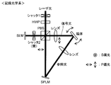
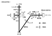
- FIG. 1 is a perspective view showing a schematic configuration of a vector wave recording medium in an embodiment. It is a schematic block diagram which shows an example of the optical apparatus for performing vector wave multiplex recording in a holographic manner. It is a schematic block diagram which shows an example of the reproduction
- eta relative diffraction intensity
- FIG. 1 is a perspective view showing a schematic configuration of a vector wave recording medium in the present embodiment.
- the vector wave recording medium 10 of the present embodiment has an information recording layer 12 made of a light-induced birefringent material formed on a transparent substrate 11.
- the transparent substrate 11 is made of, for example, glass or resin, but is preferably resin from the viewpoint of moldability and cost.
- the resin include polycarbonate resin, acrylic resin, epoxy resin, polystyrene resin, acrylonitrile-styrene copolymer, polyethylene resin, polypropylene resin, silicone resin, fluorine resin, ABS resin, urethane resin, and the like.
- polycarbonate resin and acrylic resin are particularly preferable from the viewpoints of moldability, optical characteristics, and cost.
- the surface of the transparent substrate 11 can be finely processed as necessary, and can be hard-coated with a UV curable resin or the like. Furthermore, antireflection treatment can also be performed.
- the thickness of the transparent substrate 11 is appropriately set to a thickness that does not affect recording and reproduction on the vector wave recording medium 10, that is, the information recording medium 12.
- the information recording layer 12 includes a polymer matrix and a photo radical generator.
- the polymer matrix and the photoradical generator may be dissolved in a solvent and applied to the transparent substrate 11 and dried, or the polymer matrix and the photoradical generator may be melt-kneaded and molded. It may be formed.
- the type of polymer matrix is not particularly limited, but acrylic resins such as polyacrylates, polyvinyl resins, polyolefin resins, polyacetal resins, cellulose resins, polyurethane resins, polyamide resins, polyester resins, polycarbonate resins, phenoxy Resins, phenol resins, epoxy resins, polyimide resins, various elastomers and the like can be mentioned. These may be used alone or in combination of two or more or a copolymer.
- the polymer matrix is preferably optically transparent, and particularly preferably has a small birefringence.
- the photo radical generator is not particularly limited as long as it generates radical species by light irradiation, and examples thereof include a group of compounds generally known as photo radical polymerization initiators. These may be used alone or in combination of two or more. Photoradical generators are roughly classified into intramolecular cleavage type photoradical generators and hydrogen abstraction type photoradical generators, and the former is preferred for the present invention. As the intramolecular cleavage type photo radical generator, an ⁇ -aminoacetophenone compound or an oxime ester compound is preferably used.
- the ⁇ -aminoacetophenone compound may be used alone or in combination of two or more.
- Specific examples of the ⁇ -aminoacetophenone compound include the following compounds.
- One oxime ester compound may be used alone, or two or more oxime ester compounds may be used in combination.
- Specific examples of the oxime ester compound include the following compounds.
- the transparent substrate 11 is provided, but the polymer matrix is made of, for example, thermosetting resin such as phenol resin or epoxy resin, engineering plastic such as polycarbonate, and so on and has sufficient strength. In such a case, the transparent substrate 11 can be omitted.
- the thickness of the information recording layer 12 is preferably in the range of 1 to 3,000 ⁇ m.
- the transmittance in the recording wavelength region of 350 nm to 800 nm is high, and recording can be performed sufficiently even with relatively low energy recording signal light and recording reference light, and energy efficiency can be increased.
- the surface of the information recording layer 12 can be finely processed as necessary, and can be hard-coated with a UV curable resin or the like. Furthermore, antireflection treatment can also be performed.
- the ratio ( ⁇ min / ⁇ max) of the minimum value ⁇ min to the maximum value ⁇ max needs to be 0.1 or more, preferably 0.2 or more, particularly preferably 0.3 or more.
- the ratio ( ⁇ min / ⁇ max) of the reproduction signal light described above to the maximum value ⁇ max of the minimum value ⁇ min in the diffraction efficiency can be achieved by configuring the information recording layer 12 from the above-described material.
- it can be easily realized by using an intramolecular cleavage type photo radical generator of an ⁇ -aminoacetophenone compound or an oxime ester compound as a photo radical polymerization initiator.
- the upper limit of the ratio ( ⁇ min / ⁇ max) of the minimum value ⁇ min to the maximum value ⁇ max is ideally 1, it is approximately 0.7 as long as the above-described materials are used at present.
- the transmissive vector wave recording medium 10 has been described as shown in FIG. 1, but a reflective layer is formed on the surface of the transparent substrate 11 opposite to the surface on which the information recording layer 12 is formed.
- a reflective vector wave recording medium can be obtained.
- a coherent recording signal light 21 and a recording reference light 22 are simultaneously irradiated onto the same area of the information recording layer 12.
- the polarization direction is spatially and periodically modulated in the same region of the information recording layer 12 so that a linearly polarized light portion of ⁇ 45 degrees is obtained.
- 12A and circularly polarized light portions 12B appear alternately and periodically.
- the light intensity distribution in the information recording layer 12 is uniform, but birefringence is imparted to the light-induced birefringence material, for example, corresponding to the modulated polarization direction.
- a birefringent grating having spatially different absorptivity or refractive index and distributed in ⁇ 45 degrees is formed as a hologram in accordance with the linearly polarized light of ⁇ 45 degrees. Is done.
- the Bragg condition is changed in the vector wave recording medium 10, that is, the information recording layer 12, and the irradiation of the recording signal light 21 and the recording reference light 22 is performed with the irradiation energy constant, in the same manner as described above. Perform on the same area.
- the polarization direction of the information recording layer 12 is spatially and periodically modulated, and ⁇ 45 degrees linearly polarized light portions 12A 'and circularly polarized light portions 12B' appear alternately and periodically.
- the light intensity distribution in the information recording layer 12 is uniform, but a part of the light-induced birefringent material constituting the information recording layer 12 facing the same direction as the modulated polarization direction is in another direction. It is more strongly photoexcited than part of the light-induced birefringent material that faces it.
- a birefringent grating having spatially different absorptivity or refractive index according to ⁇ 45 degrees of linearly polarized light and distributed in ⁇ 45 degrees is used as a hologram. It is formed.
- the recording signal light 21 and the recording reference light 22 are irradiated with the irradiation energy constant, the Bragg conditions are changed in the information recording layer 12 and sequentially performed, whereby each diffraction grating is recorded as recording information.
- holographic vector wave multiplex recording on the information recording layer 12 can be performed.
- the polarization states of the recording signal light 21 and the recording reference light 22 with respect to different diffraction gratings of the information recording layer 12 are constant for p-polarized light and s-polarized light, respectively.
- the polarization state of the reference light 22 can also be changed.
- the information recording layer 12 on which holographic vector wave multiplex recording has been performed as described above is irradiated with s-polarized reproduction reference light 23 from the front side or the back side. Then, diffracted light is obtained from each diffraction grating on which holographic vector wave recording has been performed. At this time, the diffracted light becomes p-polarized light that is 90 degrees different from the incident light.
- the information recording layer 12, that is, the vector wave recording medium is reproduced (read) by irradiating the reproduction reference light 23 to each diffraction grating of the information recording layer 12 on which holographic vector wave multiplex recording has been performed. be able to.
- the vector wave recording medium 10 shown in FIG. 1 is a transmission type
- the principle of recording / reproducing with respect to the transmission type vector wave recording medium has been described.
- the only difference is that the reproduction reference beam 23 is emitted from the irradiation side of the recording signal beam 21 and the recording reference beam 22 of the information recording layer 12, and the other operations are related to a transmission type vector wave recording medium. This is the same as the recording / reproducing principle.
- FIG. 2 is a schematic configuration diagram showing an example of a recording optical system used for holographic vector wave multiplex recording according to the present invention.
- FIG. 3 shows reading of recorded information after performing holographic vector wave multiplex recording. It is a schematic block diagram which shows an example of the reproduction
- an optical system as shown in FIG. 2 is used to perform the above-described holographic vector wave multiplex recording.
- the laser light passes through the shutter 1 and the HWP (1/2 wavelength plate), and then is divided into two by PBS (polarization beam splitter), one of which passes through the shutter 2 as recording signal light, and then the SLM ( After being reflected by the spatial light modulator) and passing through the PBS, the vector wave recording medium is irradiated.
- the p-polarized light and the s-polarized light are mixed in the light reflected by the SLM, but only the p-polarized component can pass through the PBS. Therefore, the p-polarized component is transmitted to the recording medium via the lens as signal light. Irradiate.
- the other divided by the PBS is reflected by a SPLM (spatial polarization modulator) as recording reference light, and is irradiated onto the vector wave recording medium through the lens.
- the polarization state of the recording reference light is controlled by the SPLM so as to be s-polarized light orthogonal to the polarization state of the recording signal light.
- the polarization direction is spatially and periodically modulated in the information recording layer of the vector wave recording medium, and ⁇ 45 degree linearly polarized light portions and circularly polarized light portions appear alternately and periodically. .
- a birefringent diffraction grating having a spatially different absorptivity or refractive index distributed in ⁇ 45 degrees is formed as a hologram in accordance with ⁇ 45 degrees of linearly polarized light.
- the angle of the vector wave recording medium is changed using a control system (not shown), and the above operation is performed on the vector wave recording medium, that is, the information recording layer. That is, holographic vector wave multiplex recording on a vector wave recording medium is performed.
- an optical system as shown in FIG. 3 is used. This optical system is based on the optical system shown in FIG. 2, and an imaging optical system, a polarizing plate, and an imager for forming an image of reproduction light (diffracted light) after being transmitted (diffracted) through the recording medium are added. Is.
- the shutter 2 is closed, the laser light transmitted through the shutter 1, HWP, and PBS is reflected by SPLM to be s-polarized reproduction reference light, which is irradiated onto the vector wave recording medium. To do.
- the diffracted light is imaged by the imaging lens, and then only the p-polarized light is transmitted by the polarizing plate and is incident on the imager to analyze the recorded information.
- Example 1 10.0 parts by mass of Irgacure 379 (BASF) as a photoradical generator and 40.9 parts by mass of dicyclohexylmethane-4,4′-diisocyanate (manufactured by Tokyo Chemical Industry Co., Ltd.) as a polymer matrix forming material
- a recording material precursor comprising 49.1 parts by mass of pentaerythritol propoxylate (average molecular weight 629: manufactured by Aldrich) and 0.07 parts by mass of dibutyltin dilaurate (manufactured by Tokyo Chemical Industry Co., Ltd.) as a curing catalyst was prepared.
- This recording material precursor is injected into a gap between two glass substrates (30 mm ⁇ 30 mm, thickness 1.1 mm) bonded together via a silicon film spacer (thickness 1.0 mm), and is 55 ° C. in a nitrogen atmosphere. Heat treatment was performed for 3 hours. As a result, a vector wave recording medium A in which an information recording layer made of a light-induced birefringent material was formed between two glass substrates was obtained.
- Example 2 As a polymer matrix forming material, 49.7 parts by mass of dicyclohexylmethane-4,4′-diisocyanate (manufactured by Tokyo Chemical Industry Co., Ltd.) and pentaerythritol propoxylate (average molecular weight 426: manufactured by Aldrich) 40.3 masses A vector wave recording medium B was obtained in the same manner as in Example 1 except that the part was used.
- Example 3 As a photo radical generator, Irgacure 379 (manufactured by BASF) 5.0 parts by mass, as a polymer matrix, 43.2 parts by mass of dicyclohexylmethane-4,4′-diisocyanate (manufactured by Tokyo Chemical Industry Co., Ltd.), and A vector wave recording medium C was obtained in the same manner as in Example 1 except that 51.8 parts by mass of pentaerythritol propoxylate (average molecular weight 629: manufactured by Aldrich) was used.
- Example 4 15.0 parts by mass of Irgacure 379 (manufactured by BASF) as a photo radical generator and 38.7 parts by mass of dicyclohexylmethane-4,4′-diisocyanate (manufactured by Tokyo Chemical Industry Co., Ltd.) as a polymer matrix forming material
- a vector wave recording medium D was obtained in the same manner as in Example 1 except that 46.3 parts by mass of pentaerythritol propoxylate (average molecular weight 629: manufactured by Aldrich) was used.
- Example 5 10.0 parts by mass of Irgacure OXE01 (manufactured by BASF) as a photo radical generator and 40.9 parts by mass of dicyclohexylmethane-4,4′-diisocyanate (manufactured by Tokyo Chemical Industry Co., Ltd.) as a polymer matrix forming material
- a vector wave recording medium E was obtained in the same manner as in Example 1 except that 49.1 parts by mass of pentaerythritol propoxylate (average molecular weight 629: manufactured by Aldrich) was used.
- thermopolymerization monomer 1.0 part by mass of 9,10-phenanthrenequinone (manufactured by Tokyo Chemical Industry Co., Ltd.) and 98.6 mass by weight of methyl methacrylate (manufactured by Wako Pure Chemical Industries, Ltd.) as thermal polymerization monomer.
- a recording material precursor comprising 0.4 parts by mass of 2,2′-azobis (isobutyronitrile) as a thermal polymerization initiator was prepared. After the recording material precursor was heated at 60 ° C. for 2 hours, two glass plates (50 mm ⁇ 50 mm, thickness 1.2 mm) bonded together via a silicon spacer (thickness 1.0 mm) cut out in a concave shape were used. It was introduced into the gap. Thereafter, heat treatment was performed at 60 ° C. for 6 hours, and the two glass plates were removed to obtain a recording medium F.
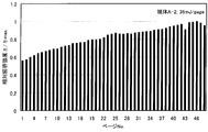
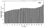
- ⁇ Measurement results> 4 to 11 show that there is no scheduling for the recording media A to F obtained in the examples and comparative examples (that is, the recording signal light for each diffraction grating corresponding to the recording information by changing the Bragg condition). And relative recording intensity ⁇ / ⁇ max from each diffraction grating when holographic vector wave multiplex recording is performed and 48 multiplex recording is performed by irradiating recording reference light with the same energy).
- Table 1 shows ⁇ min / ⁇ max obtained from this data.
- 4 to 6 show the case where the irradiation energy of the recording signal light and the recording reference light is changed with respect to the recording medium A obtained in the embodiment. However, the irradiation energy for 48 multiple recording is the same throughout the multiple recording.
- ⁇ min / ⁇ max of the recording media A to E obtained in this example is 0.3 or more, and scheduling is essential in the 48 multiplex recording. You can see that it is not necessary.
- ⁇ min / ⁇ max is a low value of 0.012, and it can be seen that scheduling is necessary in the 48 multiplex recording.
Landscapes
- Physics & Mathematics (AREA)
- General Physics & Mathematics (AREA)
- Holo Graphy (AREA)
- Optical Recording Or Reproduction (AREA)
- Optical Record Carriers And Manufacture Thereof (AREA)
Abstract
光誘起複屈折材料からなる情報記録層を有し、第1の偏光状態の記録信号光及び前記第1の偏光状態と異なる第2の偏光状態の記録参照光を照射し、前記情報記録層に対してホログラフィックにベクトル波多重記録を行なうベクトル波記録媒体であって、前記記録信号光及び前記記録参照光の照射エネルギーを一定として、前記情報記録層に対して前記ベクトル波多重記録をホログラフィックに実施した後の、前記情報記録層における各記録情報に相当する各回折格子からの再生信号光の回折効率の最大値をηmax、最小値をηminとしたとき、ηmin/ηmax≧0.1を満たすようにする。これによって、スケジューリングを行う必要がなく、記録システム上の転送レートの低下を引き起こす恐れのないベクトル波記録媒体及びその多重記録再生方法の提供が可能となる。
Description
本発明は、照射される光の偏光状態に応じて屈折率の異方性を生じる光誘起複屈折材料からなる情報記録層を有し、ホログラフィックにベクトル波多重記録を行なうためのベクトル波記録媒体、及びその多重記録再生方法に関する。
ホログラフィック記録は、イメージ情報を持った信号光とともに参照光を同時に照射して生じる干渉縞を、記録媒体に回折格子として記録することにより行われる。ホログラフィック記録媒体からの再生は、上記したイメージ情報が記録された記録媒体に参照光を照射して、イメージ情報を回折格子からの再生信号光として読み出すことによって行われる。
ホログラフィック記録は、上記イメージ情報を1ページとして、ページ単位で一括記録、再生でき、かつ、媒体の同一箇所にページを多重記録できることから、従来のCD、DVD、ブルーレイディスクで用いられるビット・バイ・ビットの記録方式に替わる高速かつ大容量の光記録方式として期待される技術である。
一方、照射される光の偏光状態に応じて屈折率の異方性を生じる光誘起複屈折材料からなる情報記録層を有する偏光記録媒体を用いて、イメージ情報を複屈折位相差(リターデーション)として記録する新たな偏光記録方式(リターダグラフィー)が提案されている(特許文献1参照)。また、イメージ情報を有する信号光とともに信号光とは異なる偏光状態の参照光を同時に照射して生じる偏光分布を上記偏光記録媒体に記録するベクトル波記録方式も提案されている。これは、ホログラフィック記録と偏光記録とを組み合わせることで、更なる高記録密度化が期待されるものである(特許文献2参照)。
ところでホログラフィック記録、偏光記録に用いる記録材料は、ライトワンス型と書き換え型との2つに大別される。ライトワンス型および書き換え型の偏光記録材料に用いられる偏光感応性化合物としては、それぞれ、9,10-フェナンスレンキノン、アゾベンゼン等が広く知られている。
ライトワンス型の記録材料を用いて多重記録が行なわれる場合、1ページ目の記録によって、記録成分がある割合で光反応して変化し、2ページ目の記録によって、残りの未反応の記録成分がある割合で光反応して変化し、3ページ目の記録によって、更に残りの未反応の記録成分がある割合で光反応して変化し、・・・、が順次繰り返されて多重記録が行なわれる。
従って、多重が繰り返されるほど残存記録成分が減少するので、それにともない記録感度が低下する。つまり、各ページを同じ照射エネルギーで記録すると、後半のページにいくほど再生信号強度が減少することになり、記録再生システム上不都合が生じる。
一方、書き換え型の記録材料を用いて多重記録が行なわれる場合は、1ページ目の記録によって、記録成分がある割合で光反応して変化し、2ページ目の記録によって、1ページ目のすでに記録に消費された成分と残りの未反応の記録成分とがそれぞれある割合で光反応して変化し、3ページ目の記録によって、1ページ目と2ページ目のすでに記録に消費された成分と残りの未反応の記録成分がそれぞれある割合で光反応して変化し、・・・、が順次繰り返されて多重記録が行なわれる。
従って、多重が繰り返されるほど、すでに記録されたページの記録成分が減少するので、各ページを同じ照射エネルギーで記録すると、ライトワンス型とは逆に、前半のページの再生信号強度が減少することになり、この場合も記録再生システム上不都合が生じる。
これらの不都合を解消するために、スケジューリングと呼ばれる手法が用いられる。これは、多重による再生信号強度の変化、つまり記録感度の変化を予め想定して、照射エネルギーをページ(回折格子)毎に変化させながら多重記録を行なうもので、これによって各ページからの再生信号強度を均一化しようとするものである(特許文献3参照)。
しかしながら、特許文献3に示される記録媒体は、ホログラフィック記録媒体であってベクトル波記録媒体ではないため、大幅な記録密度の向上が期待できない。また、特許文献3に示される記録媒体は、スケジューリングを確実に行うことを目的とするものであって、スケジューリング自体は依然必要である。
スケジューリングを行った場合、感度の低下が予想されるページ(回折格子)に対しては高い照射エネルギーで記録することになる。照射エネルギーは照射パワーと照射時間との掛け算であるが、照射パワーをページ毎に変化させるには記録システム上複雑な制御が要求されるため、照射時間を調整して照射エネルギーを変化させるのが一般的である。
つまり、高い照射エネルギーで記録するためには照射時間を長くすることになり、これは記録システム上の転送レートの低下を引き起こすという問題につながる。
本発明は、スケジューリングを行う必要がなく、これによって記録システム上の転送レートの低下を引き起こす恐れのないベクトル波記録媒体及びその多重記録再生方法を提供することを目的とする。
上記目的を達成すべく、本発明は、光誘起複屈折材料からなる情報記録層を有し、第1の偏光状態の記録信号光及び前記第1の偏光状態と異なる第2の偏光状態の記録参照光を照射し、前記情報記録層に対してホログラフィックにベクトル波多重記録を行なうベクトル波記録媒体であって、前記記録信号光及び前記記録参照光の照射エネルギーを一定として、前記情報記録層に対して前記ベクトル波多重記録をホログラフィックに実施した後の、前記情報記録層における各記録情報に相当する各回折格子からの再生信号光の回折効率の最大値をηmax、最小値をηminとしたとき、ηmin/ηmax≧0.1を満たすことを特徴とする、ベクトル波記録媒体に関する。
また、本発明は、光誘起複屈折材料からなる情報記録層を有するベクトル波記録媒体に対して、第1の偏光状態の記録信号光及び前記第1の偏光状態と異なる第2の偏光状態の記録参照光を、前記記録信号光及び前記記録参照光の照射エネルギーを一定として照射し、前記情報記録層に対してホログラフィックにベクトル波多重記録を行なうステップと、前記ベクトル波記録媒体に対して前記第2の偏光状態の再生参照光を照射し、前記情報記録層における各記録情報に相当する各回折格子からの再生信号光を得るステップとを具え、再生信号光の回折効率の最大値をηmax、最小値をηminとしたとき、ηmin/ηmax≧0.1を満たすことを特徴とする、ベクトル波記録媒体の多重記録再生方法に関する。
なお、ηは、入射光、すなわち記録信号光及び記録参照光の光強度I0に対する各回折格子からの再生信号光の光強度I1の比η=I1/I0として定義される。
本発明のベクトル波記録媒体及びその多重記録再生方法によれば、光誘起複屈折材料からなる情報記録層を有するベクトル波記録媒体に対して、第1の偏光状態の記録信号光及び第1の偏光状態と異なる第2の偏光状態の記録参照光を照射し、情報記録層に対してホログラフィックにベクトル波多重記録を行うに際して、記録信号光及び記録参照光の照射エネルギーを一定とした場合における、各記録情報に相当する各回折格子の再生信号光の回折効率において、最大値ηmaxの最小値ηminに対する比率を0.1以上としている。
すなわち、記録信号光及び記録参照光の照射エネルギーを一定とし、特にスケジューリングを行わない場合においても、ホログラフィックなベクトル波多重記録において、再生信号光の回折効率、すなわち再生信号光の強度が大きく減少することがない。結果として、感度の低下が予想されるページ(回折格子)に対して高い照射エネルギーで記録するような操作が要求されないので、照射時間を長くする必要がなくなり、記録システム上の転送レートの低下を抑制することができる。
本発明の一例において、光誘起複屈折材料は、光ラジカル発生剤及びポリマーマトリックスを含む材料とすることができる。また、光ラジカル発生剤は、分子内開裂型光ラジカル発生剤とすることができる。さらに、分子内開裂型光ラジカル発生剤は、α-アミノアセトフェノン化合物又はオキシムエステル化合物とすることができる。
以上、本発明によれば、スケジューリングを行う必要がなく、これによって記録システム上の転送レートの低下を引き起こす恐れのないベクトル波記録媒体及びその多重記録再生方法を提供することができる。
以下、本発明に係る実施の形態について、図面を参照して詳細に説明する。
(ベクトル波記録媒体)
最初に、本発明のベクトル波記録媒体の一例について説明する。図1は、本実施形態におけるベクトル波記録媒体の概略構成を示す斜視図である。図1に示すように、本実施形態のベクトル波記録媒体10は、透明基板11上に光誘起複屈折材料からなる情報記録層12が形成されてなる。
最初に、本発明のベクトル波記録媒体の一例について説明する。図1は、本実施形態におけるベクトル波記録媒体の概略構成を示す斜視図である。図1に示すように、本実施形態のベクトル波記録媒体10は、透明基板11上に光誘起複屈折材料からなる情報記録層12が形成されてなる。
透明基板11は、例えば、ガラス、樹脂などが用いられるが、成形性、コストの点から、樹脂が好ましい。樹脂としては、例えば、ポリカーボネート樹脂、アクリル樹脂、エポキシ樹脂、ポリスチレン樹脂、アクリロニトリル-スチレン共重合体、ポリエチレン樹脂、ポリプロピレン樹脂、シリコーン樹脂、フッ素樹脂、ABS樹脂、ウレタン樹脂、などが挙げられる。これらの中でも、成形性、光学特性、コストの点から、ポリカーボネート樹脂、アクリル樹脂が特に好ましい。
また、透明基板11の表面には、必要に応じて微細加工を施すことができ、またUV硬化樹脂等でハードコート処理することもできる。さらには、反射防止処理をすることもできる。
また、以下に示す記録及び再生に影響を与えない限りにおいてセラミック等からも構成することができる。
透明基板11の厚さは、ベクトル波記録媒体10、すなわち情報記録媒体12に対する記録及び再生に影響を与えないような厚さに適宜に設定する。
情報記録層12は、ポリマーマトリックス及び光ラジカル発生剤を含む。具体的には、ポリマーマトリックス及び光ラジカル発生剤を溶媒に溶解させ、透明基板11に塗布乾燥することで形成させてもよいし、ポリマーマトリックスと光ラジカル発生剤とを溶融混練し成型することで形成させてもよい。
ポリマーマトリックスの種類は特に限定されるものではないが、ポリアクリル酸エステル等のアクリル系樹脂、ポリビニル樹脂、ポリオレフィン樹脂、ポリアセタール樹脂、セルロース系樹脂、ポリウレタン樹脂、ポリアミド樹脂、ポリエステル樹脂、ポリカーボネート樹脂、フェノキシ樹脂、フェノール樹脂、エポキシ樹脂、ポリイミド樹脂、各種エストラマー等が挙げられる。これらは単独で用いても、2種以上を混合、もしくは共重合体を用いてもよい。ポリマーマトリックスとしては、光学的に透明なものが好ましく、特に複屈折が小さなものが好ましい。
光ラジカル発生剤は光照射によりラジカル種を生成するものであれば特に限定されるものではないが、光ラジカル重合開始剤として一般的に知られている化合物群が挙げられる。これらは単独で用いても、2種以上を混合して使用してもよい。光ラジカル発生剤は分子内開裂型光ラジカル発生剤と水素引き抜き型光ラジカル発生剤とに大別されるが、本発明には前者が好ましい。分子内開裂型光ラジカル発生剤としては、α-アミノアセトフェノン化合物又はオキシムエステル化合物を用いることが好ましい。
α-アミノアセトフェノン化合物は1種を単独で使用してもよいし、2種以上を併用することもできる。α-アミノアセトフェノン化合物として、具体的には、以下の化合物が例示できる。
例えば、2-ジメチルアミノ-2-メチル-1-フェニルプロパン-1-オン、2-ジエチルアミノ-2-メチル-1-フェニルプロパン-1-オン、2-メチル-2-モルホリノ-1-フェニルプロパン-1-オン、2-ジメチルアミノ-2-メチル-1-(4-メチルフェニル)プロパン-1-オン、2-ジメチルアミノ-1-(4-エチルフェニル)-2-メチルプロパン-1-オン、2-ジメチルアミノ-1-(4-イソプロピルフェニル)-2-メチルプロパン-1-オン、1-(4-ブチルフェニル)-2-ジメチルアミノ-2-メチルプロパン-1-オン、2-ジメチルアミノ-1-(4-メトキシフェニル)-2-メチルプロパン-1-オン、2-ジメチルアミノ-2-メチル-1-(4-メチルチオフェニル)プロパン-1-オン、2-メチル-1-(4-メチルチオフェニル)-2-モルホリノプロパン-1-オン(イルガキュア907)、2-ベンジル-2-ジメチルアミノ-1-(4-モルホリノフェニル)ブタン-1-オン(イルガキュア369)、2-ベンジル-2-ジメチルアミノ-1-(4-ジメチルアミノフェニル)ブタン-1-オン、2-ジメチルアミノ-2-[(4-メチルフェニル)メチル]-1-(4-モルホリノフェニル)ブタン-1-オン(イルガキュア379)などが挙げられる。
オキシムエステル化合物は1種を単独で使用してもよいし、2種以上を併用することもできる。オキシムエステル化合物として、具体的には、以下の化合物が例示できる。
例えば、3-ベンゾイルオキシイミノブタン-2-オン、3-アセトキシイミノブタン-2-オン、3-プロピオニルオキシイミノブタン-2-オン、2-アセトキシイミノペンタン-3-オン、2-アセトキシイミノ-1-フェニルプロパン-1-オン、2-ベンゾイルオキシイミノ-1-フェニルプロパン-1-オン、3-p-トルエンスルホニルオキシイミノブタン-2-オン、2-エトキシカルボニルオキシイミノ-1-フェニルプロパン-1-オン、1-(4-フェニルチオ)フェニル-2-ベンゾイルオキシイミノオクタン-1-オン(イルガキュアOXE01)、1-[9-エチル-6-(2-メチルベンゾイル)カルバゾール-3-イル]-1-アセトキシイミノエタン(イルガキュアOXE02)等が挙げられる。
なお、本実施形態では、透明基板11を設けているが、ポリマーマトリックスを例えばフェノール樹脂やエポキシ樹脂等の熱硬化性樹脂、ポリカーボネート等のエンジニアリングプラスチックから構成し、それ自体で十分な強度を有するような場合においては、透明基板11を省略することができる。
情報記録層12の厚さは1~3,000μmの範囲であることが好ましい。この場合、記録波長領域350nm~800nmでの透過率が高く、比較的低エネルギーの記録信号光及び記録参照光でも十分に記録を行うことができ、エネルギー効率を増大させることができる。
情報記録層12の表面には、必要に応じて微細加工を施すことができ、またUV硬化樹脂等でハードコート処理することもできる。さらには、反射防止処理をすることもできる。
本発明では、情報記録層12に対してホログラフィックにベクトル波多重記録を行うに際して、記録信号光及び記録参照光の照射エネルギーを一定とした場合における、各記録情報に相当する各回折格子の再生信号光の回折効率において、最小値ηminの最大値ηmaxに対する比率(ηmin/ηmax)が0.1以上であることが必要であり、0.2以上が好ましく、特に0.3以上が特に好ましい。
これによって、記録信号光及び記録参照光の照射エネルギーを一定とし、特にスケジューリングを行わない場合においても、ホログラフィックなベクトル波多重記録において、再生信号光の回折効率、すなわち再生信号光の強度が大きく減少することがない。結果として、感度の低下が予想されるページに対して高い照射エネルギーで記録するような操作が要求されないので、高い照射エネルギーで記録するために照射時間を長くする必要がなくなり、記録システム上の転送レートの低下を抑制することができる。
なお、上述した再生信号光の、回折効率における最小値ηminの最大値ηmaxに対する比率(ηmin/ηmax)は、情報記録層12を上述した材料から構成することにより達成することができる。特に、光ラジカル重合開始剤として、α-アミノアセトフェノン化合物又はオキシムエステル化合物の分子内開裂型光ラジカル発生剤を用いることにより、容易に実現することができる。
なお、最小値ηminの最大値ηmaxに対する比率(ηmin/ηmax)の上限値は1であることが理想的ではあるが、現状において上述した材料を使用する限りにおいては、0.7程度である。
本実施形態では、図1に示すように、透過型のベクトル波記録媒体10について説明したが、透明基板11の、情報記録層12が形成された面と相対する面上に反射層を形成することによって、反射型のベクトル波記録媒体とすることもできる。
(ホログラフィックなベクトル波多重記録及びその再生)
次に、図1を参照して、ホログラフィックなベクトル波多重記録及びその再生の原理の概略について説明する。
次に、図1を参照して、ホログラフィックなベクトル波多重記録及びその再生の原理の概略について説明する。
図1に示すように、ベクトル波記録媒体10に対して記録を行うに際しては、コヒーレントな記録信号光21及び記録参照光22を、情報記録層12の同一領域に同時に照射する。
例えば、記録信号光21をp偏光とし、記録参照光22をs偏光とすると、上記情報記録層12の同一領域では、偏光方向が空間的・周期的に変調され、±45度の直線偏光部分12Aと円偏光部分12Bとが交互に周期的に現れる。
この場合、情報記録層12における光強度分布は一様となるが、例えば変調された偏光方向に対応して、光誘起複屈折材料に複屈折が付与される。その結果、直線偏光部分12Aでは、±45度の直線偏光に応じて、空間的に方向性の異なる吸収率または屈折率であって、±45度に分布した複屈折性の格子がホログラムとして形成される。
次いで、ベクトル波記録媒体10、すなわち情報記録層12においてブラッグ条件を変化させ、記録信号光21及び記録参照光22の照射を、それらの照射エネルギーを一定として、上記同様にして情報記録層12の同一領域に対して行う。これによって、情報記録層12の偏光方向が空間的・周期的に変調され、±45度の直線偏光部分12A’と円偏光部分12B’とが交互に周期的に現れる。
この場合、情報記録層12における光強度分布は一様となるが、変調された偏光方向と同一の方向を向く情報記録層12を構成する光誘起複屈折材料の一部が、他の方向を向く光誘起複屈折材料の一部より強く光励起される。その結果、直線偏光部分12A’では、±45度の直線偏光に応じて、空間的に方向性の異なる吸収率または屈折率であって、±45度に分布した複屈折性の格子がホログラムとして形成される。
このように、記録信号光21及び記録参照光22の照射を、それらの照射エネルギーを一定として、情報記録層12においてブラッグ条件を変化させ、順次に行うことにより、各回折格子がそれぞれ記録情報として機能することになり、情報記録層12へのホログラフィックなベクトル波多重記録を行うことができる。
なお、上記においては、情報記録層12の異なる回折格子に対して記録信号光21及び記録参照光22の偏光状態を、それぞれp偏光及びs偏光で一定としたが、それら記録信号光21及び記録参照光22の偏光状態を変化させることもできる。
次いで、上述のようにしてホログラフィックにベクトル波多重記録がなされた情報記録層12に対して、s偏光の再生参照光23をその表面側あるいは裏面側から照射する。すると、ホログラフィックにベクトル波記録がなされた各回折格子から回折光が得られる。このとき、回折光は入射光と90度異なるp偏光となる。このように、ホログラフィックにベクトル波多重記録がなされた情報記録層12の回折格子毎に再生参照光23を照射することによって、情報記録層12、すなわちベクトル波記録媒体の再生(読み出し)を行うことができる。
なお、上記においては、図1に示すベクトル波記録媒体10が透過型であることから、透過型のベクトル波記録媒体に関する記録再生の原理について述べたが、反射型のベクトル波記録媒体に関する記録再生についても、再生参照光23を、情報記録層12の、記録信号光21及び記録参照光22の照射側から射する点で異なるのみであり、その他の操作については透過型のベクトル波記録媒体に関する記録再生原理と同様である。
(ホログラフィックなベクトル波多重記録及びその再生の具体例)
図2は、本発明のホログラフィックなベクトル波多重記録に用いる記録光学系の一例を示す概略構成図であり、図3は、ホログラフィックなベクトル波多重記録を実施した後の、記録情報の読み出しに使用する再生光学系の一例を示す概略構成図である。
図2は、本発明のホログラフィックなベクトル波多重記録に用いる記録光学系の一例を示す概略構成図であり、図3は、ホログラフィックなベクトル波多重記録を実施した後の、記録情報の読み出しに使用する再生光学系の一例を示す概略構成図である。
上述したホログラフィックなベクトル波多重記録を行うためには、例えば図2に示すような光学系を用いる。この光学系では、レーザ光がシャッタ1、HWP(1/2波長板)を通過した後、PBS(偏光ビームスプリッタ)で2分割され、一方は記録信号光としてシャッタ2を通過した後、SLM(空間光変調器)で反射され、PBSを透過した後、ベクトル波記録媒体に照射される。この場合、SLMで反射された光は、p偏光とs偏光とが混在しているが、p偏光成分のみがPBSを透過できるので、このp偏光成分を信号光としてレンズを介し、記録媒体に照射する。
また、PBSで分割された他方は、記録参照光としてSPLM(空間偏光変調器)で反射され、レンズを介してベクトル波記録媒体に照射される。この際、SPLMによって、記録参照光の偏光状態が記録信号光の偏光状態と直交するs偏光となるように制御される。これによって、上述したように、ベクトル波記録媒体の情報記録層には、偏光方向が空間的・周期的に変調され、±45度の直線偏光部分と円偏光部分とが交互に周期的に現れる。そして、直線偏光部分では、±45度の直線偏光に応じて、空間的に方向性の異なる吸収率または屈折率であって、±45度に分布した複屈折性の回折格子がホログラムとして形成される。
次いで、図2に示す光学系において、図示しない制御系を用い、ベクトル波記録媒体の角度を変化させ、このベクトル波記録媒体、すなわち情報記録層に対して上述した操作を行い、情報記録層、すなわちベクトル波記録媒体へのホログラフィックなベクトル波多重記録を行う。
また、上述のようにしてホログラフィックにベクトル波多重記録を実施したベクトル波記録媒体、すなわち情報記録層から信号を読み出す(再生する)に際しては、例えば図3に示すような光学系を用いる。この光学系は、図2に示す光学系を基本とし、記録媒体を透過(回折)した後の再生光(回折光)を結像させるための結像光学系、偏光板及びイメージャが付加されたものである。
図3に示す光学系を用いた再生操作は、シャッタ2を閉とし、シャッタ1、HWP、PBSを透過したレーザ光をSPLMで反射させてs偏光の再生参照光とし、ベクトル波記録媒体に照射する。
ベクトル波記録媒体からは、上述したように、ホログラフィックにベクトル波多重記録がなされた各回折格子から回折光が得られる。このとき、回折光は入射光と90度異なるp偏光となる。次いで、図示しない制御系でベクトル波記録媒体の角度を変化させ、同様にしてs偏光の再生参照光を、ホログラフィックにベクトル波多重記録がなされた回折格子毎に照射することによって、ホログラフィックにベクトル波多重記録がなされたベクトル波記録媒体、すなわち情報記録層の再生(読み出し)を行うことができる。
なお、回折光は、結像レンズで結像させた後、偏光板でp偏光のみを透過させ、イメージャに入射させ、記録情報の解析を行う。
(実施例1)
光ラジカル発生剤として、イルガキュア379(BASF社製)10.0質量部、ポリマーマトリックス形成材料として、ジシクロヘキシルメタン-4,4’-ジイソシアナート40.9質量部(東京化成工業(株)製)、及びペンタエリスリトールプロポキシラート(平均分子量629:Aldrich社製)49.1質量部、硬化触媒としてジブチルスズジラウレート(東京化成工業(株)製)0.07質量部からなる記録材料前駆体を調製した。
光ラジカル発生剤として、イルガキュア379(BASF社製)10.0質量部、ポリマーマトリックス形成材料として、ジシクロヘキシルメタン-4,4’-ジイソシアナート40.9質量部(東京化成工業(株)製)、及びペンタエリスリトールプロポキシラート(平均分子量629:Aldrich社製)49.1質量部、硬化触媒としてジブチルスズジラウレート(東京化成工業(株)製)0.07質量部からなる記録材料前駆体を調製した。
この記録材料前駆体を、シリコンフィルムスペーサー(厚み1.0mm)を介して貼り合わせた2枚のガラス基板(30mm×30mm、厚み1.1mm)の空隙に注入し、窒素雰囲気下、55℃で3時間加熱処理を施した。その結果、2枚のガラス基板の間に光誘起複屈折材料からなる情報記録層が形成されたベクトル波記録媒体Aを得た。
(実施例2)
ポリマーマトリックス形成材料として、ジシクロヘキシルメタン-4,4’-ジイソシアナート49.7質量部(東京化成工業(株)製)、及びペンタエリスリトールプロポキシラート(平均分子量426:Aldrich社製)40.3質量部を用いた以外は、実施例1と同様にしてベクトル波記録媒体Bを得た。
ポリマーマトリックス形成材料として、ジシクロヘキシルメタン-4,4’-ジイソシアナート49.7質量部(東京化成工業(株)製)、及びペンタエリスリトールプロポキシラート(平均分子量426:Aldrich社製)40.3質量部を用いた以外は、実施例1と同様にしてベクトル波記録媒体Bを得た。
(実施例3)
光ラジカル発生剤として、イルガキュア379(BASF社製)5.0質量部、ポリマーマトリックスとして、ジシクロヘキシルメタン-4,4’-ジイソシアナート43.2質量部(東京化成工業(株)製)、及びペンタエリスリトールプロポキシラート(平均分子量629:Aldrich社製)51.8質量部を用いた以外は、実施例1と同様にしてベクトル波記録媒体Cを得た。
光ラジカル発生剤として、イルガキュア379(BASF社製)5.0質量部、ポリマーマトリックスとして、ジシクロヘキシルメタン-4,4’-ジイソシアナート43.2質量部(東京化成工業(株)製)、及びペンタエリスリトールプロポキシラート(平均分子量629:Aldrich社製)51.8質量部を用いた以外は、実施例1と同様にしてベクトル波記録媒体Cを得た。
(実施例4)
光ラジカル発生剤として、イルガキュア379(BASF社製)15.0質量部、ポリマーマトリックス形成材料として、ジシクロヘキシルメタン-4,4’-ジイソシアナート38.7質量部(東京化成工業(株)製)、及びペンタエリスリトールプロポキシラート(平均分子量629:Aldrich社製)46.3質量部を用いた以外は、実施例1と同様にしてベクトル波記録媒体Dを得た。
光ラジカル発生剤として、イルガキュア379(BASF社製)15.0質量部、ポリマーマトリックス形成材料として、ジシクロヘキシルメタン-4,4’-ジイソシアナート38.7質量部(東京化成工業(株)製)、及びペンタエリスリトールプロポキシラート(平均分子量629:Aldrich社製)46.3質量部を用いた以外は、実施例1と同様にしてベクトル波記録媒体Dを得た。
(実施例5)
光ラジカル発生剤として、イルガキュアOXE01(BASF社製)10.0質量部、ポリマーマトリックス形成材料として、ジシクロヘキシルメタン-4,4’-ジイソシアナート40.9質量部(東京化成工業(株)製)、及びペンタエリスリトールプロポキシラート(平均分子量629:Aldrich社製)49.1質量部を用いた以外は、実施例1と同様にしてベクトル波記録媒体Eを得た。
光ラジカル発生剤として、イルガキュアOXE01(BASF社製)10.0質量部、ポリマーマトリックス形成材料として、ジシクロヘキシルメタン-4,4’-ジイソシアナート40.9質量部(東京化成工業(株)製)、及びペンタエリスリトールプロポキシラート(平均分子量629:Aldrich社製)49.1質量部を用いた以外は、実施例1と同様にしてベクトル波記録媒体Eを得た。
(比較例1)
偏光感応性化合物として、9,10-フェナンスレンキノン(東京化成工業(株)製)1.0質量部、熱重合モノマーとしてメタクリル酸メチル(和光純薬工業(株)製)98.6質量部、熱重合開始剤として2,2’-アゾビス(イソブチロニトリル)0.4質量部からなる記録材料前駆体を調製した。この記録材料前駆体を60℃で2時間加熱後、凹字型に切り出したシリコンスペーサー(厚み1.0mm)を介して貼り合わせた2枚のガラス板(50mm×50mm、厚み1.2mm)の空隙に導入した。その後、60℃で6時間加熱処理を行い、2枚のガラス板を取り外し、記録媒体Fを得た。
偏光感応性化合物として、9,10-フェナンスレンキノン(東京化成工業(株)製)1.0質量部、熱重合モノマーとしてメタクリル酸メチル(和光純薬工業(株)製)98.6質量部、熱重合開始剤として2,2’-アゾビス(イソブチロニトリル)0.4質量部からなる記録材料前駆体を調製した。この記録材料前駆体を60℃で2時間加熱後、凹字型に切り出したシリコンスペーサー(厚み1.0mm)を介して貼り合わせた2枚のガラス板(50mm×50mm、厚み1.2mm)の空隙に導入した。その後、60℃で6時間加熱処理を行い、2枚のガラス板を取り外し、記録媒体Fを得た。
<記録再生方法>
記録再生は、図2及び図3に示す光学系を用い、上述したような記録及び再生の手順に従って実施した。図2に示す記録光学系において、記録用の光源にはシングルモードで発振する波長405nmの半導体レーザを使用し、SLMは全画素全反射状態、PSLMは全画素90°偏光変調される状態とした。また、図3に示す再生光学系において、再生用の光源には、波長633nmのHe-Neレーザを使用した。
記録再生は、図2及び図3に示す光学系を用い、上述したような記録及び再生の手順に従って実施した。図2に示す記録光学系において、記録用の光源にはシングルモードで発振する波長405nmの半導体レーザを使用し、SLMは全画素全反射状態、PSLMは全画素90°偏光変調される状態とした。また、図3に示す再生光学系において、再生用の光源には、波長633nmのHe-Neレーザを使用した。
<測定結果>
図4~図11に、実施例及び比較例で得た記録媒体A~Fに対してスケジューリング無し(つまり、ブラッグ条件を変化することにより、記録情報に相当する各回折格子に対し、記録信号光及び記録参照光を同一のエネルギーで照射)で、ホログラフィックにベクトル波多重記録を行い、48多重記録したときの、各回折格子からの相対回折強度η/ηmaxのプロファイルを示す。また、このデータから求められるηmin/ηmaxを表1に示す。なお、図4~図6は、実施例で得た記録媒体Aに対して、記録信号光及び記録参照光の照射エネルギーを変化させた場合について示している。但し、48多重記録する際の照射エネルギーは多重記録の全体を通じて同一としている。
図4~図11に、実施例及び比較例で得た記録媒体A~Fに対してスケジューリング無し(つまり、ブラッグ条件を変化することにより、記録情報に相当する各回折格子に対し、記録信号光及び記録参照光を同一のエネルギーで照射)で、ホログラフィックにベクトル波多重記録を行い、48多重記録したときの、各回折格子からの相対回折強度η/ηmaxのプロファイルを示す。また、このデータから求められるηmin/ηmaxを表1に示す。なお、図4~図6は、実施例で得た記録媒体Aに対して、記録信号光及び記録参照光の照射エネルギーを変化させた場合について示している。但し、48多重記録する際の照射エネルギーは多重記録の全体を通じて同一としている。
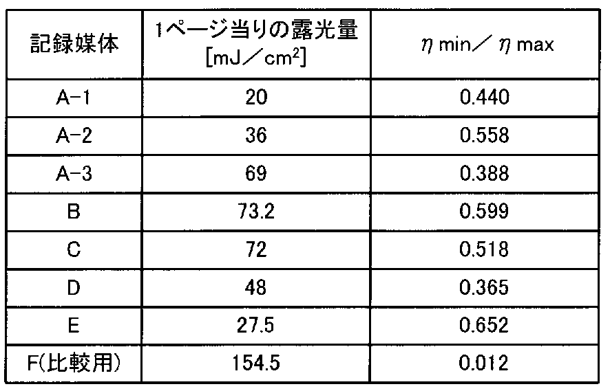
図4~図11及び表1から明らかなように、本実施例で得た記録媒体A~Eのηmin/ηmaxはいずれも0.3以上であり、上記48多重記録においては、スケジューリングが本質的に必要ないことが分かる。一方、比較例で得た記録媒体Fにおいては、ηmin/ηmaxは0.012という低い値であり、上記48多重記録においては、スケジューリングが必要であることが分かる。
なお、図4~図6及び表1のA1-1、A-2、A-3の結果から分かるように、記録媒体Aに対する記録信号光及び記録参照光の照射エネルギーを変化させた場合においても、ηmin/ηmaxは0.3以上を保っており、記録媒体Aに対する記録信号光及び記録参照光の照射エネルギーが変化した場合においても、スケジューリングの有無に影響を与えないことが判明した。
以上、本発明を上記具体例に基づいて詳細に説明したが、本発明は上記具体例に限定されるものではなく、本発明の範疇を逸脱しない限りにおいてあらゆる変形や変更が可能である。
(国等の委託研究の成果に係る記載事項)
平成22年度、独立行政法人科学技術振興機構、産学イノベーション加速事業「戦略的イノベーション創出推進」、「テラバイト時代に向けたポリマーによる三次元ベクトル波メモリ技術の実用化研究」に係る委託研究、産業技術力強化法第19条の適用を受ける特許出願。
(国等の委託研究の成果に係る記載事項)
平成22年度、独立行政法人科学技術振興機構、産学イノベーション加速事業「戦略的イノベーション創出推進」、「テラバイト時代に向けたポリマーによる三次元ベクトル波メモリ技術の実用化研究」に係る委託研究、産業技術力強化法第19条の適用を受ける特許出願。
10 ベクトル波記録媒体
11 透明基板
12 情報記録層
21 記録信号光
22 記録参照光
23 再生参照光
11 透明基板
12 情報記録層
21 記録信号光
22 記録参照光
23 再生参照光
Claims (12)
- 光誘起複屈折材料からなる情報記録層を有し、第1の偏光状態の記録信号光及び前記第1の偏光状態と異なる第2の偏光状態の記録参照光を照射し、前記情報記録層に対してホログラフィックにベクトル波多重記録を行なうベクトル波記録媒体であって、
前記記録信号光及び前記記録参照光の照射エネルギーを一定として、前記情報記録層に対して前記ベクトル波多重記録をホログラフィックに実施した後の、前記情報記録層における各記録情報に相当する各回折格子からの再生信号光の回折効率の最大値をηmax、最小値をηminとしたとき、
ηmin/ηmax≧0.1
を満たすことを特徴とする、ベクトル波記録媒体。 - 前記光誘起複屈折材料は、光ラジカル発生剤及びポリマーマトリックスを含む材料であることを特徴とする、請求項1に記載のベクトル波記録媒体。
- 前記光ラジカル発生剤は、分子内開裂型光ラジカル発生剤であることを特徴とする、請求項2に記載のベクトル波記録媒体。
- 前記分子内開裂型光ラジカル発生剤は、α-アミノアセトフェノン化合物又はオキシムエステル化合物であることを特徴とする、請求項3に記載のベクトル波記録媒体。
- 前記第1の偏光状態は、p偏光及びs偏光の一方であり、前記第2の偏光状態は、p偏光及びs偏光の他方であることを特徴とする、請求項1~4のいずれか一に記載のベクトル波記録媒体。
- 前記情報記録層における前記ベクトル波多重記録は、前記情報記録層のブラック条件を変化させて行うことを特徴とする、請求項1~5のいずれか一に記載のベクトル波記録媒体。
- 光誘起複屈折材料からなる情報記録層を有するベクトル波記録媒体に対して、第1の偏光状態の記録信号光及び前記第1の偏光状態と異なる第2の偏光状態の記録参照光を、前記記録信号光及び前記記録参照光の照射エネルギーを一定として照射し、前記情報記録層に対してホログラフィックにベクトル波多重記録を行なうステップと、
前記ベクトル波記録媒体に対して前記第2の偏光状態の再生参照光を照射し、前記情報記録層における各記録情報に相当する各回折格子からの再生信号光を得るステップとを具え、
再生信号光の回折効率の最大値をηmax、最小値をηminとしたとき、
ηmin/ηmax≧0.1
を満たすことを特徴とする、ベクトル波記録媒体の多重記録再生方法。 - 前記光誘起複屈折材料は、光ラジカル発生剤及びポリマーマトリックスを含む材料であることを特徴とする、請求項7に記載のベクトル波記録媒体の多重記録再生方法。
- 前記光ラジカル発生剤は、分子内開裂型光ラジカル発生剤であることを特徴とする、請求項8に記載のベクトル波記録媒体の多重記録再生方法。
- 前記分子内開裂型光ラジカル発生剤は、α-アミノアセトフェノン化合物又はオキシムエステル化合物であることを特徴とする、請求項9に記載のベクトル波記録媒体の多重記録再生方法。
- 前記第1の偏光状態は、p偏光及びs偏光の一方であり、前記第2の偏光状態は、p偏光及びs偏光の他方であることを特徴とする、請求項7~10のいずれか一に記載のベクトル波記録媒体の記録再生方法。
- 前記情報記録層における前記ベクトル波多重記録は、前記情報記録層のブラック条件を変化させて行うことを特徴とする、請求項7~11のいずれか一に記載のベクトル波記録媒体。
Priority Applications (1)
| Application Number | Priority Date | Filing Date | Title |
|---|---|---|---|
| US13/984,952 US20130321783A1 (en) | 2011-03-16 | 2012-03-14 | Vector wave recording medium, and multiple recording and reproducing method |
Applications Claiming Priority (2)
| Application Number | Priority Date | Filing Date | Title |
|---|---|---|---|
| JP2011-057810 | 2011-03-16 | ||
| JP2011057810A JP5747345B2 (ja) | 2011-03-16 | 2011-03-16 | ベクトル波記録媒体、及び多重記録再生方法 |
Publications (1)
| Publication Number | Publication Date |
|---|---|
| WO2012124317A1 true WO2012124317A1 (ja) | 2012-09-20 |
Family
ID=46830408
Family Applications (1)
| Application Number | Title | Priority Date | Filing Date |
|---|---|---|---|
| PCT/JP2012/001769 Ceased WO2012124317A1 (ja) | 2011-03-16 | 2012-03-14 | ベクトル波記録媒体、及び多重記録再生方法 |
Country Status (4)
| Country | Link |
|---|---|
| US (1) | US20130321783A1 (ja) |
| JP (1) | JP5747345B2 (ja) |
| TW (1) | TW201250678A (ja) |
| WO (1) | WO2012124317A1 (ja) |
Cited By (1)
| Publication number | Priority date | Publication date | Assignee | Title |
|---|---|---|---|---|
| WO2024198745A1 (zh) * | 2023-03-30 | 2024-10-03 | 华为技术有限公司 | 全息光聚合材料、全息感光膜、全息光学元件、显示设备 |
Families Citing this family (6)
| Publication number | Priority date | Publication date | Assignee | Title |
|---|---|---|---|---|
| WO2014057688A1 (ja) * | 2012-10-12 | 2014-04-17 | 新日鉄住金化学株式会社 | 光誘起複屈折材料、それを用いた光記録媒体および光記録方法 |
| EP3168054B1 (en) * | 2015-11-16 | 2019-03-06 | King Abdulaziz City for Science and Technology | An apparatus light pen and its use |
| CN107353421B (zh) * | 2017-06-08 | 2020-09-04 | 太仓市智威智能科技有限公司 | 一种抗刮痕全息存储卡的制备方法 |
| CN107341535B (zh) * | 2017-06-08 | 2020-11-03 | 太仓市智威智能科技有限公司 | 一种抗刮痕全息存储卡 |
| CN109459870B (zh) * | 2018-07-04 | 2020-04-24 | 北京理工大学 | 基于双折射介质超颖表面的多通道矢量全息偏振复用方法 |
| US11341620B2 (en) * | 2020-05-05 | 2022-05-24 | Microsoft Technology Licensing, Llc | Background correction for birefringence measurements |
Citations (3)
| Publication number | Priority date | Publication date | Assignee | Title |
|---|---|---|---|---|
| JPH10340479A (ja) * | 1997-04-11 | 1998-12-22 | Fuji Xerox Co Ltd | 光記録媒体、光記録方法、光記録装置、光読取方法、光読取装置、光検索方法、光検索装置 |
| JP2007047302A (ja) * | 2005-08-08 | 2007-02-22 | Toshiba Corp | ホログラム記録媒体 |
| JP2010524037A (ja) * | 2007-04-11 | 2010-07-15 | バイエル・マテリアルサイエンス・アクチェンゲゼルシャフト | ホログラフィ用途用の有利な記録媒体 |
Family Cites Families (3)
| Publication number | Priority date | Publication date | Assignee | Title |
|---|---|---|---|---|
| US8120826B2 (en) * | 2005-01-06 | 2012-02-21 | National University Corporation Kobe University | Optical information recorder (reflection holographic memory device) |
| KR101526618B1 (ko) * | 2007-05-11 | 2015-06-05 | 바스프 에스이 | 옥심 에스테르 광개시제 |
| JP2012048790A (ja) * | 2010-08-27 | 2012-03-08 | Nippon Steel Chem Co Ltd | 光記録方法、及び光再生方法 |
-
2011
- 2011-03-16 JP JP2011057810A patent/JP5747345B2/ja not_active Expired - Fee Related
-
2012
- 2012-03-14 US US13/984,952 patent/US20130321783A1/en not_active Abandoned
- 2012-03-14 WO PCT/JP2012/001769 patent/WO2012124317A1/ja not_active Ceased
- 2012-03-16 TW TW101109114A patent/TW201250678A/zh unknown
Patent Citations (3)
| Publication number | Priority date | Publication date | Assignee | Title |
|---|---|---|---|---|
| JPH10340479A (ja) * | 1997-04-11 | 1998-12-22 | Fuji Xerox Co Ltd | 光記録媒体、光記録方法、光記録装置、光読取方法、光読取装置、光検索方法、光検索装置 |
| JP2007047302A (ja) * | 2005-08-08 | 2007-02-22 | Toshiba Corp | ホログラム記録媒体 |
| JP2010524037A (ja) * | 2007-04-11 | 2010-07-15 | バイエル・マテリアルサイエンス・アクチェンゲゼルシャフト | ホログラフィ用途用の有利な記録媒体 |
Cited By (1)
| Publication number | Priority date | Publication date | Assignee | Title |
|---|---|---|---|---|
| WO2024198745A1 (zh) * | 2023-03-30 | 2024-10-03 | 华为技术有限公司 | 全息光聚合材料、全息感光膜、全息光学元件、显示设备 |
Also Published As
| Publication number | Publication date |
|---|---|
| TW201250678A (en) | 2012-12-16 |
| JP5747345B2 (ja) | 2015-07-15 |
| JP2012194335A (ja) | 2012-10-11 |
| US20130321783A1 (en) | 2013-12-05 |
Similar Documents
| Publication | Publication Date | Title |
|---|---|---|
| JP5747345B2 (ja) | ベクトル波記録媒体、及び多重記録再生方法 | |
| US7209270B2 (en) | Method and apparatus for phase correlation holographic drive | |
| US20060280096A1 (en) | Erasing holographic media | |
| CN101783148B (zh) | 数据存储装置和方法 | |
| US20060275670A1 (en) | Post-curing of holographic media | |
| US20060281021A1 (en) | Illuminative treatment of holographic media | |
| KR20100074080A (ko) | 데이터 저장 매체에 사용되는 방법 및 시스템 | |
| JP3906831B2 (ja) | ホログラム記録方法 | |
| US7122290B2 (en) | Holographic storage medium | |
| JP5415540B2 (ja) | 角度制御方法 | |
| JP4792526B2 (ja) | ホログラフィック記録媒体用組成物 | |
| Wilson et al. | Realization of high-performance holographic data storage: the InPhase Technologies demonstration platform | |
| CN100508036C (zh) | 全息记录介质和全息记录再现设备 | |
| WO2011039968A1 (ja) | 記録装置、記録方法、光記録媒体 | |
| Wang et al. | Photopolymer media for holographic storage at~ 405 nm | |
| TWI555017B (zh) | Optical recording method and optical regeneration method | |
| CN103123791A (zh) | 信息记录装置、信息再现装置和记录介质 | |
| JP2005078691A (ja) | ホログラフィック記録媒体 | |
| JP6308501B2 (ja) | 光誘起複屈折材料、それを用いた光記録媒体および光記録方法 | |
| JP2001344800A (ja) | 光ヘッド装置 | |
| JP2002298378A (ja) | 光記録方法及び光記録装置 | |
| RU2010139441A (ru) | Носитель записи информации, записывающее устройство, устройство воспроизведения и способ воспроизведения | |
| Fukuda et al. | An investigation on polarization-sensitive materials | |
| JP2007207387A (ja) | 光再生方法及び光再生装置 | |
| WO2012160733A1 (ja) | 光情報記録再生装置および光情報記録再生方法 |
Legal Events
| Date | Code | Title | Description |
|---|---|---|---|
| 121 | Ep: the epo has been informed by wipo that ep was designated in this application |
Ref document number: 12757376 Country of ref document: EP Kind code of ref document: A1 |
|
| WWE | Wipo information: entry into national phase |
Ref document number: 13984952 Country of ref document: US |
|
| NENP | Non-entry into the national phase |
Ref country code: DE |
|
| 122 | Ep: pct application non-entry in european phase |
Ref document number: 12757376 Country of ref document: EP Kind code of ref document: A1 |