WO2012121383A1 - 真空ポンプ用電源装置 - Google Patents
真空ポンプ用電源装置 Download PDFInfo
- Publication number
- WO2012121383A1 WO2012121383A1 PCT/JP2012/056162 JP2012056162W WO2012121383A1 WO 2012121383 A1 WO2012121383 A1 WO 2012121383A1 JP 2012056162 W JP2012056162 W JP 2012056162W WO 2012121383 A1 WO2012121383 A1 WO 2012121383A1
- Authority
- WO
- WIPO (PCT)
- Prior art keywords
- temperature
- power supply
- valve
- supply device
- condensation
- Prior art date
- Legal status (The legal status is an assumption and is not a legal conclusion. Google has not performed a legal analysis and makes no representation as to the accuracy of the status listed.)
- Ceased
Links
Images


Classifications
-
- F—MECHANICAL ENGINEERING; LIGHTING; HEATING; WEAPONS; BLASTING
- F04—POSITIVE - DISPLACEMENT MACHINES FOR LIQUIDS; PUMPS FOR LIQUIDS OR ELASTIC FLUIDS
- F04B—POSITIVE-DISPLACEMENT MACHINES FOR LIQUIDS; PUMPS
- F04B37/00—Pumps having pertinent characteristics not provided for in, or of interest apart from, groups F04B25/00 - F04B35/00
- F04B37/06—Pumps having pertinent characteristics not provided for in, or of interest apart from, groups F04B25/00 - F04B35/00 for evacuating by thermal means
- F04B37/08—Pumps having pertinent characteristics not provided for in, or of interest apart from, groups F04B25/00 - F04B35/00 for evacuating by thermal means by condensing or freezing, e.g. cryogenic pumps
-
- F—MECHANICAL ENGINEERING; LIGHTING; HEATING; WEAPONS; BLASTING
- F04—POSITIVE - DISPLACEMENT MACHINES FOR LIQUIDS; PUMPS FOR LIQUIDS OR ELASTIC FLUIDS
- F04D—NON-POSITIVE-DISPLACEMENT PUMPS
- F04D19/00—Axial-flow pumps
- F04D19/02—Multi-stage pumps
- F04D19/04—Multi-stage pumps specially adapted to the production of a high vacuum, e.g. molecular pumps
- F04D19/042—Turbomolecular vacuum pumps
-
- F—MECHANICAL ENGINEERING; LIGHTING; HEATING; WEAPONS; BLASTING
- F04—POSITIVE - DISPLACEMENT MACHINES FOR LIQUIDS; PUMPS FOR LIQUIDS OR ELASTIC FLUIDS
- F04D—NON-POSITIVE-DISPLACEMENT PUMPS
- F04D29/00—Details, component parts, or accessories
- F04D29/58—Cooling; Heating; Diminishing heat transfer
- F04D29/582—Cooling; Heating; Diminishing heat transfer specially adapted for elastic fluid pumps
- F04D29/584—Cooling; Heating; Diminishing heat transfer specially adapted for elastic fluid pumps cooling or heating the machine
Definitions
- the present invention relates to a power supply device for a vacuum pump having a cooling mechanism using a refrigerant.
- turbo molecular pump As one of vacuum pumps used in semiconductor devices.
- a turbo molecular pump is often used after being cooled with water. Therefore, the power supply device integrated with the turbo molecular pump or the power supply device arranged in the vicinity of the pump is often water-cooled together with the pump. Since there is a problem that condensation occurs when the power supply is water-cooled, a configuration in which a sensor for detecting condensation is provided in the power supply is known (see Patent Document 1).
- the power supply device has a dew condensation sensor and a cooling water valve that turns on and off the flow of cooling water into the power supply device, and reports the dew condensation detection to the user when dew condensation is detected.
- a dew condensation sensor and a cooling water valve that turns on and off the flow of cooling water into the power supply device, and reports the dew condensation detection to the user when dew condensation is detected.
- the vacuum pump power supply device includes a cooling pipe for circulating the refrigerant, a temperature sensor for detecting the temperature of the cooling pipe, and a valve for adjusting the circulation amount of the refrigerant in the cooling pipe. And a valve control unit that controls opening and closing of the valve so as to keep the temperature detected by the temperature sensor at a predetermined temperature at which condensation does not occur.
- the valve control unit it is preferable to control the valve so that the valve is opened when the temperature detected by the temperature sensor exceeds the refrigerant management upper limit temperature.
- the power supply device for the vacuum pump further includes a non-feed time calculation unit that calculates a non-feed time during which the feed is interrupted.
- the valve control unit preferably performs control so that the valve is closed until a predetermined time elapses after power supply is started.
- the vacuum pump power supply device according to the first aspect further includes a storage control unit that stores the temperature detected by the temperature sensor in the storage unit when power feeding is started.
- the vacuum pump power supply device includes a cooling pipe for circulating the refrigerant, a temperature sensor for detecting the temperature of the cooling pipe, and a valve for adjusting the circulation amount of the refrigerant in the cooling pipe.
- a condensation sensor that detects internal condensation, and after the condensation is detected by the condensation sensor, the valve is closed until the temperature detected by the temperature sensor exceeds a predetermined threshold, and the condensation sensor detects the condensation. And a controller that controls to stop the operation of the vacuum pump if the temperature detected by the temperature sensor exceeds a predetermined threshold value.
- the present invention it is possible to prevent the pump operation from stopping due to an increase in humidity due to the release of moisture absorption while preventing the occurrence of condensation inside the power supply device.
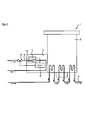
- FIG. 1 is a diagram showing a configuration of a turbo molecular pump 1 having a power supply device 3 according to a first embodiment of the present invention.
- the turbo molecular pump 1 includes a pump body 2 and a power supply device 3.
- the pump main body 2 and the power supply device 3 are physically coupled and integrated, but the pump main body 2 and the power supply device 3 are provided separately, and they are connected to each other by a power cable.
- the present invention can also be applied to turbomolecular pumps connected by
- the pump body 2 includes a rotor (not shown) on which rotor blades are formed, a motor that rotationally drives the rotor, and a magnetic bearing that supports the rotor by magnetically levitating the rotor.
- the pump body 2 includes a heating device (not shown) using a heater and a cooling water channel 4.
- the cooling water channel 4 is a water channel for flowing cooling water inside the pump body.
- the temperature of the pump body 2 is maintained at a high temperature (for example, 50 to 70 ° C.) by the heating by the heating device and the cooling by the cooling water.
- the motor and the magnetic bearing are cooled by the cooling water flowing through the cooling water passage 4.
- the power supply device 3 performs drive control of a motor and a magnetic bearing included in the pump body 2.
- the power supply device 3 includes a cooling pipe 5, a cooling water valve 6, a temperature sensor 12, and a CPU (central processing unit) 8.
- the cooling pipe 5 is provided for cooling the power supply device by circulating cooling water inside the power supply device.
- the cooling pipe 5 is composed of a pipe, a cooling block, and the like, and further, cooling fins are provided on the pipe and the cooling block.
- the cooling water is used as the refrigerant, but various refrigerants can be used without being limited to the cooling water.
- the cooling water valve 6 is an electromagnetic valve for controlling the flow rate of the cooling water flowing through the cooling pipe 5. When the cooling water valve 6 is opened, the cooling water flows into the power supply device 3 through the cooling pipe 5, and when the cooling water valve 6 is closed, the circulation of the cooling water into the power supply device 3 is stopped.
- the temperature sensor 12 is arranged in the cooling pipe 5 through which cooling water flows, and measures the temperature of the cooling pipe. When measuring the temperature of the cooling block or the like, it is desirable to measure the temperature near the pipe.
- a signal related to the temperature detected by the temperature sensor 12 is input to the CPU 8.
- the CPU 8 controls the opening / closing of the cooling water valve 6 based on the signal output from the temperature sensor 12.
- the power supply device 3 in the present embodiment is not provided with a dew condensation sensor, or the dew condensation detection sensitivity is always or temporarily set.
- a relaxed dew condensation sensor is provided.
- the dew condensation sensor detects dew condensation only when the specified humidity is exceeded. By doing so, the dew condensation detection sensitivity of the dew condensation sensor can be relaxed.
- the time from the start of the power supply device 3 to the completion of the release of moisture absorption is specified in advance, and the condensation detection sensitivity of the condensation sensor is relaxed only during the specified time. It is good.
- no dew condensation sensor is provided, or the dew condensation detection sensitivity of dew condensation sensor is constantly or temporarily alleviated, so that the following dew condensation is prevented. Temperature control is performed.
- the cooling water temperature is as high as possible because condensation does not occur.
- the occurrence of dew condensation is prevented by keeping the inside of the power supply device 3 as high as possible within a range in which the excessive temperature rise in the power supply device 3 does not occur.
- an allowable upper limit temperature (refrigerant management upper limit temperature) Tmax is set in order to prevent the temperature inside the power supply device from becoming an excessively high temperature state. Therefore, in the present embodiment, as shown in FIG. 1, the temperature sensor 12 is arranged in the cooling pipe, the temperature T of the cooling pipe is measured, and the temperature in the vicinity of the cooling pipe is maintained near the allowable upper limit temperature Tmax. The opening / closing of the cooling water valve 6 is controlled. Specifically, if the detected temperature detected by the temperature sensor 12 exceeds the allowable upper limit temperature Tmax, the cooling water valve 6 is opened to flow the cooling water, and if the detected temperature does not exceed the allowable upper limit temperature Tmax.
- the allowable upper limit temperature Tmax depends on the temperature upper limit value of the circuit components constituting the power supply device 3, and is determined in advance based on experiments, theoretical calculations, simulations, or the like.
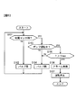
- the opening / closing control of the cooling water valve 6 included in the power supply device 3 according to the first embodiment will be described with reference to the flowchart shown in FIG.
- the CPU 8 executes processing represented by the flowchart shown in FIG. 2 according to a program that starts when the power supply 3 is turned on.
- step S301 the CPU 8 determines whether or not the user has turned off the power supply 3. If the determination is affirmative, this process ends. In the negative determination, in step S302, the CPU 8 determines whether or not the temperature T of the cooling pipe exceeds the allowable upper limit temperature Tmax. When an affirmative determination is made in step S302, in step S303, the CPU 8 opens the cooling water valve 6 and cools the power supply device 3 with the cooling water. If the process of step S303 is completed, the process returns to step S301.
- step S304 the CPU 8 closes the cooling water valve 6, and the process returns to step S301.
- the fact that the temperature T of the cooling pipe is maintained in the vicinity of the allowable upper limit temperature Tmax means that the cooling state is substantially the same as when the cooling water having the allowable upper limit temperature Tmax flows through the cooling pipe 5. That is, the internal temperature of the power supply device 3 is kept as high as possible in the above-described temperature management, and condensation is unlikely to occur. Furthermore, the condensation sensor is not provided, or the condensation detection sensitivity of the condensation sensor is alleviated constantly or temporarily, so that the condensation sensor operates due to the release of moisture that has been absorbed, and the pump operation is stopped. There is no inconvenience.
- the CPU 8 When the temperature detected by the temperature sensor 12, that is, the temperature T of the cooling pipe exceeds the allowable upper limit temperature Tmax, the CPU 8 It is opened and cooling water is distributed. In this case, the temperature T of the cooling pipe should be lowered, but it is conceivable that the temperature T of the cooling pipe rises to a temperature at which the safety of the pump operation cannot be ensured due to a decrease in the flow rate of the cooling water or water breakage. Therefore, a temperature slightly higher than the allowable upper limit temperature Tmax is set as the pump operation stop temperature, and when the temperature detected by the temperature sensor 12 exceeds the pump operation stop temperature, the CPU 8 stops the pump operation to ensure safety. It may be done.
- the initialization processing of the CPU 8 is performed immediately after the power supply of the power supply device 3 is started.
- the CPU 8 obtains the cooling pipe temperature Ts immediately after the start of power supply from the temperature sensor 12 during the initialization process of the CPU 8 and performs storage control so as to be stored in the internal memory of the CPU 8. Thereafter, the CPU 8 opens the cooling water valve 6 and causes the cooling water to flow through the cooling pipe 5.
- the cooling pipe can be considered to have a temperature substantially equal to the ambient temperature around the turbo molecular pump 1. For example, when the ambient temperature is 25 ° C., the temperature of the cooling pipe immediately after the start of power supply is 25 ° C. The temperature of the cooling pipe measured by the temperature sensor 12 is 25 ° C., which is the same as the ambient temperature.
- the temperature of the cooling pipe becomes a value close to the cooling water temperature. That is, when the ambient temperature is 25 ° C., the temperature of the cooling pipe measured immediately after the start of power supply is about 25 ° C., which is substantially the same temperature as the ambient temperature. The temperature decreases with the passage of time and eventually reaches a temperature in the vicinity of 15 ° C., which is the cooling water temperature. If the cooling water temperature is extremely lower than the ambient temperature of the power supply device 3, it is considered that condensation is likely to occur.
- the CPU 8 controls the cooling water valve 6 so that the difference ⁇ T is maintained in the vicinity of the predetermined temperature difference ⁇ T0. For example, the CPU 8 closes the cooling water valve 6 if the difference ⁇ T is not less than the predetermined temperature difference ⁇ T0, and opens the cooling water valve 6 if the difference ⁇ T is less than the predetermined temperature difference ⁇ T0.
- the predetermined temperature difference ⁇ T0 is a threshold value for preventing the occurrence of condensation, and, like the allowable upper limit temperature Tmax in the first embodiment, is measured in advance by theoretical calculation, simulation, or experiment. If you ask for it.
- the opening / closing control of the cooling water valve 6 included in the power supply device 3 according to the modification of the first embodiment will be described with reference to the flowchart shown in FIG.
- the CPU 8 executes the process represented by the flowchart shown in FIG. 3 according to a program that starts when the power supply 3 is turned on.
- step S401 the CPU 8 acquires the cooling pipe temperature Ts immediately after the power source 3 is turned on from the temperature sensor 12, and stores it in the internal memory of the CPU 8.
- step S ⁇ b> 402 the CPU 8 determines whether the user has turned off the power supply 3. If the determination is affirmative, this process ends. In a negative determination, in step S403, the latest cooling pipe temperature Tc is acquired from the temperature sensor 12, and the difference ⁇ T is acquired by calculation.
- step S404 the CPU 8 determines whether or not the difference ⁇ T is less than a predetermined temperature difference ⁇ T0. When an affirmative determination is made in step S404, in step S405, the CPU 8 opens the cooling water valve 6 and cools the power supply device 3 with the cooling water. If the process of step S405 is completed, the process returns to step S402.
- step S404 When a negative determination is made in step S404, in step S406, the CPU 8 closes the cooling water valve 6, and the process returns to step S402.
- the CPU 8 when the power supply device 3 is activated, the CPU 8 acquires the temperature Ts detected by the temperature sensor 12 during the initialization process of the CPU 8 and stores it in the internal memory of the CPU 8. Therefore, the CPU 8 can acquire the difference ⁇ T based on the ambient temperature Ts around the turbo molecular pump 1.
- the internal temperature of the power supply device 3 is maintained at a temperature at which dew condensation does not occur, and the temperature in the power supply device is compared with the control method in the first embodiment. Can be kept at a low temperature.
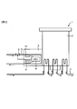
- FIG. 4 is a diagram showing a configuration of the turbo molecular pump 1 having the power supply device 3 according to the second embodiment of the present invention.
- the dew condensation sensor 7 is provided in the power supply device 3 shown in FIG.
- the dew condensation sensor 7 is a sensor for detecting dew condensation inside the power supply device.
- the dew condensation sensor 7 outputs a dew condensation detection signal to the CPU 8 when dew condensation is detected, and outputs a dew condensation non-detection signal to the CPU 8 when dew condensation is not detected.
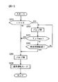
- the opening / closing control of the cooling water valve 6 included in the power supply device 3 according to the second embodiment will be described with reference to the flowchart shown in FIG.
- the CPU 8 executes the process represented by the flowchart shown in FIG. 5 according to a program that starts when the power supply 3 is turned on.
- step S101 the CPU 8 determines whether or not the dew condensation sensor 7 has been turned on by detecting dew condensation based on the signal output from the dew condensation sensor 7.
- NO is determined in step S101 and the process proceeds to step S102.
- step S102 the CPU 8 opens the cooling water valve 6 and cools the power supply device 3 with the cooling water. If the process of step S102 is completed, the process returns to step S101.
- step S101 determines with YES by step S101, and progresses to step S103.
- step S103 the CPU 8 determines whether or not the pump is operating. If the pump is operating, the process proceeds to step S105, and if the pump is stopped, the process proceeds to step S104. If the process proceeds to step S104, the CPU 8 closes the cooling water valve 6 in step S104 and returns to step S101.
- step S105 the CPU 8 prevents the temperature T of the cooling pipe in the power supply device from causing the temperature in the power supply device to be excessively high. It is determined whether or not the allowable upper limit temperature Tmax is exceeded. Note that the allowable upper limit temperature Tmax of the internal temperature of the power supply device 3 may be determined in advance, for example, by measuring by theoretical calculation, simulation, experiment, or the like, as described in the description of the first embodiment. If it is determined in step S105 that the temperature T exceeds the allowable upper limit temperature Tmax, the process proceeds to step S106. In step S106, the CPU 8 causes an alarm device (not shown) to generate an alarm notifying the occurrence of condensation.
- step S107 the CPU 8 stops the operation of the pump, and the process represented by the flowchart shown in FIG. 5 ends.
- the process proceeds to step S104.
- step S104 the CPU 8 closes the cooling water valve 6, and then returns to step S101.
- the temperature T of the cooling pipe in the power supply device prevents the temperature in the power supply device from being overheated. If the temperature is equal to or lower than the allowable upper limit temperature Tmax, the pump operation is continued with the cooling water valve 6 closed. When the temperature T exceeds the allowable upper limit temperature Tmax, a protection operation that stops the pump operation is performed. Thus, even when the dew condensation sensor 7 is turned on, the pump is not stopped immediately, but the flow of the cooling water is stopped and the dew condensation sensor 7 is turned off. Therefore, when the moisture absorbed is released and the dew condensation sensor 7 is turned on, the temperature in the power supply device is increased by stopping the cooling water. When the dew condensation detection state caused by the release of moisture absorbed due to the temperature rise in the power supply device is resolved, the dew condensation sensor 7 is turned off.
- the temperature in the power supply device is kept high by the processing in steps S104 and S105. However, condensation continues even if the operation at a high temperature is continued. It may not be resolved. If the condensation does not disappear even if the operation in the high temperature state is continued, the temperature T of the cooling pipe in the power supply device may exceed the allowable upper limit temperature Tmax. When the temperature T exceeds the allowable upper limit temperature Tmax, the cooling water valve 6 may be opened in order to cool the inside of the power supply device, but it is not preferable that the pump operation is continued in a state where condensation does not disappear. There is sex. Therefore, in the power supply device 3 in the present embodiment, as described above, the pump can be safely stopped when the temperature T exceeds the allowable upper limit temperature Tmax.
- FIG. 6 is a diagram showing a configuration of the turbo molecular pump 1 having the power supply device 3 according to the third embodiment of the present invention.
- the RTC 9 is a counter obtained by the IC, and is a counter that keeps incrementing the count value regardless of whether AC power is supplied or not for battery operation.
- both a CPU internal counter that integrates the energization time of the power supply device 3 inside the CPU 8 and a counter that continues to advance regardless of whether AC power is supplied, such as the RTC 9 or the like.
- the no-power supply time is a time during which the power supply to the power supply device 3 is cut off, and is calculated based on the difference between the count value Cr by the RTC 9 and the count value Cc by the CPU internal counter.
- FIG. 7 is a flowchart showing processing executed at the start of power supply when the power supply 3 is turned on.
- the process shown in FIG. 7 is a process executed before the opening / closing control of the cooling water valve 6 included in the power supply device 3 in the first embodiment shown in FIG. 2, and the CPU 8 turns on the power supply 3.
- the process represented by the flowchart shown in FIG. 7 is executed according to the program that starts when the state is reached.
- step S201 the CPU 8 determines whether or not the non-feed time t exceeds a predetermined threshold t0.
- a non-power-feed time is set such that moisture absorption that affects the operation of the condensation sensor 7 can occur.
- the threshold t0 is determined in advance based on experiments, theoretical calculations, simulations, or the like. For example, a value of about 12 hours is set as the threshold value t0. If the CPU 8 determines in step S201 that t> t0, the CPU 8 closes the cooling water valve 6 in step S202. As a result, the temperature inside the power supply device rises, and an aging process for releasing moisture absorbed is started.
- step S201 determines that t ⁇ t0 in step S201, that is, if the influence of moisture absorption on the operation of the dew condensation sensor 7 is small.
- step S205 the CPU 8 opens the cooling water valve 6.
- step S206 the operation mode is shifted to the normal operation mode.
- the normal operation mode is a mode in which the valve control described in the first embodiment is performed.
- step S203 the CPU 8 determines whether or not the temperature T of the cooling pipe inside the power supply device 3, that is, the detected temperature detected by the temperature sensor 12, exceeds the allowable upper limit temperature Tmax. If it is determined in step S203 that the temperature T has exceeded the allowable upper limit temperature Tmax, the aging process ends, and the process proceeds to step S205 described above.
- step S203 determines whether or not a predetermined aging time has elapsed.
- the predetermined aging time is a time sufficient for eliminating moisture absorption.
- a predetermined time is preset as the predetermined aging time based on experiments, theoretical calculations, simulations, or the like. Due to the aging process, the temperature inside the power supply device becomes high, and even if moisture absorption occurs before the aging process, the moisture that has been absorbed evaporates during the aging process and is released to the outside of the power supply device 3. And will be diffused.
- step S203 The time from when the power supply 3 is turned on until when the temperature T of the cooling pipe exceeds the allowable upper limit temperature Tmax is set in advance based on experiments, theoretical calculations, simulations, or the like. It may be taken into account when it is done. In this case, the determination process in step S203 is not necessary in the flowchart shown in FIG.
- moisture absorption to the circuit board and circuit elements inside the power supply device may proceed depending on the humidity state of the surrounding environment.
- moisture that has been absorbed appears as water vapor inside the power supply device due to a rise in the temperature inside the power supply device.
- condensation may be easily detected by the condensation sensor.
- turbo molecular pump power supply device 3 has been described as an example.
- the present invention is not limited to the turbo molecular pump, but may be applied to various vacuum pumps such as a molecular drag pump. The invention can be applied.
Landscapes
- Engineering & Computer Science (AREA)
- Mechanical Engineering (AREA)
- General Engineering & Computer Science (AREA)
- Physics & Mathematics (AREA)
- Thermal Sciences (AREA)
- Non-Positive Displacement Air Blowers (AREA)
- Compressors, Vaccum Pumps And Other Relevant Systems (AREA)
- Control Of Positive-Displacement Pumps (AREA)
Abstract
真空ポンプ用電源装置は、冷媒を流通させるための冷却配管と、冷却配管の温度を検出する温度センサと、冷却配管における冷媒の流通量を調整するバルブと、温度センサによって検出された温度を、結露が発生しない所定温度に保つように、バルブの開閉を制御するバルブ制御部と、を備える。
Description
本発明は、冷媒による冷却機構を有する真空ポンプ用電源装置に関する。
半導体装置に用いられる真空ポンプの一つとしてターボ分子ポンプがある。ターボ分子ポンプは一般に水冷されて使用されることが多い。そのため、ターボ分子ポンプと一体化された電源装置、あるいはポンプ近傍に配置された電源装置は、ポンプとともに水冷されることが多い。電源装置を水冷する場合、結露が発生するという問題があるため、電源装置内に結露を検知するセンサを設ける構成が知られている(特許文献1参照)。
特許文献1に記載の技術では、電源装置は結露センサと電源装置内部への冷却水の流入をオン・オフする冷却水バルブとを有し、結露検知時にユーザへ結露検知を報告したり、冷却水の流入を遮断したりすることによって結露の進行を防ぎ、結露による電源装置の故障を防ぐようにしている。
しかしながら、電源装置への給電が停止された状態が継続した場合、例えば、電源装置が保管されている場合などにおいて、そのときの周囲環境の湿度状態によっては、電源装置内の基板や回路部品などへの吸湿が進行することがある。そのような状態で電源装置への給電が開始され、ターボ分子ポンプの運転が開始された場合、吸湿されていた水分が電源装置内部温度の上昇により電源装置内に放出されることになる。その結果、電源装置に結露センサが設けられていると、たとえ冷却水が使用されていない場合であっても、このような一時的な湿度上昇により結露センサが結露を検知してしまい、ポンプ運転が停止されてしまうことがある。すなわち、電源装置内部の結露の発生を防止しつつ、吸湿水分の放出による湿度上昇のためにポンプ運転が停止することを防止することができないという問題がある。
本発明の第1の態様によると、真空ポンプ用電源装置は、冷媒を流通させるための冷却配管と、冷却配管の温度を検出する温度センサと、冷却配管における冷媒の流通量を調整するバルブと、温度センサによって検出された温度を、結露が発生しない所定温度に保つように、バルブの開閉を制御するバルブ制御部と、を備える。
本発明の第2の態様によると、第1の態様の真空ポンプ用電源装置において、温度センサによって検出される温度が、所定温度としての冷媒管理上限温度を超過しないとき、バルブ制御部はバルブを閉じるように制御し、温度センサによって検出される温度が冷媒管理上限温度を超過したとき、バルブ制御部はバルブを開くように制御するのが好ましい。
本発明の第3の態様によると、第2の態様の真空ポンプ用電源装置において、給電が遮断されている無給電時間を算出する無給電時間算出部をさらに備え、給電が開始された際、無給電時間が所定閾値を超えている場合には、バルブ制御部は、給電が開始されてから所定時間経過するまでバルブを閉じるように制御するのが好ましい。
本発明の第4の態様によると、第1の態様の真空ポンプ用電源装置において、給電が開始された際、温度センサによって検出された温度を記憶部に記憶させる記憶制御部をさらに備え、記憶部によって記憶された温度と給電開始後の給電中に温度センサによって検出される温度との差が、記憶部によって記憶された温度と所定温度との所定温度差を下回っていないならば、バルブ制御部はバルブを閉じるように制御し、差が所定温度差を下回ったならば、バルブ制御部はバルブを開くように制御するのが好ましい。
本発明の第5の態様によると、真空ポンプ用電源装置は、冷媒を流通させるための冷却配管と、冷却配管の温度を検出する温度センサと、冷却配管における冷媒の流通量を調整するバルブと、内部の結露を検出する結露センサと、結露センサによって結露が検出されてから、温度センサによって検出される温度が所定閾値を超えるまでバルブを閉じるように制御するとともに、結露センサによって結露が検出された後、温度センサによって検出される温度が所定閾値を超過したならば真空ポンプの運転を停止するように制御する制御部と、を備える。
本発明の第2の態様によると、第1の態様の真空ポンプ用電源装置において、温度センサによって検出される温度が、所定温度としての冷媒管理上限温度を超過しないとき、バルブ制御部はバルブを閉じるように制御し、温度センサによって検出される温度が冷媒管理上限温度を超過したとき、バルブ制御部はバルブを開くように制御するのが好ましい。
本発明の第3の態様によると、第2の態様の真空ポンプ用電源装置において、給電が遮断されている無給電時間を算出する無給電時間算出部をさらに備え、給電が開始された際、無給電時間が所定閾値を超えている場合には、バルブ制御部は、給電が開始されてから所定時間経過するまでバルブを閉じるように制御するのが好ましい。
本発明の第4の態様によると、第1の態様の真空ポンプ用電源装置において、給電が開始された際、温度センサによって検出された温度を記憶部に記憶させる記憶制御部をさらに備え、記憶部によって記憶された温度と給電開始後の給電中に温度センサによって検出される温度との差が、記憶部によって記憶された温度と所定温度との所定温度差を下回っていないならば、バルブ制御部はバルブを閉じるように制御し、差が所定温度差を下回ったならば、バルブ制御部はバルブを開くように制御するのが好ましい。
本発明の第5の態様によると、真空ポンプ用電源装置は、冷媒を流通させるための冷却配管と、冷却配管の温度を検出する温度センサと、冷却配管における冷媒の流通量を調整するバルブと、内部の結露を検出する結露センサと、結露センサによって結露が検出されてから、温度センサによって検出される温度が所定閾値を超えるまでバルブを閉じるように制御するとともに、結露センサによって結露が検出された後、温度センサによって検出される温度が所定閾値を超過したならば真空ポンプの運転を停止するように制御する制御部と、を備える。
本発明によれば、電源装置内部の結露の発生を防止しつつ、吸湿水分の放出による湿度上昇のためにポンプ運転が停止することを防止できる。
-第1の実施の形態-
図1は、本発明の第1の実施の形態における電源装置3を有するターボ分子ポンプ1の構成を示す図である。ターボ分子ポンプ1は、ポンプ本体2と電源装置3とを含む。図1に示すターボ分子ポンプ1では、ホンプ本体2と電源装置3とが物理的に結合され一体化されているが、ホンプ本体2と電源装置3とが別々に設けられ、それらが互いに電源ケーブルで接続されているターボ分子ポンプにも本発明は適用できる。
図1は、本発明の第1の実施の形態における電源装置3を有するターボ分子ポンプ1の構成を示す図である。ターボ分子ポンプ1は、ポンプ本体2と電源装置3とを含む。図1に示すターボ分子ポンプ1では、ホンプ本体2と電源装置3とが物理的に結合され一体化されているが、ホンプ本体2と電源装置3とが別々に設けられ、それらが互いに電源ケーブルで接続されているターボ分子ポンプにも本発明は適用できる。
ポンプ本体2は、不図示の、回転翼が形成されたロータと、ロータを回転駆動するモータと、ロータを磁気浮上させることによりロータを支持する磁気軸受とを含んでいる。また、ポンプ本体2は、ヒータを用いた不図示の加熱装置と、冷却水路4とを含む。冷却水路4は、ポンプ本体内部に冷却水を流すための水路である。加熱装置による加熱と、冷却水による冷却とにより、ポンプ本体2の温度は、高温(たとえば、50~70℃)に保持される。また、冷却水路4を通じて流れる冷却水により、モータや磁気軸受が冷却される。
電源装置3は、ポンプ本体2に含まれるモータや磁気軸受の駆動制御を行う。電源装置3は、冷却配管5と、冷却水バルブ6と、温度センサ12と、CPU(中央処理装置)8とを含む。冷却配管5は、電源装置内部に冷却水を流通させて電源装置を冷却するために設けられている。例えば、冷却配管5はパイプや冷却ブロックなどで構成され、さらに、それらのパイプや冷却ブロックには冷却フィンなどが設けられている。なお、本実施の形態としては冷却水を冷媒に用いているが、冷却水に限らず種々の冷媒を用いることができる。
冷却水バルブ6は、冷却配管5を流れる冷却水の流量を制御するための電磁バルブである。冷却水バルブ6を開くと、冷却配管5を通じて冷却水が電源装置3の内部に流れ、冷却水バルブ6を閉じると、電源装置3の内部への冷却水の流通が止まる。
温度センサ12は、冷却水が流れる冷却配管5に配置され、冷却配管の温度を測定する。なお、冷却ブロック等の温度を測定する際には、パイプに近い部位の温度を測定することが望ましい。温度センサ12によって検出された温度に関する信号はCPU8に入力される。CPU8は、温度センサ12から出力される信号に基づいて、冷却水バルブ6の開閉を制御する。
図1の電源装置3には、電源装置内部の結露を検出するためのセンサである結露センサが図示されていない。一時的な湿度上昇によりポンプ運転が停止されてしまうということを防止するため、本実施の形態における電源装置3には、結露センサが設けられていないか、または結露検知感度を常時もしくは一時的に緩和した結露センサが設けられる。結露センサが設けられる場合には、実験、理論計算、あるいはシミュレーション等に基づき、吸湿水分の放出により上昇する湿度が予め特定され、その特定された湿度を超えた場合にのみ結露センサによる結露検出がなされるようにすることで、結露センサの結露検知感度を緩和することができる。実験、理論計算、あるいはシミュレーション等に基づき、電源装置3の起動開始から吸湿水分の放出完了までの時間が予め特定され、その特定された時間においてのみ、結露センサの結露検知感度が緩和されることとしてもよい。本実施の形態における電源装置3においては、結露センサが設けられていないか、または結露センサの結露検知感度が常時もしくは一時的に緩和されるため、以下に示すような、結露発生を防止するための温度制御がなされる。
冷却水の温度が電源装置3の周囲温度よりも極端に低い場合には、冷却配管や、冷却配管によって冷やされたその近傍の部材に結露が発生しやすい。冷却水温度は可能な限り高い方が、結露が発生しないため、好ましい。本実施の形態では、電源装置3内部の過昇温を生じない範囲で、電源装置3内部を可能な限りの高い温度に保つことで、結露の発生を防止する。
冷却配管5を流れる冷却水の温度に関して、電源装置内温度が過昇温状態になるのを防止するため、許容上限温度(冷媒管理上限温度)Tmaxが設定されている。そこで、本実施の形態では、図1に示すように冷却配管に温度センサ12が配置されて冷却配管の温度Tが計測され、その冷却配管近傍の温度が許容上限温度Tmax付近に保たれるように冷却水バルブ6の開閉が制御される。具体的には、温度センサ12によって検出された検出温度が許容上限温度Tmaxを超過したならば冷却水バルブ6を開いて冷却水を流通させ、検出された温度が許容上限温度Tmaxを超過しないならば冷却水バルブ6を閉じて冷却水の供給を停止する。許容上限温度Tmaxは、電源装置3を構成する回路部品等の温度上限値に依存し、実験、理論計算、あるいはシミュレーション等に基づき、予め決定される。
第1の実施の形態における電源装置3が有する冷却水バルブ6の開閉制御について、図2に示すフローチャートを参照して説明する。CPU8は、電源装置3の電源がオン状態になるとスタートするプログラムにしたがって、図2に示すフローチャートによって表される処理を実行する。
ステップS301では、CPU8は、ユーザが電源装置3の電源をオフにしたか否かを判定する。肯定判定の場合、本処理は終了する。否定判定の場合、ステップS302において、CPU8は、冷却配管の温度Tが許容上限温度Tmaxを上回っているか否かを判定する。ステップS302において肯定判定のとき、ステップS303において、CPU8は、冷却水バルブ6を開いて、冷却水による電源装置3の冷却を行う。ステップS303の処理が終了したならば、処理はステップS301へ戻る。
ステップS302において否定判定のとき、ステップS304において、CPU8は冷却水バルブ6を閉じ、処理はステップS301へ戻る。
冷却配管の温度Tが許容上限温度Tmax付近に保たれるということは、冷却配管5に許容上限温度Tmaxの冷却水が流れている場合とほぼ同等の冷却状況となっていることを意味する。すなわち、電源装置3の内部温度が、上述した温度管理上において可能な限りの高い温度に保たれていることになり、結露が発生しにくい。さらに、結露センサを設けていないか、または結露センサの結露検知感度が常時もしくは一時的に緩和されるので、吸湿していた水分の放出により結露センサが動作してポンプ運転が停止されてしまうという不都合が生じることはない。
なお、上述した本実施の形態における冷却水バルブ6の開閉制御においては、温度センサ12による検出温度、すなわち冷却配管の温度Tが許容上限温度Tmaxを超えたときに、CPU8によって冷却水バルブ6が開かれ、冷却水が流通することとしている。その場合、冷却配管の温度Tは低下するはずであるが、冷却水の流量低下や断水が原因で冷却配管の温度Tがポンプ運転の安全が確保できない温度にまで上昇することが考えられる。そのため、許容上限温度Tmaxよりも若干高い温度をポンプ運転停止温度に設定し、温度センサ12による検出温度がポンプ運転停止温度を超えたときに、CPU8がポンプ運転を停止させることで、安全が確保されることとしてもよい。
-第1の実施の形態の変形例-
上述した第1の実施の形態の説明では、温度センサ12によって検出される検出温度Tが許容上限温度Tmax付近に保たれるように、検出温度が許容上限温度を超過しているか下回っているかに応じて、冷却水バルブ6が開閉されるようにした。ここでは、別の制御方法について説明する。なお、電源装置3の構成については第1の実施の形態と同様である。
上述した第1の実施の形態の説明では、温度センサ12によって検出される検出温度Tが許容上限温度Tmax付近に保たれるように、検出温度が許容上限温度を超過しているか下回っているかに応じて、冷却水バルブ6が開閉されるようにした。ここでは、別の制御方法について説明する。なお、電源装置3の構成については第1の実施の形態と同様である。
電源装置3の給電開始直後にCPU8の初期化処理が実施される。CPU8は、給電開始直後の冷却配管温度Tsを、CPU8の初期化処理中に温度センサ12から取得しておき、CPU8の内部メモリに記憶させるように記憶制御する。その後、CPU8は、冷却水バルブ6を開いて冷却配管5に冷却水を流通させる。電源装置3への給電が停止していたときには、冷却配管は、ターボ分子ポンプ1周囲の周囲温度と略等しい温度であると考えることができる。例えば、周囲温度が25℃であった場合には、給電開始直後の冷却配管の温度は25℃となっている。温度センサ12により計測される冷却配管の温度も周囲温度と同様の25℃である。
冷却水バルブ6が開かれて冷却配管5に冷却水が供給されると、冷却配管の温度は冷却水温度に近い値となる。すなわち、周囲温度が上記25℃の場合、給電開始直後に計測される冷却配管の温度は周囲温度とほぼ同じ温度の25℃付近であるが、例えば15℃の冷却水が流通した場合、冷却配管の温度は、時間の経過とともに低下し、やがては冷却水温度である15℃付近の温度となる。もし、冷却水温度が電源装置3の周囲温度よりも極端に低い場合には、結露が発生しやすい状態となると考えられる。
給電開始直後の冷却配管の温度Tsと、その後の冷却水が流通しているときの温度Tcとの差ΔT=Ts-Tcが、大きすぎると結露が発生しやすい。CPU8は、この差ΔTが所定温度差ΔT0付近に保たれるように冷却水バルブ6を制御する。例えば、CPU8は、差ΔTが所定温度差ΔT0を下回っていない場合には冷却水バルブ6を閉じ、差ΔTが所定温度差ΔT0を下回ったならば冷却水バルブ6を開く。なお、所定温度差ΔT0は、結露の発生を防止するための閾値であり、第1の実施の形態における許容上限温度Tmaxと同様に、予め、理論計算、シミュレーション、あるいは実験して実測するなどして求めておけば良い。
第1の実施の形態の変形例における電源装置3が有する冷却水バルブ6の開閉制御について、図3に示すフローチャートを参照して説明する。CPU8は、電源装置3の電源がオン状態になるとスタートするプログラムにしたがって、図3に示すフローチャートによって表される処理を実行する。
ステップS401では、CPU8は、電源装置3の電源がオン状態になった直後の冷却配管温度Tsを、温度センサ12から取得し、CPU8の内部メモリに記憶させる。ステップS402では、CPU8は、ユーザが電源装置3の電源をオフにしたか否かを判定する。肯定判定の場合、本処理は終了する。否定判定の場合、ステップS403において、最新の冷却配管温度Tcを、温度センサ12から取得し、差ΔTを演算により取得する。ステップS404において、CPU8は、差ΔTが所定温度差ΔT0を下回っているか否かを判定する。ステップS404において肯定判定のとき、ステップS405において、CPU8は、冷却水バルブ6を開いて、冷却水による電源装置3の冷却を行う。ステップS405の処理が終了したならば、処理はステップS402へ戻る。
ステップS404において否定判定のとき、ステップS406において、CPU8は冷却水バルブ6を閉じ、処理はステップS402へ戻る。
この制御方法では、CPU8は、電源装置3が起動すると、温度センサ12による検出温度TsをCPU8の初期化処理中に取得し、CPU8の内部メモリに記憶させるようにしている。そのため、CPU8はターボ分子ポンプ1周囲の周囲温度Tsを基準とする差ΔTを取得することができる。上述した本変形例のように制御することで、結露が発生しない程度の温度に電源装置3の内部温度を維持しつつ、電源装置内の温度を第1の実施の形態における制御方法に比べて低い温度に保つことができる。
-第2の実施の形態-
図4は、本発明の第2の実施の形態における電源装置3を有するターボ分子ポンプ1の構成を示す図である。図1に示した構成と比較すると、図4に示す電源装置3に結露センサ7が設けられている点が異なっている。結露センサ7は、電源装置内部の結露を検出するためのセンサである。結露センサ7として、たとえば電気抵抗式のものや、水晶振動子式のものが用いられる。結露センサ7は、結露を検出しているときに結露検出信号をCPU8に出力し、結露を検出していないときに結露不検出信号をCPU8に出力する。
図4は、本発明の第2の実施の形態における電源装置3を有するターボ分子ポンプ1の構成を示す図である。図1に示した構成と比較すると、図4に示す電源装置3に結露センサ7が設けられている点が異なっている。結露センサ7は、電源装置内部の結露を検出するためのセンサである。結露センサ7として、たとえば電気抵抗式のものや、水晶振動子式のものが用いられる。結露センサ7は、結露を検出しているときに結露検出信号をCPU8に出力し、結露を検出していないときに結露不検出信号をCPU8に出力する。
第2の実施の形態における電源装置3が有する冷却水バルブ6の開閉制御について、図5に示すフローチャートを参照して説明する。CPU8は、電源装置3の電源がオン状態になるとスタートするプログラムにしたがって、図5に示すフローチャートによって表される処理を実行する。
ステップS101では、CPU8は、結露センサ7から出力される信号に基づいて、結露センサ7が結露を検出してオンになったか否かを判定する。結露センサ7がオフの場合、すなわち結露が検出されていない場合には、ステップS101でNOと判定されてステップS102へ進む。ステップS102では、CPU8は、冷却水バルブ6を開いて、冷却水による電源装置3の冷却を行う。ステップS102の処理が終了したならば、ステップS101へ戻る。
一方、結露センサ7が結露を検出している場合には、ステップS101でYESと判定されてステップS103へ進む。ステップS103では、CPU8は、ポンプが運転中か否かを判定し、ポンプ運転中の場合にはステップS105へ進み、ポンプ停止中の場合にはステップS104へ進む。ステップS104へ進んだ場合には、ステップS104においてCPU8は冷却水バルブ6を閉じ、ステップS101へ戻る。
ステップS103でポンプ運転中と判定されてステップS105へ進んだ場合、ステップS105において、CPU8は、電源装置内の冷却配管の温度Tが、電源装置内温度が過昇温状態になるのを防止するための許容上限温度Tmaxを超えているか否かを判定する。なお、電源装置3の内部温度の許容上限温度Tmaxは、第1の実施の形態の説明で述べたように、理論計算、シミュレーション、あるいは実験等によって測定するなどして予め決めれば良い。ステップS105で温度Tが許容上限温度Tmaxを超えていると判定されると、ステップS106へ進む。ステップS106では、CPU8は、不図示の警報装置に、結露発生を知らせるアラームを発生させる。その後、ステップS107において、CPU8はポンプの運転を停止し、図5に示すフローチャートによって表される処理が終了する。一方、ステップS105で温度Tが許容上限温度Tmaxを超えていないと判定されると、ステップS104へ進む。ステップS104で、CPU8は冷却水バルブ6を閉じ、その後、ステップS101へ戻る。
上述のように、本実施の形態では、ポンプ運転中に結露センサがオンになった場合、電源装置内の冷却配管の温度Tが、電源装置内温度が過昇温状態になるのを防止するための許容上限温度Tmax以下であれば、冷却水バルブ6が閉じられた状態でポンプ運転が継続される。温度Tが許容上限温度Tmaxを超えている場合は、ポンプの運転が停止されるような保護動作が実施される。このように、結露センサ7がオンになった場合でも、ポンプが直ちに停止されるのではなく、冷却水の流通が停止されて結露センサ7がオフになるのを待つようにした。そのため、吸湿された水分が放出されて結露センサ7がオンになった場合には、冷却水停止により電源装置内温度が上昇する。吸湿された水分が電源装置内温度上昇により放出されたことが原因での結露検出状態が解消されると、結露センサ7がオフになる。
また、冷却水温度が低くて結露が発生しやすい状況の場合には、ステップS104およびS105の処理によって電源装置内温度が高めに保たれるが、高温状態での運転を継続しても結露が解消しない可能性がある。高温状態での運転を継続しても結露が解消しない場合には、電源装置内の冷却配管の温度Tが許容上限温度Tmaxを超える可能性がある。温度Tが許容上限温度Tmaxを超えたとき、電源装置内を冷却するため、冷却水バルブ6が開かれることとしてもよいが、結露が解消しない状態でポンプ運転が継続されることは好ましくない可能性がある。そこで、本実施の形態における電源装置3においては、上述したように、温度Tが許容上限温度Tmaxを超えた時点でポンプを安全に停止させることができる。
-第3の実施の形態-
図6は、本発明の第3の実施の形態における電源装置3を有するターボ分子ポンプ1の構成を示す図である。図1に示した構成と比較すると、図6に示す電源装置3にバッテリ駆動のリアルタイムクロック(RTC)9を設けた点が異なっている。RTC9は、ICによって得られるカウンタであり、バッテリ駆動のため、AC電源が供給されているか否かにかかわらずにカウント値がインクリメントされ続けるカウンタである。本実施の形態では、CPU8の内部で電源装置3の通電時間を積算するCPU内部カウンタと、RTC9等のようにAC電源が供給されているか否かにかかわらずにカウントが進み続けるカウンタとの両方を用いて、電源装置3の無給電時間が算出される。無給電時間は、電源装置3への給電が遮断されていた時間であり、RTC9によるカウント値CrとCPU内部カウンタによるカウント値Ccとの差に基づいて算出される。
図6は、本発明の第3の実施の形態における電源装置3を有するターボ分子ポンプ1の構成を示す図である。図1に示した構成と比較すると、図6に示す電源装置3にバッテリ駆動のリアルタイムクロック(RTC)9を設けた点が異なっている。RTC9は、ICによって得られるカウンタであり、バッテリ駆動のため、AC電源が供給されているか否かにかかわらずにカウント値がインクリメントされ続けるカウンタである。本実施の形態では、CPU8の内部で電源装置3の通電時間を積算するCPU内部カウンタと、RTC9等のようにAC電源が供給されているか否かにかかわらずにカウントが進み続けるカウンタとの両方を用いて、電源装置3の無給電時間が算出される。無給電時間は、電源装置3への給電が遮断されていた時間であり、RTC9によるカウント値CrとCPU内部カウンタによるカウント値Ccとの差に基づいて算出される。
図7は、電源装置3の電源がオンされた給電開始時に実行される処理を示すフローチャートである。図7に示す処理は、図2に示す第1の実施の形態における電源装置3が有する冷却水バルブ6の開閉制御の前段で実行される処理であり、CPU8は、電源装置3の電源がオン状態になるとスタートするプログラムにしたがって、図7に示すフローチャートによって表される処理を実行する。
ステップS201では、CPU8は、無給電時間tが所定の閾値t0を超えているか否かを判定する。閾値t0として、結露センサ7の動作に影響を与える吸湿が生じ得る程度の無給電時間が設定される。閾値t0は、実験、理論計算、あるいはシミュレーション等に基づき、予め決定される。例えば、12時間程度の値が閾値t0として設定される。ステップS201でCPU8がt>t0であると判定すると、ステップS202でCPU8が冷却水バルブ6を閉じる。その結果、電源装置内温度が上昇し、吸湿された水分を放出させるためのエージング処理が開始される。
一方、ステップS201でCPU8によってt≦t0と判定された場合、すなわち、吸湿による結露センサ7の動作への影響が小さい場合には、ステップS205に進む。ステップS205では、CPU8が冷却水バルブ6を開く。ステップS206において通常の運転モードに移行する。通常の運転モードとは、上述した第1の実施の形態で記載したバルブ制御が行われるモードである。
処理がステップS201からステップS202へ進んだ場合のエージング処理について説明する。エージング処理においては、まず、上述したようにステップS202において冷却水バルブ6が閉じられる。次いで、ステップS203において、CPU8は、電源装置3内部の冷却配管の温度T、すなわち温度センサ12によって検出された検出温度が、許容上限温度Tmaxを超えたか否かを判定する。ステップS203で温度Tが許容上限温度Tmaxを超えたと判定されると、エージング処理は終了して、処理は上述したステップS205へ進む。
一方、ステップS203でT≦Tmaxと判定されると、処理はステップS204へ進んで、ステップS204において、CPU8は所定のエージング時間が経過したか否かを判定する。所定のエージング時間は、吸湿解消に十分な時間である。実験、理論計算、あるいはシミュレーション等に基づき、所定のエージング時間として所定時間が予め設定される。エージング処理によって電源装置内温度は高温になり、仮にエージング処理前の段階で吸湿が生じていた場合であっても、吸湿していた水分はエージング処理中に蒸発し、電源装置3の外部ヘ放出され、拡散されることとなる。
電源装置3の電源がオンされた時点から、冷却配管の温度Tが許容上限温度Tmaxを超える時点までの時間が、実験、理論計算、あるいはシミュレーション等に基づき、上述した所定のエージング時間が予め設定される際に考慮されることとしても良い。この場合、図5に示すフローチャートにおいて、ステップS203における判定処理が不要となる。
例えば電源装置3の保管時など、電源装置3ヘの給電が遮断された状態が継続した場合、周囲環境の湿度状態によっては電源装置内部の基板や回路素子ヘの吸湿が進行することがある。そのような吸湿が進行した状態で電源装置3ヘの給電が開始され、ポンプ運転が行われると、電源装置内温度の上昇によって、吸湿していた水分が電源装置内部に水蒸気として現われ、これによって結露センサによる結露検知がされやすい状況になってしまう事がある。しかしながら、上述のようなエージング処理を行うことにより、吸湿していた水分による結露検知を確実に防止することができる。
なお、上述した実施の形態および変形例の説明では、ターボ分子ポンプの電源装置3を例に説明したが、ターボ分子ポンプに限らず種々の真空ポンプ、例えば、モレキュラードラッグポンプ等の電源装置に本発明を適用することができる。
上述した各実施の形態および変形例はそれぞれ単独に、あるいは組み合わせても良い。それぞれの実施の形態および変形例での効果を単独あるいは相乗して奏することができるからである。また、本発明の特徴を損なわない限り、本発明は上記実施の形態および変形例に何ら限定されるものではない。
次の優先権基礎出願の開示内容は引用文としてここに組み込まれる。
日本国特許出願2011年第51074号(2011年3月9日出願)
日本国特許出願2011年第51074号(2011年3月9日出願)
Claims (5)
- 冷媒を流通させるための冷却配管と、
前記冷却配管の温度を検出する温度センサと、
前記冷却配管における前記冷媒の流通量を調整するバルブと、
前記温度センサによって検出された前記温度を、結露が発生しない所定温度に保つように、前記バルブの開閉を制御するバルブ制御部と、を備える真空ポンプ用電源装置。 - 請求項1に記載の真空ポンプ用電源装置において、
前記温度センサによって検出される前記温度が、前記所定温度としての冷媒管理上限温度を超過しないとき、前記バルブ制御部は前記バルブを閉じるように制御し、
前記温度センサによって検出される前記温度が前記冷媒管理上限温度を超過したとき、前記バルブ制御部は前記バルブを開くように制御する真空ポンプ用電源装置。 - 請求項2に記載の真空ポンプ用電源装置において、
給電が遮断されている無給電時間を算出する無給電時間算出部をさらに備え、
前記給電が開始された際、前記無給電時間が所定閾値を超えている場合には、前記バルブ制御部は、前記給電が開始されてから所定時間経過するまで前記バルブを閉じるように制御する真空ポンプ用電源装置。 - 請求項1に記載の真空ポンプ用電源装置において、
給電が開始された際、前記温度センサによって検出された前記温度を記憶部に記憶させる記憶制御部をさらに備え、
前記記憶部によって記憶された前記温度と前記給電開始後の給電中に前記温度センサによって検出される前記温度との差が、前記記憶部によって記憶された前記温度と前記所定温度との所定温度差を下回っていないならば、前記バルブ制御部は前記バルブを閉じるように制御し、
前記差が前記所定温度差を下回ったならば、前記バルブ制御部は前記バルブを開くように制御する真空ポンプ用電源装置。 - 冷媒を流通させるための冷却配管と、
前記冷却配管の温度を検出する温度センサと、
前記冷却配管における前記冷媒の流通量を調整するバルブと、
内部の結露を検出する結露センサと、
前記結露センサによって前記結露が検出されてから、前記温度センサによって検出される前記温度が所定閾値を超えるまで前記バルブを閉じるように制御するとともに、前記結露センサによって前記結露が検出された後、前記温度センサによって検出される前記温度が前記所定閾値を超過したならば真空ポンプの運転を停止するように制御する制御部と、を備える真空ポンプ用電源装置。
Applications Claiming Priority (2)
| Application Number | Priority Date | Filing Date | Title |
|---|---|---|---|
| JP2011-051074 | 2011-03-09 | ||
| JP2011051074A JP2014101754A (ja) | 2011-03-09 | 2011-03-09 | 真空ポンプ用電源装置 |
Publications (1)
| Publication Number | Publication Date |
|---|---|
| WO2012121383A1 true WO2012121383A1 (ja) | 2012-09-13 |
Family
ID=46798334
Family Applications (1)
| Application Number | Title | Priority Date | Filing Date |
|---|---|---|---|
| PCT/JP2012/056162 Ceased WO2012121383A1 (ja) | 2011-03-09 | 2012-03-09 | 真空ポンプ用電源装置 |
Country Status (2)
| Country | Link |
|---|---|
| JP (1) | JP2014101754A (ja) |
| WO (1) | WO2012121383A1 (ja) |
Cited By (2)
| Publication number | Priority date | Publication date | Assignee | Title |
|---|---|---|---|---|
| WO2014196248A1 (ja) * | 2013-06-06 | 2014-12-11 | エドワーズ株式会社 | 真空ポンプ |
| US20220082103A1 (en) * | 2019-01-10 | 2022-03-17 | Edwards Japan Limited | Vacuum pump |
Families Citing this family (2)
| Publication number | Priority date | Publication date | Assignee | Title |
|---|---|---|---|---|
| JP6471657B2 (ja) * | 2015-09-15 | 2019-02-20 | 株式会社島津製作所 | 真空ポンプ |
| CN106870424B (zh) * | 2016-11-30 | 2019-09-10 | 湘潭大学 | 一种空气导向装置及系统 |
Citations (3)
| Publication number | Priority date | Publication date | Assignee | Title |
|---|---|---|---|---|
| JPH0577992U (ja) * | 1992-03-27 | 1993-10-22 | 沖電気工業株式会社 | 電子機器収納棚箱 |
| JP2006274960A (ja) * | 2005-03-30 | 2006-10-12 | Shimadzu Corp | ターボ分子ポンプ装置 |
| JP2009174333A (ja) * | 2008-01-22 | 2009-08-06 | Shimadzu Corp | 真空ポンプ |
-
2011
- 2011-03-09 JP JP2011051074A patent/JP2014101754A/ja not_active Withdrawn
-
2012
- 2012-03-09 WO PCT/JP2012/056162 patent/WO2012121383A1/ja not_active Ceased
Patent Citations (3)
| Publication number | Priority date | Publication date | Assignee | Title |
|---|---|---|---|---|
| JPH0577992U (ja) * | 1992-03-27 | 1993-10-22 | 沖電気工業株式会社 | 電子機器収納棚箱 |
| JP2006274960A (ja) * | 2005-03-30 | 2006-10-12 | Shimadzu Corp | ターボ分子ポンプ装置 |
| JP2009174333A (ja) * | 2008-01-22 | 2009-08-06 | Shimadzu Corp | 真空ポンプ |
Cited By (4)
| Publication number | Priority date | Publication date | Assignee | Title |
|---|---|---|---|---|
| WO2014196248A1 (ja) * | 2013-06-06 | 2014-12-11 | エドワーズ株式会社 | 真空ポンプ |
| JP2014238020A (ja) * | 2013-06-06 | 2014-12-18 | エドワーズ株式会社 | 真空ポンプ |
| CN105229304A (zh) * | 2013-06-06 | 2016-01-06 | 埃地沃兹日本有限公司 | 真空泵 |
| US20220082103A1 (en) * | 2019-01-10 | 2022-03-17 | Edwards Japan Limited | Vacuum pump |
Also Published As
| Publication number | Publication date |
|---|---|
| JP2014101754A (ja) | 2014-06-05 |
Similar Documents
| Publication | Publication Date | Title |
|---|---|---|
| CN102315498B (zh) | 电池热管理控制方法 | |
| US9887513B2 (en) | Laser apparatus having condensation prevention function | |
| JP6850069B2 (ja) | 燃料電池車両の熱管理システム及び方法 | |
| JP5104334B2 (ja) | 真空ポンプ | |
| CN104133502B (zh) | 冷却发热装置的方法和系统 | |
| CN104132423B (zh) | 空调系统防液击的控制方法及控制装置和空调系统 | |
| CN105444482A (zh) | 水冷冷水机组及其节能运行控制方法 | |
| US10197301B2 (en) | Heat source system, and control device and control method therefor | |
| JP5725831B2 (ja) | エンジンの冷却装置 | |
| RU2722319C1 (ru) | Способ и устройство управления кондиционером | |
| WO2012121383A1 (ja) | 真空ポンプ用電源装置 | |
| US11884137B2 (en) | Control device for vehicle-mounted cooling system, and vehicle-mounted cooling system | |
| CN109659799B (zh) | 激光振荡器 | |
| CN109210732B (zh) | 空调机组的过温保护方法、装置、空调机组和电子设备 | |
| JP6177218B2 (ja) | 空気調和機 | |
| JP6455408B2 (ja) | 燃料電池システムの制御装置 | |
| CN106813356A (zh) | 一种空调系统低压保护方法 | |
| CN103542495A (zh) | 空调器制热保护方法和装置 | |
| JP6556339B2 (ja) | 空気調和装置 | |
| JP6137951B2 (ja) | 燃料電池システム及びその停止方法 | |
| JP6097067B2 (ja) | ドライポンプ装置 | |
| JP6117664B2 (ja) | 温度制御装置、温度制御方法 | |
| KR101151955B1 (ko) | 차량의 공기조화장치용 전동식압축기의 제어방법 | |
| CN105241034B (zh) | 用于空调器的控制方法及控制装置 | |
| JP5594095B2 (ja) | 空気調和装置 |
Legal Events
| Date | Code | Title | Description |
|---|---|---|---|
| 121 | Ep: the epo has been informed by wipo that ep was designated in this application |
Ref document number: 12754734 Country of ref document: EP Kind code of ref document: A1 |
|
| NENP | Non-entry into the national phase |
Ref country code: DE |
|
| 122 | Ep: pct application non-entry in european phase |
Ref document number: 12754734 Country of ref document: EP Kind code of ref document: A1 |
|
| NENP | Non-entry into the national phase |
Ref country code: JP |