WO2012120991A1 - 基板処理装置、及び、基板の製造方法 - Google Patents
基板処理装置、及び、基板の製造方法 Download PDFInfo
- Publication number
- WO2012120991A1 WO2012120991A1 PCT/JP2012/053850 JP2012053850W WO2012120991A1 WO 2012120991 A1 WO2012120991 A1 WO 2012120991A1 JP 2012053850 W JP2012053850 W JP 2012053850W WO 2012120991 A1 WO2012120991 A1 WO 2012120991A1
- Authority
- WO
- WIPO (PCT)
- Prior art keywords
- gas
- gas supply
- supply nozzle
- film
- reaction chamber
- Prior art date
Links
Images


Classifications
-
- C—CHEMISTRY; METALLURGY
- C23—COATING METALLIC MATERIAL; COATING MATERIAL WITH METALLIC MATERIAL; CHEMICAL SURFACE TREATMENT; DIFFUSION TREATMENT OF METALLIC MATERIAL; COATING BY VACUUM EVAPORATION, BY SPUTTERING, BY ION IMPLANTATION OR BY CHEMICAL VAPOUR DEPOSITION, IN GENERAL; INHIBITING CORROSION OF METALLIC MATERIAL OR INCRUSTATION IN GENERAL
- C23C—COATING METALLIC MATERIAL; COATING MATERIAL WITH METALLIC MATERIAL; SURFACE TREATMENT OF METALLIC MATERIAL BY DIFFUSION INTO THE SURFACE, BY CHEMICAL CONVERSION OR SUBSTITUTION; COATING BY VACUUM EVAPORATION, BY SPUTTERING, BY ION IMPLANTATION OR BY CHEMICAL VAPOUR DEPOSITION, IN GENERAL
- C23C16/00—Chemical coating by decomposition of gaseous compounds, without leaving reaction products of surface material in the coating, i.e. chemical vapour deposition [CVD] processes
- C23C16/44—Chemical coating by decomposition of gaseous compounds, without leaving reaction products of surface material in the coating, i.e. chemical vapour deposition [CVD] processes characterised by the method of coating
- C23C16/455—Chemical coating by decomposition of gaseous compounds, without leaving reaction products of surface material in the coating, i.e. chemical vapour deposition [CVD] processes characterised by the method of coating characterised by the method used for introducing gases into reaction chamber or for modifying gas flows in reaction chamber
- C23C16/45563—Gas nozzles
- C23C16/45578—Elongated nozzles, tubes with holes
-
- C—CHEMISTRY; METALLURGY
- C23—COATING METALLIC MATERIAL; COATING MATERIAL WITH METALLIC MATERIAL; CHEMICAL SURFACE TREATMENT; DIFFUSION TREATMENT OF METALLIC MATERIAL; COATING BY VACUUM EVAPORATION, BY SPUTTERING, BY ION IMPLANTATION OR BY CHEMICAL VAPOUR DEPOSITION, IN GENERAL; INHIBITING CORROSION OF METALLIC MATERIAL OR INCRUSTATION IN GENERAL
- C23C—COATING METALLIC MATERIAL; COATING MATERIAL WITH METALLIC MATERIAL; SURFACE TREATMENT OF METALLIC MATERIAL BY DIFFUSION INTO THE SURFACE, BY CHEMICAL CONVERSION OR SUBSTITUTION; COATING BY VACUUM EVAPORATION, BY SPUTTERING, BY ION IMPLANTATION OR BY CHEMICAL VAPOUR DEPOSITION, IN GENERAL
- C23C16/00—Chemical coating by decomposition of gaseous compounds, without leaving reaction products of surface material in the coating, i.e. chemical vapour deposition [CVD] processes
- C23C16/22—Chemical coating by decomposition of gaseous compounds, without leaving reaction products of surface material in the coating, i.e. chemical vapour deposition [CVD] processes characterised by the deposition of inorganic material, other than metallic material
- C23C16/30—Deposition of compounds, mixtures or solid solutions, e.g. borides, carbides, nitrides
- C23C16/32—Carbides
- C23C16/325—Silicon carbide
-
- C—CHEMISTRY; METALLURGY
- C30—CRYSTAL GROWTH
- C30B—SINGLE-CRYSTAL GROWTH; UNIDIRECTIONAL SOLIDIFICATION OF EUTECTIC MATERIAL OR UNIDIRECTIONAL DEMIXING OF EUTECTOID MATERIAL; REFINING BY ZONE-MELTING OF MATERIAL; PRODUCTION OF A HOMOGENEOUS POLYCRYSTALLINE MATERIAL WITH DEFINED STRUCTURE; SINGLE CRYSTALS OR HOMOGENEOUS POLYCRYSTALLINE MATERIAL WITH DEFINED STRUCTURE; AFTER-TREATMENT OF SINGLE CRYSTALS OR A HOMOGENEOUS POLYCRYSTALLINE MATERIAL WITH DEFINED STRUCTURE; APPARATUS THEREFOR
- C30B25/00—Single-crystal growth by chemical reaction of reactive gases, e.g. chemical vapour-deposition growth
- C30B25/02—Epitaxial-layer growth
- C30B25/14—Feed and outlet means for the gases; Modifying the flow of the reactive gases
-
- C—CHEMISTRY; METALLURGY
- C30—CRYSTAL GROWTH
- C30B—SINGLE-CRYSTAL GROWTH; UNIDIRECTIONAL SOLIDIFICATION OF EUTECTIC MATERIAL OR UNIDIRECTIONAL DEMIXING OF EUTECTOID MATERIAL; REFINING BY ZONE-MELTING OF MATERIAL; PRODUCTION OF A HOMOGENEOUS POLYCRYSTALLINE MATERIAL WITH DEFINED STRUCTURE; SINGLE CRYSTALS OR HOMOGENEOUS POLYCRYSTALLINE MATERIAL WITH DEFINED STRUCTURE; AFTER-TREATMENT OF SINGLE CRYSTALS OR A HOMOGENEOUS POLYCRYSTALLINE MATERIAL WITH DEFINED STRUCTURE; APPARATUS THEREFOR
- C30B29/00—Single crystals or homogeneous polycrystalline material with defined structure characterised by the material or by their shape
- C30B29/10—Inorganic compounds or compositions
- C30B29/36—Carbides
Definitions
- the present invention relates to a substrate processing apparatus for processing a substrate, a method for manufacturing a semiconductor device, and a method for manufacturing a substrate, in particular, a substrate processing apparatus having a step of forming a silicon carbide (hereinafter referred to as SiC) epitaxial film on a substrate, a semiconductor
- SiC silicon carbide
- SiC is particularly attracting attention as an element material for power devices.
- SiC is more difficult to produce a crystal substrate and a device than silicon (hereinafter referred to as Si).
- Patent Document 1 describes that a SiC epitaxial growth film is formed at a time on a large number of substrates by a so-called vertical batch heat treatment apparatus.
- Patent Document 1 describes that the silicon atom-containing gas and the carbon atom-containing gas are separately supplied to suppress clogging in the nozzle.
- Patent Document 1 when a gas supply nozzle for supplying a silicon atom-containing gas and a gas supply nozzle for supplying a carbon atom-containing gas are provided independently in the reaction chamber, the gas supply nozzle ejected from the gas supply port. It is necessary to mix each gas sufficiently to reach the wafer. In particular, if the mixing degree of two kinds of gases is different in the wafer surface, the film quality in the wafer surface is deteriorated.
- an object of the present invention is to make the degree of mixing of the two types of gases within the wafer surface uniform when supplying the two types of gases to the reaction chamber using independent gas supply nozzles.
- a reaction chamber for processing a plurality of substrates a heating unit provided so as to surround the reaction chamber, and a boat placed in the reaction chamber while holding the plurality of substrates.
- a first gas supply nozzle installed in the reaction chamber, second and third gas supply nozzles installed so as to sandwich the first gas supply nozzle in the reaction chamber, and the first in the reaction chamber
- a gas supply nozzle and a fourth gas supply nozzle installed so as to sandwich the second gas supply nozzle; and a fifth gas supply nozzle installed so as to sandwich the first gas supply nozzle and the third gas supply nozzle in the reaction chamber.
- the plurality of substrates provided in the A plurality of second gas supply ports for supplying a second gas containing a second film formation gas different from the first film formation gas and a third gas supply nozzle are provided toward the plurality of substrates.
- a plurality of third gas supply ports for supplying a third gas containing the second film-forming gas and a fourth gas-supply nozzle provided in the fourth gas supply nozzle and including the first film-forming gas toward the plurality of substrates;
- a plurality of fourth gas supply ports for supplying gas, and a plurality of fifth gas supplies for supplying a fifth gas including the first film-forming gas toward the plurality of substrates, provided in the fifth gas supply nozzle.
- a point where the direction in which the plurality of second gas supply ports are facing and the direction in which the plurality of third gas supply ports are facing are that of the plurality of fourth gas supply ports. From the point where the direction facing and the direction facing the plurality of fifth gas supply ports intersect, The substrate processing apparatus is provided comprising farther to the first gas supply nozzle.
- a boat loading step of carrying a plurality of substrates into a reaction chamber while being held in a boat, and at least two first gas supply nozzles for the plurality of substrates.
- the first film forming gas is supplied in a direction intersecting with each other, and the second film forming gas is supplied in a direction intersecting with each other from at least two second gas supply nozzles.
- a loading step wherein the first film forming gas has a point in which the direction in which the first film forming gas is supplied intersects with each other from a point in which the direction in which the second film forming gas is supplied intersects with each other Direction that is far away Production process or method of manufacturing a semiconductor device substrate to be supplied is provided.
- the film quality of the wafer is improved.
- FIG. 1 is a perspective view of a semiconductor manufacturing apparatus to which the present invention is applied. It is side surface sectional drawing of the processing furnace to which this invention is applied. It is a plane sectional view of a processing furnace to which the present invention is applied. It is a figure explaining the gas supply unit of the semiconductor manufacturing apparatus with which this invention is applied. It is a block diagram which shows the control structure of the semiconductor manufacturing apparatus with which this invention is applied. It is a plane sectional view of a processing furnace simplified in order to explain the present invention. It is a schematic sectional drawing of the processing furnace of the semiconductor manufacturing apparatus with which this invention is applied, and its peripheral structure. It is the plane sectional view of the processing furnace simplified in order to explain the modification of the present invention. It is the figure which showed the structural example of the gas supply nozzle shown by FIG. It is the figure which showed the other modification of the gas supply nozzle.
- FIG. 1 a substrate processing apparatus for forming a SiC epitaxial film according to the first embodiment of the present invention, and a substrate for forming a SiC epitaxial film, which is one of semiconductor device manufacturing steps. The manufacturing method will be described.
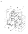
- a semiconductor manufacturing apparatus 10 as a substrate processing apparatus is a batch type vertical heat treatment apparatus and includes a housing 12 in which a main part is arranged.
- a hoop (hereinafter referred to as a pod) 16 is used as a wafer carrier as a substrate container for storing a wafer 14 (see FIG. 2) as a substrate made of, for example, SiC.
- a pod stage 18 is disposed on the front side of the housing 12, and the pod 16 is conveyed to the pod stage 18. For example, 25 wafers 14 are stored in the pod 16 and set on the pod stage 18 with the lid closed.
- a pod transfer device 20 is disposed at a position facing the pod stage 18 in front of the housing 12.
- a pod storage shelf 22, a pod opener 24, and a substrate number detector 26 are disposed in the vicinity of the pod transfer device 20.
- the pod storage shelf 22 is disposed above the pod opener 24 and is configured to hold a plurality of pods 16 mounted thereon.
- the substrate number detector 26 is disposed adjacent to the pod opener 24, and the pod transfer device 20 transfers the pod 16 among the pod stage 18, the pod storage shelf 22, and the pod opener 24.
- the pod opener 24 opens the lid of the pod 16, and the substrate number detector 26 detects the number of wafers 14 in the pod 16 with the lid opened.
- the substrate transfer machine 28 has an arm (tweezer) 32, and has a structure that can be moved up and down and rotated by a driving means (not shown).
- the arm 32 can take out, for example, five wafers 14. By moving the arm 32, the wafer 14 is transferred between the pod 16 and the boat 30 placed at the position of the pod opener 24.
- the boat 30 is made of a heat-resistant material such as carbon graphite or SiC, for example, and a plurality of wafers 14 are arranged in a horizontal posture and aligned with their centers aligned, and are stacked and held in the vertical direction. It is configured.
- a boat heat insulating portion 34 is disposed as a disk-shaped heat insulating member made of a heat resistant material such as quartz or SiC at the lower portion of the boat 30, and heat from the heated body 48 to be described later is processed. It is comprised so that it may become difficult to be transmitted to the downward side of the furnace 40 (refer FIG. 2).
- the processing furnace 40 is disposed in the upper part on the back side in the housing 12.
- the boat 30 loaded with a plurality of wafers 14 is loaded into the processing furnace 40 and subjected to heat treatment.
- the processing furnace 40 is provided with a first gas supply nozzle 60 having a first gas supply port 68, a second gas supply nozzle 70 having a second gas supply port 72, and a first gas exhaust port 90. It is done. In addition, a third gas supply port 360 and a second gas exhaust port 390 for supplying an inert gas are shown.
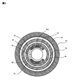
- the processing furnace 40 is made of a heat resistant material such as quartz or SiC, and includes a reaction tube 42 formed in a cylindrical shape with a closed upper end and an opened lower end. Below the reaction tube 42, a manifold 36 is disposed concentrically with the reaction tube 42.
- the manifold 36 is made of, for example, stainless steel and is formed in a cylindrical shape with an upper end and a lower end opened.
- the manifold 36 is provided to support the reaction tube 42.
- An O-ring (not shown) as a seal member is provided between the manifold 36 and the reaction tube 42. Since the manifold 36 is supported by a holding body (not shown), the reaction tube 42 is installed vertically.
- a reaction vessel is formed by the reaction tube 42 and the manifold 36.
- the processing furnace 40 includes a to-be-derivatized 48 as a body to be heated and a induction coil 50 as a magnetic field generator, which are formed in a cylindrical shape whose upper end is closed and whose lower end is open.
- a reaction chamber 44 is formed in a cylindrical hollow portion of the to-be-derivatized 48, and is configured to be able to store a boat 30 holding a wafer 14 as a substrate made of SiC or the like. Further, as shown in the lower frame of FIG. 2, the wafer 14 is held by the boat 30 in a state where the wafer 14 is held by the annular lower wafer holder 15b and the upper surface is covered by the disk-like upper wafer holder 15a. Good.
- the wafer 14 can be protected from particles falling from the upper part of the wafer, and film formation on the back surface side with respect to the film formation surface (lower surface of the wafer 14) can be suppressed. Further, the film forming surface can be separated from the boat column by the amount of the wafer holder 15, and the influence of the boat column can be reduced.
- the boat 30 is configured to hold the wafers 14 held by the wafer holder 15 so as to be aligned in the vertical direction in a horizontal posture and with the centers aligned.
- the derivative 48 is heated by a magnetic field generated by an induction coil 50 provided outside the reaction tube 42, and the reaction chamber 44 is heated when the derivative 48 generates heat. It is like.
- a temperature sensor (not shown) is provided as a temperature detector for detecting the temperature in the reaction chamber 44.
- the induction coil 50 and the temperature sensor are electrically connected to the temperature control unit 52, and the inside of the reaction chamber 44 is adjusted by adjusting the degree of energization to the induction coil 50 based on the temperature information detected by the temperature sensor.
- the temperature is controlled at a predetermined timing so as to obtain a desired temperature distribution (see FIG. 5).
- a structure 300 (see FIG. 3) extending in the vertical direction and having an arc-shaped cross section is preferably provided in the reaction chamber 44.
- the structure 300 is preferably made of a heat insulating material, carbon felt or the like, heat resistance and generation of particles can be suppressed.
- a heat insulating material 54 made of, for example, a carbon felt that is not easily dielectric is provided. By providing the heat insulating material 54, the heat of the to-be-derivatized 48 is changed to the reaction tube 42 or Can suppress the transmission to the outside of the reaction tube 42.
- an outer heat insulating wall 55 having, for example, a water cooling structure is provided outside the induction coil 50 so as to prevent heat in the reaction chamber 44 from being transmitted to the outside so as to surround the reaction chamber 44.
- a magnetic seal 58 for preventing the magnetic field generated by the induction coil 50 from leaking outside is provided outside the outer heat insulating wall 55.
- a first gas supply nozzle 60 provided with at least one first gas supply port 68 is installed between the derivative 48 and the wafer 14. Further, a second gas supply nozzle 70 provided with at least one second gas supply port 72 is provided at a location different from the first gas supply nozzle 60 between the derivative 48 and the wafer 14. .
- the first gas exhaust port 90 is also disposed between the derivative 48 and the wafer 14.
- a third gas supply port 360 and a second gas exhaust port 390 are disposed between the reaction tube 42 and the heat insulating material 54. The gas types supplied from the first gas supply nozzle 60 and the second gas supply nozzle 70 will be described later.
- the first gas supply port 68 and the first gas supply nozzle 60 are made of carbon graphite, for example, and are provided in the reaction chamber 44.
- the first gas supply nozzle 60 is attached to the manifold 36 so as to penetrate the manifold 36.
- the first gas supply nozzle 60 is connected to the gas supply unit 200 via the first gas line 222.
- the second gas supply port 72 is made of, for example, carbon graphite and is provided in the reaction chamber 44.
- the second gas supply nozzle 70 is attached to the manifold 36 so as to penetrate the manifold 36. Further, the second gas supply nozzle 70 is connected to the gas supply unit 200 via the second gas line 260.
- one first gas supply port 68 and one second gas supply port 72 may be provided in the arrangement region of the substrate. Alternatively, it may be provided for every predetermined number of wafers 14.
- a first gas exhaust port 90 is provided below the boat 30, and a gas exhaust pipe 230 connected to the first gas exhaust port 90 is provided in the manifold 36 so as to pass therethrough.
- a vacuum exhaust device 220 such as a vacuum pump is connected to the downstream side of the gas exhaust pipe 230 via a pressure sensor (not shown) as a pressure detector and an APC (Auto Pressure Controller) valve 214 as a pressure regulator.
- a pressure control unit 98 is electrically connected to the pressure sensor and the APC valve 214, and the pressure control unit 98 adjusts the opening degree of the APC valve 214 based on the pressure detected by the pressure sensor, thereby processing furnace. Control is performed at a predetermined timing so that the pressure in 40 becomes a predetermined pressure (see FIG. 5).
- the gas supplied from the first gas supply port 68 and the second gas supply port 72 flows in parallel to the wafer 14 made of Si or SiC, and is exhausted from the first gas exhaust port 90. Therefore, the entire wafer 14 is exposed to the gas efficiently and uniformly.
- a boat heat insulating part 34A is provided under the boat 30 so that the manifold 36 and the like are not heated by the radiant heat from the reaction chamber. Further, in the present embodiment, heat exchange is performed to reduce the temperature of the deposition gas by performing heat exchange with the deposition gas so that the deposition gas heated in the reaction chamber does not reach the manifold 36 or the like at a high temperature.
- the boat heat insulating portion 34A has a hollow cylindrical shape, and the film forming gas is exhausted along the side surface.
- the 2nd heat exchange part provided in the lower part of the 1st heat exchange part 34B and the gas supply nozzle 60 (70) is provided so that the said boat heat insulation part 34A may be enclosed.
- the first heat exchange part 34B and the second heat exchange part 34C are arranged so as to have a gap with the boat heat insulating part 34A, and the film formation gas in the reaction chamber 44 passes through the flow path of the film formation gas to be exhausted. It is narrower than the flow path. Thereby, since the film forming gas is exhausted through the narrow flow path, the efficiency of heat exchange is further improved.
- the third gas supply port 360 is disposed between the reaction tube 42 and the heat insulating material 54 and attached so as to penetrate the manifold 36.
- the second gas exhaust port 390 is disposed between the reaction tube 42 and the heat insulating material 54 so as to face the third gas supply port 360, and the second gas exhaust port 390 is a gas It is connected to the exhaust pipe 230.
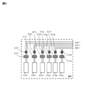
- the third gas supply port 360 is formed in a third gas line 240 that penetrates the manifold 36, and the third gas line 240 is connected to the gas supply unit 200. As shown in FIG. 4, the third gas line 240 is connected to a gas supply source 210f via a valve 212f and an MFC 211f.
- a rare gas Ar gas is supplied as an inert gas from the gas supply source 210f, and a gas contributing to the growth of the SiC epitaxial film is prevented from entering between the reaction tube 42 and the heat insulating material 54. It is possible to prevent unnecessary products from adhering to the inner wall of 42 or the outer wall of the heat insulating material 54.
- the inert gas supplied between the reaction tube 42 and the heat insulating material 54 is exhausted from the vacuum exhaust device 220 via the APC valve 214 on the downstream side of the gas exhaust tube 230 from the second gas exhaust port 390. Is done.
- the first gas line 222 includes mass flow controllers (hereinafter referred to as MFC) 211a and 211b as flow rate controllers (flow rate control means) for SiH 4 gas, HCl gas, and inert gas.
- MFC mass flow controllers
- 211c and valves 212a, 212b, 212c are connected to an SiH4 gas supply source 210a, an HCl gas supply source 210b, and an inert gas supply source 210c.
- the supply flow rate, concentration, partial pressure, and supply timing of SiH 4 gas, HCl gas, and inert gas can be controlled in the reaction chamber 44.
- the valves 212a, 212b, and 212c and the MFCs 211a, 211b, and 211c are electrically connected to the gas flow rate control unit 78, and are controlled at a predetermined timing so that the flow rate of the supplied gas becomes a predetermined flow rate. (See FIG. 5).
- a first gas supply system is configured as a gas supply system by at least one first gas supply port 68 provided in the first gas supply nozzle 60.
- the second gas line 260 is connected to the C3H8 gas supply source 210d through the MFC 211d and the valve 212d as a flow rate control unit for C3H8 gas, for example, as C (carbon) atom-containing gas, and as the reducing gas,
- the H2 gas is connected to the H2 gas supply source 210e via the MFC 211e as a flow rate control means and a valve 212e.
- the supply flow rate, concentration, and partial pressure of C3H8 gas and H2 gas can be controlled in the reaction chamber 44.
- the valves 212d and 212e and the MFCs 211d and 211e are electrically connected to the gas flow rate control unit 78, and are controlled at a predetermined timing so that the supplied gas flow rate becomes a predetermined flow rate ( (See FIG. 5).
- Gas supply is provided by gas supply sources 210d and 210e of C3H8 gas and H2 gas, valves 212d and 212e, MFCs 211d and 211e, a second gas line 260, a second gas supply nozzle 70, and a second gas supply port 72.
- a second gas supply system is configured as the system.
- a reducing gas such as hydrogen gas may be used in order to use the Si atom-containing gas more efficiently.
- the reducing gas is supplied together with the C atom-containing gas and mixed with the Si atom-containing gas in the reaction chamber 44, so that the reducing gas is reduced. Therefore, the decomposition of the Si atom-containing gas is compared with that during film formation. Therefore, the deposition of the Si film in the first gas supply nozzle can be suppressed.
- the reducing gas can be used as a carrier gas for the C atom-containing gas. Note that the use of an inert gas (particularly a rare gas) such as argon (Ar) as the carrier of the Si atom-containing gas can suppress the deposition of the Si film.
- a chlorine atom-containing gas such as HCl
- the Si atom-containing gas is decomposed by heat and can be deposited in the first gas supply nozzle 60, it becomes possible to enter the etching mode with chlorine, and the first gas supply It becomes possible to further suppress the deposition of the Si film in the nozzle 60.
- the chlorine atom-containing gas also has an effect of etching the deposited film, and the first gas supply port 68 can be prevented from being blocked.
- HCl gas was illustrated as Cl (chlorine) atom containing gas sent when forming a SiC epitaxial film
- chlorine gas may be used.
- SiCl4 and Gas tetrachlorosilane
- SiHCl3 trichlorosilane
- SiH2Cl2 dichlorosilane
- the gas containing Si atoms and Cl atoms is also a Si atom-containing gas or a mixed gas of Si atom-containing gas and Cl atom-containing gas.
- SiCl4 is desirable from the viewpoint of suppressing the consumption of Si in the nozzle because the temperature at which it is thermally decomposed is relatively high.
- C3H8 gas was illustrated as a C (carbon) atom containing gas in the above-mentioned, you may use ethylene (henceforth C2H4) gas and acetylene (henceforth C2H2) gas.
- H2 gas is exemplified as the reducing gas
- the present invention is not limited to this, and other H (hydrogen) atom-containing gas may be used.
- the carrier gas at least one of rare gases such as Ar (argon) gas, He (helium) gas, Ne (neon) gas, Kr (krypton) gas, and Xe (xenon) gas may be used.
- rare gases such as Ar (argon) gas, He (helium) gas, Ne (neon) gas, Kr (krypton) gas, and Xe (xenon) gas may be used.
- a mixed gas in which the above gases are combined may be used.
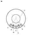
- FIG. 6 is a schematic diagram showing only necessary members for easy understanding.
- the distribution of the mixing degree of the two gases in the wafer surface in the case of SiC epitaxial growth (C / Si ratio distribution in the wafer surface) is important.
- three second gas supply nozzles 70 are provided, and the first gas supply nozzle 60 is provided so as to be sandwiched between the second gas supply nozzles 70. It is configured.
- the first gas supply nozzle 60 is provided so as to be sandwiched between the second gas supply nozzles 70. It is configured.
- the flow rate of the gas that becomes the main flow of the field By adjusting the ratio (center / both ends), the gas flow on the wafer can be controlled, and the in-plane film thickness can be easily controlled.
- a gas in this embodiment, H2 gas
- the first gas supply port 68 is arranged so that the direction of the first gas supply port 68 faces outward with respect to the direction of the second gas supply port 72. That is, as shown in FIG. 6, the intersection (B) in the direction in which the first gas supply port 68 is directed from the intersection (A) in the direction in which the second gas supply ports 72 at both ends are directed is the gas. It arrange
- the film forming gas (carbon atom-containing gas and hydrogen gas) supplied from the second gas supply port 72 arranged in the center is supplied from the first gas supply ports 68 arranged on the left and right.
- the silicon atom-containing gas supplied from the adjacent first gas supply ports 68 diffuses into the film forming gas supplied from the second gas supply ports 72 arranged at both ends. Accordingly, the amount of the silicon atom-containing gas that diffuses toward the second gas supply port 72 disposed in the center is larger than the amount of the silicon atom-containing gas that diffuses toward both ends.
- the silicon gas supplied from the first gas supply port 68 for each film forming gas supplied from the second gas supply port 72 can be adjusted, and a uniform C / Si ratio can be realized in the wafer plane.
- each of the first gas supply ports 68 be directed at least in a crossing direction.
- the flow rate of the film forming gas (silicon atom-containing gas or the like) supplied from the first gas supply port 68 is the same as that of the film forming gas (carbon atom containing gas) supplied from the second gas supply port 72 which is the mainstream of the field. It should be slower than the flow rate of gas or hydrogen gas. The slower the flow rate, the greater the diffusion of the silicon atom-containing gas, so the degree of mixing of the two types of gas is improved.
- a seal cap 102 is provided as a furnace port lid for hermetically closing the lower end opening of the processing furnace 40.
- the seal cap 102 is made of a metal such as stainless steel and is formed in a disk shape.
- An O-ring (not shown) is provided on the upper surface of the seal cap 102 as a sealing material that comes into contact with the lower end of the processing furnace 40.
- the seal cap 102 is provided with a rotation mechanism 104, and the rotation shaft 106 of the rotation mechanism 104 is connected to the boat 30 through the seal cap 102, and the wafer 14 is rotated by rotating the boat 30. It is configured.
- seal cap 102 is configured as a lifting mechanism provided outside the processing furnace 40 so as to be vertically lifted by a lifting motor 122 which will be described later. It is possible to carry in and out.
- a drive control unit 108 is electrically connected to the rotation mechanism 104 and the lifting motor 122, and is configured to control at a predetermined timing so as to perform a predetermined operation (see FIG. 5).
- a lower substrate 112 is provided on the outer surface of the load lock chamber 110 as a spare chamber.
- the lower substrate 112 is provided with a guide shaft 116 that is slidably fitted to the lifting platform 114 and a ball screw 118 that is screwed to the lifting platform 114.
- an upper substrate 120 is provided at the upper ends of the guide shaft 116 and the ball screw 118 erected on the lower substrate 112.
- the ball screw 118 is rotated by an elevating motor 122 provided on the upper substrate 120, and the elevating platform 114 is moved up and down by rotating the ball screw 118.
- a hollow elevating shaft 124 is vertically suspended from the elevating platform 114, and the connecting portion between the elevating platform 114 and the elevating shaft 124 is airtight, and the elevating shaft 124 moves up and down together with the elevating platform 114.
- the elevating shaft 124 passes through the top plate 126 of the load lock chamber 110, and a sufficient clearance is formed in the through hole of the top plate 126 through which the elevating shaft 124 passes so that the elevating shaft 124 does not contact the top plate 126. Has been.
- a bellows 128 is provided as a hollow elastic body having elasticity so as to cover the periphery of the lifting shaft 124 between the load lock chamber 110 and the lifting platform 114, and the load lock chamber 110 is hermetically sealed by the bellows 128. It is supposed to be kept.
- the bellows 128 has a sufficient amount of expansion and contraction that can accommodate the amount of elevation of the lifting platform 114, and the inner diameter of the bellows 128 is sufficiently larger than the outer diameter of the lifting shaft 124. It is comprised so that 124 may not contact.
- the elevating board 130 is horizontally fixed to the lower end of the elevating shaft 124, and the drive unit cover 132 is airtightly attached to the lower surface of the elevating board 130 via a seal member such as an O-ring.
- the elevating board 130 and the drive unit cover 132 constitute a drive unit storage case 134, and this configuration isolates the inside of the drive unit storage case 134 from the atmosphere in the load lock chamber 110.
- the rotation mechanism 104 of the boat 30 is provided inside the drive unit storage case 134, and the periphery of the rotation mechanism 104 is cooled by a cooling mechanism 135.
- the power cable 138 passes through the hollow portion from the upper end of the elevating shaft 124 and is guided to the rotation mechanism 104 and connected thereto.
- a cooling water flow path 140 is formed in the cooling mechanism 135 and the seal cap 102. Further, a cooling water pipe 142 is led from the upper end of the elevating shaft 124 through the hollow portion to the cooling water flow path 140 and connected thereto.
- the drive unit storage case 134 is raised and lowered via the elevating table 114 and the elevating shaft 124.
- the seal cap 102 provided in an airtight manner on the elevating substrate 130 closes the furnace port 144, which is an opening of the processing furnace 40, so that wafer processing is possible. Further, when the drive unit storage case 134 is lowered, the boat 30 is lowered together with the seal cap 102, and the wafer 14 can be carried out to the outside.
- the temperature control unit 52, the gas flow rate control unit 78, the pressure control unit 98, and the drive control unit 108 constitute an operation unit and an input / output unit, and are electrically connected to a main control unit 150 that controls the entire semiconductor manufacturing apparatus 10. ing.
- the temperature control unit 52, the gas flow rate control unit 78, the pressure control unit 98, and the drive control unit 108 are configured as a controller 152.
- the pod 16 storing a plurality of wafers 14 is set on the pod stage 18 shown in FIG. 1, the pod 16 is transferred from the pod stage 18 to the pod storage shelf 22 by the pod transfer device 20 and stocked.
- the pod 16 stocked on the pod storage shelf 22 is transported and set to the pod opener 24 by the pod transport device 20, the lid of the pod 16 is opened by the pod opener 24, and the pod 16 is detected by the substrate number detector 26. The number of wafers 14 housed in is detected.
- the wafer 14 is taken out from the pod 16 at the position of the pod opener 24 by the substrate transfer machine 28 and transferred to the boat 30.
- the boat 30 holding the wafers 14 includes a lifting platform 114 (see FIG. 7) and a lifting shaft 124 by a lifting motor 122 (see FIG. 7). Is carried into the reaction chamber 44 (boat loading). In this state, the seal cap 102 is in a state of sealing the lower end of the manifold 36 via an O-ring (not shown).
- the reaction chamber 44 is evacuated by the evacuation device 220 so that the inside of the reaction chamber 44 becomes a predetermined pressure (degree of vacuum).
- the pressure in the reaction chamber 44 is measured by a pressure sensor (not shown), and the APC valve 214 communicating with the first gas exhaust port 90 and the second gas exhaust port 390 based on the measured pressure is used. Feedback controlled.
- the derivative 48 is heated so that the inside of the wafer 14 and the reaction chamber 44 has a predetermined temperature.
- the current supply to the induction coil 50 is feedback controlled based on temperature information detected by a temperature sensor (not shown) so that the reaction chamber 44 has a predetermined temperature distribution.
- the boat 30 is rotated by the rotation mechanism 104, the wafer 14 is rotated in the circumferential direction.
- Si (silicon) atom-containing gas and Cl (chlorine) atom-containing gas contributing to the SiC epitaxial growth reaction are supplied from gas supply sources 210a and 210b, respectively, and the reaction chamber 44 is supplied from the first gas supply port 68. Erupted inside. Further, after the opening degrees of the corresponding MFCs 211d and 211e are adjusted so that the C (carbon) atom-containing gas and the reducing gas H2 gas have a predetermined flow rate, the valves 212d and 212e are opened, The gas flows through the second gas line 260, flows through the second gas supply nozzle 70, and is introduced into the reaction chamber 44 through the second gas supply port 72.
- the gas supplied from the first gas supply port 68 and the second gas supply port 72 passes through the inside of the derivative 48 in the reaction chamber 44 and passes through the gas exhaust pipe 230 from the first gas exhaust port 90. Exhausted.
- the gas supplied from the first gas supply port 68 and the second gas supply port 72 passes through the reaction chamber 44, the gas contacts the wafer 14 made of SiC or the like, and the SiC is formed on the surface of the wafer 14. Epitaxial film growth is performed.
- the film-forming gas supplied from the two first gas supply nozzles 60 is ejected in a direction in which the ejection directions intersect.
- the film forming gas supplied from the three second gas supply nozzles 70 is ejected in a direction in which the ejection directions intersect. Furthermore, the point where the film forming gas supplied from the first gas supply nozzle 60 intersects is supplied so as to be farther from the point where the film forming gas supplied from the second gas supply nozzle 70 intersects. This makes it possible to make the concentration distribution in the wafer 14 surface uniform.
- the valve 212f is opened and the third gas line is opened.
- 240 is supplied to the reaction chamber 44 from the third gas supply port 360.
- Ar gas which is a rare gas as an inert gas supplied from the third gas supply port 360 passes between the heat insulating material 54 in the reaction chamber 44 and the reaction tube 42, and the second gas exhaust port 390. Exhausted from.
- the seal cap 102 is lowered by the elevating motor 122 (see FIG. 7), the lower end of the manifold 36 is opened, and the reaction tube 42 is opened from the lower end of the manifold 36 while the processed wafer 14 is held by the boat 30.
- the boat 30 is made to stand by at a predetermined position until the wafer 14 which has been unloaded (boat unloading) and held on the boat 30 is cooled.
- the wafer 14 (see FIG. 2) is taken out from the boat 30 by the substrate transfer device 28 shown in FIG. 1 and set in the pod opener 24. It is transported and stored in an empty pod 16. Thereafter, the pod 16 in which the wafers 14 are stored is transferred to the pod storage shelf 22 or the pod stage 18 by the pod transfer device 20. In this way, a series of operations of the semiconductor manufacturing apparatus 10 is completed.
- FIGS. 8 and 9 differ from the above-described embodiment in the configuration of the gas supply nozzle.
- two kinds of film forming gases are separately supplied so that deposits such as SiC films do not adhere in the gas supply nozzle as in the present embodiment, two kinds of film forming gases are provided in the vicinity of the gas supply port.
- the SiC film is deposited near the gas supply port.
- the gas supply port is clogged and the like, particles are generated, the flow rate is changed, etc., and there is a possibility that a homogeneous film cannot be formed.
- the first gas supply port 68 and the second gas supply port as shown in FIG. the portion where the film forming gas is ejected is a curved surface. Thereby, the location where a deposit adheres becomes wide with respect to a gas supply port, and can block
- the first gas supply nozzle 60 has a wall extending from the first gas supply port 68 in the direction in which the film forming gas is ejected.
- the film forming gas ejected from the first gas supply port 68 comes into contact with the wall, and the speed thereof is reduced. Therefore, the film forming gas ejected from the first gas supply port 68 is in a state of being easily diffused after being supplied into the reaction chamber, and the film forming gas supplied from the second gas supply port 72 Mixing can be facilitated.
- the width of the wall in the direction parallel to the wafer surface is larger than the width of the first gas supply port 68 in the direction parallel to the wafer surface. As a result, the flow of the gas ejected from the first gas supply port 68 spreads a little in the region where the wall is installed, and the speed further decreases.
- the second gas supply nozzle 70 does not have a wall extending in the direction in which the film formation gas is ejected. It has a configuration in which the vicinity of jetting is a curved surface.
- the second gas supply port 72 can supply the reducing gas (hydrogen gas), which is the mainstream of the field, into the reaction chamber without a decrease in speed. Accordingly, the distance from the second gas supply port 72 to the tip of the second gas supply nozzle 70 in the ejection direction of the film formation gas is the film formation gas of the first gas supply nozzle 60 from the first gas supply port 68. It is shorter than the distance to the tip in the ejection direction.
- the curved surface provided in the second gas supply nozzle is not provided by cutting the gas supply port 72, but the gas supply port side of the cylindrical gas supply nozzle is thickened and the thickened portion is cut. It is formed by. Therefore, as shown in FIG. 9B, the second gas supply nozzle 70 has a linear second gas supply port 72 formed, and a gas ejection direction from the end of the second gas supply port 72. It has the structure which has the chamfering part which spreads gradually toward. In this way, by forming the chamfered portion thickly, the plurality of gas supply ports 72 provided in one gas supply nozzle 70 can be made substantially the same regardless of the chamfering processing accuracy.
- both the first gas supply nozzle 60 and the second gas supply nozzle 70 have a curved portion of the film formation gas ejection portion, so that the gas supply port 68 (72) is supplied with gas.
- the ejection portion can be widened, and the clogging of the nozzle due to the deposit can be suppressed.
- the first gas supply nozzle 60 is provided with a wall extending from the first gas supply port 68 in the direction in which the film forming gas is ejected, thereby reducing the speed of the film forming gas and diffusing in the reaction chamber. Can be promoted.
- the second gas supply port 72 can maintain the flow velocity by not providing a wall.
- the wall extending from the first gas supply port 68 in the direction in which the film forming gas is ejected is configured to surround the first gas supply port 68, but the plurality of first gas supply ports May be inserted.
- the modification shown in FIG. 10 differs from the embodiment shown in FIG. 9, for example, in the arrangement of the gas supply ports of the gas supply nozzle.
- one gas supply port of the gas supply nozzle is provided at the same height.
- the plurality of first gas supply ports 68 of the first gas supply nozzle 60 are arranged in a line along the height direction in which the gas supply nozzle 60 extends.
- the plurality of second gas supply ports 72 of the second gas supply nozzle 70 are arranged in a line along the height direction in which the gas supply nozzle 70 extends.
- two (a plurality of) gas supply ports are provided at the same height of the gas supply nozzle.
- the plurality of first gas supply ports 68 of the first gas supply nozzle 60 are arranged in two rows (a plurality of rows) along the height direction in which the gas supply nozzle 60 extends.
- the plurality of second gas supply ports 72 of the second gas supply nozzle 70 are arranged in two rows (a plurality of rows) along the height direction in which the gas supply nozzle 70 extends. Yes.
- the two gas supply ports arranged at each height are provided so as to form a constant central angle.
- the arrangement of the first row and the arrangement of the second row of the first gas supply ports 62 arranged in the gas supply nozzle 60 are arranged so as to form a constant center angle.
- the gas supply port (the first gas supply port 68 or the first gas supply nozzle 68) is arranged so that the gas direction supplied by one gas supply nozzle (the first gas supply nozzle 60 or the second gas supply nozzle 70) becomes two directions.
- Two gas supply ports 72) are provided. Thereby, the mixing degree of two types of gas in the wafer surface can be made uniform.
- the gas supply port arrangement method as shown in FIG. 10 may be provided in both the silicon atom-containing gas supply nozzle and the carbon atom-containing gas supply nozzle, or may be provided in only one of the nozzles. .
- the arrangement method of the gas supply ports can be selected according to the position of the gas supply nozzle with respect to the wafer, instead of selecting the arrangement method shown in FIG. For example, when a plurality of gas supply nozzles are installed along the circumference of the wafer (see, for example, FIG. 6 and FIG. 8), only the gas supply nozzles at both ends of the plurality of gas supply nozzles are provided. Etc., and can be installed with appropriate changes according to the necessary conditions.
- the following modifications can be applied as further modifications of the gas supply nozzle shown in FIG. That is, of the two (a plurality of) gas supply ports arranged at the same height, the opening diameter of one gas supply port is formed to be smaller than the opening diameter of the other gas supply port. And when multiple gas supply nozzles are installed along the circumference of the wafer, the opening diameter of the gas supply port facing the center of the wafer is larger than the opening diameter of the gas supply port facing the peripheral edge of the wafer. Is also arranged to be relatively small. Thereby, the gas mixing degree can be further improved.
- the opening diameters can be made different depending on the height at which the gas supply ports are arranged.
- the opening diameter of the gas supply port arranged at the first height is made larger than the opening diameter of the gas supply port arranged at the second height lower than the first height.
- the opening diameter of the gas supply port arranged at the first height is made smaller than the opening diameter of the gas supply port arranged at the second height lower than the first height.
- the second gas supply port 72 is described so that the direction of the second gas supply port 72 intersects at the center of the wafer 14, but this is not restrictive.
- the direction of the first gas supply port 68 intersects with the center of the wafer 14, and the direction of the second gas supply port 72 intersects with the front of the wafer 14 (on the first gas supply port 68 side).
- the direction of the second gas supply port 72 may intersect with the distance from the center of the wafer 14.
- the direction of the first gas supply port 68 is configured to intersect at a distance from the point where the direction of the second gas supply port 72 intersects.
- the second gas supply port 72 is preferably configured to intersect at the center of the wafer 14 as described in FIG. The reason for this is that if the crossing is made far from the center of the wafer 14, the gas supplied from the second gas supply port 72 arranged on the outer side is directed toward the wafer holder 15 a, and the wafer 14 This is because the gas flow on the center line of the wafer 14 (the direction in which the second gas supply port in the middle is facing) may become too strong if it is configured to intersect near the center.
- a reaction chamber for processing a plurality of substrates A heating unit provided to surround the reaction chamber; A boat placed in the reaction chamber in a state of holding the plurality of substrates; A first gas supply nozzle installed in the reaction chamber; Second and third gas supply nozzles installed so as to sandwich the first gas supply nozzle in the reaction chamber; A fourth gas supply nozzle installed so as to sandwich the first gas supply nozzle and the second gas supply nozzle in the reaction chamber; A fifth gas supply nozzle installed so as to sandwich the first gas supply nozzle and the third gas supply nozzle in the reaction chamber; A plurality of first gas supply ports that are provided in the first gas supply nozzle and supply a first gas containing a first film-forming gas toward the plurality of substrates; A plurality of second gas supply ports that are provided in the second gas supply nozzle and supply a second gas containing a second film formation gas different from the first film formation gas toward the plurality of substrates; A plurality of first gas supply ports that are provided in the first gas supply nozzle and supply a first gas containing a second film
- the substrate processing apparatus which is farther from the first gas supply nozzle than the point where the direction in which the fifth gas supply port faces intersects.
- Appendix 2 In Appendix 1, The substrate processing apparatus configured such that flow rates of the first gas, the fourth gas, and the fifth gas are faster than flow rates of the second gas and the third gas.
- Appendix 3 In Appendix 1 or Appendix 2, The first film-forming gas is a carbon atom-containing gas, The second film-forming gas is a silicon atom-containing gas, The substrate processing apparatus, wherein the first gas, the fourth gas, and the fifth gas include a reducing gas.
- Each of the first to fifth gas supply nozzles is a substrate processing apparatus in which a portion from which a corresponding gas is ejected is curved.
- the second gas supply nozzle has a wall extending in the ejection direction of the second gas from the plurality of second gas supply ports, The substrate processing apparatus, wherein the third gas supply nozzle has a wall extending from the plurality of third gas supply ports in the ejection direction of the third gas.
- the curved surface of the jetting portion of the first gas supply nozzle is provided so as to gradually spread from the ends of the plurality of first gas supply ports provided linearly in the jet direction of the first gas
- the curved surface of the portion to be ejected of the fourth gas supply nozzle is provided so as to gradually spread from the ends of the plurality of fourth gas supply ports provided linearly in the ejection direction of the fourth gas
- the curved surface of the jetting portion of the fifth gas supply nozzle is provided so as to gradually spread from the ends of the plurality of fifth gas supply ports provided linearly in the jet direction of the fifth gas. Processing equipment.
- the second gas supply nozzle has a wall extending in the ejection direction of the second gas from the plurality of second gas supply ports
- the third gas supply nozzle has a wall extending in the ejection direction of the third gas from the plurality of third gas supply ports
- the curved surface of the jetting portion of the first gas supply nozzle is provided so as to gradually spread from the ends of the plurality of first gas supply ports provided linearly in the jet direction of the first gas
- the curved surface of the portion to be ejected of the fourth gas supply nozzle is provided so as to gradually spread from the ends of the plurality of fourth gas supply ports provided linearly in the ejection direction of the fourth gas
- the curved surface of the jetting part of the fifth gas supply nozzle is provided so as to gradually spread from the ends of the plurality of fifth gas supply ports provided linearly in the jetting direction of the fifth gas, The distance from the end of the corresponding gas supply port of the first, fourth, and fifth gas supply nozzles to the end of the corresponding
- the substrate processing apparatus is shorter than the distance from the end of the wall to the corresponding wall end.
- Appendix 8 A boat loading process for carrying a plurality of substrates into the reaction chamber while being held in the boat;
- the first film forming gas is supplied to the plurality of substrates in a direction intersecting with each other from at least two first gas supply nozzles, and in a direction intersecting with each other from at least two second gas supply nozzles.
- the first film-forming gas is supplied in such a direction that a point where the directions in which the first film-forming gas is supplied intersects with each other is farther from a point where the direction in which the second film-forming gas is supplied intersects with each other.
- SYMBOLS 10 Semiconductor manufacturing apparatus, 12: Housing
Abstract
シリコン含有ガスと炭素原子含有ガスとを夫々独立したガス供給ノズルにより供給する場合の夫々のガスの混合度の面内分布を均一化させる。シリコン原子含有ガスを供給する第1ガス供給ノズル(60)と炭素原子含有ガス及び還元ガスを供給する第2ガス供給ノズル70とを交互になるように奇数本配置する。また、第1ガス供給口(68)は、そのガス噴出方向の交点(B)が第2ガス供給口72のガス噴出方向の交点(A)より遠くなるようにその向きが決められる。
Description
本発明は、基板を処理する基板処理装置、半導体デバイスの製造方法及び基板の製造方法、特に炭化ケイ素(以下、SiCとする)エピタキシャル膜を基板上に成膜する工程を有する基板処理装置、半導体デバイスの製造方法及び基板製造方法に関するものである。
SiCは、特にパワーデバイス用素子材料として注目されている。一方で、SiCはシリコン(以下Siとする)に比べて結晶基板やデバイスの作製が難しいことが知られている。
一方で、SiCを用いてデバイスを作製する場合は、SiC基板の上にSiCエピタキシャル膜を形成したウェーハを用いる。このSiC基板上にSiCエピタキシャル膜を形成するSiCエピタキシャル成長装置の一例として特許文献1がある。
特許文献1は、所謂縦型バッチ式熱処理装置により多数枚の基板に対して一度にSiCエピタキシャル成長膜を形成することが記載される。
また、特許文献1には、シリコン原子含有ガスと、炭素原子含有ガスとを分離して供給し、ノズル内の閉塞を抑制することが記載されている。
特許文献1に記載されるように、シリコン原子含有ガスを供給するガス供給ノズルと、炭素原子含有ガスを供給するガス供給ノズルとを夫々独立に反応室内に設けた場合、ガス供給口から噴出した夫々のガスをウェーハに到達するまでに十分混合する必要がある。特に、ウェーハ面内で2種類のガスの混合度が異なってしまうと、ウェーハ面内での膜質が悪くなってしまう。
そこで、本発明は、2種類のガスを夫々独立したガス供給ノズルで反応室に供給する際に、ウェーハ面内の当該2種類のガスの混合度を均一化することを目的とする。
本発明の一態様によれば、複数の基板を処理する反応室と、前記反応室を囲むように設けられる加熱部と、前記複数の基板を保持した状態で前記反応室内に載置されるボートと、前記反応室内に設置される第1ガス供給ノズルと、前記反応室内に前記第1ガス供給ノズルを挟むように設置される第2及び第3ガス供給ノズルと、前記反応室内に前記第1ガス供給ノズルと前記第2ガス供給ノズルを挟むように設置される第4ガス供給ノズルと、前記反応室内に前記第1ガス供給ノズルと前記第3ガス供給ノズルを挟むように設置される第5ガス供給ノズルと、前記第1ガス供給ノズルに設けられ、前記複数の基板に向けて第1成膜ガスを含む第1ガスを供給する複数の第1ガス供給口と、前記第2ガス供給ノズルに設けれ、前記複数の基板に向けて前記第1成膜ガスとは異なる第2成膜ガスを含む第2ガスを供給する複数の第2ガス供給口と、前記第3ガス供給ノズルに設けれ、前記複数の基板に向けて前記第2成膜ガスを含む第3ガスを供給する複数の第3ガス供給口と、前記第4ガス供給ノズルに設けられ、前記複数の基板に向けて前記第1成膜ガスを含む第4ガスを供給する複数の第4ガス供給口と、前記第5ガス供給ノズルに設けられ、前記複数の基板に向けて前記第1成膜ガスを含む第5ガスを供給する複数の第5ガス供給口と、を具備し、前記複数の第2ガス供給口の向いている方向と前記複数の第3ガス供給口の向いている方向とが交差する点は、前記複数の第4ガス供給口の向いている方向と前記複数の第5ガス供給口の向いている方向とが交差する点より、前記第1ガス供給ノズルに対し遠くなる基板処理装置が提供される。
また、本発明の他の一態様によれば、複数の基板をボートに保持した状態で反応室内に搬入するボートローディング工程と、前記複数の基板に対し、少なくとも2本の第1ガス供給ノズルから互いに交差するような方向に第1成膜ガスが供給され、少なくとも2本の第2ガス供給ノズルから互いに交差するような方向に第2成膜ガスが供給され、前記第1成膜ガスと前記第2成膜ガスとが混合することによりに前記複数の基板に所定の膜を形成する成膜工程と、前記成膜工程において成膜された前記複数の基板を前記反応室から搬出するボートアンローディング工程と、を有し、前記第1成膜ガスは、前記第1成膜ガスが供給される方向が互いに交差する点が前記第2成膜ガスが供給される方向が互いに交差する点より遠くなるような方向に供給される基板の製造方法又は半導体デバイスの製造方法が提供される。
ウェーハの膜質が向上する。
以下、図面を参照しつつ本発明の実施形態を説明する。以下の実施形態では、基板処理装置の一例であるSiCエピタキシャル成長装置における、高さ方向にSiCウェーハを並べる、所謂バッチ式縦型SiCエピタキシャル成長装置で説明する。なお、バッチ式縦型SiCエピタキシャル成長装置とすることで、一度に処理できるSiCウェーハの数が多くなりスループットが向上する。
<全体構成>
先ず、図1に於いて、本発明の第1の実施形態に於けるSiCエピタキシャル膜を成膜する基板処理装置、および、半導体デバイスの製造工程の一つであるSiCエピタキシャル膜を成膜する基板の製造方法について説明する。
先ず、図1に於いて、本発明の第1の実施形態に於けるSiCエピタキシャル膜を成膜する基板処理装置、および、半導体デバイスの製造工程の一つであるSiCエピタキシャル膜を成膜する基板の製造方法について説明する。
基板処理装置(成膜装置)としての半導体製造装置10は、バッチ式縦型熱処理装置であり、主要部が配置される筐体12を有する。前記半導体製造装置10には、例えばSiC等で構成された基板としてのウェーハ14(図2参照)を収納する基板収容器として、フープ(以下、ポッドと称す)16がウェーハキャリアとして使用される。前記筐体12の正面側には、ポッドステージ18が配置されており、該ポッドステージ18にポッド16が搬送される。ポッド16には、例えば25枚のウェーハ14が収納され、蓋が閉じられた状態で前記ポッドステージ18にセットされる。
前記筐体12内の正面であって、前記ポッドステージ18に対向する位置には、ポッド搬送装置20が配置されている。又、該ポッド搬送装置20の近傍にはポッド収納棚22、ポッドオープナ24及び基板枚数検知器26が配置されている。前記ポッド収納棚22は前記ポッドオープナ24の上方に配置され、ポッド16を複数個載置した状態で保持する様に構成されている。前記基板枚数検知器26は、前記ポッドオープナ24に隣接して配置され、前記ポッド搬送装置20は前記ポッドステージ18と前記ポッド収納棚22と前記ポッドオープナ24との間でポッド16を搬送する。前記ポッドオープナ24はポッド16の蓋を開けるものであり、前記基板枚数検知器26は蓋を開けられたポッド16内のウェーハ14の枚数を検知する様になっている。
前記筐体12内には、基板移載機28、基板保持具としてのボート30が配置されている。前記基板移載機28は、アーム(ツイーザ)32を有し、図示しない駆動手段により昇降可能且つ回転可能な構造となっている。前記アーム32は、例えば5枚のウェーハ14を取出すことができ、前記アーム32を動かすことにより、前記ポッドオープナ24の位置に置かれたポッド16及びボート30間にてウェーハ14を搬送する。
前記ボート30は、例えばカーボングラファイトやSiC等の耐熱性材料で構成されており、複数枚のウェーハ14を水平姿勢で、且つ互いに中心を揃えた状態で整列させて縦方向に積上げ、保持する様に構成されている。尚、前記ボート30の下部には、例えば石英やSiC等の耐熱性材料で構成された円盤形状の断熱部材としてボート断熱部34が配置されており、後述する被加熱体48からの熱が処理炉40の下方側に伝わりにくくなる様に構成されている(図2参照)。
前記筐体12内の背面側上部には前記処理炉40が配置されている。該処理炉40内に複数枚のウェーハ14を装填した前記ボート30が搬入され、熱処理が行われる。
<処理炉構成>
次に、図2、図3、図4に於いて、SiCエピタキシャル膜を成膜する前記半導体製造装置10の前記処理炉40について説明する。処理炉40には、第1のガス供給口68を有する第1のガス供給ノズル60、第2のガス供給口72を有する第2のガス供給ノズル70、及び第1のガス排気口90が設けられる。又、不活性ガスを供給する第3のガス供給口360、第2のガス排気口390が図示されている。
次に、図2、図3、図4に於いて、SiCエピタキシャル膜を成膜する前記半導体製造装置10の前記処理炉40について説明する。処理炉40には、第1のガス供給口68を有する第1のガス供給ノズル60、第2のガス供給口72を有する第2のガス供給ノズル70、及び第1のガス排気口90が設けられる。又、不活性ガスを供給する第3のガス供給口360、第2のガス排気口390が図示されている。
処理炉40は、石英又はSiC等の耐熱性材料からなり、上端が閉塞し下端が開口した円筒形状に形成された反応管42を備えている。反応管42の下方には、反応管42と同心円状にマニホールド36が配設されている。該マニホールド36は、例えばステンレス等からなり、上端及び下端が開口した円筒形状に形成されている。該マニホールド36は、反応管42を支持する様に設けられている。尚、マニホールド36と反応管42との間には、シール部材としてのOリング(図示せず)が設けられている。マニホールド36が図示しない保持体に支持されることにより、反応管42は垂直に据付けられた状態になっている。該反応管42とマニホールド36により、反応容器が形成されている。
処理炉40は、上端が閉塞し下端が開口した円筒形状に形成された被加熱体としての被誘導体48及び磁場発生部としての誘導コイル50を具備している。被誘導体48の筒中空部には、反応室44が形成されており、SiC等で構成された基板としてのウェーハ14を保持したボート30を収納可能に構成されている。また、図2の下枠内に示されるように、ウェーハ14は、円環状の下部ウェーハホルダ15bに保持され、上面を円板状の上部ウェーハホルダ15aで覆われた状態でボート30に保持されるとよい。これにより、ウェーハ上部から落下しているパーティクルからウェーハ14を守ることができると共に、成膜面(ウェーハ14の下面)に対して裏面側の成膜を抑制することができる。また、ウェーハホルダ15の分、ボート柱から成膜面を離すことができ、ボート柱の影響を小さくすることができる。ボート30は、水平姿勢で、且つ、互いに中心を揃えた状態で縦方向に整列するようにウェーハホルダ15に保持されたウェーハ14を保持するよう構成されている。被誘導体48は、該反応管42の外側に設けられた誘導コイル50により発生される磁場によって加熱される様になっており、被誘導体48が発熱することにより、反応室44内が加熱される様になっている。
被誘導体48の近傍には、反応室44内の温度を検出する温度検出体として図示しない温度センサが設けられている。誘導コイル50及び温度センサは、温度制御部52と電気的に接続されており、温度センサにより検出された温度情報に基づき、誘導コイル50への通電具合が調節されることで、反応室44内の温度が所望の温度分布となる様所定のタイミングにて制御される様構成されている(図5参照)。
尚、好ましくは、反応室44内に於いて前記第1及び第2のガス供給ノズル60,70と第1のガス排気口90との間であって、前記被誘導体48とウェーハ14との間には、被誘導体48とウェーハ14との間の空間を埋める様、鉛直方向に延在し断面が円弧状の構造物300(図3参照)を反応室44内に設けるのがよい。例えば、図3に示す様に、対向する位置にそれぞれ構造物300を設けることで、第1及び第2のガス供給ノズル60,70から供給されるガスが、被誘導体48の内壁に沿ってウェーハ14を迂回するのを防止することができる。構造物300としては、好ましくは断熱材若しくはカーボンフェルト等で構成すると、耐熱及びパーティクルの発生を抑制することができる。
反応管42と被誘導体48との間には、例えば誘電されにくいカーボンフェルト等で構成された断熱材54が設けられ、該断熱材54を設けることにより、被誘導体48の熱が反応管42或は該反応管42の外側へ伝達するのを抑制することができる。
又、誘導コイル50の外側には、反応室44内の熱が外側に伝達するのを抑制する為の、例えば水冷構造である外側断熱壁55が反応室44を囲む様に設けられている。更に、外側断熱壁55の外側には、誘導コイル50により発生された磁場が外側に漏れるのを防止する磁気シール58が設けられている。
図2に示す様に、被誘導体48とウェーハ14との間には、少なくとも1つの第1のガス供給口68が設けられた第1のガス供給ノズル60が設置される。又、被誘導体48とウェーハ14との間の第1のガス供給ノズル60とは異なる箇所には、少なくとも1つの第2のガス供給口72が設けられた第2のガス供給ノズル70が設けられる。また、第1のガス排気口90も同様に被誘導体48とウェーハ14との間に配置される。又、反応管42と断熱材54との間に、第3のガス供給口360及び第2のガス排気口390が配置されている。なお、第1のガス供給ノズル60及び第2のガス供給ノズル70から供給されるガス種については、後述する。
第1のガス供給口68及び第1のガス供給ノズル60は、例えばカーボングラファイトで構成され、反応室44内に設けられる。又、第1のガス供給ノズル60は、マニホールド36を貫通する様に該マニホールド36に取付けられている。該第1のガス供給ノズル60は、第1のガスライン222を介してガス供給ユニット200に接続される。
前記第2のガス供給口72は、例えばカーボングラファイトで構成され、反応室44内に設けられる。また、第2のガス供給ノズル70は、マニホールド36を貫通する様に、該マニホールド36に取付けられている。また、第2のガス供給ノズル70は、第2のガスライン260を介してガス供給ユニット200に接続されている。
又、第1のガス供給ノズル60及び第2のガス供給ノズル70に於いて、基板の配列領域に第1のガス供給口68及び第2のガス供給口72が1つ設けられていてもよく、ウェーハ14の所定枚数毎に設けられていてもよい。
<排気系>
図2に示す様に、第1のガス排気口90が、ボート30より下部に設けられ、マニホールド36には、第1のガス排気口90に接続されたガス排気管230が貫通する様設けられている。該ガス排気管230の下流側には、図示しない圧力検出器としての圧力センサ及び、圧力調整器としてのAPC(Auto Pressure Controller)バルブ214を介して真空ポンプ等の真空排気装置220が接続されている。圧力センサ及びAPCバルブ214には、圧力制御部98が電気的に接続されており、該圧力制御部98は圧力センサにより検出された圧力に基づいてAPCバルブ214の開度を調整し、処理炉40内の圧力が所定の圧力となる様所定のタイミングにて制御する様に構成されている(図5参照)。
図2に示す様に、第1のガス排気口90が、ボート30より下部に設けられ、マニホールド36には、第1のガス排気口90に接続されたガス排気管230が貫通する様設けられている。該ガス排気管230の下流側には、図示しない圧力検出器としての圧力センサ及び、圧力調整器としてのAPC(Auto Pressure Controller)バルブ214を介して真空ポンプ等の真空排気装置220が接続されている。圧力センサ及びAPCバルブ214には、圧力制御部98が電気的に接続されており、該圧力制御部98は圧力センサにより検出された圧力に基づいてAPCバルブ214の開度を調整し、処理炉40内の圧力が所定の圧力となる様所定のタイミングにて制御する様に構成されている(図5参照)。
上記した様に、第1のガス供給口68及び第2のガス供給口72から供給されたガスはSi又はSiCで構成されたウェーハ14に対し平行に流れ、第1のガス排気口90より排気されるので、ウェーハ14全体が効率的且つ均一にガスに晒される。
また、ボート30の下には、反応室からの輻射熱によりマニホールド36等が加熱されないようにボート断熱部34Aが設けられる。また、本実施形態では、反応室にて加熱された成膜ガスが高温のままマニホールド36等に到達しないように、成膜ガスと熱交換を行い、成膜ガスの温度を下げるための熱交換部が設けられている。具体的には、ボート断熱部34Aを中空筒状とし、その側面に沿って成膜ガスが排気されるようにしている。このようにボート断熱部34Aを筒状とすることで排気される成膜ガスとの接触面積が大きくなり熱交換の効率が向上する。また、当該ボート断熱部34Aを囲むように、第1熱交換部34B、及び、ガス供給ノズル60(70)の下部に設けられた第2熱交換部が設けられる。これらの第1熱交換部34B及び第2熱交換部34Cは、ボート断熱部34Aと間隙を有するように配置され、また、排気される成膜ガスの流路を反応室44内における成膜ガスの流路より狭くしている。これにより、成膜ガスは、狭い流路を介して排気されるので、より熱交換の効率が良くなる。
又、図2に示す様に、第3のガス供給口360は反応管42と断熱材54との間に配置され、マニホールド36を貫通する様に取付けられている。更に、第2のガス排気口390が、反応管42と断熱材54との間であり、第3のガス供給口360に対して対向する様に配置され、第2のガス排気口390はガス排気管230に接続されている。第3のガス供給口360は、マニホールド36を貫通する第3のガスライン240に形成され、第3のガスライン240は、ガス供給ユニット200に接続される。また、図4に示されるように、第3のガスライン240は、バルブ212f、MFC211fを介してガス供給源210fと接続されている。該ガス供給源210fからは不活性ガスとして、例えば希ガスのArガスが供給され、SiCエピタキシャル膜成長に寄与するガスが反応管42と断熱材54との間に進入するのを防ぎ、反応管42の内壁又は断熱材54の外壁に不要な生成物が付着するのを防止することができる。
又、反応管42と断熱材54との間に供給された不活性ガスは、第2のガス排気口390よりガス排気管230の下流側にあるAPCバルブ214を介して真空排気装置220から排気される。
<各ガス供給系に供給されるガスの詳細>
次に、図4を用いて、第1のガス供給系及び第2のガス供給系について説明する。図4に示されるように、該第1のガスライン222は、SiH4ガス、HClガス、不活性ガスに対して流量制御器(流量制御手段)としてのマスフローコントローラ(以下MFCとする)211a,211b,211c、及び、バルブ212a,212b,212cを介して、例えばSiH4ガス供給源210a、HClガス供給源210b、不活性ガス供給源210cに接続されている。
次に、図4を用いて、第1のガス供給系及び第2のガス供給系について説明する。図4に示されるように、該第1のガスライン222は、SiH4ガス、HClガス、不活性ガスに対して流量制御器(流量制御手段)としてのマスフローコントローラ(以下MFCとする)211a,211b,211c、及び、バルブ212a,212b,212cを介して、例えばSiH4ガス供給源210a、HClガス供給源210b、不活性ガス供給源210cに接続されている。
上記構成により、SiH4ガス、HClガス、不活性ガスのそれぞれの供給流量、濃度、分圧、供給タイミングを反応室44内に於いて制御することができる。バルブ212a,212b,212c、MFC211a,211b,211cは、ガス流量制御部78に電気的に接続されており、それぞれ供給するガスの流量が所定流量となる様に、所定のタイミングにて制御される様になっている(図5参照)。尚、SiH4ガス、HClガス、不活性ガスのそれぞれのガス供給源210a,210b、210c、バルブ212a,212b、212c、MFC211a,211b,211c、第1のガスライン222、第1のガス供給ノズル60及び該第1のガス供給ノズル60に少なくとも1つ設けられる第1のガス供給口68により、ガス供給系として第1のガス供給系が構成される。
また、第2のガスライン260は、C(炭素)原子含有ガスとして、例えばC3H8ガスに対して流量制御手段としてのMFC211d及びバルブ212dを介してC3H8ガス供給源210dに接続され、還元ガスとして、例えばH2ガスに対して流量制御手段としてのMFC211e及びバルブ212eを介してH2ガス供給源210eに接続されている。
上記構成により、C3H8ガス、H2ガスの供給流量、濃度、分圧を反応室44内に於いて制御することができる。バルブ212d,212e、MFC211d,211eは、ガス流量制御部78に電気的に接続されており、供給するガス流量が所定の流量となる様、所定のタイミングにて制御される様になっている(図5参照)。尚、C3H8ガス、H2ガスのガス供給源210d,210e、バルブ212d,212e、MFC211d,211e、第2のガスライン260、第2のガス供給ノズル70、第2のガス供給口72により、ガス供給系として第2のガス供給系が構成される。
このように、Si原子含有ガスとC原子含有ガスを異なるガス供給ノズルから供給することにより、ガス供給ノズル内では、SiC膜が堆積しないようにすることができる。なお、Si原子含有ガス及びC原子含有ガスの濃度や流速を調整したい場合は、夫々適切なキャリアガスを供給すればよい。
更に、Si原子含有ガスを、より効率的に使用するため水素ガスのような還元ガスを用いる場合がある。この場合、還元ガスは、C原子含有ガスを供給する第2のガス供給ノズル70を介して供給することが望ましい。このように還元ガスをC原子含有ガスと共に供給し、反応室44内でSi原子含有ガスと混合することにより、還元ガスが少ない状態となるためSi原子含有ガスの分解を成膜時と比較して抑制することができ、第1のガス供給ノズル内におけるSi膜の堆積を抑制することが可能となる。この場合、還元ガスをC原子含有ガスのキャリアガスとして用いることが可能となる。なお、Si原子含有ガスのキャリアとしては、アルゴン(Ar)のような不活性ガス(特に希ガス)を用いることにより、Si膜の堆積を抑制することが可能となる。
更に、第1のガス供給ノズル60には、HClのような塩素原子含有ガスを供給することが望ましい。このようにすると、Si原子含有ガスが熱により分解し、第1のガス供給ノズル60内に堆積可能な状態となったとしても、塩素によりエッチングモードとすることが可能となり、第1のガス供給ノズル60内へのSi膜の堆積をより抑制することが可能になる。また、塩素原子含有ガスには、堆積した膜をエッチングする効果もあり、第1のガス供給口68の閉塞を抑制することが可能となる。
なお、SiCエピタキシャル膜を形成する際に流すCl(塩素)原子含有ガスとしてHClガスを例示したが、塩素ガスを用いてもよい。
又、上述ではSiCエピタキシャル膜を形成する際に、Si(シリコン)原子含有ガスとCl(塩素)原子含有ガスとを供給したが、Si原子とCl原子を含むガス、例えばテトラクロロシラン(以下SiCl4とする)ガス、トリクロロシラン(以下SiHCl3)ガス、ジクロロシラン(以下SiH2Cl2)ガスを供給してもよい。また、言うまでもないが、これらのSi原子及びCl原子を含むガスは、Si原子含有ガスでも有り、又は、Si原子含有ガス及びCl原子含有ガスの混合ガスともいえる。特に、SiCl4は、熱分解される温度が比較的高いため、ノズル内のSi消費抑制の観点から望ましい。
又、上述ではC(炭素)原子含有ガスとしてC3H8ガスを例示したが、エチレン(以下C2H4とする)ガス、アセチレン(以下C2H2とする)ガスを用いてもよい。
また、還元ガスとしてH2ガスを例示したが、これに限らず他のH(水素)原子含有ガスを用いても良い。更には、キャリアガスとしては、Ar(アルゴン)ガス、He(ヘリウム)ガス、Ne(ネオン)ガス、Kr(クリプトン)ガス、Xe(キセノン)ガス等の希ガスのうち少なくとも1つを用いてもよいし、上記したガスを組合わせた混合ガスを用いてもよい。
次に、図6を用いて、第1のガス供給ノズル60、第2のガス供給ノズル70の最適な配置について説明する。図6は、説明をわかりやすくするため必要な部材のみを記載した模式図となっている。上述したように、2種類の異なるガスを独立したガス供給ノズルで反応室まで供給し、反応室内で混合する場合は、ウェーハ面内の2種類のガスの混合度の分布(SiCエピタキシャル成長の場合は、のC/Si比のウェーハ面内分布)が重要となる。
そこで本実施形態では、図6に示されるように、第2のガス供給ノズル70を3本設けると共に、第2のガス供給ノズル70に挟まれるように第1のガス供給ノズル60が設けられるように構成している。このように交互に配置することにより、第1のガス供給ノズル60及び第2のガス供給ノズル70から異なるガス種を供給したとしても、該異なるガス種の混合を促進することができる。また、第1のガス供給ノズル60及び第2のガス供給ノズル70を奇数本とすることにより、中央の第2のガス供給ノズル70を中心に成膜ガス供給を左右対称とすることができ、ウェーハ14内の均一性を高めることができる。
また、両端、及び、中央に配置される第2のガス供給ノズル70から反応室内の主流を形成するガス(本実施形態では、H2ガス)を供給することにより、場の主流となるガスの流量比(中央/両端)を調整することでウェーハ上のガス流れをコントロールすることができ、面内膜厚の制御が容易となる。
更に、本実施形態では、図6に示されるように、第1のガス供給口68の向きが第2のガス供給口72の向きに対して外側を向くように配置される。即ち、図6に示されるように、両端の第2のガス供給口72が向いている方向の交点(A)より、第1のガス供給口68が向いている方向の交点(B)がガス供給ノズルより遠くなるように配置している。このように配置する理由は、以下の通りである。第1のガス供給口68から供給されたシリコン原子含有ガスは、拡散しながら、場の主流となる第2のガス供給口72から供給される成膜ガスと共にウェーハ14に向かうことになる。ここで、中央に配置される第2のガス供給口72から供給される成膜ガス(炭素原子含有ガス及び水素ガス)に対しては、左右に配置された第1のガス供給口68から供給されるシリコン原子含有ガスが拡散する。一方、両端に配置された第2のガス供給口72から供給される成膜ガスに対しては、隣接する第1のガス供給口68から供給されるシリコン原子含有ガスが拡散する。従って、中央に配置された第2のガス供給口72に向かって拡散するシリコン原子含有ガスの量は、両端に向かって拡散するシリコン原子含有ガスの量より多くなる。そこで、第1のガス供給口68を中央から外側に向けることにより、第2のガス供給口72から供給される夫々の成膜ガスに対して、第1のガス供給口68から供給されるシリコン原子含有ガスの拡散の量を調整することができ、ウェーハ面内で均一なC/Si比を実現できる。
なお、第1のガス供給口68が向いている方向が交差しない程度まで外側に向けてしまうと、中央に拡散する量が著しく減少してしまうため好ましくない。従って、第1のガス供給口68の夫々は、少なくとも交差するような方向に向けることが望ましい。
また、第1のガス供給口68から供給される成膜ガス(シリコン原子含有ガス等)の流速は、場の主流となる第2のガス供給口72から供給される成膜ガス(炭素原子含有ガスや水素ガス)の流速より遅いほうがよい。流速が遅いほうがシリコン原子含有ガスの拡散が大きくなるため2種類のガスの混合度が向上する。
<処理炉の周辺構成>
次に、図7に於いて、処理炉40及びその周辺の構成について説明する。該処理炉40の下方には、該処理炉40の下端開口を気密に閉塞する為の炉口蓋体としてシールキャップ102が設けられている。該シールキャップ102は、例えばステンレス等の金属製であり、円盤状に形成されている。該シールキャップ102の上面には、処理炉40の下端と当接するシール材としてのOリング(図示せず)が設けられている。シールキャップ102には回転機構104が設けられ、該回転機構104の回転軸106はシールキャップ102を貫通してボート30に接続されており、該ボート30を回転させることでウェーハ14を回転させる様に構成されている。
次に、図7に於いて、処理炉40及びその周辺の構成について説明する。該処理炉40の下方には、該処理炉40の下端開口を気密に閉塞する為の炉口蓋体としてシールキャップ102が設けられている。該シールキャップ102は、例えばステンレス等の金属製であり、円盤状に形成されている。該シールキャップ102の上面には、処理炉40の下端と当接するシール材としてのOリング(図示せず)が設けられている。シールキャップ102には回転機構104が設けられ、該回転機構104の回転軸106はシールキャップ102を貫通してボート30に接続されており、該ボート30を回転させることでウェーハ14を回転させる様に構成されている。
又、シールキャップ102は処理炉40の外側に設けられた昇降機構として、後述する昇降モータ122によって垂直方向に昇降される様に構成されており、これにより前記ボート30を処理炉40に対して搬入搬出することが可能となっている。回転機構104及び昇降モータ122には、駆動制御部108が電気的に接続されており、所定の動作をする様所定のタイミングにて制御する様構成されている(図5参照)。
予備室としてのロードロック室110の外面に下基板112が設けられている。該下基板112には、昇降台114と摺動自在に嵌合するガイドシャフト116及び昇降台114と螺合するボール螺子118が設けられている。又、下基板112に立設した前記ガイドシャフト116及びボール螺子118の上端には上基板120が設けられている。ボール螺子118は、上基板120に設けられた昇降モータ122によって回転され、ボール螺子118が回転されることで昇降台114が昇降する様になっている。
該昇降台114には中空の昇降シャフト124が垂設され、昇降台114と昇降シャフト124の連結部は気密となっており、該昇降シャフト124は昇降台114と共に昇降する様になっている。昇降シャフト124はロードロック室110の天板126を遊貫し、昇降シャフト124が貫通する天板126の貫通孔は、昇降シャフト124が天板126と接触することがない様充分な隙間が形成されている。
又、ロードロック室110と昇降台114との間には、昇降シャフト124の周囲を覆う様に伸縮性を有する中空伸縮体としてベローズ128が設けられ、該ベローズ128によりロードロック室110が気密に保たれる様になっている。尚、ベローズ128は昇降台114の昇降量に対応できる充分な伸縮量を有し、ベローズ128の内径は昇降シャフト124の外径に比べて充分に大きく、伸縮の際に前記ベローズ128と昇降シャフト124が接触することがない様に構成されている。
該昇降シャフト124の下端には、昇降基板130が水平に固着され、該昇降基板130の下面にはOリング等のシール部材を介して駆動部カバー132が気密に取付けられる。昇降基板130と駆動部カバー132とで駆動部収納ケース134が構成され、この構成により該駆動部収納ケース134内部はロードロック室110内の雰囲気と隔離される。
又、駆動部収納ケース134の内部には前記ボート30の回転機構104が設けられ、該回転機構104の周辺は冷却機構135によって冷却される様になっている。
電力ケーブル138は、昇降シャフト124の上端から中空部を通り、回転機構104に導かれて接続されている。又、冷却機構135及びシールキャップ102には冷却水流路140が形成されている。更に、冷却水配管142が昇降シャフト124の上端から中空部を通り冷却水流路140に導かれて接続されている。
昇降モータ122が駆動され、ボール螺子118が回転することで、昇降台114及び昇降シャフト124を介して駆動部収納ケース134を昇降させる。
該駆動部収納ケース134が上昇することにより、昇降基板130に気密に設けられているシールキャップ102が処理炉40の開口部である炉口144を閉塞し、ウェーハ処理が可能な状態となる。又、駆動部収納ケース134が下降することにより、シールキャップ102と共にボート30が降下され、ウェーハ14を外部に搬出できる状態となる。
<制御部>
次に、図5に於いて、SiCエピタキシャル膜を成膜する半導体製造装置10を構成する各部の制御構成について説明する。
次に、図5に於いて、SiCエピタキシャル膜を成膜する半導体製造装置10を構成する各部の制御構成について説明する。
温度制御部52、ガス流量制御部78、圧力制御部98、駆動制御部108は、操作部及び入出力部を構成し、半導体製造装置10全体を制御する主制御部150に電気的に接続されている。又、温度制御部52、ガス流量制御部78、圧力制御部98、駆動制御部108は、コントローラ152として構成されている。
<SiC膜の形成方法>
次に、上述した半導体製造装置10を用い、半導体デバイスの製造工程の一工程として、SiC等で構成されるウェーハ14等の基板上に、例えばSiC膜を形成する基板の製造方法について説明する。尚、以下の説明に於いて半導体製造装置10を構成する各部の動作は、コントローラ152により制御される。
次に、上述した半導体製造装置10を用い、半導体デバイスの製造工程の一工程として、SiC等で構成されるウェーハ14等の基板上に、例えばSiC膜を形成する基板の製造方法について説明する。尚、以下の説明に於いて半導体製造装置10を構成する各部の動作は、コントローラ152により制御される。
先ず、図1に示すポッドステージ18に複数枚のウェーハ14を収納したポッド16がセットされると、ポッド搬送装置20によりポッド16をポッドステージ18からポッド収納棚22へ搬送し、ストックする。次に、ポッド搬送装置20により、ポッド収納棚22にストックされたポッド16をポッドオープナ24に搬送してセットし、該ポッドオープナ24によりポッド16の蓋を開き、基板枚数検知器26によりポッド16に収納されているウェーハ14の枚数を検知する。
次に、基板移載機28により、ポッドオープナ24の位置にあるポッド16からウェーハ14を取出し、ボート30に移載する。
複数枚のウェーハ14がボート30に装填されると、図2に示すようにウェーハ14を保持したボート30は、昇降モータ122(図7参照)による昇降台114(図7参照)及び昇降シャフト124の昇降動作により反応室44内に搬入(ボートローディング)される。この状態では、シールキャップ102はOリング(図示せず)を介してマニホールド36の下端をシールした状態となる。
ボート30搬入後、反応室44内が所定の圧力(真空度)となる様に、真空排気装置220によって真空排気される。この時、反応室44内の圧力は、圧力センサ(図示せず)によって測定され、測定された圧力に基づき第1のガス排気口90及び第2のガス排気口390に連通するAPCバルブ214がフィードバック制御される。又、ウェーハ14及び反応室44内が所定の温度となる様前記被誘導体48が加熱される。この時、反応室44内が所定の温度分布となる様、温度センサ(図示せず)が検出した温度情報に基づき誘導コイル50への通電具合がフィードバック制御される。続いて、回転機構104により、ボート30が回転されることで、ウェーハ14が周方向に回転される。
続いて、SiCエピタキシャル成長反応に寄与するSi(シリコン)原子含有ガス及びCl(塩素)原子含有ガスは、それぞれガス供給源210a,210bから供給され、前記第1のガス供給口68より前記反応室44内に噴出される。又、C(炭素)原子含有ガス及び還元ガスであるH2ガスが、所定の流量となる様に対応する前記MFC211d,211eの開度が調整された後、バルブ212d,212eが開かれ、それぞれのガスが第2のガスライン260に流通し、第2のガス供給ノズル70に流通して第2のガス供給口72より反応室44内に導入される。
第1のガス供給口68及び第2のガス供給口72より供給されたガスは、反応室44内の被誘導体48の内側を通り、第1のガス排気口90からガス排気管230を通って排気される。第1のガス供給口68及び第2のガス供給口72より供給されたガスは、反応室44内を通過する際に、SiC等で構成されるウェーハ14と接触し、ウェーハ14表面上にSiCエピタキシャル膜成長がなされる。ここで、図6に示すように2本の第1のガス供給ノズル60から供給される成膜ガスは、その噴出方向が交差するような方向に噴出される。また、3本の第2のガス供給ノズル70から供給される成膜ガスは、その噴出方向が交差するような方向に噴出される。更には、第1のガス供給ノズル60から供給される成膜ガスの交差する点は、第2のガス供給ノズル70から供給される成膜ガスの交差する点より遠くなるように供給される。これにより、ウェーハ14面内の濃度分布を均一化させることが可能となる。
又、ガス供給源210fより、不活性ガスとしての希ガスであるArガスが所定の流量となる様に対応するMFC211fの開度が調整された後、バルブ212fが開かれ、第3のガスライン240に流通し、第3のガス供給口360から反応室44内に供給される。第3のガス供給口360から供給された不活性ガスとしての希ガスであるArガスは、反応室44内の断熱材54と反応管42との間を通過し、第2のガス排気口390から排気される。
次に、予め設定された時間が経過すると、上述したガスの供給が停止され、図示しない不活性ガス供給源より不活性ガスが供給され、反応室44内の被加熱体48の内側の空間が不活性ガスで置換されると共に、反応室44内の圧力が常圧に復帰される。
その後、昇降モータ122(図7参照)によりシールキャップ102が下降され、マニホールド36の下端が開口されると共に、処理済みのウェーハ14がボート30に保持された状態でマニホールド36の下端から反応管42の外部に搬出(ボートアンローディング)され、ボート30に保持されたウェーハ14が冷える迄、ボート30を所定位置にて待機させる。待機させた該ボート30のウェーハ14が所定温度迄冷却されると、図1に示す基板移載機28により、ボート30からウェーハ14(図2参照)を取出し、ポッドオープナ24にセットされている空のポッド16に搬送して収納する。その後、ポッド搬送装置20によりウェーハ14が収納されたポッド16をポッド収納棚22、又は前記ポッドステージ18に搬送する。この様にして、半導体製造装置10の一連の作動が完了する。
次に図8及び図9を用いて、変形例を説明する。図8及び図9は、上述の実施形態と比較して、ガス供給ノズルの構成が異なる。本実施形態のようにガス供給ノズル内においてSiC膜等の堆積物が付着しないように2種類の成膜ガスを分離供給する場合であっても、ガス供給口付近では、2種類の成膜ガスの混合が生じ、ガス供給口付近にSiC膜が堆積してしまう。その結果、ガス供給口の閉塞等が生じ、パーティクルの発生や流量の変化等が生じ、均質な膜が形成できない恐れがある。そこで、本変形例では、ガス供給口付近に堆積物が成膜して閉塞してしまうことを抑制するために、図9に示すように第1のガス供給口68及び第2のガス供給口72の両方において、成膜ガスが噴出する箇所を曲面としている。これにより、堆積物が付着する箇所がガス供給口に対して広くなり、ガス供給口の閉塞を抑制できる。
また、本変形例では、図9(a)に示すように、第1のガス供給ノズル60では、第1のガス供給口68から成膜ガスの噴出方向に延びた壁を有している。この壁を有することにより、第1のガス供給口68から噴出した成膜ガスは、壁と接触し、その速度を落す。従って、第1のガス供給口68から噴出した成膜ガスは、反応室内に供給された後、拡散しやすい状態となっており、第2のガス供給口72から供給される成膜ガスとの混合を促進することができる。また、当該壁のウェーハ表面と平行方向の壁の幅は、第1のガス供給口68のウェーハ表面と平行方向の幅より大きくなっている。これにより、第1のガス供給口68から噴出したガスの流れは、当該壁が設置される領域で少し広がることになり、その速度が更に低下する。
一方、図9(b)に示すように、第2のガス供給ノズル70は、第1のガス供給ノズル70と異なり、成膜ガスの噴出方向に延びた壁を有さず、成膜ガスが噴出する付近を曲面とする構成を有する。第2のガス供給口72は、場の主流となる還元ガス(水素ガス)を、速度の低下なく、反応室内に供給することができる。従って、第2のガス供給口72から第2のガス供給ノズル70の成膜ガスの噴出方向の先端までの距離は、第1のガス供給口68から第1のガス供給ノズル60の成膜ガスの噴出方向の先端までの距離より短なっている。また、第2のガス供給ノズルに設けられた曲面は、ガス供給口72を削ることにより設けるのではなく、筒状のガス供給ノズルのガス供給口側を厚くし、当該厚くした部分を削ることにより形成されている。従って、図9(b)に示すように、第2のガス供給ノズル70は、直線状の第2のガス供給口72が形成され、当該第2のガス供給口72の端からガスの噴出方向に向かって徐々に広がる面取り部を有する構成となっている。このように、面取り分を厚く構成することで、一つのガス供給ノズル70に設けられた複数のガス供給口72は、面取りの加工精度によらずほぼ同じにすることができる。
以上のように、第1のガス供給ノズル60、及び、第2のガス供給ノズル70とも成膜ガスの噴出部分を曲面状とすることにより、ガス供給口68(72)に対して、ガスの噴出部分を広くすることができ、堆積物の付着によるノズルの閉塞を抑制できる。また、第1のガス供給ノズル60には、第1のガス供給口68から成膜ガスの噴出方向に延びた壁を設けることにより、成膜ガスの速度を低下させ、反応室内での拡散を促進させることができる。また、第2のガス供給口72には、壁を設けないことによりその流速を保つことができる。
なお、図9(a)では、第1のガス供給口68から成膜ガスの噴出方向に延びる壁を第1のガス供給口68を囲うように構成したが、複数の第1のガス供給口を挟み込むようにしてもよい。
次に図10を用いて、他の変形例を説明する。図10に示す変形例は、例えば図9に示す実施例とはガス供給ノズルのガス供給口の配列が異なる。例えば図9に示す例では、ガス供給ノズルのガス供給口は、同じ高さには、それぞれ一つ設けられている。言い換えれば、図9に示す例では、第1のガス供給ノズル60の複数の第1のガス供給口68は、ガス供給ノズル60が延びる高さ方向に沿って1列で配置されている。また、図9に示す例では、第2のガス供給ノズル70の複数の第2のガス供給口72は、ガス供給ノズル70が延びる高さ方向に沿って1列で配置されている。
一方、図10に示す変形例では、ガス供給ノズルの同じ高さに2つ(複数)のガス供給口が設けられる。言い換えれば、図10に示す例では、第1のガス供給ノズル60の複数の第1のガス供給口68は、ガス供給ノズル60が延びる高さ方向に沿って2列(複数列)で配置されている。また、図10に示す例では、第2のガス供給ノズル70の複数の第2のガス供給口72は、ガス供給ノズル70が延びる高さ方向に沿って2列(複数列)で配置されている。
また、図10に示す例では、各高さに配置される2つのガス供給口は、一定の中心角を成すように設けられる。言い換えれば、ガス供給ノズル60に配置される第1のガス供給口62の第1列目の配列と第2列目の配列は、一定の中心角を成すように配置される。
即ち、1本のガス供給ノズル(第1のガス供給ノズル60または第2のガス供給ノズル70)において供給するガス方向が2方向となるようにガス供給口(第1のガス供給口68または第2のガス供給口72)を設ける。これにより、ウェーハ面内での2種類のガスの混合度を均一化することができる。
図10に示すようなガス供給口の配列方法は、シリコン原子含有ガス供給ノズルと炭素原子含有ガス供給ノズルの両方に設けることとしても良いし、どちらか一方だけのノズルに設けるようにしても良い。
また、ガス原料の種類によって図10に示す配列方法を選択するのではなく、ウェーハに対するガス供給ノズルの位置によりガス供給口の配列方法を選択することができる。例えば、ウェーハの周に沿った形で複数本のガス供給ノズルを設置した場合(例えば図6や図8参照)には設置された複数のガス供給ノズルのうち、両端のガス供給ノズルのみに設けるなど、必要な条件に応じて適宜変更して設置する事ができる。
また、図示は省略するが、図10に示すガス供給ノズルの更なる変形例として以下の変形例を適用することができる。即ち、同じ高さに配置される2つの(複数の)ガス供給口のうち、一方のガス供給口の開口径が他方のガス供給口の開口径よりも小さくなるように形成する。そして、ウェーハの周に沿った形で複数本のガス供給ノズルを設置した場合に、ウェーハの中心方向を向くガス供給口の開口径が、ウェーハの周縁部方向を向くガス供給口の開口径よりも相対的に小さくなるように配置する。これにより、ガス混合度を更に向上させることができる。
また、異なる開口径を有するガス供給口を配列する実施態様の変形例として、ガス供給口の配置される高さによって異なる開口径にすることができる。例えば、第1の高さに配置されるガス供給口の開口径を、第1の高さよりも低い第2の高さに配置されるガス供給口の開口径よりも大きくする。また例えば、第1の高さに配置されるガス供給口の開口径を、第1の高さよりも低い第2の高さに配置されるガス供給口の開口径よりも小さくする。ガス供給口の配置される高さによって、ガスの供給圧力が変わる場合には、上記のようにガス供給口の開口径を配置される高さによって変えることで、ガスの流速を制御してガス混合度を更に向上させることができる。
以上、本発明を、図面を用いて説明してきたが、本発明の趣旨を逸脱しない限り、様々な変更が可能である。例えば、5本のガス供給ノズルで説明したが、それ以上であっても良いことは言うまでもない。
また、図6において、第2のガス供給口72の向きがウェーハ14の中心で交わるように記載しているが、これに限らない。例えば、第1のガス供給口68の向きをウェーハ14の中心で交わるようにし、第2のガス供給口72の向きがウェーハ14の中心より手前(第1のガス供給口68側)で交わるようにしても良い。また、第2のガス供給口72の向きがウェーハ14の中心より遠くで交わるようにしてもよい。この場合であっても第1のガス供給口68の向きは、第2のガス供給口72の向きが交わる点より、遠くで交わるように構成する。
なお、第2のガス供給口72は、図6に記載したようにウェーハ14の中心で交わるように構成するのが望ましいと考えられる。その理由は、ウェーハ14の中心より遠くで交わらせるように構成すると外側に配置された第2のガス供給口72から供給されたガスがウェーハホルダ15aのほうに向かってしまい、また、ウェーハ14の中心より近くで交わらせるように構成するとウェーハ14の中心線(真ん中の第2のガス供給口が向いている方向)のガスの流れが強くなりすぎる可能性があるためである。
以上、本発明を実施形態に沿って説明してきたが、ここで本発明の主たる態様を付記する。
(付記1)
複数の基板を処理する反応室と、
前記反応室を囲むように設けられる加熱部と、
前記複数の基板を保持した状態で前記反応室内に載置されるボートと、
前記反応室内に設置される第1ガス供給ノズルと、
前記反応室内に前記第1ガス供給ノズルを挟むように設置される第2及び第3ガス供給ノズルと、
前記反応室内に前記第1ガス供給ノズルと前記第2ガス供給ノズルを挟むように設置される第4ガス供給ノズルと、
前記反応室内に前記第1ガス供給ノズルと前記第3ガス供給ノズルを挟むように設置される第5ガス供給ノズルと、
前記第1ガス供給ノズルに設けられ、前記複数の基板に向けて第1成膜ガスを含む第1ガスを供給する複数の第1ガス供給口と、
前記第2ガス供給ノズルに設けれ、前記複数の基板に向けて前記第1成膜ガスとは異なる第2成膜ガスを含む第2ガスを供給する複数の第2ガス供給口と、
前記第3ガス供給ノズルに設けれ、前記複数の基板に向けて前記第2成膜ガスを含む第3ガスを供給する複数の第3ガス供給口と、
前記第4ガス供給ノズルに設けられ、前記複数の基板に向けて前記第1成膜ガスを含む第4ガスを供給する複数の第4ガス供給口と、
前記第5ガス供給ノズルに設けられ、前記複数の基板に向けて前記第1成膜ガスを含む第5ガスを供給する複数の第5ガス供給口と、を具備し、
前記複数の第2ガス供給口の向いている方向と前記複数の第3ガス供給口の向いている方向とが交差する点は、前記複数の第4ガス供給口の向いている方向と前記複数の第5ガス供給口の向いている方向とが交差する点より、前記第1ガス供給ノズルに対し遠くなる基板処理装置。
(付記2)
付記1において、
前記第1ガス、前記第4ガス、及び、前記第5ガスの流速は、前記第2ガス、及び、前記第3ガスの流速より速くなるように構成される基板処理装置。
(付記3)
付記1又は付記2において、
前記第1成膜ガスは、炭素原子含有ガスであり、
前記第2成膜ガスは、シリコン原子含有ガスであり、
前記第1ガス、前記第4ガス、及び、前記第5ガスは、還元ガスを含む基板処理装置。
(付記4)
付記1乃至付記3のいずれか一つにおいて、
前記第1乃至第5ガス供給ノズルの夫々は、対応するガスの噴出する部分が曲面状となっている基板処理装置。
(付記5)
付記4において、
前記第2ガス供給ノズルは、前記複数の第2ガス供給口から前記第2ガスの噴出方向に延びた壁を有し、
前記第3ガス供給ノズルは、前記複数の第3ガス供給口から前記第3ガスの噴出方向に延びた壁を有する基板処理装置。
(付記6)
付記4又は5において、
前記第1ガス供給ノズルの前記噴出する部分の曲面は、前記第1ガスの噴出方向に向かって直線状に設けられた前記複数の第1ガス供給口の端から徐々に広がるように設けられ、
前記第4ガス供給ノズルの前記噴出する部分の曲面は、前記第4ガスの噴出方向に向かって直線状に設けられた前記複数の第4ガス供給口の端から徐々に広がるように設けられ、
前記第5ガス供給ノズルの前記噴出する部分の曲面は、前記第5ガスの噴出方向に向かって直線状に設けられた前記複数の第5ガス供給口の端から徐々に広がるように設けられる基板処理装置。
(付記7)
付記4において、
前記第2ガス供給ノズルは、前記複数の第2ガス供給口から前記第2ガスの噴出方向に延びた壁を有し、
前記第3ガス供給ノズルは、前記複数の第3ガス供給口から前記第3ガスの噴出方向に延びた壁を有し、
前記第1ガス供給ノズルの前記噴出する部分の曲面は、前記第1ガスの噴出方向に向かって直線状に設けられた前記複数の第1ガス供給口の端から徐々に広がるように設けられ、
前記第4ガス供給ノズルの前記噴出する部分の曲面は、前記第4ガスの噴出方向に向かって直線状に設けられた前記複数の第4ガス供給口の端から徐々に広がるように設けられ、
前記第5ガス供給ノズルの前記噴出する部分の曲面は、前記第5ガスの噴出方向に向かって直線状に設けられた前記複数の第5ガス供給口の端から徐々に広がるように設けられ、
前記第1、第4、及び、第5ガス供給ノズルの対応するガス供給口の端から対応する曲面の端までの距離は、前記第2、及び、第3ガス供給ノズルの対応するガス供給口の端から対応する壁の端までの距離より短い基板処理装置。
(付記8)
複数の基板をボートに保持した状態で反応室内に搬入するボートローディング工程と、
前記複数の基板に対し、少なくとも2本の第1ガス供給ノズルから互いに交差するような方向に第1成膜ガスが供給され、少なくとも2本の第2ガス供給ノズルから互いに交差するような方向に第2成膜ガスが供給され、前記第1成膜ガスと前記第2成膜ガスとが混合することによりに前記複数の基板に所定の膜を形成する成膜工程と、
前記成膜工程において成膜された前記複数の基板を前記反応室から搬出するボートアンローディング工程とを有し、
前記第1成膜ガスは、前記第1成膜ガスが供給される方向が互いに交差する点が前記第2成膜ガスが供給される方向が互いに交差する点より遠くなるような方向に供給される基板の製造方法又は半導体デバイスの製造方法。
10:半導体製造装置、12:筐体、14:ウェーハ、15:ウェーハホルダ、15a:上部ウェーハホルダ、15b:下部ウェーハホルダ、16:ポッド、18:ポッドステージ、20:ポッド搬送装置、22:ポッド収納棚、24:ポッドオープナ、26:基板枚数検知器、28:基板移載機、30:ボート、32:アーム、34A:ボート断熱部、34B:第1熱交換部、34C:第2熱交換部、36:マニホールド、40:処理炉、42:反応管、44:反応室、48:被誘導体、50:誘導コイル、52:温度制御部、54:断熱材、55:外側断熱壁、58:磁気シール、60:第1のガス供給ノズル、68:第1のガス供給口、70:第2のガス供給ノズル、72:第2のガス供給口72、78:ガス流量制御部、90:第1のガス排気口、98:圧力制御部、102:シールキャップ、104:回転機構、106:回転軸、108:駆動制御部、110:ロードロック室、112:下基板、114:昇降台、116:ガイドシャフト、118:ボール螺子、120:上基板、122:昇降モータ、124:昇降シャフト、128:ベローズ、130:昇降基板、132:駆動部カバー、134:駆動部収納ケース、135:冷却機構、138:電力ケーブル、140:冷却水流路、142:冷却水配管、150:主制御部、152:コントローラ、200:ガス供給ユニット、210:ガス供給源、211:MFC、212:バルブ、214:APCバルブ、222:第1のガスライン、230:ガス排気管、260:第2のガスライン、300:構造物、360:第3のガス供給口、390:第2のガス排気口。
Claims (5)
- 複数の基板を処理する反応室と、
前記反応室を囲むように設けられる加熱部と、
前記複数の基板を保持した状態で前記反応室内に載置されるボートと、
前記反応室内に設置される第1ガス供給ノズルと、
前記反応室内に前記第1ガス供給ノズルを挟むように設置される第2及び第3ガス供給ノズルと、
前記反応室内に前記第1ガス供給ノズルと前記第2ガス供給ノズルを挟むように設置される第4ガス供給ノズルと、
前記反応室内に前記第1ガス供給ノズルと前記第3ガス供給ノズルを挟むように設置される第5ガス供給ノズルと、
前記第1ガス供給ノズルに設けられ、前記複数の基板に向けて第1成膜ガスを含む第1ガスを供給する複数の第1ガス供給口と、
前記第2ガス供給ノズルに設けれ、前記複数の基板に向けて前記第1成膜ガスとは異なる第2成膜ガスを含む第2ガスを供給する複数の第2ガス供給口と、
前記第3ガス供給ノズルに設けれ、前記複数の基板に向けて前記第2成膜ガスを含む第3ガスを供給する複数の第3ガス供給口と、
前記第4ガス供給ノズルに設けられ、前記複数の基板に向けて前記第1成膜ガスを含む第4ガスを供給する複数の第4ガス供給口と、
前記第5ガス供給ノズルに設けられ、前記複数の基板に向けて前記第1成膜ガスを含む第5ガスを供給する複数の第5ガス供給口と、を具備し、
前記複数の第2ガス供給口の向いている方向と前記複数の第3ガス供給口の向いている方向とが交差する点は、前記複数の第4ガス供給口の向いている方向と前記複数の第5ガス供給口の向いている方向とが交差する点より、前記第1ガス供給ノズルに対し遠くなる基板処理装置。 - 請求項1において、
前記第1ガス、前記第4ガス、及び、前記第5ガスの流速は、前記第2ガス、及び、前記第3ガスの流速より速くなるように構成される基板処理装置。 - 請求項1又は2において、
前記第1乃至第5ガス供給ノズルの夫々は、対応するガスの噴出する部分が曲面状となっている基板処理装置。 - 請求項3において、
前記第2ガス供給ノズルは、前記複数の第2ガス供給口から前記第2ガスの噴出方向に延びた壁を有し、
前記第3ガス供給ノズルは、前記複数の第3ガス供給口から前記第3ガスの噴出方向に延びた壁を有し、
前記第1ガス供給ノズルの前記噴出する部分の曲面は、前記第1ガスの噴出方向に向かって直線状に設けられた前記複数の第1ガス供給口の端から徐々に広がるように設けられ、
前記第4ガス供給ノズルの前記噴出する部分の曲面は、前記第4ガスの噴出方向に向かって直線状に設けられた前記複数の第4ガス供給口の端から徐々に広がるように設けられ、
前記第5ガス供給ノズルの前記噴出する部分の曲面は、前記第5ガスの噴出方向に向かって直線状に設けられた前記複数の第5ガス供給口の端から徐々に広がるように設けられ、
前記第1、第4、及び、第5ガス供給ノズルの対応するガス供給口の端から対応する曲面の端までの距離は、前記第2、及び、第3ガス供給ノズルの対応するガス供給口の端から対応する壁の端までの距離より短い基板処理装置。 - 複数の基板をボートに保持した状態で反応室内に搬入するボートローディング工程と、
前記複数の基板に対し、少なくとも2本の第1ガス供給ノズルから互いに交差するような方向に第1成膜ガスが供給され、少なくとも2本の第2ガス供給ノズルから互いに交差するような方向に第2成膜ガスが供給され、前記第1成膜ガスと前記第2成膜ガスとが混合することによりに前記複数の基板に所定の膜を形成する成膜工程と、
前記成膜工程において成膜された前記複数の基板を前記反応室から搬出するボートアンローディング工程と、を有し、
前記第1成膜ガスは、前記第1成膜ガスが供給される方向が互いに交差する点が前記第2成膜ガスが供給される方向が互いに交差する点より遠くなるような方向に供給される基板の製造方法。
Applications Claiming Priority (2)
| Application Number | Priority Date | Filing Date | Title |
|---|---|---|---|
| JP2011050383A JP2014099427A (ja) | 2011-03-08 | 2011-03-08 | 基板処理装置、及び、基板の製造方法 |
| JP2011-050383 | 2011-03-08 |
Publications (1)
| Publication Number | Publication Date |
|---|---|
| WO2012120991A1 true WO2012120991A1 (ja) | 2012-09-13 |
Family
ID=46797960
Family Applications (1)
| Application Number | Title | Priority Date | Filing Date |
|---|---|---|---|
| PCT/JP2012/053850 WO2012120991A1 (ja) | 2011-03-08 | 2012-02-17 | 基板処理装置、及び、基板の製造方法 |
Country Status (2)
| Country | Link |
|---|---|
| JP (1) | JP2014099427A (ja) |
| WO (1) | WO2012120991A1 (ja) |
Cited By (2)
| Publication number | Priority date | Publication date | Assignee | Title |
|---|---|---|---|---|
| US10364498B2 (en) | 2014-03-31 | 2019-07-30 | Kabushiki Kaisha Toshiba | Gas supply pipe, and gas treatment equipment |
| CN114207183A (zh) * | 2019-08-20 | 2022-03-18 | 株式会社国际电气 | 基板处理装置、半导体器件的制造方法、程序以及记录介质 |
Families Citing this family (3)
| Publication number | Priority date | Publication date | Assignee | Title |
|---|---|---|---|---|
| KR102542626B1 (ko) | 2016-01-05 | 2023-06-15 | 삼성전자주식회사 | 전자 빔 노광 방법 |
| JP6778318B2 (ja) * | 2017-03-06 | 2020-10-28 | 株式会社Kokusai Electric | 半導体装置の製造方法、基板処理装置およびプログラム |
| JP6245416B1 (ja) * | 2017-04-04 | 2017-12-13 | 三菱電機株式会社 | 炭化珪素エピタキシャルウエハの製造方法及び炭化珪素半導体装置の製造方法 |
Citations (4)
| Publication number | Priority date | Publication date | Assignee | Title |
|---|---|---|---|---|
| JPS6481311A (en) * | 1987-09-24 | 1989-03-27 | Nec Corp | Vapor phase growth device |
| JPH03255619A (ja) * | 1990-03-05 | 1991-11-14 | Fujitsu Ltd | 縦型cvd装置 |
| JPH05251359A (ja) * | 1992-02-28 | 1993-09-28 | Nec Corp | 気相シリコンエピタキシャル成長装置 |
| JP2011029603A (ja) * | 2009-06-30 | 2011-02-10 | Hitachi Kokusai Electric Inc | 基板処理装置及び半導体装置の製造方法及び基板製造方法 |
-
2011
- 2011-03-08 JP JP2011050383A patent/JP2014099427A/ja not_active Withdrawn
-
2012
- 2012-02-17 WO PCT/JP2012/053850 patent/WO2012120991A1/ja active Application Filing
Patent Citations (4)
| Publication number | Priority date | Publication date | Assignee | Title |
|---|---|---|---|---|
| JPS6481311A (en) * | 1987-09-24 | 1989-03-27 | Nec Corp | Vapor phase growth device |
| JPH03255619A (ja) * | 1990-03-05 | 1991-11-14 | Fujitsu Ltd | 縦型cvd装置 |
| JPH05251359A (ja) * | 1992-02-28 | 1993-09-28 | Nec Corp | 気相シリコンエピタキシャル成長装置 |
| JP2011029603A (ja) * | 2009-06-30 | 2011-02-10 | Hitachi Kokusai Electric Inc | 基板処理装置及び半導体装置の製造方法及び基板製造方法 |
Cited By (2)
| Publication number | Priority date | Publication date | Assignee | Title |
|---|---|---|---|---|
| US10364498B2 (en) | 2014-03-31 | 2019-07-30 | Kabushiki Kaisha Toshiba | Gas supply pipe, and gas treatment equipment |
| CN114207183A (zh) * | 2019-08-20 | 2022-03-18 | 株式会社国际电气 | 基板处理装置、半导体器件的制造方法、程序以及记录介质 |
Also Published As
| Publication number | Publication date |
|---|---|
| JP2014099427A (ja) | 2014-05-29 |
Similar Documents
| Publication | Publication Date | Title |
|---|---|---|
| JP5735304B2 (ja) | 基板処理装置、基板の製造方法、半導体デバイスの製造方法およびガス供給管 | |
| JP5562409B2 (ja) | 半導体装置の製造方法及び基板製造方法及び基板処理装置 | |
| US9074284B2 (en) | Heat treatment apparatus | |
| JP2012195565A (ja) | 基板処理装置、基板処理方法及び半導体装置の製造方法 | |
| JP5560093B2 (ja) | 基板処理装置及び半導体装置の製造方法及び基板製造方法 | |
| US20110306212A1 (en) | Substrate processing apparatus, semiconductor device manufacturing method and substrate manufacturing method | |
| KR20120135181A (ko) | 반도체 장치의 제조 방법 및 기판 처리 장치 | |
| JP2011205059A (ja) | 半導体装置の製造方法及び基板製造方法及び基板処理装置 | |
| US20100282166A1 (en) | Heat treatment apparatus and method of heat treatment | |
| WO2012120991A1 (ja) | 基板処理装置、及び、基板の製造方法 | |
| JP2012069635A (ja) | 成膜装置、ウェハホルダ及び成膜方法 | |
| JP2012178492A (ja) | 基板処理装置およびガスノズルならびに基板若しくは半導体デバイスの製造方法 | |
| WO2012026241A1 (ja) | 半導体装置の製造方法、及び基板処理装置 | |
| JP2011029441A (ja) | 基板処理装置及び基板処理方法 | |
| JP2013197474A (ja) | 基板処理方法と半導体装置の製造方法、および基板処理装置 | |
| JP2012080035A (ja) | 基板処理装置及び基板製造方法 | |
| JP2015018869A (ja) | 基板処理装置 | |
| JP2013197507A (ja) | 基板処理装置および基板処理方法ならびに半導体装置の製造方法 | |
| JP2013207057A (ja) | 基板処理装置、基板の製造方法、及び、基板処理装置のクリーニング方法 | |
| JP2012175077A (ja) | 基板処理装置、基板の製造方法、及び、半導体デバイスの製造方法 | |
| JP2012191191A (ja) | 基板処理装置 | |
| JP2011216848A (ja) | 半導体装置の製造方法及び基板の製造方法及び基板処理装置 | |
| JP2012195355A (ja) | 基板処理装置及び基板の製造方法 | |
| JP2012175072A (ja) | 基板処理装置 | |
| JP2014179550A (ja) | 基板処理装置 |
Legal Events
| Date | Code | Title | Description |
|---|---|---|---|
| 121 | Ep: the epo has been informed by wipo that ep was designated in this application |
Ref document number: 12755593 Country of ref document: EP Kind code of ref document: A1 |
|
| NENP | Non-entry into the national phase |
Ref country code: DE |
|
| 122 | Ep: pct application non-entry in european phase |
Ref document number: 12755593 Country of ref document: EP Kind code of ref document: A1 |
|
| NENP | Non-entry into the national phase |
Ref country code: JP |