WO2012120699A1 - 検査装置および検査方法 - Google Patents
検査装置および検査方法 Download PDFInfo
- Publication number
- WO2012120699A1 WO2012120699A1 PCT/JP2011/056963 JP2011056963W WO2012120699A1 WO 2012120699 A1 WO2012120699 A1 WO 2012120699A1 JP 2011056963 W JP2011056963 W JP 2011056963W WO 2012120699 A1 WO2012120699 A1 WO 2012120699A1
- Authority
- WO
- WIPO (PCT)
- Prior art keywords
- inspection
- wavelength
- illumination
- layer
- illumination light
- Prior art date
- Legal status (The legal status is an assumption and is not a legal conclusion. Google has not performed a legal analysis and makes no representation as to the accuracy of the status listed.)
- Ceased
Links
Images


Classifications
-
- G—PHYSICS
- G01—MEASURING; TESTING
- G01N—INVESTIGATING OR ANALYSING MATERIALS BY DETERMINING THEIR CHEMICAL OR PHYSICAL PROPERTIES
- G01N21/00—Investigating or analysing materials by the use of optical means, i.e. using sub-millimetre waves, infrared, visible or ultraviolet light
- G01N21/84—Systems specially adapted for particular applications
- G01N21/88—Investigating the presence of flaws or contamination
- G01N21/95—Investigating the presence of flaws or contamination characterised by the material or shape of the object to be examined
- G01N21/956—Inspecting patterns on the surface of objects
-
- G—PHYSICS
- G01—MEASURING; TESTING
- G01N—INVESTIGATING OR ANALYSING MATERIALS BY DETERMINING THEIR CHEMICAL OR PHYSICAL PROPERTIES
- G01N21/00—Investigating or analysing materials by the use of optical means, i.e. using sub-millimetre waves, infrared, visible or ultraviolet light
- G01N21/84—Systems specially adapted for particular applications
- G01N21/88—Investigating the presence of flaws or contamination
- G01N21/8806—Specially adapted optical and illumination features
-
- G—PHYSICS
- G01—MEASURING; TESTING
- G01N—INVESTIGATING OR ANALYSING MATERIALS BY DETERMINING THEIR CHEMICAL OR PHYSICAL PROPERTIES
- G01N21/00—Investigating or analysing materials by the use of optical means, i.e. using sub-millimetre waves, infrared, visible or ultraviolet light
- G01N21/84—Systems specially adapted for particular applications
- G01N21/8422—Investigating thin films, e.g. matrix isolation method
- G01N2021/8438—Mutilayers
-
- G—PHYSICS
- G01—MEASURING; TESTING
- G01N—INVESTIGATING OR ANALYSING MATERIALS BY DETERMINING THEIR CHEMICAL OR PHYSICAL PROPERTIES
- G01N21/00—Investigating or analysing materials by the use of optical means, i.e. using sub-millimetre waves, infrared, visible or ultraviolet light
- G01N21/84—Systems specially adapted for particular applications
- G01N21/88—Investigating the presence of flaws or contamination
- G01N21/8806—Specially adapted optical and illumination features
- G01N2021/8835—Adjustable illumination, e.g. software adjustable screen
-
- G—PHYSICS
- G01—MEASURING; TESTING
- G01N—INVESTIGATING OR ANALYSING MATERIALS BY DETERMINING THEIR CHEMICAL OR PHYSICAL PROPERTIES
- G01N21/00—Investigating or analysing materials by the use of optical means, i.e. using sub-millimetre waves, infrared, visible or ultraviolet light
- G01N21/84—Systems specially adapted for particular applications
- G01N21/88—Investigating the presence of flaws or contamination
- G01N21/8806—Specially adapted optical and illumination features
- G01N2021/8845—Multiple wavelengths of illumination or detection
Definitions
- the present invention relates to an inspection apparatus and an inspection method, and more particularly to an inspection apparatus and an inspection method suitable for use in inspecting an inspection object having a multilayer structure.
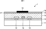
- FIG. 1 shows an example of a cross-sectional configuration of a TFT (Thin Film Transistor) array substrate used for a flat panel display or the like.
- TFT Thin Film Transistor
- a metal wiring 12 is formed on a glass substrate 11, and an insulating film 13 is formed so as to cover the entire surface of the glass substrate 11 and the metal wiring 12.
- a metal wiring 14 is formed on the insulating film 13, and an insulating film 15 is formed so as to cover the entire surface of the insulating film 13 and the metal wiring 14.
- a functional film 16 and a functional film 17 are formed on the insulating film 15.
- a transparent electrode 18 and a functional film 19 are formed on the functional film 16 and the functional film 17.
- the functional thin film 16 and the functional thin film 17 are color filters, and the functional thin film 19 is a black matrix.
- the functional film 19 is composed of a black matrix, it is difficult to obtain a clear image of the metal wiring 14 under the functional film 19 by using visible light as illumination light.
- the present invention has been made in view of such a situation, and obtains an image of an inner layer of an inspection object having a multilayer structure with good image quality, and as a result, improves the inspection accuracy of the inner layer. It is to make.
- An inspection apparatus includes an illumination wavelength changing unit that changes a wavelength of illumination light applied to an inspection object, and a second layer that is inspected through the first layer of the inspection object.
- An illumination wavelength setting unit that sets the wavelength of the illumination light using the illumination wavelength change unit based on the light transmission characteristics of the first layer, and an imaging control unit that controls the imaging of the image of the inspection object irradiated with the illumination light
- an inspection unit that inspects the second layer based on the image of the inspection object irradiated with the illumination light.
- the illumination wavelength changing unit is used based on the light transmission characteristics of the first layer.
- the wavelength of the illumination light is set, the photographing of the image of the inspection object irradiated with the illumination light is controlled, and the second layer is inspected based on the image of the inspection object irradiated with the illumination light.
- an image of the inner layer (second layer) of the inspection object having a multilayer structure can be acquired with good image quality.
- the illumination wavelength changing unit includes, for example, a wavelength selection filter including a plurality of filters having different wavelength characteristics, an AOTF (acousto-optic variable wavelength filter), and a device that switches a plurality of light sources having different wavelengths.
- the wavelength setting unit, the imaging control unit, and the inspection unit are configured by, for example, a computer or various control devices.
- the illumination wavelength setting unit uses the illumination wavelength changing unit to set the wavelength of the illumination light to a plurality of different values within a predetermined range.
- the unit is controlled to take images of the inspection object irradiated with the illumination light of each wavelength, and the inspection unit has a plurality of images of the inspection object irradiated with the illumination light of each wavelength. Based on the above, the second layer can be inspected.
- the illumination wavelength setting unit if a desired inspection result is not obtained based on an image of an inspection object irradiated with illumination light having a wavelength set based on the light transmission characteristics of the first layer, the illumination wavelength Using the changing unit, the wavelength of the illumination light is set to a plurality of different values within a predetermined range, and the imaging control unit is configured to capture an image of the inspection object irradiated with the illumination light of each wavelength. It is possible to cause the inspection unit to inspect the second layer based on a plurality of images of the inspection object irradiated with the illumination light of each wavelength.
- the inspection apparatus may further include a focus setting unit that sets a focus position when photographing the inspection object based on the depth of the second layer of the inspection object.
- This focus setting unit is constituted by, for example, a computer or various control devices.
- the focus setting unit sets the focus position to a plurality of different positions within a predetermined range. Control can be performed so as to capture an image of the inspection object, and the inspection unit can inspect the second layer based on a plurality of images of the inspection object captured at each focus position.
- the illumination wavelength changing unit can change the wavelength of the illumination light applied to the inspection object by changing the wavelength extracted from the light emitted from the predetermined light source.
- the illumination wavelength changing unit can change the wavelength of the illumination light applied to the inspection object by selecting a light source to be used from among a plurality of light sources that emit light having different wavelengths.
- an inspection apparatus including an illumination wavelength changing unit that changes the wavelength of illumination light applied to an inspection object inspects the second layer through the first layer of the inspection object.
- the wavelength of the illumination light is set using the illumination wavelength changing unit, and the photographing of the inspection object irradiated with the illumination light is controlled.
- a step of inspecting the second layer based on the image of the irradiated inspection object is included.
- the illumination wavelength changing unit is used based on the light transmission characteristics of the first layer.
- the wavelength of the illumination light is set, the photographing of the image of the inspection object irradiated with the illumination light is controlled, and the second layer is inspected based on the image of the inspection object irradiated with the illumination light.
- an image of the inner layer (second layer) of the inspection object having a multilayer structure can be acquired with good image quality.
- the illumination wavelength changing unit includes, for example, a wavelength selection filter including a plurality of filters having different wavelength characteristics, an AOTF (acousto-optic variable wavelength filter), and a device that switches a plurality of light sources having different wavelengths.
- a wavelength selection filter including a plurality of filters having different wavelength characteristics
- an AOTF acousto-optic variable wavelength filter
- the present invention it is possible to acquire an image of a layer inside an inspection object having a multilayer structure with good image quality. In addition, according to one aspect of the present invention, it is possible to improve the inspection accuracy of the layers inside the inspection object having a multilayer structure.
- Embodiment 2 modes for carrying out the present invention (hereinafter referred to as embodiments) will be described. The description will be given in the following order. 1. Embodiment 2. FIG. Modified example
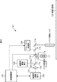
- FIG. 2 is a block diagram showing an embodiment of an inspection apparatus 101 to which the present invention is applied.
- the inspection apparatus 101 is an inspection apparatus that detects a defect in a circuit pattern of the inspection object 102 based on an image obtained by photographing the inspection object 102.
- the inspection apparatus 101 includes a light source 111, a lens 112, a wavelength selection filter 113, a half mirror 114, a dichroic mirror 115, a total reflection mirror 116, an objective lens 117, a half mirror 118, an imaging lens 119, an inspection imaging device 120, and an imaging.
- the lens 121, the observation imaging device 122, the inspection control unit 123, and the focus control unit 124 are configured.
- the light source 111 is constituted by, for example, a halogen lamp that emits infrared light in a wavelength range of a predetermined range.
- the illumination light emitted from the light source 111 is collimated by the lens 112 and then enters the wavelength selection filter 113.
- FIG. 3 shows a configuration example of the wavelength selection filter 113.
- the wavelength selection filter 113 includes four types of filters 151a to 151d.
- the filters 151a to 151d have different transmission wavelength bands. Further, the widths of the transmission wavelength bands of the filters 151a to 151d are almost equal and limited to a narrow range. Therefore, the illumination light extracted by passing through the filters 151a to 151d is almost similar to monochromatic light. Further, for example, the transmission wavelength bands of the filters 151 a to 151 d are set to be substantially equidistant within the wavelength band of the light source 111.
- the wavelength selection filter 113 can be physically moved in the direction of the arrow A under the control of the inspection control unit 123, and the filter installed on the optical path of the illumination light emitted from the light source 111 can be switched. it can. Thereby, the wavelength of the illumination light with which the inspection object 102 is irradiated is changed.
- filters 151a to 151d are simply referred to as filters 151.
- the number of filters 151 provided in the wavelength selection filter 113 is not limited to this example, and can be set to an arbitrary number.
- a part of the illumination light transmitted through any one of the filters 151 of the wavelength selection filter 113 is reflected by the half mirror 114 in the direction of the dichroic mirror 115, and the rest is transmitted through the half mirror 114.
- the illumination light reflected in the direction of the dichroic mirror 115 is transmitted through the dichroic mirror 115, reflected by the total reflection mirror 116, and then irradiated onto the inspection object 102 through the objective lens 117.
- Observation light from the inspection object 102 including reflected light of illumination light passes through the objective lens 117, is reflected by the total reflection mirror 116, is partially reflected by the dichroic mirror 115, and enters the focus control unit 124. The remaining light passes through the dichroic mirror 115.
- the observation light that has passed through the dichroic mirror 115 is partially reflected by the half mirror 114, and the rest passes through the half mirror 114.
- Part of the observation light that has passed through the half mirror 114 is reflected by the half mirror 118, and the rest passes through the half mirror 118.
- the observation light transmitted through the half mirror 118 is imaged on the imaging surface of the inspection image sensor 120 by the imaging lens 119.
- the inspection imaging device 120 takes an image of observation light, that is, an image of the inspection object 102, and controls the inspection of an image obtained as a result (hereinafter referred to as an inspection image). To the unit 123.
- observation imaging element 122 takes an image of observation light, that is, an image of the inspection object 102 under the control of a control unit (not shown), and an image obtained as a result (hereinafter referred to as an observation image). It is supplied to a monitor (not shown) and displayed on the monitor.
- the inspection control unit 123 is configured by, for example, a computer or various control devices.
- the inspection control unit 123 inspects the inspection object 102 based on the inspection image supplied from the inspection image sensor 120 and outputs the inspection result to the outside.
- the focus control unit 124 controls the focus position of the objective lens 117 by the autofocus function, or sets the focus position of the objective lens 117 to a designated position under the control of the inspection control unit 123.
- FIG. 4 is a block diagram illustrating an exemplary functional configuration of the inspection control unit 123.
- the inspection control unit 123 is configured to include an input unit 171, an inspection unit 172, an illumination wavelength setting unit 173, a focus setting unit 174, an imaging control unit 175, and an output unit 176.
- the input unit 171 includes various input devices. For example, various data such as characteristic data of the inspection object 102 and various commands to the inspection device 101 are input. The input unit 171 supplies the input data and command to the inspection unit 172.
- the inspection unit 172 supplies data included in the characteristic data of the inspection target unit 102 supplied from the input unit 171 to the illumination wavelength setting unit 173 and the focus setting unit 174 as necessary. Further, the inspection unit 172 gives various commands to the illumination wavelength setting unit 173, the imaging control unit 175, and the focus setting unit 174, and executes predetermined processing.
- the inspection unit 172 inspects the inspection object 102 based on the inspection image supplied from the inspection image sensor 120 via the imaging control unit 175. Then, the inspection unit 172 outputs the inspection result of the inspection object 102 to the outside via the output unit 176.
- the illumination wavelength setting unit 173 controls the wavelength selection filter 113 based on the command of the inspection unit 172, and sets the wavelength of illumination light irradiated on the inspection object 102.
- the focus setting unit 174 sets the focus position of the objective lens 117 by controlling the focus control unit 124 based on a command from the inspection unit 172.
- the imaging control unit 175 controls the imaging of the inspection image by the inspection image sensor 120 based on the instruction of the inspection unit 172. Further, the imaging control unit 175 acquires an inspection image from the inspection image sensor 120 and supplies the inspection image to the inspection unit 172.
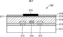
- the inspection object 102 has the same configuration as the TFT array substrate 1 used in the flat panel display of FIG. In the figure, the parts corresponding to those in FIG.
- a metal wiring 212 is formed on a glass substrate 211, and an insulating film 213 is formed so as to cover the entire surface of the glass substrate 211 and the metal wiring 212. Further, a metal wiring 214 is formed on the insulating film 213, and the insulating film 215 is formed so as to cover the entire surface of the insulating film 213 and the metal wiring 214. Furthermore, a functional film 216 and a functional film 217 made of, for example, a color filter are formed on the insulating film 215. Further, on the functional film 216 and the functional film 217, a transparent electrode 218 and a functional film 219 made of, for example, a color filter or a black matrix are formed.
- step S ⁇ b> 1 when the characteristic data of the inspection object 102 is input via the input unit 171, the inspection unit 172 acquires the characteristic data.
- step S1 if the characteristic data is not input, the process of step S1 is not performed.
- step S2 the inspection unit 172 determines whether or not the light transmission characteristics of the functional film 219 are known.
- the inspection unit 172 determines that the light transmission characteristics of the functional film 219 are known, and the process proceeds to step S3.
- the inspection apparatus 101 sets the wavelength of the illumination light based on the light transmission characteristics of the functional film 219.
- the inspection unit 172 supplies the light transmission characteristics of the functional film 219 to the illumination wavelength setting unit 173 and commands the setting of the wavelength of illumination light.
- the illumination wavelength setting unit 173 transmits light having a wavelength included in the transmission wavelength band of the functional film 219 (that is, light having a wavelength that passes through the functional film 219) from the filters 151 a to 151 d of the wavelength selection filter 113.
- the filter 151 to be selected is selected.
- the illumination wavelength setting unit 173 controls the position of the wavelength selection filter 113 so that the selected filter 151 is on the optical path of the illumination light.
- step S4 the inspection unit 172 determines whether or not the depth of the layer to be inspected is known.
- the inspection unit 172 knows the depth of the layer to be inspected. The process proceeds to step S5.
- step S5 the inspection apparatus 101 sets the focus position based on the depth of the layer to be inspected.
- the inspection unit 172 notifies the focus setting unit 174 of the depth of the metal wiring 214 to be inspected, and commands the setting of the focus position.
- the focus setting unit 174 instructs the focus control unit 124 to focus the objective lens 117 at a position deeper than the position set by normal autofocus (that is, the surface of the inspection object 102) by the depth of the metal wiring 214. Let the position be set. Thereby, the focus position is set on the surface of the metal wiring 214.
- step S6 the inspection apparatus 101 acquires an inspection image.
- the inspection unit 172 instructs the imaging control unit 175 to acquire an inspection image.
- the imaging control unit 175 controls the inspection image sensor 120 to image the inspection object 102 and acquires an inspection image obtained as a result.
- the imaging control unit 175 supplies the acquired inspection image to the inspection unit 172.
- the inspection image acquired at this time is taken with illumination light having a wavelength set based on the light transmission characteristics of the functional film 219 and with the focus position set on the surface of the metal wiring 214. is there.
- step S4 the inspection unit 172 does not include the depth of the layer to be inspected (in this case, the metal wiring 214) from the surface of the inspection object 102 in the acquired characteristic data, or the characteristic When the data cannot be acquired, it is determined that the depth of the layer to be inspected is unknown, and the process proceeds to step S7.
- the depth of the layer to be inspected in this case, the metal wiring 214.
- step S7 the inspection apparatus 101 sets the focus position on the surface of the inspection object 102.
- the inspection unit 172 instructs the focus setting unit 174 to set the focus position on the surface of the inspection object 102.
- the focus setting unit 174 instructs the focus control unit 124 to set the focus position of the objective lens 117 at a position set by normal autofocus (that is, the surface of the inspection object 102 (functional film 219)). .
- step S8 an inspection image is acquired in the same manner as in step S6.
- step S9 the inspection unit 172 determines whether or not inspection images have been acquired for all focus positions. If it is determined that the inspection images have not been acquired for all the focus positions, the process proceeds to step S10.
- step S10 the inspection apparatus 101 shifts the focus position. Specifically, the inspection unit 172 instructs the focus setting unit 174 to set the focus position to a position deep by a predetermined distance from the current position. The focus setting unit 174 instructs the focus control unit 124 to shift the focus position of the objective lens 117 to a deep position by a predetermined distance from the current position.
- step S9 the process returns to step S8, and the processes of steps 8 to S10 are repeatedly executed until it is determined in step S9 that the inspection images have been acquired for all the focus positions.
- the inspection object 102 is photographed while shifting the focus position by a predetermined distance from the surface of the inspection object 102 to a predetermined depth, and an inspection image at each focus position is acquired.
- the focus position setting range and the shift amount per time can be set by the user, for example.
- step S9 if it is determined in step S9 that inspection images have been acquired for all focus positions, the process proceeds to step S11.
- step S11 the inspection unit 172 executes an inspection processing calculation.
- the inspection unit 172 performs pattern matching on all acquired inspection images with an image including a normal pattern of the metal wiring 214 and tries to detect a defect in the metal wiring 214 to be inspected.
- the method used for the inspection processing calculation is not limited to pattern matching, and any method using an inspection image can be adopted.
- step S12 the inspection unit 172 determines whether a defect has been detected based on the result of the inspection processing calculation. If it is determined that a defect has been detected, the process proceeds to step S13.
- step S13 the inspection unit 172 outputs the defect detection result via the output unit 176.
- step S12 determines whether defect has been detected. If it is determined in step S12 that no defect has been detected, the process proceeds to step S14.
- the defect detection fails, in addition to the case where the defect cannot actually be detected as a result of pattern matching, for example, the image quality of the inspection image is poor and a sufficient amount of feature points cannot be extracted. This includes cases where pattern matching fails due to factors such as the above.
- step S ⁇ b> 2 if the acquired characteristic data does not include the light transmission characteristics of the functional film 219 or if the characteristic data cannot be acquired, the inspection unit 172 determines that the light transmission characteristics of the functional film 219 are the same. It determines with it being unknown, and a process progresses to step S14.
- step S14 the inspection apparatus 101 sets the wavelength of the illumination light to an initial value.
- the inspection unit 172 instructs the illumination wavelength setting unit 173 to set the wavelength of the illumination light to an initial value.
- the illumination wavelength setting unit 173 selects the filter 151 to be used first in accordance with a preset order.
- the illumination wavelength setting unit 173 controls the position of the wavelength selection filter 113 so that the selected filter 151 is on the optical path of the illumination light.
- step S15 similarly to the process of step S4, it is determined whether or not the depth of the layer to be inspected is known, and if it is determined that the depth of the layer to be inspected is known, the process Advances to step S16.
- step S16 as in the process of step S5, the focus position is set based on the depth of the layer to be inspected.
- step S16 If the focus position is set based on the depth of the layer to be inspected in step S5, the process in step S16 can be omitted.
- step S17 an inspection image is acquired in the same manner as in step S6.
- step S18 the inspection unit 172 determines whether or not inspection images have been acquired for all wavelength ranges of illumination light. When there is a filter that has not yet been used for acquiring the inspection image among the filters 151a to 151d of the wavelength selection filter 113, the inspection unit 172 has not acquired the inspection image for all the wavelength ranges of the illumination light. Determination is made, and the process proceeds to step S19.
- step S19 the inspection apparatus 101 shifts the wavelength of the illumination light.
- the inspection unit 172 instructs the illumination wavelength setting unit 173 to shift the wavelength of the illumination light.
- the illumination wavelength setting unit 173 selects the filter 151 to be used next in accordance with a preset order.
- the illumination wavelength setting unit 173 controls the position of the wavelength selection filter 113 so that the selected filter 151 is on the optical path of the illumination light.
- step S18 the process returns to step S17, and the processes of steps S17 to S19 are repeatedly executed until it is determined in step S18 that the inspection images have been acquired for all the wavelength ranges of the illumination light. Accordingly, the inspection object 102 is photographed using the filters 151a to 151d in a state where illumination lights having different wavelengths are irradiated, and a plurality of inspection images corresponding to the respective wavelengths are acquired.
- the illumination light having the wavelength is processed in steps S17 to S19. It is possible not to acquire the used inspection image again.
- step S18 when there is no filter that is not used for acquiring the inspection image among the filters 151a to 151d of the wavelength selection filter 113, the inspection unit 172 displays the inspection image for all the wavelength ranges of the illumination light. It determines with having acquired, and a process progresses to step S26.
- step S15 If it is determined in step S15 that the depth of the layer to be inspected is unknown, the process proceeds to step S20.
- step S20 the focus position is set on the surface of the inspection object 102 as in the process of step S7.
- step S21 an inspection image is acquired in the same manner as in step S8.
- step S22 as in the process of step S9, it is determined whether or not inspection images have been acquired for all focus positions. If it is determined that inspection images have not yet been acquired for all focus positions, The process proceeds to step S23.
- step S23 the focus position is shifted as in step S10.
- step S21 Thereafter, the process returns to step S21, and the processes of steps S21 to S23 are repeatedly executed until it is determined in step S22 that inspection images have been acquired for all focus positions.
- step S22 determines whether inspection images have been acquired for all focus positions. If it is determined in step S22 that inspection images have been acquired for all focus positions, the process proceeds to step S24.
- step S24 similarly to the processing in step S18, it is determined whether or not the inspection image has been acquired for all the wavelength ranges of the illumination light, and the inspection image is still acquired for all the wavelength ranges of the illumination light. If it is determined that it is not, the process proceeds to step S25.
- step S25 the wavelength of the illumination light is shifted as in the process of step S19.
- step S24 the process returns to step S20, and the processes of steps S20 to S25 are repeatedly executed until it is determined in step S24 that the inspection images have been acquired for all the wavelength ranges of the illumination light.
- inspection images are acquired for all combinations of settable wavelengths of illumination light and focus positions.
- step S24 if it is determined in step S24 that inspection images have been acquired for all wavelength ranges of illumination light, the process proceeds to step S26.
- step S26 the inspection processing calculation is executed in the same manner as in step S11.
- the inspection processing calculation may be individually performed on the plurality of acquired inspection images, or a plurality of inspection images captured using illumination light having different wavelengths at the same focus position.
- the inspection processing calculation may be executed on the synthesized image. Or you may make it perform a test
- step S27 as in the process of step S12, it is determined whether or not a defect has been detected. If it is determined that a defect has been detected, the process proceeds to step S28.
- step S28 as in the process of step S13, the defect detection result is output, and the inspection process ends.
- step S27 determines whether defect has been detected. If it is determined in step S27 that no defect has been detected, the process proceeds to step S29.
- step S29 the inspection unit 172 outputs the defect detection NG via the output unit 176. That is, the inspection unit 172 notifies the outside that a defect has not been detected.
- the wavelength of the illumination light is set based on the light transmission characteristics, so that the image of the metal wiring 214 can be quickly and easily obtained with good image quality. Can be acquired. As a result, the inspection accuracy of the metal wiring 214 can be improved and the inspection time can be shortened.
- the illumination light irradiated to the test object 102 becomes light close to monochromatic light, for example, compared with the case where illumination light having a wide wavelength band of 100 nm or more is used, generation of noise is suppressed, and the inspection image is displayed. Image quality can be improved.
- the defect of the metal wiring 214 cannot be detected with the wavelength of the illumination light set based on the light transmission characteristics of the functional film 219, it corresponds to each wavelength while shifting the wavelength of the illumination light within a predetermined range.
- a plurality of inspection images to be acquired are acquired, and an inspection is executed based on the acquired plurality of inspection images.
- the inspection of the metal wiring 214 is performed.
- an inspection image suitable for the case can be acquired.
- the inspection accuracy of the metal wiring 214 can be improved and the inspection time can be shortened.
- the focus position of the objective lens 117 is set based on the depth, so that an image of the metal wiring 214 can be obtained quickly and easily with good image quality. Can do. As a result, the inspection accuracy of the metal wiring 214 can be improved and the inspection time can be shortened.
- a plurality of inspection images at each focus position are acquired while shifting the focus position within a predetermined range, and an inspection is performed based on the acquired plurality of inspection images. Executed. This increases the possibility that an inspection image suitable for the inspection of the metal wiring 214 can be acquired. As a result, the inspection accuracy of the metal wiring 214 can be improved and the inspection time can be shortened.
- Modification 1 For example, as a means or method for changing the wavelength of illumination light, in addition to switching the plurality of filters described above, for example, extraction is performed using a filter having a variable transmission wavelength band such as an AOTF (acousto-optic variable wavelength filter). You may enable it to change the wavelength of the illumination light to perform continuously. Alternatively, a plurality of light sources having different wavelengths may be provided and a light source to be used may be selected.
- AOTF acousto-optic variable wavelength filter
- the wavelengths of the illumination light are set in the order closer to the wavelength. Also good. Thereby, it is possible to perform an inspection from an inspection image that is more likely to be inspected, and to reduce the number of inspection images to be acquired.
- the wavelength of illumination light is set based on the light transmission characteristics of only one of the layers above the layer to be inspected. Based on the above, the wavelength of the illumination light may be set. For example, in the inspection object 102 in FIG. 7, the wavelength of illumination light may be set based on the light transmission characteristics of the functional film 216, the functional film 217, and the functional film 219.
- foreign matter defects and contaminants can be easily detected by detecting a spectrum other than the substance originally used as the material from the spectrum of the inspection object detected by irradiating with illumination light of a plurality of wavelengths as described above. It can be carried out.
- the present invention can be applied to a case where an inspection object having a multilayer structure other than the TFT array substrate described above is inspected.
- the present invention can also be applied to inspections other than detection of substrate pattern defects. That is, the present invention inspects an inner layer based on an image obtained by photographing an inner layer of a multilayer structure inspection object, or inspects an inspection object based on a spectrum of the multilayer structure inspection object. It can be applied when doing.
- the series of processes of the inspection control unit 123 described above can be executed by hardware or can be executed by software.
- a program constituting the software is installed in the computer.
- the computer includes, for example, a general-purpose personal computer capable of executing various functions by installing various programs by installing a computer incorporated in dedicated hardware.
- the program executed by the computer may be a program that is processed in time series in the order described in this specification, or in parallel or at a necessary timing such as when a call is made. It may be a program for processing.
Landscapes
- Physics & Mathematics (AREA)
- Health & Medical Sciences (AREA)
- Life Sciences & Earth Sciences (AREA)
- Chemical & Material Sciences (AREA)
- Analytical Chemistry (AREA)
- Biochemistry (AREA)
- General Health & Medical Sciences (AREA)
- General Physics & Mathematics (AREA)
- Immunology (AREA)
- Pathology (AREA)
- Investigating Materials By The Use Of Optical Means Adapted For Particular Applications (AREA)
- Investigating Or Analysing Materials By Optical Means (AREA)
Abstract
多層構造の検査対象物の内部の層の画像を良好な画質で取得し、その結果、内部の層の検査精度を向上させる。波長選択フィルタ113は、検査対象物に照射する照明光の波長を変更する。照明波長設定部173は、検査対象物の第1の層を通して第2の層の検査を行う場合に、第1の層の透光特性に基づいて、波長選択フィルタ113を用いて照明光の波長を設定する。撮影制御部175は、検査用撮像素子120を制御して、照明光が照射された検査対象物を撮影させる。検査部172は、撮影の結果得られた検査画像に基づいて、第2の層の検査を行う。本発明は、例えば、TFTアレイ基板の検査装置に適用できる。
Description
本発明は、検査装置および検査方法に関し、特に、多層構造の検査対象物の検査を行う場合に用いて好適な検査装置および検査方法に関する。
図1は、フラットパネルディスプレイ等に用いられるTFT(Thin Film Transistor)アレイ基板の断面の構成の一例を示している。
このTFTアレイ基板1は、ガラス基板11の上に金属配線12が形成され、ガラス基板11および金属配線12の表面全体を覆うように絶縁膜13が形成されている。また、絶縁膜13の上に金属配線14が形成され、絶縁膜13および金属配線14の表面全体を覆うように絶縁膜15が形成されている。さらに、絶縁膜15の上に、機能性膜16および機能性膜17が形成されている。また、機能性膜16および機能性膜17の上に、透明電極18および機能性膜19が形成されている。一例として、機能性薄膜16および機能性薄膜17は、カラーフィルタであり、機能性薄膜19はブラックマトリクスである。
ここで、金属配線14の欠陥を検出するための検査を行う場合について検討する。なお、以下、説明を簡単にするために、特に言及する場合を除いて、機能性膜19の特性のみを考慮し、他の層の特性は考慮しないものとする。
例えば、機能性膜19が、ブラックマトリックスにより構成される場合、可視光を照明光として用いたのでは、機能性膜19の下にある金属配線14の鮮明な画像を得ることが難しい。
そこで、例えば、機能性膜19を透過する赤外光を照明光として用いることが考えられる(例えば、特許文献1参照)。
しかしながら、波長帯域が狭いほぼ単色の赤外光源を用いた場合、対応可能な機能性膜19の種類が限定されてしまう。そのため、例えば、仕様変更等により機能性膜19の代わりに透過特性が異なる別の機能性膜がTFTアレイ基板1に用いられた場合、金属配線14の鮮明な画像を得ることが困難になる。これは、例えば、TFTアレイ基板1とは機能性膜の透過特性が異なるTFTアレイ基板を検査する場合も同様である。
一方、透過特性が異なる機能性膜に対応できるように、特許文献1に記載の発明のように、波長帯域が広い(例えば、100nm以上)赤外光源を用いることが考えられる。しかしながら、機能性膜19の波長特性は、照明光の波長により様々に変化するため、照明光の波長帯域が広くなるほど、ノイズが発生しやすくなり、検査画像の画質が低下する恐れがある。これは、機能性膜19以外の他の層についても同様である。
本発明は、このような状況に鑑みてなされたものであり、多層構造の検査対象物の内部の層の画像を良好な画質で取得し、その結果、内部の層の検査精度を向上させるようにするものである。
本発明の一側面の検査装置は、検査対象物に照射する照明光の波長を変更する照明波長変更部と、検査対象物の第1の層を通して第2の層の検査を行う場合に、第1の層の透光特性に基づいて、照明波長変更部を用いて照明光の波長を設定する照明波長設定部と、照明光が照射された検査対象物の画像の撮影を制御する撮影制御部と、照明光が照射された検査対象物の画像に基づいて、第2の層の検査を行う検査部とを備える。
本発明の一側面の検査装置においては、検査対象物の第1の層を通して第2の層の検査を行う場合に、第1の層の透光特性に基づいて、照明波長変更部を用いて照明光の波長が設定され、照明光が照射された検査対象物の画像の撮影が制御され、照明光が照射された検査対象物の画像に基づいて、第2の層の検査が行われる。
従って、多層構造の検査対象物の内部の層(第2の層)の画像を良好な画質で取得することができる。その結果、多層構造の検査対象物の内部の層の検査精度を向上させることができる。
この照明波長変更部は、例えば、波長特性が異なる複数のフィルタを備える波長選択フィルタ、AOTF(音響光学可変波長フィルタ)、波長の異なる複数の光源を切り替える装置により構成される。この波長設定部、撮影制御部、検査部は、例えば、コンピュータ、または、各種の制御装置により構成される。
この照明波長設定部には、第1の層の透光特性が未知である場合、照明波長変更部を用いて照明光の波長を所定の範囲内で異なる複数の値に設定させ、この撮影制御部には、各波長の照明光が照射された検査対象物の画像をそれぞれ撮影するように制御させ、この検査部には、各波長の照明光がそれぞれ照射された検査対象物の複数の画像に基づいて、第2の層の検査を行わせることができる。
これにより、第1の層の透光特性が未知の場合にも、多層構造の検査対象物の内部の層(第2の層)の画像を良好な画質で取得することができる。その結果、多層構造の検査対象物の内部の層の検査精度を向上させることができる。
この照明波長設定部には、第1の層の透光特性に基づいて設定した波長の照明光が照射された検査対象物の画像に基づいて所望の検査結果が得られなかった場合、照明波長変更部を用いて照明光の波長を所定の範囲内で異なる複数の値に設定させ、この撮影制御部には、各波長の照明光が照射された検査対象物の画像をそれぞれ撮影するように制御させ、この検査部には、各波長の照明光がそれぞれ照射された検査対象物の複数の画像に基づいて、第2の層の検査を行わせることができる。
これにより、多層構造の検査対象物の内部の層(第2の層)の画像を良好な画質で取得することができる可能性が高くなる。その結果、多層構造の検査対象物の内部の層の検査精度を向上させることができる。
この検査装置には、検査対象物の第2の層の深さに基づいて、検査対象物を撮影する際のフォーカス位置を設定するフォーカス設定部をさらに設けることができる。
これにより、多層構造の検査対象物の内部の層(第2の層)の画像をより良好な画質で取得することができる。その結果、多層構造の検査対象物の内部の層の検査精度を向上させることができる。
このフォーカス設定部は、例えば、コンピュータ、または、各種の制御装置により構成される。
このフォーカス設定部には、検査対象物の第2の層の深さが未知の場合、フォーカス位置を所定の範囲内で異なる複数の位置に設定させ、この撮影制御部には、各フォーカス位置において検査対象物の画像を撮影するように制御させ、この検査部には、各フォーカス位置において撮影された検査対象物の複数の画像に基づいて、第2の層の検査を行わせることができる。
これにより、多層構造の検査対象物の内部の層(第2の層)の深さが未知の場合にも、内部の層の画像を良好な画質で取得することができる。その結果、多層構造の検査対象物の内部の層の検査精度を向上させることができる。
この照明波長変更部は、所定の光源から発せられる光から抽出する波長を変更することにより、検査対象物に照射する照明光の波長を変更させることができる。
この照明波長変更部には、それぞれ異なる波長の光を発する複数の光源の中から使用する光源を選択することにより、検査対象物に照射する照明光の波長を変更させることができる。
本発明の一側面の検査方法は、検査対象物に照射する照明光の波長を変更する照明波長変更部を備える検査装置が、検査対象物の第1の層を通して第2の層の検査を行う場合に、第1の層の透光特性に基づいて、照明波長変更部を用いて照明光の波長を設定し、照明光が照射された検査対象物の画像の撮影を制御し、照明光が照射された検査対象物の画像に基づいて、第2の層の検査を行うステップを含む。
本発明の一側面の検査方法においては、検査対象物の第1の層を通して第2の層の検査を行う場合に、第1の層の透光特性に基づいて、照明波長変更部を用いて照明光の波長が設定され、照明光が照射された検査対象物の画像の撮影が制御され、照明光が照射された検査対象物の画像に基づいて、第2の層の検査が行われる。
従って、多層構造の検査対象物の内部の層(第2の層)の画像を良好な画質で取得することができる。その結果、多層構造の検査対象物の内部の層の検査精度を向上させることができる。
この照明波長変更部は、例えば、波長特性が異なる複数のフィルタを備える波長選択フィルタ、AOTF(音響光学可変波長フィルタ)、波長の異なる複数の光源を切り替える装置により構成される。
本発明の一側面によれば、多層構造の検査対象物の内部の層の画像を良好な画質で取得することができる。また、本発明の一側面によれば、多層構造の検査対象物の内部の層の検査精度を向上させることができる。
以下、本発明を実施するための形態(以下、実施の形態という)について説明する。なお、説明は以下の順序で行う。
1.実施の形態
2.変形例
1.実施の形態
2.変形例
<1.実施の形態>
[検査装置101の構成例]
図2は、本発明を適用した検査装置101の一実施の形態を示すブロック図である。
[検査装置101の構成例]
図2は、本発明を適用した検査装置101の一実施の形態を示すブロック図である。
検査装置101は、検査対象物102を撮影することにより得られる画像に基づいて、検査対象物102の回路パターンの欠陥の検出等を行う検査装置である。
検査装置101は、光源111、レンズ112、波長選択フィルタ113、ハーフミラー114、ダイクロイックミラー115、全反射ミラー116、対物レンズ117、ハーフミラー118、結像レンズ119、検査用撮像素子120、結像レンズ121、観察用撮像素子122、検査制御部123、および、フォーカス制御部124を含むように構成される。
光源111は、例えば、所定の範囲の波長帯域の赤外光を発するハロゲンランプにより構成される。光源111から発せられた照明光は、レンズ112よりコリメートされた後、波長選択フィルタ113に入射する。
図3は、波長選択フィルタ113の構成例を示している。
波長選択フィルタ113は、フィルタ151a乃至151dの4種類のフィルタを備えている。フィルタ151a乃至151dは、それぞれ異なる透過波長帯域を有している。また、フィルタ151a乃至151dの透過波長帯域の幅ほぼ等しく、かつ狭い範囲に限定されている。従って、フィルタ151a乃至151dをそれぞれ透過することにより抽出される照明光は、ほぼ単色光に近い光となる。さらに、例えば、フィルタ151a乃至151dの透過波長帯域は、光源111の波長帯域内において、ほぼ等間隔になるように設定される。
また、波長選択フィルタ113は、検査制御部123の制御の下に、矢印Aの方向に物理的に移動させることができ、光源111から発せられる照明光の光路上に設置するフィルタを切り替えることができる。これにより、検査対象物102に照射する照明光の波長が変更される。
なお、以下、フィルタ151a乃至151dを個々に区別する必要がない場合、単にフィルタ151と称する。
また、波長選択フィルタ113に設けられるフィルタ151の数は、この例に限定されるものではなく、任意の数に設定することが可能である。
図2に戻り、波長選択フィルタ113のいずれかのフィルタ151を透過した照明光は、ハーフミラー114により一部がダイクロイックミラー115の方向に反射され、残りがハーフミラー114を透過する。ダイクロイックミラー115の方向に反射された照明光は、ダイクロイックミラー115を透過し、全反射ミラー116により反射された後、対物レンズ117を介して、検査対象物102に照射される。
照明光の反射光等を含む検査対象物102からの観察光は、対物レンズ117を透過し、全反射ミラー116により反射され、ダイクロイックミラー115により一部が反射されて、フォーカス制御部124に入射し、残りがダイクロイックミラー115を透過する。
ダイクロイックミラー115を透過した観察光は、ハーフミラー114により一部が反射され、残りがハーフミラー114を透過する。ハーフミラー114を透過した観察光は、ハーフミラー118により一部が反射され、残りがハーフミラー118を透過する。
ハーフミラー118を透過した観察光は、結像レンズ119により、検査用撮像素子120の結像面において結像する。検査用撮像素子120は、検査制御部123の制御の下に、観察光による像、すなわち、検査対象物102の像を撮影し、その結果得られる画像(以下、検査画像と称する)を検査制御部123に供給する。
一方、ハーフミラー118により反射された観察光は、結像レンズ121により、観察用撮像素子122の結像面において結像する。観察用撮像素子122は、制御部(不図示)の制御の下に、観察光による像、すなわち、検査対象物102の像を撮影し、その結果得られる画像(以下、観察画像と称する)をモニタ(不図示)に供給し、モニタに表示させる。
検査制御部123は、例えば、コンピュータ、あるいは、各種の制御装置により構成される。検査制御部123は、検査用撮像素子120から供給される検査画像に基づいて、検査対象物102の検査を行い、検査結果を外部に出力する。
フォーカス制御部124は、オートフォーカス機能により対物レンズ117のフォーカス位置を制御したり、検査制御部123の制御の下に、対物レンズ117のフォーカス位置を指定された位置に設定したりする。
[検査制御部123の構成例]
図4は、検査制御部123の機能の構成例を示すブロック図である。
図4は、検査制御部123の機能の構成例を示すブロック図である。
検査制御部123は、入力部171、検査部172、照明波長設定部173、フォーカス設定部174、撮影制御部175、および、出力部176を含むように構成される。
入力部171は、各種の入力装置により構成され、例えば、検査対象物102の特性データ等の各種のデータや、検査装置101に対する各種の指令が入力される。入力部171は、入力されたデータおよび指令を検査部172に供給する。
検査部172は、入力部171から供給される検査対象部102の特性データに含まれるデータを、必要に応じて照明波長設定部173およびフォーカス設定部174に供給する。また、検査部172は、照明波長設定部173、撮影制御部175、および、フォーカス設定部174に各種の指令を与え、所定の処理を実行させる。
さらに、検査部172は、撮影制御部175を介して、検査用撮像素子120から供給される検査画像に基づいて、検査対象物102の検査を行う。そして、検査部172は、検査対象物102の検査結果を、出力部176を介して外部に出力する。
照明波長設定部173は、検査部172の指令の基に、波長選択フィルタ113を制御して、検査対象物102に照射される照明光の波長を設定する。
フォーカス設定部174は、検査部172の指令の基に、フォーカス制御部124を制御して、対物レンズ117のフォーカス位置を設定する。
撮影制御部175は、検査部172の指令の基に、検査用撮像素子120による検査画像の撮影を制御する。また、撮影制御部175は、検査用撮像素子120から検査画像を取得し、検査部172に供給する。
[検査処理]
次に、図5および図6のフローチャートを参照して、検査装置101により実行される検査処理について説明する。
次に、図5および図6のフローチャートを参照して、検査装置101により実行される検査処理について説明する。
なお、以下、検査対象物102が図7に示される構成を有しており、金属配線214の欠陥の検出を行う場合を具体例に挙げて説明する。
図7の例において、検査対象物102は、図1のフラットパネルディスプレイ等に用いられるTFTアレイ基板1と同様の構成を有している。なお、図中、図1と対応する部分には、下二桁が同じ符号を付している。
具体的には、検査対象物102は、ガラス基板211の上に金属配線212が形成され、ガラス基板211および金属配線212の表面全体を覆うように絶縁膜213が形成されている。また、絶縁膜213の上に金属配線214が形成され、絶縁膜213および金属配線214の表面全体を覆うように絶縁膜215が形成されている。さらに、絶縁膜215の上に、例えばカラーフィルタなどにより構成される機能性膜216および機能性膜217が形成されている。また、機能性膜216および機能性膜217の上に、透明電極218、および、例えばカラーフィルタまたはブラックマトリックスなどにより構成される機能性膜219が形成されている。
なお、以下、説明を簡単にするために、特に言及する場合を除いて、機能性膜219の特性のみを考慮し、他の層の特性は考慮しないものとする。
ステップS1において、検査部172は、入力部171を介して検査対象物102の特性データが入力された場合、その特性データを取得する。
なお、特性データが入力されなかった場合、ステップS1の処理は行われない。
ステップS2において、検査部172は、機能性膜219の透光特性が既知であるか否かを判定する。検査部172は、取得した特性データに機能性膜219の透光特性が含まれる場合、機能性膜219の透光特性が既知であると判定し、処理はステップS3に進む。
ステップS3において、検査装置101は、機能性膜219の透光特性に基づいて、照明光の波長を設定する。具体的には、検査部172は、機能性膜219の透光特性を照明波長設定部173に供給するとともに、照明光の波長の設定を指令する。照明波長設定部173は、波長選択フィルタ113のフィルタ151a乃至151dの中から、機能性膜219の透過波長帯域に含まれる波長の光(すなわち、機能性膜219を透過する波長の光)を透過するフィルタ151を選択する。そして、照明波長設定部173は、選択したフィルタ151が照明光の光路上にくるように、波長選択フィルタ113の位置を制御する。
ステップS4において、検査部172は、検査対象となる層の深さが既知であるか否かを判定する。検査部172は、取得した特性データに検査対象となる層(いまの場合、金属配線214)の検査対象物102の表面からの深さが含まれる場合、検査対象となる層の深さが既知であると判定し、処理はステップS5に進む。
ステップS5において、検査装置101は、検査対象となる層の深さに基づいて、フォーカス位置を設定する。具体的には、検査部172は、検査対象となる金属配線214の深さをフォーカス設定部174に通知するとともに、フォーカス位置の設定を指令する。フォーカス設定部174は、フォーカス制御部124に指令して、通常のオートフォーカスで設定される位置(すなわち、検査対象物102の表面)より金属配線214の深さだけ深い位置に対物レンズ117のフォーカス位置を設定させる。これにより、金属配線214の表面にフォーカス位置が設定される。
ステップS6において、検査装置101は、検査画像を取得する。具体的には、検査部172は、検査画像の取得を撮影制御部175に指令する。撮影制御部175は、検査用撮像素子120を制御して、検査対象物102を撮影させ、その結果得られた検査画像を取得する。撮影制御部175は、取得した検査画像を検査部172に供給する。
このとき取得される検査画像は、機能性膜219の透光特性に基づいて設定された波長の照明光が照射され、金属配線214の表面にフォーカス位置が設定された状態で撮影されたものである。
その後、処理はステップS11に進む。
一方、ステップS4において、検査部172は、取得した特性データに検査対象となる層(いまの場合、金属配線214)の検査対象物102の表面からの深さが含まれない場合、または、特性データを取得できなかった場合、検査対象となる層の深さが未知であると判定し、処理はステップS7に進む。
ステップS7において、検査装置101は、フォーカス位置を検査対象物102の表面に設定する。具体的には、検査部172は、検査対象物102の表面にフォーカス位置を設定するようにフォーカス設定部174に指令する。フォーカス設定部174は、フォーカス制御部124に指令して、通常のオートフォーカスで設定される位置(すなわち、検査対象物102(機能性膜219)の表面)に対物レンズ117のフォーカス位置を設定させる。
ステップS8において、ステップS6の処理と同様に、検査画像が取得される。
ステップS9において、検査部172は、全てのフォーカス位置について検査画像を取得したか否かを判定する。まだ全てのフォーカス位置について、検査画像を取得していないと判定された場合、処理はステップS10に進む。
ステップS10において、検査装置101は、フォーカス位置をシフトする。具体的には、検査部172は、フォーカス位置を現在の位置から所定の距離だけ深い位置に設定するようにフォーカス設定部174に指令する。フォーカス設定部174は、フォーカス制御部124に指令して、対物レンズ117のフォーカス位置を現在の位置から所定の距離だけ深い位置にシフトさせる。
その後、処理はステップS8に戻り、ステップS9において、全てのフォーカス位置について検査画像を取得したと判定されるまで、ステップ8乃至S10の処理が繰り返し実行される。これにより、検査対象物102の表面から所定の深さまで、フォーカス位置を所定の距離ずつシフトしながら、検査対象物102が撮影され、各フォーカス位置での検査画像が取得される。
なお、フォーカス位置の設定範囲、および、1回あたりのシフト量は、例えば、ユーザが設定することができる。
一方、ステップS9において、全てのフォーカス位置について検査画像を取得したと判定された場合、処理はステップS11に進む。
ステップS11において、検査部172は、検査処理演算を実行する。例えば、検査部172は、取得した全ての検査画像について、正常な金属配線214のパターンを含む画像とのパターンマッチングを行い、検査対象となる金属配線214の欠陥の検出を試みる。
なお、検査処理演算に用いる手法には、パターンマッチングに限定されるものではなく、検査画像を用いる任意の手法を採用することができる。
ステップS12において、検査部172は、検査処理演算の結果に基づいて、欠陥を検出できたか否かを判定する。欠陥を検出できたと判定された場合、処理はステップS13に進む。
ステップS13において、検査部172は、出力部176を介して、欠陥の検出結果を出力する。
その後、検査処理は終了する。
一方、ステップS12において、欠陥を検出できなかったと判定された場合、処理はステップS14に進む。
なお、欠陥の検出を失敗する場合の例としては、パターンマッチングの結果、実際に欠陥を検出できなかった場合の他、例えば、検査画像の画質が悪くて、十分な量の特徴点が抽出できない等の要因により、パターンマッチングに失敗した場合等も含む。
また、ステップS2において、検査部172は、取得した特性データに機能性膜219の透光特性が含まれない場合、または、特性データを取得できなかった場合、機能性膜219の透光特性が未知であると判定し、処理はステップS14に進む。
ステップS14において、検査装置101は、照明光の波長を初期値に設定する。具体的には、検査部172は、照明光の波長を初期値に設定するように照明波長設定部173に指令する。照明波長設定部173は、例えば、予め設定されている順番に従って、最初に使用するフィルタ151を選択する。そして、照明波長設定部173は、選択したフィルタ151が照明光の光路上にくるように、波長選択フィルタ113の位置を制御する。
ステップS15において、ステップS4の処理と同様に、検査対象となる層の深さが既知であるか否かが判定され、検査対象となる層の深さが既知であると判定された場合、処理はステップS16に進む。
ステップS16において、ステップS5の処理と同様に、検査対象となる層の深さに基づいて、フォーカス位置が設定される。
なお、先にステップS5において、検査対象となる層の深さに基づいて、フォーカス位置が設定されている場合、このステップS16の処理は省略することができる。
ステップS17において、ステップS6の処理と同様に、検査画像が取得される。
ステップS18において、検査部172は、照明光の全ての波長の範囲について、検査画像を取得したか否かを判定する。検査部172は、波長選択フィルタ113のフィルタ151a乃至151dのうち、まだ検査画像の取得に使用していないフィルタがある場合、照明光の全ての波長の範囲について、検査画像を取得していないと判定し、処理はステップS19に進む。
ステップS19において、検査装置101は、照明光の波長をシフトする。具体的には、検査部172は、照明光の波長をシフトするように照明波長設定部173に指令する。照明波長設定部173は、例えば、予め設定されている順番に従って、次に使用するフィルタ151を選択する。そして、照明波長設定部173は、選択したフィルタ151が照明光の光路上にくるように、波長選択フィルタ113の位置を制御する。
その後、処理はステップS17に戻り、ステップS18において、照明光の全ての波長の範囲について、検査画像を取得したと判定されるまで、ステップS17乃至S19の処理が繰り返し実行される。これにより、フィルタ151a乃至151dをそれぞれ用いて、それぞれ異なる波長の照明光が照射された状態で検査対象物102が撮影され、各波長に対応する複数の検査画像が取得される。
なお、先にステップS6の処理で、機能性膜219の透光特性に基づく波長の照明光を用いて検査画像を取得済みである場合、ステップS17乃至S19の処理で、その波長の照明光を用いた検査画像を、改めて取得しないようにすることが可能である。
一方、ステップS18において、検査部172は、波長選択フィルタ113のフィルタ151a乃至151dのうち、検査画像の取得に使用していないフィルタがない場合、照明光の全ての波長の範囲について、検査画像を取得したと判定し、処理はステップS26に進む。
また、ステップS15において、検査対象となる層の深さが未知である判定された場合、処理はステップS20に進む。
ステップS20において、ステップS7の処理と同様に、フォーカス位置が検査対象物102の表面に設定される。
ステップS21において、ステップS8の処理と同様に、検査画像が取得される。
ステップS22において、ステップS9の処理と同様に、全てのフォーカス位置について、検査画像を取得したか否かが判定され、まだ全てのフォーカス位置について、検査画像を取得していないと判定された場合、処理はステップS23に進む。
ステップS23において、ステップS10の処理と同様に、フォーカス位置がシフトされる。
その後、処理はステップS21に戻り、ステップS22において、全てのフォーカス位置について、検査画像を取得したと判定されるまで、ステップS21乃至S23の処理が繰り返し実行される。
一方、ステップS22において、全てのフォーカス位置について、検査画像を取得したと判定された場合、処理はステップS24に進む。
ステップS24において、ステップS18の処理と同様に、照明光の全ての波長の範囲について、検査画像を取得したか否かが判定され、まだ照明光の全ての波長の範囲について、検査画像を取得していないと判定された場合、処理はステップS25に進む。
ステップS25において、ステップS19の処理と同様に、照明光の波長がシフトされる。
その後、処理はステップS20に戻り、ステップS24において、照明光の全ての波長の範囲について、検査画像を取得したと判定されるまで、ステップS20乃至S25の処理が繰り返し実行される。これにより、設定可能な照明光の波長とフォーカス位置の全ての組み合わせについて、検査画像が取得される。
なお、先にステップS7乃至S10の処理で、機能性膜219の透光特性に基づく波長の照明光を用いて検査画像を取得済みである場合、ステップS20乃至S25の処理で、その波長の照明光を用いた検査画像を、改めて取得しないようにすることが可能である。
一方、ステップS24において、照明光の全ての波長の範囲について、検査画像を取得したと判定された場合、処理はステップS26に進む。
ステップS26において、ステップS11の処理と同様に、検査処理演算が実行される。このとき、例えば、取得した複数の検査画像に対して、それぞれ個別に検査処理演算を実行するようにしてもよいし、同じフォーカス位置で、異なる波長の照明光を用いて撮影した複数の検査画像を合成して、合成した画像に対して検査処理演算を実行するようにしてもよい。あるいは、個々の検査画像と合成画像の両方に対して検査処理演算を実行するようにしてもよい。
ステップS27において、ステップS12の処理と同様に、欠陥を検出できたか否かが判定され、欠陥を検出できたと判定された場合、処理はステップS28に進む。
ステップS28において、ステップS13の処理と同様に、欠陥の検出結果が出力され、検査処理は終了する。
一方、ステップS27において、欠陥を検出できなかったと判定された場合、処理はステップS29に進む。
ステップS29において、検査部172は、出力部176を介して、欠陥検出NGを出力する。すなわち、検査部172は、欠陥を検出できなかったことを外部に通知する。
その後、検査処理は終了する。
このようにして、機能性膜219の透光特性が既知である場合、その透光特性に基づいて照明光の波長が設定されるので、迅速かつ簡単に金属配線214の画像を良好な画質で取得することができる。その結果、金属配線214の検査精度を向上させることができるとともに、検査時間を短縮することができる。
また、検査対象物102に照射される照明光が単色光に近い光となるため、例えば、100nm以上の広い波長帯の照明光を用いる場合と比較して、ノイズの発生を抑制し、検査画像の画質を向上させることができる。
さらに、機能性膜219の透光特性に基づいて設定した照明光の波長で金属配線214の欠陥を検出できなかった場合、所定の範囲内で照明光の波長をシフトさせながら、各波長に対応する複数の検査画像が取得され、取得した複数の検査画像に基づいて検査が実行される。これにより、例えば、照明光の波長によって金属配線214のエッジの強度が変化するなど、機能性膜219の透光特性以外に検査画像の画質が変動する要因がある場合に、金属配線214の検査に適した検査画像を取得できる可能性が高くなる。その結果、金属配線214の検査精度を向上させることができるとともに、検査時間を短縮することができる。これは、機能性膜219の透光特性が未知の場合も同様である。
また、金属配線214の深さが既知である場合、その深さに基づいて、対物レンズ117のフォーカス位置が設定されるので、迅速かつ簡単に金属配線214の画像を良好な画質で取得することができる。その結果、金属配線214の検査精度を向上させることができるとともに、検査時間を短縮することができる。
さらに、金属配線214の深さが未知である場合、所定の範囲内でフォーカス位置をシフトしながら、各フォーカス位置での複数の検査画像が取得され、取得した複数の検査画像に基づいて検査が実行される。これにより、金属配線214の検査に適した検査画像を取得できる可能性が高くなる。その結果、金属配線214の検査精度を向上させることができるとともに、検査時間を短縮することができる。
<2.変形例>
以下、本発明の実施の形態の変形例について説明する。
以下、本発明の実施の形態の変形例について説明する。
[変形例1]
例えば、照明光の波長を変更する手段または方法として、上述した複数のフィルタを切り替える以外にも、例えば、AOTF(音響光学可変波長フィルタ)のような透過波長帯域が可変のフィルタを用いて、抽出する照明光の波長を連続的に変更できるようにしてもよい。あるいは、波長が異なる光源を複数設けて、使用する光源を選択するようにしてもよい。
例えば、照明光の波長を変更する手段または方法として、上述した複数のフィルタを切り替える以外にも、例えば、AOTF(音響光学可変波長フィルタ)のような透過波長帯域が可変のフィルタを用いて、抽出する照明光の波長を連続的に変更できるようにしてもよい。あるいは、波長が異なる光源を複数設けて、使用する光源を選択するようにしてもよい。
[変形例2]
さらに、以上の説明では、先に照明光の波長およびフォーカス位置をシフトさせながら複数の検査画像を取得した後、検査処理演算を実行する例を示したが、検査画像を1つ取得する毎に、取得した検査画像を用いて検査処理演算を実行するようにしてもよい。これにより、全ての検査画像を取得する前に、検査を終了させることが可能になる。
さらに、以上の説明では、先に照明光の波長およびフォーカス位置をシフトさせながら複数の検査画像を取得した後、検査処理演算を実行する例を示したが、検査画像を1つ取得する毎に、取得した検査画像を用いて検査処理演算を実行するようにしてもよい。これにより、全ての検査画像を取得する前に、検査を終了させることが可能になる。
また、この場合、機能性膜19の透過特性に基づいて設定された波長の照明光により金属配線214の欠陥を検出できなかった場合、その波長に近い順に照明光の波長を設定するようにしてもよい。これにより、より検査が成功する可能性が高い検査画像から検査を実行することができ、検査画像を取得する数を減らすことが可能になる。
[変形例3]
また、以上の説明では、検査対象となる層の上方の層のうちの1層のみの透光特性に基づいて、照明光の波長を設定する例を示したが、2層以上の透光特性に基づいて、照明光の波長を設定するようにしてもよい。例えば、図7の検査対象物102においては、機能性膜216、機能性膜217、および、機能性膜219の透光特性に基づいて、照明光の波長を設定するようにしてもよい。
また、以上の説明では、検査対象となる層の上方の層のうちの1層のみの透光特性に基づいて、照明光の波長を設定する例を示したが、2層以上の透光特性に基づいて、照明光の波長を設定するようにしてもよい。例えば、図7の検査対象物102においては、機能性膜216、機能性膜217、および、機能性膜219の透光特性に基づいて、照明光の波長を設定するようにしてもよい。
[変形例4]
さらに、以上の説明では、検査対象物102の反射光による像を用いて検査を行う例を示したが、本発明は、検査対象物102の透過光による像を用いて検査を行う場合にも適用することができる。
さらに、以上の説明では、検査対象物102の反射光による像を用いて検査を行う例を示したが、本発明は、検査対象物102の透過光による像を用いて検査を行う場合にも適用することができる。
[変形例5]
さらに、本発明は、反射光または透過光による直接的な画像(検出画像)を用いて検査する以外に、検査対象物に含まれる物質が発生する蛍光スペクトルまたは反射スペクトルを用いて検査する場合にも適用できる。
さらに、本発明は、反射光または透過光による直接的な画像(検出画像)を用いて検査する以外に、検査対象物に含まれる物質が発生する蛍光スペクトルまたは反射スペクトルを用いて検査する場合にも適用できる。
例えば、上述したように複数の波長の照明光を照射して検出される検査対象物のスペクトルから、本来材料として用いる物質以外のスペクトルを検出することにより、異物欠陥や混入物の検出を容易に行うことができる。
また、例えば、取得した検査対象物のスペクトルに基づいて、本来遮光されるべき層の下の層の物質のスペクトルを検出することにより、検査画像だけでは判別できないような、その上層の欠損を検出することができる。さらに、スペクトルから各層の物質の特定が行える場合、どの層で欠損が発生しているかを検出することができる。
このように、検査画像の他に、スペクトル情報を用いることにより、検査画像の実解像度では検出できない欠陥を検出することが可能になる。
[変形例6]
また、以上の説明では、赤外光を照明光として用いる例を示したが、本発明は、赤外光以外の波長帯域の照明光を使用する場合にも適用することができる。
また、以上の説明では、赤外光を照明光として用いる例を示したが、本発明は、赤外光以外の波長帯域の照明光を使用する場合にも適用することができる。
[変形例7]
さらに、以上の説明では、照明光の波長およびフォーカス位置の両方を制御する例を示したが、いずれか一方のみを制御するようにすることも可能である。
さらに、以上の説明では、照明光の波長およびフォーカス位置の両方を制御する例を示したが、いずれか一方のみを制御するようにすることも可能である。
[変形例8]
また、本発明は、上述したTFTアレイ基板以外の、多層構造の検査対象物を検査する場合に適用することができる。また、本発明は、基板のパターンの欠陥の検出以外の検査を行う場合にも適用することができる。すなわち、本発明は、多層構造の検査対象物の内部の層を撮影した画像に基づいて、その内部の層を検査したり、多層構造の検査対象物のスペクトルに基づいて、検査対象物を検査したりする場合に適用することができる。
また、本発明は、上述したTFTアレイ基板以外の、多層構造の検査対象物を検査する場合に適用することができる。また、本発明は、基板のパターンの欠陥の検出以外の検査を行う場合にも適用することができる。すなわち、本発明は、多層構造の検査対象物の内部の層を撮影した画像に基づいて、その内部の層を検査したり、多層構造の検査対象物のスペクトルに基づいて、検査対象物を検査したりする場合に適用することができる。
上述した検査制御部123の一連の処理は、ハードウエアにより実行することもできるし、ソフトウエアにより実行することもできる。一連の処理をソフトウエアにより実行する場合には、そのソフトウエアを構成するプログラムが、コンピュータにインストールされる。ここで、コンピュータには、専用のハードウエアに組み込まれているコンピュータや、各種のプログラムをインストールすることで、各種の機能を実行することが可能な、例えば汎用のパーソナルコンピュータなどが含まれる。
なお、コンピュータが実行するプログラムは、本明細書で説明する順序に沿って時系列に処理が行われるプログラムであっても良いし、並列に、あるいは呼び出しが行われたとき等の必要なタイミングで処理が行われるプログラムであっても良い。
また、本発明の実施の形態は、上述した実施の形態に限定されるものではなく、本発明の要旨を逸脱しない範囲において種々の変更が可能である。
101 検査装置
102 検査対象物
111 光源
112 レンズ
113 波長選択フィルタ
117 対物レンズ
119 結像レンズ
120 検査用撮像素子
123 検査制御部
124 フォーカス制御部
151a乃至151d フィルタ
172 検査部
173 照明波長設定部
174 フォーカス設定部
175 撮影制御部
214 金属配線
219 機能性膜
102 検査対象物
111 光源
112 レンズ
113 波長選択フィルタ
117 対物レンズ
119 結像レンズ
120 検査用撮像素子
123 検査制御部
124 フォーカス制御部
151a乃至151d フィルタ
172 検査部
173 照明波長設定部
174 フォーカス設定部
175 撮影制御部
214 金属配線
219 機能性膜
Claims (8)
- 検査対象物に照射する照明光の波長を変更する照明波長変更部と、
前記検査対象物の第1の層を通して第2の層の検査を行う場合に、前記第1の層の透光特性に基づいて、前記照明波長変更部を用いて前記照明光の波長を設定する照明波長設定部と、
前記照明光が照射された前記検査対象物の画像の撮影を制御する撮影制御部と、
前記照明光が照射された前記検査対象物の画像に基づいて、前記第2の層の検査を行う検査部と
を備えることを特徴とする検査装置。 - 前記照明波長設定部は、前記第1の層の透光特性が未知である場合、前記照明波長変更部を用いて前記照明光の波長を所定の範囲内で異なる複数の値に設定し、
前記撮影制御部は、各波長の前記照明光が照射された前記検査対象物の画像をそれぞれ撮影するように制御し、
前記検査部は、各波長の前記照明光がそれぞれ照射された前記検査対象物の複数の画像に基づいて、前記第2の層の検査を行う
ことを特徴とする請求項1に記載の検査装置。 - 前記照明波長設定部は、前記第1の層の透光特性に基づいて設定した波長の前記照明光が照射された前記検査対象物の画像に基づいて所望の検査結果が得られなかった場合、前記照明波長変更部を用いて前記照明光の波長を所定の範囲内で異なる複数の値に設定し、
前記撮影制御部は、各波長の前記照明光が照射された前記検査対象物の画像をそれぞれ撮影するように制御し、
前記検査部は、各波長の前記照明光がそれぞれ照射された前記検査対象物の複数の画像に基づいて、前記第2の層の検査を行う
ことを特徴とする請求項1に記載の検査装置。 - 前記検査対象物の前記第2の層の深さに基づいて、前記検査対象物を撮影する際のフォーカス位置を設定するフォーカス設定部を
さらに備えることを特徴とする請求項1乃至3のいずれかに記載の検査装置。 - 前記フォーカス設定部は、前記検査対象物の前記第2の層の深さが未知の場合、フォーカス位置を所定の範囲内で異なる複数の位置に設定し、
前記撮影制御部は、各フォーカス位置において前記検査対象物の画像を撮影するように制御し、
前記検査部は、各フォーカス位置において撮影された前記検査対象物の複数の画像に基づいて、前記第2の層の検査を行う
ことを特徴とする請求項4に記載の検査装置。 - 前記照明波長変更部は、所定の光源から発せられる光から抽出する波長を変更することにより、前記検査対象物に照射する前記照明光の波長を変更する
ことを特徴とする請求項1に記載の検査装置。 - 前記照明波長変更部は、それぞれ異なる波長の光を発する複数の光源の中から使用する光源を選択することにより、前記検査対象物に照射する前記照明光の波長を変更する
ことを特徴とする請求項1に記載の検査装置。 - 検査対象物に照射する照明光の波長を変更する照明波長変更部を備える検査装置が、
前記検査対象物の第1の層を通して第2の層の検査を行う場合に、前記第1の層の透光特性に基づいて、前記照明波長変更部を用いて前記照明光の波長を設定し、
前記照明光が照射された前記検査対象物の画像の撮影を制御し、
前記照明光が照射された前記検査対象物の画像に基づいて、前記第2の層の検査を行う
ステップを含むことを特徴とする検査方法。
Applications Claiming Priority (2)
| Application Number | Priority Date | Filing Date | Title |
|---|---|---|---|
| JP2011051053A JP2012189348A (ja) | 2011-03-09 | 2011-03-09 | 検査装置および検査方法 |
| JP2011-051053 | 2011-03-09 |
Publications (1)
| Publication Number | Publication Date |
|---|---|
| WO2012120699A1 true WO2012120699A1 (ja) | 2012-09-13 |
Family
ID=46797689
Family Applications (1)
| Application Number | Title | Priority Date | Filing Date |
|---|---|---|---|
| PCT/JP2011/056963 Ceased WO2012120699A1 (ja) | 2011-03-09 | 2011-03-23 | 検査装置および検査方法 |
Country Status (3)
| Country | Link |
|---|---|
| JP (1) | JP2012189348A (ja) |
| TW (1) | TW201237355A (ja) |
| WO (1) | WO2012120699A1 (ja) |
Cited By (3)
| Publication number | Priority date | Publication date | Assignee | Title |
|---|---|---|---|---|
| CN112113976A (zh) * | 2019-06-20 | 2020-12-22 | 日本电产三协株式会社 | 外观检查装置及外观检查方法 |
| CN114258482A (zh) * | 2019-08-29 | 2022-03-29 | 东京毅力科创株式会社 | 检查装置的自我诊断方法和检查装置 |
| WO2025260173A1 (en) * | 2024-06-20 | 2025-12-26 | Jay Photonics Inc. | Method for imaging a substrate of a semiconductor material and infrared microscopy systems therefore |
Families Citing this family (2)
| Publication number | Priority date | Publication date | Assignee | Title |
|---|---|---|---|---|
| JP2024048407A (ja) * | 2022-09-28 | 2024-04-09 | タカノ株式会社 | 性能評価装置及び性能評価方法 |
| KR102946366B1 (ko) * | 2022-12-07 | 2026-04-01 | (주)넥스틴 | 실시간 가변 기능을 갖는 암시야 검사 장치 |
Citations (3)
| Publication number | Priority date | Publication date | Assignee | Title |
|---|---|---|---|---|
| JP2004286689A (ja) * | 2003-03-25 | 2004-10-14 | Niigata Tlo:Kk | 多層膜の表面形状と膜厚分布の同時測定方法及びその装置 |
| JP2009115474A (ja) * | 2007-11-02 | 2009-05-28 | Lasertec Corp | 多層膜構造観察方法及び多層膜構造観察装置 |
| JP2010276767A (ja) * | 2009-05-27 | 2010-12-09 | Hitachi Displays Ltd | 電子回路パターンの欠陥修正方法およびその装置 |
Family Cites Families (2)
| Publication number | Priority date | Publication date | Assignee | Title |
|---|---|---|---|---|
| JP3166841B2 (ja) * | 1998-04-10 | 2001-05-14 | 日本電気株式会社 | パーティクル検査装置 |
| JP4778755B2 (ja) * | 2005-09-09 | 2011-09-21 | 株式会社日立ハイテクノロジーズ | 欠陥検査方法及びこれを用いた装置 |
-
2011
- 2011-03-09 JP JP2011051053A patent/JP2012189348A/ja active Pending
- 2011-03-23 WO PCT/JP2011/056963 patent/WO2012120699A1/ja not_active Ceased
-
2012
- 2012-02-01 TW TW101103176A patent/TW201237355A/zh unknown
Patent Citations (3)
| Publication number | Priority date | Publication date | Assignee | Title |
|---|---|---|---|---|
| JP2004286689A (ja) * | 2003-03-25 | 2004-10-14 | Niigata Tlo:Kk | 多層膜の表面形状と膜厚分布の同時測定方法及びその装置 |
| JP2009115474A (ja) * | 2007-11-02 | 2009-05-28 | Lasertec Corp | 多層膜構造観察方法及び多層膜構造観察装置 |
| JP2010276767A (ja) * | 2009-05-27 | 2010-12-09 | Hitachi Displays Ltd | 電子回路パターンの欠陥修正方法およびその装置 |
Cited By (3)
| Publication number | Priority date | Publication date | Assignee | Title |
|---|---|---|---|---|
| CN112113976A (zh) * | 2019-06-20 | 2020-12-22 | 日本电产三协株式会社 | 外观检查装置及外观检查方法 |
| CN114258482A (zh) * | 2019-08-29 | 2022-03-29 | 东京毅力科创株式会社 | 检查装置的自我诊断方法和检查装置 |
| WO2025260173A1 (en) * | 2024-06-20 | 2025-12-26 | Jay Photonics Inc. | Method for imaging a substrate of a semiconductor material and infrared microscopy systems therefore |
Also Published As
| Publication number | Publication date |
|---|---|
| JP2012189348A (ja) | 2012-10-04 |
| TW201237355A (en) | 2012-09-16 |
Similar Documents
| Publication | Publication Date | Title |
|---|---|---|
| US10803576B2 (en) | Defect inspection apparatus and defect inspection method | |
| KR101338576B1 (ko) | 화상 해석에 의해서 결함 검사를 실시하는 결함검사장치 | |
| JP4778755B2 (ja) | 欠陥検査方法及びこれを用いた装置 | |
| US9507138B2 (en) | Microscope system | |
| KR101374509B1 (ko) | 기판 검사 장치, 기판 검사 방법 및 이 기판 검사 장치의 조정 방법 | |
| US10656401B2 (en) | Optical apparatus, measuring apparatus, measuring method, screening apparatus, and screening method | |
| KR20140065347A (ko) | 외관 검사 장치 및 외관 검사 방법 | |
| JP2011009626A (ja) | 基板検査方法および基板検査装置 | |
| WO2012120699A1 (ja) | 検査装置および検査方法 | |
| WO2010058759A1 (ja) | 透明体検査装置 | |
| KR20140065348A (ko) | 외관 검사 장치 및 외관 검사 방법 | |
| JP5890953B2 (ja) | 検査装置 | |
| JP5326990B2 (ja) | 塗布状態検査装置及び方法並びにプログラム | |
| JP6253509B2 (ja) | 画像表示方法、制御装置、顕微鏡システム | |
| US20160054551A1 (en) | Method for imaging a sample by means of a microscope and microscope | |
| JP3768029B2 (ja) | パターン欠陥修正装置 | |
| JP2009085826A (ja) | 観察装置及び観察方法 | |
| KR101217173B1 (ko) | 기판검사장치 및 기판검사방법 | |
| JP2015084062A (ja) | 顕微鏡撮像装置、顕微鏡撮像方法および顕微鏡撮像プログラム | |
| WO2015129138A1 (ja) | 観察装置 | |
| JP2011080932A (ja) | 表面検査装置及び表面検査方法 | |
| US20080062510A1 (en) | Method for Selecting a Wavelength, and a Microscope | |
| JP2007101494A (ja) | 表面検査装置 | |
| JP5824780B2 (ja) | 透明膜検査装置及び検査方法 | |
| JPH10213552A (ja) | 表面欠陥検査方法 |
Legal Events
| Date | Code | Title | Description |
|---|---|---|---|
| 121 | Ep: the epo has been informed by wipo that ep was designated in this application |
Ref document number: 11860509 Country of ref document: EP Kind code of ref document: A1 |
|
| DPE2 | Request for preliminary examination filed before expiration of 19th month from priority date (pct application filed from 20040101) | ||
| NENP | Non-entry into the national phase |
Ref country code: DE |
|
| 122 | Ep: pct application non-entry in european phase |
Ref document number: 11860509 Country of ref document: EP Kind code of ref document: A1 |