WO2012120607A1 - ナビゲーション装置、ナビゲーション方法及びナビゲーションプログラム、並びに透過型ディスプレイ - Google Patents
ナビゲーション装置、ナビゲーション方法及びナビゲーションプログラム、並びに透過型ディスプレイ Download PDFInfo
- Publication number
- WO2012120607A1 WO2012120607A1 PCT/JP2011/055189 JP2011055189W WO2012120607A1 WO 2012120607 A1 WO2012120607 A1 WO 2012120607A1 JP 2011055189 W JP2011055189 W JP 2011055189W WO 2012120607 A1 WO2012120607 A1 WO 2012120607A1
- Authority
- WO
- WIPO (PCT)
- Prior art keywords
- point
- image
- intermediate points
- information
- route
- Prior art date
- Legal status (The legal status is an assumption and is not a legal conclusion. Google has not performed a legal analysis and makes no representation as to the accuracy of the status listed.)
- Ceased
Links
Images




Classifications
-
- G—PHYSICS
- G01—MEASURING; TESTING
- G01C—MEASURING DISTANCES, LEVELS OR BEARINGS; SURVEYING; NAVIGATION; GYROSCOPIC INSTRUMENTS; PHOTOGRAMMETRY OR VIDEOGRAMMETRY
- G01C21/00—Navigation; Navigational instruments not provided for in groups G01C1/00 - G01C19/00
- G01C21/26—Navigation; Navigational instruments not provided for in groups G01C1/00 - G01C19/00 specially adapted for navigation in a road network
- G01C21/34—Route searching; Route guidance
- G01C21/36—Input/output arrangements for on-board computers
- G01C21/3626—Details of the output of route guidance instructions
- G01C21/3647—Guidance involving output of stored or live camera images or video streams
Definitions
- the present invention relates to the technical field of navigation devices.
- a navigation device that captures a landscape in front by a camera installed in a vehicle and performs guidance display using the captured landscape image is known.
- a technique has been proposed in which route information is superimposed and displayed at a location corresponding to a guidance target intersection on a live-action landscape image, and distance information to the guidance target intersection is presented to the user.
- route information is superimposed and displayed at a location corresponding to a guidance target intersection on a live-action landscape image, and distance information to the guidance target intersection is presented to the user.
- the positional relationship of the plurality of distance information displayed on the screen may appear different from the actual positional relationship of the points corresponding to the plurality of distance information. May occur. For example, such inconvenience may occur when distance information of a point located rearward on the route is displayed on the screen in front of distance information of a point located forward on the route.
- the present invention provides a navigation device, a navigation method, a navigation program, and a transmissive display capable of appropriately displaying and controlling information related to an intermediate point to a guide point according to the position of the intermediate point on the screen. Is an issue.
- the navigation device that performs route guidance using an image showing the scenery from the current location is configured to obtain information on a plurality of intermediate points located between the current location and the guidance location on the route.
- Each comprising a display control means for performing control to display at a position corresponding to the plurality of intermediate points on the image, the display control means, the positional relationship on the image of the plurality of intermediate points, Based on the positional relationship of the plurality of waypoints on the route, control is performed to hide information about the waypoints for at least one of the plurality of waypoints.
- the transmissive display displays an image controlled by the display control means according to any one of claims 1 to 7.
- a navigation method executed by a navigation device that performs route guidance using an image showing a scenery from the current location, and a plurality of navigation methods positioned between the current location and the guidance location on the route.
- control is performed to hide information regarding the intermediate points for at least one of the plurality of intermediate points.
- a navigation program executed by a navigation device that includes a computer and performs route guidance using an image showing a scenery from the current location, between the current location and the guidance location on the route.
- the computer is caused to function as display control means for performing control to display information related to a plurality of intermediate points located at positions corresponding to the plurality of intermediate points on the image, and the display control means Based on the positional relationship of the plurality of intermediate points on the image and the positional relationship of the plurality of intermediate points on the route, information regarding the intermediate point is not displayed for at least one of the plurality of intermediate points. Control is performed.
- the schematic structure of the terminal device which concerns on a present Example is shown.
- An example of the terminal device in the state installed in the passenger compartment is shown.
- the figure for demonstrating the process performed with the display control method which concerns on a present Example is shown.
- a navigation device that performs route guidance using an image showing a scenery from the current location, information on a plurality of intermediate points located between the current location and the guidance location on the route,
- Each of the display control means performs control to display at positions corresponding to the plurality of intermediate points on the image
- the display control means includes a positional relationship between the plurality of intermediate points on the image and the plurality of intermediate points. Based on the positional relationship of the intermediate point on the route, control is performed to hide information regarding the intermediate point for at least one of the plurality of intermediate points.
- the above navigation device is used in a state where it is mounted on a moving body or the like, and performs route guidance using an image showing the scenery from the current location.
- the display control means performs control to display information on a plurality of intermediate points located between the current point and the guide points on the route at positions corresponding to the plurality of intermediate points on the image.
- the display control means relates to the intermediate point for at least one of the plurality of intermediate points based on the positional relationship on the image of the plurality of intermediate points and the positional relationship on the route of the plurality of intermediate points. Control to hide information.
- the display control means may be configured to move backward on the route when the positional relationship on the image of the plurality of intermediate points appears to be different from the positional relationship on the actual route of the plurality of intermediate points. Hide information about the waypoint located at. Thereby, the information regarding the intermediate point which should not be displayed about several intermediate points located between a present location and a guidance point can be appropriately hidden.
- the display control means is configured such that one intermediate point of the plurality of intermediate points is located behind the other intermediate point on the route, and the intermediate point When the position on the image is a position that is farther on the image than the position on the image of the one intermediate point, the information on the one intermediate point is not displayed.
- the display control unit displays the route when the information about the intermediate point located rearward on the route is displayed in the foreground on the image rather than the information about the intermediate point located forward on the route.
- the information about the intermediate point located behind is hidden. Thereby, it becomes possible to suppress a user's recognition mistake appropriately.
- the display control means is configured such that the position of the other intermediate point on the image is higher than the position of the one intermediate point on the image. Information about one waypoint can be hidden.
- the display control unit may be configured to display the one intermediate point when the current point has reached the other intermediate point when the information regarding the one intermediate point is not displayed. Display information about waypoints. Thereby, the information regarding the intermediate point that has been hidden until then can be appropriately displayed.
- the display control unit specifies the plurality of intermediate points based on the current point and map data, and obtains the latitude and longitude for each of the plurality of intermediate points. Means for converting the latitude and longitude for each of the plurality of intermediate points into coordinates on the image, and based on the coordinates for each of the plurality of intermediate points, The positional relationship on the image at the intermediate point is determined. In this aspect, it is possible to perform control for hiding information on the intermediate point in accordance with the magnitude relationship of coordinates on the image at a plurality of intermediate points.
- the information on the plurality of waypoints includes information indicating the positions of the plurality of waypoints and information indicating the distance from each of the plurality of waypoints to the guide point.
- the image is an image obtained by photographing the traveling direction of the moving body.
- the image controlled by the display control means as described above can be suitably displayed on a transmissive display such as a head-up display or a head-mounted display.
- a navigation method executed by a navigation device that performs route guidance using an image showing a scenery from a current location includes a plurality of navigation methods positioned between the current location and a guidance location on the route.
- a navigation program that is provided by a navigation device that includes a computer and performs route guidance using an image showing a scenery from the current location is provided between the current location and the guidance location on the route.
- the computer is caused to function as display control means for performing control to display information related to a plurality of intermediate points located at positions corresponding to the plurality of intermediate points on the image, and the display control means Based on the positional relationship of the plurality of intermediate points on the image and the positional relationship of the plurality of intermediate points on the route, information regarding the intermediate point is not displayed for at least one of the plurality of intermediate points. Control is performed.
- navigation program can be suitably handled in a state of being recorded on a recording medium.
- FIG. 1 schematically shows a block diagram of a terminal apparatus according to the present embodiment.
- the terminal device 1 mainly includes a control unit 11, a storage unit 12, a communication unit 13, a GPS unit 14, a display unit 15, a speaker 16, a microphone 17, an operation unit 18, and a camera 19.
- the terminal device 1 is a portable terminal device having a call function such as a smartphone.
- the terminal device 1 is installed at a position on the dashboard where the driver of the vehicle can visually recognize the display unit 15 while being held by the terminal holding device or the like.
- the terminal device 1 is an example of a navigation device according to the present invention.
- the communication unit 13 is configured to be able to perform wireless communication with other terminal devices 1 via a communication network.
- the communication unit 13 is configured to be able to perform wireless communication with a server such as a VICS center.
- the communication unit 13 can receive data such as map information and traffic jam information from such a server.
- the GPS unit 14 receives radio waves including positioning data from a plurality of GPS satellites, and calculates the current position of the terminal device 1 based on the positioning data.
- the display unit 15 is configured by a liquid crystal display, for example, and displays characters, images, and the like to the user.
- the speaker 16 outputs a sound to the user, and the microphone 17 collects a sound emitted by the user.
- the operation unit 18 can be configured by an operation button or a touch panel type input device provided on the casing of the terminal device 1, and various selections and instructions by the user are input.
- the display unit 15 is a touch panel system
- the touch panel provided on the display screen of the display unit 15 also functions as the operation unit 18.
- the camera 19 is constituted by a CCD camera, for example, and generates a captured image.
- the storage unit 12 includes a ROM, a RAM, and the like, and stores a control program for controlling the terminal device 1 and stores data set by the user via the operation unit 18 in a readable manner. Or provide a working area to the control unit 11. Note that various types of data used for route guidance processing such as map information and facility data may be stored in the storage unit 12.
- the control unit 11 includes a CPU (Central Processing Unit) and the like, and controls the entire terminal device 1. For example, the control unit 11 acquires map information and the like from the server via the communication unit 13 and executes a process for performing route guidance to the destination. In this case, the control unit 11 mainly performs navigation using a photographed image taken by the camera 19. The navigation is called AR navigation (AR: Augmented Reality) or the like, and displays an image for route guidance such as the direction and distance to a guidance point or destination on an actual image.
- the control unit 11 functions as a display control unit in the present invention, and performs control for causing the display unit 15 to display a guidance screen for performing route guidance as described above.
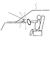
- FIG. 2 shows an example of the terminal device 1 in a state where it is installed in the passenger compartment of the vehicle 3.
- the terminal device 1 is installed at a position on the dashboard where the driver of the vehicle can visually recognize the display unit 15 while being held by the terminal holding device 2.
- the terminal holding device 2 is fixed to an installation surface 3a such as a dashboard of the vehicle 3, and the terminal device 1 is held by the terminal holding device 2 in such a fixed state.
- the terminal device 1 captures the traveling direction of the vehicle 3 (in front of the vehicle 3) with the camera 19.
- basic display control (hereinafter referred to as “basic display control”) performed by the control unit 11 will be described.
- the control unit 11 performs control to display information on a plurality of intermediate points located between the current point and the guide point on a screen corresponding to a real image captured by the camera 19.
- the control unit 11 is located between a current point and a guide point such as an intersection, and the distance to the guide point is a predetermined distance (a plurality of predetermined distances).
- Control to display information about Specifically, the control unit 11 displays information indicating the position of each intermediate point and information indicating the distance from each intermediate point to the guide point (the predetermined distance described above).
- these pieces of information are collectively referred to as “distance information”.
- the control unit 11 displays a line segment indicating the position of each intermediate point on the screen as the distance information (hereinafter, the line segment to be displayed is referred to as a “distance line”), and guide points from each intermediate point Characters indicating the distance value up to are displayed on the screen (hereinafter, the displayed distance value is referred to as “distance value”).
- FIG. 3 is a diagram showing a specific example of the basic display control described above.
- the control unit 11 displays, on the screen 100 corresponding to the real image captured by the camera 19, the intermediate points whose remaining distances to the guide point are 100 [m] and 50 [m].
- Distance information 101 and 102 are respectively displayed. Specifically, for the intermediate point whose distance to the guide point is 100 [m], the control unit 11 indicates the distance line 101a indicating the position of the intermediate point and the distance indicating the distance to the guide point at the intermediate point.
- the value 101b is displayed, and for an intermediate point whose distance to the guide point is 50 [m], a distance line 102a indicating the position of the intermediate point and a distance value 102b indicating the distance to the guide point at the intermediate point Is displayed.
- the control unit 11 When displaying the distance information 101 and 102 as described above, the control unit 11 performs the following processing. First, the control part 11 calculates
- control part 11 converts the latitude longitude calculated
- the control unit 11 defines an intermediate point by a center point in the width direction of the road, obtains a latitude / longitude corresponding to such a center point, and converts the latitude / longitude into screen coordinates. Then, the control part 11 displays a distance line and a distance value on a screen on the basis of the obtained screen coordinate.
- points 101c and 102c represented by broken lines indicate the screen coordinates of the intermediate point where the distance to the guide point is 100 [m] and 50 [m], respectively. Note that the points 101c and 102c represented by broken lines are not actually displayed (the same applies hereinafter).
- the control unit 11 hides the distance information as described above when a predetermined condition is satisfied.
- the control unit 11 performs control to hide the distance information of the intermediate points in accordance with the positional relationship of the plurality of intermediate points on the screen.
- the control unit 11 may appear that the positional relationship (context relationship) on the screen of a plurality of intermediate points is different from the positional relationship (context relationship) on the route of the plurality of intermediate points. In this case, the distance information about the intermediate point located rearward on the route is not displayed.
- the control unit 11 when the distance information of the intermediate point located rearward on the route is displayed in front of the distance information of the intermediate point located forward on the route, the control unit 11 is displayed on the screen. (In other words, when the distance information of the intermediate point located forward on the route is displayed at a position indicating far away on the screen than the distance information of the intermediate point located forward on the route), The distance information of the intermediate point located rearward on the route is not displayed.
- FIG. 4 is a diagram illustrating a specific example of the display control method according to the present embodiment.
- a case where the road shape is a shape turning about 180 degrees is taken as an example.
- FIG. 4A shows a case where the basic display control described above is applied to such a road shape.
- distance information 111 and 112 for the intermediate points whose distances to the guide point are 100 [m] and 50 [m] are displayed, respectively.
- the control unit 11 obtains screen coordinates 111c and 112c of intermediate points whose distances to the guidance point are 100 [m] and 50 [m], and the guidance point is based on the screen coordinates 111c and 112c.
- the distance information 112 of the intermediate point where the distance to the guide point is 50 [m] (that is, the intermediate point located rearward on the route) is the distance to the guide point is 100 [m].
- the distance information 111 of a certain intermediate point (that is, the intermediate point located forward on the route)
- the distance information 111 of the intermediate point whose distance to the guide point is 100 [m] is a position indicating farther on the screen than the distance information 112 of the intermediate point whose distance to the guide point is 50 [m]. It can be seen that is displayed.
- an intermediate point whose distance to the guide point is 50 [m] is more than an intermediate point whose distance to the guide point is 100 [m].
- There is a possibility of causing a recognition error such as passing first.
- the control unit 11 has a distance of 50 [m to a guide point, which is an intermediate point located rearward on the route. ] Is not displayed. That is, the control unit 11 displays only the distance information 111 of the intermediate point that is the intermediate point that is located forward on the route and whose distance to the guide point is 100 [m]. In addition, when the vehicle passes the intermediate point whose distance to the guide point is 100 [m], the control unit 11 is hidden until the intermediate point whose distance to the guide point is 50 [m]. The distance information 112 is displayed. This is because the above-described problem is solved when the vehicle passes an intermediate point whose distance to the guide point is 100 [m].
- control unit 11 actually performs to realize the display control method according to the present embodiment.
- the screen coordinates (X coordinate and Y coordinate) are defined using the X axis and Y axis with the upper left corner of the screen as the reference point.
- the value of the X coordinate (hereinafter referred to as “screen X coordinate” as appropriate) increases as it proceeds to the right of the screen, and the Y coordinate (hereinafter referred to as “screen Y coordinate” as appropriate) is displayed on the screen.
- the value increases as you move downward.
- the position where the screen Y coordinate is large that is, the position in the downward direction of the screen) tends to indicate a position close to the current position.
- the control unit 11 obtains the screen coordinates (screen X coordinate and screen Y coordinate) of each intermediate point according to the coordinate system defined as shown in FIG. Specifically, the control unit 11 first obtains the latitude and longitude of each intermediate point, and converts them into screen coordinates by performing a predetermined calculation on the latitude and longitude.
- FIG. 5B is located between the current point and the guide point, and the distance to the guide point is 50 [m], 100 [m], 150 [m], 200 [m], 250 [m], The case where the intermediate point which is 300 [m] is used is illustrated.
- the control unit 11 includes the intermediate points whose distances to the guide point are 50 [m], 100 [m], 150 [m], 200 [m], 250 [m], and 300 [m], respectively. Are obtained, and screen X coordinates aX to fX and screen Y coordinates aY to fY are obtained from the latitudes and longitudes A to F.
- the road shape is a general shape
- the road shape is a straight line shape (see FIG. 3) or a gentle curve shape
- an intermediate point located far ahead on the route disant to the guide point
- the position on the screen of the (intermediate point) tends to be located lower than the position on the screen of the intermediate point (intermediate point close to the guide point) located rearward on the route.
- a basic tendency is applied such that the position in the lower direction of the screen (that is, the position where the screen Y coordinate is large) indicates a position close to the current position. Because.
- the position on the screen of the intermediate point that is forward on the route is rearward on the route.
- the position on the screen of the intermediate point located rearward on the route may be located below the position on the screen of the intermediate point located forward on the route.
- the position on the screen of the intermediate point whose distance to the guide point is 50 [m] is larger than the position on the screen of the intermediate point whose distance to the guide point is 100 [m].
- the screen Y coordinate “aY” of the intermediate point whose distance to the guide point is 50 [m] is larger than the screen Y coordinate “bY” of the intermediate point whose distance to the guide point is 100 [m].
- AY> bY the order of the plurality of intermediate points sorted by the size of the screen Y coordinate is different from the order of the plurality of intermediate points sorted by the size of the distance to the guide point.
- the control unit 11 compares the order of the plurality of intermediate points sorted by the size of the distance to the guide point with the order of the plurality of intermediate points sorted by the size of the screen Y coordinate. Control to hide the distance information of the intermediate point is performed. Specifically, the control unit 11 sorts the order of a plurality of intermediate points sorted by the magnitude of the distance to the guide point (eg sorted in ascending order) and the size of the screen Y coordinate (eg sorted in ascending order). When the order of the plurality of waypoints is different, the distance information of the waypoints located rearward on the route is not displayed. For example, the control unit 11 determines the intermediate point that is closer to the guide point when the magnitude relationship of the screen Y coordinates is opposite to the magnitude relationship of the distance to the guide point for two intermediate points in the plurality of intermediate points. The distance information is not displayed.
- control unit 11 can hide the distance information other than the above case. That is, in the above, the example in which the distance information is not displayed according to the positional relationship on the screen at a plurality of intermediate points is shown, but the present invention is not limited to this example.
- control unit 11 can hide the distance information when the distance information protrudes from the screen. Specifically, when the screen coordinates corresponding to the latitude and longitude of the intermediate point are outside the range of the currently displayed screen, the control unit 11 hides the distance information of the intermediate point.
- FIG. 6A shows a case where the basic display control described above is applied to such a road shape.
- distance information 121 and 122 for the intermediate points whose distances to the guide point are 100 [m] and 50 [m] are displayed, respectively.
- the screen coordinates 121c of the intermediate point whose distance to the guide point is 100 [m] are located within the screen range, but the intermediate point where the distance to the guide point is 50 [m]. It can be seen that the screen coordinate 122c of the point is located outside the screen range.
- the “screen range” corresponds to an image drawing range.
- the control unit 11 hides the distance information of the intermediate point when the screen coordinates of the intermediate point are located outside the screen range. Specifically, as shown in FIG. 6B, the control unit 11 hides the distance information 122 of the intermediate point where the screen coordinates 122c are not included in the screen. That is, the control unit 11 hides the distance information 122 for the intermediate point whose distance to the guide point is 50 [m], and the distance information 121 for the intermediate point whose distance to the guide point is 100 [m]. Display only. When the distance information about the intermediate point where the screen coordinates are located outside the screen range is not displayed, the control unit 11 displays the screen coordinates from outside the screen range as the vehicle travels toward the guidance point. When it comes to be located within the range, the distance information of the intermediate point is displayed.
- FIG. 7 is a flowchart illustrating the display control process according to the present embodiment. This process is realized by the control unit 11 executing a program stored in advance. The process is repeatedly executed at a predetermined cycle during route guidance.
- step S101 the control unit 11 specifies a plurality of intermediate points that are separated from the guidance point by a plurality of predetermined distances (50 [m], 100 [m], 150 [m], etc.). Find the latitude and longitude of each intermediate point. Specifically, the control unit 11 uses the latitude / longitude of the current point calculated by the GPS unit 14 and the road data (intersection data, etc.) on the currently traveling road acquired from the server via the communication unit 13. Based on this, a plurality of waypoints are specified, and the latitude and longitude of each of the plurality of waypoints are obtained. Then, the process proceeds to step S102.
- a plurality of waypoints are specified, and the latitude and longitude of each of the plurality of waypoints are obtained.
- step S102 the control unit 11 converts the latitude and longitude of the plurality of intermediate points obtained in step S101 into screen coordinates by performing a predetermined calculation. Specifically, the control unit 11 obtains the screen X coordinate and the screen Y coordinate of each of a plurality of latitudes and longitudes. Then, the process proceeds to step S103.
- step S103 the control unit 11 determines whether or not the screen coordinates obtained in step S103 are located outside the range of the currently displayed screen. That is, the control unit 11 determines whether or not the screen coordinates are included in the image drawing range. In this case, the control unit 11 performs the determination using the screen X coordinate and the screen Y coordinate that define a predetermined drawing range.
- step S103 When the screen coordinates are located outside the screen range (step S103; Yes), the control unit 11 excludes the distance information about the intermediate point corresponding to the screen coordinates located outside the screen range from the display target (step S103). S104). In this case, when there are a plurality of screen coordinates located outside the range of the screen, the control unit 11 excludes the distance information of the plurality of intermediate points corresponding to the screen coordinates from the display target. Then, the process proceeds to step S105. On the other hand, when the screen coordinates are not located outside the screen range (step S103; No), that is, when the screen coordinates are located within the screen range, the control unit 11 does not exclude the distance information from the display target. The process proceeds to step S105.
- step S105 the control unit 11 sorts the order of a plurality of intermediate points sorted by the size of the distance to the guide point (for example, sorted in ascending order) and the plurality sorted by the size of the screen Y coordinate (eg sorted by the ascending order). It is determined whether the order of the intermediate points is different. Specifically, the control unit 11 determines whether or not the magnitude relationship between the distances to the guide points and the magnitude relationship between the screen Y coordinates are reversed. In addition, when the process which excludes distance information from display object is performed at step S104, the control part 11 of step S105 with respect to the intermediate point except the intermediate point corresponding to the distance information excluded from display object. Make a decision.
- step S106 the control unit 11 excludes the distance information of the intermediate point located rearward on the route from the display target (step S106). For example, when there are two waypoints in which the magnitude relation of the distance to the guide point and the magnitude relation of the screen Y coordinate are reversed with respect to two waypoints among the plurality of waypoints, the control unit 11 In addition, the distance information of the intermediate point closer to the guide point in the two intermediate points is excluded from the display target. Then, the process proceeds to step S107. On the other hand, when the order sorted by the distance to the guide point matches the order sorted by the screen Y coordinate (step S105; No), the control unit 11 does not exclude the distance information from the display target. The process proceeds to step S107.
- step S107 the control unit 11 performs control for causing the display unit 15 to display only distance information about the waypoint to be displayed. Then, the process ends.
- the distance information of the intermediate points that should not be displayed for the plurality of intermediate points located between the current point and the guide point is appropriately hidden. It can be.
- data calculated from map data is used in the present embodiment, it can be said that the configuration according to the present embodiment is easier to implement than the configuration using a road of a photographed image taken by the camera 19.
- the display mode of the distance information can be changed variously.
- the length of the distance line in the distance information can be changed according to the position on the screen where the distance information is displayed (specifically, according to the screen Y coordinate). For example, a distance line located far away on the screen can be displayed shorter than distance information located on the near side on the screen.
- the length of the distance line can be displayed to match the road width.
- the length of the distance line can be displayed to match the road width based on the road width information included in the road data.
- the distance line and the color of the distance value can be changed and displayed.
- the distance line and distance value located on the front side of the screen may be displayed in a dark color or a conspicuous color, or the distance line and distance value located far away on the screen may be displayed in a light color or translucent. it can.
- the control opposite to the above-described embodiment can be performed.
- the position on the screen of the intermediate point that passes first is located below the position on the screen of the intermediate point that passes later, the distance information of the intermediate point that passes later Can be hidden.
- distance information is used as information regarding a plurality of waypoints.
- information indicating the position of the signal, information indicating the color of the signal at each intermediate point, or the like can be used instead of or in addition to the distance information as information regarding the plurality of intermediate points. .
- Modification 4 In the above description, the embodiment in which the present invention is applied to a real image captured by the camera 19 has been described. In the fourth modification, the present invention is applied to an image expressed three-dimensionally (that is, an image expressed in depth) instead of a photographed image. Specifically, in Modification 4, route guidance can be performed using a three-dimensionally represented map guidance image generated based on map information.
- Modification 5 In the above, the Example which applies this invention to the terminal device 1 was shown.
- the present invention is applied to a transmissive display such as a head-up display or a head-mounted display. That is, in the fifth modification, the image controlled by the control unit 11 as described above can be displayed on a head-up display, a head-mounted display, or the like.
- Modification 6 Although the example which applies this invention to a vehicle was shown above, application of this invention is not limited to this.
- the present invention can be applied to various mobile objects such as ships, helicopters, and airplanes in addition to vehicles.
- the present invention can also be applied to terminal devices used by pedestrians. That is, the “moving body” includes pedestrians.
- the present invention can be used for navigation devices including PNDs, portable terminal devices such as mobile phones, and transmissive displays such as head-up displays and head-mounted displays.
Landscapes
- Engineering & Computer Science (AREA)
- Radar, Positioning & Navigation (AREA)
- Remote Sensing (AREA)
- Automation & Control Theory (AREA)
- Multimedia (AREA)
- Physics & Mathematics (AREA)
- General Physics & Mathematics (AREA)
- Navigation (AREA)
- Instructional Devices (AREA)
Abstract
ナビゲーション装置は、現在地点からの景色を示す画像を用いて経路案内を行い、現在地点と経路上の案内地点との間に位置する複数の中間地点に関する情報を、それぞれ、画像上において複数の中間地点に対応する位置に表示する制御を行う表示制御手段を備える。表示制御手段は、複数の中間地点の画像上での位置関係と、複数の中間地点の経路上での位置関係とに基づいて、複数の中間地点の少なくとも1つについて中間地点に関する情報を非表示とする制御を行う。これにより、現在地点と案内地点との間に位置する複数の中間地点について、表示させるべきでない中間地点に関する情報を、適切に非表示とすることができる。
Description
本発明は、ナビゲーション装置の技術分野に関する。
従来より、車両に設置したカメラで前方の風景を撮影し、撮影した実写の風景画像を用いて、案内表示を行うナビゲーション装置が知られている。また、このようなナビゲーション装置において、実写の風景画像上の案内対象交差点に相当する箇所に進路情報を重畳表示すると共に、当該案内対象交差点までの距離情報をユーザに提示する技術が提案されている(例えば特許文献1参照)。
しかしながら、従来の技術では、道路形状などによっては、画面に表示されている複数の距離情報の位置関係が、当該複数の距離情報に対応する実際の地点の位置関係と異なって見えてしまうといった不具合が発生する場合があった。例えば、経路上で後方に位置する地点の距離情報が、経路上で前方に位置する地点の距離情報よりも、画面上で手前に表示されてしまう場合に、このような不具合が発生し得る。
本発明が解決しようとする課題は上記のようなものが例として挙げられる。本発明は、案内地点までの中間地点に関する情報を、中間地点の画面上の位置に応じて適切に表示制御することが可能なナビゲーション装置、ナビゲーション方法及びナビゲーションプログラム、並びに透過型ディスプレイを提供することを課題とする。
請求項1に記載の発明では、現在地点からの景色を示す画像を用いて経路案内を行うナビゲーション装置は、前記現在地点と経路上の案内地点との間に位置する複数の中間地点に関する情報を、それぞれ、前記画像上において前記複数の中間地点に対応する位置に表示する制御を行う表示制御手段を備え、前記表示制御手段は、前記複数の中間地点の前記画像上での位置関係と、前記複数の中間地点の前記経路上での位置関係とに基づいて、前記複数の中間地点の少なくとも1つについて前記中間地点に関する情報を非表示とする制御を行う。
請求項8に記載の発明では、透過型ディスプレイは、請求項1乃至7のいずれか一項に記載の表示制御手段によって制御された画像を表示する。
請求項9に記載の発明では、現在地点からの景色を示す画像を用いて経路案内を行うナビゲーション装置によって実行されるナビゲーション方法は、前記現在地点と経路上の案内地点との間に位置する複数の中間地点に関する情報を、それぞれ、前記画像上において前記複数の中間地点に対応する位置に表示する制御を行う表示制御工程を備え、前記表示制御工程は、前記複数の中間地点の前記画像上での位置関係と、前記複数の中間地点の前記経路上での位置関係とに基づいて、前記複数の中間地点の少なくとも1つについて前記中間地点に関する情報を非表示とする制御を行う。
請求項10に記載の発明では、コンピュータを備え、現在地点からの景色を示す画像を用いて経路案内を行うナビゲーション装置によって実行されるナビゲーションプログラムは、前記現在地点と経路上の案内地点との間に位置する複数の中間地点に関する情報を、それぞれ、前記画像上において前記複数の中間地点に対応する位置に表示する制御を行う表示制御手段、として前記コンピュータを機能させ、前記表示制御手段は、前記複数の中間地点の前記画像上での位置関係と、前記複数の中間地点の前記経路上での位置関係とに基づいて、前記複数の中間地点の少なくとも1つについて前記中間地点に関する情報を非表示とする制御を行う。
本発明の1つの観点では、現在地点からの景色を示す画像を用いて経路案内を行うナビゲーション装置は、前記現在地点と経路上の案内地点との間に位置する複数の中間地点に関する情報を、それぞれ、前記画像上において前記複数の中間地点に対応する位置に表示する制御を行う表示制御手段を備え、前記表示制御手段は、前記複数の中間地点の前記画像上での位置関係と、前記複数の中間地点の前記経路上での位置関係とに基づいて、前記複数の中間地点の少なくとも1つについて前記中間地点に関する情報を非表示とする制御を行う。
上記のナビゲーション装置は、移動体などに搭載された状態で利用され、現在地点からの景色を示す画像を用いて経路案内を行う。表示制御手段は、現在地点と経路上の案内地点との間に位置する複数の中間地点に関する情報を、それぞれ、画像上において複数の中間地点に対応する位置に表示する制御を行う。この場合において、表示制御手段は、複数の中間地点の画像上での位置関係と、複数の中間地点の経路上での位置関係とに基づいて、複数の中間地点の少なくとも1つについて中間地点に関する情報を非表示とする制御を行う。具体的には、表示制御手段は、複数の中間地点の画像上での位置関係が、複数の中間地点の実際の経路上での位置関係と異なるように見えてしまう場合に、経路上で後方に位置する中間地点に関する情報を非表示とする。これにより、現在地点と案内地点との間に位置する複数の中間地点について、表示させるべきでない中間地点に関する情報を、適切に非表示とすることができる。
上記のナビゲーション装置の一態様では、前記表示制御手段は、前記複数の中間地点の1つの中間地点が他の中間地点よりも前記経路上の後方に位置し、且つ、当該他の中間地点の前記画像上での位置が当該1つの中間地点の前記画像上での位置よりも前記画像上で遠方を示す位置である場合に、当該1つの中間地点に関する情報を非表示とする。
この態様では、表示制御手段は、経路上で後方に位置する中間地点に関する情報が、経路上で前方に位置する中間地点に関する情報よりも画像上において手前に表示されてしまうような場合に、経路上で後方に位置する中間地点に関する情報を非表示とする。これにより、ユーザの認識ミスを適切に抑制することが可能となる。
上記のナビゲーション装置において好適には、前記表示制御手段は、前記他の中間地点の前記画像上での位置が前記1つの中間地点の前記画像上での位置よりも上側に位置する場合に、当該1つの中間地点に関する情報を非表示とすることができる。
上記のナビゲーション装置の他の一態様では、前記表示制御手段は、前記1つの中間地点に関する情報を非表示とした場合において、前記現在地点が前記他の中間地点に到達した際に、当該1つの中間地点に関する情報を表示する。これにより、それまで非表示としていた中間地点に関する情報を、適切に表示させることができる。
上記のナビゲーション装置の他の一態様では、前記表示制御手段は、前記現在地点及び地図データに基づいて、前記複数の中間地点を特定すると共に、当該複数の中間地点のそれぞれについての緯度経度を求める手段と、前記複数の中間地点のそれぞれについての前記緯度経度を、前記画像上での座標に変換する手段と、を備え、前記複数の中間地点のそれぞれについての前記座標に基づいて、前記複数の中間地点の前記画像上での位置関係を判断する。この態様では、複数の中間地点における画像上での座標の大小関係に応じて、中間地点に関する情報を非表示とする制御を行うことができる。
好適な例では、前記複数の中間地点に関する情報は、当該複数の中間地点の位置を示す情報、及び当該複数の中間地点の各々から前記案内地点までの距離を示す情報を含む。
また好適な例では、前記画像は、移動体の進行方向を撮影した画像である。
上記したように表示制御手段によって制御された画像は、ヘッドアップディスプレイやヘッドマウントディスプレイなどの透過型ディスプレイによって好適に表示させることができる。
本発明の他の観点では、現在地点からの景色を示す画像を用いて経路案内を行うナビゲーション装置によって実行されるナビゲーション方法は、前記現在地点と経路上の案内地点との間に位置する複数の中間地点に関する情報を、それぞれ、前記画像上において前記複数の中間地点に対応する位置に表示する制御を行う表示制御工程を備え、前記表示制御工程は、前記複数の中間地点の前記画像上での位置関係と、前記複数の中間地点の前記経路上での位置関係とに基づいて、前記複数の中間地点の少なくとも1つについて前記中間地点に関する情報を非表示とする制御を行う。
本発明の更に他の観点では、コンピュータを備え、現在地点からの景色を示す画像を用いて経路案内を行うナビゲーション装置によって実行されるナビゲーションプログラムは、前記現在地点と経路上の案内地点との間に位置する複数の中間地点に関する情報を、それぞれ、前記画像上において前記複数の中間地点に対応する位置に表示する制御を行う表示制御手段、として前記コンピュータを機能させ、前記表示制御手段は、前記複数の中間地点の前記画像上での位置関係と、前記複数の中間地点の前記経路上での位置関係とに基づいて、前記複数の中間地点の少なくとも1つについて前記中間地点に関する情報を非表示とする制御を行う。
上記のナビゲーション方法及びナビゲーションプログラムによっても、現在地点と案内地点との間に位置する複数の中間地点について、表示させるべきでない中間地点に関する情報を、適切に非表示とすることができる。
なお、上記ナビゲーションプログラムは、記録媒体に記録した状態で好適に取り扱うことができる。
以下、図面を参照して本発明の好適な実施例について説明する。
[装置構成]
図1は、本実施例に係る端末装置のブロック図を概略的に示している。端末装置1は、主に、制御部11と、記憶部12と、通信部13と、GPSユニット14と、表示部15と、スピーカ16と、マイク17と、操作部18と、カメラ19とを有する。端末装置1は、スマートフォンなどの通話機能を有する携帯型端末装置である。例えば、端末装置1は、端末保持装置などに保持された状態で、車両の運転者が表示部15を視認できるようなダッシュボード上の位置に設置される。なお、端末装置1は、本発明に係るナビゲーション装置の一例である。
図1は、本実施例に係る端末装置のブロック図を概略的に示している。端末装置1は、主に、制御部11と、記憶部12と、通信部13と、GPSユニット14と、表示部15と、スピーカ16と、マイク17と、操作部18と、カメラ19とを有する。端末装置1は、スマートフォンなどの通話機能を有する携帯型端末装置である。例えば、端末装置1は、端末保持装置などに保持された状態で、車両の運転者が表示部15を視認できるようなダッシュボード上の位置に設置される。なお、端末装置1は、本発明に係るナビゲーション装置の一例である。
通信部13は、通信網を介して他の端末装置1と無線通信を行うことが可能に構成されている。また、通信部13は、例えばVICSセンタなどのサーバと無線通信を行うことが可能に構成されている。通信部13は、このようなサーバから、例えば地図情報や渋滞情報などのデータを受信することができる。GPSユニット14は、複数のGPS衛星から測位用データを含む電波を受信し、測位用データに基づいて端末装置1の現在位置を算出する。
表示部15は、例えば液晶ディスプレイなどにより構成され、ユーザに対して文字、画像などを表示する。スピーカ16は、ユーザに対して音声出力を行い、マイク17は、ユーザによって発せられた音声などを集音する。
操作部18は、端末装置1の筐体に設けられた操作ボタンやタッチパネル式入力装置などにより構成することができ、ユーザによる各種の選択、指示が入力される。なお、表示部15がタッチパネル方式である場合には、表示部15の表示画面上に設けられたタッチパネルも操作部18として機能する。カメラ19は、例えばCCDカメラにより構成され、撮影画像を生成する。
記憶部12は、ROMやRAMなどを備えて構成され、端末装置1を制御するための制御プログラム等が格納されると共に、操作部18を介してユーザにより設定されたデータを読み出し可能に格納したり、制御部11に対してワーキングエリアを提供したりする。なお、記憶部12に、地図情報や施設データなどの経路案内処理に用いられる各種データを記憶させておくこととしても良い。
制御部11は、CPU(Central Processing Unit)などを有しており、端末装置1の全体の制御を行う。例えば、制御部11は、通信部13を介してサーバより地図情報などを取得して、目的地までの経路案内を行うための処理を実行する。この場合、制御部11は、主に、カメラ19によって撮影された実写画像を用いたナビゲーションを行う。当該ナビゲーションは、ARナビ(AR:Augmented Reality)などと呼ばれ、実写画像上に、案内地や目的地までの方向や距離などの経路案内のための画像を重ねて表示するものである。制御部11は、本発明における表示制御手段として機能し、上記のような経路案内を行うための案内画面を表示部15に表示させる制御を行う。
図2は、車両3の車室内に設置された状態にある端末装置1の一例を示している。図2に示すように、端末装置1は、端末保持装置2に保持された状態で、車両の運転者が表示部15を視認できるようなダッシュボード上の位置に設置される。具体的には、端末保持装置2は車両3のダッシュボードなどの設置面3aに固定され、このように固定された状態にある端末保持装置2によって端末装置1が保持される。また、図2中の破線で示すように、端末装置1は、カメラ19によって、車両3の進行方向(車両3の前方)を撮影する。
[表示制御方法]
次に、本実施例に係る表示制御方法について説明する。
次に、本実施例に係る表示制御方法について説明する。
まず、制御部11が行う基本的な表示制御(以下、「基本表示制御」と呼ぶ。)について説明する。制御部11は、基本表示制御として、カメラ19によって撮影された実写画像に対応する画面上に、現在地点と案内地点との間に位置する複数の中間地点に関する情報を表示させる制御を行う。具体的には、制御部11は、現在地点と交差点などの案内地点との間に位置し、且つ、案内地点までの距離が所定距離(予め定めた複数の距離)である、複数の中間地点に関する情報を表示させる制御を行う。詳しくは、制御部11は、各中間地点の位置を示す情報と、各中間地点から案内地点までの距離(上記した所定距離)を示す情報とを表示させる。以下、これらの情報をまとめて「距離情報」と呼ぶ。この場合、制御部11は、距離情報として、各中間地点の位置を示す線分を画面上に表示させると共に(以下、表示する線分を「距離線」と呼ぶ)、各中間地点から案内地点までの距離の値を示す文字を画面上に表示させる(以下、表示する距離の値を「距離値」と呼ぶ)。
図3は、上記した基本表示制御についての具体例を示す図である。図3に示すように、制御部11は、カメラ19によって撮影された実写画像に対応する画面100上に、案内地点までの残りの距離が100[m]、50[m]である中間地点についての距離情報101、102をそれぞれ表示させる。具体的には、制御部11は、案内地点までの距離が100[m]である中間地点について、当該中間地点の位置を示す距離線101aと、当該中間地点における案内地点までの距離を示す距離値101bとを表示させると共に、案内地点までの距離が50[m]である中間地点について、当該中間地点の位置を示す距離線102aと、当該中間地点における案内地点までの距離を示す距離値102bとを表示させる。
上記のような距離情報101、102を表示させる際に、制御部11は以下のような処理を行う。まず、制御部11は、案内地点までの距離が100[m]及び50[m]である中間地点のそれぞれの緯度経度を、現在地点及び地図データに基づいて求める。具体的には、制御部11は、GPSユニット14によって算出された現在地点の緯度経度と、通信部13を介してサーバより取得された現在走行中の道路のデータ(交差点のデータなど)とに基づいて、案内地点までの距離が100[m]及び50[m]である中間地点のそれぞれの緯度経度を求める。そして、制御部11は、こうして求められた緯度経度を、所定の演算を行うことで、画面内の座標(以下、「画面座標」と呼ぶ。)に変換する。1つの例では、制御部11は、道路の幅方向における中心点によって中間地点を規定し、このような中心点に対応する緯度経度を求めて、当該緯度経度を画面座標に変換する。この後、制御部11は、得られた画面座標を基準にして、距離線及び距離値を画面に表示させる。
図3においては、破線で表された点101c、102cが、それぞれ、案内地点までの距離が100[m]及び50[m]である中間地点の画面座標を示している。なお、破線で表された点101c、102cは、実際には表示されない(以下同様とする)。
次に、本実施例において制御部11が行う表示制御方法について説明する。本実施例では、制御部11は、上記したような距離情報を、所定の条件が成立する場合に非表示とする。本実施例では、制御部11は、複数の中間地点の画面上での位置関係に応じて、中間地点の距離情報を非表示とする制御を行う。具体的には、制御部11は、複数の中間地点の画面上での位置関係(前後関係)が、複数の中間地点の経路上での位置関係(前後関係)と異なって見えてしまうような場合に、経路上で後方に位置する中間地点についての距離情報を非表示とする。詳しくは、制御部11は、経路上で後方に位置する中間地点の距離情報が、経路上で前方に位置する中間地点の距離情報よりも、画面上で手前に表示されてしまうような場合に(言い換えると、経路上で前方に位置する中間地点の距離情報が、経路上で前方に位置する中間地点の距離情報よりも、画面上で遠方を示す位置に表示されてしまうような場合)、経路上で後方に位置する中間地点の距離情報を非表示とする。
図4は、本実施例に係る表示制御方法の具体例を示す図である。ここでは、道路形状が略180度ターンしている形状である場合を例に挙げる。図4(a)は、このような道路形状に対して、上記した基本表示制御を適用した場合を示している。この場合には、案内地点までの距離が100[m]、50[m]である中間地点についての距離情報111、112がそれぞれ表示される。具体的には、制御部11は、案内地点までの距離が100[m]及び50[m]である中間地点の画面座標111c、112cを求め、画面座標111c、112cを基準にして、案内地点までの距離が100[m]である中間地点の距離線111a及び距離値111bを距離情報111として表示させると共に、案内地点までの距離が50[m]である中間地点の距離線112a及び距離値112bを距離情報112として表示させる。
図4(a)より、案内地点までの距離が50[m]である中間地点(つまり経路上で後方に位置する中間地点)の距離情報112が、案内地点までの距離が100[m]である中間地点(つまり経路上で前方に位置する中間地点)の距離情報111よりも、画面上で手前に表示されていることがわかる、言い換えると画面上において現在地点に近い位置に表示されていることがわかる。つまり、案内地点までの距離が100[m]である中間地点の距離情報111が、案内地点までの距離が50[m]である中間地点の距離情報112よりも、画面上で遠方を示す位置に表示されていることがわかる。図4(a)に示すような画面が表示された場合には、例えば案内地点までの距離が100[m]である中間地点よりも案内地点までの距離が50[m]である中間地点を先に通過する、といった認識ミスを生じさせてしまう可能性がある。
本実施例では、このような不具合を防止すべく、制御部11は、図4(b)に示すように、経路上で後方に位置する中間地点である、案内地点までの距離が50[m]である中間地点の距離情報112を非表示とする。つまり、制御部11は、経路上で前方に位置する中間地点である、案内地点までの距離が100[m]である中間地点の距離情報111のみを表示させる。なお、制御部11は、案内地点までの距離が100[m]である中間地点を車両が通過した際に、それまで非表示としていた、案内地点までの距離が50[m]である中間地点の距離情報112を表示させる。こうするのは、案内地点までの距離が100[m]である中間地点を車両が通過した時点で、上記した不具合が解消することとなるからである。
次に、図5を参照して、本実施例に係る表示制御方法を実現するために制御部11が実際に行う処理について説明する。
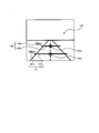
図5(a)に示すように、画面の左上を基準点としたX軸及びY軸を用いて、画面座標(X座標及びY座標)を規定する。この場合、X座標(以下、適宜「画面X座標」と呼ぶ。)は画面の右方向に進むほど値が大きくなり、Y座標(以下、適宜「画面Y座標」と表記する。)は画面の下方向に進むほど値が大きくなる。基本的には、実写画像に対応する画面においては、画面Y座標が大となる位置(つまり画面の下方向の位置)が現在地点に近い位置を示す傾向にある。
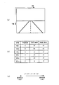
制御部11は、図5(a)に示すように規定された座標系に従って、各中間地点の画面座標(画面X座標及び画面Y座標)を求める。具体的には、制御部11は、まず各中間地点の緯度経度を求めて、当該緯度経度に対して所定の演算を行うことで画面座標に変換する。図5(b)は、現在地点と案内地点との間に位置し、案内地点までの距離が50[m]、100[m]、150[m]、200[m]、250[m]、300[m]である中間地点を用いた場合を例示している。この例では、制御部11は、案内地点までの距離が50[m]、100[m]、150[m]、200[m]、250[m]、300[m]である中間地点のそれぞれの緯度経度A~Fを求めて、緯度経度A~Fから画面X座標aX~fX及び画面Y座標aY~fYを求める。
ここで、道路形状が一般的な形状である場合、例えば道路形状が直線形状(図3参照)や緩やかなカーブ形状である場合には、経路上で前方に位置する中間地点(案内地点まで遠い中間地点)の画面上の位置が、経路上で後方に位置する中間地点(案内地点まで近い中間地点)の画面上の位置よりも、下側に位置する傾向にある。これは、道路形状が一般的な形状である場合には、画面の下方向の位置(つまり画面Y座標が大となる位置)が現在地点に近い位置を示すといった基本的な傾向が適用されるからである。図5(b)に示した例に適用すると、各中間地点の画面Y座標について「aY<bY<cY<dY<eY<fY」といった関係が成立することとなる(図5(c)参照)。このような画面Y座標の大きさでソートした複数の中間地点の順序は、案内地点までの距離の大きさでソートした複数の中間地点の順序と一致する。この場合には、基本的には、図4(a)に示したような不具合は発生しない。
他方で、道路形状が例えば略180度ターンしている形状である場合には、経路上で前方に位置する中間地点(案内地点まで遠い中間地点)の画面上の位置が、経路上で後方に位置する中間地点(案内地点まで近い中間地点)の画面上の位置よりも、下側に位置しない場合がある。つまり、経路上で後方に位置する中間地点の画面上の位置が、経路上で前方に位置する中間地点の画面上の位置よりも、下側に位置する場合がある。図4に示した例では、案内地点までの距離が50[m]である中間地点の画面上の位置が、案内地点までの距離が100[m]である中間地点の画面上の位置よりも、下側に位置している。即ち、案内地点までの距離が50[m]である中間地点の画面Y座標「aY」が、案内地点までの距離が100[m]である中間地点の画面Y座標「bY」よりも大きくなっている(aY>bY)。この場合には、画面Y座標の大きさでソートした複数の中間地点の順序が、案内地点までの距離の大きさでソートした複数の中間地点の順序と異なることとなる。
以上のことから、制御部11は、案内地点までの距離の大きさでソートした複数の中間地点の順序と、画面Y座標の大きさでソートした複数の中間地点の順序とを比較することで、中間地点の距離情報を非表示とする制御を行う。具体的には、制御部11は、案内地点までの距離の大きさでソート(例えば昇順でソート)した複数の中間地点の順序と、画面Y座標の大きさでソート(例えば昇順でソート)した複数の中間地点の順序とが異なる場合に、経路上で後方に位置する中間地点の距離情報を非表示とする。例えば、制御部11は、複数の中間地点における2つの中間地点について、画面Y座標の大小関係が案内地点までの距離の大小関係と逆になっている場合に、案内地点に近いほうの中間地点の距離情報を非表示とする。
なお、制御部11は、上記したような場合以外にも、距離情報を非表示とすることができる。つまり、上記では複数の中間地点における画面上の位置関係に応じて距離情報を非表示とする例を示したが、この例に限定はされない。他の例では、制御部11は、距離情報が画面からはみ出してしまうような場合に、当該距離情報を非表示とすることができる。具体的には、制御部11は、中間地点の緯度経度に対応する画面座標が、現在表示している画面の範囲外である場合に、当該中間地点の距離情報を非表示とする。
図6を参照して、他の例に係る表示制御方法の具体例について説明する。ここでは、道路形状が急にカーブしている形状である場合を例に挙げる。図6(a)は、このような道路形状に対して、上記した基本表示制御を適用した場合を示している。この場合には、案内地点までの距離が100[m]、50[m]である中間地点についての距離情報121、122がそれぞれ表示される。図6(a)より、案内地点までの距離が100[m]である中間地点の画面座標121cは画面の範囲内に位置しているが、案内地点までの距離が50[m]である中間地点の画面座標122cが画面の範囲外に位置していることがわかる。なお、「画面の範囲」は、画像の描画範囲に相当する。
他の例では、制御部11は、このように中間地点の画面座標が画面の範囲外に位置する場合に、当該中間地点の距離情報を非表示とする。具体的には、図6(b)に示すように、制御部11は、画面座標122cが画面に含まれない中間地点の距離情報122を非表示とする。つまり、制御部11は、案内地点までの距離が50[m]である中間地点についての距離情報122を非表示とし、案内地点までの距離が100[m]である中間地点についての距離情報121のみを表示させる。なお、制御部11は、画面座標が画面の範囲外に位置する中間地点についての距離情報を非表示とした場合において、車両が案内地点に向かって進行するにつれて画面座標が画面の範囲外から画面の範囲内に位置するようになった際に、当該中間地点の距離情報を表示させる。
[表示制御処理]
次に、図7を参照して、本実施例に係る表示制御処理について説明する。図7は、本実施例に係る表示制御処理を示すフローチャートである。当該処理は、制御部11が予め記憶されたプログラムを実行することにより実現される。また、当該処理は、経路案内中において、所定の周期で繰り返し実行される。
次に、図7を参照して、本実施例に係る表示制御処理について説明する。図7は、本実施例に係る表示制御処理を示すフローチャートである。当該処理は、制御部11が予め記憶されたプログラムを実行することにより実現される。また、当該処理は、経路案内中において、所定の周期で繰り返し実行される。
まず、ステップS101では、制御部11は、予め定めた複数の距離(50[m]、100[m]、150[m]など)だけ案内地点から離れた複数の中間地点を特定し、当該複数の中間地点のそれぞれの緯度経度を求める。具体的には、制御部11は、GPSユニット14によって算出された現在地点の緯度経度と、通信部13を介してサーバより取得された現在走行中の道路のデータ(交差点のデータなど)とに基づいて、複数の中間地点を特定すると共に、当該複数の中間地点のそれぞれの緯度経度を求める。そして、処理はステップS102に進む。
ステップS102では、制御部11は、ステップS101で求められた複数の中間地点の緯度経度に対して所定の演算を行うことで画面座標に変換する。具体的には、制御部11は、複数の緯度経度のそれぞれの画面X座標及び画面Y座標を求める。そして、処理はステップS103に進む。
ステップS103では、制御部11は、ステップS103で求められた画面座標が、現在表示している画面の範囲外に位置するか否かを判定する。つまり、制御部11は、画面座標が画像の描画範囲に含まれないか否かを判定する。この場合、制御部11は、予め定められた描画範囲を規定する画面X座標及び画面Y座標を用いて、当該判定を行う。
画面座標が画面の範囲外に位置する場合(ステップS103;Yes)、制御部11は、画面の範囲外に位置する画面座標に対応する中間地点についての距離情報を、表示対象から除外する(ステップS104)。この場合、制御部11は、画面の範囲外に位置する画面座標が複数存在する場合には、それらの画面座標に対応する複数の中間地点の距離情報を表示対象から除外する。そして、処理はステップS105に進む。これに対して、画面座標が画面の範囲外に位置しない場合(ステップS103;No)、つまり画面座標が画面の範囲内に位置する場合、制御部11は距離情報を表示対象から除外することなく、処理はステップS105に進む。
ステップS105では、制御部11は、案内地点までの距離の大きさでソート(例えば昇順でソート)した複数の中間地点の順序と、画面Y座標の大きさでソート(例えば昇順でソート)した複数の中間地点の順序とが異なるか否かを判定する。具体的には、制御部11は、案内地点までの距離の大小関係と画面Y座標の大小関係とが逆になっているか否かを判定する。なお、制御部11は、ステップS104で距離情報を表示対象から除外する処理を行った場合には、表示対象から除外した距離情報に対応する中間地点を除いた中間地点に対して、ステップS105の判定を行う。
案内地点までの距離でソートした順序と画面Y座標でソートした順序とが異なる場合(ステップS105;Yes)、処理はステップS106に進む。この場合、制御部11は、経路上で後方に位置する中間地点の距離情報を表示対象から除外する(ステップS106)。例えば、制御部11は、複数の中間地点の中の2つの中間地点に関して、案内地点までの距離の大小関係と画面Y座標の大小関係とが逆になっている2つの中間地点が存在する場合に、当該2つの中間地点において案内地点に近いほうの中間地点の距離情報を表示対象から除外する。そして、処理はステップS107に進む。これに対して、案内地点までの距離でソートした順序と画面Y座標でソートした順序とが一致している場合(ステップS105;No)、制御部11は距離情報を表示対象から除外することなく、処理はステップS107に進む。
ステップS107では、制御部11は、表示対象となっている中間地点についての距離情報のみを表示部15に表示させる制御を行う。そして、処理は終了する。
以上説明した本実施例に係る表示制御処理によれば、現在地点と案内地点との間に位置する複数の中間地点について、距離情報を表示させるべきでない中間地点の距離情報を、適切に非表示とすることができる。また、本実施例では地図データから計算したデータを用いるため、本実施例に係る構成は、カメラ19によって撮影された実写画像の道路を用いる構成と場合と比して、実現し易いと言える。
[変形例]
以下では、上記した実施例の変形例を提示する。
以下では、上記した実施例の変形例を提示する。
(変形例1)
変形例1では、距離情報の表示態様を種々に変えることができる。1つの例では、距離情報を表示させる画面上の位置に応じて(具体的には画面Y座標に応じて)、距離情報における距離線の長さを変えて表示させることができる。例えば、画面上で遠方に位置する距離線を、画面上で手前に位置する距離情報よりも短く表示させることができる。
変形例1では、距離情報の表示態様を種々に変えることができる。1つの例では、距離情報を表示させる画面上の位置に応じて(具体的には画面Y座標に応じて)、距離情報における距離線の長さを変えて表示させることができる。例えば、画面上で遠方に位置する距離線を、画面上で手前に位置する距離情報よりも短く表示させることができる。
他の例では、距離線の長さを道路幅に合わせるように表示させることができる。この例では、道路データが有する道路幅の情報に基づいて、距離線の長さを道路幅に合わせるように表示させることができる。
更に他の例では、距離情報を表示させる画面上の位置に応じて(具体的には画面Y座標に応じて)、距離線及び距離値の色を変えて表示させることができる。例えば、画面上で手前に位置する距離線及び距離値を濃い色や目立つ色で表示させたり、画面上で遠方に位置する距離線及び距離値を薄い色や半透明で表示させたりすることができる。
(変形例2)
上記した実施例では、先に経由する中間地点の画面上の位置が後に経由する中間地点の画面上の位置よりも上側に位置する場合に、後に経由する中間地点の距離情報を非表示としていた。この実施例では、消失点が画面の中央付近に位置することを前提にしていた(例えば図3など参照)。
上記した実施例では、先に経由する中間地点の画面上の位置が後に経由する中間地点の画面上の位置よりも上側に位置する場合に、後に経由する中間地点の距離情報を非表示としていた。この実施例では、消失点が画面の中央付近に位置することを前提にしていた(例えば図3など参照)。
変形例2では、消失点が画面の下側に位置する場合に、上記した実施例とは逆の制御を行うことができる。具体的には、変形例2では、先に経由する中間地点の画面上の位置が後に経由する中間地点の画面上の位置よりも下側に位置する場合に、後に経由する中間地点の距離情報を非表示とすることができる。
(変形例3)
上記した実施例では、複数の中間地点に関する情報として距離情報を用いていた。変形例3では、複数の中間地点に関する情報として、距離情報の代わりに又は距離情報に加えて、信号の位置を示す情報や、各中間地点での信号の色を示す情報などを用いることができる。
上記した実施例では、複数の中間地点に関する情報として距離情報を用いていた。変形例3では、複数の中間地点に関する情報として、距離情報の代わりに又は距離情報に加えて、信号の位置を示す情報や、各中間地点での信号の色を示す情報などを用いることができる。
(変形例4)
上記では、本発明を、カメラ19によって撮影された実写画像に適用する実施例を示した。変形例4は、実写画像の代わりに、3次元表現された画像(つまり奥行き表現された画像)に本発明を適用するものである。具体的には、変形例4では、地図情報に基づいて生成された、3次元表現された地図案内画像を用いて経路案内を行うことができる。
上記では、本発明を、カメラ19によって撮影された実写画像に適用する実施例を示した。変形例4は、実写画像の代わりに、3次元表現された画像(つまり奥行き表現された画像)に本発明を適用するものである。具体的には、変形例4では、地図情報に基づいて生成された、3次元表現された地図案内画像を用いて経路案内を行うことができる。
(変形例5)
上記では、本発明を端末装置1に適用する実施例を示した。変形例5では、ヘッドアップディスプレイやヘッドマウントディスプレイなどの透過型ディスプレイに本発明を適用するものである。つまり、変形例5では、前述したような制御部11によって制御された画像を、ヘッドアップディスプレイやヘッドマウントディスプレイなどで表示させることができる。
上記では、本発明を端末装置1に適用する実施例を示した。変形例5では、ヘッドアップディスプレイやヘッドマウントディスプレイなどの透過型ディスプレイに本発明を適用するものである。つまり、変形例5では、前述したような制御部11によって制御された画像を、ヘッドアップディスプレイやヘッドマウントディスプレイなどで表示させることができる。
(変形例6)
上記では本発明を車両に適用する例を示したが、本発明の適用はこれに限定されない。本発明は、車両の他に、船や、ヘリコプターや、飛行機などの種々の移動体に適用することができる。加えて、本発明は、歩行者が利用する端末装置にも適用することができる。つまり、「移動体」には歩行者も含まれる。
上記では本発明を車両に適用する例を示したが、本発明の適用はこれに限定されない。本発明は、車両の他に、船や、ヘリコプターや、飛行機などの種々の移動体に適用することができる。加えて、本発明は、歩行者が利用する端末装置にも適用することができる。つまり、「移動体」には歩行者も含まれる。
以上に述べたように、実施例は、上述した実施例に限られるものではなく、特許請求の範囲及び明細書全体から読み取れる発明の要旨あるいは思想に反しない範囲で適宜変更可能である。
本発明は、PNDなどを含むナビゲーション装置や、携帯電話などの携帯型端末装置や、ヘッドアップディスプレイやヘッドマウントディスプレイなどの透過型ディスプレイに利用することができる。
1 端末装置
11 制御部
12 記憶部
13 通信部
14 GPSユニット
15 表示部
19 カメラ
11 制御部
12 記憶部
13 通信部
14 GPSユニット
15 表示部
19 カメラ
Claims (11)
- 現在地点からの景色を示す画像を用いて経路案内を行うナビゲーション装置であって、
前記現在地点と経路上の案内地点との間に位置する複数の中間地点に関する情報を、それぞれ、前記画像上において前記複数の中間地点に対応する位置に表示する制御を行う表示制御手段を備え、
前記表示制御手段は、前記複数の中間地点の前記画像上での位置関係と、前記複数の中間地点の前記経路上での位置関係とに基づいて、前記複数の中間地点の少なくとも1つについて前記中間地点に関する情報を非表示とする制御を行うことを特徴とするナビゲーション装置。 - 前記表示制御手段は、前記複数の中間地点の1つの中間地点が他の中間地点よりも前記経路上の後方に位置し、且つ、当該他の中間地点の前記画像上での位置が当該1つの中間地点の前記画像上での位置よりも前記画像上で遠方を示す位置である場合に、当該1つの中間地点に関する情報を非表示とすることを特徴とする請求項1に記載のナビゲーション装置。
- 前記表示制御手段は、前記他の中間地点の前記画像上での位置が前記1つの中間地点の前記画像上での位置よりも上側に位置する場合に、当該1つの中間地点に関する情報を非表示とすることを特徴とする請求項2に記載のナビゲーション装置。
- 前記表示制御手段は、前記1つの中間地点に関する情報を非表示とした場合において、前記現在地点が前記他の中間地点に到達した際に、当該1つの中間地点に関する情報を表示することを特徴とする請求項2又は3に記載のナビゲーション装置。
- 前記表示制御手段は、
前記現在地点及び地図データに基づいて、前記複数の中間地点を特定すると共に、当該複数の中間地点のそれぞれについての緯度経度を求める手段と、
前記複数の中間地点のそれぞれについての前記緯度経度を、前記画像上での座標に変換する手段と、を備え、
前記複数の中間地点のそれぞれについての前記座標に基づいて、前記複数の中間地点の前記画像上での位置関係を判断することを特徴とする請求項1乃至4のいずれか一項に記載のナビゲーション装置。 - 前記複数の中間地点に関する情報は、当該複数の中間地点の位置を示す情報、及び当該複数の中間地点の各々から前記案内地点までの距離を示す情報を含むことを特徴とする請求項1乃至5のいずれか一項に記載のナビゲーション装置。
- 前記画像は、移動体の進行方向を撮影した画像であることを特徴とする請求項1乃至6のいずれか一項に記載のナビゲーション装置。
- 請求項1乃至7のいずれか一項に記載の表示制御手段によって制御された画像を表示することを特徴とする透過型ディスプレイ。
- 現在地点からの景色を示す画像を用いて経路案内を行うナビゲーション装置によって実行されるナビゲーション方法であって、
前記現在地点と経路上の案内地点との間に位置する複数の中間地点に関する情報を、それぞれ、前記画像上において前記複数の中間地点に対応する位置に表示する制御を行う表示制御工程を備え、
前記表示制御工程は、前記複数の中間地点の前記画像上での位置関係と、前記複数の中間地点の前記経路上での位置関係とに基づいて、前記複数の中間地点の少なくとも1つについて前記中間地点に関する情報を非表示とする制御を行うことを特徴とするナビゲーション方法。 - コンピュータを備え、現在地点からの景色を示す画像を用いて経路案内を行うナビゲーション装置によって実行されるナビゲーションプログラムであって、
前記現在地点と経路上の案内地点との間に位置する複数の中間地点に関する情報を、それぞれ、前記画像上において前記複数の中間地点に対応する位置に表示する制御を行う表示制御手段、として前記コンピュータを機能させ、
前記表示制御手段は、前記複数の中間地点の前記画像上での位置関係と、前記複数の中間地点の前記経路上での位置関係とに基づいて、前記複数の中間地点の少なくとも1つについて前記中間地点に関する情報を非表示とする制御を行うことを特徴とするナビゲーションプログラム。 - 請求項10に記載のナビゲーションプログラムを記録したことを特徴とする記録媒体。
Priority Applications (2)
| Application Number | Priority Date | Filing Date | Title |
|---|---|---|---|
| JP2011544535A JP4895146B1 (ja) | 2011-03-07 | 2011-03-07 | ナビゲーション装置、ナビゲーション方法及びナビゲーションプログラム、並びに透過型ディスプレイ |
| PCT/JP2011/055189 WO2012120607A1 (ja) | 2011-03-07 | 2011-03-07 | ナビゲーション装置、ナビゲーション方法及びナビゲーションプログラム、並びに透過型ディスプレイ |
Applications Claiming Priority (1)
| Application Number | Priority Date | Filing Date | Title |
|---|---|---|---|
| PCT/JP2011/055189 WO2012120607A1 (ja) | 2011-03-07 | 2011-03-07 | ナビゲーション装置、ナビゲーション方法及びナビゲーションプログラム、並びに透過型ディスプレイ |
Publications (1)
| Publication Number | Publication Date |
|---|---|
| WO2012120607A1 true WO2012120607A1 (ja) | 2012-09-13 |
Family
ID=45907950
Family Applications (1)
| Application Number | Title | Priority Date | Filing Date |
|---|---|---|---|
| PCT/JP2011/055189 Ceased WO2012120607A1 (ja) | 2011-03-07 | 2011-03-07 | ナビゲーション装置、ナビゲーション方法及びナビゲーションプログラム、並びに透過型ディスプレイ |
Country Status (2)
| Country | Link |
|---|---|
| JP (1) | JP4895146B1 (ja) |
| WO (1) | WO2012120607A1 (ja) |
Citations (4)
| Publication number | Priority date | Publication date | Assignee | Title |
|---|---|---|---|---|
| JP2007198962A (ja) * | 2006-01-27 | 2007-08-09 | Matsushita Electric Ind Co Ltd | 車両用案内表示装置 |
| JP2007272511A (ja) * | 2006-03-31 | 2007-10-18 | Casio Comput Co Ltd | 情報伝送システム、撮像装置、情報出力方法、及び、情報出力プログラム |
| JP2009051253A (ja) * | 2007-08-23 | 2009-03-12 | Denso Corp | 車両用遠隔操作装置 |
| JP2010188897A (ja) * | 2009-02-19 | 2010-09-02 | Panasonic Corp | 透過型表示装置 |
-
2011
- 2011-03-07 WO PCT/JP2011/055189 patent/WO2012120607A1/ja not_active Ceased
- 2011-03-07 JP JP2011544535A patent/JP4895146B1/ja not_active Expired - Fee Related
Patent Citations (4)
| Publication number | Priority date | Publication date | Assignee | Title |
|---|---|---|---|---|
| JP2007198962A (ja) * | 2006-01-27 | 2007-08-09 | Matsushita Electric Ind Co Ltd | 車両用案内表示装置 |
| JP2007272511A (ja) * | 2006-03-31 | 2007-10-18 | Casio Comput Co Ltd | 情報伝送システム、撮像装置、情報出力方法、及び、情報出力プログラム |
| JP2009051253A (ja) * | 2007-08-23 | 2009-03-12 | Denso Corp | 車両用遠隔操作装置 |
| JP2010188897A (ja) * | 2009-02-19 | 2010-09-02 | Panasonic Corp | 透過型表示装置 |
Also Published As
| Publication number | Publication date |
|---|---|
| JPWO2012120607A1 (ja) | 2014-07-07 |
| JP4895146B1 (ja) | 2012-03-14 |
Similar Documents
| Publication | Publication Date | Title |
|---|---|---|
| JP6528139B2 (ja) | 表示制御装置及び表示制御プログラム | |
| JP5964332B2 (ja) | 画像表示装置、画像表示方法及び画像表示プログラム | |
| WO2017056210A1 (ja) | 車両用表示装置 | |
| JP2015172548A (ja) | 表示制御装置、制御方法、プログラム、及び記憶媒体 | |
| JP7451901B2 (ja) | 通信装置、通信方法及びプログラム | |
| JP2020537273A (ja) | 自動車における表示デバイスの操作方法 | |
| JP2023165757A (ja) | 情報表示制御装置、情報表示制御方法及び情報表示制御プログラム | |
| JP5735658B2 (ja) | 表示装置及び表示方法 | |
| JP5795386B2 (ja) | 表示装置及び制御方法 | |
| JP6627214B2 (ja) | 情報表示装置、制御方法、プログラム、及び記憶媒体 | |
| EP2988097A1 (en) | Driving support system, method, and program | |
| JP2019109707A (ja) | 表示制御装置、表示制御方法および車両 | |
| JP2014234139A (ja) | 車載表示装置およびプログラム | |
| JP2015105903A (ja) | ナビゲーション装置、ヘッドアップディスプレイ、制御方法、プログラム、及び記憶媒体 | |
| JP2015207243A (ja) | 情報表示装置及び情報表示方法 | |
| US20210049985A1 (en) | Image control apparatus, display apparatus, mobile body, image data generation method, and recording medium | |
| JP5301639B2 (ja) | ナビゲーション情報の表示装置、ヘッドアップディスプレイ、及びナビゲーション情報の表示方法 | |
| JP5702476B2 (ja) | 表示装置、制御方法、プログラム、記憶媒体 | |
| JP4895146B1 (ja) | ナビゲーション装置、ナビゲーション方法及びナビゲーションプログラム、並びに透過型ディスプレイ | |
| JPWO2011121788A1 (ja) | ナビゲーション装置、情報表示装置、ナビゲーション方法、ナビゲーションプログラムおよび記録媒体 | |
| JP5438172B2 (ja) | 情報表示装置、情報表示方法、情報表示プログラムおよび記録媒体 | |
| WO2013088512A1 (ja) | 表示装置及び表示方法 | |
| WO2014049705A1 (ja) | 表示制御装置、表示制御方法及びプログラム、並びにサーバ装置 | |
| JP2016031238A (ja) | 地図表示システム、地図表示方法、及び地図表示プログラム | |
| WO2014002167A1 (ja) | 情報表示装置、情報表示方法、情報表示プログラム及び記録媒体 |
Legal Events
| Date | Code | Title | Description |
|---|---|---|---|
| ENP | Entry into the national phase |
Ref document number: 2011544535 Country of ref document: JP Kind code of ref document: A |
|
| 121 | Ep: the epo has been informed by wipo that ep was designated in this application |
Ref document number: 11860199 Country of ref document: EP Kind code of ref document: A1 |
|
| NENP | Non-entry into the national phase |
Ref country code: DE |
|
| 122 | Ep: pct application non-entry in european phase |
Ref document number: 11860199 Country of ref document: EP Kind code of ref document: A1 |