WO2012118127A1 - Nonaqueous secondary battery - Google Patents
Nonaqueous secondary battery Download PDFInfo
- Publication number
- WO2012118127A1 WO2012118127A1 PCT/JP2012/055115 JP2012055115W WO2012118127A1 WO 2012118127 A1 WO2012118127 A1 WO 2012118127A1 JP 2012055115 W JP2012055115 W JP 2012055115W WO 2012118127 A1 WO2012118127 A1 WO 2012118127A1
- Authority
- WO
- WIPO (PCT)
- Prior art keywords
- electrode
- secondary battery
- positive electrode
- current collector
- conductive material
- Prior art date
Links
Images


Classifications
-
- H—ELECTRICITY
- H01—ELECTRIC ELEMENTS
- H01M—PROCESSES OR MEANS, e.g. BATTERIES, FOR THE DIRECT CONVERSION OF CHEMICAL ENERGY INTO ELECTRICAL ENERGY
- H01M4/00—Electrodes
- H01M4/02—Electrodes composed of, or comprising, active material
- H01M4/64—Carriers or collectors
- H01M4/66—Selection of materials
- H01M4/665—Composites
- H01M4/667—Composites in the form of layers, e.g. coatings
-
- H—ELECTRICITY
- H01—ELECTRIC ELEMENTS
- H01M—PROCESSES OR MEANS, e.g. BATTERIES, FOR THE DIRECT CONVERSION OF CHEMICAL ENERGY INTO ELECTRICAL ENERGY
- H01M50/00—Constructional details or processes of manufacture of the non-active parts of electrochemical cells other than fuel cells, e.g. hybrid cells
- H01M50/50—Current conducting connections for cells or batteries
- H01M50/531—Electrode connections inside a battery casing
- H01M50/534—Electrode connections inside a battery casing characterised by the material of the leads or tabs
-
- H—ELECTRICITY
- H01—ELECTRIC ELEMENTS
- H01M—PROCESSES OR MEANS, e.g. BATTERIES, FOR THE DIRECT CONVERSION OF CHEMICAL ENERGY INTO ELECTRICAL ENERGY
- H01M50/00—Constructional details or processes of manufacture of the non-active parts of electrochemical cells other than fuel cells, e.g. hybrid cells
- H01M50/50—Current conducting connections for cells or batteries
- H01M50/531—Electrode connections inside a battery casing
- H01M50/536—Electrode connections inside a battery casing characterised by the method of fixing the leads to the electrodes, e.g. by welding
-
- H—ELECTRICITY
- H01—ELECTRIC ELEMENTS
- H01M—PROCESSES OR MEANS, e.g. BATTERIES, FOR THE DIRECT CONVERSION OF CHEMICAL ENERGY INTO ELECTRICAL ENERGY
- H01M50/00—Constructional details or processes of manufacture of the non-active parts of electrochemical cells other than fuel cells, e.g. hybrid cells
- H01M50/50—Current conducting connections for cells or batteries
- H01M50/531—Electrode connections inside a battery casing
- H01M50/54—Connection of several leads or tabs of plate-like electrode stacks, e.g. electrode pole straps or bridges
-
- H—ELECTRICITY
- H01—ELECTRIC ELEMENTS
- H01M—PROCESSES OR MEANS, e.g. BATTERIES, FOR THE DIRECT CONVERSION OF CHEMICAL ENERGY INTO ELECTRICAL ENERGY
- H01M10/00—Secondary cells; Manufacture thereof
- H01M10/04—Construction or manufacture in general
- H01M10/0413—Large-sized flat cells or batteries for motive or stationary systems with plate-like electrodes
-
- H—ELECTRICITY
- H01—ELECTRIC ELEMENTS
- H01M—PROCESSES OR MEANS, e.g. BATTERIES, FOR THE DIRECT CONVERSION OF CHEMICAL ENERGY INTO ELECTRICAL ENERGY
- H01M50/00—Constructional details or processes of manufacture of the non-active parts of electrochemical cells other than fuel cells, e.g. hybrid cells
- H01M50/50—Current conducting connections for cells or batteries
- H01M50/528—Fixed electrical connections, i.e. not intended for disconnection
-
- Y—GENERAL TAGGING OF NEW TECHNOLOGICAL DEVELOPMENTS; GENERAL TAGGING OF CROSS-SECTIONAL TECHNOLOGIES SPANNING OVER SEVERAL SECTIONS OF THE IPC; TECHNICAL SUBJECTS COVERED BY FORMER USPC CROSS-REFERENCE ART COLLECTIONS [XRACs] AND DIGESTS
- Y02—TECHNOLOGIES OR APPLICATIONS FOR MITIGATION OR ADAPTATION AGAINST CLIMATE CHANGE
- Y02E—REDUCTION OF GREENHOUSE GAS [GHG] EMISSIONS, RELATED TO ENERGY GENERATION, TRANSMISSION OR DISTRIBUTION
- Y02E60/00—Enabling technologies; Technologies with a potential or indirect contribution to GHG emissions mitigation
- Y02E60/10—Energy storage using batteries
Definitions
- the present invention relates to a non-aqueous secondary battery, and more particularly to a non-aqueous secondary battery having an electrode in which an active material layer is formed on a current collector.
- Non-aqueous secondary batteries represented by lithium ion secondary batteries have high capacity and high energy density, and are excellent in storage performance and charge / discharge repetition characteristics. It's being used. In recent years, lithium ion secondary batteries have come to be used for electric power storage applications and in-vehicle applications such as electric vehicles due to increasing awareness of environmental issues and energy savings.
- the non-aqueous secondary battery has a high risk of abnormal overheating or ignition when exposed to an overcharged state or a high temperature environment because of its high energy density. Therefore, various countermeasures for safety are taken in the non-aqueous secondary battery.
- Patent Document 1 proposes a lithium ion secondary battery using a current collector in which a metal layer is formed on both surfaces of a resin film having a low melting point of 130 ° C. to 170 ° C.
- a current collector in which a metal layer is formed on both surfaces of a resin film having a low melting point of 130 ° C. to 170 ° C.
- the low melting point resin film melts. And the electrode is damaged by melting of the resin film. Thereby, since an electric current is cut, the temperature rise inside a battery is suppressed and ignition is prevented.
- the current collector proposed in Patent Document 1 is very effective as a safety measure for non-aqueous secondary batteries, and can ensure safety under normal use conditions. .
- the present invention has been made to solve the above-described problems, and an object of the present invention is to provide a nonaqueous secondary battery capable of further improving safety.
- the present invention provides an electrode including a current collector having a multilayer structure in which an insulating layer is sandwiched between conductive layers, an active material layer formed on the current collector, and a connection to the electrode.
- a tab electrode for drawing out the wiring, and the tab electrode is electrically connected to the electrode through a conductive material formed of a low melting point metal.
- the current collector insulating layer melts and the electrode is damaged. Can be cut. Thereby, since the temperature rise inside a battery can be suppressed, it can prevent that abnormal states, such as ignition, arise.
- the tab electrode by electrically connecting the tab electrode to the electrode through a conductive material made of a low melting point metal, if the temperature inside the battery rises due to some cause such as an overcharged state, the tab electrode becomes conductive at the temperature inside the battery. The material can be melted. Thereby, the electrical connection between the tab electrode and the electrode can be interrupted.
- the current can be interrupted not only by the current collector having the multilayer structure but also by the conductive material connecting the tab electrode and the electrode, so that the safety can be further improved.
- the current can be interrupted by a current collector having a multilayer structure.
- the temperature rise inside a battery can be suppressed.
- the conductive material is made of a metal material that melts due to heat generated in the battery. If comprised in this way, since the abnormal heat generation of a battery can be suppressed easily, the non-aqueous secondary battery in which safety
- a plurality of electric electrodes are stacked, and the tab electrode is electrically connected to at least a part of the electrodes via the conductive material. If comprised in this way, a tab electrode and an electrode can be electrically connected easily via a electrically conductive material.
- the conductive material is configured as a penetrating member that penetrates the electrode in the thickness direction. If comprised in this way, a tab electrode and an electrode can be electrically connected easily via a electrically conductive material.
- the current collector has a configuration in which an insulating layer is sandwiched between conductive layers, for example, in the case of a stacked non-aqueous secondary battery in which a plurality of electrodes are stacked, a tab electrode for wiring extraction When the electrode is connected to the current collector, conduction between the electrodes cannot be obtained. For this reason, when the collector which has a multilayer structure is used in order to improve safety, the problem that battery performance falls will arise. Note that the battery performance can be degraded even when the electrode using the current collector having a multilayer structure is a single layer.
- the penetrating member can electrically connect the conductive layer on one side of the insulating layer and the conductive layer on the other side of the current collector. Therefore, even when a current collector having a multilayer structure is used, a decrease in battery performance can be suppressed.
- the non-aqueous secondary battery having the above-described configuration, it is more preferable that a plurality of the electrodes are stacked and the penetrating member continuously penetrates the plurality of electrodes in the thickness direction. If comprised in this way, since a tab electrode can be electrically connected with a some electrode (for example, all the electrodes), the fall of battery performance can be suppressed effectively. As a result, the performance of the non-aqueous secondary battery can be maximized.
- the conductive material is formed in a foil shape, and the conductive material is connected to the electrode so that a part of the conductive material extends outside the electrode. More preferably, the extended portion is connected to the tab electrode. If comprised in this way, a tab electrode and an electrode can be electrically connected easily via a electrically conductive material. In addition, even when a current collector having a multilayer structure is used, a decrease in battery performance can be suppressed.
- a plurality of the electrodes are stacked, the conductive material is disposed between the electrodes, and the extended portions of the conductive material are welded to the tab electrodes, respectively. More preferably. If comprised in this way, since a tab electrode can be electrically connected with a some electrode (for example, all the electrodes), the fall of battery performance can be suppressed effectively. As a result, the performance of the non-aqueous secondary battery can be maximized.
- the non-aqueous secondary battery having the above-described configuration includes a foil-like member formed of a conductive material, and is connected to the electrode so that a part of the foil-like member extends outside the electrode. More preferably, the extended portion of the foil-like member is welded to the tab electrode by the conductive material. If comprised in this way, a tab electrode and an electrode can be electrically connected easily via a electrically conductive material. In addition, even when a current collector having a multilayer structure is used, a decrease in battery performance can be suppressed.
- the non-aqueous secondary battery having the above-described configuration, it is more preferable that a plurality of the electrodes are stacked and the foil-like member is disposed between each of the electrodes. If comprised in this way, since a tab electrode can be electrically connected with a some electrode (for example, all the electrodes), the fall of battery performance can be suppressed effectively. As a result, the performance of the non-aqueous secondary battery can be maximized.
- the conductive material has a melting point equal to or higher than the melting point of the insulating layer of the current collector. If comprised in this way, the abnormal heat generation inside a battery which was difficult to prevent with the collector which has a multilayer structure can be prevented by fusing of a conductive material. Thereby, safety can be improved more easily.
- the conductive material may be configured to have a melting point lower than the melting point of the insulating layer of the current collector. With this configuration, the conductive material can be blown before the insulating layer of the current collector is melted. For this reason, even when comprised in this way, the safety
- the conductive material is made of an alloy mainly composed of any one of indium, zinc, gallium, tin, and bismuth. If comprised in this way, a conductive material can be easily blown out by the abnormal heat generation inside a battery.
- the electrode includes a positive electrode and a negative electrode, and at least one of the positive electrode and the negative electrode is formed using the current collector having a multilayer structure. If comprised in this way, the safety
- the insulating layer is formed of a film-like or fibrous resin.
- the insulating layer is formed of a thermoplastic resin, and the thermal shrinkage rate at 120 ° C. of the insulating layer is 1.5% or more in any one of the planar directions. More preferred. If comprised in this way, when abnormal heat_generation
- the insulating layer is made of a resin containing any of polyolefin resins, a resin containing any of polystyrene, polyvinyl chloride, or polyamide, or a composite material thereof. If comprised in this way, the safety
- the electrode includes a positive electrode and a negative electrode, and includes a separator disposed between the positive electrode and the negative electrode. It is more preferable that it is smaller. If comprised in this way, when abnormal heat_generation
- the heat shrinkage rate of the separator at 180 ° C. is 1.0% or less. If comprised in this way, when abnormal heat_generation
- the separator includes any one of an aramid resin, a polyester resin, and a cellulose resin.
- the present invention also provides an electrode including a current collector having a multilayer structure in which an insulating layer is sandwiched between conductive layers, an active material layer formed on the current collector, and a wiring lead connected to the electrode. And a tab electrode, wherein the tab electrode is electrically connected to the electrode via a conductive material whose resistance increases in response to a temperature change.
- the temperature inside the battery rises for some reason by electrically connecting the tab electrode to the electrode through a conductive material whose resistance increases in response to a temperature change, the temperature inside the battery is increased.
- the resistance of the conductive material can be increased.
- conduction between the tab electrode and the electrode can be interrupted.
- the resistance of the conductive material may increase due to the current. Even in such a case, conduction between the tab electrode and the electrode can be interrupted.
- the safety of the non-aqueous secondary battery can be further improved.
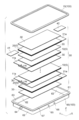
- FIG. 1 is an exploded perspective view of a lithium ion secondary battery according to a first embodiment of the present invention.
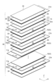
- 1 is an exploded perspective view of an electrode group of a lithium ion secondary battery according to a first embodiment of the present invention.
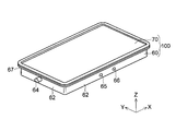
- 1 is an overall perspective view of a lithium ion secondary battery according to a first embodiment of the present invention. It is sectional drawing which expanded and showed a part of FIG. It is sectional drawing which showed typically the connection method of the tab electrode in the lithium ion secondary battery by 1st Embodiment of this invention.
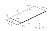
- FIG. 12 is a cross-sectional view of the positive electrode of the lithium ion secondary battery according to the first embodiment of the present invention (a view corresponding to a cross section taken along line AA in FIG. 10). It is a top view of the positive electrode of the lithium ion secondary battery by 1st Embodiment of this invention.
- 1 is a perspective view of a positive electrode of a lithium ion secondary battery according to a first embodiment of the present invention. It is the top view which showed typically a part of positive electrode used for the lithium ion secondary battery by 1st Embodiment of this invention.
- FIG. 17 is a cross-sectional view of the negative electrode of the lithium ion secondary battery according to the first embodiment of the present invention (a diagram corresponding to a cross section taken along line BB in FIG. 16). It is a top view of the negative electrode of the lithium ion secondary battery by 1st Embodiment of this invention.
- 1 is a perspective view of a negative electrode of a lithium ion secondary battery according to a first embodiment of the present invention.
- 1 is a perspective view of a separator of a lithium ion secondary battery according to a first embodiment of the present invention.
- FIG. 1 is a cross-sectional view schematically showing an electrode group of a lithium ion secondary battery according to a first embodiment of the present invention.
- FIG. 2 is an exploded perspective view of the lithium ion secondary battery according to the first embodiment of the present invention.
- FIG. 3 is an exploded perspective view of an electrode group of the lithium ion secondary battery according to the first embodiment of the present invention.
- 4 to 16 are views for explaining the lithium ion secondary battery according to the first embodiment of the present invention.
- the lithium ion secondary battery according to the first embodiment is a large-sized secondary battery having a square flat shape as shown in FIGS.
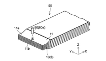
- the lithium ion secondary battery includes an electrode group 50 (see FIGS. 1 and 2) including a plurality of electrodes 5 and a metal outer container 100 that encloses the electrode group 50 together with a non-aqueous electrolyte.
- the electrode 5 includes a positive electrode 10 and a negative electrode 20. Between the positive electrode 10 and the negative electrode 20, a separator 30 for suppressing a short circuit between the positive electrode 10 and the negative electrode 20 is disposed. Specifically, the positive electrode 10 and the negative electrode 20 are arranged so as to face each other with the separator 30 interposed therebetween, and the positive electrode 10, the separator 30, and the negative electrode 20 are sequentially laminated to form a laminated structure (laminated body). Has been. Note that the positive electrodes 10 and the negative electrodes 20 are alternately stacked one by one. The electrode group 50 is configured such that one positive electrode 10 is positioned between two adjacent negative electrodes 20.
- the electrode group 50 includes, for example, 13 positive electrodes 10, 14 negative electrodes 20, and 28 separators 30, and the positive electrodes 10 and the negative electrodes 20 are alternately stacked with the separators 30 interposed therebetween. Further, a separator 30 is disposed on the outermost side of the electrode group 50 (outside of the outermost negative electrode 20), and insulation from the outer container 100 is achieved.
- the positive electrode 10 and the negative electrode 20 are connected to tab electrodes 41 and 42 for drawing out wiring, respectively.
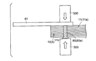
- the tab electrode 41 connected to the positive electrode 10 is electrically connected to the positive electrode 10 via a conductive member (conductive material) 80 made of a low melting point metal.
- the low melting point metal constituting the conductive member 80 is made of a metal material that melts due to the heat generated inside the battery.
- the electrically-conductive member 80 is comprised by the penetration member 80a which penetrates the said positive electrode 10 (electrode) in the thickness direction.
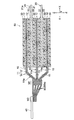
- the positive electrode 10 constituting the electrode group 50 has a structure in which the positive electrode active material layer 12 is supported on both surfaces of the positive electrode current collector 11 as shown in FIG.
- the positive electrode current collector 11 has a function of collecting current from the positive electrode active material layer 12.
- the positive electrode current collector 11 has a multilayer structure (three-layer structure) in which the conductive layers 14 are formed on both surfaces of the insulating resin layer 13.
- the resin layer 13 is an example of the “insulating layer” in the present invention.
- the conductive layer 14 constituting the positive electrode current collector 11 is made of, for example, aluminum or an aluminum alloy, and has a thickness of about 4 ⁇ m to about 10 ⁇ m. Since aluminum is easily passivated, it can be suitably used as the conductive layer 14 of the positive electrode current collector 11.
- the said conductive layer 14 may be other than aluminum or aluminum alloy, for example, may be comprised from metal materials, such as titanium, stainless steel, nickel, or these alloys.
- the method for forming the conductive layer 14 is not particularly limited, and examples thereof include a method by vapor deposition, sputtering, electrolytic plating, electroless plating, bonding of metal foil, and the like, and a method composed of a combination of these methods.
- the resin layer 13 of the positive electrode current collector 11 is made of a plastic material made of a thermoplastic resin.
- This resin layer 13 consists of a sheet-like resin member (resin film), for example.
- the thermoplastic resin constituting the plastic material for example, polyolefin resins such as polyethylene (PE) and polypropylene (PP) having a heat distortion temperature of 150 ° C. or less, polystyrene (PS), polyvinyl chloride, polyamide, etc. are suitable. Used for.
- polyolefin resins such as polyethylene (PE) and polypropylene (PP), which have a heat shrinkage rate at 120 ° C. of 1.5% or more in any direction in the plane direction, and polyvinyl chloride are preferable.
- these composite films and the resin film which gave these surface treatment processes can also be used suitably.
- a resin film made of the same material as that of the separator 30 can be used.
- any resin having different heat deformation temperature, heat shrinkage rate, etc. can be used for both the resin layer 13 and the separator 30 due to differences in manufacturing process and processing.
- the thickness of the resin layer 13 is not particularly limited, but is preferably 5 ⁇ m or more and 70 ⁇ m or less, and more preferably 10 ⁇ m or more and 50 ⁇ m or less in order to balance the energy density improvement and strength maintenance as a secondary battery.
- the resin layer 13 (resin film) may be a resin film manufactured by any method such as uniaxial stretching, biaxial stretching, or non-stretching.
- the resin layer 13 of the positive electrode current collector 11 may be, for example, in the form of a fiber other than a film.
- the positive electrode current collector 11 has a film shape, a sheet shape, a net shape, a punched or expanded shape, a lath body, a porous body, a foamed body, a formed body of fiber groups, and the like. Also good.
- the above heat deformation temperature and heat shrinkage mean values obtained by the following method.
- the heat deformation temperature means a temperature at which the resin layer (resin film) starts to shrink (the same applies to the separator described later).
- the heat distortion temperature is kept at a constant temperature for a certain time in a thermostatic chamber, the heat shrinkage rate is measured, the temperature is increased if not contracted, the temperature is decreased if contracted, and this is repeated.
- the resin film is held at, for example, 100 ° C. for 15 minutes, and the thermal shrinkage rate of the resin film is measured.
- the heat shrinkage rate at this time is 20% or less
- the temperature is raised to 105 ° C. using a new sample, and the heat shrinkage rate is measured after holding at this temperature for 15 minutes. This process is repeated until the temperature reaches 150 ° C., and the temperature at which the heat shrinkage rate becomes 10% or more is defined as the heat distortion temperature.
- the heat shrinkage rate is measured, for example, by attaching two points on the resin film with an interval of 50 mm or more and measuring the distance between the two points using a caliper. Then, after heat-processing for 15 minutes at 120 degreeC (180 degreeC also about the separator mentioned later), the same distance between points is measured again, and a thermal contraction rate is calculated
- the distance between three or more points is measured for each of the plane directions (for example, the vertical direction and the horizontal direction) of the resin layer (resin film). And the average value of the thermal contraction rate computed from each measurement result is employ
- the longitudinal direction and the lateral direction of the resin film at least two points within 10% from the end of the resin film and one point around 50% from the end of the resin film are measured points of the distance between points.
- Select as Any large value in the plane direction (for example, the vertical direction and the horizontal direction) is defined as the heat shrinkage rate.
- the positive electrode active material layer 12 includes a positive electrode active material that can occlude and release lithium ions.
- the positive electrode active material include an oxide containing lithium. Specific examples include LiCoO 2 , LiFeO 2 , LiMnO 2 , LiMn 2 O 4 , and compounds in which transition metals in these oxides are partially substituted with other metal elements.
- a positive electrode active material that can utilize 80% or more of the lithium amount possessed by the positive electrode for the battery reaction. Thereby, it becomes possible to improve the safety of the secondary battery against accidents such as overcharging.
- a positive electrode active material for example, a compound having a spinel structure such as LiMn 2 O 4 and Li X MPO 4 (M is at least one selected from Co, Ni, Mn, and Fe). And a compound having an olivine structure represented by (element).
- a positive electrode active material containing at least one of Mn and Fe is preferable from the viewpoint of cost.
- LiFePO 4 from the viewpoint of safety and charging voltage. In LiFePO 4 , since all oxygen (O) is bonded to phosphorus (P) by a strong covalent bond, release of oxygen due to a temperature rise hardly occurs. Therefore, it is excellent in safety.
- the thickness of the positive electrode active material layer 12 is preferably about 20 ⁇ m to 2 mm, and more preferably about 50 ⁇ m to 1 mm.
- the configuration of the positive electrode active material layer 12 is not particularly limited as long as it includes at least the positive electrode active material.
- the positive electrode active material layer 12 may include other materials such as a conductive material, a thickener, and a binder in addition to the positive electrode active material.
- the conductive material is not particularly limited as long as it is an electron conductive material that does not adversely affect the battery performance of the positive electrode 10.
- carbon black, acetylene black, ketjen black, graphite (natural graphite, artificial graphite), carbonaceous material such as carbon fiber, or conductive metal oxide can be used as the conductive material.
- carbon black and acetylene black are preferable from the viewpoints of electron conductivity and coatability.
- the thickener for example, polyethylene glycols, celluloses, polyacrylamides, poly N-vinyl amides, poly N-vinyl pyrrolidones and the like can be used.
- celluloses such as polyethylene glycols and carboxymethyl cellulose (CMC) are preferable, and CMC is particularly preferable.
- the binder plays a role of holding the active material particles and the conductive material particles together.
- the binder for example, fluorine-based polymers such as polyvinylidene fluoride (PVDF), polyvinyl pyridine, and polytetrafluoroethylene, polyolefin-based polymers such as polyethylene and polypropylene, styrene-butadiene rubber, and the like can be used.
- Examples of the solvent for dispersing the positive electrode active material, the conductive material, the binder, etc. include N-methyl-2-pyrrolidone, dimethylformamide, dimethylacetamide, methyl ethyl ketone, cyclohexanone, methyl acetate, methyl acrylate, diethyltriamine, N, Organic solvents such as N-dimethylaminopropylamine, ethylene oxide, and tetrahydrofuran can be used.
- the positive electrode 10 described above is prepared by mixing a positive electrode active material, a conductive material, a thickener and a binder, and adding an appropriate solvent to form a paste-like positive electrode mixture.
- the positive electrode mixture is applied and dried on the surface of the positive electrode current collector 11, and is compressed to increase the electrode density as necessary.
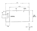
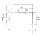
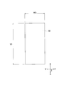
- the positive electrode 10 has a substantially rectangular shape in plan view.
- the width W1 in the Y direction of the positive electrode 10 is about 100 mm, for example, and the length L1 in the X direction is about 150 mm, for example.
- the width W11 in the Y direction is the same as the width W1 of the positive electrode 10 (for example, about 100 mm), and the length L11 in the X direction is about 135 mm, for example. It is said that.
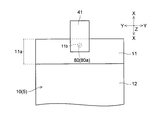
- the positive electrode 10 has a current collector in which the surface (conductive layer 14) of the positive electrode current collector 11 is exposed without forming the positive electrode active material layer 12 on one end side in the X direction. It has an exposed portion (exposed region) 11a.
- a tab electrode 41 for taking out a current to the outside is electrically connected to the current collector exposed portion 11a.
- the tab electrode 41 is formed in a shape having a width of about 30 mm and a length of about 70 mm, for example.
- the current collector exposed portion 11a of the positive electrode 10 is formed with a through hole 11b penetrating in the thickness direction.
- the through holes 11b are formed so that the through holes 11b of the respective positive electrodes 10 are aligned (overlap) when a plurality of the positive electrodes 10 are laminated.
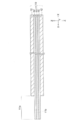
- the conductive member 80 (through member 80a) (see FIG. 1) formed in a substantially rod shape is inserted into the through hole 11b of the positive electrode 10.
- the negative electrode 20 constituting the electrode group 50 has a configuration in which a negative electrode active material layer 22 is supported on both surfaces of a negative electrode current collector 21, as shown in FIG.
- the negative electrode current collector 21 has a function of collecting current from the negative electrode active material layer 22.
- the negative electrode current collector 21 does not include a resin layer. That is, only the positive electrode current collector 11 (see FIG. 8) has a multilayer structure including a resin layer.
- the negative electrode current collector 21 is made of, for example, a metal foil such as copper, nickel, stainless steel, iron, or a nickel plating layer, or an alloy foil made of these alloys.
- the thickness of the negative electrode current collector 21 is formed to be about 1 ⁇ m to about 100 ⁇ m (for example, about 16 ⁇ m).
- the negative electrode current collector 21 is preferably a metal foil made of copper or a copper alloy from the viewpoint that it is difficult to alloy with lithium, and the thickness thereof is preferably 4 ⁇ m or more and 20 ⁇ m or less.
- the negative electrode current collector 21 has a film shape, a sheet shape, a net shape, a punched or expanded shape, a lath body, a porous body, a foamed body, a formed body of fiber groups, and the like. Also good.
- the negative electrode active material layer 22 includes a negative electrode active material that can occlude and release lithium ions.
- a negative electrode active material for example, a material containing lithium or a material capable of occluding and releasing lithium is used.
- the potential for insertion / extraction of lithium is close to the deposition / dissolution potential of metallic lithium.
- Typical examples thereof include particulate natural graphite or artificial graphite (scale-like, lump-like, fibrous, whisker-like, spherical, pulverized particle-like, etc.).
- the negative electrode active material artificial graphite obtained by graphitizing mesocarbon microbeads, mesophase pitch powder, isotropic pitch powder, or the like may be used. Further, graphite particles having amorphous carbon attached to the surface can also be used. Furthermore, lithium transition metal oxides, lithium transition metal nitrides, transition metal oxides, silicon oxides, and the like can also be used. As the lithium transition metal oxide, for example, when lithium titanate represented by Li 4 Ti 5 O 12 is used, the deterioration of the negative electrode 20 is reduced, so that the battery life can be extended.
- the thickness of the negative electrode active material layer 22 is preferably about 20 ⁇ m to 2 mm, and more preferably about 50 ⁇ m to 1 mm.
- the configuration of the negative electrode active material layer 22 is not particularly limited as long as it includes at least the negative electrode active material.
- the negative electrode active material layer 22 may include other materials such as a conductive material, a thickener, and a binder in addition to the negative electrode active material.
- a conductive material, a thickening material, and a binder can be the same as the positive electrode active material layer 12 (that can be used for the positive electrode active material layer 12).
- the negative electrode 20 described above is mixed with a negative electrode active material, a conductive material, a thickener and a binder, and an appropriate solvent is added to obtain a paste-like negative electrode mixture.
- This negative electrode mixture is applied and dried on the surface of the negative electrode current collector 21, and is compressed to increase the electrode density as necessary.
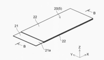
- the negative electrode 20 has a substantially rectangular shape in plan view, and is formed to be slightly larger than the positive electrode 10 (see FIGS. 9 and 10).
- the negative electrode 20 has a width W2 in the Y direction of about 110 mm, for example, and a length L2 in the X direction is the same as the length L1 of the positive electrode 10 (see FIG. 9) ( For example, about 150 mm).
- the width W21 in the Y direction is the same as the width W2 of the negative electrode 20 (for example, about 110 mm), and the length L21 in the X direction is, for example, about 140 mm. It is said that.
- the negative electrode 20 is a current collector in which the surface of the negative electrode current collector 21 is exposed without forming the negative electrode active material layer 22 at one end in the X direction, like the positive electrode 10. It has an exposed portion 21a.
- a tab electrode 42 for taking out current to the outside is electrically connected to the current collector exposed portion 21a.
- the tab electrode 42 is formed in a shape of, for example, a width of about 30 mm and a length of about 70 mm, similar to the tab electrode 41.
- the separator 30 constituting the electrode group 50 is appropriately selected from, for example, electrically insulating synthetic resin fibers, non-woven fabrics such as glass fibers and natural fibers, woven fabrics, or microporous membranes. Is possible. Among these, non-woven fabrics such as polyethylene, polypropylene, polyester, aramid resins, and cellulose resins, and microporous membranes are preferable from the viewpoint of quality stability, and in particular, non-woven fabrics composed of aramid resins, polyester resins, or cellulose resins. A microporous membrane is preferred.
- the separator 30 preferably has a higher melting point than the resin layer 13 of the positive electrode current collector 11.
- the separator 30 is preferably configured so that the thermal contraction rate at 120 ° C. is smaller than that of the resin layer 13 of the positive electrode current collector 11.
- the separator 30 preferably has a thermal shrinkage rate of 1.0% or less at a temperature not higher than the heat deformation temperature (or melting point) of the resin layer 13 of the positive electrode current collector 11.
- the separator 30 is preferably composed of a porous film containing an aramid resin, a polyester resin, a cellulose resin, etc., and its thermal shrinkage rate is preferably 1.0% or less at 180 ° C.
- the thickness of the separator 30 is not particularly limited, but is a thickness that can hold a necessary amount of electrolyte and can prevent a short circuit between the positive electrode 10 and the negative electrode 20. Is preferred. Specifically, the separator 30 can have a thickness of 0.02 mm (20 ⁇ m) to 0.1 mm (100 ⁇ m), for example. The thickness of the separator 30 is preferably about 0.01 mm to 1 mm, more preferably about 0.02 mm to 0.07 mm. The material constituting the separator 30 is such that the air permeability per unit area (1 cm 2 ) is about 0.1 sec / cm 3 to 500 sec / cm 3 while maintaining a low battery internal resistance. This is preferable because strength sufficient to prevent an internal short circuit can be secured.
- the heat-deformation temperature and heat-shrink rate mean the value obtained by the method similar to the resin layer (resin film) mentioned above.
- heat treatment is performed at 120 ° C.
- heat treatment is performed at 180 ° C.
- the separator 30 is larger than the application region (formation region) of the positive electrode active material layer 12 and is equal to the application region (formation region) of the negative electrode active material layer 22 or the application region (formation region) of the negative electrode active material layer 22.
- the separator 30 is formed in a rectangular shape, and the width W3 in the Y direction is, for example, about 110 mm, and the length L3 in the X direction is, for example, about 150 mm.
- the positive electrode 10 and the negative electrode 20 are arranged such that the current collector exposed portion 11a of the positive electrode 10 and the current collector exposed portion 21a of the negative electrode 20 are positioned on opposite sides. They are stacked with a separator 30 interposed between the negative electrodes.
- the current collector exposed portion 11 a of the stacked positive electrode 10 is electrically conductive through the positive electrode current collector 11 having a multilayer structure in the thickness direction.
- a member 80 (penetrating member 80a) is provided. The conductive member 80 is inserted through the through hole 11 b of the positive electrode current collector 11, thereby continuously passing through all of the stacked positive electrodes 10 (electrodes 5 having the same polarity).
- the conductive member 80 is made of a metal material that melts due to heat generated in the battery.
- a metal material for example, an alloy mainly containing any one of indium, zinc, gallium, tin, and bismuth can be used. Specific examples include a tin-bismuth alloy (melting point: about 130 ° C. to 150 ° C.) and indium (melting point: 156.4 ° C.).
- the conductive member 80 may have a melting point equal to or higher than the melting point of the resin layer 13 of the positive electrode current collector 11, or may have a melting point lower than the melting point of the resin layer 13.
- the through hole 11b of the positive electrode current collector 11 is formed to have the same diameter as that of the conductive member 80 as shown in FIGS.
- the conductive member 80 is inserted into the through hole 11b, so that the surface (outer surface) of the conductive member 80 is in close contact (electrical contact) with the inner side surface of the through hole 11b.
- the conductive layer 14 on one side and the conductive layer 14 on the other side of the resin layer 13 in the positive electrode current collector 11 are electrically connected to each other via the conductive member 80.
- the conductive member 80 continuously penetrates all the positive electrodes 10, all the stacked positive electrodes 10 are electrically connected to each other.
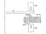
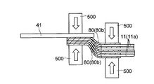
- the conductive member 80 inserted through the through hole 11 b is pressed in the thickness direction (see white arrow) by the welding machine 500, for example, so that the protruding portion of the conductive member 80 is It is crushed and squeezed.
- the tab electrode 41 for wiring connection is electrically connected to each of the positive electrodes 10 via the conductive member 80.
- the conductive member 80 that electrically connects the tab electrode 41 and the positive electrode 10 is provided at one location of the current collector exposed portion 11a of the positive electrode current collector 11, as shown in FIGS. Also good. Further, the conductive member 80 may be provided at a plurality of locations on the current collector exposed portion 11a. Thus, by providing (penetrating) the conductive member 80 at a plurality of locations on the current collector exposed portion 11a, the contact resistance between the positive electrodes is reduced, so that the conduction between the electrodes (between the positive electrodes) is improved.
- the above-described tab electrode 41 is welded and fixed to the outermost positive electrode 10 (the conductive layer 14 of the positive electrode current collector 11) via a conductive member 80 made of a low melting point metal.
- the tab electrode 41 may be welded to the positive electrode 10 of the intermediate layer instead of the outermost layer.
- the tab electrode 41 is welded and fixed so as to overlap the conductive member 80 at a substantially central portion in the width direction (Y direction) of the positive electrode current collector 11 (positive electrode 10). Yes. Thereby, all the laminated positive electrodes 10 (all the conductive layers 14) are electrically connected to the tab electrode 41 through the conductive member 80.
- the tab electrode 41 is connected to the electrode (positive electrode 10) via the conductive member 80, the conductive member 80 is blown when abnormal heat is generated inside the battery. The current is cut off.
- the plurality of negative electrodes 20 are laminated so that the current collector exposed portions 21a are aligned, as with the positive electrode 10.
- the tab electrode 42 is fixed by welding to the outermost negative electrode 20 (negative electrode current collector 21).
- the tab electrode 42 may be welded to the negative electrode 20 of the intermediate layer instead of the outermost layer. Thereby, all the laminated negative electrodes 20 are welded and fixed to the tab electrode 42 and are electrically connected to the tab electrode 42.
- the tab electrode 42 is welded and fixed to a substantially central portion in the width direction (Y direction) of the negative electrode current collector 21 (negative electrode 20).
- the welding of the tab electrodes 41 and 42 is preferably ultrasonic welding, but may be other than ultrasonic welding, for example, laser welding, resistance welding, spot welding, or the like may be used.
- the resin layer 13 may be dissolved by a method of joining by applying heat such as laser welding, resistance welding, or spot welding. There is. Therefore, it is preferable to use ultrasonic welding without applying heat for the welding of the tab electrode 41.
- the tab electrode 41 connected to the positive electrode 10 is preferably made of aluminum, and the tab electrode 42 connected to the negative electrode 20 is preferably made of copper.
- the tab electrodes 41 and 42 are preferably made of the same material as the current collector, but may be made of different materials. Further, the tab electrode 41 connected to the positive electrode 10 and the tab electrode 42 connected to the negative electrode 20 may be made of the same material or different materials.
- the tab electrodes 41 and 42 are preferably welded to substantially the center portion in the width direction of the positive electrode current collector 11 and the negative electrode current collector 21 as described above, but are fixed to the regions other than the center portion by welding. May be.
- the nonaqueous electrolytic solution enclosed with the electrode group 50 in the outer container 100 is not particularly limited, but examples of the solvent include ethylene carbonate (EC), propylene carbonate, butylene carbonate, and diethyl.
- Esters such as carbonate (DEC), dimethyl carbonate, methyl ethyl carbonate, ⁇ -butyrolactone, ethers such as tetrahydrofuran, 2-methyltetrahydrofuran, dioxane, dioxolane, diethyl ether, dimethoxyethane, diethoxyethane, methoxyethoxyethane, Polar solvents such as dimethyl sulfoxide, sulfolane, methyl sulfolane, acetonitrile, methyl formate, and methyl acetate can be used. These solvents may be used alone, or two or more kinds may be mixed and used as a mixed solvent.
- the nonaqueous electrolytic solution may contain an electrolyte supporting salt.
- the electrolyte supporting salt include LiClO 4 , LiBF 4 (lithium borofluoride), LiPF 6 (lithium hexafluorophosphate), LiCF 3 SO 3 (lithium trifluoromethanesulfonate), LiF (lithium fluoride), LiCl
- lithium salts such as (lithium chloride), LiBr (lithium bromide), LiI (lithium iodide), LiAlCl 4 (lithium tetrachloride aluminate). These may be used singly or in combination of two or more.
- the concentration of the electrolyte supporting salt is not particularly limited, but is preferably 0.5 mol / L to 2.5 mol / L, more preferably 1.0 mol / L to 2.2 mol / L.
- concentration of the electrolyte support salt is less than 0.5 mol / L, the carrier concentration for carrying charges in the non-aqueous electrolyte is lowered, and the resistance of the non-aqueous electrolyte may be increased.
- the concentration of the electrolyte supporting salt is higher than 2.5 mol / L, the dissociation degree of the salt itself is lowered, and there is a possibility that the carrier concentration in the non-aqueous electrolyte does not increase.
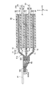
- the exterior container 100 that encloses the electrode group 50 is a large flat rectangular container, and an exterior can 60 that houses the electrode group 50 and the like, and a sealing plate 70 that seals the exterior can 60. It is comprised including. Further, a sealing plate 70 is attached to the outer can 60 containing the electrode group 50 by, for example, laser welding.
- the outer can 60 is formed by, for example, deep drawing processing or the like on a metal plate, and is formed in a substantially box shape having a bottom surface portion 61 and a side wall portion 62. As shown in FIG. 2, an opening 63 for inserting the electrode group 50 is provided at one end of the outer can 60 (opposite the bottom surface portion 61).
- the outer can 60 is formed in a size that can be accommodated such that the electrode surface of the electrode group 50 faces the bottom surface portion 61.
- the outer can 60 has an electrode terminal 64 (for example, a positive electrode terminal) formed on a side wall 62 on one side (short side) in the X direction, and the other in the X direction.
- An electrode terminal 64 (for example, a negative electrode terminal) is formed on the side wall portion 62 on the side (short side).
- a liquid injection hole 65 for injecting a nonaqueous electrolytic solution is formed in the side wall 62 of the outer can 60.
- the liquid injection hole 65 is formed in a size of ⁇ 2 mm, for example.
- a safety valve 66 for releasing the battery internal pressure is formed in the vicinity of the liquid injection hole 65.
- a folded portion 67 is provided at the periphery of the opening 63 of the outer can 60, and the sealing plate 70 is fixed to the folded portion 67 by welding.
- the outer can 60 and the sealing plate 70 can be formed using, for example, a metal plate such as iron, stainless steel, or aluminum, or a steel plate obtained by applying nickel plating to iron. Since iron is an inexpensive material, it is preferable in terms of price, but in order to ensure long-term reliability, it is better to use a metal plate made of stainless steel, aluminum, etc. or a steel plate with iron plated with nickel. preferable.
- the thickness of the metal plate can be, for example, about 0.4 mm to about 1.2 mm (eg, about 1.0 mm).
- the electrode group 50 described above is housed in the outer can 60 such that the positive electrode 10 and the negative electrode 20 face the bottom surface portion 61 of the outer can 60.
- the current collector exposed portion 11a of the positive electrode 10 and the current collector exposed portion 21a of the negative electrode 20 are electrically connected to the electrode terminal 64 of the outer can 60 through the tab electrodes 41 and 42, respectively. ing.
- the nonaqueous electrolytic solution is injected under reduced pressure from the injection hole 65 after the opening 63 of the outer can 60 is sealed by the sealing plate 70, for example. Then, after a metal sphere having a diameter substantially the same as the liquid injection hole 65 or a metal plate (not shown) slightly larger than the liquid injection hole 65 is installed in the liquid injection hole 65, the liquid injection hole 65 is formed by resistance welding or laser welding. It is sealed.
- a current collector having a multilayer structure is used for the positive electrode current collector 11 as described above. For this reason, for example, when a local short circuit occurs between the electrodes, the resin layer 13 of the positive electrode current collector 11 is melted and the electrode (positive electrode 10) is damaged, so that the current can be cut. Thereby, since the temperature rise inside a battery can be suppressed, it can prevent that abnormal states, such as ignition, arise.
- the tab electrode 41 is electrically connected to the current collector exposed portion 11a of the positive electrode 10 through the conductive member 80 (penetrating member 80a) made of a low melting point metal. For this reason, when the temperature inside the battery rises due to some cause such as an overcharged state, the conductive member 80 (penetrating member 80a) can be melted at the temperature inside the battery. Thereby, the electrical connection between the tab electrode 41 and the electrode (positive electrode 10) can be cut off.
- the current can be interrupted not only by the current collector 11 having a multilayer structure, but also by the conductive member 80 that connects the tab electrode 41 and the electrode (positive electrode 10). Safety can be further improved.
- the current can be interrupted by the positive electrode current collector 11 having a multilayer structure as described above. Can be suppressed.
- the positive electrode current collector 11 having a multilayer structure may be difficult for the positive electrode current collector 11 having a multilayer structure to suppress the temperature rise inside the battery.
- the internal current can be cut off by fusing the conductive member 80 by heat generation inside the battery, a temperature rise inside the battery can be suppressed.
- the tab electrode 41 (conductive member 80) connected to the stacked positive electrode 10 is a portion through which a total current flows, and thus the flowing current is large. Therefore, when an abnormal current flows, the amount of heat generated by the resistance also increases, so that the conductive member 80 can be melted by the heat. For this reason, even when an abnormal current flows, the current can be interrupted.
- the conductive member 80 is provided inside the battery (near the electrode), the current interruption function by the conductive member 80 can be effectively activated against abnormal heat generation inside the battery.
- a current interruption mechanism such as a PTC (Positive Temperature Coefficient) element is provided outside the battery, it becomes difficult to detect abnormal heat generation inside the battery.
- the electrically-conductive member 80 is provided in the inside of a battery, the abnormal heat_generation
- the conductive member 80 is made of a low melting point metal (metal material) that melts due to heat generated in the battery, abnormal heat generation of the battery can be easily suppressed, so that safety is further improved. An improved lithium ion secondary battery can be easily obtained.
- the positive electrode current collector 11 has a configuration (multilayer structure) in which the resin layer 13 is sandwiched between the conductive layers 14, when a plurality of electrodes are stacked as described above, the tab electrode 41 for wiring extraction is provided.
- the electrodes cannot conduct each other. For this reason, when the collector which has a multilayer structure is used in order to improve safety, the problem that battery performance falls will arise.
- the conductive member 80 as the penetrating member 80a, the conductive layer 14 on one side of the resin layer 13 in the positive electrode current collector 11 via the conductive member 80 (penetrating member 80a)
- the other conductive layer 14 can be electrically connected.
- the current collector (positive electrode current collector 11) having a multilayer structure was used by continuously penetrating all of the plurality of positive electrodes 10 (positive electrode current collector 11) on which the penetrating member 80a was laminated. Even in this case, conduction between the stacked electrodes can be achieved. Thereby, the tab electrode 41 can be electrically connected to all of the plurality of stacked electrodes (positive electrode 10). Therefore, since the deterioration of battery performance can be suppressed, the performance of the lithium ion secondary battery can be fully utilized.
- the conductive member 80 by providing the conductive member 80, for example, when the tab electrode 41 is connected to the electrode (positive electrode 10) by ultrasonic welding, the contact between the tab electrode 41 and the electrode (positive electrode 10). Resistance and contact resistance between electrodes can be reduced. Thereby, the tab electrode 41 can be firmly connected to the electrode (positive electrode 10). In addition, by firmly connecting the tab electrode 41 to the electrode (positive electrode 10), it is possible to suppress a decrease in battery capacity due to an increase in contact resistance.
- the conductive member 80 is easily formed in the thickness direction of the current collector by previously forming the through hole 11b through which the conductive member 80 (through member 80a) is inserted in the positive electrode current collector 11. Can be penetrated. Thereby, the conductive layer 14 on one side of the resin layer 13 in the positive electrode current collector 11 and the conductive layer 14 on the other side can be easily electrically connected.
- the conductive member 80 made of a low melting point metal is configured to have a melting point equal to or higher than the melting point of the resin layer 13 of the positive electrode current collector 11, it is difficult to prevent the current collector 11 having a multilayer structure. Abnormal heat generation inside can be prevented by fusing the conductive member 80. Thereby, safety can be improved more easily.
- the conductive member 80 made of a low melting point metal is configured to have a melting point lower than the melting point of the resin layer 13 of the positive electrode current collector 11, the conductive member 80 may be removed before the resin layer 13 of the positive electrode current collector 11 melts. Can be blown. For this reason, even when comprised in this way, the safety
- the resin layer 13 of the positive electrode electrical power collector 11 is comprised from a thermoplastic resin, and the thermal contraction rate in 120 degreeC is in any direction of a plane direction (for example, the vertical direction and a horizontal direction). It is configured to be 1.5% or more.
- the resin layer 13 of the positive electrode current collector 11 is formed of a polyolefin resin such as polyethylene or polypropylene, the safety of the lithium ion secondary battery can be easily improved.
- the resin layer 13 may be formed of a resin containing any of polystyrene, polyvinyl chloride, and polyamide. Moreover, you may form the resin layer 13 with the composite material of said each resin.
- the separator 30 is configured such that the thermal shrinkage rate at 120 ° C. is smaller than that of the resin layer 13 of the positive electrode current collector 11. Thereby, before the shutdown function of the separator 30 act
- the thermal contraction rate of the separator 30 at 180 ° C. is 1.0% or less, an internal short circuit (electrical current) caused by the thermal contraction of the separator 30 when abnormal heat generation occurs in an overcharged state or a high temperature state. It is possible to suppress the occurrence of internal short circuit of the battery that occurs at the extreme part. For this reason, it is possible to suppress an abrupt increase in temperature. As a result, the safety of the lithium ion secondary battery can be further improved.
- the melting / fluidization of the separator 30 can be suppressed even at a temperature of 180 ° C., resulting in a disadvantage that the pores of the separator 30 are enlarged due to the melting / fluidization. Can be suppressed. For this reason, when the inside of the battery reaches 180 ° C., even if the electrode (positive electrode 10) is not damaged for some reason, the short-circuited portion of the positive and negative electrodes is caused by the large hole in the separator 30. It is also possible to suppress the inconvenience of spreading.
- FIG. 17 is a cross-sectional view schematically showing an electrode group of the lithium ion secondary battery according to the second embodiment of the present invention.
- FIG. 18 is a perspective view schematically showing a part of the electrode group of the lithium ion secondary battery according to the second embodiment of the present invention.
- 19 and 20 are cross-sectional views illustrating a lithium ion secondary battery according to a second embodiment of the present invention.
- a lithium ion secondary battery according to a second embodiment of the invention will be described.
- symbol is attached
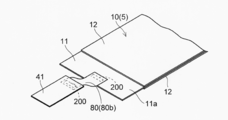
- a conductive member 80 made of a low melting point metal is composed of a metal foil 80b.
- the conductive member 80 is disposed between each of the stacked positive electrode current collectors 11.
- the plurality of conductive members 80 formed in a foil shape are arranged so as to extend (extend) to the outside of the positive electrode current collector 11 (on the side opposite to the active material layer 12).
- the conductive member 80 is formed in a substantially strip shape (band shape), and the conductive member 80 is arranged so as to be shifted in the X direction. Thereby, the conductive member 80 extends (extends) to the outside of the positive electrode current collector 11.
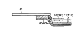
- the plurality of conductive members 80 collect current from the positive electrode 10 (the positive electrode current collector 11) in a portion (welding region M ⁇ b> 1) disposed between the positive electrode current collectors 11. It is fixed to the body exposed portion 11a by welding. Each extending portion of the plurality of conductive members 80 is fixed to the tab electrode 41 by welding. That is, one end of the conductive member 80 is welded and fixed to the positive electrode 10 in the welding region M1, and the other end of the conductive member 80 is welded and fixed to the tab electrode 41 in the welding region M2.
- the conductive member 80 when one end portion of the conductive member 80 is pressed together with the positive electrode current collector 11 in the thickness direction (see the white arrow) by, for example, a welding machine 500, the conductive member 80 and the positive electrode The current collector 11 (current collector exposed portion 11a) is fixed by welding. Further, the other end of the conductive member 80 is pressed together with the tab electrode 41 in the thickness direction (see the white arrow) by the welding machine 500, for example, so that the conductive member 80 and the tab electrode 41 are fixed by welding. Thereby, the tab electrode 41 for drawing out the wiring is in a state of being electrically connected to the current collector exposed portion 11a of the positive electrode 10 through the conductive member 80 made of a low melting point metal. Moreover, as shown in FIG. 18, the welding location 200 is in the state where it was dented with the pressure at the time of welding.
- the foil-like conductive member 80 is not only between the positive electrode current collectors 11 but also the outermost (uppermost layer, lowermost layer) positive electrode 10 (conductivity of the positive electrode current collector 11). It is also preferably arranged in layer 14).
- the thickness of the conductive member 80 (metal foil 80b) is not particularly limited, but is preferably about 0.05 mm to about 0.5 mm, for example.
- the through hole 11b through which the penetrating member is inserted into the positive electrode current collector 11 see FIG. 3). Is not provided.
- the tab electrode 41 is electrically connected to the electrode (positive electrode 10) through the foil-like conductive member 80 made of a low melting point metal as described above.
- the electrically-conductive member 80 can be blown by the temperature inside the battery. For this reason, the electrical connection between the tab electrode 41 and the electrode (positive electrode 10) can be cut off.
- a foil-like conductive member 80 made of a low-melting-point metal is disposed between the positive electrode current collectors 11 (current collector exposed portions 11a) in the stacked positive electrodes 10.
- the conductive layer 14 of each positive electrode current collector 11 can be electrically connected to the tab electrode 41 via the conductive member 80.
- all of the positive electrodes 10 can be electrically connected to the tab electrode 41, thereby suppressing a decrease in battery performance. Can do. As a result, the performance of the lithium ion secondary battery can be maximized.
- FIG. 21 is a cross-sectional view schematically showing an electrode group of the lithium ion secondary battery according to the third embodiment of the present invention.
- 22 and 23 are diagrams for explaining a lithium ion secondary battery according to a third embodiment of the present invention.
- a lithium ion secondary battery according to a third embodiment of the invention will be described with reference to FIGS.
- symbol is attached
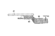
- the metal foil 90 disposed between the positive electrode current collectors 11 is made of a metal material other than the low melting point metal. ing.
- the metal foil 90 is welded to the tab electrode 41 by a conductive member 80 made of a low melting point metal.
- all metal foils 90 are joined to the tab electrode 41 using a block-shaped conductive member 80 (80c).
- the tab electrode 41 for drawing out the wiring is electrically connected to the current collector exposed portion 11a of the positive electrode 10 through the conductive member 80 made of a low melting point metal.
- the metal foil 90 is an example of the “foil-like member” in the present invention.
- ultrasonic welding or resistance welding can be used for welding the tab electrode 41.
- the metal foil 90 is made of, for example, aluminum or an aluminum alloy.
- the metal foil 90 may be other than aluminum or an aluminum alloy, and may be made of, for example, a metal material such as titanium, stainless steel, or nickel, or an alloy thereof.
- the thickness of the metal foil 90 is not particularly limited, but is preferably about 0.05 mm to about 0.5 mm, for example.
- the metal foil 90 is connected to the positive electrode 10 so that a part of the metal foil 90 extends outside the electrode (positive electrode 10), and the extended part of the metal foil 90 is a low melting point metal. It welds to the tab electrode 41 with the electrically-conductive member 80 which consists of. Thereby, the tab electrode 41 can be electrically connected to the electrode (positive electrode 10) via the conductive member 80. For this reason, when the temperature inside the battery rises due to some cause such as an overcharged state, the conductive member 80 can be melted at the temperature inside the battery. Thereby, the electrical connection between the tab electrode 41 and the electrode (positive electrode 10) can be cut off.
- the metal foil 90 is disposed between the positive electrode current collectors 11 (current collector exposed portions 11 a) in the stacked positive electrodes 10, and a part of the metal foil 90 is used as the tab electrode 41. Weld. Thereby, the conductive layer 14 of each positive electrode current collector 11 can be electrically connected to the tab electrode 41 via the conductive member 80. For this reason, even when a current collector having a multilayer structure (positive electrode current collector 11) is used, all of the positive electrodes 10 can be electrically connected to the tab electrode 41, thereby suppressing a decrease in battery performance. Can do. As a result, the performance of the lithium ion secondary battery can be maximized.
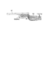
- Modification of the third embodiment 24 and 25 are cross-sectional views schematically showing an electrode group of a lithium ion secondary battery according to a modification of the third embodiment.
- a conductive member (conductive material) 80 (80d) made of a low melting point metal is melted to obtain a metal foil.
- 90 is joined to the tab electrode 41.
- the metal foil 90 is joined to the tab electrode 41 in the manner of soldering.
- the present invention is not limited thereto.
- the present invention may be applied to non-aqueous secondary batteries other than lithium ion secondary batteries.
- the present invention can also be applied to non-aqueous secondary batteries that will be developed in the future.
- the present invention is not limited to this, and for example, windings other than the stacked type
- the present invention may be applied to a rechargeable secondary battery.
- a film-like resin layer is used as the resin layer (insulating layer) of the current collector, but the present invention is not limited to this.
- a fibrous resin layer may be used. Examples of the fibrous resin layer include a layer made of woven fabric or non-woven fabric.
- the current collector on the positive electrode side is configured in a multilayer structure including the resin layer and the conductive layer.
- the present invention is not limited to this, and the negative electrode
- the current collector on the side may be configured in a multilayer structure including a resin layer and a conductive layer.
- both the positive electrode and the negative electrode may be formed using a current collector having a multilayer structure (three-layer structure), or one of the positive electrode and the negative electrode is used as a current collector having a multilayer structure (three-layer structure). May be formed.
- the positive electrode side is preferably formed using a current collector having a multilayer structure (three-layer structure). .
- the conductive layer is preferably made of copper or a copper alloy. Specifically, it is preferable to use a copper foil or a copper alloy foil having a thickness of about 4 ⁇ m to about 10 ⁇ m as the conductive layer.
- the conductive layer of the negative electrode current collector may be other than copper or a copper alloy, and may be composed of, for example, nickel, stainless steel, iron, or an alloy thereof.
- the resin layer of the negative electrode current collector may be the same as the resin layer of the positive electrode current collector (that can be used for the resin layer of the positive electrode current collector 11).
- the current collector on the negative electrode side has a multi-layer structure
- a plurality of stacked electrodes are provided in the same manner as the positive electrode (positive current collector) shown in the first to third embodiments (including modifications). It is preferable that the (negative electrode) and the tab electrode are configured to be electrically connected via a conductive member.
- a material that can be melted at a desired temperature can be appropriately used as the low melting point metal constituting the conductive member.
- the conductive member (conductive material) is made of a low melting point metal.
- the resistance of the conductive member increases according to temperature change. You may comprise from the material to do.
- the conductive member may be made of a PTC material.
- the conductive member may be, for example, a temperature sensitive element such as a bimetal, a fuse, or the like.
- the tab electrode and all the stacked electrodes (positive electrodes) are electrically connected via the conductive member.
- the present invention is not limited to this.
- the tab electrode and at least some of the electrodes (conductive layer) may be electrically connected via a conductive member.
- a portion of the tab electrode 41 is connected to the uppermost positive electrode 10 (the current collector exposed portion 11a of the positive electrode current collector 11) as shown in FIG. It can also be configured.
- the tab electrode 41 is connected to the uppermost positive electrode 10.
- the positive electrode current collector 11 has a multilayer structure having the resin layer 13, the electrical connection with the lower layer positive electrode 10 is interrupted. For this reason, even when comprised in this way, safety
- the connection strength of the tab electrode 41 can be improved, durability and vibration resistance can also be improved.
- part of the tab electrode 41 is connected to the uppermost positive electrode 10 (the current collector exposed portion 11a of the positive electrode current collector 11). Can be configured. The same applies to the configuration of the first embodiment.
- the present invention is not limited to this, and the shape of the outer container is used. May be other than a flat square.
- the outer container may be a thin flat tube type, a cylindrical type, a rectangular tube type, or the like.
- the outer container may be an outer container using a laminated sheet, for example, in addition to a metal can.
- the negative electrode (negative electrode active material layer) is larger than the positive electrode (positive electrode active material layer) is shown.
- the (negative electrode active material layer) and the positive electrode (positive electrode active material layer) may be configured to have the same size. However, the negative electrode (negative electrode active material layer) is preferably configured to be larger than the positive electrode (positive electrode active material layer). If comprised in this way, the formation area (positive electrode active material area
- the shape of the outer container not only the shape of the outer container but also the size and structure can be variously changed. Further, the shape, size, number of sheets used, etc. of the electrodes (positive electrode, negative electrode) can be changed as appropriate. Furthermore, the shape and dimensions of the separator can be changed as appropriate. Examples of the shape of the separator include various shapes such as a rectangle such as a square or a rectangle, a polygon, and a circle.
- the active material layer is formed on both surfaces of the current collector.
- the present invention is not limited to this, and the current collector is formed on one surface of the current collector. Only the active material layer may be formed. Moreover, you may comprise so that the electrode (positive electrode, negative electrode) which formed the active material layer only in the single side
- surface of a collector may be included in a part of electrode group.
- a non-aqueous electrolyte is used as an electrolyte of a lithium ion secondary battery.
- the present invention is not limited to this, and non-aqueous electrolysis is used.
- a gel electrolyte, a polymer solid electrolyte, an inorganic solid electrolyte, a molten salt, or the like other than the liquid may be used as the electrolyte.
- the laminated electrode (current collector) ) May be configured to penetrate through a penetrating member.
- a plurality of stacked electrodes (current collectors) are divided into a plurality of groups (groups), and the electrodes (current collectors) are penetrated by conductive members (penetrating members) for each group (each group).
- the conductive member (penetrating member) only needs to be configured to continuously penetrate two or more electrodes (current collectors).
- the present invention can be used for a non-aqueous secondary battery having an electrode in which an active material layer is formed on a current collector.
- Electrode 10 Positive electrode 11 Positive electrode collector 11a Current collector exposed part 11b Through-hole 12 Positive electrode active material layer 13 Resin layer (insulating layer) DESCRIPTION OF SYMBOLS 14 Conductive layer 20 Negative electrode 21 Negative electrode collector 21a Current collector exposed part 22 Negative electrode active material layer 30 Separator 41, 42 Tab electrode 50 Electrode group 60 Exterior can 61 Bottom surface part 62 Side wall part 63 Opening part 64 Electrode terminal 65 Injection hole 66 Safety valve 67 Folded part 70 Sealing plate 80 Conductive member (conductive material) 80a Penetration member (conductive material) 80b Metal foil (conductive material) 90 Metal foil (foil-like member) 100 exterior container 200 welding location 500 welding machine
Abstract
This nonaqueous secondary battery is provided with: a positive electrode (10) which comprises a positive electrode collector (11) that has a multilayer structure wherein a resin layer (13) is sandwiched between conductive layers (14) and a positive electrode active material layer (12) that is formed on the positive electrode collector (11); and a tab electrode (41) which is electrically connected to the positive electrode (10). The tab electrode (41) is electrically connected to the positive electrode collector (11) of the positive electrode (10) via a conductive member (80) that is formed of a metal having a low melting point.
Description
本発明は、非水系二次電池に関し、特に、集電体上に活物質層が形成された電極を有する非水系二次電池に関する。
The present invention relates to a non-aqueous secondary battery, and more particularly to a non-aqueous secondary battery having an electrode in which an active material layer is formed on a current collector.
リチウムイオン二次電池に代表される非水系二次電池は、高容量・高エネルギ密度を有し、かつ、貯蔵性能や充放電の繰り返し特性等にも優れるため、携帯機器などの民生機器に広く利用されている。また、近年では、環境問題や省エネルギに関する意識の高まりから、電力貯蔵用途や、電気自動車などの車載用途にリチウムイオン二次電池が利用されるようになってきている。
Non-aqueous secondary batteries represented by lithium ion secondary batteries have high capacity and high energy density, and are excellent in storage performance and charge / discharge repetition characteristics. It's being used. In recent years, lithium ion secondary batteries have come to be used for electric power storage applications and in-vehicle applications such as electric vehicles due to increasing awareness of environmental issues and energy savings.
一方、非水系二次電池は、そのエネルギ密度の高さ故に、過充電状態や高温環境下にさらされた状態においては、異常過熱や発火などの危険性が高い。そのため、非水系二次電池では、安全性に対する種々の対応策が講じられている。
On the other hand, the non-aqueous secondary battery has a high risk of abnormal overheating or ignition when exposed to an overcharged state or a high temperature environment because of its high energy density. Therefore, various countermeasures for safety are taken in the non-aqueous secondary battery.
また、従来、異常発熱による発火を防止するために、多層構造を有する集電体を用いたリチウムイオン二次電池が提案されている(たとえば、特許文献1参照)。
Also, conventionally, in order to prevent ignition due to abnormal heat generation, a lithium ion secondary battery using a current collector having a multilayer structure has been proposed (for example, see Patent Document 1).
上記特許文献1には、130℃~170℃の低融点を持つ樹脂フィルムの両面に金属層が形成された集電体を用いたリチウムイオン二次電池が提案されている。このリチウムイオン二次電池では、過充電状態や高温状態等で異常発熱が発生すると、低融点の樹脂フィルムが溶融する。そして、樹脂フィルムの溶融により、電極が破損される。これにより、電流がカットされるので、電池内部の温度上昇が抑制されて、発火が防止される。
Patent Document 1 proposes a lithium ion secondary battery using a current collector in which a metal layer is formed on both surfaces of a resin film having a low melting point of 130 ° C. to 170 ° C. In this lithium ion secondary battery, when abnormal heat generation occurs in an overcharged state or a high temperature state, the low melting point resin film melts. And the electrode is damaged by melting of the resin film. Thereby, since an electric current is cut, the temperature rise inside a battery is suppressed and ignition is prevented.
上記のように、特許文献1で提案されている集電体は、非水系二次電池の安全対策としては非常に有効であり、通常の使用条件下において安全性を確保することが可能である。
As described above, the current collector proposed in Patent Document 1 is very effective as a safety measure for non-aqueous secondary batteries, and can ensure safety under normal use conditions. .
しかしながら、上記のような構成だけでは十分に安全性を保てないような事態も起こり得る。また、近年では、高容量化等に対応するために、より高い安全性が求められるようになってきている。
However, there may be a situation where the above configuration alone cannot sufficiently secure safety. In recent years, higher safety has been demanded in order to cope with higher capacity.
この発明は、上記のような課題を解決するためになされたものであり、この発明の目的は、安全性をより向上させることが可能な非水系二次電池を提供することである。
The present invention has been made to solve the above-described problems, and an object of the present invention is to provide a nonaqueous secondary battery capable of further improving safety.
上記目的を達成するために本発明は、絶縁層を導電層で挟んだ多層構造を有する集電体と、前記集電体上に形成された活物質層とを含む電極と、前記電極と接続される配線引き出し用のタブ電極とを備え、前記タブ電極が低融点金属により形成される導電材を介して前記電極と電気的に接続されていることを特徴としている。
In order to achieve the above object, the present invention provides an electrode including a current collector having a multilayer structure in which an insulating layer is sandwiched between conductive layers, an active material layer formed on the current collector, and a connection to the electrode. A tab electrode for drawing out the wiring, and the tab electrode is electrically connected to the electrode through a conductive material formed of a low melting point metal.
この構成によると、多層構造を有する集電体を用いることによって、たとえば、電極間に局所的な短絡が生じた場合に、集電体の絶縁層が溶融して電極が破損されるので、電流をカットすることができる。これにより、電池内部の温度上昇を抑制することができるので、発火などの異常状態が生じるのを防止することができる。
According to this configuration, by using a current collector having a multi-layer structure, for example, when a local short circuit occurs between the electrodes, the current collector insulating layer melts and the electrode is damaged. Can be cut. Thereby, since the temperature rise inside a battery can be suppressed, it can prevent that abnormal states, such as ignition, arise.
また、タブ電極を低融点金属からなる導電材を介して電極と電気的に接続することによって、過充電状態などの何らかの原因で電池内部の温度が上昇した場合に、その電池内部の温度で導電材を溶断させることができる。これにより、タブ電極と電極との電気的接続を遮断することができる。
In addition, by electrically connecting the tab electrode to the electrode through a conductive material made of a low melting point metal, if the temperature inside the battery rises due to some cause such as an overcharged state, the tab electrode becomes conductive at the temperature inside the battery. The material can be melted. Thereby, the electrical connection between the tab electrode and the electrode can be interrupted.
このように、多層構造を有する集電体のみならず、タブ電極と電極とを接続する導電材によっても電流を遮断することができるので、安全性をより向上させることができる。
As described above, the current can be interrupted not only by the current collector having the multilayer structure but also by the conductive material connecting the tab electrode and the electrode, so that the safety can be further improved.
たとえば、電極における局所的な短絡であれば、多層構造を有する集電体で電流を遮断することができる。これにより、電池内部の温度上昇を抑制することができる。一方、何らかの原因で、多層構造を有する集電体では電池内部の温度上昇を抑制することが困難な場合も生じ得る。このような場合、電池内部の発熱によって導電材を溶断させることで、電池内部の温度上昇を抑制することができる。
For example, in the case of a local short circuit in the electrode, the current can be interrupted by a current collector having a multilayer structure. Thereby, the temperature rise inside a battery can be suppressed. On the other hand, it may be difficult for some reason to suppress the temperature rise inside the battery with a current collector having a multilayer structure. In such a case, the temperature rise inside the battery can be suppressed by fusing the conductive material by the heat generation inside the battery.
また、上記構成の非水系二次電池において、前記導電材が電池内部の発熱により溶融する金属材料から構成されているとより好ましい。このように構成すれば、電池の異常発熱を容易に抑制することができるので、安全性がより向上された非水系二次電池を容易に得ることができる。
Further, in the non-aqueous secondary battery having the above configuration, it is more preferable that the conductive material is made of a metal material that melts due to heat generated in the battery. If comprised in this way, since the abnormal heat generation of a battery can be suppressed easily, the non-aqueous secondary battery in which safety | security was improved more can be obtained easily.
また、上記構成の非水系二次電池において、電前記電極が複数積層され、前記タブ電極は少なくとも一部の前記電極と前記導電材を介して電気的に接続されているとより好ましい。このように構成すれば、導電材を介して容易にタブ電極と電極とを電気的に接続することができる。
In the non-aqueous secondary battery having the above-described configuration, it is more preferable that a plurality of electric electrodes are stacked, and the tab electrode is electrically connected to at least a part of the electrodes via the conductive material. If comprised in this way, a tab electrode and an electrode can be electrically connected easily via a electrically conductive material.
また、上記構成の非水系二次電池において、前記導電材が前記電極を厚み方向に貫通する貫通部材に構成されているとより好ましい。このように構成すれば、導電材を介して容易にタブ電極と電極とを電気的に接続することができる。
In the non-aqueous secondary battery having the above-described configuration, it is more preferable that the conductive material is configured as a penetrating member that penetrates the electrode in the thickness direction. If comprised in this way, a tab electrode and an electrode can be electrically connected easily via a electrically conductive material.
ここで、上記集電体は、絶縁層を導電層で挟んだ構成を有するため、たとえば、複数の電極が積層された積層型の非水系二次電池の場合には、配線引き出し用のタブ電極を集電体に接続する際に、電極同士の導通がとれなくなる。このため、安全性を向上させるために多層構造を有する集電体を用いた場合、電池性能が低下するという不都合が生じる。なお、電池性能の低下は、多層構造を有する集電体を用いた電極が1層の場合でも生じ得る。
Here, since the current collector has a configuration in which an insulating layer is sandwiched between conductive layers, for example, in the case of a stacked non-aqueous secondary battery in which a plurality of electrodes are stacked, a tab electrode for wiring extraction When the electrode is connected to the current collector, conduction between the electrodes cannot be obtained. For this reason, when the collector which has a multilayer structure is used in order to improve safety, the problem that battery performance falls will arise. Note that the battery performance can be degraded even when the electrode using the current collector having a multilayer structure is a single layer.
しかしながら、上記のように、導電材を貫通部材とすることによって、この貫通部材により、集電体における絶縁層の一方側の導電層と他方側の導電層とを電気的に接続することができるので、多層構造を有する集電体を用いた場合でも、電池性能の低下を抑制することができる。
However, as described above, by using the conductive material as the penetrating member, the penetrating member can electrically connect the conductive layer on one side of the insulating layer and the conductive layer on the other side of the current collector. Therefore, even when a current collector having a multilayer structure is used, a decrease in battery performance can be suppressed.
また、上記構成の非水系二次電池において、前記電極が複数積層され、前記貫通部材が複数の前記電極を厚み方向に連続して貫通しているとより好ましい。このように構成すれば、タブ電極を複数の電極(たとえば、全ての電極)と電気的に接続することができるので、電池性能の低下を効果的に抑制することができる。その結果、非水系二次電池の性能を最大限活用することができる。
In the non-aqueous secondary battery having the above-described configuration, it is more preferable that a plurality of the electrodes are stacked and the penetrating member continuously penetrates the plurality of electrodes in the thickness direction. If comprised in this way, since a tab electrode can be electrically connected with a some electrode (for example, all the electrodes), the fall of battery performance can be suppressed effectively. As a result, the performance of the non-aqueous secondary battery can be maximized.
また、上記構成の非水系二次電池において、前記導電材が箔状に形成されるとともに、前記導電材の一部が前記電極の外側に延出するように前記電極に接続され、前記導電材の延出された部分が前記タブ電極に接続されるとより好ましい。このように構成すれば、導電材を介して容易にタブ電極と電極とを電気的に接続することができる。加えて、多層構造を有する集電体を用いた場合でも、電池性能の低下を抑制することができる。
Further, in the non-aqueous secondary battery having the above configuration, the conductive material is formed in a foil shape, and the conductive material is connected to the electrode so that a part of the conductive material extends outside the electrode. More preferably, the extended portion is connected to the tab electrode. If comprised in this way, a tab electrode and an electrode can be electrically connected easily via a electrically conductive material. In addition, even when a current collector having a multilayer structure is used, a decrease in battery performance can be suppressed.
また、上記構成の非水系二次電池において、前記電極が複数積層されるとともに、前記電極間の各々に前記導電材が配され、前記導電材の延出された部分がそれぞれ前記タブ電極に溶接されるとより好ましい。このように構成すれば、タブ電極を複数の電極(たとえば、全ての電極)と電気的に接続することができるので、電池性能の低下を効果的に抑制することができる。その結果、非水系二次電池の性能を最大限活用することができる。
In the non-aqueous secondary battery having the above-described configuration, a plurality of the electrodes are stacked, the conductive material is disposed between the electrodes, and the extended portions of the conductive material are welded to the tab electrodes, respectively. More preferably. If comprised in this way, since a tab electrode can be electrically connected with a some electrode (for example, all the electrodes), the fall of battery performance can be suppressed effectively. As a result, the performance of the non-aqueous secondary battery can be maximized.
また、上記構成の非水系二次電池において、導電性材料により形成される箔状部材を備え、前記箔状部材の一部が前記電極の外側に延出するように前記電極に接続されるとともに、前記箔状部材の延出された部分が前記導電材によって前記タブ電極に溶接されるとより好ましい。このように構成すれば、導電材を介して容易にタブ電極と電極とを電気的に接続することができる。加えて、多層構造を有する集電体を用いた場合でも、電池性能の低下を抑制することができる。
The non-aqueous secondary battery having the above-described configuration includes a foil-like member formed of a conductive material, and is connected to the electrode so that a part of the foil-like member extends outside the electrode. More preferably, the extended portion of the foil-like member is welded to the tab electrode by the conductive material. If comprised in this way, a tab electrode and an electrode can be electrically connected easily via a electrically conductive material. In addition, even when a current collector having a multilayer structure is used, a decrease in battery performance can be suppressed.
また、上記構成の非水系二次電池において、前記電極が複数積層され、前記電極間の各々に前記箔状部材が配されるとより好ましい。このように構成すれば、タブ電極を複数の電極(たとえば、全ての電極)と電気的に接続することができるので、電池性能の低下を効果的に抑制することができる。その結果、非水系二次電池の性能を最大限活用することができる。
In the non-aqueous secondary battery having the above-described configuration, it is more preferable that a plurality of the electrodes are stacked and the foil-like member is disposed between each of the electrodes. If comprised in this way, since a tab electrode can be electrically connected with a some electrode (for example, all the electrodes), the fall of battery performance can be suppressed effectively. As a result, the performance of the non-aqueous secondary battery can be maximized.
また、上記構成の非水系二次電池において、前記導電材が前記集電体の絶縁層の融点以上の融点を有するとより好ましい。このように構成すれば、多層構造を有する集電体では防止することが困難であった電池内部の異常発熱を導電材の溶断により防止することができる。これにより、容易に安全性をより向上させることができる。
In the non-aqueous secondary battery having the above configuration, it is more preferable that the conductive material has a melting point equal to or higher than the melting point of the insulating layer of the current collector. If comprised in this way, the abnormal heat generation inside a battery which was difficult to prevent with the collector which has a multilayer structure can be prevented by fusing of a conductive material. Thereby, safety can be improved more easily.
また、上記構成の非水系二次電池において、前記導電材が前記集電体の絶縁層の融点より低い融点を有するように構成してもよい。このように構成すれば、集電体の絶縁層が溶融する前に導電材を溶断させることができる。このため、このように構成した場合でも、非水系二次電池の安全性をより向上させることができる。
In the non-aqueous secondary battery having the above-described configuration, the conductive material may be configured to have a melting point lower than the melting point of the insulating layer of the current collector. With this configuration, the conductive material can be blown before the insulating layer of the current collector is melted. For this reason, even when comprised in this way, the safety | security of a non-aqueous secondary battery can be improved more.
また、上記構成の非水系二次電池において、前記導電材がインジウム、亜鉛、ガリウム、スズ、ビスマスのいずれかを主成分とした合金からなるとより好ましい。このように構成すれば、電池内部の異常発熱により、容易に導電材を溶断させることができる。
In the non-aqueous secondary battery having the above structure, it is more preferable that the conductive material is made of an alloy mainly composed of any one of indium, zinc, gallium, tin, and bismuth. If comprised in this way, a conductive material can be easily blown out by the abnormal heat generation inside a battery.
また、上記構成の非水系二次電池において、前記電極が正極および負極を含み、前記正極および前記負極の少なくとも一方が多層構造を有する前記集電体を用いて形成されているとより好ましい。このように構成すれば、効果的に非水系二次電池の安全性を向上させることができる。
In the non-aqueous secondary battery having the above-described configuration, it is more preferable that the electrode includes a positive electrode and a negative electrode, and at least one of the positive electrode and the negative electrode is formed using the current collector having a multilayer structure. If comprised in this way, the safety | security of a non-aqueous secondary battery can be improved effectively.
また、上記構成の非水系二次電池において、前記絶縁層がフィルム状または繊維状の樹脂により形成されるとより好ましい。
In the non-aqueous secondary battery having the above configuration, it is more preferable that the insulating layer is formed of a film-like or fibrous resin.
また、上記構成の非水系二次電池において、前記絶縁層が熱可塑性樹脂により形成され、前記絶縁層の120℃の熱収縮率が平面方向のいずれかの方向で1.5%以上であるとより好ましい。このように構成すれば、たとえば、過充電状態や高温状態等で異常発熱が発生した場合に、電極が破損され易くすることができる。これにより、効果的に発火などの異常状態が生じるのを防止することができる。このため、非水系二次電池の安全性を効果的に向上させることができる。
Further, in the non-aqueous secondary battery having the above configuration, the insulating layer is formed of a thermoplastic resin, and the thermal shrinkage rate at 120 ° C. of the insulating layer is 1.5% or more in any one of the planar directions. More preferred. If comprised in this way, when abnormal heat_generation | fever generate | occur | produces in an overcharge state, a high temperature state, etc., for example, an electrode can be made easy to be damaged. Thereby, it is possible to effectively prevent an abnormal state such as ignition. For this reason, the safety | security of a non-aqueous secondary battery can be improved effectively.
また、上記構成の非水系二次電池において、前記絶縁層が、ポリオレフィン樹脂のいずれかを含む樹脂、ポリスチレン、ポリ塩化ビニル、ポリアミドのいずれかを含む樹脂、またはこれらの複合材料からなるとより好ましい。このように構成すれば、容易に非水系二次電池の安全性を向上させることができる。
In the non-aqueous secondary battery having the above-described configuration, it is more preferable that the insulating layer is made of a resin containing any of polyolefin resins, a resin containing any of polystyrene, polyvinyl chloride, or polyamide, or a composite material thereof. If comprised in this way, the safety | security of a non-aqueous secondary battery can be improved easily.
また、上記構成の非水系二次電池において、前記電極が正極および負極を含むとともに、前記正極および前記負極の間に配されるセパレータを備え、前記セパレータの120℃の熱収縮率が前記絶縁層よりも小さいとより好ましい。このように構成すれば、過充電状態や高温状態等で異常発熱が発生した場合に、容易に電極が破損され易くすることができる。
Further, in the non-aqueous secondary battery having the above-described configuration, the electrode includes a positive electrode and a negative electrode, and includes a separator disposed between the positive electrode and the negative electrode. It is more preferable that it is smaller. If comprised in this way, when abnormal heat_generation | fever generate | occur | produces in an overcharge state, a high temperature state, etc., an electrode can be easily broken easily.
また、上記構成の非水系二次電池において、前記セパレータの180℃の熱収縮率が1.0%以下であるとより好ましい。このように構成すれば、過充電状態や高温状態等で異常発熱が発生した場合に、容易にセパレータの熱収縮に起因する内部短絡の発生を抑制することができる。これにより、急激な温度上昇が生じるのを抑制することができるので、非水系二次電池の安全性をさらに向上させることができる。
In the non-aqueous secondary battery having the above-described configuration, it is more preferable that the heat shrinkage rate of the separator at 180 ° C. is 1.0% or less. If comprised in this way, when abnormal heat_generation | fever generate | occur | produces in an overcharge state, a high temperature state, etc., generation | occurrence | production of the internal short circuit resulting from the thermal contraction of a separator can be suppressed easily. Thereby, since it can suppress that a rapid temperature rise arises, the safety | security of a non-aqueous secondary battery can further be improved.
また、上記構成の非水系二次電池において、前記セパレータがアラミド系樹脂、ポリエステル系樹脂、セルロース系樹脂のいずれかを含むとより好ましい。
In the non-aqueous secondary battery having the above-described configuration, it is more preferable that the separator includes any one of an aramid resin, a polyester resin, and a cellulose resin.
また本発明は、絶縁層を導電層で挟んだ多層構造を有する集電体と、前記集電体上に形成された活物質層とを含む電極と、前記電極と接続される配線引き出し用のタブ電極とを備え、前記タブ電極が温度変化に応じて抵抗が増大する導電材を介して前記電極と電気的に接続されていることを特徴としている。
The present invention also provides an electrode including a current collector having a multilayer structure in which an insulating layer is sandwiched between conductive layers, an active material layer formed on the current collector, and a wiring lead connected to the electrode. And a tab electrode, wherein the tab electrode is electrically connected to the electrode via a conductive material whose resistance increases in response to a temperature change.
この構成によると、タブ電極を温度変化に応じて抵抗が増大する導電材を介して電極と電気的に接続することによって、何らかの原因で電池内部の温度が上昇した場合に、その電池内部の温度で導電材の抵抗を増大させることができる。これにより、タブ電極と電極との導通を遮断することができる。なお、電極に異常電流が流れた場合、その電流によって上記導電材の抵抗が増大する場合もある。このような場合でも、タブ電極と電極との導通を遮断することができる。
According to this configuration, when the temperature inside the battery rises for some reason by electrically connecting the tab electrode to the electrode through a conductive material whose resistance increases in response to a temperature change, the temperature inside the battery is increased. Thus, the resistance of the conductive material can be increased. Thereby, conduction between the tab electrode and the electrode can be interrupted. When an abnormal current flows through the electrode, the resistance of the conductive material may increase due to the current. Even in such a case, conduction between the tab electrode and the electrode can be interrupted.
このように、温度変化に応じて抵抗が増大する導電材を介して、タブ電極と電極とを電気的に接続した場合でも、非水系二次電池の安全性をより向上させることができる。
Thus, even when the tab electrode and the electrode are electrically connected via the conductive material whose resistance increases in accordance with the temperature change, the safety of the non-aqueous secondary battery can be further improved.
以上のように、本発明によれば、安全性を向上させつつ、電池性能の低下を抑制することが可能な非水系二次電池を容易に得ることができる。
As described above, according to the present invention, it is possible to easily obtain a non-aqueous secondary battery capable of improving the safety and suppressing the deterioration of the battery performance.
以下、本発明を具体化した実施形態を図面に基づいて詳細に説明する。なお、以下の実施形態では、非水系二次電池の一例である積層型のリチウムイオン二次電池に本発明を適用した場合について説明する。
DETAILED DESCRIPTION Hereinafter, embodiments embodying the present invention will be described in detail with reference to the drawings. In the following embodiments, a case where the present invention is applied to a stacked lithium ion secondary battery which is an example of a non-aqueous secondary battery will be described.
(第1実施形態)
図1は、本発明の第1実施形態によるリチウムイオン二次電池の電極群を模式的に示した断面図である。図2は、本発明の第1実施形態によるリチウムイオン二次電池の分解斜視図である。図3は、本発明の第1実施形態によるリチウムイオン二次電池の電極群の分解斜視図である。図4~図16は、本発明の第1実施形態によるリチウムイオン二次電池を説明するための図である。まず、図1~図16を参照して、本発明の第1実施形態によるリチウムイオン二次電池について説明する。 (First embodiment)
FIG. 1 is a cross-sectional view schematically showing an electrode group of a lithium ion secondary battery according to a first embodiment of the present invention. FIG. 2 is an exploded perspective view of the lithium ion secondary battery according to the first embodiment of the present invention. FIG. 3 is an exploded perspective view of an electrode group of the lithium ion secondary battery according to the first embodiment of the present invention. 4 to 16 are views for explaining the lithium ion secondary battery according to the first embodiment of the present invention. First, a lithium ion secondary battery according to a first embodiment of the present invention will be described with reference to FIGS.
第1実施形態によるリチウムイオン二次電池は、図2および図4に示すように、角形扁平形状を有する大型二次電池である。リチウムイオン二次電池は複数の電極5を含む電極群50(図1および図2参照)と、この電極群50を非水電解液とともに封入する金属製の外装容器100とを備えている。
The lithium ion secondary battery according to the first embodiment is a large-sized secondary battery having a square flat shape as shown in FIGS. The lithium ion secondary battery includes an electrode group 50 (see FIGS. 1 and 2) including a plurality of electrodes 5 and a metal outer container 100 that encloses the electrode group 50 together with a non-aqueous electrolyte.
電極5は図1~図3に示すように、正極10および負極20を含んで構成されている。正極10と負極20との間には、正極10と負極20との短絡を抑制するためのセパレータ30が配されている。具体的には、正極10および負極20がセパレータ30を挟んで互いに対向するように配されており、正極10、セパレータ30および負極20が順次積層されることによって、積層構造(積層体)に構成されている。なお、正極10および負極20は、1つずつ交互に積層されている。また、電極群50は、隣り合う2つの負極20の間に、1つの正極10が位置するように構成されている。
As shown in FIGS. 1 to 3, the electrode 5 includes a positive electrode 10 and a negative electrode 20. Between the positive electrode 10 and the negative electrode 20, a separator 30 for suppressing a short circuit between the positive electrode 10 and the negative electrode 20 is disposed. Specifically, the positive electrode 10 and the negative electrode 20 are arranged so as to face each other with the separator 30 interposed therebetween, and the positive electrode 10, the separator 30, and the negative electrode 20 are sequentially laminated to form a laminated structure (laminated body). Has been. Note that the positive electrodes 10 and the negative electrodes 20 are alternately stacked one by one. The electrode group 50 is configured such that one positive electrode 10 is positioned between two adjacent negative electrodes 20.
電極群50はたとえば、正極10を13枚、負極20を14枚、セパレータ30を28枚含んで構成されており、正極10および負極20がセパレータ30を挟んで交互に積層されている。さらに、電極群50における最も外側(最外層の負極20の外側)にはセパレータ30が配されており、外装容器100との絶縁が図られている。
The electrode group 50 includes, for example, 13 positive electrodes 10, 14 negative electrodes 20, and 28 separators 30, and the positive electrodes 10 and the negative electrodes 20 are alternately stacked with the separators 30 interposed therebetween. Further, a separator 30 is disposed on the outermost side of the electrode group 50 (outside of the outermost negative electrode 20), and insulation from the outer container 100 is achieved.
また、正極10および負極20には、それぞれ、配線引き出し用のタブ電極41および42が接続されている。ここで、第1実施形態では、図1に示すように、正極10に接続されるタブ電極41が、低融点金属からなる導電部材(導電材)80を介して正極10と電気的に接続されている。また、導電部材80を構成する低融点金属は、電池内部の発熱により溶融する金属材料から構成されている。さらに、第1実施形態では、導電部材80は上記正極10(電極)を厚み方向に貫通する貫通部材80aに構成されている。
The positive electrode 10 and the negative electrode 20 are connected to tab electrodes 41 and 42 for drawing out wiring, respectively. Here, in the first embodiment, as shown in FIG. 1, the tab electrode 41 connected to the positive electrode 10 is electrically connected to the positive electrode 10 via a conductive member (conductive material) 80 made of a low melting point metal. ing. The low melting point metal constituting the conductive member 80 is made of a metal material that melts due to the heat generated inside the battery. Furthermore, in 1st Embodiment, the electrically-conductive member 80 is comprised by the penetration member 80a which penetrates the said positive electrode 10 (electrode) in the thickness direction.
電極群50を構成する正極10は、図8に示すように、正極集電体11の両面に、正極活物質層12が担持された構成を有している。正極集電体11は、正極活物質層12から集電を行う機能を有している。また、第1実施形態では、正極集電体11が、絶縁性の樹脂層13の両面上に導電層14が形成された多層構造(三層構造)に構成されている。なお、樹脂層13は、本発明の「絶縁層」の一例である。
The positive electrode 10 constituting the electrode group 50 has a structure in which the positive electrode active material layer 12 is supported on both surfaces of the positive electrode current collector 11 as shown in FIG. The positive electrode current collector 11 has a function of collecting current from the positive electrode active material layer 12. In the first embodiment, the positive electrode current collector 11 has a multilayer structure (three-layer structure) in which the conductive layers 14 are formed on both surfaces of the insulating resin layer 13. The resin layer 13 is an example of the “insulating layer” in the present invention.
正極集電体11を構成する導電層14は、たとえば、アルミニウムまたはアルミニウム合金から構成されており、約4μm~約10μmの厚みに形成されている。アルミニウムは不動態化し易いため、正極集電体11の導電層14として好適に用いることができる。なお、上記導電層14は、アルミニウムまたはアルミニウム合金以外であってもよく、たとえば、チタン、ステンレス鋼、ニッケルなどの金属材料、または、これらの合金などから構成されていてもよい。
The conductive layer 14 constituting the positive electrode current collector 11 is made of, for example, aluminum or an aluminum alloy, and has a thickness of about 4 μm to about 10 μm. Since aluminum is easily passivated, it can be suitably used as the conductive layer 14 of the positive electrode current collector 11. In addition, the said conductive layer 14 may be other than aluminum or aluminum alloy, for example, may be comprised from metal materials, such as titanium, stainless steel, nickel, or these alloys.
導電層14の形成方法としては、特に限定されず、たとえば、蒸着、スパッタリング、電解めっき、無電解めっき、金属箔の貼り合わせ等による方法、および、これらの方法の組み合わせからなる方法が挙げられる。
The method for forming the conductive layer 14 is not particularly limited, and examples thereof include a method by vapor deposition, sputtering, electrolytic plating, electroless plating, bonding of metal foil, and the like, and a method composed of a combination of these methods.
正極集電体11の樹脂層13は、熱可塑性樹脂からなるプラスチック材料から構成されている。この樹脂層13は、たとえば、シート状の樹脂部材(樹脂フィルム)からなる。プラスチック材料を構成する熱可塑性樹脂としては、たとえば、熱変形温度が150℃以下であるポリエチレン(PE)、ポリプロピレン(PP)等のポリオレフィン系樹脂、ポリスチレン(PS)、ポリ塩化ビニル、ポリアミドなどが好適に用いられる。
The resin layer 13 of the positive electrode current collector 11 is made of a plastic material made of a thermoplastic resin. This resin layer 13 consists of a sheet-like resin member (resin film), for example. As the thermoplastic resin constituting the plastic material, for example, polyolefin resins such as polyethylene (PE) and polypropylene (PP) having a heat distortion temperature of 150 ° C. or less, polystyrene (PS), polyvinyl chloride, polyamide, etc. are suitable. Used for.
中でも、120℃での熱収縮率が平面方向のいずれかの方向で1.5%以上であるポリエチレン(PE)、ポリプロピレン(PP)等のポリオレフィン系樹脂、ポリ塩化ビニルなどが好ましい。また、これらの複合フィルムや、これらの表面加工処理を施した樹脂フィルムも好適に用いることができる。さらに、上記セパレータ30と同材質の樹脂フィルムを用いることも可能である。また、製造工程、加工処理の差異により、熱変形温度、熱収縮率等の異なる樹脂であれば、樹脂層13とセパレータ30とのいずれにも用いることができる。
Of these, polyolefin resins such as polyethylene (PE) and polypropylene (PP), which have a heat shrinkage rate at 120 ° C. of 1.5% or more in any direction in the plane direction, and polyvinyl chloride are preferable. Moreover, these composite films and the resin film which gave these surface treatment processes can also be used suitably. Furthermore, a resin film made of the same material as that of the separator 30 can be used. Further, any resin having different heat deformation temperature, heat shrinkage rate, etc. can be used for both the resin layer 13 and the separator 30 due to differences in manufacturing process and processing.
また、樹脂層13の厚みは、特に限定されないが、二次電池としてのエネルギ密度向上と強度維持とのバランスを取るべく、5μm以上70μm以下であるのが好ましく、10μm以上50μm以下であればより好ましい。樹脂層13(樹脂フィルム)は、一軸延伸、二軸延伸または無延伸などのいずれの方法で製造された樹脂フィルムでもかまわない。また、正極集電体11の樹脂層13は、フィルム状以外に、たとえば、繊維状であってもよい。
The thickness of the resin layer 13 is not particularly limited, but is preferably 5 μm or more and 70 μm or less, and more preferably 10 μm or more and 50 μm or less in order to balance the energy density improvement and strength maintenance as a secondary battery. preferable. The resin layer 13 (resin film) may be a resin film manufactured by any method such as uniaxial stretching, biaxial stretching, or non-stretching. Further, the resin layer 13 of the positive electrode current collector 11 may be, for example, in the form of a fiber other than a film.
また、正極集電体11は箔状以外に、フィルム状、シート状、ネット状、パンチ又はエキスパンドされたもの、ラス体、多孔質体、発泡体、繊維群の形成体などの形状であってもよい。
In addition to the foil shape, the positive electrode current collector 11 has a film shape, a sheet shape, a net shape, a punched or expanded shape, a lath body, a porous body, a foamed body, a formed body of fiber groups, and the like. Also good.
なお、上記熱変形温度および熱収縮率とは、以下の方法で得られた値を意味する。また、熱変形温度は、樹脂層(樹脂フィルム)が熱収縮を開始する温度を意味する(熱変形温度および熱収縮率については、後述するセパレータについても同様である。)。
The above heat deformation temperature and heat shrinkage mean values obtained by the following method. The heat deformation temperature means a temperature at which the resin layer (resin film) starts to shrink (the same applies to the separator described later).
熱変形温度は、一定温度で一定時間、恒温槽で保持して、熱収縮率を測定し、収縮していない場合は温度を上げて、収縮している場合は温度を下げて、これを繰り返すことで測定する。具体的には、樹脂フィルムをたとえば100℃で15分間保持し、樹脂フィルムの熱収縮率を測定する。このときの熱収縮率が20%以下の場合、新しいサンプルを用いて温度を105℃に上げ、この温度で15分間保持した後に熱収縮率を測定する。この工程を150℃に達するまで繰り返し、熱収縮率が10%以上となった時点の温度を熱変形温度とする。
The heat distortion temperature is kept at a constant temperature for a certain time in a thermostatic chamber, the heat shrinkage rate is measured, the temperature is increased if not contracted, the temperature is decreased if contracted, and this is repeated. To measure. Specifically, the resin film is held at, for example, 100 ° C. for 15 minutes, and the thermal shrinkage rate of the resin film is measured. When the heat shrinkage rate at this time is 20% or less, the temperature is raised to 105 ° C. using a new sample, and the heat shrinkage rate is measured after holding at this temperature for 15 minutes. This process is repeated until the temperature reaches 150 ° C., and the temperature at which the heat shrinkage rate becomes 10% or more is defined as the heat distortion temperature.
また、熱収縮率の測定はたとえば、樹脂フィルム上に50mm以上の間隔を空けて2つのポイントを付け、ノギスを用いて両者のポイント間距離を測定する。その後、15分間、120℃(後述するセパレータについては180℃も)で加熱処理を行った後に再度同じポイント間距離を測定し、加熱処理前後の測定値に基づいて熱収縮率を求める。
Also, the heat shrinkage rate is measured, for example, by attaching two points on the resin film with an interval of 50 mm or more and measuring the distance between the two points using a caliper. Then, after heat-processing for 15 minutes at 120 degreeC (180 degreeC also about the separator mentioned later), the same distance between points is measured again, and a thermal contraction rate is calculated | required based on the measured value before and behind heat processing.
この方法に基づき、樹脂層(樹脂フィルム)の平面方向(たとえば、縦方向及び横方向)について、それぞれ3つ以上のポイント間距離を測定する。そして、各々の測定結果から算出された熱収縮率の平均値を最終的な樹脂フィルムの熱収縮率として採用する。このとき、樹脂フィルムの縦方向及び横方向のそれぞれについて、少なくとも樹脂フィルムの端部から10%以内の2点と、樹脂フィルムの端部から50%前後の1点を、ポイント間距離の測定地点として選定する。平面方向(たとえば、縦方向及び横方向)のいずれかの大きな値を熱収縮率とする。
Based on this method, the distance between three or more points is measured for each of the plane directions (for example, the vertical direction and the horizontal direction) of the resin layer (resin film). And the average value of the thermal contraction rate computed from each measurement result is employ | adopted as a thermal contraction rate of the final resin film. At this time, for each of the longitudinal direction and the lateral direction of the resin film, at least two points within 10% from the end of the resin film and one point around 50% from the end of the resin film are measured points of the distance between points. Select as Any large value in the plane direction (for example, the vertical direction and the horizontal direction) is defined as the heat shrinkage rate.
正極活物質層12はリチウムイオンを吸蔵・放出しうる正極活物質を含んで構成されている。正極活物質としてはたとえば、リチウムを含有した酸化物が挙げられる。具体的には、LiCoO2、LiFeO2、LiMnO2、LiMn2O4、および、これら酸化物中の遷移金属を一部他の金属元素で置換した化合物などが挙げられる。
The positive electrode active material layer 12 includes a positive electrode active material that can occlude and release lithium ions. Examples of the positive electrode active material include an oxide containing lithium. Specific examples include LiCoO 2 , LiFeO 2 , LiMnO 2 , LiMn 2 O 4 , and compounds in which transition metals in these oxides are partially substituted with other metal elements.
中でも、通常の使用において、正極が保有するリチウム量の80%以上を電池反応に利用し得るものを正極活物質に用いるのが好ましい。それにより、過充電などの事故に対する二次電池の安全性を高めることが可能となる。
Among them, in normal use, it is preferable to use a positive electrode active material that can utilize 80% or more of the lithium amount possessed by the positive electrode for the battery reaction. Thereby, it becomes possible to improve the safety of the secondary battery against accidents such as overcharging.
このような正極活物質としては、たとえば、LiMn2O4のようなスピネル構造を有する化合物、および、LiXMPO4(Mは、Co、Ni、Mn、Feから選択される少なくとも1種以上の元素)で表されるオリビン構造を有する化合物などが挙げられる。中でも、MnおよびFeの少なくとも一方を含む正極活物質がコストの観点から好ましい。さらに、安全性および充電電圧の観点からは、LiFePO4を用いるのが好ましい。LiFePO4は、全ての酸素(O)が強固な共有結合によって燐(P)と結合しているため、温度上昇による酸素の放出が起こりにくい。そのため、安全性に優れている。
As such a positive electrode active material, for example, a compound having a spinel structure such as LiMn 2 O 4 and Li X MPO 4 (M is at least one selected from Co, Ni, Mn, and Fe). And a compound having an olivine structure represented by (element). Among these, a positive electrode active material containing at least one of Mn and Fe is preferable from the viewpoint of cost. Furthermore, it is preferable to use LiFePO 4 from the viewpoint of safety and charging voltage. In LiFePO 4 , since all oxygen (O) is bonded to phosphorus (P) by a strong covalent bond, release of oxygen due to a temperature rise hardly occurs. Therefore, it is excellent in safety.
正極活物質層12の厚みは、20μm~2mm程度が好ましく、50μm~1mm程度がより好ましい。
The thickness of the positive electrode active material layer 12 is preferably about 20 μm to 2 mm, and more preferably about 50 μm to 1 mm.
また、正極活物質層12は正極活物質を少なくとも含んでいれば、その構成は特に制限されるものではない。たとえば、正極活物質層12は正極活物質以外に導電材、増粘材、結着材などの他の材料を含んでいてもよい。
The configuration of the positive electrode active material layer 12 is not particularly limited as long as it includes at least the positive electrode active material. For example, the positive electrode active material layer 12 may include other materials such as a conductive material, a thickener, and a binder in addition to the positive electrode active material.
導電材は正極10の電池性能に悪影響を及ぼさない電子伝導性材料であれば特に限定されない。導電材としてたとえば、カーボンブラック、アセチレンブラック、ケッチェンブラック、グラファイト(天然黒鉛、人造黒鉛)、炭素繊維などの炭素質材料または導電性金属酸化物などを用いることができる。これらの中で、導電材としては、電子伝導性および塗工性の観点より、カーボンブラック及びアセチレンブラックが好ましい。
The conductive material is not particularly limited as long as it is an electron conductive material that does not adversely affect the battery performance of the positive electrode 10. For example, carbon black, acetylene black, ketjen black, graphite (natural graphite, artificial graphite), carbonaceous material such as carbon fiber, or conductive metal oxide can be used as the conductive material. Among these, as the conductive material, carbon black and acetylene black are preferable from the viewpoints of electron conductivity and coatability.
増粘材としてはたとえば、ポリエチレングリコール類、セルロース類、ポリアクリルアミド類、ポリN-ビニルアミド類、ポリN-ビニルピロリドン類などを用いることができる。これらの中で、増粘材としては、ポリエチレングリコール類、カルボキシメチルセルロース(CMC)などのセルロース類などが好ましく、CMCが特に好ましい。
As the thickener, for example, polyethylene glycols, celluloses, polyacrylamides, poly N-vinyl amides, poly N-vinyl pyrrolidones and the like can be used. Among these, as the thickener, celluloses such as polyethylene glycols and carboxymethyl cellulose (CMC) are preferable, and CMC is particularly preferable.
結着材は活物質粒子および導電材粒子を繋ぎ止める役割を果たすものである。結着材としてたとえば、ポリフッ化ビニリデン(PVDF)、ポリビニルピリジン、ポリテトラフルオロエチレンなどのフッ素系ポリマー、ポリエチレン、ポリプロピレンなどのポリオレフィン系ポリマー、スチレンブタジエンゴムなどを用いることができる。
The binder plays a role of holding the active material particles and the conductive material particles together. As the binder, for example, fluorine-based polymers such as polyvinylidene fluoride (PVDF), polyvinyl pyridine, and polytetrafluoroethylene, polyolefin-based polymers such as polyethylene and polypropylene, styrene-butadiene rubber, and the like can be used.
正極活物質、導電材、結着材などを分散させる溶剤としては、たとえば、N-メチル-2-ピロリドン、ジメチルホルムアミド、ジメチルアセトアミド、メチルエチルケトン、シクロヘキサノン、酢酸メチル、アクリル酸メチル、ジエチルトリアミン、N,N-ジメチルアミノプロピルアミン、エチレンオキシド、テトラヒドロフランなどの有機溶剤を用いることができる。
Examples of the solvent for dispersing the positive electrode active material, the conductive material, the binder, etc. include N-methyl-2-pyrrolidone, dimethylformamide, dimethylacetamide, methyl ethyl ketone, cyclohexanone, methyl acetate, methyl acrylate, diethyltriamine, N, Organic solvents such as N-dimethylaminopropylamine, ethylene oxide, and tetrahydrofuran can be used.
上記した正極10はたとえば、正極活物質、導電材、増粘材および結着材を混合し、適当な溶剤を加えてペースト状の正極合剤とする。そして、この正極合剤を正極集電体11の表面に塗布乾燥し、必要に応じて電極密度を高めるべく圧縮して形成される。
For example, the positive electrode 10 described above is prepared by mixing a positive electrode active material, a conductive material, a thickener and a binder, and adding an appropriate solvent to form a paste-like positive electrode mixture. The positive electrode mixture is applied and dried on the surface of the positive electrode current collector 11, and is compressed to increase the electrode density as necessary.
また、正極10は図9に示すように、平面的に見て略矩形形状を有している。正極10のY方向の幅W1はたとえば約100mmとされており、X方向の長さL1はたとえば約150mmとされている。また、正極活物質層12の塗布領域(形成領域)は、Y方向の幅W11が正極10の幅W1と同じ(たとえば、約100mm)とされており、X方向の長さL11がたとえば約135mmとされている。
Further, as shown in FIG. 9, the positive electrode 10 has a substantially rectangular shape in plan view. The width W1 in the Y direction of the positive electrode 10 is about 100 mm, for example, and the length L1 in the X direction is about 150 mm, for example. In addition, in the application region (formation region) of the positive electrode active material layer 12, the width W11 in the Y direction is the same as the width W1 of the positive electrode 10 (for example, about 100 mm), and the length L11 in the X direction is about 135 mm, for example. It is said that.
また、図8~図10に示すように、正極10はX方向の一端側に正極活物質層12が形成されずに正極集電体11の表面(導電層14)が露出された集電体露出部(露出領域)11aを有している。この集電体露出部11aには、外部に電流を取り出すためのタブ電極41が電気的に接続されている。なお、タブ電極41はたとえば、幅約30mm、長さ約70mmの形状に形成されている。
Further, as shown in FIGS. 8 to 10, the positive electrode 10 has a current collector in which the surface (conductive layer 14) of the positive electrode current collector 11 is exposed without forming the positive electrode active material layer 12 on one end side in the X direction. It has an exposed portion (exposed region) 11a. A tab electrode 41 for taking out a current to the outside is electrically connected to the current collector exposed portion 11a. The tab electrode 41 is formed in a shape having a width of about 30 mm and a length of about 70 mm, for example.
また、第1実施形態では、正極10の集電体露出部11aには厚み方向に貫通する貫通孔11bが形成されている。この貫通孔11bは複数の正極10を積層させた際に、各正極10の貫通孔11bが揃う(重なる)ように形成されている。そして、正極10の貫通孔11bに略棒状に形成された上記導電部材80(貫通部材80a)(図1参照)が挿通されている。
In the first embodiment, the current collector exposed portion 11a of the positive electrode 10 is formed with a through hole 11b penetrating in the thickness direction. The through holes 11b are formed so that the through holes 11b of the respective positive electrodes 10 are aligned (overlap) when a plurality of the positive electrodes 10 are laminated. The conductive member 80 (through member 80a) (see FIG. 1) formed in a substantially rod shape is inserted into the through hole 11b of the positive electrode 10.
電極群50を構成する負極20は、図13に示すように、負極集電体21の両面に、負極活物質層22が担持された構成を有している。負極集電体21は、負極活物質層22から集電を行う機能を有している。
The negative electrode 20 constituting the electrode group 50 has a configuration in which a negative electrode active material layer 22 is supported on both surfaces of a negative electrode current collector 21, as shown in FIG. The negative electrode current collector 21 has a function of collecting current from the negative electrode active material layer 22.
なお、第1実施形態では、負極集電体21は、上記正極集電体11(図8参照)とは異なり、樹脂層を含まない構成となっている。すなわち、正極集電体11(図8参照)のみが、樹脂層を含む多層構造に構成されている。
In the first embodiment, unlike the positive electrode current collector 11 (see FIG. 8), the negative electrode current collector 21 does not include a resin layer. That is, only the positive electrode current collector 11 (see FIG. 8) has a multilayer structure including a resin layer.
具体的には、負極集電体21はたとえば、銅、ニッケル、ステンレス鋼、鉄、ニッケルメッキ層などの金属箔、または、これらの合金からなる合金箔から構成されている。負極集電体21の厚みは約1μm~約100μm(たとえば約16μm)に形成される。負極集電体21はリチウムと合金化しにくいという観点から、銅または銅合金からなる金属箔が好ましく、その厚みは4μm以上20μm以下であるのが好ましい。
Specifically, the negative electrode current collector 21 is made of, for example, a metal foil such as copper, nickel, stainless steel, iron, or a nickel plating layer, or an alloy foil made of these alloys. The thickness of the negative electrode current collector 21 is formed to be about 1 μm to about 100 μm (for example, about 16 μm). The negative electrode current collector 21 is preferably a metal foil made of copper or a copper alloy from the viewpoint that it is difficult to alloy with lithium, and the thickness thereof is preferably 4 μm or more and 20 μm or less.
また、負極集電体21は箔状以外に、フィルム状、シート状、ネット状、パンチ又はエキスパンドされたもの、ラス体、多孔質体、発泡体、繊維群の形成体などの形状であってもよい。
In addition to the foil shape, the negative electrode current collector 21 has a film shape, a sheet shape, a net shape, a punched or expanded shape, a lath body, a porous body, a foamed body, a formed body of fiber groups, and the like. Also good.
負極活物質層22はリチウムイオンを吸蔵・放出しうる負極活物質を含んで構成されている。負極活物質としては、たとえば、リチウムを含む物質、あるいは、リチウムの吸蔵・放出が可能な物質からなる。また、高エネルギ密度電池を構成するためには、リチウムの吸蔵/放出する電位が金属リチウムの析出/溶解電位に近いものが好ましい。その典型例としては、粒子状(鱗片状、塊状、繊維状、ウィスカー状、球状、粉砕粒子状など)の天然黒鉛もしくは人造黒鉛が挙げられる。
The negative electrode active material layer 22 includes a negative electrode active material that can occlude and release lithium ions. As the negative electrode active material, for example, a material containing lithium or a material capable of occluding and releasing lithium is used. In order to constitute a high energy density battery, it is preferable that the potential for insertion / extraction of lithium is close to the deposition / dissolution potential of metallic lithium. Typical examples thereof include particulate natural graphite or artificial graphite (scale-like, lump-like, fibrous, whisker-like, spherical, pulverized particle-like, etc.).
なお、負極活物質として、メソカーボンマイクロビーズ、メソフェーズピッチ粉末、等方性ピッチ粉末などを黒鉛化して得られる人造黒鉛を使用してもよい。また、非晶質炭素を表面付着させた黒鉛粒子を使用することもできる。さらに、リチウム遷移金属酸化物、リチウム遷移金属窒化物、遷移金属酸化物および酸化シリコンなども使用可能である。リチウム遷移金属酸化物としては、たとえば、Li4Ti5O12に代表されるチタン酸リチウムを使用すると、負極20の劣化が少なくなるため、電池の長寿命化を図ることが可能となる。
As the negative electrode active material, artificial graphite obtained by graphitizing mesocarbon microbeads, mesophase pitch powder, isotropic pitch powder, or the like may be used. Further, graphite particles having amorphous carbon attached to the surface can also be used. Furthermore, lithium transition metal oxides, lithium transition metal nitrides, transition metal oxides, silicon oxides, and the like can also be used. As the lithium transition metal oxide, for example, when lithium titanate represented by Li 4 Ti 5 O 12 is used, the deterioration of the negative electrode 20 is reduced, so that the battery life can be extended.
なお、負極活物質層22の厚みは、20μm~2mm程度が好ましく、50μm~1mm程度がより好ましい。
In addition, the thickness of the negative electrode active material layer 22 is preferably about 20 μm to 2 mm, and more preferably about 50 μm to 1 mm.
また、負極活物質層22は、負極活物質を少なくとも含んでいれば、その構成は特に制限されるものではない。たとえば、負極活物質層22が負極活物質以外に、導電材、増粘材、結着材などの他の材料を含んでいてもよい。なお、導電材、増粘材、結着材などの他の材料は、正極活物質層12と同じもの(正極活物質層12に用いることが可能なもの)を用いることができる。
The configuration of the negative electrode active material layer 22 is not particularly limited as long as it includes at least the negative electrode active material. For example, the negative electrode active material layer 22 may include other materials such as a conductive material, a thickener, and a binder in addition to the negative electrode active material. Note that other materials such as a conductive material, a thickening material, and a binder can be the same as the positive electrode active material layer 12 (that can be used for the positive electrode active material layer 12).
上記した負極20はたとえば、負極活物質、導電材、増粘材および結着材を混合し、適当な溶剤を加えてペースト状の負極合剤とする。この負極合剤を負極集電体21の表面に塗布乾燥し、必要に応じて電極密度を高めるべく圧縮して形成される。
For example, the negative electrode 20 described above is mixed with a negative electrode active material, a conductive material, a thickener and a binder, and an appropriate solvent is added to obtain a paste-like negative electrode mixture. This negative electrode mixture is applied and dried on the surface of the negative electrode current collector 21, and is compressed to increase the electrode density as necessary.
また、負極20は図14に示すように、平面的に見て略矩形形状を有しており、正極10(図9および図10参照)より少し大きく形成されている。具体的には、第1実施形態では、負極20は、Y方向の幅W2がたとえば約110mmとされており、X方向の長さL2が正極10の長さL1(図9参照)と同じ(たとえば、約150mm)とされている。また、負極活物質層22の塗布領域(形成領域)は、Y方向の幅W21が負極20の幅W2と同じ(たとえば、約110mm)とされており、X方向の長さL21がたとえば約140mmとされている。
Further, as shown in FIG. 14, the negative electrode 20 has a substantially rectangular shape in plan view, and is formed to be slightly larger than the positive electrode 10 (see FIGS. 9 and 10). Specifically, in the first embodiment, the negative electrode 20 has a width W2 in the Y direction of about 110 mm, for example, and a length L2 in the X direction is the same as the length L1 of the positive electrode 10 (see FIG. 9) ( For example, about 150 mm). Further, in the application region (formation region) of the negative electrode active material layer 22, the width W21 in the Y direction is the same as the width W2 of the negative electrode 20 (for example, about 110 mm), and the length L21 in the X direction is, for example, about 140 mm. It is said that.
また、図13~図15に示すように、負極20は正極10と同様に、X方向の一端に負極活物質層22が形成されずに負極集電体21の表面が露出された集電体露出部21aを有している。この集電体露出部21aには、外部に電流を取り出すためのタブ電極42が電気的に接続されている。なお、タブ電極42は上記タブ電極41と同様に、たとえば、幅約30mm、長さ約70mmの形状に形成されている。
Further, as shown in FIGS. 13 to 15, the negative electrode 20 is a current collector in which the surface of the negative electrode current collector 21 is exposed without forming the negative electrode active material layer 22 at one end in the X direction, like the positive electrode 10. It has an exposed portion 21a. A tab electrode 42 for taking out current to the outside is electrically connected to the current collector exposed portion 21a. The tab electrode 42 is formed in a shape of, for example, a width of about 30 mm and a length of about 70 mm, similar to the tab electrode 41.
電極群50を構成するセパレータ30(図1~図3参照)は、たとえば、電気絶縁性の合成樹脂繊維、ガラス繊維、天然繊維等の不織布、織布または微多孔質膜などのなかから適宜選択可能である。中でも、ポリエチレン、ポリプロピレン、ポリエステル、アラミド系樹脂、セルロース系樹脂等の不織布、微多孔質膜が品質の安定性等の点から好ましく、特に、アラミド系樹脂、ポリエステル系樹脂またはセルロース系樹脂からなる不織布、微多孔質膜が好ましい。
The separator 30 (see FIGS. 1 to 3) constituting the electrode group 50 is appropriately selected from, for example, electrically insulating synthetic resin fibers, non-woven fabrics such as glass fibers and natural fibers, woven fabrics, or microporous membranes. Is possible. Among these, non-woven fabrics such as polyethylene, polypropylene, polyester, aramid resins, and cellulose resins, and microporous membranes are preferable from the viewpoint of quality stability, and in particular, non-woven fabrics composed of aramid resins, polyester resins, or cellulose resins. A microporous membrane is preferred.
また、セパレータ30は正極集電体11の樹脂層13よりも高い融点を有することが好ましい。たとえば、セパレータ30は、120℃での熱収縮率が正極集電体11の樹脂層13より小さくなるように構成されているのが好ましい。また、たとえば、セパレータ30は、正極集電体11の樹脂層13の熱変形温度(または、融点)以下の温度において、その熱収縮率が1.0%以下であるのが好ましい。さらに、セパレータ30は、アラミド系樹脂、ポリエステル系樹脂、セルロース系樹脂などを含む多孔質フィルムから構成され、その熱収縮率が180℃において1.0%以下であるのが好ましい。
The separator 30 preferably has a higher melting point than the resin layer 13 of the positive electrode current collector 11. For example, the separator 30 is preferably configured so that the thermal contraction rate at 120 ° C. is smaller than that of the resin layer 13 of the positive electrode current collector 11. For example, the separator 30 preferably has a thermal shrinkage rate of 1.0% or less at a temperature not higher than the heat deformation temperature (or melting point) of the resin layer 13 of the positive electrode current collector 11. Furthermore, the separator 30 is preferably composed of a porous film containing an aramid resin, a polyester resin, a cellulose resin, etc., and its thermal shrinkage rate is preferably 1.0% or less at 180 ° C.
セパレータ30の厚みについては特に限定されるものではないが、必要量の電解液を保持することが可能であって、かつ、正極10と負極20との短絡を防ぐことが可能な厚みであるのが好ましい。具体的には、セパレータ30は、たとえば、0.02mm(20μm)~0.1mm(100μm)の厚みとすることができる。セパレータ30の厚みとしては、0.01mm~1mm程度が好ましく、0.02mm~0.07mm程度であればより好ましい。また、セパレータ30を構成する材質は、単位面積(1cm2)当たりの透気度が0.1秒/cm3~500秒/cm3程度であると、低い電池内部抵抗を維持しつつ、電池内部短絡を防ぐだけの強度を確保できるため好ましい。
The thickness of the separator 30 is not particularly limited, but is a thickness that can hold a necessary amount of electrolyte and can prevent a short circuit between the positive electrode 10 and the negative electrode 20. Is preferred. Specifically, the separator 30 can have a thickness of 0.02 mm (20 μm) to 0.1 mm (100 μm), for example. The thickness of the separator 30 is preferably about 0.01 mm to 1 mm, more preferably about 0.02 mm to 0.07 mm. The material constituting the separator 30 is such that the air permeability per unit area (1 cm 2 ) is about 0.1 sec / cm 3 to 500 sec / cm 3 while maintaining a low battery internal resistance. This is preferable because strength sufficient to prevent an internal short circuit can be secured.
なお、セパレータについても、熱変形温度および熱収縮率は上述した樹脂層(樹脂フィルム)と同様の方法で得られた値を意味する。また、120℃での熱収縮率を測定する場合は120℃で加熱処理を行い、180℃での熱収縮率を測定する場合は180℃で加熱処理を行う。
In addition, also about a separator, the heat-deformation temperature and heat-shrink rate mean the value obtained by the method similar to the resin layer (resin film) mentioned above. When measuring the heat shrinkage at 120 ° C., heat treatment is performed at 120 ° C., and when measuring the heat shrinkage at 180 ° C., heat treatment is performed at 180 ° C.
また、セパレータ30は正極活物質層12の塗布領域(形成領域)よりも大きく、かつ、負極活物質層22の塗布領域(形成領域)と同等あるいは負極活物質層22の塗布領域(形成領域)より大きい形状を有している。具体的には、図16に示すように、セパレータ30は矩形形状に形成されており、そのY方向の幅W3がたとえば約110mm、X方向の長さL3がたとえば約150mmに構成されている。
The separator 30 is larger than the application region (formation region) of the positive electrode active material layer 12 and is equal to the application region (formation region) of the negative electrode active material layer 22 or the application region (formation region) of the negative electrode active material layer 22. Has a larger shape. Specifically, as shown in FIG. 16, the separator 30 is formed in a rectangular shape, and the width W3 in the Y direction is, for example, about 110 mm, and the length L3 in the X direction is, for example, about 150 mm.
正極10および負極20は、図1~図3に示すように、正極10の集電体露出部11aと負極20の集電体露出部21aとが互いに反対側に位置するように配され、正極負極間にセパレータ30を介在させて積層されている。
As shown in FIGS. 1 to 3, the positive electrode 10 and the negative electrode 20 are arranged such that the current collector exposed portion 11a of the positive electrode 10 and the current collector exposed portion 21a of the negative electrode 20 are positioned on opposite sides. They are stacked with a separator 30 interposed between the negative electrodes.
ここで、第1実施形態では、図1および図5に示すように、積層された正極10の集電体露出部11aには、多層構造を有する正極集電体11を厚み方向に貫通する導電部材80(貫通部材80a)が設けられている。この導電部材80は正極集電体11の貫通孔11bに挿通されることで、積層されている正極10(同極性の電極5)の全てを連続して貫通している。
Here, in the first embodiment, as shown in FIGS. 1 and 5, the current collector exposed portion 11 a of the stacked positive electrode 10 is electrically conductive through the positive electrode current collector 11 having a multilayer structure in the thickness direction. A member 80 (penetrating member 80a) is provided. The conductive member 80 is inserted through the through hole 11 b of the positive electrode current collector 11, thereby continuously passing through all of the stacked positive electrodes 10 (electrodes 5 having the same polarity).
また、導電部材80は上述したように、電池内部の発熱により溶融する金属材料から構成されている。このような金属材料(低融点金属)としては、たとえば、インジウム、亜鉛、ガリウム、スズ、ビスマスのいずれかを主成分とした合金などが挙げられる。具体的には、たとえば、スズ-ビスマス系合金(融点:130℃~150℃程度)、インジウム(融点:156.4℃)などが挙げられる。導電部材80は正極集電体11の樹脂層13の融点以上の融点を有していてもよいし、樹脂層13の融点より低い融点を有していてもよい。
Further, as described above, the conductive member 80 is made of a metal material that melts due to heat generated in the battery. As such a metal material (low melting point metal), for example, an alloy mainly containing any one of indium, zinc, gallium, tin, and bismuth can be used. Specific examples include a tin-bismuth alloy (melting point: about 130 ° C. to 150 ° C.) and indium (melting point: 156.4 ° C.). The conductive member 80 may have a melting point equal to or higher than the melting point of the resin layer 13 of the positive electrode current collector 11, or may have a melting point lower than the melting point of the resin layer 13.
また、正極集電体11の貫通孔11bは図5、図11および図12に示すように、その直径が導電部材80の直径と同程度に形成されている。そして、導電部材80が貫通孔11bに挿通されることで、導電部材80の表面(外表面)が貫通孔11bの内側面と密接(電気的に接触)するように構成されている。これにより、正極集電体11における樹脂層13の一方側の導電層14と他方側の導電層14とが導電部材80を介して互いに電気的に接続される。また、導電部材80が全ての正極10を連続して貫通することで、積層された全ての正極10が互いに電気的に接続されている。
Further, the through hole 11b of the positive electrode current collector 11 is formed to have the same diameter as that of the conductive member 80 as shown in FIGS. The conductive member 80 is inserted into the through hole 11b, so that the surface (outer surface) of the conductive member 80 is in close contact (electrical contact) with the inner side surface of the through hole 11b. Thereby, the conductive layer 14 on one side and the conductive layer 14 on the other side of the resin layer 13 in the positive electrode current collector 11 are electrically connected to each other via the conductive member 80. Further, since the conductive member 80 continuously penetrates all the positive electrodes 10, all the stacked positive electrodes 10 are electrically connected to each other.
さらに、図6および図7に示すように、貫通孔11bに挿通された導電部材80はたとえば、溶接機500で厚み方向(白矢印参照)に押圧されることで、導電部材80の突出部が潰れてかしめられる。これにより、上記したように、配線接続用のタブ電極41は、導電部材80を介して、正極10の各々と電気的に接続される。
Furthermore, as shown in FIGS. 6 and 7, the conductive member 80 inserted through the through hole 11 b is pressed in the thickness direction (see white arrow) by the welding machine 500, for example, so that the protruding portion of the conductive member 80 is It is crushed and squeezed. Thereby, as described above, the tab electrode 41 for wiring connection is electrically connected to each of the positive electrodes 10 via the conductive member 80.
なお、タブ電極41と正極10とを電気的に接続する導電部材80は、図11および図12に示すように、正極集電体11の集電体露出部11aの1箇所に設けられていてもよい。また、導電部材80は集電体露出部11aの複数箇所に設けられていてもよい。このように、集電体露出部11aの複数箇所に導電部材80を設ける(貫通させる)ことにより、正極同士の接触抵抗が低減するため、電極間(正極間)の導通が向上する。
The conductive member 80 that electrically connects the tab electrode 41 and the positive electrode 10 is provided at one location of the current collector exposed portion 11a of the positive electrode current collector 11, as shown in FIGS. Also good. Further, the conductive member 80 may be provided at a plurality of locations on the current collector exposed portion 11a. Thus, by providing (penetrating) the conductive member 80 at a plurality of locations on the current collector exposed portion 11a, the contact resistance between the positive electrodes is reduced, so that the conduction between the electrodes (between the positive electrodes) is improved.
電極群50の正極10においては、最も外側の正極10(正極集電体11の導電層14)に低融点金属からなる導電部材80を介して上記したタブ電極41が溶接固定されている。なお、タブ電極41は最外層ではなく、中間層の正極10に溶接固定されていてもよい。
In the positive electrode 10 of the electrode group 50, the above-described tab electrode 41 is welded and fixed to the outermost positive electrode 10 (the conductive layer 14 of the positive electrode current collector 11) via a conductive member 80 made of a low melting point metal. The tab electrode 41 may be welded to the positive electrode 10 of the intermediate layer instead of the outermost layer.
また、タブ電極41は図9および図11に示すように、正極集電体11(正極10)の幅方向(Y方向)の略中央部に導電部材80と重なるよう配置にして溶接固定されている。これにより、積層された全ての正極10(全ての導電層14)が導電部材80を介してタブ電極41と電気的に接続された状態となっている。
Further, as shown in FIGS. 9 and 11, the tab electrode 41 is welded and fixed so as to overlap the conductive member 80 at a substantially central portion in the width direction (Y direction) of the positive electrode current collector 11 (positive electrode 10). Yes. Thereby, all the laminated positive electrodes 10 (all the conductive layers 14) are electrically connected to the tab electrode 41 through the conductive member 80.
このように、第1実施形態では、上記導電部材80を介してタブ電極41が電極(正極10)に接続されているため、電池内部で異常発熱が生じた場合に導電部材80が溶断して電流が遮断される。
As described above, in the first embodiment, since the tab electrode 41 is connected to the electrode (positive electrode 10) via the conductive member 80, the conductive member 80 is blown when abnormal heat is generated inside the battery. The current is cut off.
複数の負極20は図1~図3に示すように、正極10と同様、集電体露出部21aが揃うように積層されている。そして、最も外側の負極20(負極集電体21)に上記したタブ電極42が溶接固定されている。なお、正極の場合と同様に、タブ電極42は最外層ではなく、中間層の負極20に溶接固定されていてもよい。これにより、積層された全ての負極20が、タブ電極42に溶接固定され、タブ電極42と電気的に接続された状態となっている。なお、上記タブ電極42は負極集電体21(負極20)の幅方向(Y方向)の略中央部に溶接固定されている。
As shown in FIGS. 1 to 3, the plurality of negative electrodes 20 are laminated so that the current collector exposed portions 21a are aligned, as with the positive electrode 10. The tab electrode 42 is fixed by welding to the outermost negative electrode 20 (negative electrode current collector 21). As in the case of the positive electrode, the tab electrode 42 may be welded to the negative electrode 20 of the intermediate layer instead of the outermost layer. Thereby, all the laminated negative electrodes 20 are welded and fixed to the tab electrode 42 and are electrically connected to the tab electrode 42. The tab electrode 42 is welded and fixed to a substantially central portion in the width direction (Y direction) of the negative electrode current collector 21 (negative electrode 20).
タブ電極41および42の溶接は超音波溶接が好ましいが、超音波溶接以外であってもよく、たとえば、レーザ溶接や抵抗溶接、スポット溶接などを用いてもよい。ただし、樹脂層13を挟んだ正極集電体11にタブ電極41を溶接する場合、レーザ溶接や抵抗溶接、スポット溶接などの熱を加えて接合する手法では、樹脂層13が溶解してしまうおそれがある。そのため、上記タブ電極41の溶接には、熱を加えない超音波溶接を用いるのが好ましい。
The welding of the tab electrodes 41 and 42 is preferably ultrasonic welding, but may be other than ultrasonic welding, for example, laser welding, resistance welding, spot welding, or the like may be used. However, in the case where the tab electrode 41 is welded to the positive electrode current collector 11 with the resin layer 13 interposed therebetween, the resin layer 13 may be dissolved by a method of joining by applying heat such as laser welding, resistance welding, or spot welding. There is. Therefore, it is preferable to use ultrasonic welding without applying heat for the welding of the tab electrode 41.
また、正極10に接続されるタブ電極41は、アルミニウムから構成されているのが好ましく、負極20に接続されるタブ電極42は、銅から構成されているのが好ましい。タブ電極41および42は、集電体と同材質のものを用いるのが好ましいが、異なる材質であってもよい。さらに、正極10に接続されるタブ電極41と負極20に接続されるタブ電極42とは同材質であってもよいし、異なる材質であってもよい。また、タブ電極41および42は、上記のように、正極集電体11および負極集電体21の幅方向の略中央部に溶接されているのが好ましいが、中央部以外の領域に溶接固定されていてもよい。
The tab electrode 41 connected to the positive electrode 10 is preferably made of aluminum, and the tab electrode 42 connected to the negative electrode 20 is preferably made of copper. The tab electrodes 41 and 42 are preferably made of the same material as the current collector, but may be made of different materials. Further, the tab electrode 41 connected to the positive electrode 10 and the tab electrode 42 connected to the negative electrode 20 may be made of the same material or different materials. In addition, the tab electrodes 41 and 42 are preferably welded to substantially the center portion in the width direction of the positive electrode current collector 11 and the negative electrode current collector 21 as described above, but are fixed to the regions other than the center portion by welding. May be.
外装容器100(図2参照)内に電極群50とともに封入される非水電解液は、特に限定されるものではないが、溶媒として、たとえば、エチレンカーボネート(EC)、プロピレンカーボネート、ブチレンカーボネート、ジエチルカーボネート(DEC)、ジメチルカーボネート、メチルエチルカーボネート、γ-ブチロラクトンなどのエステル類や、テトラヒドロフラン、2-メチルテトラヒドロフラン、ジオキサン、ジオキソラン、ジエチルエーテル、ジメトキシエタン、ジエトキシエタン、メトキシエトキシエタンなどのエーテル類、ジメチルスルホキシド、スルホラン、メチルスルホラン、アセトニトリル、ギ酸メチル、酢酸メチルなどの極性溶媒を使用することができる。これらの溶媒は単独で使用してもよいし、2種以上を混合して混合溶媒として使用してもよい。
The nonaqueous electrolytic solution enclosed with the electrode group 50 in the outer container 100 (see FIG. 2) is not particularly limited, but examples of the solvent include ethylene carbonate (EC), propylene carbonate, butylene carbonate, and diethyl. Esters such as carbonate (DEC), dimethyl carbonate, methyl ethyl carbonate, γ-butyrolactone, ethers such as tetrahydrofuran, 2-methyltetrahydrofuran, dioxane, dioxolane, diethyl ether, dimethoxyethane, diethoxyethane, methoxyethoxyethane, Polar solvents such as dimethyl sulfoxide, sulfolane, methyl sulfolane, acetonitrile, methyl formate, and methyl acetate can be used. These solvents may be used alone, or two or more kinds may be mixed and used as a mixed solvent.
また、非水電解液には、電解質支持塩が含まれていてもよい。電解質支持塩としては、たとえば、LiClO4、LiBF4(ホウフッ化リチウム)、LiPF6(六フッ化リン酸リチウム)、LiCF3SO3(トリフルオロメタンスルホン酸リチウム)、LiF(フッ化リチウム)、LiCl(塩化リチウム)、LiBr(臭化リチウム)、LiI(ヨウ化リチウム)、LiAlCl4(四塩化アルミン酸リチウム)などのリチウム塩が挙げられる。これらは単独で使用してもよいし、2種以上を混合して使用してもよい。
The nonaqueous electrolytic solution may contain an electrolyte supporting salt. Examples of the electrolyte supporting salt include LiClO 4 , LiBF 4 (lithium borofluoride), LiPF 6 (lithium hexafluorophosphate), LiCF 3 SO 3 (lithium trifluoromethanesulfonate), LiF (lithium fluoride), LiCl Examples thereof include lithium salts such as (lithium chloride), LiBr (lithium bromide), LiI (lithium iodide), LiAlCl 4 (lithium tetrachloride aluminate). These may be used singly or in combination of two or more.
なお、電解質支持塩の濃度は特に限定されるものではないが、0.5mol/L~2.5mol/Lが好ましく、1.0mol/L~2.2mol/Lがより好ましい。電解質支持塩の濃度が、0.5mol/L未満の場合には、非水電解液中において電荷を運ぶキャリア濃度が低くなり、非水電解液の抵抗が高くなるおそれがある。また、電解質支持塩の濃度が、2.5mol/Lより高い場合には、塩自体の解離度が低くなり、非水電解液中のキャリア濃度が上がらないおそれがある。
The concentration of the electrolyte supporting salt is not particularly limited, but is preferably 0.5 mol / L to 2.5 mol / L, more preferably 1.0 mol / L to 2.2 mol / L. When the concentration of the electrolyte support salt is less than 0.5 mol / L, the carrier concentration for carrying charges in the non-aqueous electrolyte is lowered, and the resistance of the non-aqueous electrolyte may be increased. Further, when the concentration of the electrolyte supporting salt is higher than 2.5 mol / L, the dissociation degree of the salt itself is lowered, and there is a possibility that the carrier concentration in the non-aqueous electrolyte does not increase.
電極群50を封入する外装容器100は図2および図4に示すように、大型の扁平角形容器であり、電極群50などを収納する外装缶60と、この外装缶60を封口する封口板70とを含んで構成されている。また、電極群50を収納した外装缶60にはたとえば、レーザ溶接によって封口板70が取り付けられている。
As shown in FIGS. 2 and 4, the exterior container 100 that encloses the electrode group 50 is a large flat rectangular container, and an exterior can 60 that houses the electrode group 50 and the like, and a sealing plate 70 that seals the exterior can 60. It is comprised including. Further, a sealing plate 70 is attached to the outer can 60 containing the electrode group 50 by, for example, laser welding.
外装缶60はたとえば、金属板に深絞り加工などを施すことによって形成されており、底面部61と側壁部62とを有する略箱状に形成されている。また、図2に示すように、外装缶60の一端(底面部61の反対側)には電極群50を挿入するための開口部63が設けられている。また、外装缶60は電極群50の電極面が底面部61と対向するようにして収納することが可能な大きさに形成されている。
The outer can 60 is formed by, for example, deep drawing processing or the like on a metal plate, and is formed in a substantially box shape having a bottom surface portion 61 and a side wall portion 62. As shown in FIG. 2, an opening 63 for inserting the electrode group 50 is provided at one end of the outer can 60 (opposite the bottom surface portion 61). The outer can 60 is formed in a size that can be accommodated such that the electrode surface of the electrode group 50 faces the bottom surface portion 61.
また、図2および図4に示すように、外装缶60はX方向の一方側(短辺側)の側壁部62に電極端子64(たとえば、正極端子)が形成されており、X方向の他方側(短辺側)の側壁部62に電極端子64(たとえば、負極端子)が形成されている。また、外装缶60の側壁部62には、非水電解液を注液するための注液孔65が形成されている。この注液孔65はたとえば、φ2mmの大きさに形成されている。また、注液孔65の近傍には、電池内圧を開放するための安全弁66が形成されている。
As shown in FIGS. 2 and 4, the outer can 60 has an electrode terminal 64 (for example, a positive electrode terminal) formed on a side wall 62 on one side (short side) in the X direction, and the other in the X direction. An electrode terminal 64 (for example, a negative electrode terminal) is formed on the side wall portion 62 on the side (short side). In addition, a liquid injection hole 65 for injecting a nonaqueous electrolytic solution is formed in the side wall 62 of the outer can 60. The liquid injection hole 65 is formed in a size of φ2 mm, for example. A safety valve 66 for releasing the battery internal pressure is formed in the vicinity of the liquid injection hole 65.
さらに、外装缶60の開口部63の周縁には折り返し部67が設けられており、この折り返し部67に封口板70が溶接固定されている。
Furthermore, a folded portion 67 is provided at the periphery of the opening 63 of the outer can 60, and the sealing plate 70 is fixed to the folded portion 67 by welding.
外装缶60および封口板70はたとえば、鉄、ステンレススチール、アルミニウムなどの金属板や鉄にニッケルメッキを施した鋼板などを用いて形成することができる。鉄は安価な材料であるため価格の観点では好ましいが、長期間の信頼性を確保するためにはステンレススチール、アルミニウムなどからなる金属板または鉄にニッケルメッキを施した鋼板などを用いるのがより好ましい。金属板の厚みはたとえば約0.4mm~約1.2mm(たとえば約1.0mm)とすることができる。
The outer can 60 and the sealing plate 70 can be formed using, for example, a metal plate such as iron, stainless steel, or aluminum, or a steel plate obtained by applying nickel plating to iron. Since iron is an inexpensive material, it is preferable in terms of price, but in order to ensure long-term reliability, it is better to use a metal plate made of stainless steel, aluminum, etc. or a steel plate with iron plated with nickel. preferable. The thickness of the metal plate can be, for example, about 0.4 mm to about 1.2 mm (eg, about 1.0 mm).
また、上記した電極群50は正極10および負極20が外装缶60の底面部61と対向するようにして、外装缶60内に収納されている。収納された電極群50は、正極10の集電体露出部11aおよび負極20の集電体露出部21aがそれぞれタブ電極41および42を介して外装缶60の電極端子64と電気的に接続されている。
Further, the electrode group 50 described above is housed in the outer can 60 such that the positive electrode 10 and the negative electrode 20 face the bottom surface portion 61 of the outer can 60. In the accommodated electrode group 50, the current collector exposed portion 11a of the positive electrode 10 and the current collector exposed portion 21a of the negative electrode 20 are electrically connected to the electrode terminal 64 of the outer can 60 through the tab electrodes 41 and 42, respectively. ing.
また、非水電解液はたとえば外装缶60の開口部63が封口板70で封口された後に、注液孔65から減圧注液されている。そして、注液孔65とほぼ同じ直径の金属球や注液孔65より少し大きい金属板(図示せず)を注液孔65に設置した後、抵抗溶接やレーザ溶接などにより注液孔65が封口されている。
Further, the nonaqueous electrolytic solution is injected under reduced pressure from the injection hole 65 after the opening 63 of the outer can 60 is sealed by the sealing plate 70, for example. Then, after a metal sphere having a diameter substantially the same as the liquid injection hole 65 or a metal plate (not shown) slightly larger than the liquid injection hole 65 is installed in the liquid injection hole 65, the liquid injection hole 65 is formed by resistance welding or laser welding. It is sealed.
第1実施形態によるリチウムイオン二次電池では、上記のように、正極集電体11に多層構造を有する集電体を用いる。このため、たとえば、電極間に局所的な短絡が生じた場合に、正極集電体11の樹脂層13が溶融して電極(正極10)が破損されるので、電流をカットすることができる。これにより、電池内部の温度上昇を抑制することができるので、発火などの異常状態が生じるのを防止することができる。
In the lithium ion secondary battery according to the first embodiment, a current collector having a multilayer structure is used for the positive electrode current collector 11 as described above. For this reason, for example, when a local short circuit occurs between the electrodes, the resin layer 13 of the positive electrode current collector 11 is melted and the electrode (positive electrode 10) is damaged, so that the current can be cut. Thereby, since the temperature rise inside a battery can be suppressed, it can prevent that abnormal states, such as ignition, arise.
また、第1実施形態では、タブ電極41を低融点金属からなる導電部材80(貫通部材80a)を介して正極10の集電体露出部11aと電気的に接続する。このため、過充電状態などの何らかの原因で電池内部の温度が上昇した場合に、その電池内部の温度で導電部材80(貫通部材80a)を溶断させることができる。これにより、タブ電極41と電極(正極10)との電気的接続を遮断することができる。
In the first embodiment, the tab electrode 41 is electrically connected to the current collector exposed portion 11a of the positive electrode 10 through the conductive member 80 (penetrating member 80a) made of a low melting point metal. For this reason, when the temperature inside the battery rises due to some cause such as an overcharged state, the conductive member 80 (penetrating member 80a) can be melted at the temperature inside the battery. Thereby, the electrical connection between the tab electrode 41 and the electrode (positive electrode 10) can be cut off.
このように、第1実施形態では、多層構造を有する集電体11のみならず、タブ電極41と電極(正極10)とを接続する導電部材80によっても、電流を遮断することができるので、安全性をより向上させることができる。
Thus, in the first embodiment, the current can be interrupted not only by the current collector 11 having a multilayer structure, but also by the conductive member 80 that connects the tab electrode 41 and the electrode (positive electrode 10). Safety can be further improved.
具体的には、たとえば、電極における局所的な短絡であれば、上記のように、多層構造を有する正極集電体11で電流を遮断することができるので、これにより、電池内部の温度上昇を抑制することができる。
Specifically, for example, in the case of a local short circuit in the electrode, the current can be interrupted by the positive electrode current collector 11 having a multilayer structure as described above. Can be suppressed.
一方、何らかの原因で、多層構造を有する正極集電体11では電池内部の温度上昇を抑制することが困難な場合も生じ得る。このような場合、電池内部の発熱によって導電部材80を溶断させることで、内部電流を遮断することができるので、電池内部の温度上昇を抑制することができる。
On the other hand, for some reason, it may be difficult for the positive electrode current collector 11 having a multilayer structure to suppress the temperature rise inside the battery. In such a case, since the internal current can be cut off by fusing the conductive member 80 by heat generation inside the battery, a temperature rise inside the battery can be suppressed.
すなわち、電池内部(電極)が熱くなり始めたときに、導電部材80を溶断させることで、さらなる電圧印加を防止することができる。このため、ある程度のところで温度上昇を止めることができる。また、温度上昇を止めることによって、電解液の分解を抑制することができるので、電解液の分解に起因する内圧上昇を抑制することもできる。
That is, when the inside of the battery (electrode) starts to heat up, the conductive member 80 is blown to prevent further voltage application. For this reason, the temperature rise can be stopped at a certain point. Moreover, since decomposition | disassembly of electrolyte solution can be suppressed by stopping temperature rise, the internal pressure rise resulting from decomposition | disassembly of electrolyte solution can also be suppressed.
なお、積層された正極10と接続されるタブ電極41(導電部材80)はトータルの電流が流れる部分であるため、流れる電流が大きい。そのため、異常電流が流れた場合に抵抗による発熱量も大きくなるので、その熱によっても導電部材80を溶断させることができる。このため、異常電流が流れた場合にも電流を遮断させることができる。
Note that the tab electrode 41 (conductive member 80) connected to the stacked positive electrode 10 is a portion through which a total current flows, and thus the flowing current is large. Therefore, when an abnormal current flows, the amount of heat generated by the resistance also increases, so that the conductive member 80 can be melted by the heat. For this reason, even when an abnormal current flows, the current can be interrupted.
また、導電部材80は電池内部(電極近傍)に設けられているため、電池内部の異常発熱に対して導電部材80による電流遮断機能を効果的に作動させることができる。たとえば、大型二次電池では外装容器も大きくなるため、電池内部で異常発熱が生じた場合に電池外部にまで熱が伝わり難い。そのため、たとえば、PTC(Positive Temperature Coefficient)素子などの電流遮断機構を電池外部に設けた場合には、電池内部の異常発熱を検知しにくくなる。これに対し、第1実施形態では、電池内部に導電部材80が設けられているため、電池内部での異常発熱を容易に検知して電流を遮断することができる。
In addition, since the conductive member 80 is provided inside the battery (near the electrode), the current interruption function by the conductive member 80 can be effectively activated against abnormal heat generation inside the battery. For example, since a large secondary battery has a large outer container, it is difficult for heat to be transmitted to the outside of the battery when abnormal heat is generated inside the battery. Therefore, for example, when a current interruption mechanism such as a PTC (Positive Temperature Coefficient) element is provided outside the battery, it becomes difficult to detect abnormal heat generation inside the battery. On the other hand, in 1st Embodiment, since the electrically-conductive member 80 is provided in the inside of a battery, the abnormal heat_generation | fever inside a battery can be detected easily and an electric current can be interrupted | blocked.
また、第1実施形態では、導電部材80を電池内部の発熱により溶融する低融点金属(金属材料)から構成することによって、電池の異常発熱を容易に抑制することができるので、安全性がより向上されたリチウムイオン二次電池を容易に得ることができる。
In the first embodiment, since the conductive member 80 is made of a low melting point metal (metal material) that melts due to heat generated in the battery, abnormal heat generation of the battery can be easily suppressed, so that safety is further improved. An improved lithium ion secondary battery can be easily obtained.
ここで、正極集電体11は樹脂層13を導電層14で挟んだ構成(多層構造)を有するため、上記のように複数の電極を積層した場合には、配線引き出し用のタブ電極41を正極集電体11に接続する際に、電極同士の導通がとれなくなる。このため、安全性を向上させるために多層構造を有する集電体を用いた場合、電池性能が低下するという不都合が生じる。
Here, since the positive electrode current collector 11 has a configuration (multilayer structure) in which the resin layer 13 is sandwiched between the conductive layers 14, when a plurality of electrodes are stacked as described above, the tab electrode 41 for wiring extraction is provided. When connecting to the positive electrode current collector 11, the electrodes cannot conduct each other. For this reason, when the collector which has a multilayer structure is used in order to improve safety, the problem that battery performance falls will arise.
しかしながら、第1実施形態では、導電部材80を貫通部材80aに構成することによって、この導電部材80(貫通部材80a)を介して正極集電体11における樹脂層13の一方側の導電層14と他方側の導電層14とを電気的に接続することができる。
However, in the first embodiment, by configuring the conductive member 80 as the penetrating member 80a, the conductive layer 14 on one side of the resin layer 13 in the positive electrode current collector 11 via the conductive member 80 (penetrating member 80a) The other conductive layer 14 can be electrically connected.
このため、この貫通部材80aが積層された複数の正極10(正極集電体11)の全てを連続して貫通することにより、多層構造を有する集電体(正極集電体11)を用いた場合でも複数積層された電極同士の導通をとることができる。これにより、タブ電極41を積層された複数の電極(正極10)の全てと電気的に接続することができる。したがって、電池性能の低下を抑制することができるので、リチウムイオン二次電池の性能を最大限活用することができる。
For this reason, the current collector (positive electrode current collector 11) having a multilayer structure was used by continuously penetrating all of the plurality of positive electrodes 10 (positive electrode current collector 11) on which the penetrating member 80a was laminated. Even in this case, conduction between the stacked electrodes can be achieved. Thereby, the tab electrode 41 can be electrically connected to all of the plurality of stacked electrodes (positive electrode 10). Therefore, since the deterioration of battery performance can be suppressed, the performance of the lithium ion secondary battery can be fully utilized.
なお、第1実施形態では、上記導電部材80を備えることによって、たとえば、超音波溶接でタブ電極41を電極(正極10)に接続する場合に、タブ電極41と電極(正極10)との接触抵抗、および、電極同士の接触抵抗を低減することができる。これにより、タブ電極41を電極(正極10)に強固に導通接続することが可能となる。また、タブ電極41を電極(正極10)に強固に導通接続することにより、接触抵抗の増加に起因する電池容量の低下を抑制することもできる。
In the first embodiment, by providing the conductive member 80, for example, when the tab electrode 41 is connected to the electrode (positive electrode 10) by ultrasonic welding, the contact between the tab electrode 41 and the electrode (positive electrode 10). Resistance and contact resistance between electrodes can be reduced. Thereby, the tab electrode 41 can be firmly connected to the electrode (positive electrode 10). In addition, by firmly connecting the tab electrode 41 to the electrode (positive electrode 10), it is possible to suppress a decrease in battery capacity due to an increase in contact resistance.
また、第1実施形態では、正極集電体11に導電部材80(貫通部材80a)が挿通される貫通孔11bを予め形成しておくことによって、容易に導電部材80を集電体の厚み方向に貫通させることができる。これにより、正極集電体11における樹脂層13の一方側の導電層14と他方側の導電層14とを容易に電気的に接続することができる。
In the first embodiment, the conductive member 80 is easily formed in the thickness direction of the current collector by previously forming the through hole 11b through which the conductive member 80 (through member 80a) is inserted in the positive electrode current collector 11. Can be penetrated. Thereby, the conductive layer 14 on one side of the resin layer 13 in the positive electrode current collector 11 and the conductive layer 14 on the other side can be easily electrically connected.
また、低融点金属からなる導電部材80を正極集電体11の樹脂層13の融点以上の融点を有する構成とすれば、多層構造を有する集電体11では防止することが困難であった電池内部の異常発熱を導電部材80の溶断により防止することができる。これにより、容易に、安全性をより向上させることができる。
In addition, if the conductive member 80 made of a low melting point metal is configured to have a melting point equal to or higher than the melting point of the resin layer 13 of the positive electrode current collector 11, it is difficult to prevent the current collector 11 having a multilayer structure. Abnormal heat generation inside can be prevented by fusing the conductive member 80. Thereby, safety can be improved more easily.
一方、低融点金属からなる導電部材80を正極集電体11の樹脂層13の融点より低い融点を有する構成とすれば、正極集電体11の樹脂層13が溶融する前に導電部材80を溶断させることができる。このため、このように構成した場合でも、リチウムイオン二次電池の安全性をより向上させることができる。
On the other hand, if the conductive member 80 made of a low melting point metal is configured to have a melting point lower than the melting point of the resin layer 13 of the positive electrode current collector 11, the conductive member 80 may be removed before the resin layer 13 of the positive electrode current collector 11 melts. Can be blown. For this reason, even when comprised in this way, the safety | security of a lithium ion secondary battery can be improved more.
また、第1実施形態では、正極集電体11の樹脂層13を熱可塑性樹脂から構成し、120℃での熱収縮率が平面方向(たとえば、縦方向および横方向)のいずれかの方向で1.5%以上となるように構成される。これにより、たとえば、過充電状態や高温状態等で異常発熱が発生した場合に、電極が破損され易くすることができる。このため、効果的に、発火などの異常状態が生じるのを防止することができるので、リチウムイオン二次電池の安全性を効果的に向上させることができる。
Moreover, in 1st Embodiment, the resin layer 13 of the positive electrode electrical power collector 11 is comprised from a thermoplastic resin, and the thermal contraction rate in 120 degreeC is in any direction of a plane direction (for example, the vertical direction and a horizontal direction). It is configured to be 1.5% or more. Thereby, for example, when abnormal heat generation occurs in an overcharged state or a high temperature state, the electrode can be easily damaged. For this reason, since it can prevent effectively that abnormal states, such as ignition, arise, the safety | security of a lithium ion secondary battery can be improved effectively.
また、正極集電体11の樹脂層13をポリエチレン、ポリプロピレンなどのポリオレフィン系樹脂により形成すると、容易にリチウムイオン二次電池の安全性を向上させることができる。また、樹脂層13をポリスチレン、ポリ塩化ビニル、ポリアミドのいずれかを含む樹脂により形成してもよい。また、樹脂層13を上記各樹脂の複合材料により形成してもよい。
Further, when the resin layer 13 of the positive electrode current collector 11 is formed of a polyolefin resin such as polyethylene or polypropylene, the safety of the lithium ion secondary battery can be easily improved. Further, the resin layer 13 may be formed of a resin containing any of polystyrene, polyvinyl chloride, and polyamide. Moreover, you may form the resin layer 13 with the composite material of said each resin.
また、第1実施形態では、セパレータ30を、120℃での熱収縮率が正極集電体11の樹脂層13より小さくなるように構成される。これにより、セパレータ30のシャットダウン機能が作動する前に、正極10の集電体を構成する樹脂層13を溶断させることができる。このため、樹脂層13およびセパレータ30による電流遮断効果によって2段階で電流遮断が可能となるので、リチウムイオン二次電池の安全性をより向上させることができる。
In the first embodiment, the separator 30 is configured such that the thermal shrinkage rate at 120 ° C. is smaller than that of the resin layer 13 of the positive electrode current collector 11. Thereby, before the shutdown function of the separator 30 act | operates, the resin layer 13 which comprises the electrical power collector of the positive electrode 10 can be blown out. For this reason, the current interruption effect by the resin layer 13 and the separator 30 enables the current interruption in two stages, so that the safety of the lithium ion secondary battery can be further improved.
なお、セパレータ30の180℃での熱収縮率を1.0%以下とすれば、過充電状態や高温状態等で異常発熱が発生した場合に、セパレータ30の熱収縮に起因する内部短絡(電極端部にて生じる電池の内部短絡)の発生を抑制することができる。このため、急激な温度上昇が生じるのを抑制することができる。その結果、リチウムイオン二次電池の安全性をさらに向上させることができる。
If the thermal contraction rate of the separator 30 at 180 ° C. is 1.0% or less, an internal short circuit (electrical current) caused by the thermal contraction of the separator 30 when abnormal heat generation occurs in an overcharged state or a high temperature state. It is possible to suppress the occurrence of internal short circuit of the battery that occurs at the extreme part. For this reason, it is possible to suppress an abrupt increase in temperature. As a result, the safety of the lithium ion secondary battery can be further improved.
さらに、このように構成すれば、180℃の温度でも、セパレータ30の溶融・流動化を抑制することもできるので、溶融・流動化に起因してセパレータ30の孔が大きくなるという不都合が生じるのを抑制することができる。このため、電池内部が180℃に達した際に、何らかの理由で電極(正極10)の破損が起こらなかった場合でも、セパレータ30の孔が大きくなることに起因して、正負極の短絡箇所が広がるという不都合が生じるのを抑制することもできる。
Further, if configured in this manner, the melting / fluidization of the separator 30 can be suppressed even at a temperature of 180 ° C., resulting in a disadvantage that the pores of the separator 30 are enlarged due to the melting / fluidization. Can be suppressed. For this reason, when the inside of the battery reaches 180 ° C., even if the electrode (positive electrode 10) is not damaged for some reason, the short-circuited portion of the positive and negative electrodes is caused by the large hole in the separator 30. It is also possible to suppress the inconvenience of spreading.
(第2実施形態)
図17は、本発明の第2実施形態によるリチウムイオン二次電池の電極群を模式的に示した断面図である。図18は、本発明の第2実施形態によるリチウムイオン二次電池の電極群の一部を模式的に示した斜視図である。図19および図20は、本発明の第2実施形態によるリチウムイオン二次電池を説明するための断面図である。次に、図3および図17~図20を参照して、本発明の第2実施形態によるリチウムイオン二次電池について説明する。なお、各図において、対応する構成要素には同一の符号を付すことにより、重複する説明は適宜省略する。 (Second Embodiment)
FIG. 17 is a cross-sectional view schematically showing an electrode group of the lithium ion secondary battery according to the second embodiment of the present invention. FIG. 18 is a perspective view schematically showing a part of the electrode group of the lithium ion secondary battery according to the second embodiment of the present invention. 19 and 20 are cross-sectional views illustrating a lithium ion secondary battery according to a second embodiment of the present invention. Next, with reference to FIG. 3 and FIGS. 17 to 20, a lithium ion secondary battery according to a second embodiment of the invention will be described. In addition, in each figure, the same code | symbol is attached | subjected to a corresponding component, and the overlapping description is abbreviate | omitted suitably.
この第2実施形態では図17に示すように、低融点金属からなる導電部材80が、金属箔80bから構成されている。そして、この導電部材80が積層された正極集電体11の各間にそれぞれ配されている。また、箔状に形成された複数の導電部材80はそれぞれ正極集電体11の外側(活物質層12とは反対側)に延出(延在)するように配されている。具体的には、たとえば図17および図18に示すように、導電部材80が略短冊状(帯状)に形成されているとともに、この導電部材80がX方向にずらして配置されている。これにより、導電部材80が正極集電体11の外側に延出(延在)している。
In the second embodiment, as shown in FIG. 17, a conductive member 80 made of a low melting point metal is composed of a metal foil 80b. The conductive member 80 is disposed between each of the stacked positive electrode current collectors 11. The plurality of conductive members 80 formed in a foil shape are arranged so as to extend (extend) to the outside of the positive electrode current collector 11 (on the side opposite to the active material layer 12). Specifically, for example, as shown in FIGS. 17 and 18, the conductive member 80 is formed in a substantially strip shape (band shape), and the conductive member 80 is arranged so as to be shifted in the X direction. Thereby, the conductive member 80 extends (extends) to the outside of the positive electrode current collector 11.
さらに、複数の導電部材80は図19および図20に示すように、正極集電体11の各間に配された部分(溶接領域M1)において、正極10(正極集電体11)の集電体露出部11aに溶接固定されている。また、複数の導電部材80における各延出部分はタブ電極41と溶接固定されている。すなわち、導電部材80の一方の端部は溶接領域M1において正極10に溶接固定されており、導電部材80の他方の端部は溶接領域M2においてタブ電極41に溶接固定されている。
Further, as shown in FIG. 19 and FIG. 20, the plurality of conductive members 80 collect current from the positive electrode 10 (the positive electrode current collector 11) in a portion (welding region M <b> 1) disposed between the positive electrode current collectors 11. It is fixed to the body exposed portion 11a by welding. Each extending portion of the plurality of conductive members 80 is fixed to the tab electrode 41 by welding. That is, one end of the conductive member 80 is welded and fixed to the positive electrode 10 in the welding region M1, and the other end of the conductive member 80 is welded and fixed to the tab electrode 41 in the welding region M2.
具体的には図20に示すように、導電部材80の一方の端部が正極集電体11とともにたとえば溶接機500で厚み方向(白矢印参照)に押圧されることで、導電部材80と正極集電体11(集電体露出部11a)とが溶接固定されている。また、導電部材80の他方の端部がタブ電極41とともにたとえば溶接機500で厚み方向(白矢印参照)に押圧されることで、導電部材80とタブ電極41とが溶接固定されている。これにより、配線引き出し用のタブ電極41が低融点金属からなる導電部材80を介して正極10の集電体露出部11aと電気的に接続された状態となっている。また、図18に示すように、溶接箇所200は溶接時の圧力で凹んだ状態となっている。
Specifically, as shown in FIG. 20, when one end portion of the conductive member 80 is pressed together with the positive electrode current collector 11 in the thickness direction (see the white arrow) by, for example, a welding machine 500, the conductive member 80 and the positive electrode The current collector 11 (current collector exposed portion 11a) is fixed by welding. Further, the other end of the conductive member 80 is pressed together with the tab electrode 41 in the thickness direction (see the white arrow) by the welding machine 500, for example, so that the conductive member 80 and the tab electrode 41 are fixed by welding. Thereby, the tab electrode 41 for drawing out the wiring is in a state of being electrically connected to the current collector exposed portion 11a of the positive electrode 10 through the conductive member 80 made of a low melting point metal. Moreover, as shown in FIG. 18, the welding location 200 is in the state where it was dented with the pressure at the time of welding.
なお、図17および図19に示すように、箔状の導電部材80は正極集電体11の間のみならず、最も外側(最上層、最下層)の正極10(正極集電体11の導電層14)にも配されているのが好ましい。また、導電部材80(金属箔80b)の厚みは特に限定されないが、たとえば、約0.05mm~約0.5mmにされていると好ましい。また、第2実施形態では上記第1実施形態とは異なり、導電部材80が貫通部材には構成されていないため、正極集電体11には貫通部材を挿通させる貫通孔11b(図3参照)は設けられていない。
As shown in FIGS. 17 and 19, the foil-like conductive member 80 is not only between the positive electrode current collectors 11 but also the outermost (uppermost layer, lowermost layer) positive electrode 10 (conductivity of the positive electrode current collector 11). It is also preferably arranged in layer 14). The thickness of the conductive member 80 (metal foil 80b) is not particularly limited, but is preferably about 0.05 mm to about 0.5 mm, for example. In the second embodiment, unlike the first embodiment, since the conductive member 80 is not configured as a penetrating member, the through hole 11b through which the penetrating member is inserted into the positive electrode current collector 11 (see FIG. 3). Is not provided.
第2実施形態のその他の構成は、上記第1実施形態と同様である。
Other configurations of the second embodiment are the same as those of the first embodiment.
第2実施形態では、上記のようにタブ電極41を低融点金属からなる箔状の導電部材80を介して電極(正極10)と電気的に接続する。これにより、上記第1実施形態と同様に、過充電状態などの何らかの原因で電池内部の温度が上昇した場合に、その電池内部の温度で導電部材80を溶断させることができる。このため、タブ電極41と電極(正極10)との電気的接続を遮断することができる。
In the second embodiment, the tab electrode 41 is electrically connected to the electrode (positive electrode 10) through the foil-like conductive member 80 made of a low melting point metal as described above. Thereby, like the said 1st Embodiment, when the temperature inside a battery rises for some reasons, such as an overcharge state, the electrically-conductive member 80 can be blown by the temperature inside the battery. For this reason, the electrical connection between the tab electrode 41 and the electrode (positive electrode 10) can be cut off.
また、第2実施形態では、複数積層された正極10における正極集電体11(集電体露出部11a)の間に低融点金属からなる箔状の導電部材80を配している。その導電部材80の一部をタブ電極41に溶接することによって、導電部材80を介して各正極集電体11の導電層14をタブ電極41と電気的に接続することができる。このため、多層構造を有する集電体(正極集電体11)を用いた場合でも、全ての正極10をタブ電極41と電気的に接続することができるので、電池性能の低下を抑制することができる。その結果、リチウムイオン二次電池の性能を最大限活用することができる。
In the second embodiment, a foil-like conductive member 80 made of a low-melting-point metal is disposed between the positive electrode current collectors 11 (current collector exposed portions 11a) in the stacked positive electrodes 10. By welding a part of the conductive member 80 to the tab electrode 41, the conductive layer 14 of each positive electrode current collector 11 can be electrically connected to the tab electrode 41 via the conductive member 80. For this reason, even when a current collector having a multilayer structure (positive electrode current collector 11) is used, all of the positive electrodes 10 can be electrically connected to the tab electrode 41, thereby suppressing a decrease in battery performance. Can do. As a result, the performance of the lithium ion secondary battery can be maximized.
第2実施形態のその他の効果は、上記第1実施形態と同様である。
Other effects of the second embodiment are the same as those of the first embodiment.
(第3実施形態)
図21は、本発明の第3実施形態によるリチウムイオン二次電池の電極群を模式的に示した断面図である。図22および図23は、本発明の第3実施形態によるリチウムイオン二次電池を説明するための図である。次に、図21~図23を参照して、本発明の第3実施形態によるリチウムイオン二次電池について説明する。なお、各図において、対応する構成要素には同一の符号を付すことにより、重複する説明は適宜省略する。 (Third embodiment)
FIG. 21 is a cross-sectional view schematically showing an electrode group of the lithium ion secondary battery according to the third embodiment of the present invention. 22 and 23 are diagrams for explaining a lithium ion secondary battery according to a third embodiment of the present invention. Next, a lithium ion secondary battery according to a third embodiment of the invention will be described with reference to FIGS. In addition, in each figure, the same code | symbol is attached | subjected to a corresponding component, and the overlapping description is abbreviate | omitted suitably.
この第3実施形態では図21~図23に示すように、上記第2実施形態の構成において、正極集電体11の間に配された金属箔90が低融点金属以外の金属材料から構成されている。そして、この金属箔90が低融点金属からなる導電部材80によって、タブ電極41に溶接されている。
In the third embodiment, as shown in FIGS. 21 to 23, in the configuration of the second embodiment, the metal foil 90 disposed between the positive electrode current collectors 11 is made of a metal material other than the low melting point metal. ing. The metal foil 90 is welded to the tab electrode 41 by a conductive member 80 made of a low melting point metal.
具体的には、図23に示すように、たとえば、ブロック状の導電部材80(80c)を用いて全ての金属箔90がタブ電極41に接合されている。これにより、配線引き出し用のタブ電極41が低融点金属からなる導電部材80を介して、正極10の集電体露出部11aと電気的に接続されている。なお、金属箔90は本発明の「箔状部材」の一例である。また、タブ電極41の溶接には、たとえば、超音波溶接や抵抗溶接などを用いることができる。
Specifically, as shown in FIG. 23, for example, all metal foils 90 are joined to the tab electrode 41 using a block-shaped conductive member 80 (80c). Thereby, the tab electrode 41 for drawing out the wiring is electrically connected to the current collector exposed portion 11a of the positive electrode 10 through the conductive member 80 made of a low melting point metal. The metal foil 90 is an example of the “foil-like member” in the present invention. In addition, for example, ultrasonic welding or resistance welding can be used for welding the tab electrode 41.
また、金属箔90はたとえば、アルミニウムまたはアルミニウム合金などから構成されている。ただし、金属箔90は、アルミニウムまたはアルミニウム合金以外であってもよく、たとえば、チタン、ステンレス鋼、ニッケルなどの金属材料、または、これらの合金などから構成されていてもよい。また、金属箔90の厚みは特に限定されないが、たとえば、約0.05mm~約0.5mmにされていると好ましい。
Further, the metal foil 90 is made of, for example, aluminum or an aluminum alloy. However, the metal foil 90 may be other than aluminum or an aluminum alloy, and may be made of, for example, a metal material such as titanium, stainless steel, or nickel, or an alloy thereof. The thickness of the metal foil 90 is not particularly limited, but is preferably about 0.05 mm to about 0.5 mm, for example.
第3実施形態のその他の構成は、上記第1および第2実施形態と同様である。
Other configurations of the third embodiment are the same as those of the first and second embodiments.
第3実施形態では上記のように、金属箔90の一部が電極(正極10)の外側に延出するように正極10に接続するとともに、金属箔90の延出された部分を低融点金属からなる導電部材80によって、タブ電極41に溶接する。これにより、導電部材80を介してタブ電極41を電極(正極10)と電気的に接続することができる。このため、過充電状態などの何らかの原因で電池内部の温度が上昇した場合に、その電池内部の温度で導電部材80を溶断させることができる。これにより、タブ電極41と電極(正極10)との電気的接続を遮断することができる。
In the third embodiment, as described above, the metal foil 90 is connected to the positive electrode 10 so that a part of the metal foil 90 extends outside the electrode (positive electrode 10), and the extended part of the metal foil 90 is a low melting point metal. It welds to the tab electrode 41 with the electrically-conductive member 80 which consists of. Thereby, the tab electrode 41 can be electrically connected to the electrode (positive electrode 10) via the conductive member 80. For this reason, when the temperature inside the battery rises due to some cause such as an overcharged state, the conductive member 80 can be melted at the temperature inside the battery. Thereby, the electrical connection between the tab electrode 41 and the electrode (positive electrode 10) can be cut off.
また、第3実施形態では、複数積層された正極10における正極集電体11(集電体露出部11a)の間に金属箔90を配し、その金属箔90の一部をタブ電極41に溶接する。これにより、導電部材80を介して各正極集電体11の導電層14をタブ電極41と電気的に接続することができる。このため、多層構造を有する集電体(正極集電体11)を用いた場合でも、全ての正極10をタブ電極41と電気的に接続することができるので、電池性能の低下を抑制することができる。その結果、リチウムイオン二次電池の性能を最大限活用することができる。
In the third embodiment, the metal foil 90 is disposed between the positive electrode current collectors 11 (current collector exposed portions 11 a) in the stacked positive electrodes 10, and a part of the metal foil 90 is used as the tab electrode 41. Weld. Thereby, the conductive layer 14 of each positive electrode current collector 11 can be electrically connected to the tab electrode 41 via the conductive member 80. For this reason, even when a current collector having a multilayer structure (positive electrode current collector 11) is used, all of the positive electrodes 10 can be electrically connected to the tab electrode 41, thereby suppressing a decrease in battery performance. Can do. As a result, the performance of the lithium ion secondary battery can be maximized.
第3実施形態のその他の効果は、上記第1および第2実施形態と同様である。
Other effects of the third embodiment are the same as those of the first and second embodiments.
(第3実施形態の変形例)
図24および図25は、第3実施形態の変形例によるリチウムイオン二次電池の電極群を模式的に示した断面図である。 (Modification of the third embodiment)
24 and 25 are cross-sectional views schematically showing an electrode group of a lithium ion secondary battery according to a modification of the third embodiment.
図24および図25は、第3実施形態の変形例によるリチウムイオン二次電池の電極群を模式的に示した断面図である。 (Modification of the third embodiment)
24 and 25 are cross-sectional views schematically showing an electrode group of a lithium ion secondary battery according to a modification of the third embodiment.
第3実施形態の変形例では、図24および図25に示すように、上記第3実施形態の構成において、低融点金属からなる導電部材(導電材)80(80d)を溶融させて、金属箔90をタブ電極41に接合している。具体的には、たとえば、低融点金属からなる導電部材(導電材)80(80d)を用いて、ハンダ付けの要領で金属箔90をタブ電極41に接合している。
In the modification of the third embodiment, as shown in FIGS. 24 and 25, in the configuration of the third embodiment, a conductive member (conductive material) 80 (80d) made of a low melting point metal is melted to obtain a metal foil. 90 is joined to the tab electrode 41. Specifically, for example, using a conductive member (conductive material) 80 (80d) made of a low melting point metal, the metal foil 90 is joined to the tab electrode 41 in the manner of soldering.
第3実施形態の変形例におけるその他の構成は、上記第3実施形態と同様である。また、第3実施形態の変形例の効果は、上記第3実施形態と同様である。
Other configurations in the modified example of the third embodiment are the same as those in the third embodiment. The effect of the modification of the third embodiment is the same as that of the third embodiment.
なお、今回開示された実施形態は、すべての点で例示であって制限的なものではないと考えられるべきである。本発明の範囲は、上記した実施形態の説明ではなく特許請求の範囲によって示され、さらに特許請求の範囲と均等の意味および範囲内でのすべての変更が含まれる。
In addition, it should be thought that embodiment disclosed this time is an illustration and restrictive at no points. The scope of the present invention is shown not by the above description of the embodiments but by the scope of claims for patent, and further includes all modifications within the meaning and scope equivalent to the scope of claims for patent.
たとえば、上記第1~第3実施形態(変形例を含む)では、非水系二次電池の一例であるリチウムイオン二次電池に本発明を適用した例を示したが、本発明はこれに限らず、リチウムイオン二次電池以外の非水系二次電池に本発明を適用してもよい。また、今後開発される非水系二次電池に本発明を適用することもできる。
For example, in the first to third embodiments (including modifications), an example in which the present invention is applied to a lithium ion secondary battery which is an example of a non-aqueous secondary battery has been described. However, the present invention is not limited thereto. First, the present invention may be applied to non-aqueous secondary batteries other than lithium ion secondary batteries. The present invention can also be applied to non-aqueous secondary batteries that will be developed in the future.
また、上記第1~第3実施形態(変形例を含む)では、積層型の二次電池に本発明を適用した例を示したが、本発明はこれに限らず、積層型以外のたとえば巻回型の二次電池に本発明を適用してもよい。
In the first to third embodiments (including modifications), an example in which the present invention is applied to a stacked type secondary battery has been described. However, the present invention is not limited to this, and for example, windings other than the stacked type The present invention may be applied to a rechargeable secondary battery.
また、上記第1~第3実施形態(変形例を含む)では、集電体の樹脂層(絶縁層)にフィルム状の樹脂層を用いた例を示したが、本発明はこれに限らず、フィルム状以外にたとえば繊維状の樹脂層を用いてもよい。繊維状の樹脂層としては、たとえば織布または不織布などからなる層が挙げられる。
In the first to third embodiments (including modifications), an example in which a film-like resin layer is used as the resin layer (insulating layer) of the current collector is shown, but the present invention is not limited to this. In addition to the film shape, for example, a fibrous resin layer may be used. Examples of the fibrous resin layer include a layer made of woven fabric or non-woven fabric.
上記第1~第3実施形態(変形例を含む)では、正極側の集電体を樹脂層および導電層を含む多層構造に構成した例を示したが、本発明はこれに限らず、負極側の集電体を樹脂層および導電層を含む多層構造に構成してもよい。たとえば、正極および負極の両方を多層構造(三層構造)を有する集電体を用いて形成してもよいし、正極および負極の一方を多層構造(三層構造)を有する集電体を用いて形成してもよい。なお、正極および負極の一方を多層構造(三層構造)を有する集電体を用いて形成する場合、正極側を多層構造(三層構造)を有する集電体を用いて形成するのが好ましい。
In the first to third embodiments (including the modifications), the example in which the current collector on the positive electrode side is configured in a multilayer structure including the resin layer and the conductive layer is shown. However, the present invention is not limited to this, and the negative electrode The current collector on the side may be configured in a multilayer structure including a resin layer and a conductive layer. For example, both the positive electrode and the negative electrode may be formed using a current collector having a multilayer structure (three-layer structure), or one of the positive electrode and the negative electrode is used as a current collector having a multilayer structure (three-layer structure). May be formed. When one of the positive electrode and the negative electrode is formed using a current collector having a multilayer structure (three-layer structure), the positive electrode side is preferably formed using a current collector having a multilayer structure (three-layer structure). .
また、負極側の集電体を多層構造に構成する場合、導電層は銅または銅合金から構成されているのが好ましい。具体的には、導電層としてたとえば約4μm~約10μmの厚みを有する銅箔または銅合金箔を用いるのが好ましい。なお、負極集電体の導電層は銅または銅合金以外であってもよく、たとえば、ニッケル、ステンレス鋼、鉄、または、これらの合金などから構成されていてもよい。また、負極集電体の樹脂層はたとえば正極集電体の樹脂層と同じもの(正極集電体11の樹脂層に用いることが可能なもの)を用いることができる。
Further, when the negative electrode side current collector is formed in a multilayer structure, the conductive layer is preferably made of copper or a copper alloy. Specifically, it is preferable to use a copper foil or a copper alloy foil having a thickness of about 4 μm to about 10 μm as the conductive layer. The conductive layer of the negative electrode current collector may be other than copper or a copper alloy, and may be composed of, for example, nickel, stainless steel, iron, or an alloy thereof. The resin layer of the negative electrode current collector may be the same as the resin layer of the positive electrode current collector (that can be used for the resin layer of the positive electrode current collector 11).
なお、負極側の集電体を多層構造に構成した場合、上記第1~第3実施形態(変形例を含む)で示した正極(正極集電体)と同様に、積層された複数の電極(負極)とタブ電極とが導電部材を介して電気的に接続されるように構成されるのが好ましい。
When the current collector on the negative electrode side has a multi-layer structure, a plurality of stacked electrodes are provided in the same manner as the positive electrode (positive current collector) shown in the first to third embodiments (including modifications). It is preferable that the (negative electrode) and the tab electrode are configured to be electrically connected via a conductive member.
また、上記第1~第3実施形態(変形例を含む)において、導電部材を構成する低融点金属には、所望の温度で溶断可能な材料を適宜用いることができる。
In the first to third embodiments (including modifications), a material that can be melted at a desired temperature can be appropriately used as the low melting point metal constituting the conductive member.
また、上記第1~第3実施形態(変形例を含む)では、導電部材(導電材)を低融点金属から構成した例を示したが、上記導電部材を、温度変化に応じて抵抗が増大する材料から構成してもよい。具体的には、たとえば、上記導電部材をPTC材料から構成してもよい。
In the first to third embodiments (including modifications), the conductive member (conductive material) is made of a low melting point metal. However, the resistance of the conductive member increases according to temperature change. You may comprise from the material to do. Specifically, for example, the conductive member may be made of a PTC material.
このように構成にすれば、何らかの原因で電池内部の温度が上昇した場合に、その電池内部の温度で導電部材(導電材)の抵抗が増大する。これにより、タブ電極と電極との導通を遮断することができる。また、電極に異常電流が流れた場合、その電流によって上記導電部材(導電材)の抵抗が増大する場合もある。このような場合でも、タブ電極と電極との導通を遮断することができる。なお、上記導電部材は、PTC材料(PTC素子)以外に、たとえば、バイメタルなどの感温素子や、ヒューズなどであってもよい。
With this configuration, when the temperature inside the battery rises for some reason, the resistance of the conductive member (conductive material) increases at the temperature inside the battery. Thereby, conduction between the tab electrode and the electrode can be interrupted. In addition, when an abnormal current flows through the electrode, the resistance of the conductive member (conductive material) may increase due to the current. Even in such a case, conduction between the tab electrode and the electrode can be interrupted. In addition to the PTC material (PTC element), the conductive member may be, for example, a temperature sensitive element such as a bimetal, a fuse, or the like.
また、上記第1~第3実施形態(変形例を含む)では、タブ電極と複数積層された全ての電極(正極)とが導電部材を介して電気的に接続された例を示したが、本発明はこれに限らない。タブ電極と複数の電極の少なくとも一部の電極(導電層)とが導電部材を介して電気的に接続された構成とされていてもよい。
In the first to third embodiments (including modifications), the tab electrode and all the stacked electrodes (positive electrodes) are electrically connected via the conductive member. The present invention is not limited to this. The tab electrode and at least some of the electrodes (conductive layer) may be electrically connected via a conductive member.
たとえば、上記第2実施形態を例にとると、図26に示すように、タブ電極41の一部が最上層の正極10(正極集電体11の集電体露出部11a)に接続された構成にすることもできる。この場合、電池内部の異常発熱により導電部材が溶断しても、タブ電極41は最上層の正極10と接続された状態となる。しかしながら、正極集電体11は樹脂層13を有する多層構造に構成されているため、下層の正極10との電気的接続は遮断される。このため、このように構成した場合でも、安全性をより向上させることができる。また、このように構成すれば、タブ電極41の接続強度を向上させることができるので、耐久性および耐振動性を向上させることもできる。
For example, taking the second embodiment as an example, a portion of the tab electrode 41 is connected to the uppermost positive electrode 10 (the current collector exposed portion 11a of the positive electrode current collector 11) as shown in FIG. It can also be configured. In this case, even if the conductive member melts due to abnormal heat generation inside the battery, the tab electrode 41 is connected to the uppermost positive electrode 10. However, since the positive electrode current collector 11 has a multilayer structure having the resin layer 13, the electrical connection with the lower layer positive electrode 10 is interrupted. For this reason, even when comprised in this way, safety | security can be improved more. Moreover, if comprised in this way, since the connection strength of the tab electrode 41 can be improved, durability and vibration resistance can also be improved.
なお、図27に示すように、上記第3実施形態の構成においても、同様に、タブ電極41の一部が最上層の正極10(正極集電体11の集電体露出部11a)に接続された構成にすることができる。また、上記第1実施形態の構成においても、同様とすることができる。
As shown in FIG. 27, also in the configuration of the third embodiment, part of the tab electrode 41 is connected to the uppermost positive electrode 10 (the current collector exposed portion 11a of the positive electrode current collector 11). Can be configured. The same applies to the configuration of the first embodiment.
また、上記第1~第3実施形態(変形例を含む)では、電極群を収容する外装容器に扁平角形容器を用いた例を示したが、本発明はこれに限らず、外装容器の形状は扁平角形以外であってもよい。たとえば、上記外装容器は薄い扁平筒型、円筒型、角筒型等であってもよい。ただし、大型のリチウムイオン二次電池の場合、組電池として使用することが多いため薄い扁平型または角型であるのが好ましい。さらに、上記外装容器は、金属製の缶以外に、たとえば、ラミネートシートなどを用いた外装容器であってもよい。
In the first to third embodiments (including modifications), an example in which a flat rectangular container is used as an outer container for housing an electrode group is shown. However, the present invention is not limited to this, and the shape of the outer container is used. May be other than a flat square. For example, the outer container may be a thin flat tube type, a cylindrical type, a rectangular tube type, or the like. However, in the case of a large-sized lithium ion secondary battery, since it is often used as an assembled battery, it is preferably a thin flat type or a square type. Further, the outer container may be an outer container using a laminated sheet, for example, in addition to a metal can.
また、上記第1~第3実施形態(変形例を含む)では、正極(正極活物質層)よりも負極(負極活物質層)の方が大きくなるように構成した例を示したが、負極(負極活物質層)と正極(正極活物質層)とが同じ大きさになるように構成されていてもよい。ただし、正極(正極活物質層)よりも負極(負極活物質層)の方が大きくなるように構成されているのが好ましい。このように構成されていれば、正極活物質層の形成領域(正極活物質領域)が面積の大きい負極活物質層の形成領域(負極活物質領域)で覆われる。これにより、積層ずれの許容範囲を広げることもできる。
In the first to third embodiments (including modifications), an example in which the negative electrode (negative electrode active material layer) is larger than the positive electrode (positive electrode active material layer) is shown. The (negative electrode active material layer) and the positive electrode (positive electrode active material layer) may be configured to have the same size. However, the negative electrode (negative electrode active material layer) is preferably configured to be larger than the positive electrode (positive electrode active material layer). If comprised in this way, the formation area (positive electrode active material area | region) of a positive electrode active material layer is covered with the formation area (negative electrode active material area | region) of a negative electrode active material layer with a large area. Thereby, the tolerance | permissible_range of a lamination | stacking deviation | shift can also be expanded.
なお、上記第1~第3実施形態(変形例を含む)において、外装容器の形状だけでなく、大きさや構造等についても種々変更することができる。また、電極(正極、負極)の形状、寸法、使用枚数なども、適宜変更することができる。さらに、セパレータの形状、寸法などについても、適宜変更することができる。セパレータの形状としては、たとえば、正方形または長方形等の矩形、多角形、円形等種々の形状が挙げられる。
In the first to third embodiments (including modifications), not only the shape of the outer container but also the size and structure can be variously changed. Further, the shape, size, number of sheets used, etc. of the electrodes (positive electrode, negative electrode) can be changed as appropriate. Furthermore, the shape and dimensions of the separator can be changed as appropriate. Examples of the shape of the separator include various shapes such as a rectangle such as a square or a rectangle, a polygon, and a circle.
また、上記第1~第3実施形態(変形例を含む)では、集電体の両面に活物質層を形成した例を示したが、本発明はこれに限らず、集電体の片面にのみ活物質層を形成してもよい。また、集電体の片面にのみ活物質層を形成した電極(正極、負極)を電極群の一部に含むように構成してもよい。
In the first to third embodiments (including modifications), the active material layer is formed on both surfaces of the current collector. However, the present invention is not limited to this, and the current collector is formed on one surface of the current collector. Only the active material layer may be formed. Moreover, you may comprise so that the electrode (positive electrode, negative electrode) which formed the active material layer only in the single side | surface of a collector may be included in a part of electrode group.
また、上記第1~第3実施形態(変形例を含む)では、リチウムイオン二次電池の電解質として非水電解液を用いた例を示したが、本発明はこれに限らず、非水電解液以外のたとえばゲル状電解質、高分子固体電解質、無機固体電解質、溶融塩などを電解質として用いてもよい。
In the first to third embodiments (including modifications), an example in which a non-aqueous electrolyte is used as an electrolyte of a lithium ion secondary battery has been shown. However, the present invention is not limited to this, and non-aqueous electrolysis is used. For example, a gel electrolyte, a polymer solid electrolyte, an inorganic solid electrolyte, a molten salt, or the like other than the liquid may be used as the electrolyte.
また、上記第1実施形態では、積層した電極(集電体)の全てを導電部材(貫通部材)で貫通した構成を示したが、本発明はこれに限らず、積層した電極(集電体)の一部を貫通部材で貫通する構成にしてもよい。たとえば、積層した複数の電極(集電体)を複数の群(グループ)に分割し、群毎(グループ毎)に電極(集電体)を導電部材(貫通部材)で貫通するようにしてもよい。すなわち、上記導電部材(貫通部材)は、2つ以上の電極(集電体)を連続して貫通するように構成されていればよい。
Moreover, in the said 1st Embodiment, although the structure which penetrated all the laminated electrodes (current collector) with the electrically-conductive member (penetrating member) was shown, this invention is not limited to this, The laminated electrode (current collector) ) May be configured to penetrate through a penetrating member. For example, a plurality of stacked electrodes (current collectors) are divided into a plurality of groups (groups), and the electrodes (current collectors) are penetrated by conductive members (penetrating members) for each group (each group). Good. That is, the conductive member (penetrating member) only needs to be configured to continuously penetrate two or more electrodes (current collectors).
なお、上記で開示された技術を適宜組み合わせて得られる実施形態についても本発明の技術的範囲に含まれる。
Note that embodiments obtained by appropriately combining the techniques disclosed above are also included in the technical scope of the present invention.
本発明によると、集電体上に活物質層が形成された電極を有する非水系二次電池に利用することができる。
The present invention can be used for a non-aqueous secondary battery having an electrode in which an active material layer is formed on a current collector.
5 電極
10 正極
11 正極集電体
11a 集電体露出部
11b 貫通孔
12 正極活物質層
13 樹脂層(絶縁層)
14 導電層
20 負極
21 負極集電体
21a 集電体露出部
22 負極活物質層
30 セパレータ
41、42 タブ電極
50 電極群
60 外装缶
61 底面部
62 側壁部
63 開口部
64 電極端子
65 注液孔
66 安全弁
67 折り返し部
70 封口板
80 導電部材(導電材)
80a 貫通部材(導電材)
80b 金属箔(導電材)
90 金属箔(箔状部材)
100 外装容器
200 溶接箇所
500 溶接機 DESCRIPTION OFSYMBOLS 5 Electrode 10 Positive electrode 11 Positive electrode collector 11a Current collector exposed part 11b Through-hole 12 Positive electrode active material layer 13 Resin layer (insulating layer)
DESCRIPTION OFSYMBOLS 14 Conductive layer 20 Negative electrode 21 Negative electrode collector 21a Current collector exposed part 22 Negative electrode active material layer 30 Separator 41, 42 Tab electrode 50 Electrode group 60 Exterior can 61 Bottom surface part 62 Side wall part 63 Opening part 64 Electrode terminal 65 Injection hole 66 Safety valve 67 Folded part 70 Sealing plate 80 Conductive member (conductive material)
80a Penetration member (conductive material)
80b Metal foil (conductive material)
90 Metal foil (foil-like member)
100exterior container 200 welding location 500 welding machine
10 正極
11 正極集電体
11a 集電体露出部
11b 貫通孔
12 正極活物質層
13 樹脂層(絶縁層)
14 導電層
20 負極
21 負極集電体
21a 集電体露出部
22 負極活物質層
30 セパレータ
41、42 タブ電極
50 電極群
60 外装缶
61 底面部
62 側壁部
63 開口部
64 電極端子
65 注液孔
66 安全弁
67 折り返し部
70 封口板
80 導電部材(導電材)
80a 貫通部材(導電材)
80b 金属箔(導電材)
90 金属箔(箔状部材)
100 外装容器
200 溶接箇所
500 溶接機 DESCRIPTION OF
DESCRIPTION OF
80a Penetration member (conductive material)
80b Metal foil (conductive material)
90 Metal foil (foil-like member)
100
Claims (20)
- 絶縁層を導電層で挟んだ多層構造を有する集電体と、前記集電体上に形成された活物質層とを含む電極と、前記電極と接続される配線引き出し用のタブ電極とを備え、前記タブ電極が低融点金属により形成される導電材を介して前記電極と電気的に接続されていることを特徴とする非水系二次電池。 A current collector having a multilayer structure in which an insulating layer is sandwiched between conductive layers; an electrode including an active material layer formed on the current collector; and a tab electrode for wiring drawing connected to the electrode The non-aqueous secondary battery is characterized in that the tab electrode is electrically connected to the electrode through a conductive material formed of a low melting point metal.
- 前記導電材が電池内部の発熱により溶融する金属材料から構成されていることを特徴とする請求項1に記載の非水系二次電池。 The non-aqueous secondary battery according to claim 1, wherein the conductive material is made of a metal material that melts due to heat generated inside the battery.
- 前記電極が複数積層され、前記タブ電極は少なくとも一部の前記電極と前記導電材を介して電気的に接続されていることを特徴とする請求項1または請求項2に記載の非水系二次電池。 The non-aqueous secondary according to claim 1 or 2, wherein a plurality of the electrodes are stacked, and the tab electrode is electrically connected to at least a part of the electrodes via the conductive material. battery.
- 前記導電材が前記電極を厚み方向に貫通する貫通部材に構成されていることを特徴とする請求項1または請求項2に記載の非水系二次電池。 The non-aqueous secondary battery according to claim 1 or 2, wherein the conductive material is configured as a penetrating member that penetrates the electrode in the thickness direction.
- 前記電極が複数積層され、前記貫通部材が複数の前記電極を厚み方向に連続して貫通していることを特徴とする請求項4に記載の非水系二次電池。 The non-aqueous secondary battery according to claim 4, wherein a plurality of the electrodes are stacked, and the penetrating member continuously penetrates the plurality of electrodes in the thickness direction.
- 前記導電材が箔状に形成されるとともに、前記導電材の一部が前記電極の外側に延出するように前記電極に接続され、前記導電材の延出された部分が前記タブ電極に接続されることを特徴とする請求項1または請求項2に記載の非水系二次電池。 The conductive material is formed in a foil shape, and a part of the conductive material is connected to the electrode so as to extend outside the electrode, and the extended part of the conductive material is connected to the tab electrode The nonaqueous secondary battery according to claim 1, wherein the nonaqueous secondary battery is provided.
- 前記電極が複数積層されるとともに、前記電極間の各々に前記導電材が配され、前記導電材の延出された部分がそれぞれ前記タブ電極に溶接されることを特徴とする請求項6に記載の非水系二次電池。 7. The electrode according to claim 6, wherein a plurality of the electrodes are stacked, the conductive material is disposed between each of the electrodes, and the extended portions of the conductive material are welded to the tab electrodes, respectively. Non-aqueous secondary battery.
- 導電性材料により形成される箔状部材を備え、前記箔状部材の一部が前記電極の外側に延出するように前記電極に接続されるとともに、前記箔状部材の延出された部分が前記導電材によって前記タブ電極に溶接されることを特徴とする請求項1または請求項2に記載の非水系二次電池。 A foil-like member formed of a conductive material is provided, and the foil-like member is connected to the electrode so that a part of the foil-like member extends outside the electrode, and the extended portion of the foil-like member is The nonaqueous secondary battery according to claim 1, wherein the nonaqueous secondary battery is welded to the tab electrode by the conductive material.
- 前記電極が複数積層され、前記電極間の各々に前記箔状部材が配されることを特徴とする請求項8に記載の非水系二次電池。 The non-aqueous secondary battery according to claim 8, wherein a plurality of the electrodes are stacked, and the foil-like member is disposed between each of the electrodes.
- 前記導電材が前記集電体の絶縁層の融点以上の融点を有することを特徴とする請求項1または請求項2に記載の非水系二次電池。 The non-aqueous secondary battery according to claim 1 or 2, wherein the conductive material has a melting point equal to or higher than a melting point of the insulating layer of the current collector.
- 前記導電材が前記集電体の絶縁層の融点より低い融点を有することを特徴とする請求項1または請求項2に記載の非水系二次電池。 The non-aqueous secondary battery according to claim 1 or 2, wherein the conductive material has a melting point lower than a melting point of the insulating layer of the current collector.
- 前記導電材がインジウム、亜鉛、ガリウム、スズ、ビスマスのいずれかを主成分とした合金からなることを特徴とする請求項1または請求項2に記載の非水系二次電池。 The non-aqueous secondary battery according to claim 1 or 2, wherein the conductive material is made of an alloy mainly containing any one of indium, zinc, gallium, tin, and bismuth.
- 前記電極が正極および負極を含み、前記正極および前記負極の少なくとも一方が多層構造を有する前記集電体を用いて形成されていることを特徴とする、請求項1または請求項2に記載の非水系二次電池。 The non-electrode according to claim 1 or 2, wherein the electrode includes a positive electrode and a negative electrode, and at least one of the positive electrode and the negative electrode is formed using the current collector having a multilayer structure. Water-based secondary battery.
- 前記絶縁層がフィルム状または繊維状の樹脂により形成されることを特徴とする請求項1または請求項2に記載の非水系二次電池。 The non-aqueous secondary battery according to claim 1 or 2, wherein the insulating layer is formed of a film-like or fibrous resin.
- 前記絶縁層が熱可塑性樹脂により形成され、前記絶縁層の120℃の熱収縮率が平面方向のいずれかの方向で1.5%以上であることを特徴とする請求項1または請求項2に記載の非水系二次電池。 The insulating layer is formed of a thermoplastic resin, and the thermal shrinkage rate at 120 ° C. of the insulating layer is 1.5% or more in any one of the planar directions. The nonaqueous secondary battery as described.
- 前記絶縁層が、ポリオレフィン樹脂のいずれかを含む樹脂、ポリスチレン、ポリ塩化ビニル、ポリアミドのいずれかを含む樹脂、またはこれらの複合材料からなることを特徴とする請求項1または請求項2に記載の非水系二次電池。 3. The insulating layer according to claim 1, wherein the insulating layer is made of a resin containing any of polyolefin resins, a resin containing any of polystyrene, polyvinyl chloride, and polyamide, or a composite material thereof. Non-aqueous secondary battery.
- 前記電極が正極および負極を含むとともに、前記正極および前記負極の間に配されるセパレータを備え、前記セパレータの120℃の熱収縮率が前記絶縁層よりも小さいことを特徴とする請求項1または請求項2に記載の非水系二次電池。 The electrode includes a positive electrode and a negative electrode, and further includes a separator disposed between the positive electrode and the negative electrode, and the thermal shrinkage rate at 120 ° C. of the separator is smaller than that of the insulating layer. The non-aqueous secondary battery according to claim 2.
- 前記セパレータの180℃の熱収縮率が1.0%以下であることを特徴とする、請求項17に記載の非水系二次電池。 The non-aqueous secondary battery according to claim 17, wherein a heat shrinkage rate of the separator at 180 ° C is 1.0% or less.
- 前記セパレータがアラミド系樹脂、ポリエステル系樹脂、セルロース系樹脂のいずれかを含むことを特徴とする請求項17または請求項18に記載の非水系二次電池。 The non-aqueous secondary battery according to claim 17 or 18, wherein the separator includes an aramid resin, a polyester resin, or a cellulose resin.
- 絶縁層を導電層で挟んだ多層構造を有する集電体と、前記集電体上に形成された活物質層とを含む電極と、前記電極と接続される配線引き出し用のタブ電極とを備え、前記タブ電極が温度変化に応じて抵抗が増大する導電材を介して前記電極と電気的に接続されていることを特徴とする非水系二次電池。 A current collector having a multilayer structure in which an insulating layer is sandwiched between conductive layers; an electrode including an active material layer formed on the current collector; and a tab electrode for wiring drawing connected to the electrode The non-aqueous secondary battery is characterized in that the tab electrode is electrically connected to the electrode through a conductive material whose resistance increases in response to a temperature change.
Applications Claiming Priority (2)
| Application Number | Priority Date | Filing Date | Title |
|---|---|---|---|
| JP2011-046832 | 2011-03-03 | ||
| JP2011046832A JP5784928B2 (en) | 2011-03-03 | 2011-03-03 | Non-aqueous secondary battery |
Publications (1)
| Publication Number | Publication Date |
|---|---|
| WO2012118127A1 true WO2012118127A1 (en) | 2012-09-07 |
Family
ID=46758055
Family Applications (1)
| Application Number | Title | Priority Date | Filing Date |
|---|---|---|---|
| PCT/JP2012/055115 WO2012118127A1 (en) | 2011-03-03 | 2012-02-29 | Nonaqueous secondary battery |
Country Status (2)
| Country | Link |
|---|---|
| JP (1) | JP5784928B2 (en) |
| WO (1) | WO2012118127A1 (en) |
Cited By (10)
| Publication number | Priority date | Publication date | Assignee | Title |
|---|---|---|---|---|
| EP2985814A4 (en) * | 2013-07-30 | 2016-12-07 | Lg Chemical Ltd | Lithium secondary battery having improved safety |
| CN107507951A (en) * | 2016-06-14 | 2017-12-22 | 福特全球技术公司 | Electrical interconnections for battery unit |
| CN111769289A (en) * | 2020-06-18 | 2020-10-13 | 合肥国轩高科动力能源有限公司 | Welding method of flexible current collector |
| CN113571844A (en) * | 2021-07-14 | 2021-10-29 | 厦门海辰新能源科技有限公司 | Preparation method of current collector assembly, battery monomer and battery pack |
| CN113571847A (en) * | 2021-07-14 | 2021-10-29 | 厦门海辰新能源科技有限公司 | Current collector assembly, battery monomer and battery pack |
| US20220085382A1 (en) * | 2019-02-14 | 2022-03-17 | U&S Energy, Inc. | Current collector for electrode |
| CN114830431A (en) * | 2019-12-24 | 2022-07-29 | U&S能源公司 | Collector for positive electrode |
| WO2023123501A1 (en) * | 2021-12-31 | 2023-07-06 | 宁德新能源科技有限公司 | Battery and electronic device |
| WO2023216076A1 (en) * | 2022-05-09 | 2023-11-16 | 宁德时代新能源科技股份有限公司 | Pole piece, battery cell, battery and electrical apparatus |
| CN117239058A (en) * | 2023-11-13 | 2023-12-15 | 珠海冠宇电池股份有限公司 | Pole piece, battery cell and battery |
Families Citing this family (12)
| Publication number | Priority date | Publication date | Assignee | Title |
|---|---|---|---|---|
| JP5699869B2 (en) * | 2011-09-05 | 2015-04-15 | 株式会社豊田自動織機 | Secondary battery |
| KR20140123007A (en) * | 2013-04-11 | 2014-10-21 | 주식회사 엘지화학 | Battery Cell Having Round Corner |
| KR101492726B1 (en) * | 2013-07-01 | 2015-02-12 | 안광선 | electrode Tap Fuse Apparatus of Battery and method of the Same |
| WO2017130715A1 (en) * | 2016-01-29 | 2017-08-03 | 株式会社 豊田自動織機 | Power storage device |
| CN108428849B (en) * | 2017-11-22 | 2024-01-16 | 宁德时代新能源科技股份有限公司 | Electrode member, electrode assembly, and rechargeable battery |
| CN110061182B (en) | 2019-05-21 | 2020-12-01 | 宁德新能源科技有限公司 | Battery pole piece and battery core |
| CN110335984A (en) * | 2019-06-28 | 2019-10-15 | 宁德新能源科技有限公司 | A kind of dichotomous tab, electrode assembly and battery |
| CN210136972U (en) | 2019-08-27 | 2020-03-10 | 宁德时代新能源科技股份有限公司 | Secondary battery |
| KR20220104782A (en) | 2020-01-17 | 2022-07-26 | 후지필름 가부시키가이샤 | Non-aqueous electrolyte secondary battery, current collector, and manufacturing method thereof |
| CN114830383A (en) | 2020-01-17 | 2022-07-29 | 富士胶片株式会社 | Nonaqueous electrolyte secondary battery, collector, and method for manufacturing nonaqueous electrolyte secondary battery |
| JPWO2022070951A1 (en) | 2020-09-30 | 2022-04-07 | ||
| KR20230020177A (en) | 2021-08-03 | 2023-02-10 | 주식회사 엘지에너지솔루션 | Electrode Lead Integrated Electrode Assembly and Method for Manufacturing the Same |
Citations (5)
| Publication number | Priority date | Publication date | Assignee | Title |
|---|---|---|---|---|
| JPH08203482A (en) * | 1995-01-25 | 1996-08-09 | Matsushita Electric Ind Co Ltd | Whole solid lithium battery |
| JPH1050293A (en) * | 1996-08-06 | 1998-02-20 | Ngk Insulators Ltd | Electrochemical device |
| JPH10106516A (en) * | 1996-10-02 | 1998-04-24 | Asahi Chem Ind Co Ltd | Conductive terminal and polymer sheet package battery |
| JPH11102711A (en) * | 1997-09-25 | 1999-04-13 | Denso Corp | Lithium ion secondary battery |
| JP2007266000A (en) * | 2007-06-01 | 2007-10-11 | Mitsubishi Electric Corp | Battery and personal digital assistant |
Family Cites Families (2)
| Publication number | Priority date | Publication date | Assignee | Title |
|---|---|---|---|---|
| JP5371979B2 (en) * | 2008-06-23 | 2013-12-18 | シャープ株式会社 | Lithium ion secondary battery |
| JP4649502B2 (en) * | 2008-08-08 | 2011-03-09 | シャープ株式会社 | Lithium ion secondary battery |
-
2011
- 2011-03-03 JP JP2011046832A patent/JP5784928B2/en not_active Expired - Fee Related
-
2012
- 2012-02-29 WO PCT/JP2012/055115 patent/WO2012118127A1/en active Application Filing
Patent Citations (5)
| Publication number | Priority date | Publication date | Assignee | Title |
|---|---|---|---|---|
| JPH08203482A (en) * | 1995-01-25 | 1996-08-09 | Matsushita Electric Ind Co Ltd | Whole solid lithium battery |
| JPH1050293A (en) * | 1996-08-06 | 1998-02-20 | Ngk Insulators Ltd | Electrochemical device |
| JPH10106516A (en) * | 1996-10-02 | 1998-04-24 | Asahi Chem Ind Co Ltd | Conductive terminal and polymer sheet package battery |
| JPH11102711A (en) * | 1997-09-25 | 1999-04-13 | Denso Corp | Lithium ion secondary battery |
| JP2007266000A (en) * | 2007-06-01 | 2007-10-11 | Mitsubishi Electric Corp | Battery and personal digital assistant |
Cited By (13)
| Publication number | Priority date | Publication date | Assignee | Title |
|---|---|---|---|---|
| US9812692B2 (en) | 2013-07-30 | 2017-11-07 | Lg Chem, Ltd. | Lithium secondary battery having enhanced safety |
| EP2985814A4 (en) * | 2013-07-30 | 2016-12-07 | Lg Chemical Ltd | Lithium secondary battery having improved safety |
| CN107507951A (en) * | 2016-06-14 | 2017-12-22 | 福特全球技术公司 | Electrical interconnections for battery unit |
| CN107507951B (en) * | 2016-06-14 | 2022-06-14 | 福特全球技术公司 | Electrical interconnect for battery cell |
| US20220085382A1 (en) * | 2019-02-14 | 2022-03-17 | U&S Energy, Inc. | Current collector for electrode |
| CN114830431A (en) * | 2019-12-24 | 2022-07-29 | U&S能源公司 | Collector for positive electrode |
| CN111769289A (en) * | 2020-06-18 | 2020-10-13 | 合肥国轩高科动力能源有限公司 | Welding method of flexible current collector |
| CN113571847A (en) * | 2021-07-14 | 2021-10-29 | 厦门海辰新能源科技有限公司 | Current collector assembly, battery monomer and battery pack |
| CN113571844A (en) * | 2021-07-14 | 2021-10-29 | 厦门海辰新能源科技有限公司 | Preparation method of current collector assembly, battery monomer and battery pack |
| WO2023123501A1 (en) * | 2021-12-31 | 2023-07-06 | 宁德新能源科技有限公司 | Battery and electronic device |
| WO2023216076A1 (en) * | 2022-05-09 | 2023-11-16 | 宁德时代新能源科技股份有限公司 | Pole piece, battery cell, battery and electrical apparatus |
| CN117239058A (en) * | 2023-11-13 | 2023-12-15 | 珠海冠宇电池股份有限公司 | Pole piece, battery cell and battery |
| CN117239058B (en) * | 2023-11-13 | 2024-03-01 | 珠海冠宇电池股份有限公司 | Pole piece, battery cell and battery |
Also Published As
| Publication number | Publication date |
|---|---|
| JP5784928B2 (en) | 2015-09-24 |
| JP2012185938A (en) | 2012-09-27 |
Similar Documents
| Publication | Publication Date | Title |
|---|---|---|
| JP5784928B2 (en) | Non-aqueous secondary battery | |
| JP5690575B2 (en) | Non-aqueous secondary battery | |
| JP5693982B2 (en) | Non-aqueous secondary battery | |
| JP2013008564A (en) | Nonaqueous secondary battery, and method of manufacturing the same | |
| JP4927064B2 (en) | Secondary battery | |
| US20130177787A1 (en) | Current collector and nonaqueous secondary battery | |
| CN106104901B (en) | Sheet-laminated lithium ion secondary battery and method for manufacturing sheet-laminated lithium ion secondary battery | |
| JP5699559B2 (en) | Non-aqueous electrolyte battery | |
| JP2013012405A (en) | Nonaqueous secondary battery | |
| US20130022865A1 (en) | Current collector and nonaqueous secondary cell | |
| JP5371979B2 (en) | Lithium ion secondary battery | |
| US20140170451A1 (en) | Electrode | |
| JP4649502B2 (en) | Lithium ion secondary battery | |
| JP2017168266A (en) | Nonaqueous electrolyte battery and battery pack | |
| JP2011029079A (en) | Nonaqueous electrolyte secondary battery | |
| JP2010086780A (en) | Square secondary battery | |
| JP2011159506A (en) | Nonaqueous secondary battery | |
| JP5937969B2 (en) | Non-aqueous secondary battery | |
| JP2007087801A (en) | Lithium ion secondary battery | |
| JP6048477B2 (en) | Method for producing non-aqueous electrolyte battery | |
| JP6178183B2 (en) | Nonaqueous electrolyte battery, assembled battery and storage battery device | |
| JP2010282789A (en) | Nonaqueous electrolyte secondary battery | |
| JP2016181457A (en) | Flat plate type laminate battery and battery pack thereof | |
| JP5954339B2 (en) | Rectangular secondary battery and manufacturing method thereof | |
| JP4710276B2 (en) | Secondary battery exterior member and secondary battery |
Legal Events
| Date | Code | Title | Description |
|---|---|---|---|
| 121 | Ep: the epo has been informed by wipo that ep was designated in this application |
Ref document number: 12751730 Country of ref document: EP Kind code of ref document: A1 |
|
| NENP | Non-entry into the national phase |
Ref country code: DE |
|
| 122 | Ep: pct application non-entry in european phase |
Ref document number: 12751730 Country of ref document: EP Kind code of ref document: A1 |