JP5690575B2 - Non-aqueous secondary battery - Google Patents
Non-aqueous secondary battery Download PDFInfo
- Publication number
- JP5690575B2 JP5690575B2 JP2010280843A JP2010280843A JP5690575B2 JP 5690575 B2 JP5690575 B2 JP 5690575B2 JP 2010280843 A JP2010280843 A JP 2010280843A JP 2010280843 A JP2010280843 A JP 2010280843A JP 5690575 B2 JP5690575 B2 JP 5690575B2
- Authority
- JP
- Japan
- Prior art keywords
- electrode
- current collector
- secondary battery
- positive electrode
- electrodes
- Prior art date
- Legal status (The legal status is an assumption and is not a legal conclusion. Google has not performed a legal analysis and makes no representation as to the accuracy of the status listed.)
- Expired - Fee Related
Links
Images


Classifications
-
- H—ELECTRICITY
- H01—ELECTRIC ELEMENTS
- H01M—PROCESSES OR MEANS, e.g. BATTERIES, FOR THE DIRECT CONVERSION OF CHEMICAL ENERGY INTO ELECTRICAL ENERGY
- H01M10/00—Secondary cells; Manufacture thereof
- H01M10/05—Accumulators with non-aqueous electrolyte
- H01M10/052—Li-accumulators
- H01M10/0525—Rocking-chair batteries, i.e. batteries with lithium insertion or intercalation in both electrodes; Lithium-ion batteries
-
- H—ELECTRICITY
- H01—ELECTRIC ELEMENTS
- H01M—PROCESSES OR MEANS, e.g. BATTERIES, FOR THE DIRECT CONVERSION OF CHEMICAL ENERGY INTO ELECTRICAL ENERGY
- H01M50/00—Constructional details or processes of manufacture of the non-active parts of electrochemical cells other than fuel cells, e.g. hybrid cells
- H01M50/50—Current conducting connections for cells or batteries
- H01M50/531—Electrode connections inside a battery casing
- H01M50/54—Connection of several leads or tabs of plate-like electrode stacks, e.g. electrode pole straps or bridges
-
- H—ELECTRICITY
- H01—ELECTRIC ELEMENTS
- H01M—PROCESSES OR MEANS, e.g. BATTERIES, FOR THE DIRECT CONVERSION OF CHEMICAL ENERGY INTO ELECTRICAL ENERGY
- H01M10/00—Secondary cells; Manufacture thereof
- H01M10/05—Accumulators with non-aqueous electrolyte
- H01M10/058—Construction or manufacture
- H01M10/0585—Construction or manufacture of accumulators having only flat construction elements, i.e. flat positive electrodes, flat negative electrodes and flat separators
-
- H—ELECTRICITY
- H01—ELECTRIC ELEMENTS
- H01M—PROCESSES OR MEANS, e.g. BATTERIES, FOR THE DIRECT CONVERSION OF CHEMICAL ENERGY INTO ELECTRICAL ENERGY
- H01M4/00—Electrodes
- H01M4/02—Electrodes composed of, or comprising, active material
- H01M4/64—Carriers or collectors
- H01M4/66—Selection of materials
- H01M4/665—Composites
- H01M4/667—Composites in the form of layers, e.g. coatings
-
- H—ELECTRICITY
- H01—ELECTRIC ELEMENTS
- H01M—PROCESSES OR MEANS, e.g. BATTERIES, FOR THE DIRECT CONVERSION OF CHEMICAL ENERGY INTO ELECTRICAL ENERGY
- H01M4/00—Electrodes
- H01M4/02—Electrodes composed of, or comprising, active material
- H01M4/64—Carriers or collectors
- H01M4/66—Selection of materials
- H01M4/668—Composites of electroconductive material and synthetic resins
-
- H—ELECTRICITY
- H01—ELECTRIC ELEMENTS
- H01M—PROCESSES OR MEANS, e.g. BATTERIES, FOR THE DIRECT CONVERSION OF CHEMICAL ENERGY INTO ELECTRICAL ENERGY
- H01M50/00—Constructional details or processes of manufacture of the non-active parts of electrochemical cells other than fuel cells, e.g. hybrid cells
- H01M50/50—Current conducting connections for cells or batteries
- H01M50/528—Fixed electrical connections, i.e. not intended for disconnection
-
- H—ELECTRICITY
- H01—ELECTRIC ELEMENTS
- H01M—PROCESSES OR MEANS, e.g. BATTERIES, FOR THE DIRECT CONVERSION OF CHEMICAL ENERGY INTO ELECTRICAL ENERGY
- H01M50/00—Constructional details or processes of manufacture of the non-active parts of electrochemical cells other than fuel cells, e.g. hybrid cells
- H01M50/50—Current conducting connections for cells or batteries
- H01M50/531—Electrode connections inside a battery casing
- H01M50/534—Electrode connections inside a battery casing characterised by the material of the leads or tabs
-
- Y—GENERAL TAGGING OF NEW TECHNOLOGICAL DEVELOPMENTS; GENERAL TAGGING OF CROSS-SECTIONAL TECHNOLOGIES SPANNING OVER SEVERAL SECTIONS OF THE IPC; TECHNICAL SUBJECTS COVERED BY FORMER USPC CROSS-REFERENCE ART COLLECTIONS [XRACs] AND DIGESTS
- Y02—TECHNOLOGIES OR APPLICATIONS FOR MITIGATION OR ADAPTATION AGAINST CLIMATE CHANGE
- Y02E—REDUCTION OF GREENHOUSE GAS [GHG] EMISSIONS, RELATED TO ENERGY GENERATION, TRANSMISSION OR DISTRIBUTION
- Y02E60/00—Enabling technologies; Technologies with a potential or indirect contribution to GHG emissions mitigation
- Y02E60/10—Energy storage using batteries
-
- Y—GENERAL TAGGING OF NEW TECHNOLOGICAL DEVELOPMENTS; GENERAL TAGGING OF CROSS-SECTIONAL TECHNOLOGIES SPANNING OVER SEVERAL SECTIONS OF THE IPC; TECHNICAL SUBJECTS COVERED BY FORMER USPC CROSS-REFERENCE ART COLLECTIONS [XRACs] AND DIGESTS
- Y02—TECHNOLOGIES OR APPLICATIONS FOR MITIGATION OR ADAPTATION AGAINST CLIMATE CHANGE
- Y02P—CLIMATE CHANGE MITIGATION TECHNOLOGIES IN THE PRODUCTION OR PROCESSING OF GOODS
- Y02P70/00—Climate change mitigation technologies in the production process for final industrial or consumer products
- Y02P70/50—Manufacturing or production processes characterised by the final manufactured product
Description
本発明は、非水系二次電池に関する。 The present invention relates to a non-aqueous secondary battery.
リチウムイオン二次電池に代表される非水系二次電池は、高容量・高エネルギ密度を有し、かつ、貯蔵性能や充放電の繰り返し特性等にも優れるため、携帯機器などの民生機器に広く利用されている。また、近年では、環境問題や省エネルギに関する意識の高まりから、電力貯蔵用途や、電気自動車などの車載用途にリチウムイオン二次電池が利用されるようになってきている。 Non-aqueous secondary batteries represented by lithium ion secondary batteries have high capacity and high energy density, and are excellent in storage performance and charge / discharge repetition characteristics. It's being used. In recent years, lithium ion secondary batteries have come to be used for electric power storage applications and in-vehicle applications such as electric vehicles due to increasing awareness of environmental issues and energy savings.
一方、非水系二次電池は、そのエネルギ密度の高さ故に、過充電状態や高温環境下にさらされた状態においては、異常過熱や発火などの危険性が高い。そのため、非水系二次電池では、安全性に対する種々の対応策が講じられている。 On the other hand, the non-aqueous secondary battery has a high risk of abnormal overheating or ignition when exposed to an overcharged state or a high temperature environment because of its high energy density. Therefore, various countermeasures for safety are taken in the non-aqueous secondary battery.
また、従来、異常発熱による発火を防止するために、多層構造を有する集電体を用いたリチウムイオン二次電池が提案されている(たとえば、特許文献1参照)。 Conventionally, in order to prevent ignition due to abnormal heat generation, a lithium ion secondary battery using a current collector having a multilayer structure has been proposed (for example, see Patent Document 1).
上記特許文献1には、130℃〜170℃の低融点を持つ樹脂フィルムの両面に金属層が形成された集電体を用いたリチウムイオン二次電池が提案されている。このリチウムイオン二次電池では、過充電状態や高温状態等で異常発熱が発生すると、低融点の樹脂フィルムが溶融する。そして、樹脂フィルムの溶融により、電極が破損される。これにより、電流がカットされるので、電池内部の温度上昇が抑制されて、発火が防止される。 Patent Document 1 proposes a lithium ion secondary battery using a current collector in which metal layers are formed on both surfaces of a resin film having a low melting point of 130 ° C. to 170 ° C. In this lithium ion secondary battery, when abnormal heat generation occurs in an overcharged state or a high temperature state, the low melting point resin film melts. And the electrode is damaged by melting of the resin film. Thereby, since an electric current is cut, the temperature rise inside a battery is suppressed and ignition is prevented.
上記のように、特許文献1で提案されている集電体は、非水系二次電池の安全対策としては非常に有効である。 As described above, the current collector proposed in Patent Document 1 is very effective as a safety measure for non-aqueous secondary batteries.
しかしながら、上記集電体は、絶縁性の樹脂フィルムの両面に金属層が形成された構成を有するため、たとえば、複数の電極が積層された積層型の非水系二次電池の場合には、配線引き出し用のタブ電極を集電体に接続する際に、電極同士の導通がとれなくなるという不都合がある。このため、タブ電極を、全ての電極と電気的に接続することが困難になるため、電池性能が著しく低下するという問題点がある。 However, since the current collector has a configuration in which metal layers are formed on both surfaces of an insulating resin film, for example, in the case of a stacked non-aqueous secondary battery in which a plurality of electrodes are stacked, wiring When connecting the lead tab electrode to the current collector, there is an inconvenience that the electrodes cannot conduct each other. For this reason, since it becomes difficult to electrically connect the tab electrode to all the electrodes, there is a problem that the battery performance is remarkably deteriorated.
この発明は、上記のような課題を解決するためになされたものであり、この発明の1つの目的は、安全性を向上させつつ、電池性能の低下を抑制することが可能な非水系二次電池を提供することである。 The present invention has been made to solve the above-described problems, and one object of the present invention is a non-aqueous secondary that can improve the safety and suppress the deterioration of the battery performance. It is to provide a battery.
上記目的を達成するために、この発明の第1の局面による非水系二次電池は、絶縁層の両面上に導電層が形成された多層構造を有する集電体とこの集電体上に形成された活物質層とを含む電極と、導電性材料から構成され、集電体を厚み方向に貫通する貫通部材と、上記電極と電気的に接続されるタブ電極とを備えている。そして、上記電極は、複数積層されており、上記貫通部材は、2つ以上の電極を連続して貫通している。 In order to achieve the above object, a non-aqueous secondary battery according to a first aspect of the present invention includes a current collector having a multilayer structure in which conductive layers are formed on both sides of an insulating layer, and a current collector formed on the current collector. An electrode including the active material layer formed, a penetrating member made of a conductive material and penetrating the current collector in the thickness direction, and a tab electrode electrically connected to the electrode are provided. A plurality of the electrodes are stacked, and the penetrating member continuously penetrates two or more electrodes.
この第1の局面による非水系二次電池では、上記のように、集電体を厚み方向に貫通する貫通部材を備えることによって、この貫通部材を介して、集電体における絶縁層の一方側の導電層と他方側の導電層とを電気的に接続することができる。このため、この貫通部材で、2つ以上の電極を連続して貫通することにより、多層構造を有する集電体を用いた場合でも、複数積層された電極同士の導通をとることができる。これにより、タブ電極を、積層された複数の電極と電気的に接続することができる。たとえば、タブ電極を、積層された同極性の全ての電極と電気的に接続することができる。したがって、電池性能の低下を抑制することができるので、非水系二次電池の性能を最大限活用することができる。 In the non-aqueous secondary battery according to the first aspect, as described above, by including the penetrating member that penetrates the current collector in the thickness direction, one side of the insulating layer in the current collector is provided via the penetrating member. This conductive layer and the other conductive layer can be electrically connected. Therefore, by continuously penetrating two or more electrodes with this penetrating member, even when a current collector having a multilayer structure is used, a plurality of stacked electrodes can be electrically connected. Thereby, the tab electrode can be electrically connected to the plurality of stacked electrodes. For example, the tab electrode can be electrically connected to all the stacked electrodes of the same polarity. Therefore, since the deterioration of battery performance can be suppressed, the performance of the nonaqueous secondary battery can be fully utilized.
また、第1の局面では、上記のように、多層構造を有する集電体を用いることによって、たとえば、過充電状態や高温状態等で異常発熱が発生した場合に、集電体の絶縁層が溶融して電極が破損されるので、電流をカットすることができる。これにより、電池内部の温度上昇を抑制することができるので、発火などの異常状態が生じるのを防止することができる。 Further, in the first aspect, by using the current collector having a multilayer structure as described above, for example, when abnormal heat generation occurs in an overcharged state or a high temperature state, the insulating layer of the current collector Since the electrode melts due to melting, the current can be cut. Thereby, since the temperature rise inside a battery can be suppressed, it can prevent that abnormal states, such as ignition, arise.
なお、第1の局面では、上記貫通部材を備えることによって、たとえば、溶接などでタブ電極を電極に接続する場合に、タブ電極と電極との接触抵抗、および、電極同士の接触抵抗を低減することができる。これにより、タブ電極を電極に強固に導通接続することが可能となる。なお、タブ電極を電極に強固に導通接続することにより、接触抵抗の増加に起因する電池容量の低下を抑制することもできる。 In the first aspect, by providing the penetrating member, for example, when the tab electrode is connected to the electrode by welding or the like, the contact resistance between the tab electrode and the electrode and the contact resistance between the electrodes are reduced. be able to. Thereby, the tab electrode can be firmly connected to the electrode. Note that, by firmly connecting the tab electrode to the electrode, a decrease in battery capacity due to an increase in contact resistance can be suppressed.
上記第1の局面による非水系二次電池において、好ましくは、電極は、正極および負極を含み、正極および負極の少なくとも一方は、多層構造を有する上記集電体を用いて形成されている。このように構成すれば、効果的に、非水系二次電池の安全性を向上させることができる。 In the non-aqueous secondary battery according to the first aspect, preferably, the electrode includes a positive electrode and a negative electrode, and at least one of the positive electrode and the negative electrode is formed using the current collector having a multilayer structure. If comprised in this way, the safety | security of a non-aqueous secondary battery can be improved effectively.
上記第1の局面による非水系二次電池において、好ましくは、多層構造を有する上記集電体を用いて形成されている同極性の電極の全てが、貫通部材によって連続して貫通されている。このように構成すれば、同極性の電極の全てにおいて、集電体の導電層を互いに電気的に接続することができる。たとえば、溶接などでタブ電極を電極に接続する際に、容易に、同極性の全ての電極を、互いに電気的に接続された状態で、タブ電極に接続(接合)することができる。これにより、電池性能の低下を効果的に抑制することができる。 In the non-aqueous secondary battery according to the first aspect, preferably, all of the same-polarity electrodes formed using the current collector having a multilayer structure are continuously penetrated by the penetrating member. If comprised in this way, the conductive layer of a collector can be electrically connected mutually in all the electrodes of the same polarity. For example, when the tab electrode is connected to the electrode by welding or the like, all the electrodes having the same polarity can be easily connected (joined) to the tab electrode while being electrically connected to each other. Thereby, the fall of battery performance can be suppressed effectively.
上記第1の局面による非水系二次電池において、好ましくは、電極は、活物質層が形成されずに導電層が露出された露出領域を有し、複数積層された同極性の電極における露出領域の間には、導電性物質からなる箔状部材が配されており、貫通部材は、箔状部材をも貫通するように、電極の露出領域に設けられている。このように構成すれば、貫通部材によって、効果的に、各電極の導電層を互いに電気的に接続することができるとともに、効果的に、タブ電極を、全ての電極と電気的に接続することができる。これにより、電池性能の低下をより効果的に抑制することができる。したがって、上記のように構成すれば、容易に、安全性を向上させつつ、電池性能の低下を抑制することができる。 In the non-aqueous secondary battery according to the first aspect described above, preferably, the electrode has an exposed region where the conductive layer is exposed without forming the active material layer, and the exposed region in the plurality of stacked same-polarity electrodes Between them, a foil-like member made of a conductive material is disposed, and the penetrating member is provided in the exposed region of the electrode so as to also penetrate the foil-like member. If comprised in this way, the conductive layer of each electrode can be effectively electrically connected to each other by the penetrating member, and the tab electrode can be effectively electrically connected to all the electrodes. Can do. Thereby, the fall of battery performance can be suppressed more effectively. Therefore, if comprised as mentioned above, the fall of battery performance can be suppressed, improving safety | security easily.
この場合において、好ましくは、箔状部材は、集電体の外側に延出されており、箔状部材の延出された部分が、タブ電極に溶接されている。このように構成すれば、貫通部材のみならず、箔状部材によっても、タブ電極と各電極とを電気的に接続することができるので、タブ電極を電極に、より強固に導通接続することができる。これにより、より効果的に、タブ電極を、全ての電極と電気的に接続(接合)することができる。加えて、タブ電極と電極との接触抵抗をより低減することができる。 In this case, preferably, the foil-like member is extended to the outside of the current collector, and the extended portion of the foil-like member is welded to the tab electrode. If comprised in this way, since not only a penetration member but a foil-like member can connect a tab electrode and each electrode electrically, a tab electrode can be more conductively connected to an electrode. it can. Thereby, the tab electrode can be electrically connected (joined) to all the electrodes more effectively. In addition, the contact resistance between the tab electrode and the electrode can be further reduced.
上記第1の局面による非水系二次電池において、好ましくは、複数積層された同極性の電極は、貫通部材によって、集電体の一部が互いに密着されている。このように構成すれば、複数積層された同極性の電極において、各電極(各集電体)の接触抵抗を低減して、タブ電極と電極、および、電極同士をより強固に導通接続することができる。これにより、さらに効果的に、電池性能の低下を抑制することができる。 In the non-aqueous secondary battery according to the first aspect, preferably, a plurality of stacked electrodes of the same polarity are in close contact with each other by a penetrating member. If comprised in this way, in the electrode of the same polarity laminated | stacked two or more, the contact resistance of each electrode (each collector) is reduced, and a tab electrode, an electrode, and electrodes are connected more firmly. Can do. Thereby, the fall of battery performance can be suppressed more effectively.
この場合において、貫通部材は、締結部材から構成されているのが好ましい。このように構成すれば、容易に、集電体の一部が互いに密着された状態にすることができる。 In this case, it is preferable that the penetrating member is composed of a fastening member. If comprised in this way, it can be made into the state which one part of the electrical power collector mutually contact | adhered easily.
上記第1の局面による非水系二次電池において、好ましくは、上記タブ電極は、貫通部材が設けられている領域に溶接固定されている。このように構成すれば、タブ電極と電極との導通を取りやすくすることができる。 In the non-aqueous secondary battery according to the first aspect, preferably, the tab electrode is welded and fixed to a region where the penetrating member is provided. If comprised in this way, it can make it easy to take conduction with a tab electrode and an electrode.
また、上記第1の局面による非水系二次電池において、貫通部材は、針状に尖った先端部を有していてもよい。このように構成すれば、容易に、貫通部材を、集電体の厚み方向に貫通させることができるので、容易に、集電体における絶縁層の一方側の導電層と他方側の導電層とを電気的に接続することができる。 In the nonaqueous secondary battery according to the first aspect, the penetrating member may have a needle-like tip. With this configuration, the penetrating member can be easily penetrated in the thickness direction of the current collector. Therefore, the conductive layer on one side of the insulating layer and the conductive layer on the other side of the current collector can be easily Can be electrically connected.
上記第1の局面による非水系二次電池において、電極の集電体に、貫通部材が挿通される貫通孔が予め形成された構成とすることもできる。このように構成すれば、容易に、貫通部材を集電体の厚み方向に貫通させることができるので、容易に、集電体における絶縁層の一方側の導電層と他方側の導電層とを電気的に接続することができる。 In the non-aqueous secondary battery according to the first aspect, a through hole into which the penetrating member is inserted may be formed in advance in the current collector of the electrode. With this configuration, the penetrating member can be easily penetrated in the thickness direction of the current collector, so that the conductive layer on one side of the insulating layer and the conductive layer on the other side of the current collector can be easily formed. Can be electrically connected.
この発明の第2の局面による非水系二次電池は、絶縁層の両面上に導電層が形成された多層構造を有する集電体と、集電体上に形成された活物質層とを含む電極と、集電体の導電層と電気的に接続されるタブ電極とを備えている。そして、上記電極は、複数積層されており、上記集電体は、活物質層が形成されずに導電層が露出された露出領域を有しているとともに、複数積層された同極性の電極における露出領域の間には、導電性物質からなる箔状部材が配されており、上記タブ電極は、露出領域における箔状部材が配されている部分に溶接されているとともに、箔状部材の一部が、直接、タブ電極に溶接されている。 A non-aqueous secondary battery according to a second aspect of the present invention includes a current collector having a multilayer structure in which conductive layers are formed on both surfaces of an insulating layer, and an active material layer formed on the current collector. An electrode and a tab electrode electrically connected to the conductive layer of the current collector are provided. A plurality of the electrodes are stacked, and the current collector has an exposed region in which the conductive layer is exposed without forming an active material layer, and a plurality of stacked electrodes of the same polarity are used. A foil-shaped member made of a conductive material is disposed between the exposed regions, and the tab electrode is welded to a portion of the exposed region where the foil-shaped member is disposed, and one of the foil-shaped members is disposed. The part is welded directly to the tab electrode.
この第2の局面による非水系二次電池では、上記のように、複数積層された同極性の電極における露出領域の間に、導電性物質からなる箔状部材を配するとともに、その箔状部材の一部を、直接、タブ電極に溶接することによって、この箔状部材を介して、各集電体の導電層を、タブ電極と電気的に接続することができる。これにより、たとえば、全ての電極を、タブ電極と電気的に接続することができるので、電池性能の低下を抑制することができる。その結果、非水系二次電池の性能を最大限活用することができる。 In the non-aqueous secondary battery according to the second aspect, as described above, a foil-like member made of a conductive material is disposed between exposed regions of a plurality of stacked electrodes having the same polarity, and the foil-like member is provided. By directly welding a part of the current collector to the tab electrode, the conductive layer of each current collector can be electrically connected to the tab electrode via the foil-like member. Thereby, for example, since all the electrodes can be electrically connected to the tab electrode, it is possible to suppress a decrease in battery performance. As a result, the performance of the non-aqueous secondary battery can be maximized.
また、第2の局面では、絶縁層の両面上に導電層が形成された上記集電体を用いているため、上記第1の局面と同様、安全性をより向上させることができる。 In the second aspect, since the current collector in which the conductive layer is formed on both surfaces of the insulating layer is used, the safety can be further improved as in the first aspect.
なお、第2の局面では、上記のように構成することによって、たとえば、溶接でタブ電極を電極に接続する際に、タブ電極と電極との接触抵抗、および、電極同士の接触抵抗を低減することができる。これにより、タブ電極を電極に強固に導通接続することが可能となる。なお、タブ電極を電極に強固に導通接続することにより、接触抵抗の増加に起因する電池容量の低下を抑制することもできる。 In the second aspect, by configuring as described above, for example, when the tab electrode is connected to the electrode by welding, the contact resistance between the tab electrode and the electrode and the contact resistance between the electrodes are reduced. be able to. Thereby, the tab electrode can be firmly connected to the electrode. Note that, by firmly connecting the tab electrode to the electrode, a decrease in battery capacity due to an increase in contact resistance can be suppressed.
上記第1および第2の局面による非水系二次電池において、集電体の絶縁層は、フィルム状または繊維状の樹脂から構成されているのが好ましい。 In the non-aqueous secondary battery according to the first and second aspects, the insulating layer of the current collector is preferably made of a film-like or fibrous resin.
上記第1および第2の局面による非水系二次電池において、好ましくは、集電体の絶縁層は、120℃での熱収縮率が、平面方向のいずれかの方向で1.5%以上である熱可塑性樹脂からなる。このように構成すれば、たとえば、過充電状態や高温状態等で異常発熱が発生した場合に、電極が破損され易くすることができるので、効果的に、発火などの異常状態が生じるのを防止することができる。このため、非水系二次電池の安全性を効果的に向上させることができる。 In the non-aqueous secondary battery according to the first and second aspects, preferably, the insulating layer of the current collector has a thermal shrinkage rate at 120 ° C. of 1.5% or more in any of the planar directions. It consists of a certain thermoplastic resin. With this configuration, for example, when abnormal heat generation occurs in an overcharged state, a high temperature state, or the like, the electrode can be easily damaged, so that an abnormal state such as ignition can be effectively prevented. can do. For this reason, the safety | security of a non-aqueous secondary battery can be improved effectively.
上記第1および第2の局面による非水系二次電池において、集電体の絶縁層は、ポリオレフィン樹脂、ポリ塩化ビニル、または、これらの複合材料から構成されているのが好ましい。このように構成すれば、容易に、非水系二次電池の安全性を向上させることができる。 In the non-aqueous secondary battery according to the first and second aspects, the insulating layer of the current collector is preferably composed of a polyolefin resin, polyvinyl chloride, or a composite material thereof. If comprised in this way, the safety | security of a non-aqueous secondary battery can be improved easily.
上記第1および第2の局面による非水系二次電池において、好ましくは、電極は、正極および負極を含むとともに、正極および負極の間に配されるセパレータをさらに備えており、上記セパレータは、120℃での熱収縮率が、集電体の絶縁層の熱収縮率より小さい。このように構成すれば、セパレータのシャットダウン機能が作動する前に、電極の集電体を構成する絶縁層を溶断させることができる。これにより、絶縁層およびセパレータによる電流遮断効果によって、2段階で電流遮断が可能となるので、非水系二次電池の安全性をより向上させることができる。 In the non-aqueous secondary battery according to the first and second aspects, preferably, the electrode includes a positive electrode and a negative electrode, and further includes a separator disposed between the positive electrode and the negative electrode. The thermal contraction rate at 0 ° C. is smaller than the thermal contraction rate of the insulating layer of the current collector. If comprised in this way, before the shutdown function of a separator operates, the insulating layer which comprises the electrical power collector of an electrode can be blown out. Thereby, the current interruption effect by the insulating layer and the separator makes it possible to interrupt the current in two steps, so that the safety of the non-aqueous secondary battery can be further improved.
この場合において、好ましくは、上記セパレータの180℃での熱収縮率は、1.0%以下である。このように構成すれば、過充電状態や高温状態等で異常発熱が発生した場合に、容易に、セパレータの熱収縮に起因する内部短絡の発生を抑制することができる。これにより、急激な温度上昇が生じるのを抑制することができるので、非水系二次電気の安全性をさらに向上させることができる。 In this case, preferably, the thermal contraction rate of the separator at 180 ° C. is 1.0% or less. If comprised in this way, when abnormal heat_generation | fever generate | occur | produces in an overcharge state, a high temperature state, etc., generation | occurrence | production of the internal short circuit resulting from the thermal contraction of a separator can be suppressed easily. Thereby, since it can suppress that a rapid temperature rise arises, the safety | security of non-aqueous secondary electricity can further be improved.
上記セパレータを備えた構成において、セパレータは、アラミド系樹脂、ポリエステル、セルロース系樹脂を含んで構成されているのが好ましい。 In the configuration including the separator, the separator preferably includes an aramid resin, a polyester, and a cellulose resin.
以上のように、本発明によれば、安全性を向上させつつ、電池性能の低下を抑制することが可能な非水系二次電池を容易に得ることができる。 As described above, according to the present invention, it is possible to easily obtain a non-aqueous secondary battery capable of suppressing a decrease in battery performance while improving safety.
以下、本発明を具体化した実施形態を図面に基づいて詳細に説明する。なお、以下の実施形態では、非水系二次電池の一例である積層型のリチウムイオン二次電池に本発明を適用した場合について説明する。 DESCRIPTION OF EMBODIMENTS Hereinafter, embodiments embodying the present invention will be described in detail with reference to the drawings. In the following embodiments, a case where the present invention is applied to a stacked lithium ion secondary battery which is an example of a non-aqueous secondary battery will be described.
(第1実施形態)
図1は、本発明の第1実施形態によるリチウムイオン二次電池の電極群を模式的に示した断面図である。図2は、本発明の第1実施形態によるリチウムイオン二次電池の分解斜視図である。図3は、本発明の第1実施形態によるリチウムイオン二次電池の電極群の分解斜視図である。図4〜図17は、本発明の第1実施形態によるリチウムイオン二次電池を説明するための図である。まず、図1〜図17を参照して、本発明の第1実施形態によるリチウムイオン二次電池について説明する。
(First embodiment)
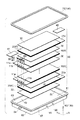
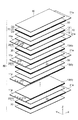
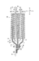
FIG. 1 is a cross-sectional view schematically showing an electrode group of a lithium ion secondary battery according to a first embodiment of the present invention. FIG. 2 is an exploded perspective view of the lithium ion secondary battery according to the first embodiment of the present invention. FIG. 3 is an exploded perspective view of an electrode group of the lithium ion secondary battery according to the first embodiment of the present invention. 4 to 17 are views for explaining a lithium ion secondary battery according to the first embodiment of the present invention. First, with reference to FIGS. 1-17, the lithium ion secondary battery by 1st Embodiment of this invention is demonstrated.
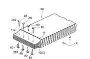
第1実施形態によるリチウムイオン二次電池は、図2および図5に示すように、角形扁平形状を有する大型二次電池であり、複数の電極5を含む電極群50(図1参照)と、この電極群50を非水電解液とともに封入する金属製の外装容器100とを備えている。
The lithium ion secondary battery according to the first embodiment is a large-sized secondary battery having a square flat shape as shown in FIGS. 2 and 5, and an electrode group 50 (see FIG. 1) including a plurality of
上記電極5は、図1〜図3に示すように、正極10および負極20を含んで構成されており、正極10と負極20との間には、正極10と負極20との短絡を抑制するためのセパレータ30が配されている。具体的には、正極10および負極20が、セパレータ30を挟んで互いに対向するように配されており、正極10、セパレータ30および負極20が順次積層されることによって、積層構造(積層体)に構成されている。なお、正極10および負極20は、1つずつ交互に積層されている。また、上記電極群50は、隣り合う2つの負極20の間に、1つの正極10が位置するように構成されている。
As shown in FIGS. 1 to 3, the
また、上記電極群50は、たとえば、正極10を13枚、負極20を14枚、セパレータ30を28枚含んで構成されており、正極10および負極20がセパレータ30を挟んで交互に積層されている。さらに、上記電極群50における最も外側(最外層の負極20の外側)には、セパレータ30が配されており、外装容器100との絶縁が図られている。
The
電極群50を構成する正極10は、図7に示すように、正極集電体11の両面に、正極活物質層12が担持された構成を有している。
As shown in FIG. 7, the
正極集電体11は、正極活物質層12の集電を行う機能を有している。
The positive electrode
ここで、第1実施形態では、上記正極集電体11は、絶縁性の樹脂層13の両面上に導電層14が形成された多層構造(三層構造)に構成されている。なお、樹脂層13は、本発明の「絶縁層」の一例である。
Here, in the first embodiment, the positive electrode
正極集電体11を構成する導電層14は、たとえば、アルミニウムまたはアルミニウム合金から構成されており、約6μm〜約15μmの厚みに形成されている。アルミニウムは耐酸化性が高いため、正極集電体11の導電層14として好適に用いることができる。なお、上記導電層14は、アルミニウムまたはアルミニウム合金以外であってもよく、たとえば、チタン、ステンレス鋼、ニッケルなどの金属材料、または、これらの合金などから構成されていてもよい。
The
導電層14の形成方法としては、特に限定されず、たとえば、蒸着、スパッタリング、電解めっき、無電解めっき、金属箔の貼り合わせ等による方法、および、これらの方法の組み合わせからなる方法が挙げられる。
The method for forming the
正極集電体11の樹脂層13は、熱可塑性樹脂からなるプラスチック材料から構成されている。この樹脂層13は、たとえば、シート状(フィルム状)の樹脂部材(樹脂フィルム)からなる。熱可塑性樹脂からなるプラスチック材料としては、たとえば、熱変形温度が150℃以下であるポリエチレン(PE)、ポリプロピレン(PP)等のポリオレフィン樹脂、ポリスチレン(PS)、ポリ塩化ビニル、ポリアミドなどが好適に用いられる。中でも、120℃での熱収縮率が平面方向のいずれかの方向(たとえば、縦方向および横方向のいずれかの方向)で1.5%以上であるポリエチレン(PE)、ポリプロピレン(PP)等のポリオレフィン樹脂、ポリ塩化ビニルなどが好ましい。また、これらの複合フィルムや、これらの表面加工処理を施した樹脂フィルムも好適に用いることができる。さらに、上記セパレータ30と同材質の樹脂フィルムを用いることも可能である。また、製造工程、加工処理の差異により、熱変形温度、熱収縮率等の異なる樹脂であれば、樹脂層13とセパレータ30とのいずれにも用いることができる。
The
また、樹脂層13の厚みは、特に限定されないが、二次電池としてのエネルギ密度向上と強度維持とのバランスを取るべく、5μm以上50μm以下であるのが好ましく、10μm以上20μm以下であればより好ましい。なお、樹脂層13(樹脂フィルム)は、一軸延伸、二軸延伸または無延伸などのいずれの方法で製造された樹脂フィルムでもかまわない。また、正極集電体11の樹脂層13は、フィルム状以外に、たとえば、繊維状であってもよい。
In addition, the thickness of the
なお、上記熱変形温度および熱収縮率とは、以下の方法で得られた値を意味する。また、熱変形温度は、樹脂層(樹脂フィルム)が熱収縮を開始する温度を意味する(熱変形温度および熱収縮率については、後述するセパレータについても同様である。)。 The heat distortion temperature and the heat shrinkage mean values obtained by the following method. The heat deformation temperature means a temperature at which the resin layer (resin film) starts to shrink (the same applies to the separator described later).
熱変形温度は、一定温度で一定時間、恒温槽で保持して、熱収縮率を測定し、収縮していない場合は温度を上げて、収縮している場合は温度を下げて、これを繰り返すことで測定する。具体的には、樹脂フィルムを、たとえば、100℃で15分間保持し、樹脂フィルムの熱収縮率を測定する。このときの熱収縮率が20%以下の場合、新しいサンプルを用いて温度を105℃に上げ、この温度で15分間保持した後、熱収縮率を測定する。この工程を、150℃に達するまで繰り返し、熱収縮率が10%以上となった時点の温度を熱変形温度とする。 The heat distortion temperature is kept at a constant temperature for a certain time in a thermostatic chamber, the heat shrinkage rate is measured, the temperature is increased if not contracted, the temperature is decreased if contracted, and this is repeated. To measure. Specifically, a resin film is hold | maintained for 15 minutes, for example at 100 degreeC, and the thermal contraction rate of a resin film is measured. When the heat shrinkage rate at this time is 20% or less, the temperature is raised to 105 ° C. using a new sample, and the temperature is kept at this temperature for 15 minutes, and then the heat shrinkage rate is measured. This process is repeated until the temperature reaches 150 ° C., and the temperature at which the heat shrinkage rate becomes 10% or more is defined as the heat distortion temperature.
また、熱収縮率の測定は、たとえば、樹脂フィルム上に50mm以上の間隔を空けて2つのポイントを付け、両者のポイント間距離を、ノギスを用いて測定する。その後、15分間、120℃(後述するセパレータについては180℃も)で加熱処理を行った後に、再度、同じポイント間距離を測定し、加熱処理前後の測定値に基づいて熱収縮率を求める。この方法に基づき、樹脂層(樹脂フィルム)の平面方向(たとえば、縦方向及び横方向)について、それぞれ3つ以上のポイント間距離を測定し、各々の測定結果から算出された熱収縮率の平均値を最終的な樹脂フィルムの熱収縮率として採用する。このとき、樹脂フィルムの縦方向及び横方向のそれぞれについて、少なくとも、樹脂フィルムの端部から10%以内の2点と、樹脂フィルムの端部から50%前後の1点を、ポイント間距離の測定地点として選定する。平面方向(たとえば、縦方向及び横方向)のいずれかの大きな値を熱収縮率とする。 Moreover, the measurement of a thermal contraction rate attaches two points on the resin film at intervals of 50 mm or more, for example, and measures the distance between both points using a caliper. Then, after heat-processing for 15 minutes at 120 degreeC (180 degreeC also about the separator mentioned later), the distance between the same points is measured again, and a thermal contraction rate is calculated | required based on the measured value before and behind heat processing. Based on this method, the distance between three or more points is measured for each of the plane directions (for example, the vertical direction and the horizontal direction) of the resin layer (resin film), and the average heat shrinkage rate calculated from each measurement result The value is adopted as the heat shrinkage rate of the final resin film. At this time, for each of the longitudinal direction and the lateral direction of the resin film, at least two points within 10% from the end of the resin film and one point around 50% from the end of the resin film are measured for the distance between the points. Select as a point. Any large value in the plane direction (for example, the vertical direction and the horizontal direction) is defined as the heat shrinkage rate.
正極活物質層12は、リチウムイオンを吸蔵・放出しうる正極活物質を含んで構成されている。正極活物質としては、たとえば、リチウムを含有した酸化物が挙げられる。具体的には、LiCoO2、LiFeO2、LiMnO2、LiMn2O4、および、これら酸化物中の遷移金属を一部他の金属元素で置換した化合物などが挙げられる。中でも、通常の使用において、正極が保有するリチウム量の80%以上を電池反応に利用し得るものを正極活物質に用いるのが好ましい。それにより過充電などの事故に対する二次電池の安全性を高めることが可能となる。このような正極活物質としては、たとえば、LiMn2O4のようなスピネル構造を有する化合物、および、LiMPO4(Mは、Co、Ni、Mn、Feから選択される少なくとも1種以上の元素)で表されるオリビン構造を有する化合物などが挙げられる。中でも、MnおよびFeの少なくとも一方を含む正極活物質がコストの観点から好ましい。さらに、安全性および充電電圧の観点からは、LiFePO4を用いるのが好ましい。LiFePO4は、全ての酸素(O)が強固な共有結合によって燐(P)と結合しているため、温度上昇による酸素の放出が起こりにくい。そのため、安全性に優れている。
The positive electrode
なお、上記正極活物質層12の厚みは、20μm〜2mm程度が好ましく、50μm〜1mm程度がより好ましい。
In addition, the thickness of the positive electrode
また、上記正極活物質層12は、正極活物質を少なくとも含んでいれば、その構成は特に制限されるものではない。たとえば、正極活物質層12は、正極活物質以外に、導電材、増粘材、結着材などの他の材料を含んでいてもよい。
Further, the configuration of the positive electrode
導電材は、正極10の電池性能に悪影響を及ぼさない電子伝導性材料であれば特に限定されず、たとえば、カーボンブラック、アセチレンブラック、ケッチェンブラック、グラファイト(天然黒鉛、人造黒鉛)、炭素繊維などの炭素質材料または導電性金属酸化物などを用いることができる。これらの中で、導電材としては、電子伝導性および塗工性の観点より、カーボンブラック及びアセチレンブラックが好ましい。
The conductive material is not particularly limited as long as it is an electron conductive material that does not adversely affect the battery performance of the
増粘材としては、たとえば、ポリエチレングリコール類、セルロース類、ポリアクリルアミド類、ポリN−ビニルアミド類、ポリN−ビニルピロリドン類などを用いることができる。これらの中で、増粘材としては、ポリエチレングリコール類、カルボキシメチルセルロース(CMC)などのセルロース類などが好ましく、CMCが特に好ましい。 As the thickener, for example, polyethylene glycols, celluloses, polyacrylamides, poly N-vinyl amides, poly N-vinyl pyrrolidones and the like can be used. Among these, as the thickener, celluloses such as polyethylene glycols and carboxymethyl cellulose (CMC) are preferable, and CMC is particularly preferable.
結着材は、活物質粒子および導電材粒子を繋ぎ止める役割を果たすものであり、たとえば、ポリフッ化ビニリデン(PVDF)、ポリビニルピリジン、ポリテトラフルオロエチレンなどのフッ素系ポリマー、ポリエチレン、ポリプロピレンなどのポリオレフィン系ポリマー、スチレンブタジエンゴムなどを用いることができる。 The binder serves to bind the active material particles and the conductive material particles, for example, a fluorine-based polymer such as polyvinylidene fluoride (PVDF), polyvinylpyridine, polytetrafluoroethylene, or a polyolefin such as polyethylene or polypropylene. A polymer, styrene butadiene rubber, or the like can be used.
正極活物質、導電材、結着材などを分散させる溶剤としては、たとえば、N−メチル−2−ピロリドン、ジメチルホルムアミド、ジメチルアセトアミド、メチルエチルケトン、シクロヘキサノン、酢酸メチル、アクリル酸メチル、ジエチルトリアミン、N,N−ジメチルアミノプロピルアミン、エチレンオキシド、テトラヒドロフランなどの有機溶剤を用いることができる。 Examples of the solvent for dispersing the positive electrode active material, the conductive material, the binder, and the like include, for example, N-methyl-2-pyrrolidone, dimethylformamide, dimethylacetamide, methyl ethyl ketone, cyclohexanone, methyl acetate, methyl acrylate, diethyltriamine, N, Organic solvents such as N-dimethylaminopropylamine, ethylene oxide, and tetrahydrofuran can be used.
上記した正極10は、たとえば、正極活物質、導電材、増粘材および結着材を混合し、適当な溶剤を加えてペースト状の正極合剤としたものを、正極集電体11の表面に塗布乾燥し、必要に応じて電極密度を高めるべく圧縮して形成される。
The
また、上記正極10は、図8に示すように、平面的に見て、略矩形形状を有している。正極10のY方向の幅W1は、たとえば、約100mmとされており、X方向の長さL1は、たとえば、約150mmとされている。また、正極活物質層12の塗布領域(形成領域)は、Y方向の幅W11が、正極10の幅W1と同じ、たとえば、約100mmとされており、X方向の長さL11が、たとえば、約135mmとされている。
Further, as shown in FIG. 8, the
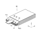
また、図7〜図9に示すように、上記正極10は、X方向の一端側に、正極活物質層12が形成されずに正極集電体11の表面(導電層14)が露出された集電体露出部(露出領域)11aを有している。この集電体露出部11aには、外部に電流を取り出すための、タブ電極41が電気的に接続されている。なお、タブ電極41は、たとえば、幅約30mm、長さ約70mmの形状に形成されている。
Moreover, as shown in FIGS. 7-9, the said
また、第1実施形態では、正極10の集電体露出部11aに、厚み方向に貫通する貫通孔11bが形成されている。この貫通孔11bは、複数の正極10を積層させた際に、各正極10の貫通孔11bが揃う(重なる)ように形成されている。なお、正極10の貫通孔11bには、後述する貫通部材80(図1参照)が挿通される。
Moreover, in 1st Embodiment, the through-
電極群50を構成する負極20は、図14に示すように、負極集電体21の両面に、負極活物質層22が担持された構成を有している。
The
負極集電体21は、負極活物質層22の集電を行う機能を有している。
The negative electrode
なお、第1実施形態では、負極集電体21は、上記正極集電体11(図7参照)とは異なり、樹脂層を含まない構成となっている。すなわち、正極集電体11(図7参照)のみが、樹脂層を含む多層構造に構成されている。
In the first embodiment, unlike the positive electrode current collector 11 (see FIG. 7), the negative electrode
具体的には、負極集電体21は、たとえば、銅、ニッケル、ステンレス鋼、鉄、ニッケルメッキ層などの金属箔、または、これらの合金からなる合金箔から構成されており、約1μm〜約100μm(たとえば約16μm)の厚みを有している。なお、負極集電体21は、リチウムと合金化しにくいという観点から、銅または銅合金からなる金属箔が好ましく、その厚みは、4μm以上20μm以下であるのが好ましい。
Specifically, the negative electrode
また、上記負極集電体21は、箔状以外に、フィルム状、シート状、ネット状、パンチ又はエキスパンドされたもの、ラス体、多孔質体、発泡体、繊維群の形成体などの形状であってもよい。
Moreover, the negative electrode
負極活物質層22は、リチウムイオンを吸蔵・放出しうる負極活物質を含んで構成されている。負極活物質としては、たとえば、リチウムを含む物質、あるいは、リチウムの吸蔵・放出が可能な物質からなる。また、高エネルギ密度電池を構成するためには、リチウムの吸蔵/放出する電位が金属リチウムの析出/溶解電位に近いものが好ましい。その典型例としては、粒子状(鱗片状、塊状、繊維状、ウィスカー状、球状、粉砕粒子状など)の天然黒鉛もしくは人造黒鉛が挙げられる。なお、負極活物質として、メソカーボンマイクロビーズ、メソフェーズピッチ粉末、等方性ピッチ粉末などを黒鉛化して得られる人造黒鉛を使用してもよい。また、非晶質炭素を表面付着させた黒鉛粒子を使用することもできる。さらに、リチウム遷移金属酸化物、リチウム遷移金属窒化物、遷移金属酸化物および酸化シリコンなども使用可能である。リチウム遷移金属酸化物としては、たとえば、Li4Ti5O12に代表されるチタン酸リチウムを使用すると、負極20の劣化が少なくなるため、電池の長寿命化を図ることが可能となる。
The negative electrode
なお、上記負極活物質層22の厚みは、20μm〜2mm程度が好ましく、50μm〜1mm程度がより好ましい。
The thickness of the negative electrode
また、上記負極活物質層22は、負極活物質を少なくとも含んでいれば、その構成は特に制限されるものではない。たとえば、負極活物質層22は、負極活物質以外に、導電材、増粘材、結着材などの他の材料を含んでいてもよい。なお、導電材、増粘材、結着材などの他の材料は、正極活物質層12と同じもの(正極活物質層12に用いることが可能なもの)を用いることができる。
Further, the configuration of the negative electrode
上記した負極20は、たとえば、負極活物質、導電材、増粘材および結着材を混合し、適当な溶剤を加えてペースト状の負極合剤としたものを、負極集電体21の表面に塗布乾燥し、必要に応じて電極密度を高めるべく圧縮して形成される。
The
また、上記負極20は、図15に示すように、平面的に見て、略矩形形状を有しており、正極10(図8および図9参照)と実質的に同じ大きさ(平面積)に形成されている。具体的には、第1実施形態では、上記負極20は、Y方向の幅W2が、正極10の幅W1(図8参照)と同じ、たとえば、約100mmとされており、X方向の長さL2が、正極10の長さL1(図8参照)と同じ、たとえば、約150mmとされている。また、負極活物質層22の塗布領域(形成領域)は、Y方向の幅W21が、負極20の幅W2と同じ、たとえば、約100mmとされており、X方向の長さL21が、たとえば、約135mmとされている。
Further, as shown in FIG. 15, the
また、図14〜図16に示すように、上記負極20は、正極10と同様、Y方向の一端に、負極活物質層22が形成されずに負極集電体21の表面が露出された集電体露出部21aを有している。この集電体露出部21aには、外部に電流を取り出すためのタブ電極42が電気的に接続されている。なお、タブ電極42は、上記タブ電極41と同様、たとえば、幅約30mm、長さ約70mmの形状に形成されている。
Further, as shown in FIGS. 14 to 16, the
電極群50を構成するセパレータ30(図1〜図3参照)は、たとえば、電気絶縁性の合成樹脂繊維、ガラス繊維、天然繊維等の不織布、織布または微多孔質膜などのなかから適宜選択可能である。中でも、ポリエチレン、ポリプロピレン、ポリエステル、アラミド系樹脂、セルロース系樹脂等の不織布、微多孔質膜が品質の安定性等の点から好ましく、特に、アラミド系樹脂、ポリエステルまたはセルロース系樹脂からなる不織布、微多孔質膜が好ましい。
The separator 30 (see FIGS. 1 to 3) constituting the
また、セパレータ30は、内部短絡によりリチウムイオン二次電池に発熱が生じた際に、セパレータ30の孔がふさがりイオン伝導を遮れるように、200℃以下に融点を持つことが好ましく、かつ、正極集電体11の樹脂層13よりも高い融点を有することが好ましい。たとえば、セパレータ30は、120℃での熱収縮率が正極集電体11の樹脂層13より小さくなるように構成されているのが好ましい。また、たとえば、セパレータ30は、正極集電体11の樹脂層13の熱変形温度以下の温度において、その熱収縮率が1.0%以下の材料から構成されているのが好ましい。さらに、セパレータ30は、180℃での熱収縮率が1.0%以下である、アラミド系樹脂、ポリエステル、セルロース系樹脂などの多孔質フィルムから構成されているのが好ましい。
Further, the
セパレータ30の厚みについては特に限定されるものではないが、必要量の電解液を保持することが可能であって、かつ、正極10と負極20との短絡を防ぐことが可能な厚みであるのが好ましい。具体的には、セパレータ30は、たとえば、0.02mm(20μm)〜0.1mm(100μm)の厚みとすることができる。なお、セパレータ30の厚みとしては、0.01mm〜1mm程度が好ましく、0.02mm〜0.05mm程度であればより好ましい。また、セパレータ30を構成する材質は、単位面積(1cm2)当たりの透気度が0.1秒/cm3〜500秒/cm3程度であると、低い電池内部抵抗を維持しつつ、電池内部短絡を防ぐだけの強度を確保できるため好ましい。
The thickness of the
なお、セパレータについても、熱変形温度および熱収縮率は、上述した樹脂層(樹脂フィルム)と同様の方法で得られた値を意味する。また、120℃での熱収縮率を測定する場合は、120℃で加熱処理を行い、180℃での熱収縮率を測定する場合は、180℃で加熱処理を行う。 In addition, also about a separator, a heat-deformation temperature and a heat-shrink rate mean the value obtained by the method similar to the resin layer (resin film) mentioned above. When measuring the heat shrinkage at 120 ° C., heat treatment is performed at 120 ° C., and when measuring the heat shrinkage at 180 ° C., heat treatment is performed at 180 ° C.
また、上記セパレータ30は、正極活物質層12の塗布領域(形成領域)および負極活物質層22の塗布領域(形成領域)よりも大きい形状を有している。具体的には、図17に示すように、上記セパレータ30は、矩形形状に形成されており、そのY方向の幅W3がたとえば約115mm、X方向の長さL3がたとえば約160mmに構成されている。
The
上記した正極10および負極20は、図1〜図3に示すように、正極10の集電体露出部11aと負極20の集電体露出部21aとが互いに反対側に位置するように配され、正極負極間にセパレータ30を介在させて積層されている。
As shown in FIGS. 1 to 3, the
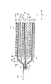
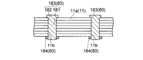
ここで、第1実施形態では、図1、図2および図4に示すように、積層された正極10の集電体露出部11aには、多層構造を有する正極集電体11を厚み方向に貫通する貫通部材80が設けられている。この貫通部材80は、導電性材料から構成されており、正極集電体11の貫通孔11bに挿通されることで、積層されている正極10(同極性の電極5)の全てを連続して貫通している。
Here, in the first embodiment, as shown in FIGS. 1, 2, and 4, the current collector exposed
また、上記貫通部材80は、たとえば、アイレット(ハトメ金具)と同様の形状を有しており、円筒状の胴体部81と、胴体部81の一端に設けられたやや直径の大きい頭部82とを含んで構成されている。そして、図6および図11に示すように、正極集電体11の貫通孔11bに貫通部材80を挿通した後、胴体部81の他端(頭部82とは反対側の端部)をかしめることで、積層された正極10が固定されている。
The penetrating
また、正極集電体11の貫通孔11bは、図13に示すように、その直径が、貫通部材80の胴体部81の直径と同程度に形成されている。そして、貫通部材80が貫通孔11bに挿通されることで、貫通部材80の胴体部81の表面(外表面)が、貫通孔11bの内側面と密接(電気的に接触)するように構成されている。これにより、正極集電体11における樹脂層13の一方側の導電層14と他方側の導電層14とが、貫通部材80を介して、互いに電気的に接続されているとともに、貫通部材80が全ての正極10を連続して貫通することで、積層された全ての正極10が互いに電気的に接続されている。
Further, as shown in FIG. 13, the through
さらに、貫通部材80は、上記のように、積層された電極(正極10)を束ねて固定するための締結部材としての機能をも有している。そして、この貫通部材80によって、積層された電極(正極10)が固定されることにより、各正極10の一部(集電体露出部11a)が、互いに密着された状態となっている。
Furthermore, the penetrating
なお、貫通部材80は、電気伝導性や耐酸化性などの観点から、アルミニウムまたはアルミニウム合金から構成されているのが好ましい。ただし、貫通部材80は、アルミニウムまたはアルミニウム合金以外であってもよく、たとえば、チタン、ステンレス鋼、ニッケルなどの金属材料、または、これらの合金などから構成されていてもよい。
The penetrating
また、図10〜図12に示すように、貫通部材80は、正極集電体11の集電体露出部11aの複数箇所に設けられているのが好ましい。このように、集電体露出部11aの複数箇所に貫通部材80を設ける(貫通させる)ことにより、正極同士の接触抵抗が低減するため、電極間(正極間)の導通が向上する。
As shown in FIGS. 10 to 12, the penetrating
電極群50の正極10においては、上記のように、貫通部材80で固定された状態で、最も外側の正極10(正極集電体11の導電層14)に上記したタブ電極41が溶接固定されている。なお、タブ電極41は、最外層ではなく、中間層の正極10に溶接固定されていてもよい。また、タブ電極41は、貫通部材80が設けられている領域に溶接固定されている。具体的には、図4、図10および図12に示すように、上記タブ電極41は、正極集電体11(正極10)の幅方向(Y方向)の略中央部(溶接領域M(図1参照))に、貫通部材80の頭部82を覆うようにして(貫通部材80と重なるよう配置にして)、溶接固定されている。これにより、積層された全ての正極10(全ての導電層14)が、タブ電極41と電気的に接続された状態となっている。この際、タブ電極41は、貫通部材80とも溶接されているのが好ましい。
In the
複数の負極20は、図1〜図3に示すように、正極10と同様、集電体露出部21aが揃うように積層されている。そして、最も外側の負極20(負極集電体21)に上記したタブ電極42が溶接固定されている。なお、正極の場合と同様、タブ電極42は、最外層ではなく、中間層の負極20に溶接固定されていてもよい。これにより、積層された全ての負極20が、タブ電極42に溶接固定され、タブ電極42と電気的に接続された状態となっている。なお、上記タブ電極42は、負極集電体21(負極20)の幅方向(Y方向)の略中央部に溶接固定されている。
As shown in FIGS. 1 to 3, the plurality of
タブ電極41および42の溶接は、超音波溶接が好ましいが、超音波溶接以外であってもよく、たとえば、レーザ溶接や抵抗溶接、スポット溶接などを用いてもよい。ただし、樹脂層13を挟んだ正極集電体11にタブ電極41を溶接する場合、レーザ溶接や抵抗溶接、スポット溶接などの熱を加えて接合する手法では、樹脂層13が溶解してしまうおそれがある。そのため、上記タブ電極41の溶接には、熱を加えない超音波溶接を用いるのが好ましい。
The welding of the
また、正極10に接続されるタブ電極41は、アルミニウムから構成されているのが好ましく、負極20に接続されるタブ電極42は、銅から構成されているのが好ましい。タブ電極41および42は、集電体と同材質のものを用いるのが好ましいが、異なる材質であってもよい。さらに、正極10に接続されるタブ電極41と負極20に接続されるタブ電極42とは、同材質であってもよいし、異なる材質であってもよい。また、タブ電極41および42は、上記のように、正極集電体11および負極集電体21の幅方向の略中央部に溶接されているのが好ましいが、中央部以外の領域に溶接固定されていてもよい。
The
外装容器100(図2参照)内に電極群50とともに封入される非水電解液は、特に限定されるものではないが、溶媒として、たとえば、エチレンカーボネート(EC)、プロピレンカーボネート、ブチレンカーボネート、ジエチルカーボネート(DEC)、ジメチルカーボネート、メチルエチルカーボネート、γ−ブチロラクトンなどのエステル類や、テトラヒドロフラン、2−メチルテトラヒドロフラン、ジオキサン、ジオキソラン、ジエチルエーテル、ジメトキシエタン、ジエトキシエタン、メトキシエトキシエタンなどのエーテル類、ジメチルスルホキシド、スルホラン、メチルスルホラン、アセトニトリル、ギ酸メチル、酢酸メチルなどの極性溶媒を使用することができる。これらの溶媒は単独で使用してもよいし、2種以上を混合して混合溶媒として使用してもよい。
The nonaqueous electrolytic solution enclosed with the
また、非水電解液には、電解質支持塩が含まれていてもよい。電解質支持塩としては、たとえば、LiClO4、LiBF4(ホウフッ化リチウム)、LiPF6(六フッ化リン酸リチウム)、LiCF3SO3(トリフルオロメタンスルホン酸リチウム)、LiF(フッ化リチウム)、LiCl(塩化リチウム)、LiBr(臭化リチウム)、LiI(ヨウ化リチウム)、LiAlCl4(四塩化アルミン酸リチウム)などのリチウム塩が挙げられる。これらは単独で使用してもよいし、2種以上を混合して使用してもよい。 The nonaqueous electrolytic solution may contain an electrolyte supporting salt. Examples of the electrolyte supporting salt include LiClO 4 , LiBF 4 (lithium borofluoride), LiPF 6 (lithium hexafluorophosphate), LiCF 3 SO 3 (lithium trifluoromethanesulfonate), LiF (lithium fluoride), L i Cl (lithium chloride), LiBr (lithium bromide), LiI (lithium iodide), LiAlCl 4 (tetrachloride lithium aluminate) include lithium salts such as. These may be used singly or in combination of two or more.
なお、電解質支持塩の濃度は、特に限定されるものではないが、0.5mol/L〜2.5mol/Lが好ましく、1.0mol/L〜2.2mol/Lがより好ましい。電解質支持塩の濃度が、0.5mol/L未満の場合には、非水電解液中において電荷を運ぶキャリア濃度が低くなり、非水電解液の抵抗が高くなるおそれがある。また、電解質支持塩の濃度が、2.5mol/Lより高い場合には、塩自体の解離度が低くなり、非水電解液中のキャリア濃度が上がらないおそれがある。 The concentration of the electrolyte supporting salt is not particularly limited, but is preferably 0.5 mol / L to 2.5 mol / L, and more preferably 1.0 mol / L to 2.2 mol / L. When the concentration of the electrolyte support salt is less than 0.5 mol / L, the carrier concentration for carrying charges in the non-aqueous electrolyte is lowered, and the resistance of the non-aqueous electrolyte may be increased. Further, when the concentration of the electrolyte supporting salt is higher than 2.5 mol / L, the dissociation degree of the salt itself is lowered, and there is a possibility that the carrier concentration in the non-aqueous electrolyte does not increase.
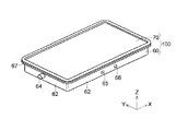
電極群50を封入する外装容器100は、図2および図5に示すように、大型の扁平角形容器であり、電極群50などを収納する外装缶60と、この外装缶60を封口する封口板70とを含んで構成されている。また、電極群50を収納した外装缶60には、たとえば、レーザ溶接によって、封口板70が取り付けられている。
As shown in FIGS. 2 and 5, the
外装缶60は、たとえば、金属板に深絞り加工などを施すことによって形成されており、底面部61と側壁部62とを有する略箱状に形成されている。また、図2に示すように、外装缶60の一端(底面部61の反対側)には、電極群50を挿入するための開口部63が設けられている。また、外装缶60は、電極群50が、その電極面が底面部61と対向するようにして収納することが可能な大きさに形成されている。
The outer can 60 is formed, for example, by deep drawing or the like on a metal plate, and is formed in a substantially box shape having a
また、図2および図5に示すように、上記外装缶60は、X方向の一方側(短辺側)の側壁部62に、電極端子64(たとえば、正極端子)が形成されており、X方向の他方側(短辺側)の側壁部62に、電極端子64(たとえば、負極端子)が形成されている。また、外装缶60の側壁部62には、非水電解液を注液するための注液孔65が形成されている。この注液孔65は、たとえば、φ2mmの大きさに形成されている。また、注液孔65の近傍には、電池内圧を開放するための安全弁66が形成されている。
As shown in FIGS. 2 and 5, the
さらに、外装缶60の開口部63の周縁には、折り返し部67が設けられており、この折り返し部67に、封口板70が溶接固定されている。
Further, a folded
外装缶60および封口板70は、たとえば、鉄、ステンレススチール、アルミニウムなどの金属板や鉄にニッケルメッキを施した鋼板などを用いて形成することができる。鉄は安価な材料であるため価格の観点では好ましいが、長期間の信頼性を確保するためには、ステンレススチール、アルミニウムなどからなる金属板または鉄にニッケルメッキを施した鋼板などを用いるのがより好ましい。金属板の厚みは、たとえば約0.4mm〜約1.2mm(たとえば約1.0mm)とすることができる。
The
また、上記した電極群50は、正極10および負極20が、外装缶60の底面部61と対向するようにして、外装缶60内に収納されている。収納された電極群50は、正極10の集電体露出部11aおよび負極20の集電体露出部21aが、それぞれ、タブ電極41および42を介して、外装缶60の電極端子64と電気的に接続されている。
The
また、非水電解液は、外装缶60の開口部63が封口板70で封口された後に、注液孔65から、たとえば、減圧注液されている。そして、注液孔65とほぼ同じ直径の金属球(図示せず)や、注液孔65より少し大きい金属板(図示せず)を注液孔65に設置した後、抵抗溶接やレーザ溶接などにより、注液孔65が封口されている。
In addition, the nonaqueous electrolytic solution is injected, for example, under reduced pressure from the
第1実施形態によるリチウムイオン二次電池では、上記のように、正極集電体11を厚み方向に貫通する貫通部材80を備えることによって、この貫通部材80を介して、正極集電体11における樹脂層13の一方側の導電層14と他方側の導電層14とを電気的に接続することができる。このため、この貫通部材80で、積層された複数の正極10(正極集電体11)の全てを連続して貫通することにより、多層構造を有する集電体(正極集電体11)を用いた場合でも、複数積層された電極同士の導通をとることができる。これにより、タブ電極41を、積層された複数の電極(正極10)の全てと電気的に接続することができる。したがって、電池性能の低下を抑制することができるので、リチウムイオン二次電池の性能を最大限活用することができる。
In the lithium ion secondary battery according to the first embodiment, as described above, by providing the penetrating
なお、第1実施形態では、上記貫通部材80を備えることによって、たとえば、超音波溶接でタブ電極41を電極(正極10)に接続する場合に、タブ電極41と電極(正極10)との接触抵抗、および、電極同士の接触抵抗を低減することができる。これにより、タブ電極41を電極(正極10)に強固に導通接続することが可能となる。なお、タブ電極41を電極(正極10)に強固に導通接続することにより、接触抵抗の増加に起因する電池容量の低下を抑制することもできる。
In the first embodiment, by providing the penetrating
また、第1実施形態では、上記のように、正極集電体11に多層構造を有する集電体を用いることによって、たとえば、過充電状態や高温状態等で異常発熱が発生した場合に、正極集電体11の樹脂層13が溶融して電極(正極10)が破損されるので、電流をカットすることができる。これにより、電池内部の温度上昇を抑制することができるので、発火などの異常状態が生じるのを防止することができる。
Further, in the first embodiment, as described above, by using a current collector having a multilayer structure as the positive electrode
また、第1実施形態では、締結部材として機能する貫通部材80で、複数積層された正極10(正極集電体11)を貫通することによって、正極集電体11の一部を互いに密着させることができるので、複数積層された正極10において、各正極10(各正極集電体11)の接触抵抗を低減して、タブ電極41と正極10、および、正極10同士をより強固に導通接続することができる。これにより、さらに効果的に、電池性能の低下を抑制することができる。
Moreover, in 1st Embodiment, the
なお、上記タブ電極41を貫通部材80が設けられている領域に溶接固定することにより、タブ電極41と正極10との導通を取りやすくすることができる。
The
また、第1実施形態では、正極集電体11に、貫通部材80が挿通される貫通孔11bを予め形成しておくことによって、容易に、貫通部材80を集電体の厚み方向に貫通させることができる。これにより、容易に、正極集電体11における樹脂層13の一方側の導電層14と他方側の導電層14とを電気的に接続することができる。
In the first embodiment, the through
また、第1実施形態では、正極集電体11の樹脂層13を、120℃での熱収縮率が、平面方向のいずれかの方向(たとえば、縦方向および横方向のいずれかの方向)で1.5%以上である熱可塑性樹脂から構成することによって、たとえば、過充電状態や高温状態等で異常発熱が発生した場合に、電極が破損され易くすることができる。これにより、効果的に、発火などの異常状態が生じるのを防止することができるので、リチウムイオン二次電池の安全性を効果的に向上させることができる。
In the first embodiment, the
また、正極集電体11の樹脂層13を、ポリオレフィン樹脂、ポリ塩化ビニル、または、これらの複合材料から構成すれば、容易に、リチウムイオン二次電池の安全性を向上させることができる。
Moreover, if the
また、第1実施形態では、セパレータ30を、120℃での熱収縮率が、正極集電体11の樹脂層13より小さくなるように構成することによって、セパレータ30のシャットダウン機能が作動する前に、正極10の集電体を構成する樹脂層13を溶断させることができる。これにより、樹脂層13およびセパレータ30による電流遮断効果により、2段階で電流遮断が可能となるので、リチウムイオン二次電池の安全性をより向上させることができる。
In the first embodiment, the
なお、上記セパレータ30の180℃での熱収縮率を、1.0%以下とすれば、過充電状態や高温状態等で異常発熱が発生した場合に、セパレータ30の熱収縮に起因する内部短絡(電極端部にて生じる電池の内部短絡)の発生を抑制することができるので、急激な温度上昇が生じるのを抑制することができる。このため、電池内部での発熱が生じた場合のセパレータ30の熱収縮に起因する内部短絡(電極端部にて生じる電池の内部短絡)の発生を抑制することができるので、急激な温度上昇が生じるのを抑制することができる。その結果、リチウムイオン二次電池の安全性をさらに向上させることができる。すなわち、このように構成すれば、180℃の温度でも、セパレータ30の溶融・流動化を抑制することができるので、溶融・流動化に起因してセパレータ30の孔が大きくなるという不都合が生じるのを抑制することができる。このため、電池内部が180℃に達した際に、何らかの理由で電極(正極10)の破損が起こらなかった場合でも、セパレータ30の孔が大きくなることに起因して、正負極の短絡箇所が広がるという不都合が生じるのを抑制することができる。
If the thermal contraction rate at 180 ° C. of the
実施例1では、正極活物質としてLiCoO2を100重量部、導電材としてアセチレンブラックを10重量部、バインダーとしてポリフッ化ビニリデン(PVDF)を10重量部、溶剤としてN−メチル−2−ピロリドン(NMP)をそれぞれ用い、正極活物質層を形成するためのペーストを作製した。また、15μmの厚みを有するプロピレンフィルム(樹脂層)の両面に、アルミニウム蒸着層(導電層)を1μmの厚みで形成することにより、正極集電体を作製した。そして、上記ペーストを正極集電体の両面に塗工し、十分に乾燥させた後、油圧プレスでプレスすることにより正極を得た。この正極における単位面積当たりの活物質の重量は、40mg/cm2であった。 In Example 1, 100 parts by weight of LiCoO 2 as a positive electrode active material, 10 parts by weight of acetylene black as a conductive material, 10 parts by weight of polyvinylidene fluoride (PVDF) as a binder, and N-methyl-2-pyrrolidone (NMP) as a solvent ) Were used to prepare pastes for forming the positive electrode active material layer. Moreover, the positive electrode current collector was produced by forming an aluminum vapor deposition layer (conductive layer) with a thickness of 1 μm on both sides of a propylene film (resin layer) having a thickness of 15 μm. And after apply | coating the said paste on both surfaces of a positive electrode electrical power collector and making it fully dry, the positive electrode was obtained by pressing with a hydraulic press. The weight of the active material per unit area in this positive electrode was 40 mg / cm 2 .
次に、負極活物質として中国産の天然黒鉛(平均粒径15μm、平均面間隔d002=0.3357nm、BET比表面積3m2/g)を100重量部、バインダーとしてPVDFを12重量部、溶剤としてNMPをそれぞれ用い、負極活物質層を形成するためのペーストを作製した。 Next, 100 parts by weight of Chinese natural graphite (average particle size 15 μm, average surface spacing d 002 = 0.3357 nm, BET specific surface area 3 m 2 / g) as negative electrode active material, 12 parts by weight of PVDF as binder, solvent NMP was used as a paste for forming a negative electrode active material layer.
ここで、実施例1では、負極集電体についても、正極集電体と同様、樹脂層の両面上に導電層が形成された多層構造に構成した。具体的には、15μmの厚みを有するプロピレンフィルム(樹脂層)の両面に、銅蒸着層(導電層)を1μmの厚みで形成することにより、負極集電体を作製した。そして、上記ペーストを負極集電体の両面に塗工し、十分に乾燥させた後、油圧プレスでプレスすることにより、負極を得た。 Here, in Example 1, the negative electrode current collector was also configured in a multilayer structure in which conductive layers were formed on both surfaces of the resin layer, similarly to the positive electrode current collector. Specifically, a negative electrode current collector was prepared by forming a copper vapor deposition layer (conductive layer) with a thickness of 1 μm on both sides of a propylene film (resin layer) having a thickness of 15 μm. And after apply | coating the said paste on both surfaces of a negative electrode collector, and making it fully dry, the negative electrode was obtained by pressing with a hydraulic press.
なお、実施例1では、セパレータとして、25μmの厚みを有するポリエチレン製の微多孔膜を用いた。また、正極集電体および負極集電体における活物質層が形成されていない領域(露出領域)には、貫通部材が挿通される貫通孔を形成した。 In Example 1, a polyethylene microporous film having a thickness of 25 μm was used as the separator. A through hole through which the penetrating member is inserted is formed in a region (exposed region) where the active material layer is not formed in the positive electrode current collector and the negative electrode current collector.
続いて、正極10を13枚、負極20を14枚、セパレータ30を28枚を用いて、正極10および負極20でセパレータ30を挟んで交互に積層することにより、電極群(積層体)を構成した。なお、電極群は、その最も外側(最外層の負極の外側)にセパレータが配された状態となっている。
Subsequently, 13
次に、正極および負極のそれぞれの貫通孔に、アイレット(ハトメ金具)と同様の形状を有する貫通部材を挿通させた後、貫通部材の端部をかしめることで、積層された各電極を固定した。なお、正極側の貫通部材には、アルミニウム製の貫通部材を用い、負極側の貫通部材には、銅製の貫通部材を用いた。 Next, after inserting a penetrating member having the same shape as an eyelet (eyelet fitting) into each through-hole of the positive electrode and the negative electrode, the stacked electrodes are fixed by caulking the end of the penetrating member. did. An aluminum penetrating member was used for the positive penetrating member, and a copper penetrating member was used for the negative penetrating member.
そして、貫通部材で固定された電極群の正極および負極の各々に、超音波溶接でタブ電極を固定した。なお、正極に固定したタブ電極は、アルミニウム製とし、負極に固定したタブ電極は、銅製とした。また、超音波溶接によって、各タブ電極を、貫通部材とも固定(電気的に接続)した。 And the tab electrode was fixed to each of the positive electrode of the electrode group fixed with the penetration member, and the negative electrode by ultrasonic welding. The tab electrode fixed to the positive electrode was made of aluminum, and the tab electrode fixed to the negative electrode was made of copper. Each tab electrode was also fixed (electrically connected) to the penetrating member by ultrasonic welding.
その後、上記電極群を外装容器内に封入し、非水電解液を注液することによって、実施例1によるリチウムイオン二次電池を作製した。 Then, the said electrode group was enclosed in the exterior container, the lithium ion secondary battery by Example 1 was produced by injecting a non-aqueous electrolyte.
得られたリチウムイオン二次電池を用いて充放電試験を行ったところ、多層構造を有する集電体を用いたにもかかわらず、電池性能の低下が認められなかった。これにより、リチウムイオン二次電池の性能を最大限活用することが可能であることが確認された。 When a charge / discharge test was performed using the obtained lithium ion secondary battery, no deterioration in battery performance was observed despite the use of a current collector having a multilayer structure. Thereby, it was confirmed that the performance of the lithium ion secondary battery can be utilized to the maximum extent.
(第1実施形態の第1変形例)
図18および図19は、第1実施形態の第1変形例によるリチウムイオン二次電池の電極群の一部を模式的に示した斜視図である。図20は、第1実施形態の第1変形例によるリチウムイオン二次電池の電極群の一部を模式的に示した断面図(貫通部材を含む断面に対応する図)である。
(First modification of the first embodiment)
18 and 19 are perspective views schematically showing a part of an electrode group of a lithium ion secondary battery according to a first modification of the first embodiment. FIG. 20 is a cross-sectional view (a view corresponding to a cross section including a penetrating member) schematically showing a part of an electrode group of a lithium ion secondary battery according to a first modification of the first embodiment.
第1実施形態の第1変形例では、図18〜図20に示すように、貫通部材80が略「コ」の字形状の針から構成されている。具体的には、この第1変形例では、上記貫通部材80が、たとえば、ステープラ針(ステープル)と同様の形状に構成されており、積層された正極集電体11(集電体露出部11a)を連続して貫通することで、複数の正極10が綴じられている。ステープラ針形状からなる貫通部材80は、たとえば、アルミニウムまたはアルミニウム合金などの導電性材料から構成されており、正極集電体11を貫通することで、正極集電体11における樹脂層13(図1、図6および図7参照)の一方側の導電層14(図1、図6および図7参照)と他方側の導電層14(図1、図6および図7参照)とを互いに電気的に接続している。
In the first modification of the first embodiment, as shown in FIGS. 18 to 20, the penetrating
また、正極集電体11には、タブ電極41が溶接固定されている。これにより、積層された全ての正極10(全ての導電層14(図1、図6および図7参照))が、タブ電極41と電気的に接続された状態となっている。
A
なお、ステープラ針形状からなる貫通部材80は、ステープラ等の機器を用いて正極集電体11を貫通させることが可能であるため、正極集電体11に予め貫通孔を設けておく必要がない。
Note that the penetrating
第1実施形態の第1変形例におけるその他の構成は、上記第1実施形態と同様である。また、第1実施形態の第1変形例の効果は、上記第1実施形態と同様である。 Other configurations in the first modification of the first embodiment are the same as those in the first embodiment. Moreover, the effect of the 1st modification of 1st Embodiment is the same as that of the said 1st Embodiment.
(第1実施形態の第2変形例)
図21および図22は、第1実施形態の第2変形例によるリチウムイオン二次電池の電極群の一部を模式的に示した斜視図である。図23は、第1実施形態の第2変形例によるリチウムイオン二次電池の電極群の一部を模式的に示した断面図(貫通部材を含む断面に対応する図)である。
(Second modification of the first embodiment)
21 and 22 are perspective views schematically showing a part of an electrode group of a lithium ion secondary battery according to a second modification of the first embodiment. FIG. 23 is a cross-sectional view (a diagram corresponding to a cross section including a penetrating member) schematically showing a part of an electrode group of a lithium ion secondary battery according to a second modification of the first embodiment.
第1実施形態の第2変形例では、図21〜図23に示すように、貫通部材80が2ピース構造に構成されている。具体的には、上記貫通部材80が、たとえば、本体部83と、この本体部83が挿入されるリング状の座金部84とを含んで構成されている。貫通部材80の本体部83は、上記第1実施形態と同様、円筒状の胴体部81と、この胴体部81の一端に設けられたやや直径の大きい頭部82とを有している。すなわち、この第2変形例の貫通部材80は、たとえば、両面ハトメ金具と同様の形状を有している。
In the second modification of the first embodiment, as shown in FIGS. 21 to 23, the penetrating
上記のように構成された第2変形例の貫通部材80は、その本体部83が、正極集電体11の貫通孔11bおよび座金部84に挿通された後、本体部83における胴体部81の他端(頭部82とは反対側の端部)がかしめられることで、積層された正極10を固定している。
The penetrating
第1実施形態の第2変形例におけるその他の構成は、上記第1実施形態と同様である。また、第1実施形態の第2変形例の効果は、上記第1実施形態と同様である。 Other configurations in the second modification of the first embodiment are the same as those in the first embodiment. The effect of the second modification of the first embodiment is the same as that of the first embodiment.
(第1実施形態の第3変形例)
図24および図25は、第1実施形態の第3変形例によるリチウムイオン二次電池の電極群の一部を模式的に示した斜視図である。図26は、第1実施形態の第3変形例によるリチウムイオン二次電池の電極群の一部を模式的に示した断面図(貫通部材を含む断面に対応する図)である。
(Third Modification of First Embodiment)
24 and 25 are perspective views schematically showing a part of an electrode group of a lithium ion secondary battery according to a third modification of the first embodiment. FIG. 26 is a cross-sectional view (a view corresponding to a cross section including a penetrating member) schematically showing a part of an electrode group of a lithium ion secondary battery according to a third modification of the first embodiment.
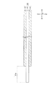
第1実施形態の第3変形例では、図24〜図26に示すように、貫通部材80がリベット状の導電性部材から構成されている。具体的には、上記貫通部材80が、たとえば、中実円柱状の胴体部181と、この胴体部181の一端に設けられたやや直径の大きい頭部182とを含んで構成されている。そして、図26に示すように、正極集電体11の貫通孔11bに貫通部材80(胴体部181)を挿通した後、胴体部181の他端(頭部182とは反対側の端部)をかしめることで、積層された正極10が固定されている。
In the third modification of the first embodiment, as shown in FIGS. 24 to 26, the penetrating
第1実施形態の第3変形例におけるその他の構成は、上記第1実施形態と同様である。また、第1実施形態の第3変形例の効果は、上記第1実施形態と同様である。 Other configurations in the third modified example of the first embodiment are the same as those in the first embodiment. The effect of the third modification of the first embodiment is the same as that of the first embodiment.
(第1実施形態の第4変形例)
図27および図28は、第1実施形態の第4変形例によるリチウムイオン二次電池の電極群の一部を模式的に示した斜視図である。図29は、第1実施形態の第4変形例によるリチウムイオン二次電池の電極群の一部を模式的に示した断面図(貫通部材を含む断面に対応する図)である。
(Fourth modification of the first embodiment)
27 and 28 are perspective views schematically showing a part of an electrode group of a lithium ion secondary battery according to a fourth modification of the first embodiment. FIG. 29 is a cross-sectional view (a view corresponding to a cross section including a penetrating member) schematically showing a part of an electrode group of a lithium ion secondary battery according to a fourth modification of the first embodiment.
第1実施形態の第4変形例では、図27〜図29に示すように、上記第3変形例と同様、貫通部材80がリベット状の導電性部材から構成されている。ただし、この第4実施形態では、貫通部材80が2ピース構造に構成されている。具体的には、上記貫通部材80が、本体部183と、この本体部183が挿通されて嵌合されるリング部材184とを含んで構成されている。本体部183は、中実円柱状の胴体部181と、この胴体部181の一端に設けられたやや直径の大きい頭部182とを有している。また、リング部材184の内径は、本体部183の胴体部181の直径よりやや小さく形成されている。そして、図29に示すように、正極集電体11の貫通孔11bに貫通部材80(胴体部181)を挿通した後、胴体部181の他端部(頭部182とは反対側の端部)にリング部材184を嵌め込むことで、本体部183とリング部材184とが嵌合され、積層された正極10が固定されている。
In the fourth modification of the first embodiment, as shown in FIGS. 27 to 29, the penetrating
第1実施形態の第4変形例におけるその他の構成は、上記第1実施形態と同様である。また、第1実施形態の第4変形例の効果は、上記第1実施形態と同様である。 Other configurations in the fourth modified example of the first embodiment are the same as those in the first embodiment. The effects of the fourth modification of the first embodiment are the same as those of the first embodiment.
(第1実施形態の第5変形例)
図30および図31は、第1実施形態の第5変形例によるリチウムイオン二次電池の電極群の一部を模式的に示した斜視図である。図32は、第1実施形態の第5変形例によるリチウムイオン二次電池の電極群の一部を模式的に示した断面図(貫通部材を含む断面に対応する図)である。
(Fifth Modification of First Embodiment)
30 and 31 are perspective views schematically showing a part of an electrode group of a lithium ion secondary battery according to a fifth modification of the first embodiment. FIG. 32 is a cross-sectional view (corresponding to a cross section including a penetrating member) schematically showing a part of an electrode group of a lithium ion secondary battery according to a fifth modification of the first embodiment.
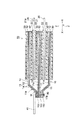
第1実施形態の第5変形例では、図30〜図32に示すように、貫通部材80が、針状(ピン状)の部材から構成されている。そのため、第5変形例の貫通部材80は、針状に尖った先端部を有している。また、第5変形例の貫通部材80は、針状に尖った先端部とは反対側の端部に、やや直径の大きい頭部282を有している。さらに、第5変形例の貫通部材80は、その全長が、積層された正極集電体11の厚みよりも大きくなるように構成されている。
In the fifth modification of the first embodiment, as shown in FIGS. 30 to 32, the penetrating
そして、正極集電体11の集電体露出部11aに、一方側から貫通部材80を貫通させた後、他方側から突出した部分に、たとえば、曲げ処理(曲げ加工)や押し潰し処理(押し潰し加工)などを施している。これにより、積層された正極10が固定されている。
And after letting the current collector exposed
なお、針状(ピン状)の部材からなる貫通部材80は、容易に、正極集電体11を貫通させることが可能であるため、上記第1変形例と同様、正極集電体11に予め貫通孔を設けておく必要がない。
Since the penetrating
第1実施形態の第5変形例におけるその他の構成は、上記第1実施形態と同様である。また、第1実施形態の第5変形例の効果は、上記第1実施形態と同様である。 Other configurations in the fifth modification of the first embodiment are the same as those in the first embodiment. The effects of the fifth modification of the first embodiment are the same as those of the first embodiment.
(第1実施形態の第6変形例)
図33および図34は、第1実施形態の第6変形例によるリチウムイオン二次電池の電極群の一部を模式的に示した斜視図である。図35は、第1実施形態の第6変形例によるリチウムイオン二次電池の電極群の一部を模式的に示した断面図(貫通部材を含む断面に対応する図)である。
(Sixth Modification of First Embodiment)
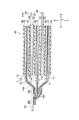
33 and 34 are perspective views schematically showing a part of an electrode group of a lithium ion secondary battery according to a sixth modification of the first embodiment. FIG. 35 is a cross-sectional view (corresponding to a cross section including a penetrating member) schematically showing a part of an electrode group of a lithium ion secondary battery according to a sixth modification of the first embodiment.
第1実施形態の第6変形例では、図33〜図35に示すように、貫通部材80が、第5変形例と同様、針状(ピン状)の部材から構成されている。ただし、この第6変形例では、上記第5変形例とは異なり、その全長が、積層された正極集電体11の厚みよりも小さくなるように構成されている。すなわち、この第6変形例では、複数積層された正極集電体11の全てを貫通するのではなく、複数積層された正極集電体11の一部を貫通するように構成されている。
In the sixth modification of the first embodiment, as shown in FIGS. 33 to 35, the penetrating
また、この第6変形例では、積層された正極集電体11の両側から、正極集電体11の集電体露出部11aに、それぞれ、針状(ピン状)の部材からなる貫通部材80が刺されている。また、図35に示すように、積層された正極集電体11の一部の集電体は、表側と裏側との両側から貫通部材80で貫通された状態となっている。これにより、針状(ピン状)の部材からなる貫通部材80によって、積層された正極10が固定されている。
Further, in this sixth modified example, penetrating
なお、第6変形例においても、上記第5変形例と同様、針状(ピン状)の部材からなる貫通部材80は、容易に、正極集電体11を貫通させることが可能であるため、正極集電体11に予め貫通孔を設けておく必要がない。
In the sixth modified example, as in the fifth modified example, since the penetrating
第1実施形態の第6変形例におけるその他の構成は、上記第1実施形態と同様である。また、第1実施形態の第6変形例の効果は、上記第1実施形態と同様である。 Other configurations in the sixth modification of the first embodiment are the same as those in the first embodiment. The effect of the sixth modification of the first embodiment is the same as that of the first embodiment.
(第2実施形態)
図36は、本発明の第2実施形態によるリチウムイオン二次電池の電極群を模式的に示した断面図である。図37は、図36の一部を拡大して示した断面図である。図38は、本発明の第2実施形態によるリチウムイオン二次電池の電極群の一部を模式的に示した平面図である。次に、図36〜図38を参照して、本発明の第2実施形態によるリチウムイオン二次電池について説明する。なお、各図において、対応する構成要素には同一の符号を付すことにより、重複する説明は適宜省略する。
(Second Embodiment)
FIG. 36 is a cross-sectional view schematically showing an electrode group of the lithium ion secondary battery according to the second embodiment of the present invention. FIG. 37 is an enlarged sectional view of a part of FIG. FIG. 38 is a plan view schematically showing a part of the electrode group of the lithium ion secondary battery according to the second embodiment of the present invention. Next, a lithium ion secondary battery according to a second embodiment of the present invention will be described with reference to FIGS. In addition, in each figure, the same code | symbol is attached | subjected to a corresponding component, and the overlapping description is abbreviate | omitted suitably.
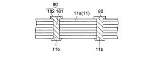
この第2実施形態では、図36および図37に示すように、上記第1実施形態の構成において、積層された正極集電体11の間に、導電性材料からなる金属箔(箔状部材)150が配された構成となっている。この金属箔150は、たとえば、アルミニウムまたはアルミニウム合金などから構成されている。また、図38に示すように、金属箔150は、たとえば、正極集電体11の集電体露出部11aに対応するように、略短冊状に形成されている。そして、正極集電体11の集電体露出部11a間に、それぞれ、上記金属箔150が配されている。
In the second embodiment, as shown in FIGS. 36 and 37, in the configuration of the first embodiment, a metal foil (foil-like member) made of a conductive material between the stacked positive electrode
また、第2実施形態では、図36〜図38に示すように、貫通部材80は、金属箔150が配された領域に設けられている。このため、上記金属箔150は、正極集電体11とともに、貫通部材80で貫通された状態となっている。
Moreover, in 2nd Embodiment, as shown in FIGS. 36-38, the
なお、上記金属箔150は、正極集電体11間のみならず、正極集電体11の外側にも配された構成とすることができる。また、上記金属箔150の厚みは、特に限定されないが、たとえば、約0.05mm〜約0.5mmにされていると好ましい。
The
第2実施形態のその他の構成は、上記第1実施形態と同様である。 Other configurations of the second embodiment are the same as those of the first embodiment.
第2実施形態では、上記のように、複数積層された正極10における正極集電体11(集電体露出部11a)の間に、導電性物質からなる金属箔150を配し、この金属箔150をも貫通するように、貫通部材80を集電体露出部11aに設けることによって、貫通部材80により、効果的に、正極10(正極集電体11)の導電層14を互いに電気的に接続することができる。加えて、効果的に、タブ電極41を、全ての正極10と電気的に接続することができる。これにより、電池性能の低下をより効果的に抑制することができる。したがって、上記のように構成すれば、容易に、安全性を向上させつつ、電池性能の低下を抑制することができる。
In the second embodiment, as described above, the
第2実施形態のその他の効果は、上記第1実施形態と同様である。 Other effects of the second embodiment are the same as those of the first embodiment.
なお、第2実施形態の貫通部材80については、上記第1実施形態で示した変形例(第1〜第6変形例)と同様の構成とすることができる。
In addition, about the
(第3実施形態)
図39は、本発明の第3実施形態によるリチウムイオン二次電池の電極群を模式的に示した断面図である。図40は、図39の一部を拡大して示した断面図である。図41〜図43は、本発明の第3実施形態によるリチウムイオン二次電池の電極群の一部を模式的に示した平面図である。次に、図39〜図43を参照して、本発明の第3実施形態によるリチウムイオン二次電池について説明する。なお、各図において、対応する構成要素には同一の符号を付すことにより、重複する説明は適宜省略する。
(Third embodiment)
FIG. 39 is a cross-sectional view schematically showing an electrode group of the lithium ion secondary battery according to the third embodiment of the present invention. FIG. 40 is an enlarged cross-sectional view of a part of FIG. FIGS. 41 to 43 are plan views schematically showing a part of the electrode group of the lithium ion secondary battery according to the third embodiment of the present invention. Next, with reference to FIGS. 39-43, the lithium ion secondary battery by 3rd Embodiment of this invention is demonstrated. In addition, in each figure, the same code | symbol is attached | subjected to a corresponding component, and the overlapping description is abbreviate | omitted suitably.
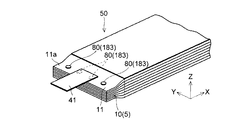
この第3実施形態では、上記第1および第2実施形態とは異なり、正極集電体11を貫通する貫通部材が設けられない構成となっている。また、第3実施形態では、図39および図40に示すように、積層された正極集電体11の間に、導電性材料からなる金属箔(箔状部材)160が配されている。この金属箔160は、たとえば、アルミニウムまたはアルミニウム合金などから構成されている。
In the third embodiment, unlike the first and second embodiments, a penetrating member that penetrates the positive electrode
また、第3実施形態では、上記第2実施形態とは異なり、金属箔160(金属箔160の一部)が正極集電体11の外側(活物質層12とは反対側)に延出(延在)するように配されている。具体的には、たとえば、図41に示すように、金属箔160が略短冊状に形成されているとともに、この金属箔160が、X方向にずらして配置されている。これにより、金属箔160が、正極集電体11の外側に延出(延在)している。
In the third embodiment, unlike the second embodiment, the metal foil 160 (a part of the metal foil 160) extends to the outside of the positive electrode current collector 11 (on the side opposite to the active material layer 12) ( Extended). Specifically, for example, as shown in FIG. 41, the
そして、図39および図40に示すように、正極集電体11の集電体露出部11aにタブ電極41が溶接固定されている。なお、タブ電極41は、金属箔160が配されている領域(溶接領域M1)に溶接固定されている。このため、正極集電体11とともに、金属箔160もタブ電極41に固定された状態となっている。また、第3実施形態では、金属箔160の延出部分が、溶接領域M2において、直接、タブ電極41に溶接固定されている。すなわち、この第3実施形態では、溶接領域M1と溶接領域M2との2箇所で、タブ電極41が溶接固定されている。これにより、積層された全ての正極10(全ての導電層14)が、金属箔160を介して、タブ電極41と電気的に接続された状態となっている。
As shown in FIGS. 39 and 40, the
なお、上記金属箔160は、正極集電体11間のみならず、正極集電体11の外側にも配された構成とすることができる。また、上記金属箔160の厚みは、特に限定されないが、たとえば、約0.05mm〜約0.5mmにされていると好ましい。
The
金属箔160の構成については、図41に示した構成以外に、たとえば、図42に示すように、タブ電極41に対応する部分が正極集電体11の外側に突出するように、略T字形状に構成してもよい。さらに、たとえば、図43に示すように、タブ電極41に対応するように、金属箔160を略矩形状に構成してもよい。
For the configuration of the
第3実施形態では、上記のように、複数積層された正極10における正極集電体11(集電体露出部11a)の間に、導電性物質からなる金属箔160を配し、その金属箔160の一部を、直接、タブ電極41に溶接することによって、各正極集電体11の導電層14を、金属箔160を介して、タブ電極41と電気的に接続することができる。このため、多層構造を有する集電体(正極集電体11)を用いた場合でも、全ての正極10を、タブ電極41と電気的に接続することができるので、電池性能の低下を抑制することができる。その結果、リチウムイオン二次電池の性能を最大限活用することができる。
In the third embodiment, as described above, the
第3実施形態のその他の効果は、上記第1実施形態と同様である。 Other effects of the third embodiment are the same as those of the first embodiment.
(第4実施形態)
図44は、本発明の第4実施形態によるリチウムイオン二次電池の電極群を模式的に示した断面図である。図45は、図44の一部を拡大して示した断面図である。次に、図44および図45を参照して、本発明の第4実施形態によるリチウムイオン二次電池について説明する。なお、各図において、対応する構成要素には同一の符号を付すことにより、重複する説明は適宜省略する。
(Fourth embodiment)
FIG. 44 is a cross-sectional view schematically showing an electrode group of the lithium ion secondary battery according to the fourth embodiment of the present invention. FIG. 45 is an enlarged cross-sectional view of a part of FIG. Next, with reference to FIGS. 44 and 45, a lithium ion secondary battery according to a fourth embodiment of the invention will be described. In addition, in each figure, the same code | symbol is attached | subjected to a corresponding component, and the overlapping description is abbreviate | omitted suitably.
第4実施形態によるリチウムイオン二次電池は、図44および図45に示すように、上記第3実施形態の構成に、さらに、貫通部材80が設けられた構成となっている。すなわち、第4実施形態によるリチウムイオン二次電池は、第1実施形態と第3実施形態とを組み合わせた構成となっている。
As shown in FIGS. 44 and 45, the lithium ion secondary battery according to the fourth embodiment has a configuration in which a penetrating
具体的には、積層された正極集電体11の間に、導電性材料からなる金属箔(箔状部材)160が配されており、金属箔160が配された領域(溶接領域M1)に、金属箔160をも貫通するように、貫通部材80が設けられている。また、各金属箔160は、その一部が、正極集電体11の外側(活物質層12とは反対側)に延出(延在)するように配されている。そして、第1実施形態で示したように、正極集電体11の集電体露出部11aにタブ電極41が溶接固定されている。また、上記第3実施形態で示したように、金属箔160の延出部分は、溶接領域M2において、直接、タブ電極41に溶接固定されている。
Specifically, a metal foil (foil-like member) 160 made of a conductive material is disposed between the stacked positive electrode
第4実施形態のその他の構成は、上記第1〜第3実施形態と同様である。 Other configurations of the fourth embodiment are the same as those of the first to third embodiments.
第4実施形態では、上記のように構成することによって、貫通部材80のみならず、金属箔160によっても、タブ電極41と各正極10とを電気的に接続することができる。このため、タブ電極41を正極10に、より強固に導通接続することができるので、より効果的に、タブ電極41を、全ての正極10と電気的に接続(接合)することができる。加えて、タブ電極41と正極10との接触抵抗をより低減することができる。
In the fourth embodiment, by configuring as described above, the
第4実施形態のその他の効果は、上記第1〜第3実施形態と同様である。 Other effects of the fourth embodiment are the same as those of the first to third embodiments.
また、第4実施形態の貫通部材80についても、上記第1実施形態で示した変形例(第1〜第6変形例)と同様の構成とすることができる。
Also, the penetrating
なお、今回開示された実施形態は、すべての点で例示であって制限的なものではないと考えられるべきである。本発明の範囲は、上記した実施形態の説明ではなく特許請求の範囲によって示され、さらに特許請求の範囲と均等の意味および範囲内でのすべての変更が含まれる。 The embodiment disclosed this time should be considered as illustrative in all points and not restrictive. The scope of the present invention is shown not by the above description of the embodiments but by the scope of claims for patent, and further includes all modifications within the meaning and scope equivalent to the scope of claims for patent.
たとえば、上記第1〜第4実施形態(変形例を含む)では、非水系二次電池の一例であるリチウムイオン二次電池に本発明を適用した例を示したが、本発明はこれに限らず、リチウムイオン二次電池以外の非水系二次電池に本発明を適用してもよい。また、今後開発される非水系二次電池に本発明を適用することもできる。 For example, in the first to fourth embodiments (including modifications), an example in which the present invention is applied to a lithium ion secondary battery that is an example of a non-aqueous secondary battery has been described, but the present invention is not limited thereto. First, the present invention may be applied to non-aqueous secondary batteries other than lithium ion secondary batteries. The present invention can also be applied to non-aqueous secondary batteries that will be developed in the future.
また、上記第1〜第4実施形態(変形例を含む)では、積層型の二次電池に本発明を適用した例を示したが、本発明はこれに限らず、積層型以外の、たとえば、巻回型の二次電池に本発明を適用してもよい。 In the first to fourth embodiments (including modifications), an example in which the present invention is applied to a stacked type secondary battery has been described. However, the present invention is not limited to this, and other than the stacked type, for example, The present invention may be applied to a wound type secondary battery.
また、上記第1〜第4実施形態(変形例を含む)では、集電体の樹脂層(絶縁層)にフィルム状の樹脂層を用いた例を示したが、本発明はこれに限らず、フィルム状以外に、たとえば、繊維状の樹脂層を用いてもよい。繊維状の樹脂層としては、たとえば、織布または不織布などからなる層が挙げられる。 Moreover, in the said 1st-4th embodiment (a modification is included), although the example which used the film-form resin layer for the resin layer (insulating layer) of the electrical power collector was shown, this invention is not limited to this. In addition to the film shape, for example, a fibrous resin layer may be used. As a fibrous resin layer, the layer which consists of a woven fabric or a nonwoven fabric etc. is mentioned, for example.
上記第1〜第4実施形態(変形例を含む)では、正極側の集電体を、樹脂層および導電層を含む多層構造に構成した例を示したが、本発明はこれに限らず、負極側の集電体を、樹脂層および導電層を含む多層構造に構成してもよい。たとえば、正極および負極の両方を、多層構造(三層構造)を有する集電体を用いて形成してもよいし、正極および負極の一方を、多層構造(三層構造)を有する集電体を用いて形成してもよい。なお、正極および負極の一方を、多層構造(三層構造)を有する集電体を用いて形成する場合、正極側を、多層構造(三層構造)を有する集電体を用いて形成するのが好ましい。 In the first to fourth embodiments (including modifications), the positive electrode current collector is shown in a multilayer structure including a resin layer and a conductive layer, but the present invention is not limited thereto, The current collector on the negative electrode side may have a multilayer structure including a resin layer and a conductive layer. For example, both the positive electrode and the negative electrode may be formed using a current collector having a multilayer structure (three-layer structure), or one of the positive electrode and the negative electrode has a multilayer structure (three-layer structure). You may form using. When one of the positive electrode and the negative electrode is formed using a current collector having a multilayer structure (three-layer structure), the positive electrode side is formed using a current collector having a multilayer structure (three-layer structure). Is preferred.
また、負極側の集電体を、多層構造に構成する場合、導電層は、銅または銅合金から構成されているのが好ましい。具体的には、導電層として、たとえば、約6μm〜約15μmの厚みを有する銅箔または銅合金箔を用いることができる。なお、負極集電体の導電層は、銅または銅合金以外であってもよく、たとえば、ニッケル、ステンレス鋼、鉄、または、これらの合金などから構成されていてもよい。また、負極集電体の樹脂層は、たとえば、正極集電体の樹脂層と同じもの(正極集電体11の樹脂層に用いることが可能なもの)を用いることができる。 Further, when the current collector on the negative electrode side has a multilayer structure, the conductive layer is preferably made of copper or a copper alloy. Specifically, for example, a copper foil or a copper alloy foil having a thickness of about 6 μm to about 15 μm can be used as the conductive layer. The conductive layer of the negative electrode current collector may be other than copper or a copper alloy, and may be composed of, for example, nickel, stainless steel, iron, or an alloy thereof. The resin layer of the negative electrode current collector can be, for example, the same as the resin layer of the positive electrode current collector (that can be used for the resin layer of the positive electrode current collector 11).
なお、負極側の集電体を多層構造に構成した場合、上記第1〜第4実施形態(変形例を含む)で示した正極(正極集電体)と同様、貫通部材または金属箔(箔状部材)を用いて、積層された複数の電極(負極)とタブ電極とが電気的に接続されるように構成される。この場合、貫通部材および金属箔は、銅または銅合金などから構成されているのが好ましい。 When the current collector on the negative electrode side has a multi-layer structure, the penetrating member or metal foil (foil) is the same as the positive electrode (positive electrode current collector) shown in the first to fourth embodiments (including modifications). The plurality of stacked electrodes (negative electrode) and the tab electrode are electrically connected using the shape member. In this case, it is preferable that the penetrating member and the metal foil are made of copper or a copper alloy.
また、上記第1、第2および第4実施形態では、積層した電極(集電体)の全てを貫通部材で貫通した構成を示したが、本発明はこれに限らず、積層した電極(集電体)の一部を貫通部材で貫通する構成にしてもよい。たとえば、積層した複数の電極(集電体)を複数の群(グループ)に分割し、群毎(グループ毎)に、電極(集電体)を貫通部材で貫通するようにしてもよい。すなわち、上記貫通部材は、2つ以上の電極(集電体)を連続して貫通するように構成されていればよい。 In the first, second, and fourth embodiments, the configuration in which all the stacked electrodes (current collectors) are penetrated by the penetrating member is shown. However, the present invention is not limited to this, and the stacked electrodes (collector) You may make it the structure which penetrates a part of electric body with a penetration member. For example, a plurality of stacked electrodes (current collectors) may be divided into a plurality of groups (groups), and the electrodes (current collectors) may be penetrated by penetrating members for each group (for each group). In other words, the penetrating member only needs to be configured to continuously penetrate two or more electrodes (current collectors).
また、上記第1、第2および第4実施形態では、タブ電極を、貫通部材が設けられている領域に溶接固定した例を示したが、本発明はこれに限らず、たとえば、図46に示すように、タブ電極41を、貫通部材80が設けられていない領域に溶接固定してもよい。
Moreover, in the said 1st, 2nd and 4th embodiment, although the example which weld-fixed the tab electrode to the area | region in which the penetration member was provided was shown, this invention is not limited to this, For example, FIG. As shown, the
また、上記第1、第2および第4実施形態において、集電体に設けられる貫通部材は、上記第1、第2および第4実施形態で示した構成以外の構成であってもよい。たとえば、図47に示すように、貫通部材80として、ボルト310およびナット320からなる締結部材300を用いてもよい。この際、必要に応じて、座金330などを介して締結部材300を締め込むようにしてもよい。また、たとえば、図48に示すように、貫通部材80として、頭部410と足部420とを有するビスネジ400(たとえば、片ネジ式ビス)を用いてもよい。
In the first, second and fourth embodiments, the penetrating member provided in the current collector may have a configuration other than the configurations shown in the first, second and fourth embodiments. For example, as shown in FIG. 47, a fastening member 300 including a
なお、上記実施形態において、集電体を貫通させる貫通部材の数(貫通箇所)は適宜変更することができる。貫通部材は、1箇所に設けられていてもよいし、複数箇所に設けられていてもよい。また、貫通部材は、金属材料から構成されているのが好ましいが、金属材料以外の導電性材料から構成されていてもよい。たとえば、上記貫通部材は、導電性プラスチック等の導電性樹脂などから構成されていてもよい。 In the above embodiment, the number of penetrating members that penetrate the current collector (penetrating locations) can be changed as appropriate. The penetrating member may be provided at one place or may be provided at a plurality of places. The penetrating member is preferably made of a metal material, but may be made of a conductive material other than the metal material. For example, the penetrating member may be made of a conductive resin such as a conductive plastic.
また、上記実施形態では、円柱状(円筒状)の胴体部を有する貫通部材を用いた例についても示したが、上記貫通部材の胴体部は、円柱状(円筒状)以外の形状であってもよい。たとえば、角柱状(角筒状)や楕円柱状(楕円筒状)などであってもよい。 Moreover, in the said embodiment, although it showed also about the example using the penetration member which has a column-shaped (cylindrical) trunk | drum, the trunk | drum of the said penetration member is shapes other than columnar (cylindrical), Also good. For example, a prismatic shape (rectangular cylindrical shape), an elliptical cylindrical shape (elliptical cylindrical shape), or the like may be used.
また、上記実施形態(第1実施形態の第5、第6変形例)では、針状に尖った先端部を有する貫通部材を用いた例を示したが、この貫通部材の先端部は、鋭角に尖った形状以外に、たとえば、ある程度丸みをおびた形状(丸まった形状)であってもよい。すなわち、「針状に尖った先端部」とは、電極(集電体)を貫通可能な形状であればよい。 Moreover, in the said embodiment (5th, 6th modification of 1st Embodiment), although the example using the penetration member which has a needle-like tip part was shown, the tip part of this penetration member has an acute angle. For example, the shape may be rounded to some extent (rounded shape). That is, the “needle-shaped tip” may be a shape that can penetrate the electrode (current collector).
なお、上記(実施形態等を含む)で示した以外の貫通部材を用いてもよい。 Note that penetrating members other than those described above (including the embodiment and the like) may be used.
また、上記第1、第2および第4実施形態(変形例を含む)では、貫通部材で電極を貫通させた後、タブ電極を電極に接続した例を示したが、本発明はこれに限らず、タブ電極をも含めて貫通部材で貫通させるようにしてもよい。 Moreover, in the said 1st, 2nd and 4th embodiment (a modification is included), after penetrating the electrode with the penetration member, the example which connected the tab electrode to the electrode was shown, but this invention is not limited to this Alternatively, the penetrating member may be penetrated including the tab electrode.
また、上記第1〜第4実施形態(変形例を含む)では、電極群を収容する外装容器に扁平角形容器を用いた例を示したが、本発明はこれに限らず、外装容器の形状は、扁平角形以外であってもよい。たとえば、上記外装容器は、薄い扁平筒型、円筒型、角筒型等であってもよい。ただし、大型のリチウムイオン二次電池の場合、組電池として使用することが多いため薄い扁平型または角型であるのが好ましい。さらに、上記外装容器は、金属製の缶以外に、たとえば、ラミネートシートなどを用いた外装容器であってもよい。 Moreover, in the said 1st-4th embodiment (a modification is included), although the example which used the flat rectangular container for the exterior container which accommodates an electrode group was shown, this invention is not limited to this, The shape of an exterior container May be other than a flat square. For example, the outer container may be a thin flat tube type, a cylindrical type, a rectangular tube type, or the like. However, in the case of a large-sized lithium ion secondary battery, since it is often used as an assembled battery, it is preferably a thin flat type or a square type. Further, the outer container may be an outer container using a laminated sheet, for example, in addition to a metal can.
また、上記第1〜第4実施形態(変形例を含む)では、正極(正極活物質層)と負極(負極活物質層)とが同じ大きさになるように構成した例を示したが、本発明はこれに限らず、正極および負極は互いに異なる大きさに構成されていてもよい。たとえば、正極(正極活物質層)よりも負極(負極活物質層)の方が大きくなるように構成されていてもよいし、負極(負極活物質層)よりも正極(正極活物質層)の方が大きくなるように構成されていてもよい。正極および負極が互いに異なる大きさに構成されている場合、正極(正極活物質層)よりも負極(負極活物質層)の方が大きくなるように構成されているのが好ましい。このように構成されていれば、正極活物質層の形成領域(正極活物質領域)が、面積の大きい負極活物質層の形成領域(負極活物質領域)で覆われることにより、積層ずれの許容範囲を広げることができる。 In the first to fourth embodiments (including modifications), the positive electrode (positive electrode active material layer) and the negative electrode (negative electrode active material layer) are configured to have the same size. The present invention is not limited to this, and the positive electrode and the negative electrode may have different sizes. For example, the negative electrode (negative electrode active material layer) may be configured to be larger than the positive electrode (positive electrode active material layer), or the positive electrode (positive electrode active material layer) may be configured to be larger than the negative electrode (negative electrode active material layer). It may be configured to be larger. When the positive electrode and the negative electrode are configured to have different sizes, the negative electrode (negative electrode active material layer) is preferably configured to be larger than the positive electrode (positive electrode active material layer). With this configuration, the positive electrode active material layer formation region (positive electrode active material region) is covered with a large area negative electrode active material layer formation region (negative electrode active material region), thereby allowing for stacking deviation. The range can be expanded.
なお、上記第1〜第4実施形態(変形例を含む)において、外装容器の大きさや形状等については種々変更することができる。また、電極(正極、負極)の形状、寸法、使用枚数なども、適宜変更することができる。さらに、セパレータの形状、寸法などについても、適宜変更することができる。セパレータの形状としては、たとえば、正方形または長方形等の矩形、多角形、円形等種々の形状が挙げられる。 In addition, in the said 1st-4th embodiment (a modification is included), about the magnitude | size, shape, etc. of an exterior container, it can change variously. Further, the shape, size, number of sheets used, etc. of the electrodes (positive electrode, negative electrode) can be changed as appropriate. Furthermore, the shape and dimensions of the separator can be changed as appropriate. Examples of the shape of the separator include various shapes such as a rectangle such as a square or a rectangle, a polygon, and a circle.
また、上記第1〜第4実施形態(変形例を含む)では、集電体の両面に活物質層を形成した例を示したが、本発明はこれに限らず、集電体の片面にのみ活物質層を形成してもよい。また、集電体の片面にのみ活物質層を形成した電極(正極、負極)を電極群の一部に含むように構成してもよい。 Moreover, in the said 1st-4th embodiment (a modification is included), although the example which formed the active material layer on both surfaces of the electrical power collector was shown, this invention is not restricted to this, On the single surface of an electrical power collector. Only the active material layer may be formed. Moreover, you may comprise so that the electrode (positive electrode, negative electrode) which formed the active material layer only in the single side | surface of a collector may be included in a part of electrode group.
また、上記第1〜第4実施形態(変形例を含む)では、リチウムイオン二次電池の電解質として非水電解液を用いた例を示したが、本発明はこれに限らず、非水電解液以外のたとえばゲル状電解質、高分子固体電解質、無機固体電解質、溶融塩などを電解質として用いてもよい。 Moreover, in the said 1st-4th embodiment (a modification is included), although the example which used nonaqueous electrolyte was shown as an electrolyte of a lithium ion secondary battery, this invention is not limited to this, Nonaqueous electrolysis For example, a gel electrolyte, a polymer solid electrolyte, an inorganic solid electrolyte, a molten salt, or the like other than the liquid may be used as the electrolyte.
なお、上記で開示された技術を適宜組み合わせて得られる実施形態についても本発明の技術的範囲に含まれる。 Note that embodiments obtained by appropriately combining the techniques disclosed above are also included in the technical scope of the present invention.
5 電極
10 正極
11 正極集電体
11a 集電体露出部
11b 貫通孔
12 正極活物質層
13 樹脂層(絶縁層)
14 導電層
20 負極
21 負極集電体
21a 集電体露出部
22 負極活物質層
30 セパレータ
41、42 タブ電極
50 電極群
60 外装缶
70 封口板
80 貫通部材
81、181 胴体部
82、182、282 頭部
100 外装容器
150、160 金属箔(箔状部材)
83、183 本体部
84 座金部
184 リング部材
DESCRIPTION OF
DESCRIPTION OF
83, 183
Claims (14)
導電性材料から構成され、前記集電体を厚み方向に貫通する貫通部材と、
前記電極と電気的に接続されるタブ電極とを備え、
前記電極は、前記活物質層が形成されずに前記導電層が露出された露出領域を有するとともに、複数積層されており、
前記貫通部材は、前記露出領域に設けられているとともに、2つ以上の前記電極を連続して貫通していることを特徴とする、非水系二次電池。 An electrode including a current collector having a multilayer structure in which a conductive layer is formed on both surfaces of an insulating layer; and an active material layer formed on the current collector;
A penetrating member made of a conductive material and penetrating the current collector in the thickness direction;
A tab electrode electrically connected to the electrode,
The electrode has an exposed region where the conductive layer is exposed without forming the active material layer , and a plurality of the electrodes are stacked,
The non-aqueous secondary battery, wherein the penetrating member is provided in the exposed region and continuously penetrates two or more of the electrodes.
前記正極および前記負極の少なくとも一方は、多層構造を有する前記集電体を用いて形成されていることを特徴とする、請求項1に記載の非水系二次電池。 The electrode includes a positive electrode and a negative electrode,
The nonaqueous secondary battery according to claim 1, wherein at least one of the positive electrode and the negative electrode is formed using the current collector having a multilayer structure.
前記貫通部材は、前記箔状部材をも貫通するように、前記電極の前記露出領域に設けられていることを特徴とする、請求項1〜3のいずれか1項に記載の非水系二次電池。 Between the exposed regions in the same polarity the electrode of the stacked multiple, foil-like member made of a conductive material are arranged,
The non-aqueous secondary according to claim 1, wherein the penetrating member is provided in the exposed region of the electrode so as to penetrate the foil-like member. battery.
前記集電体の前記導電層と電気的に接続されるタブ電極とを備え、
前記電極は、複数積層されており、
前記集電体は、前記活物質層が形成されずに前記導電層が露出された露出領域を有しているとともに、複数積層された同極性の前記電極における前記露出領域の間には、導電性物質からなる箔状部材が配されており、
前記タブ電極は、前記露出領域における前記箔状部材が配されている部分に溶接されているとともに、前記箔状部材の一部が、前記集電体の外側に延出されており、直接、前記タブ電極に溶接されていることを特徴とする、非水系二次電池。 An electrode including a current collector having a multilayer structure in which a conductive layer is formed on both surfaces of an insulating layer; and an active material layer formed on the current collector;
A tab electrode electrically connected to the conductive layer of the current collector,
A plurality of the electrodes are stacked,
The current collector has an exposed region in which the conductive layer is exposed without forming the active material layer, and a conductive layer is provided between the exposed regions of the stacked electrodes of the same polarity. A foil-like member made of a functional substance is arranged,
The tab electrode is welded to a portion of the exposed region where the foil-like member is disposed, and a part of the foil-like member extends to the outside of the current collector , A nonaqueous secondary battery, wherein the nonaqueous secondary battery is welded to the tab electrode.
前記セパレータは、120℃での熱収縮率が、前記集電体の絶縁層より小さいことを特徴とする、請求項1〜11のいずれか1項に記載の非水系二次電池。 The electrode includes a positive electrode and a negative electrode, and further includes a separator disposed between the positive electrode and the negative electrode,
The non-aqueous secondary battery according to claim 1, wherein the separator has a thermal shrinkage rate at 120 ° C. smaller than that of the insulating layer of the current collector.
Priority Applications (2)
| Application Number | Priority Date | Filing Date | Title |
|---|---|---|---|
| JP2010280843A JP5690575B2 (en) | 2010-12-16 | 2010-12-16 | Non-aqueous secondary battery |
| PCT/JP2011/077005 WO2012081368A1 (en) | 2010-12-16 | 2011-11-24 | Non-aqueous secondary battery |
Applications Claiming Priority (1)
| Application Number | Priority Date | Filing Date | Title |
|---|---|---|---|
| JP2010280843A JP5690575B2 (en) | 2010-12-16 | 2010-12-16 | Non-aqueous secondary battery |
Publications (3)
| Publication Number | Publication Date |
|---|---|
| JP2012129114A JP2012129114A (en) | 2012-07-05 |
| JP2012129114A5 JP2012129114A5 (en) | 2014-02-06 |
| JP5690575B2 true JP5690575B2 (en) | 2015-03-25 |
Family
ID=46244481
Family Applications (1)
| Application Number | Title | Priority Date | Filing Date |
|---|---|---|---|
| JP2010280843A Expired - Fee Related JP5690575B2 (en) | 2010-12-16 | 2010-12-16 | Non-aqueous secondary battery |
Country Status (2)
| Country | Link |
|---|---|
| JP (1) | JP5690575B2 (en) |
| WO (1) | WO2012081368A1 (en) |
Families Citing this family (36)
| Publication number | Priority date | Publication date | Assignee | Title |
|---|---|---|---|---|
| JP5693982B2 (en) * | 2011-01-25 | 2015-04-01 | シャープ株式会社 | Non-aqueous secondary battery |
| JP5574542B2 (en) * | 2011-10-11 | 2014-08-20 | アオイ電子株式会社 | Method for joining a plurality of electrode plate components |
| JP6250921B2 (en) * | 2012-09-14 | 2017-12-20 | 株式会社東芝 | battery |
| JP6639112B2 (en) * | 2015-06-05 | 2020-02-05 | アロイ工業株式会社 | Lead tab connection structure and connector for laminated battery |
| JP6737591B2 (en) * | 2015-12-14 | 2020-08-12 | アロイ工業株式会社 | Laminated battery electrode plate laminated fixing structure |
| CN108281662B (en) * | 2017-01-12 | 2020-05-05 | 宁德时代新能源科技股份有限公司 | Current collector, pole piece and battery thereof and application |
| US11539050B2 (en) | 2017-01-12 | 2022-12-27 | Contemporary Amperex Technology Co., Limited | Current collector, electrode plate and battery containing the same, and application thereof |
| EP3644426B1 (en) * | 2017-09-04 | 2021-11-03 | LG Chem, Ltd. | Method for manufacturing flexible battery, and flexible battery manufactured thereby |
| EP3467919A1 (en) * | 2017-10-09 | 2019-04-10 | Robert Bosch GmbH | Current collector with an improved security behavior and battery cell comprising the same |
| CN108428849B (en) * | 2017-11-22 | 2024-01-16 | 宁德时代新能源科技股份有限公司 | Electrode member, electrode assembly, and rechargeable battery |
| CN108428848B (en) * | 2017-11-22 | 2021-03-26 | 宁德时代新能源科技股份有限公司 | Electrode member, electrode assembly and rechargeable battery |
| CN109873163B (en) | 2017-12-05 | 2021-07-06 | 宁德时代新能源科技股份有限公司 | Current collector, pole piece and battery thereof and application |
| CN109873161B (en) * | 2017-12-05 | 2021-07-30 | 宁德时代新能源科技股份有限公司 | Battery with a battery cell |
| US10749184B2 (en) | 2017-12-05 | 2020-08-18 | Contemporary Amperex Technology Co., Limited | Battery |
| CN110048077B (en) * | 2018-01-16 | 2020-11-06 | 宁德时代新能源科技股份有限公司 | Electrode member, electrode assembly and rechargeable battery |
| CN110247055B (en) * | 2018-03-30 | 2020-12-04 | 宁德时代新能源科技股份有限公司 | Current collector, pole piece thereof and electrochemical device |
| DE102019105119A1 (en) * | 2019-02-28 | 2020-09-03 | Bayerische Motoren Werke Aktiengesellschaft | Metal-polymer current arrester for a battery cell of a motor vehicle |
| CN111755700A (en) * | 2019-03-29 | 2020-10-09 | 宁德新能源科技有限公司 | Composite current collector, electrode plate applying same and battery cell |
| CN111180664B (en) * | 2019-06-28 | 2022-03-15 | 宁德时代新能源科技股份有限公司 | Electrode plate and electrochemical device |
| KR20210061114A (en) * | 2019-11-19 | 2021-05-27 | 주식회사 엘지화학 | The Electrode Assembly And The Method For Thereof |
| WO2021125110A1 (en) * | 2019-12-19 | 2021-06-24 | ソフトバンク株式会社 | Manufacturing method, program, manufacturing system, stacked current collector, and battery |
| JP2021097020A (en) * | 2019-12-19 | 2021-06-24 | ソフトバンク株式会社 | Manufacturing method, program, manufacturing system, laminated current collector, and battery |
| JP7049308B2 (en) * | 2019-12-19 | 2022-04-06 | ソフトバンク株式会社 | Manufacturing methods, programs, and manufacturing systems |
| JP7049309B2 (en) * | 2019-12-19 | 2022-04-06 | ソフトバンク株式会社 | Manufacturing methods, programs, and manufacturing systems |
| CN114830383A (en) * | 2020-01-17 | 2022-07-29 | 富士胶片株式会社 | Nonaqueous electrolyte secondary battery, collector, and method for manufacturing nonaqueous electrolyte secondary battery |
| WO2021193407A1 (en) * | 2020-03-24 | 2021-09-30 | 日本碍子株式会社 | Zinc secondary battery |
| WO2021192289A1 (en) * | 2020-03-27 | 2021-09-30 | Tdk株式会社 | Current collector, power storage element, and power storage module |
| CN111509233A (en) * | 2020-05-29 | 2020-08-07 | 珠海冠宇电池股份有限公司 | Current collector and application thereof |
| JP2022131562A (en) * | 2021-02-26 | 2022-09-07 | ソフトバンク株式会社 | Battery structure, battery, manufacturing method, program, and manufacturing apparatus |
| CN112909443A (en) * | 2021-03-26 | 2021-06-04 | 厦门海辰新能源科技有限公司 | Tab assembly, preparation method thereof and battery cell |
| JP7343540B2 (en) * | 2021-04-21 | 2023-09-12 | プライムプラネットエナジー&ソリューションズ株式会社 | Secondary battery current collector and secondary battery |
| JP7123221B1 (en) * | 2021-06-18 | 2022-08-22 | ソフトバンク株式会社 | Manufacturing method, program, manufacturing system, laminated current collector, battery, moving object, and flying object |
| CN113571844A (en) * | 2021-07-14 | 2021-10-29 | 厦门海辰新能源科技有限公司 | Preparation method of current collector assembly, battery monomer and battery pack |
| WO2023065241A1 (en) * | 2021-10-21 | 2023-04-27 | 宁德时代新能源科技股份有限公司 | Battery cell and manufacturing method and manufacturing device therefor, battery, and electrical apparatus |
| WO2023216076A1 (en) * | 2022-05-09 | 2023-11-16 | 宁德时代新能源科技股份有限公司 | Pole piece, battery cell, battery and electrical apparatus |
| WO2024040503A1 (en) * | 2022-08-25 | 2024-02-29 | 宁德时代新能源科技股份有限公司 | Electrode assembly, preparation method, battery cell, battery, and electrical apparatus |
Family Cites Families (5)
| Publication number | Priority date | Publication date | Assignee | Title |
|---|---|---|---|---|
| JP5353032B2 (en) * | 2007-07-11 | 2013-11-27 | 日産自動車株式会社 | Stacked battery |
| JP4659861B2 (en) * | 2008-07-09 | 2011-03-30 | シャープ株式会社 | Flat secondary battery and manufacturing method thereof |
| JP4649502B2 (en) * | 2008-08-08 | 2011-03-09 | シャープ株式会社 | Lithium ion secondary battery |
| JP5124506B2 (en) * | 2009-02-13 | 2013-01-23 | シャープ株式会社 | Secondary battery and method for manufacturing secondary battery |
| JP2010262807A (en) * | 2009-05-01 | 2010-11-18 | Konica Minolta Holdings Inc | Secondary battery |
-
2010
- 2010-12-16 JP JP2010280843A patent/JP5690575B2/en not_active Expired - Fee Related
-
2011
- 2011-11-24 WO PCT/JP2011/077005 patent/WO2012081368A1/en active Application Filing
Also Published As
| Publication number | Publication date |
|---|---|
| JP2012129114A (en) | 2012-07-05 |
| WO2012081368A1 (en) | 2012-06-21 |
Similar Documents
| Publication | Publication Date | Title |
|---|---|---|
| JP5690575B2 (en) | Non-aqueous secondary battery | |
| JP5784928B2 (en) | Non-aqueous secondary battery | |
| JP5693982B2 (en) | Non-aqueous secondary battery | |
| US20130177787A1 (en) | Current collector and nonaqueous secondary battery | |
| JP2013008564A (en) | Nonaqueous secondary battery, and method of manufacturing the same | |
| JP2013012405A (en) | Nonaqueous secondary battery | |
| JP4927064B2 (en) | Secondary battery | |
| US20130022865A1 (en) | Current collector and nonaqueous secondary cell | |
| JP4649502B2 (en) | Lithium ion secondary battery | |
| JP5371979B2 (en) | Lithium ion secondary battery | |
| US20140170451A1 (en) | Electrode | |
| JP2012048913A (en) | Collector and electrode for nonaqueous secondary battery, and nonaqueous secondary battery | |
| JP2011029079A (en) | Nonaqueous electrolyte secondary battery | |
| JP2011159506A (en) | Nonaqueous secondary battery | |
| JP2010161249A (en) | Lithium ion capacitor | |
| JP5937969B2 (en) | Non-aqueous secondary battery | |
| WO2013002055A1 (en) | Current collector and electrode for use in non-aqueous secondary cell, and non-aqueous secondary cell | |
| JP6178183B2 (en) | Nonaqueous electrolyte battery, assembled battery and storage battery device | |
| JP2010282789A (en) | Nonaqueous electrolyte secondary battery | |
| JP2012074230A (en) | Collector and electrode for battery, and battery | |
| JP2016181457A (en) | Flat plate type laminate battery and battery pack thereof | |
| JP2002260603A (en) | Laminated outer package sealed battery | |
| JP4806053B2 (en) | Non-aqueous electrolyte secondary battery | |
| JP2011096504A (en) | Nonaqueous electrolyte secondary battery and manufacturing method of the same | |
| JP4710276B2 (en) | Secondary battery exterior member and secondary battery |
Legal Events
| Date | Code | Title | Description |
|---|---|---|---|
| A521 | Request for written amendment filed |
Free format text: JAPANESE INTERMEDIATE CODE: A523 Effective date: 20131212 |
|
| A621 | Written request for application examination |
Free format text: JAPANESE INTERMEDIATE CODE: A621 Effective date: 20131212 |
|
| A131 | Notification of reasons for refusal |
Free format text: JAPANESE INTERMEDIATE CODE: A131 Effective date: 20141111 |
|
| A521 | Request for written amendment filed |
Free format text: JAPANESE INTERMEDIATE CODE: A523 Effective date: 20141217 |
|
| RD03 | Notification of appointment of power of attorney |
Free format text: JAPANESE INTERMEDIATE CODE: A7423 Effective date: 20141217 |
|
| TRDD | Decision of grant or rejection written | ||
| A01 | Written decision to grant a patent or to grant a registration (utility model) |
Free format text: JAPANESE INTERMEDIATE CODE: A01 Effective date: 20150127 |
|
| A61 | First payment of annual fees (during grant procedure) |
Free format text: JAPANESE INTERMEDIATE CODE: A61 Effective date: 20150202 |
|
| R150 | Certificate of patent or registration of utility model |
Ref document number: 5690575 Country of ref document: JP Free format text: JAPANESE INTERMEDIATE CODE: R150 |
|
| LAPS | Cancellation because of no payment of annual fees |