WO2012117979A1 - 風車翼およびこれを備えた風力発電装置 - Google Patents
風車翼およびこれを備えた風力発電装置 Download PDFInfo
- Publication number
- WO2012117979A1 WO2012117979A1 PCT/JP2012/054664 JP2012054664W WO2012117979A1 WO 2012117979 A1 WO2012117979 A1 WO 2012117979A1 JP 2012054664 W JP2012054664 W JP 2012054664W WO 2012117979 A1 WO2012117979 A1 WO 2012117979A1
- Authority
- WO
- WIPO (PCT)
- Prior art keywords
- blade
- wind turbine
- maximum
- region
- thickness
- Prior art date
Links
- 230000005611 electricity Effects 0.000 title 1
- 230000007423 decrease Effects 0.000 abstract description 5
- 230000002093 peripheral effect Effects 0.000 description 15
- 238000004519 manufacturing process Methods 0.000 description 7
- 238000010248 power generation Methods 0.000 description 5
- 230000007717 exclusion Effects 0.000 description 4
- 238000004088 simulation Methods 0.000 description 4
- 230000007704 transition Effects 0.000 description 3
- 238000013459 approach Methods 0.000 description 2
- 230000000694 effects Effects 0.000 description 2
- 238000000034 method Methods 0.000 description 2
- 210000001015 abdomen Anatomy 0.000 description 1
- 238000006243 chemical reaction Methods 0.000 description 1
- 230000000052 comparative effect Effects 0.000 description 1
- 239000005431 greenhouse gas Substances 0.000 description 1
- 239000007787 solid Substances 0.000 description 1
- 238000011144 upstream manufacturing Methods 0.000 description 1
Images


Classifications
-
- F—MECHANICAL ENGINEERING; LIGHTING; HEATING; WEAPONS; BLASTING
- F03—MACHINES OR ENGINES FOR LIQUIDS; WIND, SPRING, OR WEIGHT MOTORS; PRODUCING MECHANICAL POWER OR A REACTIVE PROPULSIVE THRUST, NOT OTHERWISE PROVIDED FOR
- F03D—WIND MOTORS
- F03D1/00—Wind motors with rotation axis substantially parallel to the air flow entering the rotor
- F03D1/06—Rotors
- F03D1/0608—Rotors characterised by their aerodynamic shape
- F03D1/0633—Rotors characterised by their aerodynamic shape of the blades
- F03D1/0641—Rotors characterised by their aerodynamic shape of the blades of the section profile of the blades, i.e. aerofoil profile
-
- F—MECHANICAL ENGINEERING; LIGHTING; HEATING; WEAPONS; BLASTING
- F05—INDEXING SCHEMES RELATING TO ENGINES OR PUMPS IN VARIOUS SUBCLASSES OF CLASSES F01-F04
- F05B—INDEXING SCHEME RELATING TO WIND, SPRING, WEIGHT, INERTIA OR LIKE MOTORS, TO MACHINES OR ENGINES FOR LIQUIDS COVERED BY SUBCLASSES F03B, F03D AND F03G
- F05B2260/00—Function
- F05B2260/96—Preventing, counteracting or reducing vibration or noise
-
- Y—GENERAL TAGGING OF NEW TECHNOLOGICAL DEVELOPMENTS; GENERAL TAGGING OF CROSS-SECTIONAL TECHNOLOGIES SPANNING OVER SEVERAL SECTIONS OF THE IPC; TECHNICAL SUBJECTS COVERED BY FORMER USPC CROSS-REFERENCE ART COLLECTIONS [XRACs] AND DIGESTS
- Y02—TECHNOLOGIES OR APPLICATIONS FOR MITIGATION OR ADAPTATION AGAINST CLIMATE CHANGE
- Y02E—REDUCTION OF GREENHOUSE GAS [GHG] EMISSIONS, RELATED TO ENERGY GENERATION, TRANSMISSION OR DISTRIBUTION
- Y02E10/00—Energy generation through renewable energy sources
- Y02E10/70—Wind energy
- Y02E10/72—Wind turbines with rotation axis in wind direction
-
- Y—GENERAL TAGGING OF NEW TECHNOLOGICAL DEVELOPMENTS; GENERAL TAGGING OF CROSS-SECTIONAL TECHNOLOGIES SPANNING OVER SEVERAL SECTIONS OF THE IPC; TECHNICAL SUBJECTS COVERED BY FORMER USPC CROSS-REFERENCE ART COLLECTIONS [XRACs] AND DIGESTS
- Y10—TECHNICAL SUBJECTS COVERED BY FORMER USPC
- Y10S—TECHNICAL SUBJECTS COVERED BY FORMER USPC CROSS-REFERENCE ART COLLECTIONS [XRACs] AND DIGESTS
- Y10S416/00—Fluid reaction surfaces, i.e. impellers
- Y10S416/02—Formulas of curves
Definitions
- the present invention relates to a wind turbine blade and a wind turbine generator provided with the wind turbine blade.
- a wind turbine generator rotates wind turbine blades around an axis by wind power, and converts the rotational force into electric power to obtain a power generation output.
- the power generation output of the wind turbine generator is represented by the product of the shaft end output (output generated by the blade) and the conversion efficiency (efficiency of bearings, generators, etc.). Further, the shaft end output is expressed by the following formula, and if the blade has high blade efficiency and a large blade diameter, the power generation amount is improved.
- Shaft end output 1/2 x air density x wind speed ⁇ 3 x blade efficiency x ⁇ x (blade diameter / 2) ⁇ 2
- the upper limit value is about 0.5 due to the influence of the wind turbine wake and the air resistance of the blade. Therefore, further significant improvement in blade efficiency is difficult.
- the blade diameter has an influence on the output by its square, it is effective to increase the blade diameter to improve the power generation amount.
- the increase in blade diameter leads to an increase in aerodynamic load (thrust force acting in the inflow direction and moment transmitted to the blade root), which increases the size, weight, and cost of the rotor head, nacelle, tower, and other equipment.
- aerodynamic load thrust force acting in the inflow direction and moment transmitted to the blade root
- the increase in blade diameter leads to an increase in aerodynamic noise due to an increase in peripheral speed at the blade tip. Therefore, there is a need for an aerodynamic technique that achieves performance improvement and noise reduction without increasing the blade diameter.
- a wind turbine blade has a predetermined optimum cord length for a predetermined peripheral speed ratio, and has the following relationship (Wind Energy Handbook, John Wiley & Sons, p378).
- Copt is the optimum code length
- R (blade radius) is 1/2 of the blade diameter
- ⁇ is the design peripheral speed ratio
- CLdesign is the design lift coefficient
- r is the radial position of the blade cross section
- n is the number of blades.
- the design peripheral speed ratio is the tip peripheral speed / infinite upstream wind speed.
- the design lift coefficient is the lift coefficient at the angle of attack at which the lift / drag ratio (lift / drag) of the airfoil (blade cross section) is maximized.
- the (aerodynamic) shape and inflow conditions (Reynolds number) of the airfoil (blade cross section) It depends on.
- Patent Document 1 discloses an airfoil for improving wind turbine output. Specifically, an aerofoil having a blade thickness ratio in the range of 14% to 45% and a design lift coefficient in the range of 1.10 to 1.25 is disclosed (see claim 1).
- FIG. 14 shows the relationship of the above formula (1).
- the horizontal axis represents the dimensionless radius and the vertical axis represents the dimensionless code length.
- the dimensionless radius is a value (r / R) obtained by dividing the radial position r of the blade cross section from the rotation center by the blade radius R.
- the dimensionless code length is a value (c / R) obtained by dividing the code length c of the blade cross section by the blade radius R.
- the figure shows a plurality of curves in which the design lift coefficient CLdesign obtained from the above equation (1) is constant. Since the curve with the constant design lift coefficient CLdesign satisfies the above equation (1), the optimum code length (vertical axis) at the design peripheral speed ratio is given from the viewpoint of aerodynamic characteristics.
- the design peripheral speed ratio is 8.0 or more and 8.5 or less, and the Reynolds number is 3 million or more and 10 million or less.
- the optimum code length (dimensionalless) that optimizes the performance is given by the formula (1) when the radial position and the design peripheral speed ratio are determined” or “the radius position and the design code length can be determined.
- FIG. 15 shows an optimum code length distribution and an actual code length distribution (thick line) derived from the above equation (1).
- the actual code length is asymptotic to 0 (zero). Therefore, the difference between the optimum code length and the actual code length is inevitably large, and efficiency loss occurs. Therefore, there is a need for an aerodynamic design technique for improving aerodynamic performance and reducing aerodynamic noise in the blade tip region.
- the present invention has been made in view of such circumstances, and provides a wind turbine blade capable of improving aerodynamic performance in a blade tip region and reducing aerodynamic noise, and a wind turbine generator equipped with the wind turbine blade.
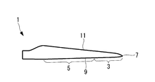
- a wind turbine blade according to a first aspect of the present invention includes a blade main body portion whose cord length decreases from the blade root side to the blade tip side, and the blade main body portion has a radial position at a blade radius (1/2 of the blade diameter). ), The blade tip region where the dimensionless radial position is 0.6 or more and 1.0 or less, and the blade body side region where the dimensionless radius position is less than 0.6, and the blade tip region The maximum blade thickness position in the blade cross section is positioned on the blade leading edge side with respect to the maximum blade thickness position in the blade cross section in the blade body side region.
- the present inventor examined the performance by variously changing the maximum blade thickness position in the blade section by numerical simulation. As a result, as the maximum blade thickness position is located closer to the blade leading edge, the aerodynamic performance is improved by increasing the design lift coefficient and the maximum lift-drag ratio, and the noise is reduced by reducing the boundary layer thickness (exclusion thickness). Was found to decrease. On the other hand, if the maximum blade thickness position is disposed forward, the blade trailing edge thickness is relatively thin, and the blade trailing edge strength is reduced with respect to the edge moment generated by the load applied to the wind turbine blade.
- the edge moment is smaller at the blade tip side than at the blade root side, and the maximum blade thickness position is arranged forward.
- the maximum blade thickness position in the blade tip region where the dimensionless radius position is 0.6 or more and 1.0 or less is greater than the maximum blade thickness position in the blade body side region where the dimensionless radius position is less than 0.6.
- the aerodynamic performance in the blade tip region can be improved, and aerodynamic noise in the blade tip region, which has the largest peripheral speed and is the main cause of noise, can be effectively reduced.
- the maximum blade thickness position may be displaced toward the blade leading edge side toward the blade tip in the blade tip region.
- the maximum blade thickness position is set to the blade tip even in the vicinity of the blade tip where the code length is reduced and the same blade cross section as the blade body side region cannot be maintained and the design lift coefficient has to be reduced.
- the dimensionless radial position in the tip region, is in the region of 0.6 or more and 0.9 or less, and the maximum blade thickness position is 25% code length or more and 40% code length or less. It is preferable that the maximum blade thickness position is 10% code length or more and 30% code length or less at a position where the dimensionless radius position is 1.0.
- the maximum blade thickness position in a region where the dimensionless radial position is 0.7 or more and 0.85 or less, is 26% code length or more and 36% code length or less. It is preferable that the maximum blade thickness position is 20% code length or more and 30% code length or less at the position where the dimension radius position is 1.0.
- the blade tip region is formed by connecting the maximum blade thickness position in the blade cross section of each radial position in the radial direction.
- the blade leading edge may be displaced toward the blade trailing edge such that the maximum blade thickness line is substantially linear.
- the maximum blade thickness line formed by connecting the maximum blade thickness positions in the blade cross section at each radial position in the radial direction is positioned so as to be substantially linear in the radial direction.
- the maximum blade thickness line is radiused by displacing the blade leading edge to the blade trailing edge side. It can be kept substantially straight in the direction.
- the blade leading edge shape of the wind turbine blade of the present invention for example, when the wind turbine blade is viewed in plan from the back side or the abdomen side, is largely displaced to the blade trailing edge side in the region where the blade main body side region transitions to the blade tip region, After that, a so-called S-shape is formed such that the blade is gradually displaced toward the blade trailing edge toward the blade leading edge, and finally displaced toward the blade trailing edge so as to be connected to the blade leading edge. Further, when the blade leading edge is displaced toward the blade trailing edge as in the present invention (particularly, when it is formed into an S shape), the blade trailing edge can be rounded to have a larger curvature. Thereby, the phase of the aerodynamic noise generated from the blade trailing edge in the blade tip region can be shifted in the blade radial direction, and noise can be further reduced.
- the wind turbine blade according to any one of the first aspects of the present invention may have a configuration in which the cross-sectional shape at the blade tip is a symmetric airfoil.
- the cross-sectional shape at the blade tip is a symmetric wing shape, that is, a wing shape with a camber of zero. This facilitates manufacture even on the blade tip side where it is difficult to manufacture a complicated shape with a thin blade thickness.
- the blade shape is such that the camber gradually approaches 0 toward the blade tip so that the camber is zero at the blade tip.
- a wind turbine generator includes a wind turbine blade described in any of the above, a rotor connected to a blade root side of the wind turbine blade, and rotated by the wind turbine blade, and the rotor. And a generator that converts the obtained rotational force into electrical output.
- wind turbine blades described above are provided, it is possible to provide a wind turbine generator with increased output due to improved aerodynamic performance and reduced aerodynamic noise.
- the aerodynamic performance of the blade tip region is improved and the blade Aerodynamic noise in the tip region can be effectively reduced.
- FIG. 13 shows an actual code length distribution.
- the wind turbine blade according to the first embodiment is preferably used as a blade of a wind power generator.
- three wind turbine blades are provided, and each is connected to the rotor with an interval of about 120 °.
- the rotating diameter (blade diameter) of the wind turbine blade is 60 m or more
- the solid blade (all blade projection area / blade sweep area) is an elongated blade having a blade diameter of 0.2 to 0.6.
- the wind turbine blades may have a variable pitch or a fixed pitch.
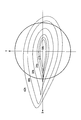
- the wind turbine blade 1 is a three-dimensional blade, and extends from the blade root side 1a, which is the rotation center side, toward the blade tip side 1b.
- the radial position (corresponding to the distance from the rotation center of the blade) of each blade thickness ratio (percentage of the maximum blade thickness divided by the cord length) Z (the longitudinal axis direction of the blade) at the position of the blade) represented by using a blade element section cut by a constant section.
- FIG. 1 shows that blade element cross sections cut at radial positions with blade thickness ratios of 18%, 21%, 24%, 30%, 36%, and 42% are used as the definition of the shape of the wind turbine blade. ing.
- a radial position r corresponding to the distance from the rotation center of the blade (or a dimensionless radial position r / R obtained by dividing the radial position by the blade radius). ) May be used.
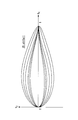
- FIG. 2 the blade element cross section of FIG. 1 is projected onto the XY plane (a plane perpendicular to the Z axis).
- the right side is the blade leading edge and the left side is the blade trailing edge.
- the wind turbine blade has a shape in which the cord length decreases from the blade root side to the blade tip side.
- the shape shown in the figure is called an airfoil.
- the dimensionless radial position r / R obtained by dividing the radial position r by the blade radius R (1/2 of the blade diameter) is 0.6 or more and 1.0 or less.
- the maximum blade thickness position in the blade cross section of the blade tip region 5 is located closer to the blade leading edge 9 than the maximum blade thickness position in the blade cross section of the blade body side region 7.
- each blade cross section shown in FIG. 5 when the cord length position of the blade leading edge is 0% cord length and the cord length position of the blade trailing edge is 100% cord length, the blade root side From the blade tip side to the blade tip side, the maximum blade thickness position is displaced (shifted) from the 40% cord length to the blade leading edge side, such as 36% cord length, 30% cord length, 24% cord length, 20% cord length, etc. is doing.
- line segment L1 has shown the largest blade
- the maximum blade thickness position in the blade main body side region 5 is 40% cord length or more. As shown in the figure, it is preferable that the maximum blade thickness position is gradually displaced toward the blade leading edge 9 toward the blade tip 7 (see FIG. 4).
- the maximum blade thickness position in the blade tip region 3 is a region where the dimensionless radius position is 0.6 or more and 0.9 or less, and is 25% code length or more and 40% code length or less, and the dimensionless radius position is 1 0 (ie, the position of the blade tip 7), the length is 10% or more and 30% or less. More preferably, the maximum blade thickness position in the blade tip region 3 is a region where the dimensionless radius position is 0.7 or more and 0.85 or less, and is 26% code length or more and 36% code length or less, and the dimensionless radius position is At a position set to 1.0, the code length is 20% code length or more and 30% code length or less.
- the airfoil has 0 camber. This facilitates manufacture even on the blade tip side where it is difficult to manufacture a complicated shape with a thin blade thickness.
- the camber gradually approaches 0 toward the blade tip 7 so that the camber becomes 0 at the blade tip 7.
- FIGS. 6 to 8 show the results of numerical simulation of the airfoil when the maximum blade thickness position is changed from 24% code length to 36% code length.
- the numerical simulation conditions were a design peripheral speed ratio of 8.0 to 8.5 and a Reynolds number of 3 million to 10 million.
- the design lift coefficient and the maximum lift-drag ratio are obtained. It can be seen that the aerodynamic performance is improved by increasing the noise and the noise is reduced by reducing the boundary layer thickness (exclusion thickness).
- the design lift coefficient and the maximum lift-drag ratio increase as the maximum blade thickness position is closer to the blade leading edge 9 side. It was found that the aerodynamic performance was improved and the noise was reduced by reducing the boundary layer thickness (exclusion thickness).
- the maximum blade thickness position is arranged on the blade leading edge 9 side, the blade trailing edge 11 is relatively thin, and the strength of the blade trailing edge 11 against the edge moment generated by the load applied to the wind turbine blade 1 is increased. May decrease.
- the edge moment on the blade tip 7 side is smaller than that on the blade root side, and the strength near the blade trailing edge 11 is high even if the maximum blade thickness position is arranged on the blade leading edge 9 side. Focused on not becoming a big problem. Therefore, in the present embodiment, the maximum blade thickness position of the blade tip region 3 is positioned closer to the blade leading edge 9 than the maximum blade thickness position of the blade body side region 5. As a result, the aerodynamic performance of the blade tip region 3 can be improved, and aerodynamic noise in the blade tip region, which has the largest peripheral speed and is the main cause of noise, can be effectively reduced.
- the aerodynamic performance can be improved by increasing the design lift coefficient and the maximum lift / drag ratio.
- the aerodynamic noise can be effectively reduced toward the blade tip 7 side where the peripheral speed increases and the noise increases.
- the present embodiment is provided for a wind turbine generator including a rotor connected to the blade root side of the wind turbine blade and rotated by the wind turbine blade, and a generator that converts the rotational force obtained by the rotor into an electrical output.
- the maximum blade thickness line formed by connecting the maximum blade thickness position in the blade cross section at each radial position in the blade radial direction is the blade leading edge 9 of the blade tip region 3 compared to the first embodiment.
- the points to be optimized differ depending on the shape of the blade, and the other points, that is, the point where the maximum blade thickness position in the blade tip region is positioned closer to the blade leading edge side than the maximum blade thickness position in the blade body side region are the same. Accordingly, differences will be described below, and description of similar points will be omitted.
- FIG. 9 shows the maximum blade thickness position at each radial position of the wind turbine blade according to the present embodiment.
- a line segment L2 in the figure indicates the maximum blade thickness position.
- the maximum blade thickness position is arranged at the same angular position when viewed from the blade rotation center at each radial position. As shown in the figure, this is realized by displacing the blade leading edge 9 toward the blade trailing edge 11 toward the blade tip side.
- the maximum blade thickness line formed by connecting the maximum blade thickness positions in the blade cross section at each radial position in the radial direction is arranged so as to be substantially linear in the radial direction of the wind turbine blade.
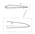
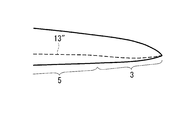
- FIG. 10 shows a maximum blade thickness line 13 that is substantially linear by displacing the blade leading edge 9 toward the blade trailing edge 11 as shown in FIG.
- the blade leading edge 9 in the blade tip region 3 is largely displaced toward the blade trailing edge 11 in the transition region 15 where the blade main body side region 5 transitions to the blade tip region 3 as shown in FIG.
- the blade is gradually displaced toward the blade leading edge 7 in the connection region 16 connected to the region 15, and finally connected to the blade tip 7 in the terminal region 17 connected to the connection region 16. It is a so-called S-shape that is displaced toward the trailing edge 11.
- the maximum blade thickness line 13 in a substantially straight line shape in the radial direction, the following effects are obtained.
- a girder that mainly bears the strength of the wind turbine blade extends in the radial direction.
- the maximum blade thickness line 13 ′ is formed linearly in the radial direction. It is because manufacture becomes easy by setting it as a linear girder.
- the maximum blade thickness position in the blade tip region is the same as that in the blade main body side region.
- the maximum blade thickness position of the blade tip region 3 when the maximum blade thickness position of the blade tip region 3 is positioned closer to the blade leading edge 9 than the maximum blade thickness position of the blade main body side region 5, FIG. If the same blade leading edge shape and blade trailing edge shape are to be adopted, the maximum blade thickness line 13 ′′ cannot maintain a linear shape in the blade tip region 3 as shown in FIG. End up.
- the maximum blade thickness line 13 is made substantially linear by displacing the blade leading edge 9 toward the blade trailing edge 11 (see FIG. 10).
- a substantially linear girder can be adopted, and the manufacture becomes easy.
- the receptor serving as the lightning strike point is disposed at the maximum blade thickness position, the receptor can be disposed in a substantially straight line, which facilitates manufacture.
- the blade leading edge 9 in the blade tip region 3 when the blade leading edge 9 in the blade tip region 3 is displaced toward the blade trailing edge 11 as in the present embodiment (particularly, the blade leading edge 9 has an S-shape).
- the wing trailing edge 11 can be rounded and have a larger curvature (see region 19 in the figure). Thereby, the phase of the aerodynamic noise generated from the blade trailing edge 11 in the blade tip region 3 can be shifted in the blade radial direction, and noise can be further reduced.
- the design peripheral speed ratio is set to 8.0 or more and 8.5 or less, but the present invention is not limited to this.
- the design peripheral speed ratio is 6.0 or more and 9.0 or less. Can also be applied.
Abstract
翼先端領域における空力性能を向上させるとともに空力騒音を低減することができる風車翼を提供する。翼根側から翼先端側にかけてコード長が減少する翼本体部を備え、翼本体部は、半径位置を翼半径(翼直径の1/2)で除した無次元半径位置が0.6以上1.0以下とされた翼先端領域と、無次元半径位置が0.6未満とされた翼本体側領域とを有し、翼先端領域の翼断面における最大翼厚位置(L1)が、翼本体側領域の翼断面における最大翼厚位置(L1)よりも翼前縁(9)側に位置されている。
Description
本発明は、風車翼およびこれを備えた風力発電装置に関する。
近年、発電時に温室効果ガスを排出しないクリーンエネルギーとして、風力発電装置が注目されている。風力発電装置は、風力によって風車翼を軸周りに回転させ、この回転力を電力に変換して発電出力を得る。
風力発電装置の発電出力は、軸端出力(翼が発生する出力)と、変換効率(軸受や発電機などの効率)との積で表される。また、軸端出力は次式で表され、翼効率が高く、翼直径が大きい翼であれば、発電量が向上する。
軸端出力=1/2×空気密度×風速^3×翼効率×π×(翼直径/2)^2
風力発電装置の発電出力は、軸端出力(翼が発生する出力)と、変換効率(軸受や発電機などの効率)との積で表される。また、軸端出力は次式で表され、翼効率が高く、翼直径が大きい翼であれば、発電量が向上する。
軸端出力=1/2×空気密度×風速^3×翼効率×π×(翼直径/2)^2
翼効率は、理論上の上限値(ベッツ限界=0.593)が存在し、実際上は風車後流の影響と翼の空気抵抗の存在で上限値は0.5程度となる。したがって、翼効率のこれ以上の大幅な改善は難しい。
一方、翼直径はその自乗で出力に影響を持つため、発電量向上のためには翼直径の拡大が効果的である。しかし、翼直径の拡大は、空力荷重(流入方向に作用するスラスト力および翼根に伝わるモーメント)の増大に繋がるため、ロータヘッド、ナセル、タワーなどの機器の大型化や重量増大、ひいてはコスト増に繋がる懸念・傾向がある。さらに、翼直径の拡大は、翼先端における周速の増大によって空力騒音の増加に繋がる。したがって、翼直径を拡大せずに、性能向上および騒音低下を実現する空力技術が求められる。
一方、翼直径はその自乗で出力に影響を持つため、発電量向上のためには翼直径の拡大が効果的である。しかし、翼直径の拡大は、空力荷重(流入方向に作用するスラスト力および翼根に伝わるモーメント)の増大に繋がるため、ロータヘッド、ナセル、タワーなどの機器の大型化や重量増大、ひいてはコスト増に繋がる懸念・傾向がある。さらに、翼直径の拡大は、翼先端における周速の増大によって空力騒音の増加に繋がる。したがって、翼直径を拡大せずに、性能向上および騒音低下を実現する空力技術が求められる。
一般に、風車翼は、所定の周速比に対して所定の最適コード長を持ち、次式の関係がある(Wind Energy Handbook, John Wiley & Sons, p378)。
Copt/R×λ2×CLdesign×r/R≒16/9×π/n ・・・(1)
ここで、Coptは最適コード長,R(翼半径)は翼直径の2分の1,λは設計周速比,CLdesignは設計揚力係数,rは翼断面の半径位置,nは翼枚数である。
設計周速比は、翼端周速/無限上流風速である。設計揚力係数は、翼型(翼断面)の揚抗比(揚力/抗力)が最大となる迎角における揚力係数であり、翼型(翼断面)の(空力)形状と流入条件(レイノルズ数)によって決まる。
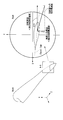
図13には、本明細書にて用いるレイノルズ数の定義が示されている。同図に示されているように、風車におけるレイノルズ数は、所定の回転数で回転する翼の所定断面A-Aにおける相対風速度を考慮したものであり、下式にて表される。
レイノルズ数=空気密度×翼断面への相対風速度×翼断面のコード長/空気の粘性係数
Copt/R×λ2×CLdesign×r/R≒16/9×π/n ・・・(1)
ここで、Coptは最適コード長,R(翼半径)は翼直径の2分の1,λは設計周速比,CLdesignは設計揚力係数,rは翼断面の半径位置,nは翼枚数である。
設計周速比は、翼端周速/無限上流風速である。設計揚力係数は、翼型(翼断面)の揚抗比(揚力/抗力)が最大となる迎角における揚力係数であり、翼型(翼断面)の(空力)形状と流入条件(レイノルズ数)によって決まる。
図13には、本明細書にて用いるレイノルズ数の定義が示されている。同図に示されているように、風車におけるレイノルズ数は、所定の回転数で回転する翼の所定断面A-Aにおける相対風速度を考慮したものであり、下式にて表される。
レイノルズ数=空気密度×翼断面への相対風速度×翼断面のコード長/空気の粘性係数
下記特許文献1には、風車出力向上のための翼型が開示されている。具体的には、翼厚比が14%から45%の範囲で設計揚力係数が1.10~1.25の範囲とされた翼型が開示されている(請求項1参照)。
図14には、上式(1)の関係が示されている。同図において、横軸は無次元半径、縦軸は無次元コード長を示す。無次元半径は、回転中心からの翼断面の半径位置rを翼半径Rで除した値(r/R)である。無次元コード長は、翼断面のコード長cを翼半径Rで除した値(c/R)である。
同図には、上式(1)から得られる設計揚力係数CLdesignが一定とされた曲線が複数示されている。設計揚力係数CLdesignが一定の曲線は、上式(1)を満たすので、空力特性の観点から、その設計周速比における最適コード長(縦軸)を与える。なお、同図では、設計周速比が8.0以上8.5以下、レイノルズ数が300万以上1000万以下とされている。
このように、「半径位置と設計周速比が定まれば性能最適となる最適コード長(無次元)が式(1)によって与えられる。」、または、「半径位置と設計コード長を定めれば、翼型(翼断面)の性能最適となる設計揚力係数が式(1)によって与えられる。」ということが導かれる。例えば、無次元半径r/R=0.6となる位置では、無次元コード長c/R=0.04が性能最適となる設計揚力係数は1.15である。
図15には、上式(1)によって導かれる最適なコード長分布と実際のコード長分布(太線)を示す。翼先端領域では、実際のコード長は0(ゼロ)に漸近するため、最適なコード長と実際のコード長の乖離が大きくならざるを得ず、効率損失が発生することになる。
そこで、翼先端領域において空力性能を向上させ、かつ、空力騒音を低減するための空力設計技術が求められる。
そこで、翼先端領域において空力性能を向上させ、かつ、空力騒音を低減するための空力設計技術が求められる。
本発明は、このような事情に鑑みてなされたものであって、翼先端領域における空力性能を向上させるとともに空力騒音を低減することができる風車翼およびこれを備えた風力発電装置を提供する。
上記課題を解決するために、本発明の風車翼およびこれを備えた風力発電装置は以下の手段を採用する。
本発明の第一の態様にかかる風車翼は、翼根側から翼先端側にかけてコード長が減少する翼本体部を備え、該翼本体部は、半径位置を翼半径(翼直径の1/2)で除した無次元半径位置が0.6以上1.0以下とされた翼先端領域と、無次元半径位置が0.6未満とされた翼本体側領域とを有し、該翼先端領域の翼断面における最大翼厚位置が、前記翼本体側領域の翼断面における最大翼厚位置よりも翼前縁側に位置されていることを特徴とする。
本発明の第一の態様にかかる風車翼は、翼根側から翼先端側にかけてコード長が減少する翼本体部を備え、該翼本体部は、半径位置を翼半径(翼直径の1/2)で除した無次元半径位置が0.6以上1.0以下とされた翼先端領域と、無次元半径位置が0.6未満とされた翼本体側領域とを有し、該翼先端領域の翼断面における最大翼厚位置が、前記翼本体側領域の翼断面における最大翼厚位置よりも翼前縁側に位置されていることを特徴とする。
本発明者は、数値シミュレーションにより、翼断面における最大翼厚位置を種々変化させて性能を検討した。その結果、最大翼厚位置が翼前縁側に位置するほど、設計揚力係数および最大揚抗比が増大することによって空力性能が向上し、境界層厚さ(排除厚さ)が減少することによって騒音が減少することが分かった。
一方、最大翼厚位置を前方に配置すると、相対的に翼後縁の厚さが薄くなり、風車翼に加わる荷重によって生じるエッジモーメントに対して、翼後縁強度が低下してしまう。
これに対して、本発明では、翼根側を中心として回転する風車翼の場合には、翼先端側では翼根側に比べてエッジモーメントが小さく、最大翼厚位置が前方に配置されていても翼後縁付近の強度は大きな問題にならないことに着目した。
そこで、無次元半径位置が0.6以上1.0以下とされた翼先端領域の最大翼厚位置を、無次元半径位置が0.6未満とされた翼本体側領域の最大翼厚位置よりも翼前縁側に位置することとした。これにより、翼先端領域の空力性能を向上させるとともに、最も周速が大きく騒音の主要因となる翼先端領域の空力騒音を効果的に低減することができる。
本発明の第一の態様に係る上記風車翼では、前記翼先端領域にて、最大翼厚位置が翼先端に向かって翼前縁側に変位されている構成であってもよい。
この構成によれば、コード長が小さくなり翼本体側領域と同一の翼断面を維持できずに設計揚力係数を低下させざるを得ない翼先端付近であっても、最大翼厚位置を翼先端側ほど翼前縁側に変位(シフト)させることによって、設計揚力係数および最大揚抗比を増大させて空力性能を向上させることができる。同時に、周速が大きくなり騒音が大きくなる翼先端側ほど効果的に空力騒音を低下させることができる。
本発明の第一の態様に係る上記風車翼において、先端領域では、無次元半径位置が0.6以上0.9以下の領域で、最大翼厚位置が25%コード長以上40%コード長以下とされ、無次元半径位置が1.0とされた位置で、最大翼厚位置が10%コード長以上30%コード長以下とされていることが好ましい。
本発明の第一の態様に係る上記風車翼において、無次元半径位置が0.7以上0.85以下の領域で、最大翼厚位置が26%コード長以上36%コード長以下とされ、無次元半径位置が1.0とされた位置で、最大翼厚位置が20%コード長以上30%コード長以下とされていることが好ましい。
本発明の第一の態様に係る上記いずれかの風車翼において、本発明の風車翼では、前記翼先端領域は、各半径位置の翼断面における最大翼厚位置を半径方向に接続して形成される最大翼厚線が略直線状となるように、翼前縁が翼後縁側に変位している構成であってもよい。
最大翼厚位置には、風車翼の強度を主として負担する桁が半径方向に延在して設けられる。したがって、各半径位置の翼断面における最大翼厚位置を半径方向に接続して形成される最大翼厚線は半径方向に略直線状となるように位置していることが好ましい。
本発明では、翼先端領域において翼本体側領域よりも最大翼厚位置を翼前縁側に位置させる場合であっても、翼前縁を翼後縁側に変位させることによって、最大翼厚線を半径方向に略直線状に維持することができる。
本発明の風車翼の翼前縁形状は、例えば、風車翼を背側または腹側から平面視した場合、翼本体部側領域から翼先端領域に遷移する領域で翼後縁側に大きく変位し、その後、翼先端側に向かって緩やかに翼後縁側に変位し、最終的に翼先端に接続されるように翼後縁側に変位するような、いわゆるS字形状となる。
また、本発明のように翼前縁を翼後縁側に変位させると(特にS字形状とすると)、翼後縁が丸みを帯びてより大きな曲率を有する形状とすることができる。これにより、翼先端領域の翼後縁から発生する空力騒音の位相を翼半径方向にずらすことができ、さらに騒音低減を図ることができる。
本発明の第一の態様に係る上記いずれかの風車翼では、翼先端における断面形状が対称翼型とされている構成であってもよい。
翼先端における断面形状を対称翼型とし、すなわちキャンバーが0とされた翼型とすることとした。これにより、翼厚が薄く複雑な形状の製造が困難な翼先端側であっても製造が容易となる。
好ましくは、翼先端領域の翼先端側では、翼先端でキャンバーが0になるように、翼先端に向かってキャンバーが0に漸近する翼型とされている。
好ましくは、翼先端領域の翼先端側では、翼先端でキャンバーが0になるように、翼先端に向かってキャンバーが0に漸近する翼型とされている。
本発明の第二の態様に係る風力発電装置は、上記のいずれかに記載された風車翼と、該風車翼の翼根側に接続され、該風車翼によって回転させられるロータと、該ロータによって得られた回転力を電気出力に変換する発電機とを備えていることを特徴とする。
上述した風車翼を備えているので、空力性能向上によって出力が増大し、空力騒音が低減された風力発電装置を提供することができる。
本発明によれば、翼先端領域の最大翼厚位置を、翼本体側領域の最大翼厚位置よりも翼前縁側に位置することとしたので、翼先端領域の空力性能を向上させるとともに、翼先端領域の空力騒音を効果的に低減することができる。
以下に、本発明の風車翼およびこれを備えた風力発電装置にかかる実施形態について、図面を参照して説明する。
[第1実施形態]
第1実施形態にかかる風車翼は、風力発電装置の翼として好適に用いられる。風車翼は、例えば3枚設けられ、それぞれが約120°の間隔を有してロータに接続されている。好ましくは、風車翼の回転直径(翼直径)は60m以上とされ、ソリディティ(全翼投影面積/翼掃過面積)が0.2以上0.6以下の細長翼とされる。風車翼は、可変ピッチとされていても良いし、固定ピッチとされていても良い。
[第1実施形態]
第1実施形態にかかる風車翼は、風力発電装置の翼として好適に用いられる。風車翼は、例えば3枚設けられ、それぞれが約120°の間隔を有してロータに接続されている。好ましくは、風車翼の回転直径(翼直径)は60m以上とされ、ソリディティ(全翼投影面積/翼掃過面積)が0.2以上0.6以下の細長翼とされる。風車翼は、可変ピッチとされていても良いし、固定ピッチとされていても良い。
図1に示すように、風車翼1は三次元翼とされており、回転中心側である翼根側1aから翼先端側1bに向かって延在している。
翼形状を定義する場合、同図に示されているように、各翼厚比(翼厚の最大値をコード長で除した値の百分率)の半径位置(翼の回転中心からの距離に相当する位置)においてZ(翼の長手軸方向)=一定の断面で切断した翼素断面を用いて表される。図1では、翼厚比が18%,21%,24%,30%,36%,42%の各半径位置にて切断した翼素断面が風車翼の形状の定義として用いられることが示されている。なお、風車翼1の半径位置を示す場合に、翼厚比に代えて、翼の回転中心からの距離に相当する半径位置r(あるいは半径位置を翼半径で除した無次元半径位置r/R)が用いられることもある。
翼形状を定義する場合、同図に示されているように、各翼厚比(翼厚の最大値をコード長で除した値の百分率)の半径位置(翼の回転中心からの距離に相当する位置)においてZ(翼の長手軸方向)=一定の断面で切断した翼素断面を用いて表される。図1では、翼厚比が18%,21%,24%,30%,36%,42%の各半径位置にて切断した翼素断面が風車翼の形状の定義として用いられることが示されている。なお、風車翼1の半径位置を示す場合に、翼厚比に代えて、翼の回転中心からの距離に相当する半径位置r(あるいは半径位置を翼半径で除した無次元半径位置r/R)が用いられることもある。
図2には、図1の翼素断面をXY平面(Z軸に直交する平面)へ投影したものである。同図のように風車翼1の長手方向先端から見た場合、右側が翼前縁、左側が翼後縁となる。同図に示されているように、風車翼は、翼根側から翼先端側にかけてコード長が減少する形状となっている。
図3は、風車翼1の各翼厚比における翼素断面に対して、その翼前縁をX=0,Y=0、翼後縁をX=1,Y=0で正規化したものである。同図のように表された形状を翼型という。
図3は、風車翼1の各翼厚比における翼素断面に対して、その翼前縁をX=0,Y=0、翼後縁をX=1,Y=0で正規化したものである。同図のように表された形状を翼型という。
図4に示すように、本実施形態の風車翼1は、半径位置rを翼半径R(翼直径の1/2)で除した無次元半径位置r/Rが0.6以上1.0以下とされた翼先端領域3と、無次元半径位置が0.6未満とされた翼本体側領域5とを有している。そして、翼先端領域5の翼断面における最大翼厚位置が、前記翼本体側領域7の翼断面における最大翼厚位置よりも翼前縁9側に位置されている。
具体的には、図5に示した各翼断面に示すように、翼前縁のコード長位置を0%コード長および翼後縁のコード長位置を100%コード長とした場合、翼根側から翼先端側に向かって、最大翼厚位置が例えば40%コード長から、36%コード長、30%コード長、24%コード長、20%コード長といったように翼前縁側に変位(シフト)している。なお、同図において線分L1が最大翼厚位置を示している。同図に示した風車翼の場合には、翼本体側領域5における最大翼厚位置は40%コード長以上とされる。
同図に示したように、最大翼厚位置が翼先端7(図4参照)に向かって翼前縁9側に漸次変位されていることが好ましい。
同図に示したように、最大翼厚位置が翼先端7(図4参照)に向かって翼前縁9側に漸次変位されていることが好ましい。
好ましくは、翼先端領域3における最大翼厚位置は、無次元半径位置が0.6以上0.9以下の領域で、25%コード長以上40%コード長以下とされ、無次元半径位置が1.0とされた位置(すなわち翼先端7の位置)で、10%コード長以上30%コード長以下とされている。
さらに好ましくは、翼先端領域3における最大翼厚位置は、無次元半径位置が0.7以上0.85以下の領域で、26%コード長以上36%コード長以下とされ、無次元半径位置が1.0とされた位置で、20%コード長以上30%コード長以下とされている。
さらに好ましくは、翼先端領域3における最大翼厚位置は、無次元半径位置が0.7以上0.85以下の領域で、26%コード長以上36%コード長以下とされ、無次元半径位置が1.0とされた位置で、20%コード長以上30%コード長以下とされている。
また、翼先端7では、対称翼型が採用されている。すなわちキャンバーが0とされた翼型とされている。これにより、翼厚が薄く複雑な形状の製造が困難な翼先端側であっても製造が容易となる。
好ましくは、翼先端領域3の翼先端7側では、翼先端7でキャンバーが0になるように、翼先端7に向かってキャンバーが0に漸近する翼型とされている。
好ましくは、翼先端領域3の翼先端7側では、翼先端7でキャンバーが0になるように、翼先端7に向かってキャンバーが0に漸近する翼型とされている。
次に、本実施形態のように、翼先端領域3の最大翼厚位置を、翼本体部側領域5の最大翼厚位置よりも翼前縁9側に位置させることとした理由について説明する。
図6乃至図8には、最大翼厚位置を24%コード長から36%コード長まで変化させた場合の翼型について数値シミュレーションを行った結果が示されている。数値シミュレーションの条件としては、設計周速比を8.0以上8.5以下、レイノルズ数を300万以上1000万以下とした。
これらの図から分かるように、翼先端領域3の最大翼厚位置を、翼本体部側領域5の最大翼厚位置よりも翼前縁9側に位置させると、設計揚力係数および最大揚抗比が増大することによって空力性能が向上し、境界層厚さ(排除厚さ)が減少することによって騒音が減少することが分かる。
図6乃至図8には、最大翼厚位置を24%コード長から36%コード長まで変化させた場合の翼型について数値シミュレーションを行った結果が示されている。数値シミュレーションの条件としては、設計周速比を8.0以上8.5以下、レイノルズ数を300万以上1000万以下とした。
これらの図から分かるように、翼先端領域3の最大翼厚位置を、翼本体部側領域5の最大翼厚位置よりも翼前縁9側に位置させると、設計揚力係数および最大揚抗比が増大することによって空力性能が向上し、境界層厚さ(排除厚さ)が減少することによって騒音が減少することが分かる。
以上の通り、本実施形態によれば以下の作用効果を奏する。
数値シミュレーションにより、翼断面における最大翼厚位置を種々変化させて性能を検討した結果、最大翼厚位置が翼前縁9側に位置するほど、設計揚力係数および最大揚抗比が増大することによって空力性能が向上し、境界層厚さ(排除厚さ)が減少することによって騒音が減少することが分かった。
一方、最大翼厚位置を翼前縁9側に配置すると、相対的に翼後縁11の厚さが薄くなり、風車翼1に加わる荷重によって生じるエッジモーメントに対して、翼後縁11の強度が低下してしまうおそれがある。
これに対して、本実施形態では、翼先端7側では翼根側に比べてエッジモーメントが小さく、最大翼厚位置が翼前縁9側に配置されていても翼後縁11付近の強度は大きな問題にならないことに着目した。
そこで、本実施形態では、翼先端領域3の最大翼厚位置を、翼本体側領域5の最大翼厚位置よりも翼前縁9側に位置することとした。これにより、翼先端領域3の空力性能を向上させるとともに、最も周速が大きく騒音の主要因となる翼先端領域の空力騒音を効果的に低減することができる。
また、コード長が小さくなり翼本体側領域5と同一の翼断面を維持できずに設計揚力係数を低下させざるを得ない翼先端7付近であっても、最大翼厚位置を翼先端7側ほど翼前縁9側に変位(シフト)させることによって、設計揚力係数および最大揚抗比を増大させて空力性能を向上させることができる。同時に、周速が大きくなり騒音が大きくなる翼先端7側ほど効果的に空力騒音を低下させることができる。
また、風車翼の翼根側に接続され、風車翼によって回転させられるロータと、ロータによって得られた回転力を電気出力に変換する発電機とを備えた風力発電装置に対して、本実施形態にかかる風車翼1を適用することにより、空力性能向上によって出力が増大し、空力騒音が低減された風力発電装置を実現することができる。
[第2実施形態]
次に、本発明の第2実施形態について説明する。本実施形態は、第1実施形態に対して、各半径位置の翼断面における最大翼厚位置を翼半径方向に接続して形成される最大翼厚線を、翼先端領域3の翼前縁9の形状によって適正化する点が異なり、その他の点、すなわち翼先端領域の最大翼厚位置を翼本体部側領域の最大翼厚位置よりも翼前縁側に位置させる点等については同様である。したがって、以下では相違点について説明し、同様の点については説明を省略する。
次に、本発明の第2実施形態について説明する。本実施形態は、第1実施形態に対して、各半径位置の翼断面における最大翼厚位置を翼半径方向に接続して形成される最大翼厚線を、翼先端領域3の翼前縁9の形状によって適正化する点が異なり、その他の点、すなわち翼先端領域の最大翼厚位置を翼本体部側領域の最大翼厚位置よりも翼前縁側に位置させる点等については同様である。したがって、以下では相違点について説明し、同様の点については説明を省略する。
図9には、本実施形態に係る風車翼の各半径位置における最大翼厚位置が示されている。同図における線分L2は、最大翼厚位置を示す。この最大翼厚位置は、各半径位置において、翼回転中心からみて同じ角度位置となるように配置されている。これは、同図に示されているように、翼先端側に行くにつれて翼前縁9を翼後縁11側に変位させることによって実現されている。これにより、各半径位置の翼断面における最大翼厚位置を半径方向に接続して形成される最大翼厚線が風車翼の半径方向に略直線状となるように配置されている。
図10には、図9のように翼前縁9を翼後縁11側に変位させることによって、略直線状となった最大翼厚線13が示されている。翼先端領域3における翼前縁9は、同図に示されているように、翼本体部側領域5から翼先端領域3に遷移する遷移領域15で翼後縁11側に大きく変位し、遷移領域15に接続された接続領域16で翼先端7側に向かって緩やかに翼後縁側に変位し、接続領域16に接続された終端領域17で最終的に翼先端7に接続されるように翼後縁11側に変位するような、いわゆるS字形状とされている。
図10には、図9のように翼前縁9を翼後縁11側に変位させることによって、略直線状となった最大翼厚線13が示されている。翼先端領域3における翼前縁9は、同図に示されているように、翼本体部側領域5から翼先端領域3に遷移する遷移領域15で翼後縁11側に大きく変位し、遷移領域15に接続された接続領域16で翼先端7側に向かって緩やかに翼後縁側に変位し、接続領域16に接続された終端領域17で最終的に翼先端7に接続されるように翼後縁11側に変位するような、いわゆるS字形状とされている。
このように、最大翼厚線13を半径方向に略直線状に延在させることによって、以下の作用効果を奏する。
一般に、最大翼厚位置には、風車翼の強度を主として負担する桁が半径方向に延在して設けられる。例えば、図11に示すように、従来の風車翼では、最大翼厚線13’は半径方向に直線状に形成されている。直線状の桁とすることによって、製造が容易となるからである。同図では、翼先端領域においても翼本体部側領域と同じ最大翼厚位置となっている。
しかし、第1実施形態で説明したように、翼先端領域3の最大翼厚位置を、翼本体部側領域5の最大翼厚位置よりも翼前縁9側に位置させた場合、図11と同様の翼前縁形状および翼後縁形状を採用しようとすると、図12に示すように、翼先端領域3において最大翼厚線13”が直線形状を維持することができず曲線状となってしまう。
そこで、本実施形態では、翼前縁9を翼後縁11側に変位させることによって最大翼厚線13を略直線状とすることとした(図10参照)。これにより、略直線状の桁を採用することができ、製造が容易となる。また、着雷点となるレセプタを最大翼厚位置に配置する場合にも、略直線状にレセプタを配置すればよいので、製造が容易となる。
また、図10に示されているように、本実施形態のように翼先端領域3における翼前縁9を翼後縁11側に変位させると(特に翼前縁9をS字形状とすると)、翼後縁11が丸みを帯びてより大きな曲率を有する形状とすることができる(同図の領域19参照)。これにより、翼先端領域3の翼後縁11から発生する空力騒音の位相を翼半径方向にずらすことができ、さらに騒音低減を図ることができる。
なお、本実施形態では、設計周速比を8.0以上8.5以下としたが、本発明はこれに限定されず、例えば設計周速比が6.0以上9.0以下であっても適用することができる。
1 風車翼
1a 翼根側
1b 翼先端側
3 翼先端領域
5 翼本体側領域
7 翼先端
9 翼前縁
11 翼後縁
13 最大翼厚線
1a 翼根側
1b 翼先端側
3 翼先端領域
5 翼本体側領域
7 翼先端
9 翼前縁
11 翼後縁
13 最大翼厚線
Claims (7)
- 翼根側から翼先端側にかけてコード長が減少する翼本体部を備え、
該翼本体部は、半径位置を翼半径(翼直径の1/2)で除した無次元半径位置が0.6以上1.0以下とされた翼先端領域と、無次元半径位置が0.6未満とされた翼本体側領域とを有し、
該翼先端領域の翼断面における最大翼厚位置が、前記翼本体側領域の翼断面における最大翼厚位置よりも翼前縁側に位置されていることを特徴とする風車翼。 - 前記翼先端領域にて、最大翼厚位置が翼先端に向かって翼前縁側に変位されていることを特徴とする請求項1に記載の風車翼。
- 翼前縁のコード長位置を0%コード長および翼後縁のコード長位置を100%コード長とした場合、
無次元半径位置が0.6以上0.9以下の領域で、最大翼厚位置が25%コード長以上40%コード長以下とされ、
無次元半径位置が1.0とされた位置で、最大翼厚位置が10%コード長以上30%コード長以下とされていることを特徴とする請求項2に記載の風車翼。 - 無次元半径位置が0.7以上0.85以下の領域で、最大翼厚位置が26%コード長以上36%コード長以下とされ、
無次元半径位置が1.0とされた位置で、最大翼厚位置が20%コード長以上30%コード長以下とされていることを特徴とする請求項3に記載の風車翼。 - 前記翼先端領域は、各半径位置の翼断面における最大翼厚位置を半径方向に接続して形成される最大翼厚線が略直線状となるように、翼前縁が翼後縁側に変位していることを特徴とする請求項1から4のいずれかに記載の風車翼。
- 翼先端における断面形状が対称翼型とされていることを特徴とする請求項1から5のいずれかに記載の風車翼。
- 請求項1から6のいずれかに記載された風車翼と、
該風車翼の翼根側に接続され、該風車翼によって回転させられるロータと、
該ロータによって得られた回転力を電気出力に変換する発電機と、
を備えていることを特徴とする風力発電装置。
Priority Applications (3)
| Application Number | Priority Date | Filing Date | Title |
|---|---|---|---|
| EP12752158.1A EP2682602B1 (en) | 2011-02-28 | 2012-02-24 | Wind turbine blade and wind-powered electricity generator provided with same |
| KR1020137022010A KR20130107370A (ko) | 2011-02-28 | 2012-02-24 | 풍차 날개 및 이것을 구비한 풍력 발전 장치 |
| US13/468,205 US8801387B2 (en) | 2011-02-28 | 2012-05-10 | Wind turbine blade and wind turbine generator including the same |
Applications Claiming Priority (2)
| Application Number | Priority Date | Filing Date | Title |
|---|---|---|---|
| JP2011043189A JP5479388B2 (ja) | 2011-02-28 | 2011-02-28 | 風車翼およびこれを備えた風力発電装置 |
| JP2011-043189 | 2011-02-28 |
Related Child Applications (1)
| Application Number | Title | Priority Date | Filing Date |
|---|---|---|---|
| US13/468,205 Continuation US8801387B2 (en) | 2011-02-28 | 2012-05-10 | Wind turbine blade and wind turbine generator including the same |
Publications (1)
| Publication Number | Publication Date |
|---|---|
| WO2012117979A1 true WO2012117979A1 (ja) | 2012-09-07 |
Family
ID=46757916
Family Applications (1)
| Application Number | Title | Priority Date | Filing Date |
|---|---|---|---|
| PCT/JP2012/054664 WO2012117979A1 (ja) | 2011-02-28 | 2012-02-24 | 風車翼およびこれを備えた風力発電装置 |
Country Status (5)
| Country | Link |
|---|---|
| US (1) | US8801387B2 (ja) |
| EP (1) | EP2682602B1 (ja) |
| JP (1) | JP5479388B2 (ja) |
| KR (1) | KR20130107370A (ja) |
| WO (1) | WO2012117979A1 (ja) |
Families Citing this family (14)
| Publication number | Priority date | Publication date | Assignee | Title |
|---|---|---|---|---|
| DK3835571T3 (da) * | 2010-07-16 | 2023-12-04 | Lm Wind Power As | Vindmøllevinge med smal skulder og relative tykke bæreplansprofiler |
| KR20130041263A (ko) * | 2010-10-22 | 2013-04-24 | 미츠비시 쥬고교 가부시키가이샤 | 풍차 날개 및 이를 구비한 풍력 발전 장치와 풍차 날개의 설계 방법 |
| GB201109412D0 (en) * | 2011-06-03 | 2011-07-20 | Blade Dynamics Ltd | A wind turbine rotor |
| DE102012206109C5 (de) * | 2012-04-13 | 2022-06-09 | Wobben Properties Gmbh | Rotorblatt einer Windenergieanlage |
| JP5995816B2 (ja) * | 2013-10-18 | 2016-09-21 | 三菱重工業株式会社 | 風車翼及び風力発電装置 |
| EP3130799A4 (en) * | 2014-03-28 | 2017-04-12 | The Chugoku Electric Power Co., Inc. | Wind turbine blade and wind power generator provided with same |
| DE102015012427A1 (de) * | 2015-09-25 | 2017-03-30 | Senvion Gmbh | Rotorblatt mit einem schalloptimierten Profil sowie Verfahren zum Herstellen eines Rotorblatts |
| WO2018041420A1 (en) * | 2016-08-30 | 2018-03-08 | Siemens Aktiengesellschaft | Flow control arrangement for a wind turbine rotor blade |
| JP6783212B2 (ja) * | 2017-10-20 | 2020-11-11 | 三菱重工業株式会社 | 風車翼へのボルテックスジェネレータの配置位置決定方法、風車翼アセンブリの製造方法及び風車翼アセンブリ |
| DE102017124861A1 (de) | 2017-10-24 | 2019-04-25 | Wobben Properties Gmbh | Rotorblatt einer Windenergieanlage und Verfahren zu dessen Auslegung |
| US11781522B2 (en) | 2018-09-17 | 2023-10-10 | General Electric Company | Wind turbine rotor blade assembly for reduced noise |
| DE102019119027B4 (de) * | 2019-07-12 | 2022-04-28 | Wobben Properties Gmbh | Rotorblatt und Windenergieanlage |
| US20230235721A1 (en) * | 2020-06-29 | 2023-07-27 | Vestas Wind Systems A/S | A wind turbine |
| JP2023554437A (ja) * | 2020-12-17 | 2023-12-27 | ヴェスタス ウィンド システムズ エー/エス | ブレード結合部材を有するピッチ制御風力タービン |
Citations (4)
| Publication number | Priority date | Publication date | Assignee | Title |
|---|---|---|---|---|
| US5474425A (en) * | 1992-03-18 | 1995-12-12 | Advanced Wind Turbines, Inc. | Wind turbine rotor blade |
| EP1152148A1 (en) | 2000-05-01 | 2001-11-07 | Enron Wind Energy Systems Co. | Airfoil profiles for wind turbines |
| JP2005533210A (ja) * | 2002-06-05 | 2005-11-04 | アロイス・ヴォベン | 風力発電装置のローターブレード |
| JP3935804B2 (ja) * | 2002-08-26 | 2007-06-27 | 三菱重工業株式会社 | 翼及びこれを備える風力発電装置 |
Family Cites Families (8)
| Publication number | Priority date | Publication date | Assignee | Title |
|---|---|---|---|---|
| US2709052A (en) * | 1952-04-15 | 1955-05-24 | Charles J Fletcher | Spanwise flow control of fluid swept lifting surfaces |
| US4976587A (en) * | 1988-07-20 | 1990-12-11 | Dwr Wind Technologies Inc. | Composite wind turbine rotor blade and method for making same |
| KR101033544B1 (ko) * | 2001-09-17 | 2011-05-11 | 클린 커런트 리미티드 파트너쉽 | 수중 덕트 터빈 |
| JP3368537B1 (ja) * | 2001-11-08 | 2003-01-20 | 学校法人東海大学 | 直線翼型風水車 |
| DE10319246A1 (de) * | 2003-04-28 | 2004-12-16 | Aloys Wobben | Rotorblatt einer Windenergieanlage |
| US8142162B2 (en) | 2005-07-15 | 2012-03-27 | Vestas Wind Systems A/S | Wind turbine blade |
| US7789629B2 (en) * | 2006-12-07 | 2010-09-07 | Verdant Power | Non-fouling kinetic hydro power system axial-flow blade tip treatment |
| DE102008052858B9 (de) * | 2008-10-23 | 2014-06-12 | Senvion Se | Profil eines Rotorblatts und Rotorblatt einer Windenergieanlage |
-
2011
- 2011-02-28 JP JP2011043189A patent/JP5479388B2/ja active Active
-
2012
- 2012-02-24 KR KR1020137022010A patent/KR20130107370A/ko not_active Application Discontinuation
- 2012-02-24 WO PCT/JP2012/054664 patent/WO2012117979A1/ja active Application Filing
- 2012-02-24 EP EP12752158.1A patent/EP2682602B1/en active Active
- 2012-05-10 US US13/468,205 patent/US8801387B2/en active Active
Patent Citations (4)
| Publication number | Priority date | Publication date | Assignee | Title |
|---|---|---|---|---|
| US5474425A (en) * | 1992-03-18 | 1995-12-12 | Advanced Wind Turbines, Inc. | Wind turbine rotor blade |
| EP1152148A1 (en) | 2000-05-01 | 2001-11-07 | Enron Wind Energy Systems Co. | Airfoil profiles for wind turbines |
| JP2005533210A (ja) * | 2002-06-05 | 2005-11-04 | アロイス・ヴォベン | 風力発電装置のローターブレード |
| JP3935804B2 (ja) * | 2002-08-26 | 2007-06-27 | 三菱重工業株式会社 | 翼及びこれを備える風力発電装置 |
Non-Patent Citations (2)
| Title |
|---|
| "Wind Energy Handbook", JOHN WILEY & SONS, pages: 378 |
| See also references of EP2682602A4 * |
Also Published As
| Publication number | Publication date |
|---|---|
| EP2682602A4 (en) | 2014-04-02 |
| US8801387B2 (en) | 2014-08-12 |
| US20120280509A1 (en) | 2012-11-08 |
| JP2012180771A (ja) | 2012-09-20 |
| JP5479388B2 (ja) | 2014-04-23 |
| EP2682602B1 (en) | 2015-06-10 |
| EP2682602A1 (en) | 2014-01-08 |
| KR20130107370A (ko) | 2013-10-01 |
Similar Documents
| Publication | Publication Date | Title |
|---|---|---|
| JP5479388B2 (ja) | 風車翼およびこれを備えた風力発電装置 | |
| US8932024B2 (en) | Wind turbine blade and wind power generator using the same | |
| EP3037656B1 (en) | Rotor blade with vortex generators | |
| US20150132141A1 (en) | Rotor blade of a wind turbine | |
| US20100166556A1 (en) | Partial arc shroud for wind turbine blades | |
| US8851857B2 (en) | Wind turbine blade and wind power generator using the same | |
| US20120217754A1 (en) | Wind turbine blade, wind turbine generator with the same, and design method of wind turbine blade | |
| EP3453872B1 (en) | Methods for mitigating noise during high wind speed conditions of wind turbines | |
| EP2863052B1 (en) | Wind turbine rotor and wind turbine | |
| US8936435B2 (en) | System and method for root loss reduction in wind turbine blades | |
| CN109690072B (zh) | 风能设备转子叶片 | |
| JP5433554B2 (ja) | 風車翼およびこれを備えた風力発電装置ならびに風車翼の設計方法 | |
| JP5479300B2 (ja) | 風車翼およびこれを備えた風力発電装置ならびに風車翼の設計方法 | |
| CN112689710A (zh) | 用于降低噪声的风力涡轮转子叶片组件 | |
| JP5675270B2 (ja) | 風車翼およびこれを備えた風力発電装置ならびに風車翼の設計方法 | |
| JP5574915B2 (ja) | 風車翼およびこれを備えた風力発電装置ならびに風車翼の設計方法 | |
| JP5433553B2 (ja) | 風車翼およびこれを備えた風力発電装置ならびに風車翼の設計方法 | |
| US20200063709A1 (en) | Rotor Blade Assembly Having Twist, Chord, and Thickness Distribution for Improved Performance | |
| JP5574914B2 (ja) | 風車翼およびこれを備えた風力発電装置ならびに風車翼の設計方法 |
Legal Events
| Date | Code | Title | Description |
|---|---|---|---|
| 121 | Ep: the epo has been informed by wipo that ep was designated in this application |
Ref document number: 12752158 Country of ref document: EP Kind code of ref document: A1 |
|
| ENP | Entry into the national phase |
Ref document number: 20137022010 Country of ref document: KR Kind code of ref document: A |
|
| WWE | Wipo information: entry into national phase |
Ref document number: 2012752158 Country of ref document: EP |
|
| NENP | Non-entry into the national phase |
Ref country code: DE |