WO2012117874A1 - 二次電池寿命予測装置、電池システム、及び二次電池寿命予測方法 - Google Patents
二次電池寿命予測装置、電池システム、及び二次電池寿命予測方法 Download PDFInfo
- Publication number
- WO2012117874A1 WO2012117874A1 PCT/JP2012/053878 JP2012053878W WO2012117874A1 WO 2012117874 A1 WO2012117874 A1 WO 2012117874A1 JP 2012053878 W JP2012053878 W JP 2012053878W WO 2012117874 A1 WO2012117874 A1 WO 2012117874A1
- Authority
- WO
- WIPO (PCT)
- Prior art keywords
- secondary battery
- deterioration
- value
- degree
- factor
- Prior art date
- Legal status (The legal status is an assumption and is not a legal conclusion. Google has not performed a legal analysis and makes no representation as to the accuracy of the status listed.)
- Ceased
Links
Images




Classifications
-
- G—PHYSICS
- G01—MEASURING; TESTING
- G01R—MEASURING ELECTRIC VARIABLES; MEASURING MAGNETIC VARIABLES
- G01R31/00—Arrangements for testing electric properties; Arrangements for locating electric faults; Arrangements for electrical testing characterised by what is being tested not provided for elsewhere
- G01R31/36—Arrangements for testing, measuring or monitoring the electrical condition of accumulators or electric batteries, e.g. capacity or state of charge [SoC]
- G01R31/392—Determining battery ageing or deterioration, e.g. state of health
-
- G—PHYSICS
- G01—MEASURING; TESTING
- G01R—MEASURING ELECTRIC VARIABLES; MEASURING MAGNETIC VARIABLES
- G01R31/00—Arrangements for testing electric properties; Arrangements for locating electric faults; Arrangements for electrical testing characterised by what is being tested not provided for elsewhere
- G01R31/36—Arrangements for testing, measuring or monitoring the electrical condition of accumulators or electric batteries, e.g. capacity or state of charge [SoC]
- G01R31/367—Software therefor, e.g. for battery testing using modelling or look-up tables
-
- H—ELECTRICITY
- H01—ELECTRIC ELEMENTS
- H01M—PROCESSES OR MEANS, e.g. BATTERIES, FOR THE DIRECT CONVERSION OF CHEMICAL ENERGY INTO ELECTRICAL ENERGY
- H01M10/00—Secondary cells; Manufacture thereof
- H01M10/42—Methods or arrangements for servicing or maintenance of secondary cells or secondary half-cells
- H01M10/48—Accumulators combined with arrangements for measuring, testing or indicating the condition of cells, e.g. the level or density of the electrolyte
-
- B—PERFORMING OPERATIONS; TRANSPORTING
- B60—VEHICLES IN GENERAL
- B60L—PROPULSION OF ELECTRICALLY-PROPELLED VEHICLES; SUPPLYING ELECTRIC POWER FOR AUXILIARY EQUIPMENT OF ELECTRICALLY-PROPELLED VEHICLES; ELECTRODYNAMIC BRAKE SYSTEMS FOR VEHICLES IN GENERAL; MAGNETIC SUSPENSION OR LEVITATION FOR VEHICLES; MONITORING OPERATING VARIABLES OF ELECTRICALLY-PROPELLED VEHICLES; ELECTRIC SAFETY DEVICES FOR ELECTRICALLY-PROPELLED VEHICLES
- B60L2200/00—Type of vehicles
- B60L2200/26—Rail vehicles
-
- B—PERFORMING OPERATIONS; TRANSPORTING
- B60—VEHICLES IN GENERAL
- B60L—PROPULSION OF ELECTRICALLY-PROPELLED VEHICLES; SUPPLYING ELECTRIC POWER FOR AUXILIARY EQUIPMENT OF ELECTRICALLY-PROPELLED VEHICLES; ELECTRODYNAMIC BRAKE SYSTEMS FOR VEHICLES IN GENERAL; MAGNETIC SUSPENSION OR LEVITATION FOR VEHICLES; MONITORING OPERATING VARIABLES OF ELECTRICALLY-PROPELLED VEHICLES; ELECTRIC SAFETY DEVICES FOR ELECTRICALLY-PROPELLED VEHICLES
- B60L58/00—Methods or circuit arrangements for monitoring or controlling batteries or fuel cells, specially adapted for electric vehicles
- B60L58/10—Methods or circuit arrangements for monitoring or controlling batteries or fuel cells, specially adapted for electric vehicles for monitoring or controlling batteries
- B60L58/16—Methods or circuit arrangements for monitoring or controlling batteries or fuel cells, specially adapted for electric vehicles for monitoring or controlling batteries responding to battery ageing, e.g. to the number of charging cycles or the state of health [SoH]
-
- G—PHYSICS
- G01—MEASURING; TESTING
- G01R—MEASURING ELECTRIC VARIABLES; MEASURING MAGNETIC VARIABLES
- G01R31/00—Arrangements for testing electric properties; Arrangements for locating electric faults; Arrangements for electrical testing characterised by what is being tested not provided for elsewhere
- G01R31/36—Arrangements for testing, measuring or monitoring the electrical condition of accumulators or electric batteries, e.g. capacity or state of charge [SoC]
- G01R31/389—Measuring internal impedance, internal conductance or related variables
-
- H—ELECTRICITY
- H01—ELECTRIC ELEMENTS
- H01M—PROCESSES OR MEANS, e.g. BATTERIES, FOR THE DIRECT CONVERSION OF CHEMICAL ENERGY INTO ELECTRICAL ENERGY
- H01M10/00—Secondary cells; Manufacture thereof
- H01M10/42—Methods or arrangements for servicing or maintenance of secondary cells or secondary half-cells
- H01M10/48—Accumulators combined with arrangements for measuring, testing or indicating the condition of cells, e.g. the level or density of the electrolyte
- H01M10/486—Accumulators combined with arrangements for measuring, testing or indicating the condition of cells, e.g. the level or density of the electrolyte for measuring temperature
-
- Y—GENERAL TAGGING OF NEW TECHNOLOGICAL DEVELOPMENTS; GENERAL TAGGING OF CROSS-SECTIONAL TECHNOLOGIES SPANNING OVER SEVERAL SECTIONS OF THE IPC; TECHNICAL SUBJECTS COVERED BY FORMER USPC CROSS-REFERENCE ART COLLECTIONS [XRACs] AND DIGESTS
- Y02—TECHNOLOGIES OR APPLICATIONS FOR MITIGATION OR ADAPTATION AGAINST CLIMATE CHANGE
- Y02E—REDUCTION OF GREENHOUSE GAS [GHG] EMISSIONS, RELATED TO ENERGY GENERATION, TRANSMISSION OR DISTRIBUTION
- Y02E60/00—Enabling technologies; Technologies with a potential or indirect contribution to GHG emissions mitigation
- Y02E60/10—Energy storage using batteries
-
- Y—GENERAL TAGGING OF NEW TECHNOLOGICAL DEVELOPMENTS; GENERAL TAGGING OF CROSS-SECTIONAL TECHNOLOGIES SPANNING OVER SEVERAL SECTIONS OF THE IPC; TECHNICAL SUBJECTS COVERED BY FORMER USPC CROSS-REFERENCE ART COLLECTIONS [XRACs] AND DIGESTS
- Y02—TECHNOLOGIES OR APPLICATIONS FOR MITIGATION OR ADAPTATION AGAINST CLIMATE CHANGE
- Y02T—CLIMATE CHANGE MITIGATION TECHNOLOGIES RELATED TO TRANSPORTATION
- Y02T10/00—Road transport of goods or passengers
- Y02T10/60—Other road transportation technologies with climate change mitigation effect
- Y02T10/70—Energy storage systems for electromobility, e.g. batteries
Definitions
- the present invention relates to a secondary battery life prediction apparatus, a battery system, and a secondary battery life prediction method.
- Patent Document 1 calculates the resistance value of the power storage unit of the secondary battery from the internal resistance value of the secondary battery, and in the usage environment of the secondary battery, A technique for calculating an increase rate of the resistance value of the power storage unit and estimating the remaining life of the secondary battery from the calculated resistance value of the power storage unit and the increase rate of the resistance value of the power storage unit is described.
- the present invention has been made in view of such circumstances, and provides a secondary battery life prediction device, a battery system, and a secondary battery life prediction method that enable a more accurate secondary battery life prediction.
- the purpose is to provide.
- the secondary battery life prediction apparatus includes a measuring unit that measures the magnitude of a factor that affects the deterioration of the secondary battery, and a plurality of measurements within a predetermined period by the measuring unit.
- the first value based on the usage frequency of the secondary battery according to the magnitude of the factor, and the second value based on the predicted usage frequency of the secondary battery according to the magnitude of the factor
- a derivation means for deriving the degree of deterioration of the secondary battery in use based on the comparison result by the comparison means and the degree of deterioration of the secondary battery predicted in advance.
- Predicting means for predicting the lifetime of the secondary battery based on the degree derived by the deriving means.
- the measurement means measures the size of the factor that affects the deterioration of the secondary battery.
- Factors affecting the deterioration of the secondary battery are, for example, the current of the secondary battery, the amount of power stored in the secondary battery, and the temperature of the secondary battery.
- the usage frequency of the secondary battery according to the magnitude of the factor measured a plurality of times within a predetermined period is obtained.
- the predetermined period is, for example, a period from the start of use of the secondary battery to the present, and the factor measurement is performed, for example, 10 times a day.
- the accuracy of the lifetime prediction of the secondary battery can be further improved.
- the first value based on the usage frequency of the secondary battery corresponding to the magnitude of the factor measured a plurality of times within a predetermined period by the measuring means and the magnitude of the factor predicted in advance by the comparison means is compared.
- the first value is a value according to the actual usage state of the secondary battery because it is based on the actually measured factor
- the second value is an ideal value obtained from the design value of the secondary battery. It is a value according to the usage state. Therefore, by comparing the first value and the second value, the actual usage state of the secondary battery is compared with the ideal usage state of the secondary battery.
- the degree of deterioration of the secondary battery in use is derived by the derivation means based on the comparison result by the comparison means and the degree of deterioration of the secondary battery predicted in advance.
- the degree of deterioration of the secondary battery predicted in advance is obtained, for example, by an experiment performed in advance. Then, the lifetime of the secondary battery is predicted by the predicting unit based on the degree derived by the deriving unit.
- the size of the factor affecting the deterioration of the secondary battery is measured a plurality of times within a predetermined period, and the use of the secondary battery according to the measured factor size is used. Since the life of the secondary battery is predicted based on the frequency, the life of the secondary battery can be predicted with higher accuracy.
- the deriving unit determines whether the factor measured by the measuring unit exceeds a predetermined threshold.
- the degree of deterioration of the secondary battery may be derived larger.
- the secondary battery life prediction apparatus can reduce the deterioration of the secondary battery according to the frequency at which the magnitude of the factor measured by the measuring means exceeds a predetermined threshold. Since the degree is derived larger, it is possible to predict the life of the secondary battery with higher accuracy.
- the secondary battery life prediction apparatus controls the usage state of the secondary battery so that the amount of deviation between the first value and the second value is small. Control means may be provided.
- the use state of the secondary battery is controlled by the control means so that the deviation amount between the first value and the second value is small.
- the degree of deterioration of the battery can be made equal to the ideal deterioration, and the life of the secondary battery can be easily managed.
- the derivation means multiplies the degree of deterioration predicted in advance by a deviation amount between the first value and the second value.
- the value may be derived as the degree of deterioration of the secondary battery in use.
- the degree of deterioration is predicted in advance.
- the predicted degree of deterioration is obtained, for example, by an experiment performed in advance.
- a value obtained by multiplying the degree of deterioration predicted in advance by the amount of deviation between the first value and the second value is derived as the degree of deterioration of the secondary battery in use.
- the secondary battery life prediction apparatus according to the first aspect of the present invention enables simple and accurate life prediction of a secondary battery.
- the derivation means changes the battery capacity of the secondary battery based on the degree derived by the derivation means, and the second The lifetime of the secondary battery may be predicted from at least one of changes in the internal resistance of the secondary battery.
- the battery capacity of the secondary battery decreases with the deterioration of the secondary battery, and the internal resistance of the secondary battery increases with the deterioration of the secondary battery. Therefore, according to the first aspect of the present invention, from at least one of the change in the battery capacity of the secondary battery and the change in the internal resistance of the secondary battery based on the degree of deterioration of the secondary battery in use. By predicting the life of the secondary battery, it is possible to predict the life of the secondary battery with higher accuracy.
- the factor is set as at least one of the current of the secondary battery, the storage amount of the secondary battery, and the temperature of the secondary battery. Also good. According to the first aspect of the present invention, since the current of the secondary battery, the storage amount of the secondary battery, and the temperature of the secondary battery can be easily measured, the life prediction of the secondary battery can be easily performed with higher accuracy. It becomes possible.
- a battery system includes: a secondary battery that supplies power to a load; and a secondary battery life prediction device according to the first aspect that predicts the life of the secondary battery. Prepare.
- the secondary battery for supplying power to the load and the above-described secondary battery life prediction apparatus for predicting the life of the secondary battery are provided, a more accurate second battery is provided.
- the lifetime of the secondary battery can be predicted.
- the secondary battery life prediction method provides a method for measuring the factor measured a plurality of times within a predetermined period by a measuring unit that measures the magnitude of a factor that affects the deterioration of the secondary battery.
- the first value based on the usage frequency of the secondary battery according to the size is compared with the second value based on the predicted usage frequency of the secondary battery according to the size of the factor.
- the magnitude of the factor that affects the deterioration of the secondary battery is measured a plurality of times during a predetermined period, and the usage frequency of the secondary battery according to the measured magnitude of the factor. Since the lifetime of the secondary battery is predicted based on the above, the lifetime of the secondary battery can be predicted with higher accuracy.
- FIG. 1 It is a figure which shows the decreasing rate of the battery capacity of the secondary battery which concerns on embodiment of this invention, (A) shows the decreasing rate of the battery capacity according to an electric current, (B) is a battery according to the amount of electrical storage. The rate of decrease in capacity is shown, and (C) shows the rate of decrease in battery capacity according to temperature. It is a figure which shows an example of log
- the change rate of resistance is shown
- (C) shows the change rate of internal resistance according to temperature. It is a figure which shows the prediction result of the lifetime of the secondary battery which concerns on embodiment of this invention, (A) shows the result of having predicted the lifetime from the change of the battery capacity of a secondary battery, (B) is secondary The result of having predicted the lifetime from the change of internal resistance of a battery is shown.
- FIG. 1 is a block diagram showing a configuration of a battery system 10 according to the present embodiment.
- the battery system 10 according to the present embodiment is a system that uses charging and discharging of electric power by a secondary battery, and is installed in an electric vehicle as an example and used to supply electric power to the electric vehicle.
- the present invention is not limited to this, and the battery system 10 may supply power to other mobile objects such as industrial vehicles such as forklifts, trains, ships, aircrafts, and spacecrafts.
- the battery system 10 may be used for a grid-linking smooth power storage system in combination with a power storage system for home use and a power generation device using natural energy such as a wind power generation device and a solar power generation device.
- the battery system 10 includes an assembled battery 12, a host control device 14, a display device 16, a power load 18, and a BMS (Battery Management System) 20.
- the assembled battery 12 and the BMS 20 are formed as a battery module 22 and can be exchanged for the battery system 10.
- the assembled battery 12 is connected to a plurality of secondary batteries (in this embodiment, lithium ion batteries as an example) 28A to 28F, and supplies power to the power load 18.
- secondary batteries in this embodiment, lithium ion batteries as an example
- the secondary battery 28 has a battery container 29 formed of an aluminum-based material.
- the battery container 29 is a box-shaped hollow container. In the battery container 29, a positive electrode and a negative electrode are disposed, and a non-aqueous electrolyte containing lithium ions is stored.
- the secondary batteries 28A to 28D are connected in series, the secondary batteries 28E to 28H are connected in series, and these secondary batteries are connected in series.
- 28A to 28D and secondary batteries 28E to 28H are connected in parallel.
- the number of secondary batteries 28 and the method of connecting the secondary batteries 28 shown in FIG. They may be connected only in series or may be connected only in parallel.
- each secondary battery 28 is connected to voltmeters 30A to 30H for measuring a voltage between the positive electrode and negative electrode terminals of the secondary battery 28.
- the assembled battery 12 includes an ammeter 32A for measuring a current flowing through a path where the secondary batteries 28A to 28D are connected in series, and a current flowing through a path where the secondary batteries 28E to 28H are connected in series.
- An ammeter 32B is provided for measuring the current.
- the assembled battery 12 is provided with thermometers 34A to 34H for measuring the surface temperature of the battery container 29 for each secondary battery 28. In this embodiment, thermocouples are used as the thermometers 34A to 34H.
- thermometers 34A to 34H may measure the temperature in the vicinity of the corresponding battery container 29 instead of the surface temperature of the corresponding battery container 29.
- Each measured value indicating the voltage measured by the voltmeters 30A to 30H, the current measured by the ammeters 32A and 32B, and the temperature measured by the thermometers 34A to 34H is transmitted to the BMS 20.
- any one of A to F is added to the end of the symbol, and each voltmeter 30 and each thermometer 34 is not distinguished. A to F are omitted.
- when distinguishing each ammeter 32 either A or B is added to the end of a code
- the BMS 20 includes CMUs (Cell Monitor Units) 40A and 40B, and a BMU (Battery Management Unit) 42.
- the CMU 40A is connected to the voltmeters 30A to 30D, the ammeter 32A, and the thermometers 34A to 34D to input various measurement values.
- the CMU 40B is connected to the voltmeters 30E to 30H, the ammeter 32B, and the thermometers 34E to 34H, thereby inputting various measurement values.
- Each of the CMUs 40A and 40B includes an ADC (Analog Digital Converter) (not shown), and converts various measured values of the voltmeter 30, the ammeter 32, and the thermometer 34, which are analog signals, into digital signals.
- ADC Analog Digital Converter
- the digital signal is transmitted to the BMU 42.
- the BMS 20 includes the CMUs 40A and 40B.
- the CMS 40A and 40B may be one, or may be three or more.
- all measurement values are all input to one CMU.
- various measurement values are distributed and input to the corresponding CMUs.
- the BMU 42 performs a secondary battery life prediction process, which will be described later, based on the digitized measurement values input from the CMUs 40A and 40B, and transmits the result to the host controller 14.
- the BMU 42 also includes a storage unit 44 that stores a secondary battery life prediction program, which will be described later, measurement values input from the CMUs 40A and 40B, various other information, and the like.
- the host control device 14 controls the power load 18 in accordance with a user instruction (for example, the amount of accelerator depression by the user) and related information (voltmeter 30, ammeter) related to the assembled battery 12 transmitted from the BMS 20. 32, the measured value of the thermometer 34, the storage amount of each secondary battery 28 calculated by the BMS 20, and the result of the secondary battery life prediction process described later).
- the host control device 14 is connected to the display device 16 and performs various notifications to the user on the display device 16 such as displaying an image on the screen of the display device 16 based on various information such as the related information. Make it.
- the display device 16 is a monitor such as a liquid crystal panel provided with an acoustic device, for example, and performs various notifications to the user by being controlled by the host control device 14.
- the electric power load 18 is, for example, an electric motor whose rotating shaft is mechanically connected to an axle of an electric vehicle, an electric motor for driving a wiper, a power converter such as an inverter, or the like.
- the secondary battery 28 deteriorates due to repeated charging and discharging, use in a high temperature environment, and the like, and cannot be used when it reaches the end of its life.
- factors that affect the deterioration of the secondary battery 28 include the current, the amount of electricity stored, and the temperature of the secondary battery 28. Therefore, in the battery system 10 according to the present embodiment, a secondary battery life prediction process for predicting the life of the secondary battery 28 is performed based on factors that affect the deterioration of the secondary battery 28.
- the battery system 10 according to the present embodiment stores the current measured by the ammeter 32 and the temperature measured by the thermometer 32 in the BMU 42 via the CMUs 40A and 40B when executing the secondary battery life prediction process. The data are sequentially stored in the unit 44.
- the charged amount of the secondary battery 28 is also stored in the storage unit 44 of the BMU 42.
- the amount of electricity stored in the secondary battery 28 is calculated from the current measured by the ammeter 32 from the following equations (1) and (2).
- SOC State Of Charge
- Q 0 indicates the initial battery capacity of the secondary battery
- ⁇ Q indicates the amount of change in the battery capacity of the secondary battery
- I indicates the secondary battery capacity. The current of the battery 28 is shown.
- the electromotive voltage of the secondary battery 28 and the amount of electricity stored have a one-to-one proportional relationship as shown in FIG. 2, and the electromotive voltage V 1 and the voltage V 0 of the secondary battery 28 represent the internal resistance.
- the relationship is as shown in the following formula (3). Therefore, the BMU 42 uses the electromotive force obtained from the equations (1) and (2) and the electromotive force obtained from the equation (3) so that the amount of electricity stored and the electromotive voltage have a one-to-one relationship. It is desirable to correct appropriately.
- the electromotive voltage V 1 a voltage value measured by a voltmeter 30 provided for each secondary battery 28 is used. However, the voltage is not limited thereto, and a voltmeter is provided on the power load 18 side. You may use the value of the voltage measured with the meter.
- the BMU 42 obtains the usage frequency of the secondary battery 28 according to the magnitude of the factor measured a plurality of times within a predetermined period, in other words, the usage history of the secondary battery 28.
- FIG. 3 is a diagram showing the usage history of the secondary battery 28 as a distribution of measured factors and usage frequencies.
- FIG. 3A shows the case where the factor is current
- FIG. ) Shows the case where the factor is the amount of stored electricity
- FIG. 3C shows the case where the factor is temperature.
- the predetermined period is, for example, a period from the start of use of the secondary battery 28 to the present, and each factor is measured, for example, 10 times a day.
- the accuracy of secondary battery life prediction is further increased by increasing the period and number of times for measuring the factor.
- a broken line indicates a distribution based on the actually measured factor (hereinafter referred to as “history distribution”), that is, a factor corresponding to the actual use state of the secondary battery 28.
- the distribution of On the other hand, a solid line shows a distribution (hereinafter referred to as “ideal distribution”) showing a relationship between a factor according to an ideal use state obtained from a design value of the secondary battery 28 and a use frequency. For this reason, since the current distribution of the secondary battery 28, which is a factor, the storage amount, and the temperature are measured and stored in the storage unit 44, the history distribution adds the usage frequency for each factor size. Although changing from moment to moment, the ideal distribution remains constant.
- the current history distribution of the secondary battery 28 has the square of the current as the horizontal axis. The reason for this is to eliminate the difference between charging and discharging because the secondary battery 28 is deteriorated by both discharging and charging.
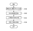
- FIG. 4 is a flowchart showing a flow of processing of the secondary battery life prediction program executed by the BMU 42 when performing the secondary battery life prediction processing.
- the secondary battery life prediction program is stored in a predetermined area of the storage unit 44. Is stored in advance. This program may be executed when an instruction to start secondary battery life prediction processing is input by a user (administrator) of the battery system 10 via an operation unit (not shown), or may be determined in advance. It may be executed at every time interval.
- step 100 shown in FIG. 4 the ideal distribution and the history distribution are compared. Specifically, the peak value P of the ideal distribution is extracted as the representative value of the ideal distribution, and the peak value P ′ of the history distribution is extracted as the representative value of the history distribution. Then, a deviation amount ⁇ P between the extracted peak value P of the ideal distribution and the peak value P ′ of the history distribution is derived.
- the amount of deviation for each factor can be obtained from the following equations (4) to (6).
- formula (5) is, in the case where the peak value of the ideal distribution of the charged amount of the secondary battery 28 and P SOC, the peak value of the historic distribution of current of the secondary battery 28 is P 'SOC, the deviation amount [Delta] P SOC Is shown.
- the following equation (6) indicates the deviation amount ⁇ P T when the peak value of the ideal distribution of the temperature of the secondary battery 28 is P T and the peak value of the current history distribution of the secondary battery 28 is P ′ T. Show.
- the degree of deterioration of the secondary battery 28 predicted in advance is, for example, as shown in FIGS. 5A to 5C, the secondary battery corresponding to the current, the amount of charge, and the temperature of the secondary battery 28.
- the slopes ⁇ , ⁇ , and ⁇ of 28 battery capacity reduction rates (hereinafter referred to as “capacity reduction rates”).
- 5A shows the capacity reduction rate according to the current of the secondary battery 28
- FIG. 5B shows the capacity reduction rate according to the amount of power stored in the secondary battery 28
- FIG. Indicates a capacity reduction rate according to the temperature of the secondary battery 28. This capacity reduction rate is obtained by, for example, an experiment performed in advance.
- the capacity decrease rate becomes larger than the capacity decrease rate below the threshold when the magnitude of each factor exceeds a predetermined threshold (slope ⁇ ).
- a predetermined threshold for example, in a lithium ion battery, the non-aqueous electrolyte containing lithium ions leaks from the battery container 29, and as a result, the deterioration of the secondary battery 28 is promoted.
- the usage frequency (number of times) exceeding the threshold is detected for each factor. Then, the battery system 10 derives the deterioration acceleration coefficient K so as to increase according to the number of times the threshold value is exceeded, as shown in the following equation (8).
- A indicates the sensitivity of the degree of deterioration with respect to the number of times that the current of the secondary battery 28 exceeds the threshold
- B indicates the degree of deterioration with respect to the number of times that the amount of charge of the secondary battery 28 exceeds the threshold
- C represents the sensitivity of the degree of deterioration with respect to the number of times that the temperature of the secondary battery 28 exceeded the threshold
- N I2 represents the number of times that the current of the secondary battery 28 exceeded the threshold
- N SOC Indicates the number of times that the amount of power stored in the secondary battery 28 exceeds the threshold
- NT indicates the number of times that the temperature of the secondary battery 28 exceeds the threshold.
- the degree of deterioration of the secondary battery 28 predicted in advance depends on the current, the amount of charge, and the temperature of the secondary battery 28 as shown in FIGS.
- the deterioration acceleration coefficient K ′ is derived from the slopes ⁇ ′, ⁇ ′, ⁇ ′ of the change rate of the internal resistance (hereinafter referred to as “resistance change rate”) of the secondary battery 28.
- the values obtained by multiplying the slopes ⁇ ′, ⁇ ′, ⁇ ′ of the resistance change rate according to each factor by the deviation amount of each factor are in use. This is derived as the deterioration acceleration coefficient K ′ of the secondary battery 28.
- the resistance change rate is similar to the capacity change rate, and when the magnitude of each factor exceeds a predetermined threshold value, the internal resistance decrease rate is equal to or less than the threshold value. In comparison, it becomes larger (inclination ⁇ ′ ⁇ inclination a ′, inclination ⁇ ′ ⁇ inclination b ′, inclination ⁇ ′ ⁇ inclination c ′).
- the deterioration acceleration coefficient K ′ is derived so as to become larger according to the number of times.
- a ′ indicates the sensitivity of the degree of deterioration with respect to the number of times that the current of the secondary battery 28 exceeds the threshold value
- B ′ indicates deterioration with respect to the number of times that the charged amount of the secondary battery 28 exceeds the threshold value
- C ′ indicates the sensitivity of the degree of deterioration with respect to the number of times the temperature of the secondary battery 28 exceeds the threshold.
- the gradients ⁇ , ⁇ , ⁇ , ⁇ ′, ⁇ ′, ⁇ ′, and sensitivities A, B, C, A ′, B ′, C ′ may be weighted. This weighting varies depending on the usage environment of the battery system 10, for example. For example, since the deterioration of the secondary battery 28 is promoted when the temperature becomes high, the influence on the deterioration acceleration coefficients K and K ′ is more exerted on the gradients ⁇ and ⁇ ′ and the sensitivities C and C ′ according to the temperature. It is preferable to weight so as to increase.
- the lifetime of the secondary battery 28 is predicted based on the deterioration acceleration coefficients K and K ′ derived in step 102.
- the lifetime of the secondary battery 28 is predicted from the change in the battery capacity of the secondary battery 28 and the change in the internal resistance of the secondary battery 28.
- FIG. 8 is a diagram showing a prediction result of the life of the secondary battery 28, and FIG. 8A predicts the life from a change in the battery capacity of the secondary battery 28 (hereinafter referred to as “capacity change”). It is a result.
- the capacity change ⁇ Cap is calculated from the following equation (11), where Cap is the initial value of the battery capacity of the secondary battery 28.
- Cap is the initial value of the battery capacity of the secondary battery 28.
- the battery capacity of the secondary battery 28 decreases as the secondary battery 28 deteriorates.
- K ⁇ + ⁇ + ⁇ (hereinafter referred to as “reference deterioration”).
- the life of the secondary battery 28 is defined as the number of years that becomes a determination value (for example, 70% of the initial value of the battery capacity) at which it is determined that the capacity change has reached the life.
- the broken line in FIG. 8A indicates that the value of the deterioration acceleration coefficient K is smaller than the reference deterioration and the degree of deterioration is small. That is, the broken line indicates that the life of the secondary battery 28 is longer than the reference deterioration.
- the alternate long and short dash line in FIG. 8A indicates that the value of the deterioration acceleration coefficient K is larger than the reference deterioration and the degree of deterioration is large. That is, the alternate long and short dash line indicates that the lifetime of the secondary battery 28 is shorter than that in the case of the reference deterioration.
- FIG. 8B shows the result of predicting the lifetime from the change in internal resistance of the secondary battery 28 (hereinafter referred to as “resistance change”).
- the resistance change ⁇ R is calculated from the following equation (12), where R is the initial value of the internal resistance of the secondary battery 28.
- the internal resistance of the secondary battery 28 increases as the secondary battery 28 deteriorates.
- K ′ ⁇ ′ + ⁇ ′ + ⁇ ′ (reference deterioration).
- the life of the secondary battery 28 is defined as the number of years that becomes a determination value (for example, 200% of the initial value of the internal resistance) at which it is determined that the resistance change has reached the life.
- the broken line in FIG. 8B indicates that the value of the deterioration acceleration coefficient K ′ is smaller than the reference deterioration and the degree of deterioration is small. That is, the broken line indicates that the life of the secondary battery 28 is longer than that in the case of the reference deterioration.
- the alternate long and short dash line in FIG. 8B indicates that the value of the deterioration acceleration coefficient K ′ is larger than the reference deterioration and the degree of deterioration is large. That is, the alternate long and short dash line indicates that the lifetime of the secondary battery 28 is shorter than that in the case of the reference deterioration.
- the life of the secondary battery 28 is predicted from the number of years that the capacity change and the resistance change reach the judgment values.
- the earlier of the number of years when the capacity change and the resistance change reach the determination value is predicted as the life, and the difference between the predicted life and the elapsed years since the use of the secondary battery 28 is started. Is calculated as the remaining life.
- the predicted life of the secondary battery 28 (remaining life in the present embodiment) is notified to the display device 16 via the host control device 12.
- the information indicating that the degree of deterioration of the secondary battery 28 is high is the remaining life of the secondary battery 28
- the program is displayed on the display device 16 and the program is terminated.
- the host controller 12 receives each value (deviation amount ⁇ P I2, ⁇ P SOC , ⁇ P T, etc.) derived from the BMU 42 in the secondary battery life prediction process,
- the usage state of the secondary battery 28 is controlled so that the amount of deviation between the peak value of the distribution and the peak value of the ideal distribution becomes small.
- the host control device 12 when the current deviation amount ⁇ P I2 becomes a predetermined value exceeding 1, that is, when the secondary battery 28 is frequently used in a state where the current is large, the host control device 12 is, for example, The current used in the range from ⁇ 300 A to +300 A is set to be from ⁇ 200 A to +200 A, and the current of the secondary battery 28 is controlled so that the current deviation amount ⁇ P I2 becomes small.
- the host control device 12 when the storage amount deviation amount P SOC becomes a predetermined value less than 1, that is, when the secondary battery 28 is frequently used in a state where the amount of livestock electricity is small, the host control device 12 The storage battery usage range of 40% to 60% is set to 30% to 70%, and the storage amount of the secondary battery 28 is controlled so that the storage amount deviation amount ⁇ P SOC is reduced. To do.
- the degree of deterioration of the secondary battery 28 becomes equal to the reference deterioration, which is an ideal deterioration, so that the life of the secondary battery 28 can be easily managed.
- the secondary battery 28 can be reused. It becomes easy.
- the battery system 10 includes the secondary battery 28 that supplies power to the current load 18 and the ammeter 32 that measures the magnitude of a factor that affects the deterioration of the secondary battery 28. And a thermometer 34, and the peak value of the history distribution based on the usage frequency of the secondary battery 28 according to the magnitude of the factor measured a plurality of times within a predetermined period by the ammeter 32 and the thermometer 34, and the factor
- the peak value of the ideal distribution based on the predicted usage frequency of the secondary battery 28 according to the size of the secondary battery 28 is compared, and the usage state is determined based on the comparison result and the degree of deterioration of the secondary battery 28 predicted in advance.
- the degree of deterioration of the secondary battery 28 is derived, and the life of the secondary battery 28 is predicted based on the derived degree of deterioration.
- the battery system 10 which concerns on this embodiment enables the lifetime prediction of a secondary battery with higher precision.
- the battery system 10 includes the BMU 42 and the CMUs 40A and 40B.
- the present invention is not limited to this, and the battery system 10 does not include the CMUs 40A and 40B.
- the BMU 42 may have the functions of the CMUs 40A and 40B.
- the said embodiment demonstrated the form which estimates the lifetime of the secondary battery 28 from the deviation
- this invention is described.
- the present invention is not limited to this, and the lifetime of the secondary battery 28 may be predicted from the amount of deviation between the average value of the history distribution of the usage frequency of the secondary battery 28 and the average value of the ideal distribution.
- the average value of the history distribution and the average value of the ideal distribution are obtained, for example, by dividing the product of the factor size and the usage frequency by the number of measurement times of the factor. Thereby, for example, when there are two or more peaks in the history distribution, it is possible to easily obtain the amount of deviation between the history distribution and the ideal distribution.
- the battery system 10 demonstrated the form provided with BMU42 and CMU40A, 40B in the said embodiment, this invention is not limited to this, The battery system 10 is not provided with CMU40A, 40B, The BMU 42 may have the functions of the CMUs 40A and 40B.
- the mode of predicting the lifetime of the secondary battery 28 using the current, the storage amount, and the temperature of the secondary battery 28 as factors affecting the deterioration of the secondary battery 28 has been described.
- the present invention is not limited to this, and as a factor that affects the deterioration of the secondary battery 28, the secondary battery 28 is configured using at least one of the current, the storage amount, and the temperature of the secondary battery 28. It is good also as a form which estimates a lifetime.
- the said embodiment demonstrated the form which estimates the lifetime of the secondary battery 28 from the change of the battery capacity of the secondary battery 28, and the change of the internal resistance of the secondary battery 28, this invention is limited to this. Instead, the lifetime of the secondary battery 28 may be predicted from the change in the battery capacity of the secondary battery 28 or the change in the internal resistance of the secondary battery 28.
Landscapes
- Physics & Mathematics (AREA)
- General Physics & Mathematics (AREA)
- Engineering & Computer Science (AREA)
- Manufacturing & Machinery (AREA)
- Chemical & Material Sciences (AREA)
- Chemical Kinetics & Catalysis (AREA)
- Electrochemistry (AREA)
- General Chemical & Material Sciences (AREA)
- Secondary Cells (AREA)
- Charge And Discharge Circuits For Batteries Or The Like (AREA)
- Tests Of Electric Status Of Batteries (AREA)
Abstract
より精度の高い二次電池の寿命予測を可能とする二次電池寿命予測装置、電池システム、及び二次電池寿命予測方法を提供することを目的とする。電池システム(10)は、電力負荷(18)へ電力を供給する二次電池(28)と、二次電池(28)の劣化に影響を及ぼす因子の大きさを計測する電流計(32)及び温度計(34)を備えており、電流計(32)及び温度計(34)によって所定期間内に複数回計測された因子の大きさに応じた二次電池(28)の使用頻度に基づく履歴分布のピーク値と、因子の大きさに応じた二次電池(28)の予め予測された使用頻度に基づく理想分布のピーク値とを比較し、比較結果及び予め予測された二次電池(28)の劣化の度合いに基づいて、使用状態にある二次電池(28)の劣化の度合いを導出し、導出した劣化の度合いに基づいて、二次電池(28)の寿命を予測する。
Description
本発明は、二次電池寿命予測装置、電池システム、及び二次電池寿命予測方法に関するものである。
二次電池は、充放電の繰り返し、高温環境下での使用等によって劣化するため、二次電池には使用可能な期間(寿命)がある。
そこで、二次電池の寿命を予測する技術として、特許文献1には、二次電池の内部抵抗値から、二次電池の蓄電部の抵抗値を算出すると共に、二次電池の使用環境における、蓄電部の抵抗値の増加率を算出し、算出した蓄電部の抵抗値及び蓄電部の抵抗値の増加率と、から二次電池の余寿命を推定する技術が記載されている。
そこで、二次電池の寿命を予測する技術として、特許文献1には、二次電池の内部抵抗値から、二次電池の蓄電部の抵抗値を算出すると共に、二次電池の使用環境における、蓄電部の抵抗値の増加率を算出し、算出した蓄電部の抵抗値及び蓄電部の抵抗値の増加率と、から二次電池の余寿命を推定する技術が記載されている。
特許文献1に記載の技術では、リアルタイムで計測された二次電池の電流及び電圧から、電流変化値及び電圧変化値を取得し、取得した電流変化値及び電圧変化値から、二次電池の内部抵抗値を算出し、二次電池の余寿命を推定している。このため、計測される電流及び電圧の誤差によって二次電池の余寿命が突然低下したり、増加する可能性があった。
本発明は、このような事情に鑑みてなされたものであって、より精度の高い二次電池の寿命予測を可能とする二次電池寿命予測装置、電池システム、及び二次電池寿命予測方法を提供することを目的とする。
上記課題を解決するために、本発明の二次電池寿命予測装置、電池システム、及び二次電池寿命予測方法は以下の手段を採用する。
すなわち、本発明の第1の態様に係る二次電池寿命予測装置は、二次電池の劣化に影響を及ぼす因子の大きさを計測する計測手段と、前記計測手段によって所定期間内に複数回計測された前記因子の大きさに応じた前記二次電池の使用頻度に基づく第1の値と、前記因子の大きさに応じた前記二次電池の予め予測された使用頻度に基づく第2の値とを比較する比較手段と、前記比較手段による比較結果、及び前記予め予測された二次電池の劣化の度合いに基づいて、使用状態にある前記二次電池の劣化の度合いを導出する導出手段と、前記導出手段によって導出された前記度合いに基づいて、前記二次電池の寿命を予測する予測手段と、を備える。
すなわち、本発明の第1の態様に係る二次電池寿命予測装置は、二次電池の劣化に影響を及ぼす因子の大きさを計測する計測手段と、前記計測手段によって所定期間内に複数回計測された前記因子の大きさに応じた前記二次電池の使用頻度に基づく第1の値と、前記因子の大きさに応じた前記二次電池の予め予測された使用頻度に基づく第2の値とを比較する比較手段と、前記比較手段による比較結果、及び前記予め予測された二次電池の劣化の度合いに基づいて、使用状態にある前記二次電池の劣化の度合いを導出する導出手段と、前記導出手段によって導出された前記度合いに基づいて、前記二次電池の寿命を予測する予測手段と、を備える。
本発明の第1の態様によれば、計測手段によって、二次電池の劣化に影響を及ぼす因子の大きさが計測される。二次電池の劣化に影響を及ぼす因子とは、例えば、二次電池の電流、二次電池の蓄電量、及び二次電池の温度である。
また、本発明の第1の態様では、所定期間内に複数回計測された因子の大きさに応じた二次電池の使用頻度、換言すると二次電池の使用の履歴を求める。上記所定期間とは、例えば二次電池の使用開始から現在に至るまでの期間であり、因子の計測は、例えば1日に10回行われる。この計測手段による因子を計測する期間、及び回数を多くすることによって、二次電池の寿命予測の精度が、より高められる。
また、比較手段によって、計測手段で所定期間内に複数回計測された因子の大きさに応じた二次電池の使用頻度に基づく第1の値と、予め予測された因子の大きさに応じた二次電池の使用頻度に基づく第2の値とが比較される。
また、比較手段によって、計測手段で所定期間内に複数回計測された因子の大きさに応じた二次電池の使用頻度に基づく第1の値と、予め予測された因子の大きさに応じた二次電池の使用頻度に基づく第2の値とが比較される。
すなわち、第1の値とは、実測された因子に基づくため二次電池の実際の使用状態に応じた値であり、第2の値とは、二次電池の設計値から求められる理想的な使用状態に応じた値である。そのため、第1の値と第2の値とを比較することによって、二次電池の実際の使用状態と二次電池の理想的な使用状態とを比較することとなる。
さらに、導出手段によって、比較手段による比較結果、及び予め予測された二次電池の劣化の度合いに基づいて、使用状態にある二次電池の劣化の度合いが導出される。予め予測された二次電池の劣化の度合いは、例えば予め行われた実験によって求められている。そして、予測手段によって、導出手段で導出された度合いに基づいて、二次電池の寿命が予測される。
このように、本発明の第1の態様は、二次電池の劣化に影響を及ぼす因子の大きさを所定期間内に複数回計測し、計測した因子の大きさに応じた二次電池の使用頻度に基づいて、二次電池の寿命を予測するので、より精度の高い二次電池の寿命予測を可能とする。
また、本発明の第1の態様に係る二次電池寿命予測装置は、前記導出手段が、前記計測手段によって計測された前記因子の大きさが予め定められた閾値を超える頻度に応じて、前記二次電池の劣化の度合いをより大きく導出してもよい。
二次電池の劣化に影響を及ぼす因子の大きさが、ある閾値を超えると二次電池の劣化が促進される。このことから、本発明の第1の態様に係る二次電池寿命予測装置は、計測手段で計測された因子の大きさが予め定められた閾値を超える頻度に応じて、二次電池の劣化の度合いをより大きく導出するので、より精度の高い二次電池の寿命予測が可能となる。
また、本発明の第1の態様に係る二次電池寿命予測装置は、前記第1の値と前記第2の値とのずれ量が小さくなるように、前記二次電池の使用状態を制御する制御手段を備えてもよい。
本発明の第1の態様によれば、制御手段によって、上記第1の値と上記第2の値とのずれ量が小さくなるように、二次電池の使用状態が制御されるので、二次電池の劣化の度合いを理想的な劣化に等しくすることができ、二次電池の寿命の管理が容易になる。
また、本発明の第1の態様に係る二次電池寿命予測装置は、前記導出手段が、予め予測された劣化の度合いに前記第1の値と前記第2の値とのずれ量を乗算した値を、使用状態にある前記二次電池の劣化の度合いとして導出してもよい。
本発明の第1の態様によれば、予め劣化の度合いが予測されている。この予測された劣化の度合いとは、例えば予め行われた実験によって求められている。そして、予め予測された劣化の度合いに上記第1の値と上記第2の値とのずれ量を乗算した値が、使用状態にある二次電池の劣化の度合いとして導出されるので、本発明の第1の態様に係る二次電池寿命予測装置は、簡易により精度の高い二次電池の寿命予測を可能とする。
また、本発明の第1の態様に係る二次電池寿命予測装置は、前記導出手段が、前記導出手段によって導出された前記度合いに基づいた、前記二次電池の電池容量の変化、及び前記二次電池の内部抵抗の変化の少なくとも一方から前記二次電池の寿命を予測してもよい。
二次電池の電池容量は、二次電池の劣化と共に減少し、二次電池の内部抵抗は、二次電池の劣化と共に上昇する。そのため、本発明の第1の態様によれば、使用状態にある二次電池の劣化の度合いに基づいた、二次電池の電池容量の変化、及び二次電池の内部抵抗の変化の少なくとも一方から二次電池の寿命を予測することによって、より精度の高い二次電池の寿命予測が可能となる。
また、本発明の第1の態様に係る二次電池寿命予測装置は、前記因子を、前記二次電池の電流、前記二次電池の蓄電量、及び前記二次電池の温度の少なくとも一つとしてもよい。
本発明の第1の態様によれば、二次電池の電流、二次電池の蓄電量、及び二次電池の温度は、簡易に計測できるため、簡易により精度の高い二次電池の寿命予測が可能となる。
本発明の第1の態様によれば、二次電池の電流、二次電池の蓄電量、及び二次電池の温度は、簡易に計測できるため、簡易により精度の高い二次電池の寿命予測が可能となる。
また、本発明の第2の態様に係る電池システムは、負荷へ電力を供給する二次電池と、前記二次電池の寿命を予測する第1の態様に係る二次電池寿命予測装置と、を備える。
本発明の第2の態様によれば、負荷へ電力を供給する二次電池と、二次電池の寿命を予測する上記記載の二次電池寿命予測装置と、を備えるので、より精度の高い二次電池の寿命予測が可能となる。
さらに、本発明の第3の態様に係る二次電池寿命予測方法は、二次電池の劣化に影響を及ぼす因子の大きさを計測する計測手段によって所定期間内に複数回計測された前記因子の大きさに応じた前記二次電池の使用頻度に基づく第1の値と、前記因子の大きさに応じた前記二次電池の予め予測された使用頻度に基づく第2の値とを比較する第1工程と、前記第1工程による比較結果、及び前記予め予測された二次電池の劣化の度合いに基づいて、使用状態にある前記二次電池の劣化の度合いを導出する第2工程と、前記第2工程によって導出された前記度合いに基づいて、前記二次電池の寿命を予測する第3工程と、を含む。
本発明の第3の態様によれば、二次電池の劣化に影響を及ぼす因子の大きさを所定期間の間複数回計測し、該計測した因子の大きさに応じた二次電池の使用頻度に基づいて、二次電池の寿命を予測するので、より精度の高い二次電池の寿命予測が可能となる。
本発明によれば、より精度の高い二次電池の寿命予測を可能とする、という優れた効果を有する。
以下に、本発明に係る二次電池寿命予測装置、電池システム、及び二次電池寿命予測方法の一実施形態について、図面を参照して説明する。
図1は、本実施形態に係る電池システム10の構成を示すブロック図である。
本実施形態に係る電池システム10は、二次電池による電力の充放電を利用するシステムであり、一例として、電気自動車に搭載され、該電気自動車に電力を供給するものとして用いられる。しかし、これに限らず、電池システム10は、例えば、フォークリフト等の産業車両、電車、船、航空機、及び宇宙機等、他の移動体に電力を供給するものであってもよい。また、電池システム10は、例えば家庭用の電力貯蔵システム、並びに風力発電装置及び太陽光発電装置等の自然エネルギーを用いた発電装置と組み合わせた系統連係円滑化蓄電システムに用いてもよい。
本実施形態に係る電池システム10は、二次電池による電力の充放電を利用するシステムであり、一例として、電気自動車に搭載され、該電気自動車に電力を供給するものとして用いられる。しかし、これに限らず、電池システム10は、例えば、フォークリフト等の産業車両、電車、船、航空機、及び宇宙機等、他の移動体に電力を供給するものであってもよい。また、電池システム10は、例えば家庭用の電力貯蔵システム、並びに風力発電装置及び太陽光発電装置等の自然エネルギーを用いた発電装置と組み合わせた系統連係円滑化蓄電システムに用いてもよい。
本実施形態に係る電池システム10は、組電池12、上位制御装置14、表示装置16、電力負荷18、及びBMS(Battery Management System)20を備えている。組電池12とBMS20はバッテリーモジュール22として形成されており、電池システム10に対して交換可能とされている。
組電池12は、複数の二次電池(本実施形態では、一例としてリチウムイオン電池)28A~28Fが接続され、電力負荷18に電力を供給する。以下の説明において、各二次電池28を区別する場合は、符号の末尾にA~Fの何れかを付し、各二次電池28を区別しない場合は、A~Fを省略する。
二次電池28は、アルミニウム系材料で形成された電池容器29を有している。電池容器29は箱型の中空容器であり、電池容器29の内部には、正極電極及び負極電極が配置されると共に、リチウムイオンを含む非水電解液が貯留される。
また、本実施形態では、図1に示すように二次電池28A~28Dが直列に接続されると共に、二次電池28E~28Hが直列に接続され、さらに、これら直列に接続された二次電池28A~28D及び二次電池28E~28Hが並列に接続されているが、図1に示される二次電池28の数及び二次電池28の接続方法は一例であり、複数の二次電池28を直列のみによって接続してもよいし、並列のみによって接続してもよい。
二次電池28は、アルミニウム系材料で形成された電池容器29を有している。電池容器29は箱型の中空容器であり、電池容器29の内部には、正極電極及び負極電極が配置されると共に、リチウムイオンを含む非水電解液が貯留される。
また、本実施形態では、図1に示すように二次電池28A~28Dが直列に接続されると共に、二次電池28E~28Hが直列に接続され、さらに、これら直列に接続された二次電池28A~28D及び二次電池28E~28Hが並列に接続されているが、図1に示される二次電池28の数及び二次電池28の接続方法は一例であり、複数の二次電池28を直列のみによって接続してもよいし、並列のみによって接続してもよい。
さらに、図1に示すように、各二次電池28は、二次電池28の正極電極及び負極電極の端子間の電圧を計測する電圧計30A~30Hが接続されている。
また、組電池12には、二次電池28A~28Dが直列に接続されている経路に流れる電流を計測する電流計32A、及び二次電池28E~28Hが直列に接続されている経路に流れる電流を計測する電流計32Bが設けられている。
さらに、組電池12には、各二次電池28毎に電池容器29の表面温度を計測する温度計34A~34Hが設けられている。本実施形態では、温度計34A~34Hとして熱電対を用いるが、これに限らず、抵抗測温体等、他の温度計を用いてもよい。また、温度計34A~34Hは、対応する電池容器29の表面温度でなく、対応する電池容器29の近傍の温度を計測してもよい。
そして、電圧計30A~30Hで計測された電圧、電流計32A,32Bで計測された電流、及び温度計34A~34Hで計測された温度を示す各計測値は、BMS20へ送信される。
以下の説明において、各電圧計30、及び各温度計34を区別する場合は、符号の末尾にA~Fの何れかを付し、各電圧計30、及び各温度計34を区別しない場合は、A~Fを省略する。また、以下の説明において、各電流計32を区別する場合は、符号の末尾にA,Bの何れかを付し、各電流計32を区別しない場合は、A,Bを省略する。
また、組電池12には、二次電池28A~28Dが直列に接続されている経路に流れる電流を計測する電流計32A、及び二次電池28E~28Hが直列に接続されている経路に流れる電流を計測する電流計32Bが設けられている。
さらに、組電池12には、各二次電池28毎に電池容器29の表面温度を計測する温度計34A~34Hが設けられている。本実施形態では、温度計34A~34Hとして熱電対を用いるが、これに限らず、抵抗測温体等、他の温度計を用いてもよい。また、温度計34A~34Hは、対応する電池容器29の表面温度でなく、対応する電池容器29の近傍の温度を計測してもよい。
そして、電圧計30A~30Hで計測された電圧、電流計32A,32Bで計測された電流、及び温度計34A~34Hで計測された温度を示す各計測値は、BMS20へ送信される。
以下の説明において、各電圧計30、及び各温度計34を区別する場合は、符号の末尾にA~Fの何れかを付し、各電圧計30、及び各温度計34を区別しない場合は、A~Fを省略する。また、以下の説明において、各電流計32を区別する場合は、符号の末尾にA,Bの何れかを付し、各電流計32を区別しない場合は、A,Bを省略する。
BMS20は、CMU(Cell Monitor Unit)40A,40B、及びBMU(Battery Management Unit)42を備えている。
CMU40Aは、電圧計30A~30D、電流計32A、及び温度計34A~34Dに接続されることによって各種計測値が入力される。一方、CMU40Bは、電圧計30E~30H、電流計32B、及び温度計34E~34Hに接続されることによって各種計測値が入力される。
そして、CMU40A,40Bは、各々不図示のADC(Analog Digital Converter)を備えており、アナログ信号である電圧計30、電流計32、及び温度計34の各種計測値を各々デジタル信号に変換し、該デジタル信号をBMU42へ送信する。本実施形態では、BMS20は、CMU40A,40Bを備えるが、CMUは一つでもよいし、3つ以上でもよく、CMUが一つの場合は、各種計測値が全て一つのCMUに入力され、CMUが3つ以上の場合は、各種計測値が分散されて対応する各CMUに入力される。
CMU40Aは、電圧計30A~30D、電流計32A、及び温度計34A~34Dに接続されることによって各種計測値が入力される。一方、CMU40Bは、電圧計30E~30H、電流計32B、及び温度計34E~34Hに接続されることによって各種計測値が入力される。
そして、CMU40A,40Bは、各々不図示のADC(Analog Digital Converter)を備えており、アナログ信号である電圧計30、電流計32、及び温度計34の各種計測値を各々デジタル信号に変換し、該デジタル信号をBMU42へ送信する。本実施形態では、BMS20は、CMU40A,40Bを備えるが、CMUは一つでもよいし、3つ以上でもよく、CMUが一つの場合は、各種計測値が全て一つのCMUに入力され、CMUが3つ以上の場合は、各種計測値が分散されて対応する各CMUに入力される。
一方、BMU42は、CMU40A,40Bから入力されたデジタル化された各計測値に基づいて、後述する二次電池寿命予測処理を行いその結果を上位制御装置14へ送信する。また、BMU42は、後述する二次電池寿命予測プログラム、CMU40A,40Bから入力された各計測値、その他各種情報等を記憶する記憶部44を備えている。
上位制御装置14は、ユーザの指示(例えば、ユーザによるアクセルの踏み込み量)に応じて電力負荷18を制御すると共に、BMS20から送信される組電池12に関連する関連情報(電圧計30、電流計32、及び温度計34の計測値、BMS20で演算される各二次電池28の蓄電量、並びに後述する二次電池寿命予測処理の結果等)を受信する。また、上位制御装置14は、表示装置16と接続されており、表示装置16の画面に上記関連情報等種々の情報に基づいて画像を表示させる等、表示装置16にユーザに対する種々の報知を行わせる。
表示装置16は、例えば音響装置を備えた液晶パネル等のモニターであり、上位制御装置14によって制御されることによって、ユーザに対する種々の報知を行う。
電力負荷18は、例えば、回転軸が電気自動車の車軸に機械的に連接された電気モータ、ワイパーを駆動させるための電気モータ、インバータ等の電力変換機等である。
ここで、二次電池28は、充放電の繰り返し、高温環境下での使用等によって劣化し、寿命に達すると、使用ができなくなる。このような、二次電池28の劣化に影響を及ぼす因子(ファクター)としては、例えば、二次電池28の電流、蓄電量、及び温度が挙げられる。
そこで、本実施形態に係る電池システム10では、二次電池28の劣化に影響を及ぼす因子に基づいて、二次電池28の寿命を予測する二次電池寿命予測処理を行う。
本実施形態に係る電池システム10は、二次電池寿命予測処理を実行するにあたり、電流計32で計測された電流、及び温度計32で計測された温度が、CMU40A,40Bを介してBMU42の記憶部44に逐次記憶される。
そこで、本実施形態に係る電池システム10では、二次電池28の劣化に影響を及ぼす因子に基づいて、二次電池28の寿命を予測する二次電池寿命予測処理を行う。
本実施形態に係る電池システム10は、二次電池寿命予測処理を実行するにあたり、電流計32で計測された電流、及び温度計32で計測された温度が、CMU40A,40Bを介してBMU42の記憶部44に逐次記憶される。
また、二次電池28の蓄電量もBMU42の記憶部44に記憶される。
ここで、二次電池28の蓄電量は、電流計32で計測された電流から下記(1),(2)式から算出される。下記式において、SOC(State Of Charge)が蓄電量を示し、Q0が二次電池28の初期の電池容量を示し、ΔQが二次電池28の電池容量の変化量を示し、Iが二次電池28の電流を示す。


ここで、二次電池28の蓄電量は、電流計32で計測された電流から下記(1),(2)式から算出される。下記式において、SOC(State Of Charge)が蓄電量を示し、Q0が二次電池28の初期の電池容量を示し、ΔQが二次電池28の電池容量の変化量を示し、Iが二次電池28の電流を示す。
二次電池28の起電圧と蓄電量とは、図2に示すような1対1の比例関係を有しており、起電圧V1と二次電池28の電圧V0とは、内部抵抗をRとした場合に、下記(3)式のような関係を有する。

そこで、BMU42は、(1),(2)式で求められた蓄電量を、(3)式で求められる起電圧を用いて、蓄電量と起電圧とが1対1の関係となるように適宜補正することが望ましい。上記起電圧V1としては、二次電池28毎に設けられている電圧計30で計測された電圧の値が用いられるが、これに限らず、電力負荷18側に電圧計を設け、該電圧計で計測された電圧の値を用いてもよい。
そこで、BMU42は、(1),(2)式で求められた蓄電量を、(3)式で求められる起電圧を用いて、蓄電量と起電圧とが1対1の関係となるように適宜補正することが望ましい。上記起電圧V1としては、二次電池28毎に設けられている電圧計30で計測された電圧の値が用いられるが、これに限らず、電力負荷18側に電圧計を設け、該電圧計で計測された電圧の値を用いてもよい。
そして、本実施形態に係るBMU42は、所定期間内に複数回計測された因子の大きさに応じた二次電池28の使用頻度、換言すると二次電池28の使用の履歴を求める。図3は、二次電池28の使用の履歴を、計測された因子と使用頻度との分布として示した図であり、図3(A)は、因子が電流の場合を示し、図3(B)は、因子が蓄電量の場合を示し、図3(C)は、因子が温度の場合を示す。
本実施形態では、上記所定期間を、例えば二次電池28の使用開始から現在に至るまでの期間とし、各因子の計測を、例えば1日に10回行う。本実施形態に係る二次電池寿命予測処理では、因子を計測する期間、及び回数を多くすることによって、二次電池の寿命予測の精度が、より高められる。
また、図3(A)~(C)において、破線は、実測された因子に基づいた分布(以下、「履歴分布」という。)、すなわち、二次電池28の実際の使用状態に応じた因子の分布を示す。一方、実線は、二次電池28の設計値から求められる理想的な使用状態に応じた因子と使用頻度との関係を示した分布(以下、「理想分布」という。)を示す。このため、履歴分布は、因子である二次電池28の電流、蓄電量、及び温度が計測され記憶部44に記憶される毎に、各因子の大きさ毎の使用頻度が追加されるので、時々刻々と変化するが、理想分布は、一定のままである。
また、図3(A)に示すように、二次電池28の電流の履歴分布は、電流の2乗を横軸としている。この理由は、二次電池28は、放電及び充電両方によって劣化するため、充電及び放電の違いを除去するためである。
図4は、二次電池寿命予測処理を行う場合に、BMU42によって実行される二次電池寿命予測プログラムの処理の流れを示すフローチャートであり、この二次電池寿命予測プログラムは記憶部44の所定領域に予め記憶されている。本プログラムは、二次電池寿命予測処理の開始指示が、電池システム10のユーザ(管理者)によって、不図示の操作部を介して入力された場合に実行されるとしてもよいし、予め定められた時間間隔毎に実行されるとしてもよい。
まず、図4に示すステップ100では、理想分布と履歴分布との比較を行う。
具体的には、理想分布の代表値として、理想分布のピーク値Pを抽出し、履歴分布の代表値として、履歴分布のピーク値P’を抽出する。
そして、抽出した理想分布のピーク値Pと履歴分布のピーク値P’とのずれ量ΔPを導出する。各因子毎のずれ量は、下記(4)~(6)式から求められる。
具体的には、理想分布の代表値として、理想分布のピーク値Pを抽出し、履歴分布の代表値として、履歴分布のピーク値P’を抽出する。
そして、抽出した理想分布のピーク値Pと履歴分布のピーク値P’とのずれ量ΔPを導出する。各因子毎のずれ量は、下記(4)~(6)式から求められる。
下記(4)式は、二次電池28の電流の理想分布のピーク値をPI2とし、二次電池28の電流の履歴分布のピーク値をP’I2とした場合の、ずれ量ΔPI2を示している。

下記(5)式は、二次電池28の蓄電量の理想分布のピーク値をPSOCとし、二次電池28の電流の履歴分布のピーク値をP’SOCとした場合の、ずれ量ΔPSOCを示している。

下記(6)式は、二次電池28の温度の理想分布のピーク値をPTとし、二次電池28の電流の履歴分布のピーク値をP’Tとした場合の、ずれ量ΔPTを示している。

下記(5)式は、二次電池28の蓄電量の理想分布のピーク値をPSOCとし、二次電池28の電流の履歴分布のピーク値をP’SOCとした場合の、ずれ量ΔPSOCを示している。
下記(6)式は、二次電池28の温度の理想分布のピーク値をPTとし、二次電池28の電流の履歴分布のピーク値をP’Tとした場合の、ずれ量ΔPTを示している。
次のステップ102では、ステップ100の比較結果であるずれ量ΔP、及び予め予測された二次電池28の劣化の度合いに基づいて、使用状態にある二次電池28の劣化の度合いを示す劣化加速係数を導出する。
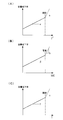
予め予測された二次電池28の劣化の度合いとは、例えば、図5(A)~(C)に示されるように、二次電池28の電流、蓄電量、及び温度に応じた二次電池28の電池容量の低下率(以下、「容量低下率」という。)の傾きα,β,γである。図5(A)は、二次電池28の電流に応じた容量低下率を示し、図5(B)は、二次電池28の蓄電量に応じた容量低下率を示し、図5(C)は、二次電池28の温度に応じた容量低下率を示す。この容量低下率は、例えば予め行われた実験によって求められている。
予め予測された二次電池28の劣化の度合いとは、例えば、図5(A)~(C)に示されるように、二次電池28の電流、蓄電量、及び温度に応じた二次電池28の電池容量の低下率(以下、「容量低下率」という。)の傾きα,β,γである。図5(A)は、二次電池28の電流に応じた容量低下率を示し、図5(B)は、二次電池28の蓄電量に応じた容量低下率を示し、図5(C)は、二次電池28の温度に応じた容量低下率を示す。この容量低下率は、例えば予め行われた実験によって求められている。
そして、本ステップでは、下記(7)式に示すように、各因子に応じた容量低下率の傾きα,β,γに各因子のずれ量ΔPI2,ΔPSOC,ΔPTを乗算した値を、使用状態にある二次電池28の劣化加速係数Kとして導出する。

また、図5(A)~(C)に示すように、容量低下率は、各因子の大きさが所定の閾値を超えると、閾値以下の容量低下率に比較して、大きくなる(傾きα<傾きa、傾きβ<傾きb、傾きγ<傾きc)。因子の大きさが閾値を超えると、例えば、リチウムイオン電池では、電池容器29からリチウムイオンを含む非水電解液が漏れだし、その結果二次電池28の劣化が促進される。
そこで、本実施形態に係る電池システム10では、図6の一例に示すように、各因子毎に閾値を超えた使用頻度(回数)を検知する。そして電池システム10は、下記(8)式に示すように、閾値を超えた回数に応じて、劣化加速係数Kがより大きくなるように導出する。

(8)式において、Aは、二次電池28の電流が閾値を超えた回数に対する劣化の度合いの感度を示し、Bは、二次電池28の蓄電量が閾値を超えた回数に対する劣化の度合いの感度を示し、Cは、二次電池28の温度が閾値を超えた回数に対する劣化の度合いの感度を示し、NI2は、二次電池28の電流が閾値を超えた回数を示し、NSOCは、二次電池28の蓄電量が閾値を超えた回数を示し、NTは、二次電池28の温度が閾値を超えた回数を示す。感度A,B,Cの大きさは、例えば予め行われた実験によって求められている。
また、本実施形態では、予め予測された二次電池28の劣化の度合いとして、図7(A)~(C)に示されるように、二次電池28の電流、蓄電量、及び温度に応じた二次電池28の内部抵抗の変化率(以下、「抵抗変化率」という。)の傾きα’,β’,γ’からも劣化加速係数K’を導出する。
そして、本ステップでは、下記(9)式に示すように、各因子に応じた抵抗変化率の傾きα’,β’,γ’に各因子のずれ量を乗算した値を、使用状態にある二次電池28の劣化加速係数K’として導出する。

そして、本ステップでは、下記(9)式に示すように、各因子に応じた抵抗変化率の傾きα’,β’,γ’に各因子のずれ量を乗算した値を、使用状態にある二次電池28の劣化加速係数K’として導出する。
さらに、図7(A)~(C)に示すように、抵抗変化率は、容量変化率と同様に、各因子の大きさが所定の閾値を超えると、閾値以下の内部抵抗の低下率に比較して、大きくなる(傾きα’<傾きa’、傾きβ’<傾きb’、傾きγ’<傾きc’)。
そこで、本実施形態に係る電池システム10では、上記と同様に、各因子毎に大きさが閾値を超えた使用頻度(回数)を検知し、下記(10)式に示すように、閾値を超えた回数に応じて、劣化加速係数K’がより大きくなるように導出する。

(10)式において、A’は、二次電池28の電流が閾値を超えた回数に対する劣化の度合いの感度を示し、B’は、二次電池28の蓄電量が閾値を超えた回数に対する劣化の度合いの感度を示し、C’は、二次電池28の温度が閾値を超えた回数に対する劣化の度合いの感度を示す。感度A’,B’,C’ の大きさは、例えば予め行われた実験によって求められている。
また、傾きα,β,γ,α’,β’,γ’、及び感度A,B,C,A’,B’,C’に対して、重み付けを行ってもよい。この重み付けは、例えば電池システム10の使用環境によって異なるものとする。例えば、二次電池28は、温度が高温となると劣化が促進されるため、温度に応じた傾きγ,γ’及び感度C,C’に対して、より劣化加速係数K,K’に対する影響が大きくなるように重み付けをすることが好ましい。
図4に示すステップ104では、ステップ102で導出した劣化加速係数K,K’に基づいて、二次電池28の寿命を予測する。本実施形態では、二次電池28の電池容量の変化、及び二次電池28の内部抵抗の変化から二次電池28の寿命を予測する。
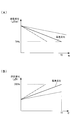
図8は、二次電池28の寿命の予測結果を示す図であり、図8(A)は、二次電池28の電池容量の変化(以下、「容量変化」という。)から寿命を予測した結果である。容量変化ΔCapは、二次電池28の電池容量の初期値をCapとすると、下記(11)式から算出される。二次電池28の電池容量は、二次電池28の劣化と共に低下する。

図8(A)において、実線は、履歴分布のピーク値と理想分布のピーク値が一致する場合、すなわち、ずれ量ΔPI2=1,ΔPSOC=1,ΔPT=1であり、劣化加速係数K=α+β+γの場合(以下、「基準劣化」という。)である。本実施形態では、容量変化が寿命に達したと判定される判定値(例えば、電池容量の初期値の70%)となる年数を二次電池28の寿命とする。
一方、図8(A)の破線は、劣化加速係数Kの値が、基準劣化よりも小さく劣化の度合いが小さいことを示している。すなわち、破線は、二次電池28の寿命が基準劣化よりも長くなることを示している。
また、図8(A)の一点鎖線は、劣化加速係数Kの値が、基準劣化よりも大きく、劣化の度合いが大きいことを示している。すなわち、一点鎖線は、二次電池28の寿命が基準劣化の場合よりも短くなることを示す。
一方、図8(B)は、二次電池28の内部抵抗の変化(以下、「抵抗変化」という。)から寿命を予測した結果である。抵抗変化ΔRは、二次電池28の内部抵抗の初期値をRとすると、下記(12)式から算出される。二次電池28の内部抵抗は、二次電池28の劣化と共に上昇する。

図8(B)において、実線は、履歴分布のピーク値と理想分布のピーク値が一致する場合、すなわち、ずれ量ΔPI2=1,ΔPSOC=1,ΔPT=1であり、劣化加速係数K’=α’+β’+γ’の場合(基準劣化)である。本実施形態では、抵抗変化が寿命に達したと判定される判定値(例えば、内部抵抗の初期値の200%)となる年数を二次電池28の寿命とする。
一方、図8(B)の破線は、劣化加速係数K’の値が、基準劣化よりも小さく、劣化の度合いが小さいことを示している。すなわち、破線は、二次電池28の寿命が基準劣化の場合よりも長くなることを示す。
また、図8(B)の一点鎖線は、劣化加速係数K’の値が、基準劣化よりも大きく、劣化の度合いが大きいことを示している。すなわち、一点鎖線は、二次電池28の寿命が基準劣化の場合よりも短くなることを示す。
そして、本ステップでは、容量変化と抵抗変化とが判定値に達する年数から二次電池28の寿命を予測する。本実施形態では、一例として、容量変化と抵抗変化とが判定値に達する年数の早い方を寿命として予測し、予測した寿命と二次電池28の使用を開始してからの経過年数との差を余寿命として算出する。
次のステップ106では、上位制御装置12を介して、予測した二次電池28の寿命(本実施形態では、余寿命)を表示装置16に報知させる。また、本ステップでは、ステップ102で導出した劣化加速係数K,K’の少なくとも一方が、二次電池28の劣化の度合いが高いことを示す予め定められた値(例えば、ずれ量ΔPI2=1,ΔPSOC=1,ΔPT=1のときの劣化加速係数の2倍)を超えている場合に、二次電池28の劣化の度合いが高いことを示す情報を、二次電池28の余寿命と共に表示装置16に表示させ、本プログラムを終了する。
また、本実施形態に係る電池システム10では、上位制御装置12が、BMU42から二次電池寿命予測処理で導出された各値(ずれ量ΔPI2,ΔPSOC,ΔPT等)を受信し、履歴分布のピーク値と理想分布のピーク値とのずれ量が小さくなるように、二次電池28の使用状態を制御する。
具体例としては、電流のずれ量ΔPI2が1を超える所定値となった場合、すなわち、二次電池28の電流が大きい状態で使用される頻度が多い場合、上位制御装置12が、例えば、電流の使用範囲が-300Aから+300Aまでの間であったものを、-200Aから+200Aまでの間とし、電流のずれ量ΔPI2が小さくなるように二次電池28の電流を制御する。また、例えば、蓄電量のずれ量PSOCが1未満の所定値となった場合、すなわち、二次電池28の畜電量が小さい状態で使用される頻度が多い場合、上位制御装置12が、例えば、蓄電池の使用範囲40%から60%までの間であったものを、30%から70%までの間とし、蓄電量のずれ量ΔPSOCが小さくなるように二次電池28の蓄電量を制御する。
これによって、二次電池28の劣化の度合いが、理想的な劣化である基準劣化により等しくなるため、二次電池28の寿命の管理が容易になり、例えば、二次電池28の再利用等が容易になる。
以上説明したように、本実施形態に係る電池システム10は、電流負荷18へ電力を供給する二次電池28と、二次電池28の劣化に影響を及ぼす因子の大きさを計測する電流計32及び温度計34を備えており、電流計32及び温度計34によって所定期間内に複数回計測された因子の大きさに応じた二次電池28の使用頻度に基づく履歴分布のピーク値と、因子の大きさに応じた二次電池28の予め予測された使用頻度に基づく理想分布のピーク値とを比較し、比較結果及び予め予測された二次電池28の劣化の度合いに基づいて、使用状態にある二次電池28の劣化の度合いを導出し、導出した劣化の度合いに基づいて、二次電池28の寿命を予測する。これにより、本実施形態に係る電池システム10は、より精度の高い二次電池の寿命予測を可能とする。
以上、本発明を、上記実施形態を用いて説明したが、本発明の技術的範囲は上記実施形態に記載の範囲には限定されない。発明の要旨を逸脱しない範囲で上記実施形態に多様な変更または改良を加えることができ、該変更または改良を加えた形態も本発明の技術的範囲に含まれる。
例えば、上記実施形態では、電池システム10が、BMU42とCMU40A,40Bとを備える形態について説明したが、本発明は、これに限定されるものではなく、電池システム10がCMU40A,40Bを備えず、BMU42がCMU40A,40Bの機能を有する形態としてもよい。
また、上記実施形態では、二次電池28の使用頻度の履歴分布のピーク値と理想分布のピーク値とのずれ量から、二次電池28の寿命を予測する形態について説明したが、本発明は、これに限定されるものではなく、二次電池28の使用頻度の履歴分布の平均値と理想分布の平均値とのずれ量から、二次電池28の寿命を予測する形態としてもよい。
この形態の場合、履歴分布の平均値及び理想分布の平均値は、例えば、因子の大きさと使用頻度との積を因子の計測回数で除算することによって求められる。これにより、例えば、履歴分布に2つ以上のピークが生じている場合等に、履歴分布と理想分布とのずれ量を容易に求めることが可能となる。
この形態の場合、履歴分布の平均値及び理想分布の平均値は、例えば、因子の大きさと使用頻度との積を因子の計測回数で除算することによって求められる。これにより、例えば、履歴分布に2つ以上のピークが生じている場合等に、履歴分布と理想分布とのずれ量を容易に求めることが可能となる。
また、上記実施形態では、電池システム10が、BMU42とCMU40A,40Bとを備える形態について説明したが、本発明は、これに限定されるものではなく、電池システム10がCMU40A,40Bを備えず、BMU42がCMU40A,40Bの機能を備える形態としてもよい。
また、上記実施形態では、二次電池28の劣化に影響を及ぼす因子として、二次電池28の電流、蓄電量、及び温度を用いて二次電池28の寿命を予測する形態について説明したが、本発明は、これに限定されるものではなく、二次電池28の劣化に影響を及ぼす因子として、二次電池28の電流、蓄電量、及び温度の少なくとも一つを用いて二次電池28の寿命を予測する形態としてもよい。
さらに、上記実施形態では、二次電池28の電池容量の変化、及び二次電池28の内部抵抗の変化から二次電池28の寿命を予測する形態について説明したが、本発明は、これに限定されるものではなく、二次電池28の電池容量の変化、又は二次電池28の内部抵抗の変化から二次電池28の寿命を予測する形態としてもよい。
10 電池システム
12 上位制御装置
28 二次電池
30 電圧計
32 電流計
42 BMU
12 上位制御装置
28 二次電池
30 電圧計
32 電流計
42 BMU
Claims (8)
- 二次電池の劣化に影響を及ぼす因子の大きさを計測する計測手段と、
前記計測手段によって所定期間内に複数回計測された前記因子の大きさに応じた前記二次電池の使用頻度に基づく第1の値と、前記因子の大きさに応じた前記二次電池の予め予測された使用頻度に基づく第2の値とを比較する比較手段と、
前記比較手段による比較結果、及び前記予め予測された二次電池の劣化の度合いに基づいて、使用状態にある前記二次電池の劣化の度合いを導出する導出手段と、
前記導出手段によって導出された前記度合いに基づいて、前記二次電池の寿命を予測する予測手段と、
を備えた二次電池寿命予測装置。 - 前記導出手段は、前記計測手段によって計測された前記因子の大きさが予め定められた閾値を超える頻度に応じて、前記二次電池の劣化の度合いをより大きく導出する請求項1記載の二次電池寿命予測装置。
- 前記第1の値と前記第2の値とのずれ量が小さくなるように、前記二次電池の使用状態を制御する制御手段を備えた請求項1又は請求項2記載の二次電池寿命予測装置。
- 前記導出手段は、予め予測された劣化の度合いに前記第1の値と前記第2の値とのずれ量を乗算した値を、使用状態にある前記二次電池の劣化の度合いとして導出する請求項1から請求項3の何れか1項記載の二次電池寿命予測装置。
- 前記導出手段は、前記導出手段によって導出された前記度合いに基づいた、前記二次電池の電池容量の変化、及び前記二次電池の内部抵抗の変化の少なくとも一方から前記二次電池の寿命を予測する請求項1から請求項4の何れか1項記載の二次電池寿命予測装置。
- 前記因子は、前記二次電池の電流、前記二次電池の蓄電量、及び前記二次電池の温度の少なくとも一つである請求項1から請求項5の何れか1項記載の二次電池寿命予測装置。
- 負荷へ電力を供給する二次電池と、
前記二次電池の寿命を予測する請求項1から請求項6の何れか1項記載の二次電池寿命予測装置と、
を備えた電池システム。 - 二次電池の劣化に影響を及ぼす因子の大きさを計測する計測手段によって所定期間内に複数回計測された前記因子の大きさに応じた前記二次電池の使用頻度に基づく第1の値と、前記因子の大きさに応じた前記二次電池の予め予測された使用頻度に基づく第2の値とを比較する第1工程と、
前記第1工程による比較結果、及び前記予め予測された二次電池の劣化の度合いに基づいて、使用状態にある前記二次電池の劣化の度合いを導出する第2工程と、
前記第2工程によって導出された前記度合いに基づいて、前記二次電池の寿命を予測する第3工程と、
を含む二次電池寿命予測方法。
Priority Applications (2)
| Application Number | Priority Date | Filing Date | Title |
|---|---|---|---|
| US13/979,777 US20130297244A1 (en) | 2011-02-28 | 2011-02-17 | Secondary battery lifetime prediction apparatus, battery system and secondary battery lifetime prediction method |
| CN201280005109.3A CN103299201B (zh) | 2011-02-28 | 2012-02-17 | 二次电池寿命预测装置、电池系统及二次电池寿命预测方法 |
Applications Claiming Priority (2)
| Application Number | Priority Date | Filing Date | Title |
|---|---|---|---|
| JP2011043260A JP5260695B2 (ja) | 2011-02-28 | 2011-02-28 | 二次電池寿命予測装置、電池システム、及び二次電池寿命予測方法 |
| JP2011-043260 | 2011-02-28 |
Publications (1)
| Publication Number | Publication Date |
|---|---|
| WO2012117874A1 true WO2012117874A1 (ja) | 2012-09-07 |
Family
ID=46757813
Family Applications (1)
| Application Number | Title | Priority Date | Filing Date |
|---|---|---|---|
| PCT/JP2012/053878 Ceased WO2012117874A1 (ja) | 2011-02-28 | 2012-02-17 | 二次電池寿命予測装置、電池システム、及び二次電池寿命予測方法 |
Country Status (4)
| Country | Link |
|---|---|
| US (1) | US20130297244A1 (ja) |
| JP (1) | JP5260695B2 (ja) |
| CN (1) | CN103299201B (ja) |
| WO (1) | WO2012117874A1 (ja) |
Cited By (3)
| Publication number | Priority date | Publication date | Assignee | Title |
|---|---|---|---|---|
| WO2021124914A1 (ja) * | 2019-12-17 | 2021-06-24 | 東洋システム株式会社 | 状態出力システム |
| CN113640672A (zh) * | 2020-04-27 | 2021-11-12 | 通用汽车环球科技运作有限责任公司 | 使用注入电流振荡的电池状态估计 |
| CN115308558A (zh) * | 2022-08-29 | 2022-11-08 | 北京智芯微电子科技有限公司 | Cmos器件寿命预测方法、装置、电子设备及介质 |
Families Citing this family (19)
| Publication number | Priority date | Publication date | Assignee | Title |
|---|---|---|---|---|
| JP5765375B2 (ja) | 2013-07-25 | 2015-08-19 | トヨタ自動車株式会社 | 制御装置及び制御方法 |
| KR102247052B1 (ko) * | 2014-07-21 | 2021-04-30 | 삼성전자주식회사 | 배터리의 이상 상태를 감지하는 장치 및 방법 |
| DE112016001423T8 (de) * | 2015-03-27 | 2018-03-08 | Gs Yuasa International Ltd. | Beeinträchtigungsdetektor für nichtwässriges Elektrolyt-Leistungsspeicherelement, Leistungsspeichereinrichtung, Beeinträchtigungsdetektiersystem für nichtwässriges Elektrolyt-Leistungsspeicherelement und Beeinträchtigungsdetektierverfahren für nichtwässriges Elektrolyt-Leistungsspeicherelement |
| US11411421B2 (en) * | 2016-02-02 | 2022-08-09 | Toyota Motor Europe | Control device and method for charging a rechargeable battery |
| US20190137956A1 (en) * | 2017-11-06 | 2019-05-09 | Nec Laboratories America, Inc. | Battery lifetime maximization in behind-the-meter energy management systems |
| JP2018072346A (ja) * | 2017-11-14 | 2018-05-10 | 株式会社東芝 | 二次電池の電池状態推定装置 |
| JP7243123B2 (ja) * | 2018-10-19 | 2023-03-22 | トヨタ自動車株式会社 | 車両 |
| CN109596986B (zh) * | 2018-12-29 | 2020-09-18 | 蜂巢能源科技有限公司 | 动力电池包内阻在线估算方法及电池管理系统 |
| JP6742646B2 (ja) * | 2019-05-10 | 2020-08-19 | 学校法人立命館 | 組電池システム |
| EP3977145A4 (en) * | 2019-05-30 | 2023-02-15 | Cummins, Inc. | METHOD AND SYSTEM FOR ESTIMATING THE END OF LIFE OF A RECHARGEABLE ENERGY STORAGE DEVICE |
| JP7206168B2 (ja) * | 2019-08-20 | 2023-01-17 | 本田技研工業株式会社 | 表示制御装置、表示制御方法、及びプログラム |
| KR102370105B1 (ko) * | 2020-04-24 | 2022-03-07 | 한국전력공사 | 배터리의 열화 셀을 진단하기 위한 장치 및 방법 |
| CN111665452B (zh) * | 2020-06-30 | 2022-03-22 | 东风商用车有限公司 | 锂离子蓄电池单体寿命检测模型 |
| JP7521469B2 (ja) * | 2021-03-22 | 2024-07-24 | トヨタ自動車株式会社 | 管理システム、及びエネルギーマネジメント方法 |
| CN113779750B (zh) * | 2021-07-22 | 2023-04-07 | 广东劲天科技有限公司 | 基于充电状态的电池寿命预测方法、系统及充电桩 |
| CN114523878B (zh) * | 2022-03-29 | 2023-10-24 | 蜂巢能源科技股份有限公司 | 一种锂离子电池析锂安全预警方法及装置 |
| DE102022206170A1 (de) | 2022-06-21 | 2023-12-21 | Robert Bosch Gesellschaft mit beschränkter Haftung | Verfahren und Vorrichtung zum Erkennen einer Anomalie einer Gerätebatterie durch Auswerten von Batterieverhalten während Ladevorgängen |
| KR20240103457A (ko) * | 2022-12-27 | 2024-07-04 | 삼성에스디아이 주식회사 | 이차 전지의 수명 평가 장치 및 그 방법 |
| CN116774057B (zh) * | 2023-08-18 | 2023-11-14 | 南京大全电气研究院有限公司 | 一种训练电池寿命预测模型和预测电池寿命的方法及装置 |
Citations (3)
| Publication number | Priority date | Publication date | Assignee | Title |
|---|---|---|---|---|
| JPH0232276A (ja) * | 1988-07-22 | 1990-02-02 | Yuasa Battery Co Ltd | 蓄電池の寿命検知方法 |
| JP2005124353A (ja) * | 2003-10-20 | 2005-05-12 | Toyota Motor Corp | 蓄電機構の制御装置 |
| JP2008014702A (ja) * | 2006-07-04 | 2008-01-24 | Fuji Heavy Ind Ltd | バッテリの劣化演算装置 |
Family Cites Families (8)
| Publication number | Priority date | Publication date | Assignee | Title |
|---|---|---|---|---|
| US4543632A (en) * | 1983-01-10 | 1985-09-24 | Chevron Research Company | Robust estimation method for determining when subsequent data processing can include sign-bit representations of full-waveform seismic traces |
| JP3192005B2 (ja) * | 1992-09-29 | 2001-07-23 | 株式会社ユアサコーポレーション | 電動車両用蓄電池の残存寿命測定法 |
| JP3669673B2 (ja) * | 1999-06-18 | 2005-07-13 | 松下電器産業株式会社 | 電気化学素子の劣化検出方法、残容量検出方法、並びにこれらを用いた充電器および放電制御装置 |
| US7227335B2 (en) * | 2003-07-22 | 2007-06-05 | Makita Corporation | Method and apparatus for diagnosing the condition of a rechargeable battery |
| US20060089559A1 (en) * | 2004-08-26 | 2006-04-27 | Riccardo Barbieri | Realtime monitoring and analysis of heart-beat dynamics |
| EP1814111A4 (en) * | 2004-10-20 | 2008-08-13 | Matsushita Electric Industrial Co Ltd | RECORDING DEVICE, REPRODUCING DEVICE AND RECORDING / REPLACEMENT DEVICE |
| JP4265629B2 (ja) * | 2006-08-01 | 2009-05-20 | トヨタ自動車株式会社 | 二次電池の充放電制御装置およびそれを搭載したハイブリッド車両 |
| US8458012B2 (en) * | 2009-10-02 | 2013-06-04 | Truecar, Inc. | System and method for the analysis of pricing data including a sustainable price range for vehicles and other commodities |
-
2011
- 2011-02-17 US US13/979,777 patent/US20130297244A1/en not_active Abandoned
- 2011-02-28 JP JP2011043260A patent/JP5260695B2/ja not_active Expired - Fee Related
-
2012
- 2012-02-17 WO PCT/JP2012/053878 patent/WO2012117874A1/ja not_active Ceased
- 2012-02-17 CN CN201280005109.3A patent/CN103299201B/zh not_active Expired - Fee Related
Patent Citations (3)
| Publication number | Priority date | Publication date | Assignee | Title |
|---|---|---|---|---|
| JPH0232276A (ja) * | 1988-07-22 | 1990-02-02 | Yuasa Battery Co Ltd | 蓄電池の寿命検知方法 |
| JP2005124353A (ja) * | 2003-10-20 | 2005-05-12 | Toyota Motor Corp | 蓄電機構の制御装置 |
| JP2008014702A (ja) * | 2006-07-04 | 2008-01-24 | Fuji Heavy Ind Ltd | バッテリの劣化演算装置 |
Cited By (5)
| Publication number | Priority date | Publication date | Assignee | Title |
|---|---|---|---|---|
| WO2021124914A1 (ja) * | 2019-12-17 | 2021-06-24 | 東洋システム株式会社 | 状態出力システム |
| TWI774155B (zh) * | 2019-12-17 | 2022-08-11 | 日商東洋體系股份有限公司 | 狀態輸出系統 |
| CN113640672A (zh) * | 2020-04-27 | 2021-11-12 | 通用汽车环球科技运作有限责任公司 | 使用注入电流振荡的电池状态估计 |
| CN115308558A (zh) * | 2022-08-29 | 2022-11-08 | 北京智芯微电子科技有限公司 | Cmos器件寿命预测方法、装置、电子设备及介质 |
| CN115308558B (zh) * | 2022-08-29 | 2023-06-02 | 北京智芯微电子科技有限公司 | Cmos器件寿命预测方法、装置、电子设备及介质 |
Also Published As
| Publication number | Publication date |
|---|---|
| JP2012181066A (ja) | 2012-09-20 |
| JP5260695B2 (ja) | 2013-08-14 |
| CN103299201B (zh) | 2015-07-15 |
| US20130297244A1 (en) | 2013-11-07 |
| CN103299201A (zh) | 2013-09-11 |
Similar Documents
| Publication | Publication Date | Title |
|---|---|---|
| JP5260695B2 (ja) | 二次電池寿命予測装置、電池システム、及び二次電池寿命予測方法 | |
| US9205750B2 (en) | Method to estimate battery open-circuit voltage based on transient resistive effects | |
| CN111801586B (zh) | 可充电电池的残存性能评价方法、可充电电池的残存性能评价程序、运算装置及残存性能评价系统 | |
| JP5777303B2 (ja) | 電池劣化検知装置および電池劣化検知方法ならびにそのプログラム | |
| CN103869252B (zh) | 用于磷酸铁锂电池的插电充电容量估计方法 | |
| US9395418B2 (en) | System and method for determining the state of health of electrochemical battery cells | |
| US10180464B2 (en) | Estimation of the state of deterioration of an electric battery | |
| US8994340B2 (en) | Cell temperature and degradation measurement in lithium ion battery systems using cell voltage and pack current measurement and the relation of cell impedance to temperature based on signal given by the power inverter | |
| EP3306735B1 (en) | Device for estimating degree of battery degradation, and estimation method | |
| CN103969589B (zh) | 通过阳电极半电池电压曲线的优化拟合检测开路电压偏移的方法 | |
| CN106463794B (zh) | 二次电池监视装置以及二次电池的电池容量的预测方法 | |
| US9440552B2 (en) | Estimation and compensation of battery measurement | |
| EP2980595A1 (en) | Battery life estimation method and battery life estimation device | |
| CN106662620B (zh) | 电池状态探测装置、二次电池系统、存储介质、电池状态探测方法 | |
| US20150197159A1 (en) | Impedance based battery parameter estimation | |
| US20130158917A1 (en) | Battery abnormality prediction system | |
| WO2015008728A1 (ja) | 電池状態検出装置 | |
| EP3505946A1 (en) | Battery state estimation device and battery state estimation method | |
| EP3605123B1 (en) | Storage battery control device and control method | |
| JP2014044149A (ja) | リチウムイオン電池の劣化推定方法 | |
| CN112912745A (zh) | 根据开路电压图形确定电化学电池的充电状态和老化状态的方法 | |
| EP3048450B1 (en) | System and method for determining battery usage limits | |
| Minarcin et al. | Considerations in estimating battery energy for hybrid and electric vehicles | |
| JP2025016927A (ja) | 充放電管理装置、充放電管理方法及びプログラム | |
| JP2019070622A (ja) | 二次電池システム |
Legal Events
| Date | Code | Title | Description |
|---|---|---|---|
| 121 | Ep: the epo has been informed by wipo that ep was designated in this application |
Ref document number: 12752713 Country of ref document: EP Kind code of ref document: A1 |
|
| WWE | Wipo information: entry into national phase |
Ref document number: 13979777 Country of ref document: US |
|
| NENP | Non-entry into the national phase |
Ref country code: DE |
|
| 122 | Ep: pct application non-entry in european phase |
Ref document number: 12752713 Country of ref document: EP Kind code of ref document: A1 |