WO2012117511A1 - 無線通信装置、無線通信システムおよび無線通信方法 - Google Patents
無線通信装置、無線通信システムおよび無線通信方法 Download PDFInfo
- Publication number
- WO2012117511A1 WO2012117511A1 PCT/JP2011/054564 JP2011054564W WO2012117511A1 WO 2012117511 A1 WO2012117511 A1 WO 2012117511A1 JP 2011054564 W JP2011054564 W JP 2011054564W WO 2012117511 A1 WO2012117511 A1 WO 2012117511A1
- Authority
- WO
- WIPO (PCT)
- Prior art keywords
- data
- wireless communication
- transmission
- resource
- unit
- Prior art date
Links
Images


Classifications
-
- H—ELECTRICITY
- H04—ELECTRIC COMMUNICATION TECHNIQUE
- H04W—WIRELESS COMMUNICATION NETWORKS
- H04W72/00—Local resource management
-
- H—ELECTRICITY
- H04—ELECTRIC COMMUNICATION TECHNIQUE
- H04W—WIRELESS COMMUNICATION NETWORKS
- H04W28/00—Network traffic management; Network resource management
- H04W28/16—Central resource management; Negotiation of resources or communication parameters, e.g. negotiating bandwidth or QoS [Quality of Service]
- H04W28/26—Resource reservation
Definitions
- This case relates to a wireless communication device, a wireless communication system, and a wireless communication method.
- wireless communication systems such as mobile phone systems are widely used.
- Various services such as access to the Internet, distribution of streaming broadcasts, distribution of contents such as music and video, etc. are being developed for wireless communication.
- LTE Long Term Evolution
- Non-Patent Document 1 a communication standard called LTE (Long Term Evolution) has been proposed and a service has been started (for example, see Non-Patent Document 1).
- LTE high-speed communication with a maximum of 300 Mbps downstream and 150 Mbps upstream is possible.
- LTE Long Term Evolution
- SPS Semi-PersistentPersistScheduling
- DS Dynamic Scheduling
- a mobile station when a mobile station transmits data, the mobile station first transmits a scheduling request (SR) that is a request for setting a transmission resource to the base station.
- SR scheduling request
- the base station transmits an uplink grant (UpLink grant: UL grant) to the mobile station and schedules resource settings.
- UpLink grant By transmitting the uplink grant, the base station notifies each mobile station of scheduling information indicating the timing of the resource to be set, the resource capacity, the modulation scheme, and the like.
- the mobile station decodes the received scheduling information and transmits data using the set DS resource.
- SPS when a mobile station starts a service, scheduling information indicating the timing, resource capacity, modulation method, etc. of the SPS resource set from the base station is notified.
- the mobile station that has received the scheduling information on the control channel decodes the scheduling information and transmits data to the base station using the set transmission resource. Since the mobile station periodically sets transmission resources based on the scheduling information, the mobile station can periodically transmit data without making a resource request each time data is transmitted. Further, since the base station does not have to transmit scheduling information using the control channel every time data is transmitted from the mobile station, resources can be used effectively.
- the mobile station can request the setting of the DS resource by, for example, transmitting a BSR (Buffer Status Report) that reports the amount of data stored in the transmission buffer to the base station.
- BSR Buffer Status Report
- the base station sets DS resources for the mobile station based on a request from the mobile station.
- the mobile station transmits transmission data to the base station using the set DS resource.
- E-UTRA Evolved Universal Terrestrial Radio Access
- MAC Medium Access Control
- the mobile station can request the base station to set the DS resource, and can eliminate the retention of data in the transmission buffer.
- the request may be excessive.
- This case has been made in view of these points, and an object thereof is to provide a wireless communication device, a wireless communication system, and a wireless communication method capable of suppressing a decrease in resource utilization efficiency.
- a wireless communication device capable of transmitting data is provided. Based on the comparison between the data amount corresponding to the transmission data stored in the buffer of the own device and the data amount that can be transmitted by the first transmission resource, the control unit determines the second transmission resource for the other wireless communication device. Control configuration requests.
- wireless communication capable of data transmission using a first transmission resource reserved by another wireless communication device and a second transmission resource set in response to a request from the own device to another wireless communication device
- An apparatus is provided.
- the data buffer unit temporarily stores transmission data.
- the control unit obtains a buffer data amount corresponding to the data amount stored in the data buffer unit at the timing of data transmission by the first transmission resource, and when the data in the data buffer unit is discarded, the buffer data amount When the new data is stored in the data buffer unit until the predetermined period elapses from the timing of data transmission by the first transmission resource, the amount of discarded data is subtracted from the buffer data amount.
- the new data amount is added to the buffer data amount.
- the second data for the other wireless communication apparatus is not added based on the value indicated by the buffer data amount without adding the data amount of the new data. Controlling a request for setting of the transmission resources.
- the first transmission resource reserved for the other wireless communication device and the second transmission resource according to the request of the other wireless communication device are set, and the data transmitted from the other wireless communication device is set.
- a receivable wireless communication device is provided.
- the resource setting unit receives the second data from the other wireless communication device based on the comparison between the data amount corresponding to the transmission data stored in the buffer of the other wireless communication device and the data amount that can be transmitted by the first transmission resource.
- the second transmission resource setting is controlled for other wireless communication apparatuses according to the information related to the transmission resource setting request.
- the first wireless communication device is set in accordance with the first transmission resource reserved by the second wireless communication device and the request of the first wireless communication device by the second wireless communication device.
- a wireless communication system is provided that can transmit to the second wireless communication device using the transmission resources.
- the first wireless communication apparatus determines the second wireless communication apparatus based on the comparison between the data amount corresponding to the transmission data stored in its own buffer and the data amount that can be transmitted by the first transmission resource.
- a control unit that controls a request for setting two transmission resources.
- the second wireless communication apparatus includes a reception unit that receives transmission data transmitted from the first wireless communication apparatus using the first transmission resource or the second transmission resource.
- the first wireless communication device is set in accordance with the first transmission resource reserved by the second wireless communication device and the request of the first wireless communication device by the second wireless communication device.
- a wireless communication system capable of transmitting data to the second wireless communication device using the transmission resources of the wireless communication device.
- the first wireless communication apparatus transmits a resource request including the buffer data amount information based on the buffer amount of its own device, the first wireless communication apparatus does not add the data amount of the data reached from the upper layer in a certain interval to the buffer data amount information.
- a control unit that controls a request for setting the second transmission resource for the second wireless communication apparatus in accordance with the buffer data amount information.
- the second radio communication device controls resource setting for controlling the second transmission resource for the first radio communication device in response to control of a request for setting the second transmission resource from the first radio communication device.
- wireless communication capable of data transmission using a first transmission resource reserved by another wireless communication device and a second transmission resource set in response to a request from the own device to another wireless communication device
- a wireless communication method by an apparatus is provided. Based on a comparison between the amount of transmission data stored in the buffer of the own device and the amount of data that can be transmitted by the first transmission resource, a request for setting the second transmission resource to another wireless communication device is controlled. .
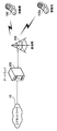
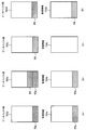
- FIG. 1 is a diagram illustrating a wireless communication system according to the first embodiment.
- the wireless communication system according to the first embodiment includes a wireless communication device 1 and a wireless communication device 2.
- the wireless communication device 2 reserves transmission resources 2b1 and 2b2 in advance for the wireless communication device 1 and dynamically allocates them when requested by the wireless communication device 1.
- Transmission resource 2c1 to be set can be set.
- the transmission resources 2b1 and 2b2 are regular transmission resources at regular intervals, for example.
- transmission resources 2b1 and 2b2 are referred to as first transmission resources or rule transmission resources
- transmission resources 2c1 are referred to as second transmission resources or dynamic transmission resources.
- the wireless communication device 1 can transmit data to the wireless communication device 2 using the first transmission resources 2b1, 2b2 and the second transmission resource 2c1 set by the wireless communication device 2.
- the wireless communication system according to the first embodiment may be capable of transmitting data from the wireless communication device 2 to the wireless communication device 1.
- the wireless communication device 1 may be a mobile station, a fixed station, or a relay station. Further, the wireless communication device 2 may be a relay station or a base station.
- the wireless communication device 1 has a control unit 1a.
- the control unit 1a transmits the data amount (for example, the size of the packet 1b to be transmitted) according to the data stored in the buffer of the own device and the data amount (for example, the packet 1b) that can be transmitted by the first transmission resource. Comparison is made with the size of the packet that can be transmitted by the first transmission resource 2b2.
- the control unit 1a controls the request for setting the second transmission resource 2c1 for the wireless communication device 2 according to the comparison result.
- the wireless communication device 1 if the size of the packet 1b to be transmitted is equal to or smaller than the size of the packet that can be transmitted by the first transmission resource 2b2 that has already been reserved, the reserved first The packet 1b can be transmitted using only the transmission resource 2b2.
- the wireless communication device 1 requests the setting of the second transmission resource 2c1, and when the second transmission resource 2c1 is set by the wireless communication device 2 accordingly, the packet 1b is transmitted by the second transmission resource 2c1 without waiting for the timing of the first transmission resource 2b2. That is, there is a possibility that the first transmission resource 2b2 that has already been reserved is not used and is wasted. Therefore, the control unit 1a controls the setting request of the second transmission resource 2c1 according to the comparison result, thereby suppressing the useless setting request of the second transmission resource 2c1.
- the control unit 1a determines that the amount of data (the size of the packet 1b to be transmitted) corresponding to the data stored in the buffer of its own device is less than the amount of data (the size of the packet) that can be transmitted by the first transmission resource 2b2. If it is, the wireless communication device 2 is not requested to set the second transmission resource 2c1. As a result of the comparison, the control unit 1a determines that the amount of data (the size of the packet 1b to be transmitted) corresponding to the data stored in the buffer of its own device is less than the amount of data (the size of the packet) that can be transmitted by the first transmission resource 2b2.
- the resource request for requesting the setting of the second transmission resource 2c1 for the wireless communication device 2 may not be transmitted.
- the resource request may be, for example, a BSR that reports the amount of buffer data stored in a buffer (not shown) included in the wireless communication device 1 to the wireless communication device 2.
- control unit 1a may control transmission of a resource request including information indicating that setting of the second transmission resource 2c1 for the wireless communication device 2 is unnecessary according to the comparison result.
- the data amount (size of the packet 1b to be transmitted) corresponding to the data stored in the buffer of the own device is equal to or less than the data amount (packet size) that can be transmitted by the first transmission resource 2b2.
- a resource request including information indicating that setting of the second transmission resource 2c1 is unnecessary may be transmitted.
- the information indicating that it is not necessary to set the second transmission resource 2c1 may be buffer data amount information indicating that the buffer data amount is equal to or less than a predetermined threshold (for example, “0 bytes”).
- the predetermined threshold value is not limited to “0 Byte”, and an arbitrary positive value may be set.
- control unit 1a determines whether or not the data stored in the buffer is only real-time data such as VoIP data and moving image data, and requests for setting the second transmission resource according to the determination result. May be controlled.
- the wireless communication device 2 has a resource setting unit 2a.
- the resource setting unit 2a sets the second transmission resource 2c1 for the wireless communication device 1 in accordance with the control of the setting request for the second transmission resource 2c1 according to the comparison result transmitted from the wireless communication device 1. Control.
- the resource setting unit 2a dynamically activates the wireless communication apparatus 1 when the buffer data amount indicated by the buffer data amount information included in the resource request is equal to or less than a predetermined threshold (for example, “0 Byte”). It is not necessary to set transmission resources.
- the wireless communication system can suppress generation of useless DS resources by suppressing requests for setting useless dynamic transmission resources, and can suppress a decrease in resource utilization efficiency. .
- it is preferable to divide the packet 1b, by making a request for setting the second transmission resource 2c1 it is possible to suppress the occurrence of subsequent packet division while suppressing a decrease in resource utilization efficiency. It is possible to suppress an increase in the burden on the wireless communication apparatuses 1 and 2 due to an increase in division.
- the wireless communication system according to the first embodiment can be implemented as an LTE system.
- the radio communication system according to the first embodiment can be realized as, for example, LTE A (LTE Advanced), another type of mobile communication system, or a fixed radio communication system.
- LTE A LTE Advanced
- another type of mobile communication system or a fixed radio communication system.
- FIG. 2 is a diagram illustrating a wireless communication system according to the second embodiment.
- the wireless communication system according to the second embodiment includes a mobile station 100, a mobile station 100a, a plurality of base stations including the base station 200, and a gateway 300.
- the mobile station 100 is an example of the wireless communication device 1.
- the base station 200 is an example of the wireless communication device 2.
- the mobile stations 100 and 100a are wireless terminal devices that perform wireless communication with the base station 200, for example, mobile phones and portable information terminal devices.
- the mobile stations 100 and 100a transmit user data to the base station 200 on the uplink (UL) and receive user data from the base station 200 on the downlink (DL: DownLink).
- UL uplink
- DL Downlink
- the base station 200 is a wireless communication device that performs wireless communication with the mobile stations 100 and 100a.
- Base station 200 is connected to gateway 300 via a wired network.
- the base station 200 transfers user data of the mobile station 100 between the mobile station 100 and the gateway 300, and transfers user data of the mobile station 100a between the mobile station 100a and the gateway 300.
- the gateway 300 is an example of a host device connected to the core network 10 and is a communication device that processes user data of the mobile stations 100 and 100a.
- the gateway 300 transmits user data transmitted from the mobile stations 100 and 100 a via the base station 200 to the core network 10. Further, the gateway 300 performs a process of transmitting user data addressed to the mobile stations 100 and 100a transmitted from the core network 10 to each of the mobile stations 100 and 100a via the base station 200. Accordingly, the mobile stations 100 and 100a can communicate with other mobile stations and other terminal devices via the core network 10.
- LTE wireless communication is performed between the mobile station 100 and the base station 200.
- the present invention is not limited to this, and communication may be performed using another wireless communication method such as LTE A, in which wireless communication is performed using SPS resources and DS resources.
- the mobile station 100 is an example of the wireless communication device 1
- the base station 200 is an example of the wireless communication device 2.
- the wireless communication device 1 may be a wireless communication relay station. In this case, wireless communication is performed using the wireless communication device 2 as a base station. Further, the wireless communication device 2 may be a relay station. In this case, wireless communication is performed using the wireless communication device 1 as a mobile station.
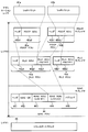
- FIG. 3 is a diagram illustrating a hardware configuration of the mobile station according to the second embodiment.
- the mobile station 100 according to the second embodiment includes a CPU (Central Processing Unit) 101, a data buffer unit 102, a speaker 103, a microphone 104, a monitor 105, a layer 1 unit 110, and an application unit 141.
- CPU Central Processing Unit
- the CPU 101 mainly performs layer 2 and layer 3 communication processing in the mobile station 100 and controls layer 1 communication performed by the layer 1 unit 110.
- the CPU 101 outputs data transmitted from the base station 200 stored in the data buffer unit 102 to the application unit 141.
- the CPU 101 causes the data buffer unit 102 to store data transmitted from the application unit 141 and transmitted to the base station 200.
- the CPU 101 reads a program and data from a ROM (Read Only Memory) (not shown), develops it in a RAM (Random Access Memory) (not shown), and executes the program.
- the RAM is a volatile memory that temporarily stores at least part of programs and data. Note that other types of memory may be used instead of the RAM.
- the ROM is a non-volatile memory that stores programs and data used by the CPU 101. Note that a nonvolatile memory such as a flash memory may be used instead of the ROM.
- the control performed by the CPU 101 includes call connection control and the like in addition to data control.
- the data buffer unit 102 is a buffer memory that temporarily stores data transmitted from the mobile station 100 and data received by the mobile station 100 for adjustment of transmission / reception timing.
- the data buffer unit 102 can be realized by, for example, a RAM such as SRAM (Static RAM) or other storage device.
- Speaker 103 reproduces sound by converting an electrical signal into physical vibration under the control of CPU 141a.
- the voice of the other party or the background noise of the other party is output from the speaker 103.
- the microphone 104 converts the physical vibration of sound into an electrical signal, receives a voice input, and outputs it to the data buffer unit 102 according to the control of the CPU 141a.
- the voice of the user or background noise on the user side is input from the microphone 104.
- the monitor 105 performs various notifications to the user by displaying various images according to the control of the CPU 141a.
- a liquid crystal display (LCD), an organic EL (Electro Luminescence) display, or the like can be used.
- the image displayed on the monitor 105 includes a standby screen, an operation screen, text, a content image, and the like.
- the layer 1 unit 110 executes layer 1 communication processing on data transmitted from the mobile station 100 and data received by the mobile station 100.
- the layer 1 unit 110 includes a DSP (Digital Signal Processor) 110a, a wireless communication unit 110b, a modulation / demodulation unit 110c, and an encoding / decoding unit 110d.
- DSP Digital Signal Processor
- the DSP 110a is a microprocessor that performs digital signal processing by controlling the modulation / demodulation unit 110c and the encoding / decoding unit 110d in the mobile station 100.
- the wireless communication unit 110b performs wireless communication with the base station 200 using LTE.
- the radio communication unit 110b converts a radio signal received by the antenna into a baseband signal and outputs the baseband signal to the modulation / demodulation unit 110c.
- the wireless communication unit 110b converts the baseband signal output from the modulation / demodulation unit 110c into a wireless signal and transmits it from the antenna.
- the wireless communication unit 110b may communicate with another mobile communication such as LTE A.
- the modulation / demodulation unit 110c When the modulation / demodulation unit 110c acquires the signal encoded by the encoding / decoding unit 110d according to the control of the DSP 110a, the modulation / demodulation unit 110c modulates and outputs the signal to the wireless communication unit 110b. Further, when the modulation / demodulation unit 110c acquires a baseband signal from the wireless communication unit 110b in accordance with the control of the DSP 110a, the modulation / demodulation unit 110c demodulates and transmits it to the encoding / decoding unit 110d.
- the encoding / decoding unit 110d When the encoding / decoding unit 110d acquires the data to be transmitted stored in the data buffer unit 102 according to the control of the DSP 110a, the encoding / decoding unit 110d performs error correction encoding and outputs the data to the modulation / demodulation unit 110c. In addition, when the encoding / decoding unit 110d acquires the demodulated signal from the modulation / demodulation unit 110c according to the control of the DSP 110a, the encoding / decoding unit 110d performs error correction decoding and stores the signal in the data buffer unit 102.
- the wireless communication unit 110b performs wireless signal processing.
- the present invention is not limited to this, and the DSP 110a may perform part of the wireless signal processing.
- the application unit 141 executes application layer processing in communication of data transmitted from the mobile station 100 and data received by the mobile station 100.
- the application unit 141 includes a CPU 141a, an audio processing unit 141b, and a video processing unit 141c.
- the CPU 141a mainly controls communication in the application layer in the mobile station 100.
- the CPU 141a reads a program and data from a ROM (not shown), develops it in a RAM (not shown), and executes the program.
- a ROM not shown
- RAM not shown
- other types of memory may be used instead of the RAM.
- a nonvolatile memory such as a flash memory may be used instead of the ROM.
- the control performed by the CPU 141a includes voice input / output control, video control, operation input control, and the like.
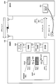
- FIG. 4 is a diagram illustrating a hardware configuration of the base station according to the second embodiment.
- the base station 200 according to the second embodiment includes a CPU 201, a data buffer unit 202, and a layer 1 unit 210, and is connected to the gateway 300 by wired communication.
- the CPU 201 performs layer 2 and layer 3 communication processing and controls the entire base station such as layer 1 communication.
- the CPU 201 outputs the data transmitted from the mobile station 100 stored in the data buffer unit 202 to the gateway 300. Further, the CPU 201 causes the data buffer unit 202 to store data transmitted from the gateway 300 to the mobile station 100.
- the CPU 201 reads a program and data from a ROM (not shown), develops it in a RAM (not shown), and executes the program.
- the RAM is a volatile memory that temporarily stores at least part of programs and data. Note that other types of memory may be used instead of the RAM.
- the ROM is a non-volatile memory that stores programs and data used by the CPU 201. Note that a nonvolatile memory such as a flash memory may be used instead of the ROM.
- the processing performed by the CPU 201 includes, in addition to data processing, management of user connection status, resource setting scheduling, confidential processing, and the like.
- the data buffer unit 202 is a buffer memory that temporarily stores data transmitted from the base station 200 and data received by the base station 200 in order to adjust transmission / reception timing. Data transmitted and received by the base station 200 is transferred to and from the gateway 300 via the data buffer unit 202.
- the data buffer unit 202 can be realized by, for example, a RAM such as an SRAM or another storage device.
- the layer 1 unit 210 performs layer 1 communication processing on data transmitted from the base station 200 and data received by the base station 200 according to the control of the CPU 201.
- the layer 1 unit 210 includes a wireless communication unit 210b, a modulation / demodulation unit 210c, and an encoding / decoding unit 210d.
- the wireless communication unit 210b performs wireless communication with the mobile station 100 using LTE.
- the radio communication unit 210b converts the radio signal received by the antenna into a modulation / demodulation unit 210c into a baseband signal and outputs the baseband signal.
- the wireless communication unit 210b converts the baseband signal output from the modulation / demodulation unit 210c into a wireless signal and transmits it from the antenna. Note that the wireless communication unit 210b may communicate with another mobile communication such as LTE A.
- the modulation / demodulation unit 210c When the modulation / demodulation unit 210c acquires the signal encoded by the encoding / decoding unit 210d according to the control of the CPU 201, the modulation / demodulation unit 210c modulates and outputs the modulated signal to the wireless communication unit 210b. Also, when the modulation / demodulation unit 210c acquires a baseband signal from the wireless communication unit 210b according to the control of the CPU 201, the modulation / demodulation unit 210c demodulates and transmits it to the encoding / decoding unit 210d.
- the encoding / decoding unit 210d When the encoding / decoding unit 210d acquires the data to be transmitted stored in the data buffer unit 202 according to the control of the CPU 201, the encoding / decoding unit 210d performs error correction encoding and outputs the data to the wireless communication unit 210b. Also, when the encoding / decoding unit 210d acquires the demodulated signal from the modulation / demodulation unit 210c under the control of the CPU 201, the encoding / decoding unit 210d performs error correction decoding and stores the signal in the data buffer unit 202.
- the CPU 201 performs layer 2 and layer 3 processing, and the layer 1 unit 210 performs layer 1 processing.
- the present invention is not limited to this.
- One processor may do.
- hardware that performs a part of processing (for example, confidential processing) among processing performed by the CPU 201 such as layer 2 processing, or hardware that supports part of the processing may be provided.
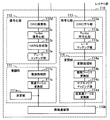
- FIG. 5 is a diagram illustrating communication processing of the mobile station according to the second embodiment.
- the mobile station 100 according to the second embodiment includes a layer 1 unit 110, a layer 2 unit 120, a radio resource control unit 131, and an application unit 141, and each unit controls communication processing and communication processing.
- the layer 1 unit 110 includes a wireless communication unit 110b, a demodulation unit 111, a decoding unit 112, an encoding unit 113, and a modulation unit 114, and each unit controls layer 1 communication processing and communication processing.
- the layer 1 unit 110 is realized by the DSP 110a, the wireless communication unit 110b, the modulation / demodulation unit 110c, and the encoding / decoding unit 110d described above.
- the radio communication unit 110b converts the high-frequency signal received by the antenna into a baseband signal and outputs the baseband signal to the demodulation unit 111, and converts the baseband signal output from the modulation / demodulation unit 110c into a high-frequency signal and transmits it from the antenna. .
- the demodulator 111 When the demodulator 111 acquires the baseband signal from the radio communication unit 110 b, the demodulator 111 performs demodulation processing using an OFDMA (Orthogonal Frequency Division Multiple Access) scheme and transmits the demodulated signal to the decoding unit 112.
- OFDMA Orthogonal Frequency Division Multiple Access
- Decoding section 112 performs error correction decoding on the data received at mobile station 100 and outputs the data to layer 2 section 120.
- Encoding section 113 performs error correction encoding on the data transmitted from mobile station 100 and outputs the result to radio communication section 110b.
- the Modulation section 114 performs modulation processing by SC-FDMA (Single Carrier Frequency Division Multiple Access: Single Carrier-FDMA) and outputs the result to radio communication section 110b.
- the layer 2 unit 120 includes a MAC (Media Access Control) receiver 121, an RLC (Radio Link Control) receiver 122, a PDCP (Packet Data Convergence Protocol) receiver 123, a PDCP transmitter 124, an RLC transmitter 125, and a MAC transmitter. 126.
- Each unit of the layer 2 unit 120 performs layer 2 communication processing and communication processing control.
- the layer 2 unit 120 has three sub-layers: a MAC sublayer, an RLC sublayer, and a PDCP sublayer.
- the layer 2 unit 120 separates and combines data according to the format of each sublayer.
- the layer 2 unit 120 is realized by the CPU 101 and the data buffer unit 102 described above.
- the MAC receiving unit 121 separates data received by the mobile station 100 for each logical channel (LCH: Logical Channel), analyzes the MAC CE (Control Element) included in the received data, and analyzes the analysis result in layer 1 Feedback to the unit 110 and the MAC transmission unit 126.
- LCH Logical Channel
- the RLC receiver 122 separates and combines data according to the MAC and PDCP formats. In addition, the RLC reception unit 122 performs a process (reordering process) for correcting a change in the reception order of data generated due to an error in wireless communication.
- the PDCP receiving unit 123 transfers the data acquired from the RLC receiving unit 122 to the radio resource control unit 131 and the application unit 141 in the order of sequence numbers.
- the PDCP transmission unit 124 sets a sequence number in the data acquired from the radio resource control unit 131 and the application unit 141 and transfers the data to the RLC transmission unit 125.
- the RLC transmission unit 125 separates and combines data in accordance with each format of MAC and PDCP.
- the RLC transmission unit 125 performs retransmission control (ARQ: Automatic Repeat request).
- the MAC transmission unit 126 multiplexes the data of each logical channel and the MAC CE to generate a MAC PDU (Protocol Data Unit) of data transmitted from the mobile station 100. Further, the MAC transmission unit 126 manages the buffer data amount stored in the data buffer unit 102, generates a surplus transmission power value, determines the transmission data amount for each logical channel based on the logical channel priority, and HARQ. (Hybrid ARQ) Control processing is performed.
- MAC PDU Protocol Data Unit
- the radio resource control unit 131 controls radio resources and the entire radio communication in the mobile station 100.
- the radio resource control unit 131 performs processes such as paging, call establishment and release, communication state measurement, management and reporting, connection switching control such as handover and reselection.
- the application unit 141 is a higher layer that processes user data received by the mobile station 100 and generates user data transmitted from the mobile station 100.
- the mobile station 100 according to the second embodiment transmits data to the base station 200 after performing modulation using the SC-FDMA scheme in uplink communication.
- the present invention is not limited to this, and other communication methods that can be used for uplink communication may be used.
- the mobile station 100 receives data transmitted from the base station 200 in downlink communication, the mobile station 100 demodulates the data using the OFDMA scheme.
- the present invention is not limited to this, and other communication methods that can be used for downlink communication, such as the SOFDA (Scalable OFDMA) method, may be used.
- FIG. 6 is a diagram illustrating layer 1 communication processing of the mobile station according to the second embodiment.
- the layer 1 unit 110 of the mobile station 100 according to the second embodiment includes the radio communication unit 110b, the demodulation unit 111, the decoding unit 112, the encoding unit 113, and the modulation unit 114. Layer 1 communication processing and control of communication processing are performed.
- the wireless communication unit 110b mutually converts the wireless signal and the baseband signal.
- the demodulator 111 acquires the baseband signal from the wireless communication unit 110b, the demodulator 111 performs demodulation processing and transmits the demodulated signal to the decoder 112.
- the demodulation unit 111 includes a measurement unit 111a, a fast Fourier transform unit 111b, and a demodulation processing unit 111c.
- the measurement unit 111a performs cell search and level measurement.
- the fast Fourier transform unit 111b demodulates the OFDMA symbol by FFT (Fast Fourier Transform).
- the demodulation processing unit 111c demodulates the multi-level modulated symbol by QPSK (Quadrature Phase Shift Keying), 16QAM (Quadrature Amplitude Modulation), 64QAM, or the like.
- Decoding section 112 performs error correction decoding on the data received at mobile station 100 demodulated by demodulation section 111 and outputs the data to layer 2 section 120 as described above.
- the decoding unit 112 includes a derate matching unit 112a, a HARQ combining unit 112b, a Turbo decoding unit 112c, and a CRC (Cyclic Redundancy Check) checking unit 112d.
- the derate matching unit 112a restores data that has been expanded or reduced in accordance with the set physical channel resource.
- the HARQ combining unit 112b combines retransmission data by HARQ retransmission processing.
- the Turbo decoding unit 112c decodes the Turbo encoded data.
- the CRC checking unit 112d checks the correctness of the decoded data by CRC.
- the encoding unit 113 performs error correction encoding on the data acquired from the layer 2 unit 120 and transmitted from the mobile station 100 and outputs the data to the modulation unit 114.
- the encoding unit 113 includes a CRC adding unit 113a, a Turbo encoding unit 113b, and a rate matching unit 113c.
- the CRC assigning unit 113a calculates a CRC for the data acquired from the layer 2 unit 120 and assigns a calculation result.
- the Turbo encoding unit 113b performs Turbo encoding of the data to which the CRC is added by the CRC adding unit 113a.
- the rate matching unit 113c decompresses or reduces data according to the set physical channel resource.
- the modulation unit 114 performs modulation processing by the SC-FDMA scheme on the data transmitted from the mobile station 100 encoded by the encoding unit 113 and outputs the data to the radio communication unit 110b.
- the modulation unit 114 includes a modulation processing unit 114a, a discrete Fourier transform unit 114b, a subcarrier mapping unit 114c, and an inverse fast Fourier transform unit 114d.
- the modulation processing unit 114a performs multilevel modulation using QPSK, 16QAM, 64QAM, or the like.
- the discrete Fourier transform unit 114b performs DFT (Discrete Fourier Transform) processing in order to perform SC-FDMA modulation.
- DFT Discrete Fourier Transform
- the subcarrier mapping unit 114c performs processing for setting data transmitted from the mobile station 100 to a physical channel resource designated from the network.
- the inverse fast Fourier transform unit 114d modulates data transmitted from the mobile station 100 into SC-FDMA symbols by IFFT (Inverse Fast Fourier Transform: Inverse FFT).
- FIG. 7 is a diagram illustrating layer 2 communication processing of the mobile station according to the second embodiment.
- the layer 2 unit 120 of the mobile station 100 according to the second embodiment includes the MAC reception unit 121, the RLC reception unit 122, the PDCP reception unit 123, the PDCP transmission unit 124, the RLC transmission unit 125, and the MAC transmission unit. 126.
- Each unit of the layer 2 unit 120 performs layer 2 communication processing and communication processing control.
- the MAC reception unit 121 includes an LCH separation unit 121a and a MAC CE analysis unit 121b.
- the LCH separator 121a separates the data received from the layer 1 unit 110 and received by the mobile station 100 for each logical channel.
- the MAC CE analysis unit 121b analyzes the MAC CE included in the received data, and feeds back the analysis result to the layer 1 unit 110 and the MAC transmission unit 126.
- the RLC reception unit 122 transfers the data acquired from the MAC reception unit 121 to the PDCP reception unit 123 as described above. In addition, the RLC reception unit 122 performs reordering processing of received data.
- the PDCP reception unit 123 transfers the data acquired from the RLC reception unit 122 to the radio resource control unit 131 and the application unit 141.
- the PDCP transmission unit 124 transfers the data acquired from the radio resource control unit 131 and the application unit 141 to the RLC transmission unit 125.
- the RLC transmission unit 125 transfers the data acquired from the PDCP transmission unit 124 to the MAC transmission unit 126.
- the RLC transmission unit 125 performs retransmission control.
- the MAC transmission unit 126 includes a BSR unit 126a, a PHR (Power HeadRoom) unit 126b, an LCH priority processing unit 126c, an UL (UpLoad) -HARQ unit 126d, and a MAC PDU generation unit 126e.
- the BSR unit 126 a manages the buffer data amount stored in the data buffer unit 102.
- the PHR unit 126b generates a surplus transmission power value.
- the LCH priority processing unit 126c determines the transmission data amount for each logical channel according to the priority of the logical channel.
- the UL-HARQ unit 126d performs HARQ control of data transmitted from the mobile station 100.
- the MAC PDU generation unit 126e generates a MAC PDU transmitted from the mobile station 100 by multiplexing the data of each logical channel and the MAC CE.
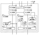
- FIG. 8 is a diagram illustrating communication processing of the base station according to the second embodiment.
- the base station 200 according to the second embodiment includes a layer 1 unit 210, a layer 2 unit 220, and a radio resource control unit 231, and each unit controls communication processing and communication processing.
- the layer 1 unit 210 includes a wireless communication unit 210b, a demodulation unit 211, a decoding unit 212, an encoding unit 213, and a modulation unit 214, and each unit controls layer 1 communication processing and communication processing.
- Data processing in the layer 1 unit 210 is performed in the same manner as the mobile station 100. However, in the base station 200, as will be described in detail later, data for each user is multiplexed immediately before transmission of physical channel data (before IFFT) and immediately after reception of physical channel data (after FFT). ), User separation is performed. The data of each user is encoded and modulated, demodulated and decoded on a user basis.
- the layer 1 unit 210 is realized by the CPU 201, the wireless communication unit 210b, the modulation / demodulation unit 210c, and the encoding / decoding unit 210d described above.
- the radio communication unit 210b converts a high-frequency signal received by the antenna into a baseband signal and outputs the baseband signal to the demodulation unit 211, and converts the baseband signal output from the modulation / demodulation unit 210c into a high-frequency signal and transmits it from the antenna. .
- the demodulation unit 211 When acquiring the baseband signal from the radio communication unit 210b, the demodulation unit 211 performs demodulation processing by the SC-FDMA method and transmits the demodulation processing to the decoding unit 212.
- Decoding section 212 performs error correction decoding on the data received at base station 200 and outputs the data to layer 2 section 220.
- the encoding unit 213 performs error correction encoding on the data transmitted from the base station 200 and outputs the data to the wireless communication unit 210b.
- the modulation unit 214 performs modulation processing by the OFDMA method and outputs the result to the wireless communication unit 210b.
- the layer 2 unit 220 includes a MAC reception unit 221, an RLC reception unit 222, a PDCP reception unit 223, a PDCP transmission unit 224, an RLC transmission unit 225, and a MAC transmission unit 226. Each unit performs layer 2 communication processing and communication processing. Control.
- the layer 2 unit 220 includes three sublayers, a MAC sublayer, an RLC sublayer, and a PDCP sublayer, and performs data separation and combination in accordance with the format of each sublayer. The processing of the layer 2 unit 220 is also performed for each user, as in the layer 1 unit 210, as will be described in detail later.
- the layer 2 unit 220 is realized by the CPU 201 and the data buffer unit 202 described above.
- the MAC receiving unit 221 separates the data received at the base station 200 for each logical channel, analyzes the MAC CE included in the received data, and feeds back the analysis result to the MAC transmitting unit 226.
- the RLC receiver 222 separates and combines data according to the MAC and PDCP formats. In addition, the RLC reception unit 222 performs reordering processing of received data.
- the PDCP receiving unit 223 transfers the data acquired from the RLC receiving unit 222 to the radio resource control unit 231 and the gateway 300 in the order of sequence numbers.
- the PDCP transmission unit 224 sets a sequence number in the data acquired from the radio resource control unit 231 and the gateway 300 and transfers the sequence number to the RLC transmission unit 225.
- the RLC transmission unit 225 separates and combines data in accordance with the MAC and PDCP formats. In addition, the RLC transmission unit 225 performs retransmission control.
- the MAC transmission unit 226 generates data to be transmitted from the base station 200 by multiplexing data of each logical channel and MAC CE. Further, the MAC transmission unit 226 performs processing such as determination of the transmission data amount for each logical channel based on the priority of the logical channel, HARQ control, and the like.
- the radio resource control unit 231 controls radio resources and the entire radio communication in the base station 200.
- the radio resource control unit 231 performs processing such as connection switching control such as paging, call establishment and release, handover, and reselection.
- the radio resource control unit 231 is connected to the gateway 300 and transmits / receives data to / from the core network 10.
- the gateway 300 is connected to the base station 200 by wired communication, performs processing for transmitting user data received by the base station 200 to the core network 10, and transmits a user data from the base station 200 to the core network 10. Device.
- the base station 200 modulates the data using the OFDMA scheme in downlink communication and transmits data to the mobile station 100.
- the present invention is not limited to this, and other communication methods that can be used for downlink communication such as the SOFDA method may be used.
- the base station 200 demodulates using the SC-FDMA scheme.
- the present invention is not limited to this, and other communication methods that can be used for uplink communication may be used.
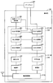
- FIG. 9 is a diagram illustrating layer 1 communication processing of the base station according to the second embodiment.
- the layer 1 unit 210 of the base station 200 according to the second embodiment includes the radio communication unit 210b, the demodulation unit 211, the decoding unit 212, the encoding unit 213, and the modulation unit 214. Layer 1 communication processing and control of communication processing are performed.
- the wireless communication unit 210b mutually converts the wireless signal and the baseband signal.
- the demodulator 211 acquires the baseband signal from the wireless communication unit 210b
- the demodulator 211 performs demodulation processing and transmits the demodulated signal to the decoder 212.
- the demodulation unit 211 includes a fast Fourier transform unit 211b and a subcarrier demapping unit 211d that collectively process data multiplexed for a plurality of users. Further, the demodulation unit 211 includes a demodulation processing unit 211c and an inverse discrete Fourier transform unit 211e provided for each user (for example, user 1, user 2,).
- the fast Fourier transform unit 211b demodulates the SC-FDMA symbol by FFT.
- the subcarrier demapping unit 211d extracts data received at the base station 200 from the physical channel resource of the signal demodulated by the fast Fourier transform unit 211b.
- the demodulation processing unit 211c demodulates the symbols that are multi-level modulated by QPSK, 16QAM, 64QAM, or the like.
- the decoding unit 212 performs error correction decoding on the data received at the base station 200 demodulated for each user by the demodulation unit 211 and outputs the data to the layer 2 unit 220 for each user.
- the decoding unit 212 includes a derate matching unit 212a, a HARQ combining unit 212b, a Turbo decoding unit 212c, and a CRC checking unit 212d.
- the derate matching unit 212a restores data that has been expanded or reduced in accordance with the set physical channel resource.
- the HARQ combining unit 212b combines retransmission data by HARQ retransmission processing.
- the Turbo decoding unit 212c decodes the Turbo encoded data.
- the CRC checker 212d checks the correctness of the decoded data by CRC.
- the encoding unit 213 performs error correction encoding on the data transmitted from the base station 200 acquired for each user from the layer 2 unit 220 and outputs the data to the modulation unit 214 for each user.
- the encoding unit 213 includes a CRC adding unit 213a, a Turbo encoding unit 213b, and a rate matching unit 213c.
- the CRC assigning unit 213a calculates a CRC for the data acquired from the layer 2 unit 220 and assigns a calculation result.
- the Turbo encoding unit 213b performs Turbo encoding of the data to which the CRC is added by the CRC adding unit 213a.
- the rate matching unit 213c decompresses or reduces data according to the set physical channel resource.
- the modulation unit 214 performs modulation processing by the OFDMA method on the data transmitted from the base station 200 encoded by the encoding unit 213 for each user, and multiplexes the data for each user to perform wireless communication.
- the modulation unit 214 includes a modulation processing unit 214a and a subcarrier mapping unit 214c provided for each user.
- the modulation unit 214 includes an inverse fast Fourier transform unit 214d that performs batch processing on data multiplexed for a plurality of users.
- the modulation processing unit 214a performs multi-level modulation using QPSK, 16QAM, 64QAM, or the like.
- the subcarrier mapping unit 214c performs processing for setting data transmitted from the base station 200 to a physical channel resource designated from the network.
- the inverse fast Fourier transform unit 214d multiplexes the data for each user transmitted from the base station 200 and modulates the data into OFDMA symbols by IFFT.
- FIG. 10 is a diagram illustrating layer 2 communication processing of the base station according to the second embodiment.
- the layer 2 unit 220 of the base station 200 according to the second embodiment includes the MAC reception unit 221, the RLC reception unit 222, the PDCP reception unit 223, the PDCP transmission unit 224, the RLC transmission unit 225, and the MAC transmission unit. 226.
- Each unit of the layer 2 unit 220 controls communication processing of layer 2 and communication processing.
- the processing of the layer 2 unit 220 is performed for each user as the entire layer 2 unit 220. That is, when the layer 2 unit 220 performs the process of the user 1, the processes of other users (users 2,...) Are performed by different layer 2 units that are different for each user. In the process of the layer 2 unit 220, scheduling between users is also performed.
- the MAC reception unit 221 includes an LCH separation unit 221a and a MAC CE analysis unit 221b.
- the LCH separation unit 221a separates the data received from the layer 1 unit 210 and received by the base station 200 for each logical channel.
- the MAC CE analysis unit 221b analyzes the MAC CE included in the received data and feeds back the analysis result to the MAC transmission unit 226.
- the RLC receiver 222 transfers the data acquired from the MAC receiver 221 to the PDCP receiver 223 as described above. In addition, the RLC reception unit 222 performs reordering processing of received data.
- the PDCP receiver 223 transfers the control data acquired from the RLC receiver 222 to the radio resource controller 231 and transfers the user data acquired from the RLC receiver 222 to the gateway 300.
- the PDCP transmission unit 224 transfers the control data acquired from the radio resource control unit 231 and the user data acquired from the gateway 300 to the RLC transmission unit 225.
- the RLC transmission unit 225 transfers the data acquired from the PDCP transmission unit 224 to the MAC transmission unit 226 as described above. In addition, the RLC transmission unit 225 performs retransmission control.
- the MAC transmission unit 226 includes an LCH priority processing unit 226c, a UL-HARQ unit 226d, and a MAC PDU generation unit 226e.
- the LCH priority processing unit 226c determines the transmission data amount for each logical channel according to the priority of the logical channel.
- the UL-HARQ unit 226d performs HARQ control of data transmitted from the base station 200.
- the MAC PDU generation unit 226e generates a MAC PDU transmitted from the base station 200 by multiplexing the data of each logical channel and the MAC CE.
- FIG. 11 is a diagram illustrating a processing example of the layer 2 data according to the second embodiment.
- the following processing is performed.
- FIG. 11 when VoIP packets 41a and 41b are transmitted by LCH # 2, and control data and user data of other services are transmitted by another logical channel (for example, LCH # 1). This will be explained based on.
- the PDCP sublayer of the layer 2 unit 120 sequentially receives the VoIP packets 41a and 41b from the application layer by LCH # 2.
- the PDCP sublayer acquires the received VoIP packets 41a and 41b as PDCP SDU (Service Data Unit) 42a2 and 42b2, respectively.
- the PDCP sublayer generates PDCP PDUs 42a and 42b by adding headers 42a1 and 42b1 including sequence numbers to the acquired PDCP SDUs 42a2 and 42b2, and transfers them to the RLC sublayer.
- the RLC sublayer of the layer 2 unit 120 acquires the PDCP PDUs 42a and 42b as RLC SDUs, respectively.
- the RLC sublayer independently generates the RLC PDU by adding a header without dividing, combining, or performing the obtained RLC SDU, and transfers the RLC PDU to the MAC sublayer.
- the RLC sublayer does not divide the PDCP PDU 42 a and uses the RLC SDU 43 a 2.
- the RLC sublayer can be divided into RLC SDU segments 43a3 and 43b2 after acquiring the PDCP PDU 42b as the RLC SDU.
- the RLC sublayer combines the RLC SDU 43a2 and the RLC SDU segment 43a3 to adjust the size, and adds the header 43a1 to generate the RLC PDU 43a.
- the RLC sublayer transfers the generated RLC PDU 43a to the MAC sublayer.
- the RLC sublayer generates the RLC PDU 43b by adding the header 43b1 to the divided RLC SDU segment 43b2, and transfers it to the MAC sublayer.
- the processes in the PDCP sublayer and the RLC sublayer described above are performed for each logical channel.
- the MAC sublayer of the layer 2 unit 120 acquires the RLC PDU 43a generated for the LCH # 2 as the MAC SDU 444.
- the MAC sublayer combines the acquired MAC SDU 444, the MAC SDU 443 generated for other logical channels, and the generated MAC CE 442, and adds a header 441 to generate a MAC PDU 44.
- the MAC sublayer adjusts the size of the MAC PDU 44 by adding a padding 445 when the size of data to be transmitted is insufficient with respect to the size that can be transmitted in the generated MAC PDU 44.
- the layer 1 unit 110 of the mobile station 100 acquires the MAC PDU 44 generated in the MAC sublayer and transmits the MAC PDU 44 as the transport block 45 to the base station 200.
- the VoIP packets 41a and 41b are illustrated and described.
- the present invention is not limited to this, and the second embodiment is not limited to other audio data such as music distribution, real-time data such as moving image data, and the like. It can also be applied when transmitting user data.
- FIG. 12 is a block diagram illustrating a wireless communication system according to the second embodiment.
- the wireless communication system according to the second embodiment includes a mobile station 100 and a base station 200.
- the radio communication system according to the second embodiment can transmit and receive user data such as VoIP data and control data for controlling transmission and reception of user data between the mobile station 100 and the base station 200.
- the base station 200 can set the SPS resources 261 and 262 at regular intervals and the DS resource 271 according to the request of the mobile station 100 for the mobile station 100.
- the mobile station 100 can transmit data to the base station 200 using the SPS resources 261 and 262 and the DS resource 271 set from the base station 200.
- the SPS resources 261 and 262 are examples of first transmission resources (rule transmission resources) for which allocation is reserved in advance.
- the DS resource 271 is an example of a second transmission resource (dynamic transmission resource).
- the SPS resources 261 and 262 are set in a cycle in which a period obtained by adding or subtracting a SPS cycle to a reference cycle (eg, 20 ms) at a specified time (eg, 5 ms) alternately.
- a reference cycle eg, 20 ms
- a specified time eg, 5 ms
- a long period for example, 25 ms obtained by adding a specified time to the reference period and a short period (15 ms) are alternately set.
- the VoIP data can be generated periodically, and the voice encoding interval at which the VoIP data can be generated is set shorter (for example, 20 ms) than the long cycle.
- the reference period is an element that determines the setting interval of the SPS resource.
- the reference period is usually set based on the voice encoding period of the VoIP packet so that the amount of data that can be transmitted by the SPS resource for a certain period is equal to or greater than the data amount of the generated VoIP packet. .
- the reference period may be set equal to or close to the speech coding period.
- the above-described reference period of the SPS period is an example, and an arbitrary interval may be set.
- the specified time of the SPS cycle described above is an example, and an arbitrary time may be set.
- the SPS cycle may be a fixed cycle with an arbitrary interval.
- the voice encoding cycle of the VoIP packet may be a fixed cycle with an arbitrary interval.
- the mobile station 100 includes a data buffer unit 102, a control unit 151, a MAC PDU generation unit 152, and a transmission unit 153.
- the data buffer unit 102 temporarily stores user data and control data such as VoIP data transmitted from the mobile station 100 to the base station 200.
- the data buffer unit 102 can be realized by, for example, a RAM such as an SRAM or another storage device.
- the control unit 151 compares the size of the RLC SDU 43c2 to be transmitted with the size of a packet that can be transmitted by the SPS resource 262 that transmits the RLC SDU 43c2.
- the control unit 151 controls a request for setting the DS resource 271 to the base station 200 according to the comparison result.
- the control unit 151 controls the MAC PDU generation unit 152 and the transmission unit 153 to control the DS resource 271. Do not require setting.
- the control unit 151 does not transmit the BSR requesting the setting of the DS resource 271 for the base station 200. Thereby, the base station 200 does not receive the BSR, and thus does not set the DS resource 271 for the mobile station 100.
- the BSR is included in the MAC PDU as the BSR MAC CE by the MAC PDU generation unit 152, and the MAC PDU including the BSR MAC CE is transmitted to the base station 200 by the transmission unit 153.
- the control unit 151 can be realized by the CPU 101, for example.
- a BSR is an example of a resource request.
- control unit 151 compares the size of the RLC SDU 43c2 with the size that can be transmitted by the SPS resource 262. As a result, the control unit 151 determines whether or not there is a possibility that the data buffer unit 102 has a continuous stagnation that remains for a certain period of time if the DS resource 271 is not requested, due to the RLC SDU 43c2. Determine.
- the RLC SDU 43c2 When the size of the RLC SDU 43c2 exceeds the size of the packet that can be transmitted by the SPS resource 262, the RLC SDU 43c2 is divided in order to transmit the RLC SDU 43c2 to the base station 200.
- the control unit 151 transmits the divided part by the SPS resource 262 and transmits the remaining part by the next SPS resource. Therefore, the control unit 151 determines that there is a possibility that the data buffer unit 102 is continuously retained due to the RLC SDU 43c2, and requests the DS resource 271.
- the control unit 151 determines that the continuous retention due to the RLC SDU 43c2 does not occur in the data buffer unit 102, and does not request the DS resource 271.
- the size of the packet that can be transmitted by the SPS resource 262 varies depending on the size of the MAC header of the SPS resource 262, the type of MAC CE included in the MAC PDU, and the like.
- the control unit 151 calculates the size of a packet that can be transmitted by the SPS resource 262 each time the SPS resource 262 that transmits the RLC SDU 43c2 is compared with the size of the RLC SDU 43c2. At this time, if the size of the RLC SDU 43c2 is equal to or smaller than the transmittable size, the control unit 151 does not transmit the BSR in the SPS resource 262, and thus there is no need to consider the BSR size in the SPS resource 262.
- control unit 151 calculates the size of a packet that can be transmitted by the SPS resource 262, excluding the BSR size in advance. Accordingly, since the RLC SDU 43c2 having a larger size than that calculated when including the BSR is transmitted by the SPS resource 262 without being divided, the use of the DS resource 271 can be further suppressed.
- the control unit 151 calculates the size of a packet that can be transmitted by the SPS resource 262 every time it is compared with the size of the RLC SDU 43c2.
- the present invention is not limited to this, and the control unit 151 may compare the size of a packet that can be transmitted by the SPS resource 262 using a preset fixed value.
- the control unit 151 does not transmit the BSR by the SPS resource 262 that transmits the RLC SDU 43c2, when transmitting the RLC SDU 43c2.
- the BSR can be transmitted by the SPS resource 262 together with the RLC SDU 43c2.
- the BSR is not transmitted by the SPS resource 262 that transmits the RLC SDU 43c2.
- control unit 151 performs the above-described comparison and determines whether or not the data transmitted to the base station 200 stored in the data buffer unit 102 is only data of a specific logical channel.
- the control unit 151 controls the DS resource 271 setting request for the base station 200 according to the comparison result and the determination result. Regardless of the result of the comparison, the control unit 151 transmits data to the base station 200 stored in the data buffer unit 102 other than a specific logical channel (for example, control data or FTP (File Transfer Protocol) data). Is included, control for requesting setting of the DS resource 271 for the base station 200 is performed.
- a specific logical channel is VoIP data.
- VoIP data is constantly transmitted from the mobile station 100 to the base station 200.
- the data such as control data that is not allowed to be delayed or the FTP data that may be generated irregularly and in large quantities is transmitted by the DS resource.
- the data of a specific logical channel is an example of a predetermined type of data. Note that when real-time data is constantly transmitted from the mobile station 100 to the base station 200, the data of the specific logical channel may be real-time data such as moving image data.
- the MAC PDU generation unit 152 Based on the control of the control unit 151, the MAC PDU generation unit 152 adds the MAC header, MAC CE, RLC SDU of other logical channels, etc. to the RLC PDU generated by adding the RLC header to the RLC SDU 43c2.
- a MAC PDU 44a is generated.
- the MAC PDU generation unit 152 does not include the BSR MAC CE in the MAC PDU 44a when the size of the RLC SDU 43c2 is equal to or smaller than the size of the packet that can be transmitted by the SPS resource 262 according to the control of the control unit 151. Thereby, the setting of the unnecessary DS resource 271 by the base station 200 can be suppressed.
- the MAC PDU generation unit 152 can be realized by the layer 2 unit 120, for example.
- the transmission unit 153 transmits the MAC PDU 44 a generated by the MAC PDU generation unit 152 to the base station 200 based on the control of the control unit 151.
- the transmission unit 153 can be realized by the layer 1 unit 110, for example.
- the base station 200 has a resource setting unit 251.
- the resource setting unit 251 controls the setting of the DS resource 271 for the mobile station 100 according to the control of the DS resource 271 setting request from the mobile station 100.
- the resource setting unit 251 sets the DS resource 271 for the mobile station 100 when the amount of buffer data included in the BSR transmitted from the mobile station 100 exceeds a predetermined threshold (for example, “0 Byte”).
- a predetermined threshold for example, “0 Byte”.
- the resource setting unit 251 sets the DS resource 271 for the mobile station 100 when the buffer data amount included in the BSR transmitted from the mobile station 100 is not equal to or less than a predetermined threshold.
- the predetermined threshold value is not limited to “0 Byte”, and an arbitrary positive value may be set.
- SPS when communication is started using SPS, resource scheduling information set from the base station 200 is notified when the mobile station 100 starts service. Since the mobile station 100 periodically sets resources, the mobile station 100 can periodically transmit data without requesting a resource each time data is transmitted to the base station 200. Further, since the base station 200 does not have to transmit scheduling information using the control channel every time data is transmitted from the mobile station 100, resources can be used effectively.
- SPS when the size of speech encoded data or the period of data transmission changes due to the interruption of the conversation and the silence state, etc., the base station 200 instructs to change the scheduling information parameters using the control channel. By doing so, the resources to be set for the mobile station 100 are optimized.
- SPS is a scheduling method suitable for handling periodic transmission data.
- SPS is applied to VoIP, it is possible to efficiently use resources by setting the SPS cycle to be the same as the voice coding cycle of VoIP so that data of one packet can be transmitted with one resource. it can.
- the mobile station 100 transmits a BSR that reports the amount of data stored in the data buffer unit 102 to the base station 200 in order to acquire resources suitable for transmission of transmission data. .
- the process of transmitting the BSR is performed in the MAC sublayer of the layer 2 unit 120.
- the BSR is generated as control data in the MAC sublayer in the mobile station 100, and the BSR is multiplexed with packet data and transmitted to the base station 200, or the BSR is transmitted alone to the base station 200.
- the content reported from the mobile station 100 to the base station 200 by the BSR is a buffer data amount (total value of each logical channel) of each logical channel stored in the data buffer unit 102.
- the generation of the BSR is triggered.
- new transmission data such as a newly voice-encoded VoIP packet
- the buffer data amount of data to be transmitted to the base station 200 stored in the data buffer unit 102 for each logical channel, Alternatively, when the total value for each logical channel group designated by the base station 200 is “0 Byte”
- B When new transmission data is generated, other data is already stored in the data buffer unit 102 However, if the priority of the logical channel group to which the new data to be transmitted belongs is higher than the priority of the logical channel group to which the other data belongs
- (C) Even if a certain time has elapsed since the last transmission of the BSR In the case where no transmission resource is set from the base station 200, (A) is a scenario assuming periodic transmission of VoIP data.
- (B) is a trigger condition assuming a case where control data is generated during transmission of a large amount of data in the control channel.
- (C) is a trigger condition that assumes a case where the transmitted BSR does not reach the base station 200 due to a radio communication error.
- a BSR transmitted based on the establishment of (A) to (C) is referred to as a regular BSR.
- a resource for transmitting the BSR and the transmission of the BSR are performed in the following procedure. This procedure is performed every TTI (Transmission Time Interval).
- TTI Transmission Time Interval
- the TTI can be set to 1 ms, for example.
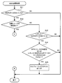
- the mobile station 100 confirms whether the generation of BSR is triggered.
- the mobile station 100 determines whether the transmission resource for transmitting new data is set regardless of whether it is based on DS or SPS. Check.
- the mobile station 100 performs the following process when transmission resources are set.
- the mobile station 100 transmits SR when the following conditions (4) and (5) are satisfied when the regular BSR is included in the BSR whose generation is triggered. (4) SPS resource is not set (5) Regular BSR is not triggered by the data of a specific logical channel
- the specific logical channel is a user data transmission / reception such as VoIP data
- VoIP data Is the logical channel used for Of the data transmitted from the mobile station 100
- a logical channel having a lower priority than data such as control data that is not particularly preferable for delay and that periodically and continuously transmits data is a specific logical channel. Should be specified.
- the “specific logical channel” in (5) is designated as a VoIP logical channel.
- the mobile station 100 first sets the BSR as a resource, divides a packet of data transmitted from the data buffer unit 102, multiplexes a part of the divided data with the BSR, and sets the same resource. To send.
- the BSR is not multiplexed with the packet, and the BSR is not transmitted.
- the mobile station 100 determines that the size of the VoIP data packet is equal to the size of the packet that can be transmitted by the SPS resource or the size of the VoIP data packet is smaller than the size of the packet that can be transmitted. Do not send BSR. Therefore, no DS resource is set from the base station 200 to the mobile station 100.
- the mobile station 100 can set the SPS cycle in which the SPS resource is set to a cycle obtained by alternately repeating a section obtained by adding or subtracting the reference cycle with a specified time. For example, if the reference period is 20 ms and the specified time is 5 ms, two different periods of 25 ms and 15 ms are alternately set as the SPS period, such as 25 ms, 15 ms, 25 ms, 15 ms,. The This is to prevent a new transmission processing timing in the same process and a retransmission processing timing due to an error from colliding in a short time in the HARQ processing in LTE TDD mode.
- the above-described reference period of the SPS period is an example, and an arbitrary interval may be set.
- the specified time of the SPS cycle described above is an example, and an arbitrary time may be set.
- the SPS cycle may be a fixed cycle with an arbitrary interval.
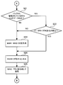
- the mobile station 100 of the second embodiment will be described in detail later with reference to FIGS. 14 and 15, but when BSR is triggered, the transmission resource used for transmission of new data from the mobile station 100 is the mobile station. It is determined whether it is set to 100. Here, it does not matter whether the transmission resource is a DS resource or an SPS resource, and does not affect the determination result.
- the mobile station 100 requests the scheduling resource from the base station 200.
- the mobile station 100 determines the following conditions (D) and (E).
- the type of data stored in the data buffer unit 102 is only data of a specific logical channel.
- E The size of the RLC SDU transmitted first and the RLC SDU transmitted at the time. The size of the packet that can be transmitted by the MAC PDU transmission resource is compared, and the RLC SDU transmitted first in the MAC PDU transmission resource can be incorporated without being divided.
- the condition (D) In addition, it is a condition for confirming that there is no data in the data buffer unit 102 to be transmitted even if the DS resource is used, such as control data and FTP data.
- “data of a specific logical channel” is VoIP data.
- Condition (E) is a condition for confirming that the size of the VoIP packet to be transmitted is not larger than the size that can be transmitted with the assumed SPS resource due to header compression and cancellation of ROHC (RObust Header Compression). It is.
- the compression of the ROHC header may be released based on a change in the communication environment. At this time, the size of the VoIP packet increases. As a result, it may be necessary to divide the VoIP packet when it is incorporated into the MAC PDU.
- the mobile station 100 determines that it can transmit the VoIP packet transmitted at the earliest point with one SPS resource, and generates a BSR. Without canceling the BSR trigger. Then, the mobile station 100 generates a MAC PDU that transmits the VoIP packet transmitted first. As a result, the BSR is not incorporated into the MAC PDU and transmitted to the base station 200.
- “data of a specific logical channel” is VoIP data, but is not limited to this, real-time data such as moving image data, and other user data transmitted from the mobile station 100 Also good.
- FIG. 13 is a timing chart illustrating resource setting operations in the wireless communication system according to the second embodiment.
- the VoIP packets 50 a and 50 b are voice encoded data packets generated by the application unit 141 of the mobile station 100.
- the SPS resources 260, 261, 262, 263, and 264 are SPS resources set from the base station 200 to the mobile station 100 in the SPS cycle.
- the DS resource 271 is an unnecessary DS resource in which the setting from the base station 200 to the mobile station 100 is suppressed.
- the VoIP packet 53 a is a VoIP packet corresponding to the VoIP packet 50 a and is a VoIP packet transmitted from the mobile station 100 to the base station 200 using the SPS resource 262.
- the VoIP packet 53b is a VoIP packet corresponding to the VoIP packet 50b, and is a VoIP packet transmitted from the mobile station 100 to the base station 200 using the SPS resource 263.
- the voice encoding cycle in which the VoIP packet is generated is, for example, 20 ms.
- the SPS cycle in which the SPS resource is set is set so that two different cycles of 25 ms and 15 ms are alternately continued, with the reference cycle being, for example, 20 ms and the specified time being, for example, 5 ms.
- two VoIP packets may be generated in one SPS period.
- two VoIP packets 50a and 50b are received by the layer 2 unit 120 during one SPS period under such conditions.
- the mobile station 100 triggers generation of a regular BSR.
- the logical channel of VoIP data is designated as “specific logical channel”.
- the specific logical channel is a logical channel that is used for transmission / reception of user data, and is a logical channel that transmits data having a lower priority than data such as control data in which delay is not particularly desirable.
- the layer 2 unit 120 receives from the application unit 141 the VoIP packet 50b to be transmitted next, which is generated after the voice encoding cycle has elapsed since the generation of the VoIP packet 50a. Shall be. It is assumed that VoIP packets are transmitted in the order received by the layer 2 unit 120.
- the data buffer unit 102 stores the VoIP packet 50a transmitted first and the VoIP packet 50b transmitted next. That is, data with the same priority is already stored. Also, it is assumed that the condition (C) is not met. Accordingly, since none of the conditions (A) to (C) is satisfied, the mobile station 100 does not trigger the generation of the BSR.
- the mobile station 100 attempts to transmit the VoIP packet 50 a at the data transmission timing by the SPS resource 262.
- the data buffer unit 102 stores the VoIP packet 50a transmitted first and the VoIP packet 50b transmitted next. That is, since only the VoIP packets 50a and 50b that are data of a specific logical channel are stored in the data buffer unit 102, the condition (D) is satisfied.
- the condition (E) Is satisfied.
- the VoIP packet 50b is divided, and a part of the divided VoIP packet 50b is multiplexed with the VoIP packet 50a, and the mobile station 100 To the base station 200.
- the base station 200 acquires the VoIP packet 53a corresponding to the VoIP packet 50a (or a part of the VoIP packet 53b corresponding to a part of the VoIP packet 53a and the divided VoIP packet 50b) from the received SPS resource 262. .
- the base station 200 determines that there is no DS resource request from the mobile station 100 because the received SPS resource 262 does not include the BSR. For this reason, the base station 200 does not set the DS resource 271 for the mobile station 100.
- the next VoIP packet 50b (or the remainder of the divided VoIP packet 50b) is transmitted from the mobile station 100 to the base station 200 using the SPS resource 263. Is done.
- the base station 200 acquires the VoIP packet 53b corresponding to the VoIP packet 50b (or the remainder of the VoIP packet 53b corresponding to the remainder of the divided VoIP packet 50b) from the received SPS resource 263.
- the timing of the transmission resource is set according to a certain rule as described above, but has a slight fluctuation.
- the mobile station 100 it is assumed that only the data of one VoIP packet 50a is stored in the data buffer unit 102 as shown in FIG. 13B. At this point, it is further assumed that a new VoIP packet 50b is received by the layer 2 unit 120.
- the reference period of the SPS period and the size of the packet that can be transmitted by the SPS resource are sufficiently set according to the voice encoding period and the size of the VoIP packet.
- the DS resource is not used, and transmission processing is continued only with the SPS resources. There is a high possibility that it will eventually be leveled and resolved.
- the mobile station 100 determines that the subsequent VoIP packet is not generated if there is no sudden large amount of data. Transmission can be continued without stagnation.
- the mobile station does not make the determination of the above conditions (D) and (E). It is assumed that the BSR is similarly triggered at the time shown in FIG. For this reason, when the BSR is generated in FIG. 13C, the VoIP packet 50 a is transmitted using the SPS resource 262. In this case, since the VoIP packet 50b, which is the second VoIP packet, is stored in the buffer at the time of FIG. 13C, a BSR indicating the size of the VoIP packet 50b is transmitted to the base station. Become. Based on this, since the size of the second VoIP packet is indicated in the BSR, the base station determines that the DS resource is requested from the mobile station, and sets the DS resource 271 to the mobile station. Will do.
- the mobile station transmits the VoIP packet 50b using the set DS resource 271.
- the SPS resource 263 since the VoIP packet 50b has already been transmitted to the base station and the VoIP packet does not exist in the buffer, the SPS resource 263 is not used. Accordingly, the next SPS resource is not used and is wasted, and the resource may not be used efficiently.
- the DS resource uses a resource that is common to other user data, if an unnecessary DS resource is set, the setting of the DS resource for the other user data is hindered and the other user data resources are compressed. there's a possibility that. Even when the SPS period is all constant, two VoIP packets are similarly generated during one SPS period due to speech encoding timing, layer 2 processing delay, and the like. It can happen.
- the mobile station 100 compares the size of the VoIP packet 50a with the size of the packet that can be transmitted by the SPS resource 262 according to the condition (E). Then, as a result of the comparison, when the mobile station 100 can be incorporated into the transmission resource of the MAC PDU to be transmitted without being divided, the SPS is not requested from the base station 200 for the DS resource 271 as described above.
- the packet 50b is transmitted by the resource 262. Thereby, since generation
- FIG. 14 and FIG. 15 are flowcharts showing the BSR transmission processing of the second embodiment.
- the BSR transmission process is executed for each TTI, for example.
- TTI is set to 1 ms.
- the present invention is not limited to this, and the TTI can be set to an arbitrary time interval as necessary.
- the processing illustrated in FIGS. 14 and 15 will be described in order of step number.
- Step S11 The control unit 151 determines whether or not the BSR is triggered.
- the BSR unit 126a starts generating the BSR.
- the BSR that has been generated by the BSR unit 126a based on the BSR trigger is transmitted to the base station 200 as the BSR MAC CE generated in step S23. If the BSR is triggered (step S11: YES), the controller 151 advances the process to step S12. On the other hand, if the BSR is not triggered (step S11: NO), the control unit 151 ends the process.
- Step S12 The control unit 151 determines whether or not a transmission resource used for transmitting new data from the mobile station 100 to the base station 200 is set for the mobile station 100. Here, in the determination in step S12, it does not matter whether the set transmission resource is DS or SPS. If the transmission resource is set (step S12 YES), the control unit 151 advances the process to step S21 (FIG. 15). On the other hand, if the transmission resource is not set (step S12: NO), the control unit 151 advances the process to step S13.
- Step S13 The control unit 151 determines whether or not the regular BSR is triggered, that is, whether or not the BSR determined to be triggered in step S11 is the regular BSR. If the regular BSR has been triggered (YES in step S13), the control unit 151 advances the process to step S14. On the other hand, if the regular BSR is not triggered (NO in step S13), the control unit 151 ends the process.
- Step S14 The control unit 151 determines whether an SPS resource is not set for the mobile station 100, and determines whether the regular BSR is triggered by a type of data other than VoIP data. To do. The control unit 151 further determines whether one of the two determination conditions is satisfied. If at least one of the two determination conditions in step S14 is satisfied (YES in step S14), the control unit 151 advances the process to step S15. On the other hand, if neither of the two determination conditions in step S14 is satisfied (NO in step S14), the control unit 151 ends the process.
- the control unit 151 has a higher priority than the VoIP data, and when the BSR is triggered by data other than the VoIP data, such as control data for which the occurrence of delay is suppressed more than the VoIP data, the scheduling request (SR: Scheduling Request) Does not interfere with the trigger. Thereby, generation
- the control unit 151 determines whether the regular BSR is triggered by data of a type other than VoIP data as one of the determination conditions.
- the present invention is not limited to this, and the regular BSR is triggered by data other than other types of data transmitted from the mobile station 100 using transmission resources, such as real-time data other than VoIP data such as moving image data. It may be determined whether or not.
- Step S15 The control unit 151 triggers a scheduling request. Thereby, transmission of a scheduling request is started. Thereafter, the control unit 151 ends the process.
- Step S21 The control unit 151 determines whether the type of data stored in the data buffer unit 102 is only VoIP data that is data of a specific logical channel. If the type of data stored in the data buffer unit 102 is only VoIP data (step S21 YES), the control unit 151 advances the process to step S22. On the other hand, if the type of data stored in the data buffer unit 102 includes data transmitted through another logical channel such as control data or other types of user data (NO in step S21), the control unit 151 Advances the process to step S23.
- a BSR MAC CE is generated in step S23. Is done. Thereby, while suppressing generation of useless DS resources based on VoIP data, it is possible to suppress occurrence of delay of control data that has a higher priority than VoIP data and is desired to suppress occurrence of delay more than VoIP data. Further, it is possible to suppress the influence on the transmission of the VoIP packet due to the delay due to the user data other than the VoIP data that occurs relatively irregularly staying in the data buffer unit 102.
- Step S22 The control unit 151 establishes a data size determination expression (expression (1) below) indicating whether or not the packet of VoIP data transmitted first can be transmitted by SPS without being divided. It is determined whether or not to do. If the data size determination formula is established (YES in step S22), the process proceeds to step S24. Accordingly, since the VoIP data transmitted first can be transmitted by SPS without being divided, the control unit 151 does not generate the BSR MAC CE. On the other hand, if the data size determination formula does not hold (NO in step S22), the VoIP data transmitted first is not transmitted by SPS without being divided, and the control unit 151 generates the BSR MAC CE. The process proceeds to step S23.
- a data size determination expression expression (1) below
- the designated MAC PDU is a MAC PDU of a transmission resource used for next transmission of data from the mobile station 100.
- the RLC SDU is the size of the RLC SDU of the VoIP packet transmitted first.
- the size of the RLC header is set to be equal to that of one RLC SDU in order to determine whether or not transmission is possible without dividing one RLC SDU in the mobile station 100 of the second embodiment. Since the size is used, it is a fixed value.
- the size of the MAC header changes based on the presence or absence of the MAC CE included in the designated MAC PDU.
- the size of the MAC CE changes based on the type of MAC CE included in the designated MAC PDU.
- the data type stored in the data buffer unit 102 is only VoIP data
- other types of data other than the VoIP data control data, etc.
- the existence of is excluded. Therefore, it is possible to use all of the area in the designated MAC PDU, which is the SPS resource for transmitting VoIP data, to which data can be transmitted for the transmission of VoIP data. For this reason, the size of RLC SDUs and RLC headers of other types of data can be excluded from the data size determination formula.
- the data size determination formula is an example, and can be arbitrarily set according to the priority between data and the size of each data or header.
- the data size determination formula is determined using the formula (1).
- the mobile station 100 does not request a DS resource when the VoIP data scheduled to be transmitted stored in the data buffer unit 102 can be transmitted using one SPS resource.
- the present invention is not limited to this, and determination may be made using the following equation (2) as a data size determination equation.
- the VoIP data scheduled to be transmitted stored in the data buffer unit 102 can be transmitted with a predetermined number n of SPS resources, the data is transmitted with the SPS without requesting the DS resource.
- the estimated resource size is an estimated value of the size of a packet that can be transmitted by the transmission resource set in the SPS by the scheduling by the base station 200.
- the size of the RLC header is a size corresponding to n RLC SDUs to determine whether or not n RLC SDUs can be transmitted, and is a fixed value if n is constant.
- the size of the scheduled transmission RLC SDU is calculated by counting and summing the sizes of the scheduled RLC SDUs.
- Step S23 The control unit 151 generates a BSR MAC CE, which is a MAC CE including a BSR indicating the amount of data to be transmitted stored in the data buffer unit 102 at that time.
- the control unit 151 executes step S24, which will be described later, following step S23, thereby releasing the trigger of the BSR based on the generation of the BSR MAC CE in step S23.
- Step S24 The control unit 151 cancels the BSR trigger. Thereby, the generation of the started BSR is canceled, and the BSR is not generated until the BSR is triggered again.
- Step S25 The control unit 151 performs control to generate a MAC PDU based on the RLC PDU of data to be transmitted, and incorporates the generated MAC PDU into the set transmission resource and transmits the MAC PDU to the base station 200. I do. Thereafter, the control unit 151 ends the process.
- a MAC PDU including a BSR indicating the amount of data stored in the data buffer unit 102 at that time generated in step S23 is generated in step S25 and transmitted to the base station 200.
- the base station 200 controls whether or not a DS resource is set for the mobile station 100.
- the determination process in step S14 is executed.
- the present invention is not limited to this, and the determination process in step S13 and the determination process in step S14 may be interchanged.
- the determination process in step S22 is executed.
- the present invention is not limited to this, and the determination process in step S21 and the determination process in step S22 may be interchanged.
- the process of step S25 is performed.
- the processing in step S24 may be executed after the processing in step S25 and the processing in step S25 are interchanged and the processing in step S25 is executed.
- the control unit 151 compares the size of the RLC SDU 43c2 with the size of the packet that can be transmitted by the SPS resource 262, and requests the setting of the DS resource 271. To control. As a result, it is determined whether there is a possibility that the VoIP packet read from the data buffer unit 102 is continuously stagnant from the comparison between the size of the RLC SDU 43c2 and the size that can be transmitted by the SPS resource 262. Thus, the request for setting the DS resource 271 is controlled.
- the base station 200 is not requested to set the DS resource 271.
- the base station 200 is not requested to set the DS resource 271.
- the DS resource 271 transmits data such as control data that cannot be relatively delayed, and the occurrence of the delay can be suppressed.
- the BSR MAC CE is not included in the MAC PDU 44a transmitted by the SPS resource 262. This makes it possible to increase the transmittable size of the RLC SDU 43c2 in the SPS resource 262 by the size of the BSR MAC CE. In addition, when setting the size of a packet that can be transmitted by the SPS resource, it can be reduced by the size of the BSR MAC CE.
- the base station 200 does not set the DS resource 271 for the mobile station 100 when the BSR from the mobile station 100 is not transmitted. Thereby, useless DS resources 271 are suppressed, and a decrease in resource utilization efficiency can be suppressed.
- the wireless communication system according to the third embodiment is different from the second embodiment in that, when it is determined that the data size determination formula is satisfied, “0 Byte” is set as the buffer data amount reported by the mobile station in the BSR. And different.
- FIG. 16 is a block diagram illustrating a wireless communication system according to the third embodiment.
- the wireless communication system according to the third embodiment includes a mobile station 500 and a base station 600.
- the wireless communication system according to the third embodiment can transmit and receive user data such as VoIP data and control data for controlling transmission and reception of user data between the mobile station 500 and the base station 600.
- the base station 600 can set the SPS resources 661 and 662 at regular intervals and the DS resource 671 according to the request of the mobile station 500 to the mobile station 500.
- the mobile station 500 can transmit data to the base station 600 using the SPS resources 661 and 662 and the DS resource 671 set from the base station 600.
- the SPS resources 661 and 662 are examples of first transmission resources (rule transmission resources) for which allocation is reserved in advance.
- the DS resource 671 is an example of a second transmission resource (dynamic transmission resource).
- SPS resources 661 and 662 are set at a cycle in which a period obtained by adding or subtracting a SPS cycle to a reference cycle at a specified time is alternately repeated.
- the reference period of the SPS period is an example, and an arbitrary interval may be set.
- the designated time of the SPS cycle is an example, and an arbitrary time may be set.
- the SPS cycle may be a fixed cycle with an arbitrary interval.
- the mobile station 500 includes a data buffer unit 502, a control unit 551, a MAC PDU generation unit 552, and a transmission unit 553.
- the mobile station 500 is an example of the wireless communication device 1.
- the data buffer unit 502 temporarily stores user data and control data such as VoIP data transmitted from the mobile station 500 to the base station 600.
- the data buffer unit 502 can be realized by, for example, a RAM such as an SRAM or another storage device.
- the control unit 551 compares the size of the RLC SDU 543c2 to be transmitted with the size of a packet that can be transmitted by the SPS resource 662 that transmits the RLC SDU 543c2.
- the control unit 551 controls the DS resource 671 setting request for the base station 600 according to the comparison result.
- the control unit 551 controls the MAC PDU generation unit 552 and the transmission unit 553 to indicate that the setting of the DS resource 671 is unnecessary. Send.
- the BSR 544 a 1 is included in the MAC PDU 544 a as a BSR MAC CE by the MAC PDU generation unit 552, and the MAC PDU 544 a including the BSR MAC CE is transmitted to the base station 600 by the transmission unit 553.
- the base station 600 does not set the DS resource 671 for the mobile station 500 when the buffer data amount included in the BSR 544a1 transmitted from the mobile station 500 is equal to or less than a predetermined threshold (for example, “0 bytes”). And Also, the base station 600 may not set the DS resource 671 for the mobile station 500 when the buffer data amount included in the BSR 544a1 transmitted from the mobile station 500 is “0 Byte”.
- the control unit 551 sets the buffer data amount stored in the data buffer unit 502 to a predetermined threshold value or less. Control is performed to transmit the BSR 544a1 (for example, set to “0 Byte”) to the base station 600. Accordingly, the base station 600 that has received the BSR 544a1 compares the buffer data amount indicated in the BSR with a predetermined threshold (for example, “0 Byte”) and is equal to or less than the predetermined threshold. The resource 671 is not set.
- the control unit 551 can be realized by the CPU 101 of the second embodiment, for example.
- the BSR 544a1 is an example of a resource request.
- the predetermined threshold value is not limited to “0 Byte”, and an arbitrary positive value may be set.
- the size of the packet that can be transmitted by the SPS resource 662 varies depending on the size of the MAC header of the SPS resource 662, the type of MAC CE included in the MAC PDU, and the like.
- the control unit 551 calculates the size of a packet that can be transmitted by the SPS resource 662 each time the SPS resource 662 that transmits the RLC SDU 543c2 is compared with the size of the RLC SDU 543c2.
- the present invention is not limited to this, and the control unit 551 may compare the size of a packet that can be transmitted by the SPS resource 662 using a preset fixed value.
- control unit 551 performs the above-described comparison and determines whether or not the data transmitted to the base station 600 stored in the data buffer unit 502 is only data of a specific logical channel.
- the control unit 551 controls the DS resource 671 setting request for the base station 600 according to the comparison result and the determination result. Regardless of the comparison result, the control unit 551 sets the DS resource 671 for the base station 600 when the data transmitted to the base station 600 stored in the data buffer unit 502 includes data other than a specific logical channel. Perform the requested control.
- the data of the specific logical channel is VoIP data. It is assumed that VoIP data is constantly transmitted from the mobile station 500 to the base station 600.
- the data such as control data that is not allowed to be delayed or the FTP data that may be generated irregularly and in large quantities is transmitted by the DS resource.
- the data of a specific logical channel is an example of a predetermined type of data. Note that when real-time data is constantly transmitted from the mobile station 500 to the base station 600, the data of the specific logical channel may be real-time data.
- the control unit 551 indicates to the base station 600 that the buffer data amount is equal to or smaller than a predetermined threshold. Control is performed to transmit the BSR 544a1 including the information.
- the MAC PDU generation unit 552 adds the RLC PDU generated by adding the RLC header to the RLC SDU 543c2, the MAC header, the MAC CE such as the BSR 544a1, and the RLC SDU of other logical channels.
- a MAC PDU 544a is generated.
- the MAC PDU generation unit 552 sets the buffer data amount of the BSR 544a1 included in the MAC PDU 544a to be equal to or less than a predetermined threshold when the size of the RLC SDU 543c2 is less than or equal to the size that can be transmitted by the SPS resource 662 according to the control of the control unit 551. . Thereby, the setting of the unnecessary DS resource 671 by the base station 600 can be suppressed.
- the MAC PDU generation unit 552 can be realized by, for example, the layer 2 unit 120 of the second embodiment.
- the transmission unit 553 transmits the MAC PDU 544 a generated by the MAC PDU generation unit 552 to the base station 600 based on the control of the control unit 551.
- the transmission unit 553 can be realized by the layer 1 unit 110 of the second embodiment, for example.
- the base station 600 has a resource setting unit 651.
- the resource setting unit 651 controls the setting of the DS resource 671 for the mobile station 500 according to the control of the DS resource 671 setting request from the mobile station 500.
- the resource setting unit 651 sets the DS resource 671 for the mobile station 500 when the amount of buffer data included in the BSR 544a1 transmitted from the mobile station 500 exceeds a predetermined threshold.
- the resource setting unit 651 sets the DS resource 671 for the mobile station 500 when the amount of buffer data included in the BSR 544a1 transmitted from the mobile station 500 is not less than a predetermined threshold.
- Base station 600 is an example of wireless communication apparatus 2.
- FIGS. 17 and 18 are flowcharts showing the BSR transmission processing of the third embodiment.
- the BSR transmission process is executed for each TTI, for example.
- TTI is set to 1 ms.
- the present invention is not limited to this, and the TTI can be set to an arbitrary time interval as necessary.
- the processing illustrated in FIGS. 17 and 18 will be described in order of step number.
- Step S31 The control unit 551 determines whether or not the BSR is triggered. If the BSR has been triggered (step S31: YES), the control unit 551 advances the process to step S32. On the other hand, if the BSR has not been triggered (step S31: NO), the control unit 551 ends the process.
- Step S32 The control unit 551 determines whether or not transmission resources used for transmission of new data from the mobile station 500 to the base station 600 are set for the mobile station 500. If the transmission resource is set (step S32 YES), the control unit 551 advances the processing to step S41 (FIG. 18). On the other hand, if the transmission resource is not set (step S32: NO), the control unit 551 advances the process to step S33.
- Step S33 The control unit 551 determines whether or not the regular BSR is triggered. If the regular BSR has been triggered (step S33: YES), the control unit 551 advances the process to step S34. On the other hand, if the regular BSR is not triggered (NO in step S33), the control unit 551 ends the process.
- Step S34 The control unit 551 determines whether or not an SPS resource is set for the mobile station 500, and determines whether or not the regular BSR is triggered by a type of data other than VoIP data. To do. The control unit 551 further determines whether one of the two determination conditions is satisfied. If at least one of the two determination conditions in step S34 is satisfied (YES in step S34), the control unit 551 advances the process to step S35. On the other hand, if neither of the two determination conditions in step S34 is satisfied (step S34 NO), the control unit 551 ends the process. In step S34 of the third embodiment, the control unit 551 determines whether the regular BSR is triggered by a type of data other than VoIP data as one of the determination conditions. However, the present invention is not limited to this, and the regular BSR is triggered by data other than other types of data transmitted from the mobile station 500 using transmission resources, such as real-time data other than VoIP data such as moving image data. It may be determined whether or not.
- Step S35 The control unit 551 triggers a scheduling request. Thereby, transmission of a scheduling request is started. Thereafter, the control unit 551 ends the process.
- Step S41 The control unit 551 determines whether the type of data stored in the data buffer unit 502 is only VoIP data that is data of a specific logical channel. If the type of data stored in the data buffer unit 502 is only VoIP data (YES in step S41), the control unit 551 advances the process to step S42. On the other hand, if the type of data stored in the data buffer unit 502 includes data transmitted through other logical channels such as control data and other types of user data (NO in step S41), the control unit 551 is used. Advances the process to step S43. As a result, when control data or user data of another service is stored in the data buffer unit 502, a BSR MAC CE is generated in step S43.
- Step S42 The control unit 551 establishes a data size determination equation (the above-described equation (1)) indicating whether or not the packet of VoIP data transmitted first can be transmitted by SPS without being divided. It is determined whether or not. If the data size determination formula is satisfied (YES in step S42), the process proceeds to step S44. Accordingly, since the VoIP data transmitted first can be transmitted by SPS without being divided, the control unit 551 does not generate the BSR MAC CE. On the other hand, if the data size determination formula is not satisfied (NO in step S42), the VoIP data transmitted first cannot be transmitted by SPS without being divided, and the control unit 551 generates the BSR MAC CE. The process proceeds to step S43.
- a data size determination equation the above-described equation (1)
- the data size determination formula is determined using the formula (1).
- the VoIP data scheduled to be transmitted stored in the data buffer unit 502 can be transmitted with one SPS resource, the mobile station 500 does not request a DS resource.
- the present invention is not limited to this, and the above-described equation (2) may be used as the data size determination equation.
- the VoIP data scheduled to be transmitted stored in the data buffer unit 502 can be transmitted with a predetermined number n of SPS resources, the data is transmitted with the SPS without requesting the DS resource.
- Step S43 The control unit 551 generates a BSR MAC CE that is a MAC CE including a BSR indicating the amount of data to be transmitted stored in the data buffer unit 502 at the time.
- the control unit 551 executes step S45, which will be described later, following step S43, thereby releasing the BSR trigger based on the generation of the BSR MAC CE in step S43.
- Step S44 The control unit 551 generates a BSR MAC CE indicating “0 Byte” regardless of the amount of data to be transmitted stored in the data buffer unit 502 at that time. Thereby, the buffer data amount of the data buffer unit 502 reported from the mobile station 500 to the base station 600 by the BSR is reported to be “0 Byte” irrespective of the actually stored data amount. In accordance with this, it is possible to perform control so that the DS resource is not set from the base station 600 to the mobile station 500 based on the BSR transmitted from the mobile station 500.
- step S45 to be described later is executed following step S43.
- Step S45 The control unit 551 cancels the BSR trigger.
- Step S46 The control unit 551 performs control to generate a MAC PDU based on the RLC PDU of data scheduled to be transmitted, and controls the generated MAC PDU to be incorporated into the set transmission resource and transmitted to the base station 600. I do. Thereafter, the control unit 551 ends the process.
- a MAC PDU including a BSR indicating the amount of data stored in the data buffer unit 502 at that time generated in step S43 is generated in step S46 and transmitted to the base station 600.
- the base station 600 controls whether or not a DS resource is set for the mobile station 500.
- the determination process in step S34 is executed.
- the present invention is not limited to this, and the determination process in step S33 and the determination process in step S34 may be interchanged.
- the determination process in step S42 is executed.
- the present invention is not limited to this, and the determination process in step S41 and the determination process in step S42 may be interchanged.
- the process of step S46 is performed.
- step S45 may be executed after the processing in step S46 and the processing in step S46 are interchanged and the processing in step S46 is executed. Further, the process of step S45 may be executed before the process of step S43 and the process of step S44.
- the same effects as those of the second embodiment can be obtained. Furthermore, in the third embodiment, when the size of the RLC SDU 543c2 is equal to or smaller than the size that can be transmitted by the SPS resource 662, the buffer data amount reported by the BSR 544a1 is reported as being equal to or less than a predetermined threshold (or “0 bytes”). Thereby, it is clearly notified by the transmission of BSR 544a1 from mobile station 500 to base station 600 that setting of DS resource 671 is unnecessary.
- the buffer data amount of the data buffer unit 502 reported by the BSR 544a1 is reported as being equal to or less than a predetermined threshold (or “0 bytes”).
- a predetermined threshold or “0 bytes”.
- the wireless communication system provides management information used for managing the data buffer unit, and manages when a new VoIP packet is stored in the data buffer unit when the addition availability timer has expired. Suppress information updates.
- the buffer data amount indicated by the management information is set to the buffer data amount reported by the BSR. This is different from the second embodiment in that the amount of VoIP packet data reported from the mobile station by BSR in one SPS cycle is suppressed.
- FIG. 19 is a block diagram illustrating a wireless communication system according to the fourth embodiment.
- the wireless communication system according to the fourth embodiment includes a mobile station 700 and a base station 800.
- the radio communication system according to the fourth embodiment can transmit and receive user data such as VoIP data and control data for controlling transmission and reception of user data between the mobile station 700 and the base station 800.
- the base station 800 can set the SPS resources 861 and 862 at regular intervals and the DS resource 871 according to the request of the mobile station 700 to the mobile station 700.
- the mobile station 700 can transmit data to the base station 800 using the SPS resources 861 and 862 and the DS resource 871 set from the base station 800.
- the SPS resources 861 and 862 are examples of first transmission resources (rule transmission resources) for which allocation is reserved in advance.
- the DS resource 871 is an example of a second transmission resource (dynamic transmission resource).
- SPS resources 861 and 862 are set at a cycle in which a section obtained by adding or subtracting the SPS cycle to the reference cycle at a specified time is alternately repeated.
- the interval between the SPS resources 861 and 862 includes a longer period in which the time obtained by adding the reference period and the designated time is one period, and a shorter period in which the time obtained by subtracting the designated time from the reference period is one period. It is set alternately.
- the reference period of the SPS period is an example, and an arbitrary interval may be set.
- the designated time of the SPS cycle is an example, and an arbitrary time may be set.
- the SPS cycle may be a fixed cycle with an arbitrary interval.
- the mobile station 700 includes a data buffer unit 702, a control unit 751, a MAC PDU generation unit 752, a transmission unit 753, a management information storage unit 754, and an addition availability timer 755.
- the mobile station 700 is an example of the wireless communication device 1.
- the data buffer unit 702 temporarily stores user data and control data such as VoIP data transmitted from the mobile station 700 to the base station 800.
- the data buffer unit 702 can be realized by, for example, a RAM such as an SRAM or another storage device.
- the control unit 751 acquires data stored in the data buffer unit 702 at the timing of data transmission by the SPS resources 861 and 862, and sets the acquired data in the management information 7541 stored in the management information storage unit 754 To do. Thereby, the buffer data amount that is the data amount of the data stored in the data buffer unit 702 is set in the management information 7541.
- the control unit 751 can be realized by the CPU 101 of the second embodiment, for example.
- the control unit 751 deletes the data corresponding to the discarded data from the management information 7541 stored in the management information storage unit 754. As a result, the data amount of the discarded data is subtracted from the buffer data amount of the management information 7541.
- the control unit 751 keeps time with the addition permission / rejection timer 755 and sets the management information 7541 to the addition permission state until a predetermined period has elapsed from the timing of data transmission by the SPS resources 861 and 862.
- the length of the predetermined period may be set shorter than the longer cycle of the SPS and longer than the shorter cycle.
- the control unit 751 updates the management information 7541 stored in the management information storage unit 754 when new data is stored in the data buffer unit 702. That is, the control unit 751 sets newly stored data in the management information 7541 stored in the management information storage unit 754 in the addition permission state. As a result, the data amount of the newly stored data is added to the buffer data amount of the management information 7541.
- control unit 751 keeps time with the addition availability timer 755 and sets the management information 7541 to the addition refusal state after a predetermined period has elapsed from the timing of data transmission by the SPS resources 861 and 862.
- the control unit 751 does not update the management information 7541 stored in the management information storage unit 754 when new data is stored in the data buffer unit 702. That is, control unit 751 does not set newly stored data in management information 7541 in the addition refusal state. As a result, the data amount of the newly stored data is not added to the buffer data amount of the management information 7541.
- the control unit 751 controls the MAC PDU generation unit 752 and the transmission unit 753 to buffer data amount information indicating the buffer data amount indicated by the management information 7541 stored in the management information storage unit 754 with respect to the base station 800.
- BSR744a1 including The BSR 744 a 1 is included in the MAC PDU 744 a as the BSR MAC CE by the MAC PDU generation unit 752, and the MAC PDU 744 a including the BSR MAC CE is transmitted to the base station 800 by the transmission unit 753.
- the BSR 744a1 is an example of a resource request.
- the MAC PDU generation unit 752 Based on the control of the control unit 751, the MAC PDU generation unit 752 adds the MAC header, the MAC CE such as BSR744a1, the RLC SDU of other logical channels, etc. to the RLC PDU generated by adding the RLC header to the RLC SDU. In addition, a MAC PDU 744a is generated.
- the MAC PDU generation unit 752 can be realized by, for example, the layer 2 unit 120 of the second embodiment.
- the transmission unit 753 transmits the MAC PDU 744 a generated by the MAC PDU generation unit 752 to the base station 800 based on the control of the control unit 751.
- the transmission unit 753 can be realized by the layer 1 unit 110 according to the second embodiment, for example.
- the management information storage unit 754 stores management information 7541 used for managing the data buffer unit 702.
- the management information 7541 is updated by the control unit 751 based on the update of data transmitted to the base station 800 of the data buffer unit 702.
- the management information 7541 indicates the type of data and the amount of data set in the management information based on the update by the control unit 751.
- the control unit 751 stores the same data in the management information storage unit 754 as the management information 7541, thereby corresponding to the data stored in the data buffer unit 702. Management information 7541 is set.
- the control unit 751 deletes the data corresponding to the data discarded from the data buffer unit 702 from the management information storage unit 754, thereby changing the management information 7541. delete.
- the management information 7541 indicates the amount of buffer data to be reported to the base station 800 by the BSR 744a1 transmitted to the base station 800 next.
- the data type indicates whether the data indicated by the management information is control data or real-time data such as VoIP data or moving image data.
- the buffer data amount of the management information 7541 is a total value of the data amounts of the respective data set in the management information based on the update by the control unit 751.
- the management information storage unit 754 can be realized by, for example, a RAM such as an SRAM or another storage device.
- the addition permission / rejection timer 755 determines whether or not a predetermined period has elapsed from the timing of data transmission by the SPS resources 861 and 862 in order for the control unit 751 to switch and set the addition permission state and the addition rejection state in the management information 7541. This is a timer used for determination.
- the addition availability timer 755 can be realized by the CPU 101, for example.
- the base station 800 has a resource setting unit 851.
- the resource setting unit 851 controls the setting of the DS resource 871 for the mobile station 700 according to the control of the DS resource 871 setting request from the mobile station 700.
- the resource setting unit 851 sets the DS resource 871 for the mobile station 700 when the amount of buffer data included in the BSR 744a1 transmitted from the mobile station 700 exceeds a predetermined threshold.
- the resource setting unit 851 sets the DS resource 871 for the mobile station 700 when the buffer data amount included in the BSR 744a1 transmitted from the mobile station 700 is not less than or equal to a predetermined threshold.
- Base station 800 is an example of wireless communication apparatus 2.
- the predetermined threshold value may be set to “0 Byte” or any positive value.
- the control unit 751 generates a BSR 744a1 including buffer data amount information indicating the buffer data amount indicated by the management information 7541 stored in the management information storage unit 754 for the base station 800, and the generated BSR 744a1 is converted to the SPS. Transmit on resource 862.
- the present invention is not limited to this, and the control unit 751 may not generate the BSR 744a1 when the buffer data amount indicated by the management information 7541 is a predetermined value or less (for example, “0 Byte” or less). Further, the control unit 751 may not include the BSR 744a1 in the MAC PDU 744a of the SPS resource 862 when the buffer data amount indicated by the management information 7541 is equal to or less than a predetermined value.
- the transmittable size of the RLC SDU in the SPS resource 862 can be increased by the size of the BSR MAC CE. Further, when setting the size of the SPS resource, it can be reduced by the size of the BSR MAC CE.
- the management information storage unit 754 stores management information 7541 that is the same data as the data to be transmitted stored in the data buffer unit 702. However, the management information storage unit 754 is not limited to this, and the management information storage unit 754 sets information corresponding to the data to be transmitted stored in the data buffer unit 702 and information indicating the data amount and the type of data to be transmitted. Management information including may be stored.
- FIG. 20 is a timing chart illustrating an operation of setting resources in the wireless communication system according to the fourth embodiment.
- FIG. 21 is a diagram illustrating a data buffer unit and a management state during a resource setting operation in the wireless communication system according to the fourth embodiment. The operation of the mobile station 700 according to the fourth embodiment will be described below with reference to FIGS.
- VoIP packets 60g, 60i, and 60l in FIG. 20 are voice encoded data packets generated by the application unit of the mobile station 700.
- the SPS resources 860, 861, 862, 863, and 864 are SPS resources set from the base station 800 to the mobile station 700 in the SPS cycle.
- the DS resource 871 is an unnecessary DS resource in which the setting from the base station 800 to the mobile station 700 is suppressed.
- the VoIP packet 63g2 is a VoIP packet corresponding to the VoIP packet 60g, and is a VoIP packet transmitted from the mobile station 700 to the base station 800 using the SPS resource 862.
- the VoIP packet 63i2 is a VoIP packet corresponding to the VoIP packet 60i, and is a VoIP packet transmitted from the mobile station 700 to the base station 800 using the SPS resource 863.
- FIG. 21A shows the state of the data buffer unit 702 and the management information when the VoIP packet 60g is received by the layer 2 unit of the mobile station 700.
- FIG. 21B shows the state of the data buffer unit 702 and the management information when the VoIP packet 60 i is received by the layer 2 unit of the mobile station 700.
- FIG. 21C shows the state of the data buffer unit 702 and management information when the VoIP packet 60 i is transmitted from the mobile station 700 to the base station 800 using the SPS resource 862.
- FIG. 21D the data buffer unit 702 at the time of the data buffer unit 702 after the addition enable / disable timer 755 is restarted and addition update becomes possible and the buffer data amount of the data buffer unit 702 is reflected in the management information. And the status of management information.
- Data buffer units 702a, 702b, 702c, and 702d in FIG. 21 indicate the amount of buffer data actually stored in the data buffer unit 702 at each time point in FIGS. 21A to 21D.
- management information 754a, 754b, 754c, and 754d in FIG. 21 indicate the management information indicated by the management information storage unit 754 at each time point in FIGS. 21 (A) to (D).
- the data 64g is data indicating the VoIP packet 60g in the management information 754a and 754b.
- Data 64i is data indicating the VoIP packet 60i in the management information 754d.
- the speech encoding period is set to 20 ms, for example.
- the reference cycle is set to 20 ms and the specified time is set to 5 ms, for example, and two different cycles of 25 ms and 15 ms are alternately set.
- the addition availability timer 755 starts at the timing of the SPS resource 860.
- the timing of the SPS resource 861 comes after the elapse of the shorter SPS period (for example, 15 ms). Based on this, the addition availability timer 755 is restarted.
- the mobile station 700 when the mobile station 700 receives the first VoIP packet 60g generated by the application unit at the layer 2 unit, the mobile station 700 triggers the generation of the regular BSR. To do.
- the VoIP packet 60g is stored in the data buffer unit 702a, and the data 64g indicating the VoIP packet 60g is set in the management information 754a.
- the logical channel of VoIP data is designated as “specific logical channel”.
- the mobile station 700 since the condition (5) described above is not satisfied, transmission of a scheduling request is suppressed when a VoIP packet is generated. Accordingly, since the mobile station 700 does not request scheduling at this time, transmission of the VoIP packet is suspended until the next transmission timing by the SPS resource 862.
- the management information state is set to the addition refusal state after the elapse of the reference period that is the timer period of the addition permission / rejection timer 755. Based on this, even if the VoIP packet is stored in the data buffer unit 702 until the state of the management information shifts to the addable state by restarting the addition enable / disable timer 755, the storage of the VoIP packet is stored in the management information. Is not reflected.
- the mobile station 700 transmits a VoIP packet 60 i to be transmitted next, which is generated after the voice encoding cycle has elapsed since the generation of the VoIP packet 60 g transmitted first. It is assumed that the layer 2 part has received.
- the data buffer unit 702 stores the VoIP packet 60g transmitted first and the VoIP packet 60i transmitted next. That is, data with the same priority is already stored. Also, it is assumed that the condition (C) is not met. Accordingly, since none of the conditions (A) to (C) is satisfied, the mobile station 700 does not trigger the generation of the BSR. Also, at the time of FIG. 20 (h), the addition permission / inhibition timer 755 is set to the addition refusal state.
- the VoIP data generated immediately before the next SPS resource such as the VoIP packet 60i
- the reference period of the SPS period and the size of the packet that can be transmitted by the SPS resource are sufficiently set according to the voice encoding period and the size of the VoIP packet.
- fluctuations in processing of the SPS resource interval and speech coding interval and fluctuations in the amount of VoIP packets described above are eventually leveled and eliminated by continuing transmission processing using only SPS resources.
- the mobile station 700 attempts to transmit the VoIP packet 60 g at the timing of data transmission by the SPS resource 862.
- the data buffer unit 702 stores the VoIP packet 60g transmitted first and the VoIP packet 60i transmitted next.
- the size of the VoIP packet transmitted first can be incorporated without being divided into the transmission resources of the MAC PDU to be transmitted.
- the data stored in the data buffer unit 702c is stored in the VoIP packet as shown in FIG. 60i only.
- the management information 754c reflects the discard of the VoIP packet 60g from the data buffer unit 702, the data 64g indicating the VoIP packet 60g is discarded from the management information 754c, and no data exists. Accordingly, the management information 754c indicates that the buffer data amount is “0 Byte”. Accordingly, the mobile station 700 generates a BSR MAC CE based on the trigger at the time point of FIG. At this time, “0 Byte” that is the buffer data amount indicated by the management information 754c is set in the BSR MAC CE. Then, the mobile station 700 generates a MAC PDU that includes the generated BSR MAC CE and transmits the VoIP packet 60g that is transmitted first.
- the mobile station 700 incorporates the generated MAC PDU into the SPS 862 and transmits it.
- a BSR indicating that the buffer data amount is “0 Byte” is incorporated into the MAC PDU and transmitted to the base station 800.
- the SPS resource 862 which is the transmission resource of the MAC PDU that transmits the VoIP packet 60g
- the VoIP packet 60i is divided, and a part thereof is multiplexed with the VoIP packet 60g and the BSR, and the mobile station 700 May be transmitted to the base station 800 using the SPS resource 862, but the subsequent description is omitted.
- the base station 800 acquires the BSR 63g1 together with the VoIP packet 63g2 corresponding to the VoIP packet 60g from the received SPS resource 862.
- the base station 800 transmits a part of the VoIP packet 63i2 corresponding to the VoIP packet 63g2 and a part of the divided VoIP packet 60i.
- the base station 800 determines that the DS resource is not set for the mobile station 700 because the buffer data amount indicated by the BSR 63g1 included in the received SPS resource 862 is “0 Byte”. For this reason, the base station 800 does not set the DS resource 871 for the mobile station 700.
- the addition availability timer 755 is started.
- the management information is set to an addable state
- the state of the data buffer unit 702 is referred to and set to the management information. That is, as shown in FIG. 21D, the VoIP packet 60i shown in the data buffer unit 702d is reflected, and the data 64i is set in the management information 754d.
- the next VoIP packet 60i (or the remainder of the divided
- the VoIP packet 60 i transmitted by the SPS resource 863 is read from the data buffer unit 702 and discarded, there is no data stored in the data buffer unit 702.
- the management information reflects the discard of the VoIP packet 60i from the data buffer unit 702.
- the data 64g indicating the VoIP packet 60i is discarded from the management information, and no data exists.
- the mobile station 700 does not generate the BSR because the occurrence of the BSR is not triggered.
- the mobile station 700 transmits the VoIP packet 60 i to the base station 800 using the SPS resource 863.
- the addition availability timer 755 is started based on the transmission timing of the SPS resource 863.
- the base station 800 acquires the VoIP packet 63i2 corresponding to the VoIP packet 60i from the received SPS resource 863.
- the VoIP packet 60l generated by the application unit is received by the layer 2 unit.
- the mobile station 700 since data is not stored in the data buffer unit 702, the mobile station 700 triggers generation of a regular BSR.
- the data buffer unit 702 stores the VoIP packet 601 and sets data indicating the VoIP packet 601 in the management information.
- the mobile station 700 and the base station 800 repeat the same processing thereafter.
- a BSR indicating that the buffer data amount is “0 Byte” is generated, similarly to the VoIP packet 60 g.
- FIGS. 22 and 23 are flowcharts showing the addition permission / prohibition timer processing of the fourth embodiment.
- the addition permission / inhibition timer process is executed, for example, when the mobile station 700 starts a new VoIP communication.
- the processing illustrated in FIGS. 22 and 23 will be described in order of step number.
- Step S51 The control unit 751 sets the management information stored in the management information storage unit 754 to an addition refusal state in which the addition to be added is not performed, and sets the addition permission / prohibition timer to a stopped state that has not been started. To do. Thus, even if VoIP data is newly stored in the data buffer unit 702, the management information stored in the management information storage unit 754 is not added. Further, the addition availability timer is stopped.
- Step S52 The control unit 751 sets the data indicated by the management information to an initial state (for example, no data and the buffer data amount is “0 Byte”).
- Step S53 The control unit 751 determines whether or not the addition availability timer is operating. If the addition permission / prohibition timer is operating (step S53 YES), the controller 751 advances the process to step S54. On the other hand, if the addition permission / prohibition timer has not been started or has been stopped due to expiration (NO in step S53), control unit 751 advances the process to step S55.
- Step S54 The control unit 751 determines whether or not the set time of the addition availability timer has expired. If the addition availability timer has expired (YES in step S54), the control unit 751 advances the process to step S58. On the other hand, if the set time of the addition availability timer has not expired (step S54 NO), the control unit 751 advances the process to step S55.
- the set time of the addition enable / disable timer can be the reference time of the SPS resource as described above.
- Step S55 The control unit 751 determines whether it is a transmission timing of data transmitted by the SPS resource. If it is the transmission timing of the SPS resource (YES in step S55), the control unit 751 advances the process to step S56. On the other hand, if it is not the timing for transmitting the SPS resource (NO in step S55), the control unit 751 advances the process to step S62 (FIG. 23).
- Step S56 The control unit 751 starts an addition availability timer. As a result, the addition enable / disable timer is reset ("0" is set in the timer) and time counting is started. [Step S ⁇ b> 57]
- the control unit 751 sets the management information stored in the management information storage unit 754 to an addition-permitted state that can be updated to be added. As a result, when VoIP data is newly stored in the data buffer unit 702, the data amount of the newly stored VoIP data is added to the management information stored in the management information storage unit 754. Thereafter, the control unit 751 advances the process to step S61 (FIG. 23).
- Step S58 The control unit 751 sets the management information stored in the management information storage unit 754 to an addition refusal state in which updating for addition is not performed. Then, the control part 751 advances a process to step S62.
- Step S61 The control unit 751 acquires data stored in the data buffer unit 702, and sets the acquired data as management information.
- the control unit 751 determines whether or not the VoIP communication has ended. If the VoIP communication has ended (YES in step S62), the control unit 751 ends the process. On the other hand, if the VoIP communication has not ended (NO in step S62), the control unit 751 advances the process to step S53.
- the addition permission / prohibition timer is controlled based on the storage and discard of VoIP data, and the transmission resource in VoIP communication is controlled.
- the present invention is not limited to this, and the transmission resource in the data communication of the data described above may be controlled by controlling the addition enable / disable timer based on storage and discarding of user data such as other real-time data such as moving image data. .
- step S56 the process of step S57 is executed, and then the process of step S61 is executed.
- the present invention is not limited to this, and the order of execution of the processes of step S56, step S57, and step S61 may be changed.
- FIG. 24 is a flowchart illustrating a BSR transmission process according to the fourth embodiment.
- the BSR transmission process is executed for each TTI, for example.
- TTI is set to 1 ms.
- the present invention is not limited to this, and the TTI can be set to an arbitrary time interval as necessary. In the following, the process illustrated in FIG. 24 will be described in order of step number.
- Step S71 The control unit 751 determines whether or not the BSR is triggered. If the BSR has been triggered (YES in step S71), the control unit 751 advances the process to step S72. On the other hand, if the BSR is not triggered (step S71: NO), the control unit 751 ends the process.
- Step S72 The control unit 751 determines whether or not a transmission resource used for transmitting new data from the mobile station 700 to the base station 800 is set for the mobile station 700. If the transmission resource is set (step S72: YES), the control unit 751 advances the process to step S76. On the other hand, if no transmission resource is set (NO in step S72), the control unit 751 advances the process to step S73.
- Step S73 The control unit 751 determines whether or not the regular BSR is triggered. If the regular BSR has been triggered (step S73: YES), the controller 751 advances the process to step S74. On the other hand, if the regular BSR is not triggered (NO in step S73), the control unit 751 ends the process.
- Step S74 The control unit 751 determines whether or not an SPS resource is set for the mobile station 700, and determines whether or not the regular BSR is triggered by a type of data other than VoIP data. To do. The control unit 751 further determines whether one of the two determination conditions is satisfied. If at least one of the two determination conditions in step S74 is satisfied (YES in step S74), the control unit 751 advances the process to step S75. On the other hand, if neither of the two determination conditions in step S74 is satisfied (NO in step S74), the control unit 751 ends the process. In step S74 of the fourth embodiment, the control unit 751 determines whether the regular BSR is triggered by a type of data other than VoIP data as one of the determination conditions. However, the present invention is not limited to this, and the regular BSR is triggered by data other than other types of data transmitted from the mobile station 700 using transmission resources, such as real-time data other than VoIP data such as moving image data. It may be determined whether or not.
- Step S75 The control unit 751 triggers a scheduling request. Thereby, transmission of a scheduling request is started. Thereafter, the control unit 751 ends the process.
- Step S76 The control unit 751 generates a BSR MAC CE that is a MAC CE including a BSR indicating the amount of data to be transmitted stored in the data buffer unit 702 at the time.
- the control unit 751 executes step S77, which will be described later, following step S76, thereby releasing the trigger of the BSR based on the generation of the BSR MAC CE in step S76.
- Step S77 The control unit 751 cancels the BSR trigger.
- Step S78 The control unit 751 performs control to generate a MAC PDU based on the RLC PDU of data to be transmitted, and controls the generated MAC PDU to be transmitted to the base station 800 by being incorporated in the set transmission resource. I do. Thereafter, the control unit 751 ends the process.
- a MAC PDU including the BSR indicating the buffer data amount indicated by the management information stored in the management information storage unit 754 is generated in step S78 and transmitted to the base station 800.
- the base station 800 controls the mobile station 700 to set whether or not the DS resource is set based on the management information that does not perform the addition update of the data amount when the timer expires by the addition enable / disable timer process. Is done.
- step S74 when the result of the determination process in step S73 is YES, the determination process in step S74 is executed.
- the present invention is not limited to this, and the determination process in step S73 and the determination process in step S74 may be interchanged.
- step S76 after the process of step S76 is executed, the process of step S77 is executed.
- the processing order of step S76 may be executed after the processing order of step S76 and the processing order of step S77 are changed and the processing of step S77 is executed. Further, the process of step S78 may be executed before the process of step S77.
- FIG. 25 is a flowchart illustrating management information update processing according to the fourth embodiment.
- the management information update process is executed by the mobile station 700 when one of the following occurs.
- One of the triggers for the management information update process is when new data is stored in the data buffer unit 702 of the mobile station 700.
- Another trigger for the management information update process is that the data stored in the data buffer unit 702 is read to generate a MAC PDU, and the data stored in the data buffer unit 702 is discarded. Is the case.
- the process illustrated in FIG. 25 will be described in order of step number.
- Step S81 The control unit 751 determines whether or not the trigger for executing the management information update process is storage of new data in the data buffer unit 702. If the trigger is data storage (step S81: YES), the controller 751 advances the process to step S82. On the other hand, if the trigger is discard based on reading of data stored in the data buffer unit 702 (NO in step S81), the control unit 751 advances the process to step S83. As a result, if data is discarded from the data buffer unit 702, the change in the data in the data buffer unit 702 becomes the management information regardless of whether the management information is in the addition permission state or the addition rejection state. Reflected.
- Step S82 The control unit 751 determines whether or not the management information is in an addition-permitted state. If the management information is in the addition permission state (YES in step S82), the control unit 751 advances the process to step S83. On the other hand, if the management information is in the addition refusal state (step S82: NO), the control unit 751 ends the process. Thus, if the management information is in the addition-permitted state, the data indicated in the management information increases even when new data is stored in the data buffer unit 702. If the management information is in the addition refusal state, when new data is stored in the data buffer unit 702, the data indicated in the management information does not change.
- Step S ⁇ b> 83 The control unit 751 increases or decreases the buffer data amount indicated by the management information in response to new storage or discard of data stored in the data buffer unit 702 that triggered the execution of the management information update process. .
- the trigger for executing the management information update process is a new storage of data
- the amount of the newly stored data is added to the buffer data amount indicated by the management information.
- the management information update process is triggered when data is discarded, the amount of discarded data is subtracted from the buffer data amount indicated by the management information. Thereafter, the control unit 751 ends the process.
- the wireless communication system of the fourth embodiment when the data buffer unit 702 stays in a transitional state, the increase in the buffer data amount of the BSR is suppressed, thereby using the resources. Reduces efficiency loss. That is, in the fourth embodiment, regarding the update for adding the buffer data amount of the BSR 744a1, the period during which the update can be performed is the transmission of the SPS resource in one SPS cycle (the period between two SPS resources). The period is limited to a certain period. Accordingly, when the transmission timing of the next SPS resource is close, even if a new VoIP packet is stored in the data buffer unit 702, the buffer data amount of the data buffer unit 702 reported by the BSR 744a1 does not increase.
- the mobile station 700 it is assumed that only one VoIP packet is stored in the data buffer unit 702, and a new VoIP packet is generated when the transmission timing of the SPS resource is close.
- a newly generated VoIP packet is transmitted using the DS resource
- there is a possibility that there is no data to be transmitted using the next SPS resource for example, when no VoIP packet has been generated up to the next SPS resource.
- the VoIP packet generated thereafter is not changed as long as there is no other sudden transmission data.
- SPS resources can be transmitted sequentially without stagnation.
- the buffer data amount reported to base station 800 by BSR 744a1 is zero.
- the base station 800 that has received the BSR 744 a 1 indicating that the buffer data amount is 0 does not set the DS resource for the mobile station 700. In this way, by suppressing the generation of useless DS resources, a decrease in resource utilization efficiency is suppressed.
- the period until expiration of the addition availability timer 755 is set shorter than the longer period of SPS.
- the addition enable / disable timer 755 expires before the end of the longer SPS period in the mobile station 700, so that the addition of management information is rejected before the end of the longer SPS period, that is, immediately before the next SPS resource. Can be set to state. Accordingly, when two VoIP packets 60g and 60i are generated during the longer period of the SPS, the increase in the data amount of the data buffer unit 702 based on the second VoIP packet 60i is not reflected in the BSR 63g1. For this reason, since the request for the DS resource 871 is not performed in the mobile station 700, the request for the unnecessary DS resource 871 can be suppressed.
- the period until expiration of the addition availability timer 755 is set longer than the shorter period of the SPS.
- the addition enable / disable timer 755 does not expire during the shorter period of the SPS in the mobile station 700, so that the management information can be maintained in the addition permitted state during the shorter period of the SPS.
- an increase in the data amount of the data buffer unit 702 based on the second VoIP packet with the shorter period of the SPS is generated in the BSR 63g1. Reflected. Accordingly, a DS resource request is made based on the second VoIP packet having the shorter SPS period, and the second VoIP packet having the shorter SPS period can be transmitted using the DS resource.
- the shorter cycle of the SPS is shorter than the speech coding cycle.
- the cause is different from the above-described fluctuations in the processing of the SPS resource interval and speech encoding interval, such as sudden data generation. It is possible that For this reason, there is a high possibility that it cannot be absorbed when the transmission process is continued only with the SPS resource. Accordingly, by requesting the setting of the DS resource 871 and transmitting by the DS resource 871, transmission of the subsequent VoIP packets can be continued without staying.
- the radio communication system in a mobile station, when an RLC SDU transmitted to the base station is newly generated and stored in the data buffer unit, the RLC SDU is data other than a specific logical channel. It is determined whether it is (control data or the like). When the newly generated RLC SDU is data other than a specific logical channel, the update of the data buffer unit by the newly generated RLC SDU is reflected in the management information even in the addition refusal state. As a result, in the fourth embodiment, the amount of data of the VoIP packet reported from the mobile station by the BSR in one SPS cycle is suppressed, but addition of management information is not prevented for other types of data. Different from form.
- FIG. 26 is a block diagram illustrating a wireless communication system according to the fifth embodiment.
- the wireless communication system according to the fifth embodiment includes a mobile station 900 and a base station 1000.
- the radio communication system according to the fifth embodiment can transmit and receive user data such as VoIP data and control data for controlling transmission and reception of user data between the mobile station 900 and the base station 1000.
- the base station 1000 can set the SPS resources 1061 and 1062 at regular intervals and the DS resource 1071 according to the request of the mobile station 900 to the mobile station 900.
- the mobile station 900 can transmit data to the base station 1000 using the SPS resources 1061 and 1062 and the DS resource 1071 set from the base station 1000.
- the SPS resources 1061 and 1062 are examples of first transmission resources (rule transmission resources) for which allocation is reserved in advance.
- the DS resource 1071 is an example of a second transmission resource (dynamic transmission resource).
- SPS resources 1061 and 1062 are set in a cycle in which a period obtained by adding or subtracting a SPS cycle to a reference cycle by a specified time is alternately repeated.
- the interval between the SPS resources 1061 and 1062 includes a longer period in which the time obtained by adding the reference period and the designated time is one period, and a shorter period in which the time obtained by subtracting the designated time from the reference period is one period. It is set alternately.
- the reference period of the SPS period is an example, and an arbitrary interval may be set.
- the designated time of the SPS cycle is an example, and an arbitrary time may be set.
- the SPS cycle may be a fixed cycle with an arbitrary interval.
- the mobile station 900 includes a data buffer unit 902, a control unit 951, a MAC PDU generation unit 952, a transmission unit 953, a management information storage unit 954, and an addition enable / disable timer 955.
- the mobile station 900 is an example of the wireless communication device 1.
- the data buffer unit 902 temporarily stores user data and control data such as VoIP data transmitted from the mobile station 900 to the base station 1000.
- the data buffer unit 902 can be realized by, for example, a RAM such as an SRAM or another storage device.
- the control unit 951 acquires data stored in the data buffer unit 902 at the timing of data transmission by the SPS resources 1061 and 1062, and sets the acquired data in the management information 9541 stored in the management information storage unit 954 To do. As a result, the buffer data amount that is the type and amount of data stored in the data buffer unit 902 is set in the management information 9541.
- the control unit 951 can be realized by the CPU 101 of the second embodiment, for example.
- the control unit 951 deletes data corresponding to the discarded data from the management information 9541 stored in the management information storage unit 954. As a result, the type of discarded data is deleted from the management information 9541 and the data amount of the discarded data is subtracted.
- the control unit 951 counts with the addition permission / inhibition timer 955 and sets the management information 9541 to the addition permission state until a predetermined period elapses from the timing of data transmission by the SPS resources 1061 and 1062.
- the length of the predetermined period may be set shorter than the longer cycle of the SPS and longer than the shorter cycle.
- the control unit 951 updates the management information 9541 stored in the management information storage unit 954 when new data is stored in the data buffer unit 902. That is, the control unit 951 sets newly stored data in the management information 9541 stored in the management information storage unit 954. Thereby, in the addition permission state, the type of data newly stored in the management information 9541 is set, and the data amount of the newly stored data is added to the buffer data amount of the management information 9541.
- control unit 951 counts with the addition permission / inhibition timer 955, and sets the management information 9541 to the addition refusal state after a predetermined period has elapsed from the timing of data transmission by the SPS resources 1061 and 1062.
- the control unit 951 does not update the management information 9541 stored in the management information storage unit 954 when new data is stored in the data buffer unit 902. That is, control unit 951 does not set newly stored data in management information 9541 in the addition refusal state.
- the type of newly stored data is not set in the management information 9541, and the data amount of the newly stored data is not added to the buffer data amount of the management information 9541.
- the control unit 951 determines whether or not the newly stored data is data other than a specific logical channel. Judgment is made.
- the control unit 951 updates the management information 9541 regardless of the state of the management information 9541. . That is, when the newly stored data is data other than a specific logical channel, the control unit 951 manages the management information stored in the management information storage unit 954 even if the management information 9541 is in the addition refusal state. Data newly stored in information 9541 is set.
- the data of the specific logical channel is VoIP data.
- VoIP data is constantly transmitted from the mobile station 900 to the base station 1000.
- the data such as control data that is not allowed to be delayed or the FTP data that may be generated irregularly and in large quantities is transmitted by the DS resource.
- the data of a specific logical channel is an example of a predetermined type of data.
- the data of the specific logical channel may be real-time data such as moving image data.
- the DS resource 1071 can be used to transmit data such as control data that does not allow a relatively long delay, and the occurrence of the delay can be suppressed.
- the control unit 951 controls the MAC PDU generation unit 952 and the transmission unit 953 to buffer data amount information indicating the buffer data amount indicated by the management information 9541 stored in the management information storage unit 954 with respect to the base station 1000.
- BSR944a1 including is transmitted.
- the BSR 944a1 is included in the MAC PDU 944a as the BSR MAC CE by the MAC PDU generation unit 952, and the MAC PDU 944a including the BSR MAC CE is transmitted to the base station 1000 by the transmission unit 953.
- the BSR 944a1 is an example of a resource request.
- the MAC PDU generation unit 952 Based on the control of the control unit 951, the MAC PDU generation unit 952 adds the RLC PDU generated by adding the RLC header to the RLC SDU to the MAC header, the MAC CE such as the BSR 944a1, the RLC SDU of other logical channels, and the like. In addition, a MAC PDU 944a is generated.
- the MAC PDU generation unit 952 can be realized, for example, by the layer 2 unit 120 of the second embodiment.
- the transmission unit 953 transmits the MAC PDU 944 a generated by the MAC PDU generation unit 952 to the base station 1000 based on the control of the control unit 951.
- the transmission unit 953 can be realized by the layer 1 unit 110 of the second embodiment, for example.
- the management information storage unit 954 stores management information 9541 used for managing the data buffer unit 902.
- the management information 9541 is updated by the control unit 951 based on the update of data transmitted to the base station 1000 of the data buffer unit 902.
- the management information 9541 indicates the type of data and the amount of data set in the management information based on the update by the control unit 951.
- the control unit 951 stores the same data in the management information storage unit 954 as management information 9541, thereby corresponding to the data stored in the data buffer unit 902.
- Management information 9541 is set.
- the control unit 951 deletes the data corresponding to the data discarded from the data buffer unit 902 from the management information storage unit 954, thereby delete.
- the management information 9541 indicates the buffer data amount to be reported to the base station 1000 by the BSR 944a1 that is next transmitted to the base station 1000.
- the data type indicates whether the data indicated by the management information is control data, VoIP data, or other user data.
- the buffer data amount of the management information 9541 is a total value of the data amounts of the respective data set in the management information based on the update by the control unit 951.
- the management information storage unit 954 can be realized by, for example, a RAM such as an SRAM or another storage device.
- the addition permission / inhibition timer 955 determines whether or not a predetermined period has elapsed from the timing of data transmission by the SPS resources 1061 and 1062 in order for the control unit 951 to switch and set the addition permission state and the addition refusal state in the management information 9541. This is a timer used for determination.
- the addition availability timer 955 can be realized by the CPU 101, for example.
- the base station 1000 has a resource setting unit 1051.
- the resource setting unit 1051 controls the setting of the DS resource 1071 for the mobile station 900 in accordance with the control of the DS resource 1071 setting request from the mobile station 900.
- the resource setting unit 1051 sets the DS resource 1071 for the mobile station 900 when the amount of buffer data included in the BSR 944a1 transmitted from the mobile station 900 exceeds a predetermined threshold.
- the resource setting unit 1051 sets the DS resource 1071 for the mobile station 900 when the buffer data amount included in the BSR 944a1 transmitted from the mobile station 900 is not less than or equal to a predetermined threshold.
- Base station 1000 is an example of wireless communication apparatus 2.
- the predetermined threshold value may be set to “0 Byte” or any positive value.
- the control unit 951 transmits the BSR 944a1 including the buffer data amount information indicating the buffer data amount indicated by the management information 9541 stored in the management information storage unit 954 to the base station 1000.
- the present invention is not limited to this, and the control unit 951 may not transmit the BSR 944a1 to the base station 1000 when the management information 9541 is equal to or less than a predetermined value (for example, 0 bytes or less) at the timing of transmitting the BSR 944a1 together with the MAC PDU 944a. .
- a predetermined value for example, 0 bytes or less
- management information storage unit 954 stores management information 9541 that is the same data as the data to be transmitted stored in the data buffer unit 902. However, the present invention is not limited to this, and the management information storage unit 954 sets information corresponding to the data to be transmitted stored in the data buffer unit 902 and information indicating the data amount and the data type. Management information including may be stored.
- FIG. 27 is a flowchart illustrating management information update processing according to the fifth embodiment.
- the management information update process is executed by the mobile station 900 when one of the following occurs.
- One of the triggers for the management information update process is when new data is stored in the data buffer unit 902 of the mobile station 900.
- Another trigger for the management information update process is that the data stored in the data buffer unit 902 is read to generate a MAC PDU, and the data stored in the data buffer unit 902 is discarded. Is the case.
- the process illustrated in FIG. 27 will be described in order of step number.
- Step S91 The control unit 951 stores new data in the data buffer unit 902 when the management information update process is executed, and the stored new data is other than VoIP data that is data of a specific logical channel. It is determined whether or not the data is. If the trigger is storage of data other than VoIP data (step S91: YES), the control unit 951 advances the process to step S94. On the other hand, if the trigger is storage of VoIP data or discard based on reading of data stored in the data buffer unit 902 (step S91: NO), the control unit 951 advances the processing to step S92.
- the new data for the data buffer unit 902 can be obtained regardless of whether the management information is in the addition-permitted state or the addition-rejected state.
- the memory is reflected in the management information. Therefore, when data other than VoIP data is stored in the data buffer unit 902, storage of data other than VoIP data in the data buffer unit 902 is transmitted to the base station 1000 regardless of the state of management information at the time of storage. This is also reflected in the BSR.
- Base station 1000 sets a DS resource for mobile station 900 based on the buffer data amount including the data amount of data other than VoIP data indicated in the transmitted BSR.
- Step S92 The control unit 951 determines whether or not the execution timing of the management information update process is storage of new data in the data buffer unit 902. If the trigger is data storage (step S92 YES), the control unit 951 advances the process to step S93. On the other hand, if the trigger is discard based on reading of data stored in the data buffer unit 902 (step S92: NO), the control unit 951 advances the process to step S94. As a result, if data is discarded from the data buffer unit 902, the change in the data in the data buffer unit 902 becomes the management information regardless of whether the management information is in the addition permission state or the addition rejection state. Reflected.
- Step S93 The control unit 951 determines whether or not the management information is in an addition-permitted state. If the management information is in the addition permission state (step S93: YES), the control unit 951 advances the process to step S94. On the other hand, if the management information is in the addition refusal state (step S93: NO), the control unit 951 ends the process. Thus, if the management information is in the addition-permitted state, the data indicated in the management information increases even when new data is stored in the data buffer unit 902. If the management information is in the addition refusal state, when new data is stored in the data buffer unit 902, the data indicated in the management information does not change.
- the control unit 951 increases or decreases the buffer data amount indicated by the management information in response to new storage or discard of data stored in the data buffer unit 902 that triggers execution of the management information update process. .
- the control unit 951 adds the amount of newly stored data to the buffer data amount indicated by the management information, and newly The type of stored data is set in the management information.
- the same update process is performed on the management information regardless of whether the newly stored data is VoIP data or data other than VoIP data.
- the control unit 951 subtracts the amount of discarded data from the buffer data amount indicated by the management information, and sets the type of discarded data. delete.
- the same update process is performed on the management information regardless of whether the discarded data is VoIP data or data other than VoIP data. Thereafter, the control unit 951 ends the process.
- the same effect as that of the fourth embodiment can be obtained. Furthermore, in the fifth embodiment, when newly generated data is data other than a specific logical channel, the update of adding the buffer data amount of the management information 9541 is performed regardless of the state of the management information 9541. Do. Therefore, when data other than a specific logical channel is stored in the data buffer unit 902, the amount of data other than the specific logical channel is included in the buffer data amount reported to the base station 1000 by the BSR 944a1. Will be included. That is, when data other than a specific logical channel is stored in the data buffer unit 902, the BSR 944a1 does not become “0 Byte” which is a predetermined threshold value.
- the base station 1000 sets the DS resource 1071 for the mobile station 900 based on the received BSR 944a1.
- data that does not allow a relatively delay such as control data, can be transmitted using the DS resource 1071 while suppressing a decrease in resource utilization efficiency of the VoIP packet, and the occurrence of delay can be suppressed.
Landscapes
- Engineering & Computer Science (AREA)
- Computer Networks & Wireless Communication (AREA)
- Signal Processing (AREA)
- Mobile Radio Communication Systems (AREA)
Abstract
リソースの利用効率の低下を抑制する。 無線通信装置(1)は、自装置のバッファに記憶された送信データに応じたデータ量と第1の送信リソース(2b2)によって送信可能なデータ量との比較に基づいて、無線通信装置(2)に対する第2の送信リソース(2c1)の設定の要求を制御する制御部(1a)を有する。無線通信装置(2)は、無線通信装置(1)からの第2の送信リソース(2c1)の設定の要求の制御に応じて、無線通信装置(1)に対する第2の送信リソース(2c1)の設定を制御するリソース設定部(2a)を有する。
Description
本件は、無線通信装置、無線通信システムおよび無線通信方法に関する。
現在、携帯電話システム等の無線通信システムが広く利用されている。無線通信は、音声通話の他、インターネットへのアクセス、ストリーミング放送の配信、音楽や映像のようなコンテンツの配信等、様々なサービスが展開されている。
また、無線通信の更なる高速化・大容量化を図るべく、次世代の無線通信技術について活発な議論が行われている。例えば、国際標準化団体の1つである3GPP(3rd Generation Partnership Project)では、LTE(Long Term Evolution)と呼ばれる通信規格が提案され、サービスが開始されている(例えば、非特許文献1参照)。LTEでは、最大で下り300Mbps、上り150Mbpsの高速通信が可能である。
LTEでは、パケット(packet)伝送方式が採用されており、音声通信にもVoIP(Voice over Internet Protocol)が適用される。また、LTEでは、VoIPのように定期的にデータ送信を行うサービスで効率的に無線リソースの設定を行うために、DS(Dynamic Scheduling)の他に、SPS(Semi-Persistent Scheduling)が定義されている。
DSでは、移動局がデータを送信する場合、まず移動局から基地局に対して送信リソース(resource)の設定の要求であるスケジューリングリクエスト(Scheduling Request:SR)を送信する。基地局は、移動局からの要求に応じて、移動局に対してアップリンクグラント(UpLink grant:UL grant)を送信してリソースの設定のスケジューリングを行う。基地局は、アップリンクグラントを送信することにより、設定するリソースのタイミング、リソース容量、変調方式等を示すスケジューリング情報を各移動局に通知する。移動局は、受信したスケジューリング情報を解読して、設定されたDSリソースでデータを送信する。
SPSでは、移動局がサービスを開始した時に、基地局から設定されるSPSリソースのタイミング、リソース容量、変調方式等を示すスケジューリング情報が通知される。制御チャネルでスケジューリング情報を受信した移動局は、スケジューリング情報を解読して、設定された送信リソースで基地局に対してデータを送信する。移動局は、スケジューリング情報に基づいて定期的に送信リソースが設定されるので、データ送信の都度リソース要求をすることなく、データを定期的に送信できる。また、基地局は、移動局からのデータ送信の都度、制御チャネルを用いてスケジューリング情報を送信しなくてもよいので、リソースを有効に活用できる。
また、移動局は、送信バッファに記憶されているデータ量を基地局に対して報告するBSR(Buffer Status Report)を基地局に対して送信する等により、DSリソースの設定を要求することもできる。この場合、基地局は、移動局からの要求に基づいて移動局に対してDSリソースを設定する。移動局は、設定されたDSリソースを使用して基地局に対して送信データを送信する。
なお、LTEに関して、BSRを契機としてタイマを起動することでSPSの無線リソースを効率的に利用する技術が知られている(例えば、特許文献1参照)。また、追加資源を用いてVoIPサービスのように小さいパケットを扱うSPSの無線リソースを効率的に利用する技術が知られている(例えば、特許文献2参照)。
3rd Generation Partnership Project, "Evolved Universal Terrestrial Radio Access (E-UTRA); Medium Access Control (MAC) protocol specification", 3GPP TS 36.321 V9.3.0, 2010-06.(5.4章、5.10章)
VoIP等の音声データをSPSで送信する場合、VoIPパケットの発生のタイミングとSPSリソースのタイミングとの間にずれが生じることにより、移動局の送信バッファにおいて滞留が過渡的に生じることがある。また、サイズが想定外に大きなVoIPパケットが生成されることにより、送信バッファにおいて滞留が持続的に生じることがある。
これに対して、移動局は、基地局に対してDSリソースの設定を要求し、送信バッファのデータの滞留を解消することができる。しかし、送信バッファの滞留が過渡的なものであれば、要求が過剰である可能性がある。
ここで、移動局がDSリソースを使用すると、使用したDSリソースのサイズに相当するSPSリソースの余剰が発生するので、リソースの利用効率が低下するという問題が生じる。
本件はこのような点に鑑みてなされたものであり、リソースの利用効率の低下を抑制できる無線通信装置、無線通信システムおよび無線通信方法を提供することを目的とする。
上記課題を解決するために、他の無線通信装置により予約された第1の送信リソースと、自装置から他の無線通信装置への要求に応じて設定される第2の送信リソースとを用いてデータ送信可能な無線通信装置が提供される。制御部は、自装置のバッファに記憶された送信データに応じたデータ量と第1の送信リソースによって送信可能なデータ量との比較に基づいて、他の無線通信装置に対する第2の送信リソースの設定の要求を制御する。
また、他の無線通信装置により予約された第1の送信リソースと、自装置から他の無線通信装置への要求に応じて設定される第2の送信リソースとを用いてデータ送信可能な無線通信装置が提供される。データバッファ部は、送信データを一時的に記憶する。制御部は、第1の送信リソースによるデータの送信のタイミングでデータバッファ部に記憶されているデータ量に応じたバッファデータ量を取得し、データバッファ部のデータが廃棄された場合、バッファデータ量から廃棄されたデータのデータ量を減算し、第1の送信リソースによるデータの送信のタイミングから所定期間が経過するまでは、データバッファ部に新たなデータが記憶された場合、バッファデータ量に対して新たなデータのデータ量を加算する一方、第1の送信リソースによるデータの送信のタイミングから所定期間が経過した後は、データバッファ部に新たなデータが記憶された場合、バッファデータ量に対して新たなデータのデータ量を加算せず、バッファデータ量の示す値に基づいて、他の無線通信装置に対する第2の送信リソースの設定の要求を制御する。
また、他の無線通信装置について予約した第1の送信リソースと、他の無線通信装置の要求に応じた第2の送信リソースとを設定して、該他の無線通信装置から送信されたデータを受信可能な無線通信装置が提供される。リソース設定部は、他の無線通信装置のバッファに記憶された送信データに応じたデータ量と第1の送信リソースによって送信可能なデータ量との比較に基づく、他の無線通信装置からの第2の送信リソースの設定の要求に関する情報に応じて、他の無線通信装置に対して第2の送信リソースの設定を制御する。
また、第1の無線通信装置が、第2の無線通信装置により予約された第1の送信リソースと、第2の無線通信装置により第1の無線通信装置の要求に応じて設定される第2の送信リソースとを用いて、第2の無線通信装置に対して送信可能な無線通信システムが提供される。第1の無線通信装置は、自装置のバッファに記憶された送信データに応じたデータ量と第1の送信リソースによって送信可能なデータ量との比較に基づいて、第2の無線通信装置に対する第2の送信リソースの設定の要求を制御する制御部を有する。第2の無線通信装置は、第1の送信リソースまたは第2の送信リソースを用いて第1の無線通信装置から送信された送信データを受信する受信部を有する。
また、第1の無線通信装置が、第2の無線通信装置により予約された第1の送信リソースと、第2の無線通信装置により第1の無線通信装置の要求に応じて設定される第2の送信リソースとを用いてデータを第2の無線通信装置に対して送信可能な無線通信システムが提供される。第1の無線通信装置は、自装置のバッファ量に基づくバッファデータ量情報を含むリソース要求を送信する際、ある一定区間で上位レイヤより到達したデータのデータ量をバッファデータ量情報に加えないように制御するとともに、バッファデータ量情報に応じて第2の無線通信装置に対する第2の送信リソースの設定の要求を制御する制御部を有する。第2の無線通信装置は、第1の無線通信装置からの第2の送信リソースの設定の要求の制御に応じて、第1の無線通信装置に対する第2の送信リソースの設定を制御するリソース設定部を有する。
また、他の無線通信装置により予約された第1の送信リソースと、自装置から他の無線通信装置への要求に応じて設定される第2の送信リソースとを用いてデータ送信可能な無線通信装置による無線通信方法が提供される。自装置のバッファに記憶された送信データのデータ量と第1の送信リソースによって送信可能なデータ量との比較に基づいて、他の無線通信装置に対する第2の送信リソースの設定の要求を制御する。
上記無線通信装置、無線通信システムおよび無線通信方法によれば、リソースの利用効率の低下を抑制できる。
本発明の上記および他の目的、特徴および利点は本発明の例として好ましい実施の形態を表す添付の図面と関連した以下の説明により明らかになるであろう。
本発明の上記および他の目的、特徴および利点は本発明の例として好ましい実施の形態を表す添付の図面と関連した以下の説明により明らかになるであろう。
以下、本実施の形態を、図面を参照して説明する。
[第1の実施の形態]
図1は、第1の実施の形態の無線通信システムを示す図である。第1の実施の形態の無線通信システムは、無線通信装置1、無線通信装置2を有する。第1の実施の形態の無線通信システムでは、無線通信装置2により無線通信装置1に対して、予め送信リソース2b1,2b2を予約し、無線通信装置1から要求があった場合に動的に割り当てられる送信リソース2c1を設定可能である。なお、送信リソース2b1,2b2は、例えば、規則的な間隔の規則送信リソースである。以下、本実施の形態および、本発明の他の実施の形態において、送信リソース2b1,2b2を第1の送信リソースまたは規則送信リソース、送信リソース2c1を第2の送信リソースまたは動的送信リソースと呼ぶ。無線通信装置1は、無線通信装置2から設定された第1の送信リソース2b1,2b2および第2の送信リソース2c1で無線通信装置2にデータを送信可能である。第1の実施の形態の無線通信システムは、無線通信装置2から無線通信装置1に対してデータを送信可能であってもよい。無線通信装置1は、移動局でも、固定局でも、中継局でもよい。また、無線通信装置2は、中継局でも、基地局でもよい。
無線通信装置1は、制御部1aを有する。制御部1aは、自装置のバッファに記憶されたデータに応じたデータ量(例えば、送信するパケット1bのサイズ)と、第1の送信リソースによって送信可能なデータ量(例えば、パケット1bを送信する第1の送信リソース2b2によって送信可能なパケットのサイズ)との比較を行う。制御部1aは、比較の結果に応じて無線通信装置2に対する第2の送信リソース2c1の設定の要求を制御する。
ここで、無線通信装置1において、送信するパケット1bのサイズが、既に割り当てが予約されている第1の送信リソース2b2によって送信可能なパケットのサイズ以下であれば、当該予約されている第1の送信リソース2b2のみでパケット1bの送信が可能である。しかし、パケット1bが発生することにより、無線通信装置1は、第2の送信リソース2c1の設定を要求し、これに応じて無線通信装置2により第2の送信リソース2c1が設定された場合、パケット1bは、第1の送信リソース2b2のタイミングを待たずに第2の送信リソース2c1で送信されることになる。すなわち、既に割り当てが予約されている第1の送信リソース2b2が使用されずに無駄になる可能性がある。そこで、制御部1aは、比較の結果に応じて第2の送信リソース2c1の設定の要求を制御することで、無駄な第2の送信リソース2c1の設定の要求を抑制する。
制御部1aは、比較の結果、自装置のバッファに記憶されたデータに応じたデータ量(送信するパケット1bのサイズ)が第1の送信リソース2b2によって送信可能なデータ量(パケットのサイズ)以下である場合、無線通信装置2に対して第2の送信リソース2c1の設定を要求しない。制御部1aは、比較の結果、自装置のバッファに記憶されたデータに応じたデータ量(送信するパケット1bのサイズ)が第1の送信リソース2b2によって送信可能なデータ量(パケットのサイズ)以下である場合、無線通信装置2に対する第2の送信リソース2c1の設定を要求するリソース要求を送信しなくてもよい。リソース要求は、例えば、無線通信装置1が有するバッファ(図示省略)に記憶されているバッファデータ量を無線通信装置2に報告するBSRでもよい。
また、制御部1aは、比較の結果に応じて、無線通信装置2に対する第2の送信リソース2c1の設定が不要である旨を示す情報を含むリソース要求の送信を制御してもよい。また、制御部1aは、自装置のバッファに記憶されたデータに応じたデータ量(送信するパケット1bのサイズ)が第1の送信リソース2b2によって送信可能なデータ量(パケットのサイズ)以下である場合、第2の送信リソース2c1の設定が不要である旨を示す情報を含むリソース要求を送信してもよい。第2の送信リソース2c1の設定が不要である旨を示す情報は、例えば、バッファデータ量が所定の閾値以下(例えば、“0Byte”)である旨を示すバッファデータ量情報でもよい。なお、所定の閾値は、“0Byte”に限らず任意の正の値を設定してもよい。
また、制御部1aは、バッファに記憶されているデータが、VoIPデータや動画像データ等のリアルタイムデータのみであるか否かを判定し、判定結果に応じて第2の送信リソースの設定の要求を制御してもよい。
無線通信装置2は、リソース設定部2aを有する。リソース設定部2aは、無線通信装置1から送信される比較の結果に応じた第2の送信リソース2c1の設定の要求の制御に応じて、無線通信装置1に対する第2の送信リソース2c1の設定を制御する。また、リソース設定部2aは、リソース要求に含まれているバッファデータ量情報によって示されたバッファデータ量が所定の閾値(例えば、“0Byte”)以下であるときには無線通信装置1に対して動的送信リソースの設定を行わなくてもよい。
以上により、第1の実施の形態の無線通信システムは、無駄な動的送信リソースの設定の要求を抑制することで、無用なDSリソースの発生を抑制でき、リソースの利用効率の低下を抑制できる。また、無駄な動的送信リソースの設定の要求および設定の処理の発生による無線通信装置1,2の負荷の増加を抑制することができる。また、パケット1bの分割が好ましい場合には第2の送信リソース2c1の設定の要求を行うことで、リソースの利用効率の低下を抑制しながら、以後のパケットの分割の発生を抑制でき、パケットの分割の増加による無線通信装置1,2の負担の増加を抑制できる。
なお、第1の実施の形態の無線通信システムは、LTEシステムとして実装することが可能である。以下に説明する第2~第5の実施の形態では、LTEを想定した無線通信システムの例を挙げる。ただし、第1の実施の形態の無線通信システムは、例えば、LTE A(LTE Advanced)や、他の種類の移動通信システム、また、固定無線通信システムとして実現することも可能である。
[第2の実施の形態]
図2は、第2の実施の形態の無線通信システムを示す図である。第2の実施の形態の無線通信システムは、移動局100、移動局100a、基地局200を含む複数の基地局、ゲートウェイ300を有する。移動局100は、無線通信装置1の一例である。基地局200は、無線通信装置2の一例である。
図2は、第2の実施の形態の無線通信システムを示す図である。第2の実施の形態の無線通信システムは、移動局100、移動局100a、基地局200を含む複数の基地局、ゲートウェイ300を有する。移動局100は、無線通信装置1の一例である。基地局200は、無線通信装置2の一例である。
移動局100,100aは、基地局200と無線通信を行う無線端末装置であり、例えば、携帯電話機や携帯情報端末装置である。移動局100,100aは、上りリンク(UL)でユーザデータを基地局200に送信し、下りリンク(DL:DownLink)でユーザデータを基地局200から受信する。
基地局200は、移動局100,100aと無線通信を行う無線通信装置である。基地局200は、有線ネットワークによりゲートウェイ300と接続されている。基地局200は、移動局100とゲートウェイ300の間で、移動局100のユーザデータを転送するとともに、移動局100aとゲートウェイ300の間で、移動局100aのユーザデータを転送する。
ゲートウェイ300は、コアネットワーク10と接続されている上位装置の一例であり、移動局100,100aのユーザデータを処理する通信装置である。ゲートウェイ300は、基地局200を介して移動局100,100aから送信されたユーザデータをコアネットワーク10に送信する。また、ゲートウェイ300は、コアネットワーク10から送信された移動局100,100a宛のユーザデータを、基地局200を介して移動局100,100aのそれぞれに送信する処理を行う。これらにより、移動局100,100aは、コアネットワーク10を介して他の移動局や他の端末装置と通信することができる。
なお、第2の実施の形態では、移動局100および基地局200の間でLTEによる無線通信が行われる。しかし、これに限らず、LTE A等の、SPSリソースおよびDSリソースを用いて無線通信を行う他の無線通信方式で通信してもよい。
また、前述したように、第2の実施の形態では、移動局100は、無線通信装置1の一例であり、基地局200は、無線通信装置2の一例である。しかし、これに限らず、無線通信装置1は、無線通信の中継局であってもよい。この場合、無線通信装置2を基地局として無線通信が行われる。また、無線通信装置2は、中継局であってもよい。この場合、無線通信装置1を移動局として無線通信が行われる。
図3は、第2の実施の形態の移動局のハードウェア構成を示す図である。第2の実施の形態の移動局100は、CPU(Central Processing Unit)101、データバッファ部102、スピーカ103、マイク104、モニタ105、レイヤ1部110、アプリケーション部141を有する。
CPU101は、主に移動局100におけるレイヤ2およびレイヤ3の通信の処理を行うとともに、レイヤ1部110で処理が行われるレイヤ1の通信を制御する。CPU101は、データバッファ部102に記憶されている基地局200から送信されたデータをアプリケーション部141に出力する。また、CPU101は、アプリケーション部141から取得した基地局200に送信されるデータをデータバッファ部102に記憶させる。CPU101は、図示しないROM(Read Only Memory)からプログラムやデータを読み出し、図示しないRAM(Random Access Memory)に展開してプログラムを実行する。RAMは、プログラムやデータの少なくとも一部を一時的に格納する揮発性メモリである。なお、RAMに代えて、他の種類のメモリを用いてもよい。ROMは、CPU101が使用するプログラムやデータを格納する不揮発性メモリである。なお、ROMに代えて、フラッシュメモリ等の不揮発性メモリを用いてもよい。CPU101で行われる制御には、データ制御の他、呼接続制御等が含まれる。
データバッファ部102は、移動局100から送信されるデータおよび移動局100が受信したデータを、送受信のタイミングの調整のために一時的に記憶するバッファメモリである。データバッファ部102は、例えば、SRAM(Static RAM)等のRAMやその他の記憶装置によって実現できる。
スピーカ103は、CPU141aの制御に従って、電気信号を物理振動に変換して音を再生する。ユーザが通話を行っているとき等に、通話相手の声や通話相手側の背景雑音がスピーカ103から出力される。
マイク104は、音の物理振動を電気信号に変換して音声入力を受け付け、CPU141aの制御に従ってデータバッファ部102に出力する。ユーザが通話を行っているとき、ユーザの声やユーザ側の背景雑音がマイク104から入力される。
モニタ105は、CPU141aの制御に従って、各種画像を表示することにより、ユーザに対して各種通知を行う。モニタ105では、液晶ディスプレイ(LCD:Liquid Crystal Display)や有機EL(Electro Luminescence)ディスプレイ等を用いることができる。モニタ105で表示される画像には、待ち受け画面、操作画面、テキスト、コンテンツ画像等が含まれる。
レイヤ1部110は、移動局100から送信されるデータおよび移動局100が受信したデータについてレイヤ1の通信処理を実行する。レイヤ1部110は、DSP(Digital Signal Processor)110a、無線通信部110b、変調復調部110c、符号化復号化部110dを有する。
DSP110aは、移動局100において変調復調部110c、符号化復号化部110dを制御することによりデジタル信号処理を行うマイクロプロセッサ(microprocessor)である。
無線通信部110bは、基地局200とLTEによる無線通信を行う。無線通信部110bは、アンテナで受信した無線信号をベースバンド信号に変換して変調復調部110cに出力する。また、無線通信部110bは、変調復調部110cから出力されたベースバンド信号を無線信号に変換してアンテナから送信する。なお、無線通信部110bは、LTE A等の他のモバイル通信で通信してもよい。
変調復調部110cは、DSP110aの制御に従って、符号化復号化部110dで符号化された信号を取得すると、変調して無線通信部110bに出力する。また、変調復調部110cは、DSP110aの制御に従って、無線通信部110bからベースバンド信号を取得すると、復調して符号化復号化部110dに送信する。
符号化復号化部110dは、DSP110aの制御に従って、データバッファ部102に記憶されている送信するデータを取得すると、誤り訂正符号化して変調復調部110cに出力する。また、符号化復号化部110dは、DSP110aの制御に従って、変調復調部110cから復調された信号を取得すると、誤り訂正復号化してデータバッファ部102に記憶させる。
なお、第2の実施の形態では、無線通信部110bが無線信号の処理を行うが、これに限らず、DSP110aが無線信号の処理の一部を行ってもよい。
アプリケーション部141は、移動局100から送信されるデータおよび移動局100が受信したデータの通信におけるアプリケーション層の処理を実行する。アプリケーション部141は、CPU141a、音声処理部141b、映像処理部141cを有する。
アプリケーション部141は、移動局100から送信されるデータおよび移動局100が受信したデータの通信におけるアプリケーション層の処理を実行する。アプリケーション部141は、CPU141a、音声処理部141b、映像処理部141cを有する。
CPU141aは、主に移動局100におけるアプリケーション層の通信を制御する。CPU141aは、図示しないROMからプログラムやデータを読み出し、図示しないRAMに展開してプログラムを実行する。なお、RAMに代えて、他の種類のメモリを用いてもよい。なお、ROMに代えて、フラッシュメモリ等の不揮発性メモリを用いてもよい。CPU141aで行われる制御には、音声入出力制御、映像制御、操作入力制御等が含まれる。
図4は、第2の実施の形態の基地局のハードウェア構成を示す図である。第2の実施の形態の基地局200は、CPU201、データバッファ部202、レイヤ1部210を有し、ゲートウェイ300と有線通信で接続されている。
CPU201は、レイヤ2およびレイヤ3の通信の処理を行うとともに、レイヤ1の通信等、基地局全体を制御する。CPU201は、データバッファ部202に記憶されている移動局100から送信されたデータをゲートウェイ300に出力する。また、CPU201は、ゲートウェイ300から送信された移動局100に送信されるデータをデータバッファ部202に記憶させる。CPU201は、図示しないROMからプログラムやデータを読み出し、図示しないRAMに展開してプログラムを実行する。RAMは、プログラムやデータの少なくとも一部を一時的に格納する揮発性メモリである。なお、RAMに代えて、他の種類のメモリを用いてもよい。ROMは、CPU201が使用するプログラムやデータを格納する不揮発性メモリである。なお、ROMに代えて、フラッシュメモリ等の不揮発性メモリを用いてもよい。CPU201で行われる処理には、データ処理の他、ユーザの接続状態の管理、リソース設定のスケジューリング、秘匿処理等が含まれる。
データバッファ部202は、基地局200から送信されるデータおよび基地局200が受信したデータを、送受信のタイミングの調整のために一時的に記憶するバッファメモリである。基地局200で送受信されるデータは、データバッファ部202を介してゲートウェイ300との受け渡しが行われる。データバッファ部202は、例えば、SRAM等のRAMやその他の記憶装置によって実現できる。
レイヤ1部210は、CPU201の制御に従って、基地局200から送信されるデータおよび基地局200が受信したデータについてレイヤ1の通信処理を実行する。レイヤ1部210は、無線通信部210b、変調復調部210c、符号化復号化部210dを有する。
無線通信部210bは、移動局100とLTEによる無線通信を行う。無線通信部210bは、アンテナで受信した無線信号を変調復調部210cにベースバンド信号に変換して出力する。また、無線通信部210bは、変調復調部210cから出力されたベースバンド信号を無線信号に変換してアンテナから送信する。なお、無線通信部210bは、LTE A等の他のモバイル通信で通信してもよい。
変調復調部210cは、CPU201の制御に従って、符号化復号化部210dで符号化された信号を取得すると、変調して無線通信部210bに出力する。また、変調復調部210cは、CPU201の制御に従って、無線通信部210bからベースバンド信号を取得すると、復調して符号化復号化部210dに送信する。
符号化復号化部210dは、CPU201の制御に従って、データバッファ部202に記憶されている送信するデータを取得すると、誤り訂正符号化して無線通信部210bに出力する。また、符号化復号化部210dは、CPU201の制御に従って、変調復調部210cから復調された信号を取得すると、誤り訂正復号化してデータバッファ部202に記憶させる。
なお、第2の実施の形態では、CPU201がレイヤ2およびレイヤ3の処理を行い、レイヤ1部210がレイヤ1の処理を行うが、これに限らず、レイヤ1~レイヤ3の処理をすべて1つのプロセッサが行ってもよい。また、レイヤ2の処理等、CPU201で行われる処理のうちの一部の処理(例えば、秘匿処理)を行うハードウェアや、一部の処理を支援するハードウェアを設けてもよい。
図5は、第2の実施の形態の移動局の通信処理を示す図である。第2の実施の形態の移動局100は、レイヤ1部110、レイヤ2部120、無線リソース制御部131、アプリケーション部141を有し、各部が通信処理や通信処理の制御を行う。
レイヤ1部110は、無線通信部110b、復調部111、復号化部112、符号化部113、変調部114を有し、各部がレイヤ1の通信処理や通信処理の制御を行う。レイヤ1部110は、前述したDSP110a、無線通信部110b、変調復調部110c、符号化復号化部110dによって実現される。
無線通信部110bは、アンテナで受信した高周波信号をベースバンド信号に変換して復調部111に出力するとともに、変調復調部110cから出力されたベースバンド信号を高周波信号に変換してアンテナから送信する。
復調部111は、無線通信部110bからベースバンド信号を取得すると、OFDMA(直行周波数分割多重アクセス:Orthogonal Frequency Division Multiple Access)方式による復調処理を行い、復号化部112に送信する。
復号化部112は、移動局100において受信されたデータについて誤り訂正復号化してレイヤ2部120に出力する。
符号化部113は、移動局100から送信されるデータについて誤り訂正符号化して無線通信部110bに出力する。
符号化部113は、移動局100から送信されるデータについて誤り訂正符号化して無線通信部110bに出力する。
変調部114は、SC-FDMA方式(単一キャリア周波数分割多重アクセス:Single Carrier - FDMA)による変調処理を行って無線通信部110bに出力する。
レイヤ2部120は、MAC(Media Access Control)受信部121、RLC(Radio Link Control)受信部122、PDCP(Packet Data Convergence Protocol)受信部123、PDCP送信部124、RLC送信部125、MAC送信部126、を有する。レイヤ2部120の各部がレイヤ2の通信処理や通信処理の制御を行う。レイヤ2部120は、MAC副層、RLC副層、PDCP副層の3つのサブレイヤ(sub-layer)を有する。レイヤ2部120は、各サブレイヤのフォーマットに合わせてデータの分離および結合を行う。レイヤ2部120は、前述したCPU101、データバッファ部102によって実現される。
レイヤ2部120は、MAC(Media Access Control)受信部121、RLC(Radio Link Control)受信部122、PDCP(Packet Data Convergence Protocol)受信部123、PDCP送信部124、RLC送信部125、MAC送信部126、を有する。レイヤ2部120の各部がレイヤ2の通信処理や通信処理の制御を行う。レイヤ2部120は、MAC副層、RLC副層、PDCP副層の3つのサブレイヤ(sub-layer)を有する。レイヤ2部120は、各サブレイヤのフォーマットに合わせてデータの分離および結合を行う。レイヤ2部120は、前述したCPU101、データバッファ部102によって実現される。
MAC受信部121は、移動局100において受信されたデータを論理チャネル(LCH:Logical CHannel)毎に分離し、受信されたデータに含まれるMAC CE(Control Element)を解析し、解析結果をレイヤ1部110やMAC送信部126にフィードバックする。
RLC受信部122は、MACおよびPDCPの各フォーマットに合わせてデータの分離および結合を行う。また、RLC受信部122は、無線通信でのエラーにより発生するデータの受信順序の入れ替わりを補正する処理(リオーダリング(reordering)処理)を行う。
PDCP受信部123は、RLC受信部122から取得したデータをシーケンス番号順に無線リソース制御部131およびアプリケーション部141に転送する。
PDCP送信部124は、無線リソース制御部131およびアプリケーション部141から取得したデータにシーケンス番号を設定してRLC送信部125に転送する。
PDCP送信部124は、無線リソース制御部131およびアプリケーション部141から取得したデータにシーケンス番号を設定してRLC送信部125に転送する。
RLC送信部125は、MACおよびPDCPの各フォーマットに合わせてデータの分離および結合を行う。また、RLC送信部125は、再送制御(ARQ:Automatic Repeat reQuest)を行う。
MAC送信部126は、各論理チャネルのデータおよびMAC CEを多重化して移動局100から送信されるデータのMAC PDU(Protocol Data Unit)を生成する。また、MAC送信部126は、データバッファ部102に記憶されているバッファデータ量の管理、余剰送信電力値の生成、論理チャネルの優先度(priority)による論理チャネル毎の送信データ量の決定、HARQ(Hybrid ARQ)制御等の処理を行う。
無線リソース制御部131は、無線リソースの制御および移動局100における無線通信全体を制御する。無線リソース制御部131は、ページング、呼の確立や解放、通信状態の測定、管理および報告、ハンドオーバーやリセレクション等の接続切替制御等の処理を行う。
アプリケーション部141は、移動局100で受信したユーザデータの処理を行うとともに、移動局100から送信されるユーザデータを生成する上位レイヤである。
なお、第2の実施の形態の移動局100は、アップリンク通信においてSC-FDMA方式によって変調して基地局200にデータを送信する。しかし、これに限らず、アップリンク通信に使用可能な他の通信方式を使用してもよい。また、移動局100は、ダウンリンク通信において基地局200から送信されたデータを受信するとOFDMA方式によって復調する。しかし、これに限らず、SOFDMA(Scalable OFDMA)方式等のダウンリンク通信に使用可能な他の通信方式を使用してもよい。
なお、第2の実施の形態の移動局100は、アップリンク通信においてSC-FDMA方式によって変調して基地局200にデータを送信する。しかし、これに限らず、アップリンク通信に使用可能な他の通信方式を使用してもよい。また、移動局100は、ダウンリンク通信において基地局200から送信されたデータを受信するとOFDMA方式によって復調する。しかし、これに限らず、SOFDMA(Scalable OFDMA)方式等のダウンリンク通信に使用可能な他の通信方式を使用してもよい。
図6は、第2の実施の形態の移動局のレイヤ1の通信処理を示す図である。第2の実施の形態の移動局100のレイヤ1部110は、前述したように、無線通信部110b、復調部111、復号化部112、符号化部113、変調部114を有し、各部がレイヤ1の通信処理や通信処理の制御を行う。
無線通信部110bは、前述したように、無線信号とベースバンド信号とを相互に変換する。
復調部111は、前述したように、無線通信部110bからベースバンド信号を取得すると、復調処理を行い、復号化部112に送信する。復調部111は、測定部111a、高速フーリエ変換部111b、復調処理部111cを有する。測定部111aは、セルサーチやレベル測定を行う。高速フーリエ変換部111bは、FFT(高速フーリエ変換:Fast Fourier Transform)によりOFDMAシンボルを復調する。復調処理部111cは、QPSK(Quadrature Phase Shift Keying)、16QAM(Quadrature Amplitude Modulation)、64QAM等により多値変調されたシンボルを復調する。
復調部111は、前述したように、無線通信部110bからベースバンド信号を取得すると、復調処理を行い、復号化部112に送信する。復調部111は、測定部111a、高速フーリエ変換部111b、復調処理部111cを有する。測定部111aは、セルサーチやレベル測定を行う。高速フーリエ変換部111bは、FFT(高速フーリエ変換:Fast Fourier Transform)によりOFDMAシンボルを復調する。復調処理部111cは、QPSK(Quadrature Phase Shift Keying)、16QAM(Quadrature Amplitude Modulation)、64QAM等により多値変調されたシンボルを復調する。
復号化部112は、前述したように、復調部111において復調された、移動局100において受信されたデータについて誤り訂正復号化してレイヤ2部120に出力する。復号化部112は、デレートマッチング部112a、HARQ合成部112b、Turbo復号化部112c、CRC(Cyclic Redundancy Check)検査部112dを有する。デレートマッチング部112aは、設定された物理チャネルのリソースに合わせて伸張または縮小されているデータを復元する。HARQ合成部112bは、HARQ再送処理によって再送データの合成を行う。Turbo復号化部112cは、Turbo符号化されたデータを復号する。CRC検査部112dは、CRCによって復号データの正誤をチェックする。
符号化部113は、前述したように、レイヤ2部120から取得した、移動局100から送信されるデータについて誤り訂正符号化して変調部114に出力する。符号化部113は、CRC付与部113a、Turbo符号化部113b、レートマッチング部113cを有する。CRC付与部113aは、レイヤ2部120から取得したデータにCRCを算出し、算出結果を付与する。Turbo符号化部113bは、CRC付与部113aでCRCを付与したデータのTurbo符号化を行う。レートマッチング部113cは、設定された物理チャネルリソースに合わせてデータの伸張または縮小を行う。
変調部114は、前述したように、符号化部113で符号化された、移動局100から送信されるデータについてSC-FDMA方式による変調処理を行って無線通信部110bに出力する。変調部114は、変調処理部114a、離散フーリエ変換部114b、サブキャリアマッピング部114c、逆高速フーリエ変換部114dを有する。変調処理部114aは、QPSK、16QAM、64QAM等による多値変調を行う。離散フーリエ変換部114bは、SC-FDMA変調を行うためにDFT(Discrete Fourier Transform)処理を行う。サブキャリアマッピング部114cは、移動局100から送信されるデータをネットワークから指定された物理チャネルリソースに設定する処理を行う。逆高速フーリエ変換部114dは、移動局100から送信されるデータをIFFT(逆高速フーリエ変換:Inverse FFT)によりSC-FDMAシンボルに変調する。
図7は、第2の実施の形態の移動局のレイヤ2の通信処理を示す図である。第2の実施の形態の移動局100のレイヤ2部120は、前述したように、MAC受信部121、RLC受信部122、PDCP受信部123、PDCP送信部124、RLC送信部125、MAC送信部126、を有する。レイヤ2部120の各部がレイヤ2の通信処理や通信処理の制御を行う。
MAC受信部121は、LCH分離部121a、MAC CE解析部121bを有する。LCH分離部121aは、レイヤ1部110から取得した、移動局100において受信されたデータを論理チャネル毎に分離する。MAC CE解析部121bは、受信されたデータに含まれるMAC CEを解析し、解析結果をレイヤ1部110やMAC送信部126にフィードバックする。
RLC受信部122は、前述したように、MAC受信部121から取得したデータをPDCP受信部123へ転送する。また、RLC受信部122は、受信データのリオーダリング処理を行う。
PDCP受信部123は、前述したように、RLC受信部122から取得したデータを無線リソース制御部131およびアプリケーション部141に転送する。
PDCP送信部124は、前述したように、無線リソース制御部131およびアプリケーション部141から取得したデータをRLC送信部125に転送する。
PDCP送信部124は、前述したように、無線リソース制御部131およびアプリケーション部141から取得したデータをRLC送信部125に転送する。
RLC送信部125は、前述したように、PDCP送信部124から取得したデータをMAC送信部126へ転送する。また、RLC送信部125は、再送制御を行う。
MAC送信部126は、BSR部126a、PHR(Power HeadRoom)部126b、LCH優先処理部126c、UL(UpLoad)-HARQ部126d、MAC PDU生成部126eを有する。BSR部126aは、データバッファ部102に記憶されているバッファデータ量を管理する。PHR部126bは、余剰送信電力値を生成する。LCH優先処理部126cは、論理チャネルの優先度により論理チャネル毎の送信データ量を決定する。UL-HARQ部126dは、移動局100から送信されるデータのHARQ制御を行う。MAC PDU生成部126eは、各論理チャネルのデータおよびMAC CEを多重化して移動局100から送信されるMAC PDUを生成する。
MAC送信部126は、BSR部126a、PHR(Power HeadRoom)部126b、LCH優先処理部126c、UL(UpLoad)-HARQ部126d、MAC PDU生成部126eを有する。BSR部126aは、データバッファ部102に記憶されているバッファデータ量を管理する。PHR部126bは、余剰送信電力値を生成する。LCH優先処理部126cは、論理チャネルの優先度により論理チャネル毎の送信データ量を決定する。UL-HARQ部126dは、移動局100から送信されるデータのHARQ制御を行う。MAC PDU生成部126eは、各論理チャネルのデータおよびMAC CEを多重化して移動局100から送信されるMAC PDUを生成する。
図8は、第2の実施の形態の基地局の通信処理を示す図である。第2の実施の形態の基地局200は、レイヤ1部210、レイヤ2部220、無線リソース制御部231を有し、各部が通信処理や通信処理の制御を行う。
レイヤ1部210は、無線通信部210b、復調部211、復号化部212、符号化部213、変調部214を有し、各部がレイヤ1の通信処理や通信処理の制御を行う。レイヤ1部210におけるデータ処理については、移動局100と同様に行われる。ただし、基地局200では、詳しくは後述するように、物理チャネルデータの送信の直前(IFFTの前)においてユーザ毎のデータについて多重化が行われるとともに、物理チャネルデータの受信の直後(FFTの後)において、ユーザの分離が行われる。各ユーザのデータは、ユーザ単位で符号化および変調ならびに復調および復号化が行われる。レイヤ1部210は、前述したCPU201、無線通信部210b、変調復調部210c、符号化復号化部210dによって実現される。
無線通信部210bは、アンテナで受信した高周波信号をベースバンド信号に変換して復調部211に出力するとともに、変調復調部210cから出力されたベースバンド信号を高周波信号に変換してアンテナから送信する。
復調部211は、無線通信部210bからベースバンド信号を取得すると、SC-FDMA方式による復調処理を行い、復号化部212に送信する。
復号化部212は、基地局200において受信されたデータについて誤り訂正復号化してレイヤ2部220に出力する。
復号化部212は、基地局200において受信されたデータについて誤り訂正復号化してレイヤ2部220に出力する。
符号化部213は、基地局200から送信されるデータについて誤り訂正符号化して無線通信部210bに出力する。
変調部214は、OFDMA方式による変調処理を行って無線通信部210bに出力する。
変調部214は、OFDMA方式による変調処理を行って無線通信部210bに出力する。
レイヤ2部220は、MAC受信部221、RLC受信部222、PDCP受信部223、PDCP送信部224、RLC送信部225、MAC送信部226、を有し、各部がレイヤ2の通信処理や通信処理の制御を行う。レイヤ2部220は、MAC副層、RLC副層、PDCP副層の3つのサブレイヤを有し、各サブレイヤのフォーマットに合わせてデータの分離および結合を行う。レイヤ2部220の処理も、詳しくは後述するように、レイヤ1部210と同様、ユーザ毎に行われる。レイヤ2部220は、前述したCPU201、データバッファ部202によって実現される。
MAC受信部221は、基地局200において受信されたデータを論理チャネル毎に分離し、受信されたデータに含まれるMAC CEを解析し、解析結果をMAC送信部226にフィードバックする。
RLC受信部222は、MACおよびPDCPの各フォーマットに合わせてデータの分離および結合を行う。また、RLC受信部222は、受信データのリオーダリング処理を行う。
PDCP受信部223は、RLC受信部222から取得したデータをシーケンス番号順に無線リソース制御部231およびゲートウェイ300に転送する。
PDCP送信部224は、無線リソース制御部231およびゲートウェイ300から取得したデータにシーケンス番号を設定してRLC送信部225に転送する。
PDCP送信部224は、無線リソース制御部231およびゲートウェイ300から取得したデータにシーケンス番号を設定してRLC送信部225に転送する。
RLC送信部225は、MACおよびPDCPの各フォーマットに合わせてデータの分離および結合を行う。また、RLC送信部225は、再送制御を行う。
MAC送信部226は、各論理チャネルのデータおよびMAC CEを多重化して基地局200から送信されるデータを生成する。また、MAC送信部226は、論理チャネルの優先度による論理チャネル毎の送信データ量の決定、HARQ制御等の処理を行う。
MAC送信部226は、各論理チャネルのデータおよびMAC CEを多重化して基地局200から送信されるデータを生成する。また、MAC送信部226は、論理チャネルの優先度による論理チャネル毎の送信データ量の決定、HARQ制御等の処理を行う。
無線リソース制御部231は、無線リソースの制御および基地局200における無線通信全体を制御する。無線リソース制御部231は、ページング、呼の確立や解放、ハンドオーバーやリセレクション等の接続切替制御等の処理を行う。また、無線リソース制御部231は、移動局100の無線リソース制御部131と異なり、ゲートウェイ300と接続され、コアネットワーク10とのデータの送受信を行う。
ゲートウェイ300は、基地局200と有線通信で接続されており、基地局200で受信したユーザデータをコアネットワーク10に送信する処理を行うとともに、基地局200からユーザデータをコアネットワーク10に送信する上位装置である。
なお、第2の実施の形態の基地局200は、ダウンリンク通信においてOFDMA方式によって変調して移動局100にデータを送信する。しかし、これに限らず、SOFDMA方式等のダウンリンク通信に使用可能な他の通信方式を使用してもよい。また、基地局200は、アップリンク通信において移動局100から送信されたデータを受信するとSC-FDMA方式によって復調する。しかし、これに限らず、アップリンク通信に使用可能な他の通信方式を使用してもよい。
図9は、第2の実施の形態の基地局のレイヤ1の通信処理を示す図である。第2の実施の形態の基地局200のレイヤ1部210は、前述したように、無線通信部210b、復調部211、復号化部212、符号化部213、変調部214を有し、各部がレイヤ1の通信処理や通信処理の制御を行う。
無線通信部210bは、前述したように、無線信号とベースバンド信号とを相互に変換する。
復調部211は、前述したように、無線通信部210bからベースバンド信号を取得すると、復調処理を行い、復号化部212に送信する。復調部211は、複数のユーザについて多重化されたデータに対して一括して処理を行う、高速フーリエ変換部211b、サブキャリアデマッピング部211dを有する。また、復調部211は、ユーザ(例えば、ユーザ1、ユーザ2、・・・)毎に設けられた、復調処理部211c、逆離散フーリエ変換部211eを有する。高速フーリエ変換部211bは、FFTによりSC-FDMAシンボルを復調する。サブキャリアデマッピング部211dは、高速フーリエ変換部211bにより復調された信号の物理チャネルリソースから基地局200において受信したデータを取り出す。復調処理部211cは、QPSK、16QAM、64QAM等により多値変調されたシンボルを復調する。
復調部211は、前述したように、無線通信部210bからベースバンド信号を取得すると、復調処理を行い、復号化部212に送信する。復調部211は、複数のユーザについて多重化されたデータに対して一括して処理を行う、高速フーリエ変換部211b、サブキャリアデマッピング部211dを有する。また、復調部211は、ユーザ(例えば、ユーザ1、ユーザ2、・・・)毎に設けられた、復調処理部211c、逆離散フーリエ変換部211eを有する。高速フーリエ変換部211bは、FFTによりSC-FDMAシンボルを復調する。サブキャリアデマッピング部211dは、高速フーリエ変換部211bにより復調された信号の物理チャネルリソースから基地局200において受信したデータを取り出す。復調処理部211cは、QPSK、16QAM、64QAM等により多値変調されたシンボルを復調する。
復号化部212は、前述したように、復調部211においてユーザ毎に復調された、基地局200において受信されたデータについて誤り訂正復号化して、ユーザ毎にレイヤ2部220に出力する。復号化部212は、デレートマッチング部212a、HARQ合成部212b、Turbo復号化部212c、CRC検査部212dを有する。デレートマッチング部212aは、設定された物理チャネルのリソースに合わせて伸張または縮小されているデータを復元する。HARQ合成部212bは、HARQ再送処理によって再送データの合成を行う。Turbo復号化部212cは、Turbo符号化されたデータを復号する。CRC検査部212dは、CRCによって復号データの正誤をチェックする。
符号化部213は、前述したように、レイヤ2部220からユーザ毎に取得した、基地局200から送信されるデータについて誤り訂正符号化してユーザ毎に変調部214に出力する。符号化部213は、CRC付与部213a、Turbo符号化部213b、レートマッチング部213cを有する。CRC付与部213aは、レイヤ2部220から取得したデータにCRCを算出し、算出結果を付与する。Turbo符号化部213bは、CRC付与部213aでCRCを付与したデータのTurbo符号化を行う。レートマッチング部213cは、設定された物理チャネルリソースに合わせてデータの伸張または縮小を行う。
変調部214は、前述したように、符号化部213でユーザ毎に符号化された、基地局200から送信されるデータについてOFDMA方式による変調処理を行い、ユーザ毎のデータを多重化して無線通信部210bに出力する。変調部214は、ユーザ毎に設けられた、変調処理部214a、サブキャリアマッピング部214cを有する。また、変調部214は、複数のユーザについて多重化されたデータに対して一括して処理を行う、逆高速フーリエ変換部214dを有する。変調処理部214aは、QPSK、16QAM、64QAM等による多値変調を行う。サブキャリアマッピング部214cは、基地局200から送信されるデータをネットワークから指定された物理チャネルリソースに設定する処理を行う。逆高速フーリエ変換部214dは、基地局200から送信されるユーザ毎のデータについて多重化を行うとともにIFFTによりOFDMAシンボルに変調する。
図10は、第2の実施の形態の基地局のレイヤ2の通信処理を示す図である。第2の実施の形態の基地局200のレイヤ2部220は、前述したように、MAC受信部221、RLC受信部222、PDCP受信部223、PDCP送信部224、RLC送信部225、MAC送信部226を有する。レイヤ2部220の各部がレイヤ2の通信処理や通信処理の制御を行う。レイヤ2部220の処理は、レイヤ2部220全体としてユーザ毎に行われる。すなわち、レイヤ2部220がユーザ1の処理を行う場合、他のユーザ(ユーザ2、・・・)の処理は、ユーザ毎にそれぞれ異なる他のレイヤ2部が行う。また、レイヤ2部220の処理では、ユーザ間のスケジューリングも行われる。
MAC受信部221は、LCH分離部221a、MAC CE解析部221bを有する。LCH分離部221aは、レイヤ1部210から取得した、基地局200において受信されたデータを論理チャネル毎に分離する。MAC CE解析部221bは、受信されたデータに含まれるMAC CEを解析し、解析結果をMAC送信部226にフィードバックする。
RLC受信部222は、前述したように、MAC受信部221から取得したデータをPDCP受信部223へ転送する。また、RLC受信部222は、受信データのリオーダリング処理を行う。
PDCP受信部223は、前述したように、RLC受信部222から取得した制御データを無線リソース制御部231に転送し、RLC受信部222から取得したユーザデータをゲートウェイ300に転送する。
PDCP送信部224は、前述したように、無線リソース制御部231から取得した制御データおよびゲートウェイ300から取得したユーザデータをRLC送信部225に転送する。
RLC送信部225は、前述したように、PDCP送信部224から取得したデータをMAC送信部226へ転送する。また、RLC送信部225は、再送制御を行う。
MAC送信部226は、LCH優先処理部226c、UL-HARQ部226d、MAC PDU生成部226eを有する。LCH優先処理部226cは、論理チャネルの優先度により論理チャネル毎の送信データ量を決定する。UL-HARQ部226dは、基地局200から送信されるデータのHARQ制御を行う。MAC PDU生成部226eは、各論理チャネルのデータおよびMAC CEを多重化して基地局200から送信されるMAC PDUを生成する。
MAC送信部226は、LCH優先処理部226c、UL-HARQ部226d、MAC PDU生成部226eを有する。LCH優先処理部226cは、論理チャネルの優先度により論理チャネル毎の送信データ量を決定する。UL-HARQ部226dは、基地局200から送信されるデータのHARQ制御を行う。MAC PDU生成部226eは、各論理チャネルのデータおよびMAC CEを多重化して基地局200から送信されるMAC PDUを生成する。
図11は、第2の実施の形態のレイヤ2データの処理例を示す図である。第2の実施の形態の移動局100のレイヤ2部120では、以下の処理が行われる。ここでは、図11に示すように、LCH#2でVoIPパケット41a,41bが送信され、他の論理チャネル(例えば、LCH#1)で制御データや他のサービスのユーザデータが送信される場合に基づいて説明する。
まず、レイヤ2部120のPDCPサブレイヤは、LCH#2によってアプリケーションレイヤからVoIPパケット41a,41bを順次受信したものとする。PDCPサブレイヤは、受信したVoIPパケット41a,41bを、それぞれPDCP SDU(Service Data Unit)42a2,42b2として取得する。PDCPサブレイヤは、取得したPDCP SDU)42a2,42b2に対してシーケンス番号等を含むヘッダ42a1,42b1をそれぞれ付加してPDCP PDU42a,42bを生成し、RLCサブレイヤに転送する。
レイヤ2部120のRLCサブレイヤは、PDCP PDU42a,42bを、それぞれRLC SDUとして取得する。RLCサブレイヤは、サイズを調整するために、取得したRLC SDUを分割または結合もしくはいずれも行わずに単独で、ヘッダを付加してRLC PDUを生成してMACサブレイヤに転送する。
RLCサブレイヤは、図11に示すように、PDCP PDU42aを分割せずにRLC SDU43a2とする。一方、RLCサブレイヤは、PDCP PDU42bをRLC SDUとして取得した後、RLC SDU segment43a3,43b2の2つに分割することができる。RLCサブレイヤは、RLC SDU43a2とRLC SDU segment43a3とを結合してサイズを調整し、ヘッダ43a1を付加してRLC PDU43aを生成する。RLCサブレイヤは、生成したRLC PDU43aをMACサブレイヤに転送する。また、RLCサブレイヤは、分割したRLC SDU segment43b2にヘッダ43b1を付加してRLC PDU43bを生成し、MACサブレイヤに転送する。ここで、前述したPDCPサブレイヤ、RLCサブレイヤにおける処理は、論理チャネル毎に行われる。
レイヤ2部120のMACサブレイヤは、LCH#2について生成されたRLC PDU43aを、MAC SDU444として取得する。MACサブレイヤは、取得したMAC SDU444、他の論理チャネルについて生成されたMAC SDU443および生成したMAC CE442を結合し、ヘッダ441を付加してMAC PDU44を生成する。MACサブレイヤは、生成したMAC PDU44において送信可能なサイズに対して送信されるデータのサイズの不足が生じた場合、パディング(Padding)445を付加してMAC PDU44のサイズを調整する。
移動局100のレイヤ1部110は、MACサブレイヤで生成されたMAC PDU44を取得し、トランスポートブロック45として基地局200に送信する。
なお、図11ではVoIPパケット41a,41bを例示して説明したが、これに限らず、第2の実施の形態は、音楽配信等の他の音声データや動画像データ等のリアルタイムデータ等、他のユーザデータの送信時にも適用可能である。
なお、図11ではVoIPパケット41a,41bを例示して説明したが、これに限らず、第2の実施の形態は、音楽配信等の他の音声データや動画像データ等のリアルタイムデータ等、他のユーザデータの送信時にも適用可能である。
図12は、第2の実施の形態の無線通信システムを示すブロック図である。第2の実施の形態の無線通信システムは、移動局100、基地局200を有する。第2の実施の形態の無線通信システムは、移動局100と基地局200の間でVoIPデータ等のユーザデータおよびユーザデータの送受信を制御する制御データを送受信可能である。第2の実施の形態の無線通信システムでは、基地局200により移動局100に対して、規則的な間隔のSPSリソース261,262、移動局100の要求に応じたDSリソース271が設定可能である。移動局100は、基地局200から設定されたSPSリソース261,262およびDSリソース271で基地局200に対してデータを送信可能である。SPSリソース261,262は、予め割り当てが予約された第1の送信リソース(規則送信リソース)の一例である。DSリソース271は、第2の送信リソース(動的送信リソース)の一例である。
第2の実施の形態の無線通信システムでは、SPSの周期を、基準周期(例えば、20ms)に指定時間(例えば、5ms)で加減した区間を交互に繰り返した周期で、SPSリソース261,262を設定する。これは、LTEにおいてTDD(Time Division Duplex)方式を採用したLTE TDDモードのHARQ処理において、同一プロセスで新規の送信と再送信の処理タイミングが短期間で衝突して再送回数が少なくなってしまうのを抑制するためである。SPSリソース261,262の間隔は、基準周期に指定時間を加算した長い周期(例えば、25ms)と、短い周期(15ms)とが交互に設定されている。VoIPデータは周期的に発生し得るとともに、VoIPデータが発生し得る音声符号化の間隔は、長い周期よりも短く(例えば、20ms)設定される。基準周期は、SPSリソースの設定間隔を決定する要素となる。基準周期は、通常、VoIPパケットの音声符号化周期に基づき、一定期間のSPSリソースで送信可能なデータ量が、発生するVoIPパケットのデータ量以上であってかつ両者が近似するように設定される。SPSリソースの1個当たりの送信可能なデータのサイズとVoIPパケットの1個当たりのサイズとがほぼ等しい場合、基準周期は音声符号化周期と等しいか、または近似した周期に設定するとよい。なお、前述したSPSの周期の基準周期は一例であり、任意の間隔を設定してもよい。また、前述したSPSの周期の指定時間は一例であり、任意の時間を設定してもよい。また、SPSの周期は、任意の間隔の固定周期としてもよい。また、VoIPパケットの音声符号化周期は、任意の間隔の固定周期としてもよい。
移動局100は、データバッファ部102、制御部151、MAC PDU生成部152、送信部153を有する。
データバッファ部102は、移動局100から基地局200に送信されるVoIPデータ等のユーザデータや制御データを一時的に記憶する。データバッファ部102は、前述したように、例えば、SRAM等のRAMやその他の記憶装置で実現できる。
データバッファ部102は、移動局100から基地局200に送信されるVoIPデータ等のユーザデータや制御データを一時的に記憶する。データバッファ部102は、前述したように、例えば、SRAM等のRAMやその他の記憶装置で実現できる。
制御部151は、送信するRLC SDU43c2のサイズと、RLC SDU43c2を送信するSPSリソース262によって送信可能なパケットのサイズとの比較を行う。制御部151は、比較の結果に応じて基地局200に対するDSリソース271の設定の要求を制御する。制御部151は、比較の結果、RLC SDU43c2のサイズがSPSリソース262によって送信可能なパケットのサイズ以下(収容可能)である場合、MAC PDU生成部152および送信部153を制御して、DSリソース271の設定を要求しない。制御部151は、比較の結果、RLC SDU43c2のサイズがSPSリソース262によって送信可能なパケットのサイズ以下である場合、基地局200に対するDSリソース271の設定を要求するBSRを送信しない。これにより、基地局200は、BSRを受信していないので、移動局100に対してDSリソース271を設定しない。BSRが送信される場合、BSRは、MAC PDU生成部152により、BSR MAC CEとしてMAC PDUに含められ、送信部153により、BSR MAC CEを含むMAC PDUが基地局200に送信される。制御部151は、例えば、CPU101で実現できる。BSRは、リソース要求の一例である。
すなわち、制御部151は、RLC SDU43c2のサイズとSPSリソース262で送信可能なサイズとを比較する。これにより、制御部151は、DSリソース271を要求しなければ影響がある程度の期間残留する継続的な滞留が、RLC SDU43c2を原因としてデータバッファ部102に生じている可能性があるか否かを判別する。
RLC SDU43c2のサイズがSPSリソース262によって送信可能なパケットのサイズを超過する場合、RLC SDU43c2を基地局200に送信するためには、RLC SDU43c2を分割することになる。ここで、DSリソース要求を行わない場合、制御部151は、分割した一部をSPSリソース262によって送信し、残りの一部を次のSPSリソースで送信することになる。従って、制御部151は、データバッファ部102にRLC SDU43c2を原因とした継続的な滞留が生じている可能性があると判別して、DSリソース271の要求を行う。一方、RLC SDU43c2のサイズがSPSリソース262によって送信可能なパケットのサイズ以下である場合、RLC SDU43c2は、分割されることなくSPSリソース262によって送信可能である。このため、データバッファ部102に他のVoIPパケットが記憶されていたとしても、データバッファ部102に記憶されている他のVoIPパケットは次のSPSリソースで送信可能であるため、DSリソース271を要求しなくてもよい。従って、制御部151は、データバッファ部102にRLC SDU43c2を原因とした継続的な滞留は生じていないと判別して、DSリソース271の要求を行わない。
ここで、第2の実施の形態では、SPSリソース262によって送信可能なパケットのサイズは、SPSリソース262のMACヘッダのサイズやMAC PDUに含まれるMAC CEの種類等により変化する。これに基づき、制御部151は、RLC SDU43c2を送信するSPSリソース262について、RLC SDU43c2のサイズと比較する都度、SPSリソース262によって送信可能なパケットのサイズを算出する。このとき、制御部151は、比較の結果RLC SDU43c2のサイズが送信可能なサイズ以下である場合、SPSリソース262においてBSRを送信しないので、SPSリソース262においてBSRのサイズを考慮する必要がない。このため、制御部151は、SPSリソース262によって送信可能なパケットのサイズを、BSRのサイズを予め除外して算出する。これによって、BSRを含めて算出する場合よりも大きいサイズのRLC SDU43c2について分割せずにSPSリソース262で送信するので、DSリソース271の使用をさらに抑制することができる。
なお、制御部151は、RLC SDU43c2のサイズと比較する都度、SPSリソース262によって送信可能なパケットのサイズを算出する。しかし、これに限らず、制御部151は、SPSリソース262によって送信可能なパケットのサイズに、予め設定された固定値を用いて比較してもよい。
制御部151は、RLC SDU43c2のサイズがSPSリソース262によって送信可能なパケットのサイズ以下である場合、RLC SDU43c2を送信するときに、RLC SDU43c2を送信するSPSリソース262でBSRを送信しない。ここで、LTEの規格上は、BSRをRLC SDU43c2とともにSPSリソース262で送信することもできる。しかし、第2の実施の形態の移動局100では、RLC SDU43c2のサイズがSPSリソース262で送信可能なサイズ以下である場合、RLC SDU43c2を送信するSPSリソース262でBSRを送信しない。これにより、無駄なDSリソースの要求を抑制するとともに、SPSリソース262で送信可能なRLC SDU43c2のサイズを、BSR MAC CEのサイズの分大きくすることができる。
また、制御部151は、前述した比較を行うとともに、データバッファ部102に記憶されている基地局200に送信するデータが特定の論理チャネルのデータのみであるか否かの判定を行う。制御部151は、比較の結果および判定の結果に応じて、基地局200に対するDSリソース271の設定の要求を制御する。制御部151は、比較の結果にかかわらず、データバッファ部102に記憶されている基地局200に送信するデータが特定の論理チャネル以外のデータ(例えば、制御データまたはFTP(File Transfer Protocol)データ)を含む場合、基地局200に対するDSリソース271の設定を要求する制御を行う。第2の実施の形態では、特定の論理チャネルのデータは、VoIPデータであるものとする。また、移動局100から基地局200に対しては、VoIPデータが定常的に送信されるものとする。このような場合に、VoIPデータによるDSリソースの使用を抑制しつつ、制御データ等の遅延が許容されないデータや、非定期かつ大量に発生する場合があるFTPデータ等を、DSリソースで送信することができる。特定の論理チャネルのデータは、所定の種類のデータの一例である。なお、移動局100から基地局200に対してリアルタイムデータが定常的に送信される場合には、特定の論理チャネルのデータは、動画像データ等のリアルタイムデータであってもよい。
MAC PDU生成部152は、制御部151の制御に基づいて、RLC SDU43c2にRLCヘッダを付加して生成されたRLC PDUに、MACヘッダ、MAC CE、他の論理チャネルのRLC SDU等を付加してMAC PDU44aを生成する。MAC PDU生成部152は、制御部151の制御に従い、RLC SDU43c2のサイズがSPSリソース262によって送信可能なパケットのサイズ以下である場合、MAC PDU44aにBSR MAC CEを含めない。これにより、基地局200による不要なDSリソース271の設定を抑制することができる。MAC PDU生成部152は、例えば、レイヤ2部120で実現できる。
送信部153は、制御部151の制御に基づいて、MAC PDU生成部152で生成されたMAC PDU44aを基地局200に送信する。送信部153は、例えば、レイヤ1部110で実現できる。
基地局200は、リソース設定部251を有する。リソース設定部251は、移動局100からのDSリソース271の設定の要求の制御に応じて、移動局100に対するDSリソース271の設定を制御する。リソース設定部251は、移動局100から送信されたBSRに含まれているバッファデータ量が所定の閾値(例えば、“0Byte”)を超過するときには移動局100に対してDSリソース271の設定を行う。一方、リソース設定部251は、移動局100から送信されたBSRに含まれているバッファデータ量が所定の閾値以下でないときには移動局100に対してDSリソース271の設定を行う。なお、所定の閾値は、“0Byte”に限らず任意の正の値を設定してもよい。
第2の実施の形態の無線通信システムにおいて、SPSで通信を開始する場合、移動局100がサービスを開始した時に、基地局200から設定されるリソースのスケジューリング情報が通知される。移動局100は、定期的にリソースが設定されているので、基地局200に対するデータの送信の都度、リソース要求をすることなくデータを定期的に送信できる。また、基地局200は、移動局100からのデータ送信の都度、制御チャネルを用いてスケジューリング情報を送信しなくてもよいので、リソースを有効に活用できる。また、SPSにおいて、会話が途切れて無音状態が続く等により、音声符号化データのサイズやデータ送信の周期が変化した時は、基地局200から制御チャネルを用いてスケジューリング情報のパラメータの変更を指示することで、移動局100に対して設定するリソースの最適化を行う。このように、SPSは、周期的な送信データを扱うのに適したスケジューリング方法である。VoIPにSPSを適用する場合、SPSの周期をVoIPの音声符号化周期と同一にして、1つのリソースで1つのパケットのデータが送信できるように設定して、効率的にリソースを利用することができる。
移動局100は、送信データが発生すると、送信データの送信に適したリソースを獲得するために、データバッファ部102に記憶されているデータの量を基地局200に対して報告するBSRを送信する。BSRを送信する処理は、レイヤ2部120のMAC副層で行われる。BSRは、移動局100においてMACサブレイヤで制御データとして生成されるとともに、BSRがパケットデータと多重化されて基地局200に送信され、または、BSRが単独で基地局200に対して送信される。BSRによって移動局100から基地局200に対して報告される内容は、データバッファ部102に記憶されている各論理チャネルのバッファデータ量(各論理チャネルの合計値)である。
移動局100で以下の条件(A)~(C)のいずれかが成立するとBSRの生成がトリガ(trigger)される。
(A)新規の送信データ(新たに音声符号化されたVoIPパケット等)が発生した場合において、データバッファ部102に記憶されている基地局200に送信するデータのバッファデータ量(論理チャネル毎、または基地局200に指定された論理チャネルグループ毎の合計値)が“0Byte”の状態の場合
(B)新規の送信データが発生した場合において、既に他のデータがデータバッファ部102に記憶されているが、新規の送信するデータが属する論理チャネルグループの優先度が、他のデータが属する論理チャネルグループの優先度よりも高い場合
(C)前回にBSRを送信してから一定時間経過しても、基地局200から送信リソースが設定されなかった場合
ここで(A)は、VoIPデータの定期的な送信を想定したトリガ条件である。(B)は、制御チャネルにおいて制御データが大量のデータの送信中に発生した場合を想定したトリガ条件である。(C)は、送信したBSRが無線通信のエラーで基地局200に届かなかった場合を想定したトリガ条件である。これらの(A)~(C)の成立に基づいて送信されるBSRを、レギュラー(Regular)BSRという。
BSRの生成がトリガされると、以下の手順でBSRを送信するためのリソースの確保およびBSRの送信が行われる。この手順は、TTI(Transmission Time Interval)毎に行われる。TTIは、例えば、1msに設定することができる。
まず、移動局100は、BSRの生成がトリガされているか否かを確認する。移動局100は、BSRの生成がトリガされている場合、新規のデータを送信する送信リソースが、DSに基づくものであるかSPSに基づくものであるかを問わず、設定されているか否かを確認する。LTE TDDモードでは、移動局100は、送信リソースが設定されている場合、以下の処理を行う。
(1)BSR MAC CEを生成
(2)BSRトリガをキャンセル
(3)BSR MAC CEを送信するデータのパケットと多重化して送信
LTE TDDモードでは、移動局100は、送信リソースが設定されていない場合、以下の手順を行う。
(2)BSRトリガをキャンセル
(3)BSR MAC CEを送信するデータのパケットと多重化して送信
LTE TDDモードでは、移動局100は、送信リソースが設定されていない場合、以下の手順を行う。
移動局100は、生成がトリガされているBSRにレギュラーBSRが含まれている場合であって、以下の条件(4)および(5)が成立するとき、SRを送信する。
(4)SPSリソースが設定されていない
(5)レギュラーBSRは、特定の論理チャネルのデータで生成がトリガされたものではない
ここで、特定の論理チャネルは、VoIPデータ等の、ユーザデータの送受信に使用される論理チャネルである。移動局100から送信されるデータのうち、制御データ等のように特に遅延が好ましくないデータよりも、優先度が低く、かつ、データを周期的かつ継続的に送信する論理チャネルを特定の論理チャネルに指定するとよい。第2の実施の形態の無線通信システムでは、(5)の「特定の論理チャネル」をVoIPの論理チャネルと指定する。これにより、VoIPデータのみが発生し、他のデータが発生していない状態では、スケジューリングリクエストの送信を抑止することができる。
なお、(3)においてユーザデータのパケットとMAC CEとを多重化する場合、制御データであるMAC CEの方が優先度は高い。このため、設定されたリソースがデータバッファ部102に記憶されているデータのデータバッファ量よりも大きく、データバッファ部102に記憶されているすべてのデータを多重化できない場合がある。この場合、移動局100は、BSRを先にリソースに設定するとともに、データバッファ部102から送信するデータのパケットを分割し、分割した一部のデータをBSRと多重化して同一のリソースに設定して送信する。ただし、前述したように、BSRを除外すると送信するデータの全体をリソースに設定することができる場合には、BSRをパケットと多重化せず、BSRの送信も行わない。
また、移動局100は、VoIPデータの送信時に、VoIPデータのパケットのサイズがSPSリソースによって送信可能なパケットのサイズと等しいか、VoIPデータのパケットのサイズが送信可能なパケットのサイズより小さい場合、BSRを送信しない。従って、基地局200から移動局100に対してDSリソースが設定されない。
ここで、移動局100は、前述したように、SPSリソースが設定されるSPSの周期を、基準周期に指定時間で加減した区間を交互に繰り返した周期とすることができる。例えば、基準周期を20msとし、指定時間を5msとした場合、SPSの周期には、25ms、15ms、25ms、15ms、・・・のように、25msおよび15msの2つの異なる周期が交互に設定される。これは、LTE TDDモードのHARQ処理において、同一プロセスでの新規の送信の処理タイミングと、エラーによる再送信の処理タイミングが短時間で衝突するのを防ぐためである。なお、前述したSPSの周期の基準周期は一例であり、任意の間隔を設定してもよい。また、前述したSPSの周期の指定時間は一例であり、任意の時間を設定してもよい。また、SPSの周期は、任意の間隔の固定周期としてもよい。
第2の実施の形態の移動局100では、詳しくは図14および図15で後述するが、BSRがトリガされている場合、移動局100からの新規のデータの送信に使用する送信リソースが移動局100に設定されているかを判定する。ここでは、送信リソースが、DSリソースであるか、SPSリソースであるかは問われず、判定の結果に影響しない。移動局100は、新規のデータの送信に使用する送信リソースが設定されていない場合には、基地局200に対してスケジューリングリソースを要求する。一方、移動局100は、新規のデータの送信に使用する送信リソースが設定されている場合には、以下の(D)および(E)の条件の判定を行う。
(D)データバッファ部102に記憶されているデータの種類は、特定の論理チャネルのデータのみである
(E)当該時点で最先に送信されるRLC SDUのサイズと、当該RLC SDUを送信するMAC PDUの送信リソースによって送信可能なパケットのサイズとを比較し、MAC PDUの送信リソースに最先に送信されるRLC SDUを分割せずに組み込むことができる
ここで、条件(D)は、他に、制御データやFTPデータ等の、DSリソースを使用しても送信すべき種類のデータがデータバッファ部102に存在しないことを確認する条件である。ここでは、「特定の論理チャネルのデータ」はVoIPデータであるものとする。条件(E)は、ROHC(RObust Header Compression)のヘッダ圧縮および解除等により、送信するVoIPパケットのサイズが、想定しているSPSリソースで送信可能なサイズよりも大きくなっていないことを確認する条件である。VoIPパケットのサイズの増加の原因の一例として、VoIPパケットでは、通信環境の変化に基づいてROHCのヘッダの圧縮が解除されることがある。このとき、VoIPパケットのサイズが増加する。これにより、VoIPパケットをMAC PDUに組み込む際に、分割する必要が生じる場合がある。
上記の条件(D)、(E)のいずれもが満たされる場合、移動局100は、1個のSPSリソースで前述した最先に送信されるVoIPパケットを送信できると判断して、BSRを生成することなく、かつ、BSRトリガをキャンセルする。そして、移動局100は、前述した最先に送信されるVoIPパケットを送信するMAC PDUを生成する。これにより、MAC PDUにBSRが組み込まれずに基地局200に対して送信される。なお、第2の実施の形態では、「特定の論理チャネルのデータ」はVoIPデータであるが、これに限らず、動画像データ等のリアルタイムデータやその他の移動局100から送信されるユーザデータとしてもよい。
図13は、第2の実施の形態の無線通信システムにおけるリソースの設定の動作を示すタイミングチャートである。以下に、図13に従って第2の実施の形態の移動局100の動作を説明する。VoIPパケット50a,50bは、移動局100のアプリケーション部141で生成された音声符号化データのパケットである。SPSリソース260,261,262,263,264は、基地局200から移動局100に対してSPSの周期で設定されたSPSリソースである。また、DSリソース271は、基地局200から移動局100に対する設定が抑制された、不要なDSリソースである。VoIPパケット53aは、VoIPパケット50aに対応するVoIPパケットであり、SPSリソース262で移動局100から基地局200に送信されたVoIPパケットである。VoIPパケット53bは、VoIPパケット50bに対応するVoIPパケットであり、SPSリソース263で移動局100から基地局200に送信されたVoIPパケットである。
ここで、図13における動作の開始の時点では、移動局100のデータバッファ部102には、いずれの種類のデータも記憶されていないものとする。
ここでは、前述したように、VoIPパケットが生成される音声符号化周期を、例えば20msとする。また、SPSリソースが設定されるSPSの周期を、基準周期を例えば、20msとし、指定時間を例えば、5msとして、25msおよび15msの2つの異なる周期が交互に連続するように設定する。
ここでは、前述したように、VoIPパケットが生成される音声符号化周期を、例えば20msとする。また、SPSリソースが設定されるSPSの周期を、基準周期を例えば、20msとし、指定時間を例えば、5msとして、25msおよび15msの2つの異なる周期が交互に連続するように設定する。
ここで、音声符号化周期とSPSの周期とが異なる場合、SPSの1周期において2つのVoIPパケットが発生する可能性がある。以下に、このような条件において2個のVoIPパケット50a,50bが1つのSPSの周期の間にレイヤ2部120で受信された場合について説明する。
図13(a)に示すように、移動局100において、アプリケーション部141で生成された最初のVoIPパケット50aがレイヤ2部120で受信されると、移動局100は、レギュラーBSRの生成をトリガする。ここで、VoIPデータの論理チャネルが「特定の論理チャネル」に指定されているものとする。この場合、LTE TDDモードでは、前述した条件(5)が満たされないので、VoIPパケットが発生した場合にスケジューリングリクエストの送信が抑止される。これに従い、移動局100はこの時点でスケジューリングの要求を行わないので、次のSPSリソース262による送信のタイミングまでVoIPパケット50aの送信が保留される。ここで、特定の論理チャネルとは、ユーザデータの送受信に使用される論理チャネルであり、制御データ等のように特に遅延が好ましくないデータよりも、優先度が低いデータを送信する論理チャネルである。
次に、図13(b)に示すように、VoIPパケット50aの生成から音声符号化周期の経過後に生成された、次に送信されるVoIPパケット50bを、アプリケーション部141からレイヤ2部120が受信したものとする。VoIPパケットは、レイヤ2部120の受信順に送信されるものとする。ここで、データバッファ部102には、最先に送信されるVoIPパケット50aおよび次に送信されるVoIPパケット50bが記憶されている。すなわち、既に同一の優先度のデータが記憶されていることになる。また、条件(C)にも該当しないものとする。従って、条件(A)~(C)のいずれも満たさないため、移動局100は、BSRの生成をトリガしない。
次に、図13(c)に示すように、移動局100は、SPSリソース262によるデータの送信のタイミングにおいて、VoIPパケット50aの送信を試みる。ここで、データバッファ部102には、最先に送信されるVoIPパケット50aおよび次に送信されるVoIPパケット50bが記憶されている。すなわち、データバッファ部102には特定の論理チャネルのデータであるVoIPパケット50a,50bのみが記憶されているので、条件(D)が満たされる。また、ここで、VoIPパケット50aのサイズをSPSリソース262によって送信可能なパケットのサイズと比較して、送信するMAC PDUの送信リソースに分割せずに組み込むことができるものとすると、条件(E)が満たされる。従って、この場合、条件(D)、(E)のいずれもが満たされることから、VoIPパケット50a,50bよりも優先度が高いデータがデータバッファ部102に記憶されていないとともに、1個のSPSリソースで前述した最先に送信されるVoIPパケット50aを送信できる。従って、DSリソースが不要である。このため、移動局100は、BSRを生成することなく、かつ、BSRトリガをキャンセルする。そして、移動局100は、前述した最先に送信されるVoIPパケット50aを送信するMAC PDUを生成し、SPS262に組み込んで送信する。これにより、移動局100では、MAC PDUにBSRが組み込まれずに基地局200に対して送信される。ここで、VoIPパケット50aを送信するMAC PDUの送信リソースに余裕がある場合には、VoIPパケット50bが分割され、分割されたVoIPパケット50bの一部がVoIPパケット50aと多重化されて移動局100から基地局200に送信される。基地局200は、受信したSPSリソース262から、VoIPパケット50aに対応するVoIPパケット53a(または、VoIPパケット53aおよび分割されたVoIPパケット50bの一部に対応するVoIPパケット53bの一部)を取得する。このとき、基地局200は、受信したSPSリソース262にBSRが含まれていないので、移動局100からのDSリソースの要求はないと判断する。このため、基地局200は、移動局100に対してDSリソース271の設定を行わない。
次に、図13(d)に示すように、SPSリソース263を使用して、移動局100から基地局200に対して次のVoIPパケット50b(または、分割されたVoIPパケット50bの残り)が送信される。基地局200は、受信したSPSリソース263から、VoIPパケット50bに対応するVoIPパケット53b(または、分割されたVoIPパケット50bの残りに対応するVoIPパケット53bの残り)を取得する。
以上により、移動局100においてVoIPデータのみが送信されているとき、DSリソースを使用せず、SPSリソースを使用してデータ送信を行うことが可能になり、リソースの利用効率の低下を抑制できる。
ここで、第2の実施の形態では、VoIPパケット50a,50bのように、送信するデータのデータ量および発生のタイミングにある程度のゆらぎがありながら、ほぼ一定量のデータがほぼ規則的に発生する場合について考える。また、このとき、送信リソースのタイミングも前述したように一定の規則に従って設定されながらも若干のゆらぎがあるものとする。
ここで、移動局100において、前述した図13(b)の時点のように、データバッファ部102には1つのVoIPパケット50aのデータのみが記憶されているものとする。この時点において、さらに、新たにVoIPパケット50bがレイヤ2部120で受信されたものとする。これに対して、SPSの周期の基準周期およびSPSリソースによって送信可能なパケットのサイズが、音声符号化周期およびVoIPパケットのサイズに応じて十分に設定されているものとする。この場合、前述したSPSリソースの間隔や音声符号化間隔の処理のゆらぎや、VoIPパケットの量のゆらぎについては、DSリソースを使用せず、SPSリソースのみでも送信処理を継続していくことにより、やがて平準化されて解消される可能性も高い。そのため、既にVoIPパケット50aが発生しているSPSの周期におけるVoIPパケット50bの発生による影響も、SPSリソースによる送信処理を継続していけば吸収可能である可能性が高い。従って、VoIPパケット50bについてDSリソース271を使用せずに次のSPSリソース263で送信しても、移動局100は、突発的な大量のデータの発生等がない場合には、以後のVoIPパケットについて滞留なく送信を継続することができる。
しかし、この場合、VoIPパケット50bを、DSリソース271で基地局200に送信すると、次のSPSリソース263までにVoIPパケットが発生していない場合等に、SPSリソース263で送信するデータが存在しない可能性がある。これに関して、以下に説明する。
ここで、移動局において上記の条件(D)、(E)の判断を行わない場合について考える。図13(a)の時点で、同様にBSRがトリガされているものとする。このため、図13(c)でBSRが生成されると、SPSリソース262を用いてVoIPパケット50aが送信される。この場合、図13(c)の時点では、2個目のVoIPパケットであるVoIPパケット50bがバッファに記憶されていることから、VoIPパケット50bのサイズを示すBSRが基地局に送信されることになる。これに基づき、基地局は、BSRに2個目のVoIPパケットのサイズが示されているので、移動局からDSリソースの要求がされたと判断して、移動局に対してDSリソース271の設定を行うことになる。これに従い、移動局は、VoIPパケット50bを設定されたDSリソース271で送信する。しかし、この場合、図13(d)において、既にVoIPパケット50bは基地局に送信されており、VoIPパケットがバッファに存在しないため、SPSリソース263が使用されないことになる。これに従い、次のSPSリソースが使用されず無駄になり、リソースが効率的に利用されない可能性がある。また、DSリソースは、他のユーザデータと共通するリソースを使用するため、無用なDSリソースが設定されると、他のユーザデータに対するDSリソースの設定が阻害され、他のユーザデータのリソースを圧迫する可能性がある。なお、SPSの周期がすべて一定の場合でも、音声符号化のタイミングやレイヤ2の処理の遅延等により、同様に1つのSPSの周期の間に2個のVoIPパケットが発生し、同様の問題が生じる可能性がある。
これに対して、第2の実施の形態の移動局100では、前述したように、条件(E)により、VoIPパケット50aのサイズをSPSリソース262によって送信可能なパケットのサイズと比較する。そして移動局100は、比較の結果、送信するMAC PDUの送信リソースに分割せずに組み込むことができる場合には、前述したように基地局200に対してDSリソース271を要求せずに、SPSリソース262でパケット50bを送信する。これにより、使用されないSPSリソースの発生を抑制するので、リソースの利用効率の低下を抑制することができる。また、無用なDSリソースの設定を抑制することで、無用なDSリソースの設定による他のユーザデータのリソースの圧迫の発生を抑制することができる。
図14および図15は、第2の実施の形態のBSR送信処理を示すフローチャートである。BSR送信処理は、例えば、TTI毎に実行される。TTIは、一例として1msに設定する。しかし、これに限らず、TTIは、必要に応じて任意の時間間隔とすることができる。以下、図14および図15に示す処理をステップ番号に沿って説明する。
[ステップS11]制御部151は、BSRがトリガされているか否かを判定する。ここで、移動局100では、BSRがトリガされると、BSR部126aがBSRの生成を開始する。BSRのトリガに基づいてBSR部126aで生成が開始されたBSRは、ステップS23で生成されるBSR MAC CEとして基地局200に対して送信される。BSRがトリガされていれば(ステップS11 YES)、制御部151は、処理をステップS12に進める。一方、BSRがトリガされていなければ(ステップS11 NO)、制御部151は、処理を終了する。
[ステップS12]制御部151は、移動局100から基地局200に対する新規のデータの送信に使用する送信リソースが、移動局100に対して設定されているか否かを判定する。ここで、ステップS12の判定では、設定されている送信リソースが、DSであるかSPSであるかを問わない。送信リソースが設定されていれば(ステップS12 YES)、制御部151は、処理をステップS21(図15)に進める。一方、送信リソースが設定されていなければ(ステップS12 NO)、制御部151は、処理をステップS13に進める。
[ステップS13]制御部151は、レギュラーBSRがトリガされているか否か、すなわち、ステップS11でトリガされていると判定されたBSRが、レギュラーBSRであるか否かを判定する。レギュラーBSRがトリガされていれば(ステップS13 YES)、制御部151は、処理をステップS14に進める。一方、レギュラーBSRがトリガされていなければ(ステップS13 NO)、制御部151は、処理を終了する。
[ステップS14]制御部151は、移動局100に対してSPSリソースが設定されていないかを判定するとともに、レギュラーBSRはVoIPデータ以外の種類のデータによってトリガされたものであるか否かを判定する。制御部151は、さらに、2つの判定条件のうち、いずれか一方が成立するか否かを判定する。ステップS14の2つの判定条件のうちの少なくともいずれか一方が満たされていれば(ステップS14 YES)、制御部151は、処理をステップS15に進める。一方、ステップS14の2つの判定条件のうちのいずれも満たされていなければ(ステップS14 NO)、制御部151は、処理を終了する。制御部151は、VoIPデータよりも優先度が高く、VoIPデータ以上に遅延の発生を抑制したい制御データ等、VoIPデータ以外のデータによってBSRがトリガされた場合に、スケジューリングリクエスト(SR:Scheduling Request)のトリガを妨げない。これにより、VoIPデータ以外のデータの遅延の発生を抑制することができる。なお、第2の実施の形態のステップS14では、制御部151は、判定条件の1つとして、レギュラーBSRがVoIPデータ以外の種類のデータによってトリガされたものであるか否かを判定する。しかし、これに限らず、レギュラーBSRが、例えば動画像データ等のVoIPデータ以外のリアルタイムデータ等、移動局100から送信リソースで送信される他の種類のデータ以外のデータによってトリガされたものであるか否かを判定してもよい。
[ステップS15]制御部151は、スケジューリングリクエストをトリガする。これにより、スケジューリングリクエストの送信が開始される。その後、制御部151は、処理を終了する。
[ステップS21]制御部151は、データバッファ部102に記憶されているデータの種類が、特定の論理チャネルのデータであるVoIPデータのみであるか否かを判定する。データバッファ部102に記憶されているデータの種類がVoIPデータのみであれば(ステップS21 YES)、制御部151は、処理をステップS22に進める。一方、データバッファ部102に記憶されているデータの種類が、制御データや他の種類のユーザデータ等、他の論理チャネルで送信されるデータを含んでいれば(ステップS21 NO)、制御部151は、処理をステップS23に進める。データバッファ部102に、VoIPデータよりも優先度が高く、VoIPデータ以上に遅延の発生を抑制したい制御データまたは他のサービスのユーザデータ等が記憶されている場合、ステップS23においてBSR MAC CEが生成される。これにより、VoIPデータに基づく無駄なDSリソースの発生を抑制しつつ、VoIPデータよりも優先度が高く、VoIPデータ以上に遅延の発生を抑制したい制御データの遅延の発生を抑制できる。また、比較的不規則に発生するVoIPデータ以外のユーザデータがデータバッファ部102に滞留することによる遅延のVoIPパケットの送信への影響を抑制できる。
[ステップS22]制御部151は、最先に送信されるVoIPデータのパケットが分割することなくSPSで送信可能であるか否かを示すデータサイズ判定式(以下に示す式(1))が成立するか否かを判定する。データサイズ判定式が成立すれば(ステップS22 YES)、処理をステップS24に進める。これにより、最先に送信されるVoIPデータは分割することなくSPSで送信可能であるため、制御部151は、BSR MAC CEを生成しない。一方、データサイズ判定式が成立しなければ(ステップS22 NO)、最先に送信されるVoIPデータは分割することなくSPSで送信されず、制御部151は、BSR MAC CEを生成するために、処理をステップS23に進める。
(データサイズ判定式)
指定MAC PDUのサイズ-MACヘッダのサイズ-MAC CEのサイズ≧RLC SDUのサイズ+RLCヘッダのサイズ … (1)
ここで、指定MAC PDUは、次に移動局100からのデータの送信に使用される送信リソースのMAC PDUである。RLC SDUは、最先に送信されるVoIPパケットのRLC SDUのサイズである。また、RLCヘッダのサイズは、第2の実施の形態の移動局100では、1個のRLC SDUについて分割することなく送信が可能であるか否かを判定するためにRLC SDUの1個分のサイズを用いるので、固定値である。また、MACヘッダのサイズは、指定MAC PDUに含まれるMAC CEの有無に基づいて変化する。また、MAC CEのサイズは、指定MAC PDUに含まれるMAC CEの種類に基づいて変化する。ここで、ステップS21において制御部151により、データバッファ部102に記憶されているデータの種類がVoIPデータのみであると判定されているので、VoIPデータ以外の他の種類のデータ(制御データ等)の存在は排除されている。従って、VoIPデータを送信するSPSリソースである指定MAC PDUのうちのデータが送信可能な領域のすべてをVoIPデータの送信に使用することができる。このため、データサイズ判定式には、他の種類のデータのRLC SDUやRLCヘッダのサイズは除外することができる。なお、データサイズ判定式は、一例であり、データ間の優先度や各データやヘッダのサイズに応じて任意に設定することができる。
なお、第2の実施の形態の移動局100では、データサイズ判定式に式(1)を用いて判定する。移動局100は、データバッファ部102に記憶されている送信予定のVoIPデータが1つのSPSリソースで送信可能な場合には、DSリソースを要求しない。しかし、これに限らず、データサイズ判定式に以下に示す式(2)を用いて判定してもよい。これにより、データバッファ部102に記憶されている送信予定のVoIPデータが所定数nのSPSリソースで送信可能な場合には、DSリソースを要求せずにSPSでデータが送信される。
n×(推定送信リソースサイズ)
≧送信予定RLC SDUのサイズの合計+RLCヘッダのサイズ×n … (2)
ここで、推定リソースサイズは、基地局200によるスケジューリングによりSPSで設定される送信リソースによって送信可能なパケットのサイズの推定値である。特に、VoIPデータの送信では、ユーザデータである発生する音声符号化データのばらつきも少ないことから、SPSで設定される送信リソースは比較的変化が少ないと考えられるので、推定値を算出して使用することができる。また、RLCヘッダのサイズは、n個のRLC SDUの送信の可否を判定するために、RLC SDUのn個分のサイズとなり、nが一定であれば固定値である。また、送信予定RLC SDUのサイズは、送信予定のRLC SDUのサイズをカウントして合計することで算出される。
[ステップS23]制御部151は、当該時点のデータバッファ部102に記憶されている送信するデータの量を示すBSRを含むMAC CEである、BSR MAC CEを生成する。制御部151は、ステップS23に続いて後述するステップS24を実行することにより、ステップS23におけるBSR MAC CEの生成に基づきBSRのトリガを解除する。
[ステップS24]制御部151は、BSRのトリガをキャンセルする。これにより、開始されたBSRの生成がキャンセルされ、再びBSRがトリガされるまでBSRが生成されない。
[ステップS25]制御部151は、送信する予定のデータのRLC PDUに基づいてMAC PDUを生成する制御を行い、生成されたMAC PDUを設定された送信リソースに組み込んで基地局200に送信する制御を行う。その後、制御部151は、処理を終了する。
これにより、ステップS23で生成された当該時点のデータバッファ部102に記憶されているデータの量を示すBSRを含むMAC PDUがステップS25で生成されるとともに基地局200に送信される。これに基づき、基地局200により移動局100に対してDSリソースが設定されるか否かの制御が行われる。
なお、第2の実施の形態のBSR送信処理では、ステップS13の判定処理の結果がYESであった場合に、ステップS14の判定処理が実行される。しかし、これに限らず、ステップS13の判定処理とステップS14の判定処理とを入れ替えてもよい。また、ステップS21の判定処理の結果がYESであった場合に、ステップS22の判定処理が実行される。しかし、これに限らず、ステップS21の判定処理とステップS22の判定処理とを入れ替えてもよい。また、ステップS24の処理が実行された後、ステップS25の処理が実行される。しかし、これに限らず、ステップS24の処理とステップS25の処理との実行の順序を入れ替えて、ステップS25の処理が実行された後、ステップS24の処理が実行されもよい。
以上のような第2の実施の形態の無線通信システムによれば、制御部151は、RLC SDU43c2のサイズとSPSリソース262によって送信可能なパケットのサイズを比較して、DSリソース271の設定の要求を制御する。これにより、RLC SDU43c2のサイズとSPSリソース262で送信可能なサイズとの比較から、データバッファ部102から読み出されたVoIPパケットにより継続的な滞留が生じている可能性があるか否かを判別して、DSリソース271の設定の要求を制御する。このため、無用なDSリソースの発生を抑制でき、次のVoIPパケットの送信にSPSリソースを使用するので、リソースの利用効率の低下を抑制し、送信リソースを効率的に使用できる。また、無用なDSリソースの発生が抑制されるので、他のユーザデータのリソースも圧迫されず、効率的に使用できる。
また、RLC SDU43c2のサイズがSPSリソース262によって送信可能なパケットのサイズ以下である場合、基地局200に対してDSリソース271の設定を要求しない。これにより、これにより、RLC SDU43c2のサイズとSPSリソース262とのサイズの比較から、データバッファ部102におけるVoIPパケットの滞留が継続的であることを積極的に判別できる。このため、無用なDSリソースの発生を抑制でき、次のVoIPパケットの送信にSPSリソースを使用するので、リソースの利用効率の低下を抑制することで、送信リソースを効率的に使用できる。
また、無駄なDSリソースの設定の要求および設定の処理の発生による移動局100、基地局200の負荷の増加を抑制することができる。
また、VoIPパケットの分割が必要な場合にはDSリソース271の設定の要求を行うことで、リソースの利用効率の低下を抑制しながら、以後のパケットの分割の発生を抑制できる。これにより、パケットの分割の増加による移動局100、基地局200の負担の増加を抑制できる。
また、VoIPパケットの分割が必要な場合にはDSリソース271の設定の要求を行うことで、リソースの利用効率の低下を抑制しながら、以後のパケットの分割の発生を抑制できる。これにより、パケットの分割の増加による移動局100、基地局200の負担の増加を抑制できる。
また、移動局100においてVoIPデータ等の特定の論理チャネルのデータのみが送信されている場合には、DSリソース271を使用せず、次のSPSリソース263を使用してデータ送信を行うことが可能になる。これにより、VoIPパケットのリソースの利用効率の低下を抑制しながら、制御データ等の比較的遅延が許容されないデータについてはDSリソース271で送信し、遅延の発生を抑制できる。
また、RLC SDU43c2のサイズがSPSリソース262によって送信可能なパケットのサイズ以下である場合、SPSリソース262で送信されるMAC PDU44aにBSR MAC CEを含めない。これにより、SPSリソース262におけるRLC SDU43c2の送信可能なサイズをBSR MAC CEのサイズの分大きくすることができる。また、SPSリソースによって送信可能なパケットのサイズを設定する際に、BSR MAC CEのサイズの分小さくすることもできる。
また、基地局200は、移動局100からのBSRが送信されない場合には、DSリソース271を移動局100に対して設定しない。これにより、無駄なDSリソース271が抑制され、リソースの利用効率の低下を抑制できる。
[第3の実施の形態]
次に、第3の実施の形態を説明する。第2の実施の形態との差異を中心に説明し、同様の事項については説明を省略する。第3の実施の形態の無線通信システムは、データサイズ判定式が成立すると判定した場合に、移動局からBSRで報告するバッファデータ量に“0Byte”を設定する点で、第2の実施の形態と異なる。
次に、第3の実施の形態を説明する。第2の実施の形態との差異を中心に説明し、同様の事項については説明を省略する。第3の実施の形態の無線通信システムは、データサイズ判定式が成立すると判定した場合に、移動局からBSRで報告するバッファデータ量に“0Byte”を設定する点で、第2の実施の形態と異なる。
図16は、第3の実施の形態の無線通信システムを示すブロック図である。第3の実施の形態の無線通信システムは、移動局500、基地局600を有する。第3の実施の形態の無線通信システムは、移動局500と基地局600の間でVoIPデータ等のユーザデータおよびユーザデータの送受信を制御する制御データを送受信可能である。第3の実施の形態の無線通信システムでは、基地局600により移動局500に対して、規則的な間隔のSPSリソース661,662、移動局500の要求に応じたDSリソース671が設定可能である。移動局500は、基地局600から設定されたSPSリソース661,662およびDSリソース671で基地局600に対してデータを送信可能である。SPSリソース661,662は、予め割り当てが予約された第1の送信リソース(規則送信リソース)の一例である。DSリソース671は、第2の送信リソース(動的送信リソース)の一例である。
第3の実施の形態の無線通信システムでは、第2の実施の形態と同様、SPSの周期を、基準周期に指定時間で加減した区間を交互に繰り返した周期で、SPSリソース661,662を設定する。なお、SPSの周期の基準周期は一例であり、任意の間隔を設定してもよい。また、SPSの周期の指定時間は一例であり、任意の時間を設定してもよい。また、SPSの周期は、任意の間隔の固定周期としてもよい。
移動局500は、データバッファ部502、制御部551、MAC PDU生成部552、送信部553を有する。移動局500は、無線通信装置1の一例である。
データバッファ部502は、移動局500から基地局600に送信されるVoIPデータ等のユーザデータや制御データを一時的に記憶する。データバッファ部502は、例えば、SRAM等のRAMやその他の記憶装置で実現できる。
データバッファ部502は、移動局500から基地局600に送信されるVoIPデータ等のユーザデータや制御データを一時的に記憶する。データバッファ部502は、例えば、SRAM等のRAMやその他の記憶装置で実現できる。
制御部551は、送信するRLC SDU543c2のサイズと、RLC SDU543c2を送信するSPSリソース662によって送信可能なパケットのサイズとの比較を行う。制御部551は、比較の結果に応じて基地局600に対するDSリソース671の設定の要求を制御する。制御部551は、RLC SDU543c2のサイズがSPSリソース662で送信可能なサイズ以下である場合、MAC PDU生成部552および送信部553を制御して、DSリソース671の設定が不要である旨を示すBSR544a1を送信する。BSR544a1は、MAC PDU生成部552により、BSR MAC CEとしてMAC PDU544aに含められ、送信部553により、BSR MAC CEを含むMAC PDU544aが基地局600に送信される。基地局600は、移動局500から送信されるBSR544a1に含まれているバッファデータ量が所定の閾値(例えば、“0Byte”)以下である場合、移動局500に対してDSリソース671を設定しないものとする。また、基地局600は、移動局500から送信されるBSR544a1に含まれているバッファデータ量が“0Byte”である場合に、移動局500に対してDSリソース671を設定しないものとしてもよい。制御部551は、RLC SDU543c2のサイズがSPSリソース662で送信可能なサイズ以下(収容可能)である場合、データバッファ部502に記憶されているデータ量であるバッファデータ量を所定の閾値以下に設定(例えば、“0Byte”に設定)したBSR544a1を、基地局600に対して送信する制御を行う。これにより、BSR544a1を受信した基地局600は、BSRに示されたバッファデータ量を所定の閾値(例えば、“0Byte”)と比較し、所定の閾値以下であるので、移動局500に対してDSリソース671を設定しない。制御部551は、例えば、第2の実施の形態のCPU101で実現できる。BSR544a1は、リソース要求の一例である。なお、所定の閾値は、“0Byte”に限らず任意の正の値を設定してもよい。
ここで、第3の実施の形態では、SPSリソース662によって送信可能なパケットのサイズは、SPSリソース662のMACヘッダのサイズやMAC PDUに含まれるMAC CEの種類等により変化する。これに基づき、制御部551は、RLC SDU543c2を送信するSPSリソース662について、RLC SDU543c2のサイズと比較する都度、SPSリソース662によって送信可能なパケットのサイズを算出する。しかし、これに限らず、制御部551は、SPSリソース662によって送信可能なパケットのサイズに、予め設定された固定値を用いて比較してもよい。
また、制御部551は、前述した比較を行うとともに、データバッファ部502に記憶されている基地局600に送信するデータが特定の論理チャネルのデータのみであるか否かの判定を行う。制御部551は、比較の結果および判定の結果に応じて、基地局600に対するDSリソース671の設定の要求を制御する。制御部551は、比較の結果にかかわらず、データバッファ部502に記憶されている基地局600に送信するデータが特定の論理チャネル以外のデータを含む場合、基地局600に対するDSリソース671の設定を要求する制御を行う。第3の実施の形態の移動局500では、特定の論理チャネルのデータは、VoIPデータである。移動局500から基地局600に対してVoIPデータが定常的に送信されるものとする。このような場合に、VoIPデータによるDSリソースの使用を抑制しつつ、制御データ等の遅延が許容されないデータや、非定期かつ大量に発生する場合があるFTPデータ等を、DSリソースで送信することができる。特定の論理チャネルのデータは、所定の種類のデータの一例である。なお、移動局500から基地局600に対してリアルタイムデータが定常的に送信される場合には、特定の論理チャネルのデータは、リアルタイムデータであってもよい。
制御部551は、比較の結果、RLC SDU543c2のサイズがSPSリソース661で送信可能なサイズ以下である場合、基地局600に対して、バッファデータ量が所定の閾値以下である旨を示すバッファデータ量情報を含むBSR544a1を送信する制御を行う。
MAC PDU生成部552は、制御部551の制御に基づいて、RLC SDU543c2にRLCヘッダを付加して生成されたRLC PDUに、MACヘッダ、BSR544a1等のMAC CE、他の論理チャネルのRLC SDU等を付加してMAC PDU544aを生成する。MAC PDU生成部552は、制御部551の制御に従い、RLC SDU543c2のサイズがSPSリソース662で送信可能なサイズ以下である場合、MAC PDU544aに含められるBSR544a1のバッファデータ量を所定の閾値以下に設定する。これにより、基地局600による不要なDSリソース671の設定を抑制することができる。MAC PDU生成部552は、例えば、第2の実施の形態のレイヤ2部120で実現できる。
送信部553は、制御部551の制御に基づいて、MAC PDU生成部552で生成されたMAC PDU544aを基地局600に送信する。送信部553は、例えば、第2の実施の形態のレイヤ1部110で実現できる。
基地局600は、リソース設定部651を有する。リソース設定部651は、移動局500からのDSリソース671の設定の要求の制御に応じて、移動局500に対するDSリソース671の設定を制御する。リソース設定部651は、移動局500から送信されたBSR544a1に含まれているバッファデータ量が所定の閾値を超過するときには移動局500に対してDSリソース671の設定を行う。一方、リソース設定部651は、移動局500から送信されたBSR544a1に含まれているバッファデータ量が所定の閾値以下でないときには移動局500に対してDSリソース671の設定を行う。基地局600は、無線通信装置2の一例である。
図17および図18は、第3の実施の形態のBSR送信処理を示すフローチャートである。BSR送信処理は、例えば、TTI毎に実行される。TTIは、一例として1msに設定する。しかし、これに限らず、TTIは、必要に応じて任意の時間間隔とすることができる。以下、図17および図18に示す処理をステップ番号に沿って説明する。
[ステップS31]制御部551は、BSRがトリガされているか否かを判定する。BSRがトリガされていれば(ステップS31 YES)、制御部551は、処理をステップS32に進める。一方、BSRがトリガされていなければ(ステップS31 NO)、制御部551は、処理を終了する。
[ステップS32]制御部551は、移動局500から基地局600に対する新規のデータの送信に使用する送信リソースが、移動局500に対して設定されているか否かを判定する。送信リソースが設定されていれば(ステップS32 YES)、制御部551は、処理をステップS41(図18)に進める。一方、送信リソースが設定されていなければ(ステップS32 NO)、制御部551は、処理をステップS33に進める。
[ステップS33]制御部551は、レギュラーBSRがトリガされているか否かを判定する。レギュラーBSRがトリガされていれば(ステップS33 YES)、制御部551は、処理をステップS34に進める。一方、レギュラーBSRがトリガされていなければ(ステップS33 NO)、制御部551は、処理を終了する。
[ステップS34]制御部551は、移動局500に対してSPSリソースが設定されていないかを判定するとともに、レギュラーBSRはVoIPデータ以外の種類のデータによってトリガされたものであるか否かを判定する。制御部551は、さらに、2つの判定条件のうち、いずれか一方が成立するか否かを判定する。ステップS34の2つの判定条件のうちの少なくともいずれか一方が満たされていれば(ステップS34 YES)、制御部551は、処理をステップS35に進める。一方、ステップS34の2つの判定条件のうちのいずれも満たされていなければ(ステップS34 NO)、制御部551は、処理を終了する。なお、第3の実施の形態のステップS34では、制御部551は、判定条件の1つとして、レギュラーBSRがVoIPデータ以外の種類のデータによってトリガされたものであるか否かを判定する。しかし、これに限らず、レギュラーBSRが、例えば動画像データ等のVoIPデータ以外のリアルタイムデータ等、移動局500から送信リソースで送信される他の種類のデータ以外のデータによってトリガされたものであるか否かを判定してもよい。
[ステップS35]制御部551は、スケジューリングリクエストをトリガする。これにより、スケジューリングリクエストの送信が開始される。その後、制御部551は、処理を終了する。
[ステップS41]制御部551は、データバッファ部502に記憶されているデータの種類が、特定の論理チャネルのデータであるVoIPデータのみであるか否かを判定する。データバッファ部502に記憶されているデータの種類がVoIPデータのみであれば(ステップS41 YES)、制御部551は、処理をステップS42に進める。一方、データバッファ部502に記憶されているデータの種類が、制御データや他の種類のユーザデータ等、他の論理チャネルで送信されるデータを含んでいれば(ステップS41 NO)、制御部551は、処理をステップS43に進める。これにより、データバッファ部502に、制御データまたは他のサービスのユーザデータ等が記憶されている場合、ステップS43においてBSR MAC CEが生成される。これにより、VoIPデータに基づく無駄なDSリソースの発生を抑制しつつ、VoIPデータよりも優先度が高く、VoIPデータ以上に遅延の発生を抑制したい制御データの遅延の発生を抑制できる。また、比較的不規則に発生するVoIPデータ以外のユーザデータがデータバッファ部502に滞留することによるVoIPパケットの送信への影響を抑制できる。
[ステップS42]制御部551は、最先に送信されるVoIPデータのパケットが分割することなくSPSで送信可能であるか否かを示すデータサイズ判定式(前述した式(1))が成立するか否かを判定する。データサイズ判定式が成立すれば(ステップS42 YES)、処理をステップS44に進める。これにより、最先に送信されるVoIPデータは分割することなくSPSで送信可能であるため、制御部551は、BSR MAC CEを生成しない。一方、データサイズ判定式が成立しなければ(ステップS42 NO)、最先に送信されるVoIPデータは分割することなくSPSで送信できず、制御部551は、BSR MAC CEを生成するために、処理をステップS43に進める。
なお、第3の実施の形態の移動局500では、データサイズ判定式に式(1)を用いて判定する。移動局500は、データバッファ部502に記憶されている送信予定のVoIPデータが1つのSPSリソースで送信可能な場合には、DSリソースを要求しない。しかし、これに限らず、データサイズ判定式に前述した式(2)を用いて判定してもよい。これにより、データバッファ部502に記憶されている送信予定のVoIPデータが所定数nのSPSリソースで送信可能な場合には、DSリソースを要求せずにSPSでデータが送信される。
[ステップS43]制御部551は、当該時点のデータバッファ部502に記憶されている送信するデータの量を示すBSRを含むMAC CEである、BSR MAC CEを生成する。制御部551は、ステップS43に続いて後述するステップS45を実行することにより、ステップS43におけるBSR MAC CEの生成に基づきBSRのトリガを解除する。
[ステップS44]制御部551は、当該時点のデータバッファ部502に記憶されている送信するデータの量にかかわらず、“0Byte”であることを示すBSR MAC CEを生成する。これにより、BSRで移動局500から基地局600に対して報告されるデータバッファ部502のバッファデータ量が、実際に記憶されているデータ量にかかわらず“0Byte”であると報告される。これに従い、移動局500から送信されたBSRに基づく、基地局600から移動局500に対するDSリソースの設定が行われないように制御することができる。また、ここで、ステップS43でBSR MAC CEが生成されたのでBSRのトリガを一旦解除する必要がある。そこで、ステップS43に続いて後述するステップS45が実行される。
[ステップS45]制御部551は、BSRのトリガをキャンセルする。
[ステップS46]制御部551は、送信する予定のデータのRLC PDUに基づいてMAC PDUを生成する制御を行い、生成されたMAC PDUを設定された送信リソースに組み込んで基地局600に送信する制御を行う。その後、制御部551は、処理を終了する。
[ステップS46]制御部551は、送信する予定のデータのRLC PDUに基づいてMAC PDUを生成する制御を行い、生成されたMAC PDUを設定された送信リソースに組み込んで基地局600に送信する制御を行う。その後、制御部551は、処理を終了する。
これにより、ステップS43で生成された当該時点のデータバッファ部502に記憶されているデータの量を示すBSRを含むMAC PDUがステップS46で生成されるとともに基地局600に送信される。これに基づき、基地局600により移動局500に対してDSリソースが設定されるか否かの制御が行われる。
なお、第3の実施の形態のBSR送信処理では、ステップS33の判定処理の結果がYESであった場合に、ステップS34の判定処理が実行される。しかし、これに限らず、ステップS33の判定処理とステップS34の判定処理とを入れ替えてもよい。また、ステップS41の判定処理の結果がYESであった場合に、ステップS42の判定処理が実行される。しかし、これに限らず、ステップS41の判定処理とステップS42の判定処理とを入れ替えてもよい。また、ステップS45の処理が実行された後、ステップS46の処理が実行される。しかし、これに限らず、ステップS45の処理とステップS46の処理との実行の順序を入れ替えて、ステップS46の処理が実行された後、ステップS45の処理が実行されてもよい。また、ステップS45の処理をステップS43の処理およびステップS44の処理の前に実行してもよい。
以上のような第3の実施の形態の無線通信システムによれば、第2の実施の形態と同様の効果が得られる。更に、第3の実施の形態では、RLC SDU543c2のサイズがSPSリソース662で送信可能なサイズ以下である場合、BSR544a1で報告するバッファデータ量を所定の閾値以下(または“0Byte”)として報告する。これにより、DSリソース671の設定が不要であることが移動局500から基地局600に対するBSR544a1の送信により明確に通知される。
また、DSリソース671が不要であるときには、BSR544a1で報告するデータバッファ部502のバッファデータ量を所定の閾値以下(または“0Byte”)として報告する。これにより、BSR544a1を送信する場合にも、基地局600は、DSリソース671の設定を行わないので、リソースの利用効率の低下を抑制することができる。
[第4の実施の形態]
次に、第4の実施の形態を説明する。第2の実施の形態との差異を中心に説明し、同様の事項については説明を省略する。第4の実施の形態の無線通信システムは、データバッファ部の管理に使用する管理情報を設けるとともに、加算可否タイマが満了しているときにはデータバッファ部に新たにVoIPパケットが記憶された場合の管理情報の更新を抑制する。また、BSRで報告されるバッファデータ量に、管理情報が示すバッファデータ量を設定する。これにより、1つのSPSの周期において移動局からBSRで報告されるVoIPパケットのデータの量を抑制する点で、第2の実施の形態と異なる。
次に、第4の実施の形態を説明する。第2の実施の形態との差異を中心に説明し、同様の事項については説明を省略する。第4の実施の形態の無線通信システムは、データバッファ部の管理に使用する管理情報を設けるとともに、加算可否タイマが満了しているときにはデータバッファ部に新たにVoIPパケットが記憶された場合の管理情報の更新を抑制する。また、BSRで報告されるバッファデータ量に、管理情報が示すバッファデータ量を設定する。これにより、1つのSPSの周期において移動局からBSRで報告されるVoIPパケットのデータの量を抑制する点で、第2の実施の形態と異なる。
図19は、第4の実施の形態の無線通信システムを示すブロック図である。第4の実施の形態の無線通信システムは、移動局700、基地局800を有する。第4の実施の形態の無線通信システムは、移動局700と基地局800の間でVoIPデータ等のユーザデータおよびユーザデータの送受信を制御する制御データを送受信可能である。第4の実施の形態の無線通信システムでは、基地局800により移動局700に対して、規則的な間隔のSPSリソース861,862、移動局700の要求に応じたDSリソース871が設定可能である。移動局700は、基地局800から設定されたSPSリソース861,862およびDSリソース871で基地局800に対してデータを送信可能である。SPSリソース861,862は、予め割り当てが予約された第1の送信リソース(規則送信リソース)の一例である。DSリソース871は、第2の送信リソース(動的送信リソース)の一例である。
第4の実施の形態の無線通信システムでは、第2の実施の形態と同様、SPSの周期を、基準周期に指定時間で加減した区間を交互に繰り返した周期で、SPSリソース861,862を設定する。SPSリソース861,862の間隔は、基準周期と指定時間とを加算した時間を1周期とする長い方の周期と、基準周期から指定時間を減算した時間を1周期とする短い方の周期とが交互に設定されている。なお、SPSの周期の基準周期は一例であり、任意の間隔を設定してもよい。また、SPSの周期の指定時間は一例であり、任意の時間を設定してもよい。また、SPSの周期は、任意の間隔の固定周期としてもよい。
移動局700は、データバッファ部702、制御部751、MAC PDU生成部752、送信部753、管理情報記憶部754、加算可否タイマ755を有する。移動局700は、無線通信装置1の一例である。
データバッファ部702は、移動局700から基地局800に送信されるVoIPデータ等のユーザデータや制御データを一時的に記憶する。データバッファ部702は、例えば、SRAM等のRAMやその他の記憶装置で実現できる。
制御部751は、SPSリソース861,862によるデータの送信のタイミングでデータバッファ部702に記憶されているデータを取得し、取得したデータを管理情報記憶部754に記憶されている管理情報7541に設定する。これにより、データバッファ部702に記憶されているデータのデータ量であるバッファデータ量が、管理情報7541に設定される。制御部751は、例えば、第2の実施の形態のCPU101で実現できる。
制御部751は、データバッファ部702のデータが廃棄された場合、管理情報記憶部754に記憶されている管理情報7541から、廃棄されたデータに対応するデータを削除する。これにより、管理情報7541のバッファデータ量から廃棄されたデータのデータ量が減算される。
制御部751は、加算可否タイマ755で計時し、SPSリソース861,862によるデータの送信のタイミングから所定期間が経過するまでは、管理情報7541を加算許可状態に設定する。所定期間の長さは、SPSの周期の長い方の周期よりも短く、かつ、短い方の周期よりも長く設定してもよい。
また、所定期間の長さは、基準周期と同一とすることができる。制御部751は、加算許可状態では、データバッファ部702に新たなデータが記憶された場合、管理情報記憶部754に記憶されている管理情報7541の更新を行う。すなわち、制御部751は、加算許可状態では、管理情報記憶部754に記憶されている管理情報7541に新たに記憶されたデータを設定する。これにより、新たに記憶されたデータのデータ量が管理情報7541のバッファデータ量に加算される。
一方、制御部751は、加算可否タイマ755で計時し、SPSリソース861,862によるデータの送信のタイミングから所定期間が経過した後は、管理情報7541を加算拒否状態に設定する。制御部751は、加算拒否状態では、データバッファ部702に新たなデータが記憶された場合、管理情報記憶部754に記憶されている管理情報7541を更新しない。すなわち、制御部751は、加算拒否状態では、新たに記憶されたデータを管理情報7541に設定しない。これにより、新たに記憶されたデータのデータ量が管理情報7541のバッファデータ量に加算されない。
制御部751は、MAC PDU生成部752および送信部753を制御して、基地局800に対して、管理情報記憶部754に記憶されている管理情報7541が示すバッファデータ量を示すバッファデータ量情報を含むBSR744a1を送信する。BSR744a1は、MAC PDU生成部752により、BSR MAC CEとしてMAC PDU744aに含められ、送信部753により、BSR MAC CEを含むMAC PDU744aが基地局800に送信される。BSR744a1は、リソース要求の一例である。
MAC PDU生成部752は、制御部751の制御に基づいて、RLC SDUにRLCヘッダを付加して生成されたRLC PDUに、MACヘッダ、BSR744a1等のMAC CE、他の論理チャネルのRLC SDU等を付加してMAC PDU744aを生成する。MAC PDU生成部752は、例えば、第2の実施の形態のレイヤ2部120で実現できる。
送信部753は、制御部751の制御に基づいて、MAC PDU生成部752で生成されたMAC PDU744aを基地局800に送信する。送信部753は、例えば、第2の実施の形態のレイヤ1部110で実現できる。
管理情報記憶部754は、データバッファ部702の管理に使用する管理情報7541を記憶する。管理情報7541は、データバッファ部702の基地局800に送信されるデータの更新に基づき、制御部751により更新される。管理情報7541は、制御部751による更新に基づいて管理情報に設定されているそれぞれのデータの種類およびデータのデータ量を示す。制御部751は、データバッファ部702にデータが記憶されると、管理情報記憶部754にも同一のデータを、管理情報7541として記憶させることにより、データバッファ部702に記憶されたデータに対応する管理情報7541を設定する。制御部751は、データバッファ部702からデータが読み出されて廃棄されると、データバッファ部702から廃棄されたデータに対応するデータを管理情報記憶部754から削除することにより、管理情報7541を削除する。また、管理情報7541は、次に基地局800に送信されるBSR744a1により基地局800に対して報告するバッファデータ量を示す。データの種類は、管理情報によって示されるデータが、制御データであるか、VoIPデータや動画像データ等のリアルタイムデータであるかを示す。管理情報7541のバッファデータ量は、制御部751による更新に基づいて管理情報に設定されているそれぞれのデータのデータ量の合計値である。管理情報記憶部754は、例えば、SRAM等のRAMやその他の記憶装置で実現できる。
加算可否タイマ755は、制御部751が管理情報7541に加算許可状態および加算拒否状態を切り替えて設定するために、SPSリソース861,862によるデータの送信のタイミングから所定期間が経過したか否かの判定に使用するタイマである。加算可否タイマ755は、例えば、CPU101で実現できる。
基地局800は、リソース設定部851を有する。リソース設定部851は、移動局700からのDSリソース871の設定の要求の制御に応じて、移動局700に対するDSリソース871の設定を制御する。リソース設定部851は、移動局700から送信されたBSR744a1に含まれているバッファデータ量が所定の閾値を超過するときには移動局700に対してDSリソース871の設定を行う。一方、リソース設定部851は、移動局700から送信されたBSR744a1に含まれているバッファデータ量が所定の閾値以下でないときには移動局700に対してDSリソース871の設定を行う。基地局800は、無線通信装置2の一例である。なお、所定の閾値は、“0Byte”または任意の正の値を設定してよい。
なお、制御部751は、基地局800に対して、管理情報記憶部754に記憶されている管理情報7541が示すバッファデータ量を示すバッファデータ量情報を含むBSR744a1を生成し、生成したBSR744a1をSPSリソース862で送信する。しかし、これに限らず、制御部751は、管理情報7541が示すバッファデータ量が所定値以下(例えば、“0Byte”以下)である場合、BSR744a1を生成しなくてもよい。また、制御部751は、管理情報7541が示すバッファデータ量が所定値以下である場合、BSR744a1をSPSリソース862のMAC PDU744aに含めなくてもよい。これらにより、SPSリソース862におけるRLC SDUの送信可能なサイズをBSR MAC CEのサイズの分大きくすることができる。また、SPSリソースのサイズを設定する際に、BSR MAC CEのサイズの分小さくすることもできる。
また、管理情報記憶部754は、データバッファ部702に記憶されている送信するデータと同一のデータである管理情報7541を記憶する。しかし、これに限らず、管理情報記憶部754は、データバッファ部702に記憶されている送信するデータに対応して設定される、送信するデータのデータ量を示す情報およびデータの種類を示す情報を含む管理情報を記憶してもよい。
図20は、第4の実施の形態の無線通信システムにおけるリソースの設定の動作を示すタイミングチャートである。図21は、第4の実施の形態の無線通信システムにおけるリソースの設定の動作時におけるデータバッファ部および管理状態を示す図である。以下に、図20および図21に従って第4の実施の形態の移動局700の動作を説明する。
図20におけるVoIPパケット60g,60i,60lは、移動局700のアプリケーション部で生成された音声符号化データのパケットである。SPSリソース860,861,862,863,864は、基地局800から移動局700に対してSPSの周期で設定されたSPSリソースである。また、DSリソース871は、基地局800から移動局700に対する設定が抑制された、不要なDSリソースである。VoIPパケット63g2は、VoIPパケット60gに対応するVoIPパケットであり、SPSリソース862で移動局700から基地局800に送信されたVoIPパケットである。VoIPパケット63i2は、VoIPパケット60iに対応するVoIPパケットであり、SPSリソース863で移動局700から基地局800に送信されたVoIPパケットである。
図21(A)は、VoIPパケット60gが移動局700のレイヤ2部で受信された時点のデータバッファ部702および管理情報の状態を示す。図21(B)は、VoIPパケット60iが移動局700のレイヤ2部で受信された時点のデータバッファ部702および管理情報の状態を示す。図21(C)は、VoIPパケット60iが移動局700から基地局800に対してSPSリソース862で送信された時点のデータバッファ部702および管理情報の状態を示す。図21(D)は、加算可否タイマ755が再起動され、加算更新が可能になり、データバッファ部702のバッファデータ量が管理情報に反映された後のデータバッファ部702時点のデータバッファ部702および管理情報の状態を示す。図21におけるデータバッファ部702a,702b,702c,702dは、図21(A)~(D)のそれぞれの時点のデータバッファ部702において実際に記憶されているバッファデータ量を示す。また、図21における管理情報754a,754b,754c,754dは、図21(A)~(D)のそれぞれの時点の管理情報記憶部754によって示されている管理情報を示す。データ64gは、管理情報754a,754bにおいてVoIPパケット60gを示すデータである。データ64iは、管理情報754dにおいてVoIPパケット60iを示すデータである。
ここで、図20における動作の開始の時点では、移動局700のデータバッファ部702には、いずれの種類のデータも記憶されていないものとする。
図20に示すように、ここでは、第2の実施の形態と同様、音声符号化周期を、例えば20msとする。また、SPSの周期については、例えば、基準周期を20msとし、指定時間を、例えば、5msとして、25msおよび15msの2つの異なる周期を交互に設定する。
図20に示すように、ここでは、第2の実施の形態と同様、音声符号化周期を、例えば20msとする。また、SPSの周期については、例えば、基準周期を20msとし、指定時間を、例えば、5msとして、25msおよび15msの2つの異なる周期を交互に設定する。
図20(e)に示すように、SPSリソース860のタイミングで加算可否タイマ755が起動する。次に、図20(f)に示すように、短い方のSPSの周期(例えば、15ms)の経過後に、SPSリソース861のタイミングとなる。これに基づき、加算可否タイマ755が再起動する。
次に、図20(g)に示すように、移動局700において、アプリケーション部で生成された最初のVoIPパケット60gがレイヤ2部で受信されると、移動局700は、レギュラーBSRの生成をトリガする。このとき、図21(A)に示すように、データバッファ部702aにVoIPパケット60gが記憶されるとともに、管理情報754aにVoIPパケット60gを示すデータ64gが設定される。ここで、VoIPデータの論理チャネルが「特定の論理チャネル」に指定されているものとする。この場合、LTE TDDモードでは、前述した条件(5)が満たされないので、VoIPパケットが発生した場合にスケジューリングリクエストの送信が抑止される。これに従い、移動局700はこの時点でスケジューリングの要求を行わないので、次のSPSリソース862による送信のタイミングまでVoIPパケットの送信が保留される。
次に、図20(h)に示すように、加算可否タイマ755のタイマ周期である基準周期の経過後に、管理情報の状態が加算拒否状態に設定される。これに基づき、加算可否タイマ755が再び起動されることにより管理情報の状態が加算可能状態に移行するまで、データバッファ部702にVoIPパケットが記憶されても、当該VoIPパケットの記憶は管理情報には反映されない。
次に、図20(i)に示すように、最先に送信されるVoIPパケット60gの生成から音声符号化周期の経過後に生成された、次に送信されるVoIPパケット60iを、移動局700においてレイヤ2部が受信したものとする。ここで、図21(B)に示すように、データバッファ部702には、最先に送信されるVoIPパケット60gおよび次に送信されるVoIPパケット60iが記憶されている。すなわち、既に同一の優先度のデータが記憶されていることになる。また、条件(C)にも該当しないものとする。従って、条件(A)~(C)のいずれも満たさないため、移動局700は、BSRの生成をトリガしない。また、図20(h)の時点で加算可否タイマ755が加算拒否状態に設定されている。このため、図21(B)に示すように、管理情報754bにはVoIPパケット60gを示すデータ64gのみが設定されている。すなわち、図21(B)に示すように、VoIPパケット60iのデータバッファ部702bに対する記憶は、管理情報754bに反映されない。
ここで、VoIPパケット60iのように、次のSPSリソースの直前に発生したVoIPデータは、SPSリソースの間隔や音声符号化間隔のゆらぎ等により生じたものである可能性が多いと考えられる。これに対して、SPSの周期の基準周期およびSPSリソースによって送信可能なパケットのサイズが、音声符号化周期およびVoIPパケットのサイズに応じて十分に設定されているものとする。この場合、前述したSPSリソースの間隔や音声符号化間隔の処理のゆらぎや、VoIPパケットの量のゆらぎについては、SPSリソースのみでも送信処理を継続していくことにより、やがて平準化されて解消される。そのため、VoIPパケット60iの発生による影響は、SPSリソースによる送信処理を継続していけば吸収可能である可能性がさらに高い。従って、VoIPパケット60iについてDSリソース871を使用せずにSPSリソース863で送信しても、突発的な大量のデータの発生等がない場合には、以後のVoIPパケットについて滞留なく送信を継続することができる。
次に、図20(j)に示すように、移動局700は、SPSリソース862によるデータの送信のタイミングにおいて、VoIPパケット60gの送信を試みる。ここで、データバッファ部702には、最先に送信されるVoIPパケット60gおよび次に送信されるVoIPパケット60iが記憶されている。また、ここで、最先に送信されるVoIPパケットのサイズが、送信するMAC PDUの送信リソースに分割せずに組み込むことができるものとする。この場合、SPSリソース862で送信するVoIPパケット60gがデータバッファ部702から読み出されて廃棄されると、図21(C)に示すように、データバッファ部702cに記憶されているデータはVoIPパケット60iのみとなる。また、管理情報754cには、VoIPパケット60gのデータバッファ部702からの廃棄が反映され、管理情報754cからVoIPパケット60gを示すデータ64gが廃棄され、いずれのデータも存在しない。これにより、管理情報754cは、バッファデータ量が“0Byte”であることを示す。これに従い、移動局700は、図20(g)の時点のトリガに基づき、BSR MAC CEを生成する。このとき、BSR MAC CEには、管理情報754cが示すバッファデータ量である“0Byte”が設定される。そして、移動局700は、生成したBSR MAC CEを含むとともに前述した最先に送信されるVoIPパケット60gを送信するMAC PDUを生成する。次に、移動局700は、生成したMAC PDUを、SPS862に組み込んで送信する。これにより、移動局700では、MAC PDUにバッファデータ量が“0Byte”であることを示すBSRが組み込まれて基地局800に対して送信される。ここで、VoIPパケット60gを送信するMAC PDUの送信リソースであるSPSリソース862に余裕がある場合には、VoIPパケット60iを分割し、その一部をVoIPパケット60gおよびBSRと多重化して移動局700から基地局800にSPSリソース862で送信してもよいが、以後の説明は省略する。基地局800は、受信したSPSリソース862から、VoIPパケット60gに対応するVoIPパケット63g2とともにBSR63g1を取得する。分割されたVoIPパケット60iの一部がVoIPパケット60gと多重化されている場合には、基地局800は、VoIPパケット63g2および分割されたVoIPパケット60iの一部に対応するVoIPパケット63i2の一部を取得する。このとき、基地局800は、受信したSPSリソース862に含まれているBSR63g1が示すバッファデータ量が“0Byte”であるので、移動局700に対してDSリソースを設定しないと判断する。このため、基地局800は、移動局700に対してDSリソース871の設定を行わない。また、このとき、SPSリソース862の送信のタイミングに基づき、加算可否タイマ755が起動する。加算可否タイマ755の起動により、管理情報が加算可能状態に設定され、データバッファ部702の状態が参照され、管理情報に設定される。すなわち、図21(D)に示すように、データバッファ部702dに示されているVoIPパケット60iが反映されて、管理情報754dにデータ64iが設定される。
次に、図20(k)に示すように、SPSリソース863を使用して、移動局700から基地局800に対して次のVoIPパケット60i(または、分割されたVoIPパケット60iの残り。以後の説明は省略する)の送信が試みられる。この場合、SPSリソース863で送信するVoIPパケット60iがデータバッファ部702から読み出されて廃棄されると、データバッファ部702に記憶されているデータはなくなる。また、管理情報には、VoIPパケット60iのデータバッファ部702からの廃棄が反映される。これにより、管理情報からVoIPパケット60iを示すデータ64gが廃棄され、いずれのデータも存在しない。ここでは、移動局700は、BSRの発生がトリガされていないため、BSRを生成しない。また、移動局700は、VoIPパケット60iをSPSリソース863を使用して基地局800に送信する。また、このとき、SPSリソース863の送信のタイミングに基づき、加算可否タイマ755が起動する。基地局800は、受信したSPSリソース863から、VoIPパケット60iに対応するVoIPパケット63i2を取得する。
次に、図20(l)に示すように、移動局700において、アプリケーション部で生成されたVoIPパケット60lがレイヤ2部で受信される。このとき、データバッファ部702にはデータが記憶されていなかったので、移動局700は、レギュラーBSRの生成をトリガする。データバッファ部702には、VoIPパケット60lが記憶されるとともに、管理情報にVoIPパケット60lを示すデータが設定される。移動局700および基地局800は、以下同様の処理を繰り返す。ここで、VoIPパケット60lに基づいて、VoIPパケット60gと同様に、バッファデータ量が“0Byte”であることを示すBSRが生成される。また、これ以後にBSRの発生がトリガされてBSRが生成されても、VoIPパケットのみが規則的に発生している場合には、同様にしてBSRのバッファデータ量が“0Byte”として生成される。従って、基地局800から移動局700に対してDSリソースは設定されない。
以上により、移動局700においてVoIPデータのみが送信されているとき、DSリソースを使用せず、SPSリソースを使用してデータ送信を行うことが可能になり、リソースの利用効率の低下を抑制できる。
図22および図23は、第4の実施の形態の加算可否タイマ処理を示すフローチャートである。加算可否タイマ処理は、例えば、移動局700における新たなVoIP通信の開始時に実行される。以下、図22および図23に示す処理をステップ番号に沿って説明する。
[ステップS51]制御部751は、管理情報記憶部754に記憶されている管理情報を、加算する更新が行われない加算拒否状態に設定するとともに、加算可否タイマを起動していない停止状態に設定する。これにより、データバッファ部702に対してVoIPデータが新たに記憶されても、管理情報記憶部754に記憶されている管理情報について加算されない。また、加算可否タイマが停止状態になる。
[ステップS52]制御部751は、管理情報が示すデータを初期状態(例えば、データなし、バッファデータ量は“0Byte”)に設定する。
[ステップS53]制御部751は、加算可否タイマが動作中であるか否かを判定する。加算可否タイマが動作中であれば(ステップS53 YES)、制御部751は、処理をステップS54に進める。一方、加算可否タイマが起動していないかまたは満了により停止状態であれば(ステップS53 NO)、制御部751は、処理をステップS55に進める。
[ステップS53]制御部751は、加算可否タイマが動作中であるか否かを判定する。加算可否タイマが動作中であれば(ステップS53 YES)、制御部751は、処理をステップS54に進める。一方、加算可否タイマが起動していないかまたは満了により停止状態であれば(ステップS53 NO)、制御部751は、処理をステップS55に進める。
[ステップS54]制御部751は、加算可否タイマの設定時間が満了しているか否かを判定する。加算可否タイマが満了していれば(ステップS54 YES)、制御部751は、処理をステップS58に進める。一方、加算可否タイマの設定時間が満了していなければ(ステップS54 NO)、制御部751は、処理をステップS55に進める。ここで、加算可否タイマの設定時間は、前述したように、SPSリソースの基準時間とすることができる。
[ステップS55]制御部751は、SPSリソースによって送信されるデータの送信のタイミングであるか否かを判定する。SPSリソースの送信のタイミングであれば(ステップS55 YES)、制御部751は、処理をステップS56に進める。一方、SPSリソースの送信のタイミングでなければ(ステップS55 NO)、制御部751は、処理をステップS62(図23)に進める。
[ステップS56]制御部751は、加算可否タイマを起動する。これにより、加算可否タイマがリセット(タイマに“0”が設定)されるとともに計時が開始される。
[ステップS57]制御部751は、管理情報記憶部754に記憶されている管理情報を、加算する更新が可能な加算許可状態に設定する。これにより、データバッファ部702に対してVoIPデータが新たに記憶された場合、管理情報記憶部754に記憶されている管理情報にも新たに記憶されたVoIPデータのデータ量が加算される。その後、制御部751は、処理をステップS61(図23)に進める。
[ステップS57]制御部751は、管理情報記憶部754に記憶されている管理情報を、加算する更新が可能な加算許可状態に設定する。これにより、データバッファ部702に対してVoIPデータが新たに記憶された場合、管理情報記憶部754に記憶されている管理情報にも新たに記憶されたVoIPデータのデータ量が加算される。その後、制御部751は、処理をステップS61(図23)に進める。
[ステップS58]制御部751は、管理情報記憶部754に記憶されている管理情報を、加算する更新が行われない加算拒否状態に設定する。その後、制御部751は、処理をステップS62に進める。
[ステップS61]制御部751は、データバッファ部702に記憶されているデータを取得し、取得したデータを管理情報に設定する。
[ステップS62]制御部751は、VoIP通信が終了したか否かを判定する。VoIP通信が終了していれば(ステップS62 YES)、制御部751は、処理を終了する。一方、VoIP通信が終了していなければ(ステップS62 NO)、制御部751は、処理をステップS53に進める。
[ステップS62]制御部751は、VoIP通信が終了したか否かを判定する。VoIP通信が終了していれば(ステップS62 YES)、制御部751は、処理を終了する。一方、VoIP通信が終了していなければ(ステップS62 NO)、制御部751は、処理をステップS53に進める。
なお、第4の実施の形態の加算可否タイマ処理では、VoIPデータの記憶および廃棄に基づいて加算可否タイマを制御するとともに、VoIP通信における送信リソースを制御する。しかし、これに限らず、動画像データ等のその他のリアルタイムデータ等のユーザデータの記憶および廃棄に基づいて加算可否タイマを制御して、前述したデータのデータ通信における送信リソースを制御してもよい。
また、ステップS56の処理が実行された後、ステップS57の処理が実行され、その後ステップS61の処理が実行される。しかし、これに限らず、ステップS56、ステップS57、ステップS61の処理の実行の順序を入れ替えてもよい。
図24は、第4の実施の形態のBSR送信処理を示すフローチャートである。BSR送信処理は、例えば、TTI毎に実行される。TTIは、一例として1msに設定する。しかし、これに限らず、TTIは、必要に応じて任意の時間間隔とすることができる。以下、図24に示す処理をステップ番号に沿って説明する。
[ステップS71]制御部751は、BSRがトリガされているか否かを判定する。BSRがトリガされていれば(ステップS71 YES)、制御部751は、処理をステップS72に進める。一方、BSRがトリガされていなければ(ステップS71 NO)、制御部751は、処理を終了する。
[ステップS72]制御部751は、移動局700から基地局800に対する新規のデータの送信に使用する送信リソースが、移動局700に対して設定されているか否かを判定する。送信リソースが設定されていれば(ステップS72 YES)、制御部751は、処理をステップS76に進める。一方、送信リソースが設定されていなければ(ステップS72 NO)、制御部751は、処理をステップS73に進める。
[ステップS73]制御部751は、レギュラーBSRがトリガされているか否かを判定する。レギュラーBSRがトリガされていれば(ステップS73 YES)、制御部751は、処理をステップS74に進める。一方、レギュラーBSRがトリガされていなければ(ステップS73 NO)、制御部751は、処理を終了する。
[ステップS74]制御部751は、移動局700に対してSPSリソースが設定されていないかを判定するとともに、レギュラーBSRはVoIPデータ以外の種類のデータによってトリガされたものであるか否かを判定する。制御部751は、さらに、2つの判定条件のうち、いずれか一方が成立するか否かを判定する。ステップS74の2つの判定条件のうちの少なくともいずれか一方が満たされていれば(ステップS74 YES)、制御部751は、処理をステップS75に進める。一方、ステップS74の2つの判定条件のうちのいずれも満たされていなければ(ステップS74 NO)、制御部751は、処理を終了する。なお、第4の実施の形態のステップS74では、制御部751は、判定条件の1つとして、レギュラーBSRがVoIPデータ以外の種類のデータによってトリガされたものであるか否かを判定する。しかし、これに限らず、レギュラーBSRが、例えば動画像データ等のVoIPデータ以外のリアルタイムデータ等、移動局700から送信リソースで送信される他の種類のデータ以外のデータによってトリガされたものであるか否かを判定してもよい。
[ステップS75]制御部751は、スケジューリングリクエストをトリガする。これにより、スケジューリングリクエストの送信が開始される。その後、制御部751は、処理を終了する。
[ステップS76]制御部751は、当該時点のデータバッファ部702に記憶されている送信するデータの量を示すBSRを含むMAC CEである、BSR MAC CEを生成する。制御部751は、ステップS76に続いて後述するステップS77を実行することにより、ステップS76におけるBSR MAC CEの生成に基づきBSRのトリガを解除する。
[ステップS77]制御部751は、BSRのトリガをキャンセルする。
[ステップS78]制御部751は、送信する予定のデータのRLC PDUに基づいてMAC PDUを生成する制御を行い、生成されたMAC PDUを設定された送信リソースに組み込んで基地局800に送信する制御を行う。その後、制御部751は、処理を終了する。
[ステップS78]制御部751は、送信する予定のデータのRLC PDUに基づいてMAC PDUを生成する制御を行い、生成されたMAC PDUを設定された送信リソースに組み込んで基地局800に送信する制御を行う。その後、制御部751は、処理を終了する。
これにより、管理情報記憶部754に記憶されている管理情報が示すバッファデータ量を示すBSRを含むMAC PDUがステップS78で生成されるとともに基地局800に送信される。これに基づき、基地局800により移動局700に対して、加算可否タイマ処理によりタイマの満了時にデータの量の加算更新が行われない管理情報に基づいてDSリソースが設定されるか否かの制御が行われる。
なお、第4の実施の形態のBSR送信処理では、ステップS73の判定処理の結果がYESであった場合に、ステップS74の判定処理が実行される。しかし、これに限らず、ステップS73の判定処理とステップS74の判定処理とを入れ替えてもよい。また、ステップS76の処理が実行された後、ステップS77の処理が実行される。しかし、これに限らず、ステップS76の処理とステップS77の処理の実行の順序を入れ替えて、ステップS77の処理が実行された後、ステップS76の処理が実行されてもよい。また、ステップS78の処理をステップS77の処理の前に実行してもよい。
図25は、第4の実施の形態の管理情報更新処理を示すフローチャートである。管理情報更新処理は、以下のいずれか一方が発生した場合に、これを契機として移動局700で実行される。管理情報更新処理の契機の1つは、移動局700のデータバッファ部702に新たなデータが記憶された場合である。また、管理情報更新処理の契機の他の1つは、データバッファ部702に記憶されているデータが読み出されてMAC PDUが生成され、データバッファ部702に記憶されているデータが廃棄された場合である。以下、図25に示す処理をステップ番号に沿って説明する。
[ステップS81]制御部751は、管理情報更新処理の実行の契機がデータバッファ部702に対する新たなデータの記憶であるか否かを判定する。契機がデータの記憶であれば(ステップS81 YES)、制御部751は、処理をステップS82に進める。一方、契機がデータバッファ部702に記憶されているデータの読み出しに基づく廃棄であれば(ステップS81 NO)、制御部751は、処理をステップS83に進める。これにより、データバッファ部702からデータが廃棄された場合であれば、管理情報の状態が加算許可状態および加算拒否状態のいずれのときにも、データバッファ部702のデータの変化が、管理情報に反映される。
[ステップS82]制御部751は、管理情報が加算許可状態であるか否かを判定する。管理情報が加算許可状態であれば(ステップS82 YES)、制御部751は、処理をステップS83に進める。一方、管理情報が加算拒否状態であれば(ステップS82 NO)、制御部751は、処理を終了する。これにより、管理情報が加算許可状態である場合であれば、データバッファ部702に新たなデータが記憶されたときにも、管理情報に示されたデータが増加する。管理情報が加算拒否状態であれば、データバッファ部702に新たなデータが記憶されたときには、管理情報に示されたデータが変化しない。
[ステップS83]制御部751は、管理情報更新処理の実行の契機となったデータバッファ部702に記憶されているデータの新たな記憶または廃棄に応じて、管理情報が示すバッファデータ量を増減する。このとき、管理情報更新処理の実行の契機が、データの新たな記憶であれば、新たに記憶されたデータの量を管理情報が示すバッファデータ量に加算する。また、管理情報更新処理の実行の契機が、データの廃棄であれば、廃棄されたデータの量を管理情報が示すバッファデータ量から減算する。その後、制御部751は、処理を終了する。
以上のような第4の実施の形態の無線通信システムによれば、データバッファ部702の滞留が過渡的なものである場合にはBSRのバッファデータ量の増加を抑制することで、リソースの利用効率の低下を抑制する。すなわち、第4の実施の形態では、BSR744a1のバッファデータ量を加算する更新について、加算する更新が可能な期間を、SPSの1周期(2つのSPSリソースの間の期間)のうちSPSリソースの送信のタイミングから一定期間に制限する。これにより、次のSPSリソースの送信タイミングが近い場合には、データバッファ部702に新たなVoIPパケットが記憶されてもBSR744a1で報告されるデータバッファ部702のバッファデータ量が増加しない。ここで、第4の実施の形態のVoIPパケットのように、ある程度のゆらぎがありながら、ほぼ一定量のデータがほぼ規則的に発生する場合について考える。移動局700において、データバッファ部702には1つのVoIPパケットのみが記憶されており、かつ、SPSリソースの送信タイミングが近い時点に新たなVoIPパケットが発生したものとする。この場合、新たに発生したVoIPパケットを、DSリソースで送信すると、次のSPSリソースまでにVoIPパケットが発生していない場合等に、次のSPSリソースで送信するデータが存在しない可能性がある。一方、新たに発生したVoIPパケットを、DSリソースを使用せずに次のSPSリソースで送信しても、他に突発的な送信データの発生等がない限り、以後に発生したVoIPパケットを以後のSPSリソースで順次、滞留なく送信可能である。また、この場合、BSR744a1で基地局800に報告されるバッファデータ量が0になる。バッファデータ量が0であることを示すBSR744a1を受信した基地局800は、移動局700に対してDSリソースを設定しない。このようにして、無駄なDSリソースの発生を抑制することで、リソースの利用効率の低下を抑制する。
また、加算可否タイマ755の満了までの期間をSPSの長い方の周期よりも短く設定する。これにより、移動局700でSPSの長い方の周期の終了前に加算可否タイマ755が満了するので、SPSの長い方の周期の終了前、すなわち次のSPSリソースの直前に、管理情報を加算拒否状態に設定することができる。これにより、SPSの長い方の周期の間に2個のVoIPパケット60g,60iが発生した場合に、2個目のVoIPパケット60iに基づくデータバッファ部702のデータ量の増加がBSR63g1に反映されない。このため、移動局700においてDSリソース871の要求が行われないので、無駄なDSリソース871の要求を抑制できる。
また、加算可否タイマ755の満了までの期間をSPSの短い方の周期よりも長く設定する。これにより、移動局700でSPSの短い方の周期の間には加算可否タイマ755が満了しないので、SPSの短い方の周期の間は、管理情報を加算許可状態に維持することができる。これにより、SPSの短い方の周期の間に2個のVoIPパケットが発生した場合に、SPSの短い方の周期の2個目のVoIPパケットに基づくデータバッファ部702のデータ量の増加がBSR63g1に反映される。これに従い、SPSの短い方の周期の2個目のVoIPパケットに基づくDSリソースの要求が行われ、SPSの短い方の周期の2個目のVoIPパケットをDSリソースで送信することができる。ここで、SPSの短い方の周期は音声符号化周期よりも短いものとする。この場合、SPSの短い方の周期において2個目のVoIPパケットが発生した場合には、突発的なデータの発生等、前述したSPSリソースの間隔や音声符号化間隔の処理のゆらぎとは異なる原因によることが考えられる。このため、SPSリソースのみで送信処理を継続していった場合に吸収できない可能性も高い。従って、DSリソース871の設定を要求してDSリソース871で送信することにより、以後のVoIPパケットについて滞留なく送信を継続することができる。
[第5の実施の形態]
次に、第5の実施の形態を説明する。第4の実施の形態との差異を中心に説明し、同様の事項については説明を省略する。第5の実施の形態の無線通信システムは、移動局において、データバッファ部に、基地局に送信されるRLC SDUが新たに発生して記憶された場合、RLC SDUが特定の論理チャネル以外のデータ(制御データ等)であるか否かの判定を行う。新たに発生したRLC SDUが特定の論理チャネル以外のデータである場合には、加算拒否状態であっても、管理情報に新たに発生したRLC SDUによるデータバッファ部の更新を反映する。これにより、1つのSPSの周期において移動局からBSRで報告されるVoIPパケットのデータの量を抑制しながら、他の種類のデータについては管理情報の加算を妨げない点で、第4の実施の形態と異なる。
次に、第5の実施の形態を説明する。第4の実施の形態との差異を中心に説明し、同様の事項については説明を省略する。第5の実施の形態の無線通信システムは、移動局において、データバッファ部に、基地局に送信されるRLC SDUが新たに発生して記憶された場合、RLC SDUが特定の論理チャネル以外のデータ(制御データ等)であるか否かの判定を行う。新たに発生したRLC SDUが特定の論理チャネル以外のデータである場合には、加算拒否状態であっても、管理情報に新たに発生したRLC SDUによるデータバッファ部の更新を反映する。これにより、1つのSPSの周期において移動局からBSRで報告されるVoIPパケットのデータの量を抑制しながら、他の種類のデータについては管理情報の加算を妨げない点で、第4の実施の形態と異なる。
図26は、第5の実施の形態の無線通信システムを示すブロック図である。第5の実施の形態の無線通信システムは、移動局900、基地局1000を有する。第5の実施の形態の無線通信システムは、移動局900と基地局1000の間でVoIPデータ等のユーザデータおよびユーザデータの送受信を制御する制御データを送受信可能である。第5の実施の形態の無線通信システムでは、基地局1000により移動局900に対して、規則的な間隔のSPSリソース1061,1062、移動局900の要求に応じたDSリソース1071が設定可能である。移動局900は、基地局1000から設定されたSPSリソース1061,1062およびDSリソース1071で基地局1000に対してデータを送信可能である。SPSリソース1061,1062は、予め割り当てが予約された第1の送信リソース(規則送信リソース)の一例である。DSリソース1071は、第2の送信リソース(動的送信リソース)の一例である。
第5の実施の形態の無線通信システムでは、第2の実施の形態と同様、SPSの周期を、基準周期に指定時間で加減した区間を交互に繰り返した周期で、SPSリソース1061,1062を設定する。SPSリソース1061,1062の間隔は、基準周期と指定時間とを加算した時間を1周期とする長い方の周期と、基準周期から指定時間を減算した時間を1周期とする短い方の周期とが交互に設定されている。なお、SPSの周期の基準周期は一例であり、任意の間隔を設定してもよい。また、SPSの周期の指定時間は一例であり、任意の時間を設定してもよい。また、SPSの周期は、任意の間隔の固定周期としてもよい。
移動局900は、データバッファ部902、制御部951、MAC PDU生成部952、送信部953、管理情報記憶部954、加算可否タイマ955を有する。移動局900は、無線通信装置1の一例である。
データバッファ部902は、移動局900から基地局1000に送信されるVoIPデータ等のユーザデータや制御データを一時的に記憶する。データバッファ部902は、例えば、SRAM等のRAMやその他の記憶装置で実現できる。
制御部951は、SPSリソース1061,1062によるデータの送信のタイミングでデータバッファ部902に記憶されているデータを取得し、取得したデータを管理情報記憶部954に記憶されている管理情報9541に設定する。これにより、データバッファ部902に記憶されているデータの種類およびデータ量であるバッファデータ量が、管理情報9541に設定される。制御部951は、例えば、第2の実施の形態のCPU101で実現できる。
制御部951は、データバッファ部902のデータが廃棄された場合、管理情報記憶部954に記憶されている管理情報9541から、廃棄されたデータに対応するデータを削除する。これにより、管理情報9541から廃棄されたデータの種類が削除されるとともに廃棄されたデータのデータ量が減算される。
制御部951は、加算可否タイマ955で計時し、SPSリソース1061,1062によるデータの送信のタイミングから所定期間が経過するまでは、管理情報9541を加算許可状態に設定する。所定期間の長さは、SPSの周期の長い方の周期よりも短く、かつ、短い方の周期よりも長く設定してもよい。
また、所定期間の長さは、基準周期と同一とすることができる。制御部951は、加算許可状態では、データバッファ部902に新たなデータが記憶された場合、管理情報記憶部954に記憶されている管理情報9541の更新を行う。すなわち、制御部951は、管理情報記憶部954に記憶されている管理情報9541に新たに記憶されたデータを設定する。これにより、加算許可状態では、管理情報9541に新たに記憶されたデータの種類が設定されるとともに新たに記憶されたデータのデータ量が管理情報9541のバッファデータ量に加算される。
一方、制御部951は、加算可否タイマ955で計時し、SPSリソース1061,1062によるデータの送信のタイミングから所定期間が経過した後は、管理情報9541を加算拒否状態に設定する。制御部951は、加算拒否状態では、データバッファ部902に新たなデータが記憶された場合、管理情報記憶部954に記憶されている管理情報9541を更新しない。すなわち、制御部951は、加算拒否状態では、新たに記憶されたデータを管理情報9541に設定しない。これにより、新たに記憶されたデータの種類が管理情報9541に設定されないとともに新たに記憶されたデータのデータ量が管理情報9541のバッファデータ量に加算されない。
また、制御部951は、データバッファ部902に新たに記憶された基地局1000に送信されるデータが記憶された場合、新たに記憶されたデータが特定の論理チャネル以外のデータであるか否かの判定を行う。制御部951は、新たに記憶されたデータが特定の論理チャネル以外のデータ(例えば、制御データやFTPデータ)である場合には、管理情報9541の状態にかかわらず、管理情報9541の更新を行う。すなわち、制御部951は、新たに記憶されたデータが特定の論理チャネル以外のデータである場合には、管理情報9541が加算拒否状態であっても、管理情報記憶部954に記憶されている管理情報9541に新たに記憶されたデータを設定する。これにより、新たに記憶されたデータが特定の論理チャネル以外のデータである場合には、管理情報9541に新たに記憶されたデータの種類が設定されるとともに管理情報9541のバッファデータ量に新たに記憶されたデータのデータ量が加算される。ここで、特定の論理チャネルのデータは、VoIPデータであるものとする。また、移動局900から基地局1000に対してVoIPデータが定常的に送信されるものとする。このような場合に、VoIPデータによるDSリソースの使用を抑制しつつ、制御データ等の遅延が許容されないデータや、非定期かつ大量に発生する場合があるFTPデータ等を、DSリソースで送信することができる。特定の論理チャネルのデータは、所定の種類のデータの一例である。なお、移動局900から基地局1000に対してリアルタイムデータが定常的に送信される場合には、特定の論理チャネルのデータは、動画像データ等のリアルタイムデータであってもよい。これにより、VoIPパケットのリソースの利用効率の低下を抑制しながら、制御データ等の比較的遅延が許容されないデータについてはDSリソース1071で送信し、遅延の発生を抑制できる。
制御部951は、MAC PDU生成部952および送信部953を制御して、基地局1000に対して、管理情報記憶部954に記憶されている管理情報9541が示すバッファデータ量を示すバッファデータ量情報を含むBSR944a1を送信する。BSR944a1は、MAC PDU生成部952により、BSR MAC CEとしてMAC PDU944aに含められ、送信部953により、BSR MAC CEを含むMAC PDU944aが基地局1000に送信される。BSR944a1は、リソース要求の一例である。
MAC PDU生成部952は、制御部951の制御に基づいて、RLC SDUにRLCヘッダを付加して生成されたRLC PDUに、MACヘッダ、BSR944a1等のMAC CE、他の論理チャネルのRLC SDU等を付加してMAC PDU944aを生成する。MAC PDU生成部952は、例えば、第2の実施の形態のレイヤ2部120で実現できる。
送信部953は、制御部951の制御に基づいて、MAC PDU生成部952で生成されたMAC PDU944aを基地局1000に送信する。送信部953は、例えば、第2の実施の形態のレイヤ1部110で実現できる。
管理情報記憶部954は、データバッファ部902の管理に使用する管理情報9541を記憶する。管理情報9541は、データバッファ部902の基地局1000に送信されるデータの更新に基づき、制御部951により更新される。管理情報9541は、制御部951による更新に基づいて管理情報に設定されているそれぞれのデータの種類およびデータのデータ量を示す。制御部951は、データバッファ部902にデータが記憶されると、管理情報記憶部954にも同一のデータを、管理情報9541として記憶させることにより、データバッファ部902に記憶されたデータに対応する管理情報9541を設定する。制御部951は、データバッファ部902からデータが読み出されて廃棄されると、データバッファ部902から廃棄されたデータに対応するデータを管理情報記憶部954から削除することにより、管理情報9541を削除する。また、管理情報9541は、次に基地局1000に送信されるBSR944a1により基地局1000に対して報告するバッファデータ量を示す。データの種類は、管理情報によって示されるデータが、制御データであるか、VoIPデータであるか、その他のユーザデータであるかを示す。管理情報9541のバッファデータ量は、制御部951による更新に基づいて管理情報に設定されているそれぞれのデータのデータ量の合計値である。管理情報記憶部954は、例えば、SRAM等のRAMやその他の記憶装置で実現できる。
加算可否タイマ955は、制御部951が管理情報9541に加算許可状態および加算拒否状態を切り替えて設定するために、SPSリソース1061,1062によるデータの送信のタイミングから所定期間が経過したか否かの判定に使用するタイマである。加算可否タイマ955は、例えば、CPU101で実現できる。
基地局1000は、リソース設定部1051を有する。リソース設定部1051は、移動局900からのDSリソース1071の設定の要求の制御に応じて、移動局900に対するDSリソース1071の設定を制御する。リソース設定部1051は、移動局900から送信されたBSR944a1に含まれているバッファデータ量が所定の閾値を超過するときには移動局900に対してDSリソース1071の設定を行う。一方、リソース設定部1051は、移動局900から送信されたBSR944a1に含まれているバッファデータ量が所定の閾値以下でないときには移動局900に対してDSリソース1071の設定を行う。基地局1000は、無線通信装置2の一例である。なお、所定の閾値は、“0Byte”または任意の正の値を設定してよい。
なお、制御部951は、基地局1000に対して、管理情報記憶部954に記憶されている管理情報9541が示すバッファデータ量を示すバッファデータ量情報を含むBSR944a1を送信する。しかし、これに限らず、制御部951は、BSR944a1をMAC PDU944aとともに送信するタイミングにおいて管理情報9541が所定値以下(例えば、0Byte以下)である場合、BSR944a1を基地局1000に送信しなくてもよい。これにより、SPSリソース1062におけるRLC SDUの送信可能なサイズをBSR MAC CEのサイズの分大きくすることができる。また、SPSリソースのサイズを設定する際に、BSR MAC CEのサイズの分小さくすることもできる。
また、管理情報記憶部954は、データバッファ部902に記憶されている送信するデータと同一のデータである管理情報9541を記憶する。しかし、これに限らず、管理情報記憶部954は、データバッファ部902に記憶されている送信するデータに対応して設定される、送信するデータのデータ量を示す情報およびデータの種類を示す情報を含む管理情報を記憶してもよい。
図27は、第5の実施の形態の管理情報更新処理を示すフローチャートである。管理情報更新処理は、以下のいずれか一方が発生した場合に、これを契機として移動局900で実行される。管理情報更新処理の契機の1つは、移動局900のデータバッファ部902に新たなデータが記憶された場合である。また、管理情報更新処理の契機の他の1つは、データバッファ部902に記憶されているデータが読み出されてMAC PDUが生成され、データバッファ部902に記憶されているデータが廃棄された場合である。以下、図27に示す処理をステップ番号に沿って説明する。
[ステップS91]制御部951は、管理情報更新処理の実行の契機がデータバッファ部902に対する新たなデータの記憶であるとともに、記憶された新たなデータは特定の論理チャネルのデータであるVoIPデータ以外のデータであるか否かを判定する。契機がVoIPデータ以外のデータの記憶であれば(ステップS91 YES)、制御部951は、処理をステップS94に進める。一方、契機が、VoIPデータの記憶であるかまたはデータバッファ部902に記憶されているデータの読み出しに基づく廃棄であれば(ステップS91 NO)、制御部951は、処理をステップS92に進める。これにより、VoIPデータ以外のデータがデータバッファ部902に記憶された場合であれば、管理情報の状態が加算許可状態および加算拒否状態のいずれのときにも、データバッファ部902に対する新たなデータの記憶が管理情報に反映される。従って、VoIPデータ以外のデータがデータバッファ部902に記憶された場合、VoIPデータ以外のデータのデータバッファ部902への記憶は、記憶時の管理情報の状態にかかわらず、基地局1000に送信されるBSRにも反映される。基地局1000は、送信されたBSRに示されたVoIPデータ以外のデータのデータ量を含むバッファデータ量に基づき、移動局900に対してDSリソースを設定する。これにより、VoIPデータに基づく無駄なDSリソースの発生を抑制しつつ、VoIPデータよりも優先度が高く、VoIPデータ以上に遅延の発生を抑制したい制御データの遅延の発生を抑制できる。また、比較的不規則に発生するVoIPデータ以外のユーザデータがデータバッファ部902に滞留することによるVoIPパケットの送信への影響を抑制できる。
[ステップS92]制御部951は、管理情報更新処理の実行の契機がデータバッファ部902に対する新たなデータの記憶であるか否かを判定する。契機がデータの記憶であれば(ステップS92 YES)、制御部951は、処理をステップS93に進める。一方、契機がデータバッファ部902に記憶されているデータの読み出しに基づく廃棄であれば(ステップS92 NO)、制御部951は、処理をステップS94に進める。これにより、データバッファ部902からデータが廃棄された場合であれば、管理情報の状態が加算許可状態および加算拒否状態のいずれのときにも、データバッファ部902のデータの変化が、管理情報に反映される。
[ステップS93]制御部951は、管理情報が加算許可状態であるか否かを判定する。管理情報が加算許可状態であれば(ステップS93 YES)、制御部951は、処理をステップS94に進める。一方、管理情報が加算拒否状態であれば(ステップS93 NO)、制御部951は、処理を終了する。これにより、管理情報が加算許可状態である場合であれば、データバッファ部902に新たなデータが記憶されたときにも、管理情報に示されたデータが増加する。管理情報が加算拒否状態であれば、データバッファ部902に新たなデータが記憶されたときには、管理情報に示されたデータが変化しない。
[ステップS94]制御部951は、管理情報更新処理の実行の契機となったデータバッファ部902に記憶されているデータの新たな記憶または廃棄に応じて、管理情報が示すバッファデータ量を増減する。このとき、管理情報更新処理の実行の契機が、データの新たな記憶であれば、制御部951は、新たに記憶されたデータの量を管理情報が示すバッファデータ量に加算するとともに、新たに記憶されたデータの種類を管理情報に設定する。ここでは、新たに記憶されたデータがVoIPデータであるかVoIPデータ以外のデータあるかを問わず、管理情報に対して同一の更新処理が行われる。また、管理情報更新処理の実行の契機が、データの廃棄であれば、制御部951は、廃棄されたデータの量を管理情報が示すバッファデータ量から減算するとともに、廃棄されたデータの種類を削除する。ここでは、廃棄されたデータがVoIPデータであるかVoIPデータ以外のデータあるかを問わず、管理情報に対して同一の更新処理が行われる。その後、制御部951は、処理を終了する。
以上のような第5の実施の形態の無線通信システムによれば、第4の実施の形態と同様の効果が得られる。更に、第5の実施の形態では、新たに発生したデータが特定の論理チャネル以外のデータである場合には、管理情報9541の状態にかかわらず、管理情報9541のバッファデータ量を加算する更新を行う。従って、特定の論理チャネル以外のデータがデータバッファ部902に記憶されている場合には、BSR944a1で基地局1000に対して報告されるバッファデータ量に、特定の論理チャネル以外のデータのデータ量が含まれることになる。すなわち、特定の論理チャネル以外のデータがデータバッファ部902に記憶されている場合には、BSR944a1が所定の閾値である“0Byte”にならない。このため、BSR944a1が基地局1000に送信されると、基地局1000は、受信したBSR944a1に基づいてDSリソース1071を移動局900に対して設定する。これにより、VoIPパケットのリソースの利用効率の低下を抑制しながら、制御データ等の比較的遅延が許容されないデータについては、DSリソース1071で送信することができ、遅延の発生を抑制できる。
上記については単に本発明の原理を示すものである。更に、多数の変形や変更が当業者にとって可能であり、本発明は上記に示し、説明した正確な構成および応用例に限定されるものではなく、対応する全ての変形例および均等物は、添付の請求項およびその均等物による本発明の範囲とみなされる。
1 無線通信装置
1a 制御部
1b パケット
2 無線通信装置
2a リソース設定部
2b1,2b2 第1の送信リソース
2c1 第2の送信リソース
1a 制御部
1b パケット
2 無線通信装置
2a リソース設定部
2b1,2b2 第1の送信リソース
2c1 第2の送信リソース
Claims (26)
- 他の無線通信装置により予約された第1の送信リソースと、自装置から前記他の無線通信装置への要求に応じて設定される第2の送信リソースとを用いてデータ送信可能な無線通信装置であって、
自装置のバッファに記憶された送信データに応じたデータ量と前記第1の送信リソースによって送信可能なデータ量との比較に基づいて、前記他の無線通信装置に対する前記第2の送信リソースの設定の要求を制御する制御部、
を有することを特徴とする無線通信装置。 - 前記制御部は、自装置の前記バッファに記憶された送信データのパケットのサイズと前記第1の送信リソースによって送信可能なパケットのサイズとの比較を行い、前記比較の結果に基づいて、前記他の無通信装置に対する前記第2の送信リソースの設定の要求を制御する、
ことを特徴とする請求の範囲第1項記載の無線通信装置。 - 前記制御部は、前記比較を行い、前記比較の結果、前記バッファに記憶された送信データに応じたデータ量が前記第1の送信リソースによって送信可能なデータ量以下である場合、前記他の無線通信装置に対して前記第2の送信リソースの設定を要求しないよう制御する、
ことを特徴とする請求の範囲第1項記載の無線通信装置。 - 前記送信データを一時的に記憶するデータバッファ部を有し、
前記制御部は、
前記データバッファ部に記憶されている送信データが所定の種類のデータであるか否かの判定を行い、
前記判定の結果、前記データバッファ部に記憶されている送信データが所定の種類のデータ以外のデータを含む場合、前記他の無線通信装置に対する前記第2の送信リソースの設定を要求する制御を行う、
ことを特徴とする請求の範囲第1項乃至第3項のいずれか一項に記載の無線通信装置。 - 前記第1の送信リソースは規則的な間隔で設定され、前記間隔は、第1の周期と、前記第1の周期よりも周期が短い第2の周期とが交互に設定されており、
前記送信データは周期的に発生し得るとともに、前記送信データが発生し得るタイミングの間隔は、前記第1の周期よりも短い周期である、
ことを特徴とする請求の範囲第1項乃至第4項のいずれか一項に記載の無線通信装置。 - 前記制御部は、前記比較を行い、前記比較の結果、前記バッファに記憶された送信データに応じたデータ量が前記第1の送信リソースによって送信可能なデータ量以下である場合、前記他の無線通信装置に対する前記第2の送信リソースの設定を要求するリソース要求を送信しないよう制御する、
ことを特徴とする請求の範囲第1項乃至第5項のいずれか一項に記載の無線通信装置。 - 前記リソース要求は、前記送信データとともに前記第1の送信リソースで送信可能であり、
前記第1の送信リソースによって送信可能なデータ量は、前記リソース要求に使用するデータ量を含まない、
ことを特徴とする請求の範囲第6項記載の無線通信装置。 - 前記制御部は、前記比較を行い、前記比較の結果に応じて、前記他の無線通信装置に対する前記第2の送信リソースの設定が不要である旨を示す情報を含むリソース要求の送信を制御する、
ことを特徴とする請求の範囲第1項乃至第5項のいずれか一項に記載の無線通信装置。 - 前記送信データを一時的に記憶するデータバッファ部を有し、
前記制御部は、前記比較を行い、前記比較の結果、前記送信データに応じたデータ量が前記第1の送信リソースによって送信可能なデータ量以下である場合、前記他の無線通信装置に対して、前記データバッファ部に記憶されているデータ量であるバッファデータ量を示すバッファデータ量情報が所定の閾値以下である旨を示すバッファデータ量情報を含むリソース要求を送信する制御を行う、
ことを特徴とする請求の範囲第1項乃至第3項、第5項のうちのいずれか一項に記載の無線通信装置。 - 前記制御部は、前記比較を行い、前記比較の結果、前記送信データに対応するデータ量が前記第1の送信リソースによって送信可能なデータ量以下である場合、前記他の無線通信装置に対して、前記バッファデータ量が0である旨を示すバッファデータ量情報を含むリソース要求を送信する制御を行う、
ことを特徴とする請求の範囲第9項記載の無線通信装置。 - 前記所定の種類のデータは、リアルタイムデータである、
ことを特徴とする請求の範囲第4項記載の無線通信装置。 - 前記所定の種類のデータは、VoIPデータである、
ことを特徴とする請求の範囲第4項記載の無線通信装置。 - 他の無線通信装置により予約された第1の送信リソースと、自装置から前記他の無線通信装置への要求に応じて設定される第2の送信リソースとを用いてデータ送信可能な無線通信装置であって、
送信データを一時的に記憶するデータバッファ部と、
前記第1の送信リソースによるデータの送信のタイミングで前記データバッファ部に記憶されているデータ量に応じたバッファデータ量を取得し、
前記データバッファ部のデータが廃棄された場合、前記バッファデータ量から前記廃棄されたデータのデータ量を減算し、
前記第1の送信リソースによるデータの送信のタイミングから所定期間が経過するまでは、前記データバッファ部に新たなデータが記憶された場合、前記バッファデータ量に対して前記新たなデータのデータ量を加算する一方、前記第1の送信リソースによるデータの送信のタイミングから所定期間が経過した後は、前記データバッファ部に新たなデータが記憶された場合、前記バッファデータ量に対して前記新たなデータのデータ量を加算せず、
前記バッファデータ量の示す値に基づいて、前記他の無線通信装置に対する前記第2の送信リソースの設定の要求を制御する制御部と、
を有することを特徴とする無線通信装置。 - 前記第1の送信リソースは規則的な間隔で設定され、前記間隔は、第1の周期と、前記第1の周期よりも周期が短い第2の周期とが交互に設定されており、
前記所定期間の長さは、前記第1の周期よりも短い、
ことを特徴とする請求の範囲第13項記載の無線通信装置。 - 前記第1の送信リソースは規則的な間隔で設定され、前記間隔は、第1の周期と、前記第1の周期よりも周期が短い第2の周期とが交互に設定されており、
前記所定期間の長さは、前記第2の周期よりも長い、
ことを特徴とする請求の範囲第13項記載の無線通信装置。 - 前記送信データは周期的に発生し得るものであり、
前記所定期間の長さは、前記送信データが発生し得るタイミングの間隔と同一である、
ことを特徴とする請求の範囲第13項項記載の無線通信装置。 - 前記制御部は、前記バッファデータ量を示すバッファデータ量情報を含むリソース要求を送信する制御を行い、
前記他の無線通信装置は、前記リソース要求に含まれている前記バッファデータ量情報によって示されたバッファデータ量が所定の閾値を超過するときには当該無線通信装置に対して前記第2の送信リソースの設定を行う一方、前記リソース要求に含まれているバッファデータ量情報によって示されたバッファデータ量が前記所定の閾値以下であるときには当該無線通信装置に対して前記第2の送信リソースの設定を行わない、
ことを特徴とする請求の範囲第13項乃至第16項のいずれか一項に記載の無線通信装置。 - 前記制御部は、
発生した送信データが所定の種類のデータであるか否かの判定を行い、
前記判定の結果、前記発生した送信データが所定の種類のデータである場合には、前記第1の送信リソースによるデータの送信のタイミングから前記所定期間が経過した後であっても前記データバッファ部に前記発生した送信データが記憶されたとき、前記バッファデータ量に対して前記発生した送信データのデータ量を加算する、
ことを特徴とする請求の範囲第13項記載の無線通信装置。 - 他の無線通信装置について予約した第1の送信リソースと、前記他の無線通信装置の要求に応じた第2の送信リソースとを設定して、該他の無線通信装置から送信されたデータを受信可能な無線通信装置であって、
前記他の無線通信装置のバッファに記憶された送信データに応じたデータ量と前記第1の送信リソースによって送信可能なデータ量との比較に基づく、前記他の無線通信装置からの前記第2の送信リソースの設定の要求に関する情報に応じて、前記他の無線通信装置に対して前記第2の送信リソースの設定を制御するリソース設定部を有する、
ことを特徴とする無線通信装置。 - 第1の無線通信装置が、第2の無線通信装置により予約された第1の送信リソースと、前記第2の無線通信装置により前記第1の無線通信装置の要求に応じて設定される第2の送信リソースとを用いて、前記第2の無線通信装置に対して送信可能な無線通信システムであって、
前記第1の無線通信装置は、
自装置のバッファに記憶された送信データに応じたデータ量と前記第1の送信リソースによって送信可能なデータ量との比較に基づいて、前記第2の無線通信装置に対する前記第2の送信リソースの設定の要求を制御する制御部を有し、
前記第2の無線通信装置は、
前記第1の送信リソースまたは前記第2の送信リソースを用いて前記第1の無線通信装置から送信された送信データを受信する受信部を有する、
ことを特徴とする無線通信システム。 - 第1の無線通信装置が、第2の無線通信装置により予約された第1の送信リソースと、前記第2の無線通信装置により前記第1の無線通信装置の要求に応じて設定される第2の送信リソースとを用いてデータを前記第2の無線通信装置に対して送信可能な無線通信システムであって、
前記第1の無線通信装置は、
自装置のバッファ量に基づくバッファデータ量情報を含むリソース要求を送信する際、ある一定区間で上位レイヤより到達したデータのデータ量をバッファデータ量情報に加えないように制御するとともに、前記バッファデータ量情報に応じて前記第2の無線通信装置に対する前記第2の送信リソースの設定の要求を制御する制御部を有し、
前記第2の無線通信装置は、
前記第1の無線通信装置からの前記第2の送信リソースの設定の要求の制御に応じて、前記第1の無線通信装置に対する前記第2の送信リソースの設定を制御するリソース設定部を有する、
ことを特徴とする無線通信システム。 - 前記上位レイヤより到達したデータのデータ量を前記バッファデータ量情報に加えない区間を、所定期間よりも長い前記第1の送信リソース周期の中で、前記第1の送信リソースによるデータの送信タイミングから前記所定期間経過後から次の前記第1の送信リソースによるデータの送信タイミングまでとする、
ことを特徴とする請求の範囲第21項記載の無線通信システム。 - 前記上位レイヤより到達したデータは、前記第2の無線通信装置より指定される特定の論理チャネルのデータを対象とする、
ことを特徴とする請求の範囲第21項記載の無線通信システム。 - 他の無線通信装置により予約された第1の送信リソースと、自装置から前記他の無線通信装置への要求に応じて設定される第2の送信リソースとを用いてデータ送信可能な無線通信装置による無線通信方法であって、
自装置のバッファに記憶された送信データのデータ量と前記第1の送信リソースによって送信可能なデータ量との比較に基づいて、前記他の無線通信装置に対する前記第2の送信リソースの設定の要求を制御する、
ことを特徴とする無線通信方法。 - 前記他の無線通信装置により設定される特定の論理チャネルのデータのみをバッファに保持している状態において、最先に送信すべきデータが前記第1の送信リソースに収容可能な場合に、前記第2の送信リソースの要求をせず、前記最先に送信すべきデータが前記第1の送信リソースに収容できない場合に前記第2の送信リソースの要求をする制御を行う、
ことを特徴とする請求の範囲第24項記載の無線通信方法。 - 前記他の無線通信装置により設定される特定の論理チャネルのデータのみをバッファに保持している状態において、最先に送信すべきデータが前記第1の送信リソースに収容可能な場合に、前記他の無線通信装置に対して、前記送信データを一時的に記憶するデータバッファ部に記憶されているデータ量であるバッファデータ量を示すバッファデータ量情報が所定の閾値以下である旨を示すバッファデータ量情報を含むリソース要求を送信する制御を行う、
ことを特徴とする請求の範囲第25項記載の無線通信方法。
Priority Applications (1)
| Application Number | Priority Date | Filing Date | Title |
|---|---|---|---|
| PCT/JP2011/054564 WO2012117511A1 (ja) | 2011-03-01 | 2011-03-01 | 無線通信装置、無線通信システムおよび無線通信方法 |
Applications Claiming Priority (1)
| Application Number | Priority Date | Filing Date | Title |
|---|---|---|---|
| PCT/JP2011/054564 WO2012117511A1 (ja) | 2011-03-01 | 2011-03-01 | 無線通信装置、無線通信システムおよび無線通信方法 |
Publications (1)
| Publication Number | Publication Date |
|---|---|
| WO2012117511A1 true WO2012117511A1 (ja) | 2012-09-07 |
Family
ID=46757473
Family Applications (1)
| Application Number | Title | Priority Date | Filing Date |
|---|---|---|---|
| PCT/JP2011/054564 WO2012117511A1 (ja) | 2011-03-01 | 2011-03-01 | 無線通信装置、無線通信システムおよび無線通信方法 |
Country Status (1)
| Country | Link |
|---|---|
| WO (1) | WO2012117511A1 (ja) |
Cited By (3)
| Publication number | Priority date | Publication date | Assignee | Title |
|---|---|---|---|---|
| JPWO2013038525A1 (ja) * | 2011-09-14 | 2015-03-23 | 富士通株式会社 | 無線端末および基地局 |
| JPWO2015012077A1 (ja) * | 2013-07-25 | 2017-03-02 | シャープ株式会社 | 無線通信システム、基地局装置、端末装置、無線通信方法および集積回路 |
| JP2017520962A (ja) * | 2014-05-22 | 2017-07-27 | ゼットティーイー コーポレーションZte Corporation | スケジューリング、送信方法及びその基地局、端末、システム |
Citations (1)
| Publication number | Priority date | Publication date | Assignee | Title |
|---|---|---|---|---|
| WO2008023649A1 (fr) * | 2006-08-22 | 2008-02-28 | Ntt Docomo, Inc. | Procédé d'ouverture/commande de ressource radio, station de base radio et station mobile |
-
2011
- 2011-03-01 WO PCT/JP2011/054564 patent/WO2012117511A1/ja active Application Filing
Patent Citations (1)
| Publication number | Priority date | Publication date | Assignee | Title |
|---|---|---|---|---|
| WO2008023649A1 (fr) * | 2006-08-22 | 2008-02-28 | Ntt Docomo, Inc. | Procédé d'ouverture/commande de ressource radio, station de base radio et station mobile |
Non-Patent Citations (2)
| Title |
|---|
| CATT: "Configuration for two-intervals-SPS", R2-085329, 3GPP, 29 September 2008 (2008-09-29) * |
| LG ELECTRONICS INC.: "BSR tor Persistent Scheduling", R2-081070, 3GPP, 11 February 2008 (2008-02-11) * |
Cited By (3)
| Publication number | Priority date | Publication date | Assignee | Title |
|---|---|---|---|---|
| JPWO2013038525A1 (ja) * | 2011-09-14 | 2015-03-23 | 富士通株式会社 | 無線端末および基地局 |
| JPWO2015012077A1 (ja) * | 2013-07-25 | 2017-03-02 | シャープ株式会社 | 無線通信システム、基地局装置、端末装置、無線通信方法および集積回路 |
| JP2017520962A (ja) * | 2014-05-22 | 2017-07-27 | ゼットティーイー コーポレーションZte Corporation | スケジューリング、送信方法及びその基地局、端末、システム |
Similar Documents
| Publication | Publication Date | Title |
|---|---|---|
| US10721754B2 (en) | Data transmission method and apparatus | |
| JP5207011B2 (ja) | バッファ状態報告 | |
| KR100749847B1 (ko) | 휴대 인터넷 시스템의 기지국에서 순방향 패킷 스케쥴링장치 및 방법 | |
| US9173210B2 (en) | Method for uplink transmission of radio link control layer and evolved node B | |
| GB2562220A (en) | Methods and devices associated with direct communications in a radio access network | |
| US20090252124A1 (en) | Method for requesting resource and scheduling for uplink traffic in mobile communication and apparatus thereof | |
| US20100080185A1 (en) | Method and Apparatus of Handling a Timer for Triggering Buffer Status Report | |
| US20090046639A1 (en) | System and Method for Handling Large IP Packets During VoIP Session | |
| JP2013515420A (ja) | リレーにおけるサービス品質の制御 | |
| TW201114300A (en) | A method and apparatus for semi-persistent scheduling for multiple uplink VoIP connections | |
| KR101509766B1 (ko) | 이동통신시스템에서의 rlc pdu 전송 방법, 자원할당 방법 및 rlc 엔티티 | |
| WO2012130021A1 (zh) | 业务流删除方法及装置 | |
| JP2015041881A (ja) | バッファ制御装置、バッファ制御方法および基地局装置 | |
| CN106162914B (zh) | 一种lte系统中半静态与动态混合调度的方法 | |
| JP5308976B2 (ja) | 無線通信システム、無線基地局、無線端末、および無線通信方法 | |
| WO2012117511A1 (ja) | 無線通信装置、無線通信システムおよび無線通信方法 | |
| JP2008306383A (ja) | スケジュール方法、基地局および移動局 | |
| WO2012086200A1 (ja) | 通信端末装置及びデータ量報告方法 | |
| CN117527154A (zh) | 改进的数据分组传输效率 | |
| CN109756936B (zh) | 一种流的映射方法、接收方法、网络设备及终端 | |
| JP5260414B2 (ja) | 通信システム及びゲートウェイ | |
| KR101408598B1 (ko) | 업링크 리소스의 개선된 할당 | |
| US20240121658A1 (en) | Data transmission method and apparatus, device, and storage medium | |
| KR20140095251A (ko) | 이동 통신 시스템에서 메시지 전송 확인을 위한 방법 및 장치 | |
| US20240155664A1 (en) | Method of logical channel prioritization and device thereof |
Legal Events
| Date | Code | Title | Description |
|---|---|---|---|
| 121 | Ep: the epo has been informed by wipo that ep was designated in this application |
Ref document number: 11859813 Country of ref document: EP Kind code of ref document: A1 |
|
| NENP | Non-entry into the national phase |
Ref country code: DE |
|
| 122 | Ep: pct application non-entry in european phase |
Ref document number: 11859813 Country of ref document: EP Kind code of ref document: A1 |
|
| NENP | Non-entry into the national phase |
Ref country code: JP |