WO2012115125A1 - 入力装置 - Google Patents
入力装置 Download PDFInfo
- Publication number
- WO2012115125A1 WO2012115125A1 PCT/JP2012/054194 JP2012054194W WO2012115125A1 WO 2012115125 A1 WO2012115125 A1 WO 2012115125A1 JP 2012054194 W JP2012054194 W JP 2012054194W WO 2012115125 A1 WO2012115125 A1 WO 2012115125A1
- Authority
- WO
- WIPO (PCT)
- Prior art keywords
- key top
- key
- top portion
- input device
- skirt
- Prior art date
- Legal status (The legal status is an assumption and is not a legal conclusion. Google has not performed a legal analysis and makes no representation as to the accuracy of the status listed.)
- Ceased
Links
Images



Classifications
-
- H—ELECTRICITY
- H01—ELECTRIC ELEMENTS
- H01H—ELECTRIC SWITCHES; RELAYS; SELECTORS; EMERGENCY PROTECTIVE DEVICES
- H01H13/00—Switches having rectilinearly-movable operating part or parts adapted for pushing or pulling in one direction only, e.g. push-button switch
- H01H13/70—Switches having rectilinearly-movable operating part or parts adapted for pushing or pulling in one direction only, e.g. push-button switch having a plurality of operating members associated with different sets of contacts, e.g. keyboard
- H01H13/702—Switches having rectilinearly-movable operating part or parts adapted for pushing or pulling in one direction only, e.g. push-button switch having a plurality of operating members associated with different sets of contacts, e.g. keyboard with contacts carried by or formed from layers in a multilayer structure, e.g. membrane switches
- H01H13/705—Switches having rectilinearly-movable operating part or parts adapted for pushing or pulling in one direction only, e.g. push-button switch having a plurality of operating members associated with different sets of contacts, e.g. keyboard with contacts carried by or formed from layers in a multilayer structure, e.g. membrane switches characterised by construction, mounting or arrangement of operating parts, e.g. push-buttons or keys
-
- B—PERFORMING OPERATIONS; TRANSPORTING
- B41—PRINTING; LINING MACHINES; TYPEWRITERS; STAMPS
- B41J—TYPEWRITERS; SELECTIVE PRINTING MECHANISMS, i.e. MECHANISMS PRINTING OTHERWISE THAN FROM A FORME; CORRECTION OF TYPOGRAPHICAL ERRORS
- B41J3/00—Typewriters or selective printing or marking mechanisms characterised by the purpose for which they are constructed
- B41J3/407—Typewriters or selective printing or marking mechanisms characterised by the purpose for which they are constructed for marking on special material
- B41J3/4075—Tape printers; Label printers
-
- H—ELECTRICITY
- H01—ELECTRIC ELEMENTS
- H01H—ELECTRIC SWITCHES; RELAYS; SELECTORS; EMERGENCY PROTECTIVE DEVICES
- H01H2205/00—Movable contacts
- H01H2205/002—Movable contacts fixed to operating part
-
- H—ELECTRICITY
- H01—ELECTRIC ELEMENTS
- H01H—ELECTRIC SWITCHES; RELAYS; SELECTORS; EMERGENCY PROTECTIVE DEVICES
- H01H2205/00—Movable contacts
- H01H2205/016—Separate bridge contact
-
- H—ELECTRICITY
- H01—ELECTRIC ELEMENTS
- H01H—ELECTRIC SWITCHES; RELAYS; SELECTORS; EMERGENCY PROTECTIVE DEVICES
- H01H2223/00—Casings
- H01H2223/054—Mounting of key housings on same printed circuit
-
- H—ELECTRICITY
- H01—ELECTRIC ELEMENTS
- H01H—ELECTRIC SWITCHES; RELAYS; SELECTORS; EMERGENCY PROTECTIVE DEVICES
- H01H2223/00—Casings
- H01H2223/058—Casings flush mounted
Definitions
- the present invention relates to an input device having a printed circuit board and a rubber key member having a base portion, a key top portion, and a skirt portion.
- an input device has a plurality of input keys used for various input operations, and is arranged in a key arrangement portion formed in a casing.
- an input device including a printed circuit board and a rubber key member is known.
- the rubber key member includes a key top portion that constitutes each input key, a flat base portion, and a thin-film skirt portion formed on the lower peripheral edge of the key top portion. are integrated with a synthetic resin and placed on a printed circuit board.
- the key top portion when the key top portion is pressed, the key top portion moves toward the printed circuit board surface while deforming the surrounding skirt portion. Thereby, the contact of the key top part comes into contact with the electrode formed on the surface of the printed circuit board, so that a control signal related to the input operation related to the key top part can be output. Therefore, it is desirable that the upper part of the key top part protrudes from the surface of the casing constituting the key arrangement part because the key top part is pressed. When released from the force of pressing the key top portion, the key top portion is configured to return to the normal position based on the elastic force of the skirt portion.
- the key arrangement part formed in the housing is not limited to a flat part, but may be formed in a curved surface. Even in this case, it is desirable that the upper portion of the key top portion protrudes by a predetermined dimension from the surface of the casing constituting the key placement portion. That is, in order to project from the curved housing surface by a predetermined dimension, the top surface height of the key top portion must be different depending on the position on the curved housing surface.
- the invention described in Patent Document 2 is known as an input device having key top portions having different top heights, and a keypad assembly is described as an input device related to a mobile phone.
- the keypad assembly includes a flat base portion and a plurality of keytops integrally formed of synthetic resin. And in the said keypad assembly, the aspect from which the top
- a thin-film skirt portion is not formed between the key top portion and the base portion.
- Patent Document 2 in a rubber key member having a base portion, a key top portion, and a skirt portion, and an input device having a printed circuit board, in order to make the top height of the key top portion different, Patent Document 2 Consider the case of using the following configuration. As described above, in Patent Document 2, since the height of the top surface of the key top portion is made different by making the height of the key top portion different, the mass of the key top portion is the height of the key top portion. It will differ depending on the size.
- the load applied to the skirt portion differs depending on the height of the key top portion. Since the load applied to the skirt part greatly affects the deformation of the skirt part accompanying the pressing operation of the key top part, the behavior of the key top part accompanying the pressing operation differs depending on the height dimension of the key top part. It will be. As a result, the input device having the configuration has a different behavior of the key top portion due to the pressing operation, which causes a misrecognition of the input operation by the user. In addition, the input device having the above configuration gives the user a sense of incompatibility when the key top portion is pressed due to the difference in the behavior of the key top portion accompanying the pressing operation.
- the present invention has been made to solve the above problems, and relates to an input device having a printed circuit board and a rubber key member having a base portion, a key top portion, and a skirt portion, and has different heights to the top surface.
- An object of the present invention is to provide an input device that has a plurality of key top portions and can prevent erroneous recognition of an input operation.
- An input device includes a flat printed board having a plurality of electrodes, a base portion disposed on the surface of the printed board, and positioned above the plurality of electrodes.
- An input having a plurality of key top portions protruding upward, and a rubber key member integrally formed of synthetic resin, and a thin-film skirt portion connecting the lower peripheral edge of each key top portion and the base portion
- the rubber key member is provided with a contact portion that contacts the electrode when the key top portion is moved in the direction of the printed circuit board on a surface facing the printed circuit board, and the skirt portion and the base portion.
- the height from the connecting portion to the top surface of the key top portion has a predetermined first dimension, and the height of the base portion located around the first key top portion
- a step portion formed in the periphery, the contact portion on the surface facing the printed circuit board, and a height from a connection portion between the skirt portion and the step portion to the top surface of the key top portion.
- a second key top portion having the first dimension, and a top surface of the second key top portion is positioned higher than a top surface of the first key top portion.
- the input device has a flat printed board and a rubber key member.
- the rubber key member is integrally formed of a synthetic resin with a base portion, a plurality of key top portions, and a thin skirt portion, and is disposed on the surface of the printed board. Therefore, in the input device, when the key top portion is moved in the direction of the printed circuit board, the key top portion moves while deforming the skirt portion formed in a thin film shape, and the electrode formed on the surface of the printed circuit board is moved. On the other hand, a contact part can be made to contact.
- the rubber key member has a first key top portion and a second key top portion.
- the first key top portion is formed such that a height from a connection portion between the skirt portion and the base portion to a top surface of the key top portion has a predetermined first dimension.
- the second key top portion is formed such that the height from the connection portion between the skirt portion and the step portion to the top surface of the key top portion is the first dimension, and around the second key top portion,
- the step portion is formed higher than the height of the base portion located around the first key top portion. Therefore, the top surface of the second key top portion is positioned higher than the top surface of the first key top portion due to the presence of the step portion.
- each of the first key top portion and the second key top portion is formed such that the height to the top surface of the key top portion is the first dimension.
- the input device in the input device, a substantially equivalent load is applied to both the skirt portion around the first key top portion and the skirt portion around the second key top portion.
- the input device can prevent erroneous recognition of the input operation based on the difference in the load on the skirt portion even in the key top portion having a different height to the top surface.
- the user can operate these keys without a sense of incongruity even if the key top portions have different heights up to the top.
- An input device is the input device according to claim 1, wherein a ceiling of the second key top portion is formed from a connection portion with the skirt portion around the second key top portion.
- the height to the surface is equal to the height from the connection portion with the skirt portion around the first key top portion to the top surface of the first key top portion.
- each of the first key top portion and the second key top portion is formed to have an equal height from the connection portion with the skirt portion around each key top portion to the top surface of the key top portion. ing. Therefore, in the input device, an equivalent load is applied to both the skirt portion around the first key top portion and the skirt portion around the second key top portion. As a result, the input device can prevent erroneous recognition of the input operation based on the difference in the load on the skirt portion even in the key top portion having a different height to the top surface. Further, according to the input device, the user can operate these keys without a sense of incongruity even in the key top portions having different heights up to the top.
- An input device is the input device according to claim 1 or 2, wherein the contact portion of the second key top portion and the print below the second key top portion.
- a distance between electrodes on the substrate is equal to a distance between a contact portion of the first key top portion and an electrode on the printed circuit board below the first key top portion.
- the distance between the contact portion and the electrode on the printed board is formed equally in both the first key top portion and the second key top portion. In other words, even the key top portions having different heights to the top surface have the same distance to move until the contact portion contacts the electrode in accordance with the input operation. Thereby, according to the said input device, even if it is a key top part from which the height to a top surface differs, the user can operate these keys without a sense of incongruity.
- An input device is the input device according to any one of claims 1 to 3, wherein the key arrangement portion formed in a curved shape protruding toward the outer side of the device has the above-described configuration.
- a main body housing having a plurality of insertion holes through which a plurality of key top portions are respectively inserted, wherein the second key top portion has a curved key arrangement rather than an insertion hole through which the first key top portion is inserted.
- the insertion hole located near the protrusion part in a part is inserted, It is characterized by the above-mentioned.
- the input device includes a main body housing having a plurality of insertion holes through which the plurality of key top portions are respectively inserted in a key arrangement portion formed in a curved shape protruding toward the outside of the device. And in the said input device, the said 2nd key top part has penetrated the penetration hole located near the protrusion part in a curved-surface-like key arrangement
- An input device is the input device according to any one of claims 1 to 4, wherein the stepped portion is a base portion located around the second key top portion.
- the thickness is made larger than the thickness of the base portion located around the first key top portion, and is formed integrally with the base portion located around the first key top portion.
- the stepped portion has a thickness of a base portion located around the second key top portion larger than a thickness of the base portion located around the first key top portion, and the first key. It is configured by being formed integrally with a base portion located around the top portion. Therefore, by forming the step portion with this configuration, the input device can reliably make the top surface height of the first key top portion different from the top surface height of the second key top portion.
- An input device is the input device according to any one of claims 1 to 4, wherein the stepped portion is a base portion surface positioned around the second key top portion. Projecting upward from the surface of the base portion located around the first key top portion, and a step forming portion for forming a predetermined space below and a space formed by the step forming portion. And a filling member that fills the space.
- the step portion projects a base portion surface located around the second key top portion above the base portion surface located around the first key top portion, and is predetermined below. And a filling member disposed in the space formed by the step forming portion and filling the space. That is, the input device forms the stepped portion by the step forming portion and the filling member, so that the top surface height of the first key top portion and the top surface height of the second key top portion can be reliably made different. it can.
- An input device is a flat printed board having a plurality of electrodes, a base portion disposed on the surface of the printed board, and positioned above the plurality of electrodes.
- a rubber key member integrally formed of synthetic resin, a plurality of key top portions protruding upward from the base portion, and a thin-film skirt portion connecting the lower peripheral edge of each key top and the base portion;
- the rubber key member has a contact portion that contacts the electrode when the key top portion is moved in the direction of the printed circuit board on a surface facing the printed circuit board, and the skirt portion.
- a first key top portion having an upper portion formed in a predetermined shape from the connection portion of the first and second contact portions on the surface facing the printed circuit board, and the upper portion from the connection portion to the skirt portion.
- a second key top portion having the same shape as the planar outer shape of the first key top portion and having the same mass, and the top surface of the second key top portion has the first key top It is located in a position higher than the top surface of the part.
- the input device has a flat printed board and a rubber key member.
- the rubber key member is integrally formed of a synthetic resin with a base portion, a plurality of key top portions, and a thin skirt portion, and is disposed on the surface of the printed board. Therefore, in the input device, when the key top portion is moved in the direction of the printed circuit board, the key top portion moves while deforming the skirt portion formed in a thin film shape, and the electrode formed on the surface of the printed circuit board is moved. On the other hand, a contact part can be made to contact.
- the rubber key member has a first key top portion and a second key top portion.
- the first key top portion is formed in a predetermined shape from the connection portion with the skirt portion, and has a contact portion on the surface facing the printed circuit board.
- the second key top portion has the same shape as the planar outer shape of the first key top portion from the connecting portion with the skirt portion, and is formed with the same mass and faces the printed board.
- the contact surface is provided on the surface to be used.
- the top surface of the second key top portion is positioned higher than the top surface of the first key top portion.
- the first key top part and the second key top part have the same shape as the planar outer shape and are formed with the same mass, so that the skirt around the first key top part is formed. A substantially equivalent load is applied to both the skirt portion and the skirt portion around the second key top portion.
- the input device can prevent erroneous recognition of the input operation based on the difference in the load on the skirt portion even in the key top portion having a different height to the top surface. Further, according to the input device, the user can operate these keys without a sense of incongruity even if the key top portions have different heights up to the top.
- An input device is the input device according to claim 7, wherein the base portion is formed to be higher than a height of a base portion located around the first key top portion.
- the stepped portion has a thickness of a base portion located around the second key top portion larger than a thickness of the base portion located around the first key top portion, and the first key. It is configured by being formed integrally with a base portion located around the top portion. Therefore, by forming the step portion with this configuration, the input device can reliably make the top surface height of the first key top portion different from the top surface height of the second key top portion.
- An input device is the input device according to claim 8, wherein the top of the second key top portion is connected to a skirt portion around the second key top portion.
- the height to the surface is equal to the height from the connection portion with the skirt portion around the first key top portion to the top surface of the first key top portion.
- each of the first key top portion and the second key top portion is formed with an equal height from the connection portion with the skirt portion around each key top portion to the top surface of the key top portion. ing. Accordingly, in the input device, since the height of the skirt portion around the first key top portion and the skirt portion around the second key top portion are equal, the top surface height of the first key top portion is The height of the top surface of the 2 key top part can be surely varied. As a result, the input device can prevent erroneous recognition of the input operation based on the difference in the load on the skirt portion even in the key top portion having a different height to the top surface. Further, according to the input device, the user can operate these keys without a sense of incongruity even in the key top portions having different heights up to the top.
- An input device is the input device according to claim 7, wherein a top of the second key top portion is connected to a skirt portion around the second key top portion.
- the height to the surface is formed to be greater than the height from the connection portion with the skirt portion around the first key top portion to the top surface of the first key top portion, and the second key top portion is The upper portion of the second key top portion from the connecting portion with the skirt portion by having a lightening portion in which the inner portion of the second key top portion is less than the inner portion of the first key top portion.
- the mass of the first key top portion is equal to the mass of the upper portion from the connection portion with the skirt portion.
- the height from the connection portion with the skirt portion around the second key top portion to the top surface of the second key top portion is the skirt portion around the first key top portion. And a height from the connecting portion to the top surface of the first key top portion. Therefore, according to the input device, the top surface height of the first key top portion and the top surface height of the second key top portion can be reliably made different.
- the second key top portion is configured such that the upper portion from the connection portion with the skirt portion has the same shape as the planar outer shape of the first key top portion, and the inner portion of the second key top portion is the first portion. 1 It has a reduced thickness portion that is less than the inner portion of the key top portion.
- the mass of the second key top portion from the connection portion to the skirt portion is equal to the mass of the first key top portion from the connection portion to the skirt portion. obtain.
- a substantially equal load is applied to both the skirt portion around the first key top portion and the skirt portion around the second key top portion. Even in the key top portion having different heights up to the top surface, it is possible to prevent erroneous recognition of the input operation based on the difference in the load on the skirt portion. Further, according to the input device, the user can operate these keys without a sense of incongruity even if the key top portions have different heights up to the top.
- An input device is the input device according to any one of claims 7 to 10, wherein a contact portion of the second key top portion and a lower portion of the second key top portion.
- the distance between the electrode on the printed circuit board is equal to the distance between the contact portion of the first key top portion and the electrode on the printed circuit board below the first key top portion.
- the distance between the contact portion and the electrode on the printed circuit board is the same in both the first key top portion and the second key top portion.
- the key top portions having different heights to the top surface have the same distance to move until the contact portion contacts the electrode in accordance with the input operation.
- An input device is the input device according to any one of claims 7 to 11, wherein the key arrangement portion formed in a curved shape protruding toward the outer side of the device has the above-described configuration.
- a main body housing having a plurality of insertion holes through which a plurality of key top portions are respectively inserted, wherein the second key top portion has a curved key arrangement rather than an insertion hole through which the first key top portion is inserted.
- the insertion hole located near the protrusion part in a part is inserted, It is characterized by the above-mentioned.
- the input device includes a main body housing having a plurality of insertion holes through which the plurality of key top portions are respectively inserted in a key arrangement portion formed in a curved shape protruding toward the outside of the device. And in the said input device, the said 2nd key top part has penetrated the penetration hole located near the protrusion part in a curved-surface-like key arrangement
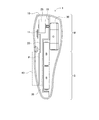
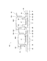
- 1 is an external perspective view of a tape printer according to an embodiment of the present invention. It is sectional drawing of a tape printer. It is explanatory drawing which shows the internal structure of a tape printer. It is explanatory drawing which shows the structure of the key input part which concerns on 1st Embodiment. It is explanatory drawing which shows the structure of the key input part which concerns on 2nd Embodiment. It is explanatory drawing which shows the structure of the key input part which concerns on 3rd Embodiment.
- the tape printer 1 is configured such that a user can perform desired text input, printing, etc. while holding the tape printer 1 with one hand.
- the tape printer 1 is composed of a main body mechanism part M and a grip part G.
- the main body mechanism part M constitutes an upper part in the longitudinal direction of the tape printer 1 and is formed in a slightly round shape in horizontal view.
- the main body mechanism M accommodates a liquid crystal display 11, a thermal head 31, a control board 20, and the like which will be described later.
- the grip portion G is formed to be slightly narrower than the left-right width dimension of the main body mechanism portion M in a substantially lower half side portion of the main body housing 10 in the longitudinal direction.
- the gripping portion G is formed so that its thickness is gradually smaller than that of the main body mechanism portion M. Therefore, the tape printer 1 is configured so that the user can easily perform operations such as inputting a desired text and printing on the printing tape T while the user holds the grip portion G with one hand.
- the tape printer 1 includes a main body housing 10 made of synthetic resin and a back cover 15, and the main body mechanism portion M and the grip portion G are respectively provided in the main body housing 10. And a back cover 15.
- the main body housing 10 houses therein a liquid crystal display 11 and a key input unit 40 which is an example of an input device according to the present invention.
- the back cover 15 is a synthetic resin cover member that covers the entire back surface of the main body housing 10 (the surface opposite to the surface facing the user when the tape printer 1 is used). It is detachably attached to the back surface of the body 10.
- a liquid crystal display 11 is disposed at a substantially central portion of the main body mechanism portion M on the front surface portion of the main body mechanism portion M (that is, on the main body housing 10 side).
- the liquid crystal display 11 displays various information such as an input result by the key input unit 40.
- the cutter lever 12 is provided in the left side part of the main body housing
- the cutter lever 12 slides the cutting blade 13 disposed inside the main body mechanism M in accordance with the turning operation. Therefore, the user can cut the printing tape T extending to the tape discharge port 14 to be described later with the cutting blade 13 by rotating the cutter lever 12 (see FIG. 3).
- control board 20 and a drive motor 25 are disposed inside the main body casing 10 constituting the main body mechanism section M.
- the control board 20 has a control circuit unit including a CPU, a ROM, a RAM, and the like.
- the control circuit unit plays a central role in various controls in the tape printer 1 and controls the tape printer 1 by executing a known control program or the like.
- the drive motor 25 is a drive source for transporting the printing tape T, which is a recording medium in the tape printer 1, to the tape discharge port 14.
- a cassette housing portion 30 is formed on the back side of the main body casing 10 constituting the main body mechanism portion M.
- the cassette housing portion 30 is formed in a substantially square shape with a horizontal section that is substantially the same as the outer shape of the tape cassette C, and is configured to be detachable from the tape cassette C (see FIG. 3).
- the tape cassette C incorporates a printing tape T that is a recording medium in the tape printer 1.
- the printing tape T is composed of an image receiving paper having a printing surface on which one surface is printed and an adhesive layer on the other surface, and a release paper that protects the adhesive layer.
- a thermal head 31 is erected on the bottom surface in the vicinity of the edge portion on the cutter lever 12 side so as to be along the longitudinal direction of the main body housing 10 inside the cassette housing portion 30.
- the thermal head 31 has a plurality of heating elements (for example, 64 heating elements) arranged in a row, and controls the heat generation of each heating element (not shown), thereby printing tape T Characters etc. are printed on.
- a platen holder 32 is disposed at a position facing the heating element disposition surface of the thermal head 31 so as to be rotatable about a rotation axis.
- the platen holder 32 presses the printing surface of the printing tape T against each heating element of the thermal head 31 when performing printing on the printing tape T.
- a key input unit 40 corresponding to the input device according to the present invention is disposed on the front surface of the gripper G (that is, the main body housing 10 side).
- the key input unit 40 includes a plurality of input keys such as a character input key, a space key, a cursor key, a power key, and a print key arranged in a matrix.
- Various types of keys for the control circuit unit of the tape printer 1 are provided. Used to input instructions. The configuration of the key input unit 40 will be described in detail later with reference to the drawings.
- the character input key is operated when inputting characters constituting the text to be printed.
- the space key is operated when a blank is entered in the text.
- the cursor key is operated when moving the cursor displayed on the liquid crystal display 11 to the left and right.
- the power key is operated when switching on / off the power supply to the tape printer 1.
- the print key is operated when the input text is printed on the print tape T by the thermal head 31.
- a battery storage unit 35 (see FIG. 3) is formed on the back side of the main body housing 10 constituting the grip unit G.
- the battery storage unit 35 stores a dry battery B which is a driving power source of the tape printer 1.
- the key input unit 40 includes a printed circuit board P and a rubber key member 45.
- the portion where the key input unit 40 is disposed (that is, the front surface side of the grip portion G) is formed in a curved shape that bulges outward from the main body housing 10 (see FIG. 2).
- the arrangement part of the key input unit 40 has a curved shape in which the upper end side of the gripping part G (the main body mechanism part M side) bulges to the front side from the lower end side of the gripping part G.
- a plurality of insertion holes 10 ⁇ / b> A are formed in the arrangement portion of the key input unit 40 by drilling the front side of the main body housing 10 according to the arrangement position of each input key.
- the printed circuit board P is a circuit board having a plurality of electrodes E on one side, and is disposed inside the main body housing 10 so as to correspond to the portion where the key input unit 40 is disposed.
- Each electrode E is formed on the surface of the printed circuit board P so as to correspond to the position where each input key is disposed (that is, below the insertion hole 10A).
- the surface of the printed board P on which the plurality of electrodes E are formed is referred to as an “electrode formation surface”.
- the rubber key member 45 is formed of a resin such as soft rubber, and is placed on the electrode formation surface of the printed circuit board P.
- the rubber key member 45 integrally includes a key top portion 46, a skirt portion 48, and a base portion 49.
- the key top portion 46 is a portion that is pressed by the user when performing an input operation of each input key, and is formed into a column shape having the same horizontal sectional shape by a resin such as soft rubber. Is formed.
- Each key top portion 46 is inserted through each insertion hole 10 ⁇ / b> A and is located on the electrode E on the printed circuit board P.
- Each key top portion 46 has a contact portion 47 on a surface facing the electrode E on the printed circuit board P. The contact portion 47 is formed by projecting a part of the surface on the printed board P side of the key top portion 46 toward the printed board P (that is, the electrode E) side by a predetermined amount.
- the contact portion 47 comes into contact with the electrode E formed on the surface of the printed circuit board P when the key top portion 46 moves in the direction of the printed circuit board P in accordance with the input operation of the input key. That is, in the tape printer 1, the input operation of the input key related to the key top portion 46 has been performed based on energization due to the contact between the contact portion 47 of the key top portion 46 and the electrode E of the printed circuit board P. Can be detected and control based on this can be performed.
- the skirt portion 48 is formed of a thin film-like soft rubber, and connects the outer peripheral edge at the lower end of the key top portion 46 and the upper surface of the base portion 49 (that is, the surface on the main body housing 10 side) (FIG. 4). reference). That is, the skirt portion 48 is formed of a thin-film-like soft rubber in a tapered cylindrical shape having a small outer peripheral edge at the lower end of the key top portion 46 and a large diameter at a connection portion with the base portion 49. When the input operation of the input key is performed, the skirt portion 48 is elastically deformed as the key top portion 46 moves in the direction of the printed circuit board P.
- the skirt portion 48 has an upper portion of the key top portion 46 (the top surface side of the key top portion 46) away from the insertion hole 10A.
- the key top portion 46 is supported so as to protrude quantitatively.
- the base portion 49 is formed in a plate shape with soft rubber or the like, and is placed on the electrode forming surface of the printed board P.
- the base portions 49 each have a step portion 50 around a predetermined key top portion 46 (see FIG. 4). Therefore, the upper surface of the base portion 49 around the key top portion 46 is positioned at different heights from the surface of the printed circuit board P due to the step portion 50.
- FIG. 4 is an XX cross-sectional view showing the configuration of the key input unit 40 in the tape printer 1 according to the first embodiment.
- the XX section is a section along the longitudinal direction of the tape printer 1.
- the input keys key top portions 46
- three input keys first key top portions 46A to 46A to 46A
- the configuration of the key input unit 40 will be described using the third key top portion 46C) as an example (see FIGS. 1 and 4).
- the first key top portion 46A to the third key top portion 46C are arranged in the order of the first key top portion 46A, the second key top portion 46B, and the third key top portion 46C from the lower end side of the grip portion G in the XX cross section. It is lined up along.
- the first key top portion 46A is formed in a column shape having a first key top height HA from a resin such as soft rubber, and is inserted through the insertion hole 10A.
- the first key top height HA means “the height from the connection portion with the skirt portion 48 at the outer peripheral edge of the first key top portion 46A to the top surface of the first key top portion 46A”.
- the base portion 49 is formed to have a thickness of the first base thickness DA.
- the contact portion 47 related to the first key top portion 46A projects a part of the surface of the first key top portion 46A on the printed circuit board P side by a predetermined amount toward the printed circuit board P (that is, the electrode E) side. Is formed.
- the surface of the contact portion 47 related to the first key top portion 46A is usually located at a position separated from the electrode E located below the first key top portion 46A by the first contact distance LA.
- the first contact distance LA means “a distance from the surface of the contact portion 47 of the first key top portion 46A to the electrode E positioned below the surface”.
- the second key top portion 46B is formed in a column shape having a second key top height HB from a resin such as soft rubber, and is inserted through the insertion hole 10A.
- the second key top height HB means “the height from the connecting portion of the skirt portion 48 to the top surface of the second key top portion 46B at the outer periphery of the lower end of the second key top portion 46B”. It shows the same height as the top portion 46A.
- the second key top portion 46B has the same horizontal cross-sectional shape as the first key top portion 46A described above. Accordingly, the second key top portion 46B has the same shape as the first key top portion 46A except for the configuration of the contact portion 47.
- the contact portion 47 related to the second key top portion 46B projects a part of the surface of the second key top portion 46B on the printed circuit board P side by a predetermined amount toward the printed circuit board P (that is, the electrode E). Is formed.
- the surface of the contact portion 47 related to the second key top portion 46B is usually located at a position separated from the electrode E positioned below the second key top portion 46B by the second contact distance LB.
- the second contact distance LB means “a distance from the surface of the contact portion 47 of the second key top portion 46B to the electrode E positioned below the second contact top portion 46B”, and indicates the same distance as the first contact distance LA.
- a stepped portion 50 is formed around the second key top portion 46B.
- the step portion 50 around the second key top portion 46B is formed by setting the thickness of the base portion 49 to a second base thickness DB larger than the first base thickness DA. Accordingly, the upper surface of the base portion 49 in the vicinity of the second key top portion 46B is a predetermined amount (that is, the second base thickness DB ⁇ the first base thickness DA) than the upper surface of the base portion 49 in the vicinity of the first key top portion 46A. It is located higher by the minute.
- the third key top portion 46C is formed in a column shape having a third key top height HC from a resin such as soft rubber, and is inserted into the insertion hole 10A.
- the third key top height HC means “the height from the connecting portion of the skirt portion 48 to the top surface of the third key top portion 46C at the outer periphery of the lower end of the third key top portion 46C”. It shows the same height as the top part 46A and the second key top part 46B.
- the third key top portion 46C has the same horizontal cross-sectional shape as the first key top portion 46A and the second key top portion 46B described above. Accordingly, the third key top portion 46C has the same shape as the first key top portion 46A and the second key top portion 46B, except for the configuration of the contact portion 47.
- the contact portion 47 related to the third key top portion 46C projects a part of the surface of the second key top portion 46B on the printed circuit board P side by a predetermined amount toward the printed circuit board P (that is, the electrode E). Is formed.
- the surface of the contact portion 47 related to the third key top portion 46C is usually located at a position separated from the electrode E located below the third key top portion 46C by the third contact distance LC.
- the third contact distance LC means “a distance from the surface of the contact portion 47 of the third key top portion 46C to the electrode E positioned below it”, and is the same as the first contact distance LA and the second contact distance LB. Indicates distance.
- a step 50 is formed around the third key top portion 46C in the same manner as the second key top portion 46B (see FIG. 4).
- the step portion 50 around the third key top portion 46C is formed by setting the thickness of the base portion 49 to a third base thickness DC that is larger than the first base thickness DA and the second base thickness DB. . Accordingly, the upper surface of the base portion 49 around the third key top portion 46C is positioned higher than the upper surface of the base portion 49 around the first key top portion 46A and the second key top portion 46B.
- the key input unit 40 is disposed on the front side of the grip unit G.
- the main body housing 10 has a curved surface in which the upper end side of the gripping part G (the main body mechanism part M side) bulges to the front side from the lower end side of the gripping part G.
- the printed circuit board P has a flat plate shape and is disposed inside the main body housing 10. Therefore, as shown in FIGS. 2 and 4, the distance from the surface of the printed circuit board P (that is, the electrode formation surface) to the front surface of the main body housing 10 (for example, the insertion hole 10 ⁇ / b> A) increases toward the main body mechanism M side.
- the base unit 49 has a thickness of the first base thickness DA to the third base thickness DC around the first key top unit 46A to the third key top unit 46C, respectively. It is formed with. Since the first base thickness DA, the second base thickness DB, and the third base thickness DC are larger in this order, the base portion 49 has a stepped portion 50.
- the base portion 49 around the first key top portion 46A to the third key top portion 46C is located on the basis of the electrode formation surface of the printed circuit board P as the periphery of the key top portion 46 located on the main body mechanism portion M side by the stepped portion 50. It is located at a high position (see FIG. 4).
- the first key top portion 46A, the second key top portion 46B, the third key top height HC has the same height with respect to the height from the connection portion of the skirt portion 48 to the top surface of the key top portion 46 at the outer periphery of the lower end of the key top portion 46.
- the skirt portions 48 that support the key top portions 46 are all formed in the same shape. Accordingly, the skirt portions 48 have the same height in any of the first key top portion 46A to the third key top portion 46C.
- the height of the top surface of the first key top portion 46A to the third key top portion 46C depends on the thickness of the base portion 49 around each key top portion 46, and is different in height. As shown in FIG. 4, since the thickness increases in the order of the first base thickness DA to the third base thickness DC, the height from the electrode formation surface of the printed circuit board P to the top surface of the key top portion 46 is The first key top portion 46A, the second key top portion 46B, and the third key top portion 46C are arranged in a higher order in this order.
- the first base thickness DA, the second base thickness DB, and the third base thickness DC are distances from the surface of the electrode E related to the corresponding key top portion 46 to the insertion hole 10A.
- the first key top portion 46A, the second key top portion 46B, and the third key top portion 46C are all disposed in a state of protruding by a predetermined amount from the respective insertion holes 10A. obtain.
- each key top portion 46 is supported by the skirt portion 48, the mass of each key top portion 46 acts on the skirt portion 48, and the skirt portion 48 of the skirt portion 48 at the time of an input operation to the input key. Affects elastic deformation. That is, the mass of each key top portion 46 affects the behavior of the key top portion 46 during an input operation.
- the first key top portion 46A, the second key top portion 46B, and the third key top portion 46C are all formed in a column shape from soft rubber, and have the same height dimension and the same horizontal level. It has a cross-sectional shape. Accordingly, the first key top portion 46A, the second key top portion 46B, and the third key top portion 46C all have substantially the same mass. Accordingly, in the tape printer 1, the masses of the first key top portion 46A to the third key top portion 46C have the same influence on the elastic deformation of the skirt portion 48, respectively.
- the portion 46A to the third key top portion 46C exhibit a substantially constant behavior in accordance with the input operation.
- the key top portion 46 is connected to the base portion 49 by a skirt portion 48 formed on the outer peripheral edge of the lower end of the key top portion 46, the key top portion 46 is within a certain range with the connection portion with the skirt portion 48 as an axis. Can be swung. Therefore, the top surface of the key top portion 46 can be positioned in a wider range as the dimension of the connection portion (the outer peripheral edge at the lower end of the key top portion 46) between the top surface of the key top portion 46 and the skirt portion 48 is larger.
- the key top portion 46 is easy to move in the direction connecting the connection portion between the current position and the skirt portion 48.
- the moving direction of the key top portion 46 in accordance with the input operation is such that the larger the dimension between the top surface of the key top portion 46 and the skirt portion 48 (the outer peripheral edge at the lower end of the key top portion 46) is, Deviation can occur.
- the first key top portion 46A to the third key top portion 46C are all dimensioned from the top surface of the key top portion 46 to the connection portion with the skirt portion 48 (that is, the first key top height HA to the second key top portion 46C).
- 3 key top high HC is the same. Therefore, according to the tape printer 1 according to the first embodiment, if any input key having a different height from the electrode forming surface to the top surface of the key top portion 46 is operated in the same manner as other input keys.
- the contact portion 47 and the electrode E are in contact with each other, and an input operation can be performed.
- the distances from the contact portions 47 to the electrodes E are the first contact distance LA, the second contact distance LB, the third It is the contact distance LC and shows the same dimension.
- the first contact distance LA to the third contact distance LC mean the amount of movement in the direction of the electrode E necessary to complete the input operation in the first key top portion 46A to the third key top portion 46C. Therefore, according to the tape printer 1 according to the first embodiment, any input key having a different height from the electrode forming surface to the top surface of the key top portion 46 is operated to move in the same manner as other input keys. By doing so, the contact portion 47 and the electrode E are in contact with each other, and an input operation can be performed.
- the stepped portion 50 has a thickness of the flat plate-like base portion 49 according to the arrangement position of each key top portion 46 (first base thickness DA, second base thickness DB, first thickness 3 base thickness DC). Accordingly, in the first embodiment, when the rubber key member 45 is manufactured, if the resin such as soft rubber is put in a predetermined mold and manufactured, the step portion is formed together with the key top portion 46, the skirt portion 48, and the base portion 49. 50 can be formed.
- the basic configuration of the tape printer 1 is the same as that of the first embodiment, and only the configuration of the key input unit 40 is different. Therefore, a description of the basic configuration of the tape printer 1 is omitted, and the configuration of the key input unit 40 according to the second embodiment will be described in detail.
- FIG. 5 is a sectional view taken along line XX showing the configuration of the key input unit 40 in the tape printer 1 according to the second embodiment.
- the input keys (keys) arranged in a matrix are shown.
- the configuration of the key input unit 40 is illustrated by exemplifying three input keys (first key top unit 46A to third key top unit 46C) arranged along the XX cross section in the top unit 46). This will be described (see FIGS. 1 and 5).
- the first key top portion 46A to the third key top portion 46C are arranged in the order of the first key top portion 46A, the second key top portion 46B, and the third key top portion 46C from the lower end side of the grip portion G in the XX cross section. It is lined up along.
- the key input unit 40 includes a printed circuit board P, a rubber key member 45, and a filling member 55.
- the printed circuit board P according to the second embodiment is a board having an electrode formation surface on which electrodes E corresponding to the positions of the input keys are formed, as in the first embodiment described above.
- the rubber key member 45 includes a key top portion 46, a skirt portion 48, and a base portion 49.
- the configurations of the key top portion 46 and the skirt portion 48 are the same as those in the first embodiment described above, and have already been described.
- the base portion 49 is formed of a soft rubber or the like as in the first embodiment, and is configured by a plate-like member having a predetermined thickness. As shown in FIG. 5, in the portion where the step portion 50 is formed, the base portion 49 is formed in a step shape while maintaining a predetermined thickness. Accordingly, the base portion 49 has a space below the portion where the step portion 50 is formed (that is, the peripheral portion of the predetermined key top portion 46).
- the filling member 55 is constituted by a member different from the rubber key member 45 and fills a space formed below the base portion 49 related to the step portion 50. Therefore, in the second embodiment, the stepped portion 50 around the second key top portion 46B is formed by the base portion 49 and the filling member 55 with a thickness of the second base thickness DB, and the third key top. The step portion 50 around the portion 46C is formed by the base portion 49 and the filling member 55 so as to have a third base thickness DC (see FIG. 5).
- the first key top portion 46A to the third key top portion 46C have the same height (that is, the first key top height HA to the third key top height HC). However, it is supported by the skirt portion 48 having the same shape. Therefore, also in the second embodiment, the height of the top surface of the first key top portion 46A to the third key top portion 46C depends on the thickness of the stepped portion 50 around each key top portion 46, and has a different height. It becomes. As shown in FIG.
- the height from the electrode formation surface of the printed circuit board P to the top surface of the key top portion 46 is The first key top portion 46A, the second key top portion 46B, and the third key top portion 46C are arranged in a higher order in this order.
- the first base thickness DA, the second base thickness DB, and the third base thickness DC are distances from the surface of the electrode E related to the corresponding key top portion 46 to the insertion hole 10A.
- the first key top portion 46A, the second key top portion 46B, and the third key top portion 46C are all disposed in a state of protruding by a predetermined amount from the respective insertion holes 10A. obtain.
- the first key top portion 46A, the second key top portion 46B, and the third key top portion 46C are all formed in a column shape from soft rubber and have the same height dimension. Are configured with the same horizontal cross-sectional shape, and are formed with substantially the same mass. Accordingly, in the tape printer 1, the masses of the first key top portion 46A to the third key top portion 46C have the same influence on the elastic deformation of the skirt portion 48, respectively.
- the portion 46A to the third key top portion 46C exhibit a substantially constant behavior in accordance with the input operation.
- first key top portion 46A to the third key top portion 46C according to the second embodiment all have dimensions from the top surface of the key top portion 46 to the connection portion with the skirt portion 48 (that is, the first key top portion).
- High HA to third key top high HC) are the same. Therefore, according to the tape printer 1 according to the second embodiment, if any input key having a different height from the electrode forming surface to the top surface of the key top portion 46 is operated in the same manner as the other input keys.
- the contact portion 47 and the electrode E are in contact with each other, and an input operation can be performed.
- the distance from each contact portion 47 to the electrode E is the first contact distance LA, the second key top portion 46C.
- the contact distance LB and the third contact distance LC indicate the same dimensions. Therefore, according to the tape printer 1 according to the second embodiment, any input key having a different height from the electrode formation surface to the top surface of the key top portion 46 is operated to move in the same manner as other input keys. By doing so, the contact portion 47 and the electrode E are in contact with each other, and an input operation can be performed.
- the basic configuration of the tape printer 1 is the same as that of the first embodiment and the second embodiment, and only the configuration of the key input unit 40 is different. Therefore, description of the basic configuration of the tape printer 1 is omitted, and the configuration of the key input unit 40 according to the third embodiment will be described in detail.
- FIG. 6 is an XX cross-sectional view showing the configuration of the key input unit 40 in the tape printer 1 according to the third embodiment. Similarly to FIGS. 4 and 5, each input arranged in a matrix is shown. Of the keys (key top part 46), two input keys (first key top part 46A, second key top part 46B) arranged along the XX cross section are exemplified, and the key input part 40 (See FIGS. 1 and 6). The first key top portion 46A is arranged in a line at the lower end side of the grip portion G with respect to the second key top portion 46B along the XX cross section.
- the key input unit 40 according to the third embodiment includes a printed circuit board P and a rubber key member 45.
- the printed circuit board P according to the third embodiment is a substrate having an electrode formation surface on which electrodes E corresponding to the arrangement positions of the input keys are formed, as in the first and second embodiments described above.
- the rubber key member 45 according to the third embodiment includes a key top portion 46, a skirt portion 48, and a base portion 49.
- the first key top portion 46A is formed in a column shape having a first key top height HA by a resin such as soft rubber, and is inserted through the insertion hole 10A (see FIG. 6).
- the base portion 49 is formed to have a thickness of the first base thickness DA.
- the second key top portion 46B is formed in a column shape having a second key top height HB from a resin such as soft rubber, and is inserted through the insertion hole 10A.
- the horizontal cross-sectional shape of the second key top portion 46B is the same as that of the first key top portion 46A described above.
- the second key top height HB is larger than the first key top height HA in the first key top portion 46A, as shown in FIG.
- the base portion 49 around the second key top portion 46B according to the third embodiment has a thickness of the second base thickness DB, and the second base thickness DB is around the first key top portion 46A. Is the same as the base thickness (that is, the first base thickness DA).
- the skirt portions 48 that support the key top portions 46 are all formed in the same shape. Therefore, the heights of the skirt portions 48 are the same in both the first key top portion 46A and the second key top portion 46B. That is, in the first key top portion 46A and the second key top portion 46B according to the third embodiment, the base portion 49 has the same thickness and the skirt portion 48 has the same height.
- the top surface of the top portion 46B is positioned at a position higher than the top surface of the first key top portion 46A by an amount corresponding to “the difference between the second key top height HB and the first key top height HA”.
- the key input unit 40 is disposed on the front side of the gripping part G, and the main body housing 10 relating to the disposed part is on the gripping part G upper end side (main body mechanism part M side). Forms a curved surface that bulges to the front side rather than the lower end side of the grip portion G.
- the printed circuit board P has a flat plate shape and is disposed inside the main body housing 10. Therefore, as shown in FIGS. 2, 4, and 5, the distance from the surface of the printed circuit board P (that is, the electrode forming surface) to the front surface of the main body housing 10 (for example, the insertion hole 10A) is closer to the main body mechanism portion M side. growing.
- the first key top height HA and the second key top height HB are distances from the surface of the electrode E related to the corresponding key top portion 46 to the insertion hole 10A.
- the first key top portion 46A and the second key top portion 46B can be disposed in a state of protruding by a certain amount from the respective insertion holes 10A.
- the contact portion 47 related to the first key top portion 46A has a part of the surface on the printed board P side of the first key top portion 46A located on the printed board P (ie, electrode E) side. It is formed by protruding a certain amount.
- the surface of the contact portion 47 related to the first key top portion 46A is usually located at a position separated from the electrode E located below the first key top portion 46A by the first contact distance LA.
- the contact portion 47 related to the second key top portion 46B projects a part of the surface of the second key top portion 46B on the printed board P side by a predetermined amount toward the printed board P (that is, the electrode E). Is formed.
- the surface of the contact portion 47 related to the second key top portion 46B is usually located at a position separated from the electrode E positioned below the second key top portion 46B by the second contact distance LB.
- the protrusion amount of the contact portion 47 related to the second key top portion 46B is the protrusion amount of the contact portion 47 related to the first key top portion 46A by the difference value between the first key top height HA and the second key top height HB. The value is larger than the amount. Accordingly, the second contact distance LB indicates the same distance as the first contact distance LA.
- the 2nd key top part 46B which concerns on 3rd Embodiment has the thickness reduction part 60 around the contact part 47.
- the lightening part 60 is configured by reducing the resin constituting the second key top part 46B and forming a space around the contact part 47 of the second key top part 46B.
- the space constituting the lightening portion 60 corresponds to a volume that increases when the first key top portion 46A according to the third embodiment is set to the second key top height HB. Since the first key top part 46A and the second key top part 46B are both made of the same resin, the second key top part 46B has the same mass as the first key top part 46A.
- each key top portion 46 is supported by the skirt portion 48, the mass of each key top portion 46 acts on the skirt portion 48, and the skirt portion 48 of the skirt portion 48 at the time of an input operation to the input key. Affects elastic deformation. Therefore, in the tape printer 1 according to the third embodiment, the masses of the first key top portion 46A and the second key top portion 46B have the same influence on the elastic deformation of the skirt portion 48, respectively. Since both the first key top portion 46A and the second key top portion 46B have the same mass, the first key top portion 46A and the second key top portion 46B are substantially constant with the input operation. If any of the input keys having different heights from the electrode formation surface to the top surface of the key top portion 46 is operated in the same manner as the other input keys, the contact portion 47 and the electrode E come into contact with each other. , Accurate input operation can be performed.
- the distances from the respective contact portions 47 to the electrode E are the first contact distance LA and the second contact distance LB, which are the same. Show dimensions.
- the first contact distance LA and the second contact distance LB mean the amount of movement in the direction of the electrode E necessary to complete the input operation at the first key top portion 46A and the second key top portion 46B. Therefore, according to the tape printer 1 according to the third embodiment, any input key having a different height from the electrode formation surface to the top surface of the key top portion 46 is operated to move in the same manner as other input keys. By doing so, the contact portion 47 and the electrode E are in contact with each other, and an input operation can be performed.
- the present invention has been described above based on the embodiments. However, the present invention is not limited to the above-described embodiments, and various improvements and modifications can be made without departing from the spirit of the present invention.
- the input key portions arranged along the longitudinal direction of the tape printer 1 are illustrated, but the present invention is not limited to this aspect. That is, it goes without saying that the present invention can be applied to input key portions arranged along the short direction of the tape printer 1.
- the configuration of the lightening portion 60 according to the third embodiment is not limited to the example shown in FIG. That is, if the mass of the second key top portion 46B can be made the same as the mass of the first key top portion 46A by forming a space in the second key top portion 46B, the lightening portion 60 can be changed to various types. It can be a shape.
Landscapes
- Push-Button Switches (AREA)
Abstract
プリント基板と、ベース部、キートップ部、スカート部を有するラバーキー部材とを有する入力装置に関し、天面までの高さが異なる複数のキートップ部を有し、入力操作の誤認識を防止可能な入力装置を提供する。 テープ印字装置1は、ラバーキー部材45と、電極形成面を有するプリント基板Pにより構成されるキー入力部40を、本体筐体10の曲面部分に有している。ラバーキー部材45は、キートップ部46と、スカート部48と、ベース部49により構成され、プリント基板Pの電極形成面上に載置される。各キートップ部46は、当該キートップ部46下端のスカート部48との接続部分から天面までの高さを等しく形成されている。各キートップ部46周囲に位置するベース部49を、本体筐体10の曲面部分に対応する厚みで構成することにより、各キートップ部46の天面は、前記曲面部分から所定量突出する高さに位置する。
Description
本発明は、プリント基板と、ベース部、キートップ部、スカート部を有するラバーキー部材とを有する入力装置に関する。
従来、入力装置は、種々の入力操作に用いられる複数の入力キーを有しており、筐体に形成されたキー配置部に配設されている。そして、これらの入力装置の一態様として、プリント基板と、ラバーキー部材により構成される入力装置が知られている。例えば、特許文献1に記載の入力装置では、ラバーキー部材は、各入力キーを構成するキートップ部と、平板状のベース部と、キートップ部の下端外周縁に形成された薄膜状のスカート部とを、合成樹脂により一体的に有しており、プリント基板上に載置される。
当該入力装置では、キートップ部の押下操作が行われると、当該キートップ部は、その周囲のスカート部を変形しつつ、プリント基板表面に向かって移動する。これにより、当該キートップ部の接点は、プリント基板表面に形成された電極と接触することとなり、もって、当該キートップ部に係る入力操作に係る制御信号を出力し得る。従って、キートップ部の押下操作が行われる関係上、キートップ部の上部は、キー配置部を構成する筐体表面から突出していることが望ましい。キートップ部を押下する力から解放されると、キートップ部は、スカート部の弾性力に基づいて、通常の位置に戻るように構成されている。
ここで、筐体に形成されたキー配置部は、平板状に形成された部分に限らず、曲面状に形成されている場合もある。そして、この場合であっても、キートップ部の上部は、キー配置部を構成する筐体表面から所定寸法突出していることが望ましい。即ち、曲面状の筐体表面から所定寸法突出するように構成するため、キートップ部の天面高さは、曲面状の筐体表面における位置に応じて異ならなければならない。
天面高さの異なるキートップ部を有する入力装置として、特許文献2記載の発明が知られており、携帯電話機に係る入力装置として、キーパッド組立体が記載されている。当該キーパッド組立体は、平板状のベース部と共に、複数のキートップが合成樹脂により一体的に形成されて構成されている。そして、当該キーパッド組立体においては、ベース部から立設されるキートップ部の高さを相違させることにより、キートップ部の天面高さが異なる態様を実現している。尚、特許文献2記載のキーパッド組立体においては、キートップ部とベース部の間に、薄膜状のスカート部は形成されていない。
ここで、特許文献1のように、ベース部、キートップ部、スカート部を有するラバーキー部材と、プリント基板を有する入力装置において、キートップ部の天面高さを相違させるために、特許文献2の構成を用いた場合について考察する。上述したように、特許文献2では、キートップ部の高さを相違させることにより、キートップ部の天面高さを相違させているので、キートップ部の質量は、当該キートップ部の高さ寸法に応じて相違することになる。
そして、各キートップ部は、薄膜状のスカート部により、ベース部に対して押下操作可能に支持されているので、スカート部にかかる荷重は、キートップ部の高さ寸法に応じて相違する。スカート部にかかる荷重は、キートップ部の押下操作に伴うスカート部の変形態様に大きな影響を与えるため、押下操作に伴うキートップ部の挙動は、キートップ部の高さ寸法に応じて相違することになる。この結果、当該構成を有する入力装置は、押下操作に伴うキートップ部の挙動が相違してしまうため、ユーザによる入力操作の誤認識の要因となってしまう。又、当該構成を有する入力装置は、押下操作に伴うキートップ部の挙動の相違によって、キートップ部の押下操作時に、ユーザに違和感を与えてしまう。
本発明は、上記問題点を解決するためになされたものであり、プリント基板と、ベース部、キートップ部、スカート部を有するラバーキー部材とを有する入力装置に関し、天面までの高さが異なる複数のキートップ部を有し、入力操作の誤認識を防止可能な入力装置を提供することを目的とする。
本発明の一側面に係る入力装置は、複数の電極を有する平板状のプリント基板と、前記プリント基板表面に配設されるベース部と、前記複数の電極の上方に位置し、前記ベース部の上方へ突出した複数のキートップ部と、前記各キートップ部の下端外周縁と前記ベース部を接続する薄膜状のスカート部と、を合成樹脂により一体に形成されたラバーキー部材と、を有する入力装置であって、前記ラバーキー部材は、前記キートップ部を前記プリント基板方向へ移動した場合に前記電極と接触する接点部を、前記プリント基板と対向する面に備え、前記スカート部と前記ベース部との接続部分から前記キートップ部の天面までの高さが所定の第1寸法である第1キートップ部と、前記第1キートップ部の周囲に位置するベース部の高さよりも高く形成された段差部を周囲に備えると共に、前記プリント基板と対向する面に前記接点部を備え、前記スカート部と前記段差部との接続部分から前記キートップ部の天面までの高さが前記第1寸法である第2キートップ部と、を有し、前記第2キートップ部の天面は、前記第1キートップ部の天面よりも高い位置に位置することを特徴とする。
当該入力装置は、平板状のプリント基板と、ラバーキー部材とを有している。ラバーキー部材には、ベース部、複数のキートップ部、薄膜状のスカート部が合成樹脂により一体的に形成されており、プリント基板表面に配設される。従って、当該入力装置においては、キートップ部をプリント基板方向へ移動操作すると、当該キートップ部は、薄膜状に形成されたスカート部を変形させつつ移動し、プリント基板表面に形成された電極に対して、接点部を接触させ得る。又、当該入力装置において、ラバーキー部材は、第1キートップ部と、第2キートップ部を有している。第1キートップ部は、前記スカート部と前記ベース部との接続部分から前記キートップ部の天面までの高さが所定の第1寸法となるように形成されている。第2キートップ部は、スカート部と段差部との接続部分から前記キートップ部の天面までの高さが第1寸法となるように形成されており、第2キートップ部の周囲には、段差部が、第1キートップ部の周囲に位置するベース部の高さよりも高く形成されている。従って、第2キートップ部の天面は、段差部の存在により、前記第1キートップ部の天面よりも高い位置に位置する。又、当該入力装置において、第1キートップ部、第2キートップ部は、何れもキートップ部の天面までの高さが第1寸法に形成されている。従って、当該入力装置において、第1キートップ部の周囲のスカート部、第2キートップ部の周囲のスカート部の何れにも、略同等の荷重が加わることとなる。この結果、当該入力装置は、天面までの高さの異なるキートップ部であっても、スカート部に係る荷重の相違に基づく入力操作の誤認識を防止し得る。又、当該入力装置によれば、ユーザは、天面までの高さの異なるキートップ部であっても、違和感なく、これらのキーを操作し得る。
本発明の他の側面に係る入力装置は、請求項1に記載の入力装置であって、前記第2キートップ部の周囲における前記スカート部との接続部分から、前記第2キートップ部の天面までの高さは、前記第1キートップ部の周囲における前記スカート部との接続部分から、前記第1キートップ部の天面までの高さと等しいことを特徴とする。
当該入力装置において、第1キートップ部、第2キートップ部は、何れも、各キートップ部の周囲におけるスカート部との接続部分から、キートップ部の天面までの高さが等しく形成されている。従って、当該入力装置において、第1キートップ部の周囲のスカート部、第2キートップ部の周囲のスカート部の何れにも、同等の荷重が加わることとなる。この結果、当該入力装置は、天面までの高さの異なるキートップ部であっても、スカート部に係る荷重の相違に基づく入力操作の誤認識を防止し得る。又、当該入力装置によれば、ユーザは、天面までの高さの異なるキートップ部であっても、これらのキーを違和感なく操作し得る。
本発明の他の側面に係る入力装置は、請求項1又は請求項2に記載の入力装置であって、前記第2キートップ部の接点部と、当該第2キートップ部の下方の前記プリント基板上の電極の間の距離は、前記第1キートップ部の接点部と、当該第1キートップ部の下方の前記プリント基板上の電極の間の距離と等しいことを特徴とする。
当該入力装置では、第1キートップ部、第2キートップ部の何れにおいても、接点部とプリント基板上の電極との間の距離は、等しく形成されている。即ち、天面までの高さの異なるキートップ部であっても、入力操作に伴って接点部が電極に接触するまで移動する距離が等しくなる。これにより、当該入力装置によれば、ユーザは、天面までの高さの異なるキートップ部であっても、これらのキーを違和感なく操作し得る。
本発明の他の側面に係る入力装置は、請求項1乃至請求項3の何れかに記載の入力装置であって、装置外側に向かって突出した曲面状に形成されたキー配置部に、前記複数のキートップ部が夫々挿通される複数の挿通孔を有する本体筐体を備え、前記第2キートップ部は、前記第1キートップ部が挿通される挿通孔よりも、曲面状のキー配置部における突出部分寄りに位置する挿通孔を挿通することを特徴とする。
当該入力装置は、装置外側に向かって突出した曲面状に形成されたキー配置部に、前記複数のキートップ部が夫々挿通される複数の挿通孔を有する本体筐体を備えている。そして、当該入力装置において、前記第2キートップ部は、前記第1キートップ部が挿通される挿通孔よりも、曲面状のキー配置部における突出部分寄りに位置する挿通孔を挿通している。即ち、当該入力装置は、曲面状に形成されたキー配置部において、何れのキートップ部についても、本体筐体表面を基準として一定量突出した状態にし得る。
本発明の他の側面に係る入力装置は、請求項1乃至請求項4の何れかに記載の入力装置であって、前記段差部は、前記第2キートップ部の周囲に位置するベース部の厚みを、前記第1キートップ部の周囲に位置するベース部の厚みよりも大きくすると共に、前記第1キートップ部の周囲に位置するベース部と一体に形成することで構成されていることを特徴とする。
当該入力装置において、段差部は、第2キートップ部の周囲に位置するベース部の厚みを、前記第1キートップ部の周囲に位置するベース部の厚みよりも大きくすると共に、前記第1キートップ部の周囲に位置するベース部と一体に形成することで構成されている。従って、当該構成により段差部を形成することにより、当該入力装置は、第1キートップ部の天面高さと、第2キートップ部の天面高さを、確実に異ならせることができる。
本発明の他の側面に係る入力装置は、請求項1乃至請求項4の何れかに記載の入力装置であって、前記段差部は、前記第2キートップ部の周囲に位置するベース部表面を、前記第1キートップ部の周囲に位置するベース部表面より上方に突出させると共に、下方に所定の空間を形成する段差形成部と、前記段差形成部により形成された空間内に配設され、当該空間を充填する充填部材と、により構成されていることを特徴とする。
当該入力装置において、前記段差部は、前記第2キートップ部の周囲に位置するベース部表面を、前記第1キートップ部の周囲に位置するベース部表面より上方に突出させると共に、下方に所定の空間を形成する段差形成部と、前記段差形成部により形成された空間内に配設され、当該空間を充填する充填部材と、により構成されている。即ち、当該入力装置は、段差形成部と充填部材により段差部を形成するで、第1キートップ部の天面高さと、第2キートップ部の天面高さを、確実に異ならせることができる。
又、本発明のもう一つの側面に係る入力装置は、複数の電極を有する平板状のプリント基板と、前記プリント基板表面に配設されるベース部と、前記複数の電極の上方に位置し、前記ベース部の上方へ突出した複数のキートップ部と、前記各キートップの下端外周縁と前記ベース部を接続する薄膜状のスカート部と、を合成樹脂により一体に形成されたラバーキー部材と、を有する入力装置であって、前記ラバーキー部材は、前記キートップ部を前記プリント基板方向へ移動した場合に前記電極と接触する接点部を、前記プリント基板と対向する面に備え、前記スカート部との接続部分から上方部分を所定の形状で形成した第1キートップ部と、前記プリント基板と対向する面に前記接点部を備え、前記スカート部との接続部分から上方部分を前記第1キートップ部の平面外形と同一形状であり、且つ、同一質量で形成した第2キートップ部と、を有し、前記第2キートップ部の天面は、前記第1キートップ部の天面よりも高い位置に位置することを特徴とする。
当該入力装置は、平板状のプリント基板と、ラバーキー部材とを有している。ラバーキー部材には、ベース部、複数のキートップ部、薄膜状のスカート部が合成樹脂により一体的に形成されており、プリント基板表面に配設される。従って、当該入力装置においては、キートップ部をプリント基板方向へ移動操作すると、当該キートップ部は、薄膜状に形成されたスカート部を変形させつつ移動し、プリント基板表面に形成された電極に対して、接点部を接触させ得る。又、当該入力装置において、ラバーキー部材は、第1キートップ部と、第2キートップ部を有している。第1キートップ部は、前記スカート部との接続部分から上方部分を所定の形状で形成されており、前記プリント基板と対向する面に、接点部を備えている。そして、第2キートップ部は、前記スカート部との接続部分から上方部分を前記第1キートップ部の平面外形と同一形状であり、且つ、同一質量で形成されており、前記プリント基板と対向する面に、接点部を備えている。又、第2キートップ部の天面は、前記第1キートップ部の天面よりも高い位置に位置する。又、当該入力装置において、第1キートップ部、第2キートップ部は、何れも平面外形と同一形状であり、且つ、同一質量で形成されているため、第1キートップ部の周囲のスカート部、第2キートップ部の周囲のスカート部の何れにも、略同等の荷重が加わることとなる。この結果、当該入力装置は、天面までの高さの異なるキートップ部であっても、スカート部に係る荷重の相違に基づく入力操作の誤認識を防止し得る。又、当該入力装置によれば、ユーザは、天面までの高さの異なるキートップ部であっても、違和感なく、これらのキーを操作し得る。
本発明の他の側面に係る入力装置は、請求項7に記載の入力装置であって、前記ベース部は、前記第1キートップ部の周囲に位置するベース部の高さよりも高く形成された段差部を、前記第2キートップ部の周囲に備えることにより、前記第2キートップ部の天面を、前記第1キートップ部の天面よりも高い位置に位置させることを特徴とする。
当該入力装置において、段差部は、第2キートップ部の周囲に位置するベース部の厚みを、前記第1キートップ部の周囲に位置するベース部の厚みよりも大きくすると共に、前記第1キートップ部の周囲に位置するベース部と一体に形成することで構成されている。従って、当該構成により段差部を形成することにより、当該入力装置は、第1キートップ部の天面高さと、第2キートップ部の天面高さを、確実に異ならせることができる。
本発明の他の側面に係る入力装置は、請求項8に記載の入力装置であって、前記第2キートップ部の周囲における前記スカート部との接続部分から、前記第2キートップ部の天面までの高さは、前記第1キートップ部の周囲における前記スカート部との接続部分から、前記第1キートップ部の天面までの高さと等しいことを特徴とする。
当該入力装置では、第1キートップ部、第2キートップ部は、何れも、各キートップ部の周囲におけるスカート部との接続部分から、キートップ部の天面までの高さが等しく形成されている。従って、当該入力装置において、第1キートップ部の周囲のスカート部、第2キートップ部の周囲のスカート部の高さが等しいこととなるため、第1キートップ部の天面高さと、第2キートップ部の天面高さを、確実に異ならせることができる。この結果、当該入力装置は、天面までの高さの異なるキートップ部であっても、スカート部に係る荷重の相違に基づく入力操作の誤認識を防止し得る。又、当該入力装置によれば、ユーザは、天面までの高さの異なるキートップ部であっても、これらのキーを違和感なく操作し得る。
本発明の他の側面に係る入力装置は、請求項7に記載の入力装置であって、前記第2キートップ部の周囲における前記スカート部との接続部分から、前記第2キートップ部の天面までの高さは、前記第1キートップ部の周囲における前記スカート部との接続部分から、前記第1キートップ部の天面までの高さよりも大きく形成され、前記第2キートップ部は、当該第2キートップ部の内側部分を、前記第1キートップ部の内側部分よりも減じた肉抜き部を有することにより、当該第2キートップ部における前記スカート部との接続部分から上方部分の質量を、前記第1キートップ部における前記スカート部との接続部分から上方部分の質量と等しく形成されていることを特徴とする。
当該入力装置において、前記第2キートップ部の周囲における前記スカート部との接続部分から、前記第2キートップ部の天面までの高さは、前記第1キートップ部の周囲における前記スカート部との接続部分から、前記第1キートップ部の天面までの高さよりも大きく形成されている。従って、当該入力装置によれば、第1キートップ部の天面高さと、第2キートップ部の天面高さを、確実に異ならせることができる。前記第2キートップ部は、前記スカート部との接続部分から上方部分を前記第1キートップ部の平面外形と同一形状で構成されており、当該第2キートップ部の内側部分を、前記第1キートップ部の内側部分よりも減じた肉抜き部を有している。従って、当該入力装置において、当該第2キートップ部における前記スカート部との接続部分から上方部分の質量は、前記第1キートップ部における前記スカート部との接続部分から上方部分の質量と等しくし得る。これにより、当該入力装置においては、第1キートップ部の周囲のスカート部、第2キートップ部の周囲のスカート部の何れにも、略同等の荷重が加わることとなるので、当該入力装置は、天面までの高さの異なるキートップ部であっても、スカート部に係る荷重の相違に基づく入力操作の誤認識を防止し得る。又、当該入力装置によれば、ユーザは、天面までの高さの異なるキートップ部であっても、違和感なく、これらのキーを操作し得る。
本発明の他の側面に係る入力装置は、請求項7乃至請求項10の何れかに記載の入力装置であって、前記第2キートップ部の接点部と、当該第2キートップ部の下方の前記プリント基板上の電極との間の距離は、前記第1キートップ部の接点部と、当該第1キートップ部の下方の前記プリント基板上の電極との間の距離と等しいことを特徴とする。
当該入力装置において、第1キートップ部、第2キートップ部の何れにおいても、接点部とプリント基板上の電極との間の距離は、等しく形成されている。即ち、天面までの高さの異なるキートップ部であっても、入力操作に伴って接点部が電極に接触するまで移動する距離が等しくなる。これにより、当該入力装置によれば、ユーザは、天面までの高さの異なるキートップ部であっても、これらのキーを違和感なく操作し得る。
本発明の他の側面に係る入力装置は、請求項7乃至請求項11の何れかに記載の入力装置であって、装置外側に向かって突出した曲面状に形成されたキー配置部に、前記複数のキートップ部が夫々挿通される複数の挿通孔を有する本体筐体を備え、前記第2キートップ部は、前記第1キートップ部が挿通される挿通孔よりも、曲面状のキー配置部における突出部分寄りに位置する挿通孔を挿通することを特徴とする。
当該入力装置は、装置外側に向かって突出した曲面状に形成されたキー配置部に、前記複数のキートップ部が夫々挿通される複数の挿通孔を有する本体筐体を備えている。そして、当該入力装置において、前記第2キートップ部は、前記第1キートップ部が挿通される挿通孔よりも、曲面状のキー配置部における突出部分寄りに位置する挿通孔を挿通している。即ち、当該入力装置は、曲面状に形成されたキー配置部において、何れのキートップ部についても、本体筐体表面を基準として一定量突出した状態にし得る。
(第1実施形態)
以下、本発明に係る入力装置を、テープ印字装置に具体化した一実施形態(第1実施形態)について図面を参照しつつ詳細に説明する。先ず、第1実施形態に係るテープ印字装置の概略構成について図1~図3に基づき説明する。当該テープ印字装置1は、ユーザが片手で当該テープ印字装置1を持ちながら、所望のテキスト入力や印刷等を行い得るように構成されている。
以下、本発明に係る入力装置を、テープ印字装置に具体化した一実施形態(第1実施形態)について図面を参照しつつ詳細に説明する。先ず、第1実施形態に係るテープ印字装置の概略構成について図1~図3に基づき説明する。当該テープ印字装置1は、ユーザが片手で当該テープ印字装置1を持ちながら、所望のテキスト入力や印刷等を行い得るように構成されている。
図1~図3に示すように、当該テープ印字装置1は、本体機構部Mと、把持部Gにより構成されている。本体機構部Mは、テープ印字装置1の長手方向において、上側部分を構成し、水平視やや丸く形成されている。本体機構部Mは、後述する液晶ディスプレイ11、サーマルヘッド31や制御基板20等を内部に収容している。
把持部Gは、本体筐体10の長手方向のほぼ下半分側の部分において、前記本体機構部Mの左右幅寸法よりも少し狭く形成されている。又、図2に示すように、把持部Gは、その厚みが本体機構部Mに比べてなだらかに小さくなるように形成されている。従って、当該テープ印字装置1は、当該把持部Gをユーザが片手で持ちながら、所望のテキストの入力や印字用テープTへの印刷等の操作を行い易いように構成されている。
又、図2に示すように、テープ印字装置1は、合成樹脂製の本体筐体10と、背面カバー15を有しており、本体機構部M及び把持部Gは、夫々、本体筐体10及び背面カバー15により構成されている。本体筐体10は、液晶ディスプレイ11や、本発明に係る入力装置の一例であるキー入力部40等を内部に収容している。そして、背面カバー15は、本体筐体10の背面部(テープ印字装置1を使用する際に使用者と対向する面と反対側の面)全体を覆う合成樹脂製のカバー部材であり、本体筐体10の背面に対して、着脱可能に取り付けられている。
本体機構部Mの前面部(即ち、本体筐体10側)には、液晶ディスプレイ11が、本体機構部Mの略中央部に配設されている。当該液晶ディスプレイ11は、キー入力部40による入力結果等の種々の情報を表示する。
そして、本体機構部Mを構成する本体筐体10の左側側面部には、カッターレバー12が、回動操作可能に設けられている。当該カッターレバー12は、その回動操作に伴って、本体機構部M内部に配設されている切断刃13をスライド移動させる。従って、ユーザは、当該カッターレバー12を回動操作することにより、後述するテープ排出口14へ延びる印字用テープTを切断刃13によって切断し得る(図3参照)。
更に、本体機構部Mを構成する本体筐体10内部には、制御基板20と、駆動モータ25が配設されている。当該制御基板20は、CPU、ROM、RAM等を含む制御回路部を有している。当該制御回路部は、テープ印字装置1における種々の制御の中枢を担い、公知の制御プログラム等を実行することにより、テープ印字装置1を制御する。そして、駆動モータ25は、テープ印字装置1における被記録媒体である印字用テープTを、テープ排出口14に搬送する際の駆動源である。
図2、図3に示すように、本体機構部Mを構成する本体筐体10の背面側には、カセット収納部30が形成されている。カセット収納部30は、テープカセットCの外形とほぼ同じ水平断面略四角形状に形成されており、テープカセットCを着脱可能に構成されている(図3参照)。そして、テープカセットCは、当該テープ印字装置1における被記録媒体である印字用テープTを内蔵している。当該印字用テープTは、一方の面に印刷が施される印刷面を有し、他方の面に接着層を有する受像紙と、前記接着層を保護する剥離紙により構成されている。
又、カセット収納部30の内部には、サーマルヘッド31が、本体筐体10の長手方向に沿うように、カッターレバー12側の端縁部近傍の底面に立設されている。当該サーマルヘッド31は、1列に配設された複数の発熱素子(例えば、64個の発熱素子)を有し、各発熱素子(図示せず)の発熱制御を行うことにより、印字用テープTに文字等の印字を行う。
図3に示すように、サーマルヘッド31の発熱素子配設面に対向する位置には、プラテンホルダ32が、回転軸を中心に回動自在に配設されている。当該プラテンホルダ32は、印字用テープTに対する印刷を行う際に、印字用テープTの印刷面を、サーマルヘッド31の各発熱素子に押圧する。
把持部Gの前面部(即ち、本体筐体10側)には、本発明に係る入力装置に相当するキー入力部40が配設されている。当該キー入力部40は、文字入力キー、スペースキー、カーソルキー、電源キー、印刷キー等の複数の入力キーをマトリクス状に配置して有しており、テープ印字装置1の制御回路部に対する種々の指示入力に用いられる。当該キー入力部40の構成については、後に図面を参照しつつ詳細に説明する。
尚、文字入力キーは、印刷対象であるテキストを構成するキャラクタを入力する際に操作される。スペースキーは、テキスト中に空白を入力する際に操作される。カーソルキーは、液晶ディスプレイ11上に表示されるカーソルを左右に移動させる際に操作される。電源キーは、テープ印字装置1に対する電源供給のオン・オフを切り替える際に操作される。印刷キーは、サーマルヘッド31により、入力されたテキストを印字用テープTに印刷する際に操作される。
そして、把持部Gを構成する本体筐体10の背面側には、電池収納部35(図3参照)が形成されている。当該電池収納部35は、テープ印字装置1の駆動電源である乾電池Bを収納する。
続いて、キー入力部40の構成について、図面を参照しつつ詳細に説明する。図4に示すように、キー入力部40は、プリント基板Pと、ラバーキー部材45により構成されている。尚、本体筐体10において、キー入力部40の配設部分(即ち、把持部G前面側)は、本体筐体10から外側方向に膨出した曲面形状に形成されている(図2参照)。即ち、キー入力部40の配設部分は、把持部G上端側(本体機構部M側)が把持部G下端側よりも前面側に膨出する曲面形状である。そして、キー入力部40の配設部分には、複数の挿通孔10Aが、各入力キーの配設位置に応じて、本体筐体10の前面側を穿設して形成されている。
プリント基板Pは、一面側に複数の電極Eを有する基板であり、本体筐体10の内部において、キー入力部40の配設部分に対応して配設されている。各電極Eは、プリント基板P表面において、各入力キーの配設位置(即ち、挿通孔10Aの下方)に対応して形成されている。尚、第1実施形態では、複数の電極Eが形成されているプリント基板Pの表面を「電極形成面」という。
ラバーキー部材45は、軟質ゴム等の樹脂で形成されており、プリント基板Pの電極形成面上に載置されている。当該ラバーキー部材45は、キートップ部46と、スカート部48と、ベース部49とを一体的に有している。
図4に示すように、キートップ部46は、各入力キーの入力操作を行う際に、ユーザにより押下操作される部分であり、軟質ゴム等の樹脂により同一の水平断面形状を有する柱形状に形成されている。各キートップ部46は、それぞれ、各挿通孔10Aに挿通されており、プリント基板P上の電極E上に位置する。又、各キートップ部46は、プリント基板P上の電極Eに対向する面に、接点部47を有している。当該接点部47は、キートップ部46におけるプリント基板P側の面の一部を、プリント基板P(即ち、電極E)側に所定量突出させることで形成されている。そして、接点部47は、入力キーの入力操作に伴い、キートップ部46がプリント基板P方向へ移動すると、プリント基板P表面に形成された電極Eと接触する。即ち、テープ印字装置1は、キートップ部46の接点部47と、プリント基板Pの電極Eとの接触による通電に基づいて、当該キートップ部46に係る入力キーの入力操作が行われたことを検知し、これに基づく制御を行い得る。
スカート部48は、薄膜状の軟質ゴムにより形成されており、キートップ部46の下端外周縁と、ベース部49の上面(即ち、本体筐体10側の面)を接続している(図4参照)。即ち、スカート部48は、薄膜状の軟質ゴムによって、キートップ部46の下端外周縁を小径とし、ベース部49との接続部分を大径とするテーパ筒状に形成されている。入力キーの入力操作が行われた場合、当該スカート部48は、キートップ部46のプリント基板P方向へ移動に伴って弾性変形する。又、通常(即ち、キートップ部46に外力が加えられていない状態)の場合、当該スカート部48は、キートップ部46の上部(キートップ部46の天面側)が挿通孔10Aから所定量突出するように、キートップ部46を支持する。
ベース部49は、軟質ゴム等により板状に形成されており、プリント基板Pの電極形成面上に載置される。当該ベース部49は、所定のキートップ部46の周囲に、夫々、段差部50を有している(図4参照)。従って、キートップ部46周辺におけるベース部49の上面は、当該段差部50により、プリント基板P表面から異なる高さに位置する。
第1実施形態に係るキー入力部40の具体的構成について、図4を参照しつつ詳細に説明する。図4は、第1実施形態に係るテープ印字装置1におけるキー入力部40の構成を示すX-X断面図である。図1に示すように、X-X断面は、テープ印字装置1の長手方向に沿った断面である。
尚、以下の説明においては、マトリクス状に配置された各入力キー(キートップ部46)の内、X-X断面に沿って列設されている3つの入力キー(第1キートップ部46A~第3キートップ部46C)を例示して、キー入力部40の構成を説明する(図1、図4参照)。第1キートップ部46A~第3キートップ部46Cは、把持部G下端側から、第1キートップ部46A、第2キートップ部46B、第3キートップ部46Cの順に、X-X断面に沿って列設されている。
図4に示すように、第1キートップ部46Aは、軟質ゴム等の樹脂により第1キートップ高HAを有する柱形状に形成されており、挿通孔10Aに挿通されている。当該第1キートップ高HAは、「第1キートップ部46A下端外周縁におけるスカート部48との接続部分から第1キートップ部46Aの天面までの高さ」を意味する。尚、第1キートップ部46Aの周辺においては、ベース部49は、第1ベース厚DAの厚みを有するように形成されている。
又、第1キートップ部46Aに係る接点部47は、第1キートップ部46Aのプリント基板P側の面の一部を、プリント基板P(即ち、電極E)側に所定量突出させることで形成されている。第1キートップ部46Aに係る接点部47表面は、通常、第1接点距離LA分、第1キートップ部46Aの下方に位置する電極Eから離間した位置に位置する。第1接点距離LAは、「第1キートップ部46Aの接点部47表面から、その下方に位置する電極Eまでの距離」を意味する。
第2キートップ部46Bは、軟質ゴム等の樹脂により第2キートップ高HBを有する柱形状に形成されており、挿通孔10Aに挿通されている。当該第2キートップ高HBは、「第2キートップ部46B下端外周縁におけるスカート部48の接続部分から第2キートップ部46Bの天面までの高さ」を意味し、上述した第1キートップ部46Aと同一の高さを示す。又、第2キートップ部46Bは、上述した第1キートップ部46Aと同一の水平断面形状を有している。従って、当該第2キートップ部46Bは、接点部47の構成を除いて、第1キートップ部46Aと同一形状をなす。
又、第2キートップ部46Bに係る接点部47は、第2キートップ部46Bのプリント基板P側の面の一部を、プリント基板P(即ち、電極E)側に所定量突出させることで形成されている。そして、当該第2キートップ部46Bに係る接点部47表面は、通常、第2接点距離LB分、第2キートップ部46Bの下方に位置する電極Eから離間した位置に位置する。第2接点距離LBは、「第2キートップ部46Bの接点部47表面から、その下方に位置する電極Eまでの距離」を意味し、第1接点距離LAと同じ距離を示す。
図4に示すように、第2キートップ部46Bの周辺には、段差部50が形成されている。第2キートップ部46B周辺に係る段差部50は、ベース部49の厚みを、第1ベース厚DAよりも大きな第2ベース厚DBにすることにより形成される。従って、第2キートップ部46B周辺におけるベース部49の上面は、第1キートップ部46A周辺におけるベース部49の上面よりも、所定量(即ち、第2ベース厚DB-第1ベース厚DA)分だけ、高い位置に位置する。
第3キートップ部46Cは、軟質ゴム等の樹脂により第3キートップ高HCを有する柱形状に形成されており、挿通孔10Aに挿通されている。当該第3キートップ高HCは、「第3キートップ部46C下端外周縁におけるスカート部48の接続部分から第3キートップ部46Cの天面までの高さ」を意味し、上述した第1キートップ部46A及び第2キートップ部46Bと同一の高さを示す。又、第3キートップ部46Cは、上述した第1キートップ部46A及び第2キートップ部46Bと同一の水平断面形状を有している。従って、当該第3キートップ部46Cは、接点部47の構成を除いて、第1キートップ部46A及び第2キートップ部46Bと同一形状をなす。
又、第3キートップ部46Cに係る接点部47は、第2キートップ部46Bのプリント基板P側の面の一部を、プリント基板P(即ち、電極E)側に所定量突出させることで形成されている。第3キートップ部46Cに係る接点部47表面は、通常、第3接点距離LC分、第3キートップ部46Cの下方に位置する電極Eから離間した位置に位置する。当該第3接点距離LCは、「第3キートップ部46Cの接点部47表面から、その下方に位置する電極Eまでの距離」を意味し、第1接点距離LA及び第2接点距離LBと同じ距離を示す。
そして、第3キートップ部46Cの周辺には、段差部50が、第2キートップ部46B周辺と同様に形成されている(図4参照)。ここで、第3キートップ部46Cの周辺における段差部50は、ベース部49の厚みを、第1ベース厚DA及び第2ベース厚DBよりも大きな第3ベース厚DCにすることにより形成される。従って、第3キートップ部46C周辺におけるベース部49の上面は、第1キートップ部46A及び第2キートップ部46B周辺におけるベース部49の上面よりも高い位置に位置する。
ここで、テープ印字装置1において、キー入力部40は、把持部Gの前面側に配設されている。又、当該把持部Gの前面側において、本体筐体10は、把持部G上端側(本体機構部M側)が把持部G下端側よりも前面側に膨出する曲面をなす。そして、プリント基板Pは、平板形状を為しており、本体筐体10内部に配設される。従って、図2、図4に示すように、プリント基板P表面(即ち、電極形成面)から本体筐体10前面(例えば、挿通孔10A)までの距離は、本体機構部M側ほど大きくなる。
第1実施形態に係るキー入力部40において、第1キートップ部46A~第3キートップ部46Cの周辺には、ベース部49は、夫々、第1ベース厚DA~第3ベース厚DCの厚みで形成されている。そして、第1ベース厚DA、第2ベース厚DB、第3ベース厚DCの順で大きな厚みであるため、ベース部49は、段差部50を有している。第1キートップ部46A~第3キートップ部46C周辺のベース部49は、段差部50により、本体機構部M側に位置するキートップ部46周辺ほど、プリント基板Pの電極形成面を基準に高い位置に位置する(図4参照)。
そして、第1キートップ高HA、第2キートップ高HB、第3キートップ高HCは、同一の高さを示しているので、第1キートップ部46A、第2キートップ部46B、第3キートップ部46Cは、キートップ部46下端外周縁におけるスカート部48の接続部分からキートップ部46の天面までの高さに関し、何れも同一の高さを有している。
又、各キートップ部46(例えば、第1キートップ部46A~第3キートップ部46C)を支持するスカート部48は、何れも同形状に形成されている。従って、第1キートップ部46A~第3キートップ部46Cの何れにおいても、各スカート部48が有する高さは同一となる。
従って、第1キートップ部46A~第3キートップ部46Cの天面の高さは、夫々のキートップ部46周囲におけるベース部49の厚みに依存し、夫々異なる高さとなる。そして、図4に示すように、第1ベース厚DA~第3ベース厚DCの順に従って、大きな厚みを示すので、プリント基板Pの電極形成面からキートップ部46天面までの高さは、第1キートップ部46A、第2キートップ部46B、第3キートップ部46Cの順に高い位置となる。
これにより、当該テープ印字装置1においては、第1ベース厚DA、第2ベース厚DB、第3ベース厚DCを、夫々に対応するキートップ部46に係る電極E表面から挿通孔10Aまでの距離よりも所定量小さく形成することにより、第1キートップ部46A、第2キートップ部46B、第3キートップ部46Cは、何れも、夫々の挿通孔10Aから一定量突出した状態で配設され得る。
ここで、各キートップ部46は、夫々、スカート部48により支持されているため、各キートップ部46の質量は、当該スカート部48に作用し、入力キーに対する入力操作時におけるスカート部48の弾性変形に影響を及ぼす。つまり、各キートップ部46の質量は、入力操作時におけるキートップ部46の挙動に影響を及ぼす。
上述したように、第1キートップ部46A、第2キートップ部46B、第3キートップ部46Cは、何れも、軟質ゴムにより柱形状に形成されており、同一の高さ寸法、同一の水平断面形状をもって構成されている。従って、第1キートップ部46A、第2キートップ部46B、第3キートップ部46Cは、何れも略同一の質量を有する。従って、当該テープ印字装置1において、第1キートップ部46A~第3キートップ部46Cの質量は、夫々、スカート部48の弾性変形に対して同様の影響を及ぼすことになり、第1キートップ部46A~第3キートップ部46Cは、入力操作に伴って、略一定の挙動を示す。
そして、キートップ部46の下端外周縁に形成されたスカート部48によって、ベース部49に接続されている為、キートップ部46は、スカート部48との接続部分を軸として、一定の範囲内を揺動し得る。従って、キートップ部46の天面は、キートップ部46天面とスカート部48との接続部分(キートップ部46下端外周縁)との寸法が大きいほど、より広い範囲内に位置し得る。そして、入力操作が行われた場合、キートップ部46は、現在の位置とスカート部48との接続部分を結ぶ方向へ移動し易い。従って、入力操作に伴うキートップ部46の移動方向は、キートップ部46天面とスカート部48との接続部分(キートップ部46下端外周縁)との寸法が大きいほど、電極Eに対してズレを生じさせ得る。
この点、第1キートップ部46A~第3キートップ部46Cは、何れにおいても、キートップ部46天面からスカート部48との接続部分までの寸法(即ち、第1キートップ高HA~第3キートップ高HC)は同一である。従って、第1実施形態に係るテープ印字装置1によれば、電極形成面からキートップ部46天面までの高さが異なる何れの入力キーについても、他の入力キーと同様に操作をすれば、接点部47と電極Eが接触し、入力操作を行い得る。
図4に示すように、第1キートップ部46A~第3キートップ部46Cにおいては、それぞれの接点部47から電極Eまでの距離は、第1接点距離LA、第2接点距離LB、第3接点距離LCであり、同一寸法を示す。この第1接点距離LA~第3接点距離LCは、第1キートップ部46A~第3キートップ部46Cにおける入力操作を完了する為に必要な電極E方向への移動量を意味する。従って、第1実施形態に係るテープ印字装置1によれば、電極形成面からキートップ部46天面までの高さが異なる何れの入力キーについても、他の入力キーと同様に移動させるべく操作をすれば、接点部47と電極Eが接触し、入力操作を行い得る。
そして、第1実施形態においては、段差部50は、平板状のベース部49の厚みを、各キートップ部46の配置位置に応じた厚み(第1ベース厚DA、第2ベース厚DB、第3ベース厚DC)にすることで形成されている。従って、第1実施形態においては、ラバーキー部材45を製造する際に、軟質ゴム等の樹脂を所定の型に入れて製造すれば、キートップ部46、スカート部48、ベース部49と共に、段差部50を形成することができる。
(第2実施形態)
続いて、上述した第1実施形態と異なる実施形態(第2実施形態)について、図5を参照しつつ詳細に説明する。第2実施形態においては、テープ印字装置1の基本的構成は、第1実施形態と同様であり、キー入力部40の構成のみ相違する。従って、テープ印字装置1の基本的構成に関する説明は省略し、第2実施形態に係るキー入力部40の構成について詳細に説明する。
続いて、上述した第1実施形態と異なる実施形態(第2実施形態)について、図5を参照しつつ詳細に説明する。第2実施形態においては、テープ印字装置1の基本的構成は、第1実施形態と同様であり、キー入力部40の構成のみ相違する。従って、テープ印字装置1の基本的構成に関する説明は省略し、第2実施形態に係るキー入力部40の構成について詳細に説明する。
尚、図5は、第2実施形態に係るテープ印字装置1におけるキー入力部40の構成を示すX-X断面図であり、図4と同様に、マトリクス状に配置された各入力キー(キートップ部46)の内、X-X断面に沿って列設されている3つの入力キー(第1キートップ部46A~第3キートップ部46C)を例示して、キー入力部40の構成を説明する(図1、図5参照)。第1キートップ部46A~第3キートップ部46Cは、把持部G下端側から、第1キートップ部46A、第2キートップ部46B、第3キートップ部46Cの順に、X-X断面に沿って列設されている。
図5に示すように、第2実施形態に係るキー入力部40は、プリント基板Pと、ラバーキー部材45と、充填部材55により構成されている。第2実施形態に係るプリント基板Pは、上述した第1実施形態と同様に、各入力キーの配設位置に対応する電極Eが形成された電極形成面を有する基板である。
そして、第2実施形態に係るラバーキー部材45は、キートップ部46、スカート部48、ベース部49により構成されている。尚、当該ラバーキー部材45において、キートップ部46及びスカート部48の構成については、上述した第1実施形態と同様の構成であり、既に説明済みであるため、再度の説明は省略する。
第2実施形態に係るラバーキー部材45において、ベース部49は、第1実施形態と同様に、軟質ゴム等により形成されており、所定の厚みを有する板状部材で構成されている。図5に示すように、段差部50が形成される部分においては、そして、当該ベース部49は、所定の厚みを維持したまま段形状に形成されている。従って、ベース部49は、段差部50が形成される部分(即ち、所定のキートップ部46周辺部分)の下方に空間を有する。
充填部材55は、ラバーキー部材45とは別部材により構成されており、段差部50に係るベース部49の下方に形成される空間を充填する。従って、第2実施形態においては、第2キートップ部46Bの周囲の段差部50は、ベース部49と充填部材55により、第2ベース厚DBの厚みを有して形成され、第3キートップ部46Cの周囲の段差部50は、ベース部49と充填部材55により、第3ベース厚DCの厚みを有して形成される(図5参照)。
ここで、第2実施形態においても、第1キートップ部46A~第3キートップ部46Cは、夫々、同一の高さ(即ち、第1キートップ高HA~第3キートップ高HC)を有し、同一形状のスカート部48により支持されている。従って、第2実施形態においても、第1キートップ部46A~第3キートップ部46Cの天面の高さは、夫々のキートップ部46周囲における段差部50の厚みに依存し、夫々異なる高さとなる。そして、図5に示すように、第1ベース厚DA~第3ベース厚DCの順に従って、大きな厚みを示すので、プリント基板Pの電極形成面からキートップ部46天面までの高さは、第1キートップ部46A、第2キートップ部46B、第3キートップ部46Cの順に高い位置となる。
これにより、当該テープ印字装置1においては、第1ベース厚DA、第2ベース厚DB、第3ベース厚DCを、夫々に対応するキートップ部46に係る電極E表面から挿通孔10Aまでの距離よりも所定量小さく形成することにより、第1キートップ部46A、第2キートップ部46B、第3キートップ部46Cは、何れも、夫々の挿通孔10Aから一定量突出した状態で配設され得る。
又、第2実施形態においても、第1キートップ部46A、第2キートップ部46B、第3キートップ部46Cは、何れも、軟質ゴムにより柱形状に形成されており、同一の高さ寸法、同一の水平断面形状をもって構成され、略同一の質量をもって形成されている。従って、当該テープ印字装置1において、第1キートップ部46A~第3キートップ部46Cの質量は、夫々、スカート部48の弾性変形に対して同様の影響を及ぼすことになり、第1キートップ部46A~第3キートップ部46Cは、入力操作に伴って、略一定の挙動を示す。
又、第2実施形態に係る第1キートップ部46A~第3キートップ部46Cも、何れも、キートップ部46天面からスカート部48との接続部分までの寸法(即ち、第1キートップ高HA~第3キートップ高HC)は同一である。従って、第2実施形態に係るテープ印字装置1によれば、電極形成面からキートップ部46天面までの高さが異なる何れの入力キーについても、他の入力キーと同様に操作をすれば、接点部47と電極Eが接触し、入力操作を行い得る。
図5に示すように、第2実施形態に係る第1キートップ部46A~第3キートップ部46Cにおいても、それぞれの接点部47から電極Eまでの距離は、第1接点距離LA、第2接点距離LB、第3接点距離LCであり、同一寸法を示す。従って、第2実施形態に係るテープ印字装置1によれば、電極形成面からキートップ部46天面までの高さが異なる何れの入力キーについても、他の入力キーと同様に移動させるべく操作をすれば、接点部47と電極Eが接触し、入力操作を行い得る。
(第3実施形態)
続いて、上述した第1実施形態、第2実施形態と異なる実施形態(第3実施形態)について、図6を参照しつつ詳細に説明する。第3実施形態においては、テープ印字装置1の基本的構成は、第1実施形態、第2実施形態と同様であり、キー入力部40の構成のみ相違する。従って、テープ印字装置1の基本的構成に関する説明は省略し、第3実施形態に係るキー入力部40の構成について詳細に説明する。
続いて、上述した第1実施形態、第2実施形態と異なる実施形態(第3実施形態)について、図6を参照しつつ詳細に説明する。第3実施形態においては、テープ印字装置1の基本的構成は、第1実施形態、第2実施形態と同様であり、キー入力部40の構成のみ相違する。従って、テープ印字装置1の基本的構成に関する説明は省略し、第3実施形態に係るキー入力部40の構成について詳細に説明する。
尚、図6は、第3実施形態に係るテープ印字装置1におけるキー入力部40の構成を示すX-X断面図であり、図4、図5と同様に、マトリクス状に配置された各入力キー(キートップ部46)の内、X-X断面に沿って列設されている2つの入力キー(第1キートップ部46A、第2キートップ部46B)を例示して、キー入力部40の構成を説明する(図1、図6参照)。第1キートップ部46Aは、X-X断面に沿って、第2キートップ部46Bよりも把持部G下端側の位置に列設されている。
図6に示すように、第3実施形態に係るキー入力部40は、プリント基板Pと、ラバーキー部材45により構成されている。第3実施形態に係るプリント基板Pは、上述した第1実施形態、第2実施形態と同様に、各入力キーの配設位置に対応する電極Eが形成された電極形成面を有する基板である。そして、第3実施形態に係るラバーキー部材45は、キートップ部46、スカート部48、ベース部49により構成されている。
第3実施形態において、第1キートップ部46Aは、軟質ゴム等の樹脂により第1キートップ高HAを有する柱形状に形成されており、挿通孔10Aに挿通されている(図6参照)。尚、第1キートップ部46Aの周辺においては、ベース部49は、第1ベース厚DAの厚みを有するように形成されている。
そして、第2キートップ部46Bは、軟質ゴム等の樹脂により第2キートップ高HBを有する柱形状に形成されており、挿通孔10Aに挿通されている。第3実施形態において、第2キートップ部46Bの水平断面形状は、上述した第1キートップ部46Aと同一形状をなしている。当該第2キートップ高HBは、図6に示すように、第1キートップ部46Aにおける第1キートップ高HAよりも大きな値を示す。又、第3実施形態に係る第2キートップ部46Bの周辺におけるベース部49は、第2ベース厚DBの厚みを有しており、当該第2ベース厚DBは、第1キートップ部46A周辺におけるベース厚(即ち、第1ベース厚DA)と同一である。
又、各キートップ部46(例えば、第1キートップ部46A、第2キートップ部46B)を支持するスカート部48は、何れも同形状に形成されている。従って、第1キートップ部46A、第2キートップ部46Bの何れにおいても、各スカート部48が有する高さは同一となる。即ち、第3実施形態に係る第1キートップ部46A、第2キートップ部46Bにおいては、ベース部49の厚みが同一であり、且つ、スカート部48の高さも同一となるので、第2キートップ部46Bの天面は、「第2キートップ高HBと第1キートップ高HAの差」の分だけ、第1キートップ部46Aの天面よりも高い位置に位置する。
第3実施形態においても、キー入力部40は、把持部Gの前面側に配設されており、当該配設部分に係る本体筐体10は、把持部G上端側(本体機構部M側)が把持部G下端側よりも前面側に膨出する曲面をなす。そして、プリント基板Pは、平板形状を為しており、本体筐体10内部に配設される。従って、図2、図4、図5に示すように、プリント基板P表面(即ち、電極形成面)から本体筐体10前面(例えば、挿通孔10A)までの距離は、本体機構部M側ほど大きくなる。
従って、第3実施形態に係るテープ印字装置1においては、第1キートップ高HA、第2キートップ高HBを、夫々に対応するキートップ部46に係る電極E表面から挿通孔10Aまでの距離よりも所定量小さく形成することにより、第1キートップ部46A、第2キートップ部46Bは、何れも、夫々の挿通孔10Aから一定量突出した状態で配設され得る。
図6に示すように、第1キートップ部46Aに係る接点部47は、第1キートップ部46Aのプリント基板P側の面の一部を、プリント基板P(即ち、電極E)側に所定量突出させることで形成されている。第1キートップ部46Aに係る接点部47表面は、通常、第1接点距離LA分、第1キートップ部46Aの下方に位置する電極Eから離間した位置に位置する。
又、第2キートップ部46Bに係る接点部47は、第2キートップ部46Bのプリント基板P側の面の一部を、プリント基板P(即ち、電極E)側に所定量突出させることで形成されている。そして、当該第2キートップ部46Bに係る接点部47表面は、通常、第2接点距離LB分、第2キートップ部46Bの下方に位置する電極Eから離間した位置に位置する。ここで、第2キートップ部46Bに係る接点部47の突出量は、第1キートップ高HAと第2キートップ高HBの差分値だけ、第1キートップ部46Aに係る接点部47の突出量よりも大きな値を示す。従って、第2接点距離LBは、第1接点距離LAと同じ距離を示す。
そして、第3実施形態に係る第2キートップ部46Bは、接点部47の周囲に肉抜き部60を有している。当該肉抜き部60は、第2キートップ部46Bを構成する樹脂を減じ、第2キートップ部46Bの接点部47の周囲に空間を形成して構成される。当該肉抜き部60を構成する空間は、第3実施形態に係る第1キートップ部46Aを、第2キートップ高HBとした場合に増加する体積に相当する。第1キートップ部46A、第2キートップ部46Bは、何れも同一の樹脂により構成されているので、第2キートップ部46Bは、第1キートップ部46Aと同一の質量を有する。
ここで、各キートップ部46は、夫々、スカート部48により支持されているため、各キートップ部46の質量は、当該スカート部48に作用し、入力キーに対する入力操作時におけるスカート部48の弾性変形に影響を及ぼす。従って、第3実施形態に係るテープ印字装置1において、第1キートップ部46A、第2キートップ部46Bの質量は、夫々、スカート部48の弾性変形に対して同様の影響を及ぼす。そして、第1キートップ部46A、第2キートップ部46Bは、何れも同一の質量を有するので、第1キートップ部46A、第2キートップ部46Bは、入力操作に伴って、略一定の挙動を示すこととなり、電極形成面からキートップ部46天面までの高さが異なる何れの入力キーについても、他の入力キーと同様の操作をすれば、接点部47と電極Eが接触し、正確な入力操作を行い得る。
図6に示すように、第1キートップ部46A、第2キートップ部46Bにおいて、それぞれの接点部47から電極Eまでの距離は、第1接点距離LA、第2接点距離LBであり、同一寸法を示す。この第1接点距離LA、第2接点距離LBは、第1キートップ部46A、第2キートップ部46Bにおける入力操作を完了する為に必要な電極E方向への移動量を意味する。従って、第3実施形態に係るテープ印字装置1によれば、電極形成面からキートップ部46天面までの高さが異なる何れの入力キーについても、他の入力キーと同様に移動させるべく操作をすれば、接点部47と電極Eが接触し、入力操作を行い得る。
以上、実施形態に基づき本発明を説明したが、本発明は上述した実施形態に何ら限定されるものではなく、本発明の趣旨を逸脱しない範囲内で種々の改良変更が可能である。例えば、上述した各実施形態においては、テープ印字装置1の長手方向に沿って列設された入力キー部分を例示しているが、この態様に限定されるものではない。即ち、テープ印字装置1の短手方向に沿って列設された入力キー部分に対して適用することが可能であることは言うまでもない。
又、第3実施形態に係る肉抜き部60の構成は、図6に示す例に限定されるものではない。即ち、第2キートップ部46Bに空間を形成することにより、第2キートップ部46Bの質量を、第1キートップ部46Aの質量と同一にすることができれば、当該肉抜き部60を種々の形状とすることができる。
1 テープ印字装置
10 本体筐体
10A 挿通孔
40 キー入力部
45 ラバーキー部材
46 キートップ部
47 接点部
48 スカート部
49 ベース部
50 段差部
P プリント基板
10 本体筐体
10A 挿通孔
40 キー入力部
45 ラバーキー部材
46 キートップ部
47 接点部
48 スカート部
49 ベース部
50 段差部
P プリント基板
Claims (12)
- 複数の電極を有する平板状のプリント基板と、
前記プリント基板表面に配設されるベース部と、前記複数の電極の上方に位置し、前記ベース部の上方へ突出した複数のキートップ部と、前記各キートップ部の下端外周縁と前記ベース部を接続する薄膜状のスカート部と、を合成樹脂により一体に形成されたラバーキー部材と、を有する入力装置であって、
前記ラバーキー部材は、
前記キートップ部を前記プリント基板方向へ移動した場合に前記電極と接触する接点部を、前記プリント基板と対向する面に備え、前記スカート部と前記ベース部との接続部分から前記キートップ部の天面までの高さが所定の第1寸法である第1キートップ部と、
前記第1キートップ部の周囲に位置するベース部の高さよりも高く形成された段差部を周囲に備えると共に、前記プリント基板と対向する面に前記接点部を備え、前記スカート部と前記段差部との接続部分から前記キートップ部の天面までの高さが前記第1寸法である第2キートップ部と、を有し、
前記第2キートップ部の天面は、
前記第1キートップ部の天面よりも高い位置に位置する
ことを特徴とする入力装置。 - 請求項1に記載の入力装置であって、
前記第2キートップ部の周囲における前記スカート部との接続部分から、前記第2キートップ部の天面までの高さは、前記第1キートップ部の周囲における前記スカート部との接続部分から、前記第1キートップ部の天面までの高さと等しい
ことを特徴とする入力装置。 - 請求項1又は請求項2に記載の入力装置であって、
前記第2キートップ部の接点部と、当該第2キートップ部の下方の前記プリント基板上の電極の間の距離は、前記第1キートップ部の接点部と、当該第1キートップ部の下方の前記プリント基板上の電極の間の距離と等しい
ことを特徴とする入力装置。 - 請求項1乃至請求項3の何れかに記載の入力装置であって、
装置外側に向かって突出した曲面状に形成されたキー配置部に、前記複数のキートップ部が夫々挿通される複数の挿通孔を有する本体筐体を備え、
前記第2キートップ部は、
前記第1キートップ部が挿通される挿通孔よりも、曲面状のキー配置部における突出部分寄りに位置する挿通孔を挿通する
ことを特徴とする入力装置。 - 請求項1乃至請求項4の何れかに記載の入力装置であって、
前記段差部は、
前記第2キートップ部の周囲に位置するベース部の厚みを、前記第1キートップ部の周囲に位置するベース部の厚みよりも大きくすると共に、前記第1キートップ部の周囲に位置するベース部と一体に形成することで構成されている
ことを特徴とする入力装置。 - 請求項1乃至請求項4の何れかに記載の入力装置であって、
前記段差部は、
前記第2キートップ部の周囲に位置するベース部表面を、前記第1キートップ部の周囲に位置するベース部表面より上方に突出させると共に、下方に所定の空間を形成する段差形成部と、
前記段差形成部により形成された空間内に配設され、当該空間を充填する充填部材と、により構成されている
ことを特徴とする入力装置。 - 複数の電極を有する平板状のプリント基板と、
前記プリント基板表面に配設されるベース部と、前記複数の電極の上方に位置し、前記ベース部の上方へ突出した複数のキートップ部と、前記各キートップの下端外周縁と前記ベース部を接続する薄膜状のスカート部と、を合成樹脂により一体に形成されたラバーキー部材と、を有する入力装置であって、
前記ラバーキー部材は、
前記キートップ部を前記プリント基板方向へ移動した場合に前記電極と接触する接点部を、前記プリント基板と対向する面に備え、前記スカート部との接続部分から上方部分を所定の形状で形成した第1キートップ部と、
前記プリント基板と対向する面に前記接点部を備え、前記スカート部との接続部分から上方部分を前記第1キートップ部の平面外形と同一形状であり、且つ、同一質量で形成した第2キートップ部と、を有し、
前記第2キートップ部の天面は、前記第1キートップ部の天面よりも高い位置に位置する
ことを特徴とする入力装置。 - 請求項7に記載の入力装置であって、
前記ベース部は、
前記第1キートップ部の周囲に位置するベース部の高さよりも高く形成された段差部を、前記第2キートップ部の周囲に備えることにより、前記第2キートップ部の天面を、前記第1キートップ部の天面よりも高い位置に位置させる
ことを特徴とする入力装置。 - 請求項8に記載の入力装置であって、
前記第2キートップ部の周囲における前記スカート部との接続部分から、前記第2キートップ部の天面までの高さは、前記第1キートップ部の周囲における前記スカート部との接続部分から、前記第1キートップ部の天面までの高さと等しい
ことを特徴とする入力装置。 - 請求項7に記載の入力装置であって、
前記第2キートップ部の周囲における前記スカート部との接続部分から、前記第2キートップ部の天面までの高さは、前記第1キートップ部の周囲における前記スカート部との接続部分から、前記第1キートップ部の天面までの高さよりも大きく形成され、
前記第2キートップ部は、
当該第2キートップ部の内側部分を、前記第1キートップ部の内側部分よりも減じた肉抜き部を有することにより、当該第2キートップ部における前記スカート部との接続部分から上方部分の質量を、前記第1キートップ部における前記スカート部との接続部分から上方部分の質量と等しく形成されている
ことを特徴とする入力装置。 - 請求項7乃至請求項10の何れかに記載の入力装置であって、
前記第2キートップ部の接点部と、当該第2キートップ部の下方の前記プリント基板上の電極との間の距離は、前記第1キートップ部の接点部と、当該第1キートップ部の下方の前記プリント基板上の電極との間の距離と等しい
ことを特徴とする入力装置。 - 請求項7乃至請求項11の何れかに記載の入力装置であって、
装置外側に向かって突出した曲面状に形成されたキー配置部に、前記複数のキートップ部が夫々挿通される複数の挿通孔を有する本体筐体を備え、
前記第2キートップ部は、
前記第1キートップ部が挿通される挿通孔よりも、曲面状のキー配置部における突出部分寄りに位置する挿通孔を挿通する
ことを特徴とする入力装置。
Applications Claiming Priority (4)
| Application Number | Priority Date | Filing Date | Title |
|---|---|---|---|
| JP2011036520A JP5477308B2 (ja) | 2011-02-23 | 2011-02-23 | 入力装置 |
| JP2011-036520 | 2011-02-23 | ||
| JP2011-037821 | 2011-02-24 | ||
| JP2011037821A JP5477309B2 (ja) | 2011-02-24 | 2011-02-24 | 入力装置 |
Publications (1)
| Publication Number | Publication Date |
|---|---|
| WO2012115125A1 true WO2012115125A1 (ja) | 2012-08-30 |
Family
ID=46720901
Family Applications (1)
| Application Number | Title | Priority Date | Filing Date |
|---|---|---|---|
| PCT/JP2012/054194 Ceased WO2012115125A1 (ja) | 2011-02-23 | 2012-02-22 | 入力装置 |
Country Status (1)
| Country | Link |
|---|---|
| WO (1) | WO2012115125A1 (ja) |
Cited By (2)
| Publication number | Priority date | Publication date | Assignee | Title |
|---|---|---|---|---|
| JP7315055B1 (ja) | 2022-03-16 | 2023-07-26 | カシオ計算機株式会社 | 電子機器 |
| US20250103147A1 (en) * | 2023-09-25 | 2025-03-27 | Casio Computer Co., Ltd. | Key input device |
Citations (2)
| Publication number | Priority date | Publication date | Assignee | Title |
|---|---|---|---|---|
| JPH0974439A (ja) * | 1995-09-04 | 1997-03-18 | Mitsubishi Electric Corp | 携帯型無線機のスイッチ構造 |
| JP2000207986A (ja) * | 1999-01-20 | 2000-07-28 | Casio Comput Co Ltd | スイッチ構造 |
-
2012
- 2012-02-22 WO PCT/JP2012/054194 patent/WO2012115125A1/ja not_active Ceased
Patent Citations (2)
| Publication number | Priority date | Publication date | Assignee | Title |
|---|---|---|---|---|
| JPH0974439A (ja) * | 1995-09-04 | 1997-03-18 | Mitsubishi Electric Corp | 携帯型無線機のスイッチ構造 |
| JP2000207986A (ja) * | 1999-01-20 | 2000-07-28 | Casio Comput Co Ltd | スイッチ構造 |
Cited By (8)
| Publication number | Priority date | Publication date | Assignee | Title |
|---|---|---|---|---|
| JP7315055B1 (ja) | 2022-03-16 | 2023-07-26 | カシオ計算機株式会社 | 電子機器 |
| WO2023176230A1 (ja) * | 2022-03-16 | 2023-09-21 | カシオ計算機株式会社 | 電子機器 |
| JP2023136009A (ja) * | 2022-03-16 | 2023-09-29 | カシオ計算機株式会社 | 電子機器 |
| KR20240015652A (ko) * | 2022-03-16 | 2024-02-05 | 가시오게산키 가부시키가이샤 | 전자 기기 |
| TWI840164B (zh) * | 2022-03-16 | 2024-04-21 | 日商樫尾計算機股份有限公司 | 電子機器 |
| KR102871308B1 (ko) * | 2022-03-16 | 2025-10-14 | 가시오게산키 가부시키가이샤 | 전자 기기 |
| TWI909385B (zh) * | 2022-03-16 | 2025-12-21 | 日商樫尾計算機股份有限公司 | 電子機器 |
| US20250103147A1 (en) * | 2023-09-25 | 2025-03-27 | Casio Computer Co., Ltd. | Key input device |
Similar Documents
| Publication | Publication Date | Title |
|---|---|---|
| KR101821223B1 (ko) | 버터플라이 힌지를 이용한 낮은 이동 키 메커니즘 | |
| JP2012525283A (ja) | ラベル印刷器に使用するためのカセット | |
| CN1967754B (zh) | 按键板 | |
| JP5477308B2 (ja) | 入力装置 | |
| JP2012238535A (ja) | キースイッチ構造 | |
| JP5477309B2 (ja) | 入力装置 | |
| JP2018171697A (ja) | 切込装置 | |
| JP2004195894A (ja) | テープ印字装置 | |
| JP5115479B2 (ja) | 操作キー構造 | |
| CA2709606C (en) | Adaptive keyboard with physical feedback | |
| JP4908280B2 (ja) | 導光板の製造方法 | |
| JP2011242910A (ja) | タッチパネル装置、記録装置 | |
| JP6194690B2 (ja) | 基板取付構造及びテープ印字装置 | |
| US7002090B2 (en) | Key switches | |
| CN106042682B (zh) | 电子设备、打印装置以及电子设备的制造方法 | |
| JP4100436B2 (ja) | テープ印字装置 | |
| KR20150014100A (ko) | 금속판 일체형 키캡이 구비된 키보드 | |
| JP2009169817A (ja) | 電子機器 | |
| JP2007066840A (ja) | スイッチ装置 | |
| JP4694177B2 (ja) | エレベータのボタン装置 | |
| JP3867679B2 (ja) | テープ印字装置 | |
| JP3718838B2 (ja) | キースイッチ | |
| JP2010157385A (ja) | キーシートおよび押釦スイッチ | |
| JP2018181084A (ja) | 触覚呈示装置 | |
| JP2010176888A (ja) | スイッチユニット |
Legal Events
| Date | Code | Title | Description |
|---|---|---|---|
| 121 | Ep: the epo has been informed by wipo that ep was designated in this application |
Ref document number: 12749784 Country of ref document: EP Kind code of ref document: A1 |
|
| NENP | Non-entry into the national phase |
Ref country code: DE |
|
| 122 | Ep: pct application non-entry in european phase |
Ref document number: 12749784 Country of ref document: EP Kind code of ref document: A1 |