WO2012115123A1 - Internal combustion engine head-cover structure - Google Patents
Internal combustion engine head-cover structure Download PDFInfo
- Publication number
- WO2012115123A1 WO2012115123A1 PCT/JP2012/054185 JP2012054185W WO2012115123A1 WO 2012115123 A1 WO2012115123 A1 WO 2012115123A1 JP 2012054185 W JP2012054185 W JP 2012054185W WO 2012115123 A1 WO2012115123 A1 WO 2012115123A1
- Authority
- WO
- WIPO (PCT)
- Prior art keywords
- upper bearing
- outer peripheral
- internal combustion
- combustion engine
- head cover
- Prior art date
Links
Images


Classifications
-
- F—MECHANICAL ENGINEERING; LIGHTING; HEATING; WEAPONS; BLASTING
- F02—COMBUSTION ENGINES; HOT-GAS OR COMBUSTION-PRODUCT ENGINE PLANTS
- F02F—CYLINDERS, PISTONS OR CASINGS, FOR COMBUSTION ENGINES; ARRANGEMENTS OF SEALINGS IN COMBUSTION ENGINES
- F02F7/00—Casings, e.g. crankcases or frames
- F02F7/006—Camshaft or pushrod housings
-
- F—MECHANICAL ENGINEERING; LIGHTING; HEATING; WEAPONS; BLASTING
- F01—MACHINES OR ENGINES IN GENERAL; ENGINE PLANTS IN GENERAL; STEAM ENGINES
- F01L—CYCLICALLY OPERATING VALVES FOR MACHINES OR ENGINES
- F01L1/00—Valve-gear or valve arrangements, e.g. lift-valve gear
- F01L1/02—Valve drive
- F01L1/04—Valve drive by means of cams, camshafts, cam discs, eccentrics or the like
- F01L1/047—Camshafts
- F01L2001/0476—Camshaft bearings
Definitions
- the present invention relates to a head cover structure for an internal combustion engine.
- a valve operating mechanism for driving an intake valve and an exhaust valve for opening and closing an intake port and an exhaust port respectively communicating with a combustion chamber is provided on an upper portion of a cylinder head of an internal combustion engine.
- a head cover that covers the valve mechanism is attached to the upper part of the cylinder head.
- an upper member arranged on the upper side of the cam shaft among a plurality of bearing members that are pivotally supported with the cam shaft interposed therebetween is formed integrally with the head cover.
- the upper members are arranged at equal intervals in the axial direction of the cam shaft, and the covering portion that covers between the adjacent upper members is formed in a substantially flat plate shape.
- auxiliary devices such as a cam angle sensor (TDC sensor) for detecting the rotation angle of the cam shaft and a common rail for supplying high-pressure fuel to the fuel injection device are attached to the head cover.
- TDC sensor cam angle sensor
- the detection accuracy of the cam angle sensor may be lowered due to vibration of the head cover.
- an auxiliary device such as a common rail that has been conventionally attached to the cylinder head is attached to a head cover that is relatively less rigid than the cylinder head, vibration and noise may increase. Therefore, further enhancement of the rigidity of the head cover has been desired.
- since there is a demand for a lighter and more compact internal combustion engine there is a limit to improving rigidity by increasing the thickness and size of the head cover.
- the present invention has been made in view of these problems, and it is an object of the present invention to provide a head cover structure for an internal combustion engine that can improve the rigidity of the head cover while suppressing the increase in thickness and size of the head cover.
- a head cover structure for an internal combustion engine according to the present invention is provided along the outer periphery of the covering portion that covers a valve operating mechanism including a cam shaft disposed on the cylinder head from above, and is fastened to the cylinder head.
- a plurality of outer peripheral edge portions integrally provided with the covering portion and the outer peripheral edge portion, and rotatably supporting the camshaft in cooperation with a plurality of lower bearing portions provided on the cylinder head.
- An upper bearing portion, wherein the upper bearing portion is fastened and fixed to the lower bearing portion, and the covering portion is substantially hemispherical between the adjacent upper bearing portions. It has the bulging part which bulges in a shape.
- the rigidity of the covering portion is enhanced by the substantially hemispherical bulging portion.
- the rigidity of a head cover is improved by this bulging part, and it becomes possible to suppress a vibration and a noise.
- the rigidity of the head cover is enhanced by the shape of the bulging portion, it is possible to suppress an increase in thickness and size of the head cover.
- the upper bearing portion has a bearing-side fastening and fixing portion that is fastened and fixed to the lower bearing portion, and the outer peripheral edge portion is provided in the middle of the adjacent upper bearing portion in the cylinder head.
- An outer peripheral side fastening and fixing portion to be fastened and fixed, a first reinforcing rib is provided between the bearing side fastening and fixing portion and the outer peripheral side fastening and fixing portion, and the adjacent upper bearing portion and the first reinforcing rib It is preferable that the bulging portion is provided in a portion surrounded by.
- the first reinforcing rib is provided between the bearing side fastening and fixing portion and the outer periphery side fastening and fixing portion, and the bulging portion is located at a portion surrounded by the adjacent upper bearing portion and the first reinforcing rib. Since it is provided, the rigidity of the head cover can be further increased, and vibration and noise can be further suppressed.
- the lower surface of the bulging part has a configuration in which second reinforcing ribs are extended from the apex of the bulging part toward the bearing side fastening and fixing part and the outer peripheral side fastening and fixing part. .
- the rigidity of the bulging portion can be further increased, the rigidity of the head cover can be further increased, and vibration and noise can be further suppressed.
- the cam shaft includes an intake side cam shaft and an exhaust side cam shaft, and a plurality of the upper bearing portions are arranged along each of the intake side cam shaft and the exhaust side cam shaft, and the intake side cam shaft It is preferable that the bulging portion is provided between at least one of the upper bearing portions of the shaft and between the upper bearing portions of the exhaust cam shaft.
- the rigidity of the head cover can be increased, and vibration and noise can be suppressed.
- a head cover structure for an internal combustion engine that can improve the rigidity of the head cover.
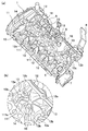
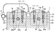
- FIG. 1 It is a perspective view of the head cover structure of the internal combustion engine which concerns on this embodiment. It is a perspective view which shows the state which looked up at the head cover from the bottom, (a) is a general view, (b) is an enlarged view of the A section shown in (a). It is the II sectional view taken on the line shown in FIG. It is the II-II sectional view taken on the line shown in FIG.
- Embodiments of the present invention will be described in detail with reference to FIGS.
- a case where the present invention is applied to a head cover of an automobile engine will be described as an example.
- the same elements are assigned the same numbers, and duplicate descriptions are omitted.
- the direction will be described based on front (F) rear (B) left (L) right (R) shown in FIG.
- the internal combustion engine E is an in-line four-cylinder DOHC (Double Overhead Camshaft) type engine.
- DOHC Double Overhead Camshaft
- a basic structure such as a cylinder block for storing oil and an oil pan for storing oil is provided.
- the internal combustion engine E is placed horizontally so that the cylinder row direction is the left-right direction with respect to the vehicle, and is configured to intake from the rear and exhaust from the front.
- the cylinder head 2 is a member constituting a combustion chamber, an intake port, and an exhaust port (not shown).
- the cylinder head 2 has an intake valve and an exhaust valve (not shown) that open and close the intake port and the exhaust port, respectively, and a valve operating mechanism that drives the intake valve and the exhaust valve above the cylinder head 2. 3 is installed. Further, a transmission mechanism 4 for transmitting the rotation of the crank to the valve operating mechanism 3 is provided at the side of the cylinder head 2 (more specifically, the internal combustion engine E).
- the cylinder head 2 has an outer peripheral wall 21 that rises in a frame shape along the outer peripheral edge of the upper surface 2a, and a central wall 22 that rises from the center in the front-rear direction of the upper surface 2a.
- the cylinder head 2 includes a plurality of lower bearing portions 23 for supporting cam shafts 31 and 32 of the valve operating mechanism 3 between the outer peripheral wall 21 and the central wall 22.
- the lower bearing portion 23 is a wall-like portion extending in the front-rear direction, and has a semicircular recess 23 a at the center of the upper surface thereof.
- the lower bearing portion 23 is provided at a position corresponding to the upper bearing portion 13 provided in the head cover 1 described later.
- the valve operating mechanism 3 includes a pair of cam shafts 31 and 32 arranged in parallel to each other along the cylinder row direction, and a plurality of cams 33 (see FIG. 4) fixed to the cam shaft 31 and the cam shaft 32, respectively. ,have.
- the cam shaft 31 is an intake side cam shaft for opening and closing the intake valve
- the cam shaft 32 is an exhaust side cam shaft for opening and closing the exhaust valve.
- the head cover 1 is an aluminum alloy member that is attached to the upper part of the cylinder head 2 and covers the valve mechanism 3.
- the head cover 1 includes a covering portion 11 that covers the valve operating mechanism 3, an outer peripheral edge portion 12 that forms the outer peripheral edge of the head cover 1, an upper bearing portion 13 that supports the cam shafts 31 and 32 of the valve operating mechanism 3, It has mainly.
- a concave groove portion 14 for installing a fuel injection device extends in the left-right direction at the center portion of the head cover 1 in the front-rear direction.
- the outer peripheral edge portion 12 is a frame-shaped portion provided on the outer peripheral edge of the covering portion 11.
- the outer peripheral edge 12 is installed on an outer peripheral wall 21 provided on the upper surface of the cylinder head 2.
- the outer peripheral edge portion 12 has a plurality of bolt insertion holes 12a for inserting bolts B as fastening members, and some of them are provided between the adjacent upper bearing portions 13.
- the bolt insertion hole 12a corresponds to an “outer periphery side fastening portion” in the claims.
- a bolt fastening hole 21a for fastening the bolt B is formed in the outer peripheral wall 21 of the cylinder head 2 at a position corresponding to the bolt insertion hole 12a (see FIG. 4).
- the upper bearing portion 13 is a portion that rotatably holds the cam shafts 31 and 32 of the valve operating mechanism 3 in cooperation with a plurality of lower bearing portions 23 provided in the cylinder head 2.
- the upper bearing portion 13 is a wall-like portion extending in the front-rear direction, and is provided apart from each other in the left-right direction between the outer peripheral edge portion 12 and the recessed groove portion 14.
- the upper bearing portion 13 is disposed on both the left and right sides of each cylinder.
- the upper bearing portion 13c disposed on the left side of the leftmost cylinder also serves as the left end portion 12b (see FIG. 2A) of the outer peripheral edge portion 12.
- a semicircular recess 13 a is provided at the center of the lower surface of the upper bearing portion 13 in the front-rear direction.
- the concave portion 13a provided in the upper bearing portion 13 and the concave portion 23a provided in the lower bearing portion 23 constitute a bearing portion that rotatably supports the cam shafts 31 and 32, respectively.
- Bolt insertion holes 13b for inserting bolts B as fastening members are provided on both front and rear sides of the recess 13a.
- the bolt insertion hole 13b corresponds to a “bearing side fastening and fixing portion” in the claims.
- a bolt fastening hole 23b for fastening the bolt B is formed in the lower bearing portion 23 of the cylinder head 2 at a position corresponding to the bolt insertion hole 13b.
- coated part 11 is a thin-plate-shaped site
- the covering portion 11 has a bulging portion 111 that bulges substantially hemispherically toward the upper side between the adjacent upper bearing portions 13. Further, as shown in FIG. 1, the covering portion 11 has a first reinforcing rib 15 for reinforcing the bulging portion 111.
- the first reinforcing rib 15 extends so as to rise between the bolt insertion hole 12a of the outer peripheral edge portion 12 provided between the adjacent upper bearing portions 13 and the bolt insertion hole 13b of the upper bearing portion 13. Yes.
- substantially hemispherical includes a hemispherical shape and a shape that can be regarded as equivalent to a hemispherical shape (so-called dome shape or the like).
- the lower surface of the bulging portion 111 is provided between the bolt insertion hole 13 b of the upper bearing portion 13 and the adjacent upper bearing portions 13 from the apex 111 a of the bulging portion 111.
- the second reinforcing ribs 16 extend radially toward the bolt insertion holes 12a of the outer peripheral edge portion 12 and the concave groove portion 14.
- the second reinforcing ribs 16 are arranged substantially symmetrically with the vertex 111a as the center. Thereby, since the bulging part 111 is reinforced uniformly, a vibration and a noise can be reduced. Further, the second reinforcing rib 16 is curved so as to be convex upward along the lower surface of the bulging portion 111 in order to avoid interference with the cam 33 (see FIG. 4).
- a common rail 5 for supplying high-pressure fuel to a fuel injection device (not shown) is attached to the rear end portion of the head cover 1.
- a cam angle sensor 6 that detects the rotation angle of the cam shaft 32 is attached to the upper surface of the head cover 1.
- a negative pressure pump 7 that supplies hydraulic pressure to a variable valve timing mechanism (not shown) of the valve operating mechanism 3 is attached to the left end of the head cover 1.
- An engine hanger 8 for holding the internal combustion engine E on a body frame (not shown) is attached to the left side of the front end portion of the head cover 1.
- an opening 9 for discharging blow-by gas to a gas-liquid separation chamber (not shown) provided separately from the head cover 1 is provided on the upper surface of the right end portion of the head cover 1.
- the head cover structure of the internal combustion engine according to the present embodiment is basically configured as described above. Next, the function and effect will be described.
- the upper bearing portion 13 that pivotally supports the cam shafts 31 and 32 is provided integrally with the head cover 1, and is substantially between adjacent upper bearing portions 13. Since the bulging portion 111 bulging in a hemispherical shape is formed, the rigidity of the covering portion 11 is enhanced by the substantially hemispherical bulging portion 111. Therefore, the rigidity of the head cover 1 can be improved as a whole while suppressing the increase in thickness and size of the head cover 1, and vibration and noise can be suppressed.
- the first reinforcing rib 15 is provided between the bolt insertion hole 12 a of the outer peripheral edge portion 12 provided between the adjacent upper bearing portions 13 and the bolt insertion hole 13 b of the upper bearing portion 13.
- the bulging portion 111 is provided at a portion surrounded by the adjacent upper bearing portion 13 and the first reinforcing rib 15, the rigidity of the head cover 1 can be further enhanced, and vibration and noise can be suppressed. become.
- the bolt of the outer peripheral edge portion 12 provided between the bolt insertion hole 13 b of the upper bearing portion 13 and the adjacent upper bearing portions 13 from the apex 111 a of the bulging portion 111. Since the second reinforcing ribs 16 extend radially toward the insertion hole 12a and the recessed groove portion 14, the rigidity of the bulging portion 111 can be further increased, and vibration and noise can be further suppressed. Can do.
- the bulging portion 111 can be uniformly reinforced, and vibration and noise can be reduced.
- the rigidity of the head cover 1 is enhanced as a whole by the bulging portion 111, auxiliary devices such as the common rail 5, the cam angle sensor 6, the negative pressure pump 7, and the engine hanger 8 can be attached to the head cover 1. it can. Therefore, the degree of freedom in the layout of the internal combustion engine E can be improved.
- the present invention is applied to a so-called DOHC type internal combustion engine E.
- DOHC Double Overhead Camshaft
- the present invention is not limited to this, and may be applied to an SOHC (Single Overhead Camshaft) type internal combustion engine, for example.
- the gas-liquid separation chamber is provided separately from the head cover 1, but the gas-liquid separation chamber may be provided inside the head cover 1.
- the head cover 1 can be reduced in weight and size by providing, for example, a resin-made gas-liquid separation chamber that communicates with the opening 9 separately from the head cover 1.
- the bulging part 111 was formed between all the adjacent upper bearing parts 13, this invention is not limited to this, A plurality of adjacent upper bearing parts 13 The bulging part 111 should just be formed in the location where reinforcement is required among them.
Abstract
The goal of the present invention is to provide an internal combustion engine head-cover structure capable of suppressing an increase in the wall thickness and size of a head cover and enhancing the rigidity of the head cover. An internal combustion engine (E) head-cover structure is provided with the following: a covering part (11) which is disposed on a cylinder head (2) and which covers, from above, a valve gear (3) that includes cam shafts (31, 32); an outer peripheral edge part (12) which is provided along the outer peripheral edge of the covering part (11) and is fastened to the cylinder head (2); and a plurality of upper bearing parts (13) which are provided integrally with the covering part (11) and the outer peripheral edge part (12) and rotatably hold the cam shafts (31, 32) in cooperation with a plurality of lower bearing parts (23) provided on the cylinder head (2). The internal combustion engine (E) head-cover structure is characterized by the following: the upper bearing parts (13) are fastened and fixed to the lower bearing parts (23); and the covering part (11) has an expansion part (111) expanding in a substantially hemispherical shape between adjacent upper bearing parts (13).
Description
本発明は、内燃機関のヘッドカバー構造に関する。
The present invention relates to a head cover structure for an internal combustion engine.
従来、内燃機関のシリンダヘッドの上部には、燃焼室に連通する吸気ポート及び排気ポートをそれぞれ開閉するための吸気バルブ及び排気バルブを駆動する動弁機構が設けられている。また、シリンダヘッドの上部には、動弁機構を被覆するヘッドカバーが取り付けられている。
Conventionally, a valve operating mechanism for driving an intake valve and an exhaust valve for opening and closing an intake port and an exhaust port respectively communicating with a combustion chamber is provided on an upper portion of a cylinder head of an internal combustion engine. A head cover that covers the valve mechanism is attached to the upper part of the cylinder head.
例えば、特許文献1に記載のヘッドカバー構造では、カム軸を上下に挟んで軸支する複数の軸受部材のうちカム軸の上側に配置される上側部材が、ヘッドカバーと一体に形成されている。上側部材は、カム軸の軸方向に等間隔で配置されており、隣り合う上側部材同士の間を被覆する被覆部は、略平坦な板状に形成されている。
For example, in the head cover structure described in Patent Document 1, an upper member arranged on the upper side of the cam shaft among a plurality of bearing members that are pivotally supported with the cam shaft interposed therebetween is formed integrally with the head cover. The upper members are arranged at equal intervals in the axial direction of the cam shaft, and the covering portion that covers between the adjacent upper members is formed in a substantially flat plate shape.
ところで、近年、内燃機関のレイアウト性を考慮して、カム軸の回転角度を検出するカム角度センサ(TDCセンサ)や燃料噴射装置に高圧燃料を供給するコモンレールなどの補器を、ヘッドカバーに取り付けることが考えられている。
しかしながら、従来のヘッドカバー構造では、ヘッドカバーの振動によってカム角度センサの検出精度が低下してしまうおそれがある。また、従来シリンダヘッドに取り付けられていたコモンレールなどの補器を、シリンダヘッドよりも比較的剛性の低いヘッドカバーに取り付けた場合、振動や騒音が増大するおそれがあった。そのため、ヘッドカバーの更なる剛性の強化が望まれていた。
一方で、内燃機関の軽量化、コンパクト化の要請もあるため、ヘッドカバーの厚肉化や大型化による剛性向上には限界がある。 By the way, in recent years, considering the layout of the internal combustion engine, auxiliary devices such as a cam angle sensor (TDC sensor) for detecting the rotation angle of the cam shaft and a common rail for supplying high-pressure fuel to the fuel injection device are attached to the head cover. Is considered.
However, in the conventional head cover structure, there is a possibility that the detection accuracy of the cam angle sensor may be lowered due to vibration of the head cover. Further, when an auxiliary device such as a common rail that has been conventionally attached to the cylinder head is attached to a head cover that is relatively less rigid than the cylinder head, vibration and noise may increase. Therefore, further enhancement of the rigidity of the head cover has been desired.
On the other hand, since there is a demand for a lighter and more compact internal combustion engine, there is a limit to improving rigidity by increasing the thickness and size of the head cover.
本発明は、これらの問題に鑑みて成されたものであり、ヘッドカバーの厚肉化や大型化を抑制しつつ、ヘッドカバーの剛性を向上させることができる内燃機関のヘッドカバー構造を提供することを課題とする。
The present invention has been made in view of these problems, and it is an object of the present invention to provide a head cover structure for an internal combustion engine that can improve the rigidity of the head cover while suppressing the increase in thickness and size of the head cover. And
本発明に係る内燃機関のヘッドカバー構造は、シリンダヘッドに配置されたカム軸を含む動弁機構を上側から被覆する被覆部と、前記被覆部の外周縁に沿って設けられ、前記シリンダヘッドに締結される外周縁部と、前記被覆部及び前記外周縁部と一体に設けられ、前記シリンダヘッドに設けられた複数の下側軸受部と協働して前記カム軸を回転自在に保持する複数の上側軸受部と、を備える内燃機関のヘッドカバー構造であって、前記上側軸受部は、前記下側軸受部に締結固定され、前記被覆部は、隣り合う前記上側軸受部同士の間に、略半球状に膨出する膨出部を有することを特徴とする。
A head cover structure for an internal combustion engine according to the present invention is provided along the outer periphery of the covering portion that covers a valve operating mechanism including a cam shaft disposed on the cylinder head from above, and is fastened to the cylinder head. A plurality of outer peripheral edge portions integrally provided with the covering portion and the outer peripheral edge portion, and rotatably supporting the camshaft in cooperation with a plurality of lower bearing portions provided on the cylinder head. An upper bearing portion, wherein the upper bearing portion is fastened and fixed to the lower bearing portion, and the covering portion is substantially hemispherical between the adjacent upper bearing portions. It has the bulging part which bulges in a shape.
かかる構成によれば、隣り合う上側軸受部同士の間に、略半球状に膨出する膨出部を有しているので、略半球状の膨出部によって被覆部の剛性が高められる。そして、この膨出部によってヘッドカバーの剛性が高められ、振動や騒音を抑制することが可能になる。また、膨出部の形状によってヘッドカバーの剛性が高められるので、ヘッドカバーの厚肉化や大型化を抑制することができる。
According to such a configuration, since the bulging portion that bulges in a substantially hemispherical shape is provided between the adjacent upper bearing portions, the rigidity of the covering portion is enhanced by the substantially hemispherical bulging portion. And the rigidity of a head cover is improved by this bulging part, and it becomes possible to suppress a vibration and a noise. In addition, since the rigidity of the head cover is enhanced by the shape of the bulging portion, it is possible to suppress an increase in thickness and size of the head cover.
また、前記上側軸受部は、前記下側軸受部に締結固定される軸受側締結固定部を有し、前記外周縁部は、隣り合う前記上側軸受部の中間となる部位に、前記シリンダヘッドに締結固定される外周側締結固定部を有し、前記軸受側締結固定部と前記外周側締結固定部の間には第1補強リブが設けられ、隣り合う前記上側軸受部と前記第1補強リブとで囲まれた部位に前記膨出部が設けられている構成とするのが好ましい。
The upper bearing portion has a bearing-side fastening and fixing portion that is fastened and fixed to the lower bearing portion, and the outer peripheral edge portion is provided in the middle of the adjacent upper bearing portion in the cylinder head. An outer peripheral side fastening and fixing portion to be fastened and fixed, a first reinforcing rib is provided between the bearing side fastening and fixing portion and the outer peripheral side fastening and fixing portion, and the adjacent upper bearing portion and the first reinforcing rib It is preferable that the bulging portion is provided in a portion surrounded by.
かかる構成によれば、軸受側締結固定部と外周側締結固定部との間に第1補強リブが設けられ、隣り合う上側軸受部と第1補強リブとで囲まれた部位に膨出部が設けられているので、ヘッドカバーの剛性が一層高められ、振動や騒音をさらに抑制することが可能になる。
According to such a configuration, the first reinforcing rib is provided between the bearing side fastening and fixing portion and the outer periphery side fastening and fixing portion, and the bulging portion is located at a portion surrounded by the adjacent upper bearing portion and the first reinforcing rib. Since it is provided, the rigidity of the head cover can be further increased, and vibration and noise can be further suppressed.
また、前記膨出部の下面には、前記膨出部の頂点から前記軸受側締結固定部及び前記外周側締結固定部に向かって第2補強リブが延設されている構成とするのが好ましい。
Moreover, it is preferable that the lower surface of the bulging part has a configuration in which second reinforcing ribs are extended from the apex of the bulging part toward the bearing side fastening and fixing part and the outer peripheral side fastening and fixing part. .
かかる構成によれば、膨出部の剛性を一層高めることができるので、ヘッドカバーの剛性がさらに一層高められ、振動や騒音をさらに抑制することが可能になる。
According to such a configuration, since the rigidity of the bulging portion can be further increased, the rigidity of the head cover can be further increased, and vibration and noise can be further suppressed.
また、前記カム軸は、吸気側カム軸と排気側カム軸とからなり、前記上側軸受部は、前記吸気側カム軸と前記排気側カム軸のそれぞれに沿って複数配置され、前記吸気側カム軸の前記上側軸受部間、及び、前記排気側カム軸の前記上側軸受部間の少なくとも一方に、前記膨出部が設けられている構成とするのが好ましい。
The cam shaft includes an intake side cam shaft and an exhaust side cam shaft, and a plurality of the upper bearing portions are arranged along each of the intake side cam shaft and the exhaust side cam shaft, and the intake side cam shaft It is preferable that the bulging portion is provided between at least one of the upper bearing portions of the shaft and between the upper bearing portions of the exhaust cam shaft.
かかる構成によれば、いわゆるDOHC(Double OverHead Camshaft)タイプの内燃機関において、ヘッドカバーの剛性を高めることができ、振動や騒音を抑制することが可能になる。
According to such a configuration, in a so-called DOHC (Double Overhead Camshaft) type internal combustion engine, the rigidity of the head cover can be increased, and vibration and noise can be suppressed.
本発明によれば、ヘッドカバーの剛性を向上させることができる内燃機関のヘッドカバー構造を提供することができる。
According to the present invention, it is possible to provide a head cover structure for an internal combustion engine that can improve the rigidity of the head cover.
本発明の実施形態について、図1乃至図4を参照して詳細に説明する。本実施形態では、自動車のエンジンのヘッドカバーに本発明を適用した場合を例にとって説明する。説明において、同一の要素には同一の番号を付し、重複する説明は省略する。また、方向を説明する場合は、図1に示す前(F)後(B)左(L)右(R)に基づいて説明する。
Embodiments of the present invention will be described in detail with reference to FIGS. In the present embodiment, a case where the present invention is applied to a head cover of an automobile engine will be described as an example. In the description, the same elements are assigned the same numbers, and duplicate descriptions are omitted. Further, the direction will be described based on front (F) rear (B) left (L) right (R) shown in FIG.
図1に示すように、内燃機関Eは、直列4気筒のDOHC(Double OverHead Camshaft)タイプのエンジンであり、ヘッドカバー1及びシリンダヘッド2の他に、図示は省略するが、ピストン、コンロッド、クランクなどを収容するシリンダブロックや、オイルを貯留するオイルパン、などの基本構成を備えている。内燃機関Eは、車両に対して気筒列方向が左右方向となるように横置きされており、後方から吸気して前方から排気するように構成されている。
As shown in FIG. 1, the internal combustion engine E is an in-line four-cylinder DOHC (Double Overhead Camshaft) type engine. A basic structure such as a cylinder block for storing oil and an oil pan for storing oil is provided. The internal combustion engine E is placed horizontally so that the cylinder row direction is the left-right direction with respect to the vehicle, and is configured to intake from the rear and exhaust from the front.
シリンダヘッド2は、燃焼室や吸気ポートや排気ポート(図示省略)を構成する部材である。シリンダヘッド2は、吸気ポート及び排気ポートを夫々開閉する吸気バルブ及び排気バルブ(図示省略)を有しており、シリンダヘッド2の上部には、これらの吸気バルブ及び排気バルブを駆動する動弁機構3が設置されている。また、シリンダヘッド2(より詳しくは内燃機関E)の側部には、クランクの回転を動弁機構3に伝達する伝達機構4が設けられている。
The cylinder head 2 is a member constituting a combustion chamber, an intake port, and an exhaust port (not shown). The cylinder head 2 has an intake valve and an exhaust valve (not shown) that open and close the intake port and the exhaust port, respectively, and a valve operating mechanism that drives the intake valve and the exhaust valve above the cylinder head 2. 3 is installed. Further, a transmission mechanism 4 for transmitting the rotation of the crank to the valve operating mechanism 3 is provided at the side of the cylinder head 2 (more specifically, the internal combustion engine E).
図4に示すように、シリンダヘッド2は、上面2aの外周縁に沿って枠状に立ち上がる外周壁21と、上面2aの前後方向の中央部から立ち上がる中央壁22と、を有している。また、図3に示すように、シリンダヘッド2は、外周壁21と中央壁22との間に、動弁機構3のカム軸31,32を軸支するための複数の下側軸受部23を有している。下側軸受部23は、前後方向に延設された壁状の部位であり、その上面の中央部に半円状の凹部23aを有している。下側軸受部23は、後記するヘッドカバー1に設けられた上側軸受部13に対応する位置に設けられている。
As shown in FIG. 4, the cylinder head 2 has an outer peripheral wall 21 that rises in a frame shape along the outer peripheral edge of the upper surface 2a, and a central wall 22 that rises from the center in the front-rear direction of the upper surface 2a. As shown in FIG. 3, the cylinder head 2 includes a plurality of lower bearing portions 23 for supporting cam shafts 31 and 32 of the valve operating mechanism 3 between the outer peripheral wall 21 and the central wall 22. Have. The lower bearing portion 23 is a wall-like portion extending in the front-rear direction, and has a semicircular recess 23 a at the center of the upper surface thereof. The lower bearing portion 23 is provided at a position corresponding to the upper bearing portion 13 provided in the head cover 1 described later.
動弁機構3は、気筒列方向に沿って互いに平行に配置された一対のカム軸31,32と、このカム軸31,カム軸32にそれぞれ固定された複数のカム33(図4参照)と、を有している。なお、カム軸31は、吸気バルブを開閉するための吸気側カム軸であり、カム軸32は、排気バルブを開閉するための排気側カム軸である。
The valve operating mechanism 3 includes a pair of cam shafts 31 and 32 arranged in parallel to each other along the cylinder row direction, and a plurality of cams 33 (see FIG. 4) fixed to the cam shaft 31 and the cam shaft 32, respectively. ,have. The cam shaft 31 is an intake side cam shaft for opening and closing the intake valve, and the cam shaft 32 is an exhaust side cam shaft for opening and closing the exhaust valve.
図1乃至図4に示すように、ヘッドカバー1は、シリンダヘッド2の上部に取り付けられて、動弁機構3を被覆するアルミ合金製の部材である。
ヘッドカバー1は、動弁機構3を被覆する被覆部11と、ヘッドカバー1の外周縁を構成する外周縁部12と、動弁機構3のカム軸31,32を軸支する上側軸受部13と、を主に有している。また、ヘッドカバー1の前後方向の中央部には、燃料噴射装置(図示省略)を設置するための凹溝部14が、左右方向に延設されている。 As shown in FIGS. 1 to 4, thehead cover 1 is an aluminum alloy member that is attached to the upper part of the cylinder head 2 and covers the valve mechanism 3.
Thehead cover 1 includes a covering portion 11 that covers the valve operating mechanism 3, an outer peripheral edge portion 12 that forms the outer peripheral edge of the head cover 1, an upper bearing portion 13 that supports the cam shafts 31 and 32 of the valve operating mechanism 3, It has mainly. Further, a concave groove portion 14 for installing a fuel injection device (not shown) extends in the left-right direction at the center portion of the head cover 1 in the front-rear direction.
ヘッドカバー1は、動弁機構3を被覆する被覆部11と、ヘッドカバー1の外周縁を構成する外周縁部12と、動弁機構3のカム軸31,32を軸支する上側軸受部13と、を主に有している。また、ヘッドカバー1の前後方向の中央部には、燃料噴射装置(図示省略)を設置するための凹溝部14が、左右方向に延設されている。 As shown in FIGS. 1 to 4, the
The
外周縁部12は、被覆部11の外周縁に設けられた枠状の部位である。外周縁部12は、シリンダヘッド2の上面に設けられた外周壁21の上に設置されている。外周縁部12は、締結部材であるボルトBを挿通するための複数のボルト挿通孔12aを有しており、そのうちの一部は、隣り合う上側軸受部13同士の間に設けられている。このボルト挿通孔12aが、特許請求の範囲における「外周側締結固定部」に相当する。なお、シリンダヘッド2の外周壁21には、ボルト挿通孔12aに対応する位置に、ボルトBを締結するためのボルト締結穴21aが形成されている(図4参照)。
The outer peripheral edge portion 12 is a frame-shaped portion provided on the outer peripheral edge of the covering portion 11. The outer peripheral edge 12 is installed on an outer peripheral wall 21 provided on the upper surface of the cylinder head 2. The outer peripheral edge portion 12 has a plurality of bolt insertion holes 12a for inserting bolts B as fastening members, and some of them are provided between the adjacent upper bearing portions 13. The bolt insertion hole 12a corresponds to an “outer periphery side fastening portion” in the claims. A bolt fastening hole 21a for fastening the bolt B is formed in the outer peripheral wall 21 of the cylinder head 2 at a position corresponding to the bolt insertion hole 12a (see FIG. 4).
上側軸受部13は、シリンダヘッド2に設けられた複数の下側軸受部23と協働して、動弁機構3のカム軸31,32をそれぞれ回転自在に保持する部位である。上側軸受部13は、前後方向に延設された壁状の部位であり、外周縁部12と凹溝部14の間において、左右方向に互いに離間して設けられている。上側軸受部13は、各気筒の左右両側に配置されている。なお、本実施形態では、最も左側の気筒の左側に配置された上側軸受部13cは、外周縁部12の左端部12b(図2(a)参照)を兼ねている。
The upper bearing portion 13 is a portion that rotatably holds the cam shafts 31 and 32 of the valve operating mechanism 3 in cooperation with a plurality of lower bearing portions 23 provided in the cylinder head 2. The upper bearing portion 13 is a wall-like portion extending in the front-rear direction, and is provided apart from each other in the left-right direction between the outer peripheral edge portion 12 and the recessed groove portion 14. The upper bearing portion 13 is disposed on both the left and right sides of each cylinder. In the present embodiment, the upper bearing portion 13c disposed on the left side of the leftmost cylinder also serves as the left end portion 12b (see FIG. 2A) of the outer peripheral edge portion 12.
図2、図3に示すように、上側軸受部13の下面の前後方向の中央部には、半円状の凹部13aが設けられている。この上側軸受部13に設けられた凹部13aと下側軸受部23に設けられた凹部23aとが、カム軸31,32をそれぞれ回転自在に軸支する軸受部を構成している。凹部13aの前後両側には、締結部材であるボルトBを挿通するためのボルト挿通孔13bが設けられている。このボルト挿通孔13bが、特許請求の範囲における「軸受側締結固定部」に相当する。なお、シリンダヘッド2の下側軸受部23には、ボルト挿通孔13bに対応する位置に、ボルトBを締結するためのボルト締結穴23bが形成されている。
As shown in FIGS. 2 and 3, a semicircular recess 13 a is provided at the center of the lower surface of the upper bearing portion 13 in the front-rear direction. The concave portion 13a provided in the upper bearing portion 13 and the concave portion 23a provided in the lower bearing portion 23 constitute a bearing portion that rotatably supports the cam shafts 31 and 32, respectively. Bolt insertion holes 13b for inserting bolts B as fastening members are provided on both front and rear sides of the recess 13a. The bolt insertion hole 13b corresponds to a “bearing side fastening and fixing portion” in the claims. A bolt fastening hole 23b for fastening the bolt B is formed in the lower bearing portion 23 of the cylinder head 2 at a position corresponding to the bolt insertion hole 13b.
被覆部11は、動弁機構3を被覆する薄板状の部位であり、動弁機構3に対して上方に離間して配置されている(図4参照)。被覆部11は、隣り合う上側軸受部13同士の間に、上側に向かって略半球状に膨出する膨出部111を有している。また、図1に示すように、被覆部11は、膨出部111を補強するための第1補強リブ15を有している。第1補強リブ15は、隣り合う上側軸受部13同士の間に設けられた外周縁部12のボルト挿通孔12aと上側軸受部13のボルト挿通孔13bとの間に立ち上がるように延設されている。これにより、膨出部111は、隣り合う上側軸受部13と第1補強リブとに囲まれて、周囲を補強された状態となる。
なお、膨出部111について、「略半球状」とは、半球状の他、半球状に等しいとみなすことができる形状(いわゆるドーム状など)を含むものとする。 The coating |coated part 11 is a thin-plate-shaped site | part which coat | covers the valve mechanism 3, and is spaced apart and arrange | positioned upwards with respect to the valve mechanism 3 (refer FIG. 4). The covering portion 11 has a bulging portion 111 that bulges substantially hemispherically toward the upper side between the adjacent upper bearing portions 13. Further, as shown in FIG. 1, the covering portion 11 has a first reinforcing rib 15 for reinforcing the bulging portion 111. The first reinforcing rib 15 extends so as to rise between the bolt insertion hole 12a of the outer peripheral edge portion 12 provided between the adjacent upper bearing portions 13 and the bolt insertion hole 13b of the upper bearing portion 13. Yes. Thereby, the bulging part 111 will be in the state where the circumference | surroundings were reinforced by being surrounded by the adjacent upper side bearing part 13 and the 1st reinforcement rib.
In addition, regarding the bulgingpart 111, “substantially hemispherical” includes a hemispherical shape and a shape that can be regarded as equivalent to a hemispherical shape (so-called dome shape or the like).
なお、膨出部111について、「略半球状」とは、半球状の他、半球状に等しいとみなすことができる形状(いわゆるドーム状など)を含むものとする。 The coating |
In addition, regarding the bulging
図2(b)に示すように、膨出部111の下面には、膨出部111の頂点111aから、上側軸受部13のボルト挿通孔13bと、隣り合う上側軸受部13同士の間に設けられた外周縁部12のボルト挿通孔12aと、凹溝部14と、に向かって、第2補強リブ16が放射状に延設されている。第2補強リブ16は、頂点111aを中心として略対称に配置されている。これにより、膨出部111が均一に補強されるので、振動や騒音を低減することができる。また、第2補強リブ16は、カム33との干渉を回避するために、膨出部111の下面に沿って上向きに凸となるように湾曲している(図4参照)。
As shown in FIG. 2B, the lower surface of the bulging portion 111 is provided between the bolt insertion hole 13 b of the upper bearing portion 13 and the adjacent upper bearing portions 13 from the apex 111 a of the bulging portion 111. The second reinforcing ribs 16 extend radially toward the bolt insertion holes 12a of the outer peripheral edge portion 12 and the concave groove portion 14. The second reinforcing ribs 16 are arranged substantially symmetrically with the vertex 111a as the center. Thereby, since the bulging part 111 is reinforced uniformly, a vibration and a noise can be reduced. Further, the second reinforcing rib 16 is curved so as to be convex upward along the lower surface of the bulging portion 111 in order to avoid interference with the cam 33 (see FIG. 4).
なお、図1に示すように、ヘッドカバー1の後端部には、図示しない燃料噴射装置に高圧燃料を供給するためのコモンレール5が取り付けられている。また、ヘッドカバー1の上面には、カム軸32の回転角度を検出するカム角度センサ6が取り付けられている。また、ヘッドカバー1の左側の端部には、動弁機構3のバルブタイミング可変機構(図示省略)に作動油圧を供給する負圧ポンプ7が取り付けられている。また、ヘッドカバー1の前端部の左側には、図示しない車体フレームに内燃機関Eを保持するためのエンジンハンガー8が取り付けられている。また、ヘッドカバー1の右端部の上面には、ヘッドカバー1と別体に設けた気液分離室(図示省略)へブローバイガスを排出するための開口部9が設けられている。
As shown in FIG. 1, a common rail 5 for supplying high-pressure fuel to a fuel injection device (not shown) is attached to the rear end portion of the head cover 1. A cam angle sensor 6 that detects the rotation angle of the cam shaft 32 is attached to the upper surface of the head cover 1. A negative pressure pump 7 that supplies hydraulic pressure to a variable valve timing mechanism (not shown) of the valve operating mechanism 3 is attached to the left end of the head cover 1. An engine hanger 8 for holding the internal combustion engine E on a body frame (not shown) is attached to the left side of the front end portion of the head cover 1. Further, an opening 9 for discharging blow-by gas to a gas-liquid separation chamber (not shown) provided separately from the head cover 1 is provided on the upper surface of the right end portion of the head cover 1.
本実施形態に係る内燃機関のヘッドカバー構造は、基本的に以上のように構成されるものであり、次に、その作用効果について説明する。
The head cover structure of the internal combustion engine according to the present embodiment is basically configured as described above. Next, the function and effect will be described.
本実施形態に係る内燃機関のヘッドカバー構造によれば、カム軸31,32を軸支する上側軸受部13がヘッドカバー1と一体に設けられており、隣り合う上側軸受部13同士の間に、略半球状に膨出する膨出部111が形成されているので、略半球状の膨出部111によって被覆部11の剛性が高められる。そのため、ヘッドカバー1の厚肉化や大型化を抑制しつつ、ヘッドカバー1の剛性が全体的に高められ、振動や騒音を抑制することが可能になる。
According to the head cover structure of the internal combustion engine according to the present embodiment, the upper bearing portion 13 that pivotally supports the cam shafts 31 and 32 is provided integrally with the head cover 1, and is substantially between adjacent upper bearing portions 13. Since the bulging portion 111 bulging in a hemispherical shape is formed, the rigidity of the covering portion 11 is enhanced by the substantially hemispherical bulging portion 111. Therefore, the rigidity of the head cover 1 can be improved as a whole while suppressing the increase in thickness and size of the head cover 1, and vibration and noise can be suppressed.
また、かかる構成によれば、隣り合う上側軸受部13の間に設けられた外周縁部12のボルト挿通孔12aと上側軸受部13のボルト挿通孔13bとの間に第1補強リブ15が設けられ、隣り合う上側軸受部13と第1補強リブ15とで囲まれた部位に膨出部111が設けられているので、ヘッドカバー1の剛性が一層高められ、振動や騒音を抑制することが可能になる。
Further, according to this configuration, the first reinforcing rib 15 is provided between the bolt insertion hole 12 a of the outer peripheral edge portion 12 provided between the adjacent upper bearing portions 13 and the bolt insertion hole 13 b of the upper bearing portion 13. In addition, since the bulging portion 111 is provided at a portion surrounded by the adjacent upper bearing portion 13 and the first reinforcing rib 15, the rigidity of the head cover 1 can be further enhanced, and vibration and noise can be suppressed. become.
また、膨出部111の下面には、膨出部111の頂点111aから、上側軸受部13のボルト挿通孔13bと、隣り合う上側軸受部13同士の間に設けられた外周縁部12のボルト挿通孔12aと、凹溝部14と、に向かって、第2補強リブ16が放射状に延設されているので、膨出部111の剛性を一層高めることができ、振動や騒音を一層抑制することができる。
Further, on the lower surface of the bulging portion 111, the bolt of the outer peripheral edge portion 12 provided between the bolt insertion hole 13 b of the upper bearing portion 13 and the adjacent upper bearing portions 13 from the apex 111 a of the bulging portion 111. Since the second reinforcing ribs 16 extend radially toward the insertion hole 12a and the recessed groove portion 14, the rigidity of the bulging portion 111 can be further increased, and vibration and noise can be further suppressed. Can do.
また、第2補強リブ16は、頂点111aを中心として略対称に配置されているので、膨出部111を均一に補強することができ、振動や騒音を低減することができる。
Further, since the second reinforcing ribs 16 are arranged substantially symmetrically with the vertex 111a as the center, the bulging portion 111 can be uniformly reinforced, and vibration and noise can be reduced.
また、ヘッドカバー1は、膨出部111によって全体的に剛性が高められているので、コモンレール5、カム角度センサ6、負圧ポンプ7、エンジンハンガー8、などの補器をヘッドカバー1に取り付けることができる。そのため、内燃機関Eのレイアウトの自由度を向上させることができる。
Further, since the rigidity of the head cover 1 is enhanced as a whole by the bulging portion 111, auxiliary devices such as the common rail 5, the cam angle sensor 6, the negative pressure pump 7, and the engine hanger 8 can be attached to the head cover 1. it can. Therefore, the degree of freedom in the layout of the internal combustion engine E can be improved.
以上、本発明の実施形態について図面を参照して詳細に説明したが、本発明はこれに限定されるものではなく、発明の主旨を逸脱しない範囲で適宜変更可能である。
As mentioned above, although embodiment of this invention was described in detail with reference to drawings, this invention is not limited to this, In the range which does not deviate from the main point of invention, it can change suitably.
例えば、本実施形態では、いわゆるDOHCタイプの内燃機関Eに本発明を適用したが、これに限定されるものではなく、例えばSOHC(Single OverHead Camshaft)タイプの内燃機関に適用してもよい。
For example, in the present embodiment, the present invention is applied to a so-called DOHC type internal combustion engine E. However, the present invention is not limited to this, and may be applied to an SOHC (Single Overhead Camshaft) type internal combustion engine, for example.
また、本実施形態では、ヘッドカバー1の外部に気液分離室を別体に設ける構成としたが、ヘッドカバー1の内部に気液分離室を設ける構成としてもよい。なお、本実施形態では、この開口部9に連通する例えば樹脂製の気液分離室をヘッドカバー1と別体に設けることで、ヘッドカバー1の軽量化、コンパクト化を図ることができる。
In this embodiment, the gas-liquid separation chamber is provided separately from the head cover 1, but the gas-liquid separation chamber may be provided inside the head cover 1. In the present embodiment, the head cover 1 can be reduced in weight and size by providing, for example, a resin-made gas-liquid separation chamber that communicates with the opening 9 separately from the head cover 1.
また、本実施形態では、すべての隣り合う上側軸受部13同士の間に膨出部111を形成したが、本発明はこれに限定されるものではなく、複数の隣り合う上側軸受部13同士の間のうち、補強が必要とされる箇所に膨出部111が形成されていればよい。
Moreover, in this embodiment, although the bulging part 111 was formed between all the adjacent upper bearing parts 13, this invention is not limited to this, A plurality of adjacent upper bearing parts 13 The bulging part 111 should just be formed in the location where reinforcement is required among them.
1 ヘッドカバー
11 被覆部
111 膨出部
12 外周縁部
13 上側軸受部
13b ボルト挿通孔
15 第1補強リブ
16 第2補強リブ
2 シリンダヘッド
23 下側軸受部
3 動弁機構 DESCRIPTION OFSYMBOLS 1 Head cover 11 Covering part 111 Swelling part 12 Outer peripheral edge part 13 Upper bearing part 13b Bolt insertion hole 15 1st reinforcement rib 16 2nd reinforcement rib 2 Cylinder head 23 Lower bearing part 3 Valve mechanism
11 被覆部
111 膨出部
12 外周縁部
13 上側軸受部
13b ボルト挿通孔
15 第1補強リブ
16 第2補強リブ
2 シリンダヘッド
23 下側軸受部
3 動弁機構 DESCRIPTION OF
Claims (4)
- シリンダヘッドに配置されたカム軸を含む動弁機構を上側から被覆する被覆部と、
前記被覆部の外周縁に沿って設けられ、前記シリンダヘッドに締結される外周縁部と、
前記被覆部及び前記外周縁部と一体に設けられ、前記シリンダヘッドに設けられた複数の下側軸受部と協働して前記カム軸を回転自在に保持する複数の上側軸受部と、
を備える内燃機関のヘッドカバー構造であって、
前記上側軸受部は、前記下側軸受部に締結固定され、
前記被覆部は、隣り合う前記上側軸受部同士の間に、略半球状に膨出する膨出部を有することを特徴とする内燃機関のヘッドカバー構造。 A covering portion that covers from above the valve operating mechanism including a camshaft disposed in the cylinder head;
An outer peripheral edge provided along the outer peripheral edge of the covering portion and fastened to the cylinder head;
A plurality of upper bearing portions that are provided integrally with the covering portion and the outer peripheral edge portion, and that rotatably support the camshaft in cooperation with a plurality of lower bearing portions provided in the cylinder head;
An internal combustion engine head cover structure comprising:
The upper bearing portion is fastened and fixed to the lower bearing portion,
The head cover structure for an internal combustion engine, wherein the covering portion has a bulging portion that bulges in a substantially hemispherical shape between the adjacent upper bearing portions. - 前記上側軸受部は、前記下側軸受部に締結固定される軸受側締結固定部を有し、
前記外周縁部は、隣り合う前記上側軸受部の中間となる部位に、前記シリンダヘッドに締結固定される外周側締結固定部を有し、
前記軸受側締結固定部と前記外周側締結固定部の間には第1補強リブが設けられ、
隣り合う前記上側軸受部と前記第1補強リブとで囲まれた部位に前記膨出部が設けられていることを特徴とする請求の範囲第1項に記載の内燃機関のヘッドカバー構造。 The upper bearing portion has a bearing side fastening and fixing portion fastened and fixed to the lower bearing portion,
The outer peripheral edge portion has an outer peripheral side fastening fixing portion that is fastened and fixed to the cylinder head at a portion that is intermediate between the adjacent upper bearing portions,
A first reinforcing rib is provided between the bearing side fastening and fixing portion and the outer periphery side fastening and fixing portion,
The head cover structure for an internal combustion engine according to claim 1, wherein the bulging portion is provided at a portion surrounded by the adjacent upper bearing portion and the first reinforcing rib. - 前記膨出部の下面には、前記膨出部の頂点から前記軸受側締結固定部及び前記外周側締結固定部に向かって第2補強リブが延設されていることを特徴とする請求の範囲第2項に記載の内燃機関のヘッドカバー構造。 The second reinforcing rib extends from the apex of the bulging portion toward the bearing side fastening and fixing portion and the outer peripheral side fastening and fixing portion on the lower surface of the bulging portion. 3. A head cover structure for an internal combustion engine according to item 2.
- 前記カム軸は、吸気側カム軸と排気側カム軸とからなり、
前記上側軸受部は、前記吸気側カム軸と前記排気側カム軸のそれぞれに沿って複数配置され、
前記吸気側カム軸の前記上側軸受部間、及び、前記排気側カム軸の前記上側軸受部間の少なくとも一方に、前記膨出部が設けられていることを特徴とする請求の範囲第1項から請求の範囲第3項のいずれか1項に記載の内燃機関のヘッドカバー構造。 The cam shaft is composed of an intake side cam shaft and an exhaust side cam shaft,
A plurality of the upper bearing portions are arranged along each of the intake side camshaft and the exhaust side camshaft,
The bulge portion is provided between at least one of the upper bearing portions of the intake-side cam shaft and between the upper bearing portions of the exhaust-side cam shaft. A head cover structure for an internal combustion engine according to any one of claims 3 to 5.
Priority Applications (3)
| Application Number | Priority Date | Filing Date | Title |
|---|---|---|---|
| JP2013501082A JP5581438B2 (en) | 2011-02-22 | 2012-02-22 | Internal combustion engine head cover structure |
| EP12749912.7A EP2679792B1 (en) | 2011-02-22 | 2012-02-22 | Internal combustion engine head-cover structure |
| CN201280010029.7A CN103403332B (en) | 2011-02-22 | 2012-02-22 | The head-cover structure of internal-combustion engine |
Applications Claiming Priority (2)
| Application Number | Priority Date | Filing Date | Title |
|---|---|---|---|
| JP2011-035549 | 2011-02-22 | ||
| JP2011035549 | 2011-02-22 |
Publications (1)
| Publication Number | Publication Date |
|---|---|
| WO2012115123A1 true WO2012115123A1 (en) | 2012-08-30 |
Family
ID=46720899
Family Applications (1)
| Application Number | Title | Priority Date | Filing Date |
|---|---|---|---|
| PCT/JP2012/054185 WO2012115123A1 (en) | 2011-02-22 | 2012-02-22 | Internal combustion engine head-cover structure |
Country Status (4)
| Country | Link |
|---|---|
| EP (1) | EP2679792B1 (en) |
| JP (1) | JP5581438B2 (en) |
| CN (1) | CN103403332B (en) |
| WO (1) | WO2012115123A1 (en) |
Cited By (2)
| Publication number | Priority date | Publication date | Assignee | Title |
|---|---|---|---|---|
| JP2015124730A (en) * | 2013-12-27 | 2015-07-06 | 株式会社マーレ フィルターシステムズ | Cover member |
| US20220275770A1 (en) * | 2021-02-26 | 2022-09-01 | Mahle International Gmbh | Cylinder head cover |
Families Citing this family (2)
| Publication number | Priority date | Publication date | Assignee | Title |
|---|---|---|---|---|
| FR3026789B1 (en) * | 2014-10-02 | 2016-11-04 | Renault Sa | INTERNAL COMBUSTION ENGINE HEAD COVER |
| JP6631176B2 (en) | 2015-11-09 | 2020-01-15 | いすゞ自動車株式会社 | Cylinder head structure of internal combustion engine and internal combustion engine |
Citations (4)
| Publication number | Priority date | Publication date | Assignee | Title |
|---|---|---|---|---|
| JPH0560014A (en) * | 1991-09-03 | 1993-03-09 | Yamaha Motor Co Ltd | Cylinder head cover structure of internal combustion engine |
| JP2007192104A (en) * | 2006-01-19 | 2007-08-02 | Toyota Motor Corp | Camshaft support structure for internal combustion engine |
| JP2008057406A (en) * | 2006-08-30 | 2008-03-13 | Toyota Motor Corp | Camshaft support structure for internal combustion engine |
| CN201206478Y (en) | 2008-04-22 | 2009-03-11 | 奇瑞汽车股份有限公司 | Cam spindle frame for engine |
Family Cites Families (6)
| Publication number | Priority date | Publication date | Assignee | Title |
|---|---|---|---|---|
| DE4323073A1 (en) * | 1993-07-10 | 1995-01-12 | Audi Ag | Reciprocating piston internal combustion engine |
| DE20120912U1 (en) * | 2001-12-24 | 2002-06-06 | Volkswagen Ag | Cylinder head cover for an internal combustion engine |
| FR2867520B1 (en) * | 2004-03-09 | 2006-05-05 | Renault Sas | INTERNAL COMBUSTION ENGINE WITH AN ENCLOSURE FOR CONTAINING FUEL LEAKS |
| US7654237B2 (en) * | 2007-01-23 | 2010-02-02 | Lanxess Corporation | Cam cover |
| DE202008013310U1 (en) * | 2008-10-07 | 2009-02-12 | Reinz-Dichtungs-Gmbh | Cylinder head cover with metallic coating of seats for oil control valves |
| US8065993B2 (en) * | 2008-12-16 | 2011-11-29 | Ford Global Technologies, Llc | Structural oil baffle for engine covers |
-
2012
- 2012-02-22 EP EP12749912.7A patent/EP2679792B1/en not_active Not-in-force
- 2012-02-22 WO PCT/JP2012/054185 patent/WO2012115123A1/en active Application Filing
- 2012-02-22 JP JP2013501082A patent/JP5581438B2/en not_active Expired - Fee Related
- 2012-02-22 CN CN201280010029.7A patent/CN103403332B/en active Active
Patent Citations (4)
| Publication number | Priority date | Publication date | Assignee | Title |
|---|---|---|---|---|
| JPH0560014A (en) * | 1991-09-03 | 1993-03-09 | Yamaha Motor Co Ltd | Cylinder head cover structure of internal combustion engine |
| JP2007192104A (en) * | 2006-01-19 | 2007-08-02 | Toyota Motor Corp | Camshaft support structure for internal combustion engine |
| JP2008057406A (en) * | 2006-08-30 | 2008-03-13 | Toyota Motor Corp | Camshaft support structure for internal combustion engine |
| CN201206478Y (en) | 2008-04-22 | 2009-03-11 | 奇瑞汽车股份有限公司 | Cam spindle frame for engine |
Non-Patent Citations (1)
| Title |
|---|
| See also references of EP2679792A4 * |
Cited By (2)
| Publication number | Priority date | Publication date | Assignee | Title |
|---|---|---|---|---|
| JP2015124730A (en) * | 2013-12-27 | 2015-07-06 | 株式会社マーレ フィルターシステムズ | Cover member |
| US20220275770A1 (en) * | 2021-02-26 | 2022-09-01 | Mahle International Gmbh | Cylinder head cover |
Also Published As
| Publication number | Publication date |
|---|---|
| CN103403332A (en) | 2013-11-20 |
| EP2679792A4 (en) | 2014-11-19 |
| JP5581438B2 (en) | 2014-08-27 |
| CN103403332B (en) | 2015-11-25 |
| EP2679792B1 (en) | 2016-01-20 |
| JPWO2012115123A1 (en) | 2014-07-07 |
| EP2679792A1 (en) | 2014-01-01 |
Similar Documents
| Publication | Publication Date | Title |
|---|---|---|
| EP1974128B1 (en) | Camshaft support structure for an internal combustion engine | |
| JP3966003B2 (en) | Internal combustion engine | |
| EP1748168B1 (en) | Mounting apparatus for cam angle sensor | |
| EP1974129B1 (en) | Camshaft support structure of an internal combustion engine | |
| JP5447852B2 (en) | Engine chain case structure | |
| US8857402B2 (en) | Engine with variable valve timing mechanism | |
| JP5581438B2 (en) | Internal combustion engine head cover structure | |
| US8161927B2 (en) | Valve system for overhead-camshaft-type internal combustion engine, and engine incorporating same | |
| US20100126459A1 (en) | Fixation structure for valve system rotation shaft of internal combustion engine | |
| US7581524B2 (en) | Engine front structure | |
| JP5695630B2 (en) | Timing train cover structure for internal combustion engine | |
| JP6237175B2 (en) | engine | |
| JP5779222B2 (en) | Oil control valve holding structure | |
| JP2014095329A5 (en) | ||
| JP2009293574A (en) | Upper structure of engine | |
| JP7132071B2 (en) | internal combustion engine front cover | |
| JP4210279B2 (en) | Bearing cap structure | |
| JP4552203B2 (en) | Engine superstructure | |
| JP7395945B2 (en) | Engine cover structure | |
| JP7322514B2 (en) | cylinder head | |
| JP6686417B2 (en) | engine | |
| JP5806583B2 (en) | Overhead cam engine | |
| JP6686416B2 (en) | engine |
Legal Events
| Date | Code | Title | Description |
|---|---|---|---|
| 121 | Ep: the epo has been informed by wipo that ep was designated in this application |
Ref document number: 12749912 Country of ref document: EP Kind code of ref document: A1 |
|
| ENP | Entry into the national phase |
Ref document number: 2013501082 Country of ref document: JP Kind code of ref document: A |
|
| NENP | Non-entry into the national phase |
Ref country code: DE |
|
| WWE | Wipo information: entry into national phase |
Ref document number: 2012749912 Country of ref document: EP |