EP2679792B1 - Internal combustion engine head-cover structure - Google Patents
Internal combustion engine head-cover structure Download PDFInfo
- Publication number
- EP2679792B1 EP2679792B1 EP12749912.7A EP12749912A EP2679792B1 EP 2679792 B1 EP2679792 B1 EP 2679792B1 EP 12749912 A EP12749912 A EP 12749912A EP 2679792 B1 EP2679792 B1 EP 2679792B1
- Authority
- EP
- European Patent Office
- Prior art keywords
- portions
- upper side
- outer peripheral
- side bearing
- cam shaft
- Prior art date
- Legal status (The legal status is an assumption and is not a legal conclusion. Google has not performed a legal analysis and makes no representation as to the accuracy of the status listed.)
- Not-in-force
Links
Images

Classifications
-
- F—MECHANICAL ENGINEERING; LIGHTING; HEATING; WEAPONS; BLASTING
- F02—COMBUSTION ENGINES; HOT-GAS OR COMBUSTION-PRODUCT ENGINE PLANTS
- F02F—CYLINDERS, PISTONS OR CASINGS, FOR COMBUSTION ENGINES; ARRANGEMENTS OF SEALINGS IN COMBUSTION ENGINES
- F02F7/00—Casings, e.g. crankcases or frames
- F02F7/006—Camshaft or pushrod housings
-
- F—MECHANICAL ENGINEERING; LIGHTING; HEATING; WEAPONS; BLASTING
- F01—MACHINES OR ENGINES IN GENERAL; ENGINE PLANTS IN GENERAL; STEAM ENGINES
- F01L—CYCLICALLY OPERATING VALVES FOR MACHINES OR ENGINES
- F01L1/00—Valve-gear or valve arrangements, e.g. lift-valve gear
- F01L1/02—Valve drive
- F01L1/04—Valve drive by means of cams, camshafts, cam discs, eccentrics or the like
- F01L1/047—Camshafts
- F01L2001/0476—Camshaft bearings
Definitions
- the present invention relates to a head cover structure for an internal combustion engine.
- the upper portion of the cylinder head for an internal combustion engine is provided with a valve train that drives intake valves and exhaust valves for opening and closing of intake ports and exhaust ports communicating with combustion chambers. Further, the upper portion of the cylinder head is provided with a head cover to cover the valve train.
- upper side members the upper side members being disposed on the upper side of a cam shaft, out of plural bearing members that axially support the cam shaft by sandwiching from the upper side and the lower side are integrally formed with the head cover.
- the upper side members are disposed at equal intervals along the axial direction of the cam shaft, wherein a cover portion for covering the gap between neighboring upside members is formed substantially in a flat plat shape.
- Patent Document 1 Chinese Examined Utility Model Registration Application No. CN201206478Y .
- Document DE4323073 A1 discloses a similar head cover structure.
- auxiliary units are a cam angle sensor (TDC sensor) for detecting the rotational angle of a cam shaft, a common rail for supplying high pressure fuel to a fuel injection device, and the like,.
- TDC sensor cam angle sensor
- a conventional head cover structure has a possibly of dropping the detection accuracy of a cam angle sensor by vibration of the head cover.
- the auxiliary units being for example a common rail having been conventionally attached to a cylinder head, it is possible to increase vibration and noise. Therefore, further increasing of the stiffness (in another word, rigidity) of a head cover has been desired.
- the present invention has been developed to solve these problems, and an object of the invention is to provide a head cover structure, for an internal combustion engine, that enables improvement in the stiffness of a head cover, while inhibiting an increase in thickness and size of the head cover.
- a head cover structure for an internal combustion engine, includes: a cover portion for covering, from an upper side, a valve train including a cam shaft/shafts disposed at a cylinder head; an outer peripheral marginal portion provided along an outer peripheral margin of the cover portion and tightened to the cylinder head; and a plurality of upper side bearing portions provided integrally with the cover portion and the outer peripheral marginal portion to rotatably hold the cam shaft/shafts in collaboration with a plurality of lower side bearing portions provided on the cylinder head, wherein the upper side bearing portions are tightened and fixed to the lower side bearing portions, and wherein the cover portion includes bulging portions bulging substantially in a hemispherical shape between neighboring ones of the upper side bearing portions.
- the stiffness of the cover portion is increased by the bulging portions substantially in a hemispherical shape. Further, as the stiffness of the head cover is increased by these bulging portions, it is possible to reduce vibration and sound. Further, as the stiffness of the head cover is increased by the shape of the bulging portions, it is possible to reduce an increase in the thickness and the size of the head cover.
- the upper side bearing portions include bearing side tightening/fixing portions tightened and fixed to the lower bearing portions;
- the outer peripheral marginal portion includes outer peripheral side tightening/fixing portions at middle parts between neighboring ones of the upper side bearing portions, the outer peripheral side tightening/fixing portions being tightened and fixed to the cylinder head;
- first reinforcement limbs are provided between the bearing side tightening/fixing portions and the outer peripheral side tightening/fixing portions; and the bulging portions are provided at parts surrounded by neighboring ones of the upper side bearing portions and the first reinforcement limbs.
- the stiffness of the head cover is further increased, and it is possible to further reduce vibration and noise.
- second reinforcement limbs are provided on lower surfaces of the bulging portions, extending from top points of the bulging portions toward the bearing side tightening/fixing portions and the outer peripheral side tightening/fixing portions.
- the cam shafts include an intake side cam shaft and an exhaust side cam shaft; the upper side bearing portions are disposed in a plural number respectively along the intake side cam shaft and the exhaust side cam shaft; and the bulging portions are provided at least between the upper side bearing portions along the intake side cam shaft or between the upper side bearing portions along the exhaust side cam shaft.
- a head cover structure for an internal combustion engine, that enables improvement in the stiffness of a head cover.
- FIGS. 1 to 4 An embodiment of the present invention will be described below in detail, referring to FIGS. 1 to 4 .
- the present embodiment will be described, taking an example of a case of applying the invention to a head cover for the engine of a vehicle.
- the same reference number will be assigned to the same elements, and overlapping description will be omitted.
- description of the directions will be based on front (F), back (B), left (L), and right (R) shown in FIG. 1 .
- an internal combustion engine E is an in-line four cylinder engine of DOHC (Double OverHead Camshaft) type.
- DOHC Double OverHead Camshaft
- the basic configuration of the internal combustion engine E includes, though not shown, a cylinder block for housing pistons, connecting rods, cranks, and the like, an oil pan for storing oil, and the like.
- the internal combustion engine E is transversely installed such that the direction of the row of cylinders is the left/right direction with respect to the vehicle, wherein air is taken in from the back and exhausted from the front.
- the cylinder head 2 is a member forming combustion chambers, intake ports and exhaust ports (not shown).
- the cylinder head 2 includes intake valves and exhaust valves (not shown) for opening and closing the intake ports and the exhaust ports respectively, and the upper portion of the cylinder head 2 is provided with a valve train 3 to drive these intake valves and exhaust valves. Further, the side portion of the cylinder head 2 (more concretely, for the internal combustion engine E) is provided with a transmission mechanism 4 for transmitting rotation of the cranks to the valve train 3.
- the cylinder head 2 includes an outer peripheral wall 21 standing up in a frame shape along the outer peripheral margin of an upper surface 2a, and a central wall 22 standing up from the central portion with respect to the front/back direction of the upper surface 2a. Further, as shown in FIG. 3 , between the outer peripheral wall 21 and the central wall 22, the cylinder head 2 is provided with plural lower side bearing portions 23 for axially supporting cam shafts 31, 32 of the valve train 3.
- the lower side bearing portions 23 are parts in a wall shape extending along the front/back direction, and have respective recessed portions 23a in a semicircular shape at the central portion of the upper surface thereof.
- the lower side bearing portions 23 are provided at positions corresponding to the positions of upper side bearing portion 13 provided on the later-described head cover 1.
- the valve train 3 includes the pair of cam shafts 31, 32 arranged along the direction of the row of cylinders and in parallel to each other, and plural cams 33 (see FIG. 4 ) that are fixed respectively to the cam shaft 31 and the cam shaft 32.
- the cam shaft 31 is an intake side cam shaft for opening and closing the intake valves
- the cam shaft 32 is an exhaust side cam shaft for opening and closing the exhaust valves.
- the head cover 1 is attached to the upper portion of the cylinder head 2, and is a metal member of an aluminum alloy for covering the valve train 3.
- the head cover 1 mainly includes a cover portion 11 for covering the valve train 3, an outer peripheral marginal portion 12 forming the outer peripheral margin of the head cover 1, and the upper side bearing portions 13 for axially supporting the cam shafts 31, 32 of the valve train 3. Further, at the central portion with respect to the front/back direction of the head cover 1, a recessed groove portion 14 is extended along the left/right direction for installing a fuel injection device (not shown).
- the outer peripheral marginal portion 12 is a part in a frame shape provided at the outer peripheral margin of the cover portion 11.
- the outer peripheral marginal portion 12 is arranged on the outer peripheral wall 21 provided on the upper surface of the cylinder head 2.
- the outer peripheral marginal portion 12 has plural bolt penetration holes 12a for penetration of bolts B, which are tightening members, and the bolt penetration holes 12a are partially provided between neighboring upper side bearing portions 13. These bolt penetration holes 12a correspond to 'outer peripheral side tightening/fixing portion' in claims.
- bolt tightening holes 21a for tightening the bolts B are formed at positions, the positions corresponding to the bolt penetration holes 12a, of the outer peripheral wall 21 (see FIG. 4 ).
- the upper side bearing portions 13 are parts for rotatably holding the cam shafts 31, 32 of the valve train 3 in collaboration with the plural lower side bearing portions 23 provided at the cylinder head 2.
- the upper side bearing portions 13 are wall shaped parts extending along the front/back direction and are provided between the outer peripheral marginal portion 12 and the recessed groove portion 14, being separated from each other along the left/right direction.
- the upper side bearing portions 13 are arranged on both the left and right sides of the respective cylinders.
- an upper side bearing portion 13c arranged on the left side of the leftmost cylinder serves also as the left end portion 12b (see FIG. 2A ) of the outer peripheral marginal portion 12.
- the central portion, with respect to the front/back direction, of the lower surfaces of the upper side bearing portions 13 are provided with respective recessed portions 13a in a semicircular shape.
- These recessed portions 13a provided on the upper side bearing portions 13 and the respective recessed portions 23a provided on the lower side bearing portions 23 form the bearing portions, which axially and rotatably support the respective cam shafts 31, 32.
- Bolt penetration holes 13b for penetration of bolts B, which are tightening members, are provided on the both the front and back sides of the recessed portions 13a. These bolt penetration holes 13b correspond to 'bearing side tightening/fixing portion' in claims.
- the lower side bearing portions 23 of the cylinder head 2 are provided with bolt tightening holes 23b for tightening bolts B at positions corresponding to the bolt penetration holes 13b.
- the cover portion 11 is a plate shaped part for covering the valve train 3, and is disposed being separated upward from the valve train 3 (see FIG. 4 ).
- the cover portion 11 has bulging portions 111 bulging upward in a substantially hemispherical shape between neighboring upper side bearing portions 13.
- the cover portion 11 has first reinforcement limbs 15 for reinforcing the bulging portions 111.
- the first reinforcement limbs 15 are extended such as to stand up between the bolt penetration holes 12a of the outer peripheral marginal portion 12 and bolt penetration holes 13b of the upper side bearing portions 13, the bolt penetration holes 12a being provided between neighboring upper side bearing portions 13.
- the bulging portions 111 are surrounded by neighboring upper side bearing portions 13 and the first reinforcement limbs, and are thus in a state of being peripherally reinforced.
- 'a substantially hemispherical shape' includes, in addition to a hemispherical shape, a shape that can be recognized to be equal to a hemispherical shape (so-called dome shape, etc.).
- second reinforcement limbs16 are radially provided, extending from the top point 111a of the bulging portion 111 toward the bolt penetration hole 13b of the upper side bearing portion 13, the bolt penetration hole 12a of the outer peripheral marginal portion 12, the bolt penetration hole 12a being provided between neighboring upper side bearing portions 13, and the recessed groove portion 14.
- the second reinforcement limbs 16 are disposed substantially symmetrically with the top point 111a as the center. As the bulging portion 111 is thereby uniformly reinforced, vibration and noise can be reduced. Further, in order to avoid interference with the cam 33, the second reinforcement limbs 16 are curved such as to be convex upward along the lower surface of the bulging portion 111 (see FIG. 4 ).
- a common rail 5 is attached to the back end portion of the head cover 1 to supply high pressure fuel to a fuel injection device, not shown.
- a cam angle sensor 6 is attached to the upper surface of the head cover 1 to detect the rotation angle of the cam shaft 32.
- a negative pressure pump 7 is attached to the end portion, on the left side, of the head cover 1 to supply an operational hydraulic pressure to a valve timing adjustable mechanism (not shown) of the valve train 3.
- an engine hanger 8 is attached on the left side of the front end portion of the head cover 1 to hold the internal combustion engine E at a vehicle body frame, not shown.
- an opening 9 is provided through the upper surface of the right end portion of the head cover 1 to exhaust blow-by gas to a gas-liquid separation chamber (not shown) provided separately from the head cover 1.
- the head cover structure, for an internal combustion engine, according to the present embodiment is basically configured as described above. The operation and advantage thereof will be described below.
- the upper side bearing portions 13 for axially supporting the cam shafts 31, 32 are provided integrally with the head cover 1, and bulging portions 111 bulging substantially in a hemispherical shape are formed between neighboring upper side bearing portions 13.
- the stiffness of the cover portion 11 is increased by the bulging portions 111 substantially in a hemispherical shape. Accordingly, it is possible to increase the stiffness of the head cover 1 as a whole and thereby reduce vibration and noise, while reducing an increase in the thickness and size of the head cover 1.
- first reinforcement limbs 15 are provided between a bolt penetration hole 12a of the outer peripheral marginal portion 12 and bolt penetration holes 13b of upper side bearing portions 13, the bolt penetration hole 12a being provided between the neighboring upper side bearing portions 13; and a bulging portion 111 is provided at a part surrounded by the neighboring upper side bearing portions 13 and the first reinforcement limbs 15. Accordingly, the stiffness of the head cover 1 is further increased, and it is thereby possible to reduce vibration and noise.
- second reinforcement limbs16 are radially provided, extending from the top point 111a of the bulging portion 111 toward the bolt penetration holes 13b of the upper side bearing portions 13, the bolt penetration hole 12a of the outer peripheral marginal portion 12, the bolt penetration hole 12a being provided between the neighboring upper side bearing portions 13, and the recessed groove portion 14. Accordingly, the stiffness of a bulging portion 111 can be further increased, and vibration and noise can be further reduced.
- second reinforcement limbs 16 are disposed substantially symmetrically with a top point 111a as the center, a bulging portion 111 can be uniformly reinforced, and vibration and noise can thereby be reduced.
- auxiliary units such as the common rail 5, the cam angle sensor 6, the negative pressure pump 7, the engine hanger 8, and the like can be attached to the head cover 1.
- auxiliary units such as the common rail 5, the cam angle sensor 6, the negative pressure pump 7, the engine hanger 8, and the like can be attached to the head cover 1.
- the invention is applied to an internal combustion engine E of a so-called DOHC type, however, without being limited thereto, the invention may also be applied to an internal combustion engine, for example, of a SOHC (Single OverHead Camshaft) type.
- DOHC Single OverHead Camshaft
- a gas-liquid separation chamber is separately provided outside the head cover 1, however, a gas-liquid separation chamber may be provided inside the head cover 1.
- weight reduction and downsizing of the head cover 1 can be attained by providing a gas-liquid separation chamber of, for example, a resin separately from the head cover 1 wherein the gas-liquid separation chamber communicates with the opening 9.
- bulging portion 111 are formed between all neighboring upper side bearing portions 13, however, the invention is not limited thereto, and it is only necessary that bulging portion 111 are formed at positions, at which reinforcement is necessary, out of positions between all plural neighboring upper side bearing portions 13.
Description
- The present invention relates to a head cover structure for an internal combustion engine.
- Conventionally, the upper portion of the cylinder head for an internal combustion engine is provided with a valve train that drives intake valves and exhaust valves for opening and closing of intake ports and exhaust ports communicating with combustion chambers. Further, the upper portion of the cylinder head is provided with a head cover to cover the valve train.
- For example, in the head cover structure described in
Patent Document 1, upper side members, the upper side members being disposed on the upper side of a cam shaft, out of plural bearing members that axially support the cam shaft by sandwiching from the upper side and the lower side are integrally formed with the head cover. The upper side members are disposed at equal intervals along the axial direction of the cam shaft, wherein a cover portion for covering the gap between neighboring upside members is formed substantially in a flat plat shape. - Patent Document 1: Chinese Examined Utility Model Registration Application No.
CN201206478Y . DocumentDE4323073 A1 discloses a similar head cover structure. - In recent years, in consideration of the layout of an internal combustion engine, it is discussed to attach auxiliary units to a head cover, wherein the auxiliary units are a cam angle sensor (TDC sensor) for detecting the rotational angle of a cam shaft, a common rail for supplying high pressure fuel to a fuel injection device, and the like,.
- However, a conventional head cover structure has a possibly of dropping the detection accuracy of a cam angle sensor by vibration of the head cover. Further, in case of attaching auxiliary units to a head cover with a lower stiffness compared with a cylinder head, the auxiliary units being for example a common rail having been conventionally attached to a cylinder head, it is possible to increase vibration and noise. Therefore, further increasing of the stiffness (in another word, rigidity) of a head cover has been desired.
- On the other hand, weight reduction and downsizing of an internal combustion engine are required. Accordingly, improvement in the stiffness of a head cover by increasing the thickness and the size of the head cover is limited.
- The present invention has been developed to solve these problems, and an object of the invention is to provide a head cover structure, for an internal combustion engine, that enables improvement in the stiffness of a head cover, while inhibiting an increase in thickness and size of the head cover.
- A head cover structure, for an internal combustion engine, according to the present invention includes: a cover portion for covering, from an upper side, a valve train including a cam shaft/shafts disposed at a cylinder head; an outer peripheral marginal portion provided along an outer peripheral margin of the cover portion and tightened to the cylinder head; and a plurality of upper side bearing portions provided integrally with the cover portion and the outer peripheral marginal portion to rotatably hold the cam shaft/shafts in collaboration with a plurality of lower side bearing portions provided on the cylinder head, wherein the upper side bearing portions are tightened and fixed to the lower side bearing portions, and wherein the cover portion includes bulging portions bulging substantially in a hemispherical shape between neighboring ones of the upper side bearing portions.
- By this structure, as bulging portions bulging substantially in a hemispherical shape are provided between neighboring ones of the upper side bearing portions, the stiffness of the cover portion is increased by the bulging portions substantially in a hemispherical shape. Further, as the stiffness of the head cover is increased by these bulging portions, it is possible to reduce vibration and sound. Further, as the stiffness of the head cover is increased by the shape of the bulging portions, it is possible to reduce an increase in the thickness and the size of the head cover.
- Further, it is preferable that: the upper side bearing portions include bearing side tightening/fixing portions tightened and fixed to the lower bearing portions; the outer peripheral marginal portion includes outer peripheral side tightening/fixing portions at middle parts between neighboring ones of the upper side bearing portions, the outer peripheral side tightening/fixing portions being tightened and fixed to the cylinder head; first reinforcement limbs are provided between the bearing side tightening/fixing portions and the outer peripheral side tightening/fixing portions; and the bulging portions are provided at parts surrounded by neighboring ones of the upper side bearing portions and the first reinforcement limbs.
- By this structure, as the first reinforcement limbs are provided between the bearing side tightening/fixing portions and the outer peripheral side tightening/fixing portions, and the bulging portions are provided at parts surrounded by neighboring ones of the upper side bearing portions and the first reinforcement limbs, the stiffness of the head cover is further increased, and it is possible to further reduce vibration and noise.
- Still further, it is preferable that second reinforcement limbs are provided on lower surfaces of the bulging portions, extending from top points of the bulging portions toward the bearing side tightening/fixing portions and the outer peripheral side tightening/fixing portions.
- By this structure, as the stiffness of the bulging portions can be further increased, the stiffness of the head cover is further increased, which enables further reduction in vibration and noise.
- Yet further, it is preferable that: the cam shafts include an intake side cam shaft and an exhaust side cam shaft; the upper side bearing portions are disposed in a plural number respectively along the intake side cam shaft and the exhaust side cam shaft; and the bulging portions are provided at least between the upper side bearing portions along the intake side cam shaft or between the upper side bearing portions along the exhaust side cam shaft.
- By this structure, for an internal combustion engine of a so-called DOHC (Double OverHead Camshaft) type, the stiffness of a head cover can be increased, which enables reducing vibration and noise.
- According to the present invention, it is possible to provide a head cover structure, for an internal combustion engine, that enables improvement in the stiffness of a head cover.
-
-
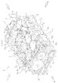
FIG. 1 is a perspective view of a head cover structure, according the present embodiment, for an internal combustion engine; -
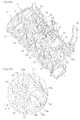
FIGS. 2A and 2B are perspective views showing a state of a head cover in an upward view from below, whereinFIG. 2A is an entire view andFIG. 2B is an enlarged view of portion A shown inFIG.2A ; -
FIG. 3 is a cross-sectional view taken along line I-I shown inFIG. 1 ; and -
FIG. 4 is a cross-sectional view taken along line II-II shown inFIG. 1 . - An embodiment of the present invention will be described below in detail, referring to
FIGS. 1 to 4 . The present embodiment will be described, taking an example of a case of applying the invention to a head cover for the engine of a vehicle. In the description, the same reference number will be assigned to the same elements, and overlapping description will be omitted. In describing directions, description of the directions will be based on front (F), back (B), left (L), and right (R) shown inFIG. 1 . - As shown in
FIG. 1 , an internal combustion engine E is an in-line four cylinder engine of DOHC (Double OverHead Camshaft) type. In addition to ahead cover 1 and acylinder head 2, the basic configuration of the internal combustion engine E includes, though not shown, a cylinder block for housing pistons, connecting rods, cranks, and the like, an oil pan for storing oil, and the like. The internal combustion engine E is transversely installed such that the direction of the row of cylinders is the left/right direction with respect to the vehicle, wherein air is taken in from the back and exhausted from the front. - The
cylinder head 2 is a member forming combustion chambers, intake ports and exhaust ports (not shown). Thecylinder head 2 includes intake valves and exhaust valves (not shown) for opening and closing the intake ports and the exhaust ports respectively, and the upper portion of thecylinder head 2 is provided with avalve train 3 to drive these intake valves and exhaust valves. Further, the side portion of the cylinder head 2 (more concretely, for the internal combustion engine E) is provided with atransmission mechanism 4 for transmitting rotation of the cranks to thevalve train 3. - As shown in
FIG. 4 , thecylinder head 2 includes an outerperipheral wall 21 standing up in a frame shape along the outer peripheral margin of anupper surface 2a, and acentral wall 22 standing up from the central portion with respect to the front/back direction of theupper surface 2a. Further, as shown inFIG. 3 , between the outerperipheral wall 21 and thecentral wall 22, thecylinder head 2 is provided with plural lowerside bearing portions 23 for axially supportingcam shafts valve train 3. The lowerside bearing portions 23 are parts in a wall shape extending along the front/back direction, and have respective recessedportions 23a in a semicircular shape at the central portion of the upper surface thereof. The lowerside bearing portions 23 are provided at positions corresponding to the positions of upperside bearing portion 13 provided on the later-describedhead cover 1. - The
valve train 3 includes the pair ofcam shafts FIG. 4 ) that are fixed respectively to thecam shaft 31 and thecam shaft 32. Thecam shaft 31 is an intake side cam shaft for opening and closing the intake valves, and thecam shaft 32 is an exhaust side cam shaft for opening and closing the exhaust valves. - As shown in
FIGS. 1 to 4 , thehead cover 1 is attached to the upper portion of thecylinder head 2, and is a metal member of an aluminum alloy for covering thevalve train 3. - The
head cover 1 mainly includes acover portion 11 for covering thevalve train 3, an outer peripheralmarginal portion 12 forming the outer peripheral margin of thehead cover 1, and the upperside bearing portions 13 for axially supporting thecam shafts valve train 3. Further, at the central portion with respect to the front/back direction of thehead cover 1, arecessed groove portion 14 is extended along the left/right direction for installing a fuel injection device (not shown). - The outer peripheral
marginal portion 12 is a part in a frame shape provided at the outer peripheral margin of thecover portion 11. The outer peripheralmarginal portion 12 is arranged on the outerperipheral wall 21 provided on the upper surface of thecylinder head 2. The outer peripheralmarginal portion 12 has pluralbolt penetration holes 12a for penetration of bolts B, which are tightening members, and thebolt penetration holes 12a are partially provided between neighboring upperside bearing portions 13. Thesebolt penetration holes 12a correspond to 'outer peripheral side tightening/fixing portion' in claims. Incidentally,bolt tightening holes 21a for tightening the bolts B are formed at positions, the positions corresponding to thebolt penetration holes 12a, of the outer peripheral wall 21 (seeFIG. 4 ). - The upper
side bearing portions 13 are parts for rotatably holding thecam shafts valve train 3 in collaboration with the plural lowerside bearing portions 23 provided at thecylinder head 2. The upperside bearing portions 13 are wall shaped parts extending along the front/back direction and are provided between the outer peripheralmarginal portion 12 and the recessedgroove portion 14, being separated from each other along the left/right direction. The upperside bearing portions 13 are arranged on both the left and right sides of the respective cylinders. Incidentally, in the present embodiment, an upperside bearing portion 13c arranged on the left side of the leftmost cylinder serves also as theleft end portion 12b (seeFIG. 2A ) of the outer peripheralmarginal portion 12. - As shown in
FIGS. 2A, 2B andFIG. 3 , the central portion, with respect to the front/back direction, of the lower surfaces of the upperside bearing portions 13 are provided with respective recessedportions 13a in a semicircular shape. These recessedportions 13a provided on the upperside bearing portions 13 and the respective recessedportions 23a provided on the lowerside bearing portions 23 form the bearing portions, which axially and rotatably support therespective cam shafts portions 13a. These bolt penetration holes 13b correspond to 'bearing side tightening/fixing portion' in claims. Incidentally, the lowerside bearing portions 23 of thecylinder head 2 are provided withbolt tightening holes 23b for tightening bolts B at positions corresponding to thebolt penetration holes 13b. - The
cover portion 11 is a plate shaped part for covering thevalve train 3, and is disposed being separated upward from the valve train 3 (seeFIG. 4 ). Thecover portion 11 has bulgingportions 111 bulging upward in a substantially hemispherical shape between neighboring upperside bearing portions 13. Further, as shown inFIG. 1 , thecover portion 11 hasfirst reinforcement limbs 15 for reinforcing the bulgingportions 111. Thefirst reinforcement limbs 15 are extended such as to stand up between thebolt penetration holes 12a of the outer peripheralmarginal portion 12 and bolt penetration holes 13b of the upperside bearing portions 13, thebolt penetration holes 12a being provided between neighboring upperside bearing portions 13. Thus, the bulgingportions 111 are surrounded by neighboring upperside bearing portions 13 and the first reinforcement limbs, and are thus in a state of being peripherally reinforced. - Incidentally, regarding the bulging
portions 111, it is assumed that 'a substantially hemispherical shape' includes, in addition to a hemispherical shape, a shape that can be recognized to be equal to a hemispherical shape (so-called dome shape, etc.). - As shown in
FIG. 2B , on the lower surface of a bulgingportion 111, second reinforcement limbs16 are radially provided, extending from thetop point 111a of the bulgingportion 111 toward thebolt penetration hole 13b of the upperside bearing portion 13, thebolt penetration hole 12a of the outer peripheralmarginal portion 12, thebolt penetration hole 12a being provided between neighboring upperside bearing portions 13, and the recessedgroove portion 14. Thesecond reinforcement limbs 16 are disposed substantially symmetrically with thetop point 111a as the center. As the bulgingportion 111 is thereby uniformly reinforced, vibration and noise can be reduced. Further, in order to avoid interference with thecam 33, thesecond reinforcement limbs 16 are curved such as to be convex upward along the lower surface of the bulging portion 111 (seeFIG. 4 ). - As shown in
FIG. 1 , acommon rail 5 is attached to the back end portion of thehead cover 1 to supply high pressure fuel to a fuel injection device, not shown. Further, acam angle sensor 6 is attached to the upper surface of thehead cover 1 to detect the rotation angle of thecam shaft 32. Still further, a negative pressure pump 7 is attached to the end portion, on the left side, of thehead cover 1 to supply an operational hydraulic pressure to a valve timing adjustable mechanism (not shown) of thevalve train 3. Yet further, anengine hanger 8 is attached on the left side of the front end portion of thehead cover 1 to hold the internal combustion engine E at a vehicle body frame, not shown. Further, anopening 9 is provided through the upper surface of the right end portion of thehead cover 1 to exhaust blow-by gas to a gas-liquid separation chamber (not shown) provided separately from thehead cover 1. - The head cover structure, for an internal combustion engine, according to the present embodiment is basically configured as described above. The operation and advantage thereof will be described below.
- By the head cover structure according to the present embodiment for an internal combustion engine, the upper
side bearing portions 13 for axially supporting thecam shafts head cover 1, and bulgingportions 111 bulging substantially in a hemispherical shape are formed between neighboring upperside bearing portions 13. Thus, the stiffness of thecover portion 11 is increased by the bulgingportions 111 substantially in a hemispherical shape. Accordingly, it is possible to increase the stiffness of thehead cover 1 as a whole and thereby reduce vibration and noise, while reducing an increase in the thickness and size of thehead cover 1. - Further, in this structure,
first reinforcement limbs 15 are provided between abolt penetration hole 12a of the outer peripheralmarginal portion 12 and bolt penetration holes 13b of upperside bearing portions 13, thebolt penetration hole 12a being provided between the neighboring upperside bearing portions 13; and a bulgingportion 111 is provided at a part surrounded by the neighboring upperside bearing portions 13 and thefirst reinforcement limbs 15. Accordingly, the stiffness of thehead cover 1 is further increased, and it is thereby possible to reduce vibration and noise. - Still further, on the lower surface of the bulging
portion 111, second reinforcement limbs16 are radially provided, extending from thetop point 111a of the bulgingportion 111 toward the bolt penetration holes 13b of the upperside bearing portions 13, thebolt penetration hole 12a of the outer peripheralmarginal portion 12, thebolt penetration hole 12a being provided between the neighboring upperside bearing portions 13, and the recessedgroove portion 14. Accordingly, the stiffness of a bulgingportion 111 can be further increased, and vibration and noise can be further reduced. - Yet further, as
second reinforcement limbs 16 are disposed substantially symmetrically with atop point 111a as the center, a bulgingportion 111 can be uniformly reinforced, and vibration and noise can thereby be reduced. - Further, as the stiffness of the
entire head cover 1 is increased by bulgingportions 111, auxiliary units, such as thecommon rail 5, thecam angle sensor 6, the negative pressure pump 7, theengine hanger 8, and the like can be attached to thehead cover 1. Thus, it is possible to improve the degree of freedom of the layout of the internal combustion engine E. - An embodiment of the present invention has been described in detail, referring to the drawings, however, the invention is not limited thereto, and modifications and changes can be made, as appropriate, in a scope without departing from the spirit of the invention.
- For example, in the present embodiment, the invention is applied to an internal combustion engine E of a so-called DOHC type, however, without being limited thereto, the invention may also be applied to an internal combustion engine, for example, of a SOHC (Single OverHead Camshaft) type.
- Further, in the present embodiment, a gas-liquid separation chamber is separately provided outside the
head cover 1, however, a gas-liquid separation chamber may be provided inside thehead cover 1. Incidentally, in the present embodiment, weight reduction and downsizing of thehead cover 1 can be attained by providing a gas-liquid separation chamber of, for example, a resin separately from thehead cover 1 wherein the gas-liquid separation chamber communicates with theopening 9. - Still further, in the present embodiment, bulging
portion 111 are formed between all neighboring upperside bearing portions 13, however, the invention is not limited thereto, and it is only necessary that bulgingportion 111 are formed at positions, at which reinforcement is necessary, out of positions between all plural neighboring upperside bearing portions 13. -
- 1..
- head cover
- 11..
- cover portion
- 111..
- bulging portion
- 12..
- outer peripheral marginal portion
- 13..
- upper side bearing portion
- 13b..
- bolt penetration hole
- 15..
- first reinforcement limb
- 16..
- second reinforcement limb
- 2..
- cylinder head
- 23..
- lower side bearing portion
- 3..
- valve train
Claims (4)
- A head cover structure for an internal combustion engine, comprising:a cover portion (11) for covering, from an upper side, a valve train including a cam shaft/shafts (31, 32) disposed at a cylinder head (2);an outer peripheral marginal portion (12) provided along an outer peripheral margin of the cover portion (11) and tightened to the cylinder head (2); anda plurality of upper side bearing portions (13) provided integrally with the cover portion (11) and the outer peripheral marginal portion (12) to rotatably hold the cam shaft/shafts (31, 32) in collaboration with a plurality of lower side bearing portions (23) provided on the cylinder head (2),wherein the upper side bearing portions (13) are tightened and fixed to the lower side bearing portions (23),and wherein the cover portion (13) includes bulging portions (111), characterized in that said bulging portions substantially bulge in a hemispherical shape between neighboring ones of the upper side bearing portions (13) .
- The head cover structure for an internal combustion engine according to claim 1,
wherein the upper side bearing portions (13) include bearing side tightening/fixing portions (13b) tightened and fixed to the lower bearing portions,
wherein the outer peripheral marginal portion (12) includes outer peripheral side tightening/fixing portions (12a) at middle parts between neighboring ones of the upper side bearing portions (13), the outer peripheral side tightening/fixing portions (12a) being tightened and fixed to the cylinder head (2),
wherein first reinforcement limbs (15) are provided between the bearing side tightening/fixing portions and the outer peripheral side tightening/fixing portions,
and wherein the bulging portions (111) are provided at parts surrounded by neighboring ones of the upper side bearing portions (13) and the first reinforcement limbs (15). - The head cover structure for an internal combustion engine according to claim 2,
wherein second reinforcement limbs (16) are provided on lower surfaces of the bulging portions (111), extending from top points of the bulging portions (15) toward the bearing side tightening/fixing portions and the outer peripheral side tightening/fixing portions. - The head cover structure for an internal combustion engine according to any one of claims 1 to 3,
wherein the cam shafts (31,32) include an intake side cam shaft (31) and an exhaust side cam shaft (32),
wherein the upper side bearing portions (13) are disposed in a plural number respectively along the intake side cam shaft (31) and the exhaust side cam shaft (32),
and wherein the bulging portions (111) are provided at least between the upper side bearing portions (13) along the intake side cam shaft (31) or between the upper side bearing (13) portions along the exhaust side cam shaft (32).
Applications Claiming Priority (2)
| Application Number | Priority Date | Filing Date | Title |
|---|---|---|---|
| JP2011035549 | 2011-02-22 | ||
| PCT/JP2012/054185 WO2012115123A1 (en) | 2011-02-22 | 2012-02-22 | Internal combustion engine head-cover structure |
Publications (3)
| Publication Number | Publication Date |
|---|---|
| EP2679792A1 EP2679792A1 (en) | 2014-01-01 |
| EP2679792A4 EP2679792A4 (en) | 2014-11-19 |
| EP2679792B1 true EP2679792B1 (en) | 2016-01-20 |
Family
ID=46720899
Family Applications (1)
| Application Number | Title | Priority Date | Filing Date |
|---|---|---|---|
| EP12749912.7A Not-in-force EP2679792B1 (en) | 2011-02-22 | 2012-02-22 | Internal combustion engine head-cover structure |
Country Status (4)
| Country | Link |
|---|---|
| EP (1) | EP2679792B1 (en) |
| JP (1) | JP5581438B2 (en) |
| CN (1) | CN103403332B (en) |
| WO (1) | WO2012115123A1 (en) |
Families Citing this family (4)
| Publication number | Priority date | Publication date | Assignee | Title |
|---|---|---|---|---|
| JP2015124730A (en) * | 2013-12-27 | 2015-07-06 | 株式会社マーレ フィルターシステムズ | Cover member |
| FR3026789B1 (en) * | 2014-10-02 | 2016-11-04 | Renault Sa | INTERNAL COMBUSTION ENGINE HEAD COVER |
| JP6631176B2 (en) * | 2015-11-09 | 2020-01-15 | いすゞ自動車株式会社 | Cylinder head structure of internal combustion engine and internal combustion engine |
| DE102021201823A1 (en) * | 2021-02-26 | 2022-09-01 | Mahle International Gmbh | cylinder head cover |
Family Cites Families (10)
| Publication number | Priority date | Publication date | Assignee | Title |
|---|---|---|---|---|
| JP2958722B2 (en) * | 1991-09-03 | 1999-10-06 | ヤマハ発動機株式会社 | Cylinder head cover structure of internal combustion engine |
| DE4323073A1 (en) * | 1993-07-10 | 1995-01-12 | Audi Ag | Reciprocating piston internal combustion engine |
| DE20120912U1 (en) * | 2001-12-24 | 2002-06-06 | Volkswagen Ag | Cylinder head cover for an internal combustion engine |
| FR2867520B1 (en) * | 2004-03-09 | 2006-05-05 | Renault Sas | INTERNAL COMBUSTION ENGINE WITH AN ENCLOSURE FOR CONTAINING FUEL LEAKS |
| JP4365373B2 (en) * | 2006-01-19 | 2009-11-18 | トヨタ自動車株式会社 | Camshaft support structure for internal combustion engine |
| JP2008057406A (en) * | 2006-08-30 | 2008-03-13 | Toyota Motor Corp | Camshaft support structure for internal combustion engine |
| US7654237B2 (en) * | 2007-01-23 | 2010-02-02 | Lanxess Corporation | Cam cover |
| CN201206478Y (en) * | 2008-04-22 | 2009-03-11 | 奇瑞汽车股份有限公司 | Cam spindle frame for engine |
| DE202008013310U1 (en) * | 2008-10-07 | 2009-02-12 | Reinz-Dichtungs-Gmbh | Cylinder head cover with metallic coating of seats for oil control valves |
| US8065993B2 (en) * | 2008-12-16 | 2011-11-29 | Ford Global Technologies, Llc | Structural oil baffle for engine covers |
-
2012
- 2012-02-22 JP JP2013501082A patent/JP5581438B2/en not_active Expired - Fee Related
- 2012-02-22 EP EP12749912.7A patent/EP2679792B1/en not_active Not-in-force
- 2012-02-22 WO PCT/JP2012/054185 patent/WO2012115123A1/en active Application Filing
- 2012-02-22 CN CN201280010029.7A patent/CN103403332B/en active Active
Also Published As
| Publication number | Publication date |
|---|---|
| EP2679792A1 (en) | 2014-01-01 |
| EP2679792A4 (en) | 2014-11-19 |
| WO2012115123A1 (en) | 2012-08-30 |
| JPWO2012115123A1 (en) | 2014-07-07 |
| JP5581438B2 (en) | 2014-08-27 |
| CN103403332A (en) | 2013-11-20 |
| CN103403332B (en) | 2015-11-25 |
Similar Documents
| Publication | Publication Date | Title |
|---|---|---|
| US7913660B2 (en) | Cylinder head | |
| EP2679792B1 (en) | Internal combustion engine head-cover structure | |
| US20090084341A1 (en) | Cylinder head | |
| CA2317159C (en) | Construction for a cam rotation sensor attaching portion | |
| JPH0219523Y2 (en) | ||
| WO2010096187A3 (en) | Multi-cylinder opposed piston engines | |
| GB2269855A (en) | I.c. engine cylinder head camshaft bearing cap and rocker shaft support unit. | |
| JP5779222B2 (en) | Oil control valve holding structure | |
| JP6237175B2 (en) | engine | |
| JP2011169272A (en) | Cylinder head structure in multi-cylinder internal combustion engine | |
| US8534251B2 (en) | Engine assembly with camshaft housing | |
| EP3375991B1 (en) | Cylinder head for internal combustion engine and internal combustion engine | |
| US9316151B2 (en) | Engine assembly including crankshaft for V8 arrangement | |
| KR20090077708A (en) | Cam shaft and manufacturing method for the same | |
| JP4210279B2 (en) | Bearing cap structure | |
| US20120234270A1 (en) | Engine assembly including crankshaft for v4 arrangement | |
| EP2767680A1 (en) | Camshaft support structure | |
| CN217421372U (en) | Shaft cover structure of engine camshaft | |
| JP6686417B2 (en) | engine | |
| JP2013113158A (en) | Head cover structure of internal combustion engine | |
| US10267259B2 (en) | Cylinder head with valve deactivators | |
| JP5097071B2 (en) | Bearing cap structure | |
| JP6686416B2 (en) | engine | |
| JP2008101491A (en) | Engine and motorcycle | |
| JP2018031260A (en) | cylinder head |
Legal Events
| Date | Code | Title | Description |
|---|---|---|---|
| PUAI | Public reference made under article 153(3) epc to a published international application that has entered the european phase |
Free format text: ORIGINAL CODE: 0009012 |
|
| 17P | Request for examination filed |
Effective date: 20130920 |
|
| AK | Designated contracting states |
Kind code of ref document: A1 Designated state(s): AL AT BE BG CH CY CZ DE DK EE ES FI FR GB GR HR HU IE IS IT LI LT LU LV MC MK MT NL NO PL PT RO RS SE SI SK SM TR |
|
| DAX | Request for extension of the european patent (deleted) | ||
| A4 | Supplementary search report drawn up and despatched |
Effective date: 20141022 |
|
| RIC1 | Information provided on ipc code assigned before grant |
Ipc: F02F 7/00 20060101AFI20141016BHEP |
|
| GRAP | Despatch of communication of intention to grant a patent |
Free format text: ORIGINAL CODE: EPIDOSNIGR1 |
|
| GRAJ | Information related to disapproval of communication of intention to grant by the applicant or resumption of examination proceedings by the epo deleted |
Free format text: ORIGINAL CODE: EPIDOSDIGR1 |
|
| GRAP | Despatch of communication of intention to grant a patent |
Free format text: ORIGINAL CODE: EPIDOSNIGR1 |
|
| INTG | Intention to grant announced |
Effective date: 20150702 |
|
| INTG | Intention to grant announced |
Effective date: 20150715 |
|
| GRAS | Grant fee paid |
Free format text: ORIGINAL CODE: EPIDOSNIGR3 |
|
| GRAA | (expected) grant |
Free format text: ORIGINAL CODE: 0009210 |
|
| AK | Designated contracting states |
Kind code of ref document: B1 Designated state(s): AL AT BE BG CH CY CZ DE DK EE ES FI FR GB GR HR HU IE IS IT LI LT LU LV MC MK MT NL NO PL PT RO RS SE SI SK SM TR |
|
| REG | Reference to a national code |
Ref country code: GB Ref legal event code: FG4D |
|
| REG | Reference to a national code |
Ref country code: CH Ref legal event code: EP |
|
| REG | Reference to a national code |
Ref country code: IE Ref legal event code: FG4D |
|
| REG | Reference to a national code |
Ref country code: AT Ref legal event code: REF Ref document number: 771845 Country of ref document: AT Kind code of ref document: T Effective date: 20160215 |
|
| REG | Reference to a national code |
Ref country code: DE Ref legal event code: R096 Ref document number: 602012014156 Country of ref document: DE |
|
| REG | Reference to a national code |
Ref country code: LT Ref legal event code: MG4D Ref country code: NL Ref legal event code: MP Effective date: 20160120 |
|
| PG25 | Lapsed in a contracting state [announced via postgrant information from national office to epo] |
Ref country code: BE Free format text: LAPSE BECAUSE OF NON-PAYMENT OF DUE FEES Effective date: 20160229 |
|
| REG | Reference to a national code |
Ref country code: AT Ref legal event code: MK05 Ref document number: 771845 Country of ref document: AT Kind code of ref document: T Effective date: 20160120 |
|
| PG25 | Lapsed in a contracting state [announced via postgrant information from national office to epo] |
Ref country code: NL Free format text: LAPSE BECAUSE OF FAILURE TO SUBMIT A TRANSLATION OF THE DESCRIPTION OR TO PAY THE FEE WITHIN THE PRESCRIBED TIME-LIMIT Effective date: 20160120 |
|
| PG25 | Lapsed in a contracting state [announced via postgrant information from national office to epo] |
Ref country code: IT Free format text: LAPSE BECAUSE OF FAILURE TO SUBMIT A TRANSLATION OF THE DESCRIPTION OR TO PAY THE FEE WITHIN THE PRESCRIBED TIME-LIMIT Effective date: 20160120 Ref country code: NO Free format text: LAPSE BECAUSE OF FAILURE TO SUBMIT A TRANSLATION OF THE DESCRIPTION OR TO PAY THE FEE WITHIN THE PRESCRIBED TIME-LIMIT Effective date: 20160420 Ref country code: HR Free format text: LAPSE BECAUSE OF FAILURE TO SUBMIT A TRANSLATION OF THE DESCRIPTION OR TO PAY THE FEE WITHIN THE PRESCRIBED TIME-LIMIT Effective date: 20160120 Ref country code: FI Free format text: LAPSE BECAUSE OF FAILURE TO SUBMIT A TRANSLATION OF THE DESCRIPTION OR TO PAY THE FEE WITHIN THE PRESCRIBED TIME-LIMIT Effective date: 20160120 Ref country code: GR Free format text: LAPSE BECAUSE OF FAILURE TO SUBMIT A TRANSLATION OF THE DESCRIPTION OR TO PAY THE FEE WITHIN THE PRESCRIBED TIME-LIMIT Effective date: 20160421 Ref country code: ES Free format text: LAPSE BECAUSE OF FAILURE TO SUBMIT A TRANSLATION OF THE DESCRIPTION OR TO PAY THE FEE WITHIN THE PRESCRIBED TIME-LIMIT Effective date: 20160120 |
|
| PG25 | Lapsed in a contracting state [announced via postgrant information from national office to epo] |
Ref country code: AT Free format text: LAPSE BECAUSE OF FAILURE TO SUBMIT A TRANSLATION OF THE DESCRIPTION OR TO PAY THE FEE WITHIN THE PRESCRIBED TIME-LIMIT Effective date: 20160120 Ref country code: PT Free format text: LAPSE BECAUSE OF FAILURE TO SUBMIT A TRANSLATION OF THE DESCRIPTION OR TO PAY THE FEE WITHIN THE PRESCRIBED TIME-LIMIT Effective date: 20160520 Ref country code: LV Free format text: LAPSE BECAUSE OF FAILURE TO SUBMIT A TRANSLATION OF THE DESCRIPTION OR TO PAY THE FEE WITHIN THE PRESCRIBED TIME-LIMIT Effective date: 20160120 Ref country code: SE Free format text: LAPSE BECAUSE OF FAILURE TO SUBMIT A TRANSLATION OF THE DESCRIPTION OR TO PAY THE FEE WITHIN THE PRESCRIBED TIME-LIMIT Effective date: 20160120 Ref country code: RS Free format text: LAPSE BECAUSE OF FAILURE TO SUBMIT A TRANSLATION OF THE DESCRIPTION OR TO PAY THE FEE WITHIN THE PRESCRIBED TIME-LIMIT Effective date: 20160120 Ref country code: IS Free format text: LAPSE BECAUSE OF FAILURE TO SUBMIT A TRANSLATION OF THE DESCRIPTION OR TO PAY THE FEE WITHIN THE PRESCRIBED TIME-LIMIT Effective date: 20160520 Ref country code: LT Free format text: LAPSE BECAUSE OF FAILURE TO SUBMIT A TRANSLATION OF THE DESCRIPTION OR TO PAY THE FEE WITHIN THE PRESCRIBED TIME-LIMIT Effective date: 20160120 Ref country code: PL Free format text: LAPSE BECAUSE OF FAILURE TO SUBMIT A TRANSLATION OF THE DESCRIPTION OR TO PAY THE FEE WITHIN THE PRESCRIBED TIME-LIMIT Effective date: 20160120 |
|
| REG | Reference to a national code |
Ref country code: CH Ref legal event code: PL |
|
| REG | Reference to a national code |
Ref country code: DE Ref legal event code: R097 Ref document number: 602012014156 Country of ref document: DE |
|
| PG25 | Lapsed in a contracting state [announced via postgrant information from national office to epo] |
Ref country code: EE Free format text: LAPSE BECAUSE OF FAILURE TO SUBMIT A TRANSLATION OF THE DESCRIPTION OR TO PAY THE FEE WITHIN THE PRESCRIBED TIME-LIMIT Effective date: 20160120 Ref country code: MC Free format text: LAPSE BECAUSE OF FAILURE TO SUBMIT A TRANSLATION OF THE DESCRIPTION OR TO PAY THE FEE WITHIN THE PRESCRIBED TIME-LIMIT Effective date: 20160120 Ref country code: DK Free format text: LAPSE BECAUSE OF FAILURE TO SUBMIT A TRANSLATION OF THE DESCRIPTION OR TO PAY THE FEE WITHIN THE PRESCRIBED TIME-LIMIT Effective date: 20160120 Ref country code: LI Free format text: LAPSE BECAUSE OF NON-PAYMENT OF DUE FEES Effective date: 20160229 Ref country code: CH Free format text: LAPSE BECAUSE OF NON-PAYMENT OF DUE FEES Effective date: 20160229 |
|
| PLBE | No opposition filed within time limit |
Free format text: ORIGINAL CODE: 0009261 |
|
| REG | Reference to a national code |
Ref country code: FR Ref legal event code: ST Effective date: 20161028 |
|
| STAA | Information on the status of an ep patent application or granted ep patent |
Free format text: STATUS: NO OPPOSITION FILED WITHIN TIME LIMIT |
|
| PG25 | Lapsed in a contracting state [announced via postgrant information from national office to epo] |
Ref country code: CZ Free format text: LAPSE BECAUSE OF FAILURE TO SUBMIT A TRANSLATION OF THE DESCRIPTION OR TO PAY THE FEE WITHIN THE PRESCRIBED TIME-LIMIT Effective date: 20160120 Ref country code: SK Free format text: LAPSE BECAUSE OF FAILURE TO SUBMIT A TRANSLATION OF THE DESCRIPTION OR TO PAY THE FEE WITHIN THE PRESCRIBED TIME-LIMIT Effective date: 20160120 Ref country code: RO Free format text: LAPSE BECAUSE OF FAILURE TO SUBMIT A TRANSLATION OF THE DESCRIPTION OR TO PAY THE FEE WITHIN THE PRESCRIBED TIME-LIMIT Effective date: 20160120 Ref country code: SM Free format text: LAPSE BECAUSE OF FAILURE TO SUBMIT A TRANSLATION OF THE DESCRIPTION OR TO PAY THE FEE WITHIN THE PRESCRIBED TIME-LIMIT Effective date: 20160120 |
|
| REG | Reference to a national code |
Ref country code: IE Ref legal event code: MM4A |
|
| 26N | No opposition filed |
Effective date: 20161021 |
|
| PG25 | Lapsed in a contracting state [announced via postgrant information from national office to epo] |
Ref country code: BE Free format text: LAPSE BECAUSE OF FAILURE TO SUBMIT A TRANSLATION OF THE DESCRIPTION OR TO PAY THE FEE WITHIN THE PRESCRIBED TIME-LIMIT Effective date: 20160120 |
|
| PG25 | Lapsed in a contracting state [announced via postgrant information from national office to epo] |
Ref country code: FR Free format text: LAPSE BECAUSE OF NON-PAYMENT OF DUE FEES Effective date: 20160321 Ref country code: IE Free format text: LAPSE BECAUSE OF NON-PAYMENT OF DUE FEES Effective date: 20160222 |
|
| PG25 | Lapsed in a contracting state [announced via postgrant information from national office to epo] |
Ref country code: SI Free format text: LAPSE BECAUSE OF FAILURE TO SUBMIT A TRANSLATION OF THE DESCRIPTION OR TO PAY THE FEE WITHIN THE PRESCRIBED TIME-LIMIT Effective date: 20160120 Ref country code: BG Free format text: LAPSE BECAUSE OF FAILURE TO SUBMIT A TRANSLATION OF THE DESCRIPTION OR TO PAY THE FEE WITHIN THE PRESCRIBED TIME-LIMIT Effective date: 20160420 |
|
| REG | Reference to a national code |
Ref country code: DE Ref legal event code: R084 Ref document number: 602012014156 Country of ref document: DE |
|
| PG25 | Lapsed in a contracting state [announced via postgrant information from national office to epo] |
Ref country code: MT Free format text: LAPSE BECAUSE OF FAILURE TO SUBMIT A TRANSLATION OF THE DESCRIPTION OR TO PAY THE FEE WITHIN THE PRESCRIBED TIME-LIMIT Effective date: 20160120 |
|
| REG | Reference to a national code |
Ref country code: GB Ref legal event code: 746 Effective date: 20170815 |
|
| PG25 | Lapsed in a contracting state [announced via postgrant information from national office to epo] |
Ref country code: HU Free format text: LAPSE BECAUSE OF FAILURE TO SUBMIT A TRANSLATION OF THE DESCRIPTION OR TO PAY THE FEE WITHIN THE PRESCRIBED TIME-LIMIT; INVALID AB INITIO Effective date: 20120222 Ref country code: CY Free format text: LAPSE BECAUSE OF FAILURE TO SUBMIT A TRANSLATION OF THE DESCRIPTION OR TO PAY THE FEE WITHIN THE PRESCRIBED TIME-LIMIT Effective date: 20160120 |
|
| PG25 | Lapsed in a contracting state [announced via postgrant information from national office to epo] |
Ref country code: MT Free format text: LAPSE BECAUSE OF FAILURE TO SUBMIT A TRANSLATION OF THE DESCRIPTION OR TO PAY THE FEE WITHIN THE PRESCRIBED TIME-LIMIT Effective date: 20160229 Ref country code: LU Free format text: LAPSE BECAUSE OF NON-PAYMENT OF DUE FEES Effective date: 20160222 Ref country code: TR Free format text: LAPSE BECAUSE OF FAILURE TO SUBMIT A TRANSLATION OF THE DESCRIPTION OR TO PAY THE FEE WITHIN THE PRESCRIBED TIME-LIMIT Effective date: 20160120 Ref country code: MK Free format text: LAPSE BECAUSE OF FAILURE TO SUBMIT A TRANSLATION OF THE DESCRIPTION OR TO PAY THE FEE WITHIN THE PRESCRIBED TIME-LIMIT Effective date: 20160120 |
|
| PG25 | Lapsed in a contracting state [announced via postgrant information from national office to epo] |
Ref country code: AL Free format text: LAPSE BECAUSE OF FAILURE TO SUBMIT A TRANSLATION OF THE DESCRIPTION OR TO PAY THE FEE WITHIN THE PRESCRIBED TIME-LIMIT Effective date: 20160120 |
|
| PGFP | Annual fee paid to national office [announced via postgrant information from national office to epo] |
Ref country code: GB Payment date: 20190220 Year of fee payment: 8 Ref country code: DE Payment date: 20190212 Year of fee payment: 8 |
|
| REG | Reference to a national code |
Ref country code: DE Ref legal event code: R119 Ref document number: 602012014156 Country of ref document: DE |
|
| GBPC | Gb: european patent ceased through non-payment of renewal fee |
Effective date: 20200222 |
|
| PG25 | Lapsed in a contracting state [announced via postgrant information from national office to epo] |
Ref country code: GB Free format text: LAPSE BECAUSE OF NON-PAYMENT OF DUE FEES Effective date: 20200222 Ref country code: DE Free format text: LAPSE BECAUSE OF NON-PAYMENT OF DUE FEES Effective date: 20200901 |