WO2012114981A1 - ボイラプラントおよびその運転方法 - Google Patents
ボイラプラントおよびその運転方法 Download PDFInfo
- Publication number
- WO2012114981A1 WO2012114981A1 PCT/JP2012/053716 JP2012053716W WO2012114981A1 WO 2012114981 A1 WO2012114981 A1 WO 2012114981A1 JP 2012053716 W JP2012053716 W JP 2012053716W WO 2012114981 A1 WO2012114981 A1 WO 2012114981A1
- Authority
- WO
- WIPO (PCT)
- Prior art keywords
- hot water
- exhaust gas
- temperature
- boiler
- flow rate
- Prior art date
- Legal status (The legal status is an assumption and is not a legal conclusion. Google has not performed a legal analysis and makes no representation as to the accuracy of the status listed.)
- Ceased
Links
Images


Classifications
-
- F—MECHANICAL ENGINEERING; LIGHTING; HEATING; WEAPONS; BLASTING
- F23—COMBUSTION APPARATUS; COMBUSTION PROCESSES
- F23L—SUPPLYING AIR OR NON-COMBUSTIBLE LIQUIDS OR GASES TO COMBUSTION APPARATUS IN GENERAL ; VALVES OR DAMPERS SPECIALLY ADAPTED FOR CONTROLLING AIR SUPPLY OR DRAUGHT IN COMBUSTION APPARATUS; INDUCING DRAUGHT IN COMBUSTION APPARATUS; TOPS FOR CHIMNEYS OR VENTILATING SHAFTS; TERMINALS FOR FLUES
- F23L15/00—Heating of air supplied for combustion
- F23L15/04—Arrangements of recuperators
- F23L15/045—Arrangements of recuperators using intermediate heat-transfer fluids
-
- F—MECHANICAL ENGINEERING; LIGHTING; HEATING; WEAPONS; BLASTING
- F22—STEAM GENERATION
- F22D—PREHEATING, OR ACCUMULATING PREHEATED, FEED-WATER FOR STEAM GENERATION; FEED-WATER SUPPLY FOR STEAM GENERATION; CONTROLLING WATER LEVEL FOR STEAM GENERATION; AUXILIARY DEVICES FOR PROMOTING WATER CIRCULATION WITHIN STEAM BOILERS
- F22D1/00—Feed-water heaters, i.e. economisers or like preheaters
- F22D1/003—Feed-water heater systems
-
- F—MECHANICAL ENGINEERING; LIGHTING; HEATING; WEAPONS; BLASTING
- F22—STEAM GENERATION
- F22D—PREHEATING, OR ACCUMULATING PREHEATED, FEED-WATER FOR STEAM GENERATION; FEED-WATER SUPPLY FOR STEAM GENERATION; CONTROLLING WATER LEVEL FOR STEAM GENERATION; AUXILIARY DEVICES FOR PROMOTING WATER CIRCULATION WITHIN STEAM BOILERS
- F22D1/00—Feed-water heaters, i.e. economisers or like preheaters
- F22D1/36—Water and air preheating systems
-
- F—MECHANICAL ENGINEERING; LIGHTING; HEATING; WEAPONS; BLASTING
- F22—STEAM GENERATION
- F22D—PREHEATING, OR ACCUMULATING PREHEATED, FEED-WATER FOR STEAM GENERATION; FEED-WATER SUPPLY FOR STEAM GENERATION; CONTROLLING WATER LEVEL FOR STEAM GENERATION; AUXILIARY DEVICES FOR PROMOTING WATER CIRCULATION WITHIN STEAM BOILERS
- F22D1/00—Feed-water heaters, i.e. economisers or like preheaters
- F22D1/50—Feed-water heaters, i.e. economisers or like preheaters incorporating thermal de-aeration of feed-water
-
- Y—GENERAL TAGGING OF NEW TECHNOLOGICAL DEVELOPMENTS; GENERAL TAGGING OF CROSS-SECTIONAL TECHNOLOGIES SPANNING OVER SEVERAL SECTIONS OF THE IPC; TECHNICAL SUBJECTS COVERED BY FORMER USPC CROSS-REFERENCE ART COLLECTIONS [XRACs] AND DIGESTS
- Y02—TECHNOLOGIES OR APPLICATIONS FOR MITIGATION OR ADAPTATION AGAINST CLIMATE CHANGE
- Y02E—REDUCTION OF GREENHOUSE GAS [GHG] EMISSIONS, RELATED TO ENERGY GENERATION, TRANSMISSION OR DISTRIBUTION
- Y02E20/00—Combustion technologies with mitigation potential
- Y02E20/34—Indirect CO2mitigation, i.e. by acting on non CO2directly related matters of the process, e.g. pre-heating or heat recovery
Definitions
- the present invention relates to a boiler plant and an operation method thereof.
- waste heat is recovered using an exhaust gas economizer that heats feed water with combustion exhaust gas in order to increase thermal efficiency. Further, in order to improve combustion efficiency, the combustion air is heated and supplied in advance by a preheater.
- a preheater for example, as shown in Patent Document 1, heat exchange is performed between combustion air and combustion exhaust gas, and waste heat of combustion exhaust gas is recovered together with preheating of combustion air.
- SAH Steam Air Heater
- GAH Gas Air Heater
- a combination of GAH and SAH is also used.
- GAH can collect
- SAH has a lower boiler efficiency than GAH because waste heat recovery of combustion exhaust gas is performed only by an exhaust gas economizer.
- the exhaust gas economizer sets the outlet combustion exhaust gas temperature to about 140 ° C. from the viewpoint of sulfuric acid corrosion, so that the boiler efficiency is about 2-3% lower than GAH.
- the structure of SAH is simple, it is inexpensive and has good operability and maintainability.
- GAH has good boiler efficiency
- the structure is complicated and large.
- it is necessary to suppress the heat absorption by the exhaust gas economizer, so that the amount of the suppressed amount of heat is secured in the water supply system. That is, in order to ensure the feed water temperature to the boiler, a so-called four-stage feed water supply system water supply system in which a plurality of high-pressure feed water heaters are provided after the deaerator. Therefore, the boiler plant has a complicated structure and is increased in size, resulting in an increase in manufacturing cost and a decrease in operability and maintainability.
- GAH and high-pressure feed water heaters are expensive members, and GAH requires replacement of members every few years due to concerns about clogging due to sulfuric acid corrosion and soot. Repair requires significant maintenance costs.
- SAH has a relatively simple structure, is inexpensive, and has good operability and maintainability, but has a problem that boiler efficiency is lower than GAH.
- neither GAH nor SAH has a function of controlling the temperature of combustion air and combustion exhaust gas at the outlet. That is, in the GAH, these temperatures are determined by the performance of the GAH itself, the load on the boiler, the outside air temperature, etc., so that the fluctuation range is large and the intended performance may not be exhibited depending on the situation. In SAH, these temperatures are determined by the performance of the heat exchanger, the load on the boiler, the outside air temperature, etc., so the fluctuation range is large, and the desired performance may not be exhibited depending on the situation. For example, depending on the situation of the boiler load, the fuel used, etc., there is a concern that the outlet temperature of the combustion exhaust gas is unexpectedly lowered and sulfuric acid corrosion occurs.
- an object of the present invention is to provide a boiler plant capable of improving efficiency with a simple structure and capable of reliably recovering waste heat from combustion exhaust gas and heating combustion air and an operation method thereof.
- the present invention employs the following means. That is, according to the first aspect of the present invention, the hot water is divided from the middle of the water supply system to the boiler and then joined to the water supply system, the circulation flow path is provided in the circulation flow path, and combustion air and heat A hot water heating air preheater to be exchanged, a hot water heater provided on the downstream side of the hot water heating air flow direction in the hot water flow direction to exchange heat with the combustion exhaust gas of the boiler, and the hot water flowing through the circulation channel A flow rate adjusting means for adjusting the flow rate of the hot water, a hot water temperature detector for detecting the hot water temperature from the hot water heating type air preheater, and an exhaust gas temperature of the combustion exhaust gas from the hot water heater.
- the exhaust gas temperature detector and the hot water temperature are lower than the first predetermined temperature, and the exhaust gas temperature is higher than the second predetermined temperature set higher than the first predetermined temperature. Adjusting the flow rate adjusting means before A control unit for controlling the hot water flow rate, a boiler plant is provided.
- the condensed water is heated by a low-temperature feed water heater and a deaerator to be warm water.
- this hot water is circulated through the circulation channel, and first, the hot water is heat-exchanged with the combustion air in the hot water heating type air preheater. That is, the hot water heats and raises the temperature of the combustion air and is cooled by the combustion air.
- the temperature drop at this time depends on the flow rate of the hot water. That is, the temperature drop is small when the flow rate is large, and the temperature drop is large when the flow rate is small.
- the combustion air is heated by the hot water heating type air preheater and supplied to the boiler, so that the combustion efficiency of the fuel can be improved.
- the hot water cooled by the combustion air is heat-exchanged with the combustion exhaust gas of the boiler by the hot water heater, cools the combustion exhaust gas, and is heated by the combustion exhaust gas.
- the hot water heating air preheater gives heat to the combustion air
- the hot water heater recovers the heat from the combustion exhaust gas.
- the temperature drop of the combustion exhaust gas at this time depends on the flow rate of hot water. That is, if the flow rate is large, the cooling is larger, so that the temperature drop is large, and if it is small, the temperature drop is small.
- the waste heat of combustion exhaust gas is collect
- the efficiency of a boiler plant can be improved.
- heat amount supplied with the warm water heating type air preheater with the warm water heater is returned to a water supply system. Therefore, the influence on the water supply system can be minimized. Since the hot water heating type air preheater and the hot water heater perform heat exchange between the liquid and the gas, and a high heat transmissivity is obtained, the structure is simple and the size can be reduced.
- the control unit adjusts the flow rate of the warm water so that the warm water temperature of the warm water exiting the warm water heating air preheater is lower than the first predetermined temperature
- the warm water heater is The exhaust gas temperature of the combustion exhaust gas that comes out is made higher than the second predetermined temperature. Since the second set temperature is set higher than the first predetermined temperature, the temperature of the combustion exhaust gas entering the hot water heater is higher than the difference between the second predetermined temperature and the first predetermined temperature than the temperature of the hot water. . Therefore, since a temperature difference is surely generated between the combustion exhaust gas and the hot water, heat exchange is established, and the hot water can reliably recover the waste heat of the combustion exhaust gas with the hot water heater.
- the setting of the second predetermined temperature for example, by setting the temperature so as to suppress the occurrence of sulfuric acid corrosion, even if fuel containing a large amount of sulfur is used, the occurrence of sulfuric acid corrosion is suppressed. Can do. Moreover, since the hot water temperature of the hot water exiting the hot water heating air preheater is made lower than the first predetermined temperature, it is possible to prevent the combustion air from being given an excessive amount of heat and raising the temperature more than necessary. , It leads to energy saving.
- the flow rate adjusting means may be a three-way regulating valve configured to return a part of the hot water to the water supply system.
- the control unit adjusts three-way when the warm water temperature of the warm water exiting the warm water heating air preheater becomes higher than the first predetermined temperature, or the exhaust gas temperature of the combustion exhaust gas leaving the hot water heater is lower than the second predetermined temperature. Operate the valve to return part of the hot water to the water supply system.
- the amount of hot water supplied to the hot water heating type air preheater or the like is reduced, so the amount of heat of the hot water is reduced, and the temperature of the hot water exiting the hot water heating type air preheater is lowered, or The exhaust gas temperature of the combustion exhaust gas that has left the chamber increases.
- the flow rate adjusting means may be constituted by a pump having a variable supply capacity and an inverter for adjusting the supply capacity of the pump.
- the control unit A control signal is issued to reduce the pump supply capacity.
- the amount of hot water supplied to the hot water heating type air preheater or the like is reduced, so the amount of heat of the hot water is reduced, and the temperature of the hot water exiting the hot water heating type air preheater is lowered, or the hot water heater
- the exhaust gas temperature of the combustion exhaust gas that has left the chamber increases.
- the second aspect of the present invention is a method in which hot water is diverted from the middle of a water supply system to a boiler and then merged with the water supply system, and the hot water provided in the circulation flow channel and exchanges heat with combustion air.
- a flow rate adjusting means for adjusting the boiler plant, wherein the temperature of the hot water exiting the hot water heating air preheater and the exhaust gas temperature of the combustion exhaust gas exiting the hot water heater are detected.
- the condensed water is heated by a low-temperature feed water heater and a deaerator to be warm water.
- this hot water is circulated through the circulation flow path, and first, the hot water is heat-exchanged with the combustion air by the hot water heating type air preheater. That is, the hot water heats and raises the temperature of the combustion air and is cooled by the combustion air.
- the temperature drop at this time depends on the flow rate of the hot water. That is, the temperature drop is small when the flow rate is large, and the temperature drop is large when the flow rate is small.
- the combustion air is heated by the hot water heating type air preheater and supplied to the boiler, so that the combustion efficiency of the fuel can be improved.
- the hot water cooled by the combustion air is heat-exchanged with the combustion exhaust gas of the boiler by the hot water heater, cools the combustion exhaust gas, and is heated by the combustion exhaust gas.
- the hot water heating air preheater gives heat to the combustion air
- the hot water heater recovers the heat from the combustion exhaust gas.
- the temperature drop of the combustion exhaust gas at this time depends on the flow rate of hot water. That is, if the flow rate is large, the cooling is larger, so that the temperature drop is large, and if it is small, the temperature drop is small.
- the waste heat of combustion exhaust gas is collect
- the flow rate of the warm water is adjusted so that the warm water temperature of the warm water exiting the warm water heating air preheater is lower than the first predetermined temperature, and the combustion exhaust gas exiting the warm water heater
- the exhaust gas temperature is higher than the second predetermined temperature. Since the second set temperature is set higher than the first predetermined temperature, the temperature of the combustion exhaust gas entering the hot water heater is higher than the difference between the second predetermined temperature and the first predetermined temperature than the temperature of the hot water. . Therefore, since there is a certain temperature difference between the combustion exhaust gas and the hot water, heat exchange is established, and the warm water can reliably recover the waste heat of the combustion exhaust gas with the hot water heater.
- the setting of the second predetermined temperature for example, by setting the temperature so as to suppress the occurrence of sulfuric acid corrosion, even if fuel containing a large amount of sulfur is used, the occurrence of sulfuric acid corrosion is suppressed. Can do. Moreover, since the hot water temperature of the hot water exiting the hot water heating air preheater is made lower than the first predetermined temperature, it is possible to prevent the combustion air from being given an excessive amount of heat and raising the temperature more than necessary. , Leading to energy saving.
- the structure for performing the air preheating is simple, the efficiency can be improved, and the waste heat recovery of the combustion exhaust gas and the heating of the combustion air can be reliably performed.
- FIG. 1 is a block diagram illustrating a configuration of a boiler plant according to the present embodiment.
- FIG. 2 is a block diagram showing a configuration of the air heating device of FIG.
- the boiler plant 1 is mounted for a turbine main engine of an LNG ship, uses LNG as a main fuel, and is capable of fueling heavy oil.
- the boiler plant 1 includes a marine boiler (boiler) 3, a turbine 5 that is rotated using steam generated by the marine boiler 3, and a water supply system 7 that supplies water to the marine boiler 3.
- the turbine 5 is illustrated as using steam, and is not limited to this.
- the turbine 5 is illustrated as one piece, for example, a high-pressure turbine, an intermediate-pressure turbine, a low-pressure turbine, and a reverse turbine may be used, and the configuration thereof is appropriate.
- the marine boiler 5 is provided with an air duct 9 for supplying combustion air around a burner (not shown).
- the burner burns LNG or heavy oil using combustion air introduced through the air duct 9 to generate high-temperature combustion gas.
- the combustion gas exchanges heat with a fluid such as water flowing in the tube of the downstream heat exchanger to heat the water or the like to form steam.
- the generated steam is supplied to, for example, the turbine 5 and gives rotational power to the turbine 5.
- the combustion gas after the heat exchange is exhausted through the combustion exhaust gas passage 11.
- the water supply system 7 includes a condenser 13 that cools and condenses the exhaust of the turbine 5, a condensate booster pump 15 that boosts the condensate of the condenser 13 to a necessary pressure, and bleed air from the turbine 5.
- a low pressure feed water heating device 17 that heats the feed water
- a deaerator 19 that directly heats the feed water with steam extracted from the turbine 5 and physically separates and removes dissolved gas in the feed water, and increases the pressure of the feed water downstream.
- a flue gas economizer 23 that heats the feed water by the flue gas passing through the flue gas passage 11.
- the condenser 13, the condensate booster pump 15, the low-pressure feed water heater 17, the deaerator 19, the feed water pump 21, and the exhaust gas economizer 23 are connected by a feed water pipe 25.
- the boiler plant 1 is provided with an air heating device 31 that heats and raises the temperature of combustion air introduced through the air duct 9.
- the air heating device 31 has a circulation flow path 33 that forms a flow path that is diverted from the deaerator 19 and circulated back to the deaerator 19 through the air duct 9 and the combustion exhaust gas flow path 11.
- the hot water circulating pump 35 that circulates the hot water of the vessel 19 along the circulation flow path 33 and the hot water heating type that is provided in the circulation flow path 33 that passes through the air duct 9 and exchanges heat with the combustion air that passes through the air duct 9.
- An air preheater 37 and a hot water economizer (hot water heater) 39 provided in the circulation flow path 33 passing through the combustion exhaust gas flow path 11 and exchanging heat with the combustion exhaust gas passing through the combustion exhaust gas flow path 11 are provided.
- the hot water economizer 39 is provided on the downstream side of the exhaust gas economizer 23.
- the circulation flow path 33 includes a reflux flow path 41 that branches from between the hot water circulation pump 35 and the hot water heating air preheater 37 and is connected to the deaerator 19.
- a three-way control valve 43 is provided at the junction of the circulation channel 33 and the reflux channel 41.
- the three-way control valve 43 has a function of distributing the hot water from the hot water circulation pump 35 to the hot water going to the hot water heating type air preheater 37 and the hot water going to the reflux channel 41 and adjusting the distribution ratio. Therefore, by adjusting the three-way control valve 43, the flow rate of the warm water toward the warm water heating type air preheater 37 can be adjusted. Excess warm water distributed to the reflux channel 41 is returned to the deaerator 19.
- a hot water thermometer 45 for detecting the temperature of the hot water passing through the inside is provided.
- the hot water thermometer 45 detects the hot water temperature of the hot water exiting the hot water heating type air preheater 37.
- An exhaust gas thermometer 47 for detecting the temperature of the combustion exhaust gas passing through the inside is provided on the downstream side of the hot water economizer 39 in the combustion exhaust gas passage 11. The exhaust gas thermometer 47 detects the exhaust gas temperature of the combustion exhaust gas from the hot water economizer (hot water heater) 39.
- the air heating device 31 is provided with a control unit 49.
- a control unit 49 adjusts the three-way control valve 43 to control the flow rate of the hot water toward the hot water heating air preheater 37.
- a second predetermined temperature for example, 120 ° C.
- the control unit 49 adjusts the three-way control valve 43 so as to decrease the flow rate of the hot water toward the hot water heating air preheater 37.
- the first predetermined temperature and the second predetermined temperature are only examples, and the second predetermined temperature only needs to be set higher than the first predetermined temperature, and specific values are appropriately set according to the situation.
- the hot water heating type air preheater 37 performs heat exchange between the hot water (liquid) and the combustion air (gas), a high heat transmissivity can be obtained, so the structure is simple and the size can be reduced.
- the hot water economizer 39 also performs heat exchange between the hot water (liquid) and the combustion exhaust gas (gas), a high heat transmissivity can be obtained, so the structure is simple and the size can be reduced.
- the exhaust from the turbine 5 is cooled by the condenser 13 and condensed.
- the condensed water is heated by the steam extracted from the turbine 5 by the low-pressure feed water heating device 17 to be heated to, for example, about 100 ° C.
- This hot water is heated by the steam extracted from the turbine 5 in the deaerator 19, and is heated to, for example, about 150 ° C. and supplied toward the boiler 3.
- the warm water is further heated by the flue gas passing through the flue gas passage 11 by the flue gas economizer 23 and supplied to the boiler 3.
- the hot water circulation pump 35 is activated, and the hot water in the deaerator 19 is introduced into the circulation channel 33 and circulated along the circulation channel 33.
- the hot water is heat-exchanged with the combustion air passing through the air duct 9 when passing through the hot water heating type air preheater 37.
- the hot water heats the combustion air at the introduced outside air temperature, and when the boiler load is high, the temperature is raised to 120 ° C., for example.
- the hot water is cooled by the combustion air and is reduced to, for example, 100 ° C.
- the combustion air is heated by the hot water heating type air preheater 37 and supplied to the boiler 3, so that the combustion efficiency of fuel can be improved.
- the control unit 49 adjusts the three-way control valve 43 to reduce the flow rate of warm water toward the warm water heating type air preheater 37, and excess warm water passes through the reflux channel 41. And returned to the deaerator 19.
- the flow rate of the warm water is reduced, the amount of heat of the warm water decreases, so the warm water temperature falls.
- the hot water cooled through the hot water heating air preheater 37 is heat-exchanged with the combustion exhaust gas passing through the combustion exhaust gas passage 11 when passing through the hot water economizer 39.
- the hot water passing through the hot water economizer 39 passes through, for example, cools the combustion exhaust gas at 150 to 160 ° C., and reduces the temperature to 120 ° C., for example.
- the hot water is heated by the combustion exhaust gas and raised to 120 ° C., for example.
- the waste heat of the combustion exhaust gas can be sufficiently recovered by the hot water economizer 39 and the exhaust gas economizer 23, so that the efficiency of the boiler plant can be improved.
- the control unit 49 adjusts the three-way control valve 43 to reduce the flow rate of hot water toward the hot water heating type air preheater 37, that is, toward the hot water economizer 39. Warm water is returned to the deaerator 19 through the reflux channel 41.
- the flow rate of warm water is reduced, the amount of heat of warm water decreases, so the amount of heat recovered from the combustion exhaust gas decreases, and the exhaust gas temperature rises.
- the control unit 49 adjusts the flow rate of the hot water so that the temperature of the warm water exiting the warm water heating air preheater 37 is lower than 110 ° C., and the exhaust gas of the combustion exhaust gas exiting the warm water economizer 39 Since the temperature is set to be higher than 120 ° C., the temperature of the combustion exhaust gas entering the hot water economizer 39 is set to at least 10 ° C. higher than the temperature of the hot water. Therefore, since there is a higher temperature difference between the combustion exhaust gas and the hot water in the hot water economizer 39, the hot water reliably recovers the waste heat of the combustion exhaust gas in the hot water economizer 39. Can do.
- the second predetermined temperature is set to 120 ° C.
- the exhaust gas temperature of the combustion exhaust gas on the downstream side of the hot water economizer 39 does not become 120 ° C. or lower.
- 120 ° C. is a temperature at which the occurrence of sulfuric acid corrosion is suppressed, the occurrence of sulfuric acid corrosion can be suppressed even if heavy oil rich in sulfur is burned.
- the hot water temperature of the hot water exiting the hot water heating type air preheater 37 is set to be lower than 110 ° C., it is possible to suppress excessively increasing the temperature by giving an excessive amount of heat to the combustion air, saving Energy, and the temperature of the combustion air can be controlled.
- the warm water recovered by the warm water economizer 39 from the amount of heat supplied by the warm water heating air preheater 37 is returned to the deaerator 19.
- the temperature of the hot water returned to the deaerator 19 is lower than the temperature of the hot water introduced from the deaerator 19, for example, the amount of heat of the steam supplied to the deaerator 19 is slightly increased.
- the hot water of the deaerator 19 is used for the hot water circulating through the circulation flow path 33, the hot water is deaerated by the deaerator 19 and excess oxygen is not dissolved. Since the circulation flow path 33 is a complete closed loop, extra oxygen is not absorbed along the way. Therefore, even if this hot water is returned to any part of the water supply system 7, for example, even if it is returned to the water supply pipe 25 after the deaerator 19, the supply water to the boiler 3 contains excess oxygen. Can be prevented.
- FIG. 3 is a block diagram illustrating the boiler air heating apparatus according to the present embodiment.
- the supply capacity of the hot water circulation pump 35 can be adjusted.
- An inverter 51 for adjusting the supply capacity of the hot water circulation pump 35 is provided.
- the control unit 49 sends a control signal for the hot water supply amount to the inverter 51, and the inverter 51 is configured to control the hot water supply amount of the hot water circulation pump 35 in accordance with the control signal.
- Boiler plant 3 Boiler (marine boiler) 7 Water Supply System 33 Circulation Channel 37 Hot Water Heating Air Preheater 39 Hot Water Economizer 41 Reflux Channel 43 Three-Way Regulating Valve 45 Hot Water Thermometer 47 Exhaust Gas Thermometer 49 Control Unit 51 Inverter
Landscapes
- Engineering & Computer Science (AREA)
- Mechanical Engineering (AREA)
- General Engineering & Computer Science (AREA)
- Physics & Mathematics (AREA)
- Thermal Sciences (AREA)
- Chemical & Material Sciences (AREA)
- Combustion & Propulsion (AREA)
- Air Supply (AREA)
Abstract
簡単な構造で効率を向上させ、燃焼排ガスの廃熱回収及び燃焼用空気の加熱を確実に行うボイラプラントを提供する。給水系統の途中から温水が分流された後、給水系統に合流する循環流路(33)と、循環流路(33)に設けられ、燃焼用空気と熱交換する温水加熱式空気予熱器(37)と、温水加熱式空気予熱器(37)の温水の流れ方向下流側に設けられ、ボイラの燃焼排ガスと熱交換する温水エコノマイザ(39)と、循環流路(33)を流れる温水の流量を調節する流量調節手段と、温水加熱式空気予熱器(37)を出た温水温度を検出する温水温度計(45)と、温水エコノマイザ(39)を出た排ガス温度を検出する排ガス温度計(47)と、温水温度が第一所定温度よりも低くなるように、かつ、排ガス温度が第一所定温度よりも高く設定された第二所定温度よりも高くなるように、流量調節手段を調節して温水の流量を制御する制御部(49)と、が備えられている。
Description
本発明は、ボイラプラントおよびその運転方法に関するものである。
ボイラでは、熱効率を高めるために燃焼排ガスによって給水を加熱させる排ガスエコノマイザを用いて廃熱を回収している。また、燃焼効率を向上させるために、燃焼用空気は予熱器によって予め加熱されて供給されるようにされている。
この予熱器には、たとえば、特許文献1に示されるように、燃焼用空気を燃焼排ガスとの間で熱交換をし、燃焼用空気の予熱と合わせて、燃焼排ガスの廃熱を回収するようにしたガスエアヒータ(GAH:Gas Air Heater)を用いるもの、特許文献2に示されるように、蒸気等の加熱源を用いて燃焼用空気を加熱するスチームエアヒータ(SAH:Steam Air Heater)がある。また、GAHおよびSAHを組み合わせたものも用いられている。
この予熱器には、たとえば、特許文献1に示されるように、燃焼用空気を燃焼排ガスとの間で熱交換をし、燃焼用空気の予熱と合わせて、燃焼排ガスの廃熱を回収するようにしたガスエアヒータ(GAH:Gas Air Heater)を用いるもの、特許文献2に示されるように、蒸気等の加熱源を用いて燃焼用空気を加熱するスチームエアヒータ(SAH:Steam Air Heater)がある。また、GAHおよびSAHを組み合わせたものも用いられている。
GAHは、排ガスエコノマイザとともに燃焼排ガスの熱量を回収できるので、ボイラ効率を向上させることができる。すなわち、GAHに硫酸腐食防止用の対策、たとえば、下流側の部材にエナメルコーティングを施すことで硫酸腐食による耐食性を上げることが可能となり、GAHの出口での燃焼たとえば、120℃に設定できる。
SAHは、燃焼排ガスの廃熱回収は排ガスエコノマイザのみによるので、GAHに比べてボイラ効率は低くなる。一般に、排ガスエコノマイザは硫酸腐食の観点から出口の燃焼排ガス温度を140℃程度に設定するため、ボイラ効率はGAHに比べて2~3%程度低くなる。しかしながら、SAHは、構造が簡単であるので、安価であり、かつ、操作性および保守性が良好である。
SAHは、燃焼排ガスの廃熱回収は排ガスエコノマイザのみによるので、GAHに比べてボイラ効率は低くなる。一般に、排ガスエコノマイザは硫酸腐食の観点から出口の燃焼排ガス温度を140℃程度に設定するため、ボイラ効率はGAHに比べて2~3%程度低くなる。しかしながら、SAHは、構造が簡単であるので、安価であり、かつ、操作性および保守性が良好である。
ところで、GAHは、ボイラ効率は良好であるが、構造が複雑で、大型となるという課題がある。また、燃焼用空気を加熱する熱量を確保するために、排ガスエコノマイザでの熱吸収を抑える必要があるので、抑えられた熱量の分を給水系統の中で確保するようにされている。すなわち、ボイラへの給水温度を確保するために脱気器の後に、高圧給水加熱器を複数設けた、いわゆる、4段給水再生方式の給水系統とされている。
したがって、ボイラプラントは、複雑な構造となるとともに大型化し、製造コストが高くなり、かつ、操作性および保守性が低下する。
特に、GAHおよび高圧給水加熱器は、高価な部材であるとともにGAHでは、硫酸腐食と煤とにより閉塞の懸念から数年置きに部材の交換が必要とされ、高圧給水加熱器では、その開放・修理に多大な保守費用を要する。
また、SAHでは、比較的構造が簡単で、安価であり、かつ、操作性および保守性が良好であるが、ボイラ効率がGAHに比べて低いという課題がある。
したがって、ボイラプラントは、複雑な構造となるとともに大型化し、製造コストが高くなり、かつ、操作性および保守性が低下する。
特に、GAHおよび高圧給水加熱器は、高価な部材であるとともにGAHでは、硫酸腐食と煤とにより閉塞の懸念から数年置きに部材の交換が必要とされ、高圧給水加熱器では、その開放・修理に多大な保守費用を要する。
また、SAHでは、比較的構造が簡単で、安価であり、かつ、操作性および保守性が良好であるが、ボイラ効率がGAHに比べて低いという課題がある。
さらに、GAHおよびSAHは、ともに出口における燃焼用空気および燃焼排ガスの温度を制御する機能を有していない。
すなわち、GAHでは、これらの温度は、GAH自体の性能、ボイラの負荷、外気温等により決まるので、変動幅が大きく、状況により目論見通りの性能を発揮できないことがある。
SAHでは、これらの温度は、熱交換器の性能、ボイラの負荷、外気温等によって決まるので、変動幅が大きく、状況により所期の性能を発揮できない恐れがある。
たとえば、ボイラ負荷、使用燃料等の状況によっては、燃焼排ガスの出口温度が予期せずに低下し、硫酸腐食が発生するという懸念がある。
すなわち、GAHでは、これらの温度は、GAH自体の性能、ボイラの負荷、外気温等により決まるので、変動幅が大きく、状況により目論見通りの性能を発揮できないことがある。
SAHでは、これらの温度は、熱交換器の性能、ボイラの負荷、外気温等によって決まるので、変動幅が大きく、状況により所期の性能を発揮できない恐れがある。
たとえば、ボイラ負荷、使用燃料等の状況によっては、燃焼排ガスの出口温度が予期せずに低下し、硫酸腐食が発生するという懸念がある。
本発明は、このような事情に鑑み、簡単な構造で効率を向上させるとともに燃焼排ガスの廃熱回収および燃焼用空気の加熱が確実に行えるボイラプラントおよびその運転方法を提供することを目的とする。
上記課題を解決するために、本発明は以下の手段を採用する。
すなわち、本発明の第一の態様は、ボイラへの給水系統の途中から温水が分流された後、該給水系統に合流する循環流路と、該循環流路に設けられ、燃焼用空気と熱交換する温水加熱式空気予熱器と、該温水加熱式空気予熱器の温水の流れ方向下流側に設けられ、前記ボイラの燃焼排ガスと熱交換する温水加熱器と、前記循環流路を流れる前記温水の流量を調節する流量調節手段と、前記温水加熱式空気予熱器を出た前記温水の温水温度を検出する温水温度検出器と、前記温水加熱器を出た前記燃焼排ガスの排ガス温度を検出する排ガス温度検出器と、前記温水温度が、第一所定温度よりも低くなるように、かつ、前記排ガス温度が、該第一所定温度よりも高く設定された第二所定温度よりも高くなるように、前記流量調節手段を調節して前記温水の流量を制御する制御部と、が備えられているボイラプラントである。
すなわち、本発明の第一の態様は、ボイラへの給水系統の途中から温水が分流された後、該給水系統に合流する循環流路と、該循環流路に設けられ、燃焼用空気と熱交換する温水加熱式空気予熱器と、該温水加熱式空気予熱器の温水の流れ方向下流側に設けられ、前記ボイラの燃焼排ガスと熱交換する温水加熱器と、前記循環流路を流れる前記温水の流量を調節する流量調節手段と、前記温水加熱式空気予熱器を出た前記温水の温水温度を検出する温水温度検出器と、前記温水加熱器を出た前記燃焼排ガスの排ガス温度を検出する排ガス温度検出器と、前記温水温度が、第一所定温度よりも低くなるように、かつ、前記排ガス温度が、該第一所定温度よりも高く設定された第二所定温度よりも高くなるように、前記流量調節手段を調節して前記温水の流量を制御する制御部と、が備えられているボイラプラントである。
給水系統では、復水した水は、低温給水加熱器および脱気器にて加熱されて温水とされている。
本発明の第一の態様では、この温水を循環流路に循環させ、まず、温水加熱式空気予熱器で温水は燃焼用空気と熱交換される。すなわち、温水は燃焼用空気を加熱し、昇温させるとともに燃焼用空気によって冷却される。このときの温水の温度低下は、温水の流量に依存する。すなわち、流量が多ければ温度低下は小さく、少なければ温度低下は大きくなる。
このように、燃焼用空気は、温水加熱式空気予熱器によって昇温させられてボイラに供給されるので、燃料の燃焼効率を向上させることができる。
本発明の第一の態様では、この温水を循環流路に循環させ、まず、温水加熱式空気予熱器で温水は燃焼用空気と熱交換される。すなわち、温水は燃焼用空気を加熱し、昇温させるとともに燃焼用空気によって冷却される。このときの温水の温度低下は、温水の流量に依存する。すなわち、流量が多ければ温度低下は小さく、少なければ温度低下は大きくなる。
このように、燃焼用空気は、温水加熱式空気予熱器によって昇温させられてボイラに供給されるので、燃料の燃焼効率を向上させることができる。
次いで、燃焼用空気によって冷却された温水は、温水加熱器でボイラの燃焼排ガスと熱交換され、燃焼排ガスを冷却し、燃焼排ガスによって昇温される。言い換えると、温水加熱式空気予熱器で燃焼用空気に熱量を与え、温水加熱器で燃焼排ガスから熱量を回収している。このときの燃焼排ガスの温度低下は、温水の流量に依存する。すなわち、流量が多ければより大きく冷却されるので温度低下は大きく、少なければ温度低下は小さくなる。
このように、燃焼排ガスの廃熱は、温水加熱器によって回収されるので、たとえば、排ガスエコノマイザによる回収と合わせて十分に回収することができる。これにより、ボイラプラントの効率を向上させることができる。
また、温水加熱式空気予熱器で供給した熱量を温水加熱器で回収した温水は給水系統に戻される。したがって、給水系統に対する影響を最小限とできる。
温水加熱式空気予熱器および温水加熱器は、液体と気体との熱交換となるので、高い熱貫流率が得られるため、構造が簡単で、小型化することができる。
このように、燃焼排ガスの廃熱は、温水加熱器によって回収されるので、たとえば、排ガスエコノマイザによる回収と合わせて十分に回収することができる。これにより、ボイラプラントの効率を向上させることができる。
また、温水加熱式空気予熱器で供給した熱量を温水加熱器で回収した温水は給水系統に戻される。したがって、給水系統に対する影響を最小限とできる。
温水加熱式空気予熱器および温水加熱器は、液体と気体との熱交換となるので、高い熱貫流率が得られるため、構造が簡単で、小型化することができる。
本発明の第一の態様では、制御部は温水の流量を調節して、温水加熱式空気予熱器を出る温水の温水温度が第一所定温度よりも低くなるようにし、かつ、温水加熱器を出る燃焼排ガスの排ガス温度が第二所定温度よりも高くなるようにしている。
第二設定温度は、第一所定温度よりも高く設定されているので、温水加熱器に入る燃焼排ガスの温度は、温水の温度よりも第二所定温度と第一所定温度の差以上に高くなる。したがって、燃焼排ガスと温水との間には、確実に温度差が生じるので、熱交換が成立し温水加熱器にて、温水は確実に燃焼排ガスの廃熱を回収することができる。
第二所定温度の設定を変更することで、たとえば、硫酸腐食の発生が抑えられる程度の温度設定とすることによって、たとえ、硫黄分の多い燃料を用いたとしても硫酸腐食の発生を抑制することができる。
また、温水加熱式空気予熱器を出る温水の温水温度が第一所定温度よりも低くなるようにしているので、燃焼用空気に過度な熱量を与えて必要以上に温度を高くすることを抑制でき、省エネルギにも繋がる。
第二設定温度は、第一所定温度よりも高く設定されているので、温水加熱器に入る燃焼排ガスの温度は、温水の温度よりも第二所定温度と第一所定温度の差以上に高くなる。したがって、燃焼排ガスと温水との間には、確実に温度差が生じるので、熱交換が成立し温水加熱器にて、温水は確実に燃焼排ガスの廃熱を回収することができる。
第二所定温度の設定を変更することで、たとえば、硫酸腐食の発生が抑えられる程度の温度設定とすることによって、たとえ、硫黄分の多い燃料を用いたとしても硫酸腐食の発生を抑制することができる。
また、温水加熱式空気予熱器を出る温水の温水温度が第一所定温度よりも低くなるようにしているので、燃焼用空気に過度な熱量を与えて必要以上に温度を高くすることを抑制でき、省エネルギにも繋がる。
本発明の第一の態様では、前記流量調節手段は、前記温水の一部を前記給水系統に戻すように構成された三方調整弁とされていてもよい。
制御部は、温水加熱式空気予熱器を出る温水の温水温度が第一所定温度よりも高くなる、あるいは温水加熱器を出た燃焼排ガスの排ガス温度が第二所定温度よりも低くなると、三方調整弁を操作して温水の一部を給水系統に戻す。これにより、温水加熱式空気予熱器等へ供給される温水の量が低減されるので、温水の熱量が少なくなり、温水加熱式空気予熱器を出る温水の温水温度が低くなる、あるいは温水加熱器を出た燃焼排ガスの排ガス温度が高くなる。
制御部は、温水加熱式空気予熱器を出る温水の温水温度が第一所定温度よりも高くなる、あるいは温水加熱器を出た燃焼排ガスの排ガス温度が第二所定温度よりも低くなると、三方調整弁を操作して温水の一部を給水系統に戻す。これにより、温水加熱式空気予熱器等へ供給される温水の量が低減されるので、温水の熱量が少なくなり、温水加熱式空気予熱器を出る温水の温水温度が低くなる、あるいは温水加熱器を出た燃焼排ガスの排ガス温度が高くなる。
本発明の第一の態様では、前記流量調節手段は、供給能力が可変なポンプと、該ポンプの供給能力を調節するインバータと、で構成されていてもよい。
制御部は、温水加熱式空気予熱器を出る温水の温水温度が第一所定温度よりも高くなる、あるいは温水加熱器を出た燃焼排ガスの排ガス温度が第二所定温度よりも低くなると、インバータから制御信号を出して、ポンプの供給能力を低下させる。これにより、温水加熱式空気予熱器等へ供給される温水の量が低減されるので、温水の熱量が少なくなり、温水加熱式空気予熱器を出る温水の温水温度が低くなる、あるいは温水加熱器を出た燃焼排ガスの排ガス温度が高くなる。
制御部は、温水加熱式空気予熱器を出る温水の温水温度が第一所定温度よりも高くなる、あるいは温水加熱器を出た燃焼排ガスの排ガス温度が第二所定温度よりも低くなると、インバータから制御信号を出して、ポンプの供給能力を低下させる。これにより、温水加熱式空気予熱器等へ供給される温水の量が低減されるので、温水の熱量が少なくなり、温水加熱式空気予熱器を出る温水の温水温度が低くなる、あるいは温水加熱器を出た燃焼排ガスの排ガス温度が高くなる。
本発明の第二態様は、ボイラへの給水系統の途中から温水が分流された後、該給水系統に合流する循環流路と、該循環流路に設けられ、燃焼用空気と熱交換する温水加熱式空気予熱器と、該温水加熱式空気予熱器の温水の流れ方向下流側に設けられ、前記ボイラの燃焼排ガスと熱交換する温水加熱器と、前記循環流路を流れる前記温水の流量を調節する流量調節手段と、を備えるボイラプラントの運転方法であって、前記温水加熱式空気予熱器を出た前記温水の温水温度および前記温水加熱器を出た前記燃焼排ガスの排ガス温度を検出し、該温水温度が第一所定温度よりも低くなるように、かつ、前記排ガス温度が該第一所定温度よりも高く設定された第二所定温度よりも高くなるように、前記流量調節手段を制御して前記温水の流量を調節するボイラプラントの運転方法である。
給水系統では、復水した水は、低温給水加熱器および脱気器にて加熱されて温水とされている。
本発明の第二の態様では、この温水を循環流路に循環させ、まず、温水加熱式空気予熱器で温水は燃焼用空気と熱交換される。すなわち、温水は燃焼用空気を加熱し、昇温させるとともに燃焼用空気によって冷却される。このときの温水の温度低下は、温水の流量に依存する。すなわち、流量が多ければ温度低下は小さく、少なければ温度低下は大きくなる。
このように、燃焼用空気は、温水加熱式空気予熱器によって昇温させられてボイラに供給されるので、燃料の燃焼効率を向上させることができる。
本発明の第二の態様では、この温水を循環流路に循環させ、まず、温水加熱式空気予熱器で温水は燃焼用空気と熱交換される。すなわち、温水は燃焼用空気を加熱し、昇温させるとともに燃焼用空気によって冷却される。このときの温水の温度低下は、温水の流量に依存する。すなわち、流量が多ければ温度低下は小さく、少なければ温度低下は大きくなる。
このように、燃焼用空気は、温水加熱式空気予熱器によって昇温させられてボイラに供給されるので、燃料の燃焼効率を向上させることができる。
次いで、燃焼用空気によって冷却された温水は、温水加熱器でボイラの燃焼排ガスと熱交換され、燃焼排ガスを冷却し、燃焼排ガスによって昇温される。言い換えると、温水加熱式空気予熱器で燃焼用空気に熱量を与え、温水加熱器で燃焼排ガスから熱量を回収している。このときの燃焼排ガスの温度低下は、温水の流量に依存する。すなわち、流量が多ければより大きく冷却されるので温度低下は大きく、少なければ温度低下は小さくなる。
このように、燃焼排ガスの廃熱は、温水加熱器によって回収されるので、たとえば、排ガスエコノマイザによる回収と合わせて十分に回収することができる。これにより、ボイラプラントの効率を向上させることができる。
このように、燃焼排ガスの廃熱は、温水加熱器によって回収されるので、たとえば、排ガスエコノマイザによる回収と合わせて十分に回収することができる。これにより、ボイラプラントの効率を向上させることができる。
本発明の第二の態様では、温水の流量を調節して、温水加熱式空気予熱器を出る温水の温水温度が第一所定温度よりも低くなるようにし、かつ、温水加熱器を出る燃焼排ガスの排ガス温度が第二所定温度よりも高くなるようにされている。
第二設定温度は、第一所定温度よりも高く設定されているので、温水加熱器に入る燃焼排ガスの温度は、温水の温度よりも第二所定温度と第一所定温度の差以上に高くなる。したがって、燃焼排ガスと温水との間には、確実に温度差が存在するので熱交換が成立し、温水加熱器にて、温水は確実に燃焼排ガスの廃熱を回収することができる。
第二所定温度の設定を変更することで、たとえば、硫酸腐食の発生が抑えられる程度の温度設定とすることによって、たとえ、硫黄分の多い燃料を用いたとしても硫酸腐食の発生を抑制することができる。
また、温水加熱式空気予熱器を出る温水の温水温度が第一所定温度よりも低くなるようにしているので、燃焼用空気に過度な熱量を与えて必要以上に温度を高くすることを抑制でき、省エネルギに繋がる。
第二設定温度は、第一所定温度よりも高く設定されているので、温水加熱器に入る燃焼排ガスの温度は、温水の温度よりも第二所定温度と第一所定温度の差以上に高くなる。したがって、燃焼排ガスと温水との間には、確実に温度差が存在するので熱交換が成立し、温水加熱器にて、温水は確実に燃焼排ガスの廃熱を回収することができる。
第二所定温度の設定を変更することで、たとえば、硫酸腐食の発生が抑えられる程度の温度設定とすることによって、たとえ、硫黄分の多い燃料を用いたとしても硫酸腐食の発生を抑制することができる。
また、温水加熱式空気予熱器を出る温水の温水温度が第一所定温度よりも低くなるようにしているので、燃焼用空気に過度な熱量を与えて必要以上に温度を高くすることを抑制でき、省エネルギに繋がる。
本発明によれば、空気予熱を行う構造が簡単で、かつ、効率を向上させることができるとともに燃焼排ガスの廃熱回収および燃焼用空気の加熱が確実に行うことができる。
以下、本発明の実施形態を、図面を用いて詳細に説明する。
[第一実施形態]
この発明の第一実施形態にかかるボイラプラントについて、図1および図2を参照して説明する。
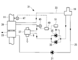
図1は、本実施形態にかかるボイラプラントの構成を示すブロック図である。図2は、図1の空気加熱装置の構成を示すブロック図である。
ボイラプラント1は、LNG船のタービン主機用として搭載され、LNGを主燃料として用い、かつ、重油焚きも可能とされているものである。
[第一実施形態]
この発明の第一実施形態にかかるボイラプラントについて、図1および図2を参照して説明する。
図1は、本実施形態にかかるボイラプラントの構成を示すブロック図である。図2は、図1の空気加熱装置の構成を示すブロック図である。
ボイラプラント1は、LNG船のタービン主機用として搭載され、LNGを主燃料として用い、かつ、重油焚きも可能とされているものである。
ボイラプラント1には、舶用ボイラ(ボイラ)3と、舶用ボイラ3で生成された蒸気を利用して回転されるタービン5と、舶用ボイラ3へ給水する給水系統7と、が備えられている。
タービン5は、蒸気を利用するものとして例示したものであり、これに限定されるものではない。また、図1では、タービン5を1個として図示しているが、これは、たとえば、高圧タービン、中圧タービン、低圧タービンおよび後進用タービンが用いられていてもよく、その構成は適宜とされる。
タービン5は、蒸気を利用するものとして例示したものであり、これに限定されるものではない。また、図1では、タービン5を1個として図示しているが、これは、たとえば、高圧タービン、中圧タービン、低圧タービンおよび後進用タービンが用いられていてもよく、その構成は適宜とされる。
舶用ボイラ5には、図示しないバーナの周囲に燃焼用空気を供給する空気ダクト9が備えられている。バーナは、空気ダクト9を介して導入される燃焼用空気を用いてLNGあるいは重油を燃焼させ、高温の燃焼ガスを生成する。
この燃焼ガスは下流の熱交換器のチューブ内を流れる水等の流体と熱交換して水等を加熱して蒸気とする。生成された蒸気は、たとえば、タービン5に供給され、タービン5に回転動力を与える。
こうして熱交換を終えた燃焼ガスは、燃焼排ガス流路11を通って排気される。
この燃焼ガスは下流の熱交換器のチューブ内を流れる水等の流体と熱交換して水等を加熱して蒸気とする。生成された蒸気は、たとえば、タービン5に供給され、タービン5に回転動力を与える。
こうして熱交換を終えた燃焼ガスは、燃焼排ガス流路11を通って排気される。
給水系統7には、タービン5の排気を冷却して復水する復水器13と、復水器13の復水を必要な圧力まで昇圧する復水昇圧ポンプ15と、タービン5からの抽気で給水を加熱する低圧給水加熱装置17と、タービン5から抽気された蒸気によって給水を直接加熱し、給水中の溶存ガスを物理的に分離除去する脱気器19と、給水の圧力を上げ下流側に押し込む給水ポンプ21と、燃焼排ガス流路11を通る燃焼排ガスによって給水を加熱させる排ガスエコノマイザ23と、が備えられている。
これら復水器13、復水昇圧ポンプ15、低圧給水加熱装置17、脱気器19、給水ポンプ21および排ガスエコノマイザ23は給水配管25により接続されている。
これら復水器13、復水昇圧ポンプ15、低圧給水加熱装置17、脱気器19、給水ポンプ21および排ガスエコノマイザ23は給水配管25により接続されている。
ボイラプラント1には、空気ダクト9を通って導入される燃焼用空気を加熱して昇温させる空気加熱装置31が備えられている。
空気加熱装置31には、脱気器19から分流され、空気ダクト9および燃焼排ガス流路11を通って脱気器19に戻るように循環した流路を形成する循環流路33と、脱気器19の温水を循環流路33に沿って循環させる温水循環ポンプ35と、空気ダクト9内を通る循環流路33に設けられ、空気ダクト9を通る燃焼用空気と熱交換を行う温水加熱式空気予熱器37と、燃焼排ガス流路11を通る循環流路33に設けられ、燃焼排ガス流路11を通る燃焼排ガスと熱交換を行う温水エコノマイザ(温水加熱器)39と、が備えられている。温水エコノマイザ39は、排ガスエコノマイザ23の下流側に備えられている。
空気加熱装置31には、脱気器19から分流され、空気ダクト9および燃焼排ガス流路11を通って脱気器19に戻るように循環した流路を形成する循環流路33と、脱気器19の温水を循環流路33に沿って循環させる温水循環ポンプ35と、空気ダクト9内を通る循環流路33に設けられ、空気ダクト9を通る燃焼用空気と熱交換を行う温水加熱式空気予熱器37と、燃焼排ガス流路11を通る循環流路33に設けられ、燃焼排ガス流路11を通る燃焼排ガスと熱交換を行う温水エコノマイザ(温水加熱器)39と、が備えられている。温水エコノマイザ39は、排ガスエコノマイザ23の下流側に備えられている。
温水循環ポンプ35は、2台が並列されており、1台は予備用として用いられる。
循環流路33には、温水循環ポンプ35と温水加熱式空気予熱器37との間から分岐し、脱気器19に接続される還流流路41が備えられている。
循環流路33と還流流路41との合流部には、三方調節弁43が備えられている。三方調節弁43は、温水循環ポンプ35からの温水を、温水加熱式空気予熱器37へ向かう温水と還流流路41へ向かう温水とを振り分けるとともに振り分ける割合を調節できる機能を有している。したがって、三方調節弁43を調節することによって、温水加熱式空気予熱器37へ向かう温水の流量を調節することができる。還流流路41へ振り分けられた余分な温水は脱気器19に戻されることになる。
循環流路33には、温水循環ポンプ35と温水加熱式空気予熱器37との間から分岐し、脱気器19に接続される還流流路41が備えられている。
循環流路33と還流流路41との合流部には、三方調節弁43が備えられている。三方調節弁43は、温水循環ポンプ35からの温水を、温水加熱式空気予熱器37へ向かう温水と還流流路41へ向かう温水とを振り分けるとともに振り分ける割合を調節できる機能を有している。したがって、三方調節弁43を調節することによって、温水加熱式空気予熱器37へ向かう温水の流量を調節することができる。還流流路41へ振り分けられた余分な温水は脱気器19に戻されることになる。
循環流路33の温水加熱式空気予熱器37の下流側には、内部を通過する温水の温度を検出する温水温度計45が備えられている。温水温度計45は、温水加熱式空気予熱器37を出た温水の温水温度を検出することになる。
燃焼排ガス流路11の温水エコノマイザ39の下流側には、内部を通過する燃焼排ガスの温度を検出する排ガス温度計47が備えられている。排ガス温度計47は、温水エコノマイザ(温水加熱器)39を出た燃焼排ガスの排ガス温度を検出することになる。
燃焼排ガス流路11の温水エコノマイザ39の下流側には、内部を通過する燃焼排ガスの温度を検出する排ガス温度計47が備えられている。排ガス温度計47は、温水エコノマイザ(温水加熱器)39を出た燃焼排ガスの排ガス温度を検出することになる。
空気加熱装置31には、制御部49が備えられている。制御部49は、温水温度が第一所定温度、たとえば、110℃を超えると三方調節弁43を調節して、温水加熱式空気予熱器37へ向かう温水の流量を減少させるように制御する。制御部49は、同時に、排ガス温度が第二所定温度、たとえば、120℃よりも低下すると、三方調節弁43を調節して、温水加熱式空気予熱器37へ向かう温水の流量を減少させるように制御する。
第一所定温度および第二所定温度は例示したものであり、第二所定温度が第一所定温度よりも高く設定されればよく、具体的な値は、状況に応じ適宜に設定される。
第一所定温度および第二所定温度は例示したものであり、第二所定温度が第一所定温度よりも高く設定されればよく、具体的な値は、状況に応じ適宜に設定される。
温水加熱式空気予熱器37は、温水(液体)と燃焼用空気(気体)との熱交換となるので、高い熱貫流率が得られるため、構造が簡単で、小型化することができる。
また、温水エコノマイザ39も、温水(液体)と燃焼排ガス(気体)との熱交換となるので、高い熱貫流率が得られるため、構造が簡単で、小型化することができる。
また、温水エコノマイザ39も、温水(液体)と燃焼排ガス(気体)との熱交換となるので、高い熱貫流率が得られるため、構造が簡単で、小型化することができる。
以下、このように構成された本実施形態にかかるボイラプラント1の動作について説明する。
タービン5の排気は、復水器13で冷却されて復水される。復水された水は、低圧給水加熱装置17で、タービン5から抽気された蒸気によって加熱されて、たとえば、約100℃の温水とされる。この温水が、脱気器19で、タービン5から抽気された蒸気によって加熱され、たとえば、約150℃の温水とされてボイラ3に向けて供給される。この温水は、さらに、排ガスエコノマイザ23によって燃焼排ガス流路11を通る燃焼排ガスによって加熱されて、ボイラ3に供給される。
タービン5の排気は、復水器13で冷却されて復水される。復水された水は、低圧給水加熱装置17で、タービン5から抽気された蒸気によって加熱されて、たとえば、約100℃の温水とされる。この温水が、脱気器19で、タービン5から抽気された蒸気によって加熱され、たとえば、約150℃の温水とされてボイラ3に向けて供給される。この温水は、さらに、排ガスエコノマイザ23によって燃焼排ガス流路11を通る燃焼排ガスによって加熱されて、ボイラ3に供給される。
このとき、温水循環ポンプ35が作動し、脱気器19内の温水を循環流路33に導入し、循環流路33に沿って循環させている。
この温水は、まず、温水加熱式空気予熱器37を通る際、空気ダクト9を通る燃焼用空気と熱交換される。温水は、導入される外気温の燃焼用空気を加熱し、ボイラ負荷が高いときには、たとえば、120℃まで昇温する。一方、温水は、燃焼用空気によって冷却され、たとえば、100℃まで減温される。
このように、燃焼用空気は、温水加熱式空気予熱器37によって昇温させられてボイラ3に供給されるので、燃料の燃焼効率を向上させることができる。
この温水は、まず、温水加熱式空気予熱器37を通る際、空気ダクト9を通る燃焼用空気と熱交換される。温水は、導入される外気温の燃焼用空気を加熱し、ボイラ負荷が高いときには、たとえば、120℃まで昇温する。一方、温水は、燃焼用空気によって冷却され、たとえば、100℃まで減温される。
このように、燃焼用空気は、温水加熱式空気予熱器37によって昇温させられてボイラ3に供給されるので、燃料の燃焼効率を向上させることができる。
一方、たとえば、ボイラ負荷が低下すると、燃焼用空気の供給量が減少するので、燃焼用空気が温水から吸収する熱量が低減される。吸収される熱量が低減すると、温水の冷却量が低減するので、温水温度計45が検出する温水温度が増加する。温水温度が、110℃を超えると、制御部49は、三方調節弁43を調節して、温水加熱式空気予熱器37へ向かう温水の流量を減少させ、余分な温水は還流流路41を通って脱気器19に戻される。温水の流量が低減されると、温水の熱量が低下するので、温水温度は下降する。
温水加熱式空気予熱器37を通って冷却された温水は、温水エコノマイザ39を通る際、燃焼排ガス流路11を通る燃焼排ガスと熱交換される。
ボイラ負荷が高いときには、温水エコノマイザ39を通る温水は、通過する、たとえば、150~160℃の燃焼排ガスを冷却し、たとえば、120℃まで減温する。一方、温水は、燃焼排ガスによって加熱され、たとえば、120℃まで昇温される。
このように、燃焼排ガスの廃熱は、温水エコノマイザ39および排ガスエコノマイザ23によって十分に回収することができるので、ボイラプラントの効率を向上させることができる。
ボイラ負荷が高いときには、温水エコノマイザ39を通る温水は、通過する、たとえば、150~160℃の燃焼排ガスを冷却し、たとえば、120℃まで減温する。一方、温水は、燃焼排ガスによって加熱され、たとえば、120℃まで昇温される。
このように、燃焼排ガスの廃熱は、温水エコノマイザ39および排ガスエコノマイザ23によって十分に回収することができるので、ボイラプラントの効率を向上させることができる。
一方、たとえば、ボイラ負荷が低下すると、燃焼排ガスの量が減少する。温水が燃焼排ガスから吸収する熱量はほとんど変わらないので、燃焼排ガスの温度が低減し、排ガス温度計47が検出する排ガス温度が低下する。排ガス温度が、120℃よりも低下すると、制御部49は、三方調節弁43を調節して、温水加熱式空気予熱器37へ向かう、すなわち、温水エコノマイザ39へ向かう温水の流量を減少させ、余分な温水は還流流路41を通って脱気器19に戻される。温水の流量が低減されると、温水の熱量が低下するので、燃焼排ガスから回収する熱量が減少し、排ガス温度は上昇する。
このように、制御部49は温水の流量を調節して、温水加熱式空気予熱器37を出る温水の温水温度が110℃よりも低くなるようにし、かつ、温水エコノマイザ39を出る燃焼排ガスの排ガス温度が120℃よりも高くなるようにしているので、温水エコノマイザ39に入る燃焼排ガスの温度は、温水の温度よりも少なくとも10℃以上に高くされている。したがって、温水エコノマイザ39における燃焼排ガスと温水との間には、確実に燃焼排ガスの方が高い温度差が存在するので、温水エコノマイザ39にて、温水は確実に燃焼排ガスの廃熱を回収することができる。
第二所定温度として120℃と設定しているので、温水エコノマイザ39の下流側での燃焼排ガスの排ガス温度は120℃以下になることはない。この120℃は、硫酸腐食の発生が抑えられる程度の温度であるので、たとえ、硫黄分の多い重油を燃焼したとしても硫酸腐食の発生を抑制することができる。
また、温水加熱式空気予熱器37を出る温水の温水温度が110℃よりも低くなるようにしているので、燃焼用空気に余分な熱量を与えて過度に温度を高くすることを抑制でき、省エネルギとできるし、燃焼用空気の温度を制御することができる。
また、温水加熱式空気予熱器37を出る温水の温水温度が110℃よりも低くなるようにしているので、燃焼用空気に余分な熱量を与えて過度に温度を高くすることを抑制でき、省エネルギとできるし、燃焼用空気の温度を制御することができる。
そして、温水加熱式空気予熱器37で供給した熱量を温水エコノマイザ39で回収した温水は脱気器19に戻される。
上述したように、脱気器19に戻される温水の温度は、脱気器19から導入した温水の温度よりも低くなるので、たとえば、脱気器19に供給される蒸気の熱量を少し増加させて、給水系統7での熱量バランスを設定することが好ましい。
これらの温度は、ボイラプラント1の条件によって変化するので、その条件に合うように適宜設定される。
上述したように、脱気器19に戻される温水の温度は、脱気器19から導入した温水の温度よりも低くなるので、たとえば、脱気器19に供給される蒸気の熱量を少し増加させて、給水系統7での熱量バランスを設定することが好ましい。
これらの温度は、ボイラプラント1の条件によって変化するので、その条件に合うように適宜設定される。
本実施形態では、循環流路33を循環する温水に、脱気器19の温水が用いられているので、温水は、脱気器19で脱気され余分な酸素が溶存していない。循環流路33は完全な閉ループとなっているので、途中で、余分な酸素が吸収されることがない。
したがって、この温水が給水系統7のいずれの部分に戻されても、たとえば、脱気器19以降の給水配管25に戻されたとしても、ボイラ3への給水に余分な酸素が含まれるのを防止することができる。
したがって、この温水が給水系統7のいずれの部分に戻されても、たとえば、脱気器19以降の給水配管25に戻されたとしても、ボイラ3への給水に余分な酸素が含まれるのを防止することができる。
[第二実施形態]
次に、本発明の第二実施形態にかかるボイラプラント1について、図3を用いて説明する。
本実施形態は、空気加熱装置31の構成が第一実施形態のものと異なるので、ここではこの異なる部分について主として説明し、前述した第一実施形態のものと同じ部分については重複した説明を省略する。
第一実施形態と同じ部材には同じ符号を付している。
図3は、本実施形態にかかるボイラの空気加熱装置を示すブロック図である。
次に、本発明の第二実施形態にかかるボイラプラント1について、図3を用いて説明する。
本実施形態は、空気加熱装置31の構成が第一実施形態のものと異なるので、ここではこの異なる部分について主として説明し、前述した第一実施形態のものと同じ部分については重複した説明を省略する。
第一実施形態と同じ部材には同じ符号を付している。
図3は、本実施形態にかかるボイラの空気加熱装置を示すブロック図である。
本実施形態の空気加熱装置31では、温水循環ポンプ35は、供給能力が調節可能とされている。
温水循環ポンプ35の供給能力を調節するインバータ51が備えられている。
制御部49は、インバータ51に温水供給量の制御信号を送り、インバータ51はその制御信号に沿って温水循環ポンプ35の温水供給量を制御するように構成されている。
温水循環ポンプ35の供給能力を調節するインバータ51が備えられている。
制御部49は、インバータ51に温水供給量の制御信号を送り、インバータ51はその制御信号に沿って温水循環ポンプ35の温水供給量を制御するように構成されている。
このように構成された本実施形態にかかるボイラプラント1の動作については、基本的に第一実施形態と同様であるので、ここでは重複した説明を省略する。
本実施形態では、温水の供給量を変更する場合、インバータ51が、温水循環ポンプ35の供給能力を調節して行われる。
したがって、温水循環ポンプ35は供給量に応じた能力で運転されるので、第一実施形態のように所定能力で運転され、過度な温水まで供給するものに比べて、温水循環ポンプ35の所要電力を削減することができる。
本実施形態では、温水の供給量を変更する場合、インバータ51が、温水循環ポンプ35の供給能力を調節して行われる。
したがって、温水循環ポンプ35は供給量に応じた能力で運転されるので、第一実施形態のように所定能力で運転され、過度な温水まで供給するものに比べて、温水循環ポンプ35の所要電力を削減することができる。
本発明は以上説明した各実施形態に限定されるものではなく、本発明の趣旨を逸脱しない範囲で種々の変形を行ってもよい。
1 ボイラプラント
3 ボイラ(舶用ボイラ)
7 給水系統
33 循環流路
37 温水加熱式空気予熱器
39 温水エコノマイザ
41 還流流路
43 三方調整弁
45 温水温度計
47 排ガス温度計
49 制御部
51 インバータ
3 ボイラ(舶用ボイラ)
7 給水系統
33 循環流路
37 温水加熱式空気予熱器
39 温水エコノマイザ
41 還流流路
43 三方調整弁
45 温水温度計
47 排ガス温度計
49 制御部
51 インバータ
Claims (4)
- ボイラへの給水系統の途中から温水が分流された後、該給水系統に合流する循環流路と、
該循環流路に設けられ、燃焼用空気と熱交換する温水加熱式空気予熱器と、
該温水加熱式空気予熱器の温水の流れ方向下流側に設けられ、前記ボイラの燃焼排ガスと熱交換する温水加熱器と、
前記循環流路を流れる前記温水の流量を調節する流量調節手段と、
前記温水加熱式空気予熱器を出た前記温水の温水温度を検出する温水温度検出器と、
前記温水加熱器を出た前記燃焼排ガスの排ガス温度を検出する排ガス温度検出器と、
前記温水温度が、第一所定温度よりも低くなるように、かつ、前記排ガス温度が、該第一所定温度よりも高く設定された第二所定温度よりも高くなるように、前記流量調節手段を調節して前記温水の流量を制御する制御部と、
が備えられているボイラプラント。 - 前記流量調節手段は、前記温水の一部を前記給水系統に戻すように構成された三方調整弁とされている請求項1に記載のボイラプラント。
- 前記流量調節手段は、供給能力が可変なポンプと、該ポンプの供給能力を調節するインバータと、で構成されている請求項1に記載のボイラプラント。
- ボイラへの給水系統の途中から温水が分流された後、該給水系統に合流する循環流路と、
該循環流路に設けられ、燃焼用空気と熱交換する温水加熱式空気予熱器と、
該温水加熱式空気予熱器の温水の流れ方向下流側に設けられ、前記ボイラの燃焼排ガスと熱交換する温水加熱器と、
前記循環流路を流れる前記温水の流量を調節する流量調節手段と、を備えるボイラプラントの運転方法であって、
前記温水加熱式空気予熱器を出た前記温水の温水温度および前記温水加熱器を出た前記燃焼排ガスの排ガス温度を検出し、
該温水温度が第一所定温度よりも低くなるように、かつ、前記排ガス温度が該第一所定温度よりも高く設定された第二所定温度よりも高くなるように、前記流量調節手段を制御して前記温水の流量を調節するボイラプラントの運転方法。
Applications Claiming Priority (2)
| Application Number | Priority Date | Filing Date | Title |
|---|---|---|---|
| JP2011040371A JP5832102B2 (ja) | 2011-02-25 | 2011-02-25 | ボイラプラントおよびその運転方法 |
| JP2011-040371 | 2011-02-25 |
Publications (1)
| Publication Number | Publication Date |
|---|---|
| WO2012114981A1 true WO2012114981A1 (ja) | 2012-08-30 |
Family
ID=46720762
Family Applications (1)
| Application Number | Title | Priority Date | Filing Date |
|---|---|---|---|
| PCT/JP2012/053716 Ceased WO2012114981A1 (ja) | 2011-02-25 | 2012-02-16 | ボイラプラントおよびその運転方法 |
Country Status (2)
| Country | Link |
|---|---|
| JP (1) | JP5832102B2 (ja) |
| WO (1) | WO2012114981A1 (ja) |
Cited By (8)
| Publication number | Priority date | Publication date | Assignee | Title |
|---|---|---|---|---|
| CN103115377A (zh) * | 2013-01-30 | 2013-05-22 | 中国科学院过程工程研究所 | 一种分控相变空气预热系统及空气预热方法 |
| CN103471084A (zh) * | 2013-09-11 | 2013-12-25 | 哈尔滨工业大学 | 低压热水烟气冷却系统及避免空气预热器低温腐蚀的方法 |
| CN106382651A (zh) * | 2016-10-22 | 2017-02-08 | 无锡翔龙环球科技股份有限公司 | 锅炉的余热回用及汽温控制系统 |
| CN108224465A (zh) * | 2018-01-23 | 2018-06-29 | 中国能源建设集团西北电力试验研究院有限公司 | 一种利用启动系统排水作为暖风器加热源的装置及方法 |
| EP3540309A1 (en) * | 2018-03-12 | 2019-09-18 | Bono Energia S.p.A. | System and corresponding high efficiency energy recovery method for industrial boilers or steam generators |
| CN114459016A (zh) * | 2022-02-25 | 2022-05-10 | 西安西热锅炉环保工程有限公司 | 一种低温省煤器联合暖风器全工况调节系统及方法 |
| CN115200004A (zh) * | 2022-07-27 | 2022-10-18 | 北京中电联节能技术有限公司 | 采用联合暖风器实现余热回收的系统及其使用方法 |
| US20230175685A1 (en) * | 2021-12-06 | 2023-06-08 | Maxi-Therme Inc. | Steam boiler system and method of circulating water and steam in a steam boiler system |
Families Citing this family (7)
| Publication number | Priority date | Publication date | Assignee | Title |
|---|---|---|---|---|
| KR101411513B1 (ko) | 2013-01-11 | 2014-06-24 | 삼성중공업 주식회사 | 이코노마이져를 이용한 공조시스템 |
| CN103438427B (zh) * | 2013-08-09 | 2015-06-24 | 天津诺能达能源科技有限公司 | 燃气锅炉余热回收系统及回收方法 |
| CN104976610A (zh) * | 2014-04-10 | 2015-10-14 | 冯伟忠 | 一种中温省煤器系统及其回收烟气余热的方法 |
| CN104807034A (zh) * | 2015-04-10 | 2015-07-29 | 广西方元电力股份有限公司来宾电厂 | 一种用于发电时提高空气预热器入口风温的装置 |
| CN204693472U (zh) * | 2015-04-22 | 2015-10-07 | 郝江平 | 一种空气预热和烟气余热利用系统 |
| CN105318313B (zh) * | 2015-04-29 | 2018-05-18 | 太原理工大学 | 一种基于scr脱硝装置的烟气余热利用系统 |
| JP6812770B2 (ja) * | 2016-12-08 | 2021-01-13 | 三浦工業株式会社 | ボイラシステム |
Citations (3)
| Publication number | Priority date | Publication date | Assignee | Title |
|---|---|---|---|---|
| JPS6245508U (ja) * | 1985-09-05 | 1987-03-19 | ||
| JPH08121703A (ja) * | 1994-10-24 | 1996-05-17 | Mitsubishi Heavy Ind Ltd | 排熱回収装置 |
| JP2010210230A (ja) * | 2009-03-10 | 2010-09-24 | Babcock & Wilcox Power Generation Group Inc | 一体型の、分離流れ型の水コイル式エアヒーター及びエコノマイザ(iwe) |
Family Cites Families (3)
| Publication number | Priority date | Publication date | Assignee | Title |
|---|---|---|---|---|
| JPS58123022A (ja) * | 1982-01-14 | 1983-07-22 | Mitsubishi Heavy Ind Ltd | バルブ廃液燃焼ボイラの排ガス熱回収システム |
| JPH10132207A (ja) * | 1996-10-28 | 1998-05-22 | Hitachi Zosen Corp | ボイラ設備 |
| JP2009192202A (ja) * | 2008-02-18 | 2009-08-27 | Mitsubishi Heavy Ind Ltd | 舶用ボイラの回転蓄熱式空気予熱器 |
-
2011
- 2011-02-25 JP JP2011040371A patent/JP5832102B2/ja not_active Expired - Fee Related
-
2012
- 2012-02-16 WO PCT/JP2012/053716 patent/WO2012114981A1/ja not_active Ceased
Patent Citations (3)
| Publication number | Priority date | Publication date | Assignee | Title |
|---|---|---|---|---|
| JPS6245508U (ja) * | 1985-09-05 | 1987-03-19 | ||
| JPH08121703A (ja) * | 1994-10-24 | 1996-05-17 | Mitsubishi Heavy Ind Ltd | 排熱回収装置 |
| JP2010210230A (ja) * | 2009-03-10 | 2010-09-24 | Babcock & Wilcox Power Generation Group Inc | 一体型の、分離流れ型の水コイル式エアヒーター及びエコノマイザ(iwe) |
Cited By (10)
| Publication number | Priority date | Publication date | Assignee | Title |
|---|---|---|---|---|
| CN103115377A (zh) * | 2013-01-30 | 2013-05-22 | 中国科学院过程工程研究所 | 一种分控相变空气预热系统及空气预热方法 |
| CN103115377B (zh) * | 2013-01-30 | 2015-08-19 | 中国科学院过程工程研究所 | 一种分控相变空气预热系统及空气预热方法 |
| CN103471084A (zh) * | 2013-09-11 | 2013-12-25 | 哈尔滨工业大学 | 低压热水烟气冷却系统及避免空气预热器低温腐蚀的方法 |
| CN106382651A (zh) * | 2016-10-22 | 2017-02-08 | 无锡翔龙环球科技股份有限公司 | 锅炉的余热回用及汽温控制系统 |
| CN108224465A (zh) * | 2018-01-23 | 2018-06-29 | 中国能源建设集团西北电力试验研究院有限公司 | 一种利用启动系统排水作为暖风器加热源的装置及方法 |
| EP3540309A1 (en) * | 2018-03-12 | 2019-09-18 | Bono Energia S.p.A. | System and corresponding high efficiency energy recovery method for industrial boilers or steam generators |
| US20230175685A1 (en) * | 2021-12-06 | 2023-06-08 | Maxi-Therme Inc. | Steam boiler system and method of circulating water and steam in a steam boiler system |
| US12130011B2 (en) * | 2021-12-06 | 2024-10-29 | Maxi-Therme Inc. | Steam boiler system and method of circulating water and steam in a steam boiler system |
| CN114459016A (zh) * | 2022-02-25 | 2022-05-10 | 西安西热锅炉环保工程有限公司 | 一种低温省煤器联合暖风器全工况调节系统及方法 |
| CN115200004A (zh) * | 2022-07-27 | 2022-10-18 | 北京中电联节能技术有限公司 | 采用联合暖风器实现余热回收的系统及其使用方法 |
Also Published As
| Publication number | Publication date |
|---|---|
| JP2012177512A (ja) | 2012-09-13 |
| JP5832102B2 (ja) | 2015-12-16 |
Similar Documents
| Publication | Publication Date | Title |
|---|---|---|
| JP5832102B2 (ja) | ボイラプラントおよびその運転方法 | |
| JP5050071B2 (ja) | ボイラ装置 | |
| US8186142B2 (en) | Systems and method for controlling stack temperature | |
| JP4554527B2 (ja) | 廃熱利用の省エネルギー設備 | |
| JP5228789B2 (ja) | 給湯装置 | |
| WO2020158941A1 (ja) | 蓄熱装置、発電プラントおよびファストカットバック時の運転制御方法 | |
| JP5832103B2 (ja) | ボイラプラント | |
| JP6053839B2 (ja) | ボイラ給水システム及びそれを備えたボイラ、並びにボイラ給水システムの制御方法 | |
| JP7403330B2 (ja) | 発電プラントおよび発電プラントにおける余剰エネルギ蓄熱方法 | |
| JP2012102711A (ja) | 減温器蒸気熱回収設備 | |
| JP7330690B2 (ja) | ボイラシステム及び発電プラント並びにボイラシステムの運転方法 | |
| JP4854422B2 (ja) | 貫流型排熱回収ボイラの制御方法 | |
| JP2009097735A (ja) | 給水加温システムおよび排熱回収ボイラ | |
| JP7086523B2 (ja) | 複合サイクル発電プラント、および、この複合サイクル発電プラントを動作させるための方法 | |
| JP6407612B2 (ja) | ガスパイプラインにおける減圧エネルギー回収装置 | |
| JP4283633B2 (ja) | 排熱回収器を有する二重効用形吸収式冷温水機 | |
| JP4415189B2 (ja) | 火力発電プラント | |
| JP5653861B2 (ja) | 温水器 | |
| JP6707058B2 (ja) | 廃熱ボイラ、廃熱回収システム、及び廃熱回収方法 | |
| CN110100078B (zh) | 具有燃气轮机进气系统的发电设备 | |
| JP5596216B1 (ja) | 廃棄物処理設備 | |
| JP2017223440A (ja) | ボイラプラント及びボイラプラント運転方法 | |
| JP4381242B2 (ja) | 舶用蒸気タービンプラント | |
| JP7308719B2 (ja) | 排熱回収システム | |
| JP2025139449A (ja) | 熱媒供給システム |
Legal Events
| Date | Code | Title | Description |
|---|---|---|---|
| 121 | Ep: the epo has been informed by wipo that ep was designated in this application |
Ref document number: 12749922 Country of ref document: EP Kind code of ref document: A1 |
|
| NENP | Non-entry into the national phase |
Ref country code: DE |
|
| 122 | Ep: pct application non-entry in european phase |
Ref document number: 12749922 Country of ref document: EP Kind code of ref document: A1 |