WO2012114850A1 - 塗布膜乾燥方法及び塗布膜乾燥装置 - Google Patents
塗布膜乾燥方法及び塗布膜乾燥装置 Download PDFInfo
- Publication number
- WO2012114850A1 WO2012114850A1 PCT/JP2012/052481 JP2012052481W WO2012114850A1 WO 2012114850 A1 WO2012114850 A1 WO 2012114850A1 JP 2012052481 W JP2012052481 W JP 2012052481W WO 2012114850 A1 WO2012114850 A1 WO 2012114850A1
- Authority
- WO
- WIPO (PCT)
- Prior art keywords
- substrate
- coating film
- heated gas
- stage
- drying
- Prior art date
- Legal status (The legal status is an assumption and is not a legal conclusion. Google has not performed a legal analysis and makes no representation as to the accuracy of the status listed.)
- Ceased
Links
Images





Classifications
-
- F—MECHANICAL ENGINEERING; LIGHTING; HEATING; WEAPONS; BLASTING
- F26—DRYING
- F26B—DRYING SOLID MATERIALS OR OBJECTS BY REMOVING LIQUID THEREFROM
- F26B21/00—Arrangements for supplying or controlling air or other gases for drying solid materials or objects
Definitions
- the present invention relates to a coating film drying method and a coating film drying apparatus for drying a film coated on the surface of a substrate, and in particular, a coating film drying method and a coating film drying that are suitably used for forming an alignment film such as a liquid crystal display device. Relates to the device.
- an alignment film for aligning liquid crystals is formed on the outermost surface of an array substrate or a counter substrate in which a predetermined layer is formed on a glass substrate.
- the alignment film is formed by, for example, applying a polyimide resin solution to the substrate surface, pre-baking (preliminary drying) to volatilize the solvent, and performing heat treatment (firing) to completely cure the polyimide resin to form a polyimide resin film. To do. Thereafter, an alignment film such as a rubbing process is applied to the surface of the polyimide film to form an alignment film.
- pre-baking and heat treatment steps are steps for drying the coating film (coating film drying step).
- a plurality of pins 102 are erected on a hot plate 101 and a polyimide resin solution is applied on the pins 102.
- the substrate 103 was placed horizontally, and the glass substrate 103 was heated by the hot plate 101 to temporarily dry the polyimide resin coating film.
- a coating film drying device used for drying a resist film is known as a coating film drying device that reduces coating unevenness of a coating film on the surface of a substrate (see Patent Document 1).
- the coating film drying apparatus of Patent Document 1 is a reduced-pressure drying apparatus that transports the substrate by placing it on a roller at the end while floating the center of the substrate with gas.
- the conventional method of placing a substrate on a pin and drying it has a problem that uneven pin marks or entire drying unevenness occurs in the polyimide resin film.
- the pin mark unevenness causes a thickness unevenness in the polyimide resin film in which the film thickness of the portion above the pin portion is different from the film thickness of the other portion not having the pin. This pin mark unevenness of the polyimide resin film is considered to occur due to the following reasons.
- the thermal conductivity of the pin 102 and air is different, a temperature difference occurs between the portion in contact with the pin 102 on the lower surface of the glass substrate 103 and the portion in contact with air. Then, a difference also occurs in the drying speed of the coating film.
- a difference in drying speed occurs between the pin portion of the polyimide resin coating film and the other portions, a difference in film thickness occurs in the polyimide resin film after drying, resulting in uneven pin marks on the polyimide resin coating film.
- the drying unevenness of the entire polyimide resin film is caused by the fact that there are a plurality of heat sources on the hot plate 101 and the temperature is not uniform but the temperature is not uniform.
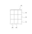
- the hot plate 101 includes nine heat sources 104 arranged in each of the nine divided areas. On the hot plate 101, since the nine heat sources 104 have slightly different characteristics, the temperature unevenness due to the heat sources 104 is generated, and it is considered that drying is not uniform.
- the substrate has a portion in contact with the stage and an end in contact with air or a roller during drying.
- the temperature change speed of the roller or stage is different from the temperature change speed of the space. For this reason, when the apparatus is depressurized, there is a difference between the temperature of the air portion and the temperature of the roller or stage, so that a temperature distribution occurs on the substrate. Further, when the stage end is cooled by the decompression space, there is a possibility that a temperature distribution is generated at the center of the stage and the end of the stage.
- the part in contact with other than the stage is outside the coating film area, but when the temperature distribution on the substrate, it affects the vapor pressure of the coating film solvent, Distribution occurs in the drying speed, which may cause unevenness.
- the substrate is attracted to the stage at the time of drying.
- the substrate floats without being attracted only to that portion. become. If it does so, temperature distribution will generate
- the problem to be solved by the present invention is that the dried coating film does not have uneven portions such as pin mark unevenness and drying unevenness, and can provide a uniform and uniform coating film with a uniform thickness. It is providing the drying apparatus and the coating film drying method.
- the coating film drying method of the present invention comprises: In the coating film drying method of heating and drying the substrate on which the coating film is formed on the surface, The substrate on which the coating film is formed is levitated in a substantially horizontal state on the upper part of the stage where the heated gas is jetted from the surface, the end surface of the substrate is held and the movement in the horizontal direction is restricted, and the coating film is formed.
- the gist of the invention is to dry the coating film by heating the substrate with the heated gas while the front and back surfaces of the substrate are not in contact with other members.
- the coating film drying apparatus of the present invention is A container that can be accommodated while the substrate is horizontally supported; A substrate support unit capable of horizontally supporting the substrate and extending and contracting vertically and used for receiving / dispensing the substrate; A substrate position fixing unit for restricting the horizontal position of the substrate in contact with the end face of the substrate; It has a stage formed so that heated gas can be ejected from the surface, and the substrate on which the coating film is formed can be levitated in a substantially horizontal state by ejecting heated gas from the lower surface of the substrate.
- the gist of the invention is to have a heated gas floating unit for drying the coating film on the surface of the substrate while the front and back surfaces are not in contact with other members.
- the coating film drying method of the present invention is a coating film drying method in which a substrate having a coating film formed on the surface is heated to dry, and the coating film is formed on the upper part of the stage where heated gas is jetted from the surface.
- the heated gas is floated in a substantially horizontal state, holds the end surface of the substrate and restricts horizontal movement, and the front and back surfaces of the substrate on which the coating film is formed are not in contact with other members.
- the coating film can be uniformly dried to form a uniform coating film free from pin mark unevenness and drying unevenness.
- the coating film drying apparatus of the present invention includes a container that can be accommodated in a state in which the substrate is horizontally supported, a substrate support unit that can horizontally support the substrate, and is used for receiving / dispensing the substrate by extending vertically.
- a substrate position fixing unit for regulating the horizontal position of the substrate in contact with the end surface of the substrate, and a stage formed so that the heated gas can be ejected from the surface, and the heated gas is supplied from the lower surface of the substrate
- the substrate on which the coating film is formed by spraying can be floated in a substantially horizontal state, and heating for drying the coating film on the surface of the substrate in a state where the front and back surfaces of the substrate are not in contact with other members.
- FIG. 1A and 1B are cross-sectional views showing a state in which a lift pin is raised
- FIG. 2B is a cross-sectional view showing a state in which the lift pin is lowered.
- FIG. 2B is a cross-sectional view showing a state in which the lift pin is lowered.
- FIG. 2B is a cross-sectional view showing a state in which the lift pin is lowered.
- FIG. 2B is a cross-sectional view showing a state in which the lift pin is lowered.
- FIG. 2B is a cross-sectional view showing a state in which the lift pin is lowered.
- (A)-(c) is process drawing which shows the Example of the coating film drying method of this invention. It is explanatory drawing of the coating film drying method of Example 3.
- FIG. It is explan
- FIG. 1 is an explanatory view schematically showing an outline of an example of a coating film drying apparatus.
- the coating film drying apparatus in FIG. 1 is a coating film drying apparatus used for drying an alignment film of a liquid crystal display device. That is, the coating film drying apparatus in FIG. 1 forms a coating film 3 by applying a polyimide resin solution in which a polyimide resin is dissolved in a solvent to the surface of a flat glass substrate 2 as an alignment film composition.
- 3 is an apparatus used for drying (pre-baking) the solvent of the polyimide resin solution 3.
- the coating film drying apparatus 1 has a space in which the glass substrate 2 can be horizontally placed, and a substrate support unit 20 for receiving / dispensing the glass substrate 2 in a container 10 formed so as to be hermetically sealed. 3), a substrate position fixing unit 30 for holding the glass substrate 2, and a heated air floating unit for injecting a heated gas from the stage 50 to float the glass substrate 2 to heat and dry the coating film 3.
- a substrate support unit 20 for receiving / dispensing the glass substrate 2 in a container 10 formed so as to be hermetically sealed. 3
- a substrate position fixing unit 30 for holding the glass substrate 2
- a heated air floating unit for injecting a heated gas from the stage 50 to float the glass substrate 2 to heat and dry the coating film 3.
- FIG. 2 is a plan view showing a glass substrate area in the coating film drying apparatus of FIG.
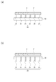
- FIG. 3 shows the substrate support unit of FIG. 1, (a) is a cross-sectional view showing a state where the elevating pins are raised, and (b) is a cross-sectional view showing a state where the elevating pins are lowered.
- the substrate support unit 20 includes a plurality of elevating pins 21 provided on the stage 50.
- the substrate support unit 20 has a plurality of elevating pins 21 arranged at predetermined intervals vertically and horizontally in a state where the stage 50 is viewed in plan.
- the substrate support unit 20 is formed by an elevating pin drive unit (not shown) such that the elevating pins 21 extend and contract above and below the stage 50.
- the drive unit of the substrate support unit 20 can move the entire plurality of lifting pins 21 together up and down.
- the substrate support unit 20 shown in FIG. 2 has lifting pins 21 provided in six rows in the vertical direction and 13 rows in the horizontal direction in FIG.
- the elevating pins 21 are distributed substantially uniformly over the entire substrate surface of the glass substrate 2, and the load of the glass substrate 2 is applied to each elevating pin 21 substantially evenly.
- the substrate support unit 20 raises the lift pins 21 when the glass substrate 2 is received / dispensed to / from the container 10 by robot conveyance.
- the tip portions of the elevating pins 21 come into contact with the lower surface of the glass substrate 2 to support the glass substrate 2 from below and hold it at a predetermined interval above the stage 50.
- the elevating pins 21 are lowered.
- the lower surface of the glass substrate 2 is in a non-contact state with the tips of the elevating pins 21.
- heated air is sprayed from the stage 50 onto the glass substrate 2 to float.
- the lower surface of the glass substrate 2 is supported by a robot transport device or the like.
- the substrate position fixing unit 30 is composed of a pair of substrate holding pins 31 and 32 provided in the vicinity of the diagonal corners of the glass substrate 2 as shown in FIG.
- the substrate holding pin 31 is provided so as to suppress the upper left corner of the glass substrate 2 in FIG. 2, and the substrate holding pin 32 is provided so as to suppress the lower right corner of the glass substrate in the plan view of FIG. ing.
- the glass substrate 2 is held by a pair of substrate holding pins 31 and 32 disposed at both diagonal ends of the substrate position fixing unit 30.
- the substrate holding pins 31 and 32 hold the two diagonal directions of the glass substrate 2 to restrict the horizontal position of the glass substrate 2 to a predetermined position.
- the substrate holding pins 31 and 32 also have a function as mechanical alignment that determines the fixing position of the glass substrate 2 in the horizontal direction.
- the substrate holding pin 31 is composed of a pair of pin members 31 a and 31 b provided on two adjacent sides of one corner of the glass substrate 2.
- the substrate holding pin 32 is composed of a pair of pin members 32 a and 32 b provided at diagonal positions of the substrate holding pin 31 of the glass substrate 2.
- the pin members 31a, 31b, 32a, and 32b are in contact with only the end surface of the glass substrate 2 to suppress the horizontal movement of the glass substrate 2.
- the pin members 31a, 31b, 32a, and 32b are formed so as to be movable in any horizontal direction so that they can be brought into contact with or not in contact with the end face of the glass substrate 2 by a drive mechanism (not shown). ing.
- the pin members 31a, 31b, 32a, and 32b are in contact with the end surfaces of two adjacent sides of the glass substrate 2, and the glass substrate 2 is pressed by the pin members 31a, 31b, 32a, and 32b, and the glass substrate 2 Is held at a predetermined position, and the position in the horizontal direction is restricted.
- the set of pin members 31a and 31b or the set of pin members 32a and 32b may be driven so as to be in contact / non-contact with the glass substrate 2 separately.
- the glass substrate 2 may be integrally driven to be in contact / non-contact.
- the pin members 31 a, 31 b, 32 a, and 32 b of the substrate holding pins 31 and 32 are formed in a shape that contacts only the end surface of the glass substrate 2 and does not contact the front and back surfaces of the glass substrate 2.
- the shape of the pin member is better as the contact surface with the glass substrate is smaller in order to minimize the influence on the temperature distribution of the glass substrate 2.
- the shape of the pin member having a small contact area with the glass substrate is a columnar shape, a spherical shape, or the like such that the cross section of the contact portion is circular.
- the glass substrate 2 is entirely levitated by a heated air levitating unit described later. Therefore, the substrate position fixing unit 30 does not need to support the vertical direction of the glass substrate 2.
- heated air is jetted from the stage 41 of the heated gas levitation unit 40 to the glass substrate 2 in a state where the glass substrate 2 is pinned up by the lift pins 21 of the substrate support unit 20, the glass substrate 2 floats above the stage.
- the substrate restraining pin 31 of the substrate position fixing unit 30 is brought into contact with the end surface of the glass substrate 2 to restrain the glass substrate 2 and restrict the horizontal position of the glass substrate 2. If the elevating pins 21 of the substrate support unit are lowered in this state, the glass substrate 2 can be dried in a state where it is not in contact with the elevating pins 21.
- FIG. 4 is a plan view showing another example of the substrate position fixing unit.
- the substrate position fixing unit 30 shown in FIG. 4 is provided with substrate holding pins 33 and 34 in the vicinity of two other corners in addition to the substrate holding pins 31 and 32, and the four corners of the glass substrate 2 are formed. It is comprised so that it may hold
- the board holding pin 33 is composed of two pins 33a and 33b.
- the board holding pin 34 includes two pins 34a and 34b.
- the heated air levitation unit includes a stage 50 for injecting heated air upward to float the upper glass substrate 2, and an air supply unit for supplying heated air to the stage 50. 60, an exhaust unit 70 for exhausting heated air through the stage 50, and an air heating device 80 for feeding air heated to a predetermined temperature to the air supply unit 60.
- a stage 50 for injecting heated air upward to float the upper glass substrate 2
- an air supply unit for supplying heated air to the stage 50. 60
- an exhaust unit 70 for exhausting heated air through the stage 50
- an air heating device 80 for feeding air heated to a predetermined temperature to the air supply unit 60.
- the stage 50 is formed as a plate-like body having a size substantially the same as the size of the glass substrate 2, and a large number of fine discharge holes 51 and exhaust holes 52 are provided on the surface.
- the discharge holes 51 and the exhaust ports 52 are arranged on the entire surface of the stage 50 so as to have a uniform density.
- the discharge hole 51 is piped to the air supply unit 60 and is formed so that heated air can be jetted upward. Further, the exhaust hole 52 is piped to the exhaust unit 70 so that the air from the discharge hole 51 can be discharged to the outside of the container 10.
- the stage 50 is configured to uniformly inject heated air for levitation onto the upper glass substrate 2.
- the air supply unit 60 is formed so that the amount of heated air supplied can be adjusted.
- the exhaust unit 70 is formed so as to be able to adjust the amount of air discharged in the chamber of the container 10.
- the air heating device 80 is configured to be able to heat air to a predetermined temperature and send heated air to the air supply unit.
- the air heating device 80 is connected to the exhaust unit 70 and is formed so as to be reheatable by supplying air discharged outside the container 10.
- the air supply unit 60 may be connected to the exhaust hole of the stage 50. Heated air from the air supply unit 60 can be switched between injection from the discharge hole 51 and injection from the exhaust hole 52 of the stage 50. The injection from the discharge hole 51 and the injection from the exhaust hole 52 can be performed alternately.
- the exhaust unit 70 may be connected to the discharge hole 51 of the stage 50. When exhausting the inside of the container using the exhaust unit 70, the exhaust from the exhaust hole 52 of the stage 50 and the exhaust from the discharge hole 51 can be switched. The exhaust from the exhaust hole 52 and the exhaust from the discharge hole 51 can be performed alternately. The relationship between the discharge hole 51 and the exhaust hole 52 is such that when heated air is injected from one hole, the air is exhausted from the other hole.
- the heated air levitation unit is equipped with a drive device that allows the stage 50 to swing in the horizontal direction.
- the oscillating device reciprocates the stage 50 by a predetermined distance in the horizontal direction, and is formed so that the relative position with respect to the glass substrate 2 changes.
- the substrate position fixing unit 30 may be configured to be drivable so that the substrate position fixing unit 30 holding the glass substrate 2 swings in the horizontal direction.
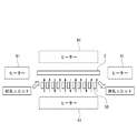
- FIG. 5 is an explanatory view showing the outline of another example of the coating film drying apparatus.
- the coating film drying apparatus may be configured to heat the glass substrate 2 by arranging a plurality of heat sources such as a heater 91 around the stage 50 as shown in FIG.
- the glass substrate 2 can be dried using the heated air and the heater 91 in combination.
- the heat source 91 may be arranged with a temperature distribution in advance.
- a plurality of heat sources 91 can be switched and used. Depending on drying unevenness, the heat source can be adjusted so as to have an optimum temperature distribution.
- the outside of the substrate is cooled more than the central portion.
- the temperature can be corrected by heating only the periphery of the substrate with a heat source such as a heater.
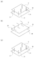
- Example 1 is a coating film drying method using the coating film drying apparatus shown in FIGS. 6A to 6C are process diagrams showing an embodiment of the coating film drying method of the present invention.
- a glass substrate 2 having a surface coated with an alignment film composition is applied to a container 10 (not shown) of the coating film drying apparatus 1 by a robot transport device or the like. Carry in.
- the lift pins 21 of the stage 50 are in a raised state, and the lower surface of the glass substrate 2 is supported by the lift pins 21.
- the coating film is an alignment film using a polyimide resin solution
- the polyimide resin solution is transferred to a resin relief using an anilox roller, and is printed on the glass substrate 2 and transferred. Etc. are used.
- the coating film of the polyimide resin solution is usually formed to about 10 to 100 nm.
- the coating film on the glass substrate 2 is temporarily dried in a drying process to volatilize the solution.
- the end portions of the glass substrate 2 are held by the substrate holding pins 31 and 32 of the substrate position fixing unit 30 to restrict the horizontal position of the glass substrate.
- heated air is supplied from the air supply unit 60 to the discharge holes 51 of the stage 50, and the heated air is ejected from the discharge holes. Also, air is discharged from the exhaust hole of the stage by the exhaust unit. In this case, the air supply amount and the exhaust amount are adjusted as appropriate so that the glass substrate 2 floats from the stage.
- the glass substrate 2 When the raising / lowering pins 21 of the substrate support unit are lowered, the glass substrate 2 is floated by the heated air sprayed from the stage. Since the end portion of the glass substrate 2 is held by the substrate holding pin, the position in the horizontal direction is regulated and held at a predetermined position. Moreover, since the glass substrate 2 is floating above the stage by heated air, the front and back surfaces of the glass substrate 2 are not in contact with other members.
- the polyimide substrate applied to the surface of the glass substrate 2 is dried for a predetermined time in a state where the glass substrate 2 is floated by heated air.
- the alignment film which is the coating film 3 is dried.
- the lower surface of the glass substrate 2 is not in contact with the lift pins 21.
- the front and back surfaces of the glass substrate 2 are not in contact with other members.
- pin mark unevenness due to the lift pins does not occur.
- the temperature of the portion where the glass substrate 2 is in contact with another member is changed.
- the portion becomes uneven in drying.
- the pin members 31a, 31b, 32a, and 32b are only in contact with the end surface of the glass substrate 2 with a minimum area.
- substrate position fixing unit 30 can make small the change of the temperature by the contact with the glass substrate 2, it can suppress a drying nonuniformity to the minimum.
- the heated air is supplied to the inside of the container 2 in a state where the temperature is adjusted to a constant temperature by the air heating device 80.
- the heated air injected from the stage 50 has no temperature variation.
- the heated air heated to a certain temperature uniformly heats the entire glass substrate 2. Therefore, as in the conventional case, when a plurality of heat sources are arranged and heated and dried, the temperature differs depending on the heat source, and a portion where the temperature is partially different in the glass substrate 2 occurs, resulting in uneven drying. Can be prevented.
- the stage 50 is provided with fine discharge holes 51 and exhaust holes 52 with a uniform density throughout. Heated air for levitation is uniformly jetted onto the glass substrate 2. Therefore, if the amount of exhaust from the exhaust hole by the exhaust unit is adjusted, the distance between the surface of the stage 50 and the lower surface of the glass substrate 2 can be easily kept constant. Further, since the discharge holes and the exhaust holes of the stage 50 are arranged at a uniform density, the heated air is uniformly sprayed onto the glass substrate 2 and is heated so that the temperature of the glass substrate becomes uniform. be able to.
- the glass substrate 2 When heating is performed for a predetermined time in the mode shown in FIG. 6B and drying is completed, the glass substrate 2 is supported from below by raising the elevating pins 21 from the stage 50 as shown in FIG. It will be in the state. The injection of the heated air from the stage 50 is finished, the substrate holding pins 31 and 32 of the substrate position fixing unit 30 are moved, and the horizontal holding of the glass substrate 2 is released. The glass substrate 2 is carried out of the coating film drying apparatus 1 by a robot transfer device or the like.
- the coating film drying method of Example 2 uses the coating film drying apparatus of the aspect shown in FIG.
- a heat source such as a heater 91 is arranged around the stage 50.
- the heater 91 can heat the glass substrate 2 with the radiant heat of each heater from the vertical direction of the glass substrate 2, the horizontal direction of the glass substrate 2, and the horizontal direction of the glass substrate 2.
- Each heater 91 can individually adjust the heating temperature and the like.
- the difference of the coating film drying method of Example 2 from Example 1 is that the coating film on the glass substrate is heated by using heat air and heat from a heat source such as the heater 91 at the time of drying.
- a heat source such as the heater 91 at the time of drying.
- Other processing conditions are the same as those in the first embodiment.
- the method of heating using the heat of the heat source of Example 2 together with heated air has the following advantages. For example, in the container 10, heated air supply and exhaust may pass outside the glass substrate 2. In this case, the peripheral side of the glass substrate 2 is cooled more than the central side. Therefore, by heating using the heater 91 disposed around the glass substrate 2, the low temperature around the glass substrate 2 is corrected, and the temperature with the central portion of the glass substrate 2 is made uniform to perform drying. Can do.
- the dry temperature distribution of the glass substrate 2 is made more uniform by correcting the temperature distribution in the container 10 by using the heat of the heat source such as the heater 91 together with the heated air.
- the coating film without any unevenness can be dried.
- FIG. 7 is an explanatory diagram of the coating film drying method of Example 3.
- the third embodiment is different from the first embodiment in that heated air injected from the stage 50 is injected using a switching mechanism of the supply / exhaust system. Other processing conditions are the same as those in the first embodiment.
- the heated air jetted from the discharge holes is jetted from the exhaust holes, and the air exhausted from the exhaust holes is exhausted from the air supply holes to be jetted.
- the spray holes are switched and the coating film of the glass substrate 2 is heated and dried.
- Switching between supply and exhaust of heated air may be performed only once during this drying process, but may be performed a plurality of times. For example, switching between air supply and exhaust is performed at regular intervals, and heating air is ejected from the discharge holes and exhausted from the exhaust holes, and heated air is ejected from the exhaust holes and exhausted from the discharge holes at regular intervals. Alternatively, drying may be performed alternately.
- the coating film drying method of Example 3 has the following advantages.
- the temperature differs between the upper portion of the discharge hole 51 and the upper portion of the exhaust hole 52 of the glass substrate 2 depending on the gap (interval) between the stage 50 and the glass substrate, the ratio of the air supply amount and the exhaust amount, and the like. Distribution may occur.
- the temperature of the upper part of the exhaust hole 52 is lower than that of the upper part of the discharge hole 51 because air from which heat has been removed is exhausted.
- the temperature can be made uniform by alternately injecting heated air from the discharge holes and the exhaust holes. For example, a specific portion is cooled to cause a temperature drop and a temperature distribution is generated because the specific portion is maintained at a low temperature for a certain period of time.
- the temperature can be made uniform and drying unevenness can be prevented by switching the injection position of the heated air so as not to give the cooling time.
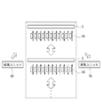
- FIG. 8 is an explanatory diagram of the coating film drying method of Example 4.
- the relative positional relationship between the glass substrate 2 on which the coating film 3 is formed and the stage 50 is set such that the stage 50 is horizontally moved from the state [A].
- the state is moved from the left to the right in the direction diagram to the state [B].
- the relative positional relationship between the glass substrate 2 and the stage 50 is changed from the state [B] to the state [A] by moving the stage 50 from the right to the left in the horizontal view.
- This reciprocation in the state of [A]-[B] is repeatedly performed to swing the so-called stage 50 in the horizontal direction.
- the coating film drying method of Example 4 is different from Example 1 in that drying is performed by swinging the glass substrate 2 or the stage 50.
- Other processing conditions are the same as those in the first embodiment.
- the stage 50 may be swung continuously during the coating film drying process, or the stage 50 may be swung intermittently while holding the stage in the state [A] and the state [B] for a certain period of time. Or either. Further, since the swinging is performed by changing the relative positional relationship between the stage 50 and the glass substrate 2 in the horizontal direction, the glass substrate 2 may be moved. When the glass substrate 2 is swung, the substrate position fixing unit 30 is swung. In this case, the substrate position fixing unit 30 moves independently from the stage 50.
- Example 4 the relative position in the horizontal direction of the glass substrate 2 and the stage 50 changes during drying of the coating film.
- a coating film drying method of Example 4 has the following advantages.
- the temperature differs between the upper portion of the discharge hole 51 and the upper portion of the exhaust hole 52 of the glass substrate 2 depending on the gap (interval) between the stage 50 and the glass substrate, the ratio of the air supply amount and the exhaust amount, and the like. Distribution may occur.
- the relative position between the two is fixed, the temperature distribution according to the position in the horizontal direction is fixed.
- the temperature distribution can be dispersed, the temperature can be made uniform, and drying unevenness can be suppressed.
- this invention is not limited to the said Example, It can implement in a various aspect.
- the above embodiment has shown an example of a method for drying an alignment film of a liquid crystal display device and an example of a drying device, but the present invention can be used if the coating film applied to the substrate surface is heated and dried. Is possible.
- the present invention can also be applied to, for example, drying a photoresist film as another coating film.
Landscapes
- Engineering & Computer Science (AREA)
- Mechanical Engineering (AREA)
- General Engineering & Computer Science (AREA)
- Drying Of Solid Materials (AREA)
Abstract
本発明は、乾燥した塗布膜にピン跡ムラや乾燥ムラ等の不均一な部分が発生せず、厚みが均一でムラのない乾燥した塗布膜を得ることを可能としたものである。本発明の塗布膜乾燥装置及び塗布膜乾燥方法は、表面に塗布膜(3)が形成された基板(2)を加熱して乾燥する際、表面から加熱気体を噴射しているステージ(50)の上部に、前記塗布膜(3)が形成された基板(2)を略水平状態に浮上させ、前記基板(2)の端面を保持し水平方向の移動を規制し、前記塗布膜(3)が形成された基板(2)の表裏両面が他の部材と非接触の状態で、前記加熱気体により前記基板を加熱して塗布膜(3)を乾燥させた。
Description
本発明は、基板の表面に塗布した膜を乾燥する塗布膜乾燥方法及び塗布膜乾燥装置に関し、特に液晶表示装置等の配向膜を形成するのに好適に用いられる塗布膜乾燥方法及び塗布膜乾燥装置に関する。
例えば液晶表示装置の製造において、ガラス基板に所定の層が形成されたアレイ基板や対向基板の最表面に液晶を配向させるための配向膜が形成される。配向膜は、例えばポリイミド樹脂の溶液を基板表面に塗布し、プリベーク(仮乾燥)を行って溶媒を揮発させ、熱処理(焼成)を行ってポリイミド樹脂を完全に硬化させて、ポリイミド樹脂膜を形成する。その後、ポリイミド膜の表面にラビング処理等の配向処理を施すことで配向膜が形成される。上記のプリベーク及び熱処理の工程が、塗布膜を乾燥する工程(塗布膜乾燥工程)である。
従来、配向膜の形成の際の塗布膜乾燥工程では、図9に示すように、ホットプレート101の上に複数のピン102を立て、該ピン102の上にポリイミド樹脂の溶液が塗布されたガラス基板103を水平に載置し、上記ホットプレート101によりガラス基板103を加熱してポリイミド樹脂塗布膜の仮乾燥を行っていた。
液晶表示装置の製造において、基板の表面の塗布膜の塗布ムラを低減させた塗布膜乾燥装置として、例えば、レジスト膜の乾燥に用いられる塗布膜乾燥装置が公知である(特許文献1参照)。特許文献1の塗布膜乾燥装置は、ガスにより基板中央部を浮上させながら、端部のコロに載せて搬送する減圧乾燥装置である。
しかし、上記従来のピンの上に基板を載せ乾燥する方法では、ポリイミド樹脂膜に、ピン跡ムラや、全体の乾燥ムラが発生するという問題があった。ピン跡ムラとは、ポリイミド樹脂膜に、上記ピンの部分の上の部分の膜厚と、それ以外のピンのない部分の上の膜厚が異なる厚みムラが発生する。このポリイミド樹脂膜のピン跡ムラは、下記の原因で発生するものと考えられる。
塗布膜乾燥工程では、ピン102と空気の熱伝導率が異なるため、ガラス基板103の下面においてピン102と接している部分と、空気と接している部分とでは、温度差が生じる。すると、塗布膜の乾燥速度にも差が生じる。ポリイミド樹脂塗布膜のピンの部分とそれ以外の部分で乾燥速度に差が出ると、乾燥後のポリイミド樹脂膜に膜厚差が生じて、ポリイミド樹脂塗布膜のピン跡ムラとなる。
また、ポリイミド樹脂膜全体の乾燥ムラは、ホットプレート101に熱源が複数個あり、全体の温度が均一にならずに、温度が不均一になることに起因しているものと考えられる。例えば、図10に示すように、上記ホットプレート101は、9分割されている各領域に9個の熱源104が配置されて構成されている。ホットプレート101の上では、9個の熱源104は各熱源の特性が微妙に異なることから、熱源104による温度ムラが発生して、乾燥が不均一になるものと考えられる。
また上記特許文献1に記載されている減圧乾燥装置は、ピンがないので、ピン跡ムラは発生しない。またエア浮上は基板搬送時のみだが、エアの噴出を微細孔からの噴出により均一化して、温度ムラを発生させないようにしている。
しかし上記特許文献1に記載の減圧乾燥装置は、乾燥時、基板にはステージに接している部分と、空気またはコロに接している端部とがある。コロやステージの温度変化速度は、空間の温度変化速度とは異なる。そのため、装置を減圧した際、空気部分の温度とコロやステージの温度には差が生じるので、基板には温度分布が発生することになる。また、ステージ端が減圧空間により冷却されると、ステージの中央部とステージの端部に温度分布が発生する可能性がある。
上記減圧乾燥装置で基板の塗布膜を乾燥する場合、ステージ以外と接する部分は、塗布膜エリアよりも外側となるが、基板に温度分布が出ると、塗布膜溶媒の蒸気圧に影響を与え、乾燥速度に分布が生じることになり、ムラ発生の原因となる可能性がある。
また上記減圧乾燥装置では、乾燥時、基板をステージに吸着するため、例えばステージ上に異物が載ったり、基板の裏面に異物が付着した場合、その部分のみ吸着されずに基板が浮いてしまうことになる。そうすると塗布膜エリアに温度分布が発生することになり、乾燥速度に差が生じて、ムラ発生の原因となるという問題があった。
本発明が解決しようとする課題は、乾燥した塗布膜にピン跡ムラや乾燥ムラ等の不均一な部分が発生せず、厚みが均一でムラのない塗布膜を得ることが可能である塗布膜乾燥装置及び塗布膜乾燥方法を提供することにある。
本発明の塗布膜乾燥方法は、
表面に塗布膜が形成された基板を加熱して乾燥する塗布膜乾燥方法において、
表面から加熱気体を噴射しているステージの上部に、前記塗布膜が形成された基板を略水平状態に浮上させ、前記基板の端面を保持し水平方向の移動を規制し、前記塗布膜が形成された基板の表裏両面が他の部材と非接触の状態で、前記加熱気体により前記基板を加熱して塗布膜を乾燥させることを要旨とするものである。
表面に塗布膜が形成された基板を加熱して乾燥する塗布膜乾燥方法において、
表面から加熱気体を噴射しているステージの上部に、前記塗布膜が形成された基板を略水平状態に浮上させ、前記基板の端面を保持し水平方向の移動を規制し、前記塗布膜が形成された基板の表裏両面が他の部材と非接触の状態で、前記加熱気体により前記基板を加熱して塗布膜を乾燥させることを要旨とするものである。
本発明の塗布膜乾燥装置は、
基板を水平に支持した状態で収容可能な容器と、
前記基板を水平に支持可能であり上下に伸縮して該基板の受け入れ/払い出しに用いられる基板支持ユニットと、
前記基板の端面と接触して基板の水平方向の位置を規制するための基板位置固定ユニットと、
表面から加熱気体を噴射可能に形成されたステージを有し、前記基板の下面から加熱気体を噴射して塗布膜が形成された基板を略水平状態に浮上させることが可能であり、前記基板の表裏面が他の部材と非接触の状態で該基板表面の塗布膜を乾燥するための加熱気体浮上ユニットを有することをを要旨とするものである。
基板を水平に支持した状態で収容可能な容器と、
前記基板を水平に支持可能であり上下に伸縮して該基板の受け入れ/払い出しに用いられる基板支持ユニットと、
前記基板の端面と接触して基板の水平方向の位置を規制するための基板位置固定ユニットと、
表面から加熱気体を噴射可能に形成されたステージを有し、前記基板の下面から加熱気体を噴射して塗布膜が形成された基板を略水平状態に浮上させることが可能であり、前記基板の表裏面が他の部材と非接触の状態で該基板表面の塗布膜を乾燥するための加熱気体浮上ユニットを有することをを要旨とするものである。
本発明の塗布膜乾燥方法は、表面に塗布膜が形成された基板を加熱して乾燥する塗布膜乾燥方法において、表面から加熱気体を噴射しているステージの上部に、前記塗布膜が形成された基板を略水平状態に浮上させ、前記基板の端面を保持し水平方向の移動を規制し、前記塗布膜が形成された基板の表裏両面が他の部材と非接触の状態で、前記加熱気体により前記基板を加熱して塗布膜を乾燥させることにより、塗布膜を均一に乾燥して、ピン跡ムラや、乾燥ムラのない均一な塗布膜を形成することが可能である。
本発明の塗布膜乾燥装置は、基板を水平に支持した状態で収容可能な容器と、前記基板を水平に支持可能であり上下に伸縮して該基板の受け入れ/払い出しに用いられる基板支持ユニットと、前記基板の端面と接触して基板の水平方向の位置を規制するための基板位置固定ユニットと、表面から加熱気体を噴射可能に形成されたステージを有し、前記基板の下面から加熱気体を噴射して塗布膜が形成された基板を略水平状態に浮上させることが可能であり、前記基板の表裏面が他の部材と非接触の状態で該基板表面の塗布膜を乾燥するための加熱気体浮上ユニットを有することにより、塗布膜を均一に乾燥して厚みムラのない均一な塗布膜を形成することが可能である。
以下、本発明の実施例について図面を参照して詳細に説明する。図1は塗布膜乾燥装置の一例の概略を模式的に示した説明図である。図1の塗布膜乾燥装置は、液晶表示装置の配向膜の乾燥に用いられる塗布膜乾燥装置である。すなわち、図1の塗布膜乾燥装置は、ポリイミド樹脂が溶媒に溶解されたポリイミド樹脂溶液を配向膜組成物として平板状のガラス基板2の表面に塗布して塗布膜3を形成した後、塗布膜3のポリイミド樹脂溶液の溶媒を乾燥(プリベーク)するために用いる装置である。
塗布膜乾燥装置1は、ガラス基板2を水平に載置可能な空間を有し、内部を密閉可能に形成された容器10内に、ガラス基板2の受け入れ/払い出し用の基板支持ユニット20(図3参照)と、ガラス基板2を保持する基板位置固定ユニット30と、ステージ50から加熱気体を噴射してガラス基板2を浮上させて塗布膜3を加熱して乾燥するための加熱エア浮上ユニットとを有する。以下、各ユニットの構成について説明する。
図2は図1の塗布膜乾燥装置におけるガラス基板エリアを示す平面図である。図3は、図1の基板支持ユニットを示し、(a)は昇降ピンを上昇させた状態を示す断面図であり、(b)は昇降ピンを下降させた状態を示す断面図である。図2及び図3に示すように、基板支持ユニット20は、ステージ50に設けた複数の昇降ピン21から構成されている。図2に示すように、基板支持ユニット20はステージ50を平面視した状態で、複数の昇降ピン21が、縦横に所定の間隔で配置されている。また基板支持ユニット20は、昇降ピン駆動ユニット(図示せず)により、昇降ピン21がステージ50の上方を上下に伸縮するように形成されている。基板支持ユニット20の駆動ユニットは、複数の昇降ピン21全体を一緒に上下に移動させることができる。
図2に示す基板支持ユニット20は、昇降ピン21が図2中縦方向に6列、横方向に13列設けられ、合計78個の昇降ピン21を有している。昇降ピン21は、ガラス基板2の基板面に対し全体に略均一に分散配置されていて、各昇降ピン21にガラス基板2の荷重が略均等に加わるようになっている。
図3(a)に示すように、基板支持ユニット20は、ロボット搬送によりガラス基板2を容器10に受け入れ/払い出しする際に、昇降ピン21を上昇させる。昇降ピン21が上昇した状態では、昇降ピン21の先端部分がガラス基板2の下面と接触して、ガラス基板2を下から支持して、ステージ50上方の所定の間隔の位置に保持する。図3(b)に示すように、ガラス基板2を加熱して塗布膜を乾燥する際には、昇降ピン21を下降させる。図3(b)に示すように、昇降ピン21が下降すると、ガラス基板2の下面は昇降ピン21の先端は非接触状態となる。この状態で乾燥を行う場合は、ガラス基板2にステージ50から加熱空気を噴射して浮上させる。またガラス基板2を容器10の外部に搬送する場合は、ガラス基板2の下面がロボット搬送装置等により支持される。
基板位置固定ユニット30は、図2に示すように、ガラス基板2の対角方向の角の近傍に設けられた一対の基板抑えピン31、32から構成されている。基板抑えピン31は、図2中でガラス基板2の左上の角を抑えるように設けられ、基板抑えピン32は、図2の平面図中でガラス基板の右下の角を抑えるように設けられている。
ガラス基板2は、基板位置固定ユニット30の対角方向両端に配置された一対の基板抑えピン31、32により保持されている。基板抑えピン31、32は、ガラス基板2の対角方向2箇所を保持することで、ガラス基板2の水平方向の位置を所定の位置に規制している。基板抑えピン31、32は、ガラス基板2の水平方向の固定位置を決めるメカアライメントとしての機能も有している。
基板抑えピン31は、ガラス基板2の一つの角の隣接する2辺に設けられた一組のピン部材31a、31bから構成されている。基板抑えピン32は、ガラス基板2の基板抑えピン31の対角位置に設けた、一組のピン部材32a、32bから構成されている。ピン部材31a、31b、32a、32bは、ガラス基板2の端面のみと接触してガラス基板2の水平方向の移動を抑制している。
ピン部材31a、31b、32a、32bは、特に図示しない駆動機構により、ガラス基板2の端面と接触させたり非接触としたりすることができるように、水平方向の任意の方向に移動可能に形成されている。ピン部材31a、31b、32a、32bが、ガラス基板2の隣接する2辺の端面に接触した状態になって、ガラス基板2がピン部材31a、31b、32a、32bにより押圧されて、ガラス基板2が所定の位置に保持され、水平方向の位置が規制される。
一組のピン部材31a、31b、或いは一組のピン部材32a、32bは、それぞれ別々にガラス基板2に対し接触/非接触となるように、駆動させても良いし、一組のピン部材が一体でガラス基板2に対し接触/非接触となるように駆動させてもよい。
基板抑えピン31、32のピン部材31a、31b、32a、32bは、ガラス基板2の端面のみと接触し、ガラス基板2の表裏面には接触しない形状に形成されている。ピン部材の形状は、ガラス基板2の温度分布に与える影響を最小にするために、ガラス基板との接触面が小さい程良い。具体的なガラス基板との接触面積が小さいピン部材の形状は、接触部分の断面が円形になるような円柱状、球状等である。このようなピン部材の接触部分が凸曲面になっていると、ガラス基板2の端面と接触する際に、点接触或いは線接触となり接触面積が極小になる。そのため、ピン部材がガラス基板2の熱伝導率を変化させる影響を最小に抑制することができる。
ガラス基板2は、後述する加熱エア浮上ユニットにより、全体が浮上するようになっている。そのため基板位置固定ユニット30は、ガラス基板2の上下方向を支持する必要はない。ガラス基板2が基板支持ユニット20の昇降ピン21によりピンアップされている状態で、加熱気体浮上ユニット40のステージ41からガラス基板2に加熱空気を噴射すると、ガラス基板2はステージ上方に浮上する。この状態で、基板位置固定ユニット30の基板抑えピン31をガラス基板2の端面に接触させて、ガラス基板2を抑えてガラス基板2の水平方向の位置を規制する。その状態で基板支持ユニットの昇降ピン21を下降させれば、ガラス基板2が昇降ピン21と非接触となっている状態で乾燥することができる。
図4は基板位置固定ユニットの他の例を示す平面図である。図4に示す基板位置固定ユニット30は、基板抑えピン31、32に加えて、更に他の対角方向の二つの角付近に、基板抑えピン33、34を設けて、ガラス基板2の四隅を保持するように構成したものである。この場合、上記基板抑え用ピン33は、二つのピン33a、33bにより構成されている。また基板抑え用ピン34は、二つのピン34a、34bから構成されている。
図1及び図2に示すように、加熱エア浮上ユニットは、加熱空気を上方に噴射して上方のガラス基板2を浮上させるためのステージ50と、該ステージ50に加熱空気を供給する給気ユニット60と、該ステージ50を通して加熱空気を排気する排気ユニット70と、給気ユニット60に所定の温度に加熱した空気を送り込むための空気加熱装置80とを備えている。以下、これらの各装置について、説明する。
ステージ50は、ガラス基板2の大きさと略同じ大きさの板状体として形成されており、表面に微細な吐出孔51と排気孔52が多数設けられている。吐出孔51と排気口52は、ステージ50の表面全体に、均一な密度になるように配置されている。
吐出孔51は給気ユニット60に配管されていて、加熱空気を上方に噴射することが可能に形成されている。また、排気孔52は排気ユニット70に配管されていて、吐出孔51からの空気を容器10の外部に排出することが可能に形成されている。ステージ50は、上方のガラス基板2に対し、均一に浮上用の加熱空気を噴射するようになっている。
給気ユニット60は、加熱空気の給気量を調節可能に形成されている。また排気ユニット70は容器10の室内の空気の排出量を調節可能に形成されている。給気ユニット60と排気ユニット70を制御して、吐出孔51からの給気量と排気孔52からの排出量とを適宜調節することで、ガラス基板2を下方から浮上させる浮力を調節し、ステージ50の表面とガラス基板2の間の間隔を所定の間隔に保持することができる。
空気加熱装置80は、空気を所定の温度に加熱して、給気ユニットに加熱空気を送ることが可能に形成されている。また空気加熱装置80は、排気ユニット70に接続され、容器10の外に排出された空気を供給して再加熱可能に形成されている。
特に図示しないが、給気ユニット60は、ステージ50の排気孔に接続してもよい。給気ユニット60からの加熱空気を、ステージ50の吐出孔51からの噴射と排気孔52からの噴射を切り替えて行うことができる。吐出孔51からの噴射と排気孔52からの噴射を、交互に行うこともできる。また図示しないが排気ユニット70は、ステージ50の吐出孔51に接続してもよい。排気ユニット70を用いて容器内を排気する場合、ステージ50の排気孔52からの排気と吐出孔51からの排気を切り替えて行うことができる。排気孔52からの排気と吐出孔51からの排気は、交互に行うこともできる。吐出孔51と排気孔52の関係は、一方の孔から加熱空気を噴射する場合、他方の孔から空気を排気するようになっている。
加熱エア浮上ユニットは、ステージ50が水平方向に揺動可能な駆動装置を備えている。揺動装置は、ステージ50を水平方向に所定の距離だけ往復動するようになっていて、ガラス基板2との相対位置が変化するように形成されている。揺動装置により、乾燥の際の加熱によるガラス基板2表面の温度ムラを小さくすることができる。また、ガラス基板2を保持する基板位置固定ユニット30が水平方向に揺動するように、基板位置固定ユニット30を駆動可能に構成してもよい。
図5は塗布膜乾燥装置の他の例の概略を示す説明図である。塗布膜乾燥装置は、図5に示すようにステージ50の周囲に、ヒーター91等の熱源を複数配置して、ガラス基板2を加熱するように構成してもよい。この場合、加熱空気とヒーター91を併用してガラス基板2の乾燥を行うことができる。加熱空気の噴射だけで乾燥する場合と比較して、熱量が大きくなる。また、熱源91に予め温度分布を持たせて配置してもよい。また、複数の熱源91を切り替えて使用することもできる。乾燥のムラに応じて、最適な温度分布となるように、熱源を調節して利用することもできる。
例えば、加熱空気の容器内部への給気と排気が基板の外側を通過する場合、基板の外側は、中央部よりも冷却されることになる。この場合、基板の周囲のみ、ヒーター等の熱源で加熱することで、温度を補正することができる。
以下、本発明の塗布膜乾燥方法の実施例を示す。
実施例1は図1及び図2に示す塗布膜乾燥装置を用いた塗布膜乾燥方法である。図6(a)~(c)は本発明の塗布膜乾燥方法の実施例を示す工程図である。塗布膜乾燥方法は、図6(a)に示すように、先ず表面に配向膜組成物が塗布されたガラス基板2を、ロボット搬送装置等により、塗布膜乾燥装置1の容器10(図示しない)に搬入する。このときステージ50の昇降ピン21は、上昇した状態になっていて、ガラス基板2の下面が昇降ピン21で支持された状態になる。
塗布膜の形成は、例えば塗布膜がポリイミド樹脂溶液を用いた配向膜の場合には、例えば、アニロックスローラーを用いてポリイミド樹脂溶液を樹脂凸版に転移させ、ガラス基板2に印刷して転写する方法等が用いられる。ポリイミド樹脂溶液の塗布膜は、通常10~100nm程度に形成される。
次いで、乾燥工程でガラス基板2の塗布膜を仮乾燥して溶液を揮発させる。同図(b)に示すように、基板位置固定ユニット30の基板抑えピンで31、32により、ガラス基板2の端部を保持して、ガラス基板の水平方向の位置を規制する。図1に示すように、ステージ50の吐出孔51に給気ユニット60から加熱空気を供給し、吐出孔から加熱空気を噴射する。また排気ユニットによりステージの排気孔から空気を排出する。この場合、給気量と排気量は、ガラス基板2をステージから浮上するように適宜調節する。基板支持ユニットの昇降ピン21を下げると、ガラス基板2は、ステージから噴射される加熱空気により浮上した状態となる。ガラス基板2は、端部が基板抑えピンにより保持されているので、水平方向の位置が規制され、所定の位置に保持される。またガラス基板2は、加熱空気によりステージ上方に浮上している状態なので、ガラス基板2の表裏面は、他の部材と非接触の状態となっている。
図3(b)、図6(b)に示すように、加熱空気によりガラス基板2を浮上させた状態で、所定の時間、乾燥を行い、ガラス基板2の表面に塗布されているポリイミド樹脂の塗布膜3である配向膜を乾燥させる。塗布膜3の乾燥の間、ガラス基板2の下面は昇降ピン21と非接触の状態になっている。ガラス基板2の表裏面は他の部材と接触しない状態である。乾燥したガラス基板2の塗布膜には、昇降ピンによるピン跡ムラが発生しない。
乾燥の際に、ガラス基板2が他の部材と接触している箇所は、温度が変化する可能性がある。温度が変化すると、その部分が乾燥ムラになる。これに対し上記態様では、ガラス基板2と接触しているのは、ガラス基板2端面の基板抑えピンのピン部材31a、31b、32a、32bのみである。更にピン部材31a、31b、32a、32bは、ガラス基板2の端面と最小面積で接触しているのにすぎない。上記態様では、基板位置固定ユニット30は、ガラス基板2との接触による温度の変化を小さくすることができるので、乾燥ムラを最小に抑制できる。
また加熱空気は、空気加熱装置80により一定の温度に温調された状態で、容器2の内部に供給されている。ステージ50から噴射される加熱空気は、温度のバラツキがない。一定の温度に加熱された加熱空気は、ガラス基板2に対し、全体を均一に加熱する。そのため従来のように、複数の熱源を配置して加熱し乾燥させる場合のように、熱源によって温度が異なり、ガラス基板2において部分的に温度が異なる箇所が発生して、乾燥ムラになるのを防止できる。
上記の態様では、ステージ50には微細な吐出孔51と排気孔52が全体に均一な密度に設けられている。ガラス基板2には、浮上用の加熱空気が均一に噴射されるようになっている。そのため、上記の排気ユニットによる排気孔からの排気量を調節すれば、ステージ50表面とガラス基板2下面との間の間隔を一定に保つことが容易にできる。また、ステージ50の、吐出孔と排気孔が均一な密度に配置されているので、加熱空気がガラス基板2に均一に噴射されることになり、ガラス基板の温度が均一になるように加熱することができる。
図6(b)に示す様態で所定の時間加熱を行い、乾燥が終了したならば、同図(c)に示すように、ステージ50から昇降ピン21を上昇させてガラス基板2を下方から支持した状態とする。ステージ50からの加熱空気の噴射を終了し、基板位置固定ユニット30の基板抑えピン31、32を移動させて、ガラス基板2の水平方向の保持を解除する。ロボット搬送装置等により、ガラス基板2を塗布膜乾燥装置1の外部に搬出する。
実施例2の塗布膜乾燥方法は、図5に示す態様の塗布膜乾燥装置を用いる。図5に示す塗布膜乾燥装置は、ヒーター91等の熱源がステージ50の周囲に配置されている。ヒーター91は、ガラス基板2の上下方向、ガラス基板2の水平方向左右方向、水平方向前後方向から、各ヒーターの輻射熱でガラス基板2の加熱を行うことができるようになっている。各ヒーター91は、それぞれ個別に加熱温度等を調節できるようになっている。
実施例2の塗布膜乾燥方法の実施例1と異なる点は、乾燥の際に加熱空気とヒーター91等の熱源の熱を併用してガラス基板の塗布膜を加熱する点である。その他の処理条件は、実施例1と同様である。実施例2の熱源の熱を加熱空気と併用して加熱する方法は下記の利点がある。例えば、容器10内において、加熱空気の給気と排気がガラス基板2の外側を通っている場合がある。この場合ガラス基板2の周囲側は中央側よりも冷却されることになる。そこで、ガラス基板2の周囲に配置したヒーター91を用いて加熱することにより、ガラス基板2の周囲の低い温度が補正されて、ガラス基板2の中央部との温度を均一にして乾燥を行うことができる。
実施例2の塗布膜乾燥方法は、ヒーター91等の熱源の熱を加熱空気と併用することで、容器10内の温度分布を補正することでガラス基板2の乾温度分布を更に均一にすることができ、更にムラのない塗布膜の乾燥を行うことができる。
図7は、実施例3の塗布膜乾燥方法の説明図である。実施例3は、給排気系統の切替機構を用いて、ステージ50から噴射する加熱空気を噴射する点が実施例1とは異なる。その他の処理条件は実施例1と同じである。実施例3の塗布膜乾燥方法は、吐出孔から噴射していた加熱空気を、排気孔から噴射すると共に、排気孔から排気していた空気を給気孔から排気するようにして、噴射する加熱空気の噴射孔を切り替えて、ガラス基板2の塗布膜を加熱して乾燥するものである。
加熱空気の給気と排気の切り替えは、この乾燥工程の間に1回だけ行ってもよいが、複数回切り替えてもよい。例えば給気と排気の切り替えを一定時間毎に行い、加熱空気を吐出孔から噴射して排気孔から排気する工程と、加熱空気を排気孔から噴射して吐出孔から排気する工程を一定時間毎に交互に行って乾燥してもよい。
実施例3の塗布膜乾燥方法は、以下の利点がある。例えば、ステージ50とガラス基板との間のギャップ(間隔)や、給気量と排気量の比率などにより、ガラス基板2の吐出孔51の上部と排気孔52の上部とでは、温度が異なり温度分布が生じる可能性がある。一般に、吐出孔51の上部に対し排気孔52の上部は、熱が奪われた空気が排気されるので温度が低くなる可能性がある。これに対し、実施例3では吐出孔と排気孔から交互に加熱空気を噴射させることにより、温度を均一にすることができる。例えば、特定の部分が冷却されて温度低下を起して温度分布ができるのは、特定の部分がある一定時間低い温度に維持されるからである。これに対し、冷却時間を与えないように、加熱空気の噴射位置を切り替えることで、温度を均一化し乾燥ムラを防止できる。
図8は実施例4の塗布膜乾燥方法の説明図である。実施例4の塗布膜乾燥方法は、図8に示すように、塗布膜3が形成されたガラス基板2と、ステージ50との相対的な位置関係を、〔A〕の状態からステージ50を水平方向図中左から右側に移動させ〔B〕の状態とする。更にガラス基板2と、ステージ50との相対的な位置関係を〔B〕の状態から、ステージ50を水平方向図中右から左に移動させ〔A〕の状態とする。この〔A〕-〔B〕の状態の往復を繰り返して行い、所謂ステージ50を水平方向に揺動させる。実施例4の塗布膜乾燥方法は、ガラス基板2又はステージ50を揺動させて乾燥を行う点が実施例1と相違する。その他の処理条件は、実施例1と同じである。
ステージ50の揺動は、塗布膜乾燥工程の間、連続的に揺動させても良いし、ステージを〔A〕の状態と〔B〕の状態に一定時間保持して間歇的に揺動させてもいずれでもよい。またこの揺動は、ステージ50とガラス基板2の水平方向の相対的な位置関係が変化してずれるようにすれば良いので、ガラス基板2を移動させてもよい。ガラス基板2を揺動させる場合は、基板位置固定ユニット30を揺動させる。この場合、基板位置固定ユニット30は、ステージ50から独立して動く。
実施例4では、塗布膜乾燥の間にガラス基板2とステージ50の水平方向の相対位置が変化する。このような実施例4の塗布膜乾燥方法は、以下の利点がある。例えば、ステージ50とガラス基板との間のギャップ(間隔)や、給気量と排気量の比率などにより、ガラス基板2の吐出孔51の上部と排気孔52の上部とでは、温度が異なり温度分布が生じる可能性がある。両者の相対位置が固定されている場合、この水平方向の位置による温度分布が固定されてしまう。これに対し、ガラス基板2又はステージ50を水平方向に揺動させて乾燥を行うことにより、温度分布を分散して、温度を均一にすることができ、乾燥ムラを抑えることができる。上記したように特定の部分がある一定時間低い温度に維持されると温度分布ができる。ガラス基板又はステージを揺動させる速さや間隔などは、冷却時間を与えない程度に適宜調節すれば良い。
以上、本発明に係る実施例について説明したが、本発明は上記実施例に限定されるものではなく、種々の態様で実施することができる。例えば上記実施例は、液晶表示装置の配向膜の乾燥方法と乾燥装置の例を示したが、本発明は基板表面に塗布された塗布膜を加熱して乾燥する場合であれば、利用することが可能である。本発明は例えば他の塗布膜としてフォトレジスト膜の乾燥等に適用することもできる。
Claims (12)
- 表面に塗布膜が形成された基板を加熱して乾燥する塗布膜乾燥方法において、
表面から加熱気体を噴射しているステージの上部に、前記塗布膜が形成された基板を略水平状態に浮上させ、前記基板の端面を保持し水平方向の移動を規制し、前記塗布膜が形成された基板の表裏両面が他の部材と非接触の状態で、前記加熱気体により前記基板を加熱して塗布膜を乾燥させることを特徴とする塗布膜乾燥方法。 - 前記加熱気体が加熱空気であることを特徴とする請求項1記載の塗布膜乾燥方法。
- 前記基板の周囲に熱源を配置して、前記基板を加熱空気と前記熱源により加熱することを特徴とする請求項1又は2記載の塗布膜乾燥方法。
- 前記ステージが、加熱気体を噴射するための吐出孔と、加熱気体を排出するための排気孔を有し、前記吐出孔から加熱気体を基板に噴射すると共に、前記排気孔から加熱気体を前記容器外部に排出しながら乾燥を行うことを特徴とする請求項1~3のいずれか1項に記載の塗布膜乾燥方法
- 前記ステージの吐出孔が前記加熱気体を排出可能に形成され、前記ステージの排気孔が前記加熱気体を噴射可能に形成され、前記ステージから前記加熱気体を前記基板に噴射する際に、前記吐出孔からの加熱気体の噴射と、前記排気孔からの加熱気体の噴射とを、交互に行うことを特徴とする請求項4記載の塗布膜乾燥方法。
- 前記基板と前記ステージの水平方向の相対位置がずれるように前記基板又は前記ステージを揺動しながら乾燥を行うことを特徴とする請求項1~5のいずれか1項に記載の塗布膜乾燥方法。
- 基板を水平に支持した状態で収容可能な容器と、
前記基板を水平に支持可能であり上下に伸縮して該基板の受け入れ/払い出しに用いられる基板支持ユニットと、
前記基板の端面と接触して基板の水平方向の位置を規制するための基板位置固定ユニットと、
表面から加熱気体を噴射可能に形成されたステージを有し、前記基板の下面から加熱気体を噴射して塗布膜が形成された基板を略水平状態に浮上させることが可能であり、前記基板の表裏面が他の部材と非接触の状態で該基板表面の塗布膜を乾燥するための加熱気体浮上ユニットを有することを特徴とする塗布膜乾燥装置。 - 前記加熱気体浮上ユニットが、前記ステージに加熱空気を供給するための空気加熱装置を有することを特徴とする請求項7記載の塗布膜乾燥装置。
- 前記基板を加熱するための熱源が前記基板の周囲に配置されていることを特徴とする請求項7又は8記載の塗布膜乾燥装置。
- 前記加熱気体浮上ユニットは、前記ステージが加熱気体を噴射するための吐出孔と加熱気体を排出するための排気孔を有し、前記加熱気体を前記ステージ上方に噴射するための給気ユニットと、前記加熱気体を前記容器外部に排出するための排気ユニットを備え、加熱気体の噴射量と排出量を任意に調節可能に形成されていることを特徴とする請求項7~9のいずれか1項に記載の塗布膜乾燥装置。
- 前記加熱気体浮上ユニットは、前記給気ユニットが前記吐出孔と前記排気孔に接続され、前記排気ユニットが前記吐出孔と前記排気孔に接続され、前記加熱気体の噴射を前記吐出孔と前記排気孔の間で切替可能であり、前記加熱空気の噴射を前記吐出孔と前記排気孔で交互に行うことが可能に形成されていることを特徴とする請求項10記載の塗布膜乾燥装置。
- 前記基板と前記ステージの水平方向の相対位置がずれるように前記基板又は前記ステージを揺動させるための揺動装置を備えることを特徴とする請求項7~11のいずれか1項に記載の塗布膜乾燥装置。
Applications Claiming Priority (2)
| Application Number | Priority Date | Filing Date | Title |
|---|---|---|---|
| JP2011037993 | 2011-02-24 | ||
| JP2011-037993 | 2011-02-24 |
Publications (1)
| Publication Number | Publication Date |
|---|---|
| WO2012114850A1 true WO2012114850A1 (ja) | 2012-08-30 |
Family
ID=46720638
Family Applications (1)
| Application Number | Title | Priority Date | Filing Date |
|---|---|---|---|
| PCT/JP2012/052481 Ceased WO2012114850A1 (ja) | 2011-02-24 | 2012-02-03 | 塗布膜乾燥方法及び塗布膜乾燥装置 |
Country Status (1)
| Country | Link |
|---|---|
| WO (1) | WO2012114850A1 (ja) |
Cited By (4)
| Publication number | Priority date | Publication date | Assignee | Title |
|---|---|---|---|---|
| WO2014172988A1 (zh) * | 2013-04-23 | 2014-10-30 | 京东方科技集团股份有限公司 | 基板加热设备 |
| CN106111492A (zh) * | 2016-08-26 | 2016-11-16 | 合肥京东方光电科技有限公司 | 一种固化设备及固化方法 |
| CN106154605A (zh) * | 2016-08-25 | 2016-11-23 | 合肥京东方光电科技有限公司 | 固化设备及其使用方法 |
| CN107193142A (zh) * | 2017-07-19 | 2017-09-22 | 武汉华星光电技术有限公司 | 配向膜固化系统 |
Citations (3)
| Publication number | Priority date | Publication date | Assignee | Title |
|---|---|---|---|---|
| JP2003188078A (ja) * | 2001-12-19 | 2003-07-04 | Shibaura Mechatronics Corp | 基板乾燥装置 |
| JP2005228881A (ja) * | 2004-02-12 | 2005-08-25 | Tokyo Electron Ltd | 浮上式基板搬送処理方法及びその装置 |
| JP2008016543A (ja) * | 2006-07-04 | 2008-01-24 | Dainippon Screen Mfg Co Ltd | 基板処理装置 |
-
2012
- 2012-02-03 WO PCT/JP2012/052481 patent/WO2012114850A1/ja not_active Ceased
Patent Citations (3)
| Publication number | Priority date | Publication date | Assignee | Title |
|---|---|---|---|---|
| JP2003188078A (ja) * | 2001-12-19 | 2003-07-04 | Shibaura Mechatronics Corp | 基板乾燥装置 |
| JP2005228881A (ja) * | 2004-02-12 | 2005-08-25 | Tokyo Electron Ltd | 浮上式基板搬送処理方法及びその装置 |
| JP2008016543A (ja) * | 2006-07-04 | 2008-01-24 | Dainippon Screen Mfg Co Ltd | 基板処理装置 |
Cited By (5)
| Publication number | Priority date | Publication date | Assignee | Title |
|---|---|---|---|---|
| WO2014172988A1 (zh) * | 2013-04-23 | 2014-10-30 | 京东方科技集团股份有限公司 | 基板加热设备 |
| CN106154605A (zh) * | 2016-08-25 | 2016-11-23 | 合肥京东方光电科技有限公司 | 固化设备及其使用方法 |
| CN106111492A (zh) * | 2016-08-26 | 2016-11-16 | 合肥京东方光电科技有限公司 | 一种固化设备及固化方法 |
| CN106111492B (zh) * | 2016-08-26 | 2022-09-27 | 合肥京东方光电科技有限公司 | 一种固化设备及固化方法 |
| CN107193142A (zh) * | 2017-07-19 | 2017-09-22 | 武汉华星光电技术有限公司 | 配向膜固化系统 |
Similar Documents
| Publication | Publication Date | Title |
|---|---|---|
| CN101101856B (zh) | 基板处理装置 | |
| CN101625965B (zh) | 基板处理装置 | |
| JP3917994B2 (ja) | 塗布膜用乾燥炉 | |
| JP4384685B2 (ja) | 常圧乾燥装置及び基板処理装置及び基板処理方法 | |
| KR101182226B1 (ko) | 도포 장치, 이의 도포 방법 및 이를 이용한 유기막 형성 방법 | |
| JP4384686B2 (ja) | 常圧乾燥装置及び基板処理装置及び基板処理方法 | |
| CN102633442A (zh) | 温控针支撑基板进行配向膜预干燥的装置及方法 | |
| KR20090030231A (ko) | 상압 건조 장치 및 기판 처리 장치 및 기판 처리 방법 | |
| JP2011124342A (ja) | 基板処理装置、基板処理方法及びこの基板処理方法を実行させるためのプログラムを記録した記録媒体 | |
| WO2012114850A1 (ja) | 塗布膜乾燥方法及び塗布膜乾燥装置 | |
| JP3955937B2 (ja) | 基板の冷却方法およびその装置 | |
| TWI741426B (zh) | 塗布裝置及塗布方法 | |
| KR101068384B1 (ko) | 글라스 지지시스템 및 지지핀 구조 | |
| KR101929408B1 (ko) | 유기 발광 소자의 인라인 제조 시스템과, 인라인 제조 방법과, 유기막 장치 및 도너 기판 세트 | |
| KR20130017443A (ko) | 기판 도포 장치, 부상식 기판 반송 장치 및 부상식 기판 반송 방법 | |
| KR20100031453A (ko) | 기판 처리 장치 | |
| KR101555717B1 (ko) | 기판처리장치 및 기판처리방법 | |
| TWI479589B (zh) | 用於處理基板之設備及方法 | |
| KR20110066864A (ko) | 기판처리장치, 기판처리방법 및 이 기판처리방법을 실행시키기 위한 프로그램을 기록한 기록매체 | |
| KR101024356B1 (ko) | 기판 코팅 유닛, 이를 갖는 기판 처리 장치 및 이를 이용한기판 처리 방법 | |
| KR20180014886A (ko) | 기판 이송 장치 및 이를 구비한 기판 처리 시스템 | |
| KR102426224B1 (ko) | 기판 가열 장치 및 이를 구비한 기판 처리 시스템 | |
| KR20100060689A (ko) | 기판 코팅 유닛, 이를 갖는 기판 처리 장치 및 이를 이용한기판 처리 방법 | |
| KR20180011693A (ko) | 기판 이송 장치 및 이를 구비한 기판 처리 시스템 | |
| KR20150105696A (ko) | 웨이퍼 이송장치 |
Legal Events
| Date | Code | Title | Description |
|---|---|---|---|
| 121 | Ep: the epo has been informed by wipo that ep was designated in this application |
Ref document number: 12749657 Country of ref document: EP Kind code of ref document: A1 |
|
| NENP | Non-entry into the national phase |
Ref country code: DE |
|
| 122 | Ep: pct application non-entry in european phase |
Ref document number: 12749657 Country of ref document: EP Kind code of ref document: A1 |
|
| NENP | Non-entry into the national phase |
Ref country code: JP |