WO2012114757A1 - 放射線画像撮影方法および装置 - Google Patents
放射線画像撮影方法および装置 Download PDFInfo
- Publication number
- WO2012114757A1 WO2012114757A1 PCT/JP2012/001240 JP2012001240W WO2012114757A1 WO 2012114757 A1 WO2012114757 A1 WO 2012114757A1 JP 2012001240 W JP2012001240 W JP 2012001240W WO 2012114757 A1 WO2012114757 A1 WO 2012114757A1
- Authority
- WO
- WIPO (PCT)
- Prior art keywords
- grid
- imaging
- radiation
- thickness information
- radiographic
- Prior art date
- Legal status (The legal status is an assumption and is not a legal conclusion. Google has not performed a legal analysis and makes no representation as to the accuracy of the status listed.)
- Ceased
Links
Images
Classifications
-
- A—HUMAN NECESSITIES
- A61—MEDICAL OR VETERINARY SCIENCE; HYGIENE
- A61B—DIAGNOSIS; SURGERY; IDENTIFICATION
- A61B6/00—Apparatus or devices for radiation diagnosis; Apparatus or devices for radiation diagnosis combined with radiation therapy equipment
- A61B6/02—Arrangements for diagnosis sequentially in different planes; Stereoscopic radiation diagnosis
- A61B6/022—Stereoscopic imaging
-
- A—HUMAN NECESSITIES
- A61—MEDICAL OR VETERINARY SCIENCE; HYGIENE
- A61B—DIAGNOSIS; SURGERY; IDENTIFICATION
- A61B6/00—Apparatus or devices for radiation diagnosis; Apparatus or devices for radiation diagnosis combined with radiation therapy equipment
- A61B6/42—Arrangements for detecting radiation specially adapted for radiation diagnosis
- A61B6/4291—Arrangements for detecting radiation specially adapted for radiation diagnosis the detector being combined with a grid or grating
-
- A—HUMAN NECESSITIES
- A61—MEDICAL OR VETERINARY SCIENCE; HYGIENE
- A61B—DIAGNOSIS; SURGERY; IDENTIFICATION
- A61B6/00—Apparatus or devices for radiation diagnosis; Apparatus or devices for radiation diagnosis combined with radiation therapy equipment
- A61B6/50—Apparatus or devices for radiation diagnosis; Apparatus or devices for radiation diagnosis combined with radiation therapy equipment specially adapted for specific body parts; specially adapted for specific clinical applications
- A61B6/502—Apparatus or devices for radiation diagnosis; Apparatus or devices for radiation diagnosis combined with radiation therapy equipment specially adapted for specific body parts; specially adapted for specific clinical applications for diagnosis of breast, i.e. mammography
-
- A—HUMAN NECESSITIES
- A61—MEDICAL OR VETERINARY SCIENCE; HYGIENE
- A61B—DIAGNOSIS; SURGERY; IDENTIFICATION
- A61B6/00—Apparatus or devices for radiation diagnosis; Apparatus or devices for radiation diagnosis combined with radiation therapy equipment
- A61B6/54—Control of apparatus or devices for radiation diagnosis
- A61B6/542—Control of apparatus or devices for radiation diagnosis involving control of exposure
- A61B6/544—Control of apparatus or devices for radiation diagnosis involving control of exposure dependent on patient size
Definitions
- the present invention relates to a radiographic imaging method and apparatus for irradiating a subject with radiation from a plurality of different imaging directions and detecting a radiographic image for each imaging direction, and in particular, a grid for removing scattered rays caused by the subject.
- the present invention relates to a radiographic image capturing method and apparatus for performing image capturing using a camera.
- stereoscopic viewing can be performed using parallax by displaying a combination of a plurality of images.
- a stereoscopically viewable image hereinafter referred to as a stereoscopic image or a stereo image
- a stereoscopic image or a stereo image is generated based on a plurality of images having parallax obtained by photographing the same subject from different directions.
- stereoscopic images is used not only in the fields of digital cameras and televisions, but also in the field of radiographic imaging. That is, the patient is irradiated with radiation from different directions, the radiation transmitted through the subject is detected by a radiation image detector, and a plurality of radiation images having parallax are obtained, and these radiations are acquired. A stereoscopic image is generated based on the image. And by generating a stereoscopic image in this way, a radiographic image with a sense of depth can be observed, and a radiographic image more suitable for diagnosis can be observed.
- a radiographic imaging apparatus in order to prevent scattered radiation scattered in a subject from entering the radiation image detector, in order to remove the scattered radiation on the detection surface side of the radiation image detector.
- the grid is arranged.
- Patent Document 1 proposes a radiographic imaging apparatus that performs stereo imaging using a grid. Yes.
- An object of the present invention is to provide a radiographic imaging method and apparatus capable of preventing the situation from occurring.
- the radiographic image capturing apparatus of the present invention includes a radiation irradiating unit that irradiates a subject with radiation from two different imaging directions, and a radiographic image that detects a radiographic image for each imaging direction by irradiation of radiation from the radiation irradiating unit.
- a radiographic imaging apparatus comprising a detector and provided with a grid for removing scattered radiation generated by the subject between the subject and the radiographic image detector
- a thickness information acquisition unit that acquires thickness information of the subject When the thickness information is equal to or less than a predetermined threshold value, shooting is performed using a grid in one of the two shooting directions, and shooting is performed without using the grid in the other shooting direction.
- the thickness information is larger than a predetermined threshold, shooting is performed using a grid in two shooting directions. That.
- the larger one of the two imaging directions and the angle formed by the perpendicular of the detection surface of the radiographic image detector is larger.
- the shooting direction can be taken without using a grid.
- the radiation source is controlled so that the radiation dose at the time of imaging without using the grid is lower than the radiation dose at the time of imaging using the grid.
- a control unit can be provided.
- a moving mechanism for moving the grid can be provided.
- the subject is a breast
- a compression plate that compresses the breast is provided
- the thickness information acquisition unit can acquire thickness information based on the position information of the compression plate.
- a selection instruction receiving unit that receives a selection instruction as to whether or not to perform shooting without using a grid is provided, and an instruction to perform shooting without using a grid is received by the selection instruction receiving unit, and thickness information Can be taken without using the grid for the other shooting direction.
- the radiographic image capturing method of the present invention is a radiographic image capturing method in which a subject is irradiated with radiation from two different imaging directions, and a radiographic image for each imaging direction is detected by a radiation image detector.
- a radiographic image capturing method for capturing a radiographic image by providing a grid for removing scattered radiation from the subject between the subject and the radiographic image detector the thickness information of the subject is acquired, and the thickness information is
- the value is equal to or less than the predetermined threshold
- one of the two shooting directions is shot using the grid
- the other shooting direction is shot without using the grid.
- shooting is performed using a grid in two shooting directions.
- the radiographic imaging method and apparatus of the present invention when thickness information of a subject is acquired and the thickness information is equal to or less than a predetermined threshold, one of the two imaging directions is obtained. While taking a picture using a grid and taking a picture without using a grid for the other picture taking direction, it is possible to prevent a reduction in radiation dose due to grid vignetting for the other picture taking direction. Since the thickness of the subject is not large, it is possible to prevent a situation in which the effect of scattered radiation becomes excessive and stereoscopic viewing and image diagnosis are not properly performed. At this time, the radiographic image captured in the other imaging direction is affected by some scattered radiation.
- the thickness information is larger than a predetermined threshold, shooting is performed using the grid in the two shooting directions. Therefore, when the subject is thick, the influence of scattered radiation becomes excessive, and stereoscopic vision and image It is possible to prevent a situation in which diagnosis cannot be performed properly.
- the radiographic image capturing method and apparatus of the present invention when the thickness information is equal to or less than a predetermined threshold value, imaging is performed without using the grid as described above, so the radiation dose at the time of imaging using the grid As a result, the radiation dose at the time of imaging without using the grid can be made lower, and thereby the exposure dose of the subject can be reduced.
- a selection instruction as to whether or not to perform imaging without using a grid is received, and an instruction to perform imaging without using a grid is received, and thickness information is received. If the shooting is performed without using the grid for the other shooting direction when the value is less than or equal to a predetermined threshold, the photographer can arbitrarily select whether to perform shooting without using the grid. Therefore, it is possible to perform shooting according to the purpose and the photographer's request.
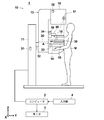
- FIG. 1 is a schematic configuration diagram of a breast image photographing display system using an embodiment of a radiographic image photographing device of the present invention.
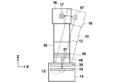
- the figure which shows the state which moved the radiation source unit in the mammography imaging display system shown in FIG. 1 is a block diagram showing a schematic configuration inside a computer of the breast image capturing and displaying system shown in FIG.
- FIG. 1 is a diagram showing a schematic configuration of the entire breast image photographing display system of the present embodiment.
- a breast image radiographing display system 1 includes a mammography apparatus 10, a computer 2 connected to the mammography apparatus 10, a monitor 3 connected to the computer 2, and an input unit. 4 is provided.
- the mammography apparatus 10 includes a base 11, a rotary shaft 12 that can move in the vertical direction (Z direction) with respect to the base 11, and can be rotated.
- the arm part 13 connected with the base 11 is provided.
- FIG. 2 shows the arm 13 viewed from the right direction in FIG.
- the arm portion 13 has an alphabet C shape, and an imaging table 14 on which a breast is installed is attached to one end, and a radiation source unit 16 is attached to the other end so as to face the imaging table 14.
- the movement of the arm unit 13 in the vertical direction is controlled by an arm controller 31 incorporated in the base 11.
- a radiographic image detector 15 such as a flat panel detector, a grid 30 for removing scattered radiation generated when the breast is irradiated with radiation, and a charge from the radiographic image detector 15.
- a detector controller 33 is provided for controlling signal readout and the like.
- a charge amplifier that converts the charge signal read from the radiation image detector 15 into a voltage signal
- a correlated double sampling circuit that samples the voltage signal output from the charge amplifier
- a circuit board provided with an AD conversion unit for converting a voltage signal into a digital signal is also installed.
- the radiation image detector 15 can repeatedly perform recording and reading of a radiation image, and may use a so-called direct type radiation image detector that directly receives radiation and generates charges. Alternatively, a so-called indirect radiation image detector that converts radiation once into visible light and converts the visible light into a charge signal may be used.
- a radiation image signal readout method a radiation image signal is read out by turning on / off a TFT (thin film transistor) switch, or by irradiating reading light.
- TFT thin film transistor
- the grid 30 is for removing scattered radiation, and is formed by alternately arranging a member that absorbs radiation and a member that transmits radiation in a striped or lattice shape. Is.
- a grid moving mechanism (not shown in FIG. 1) for moving the grid 30 in the direction of arrow A shown in FIG.
- the grid moving mechanism moves the grid 30 to the position indicated by the solid line in FIG. 1 when performing imaging using the grid 30, and indicates the position indicated by the dotted line in FIG. 1 when performing imaging without using the grid 30.
- the grid 30 is moved. It is assumed that the arm 13 is provided with a predetermined space so that the grid 30 can be retracted at a position indicated by a dotted line in FIG.
- a known actuator can be used as the grid moving mechanism. A method for controlling the grid moving mechanism will be described in detail later.
- a radiation source 17 and a radiation source controller 32 are accommodated in the radiation source unit 16.
- the radiation source controller 32 controls the timing of irradiating radiation from the radiation source 17 and the radiation generation conditions (tube current, time, tube voltage, etc.) in the radiation source 17.
- the compression plate 18 is disposed above the imaging table 14 and presses the breast to press it, the support portion 20 that supports the compression plate 18, and the support portion 20 in the vertical direction.
- a moving mechanism 19 for moving is provided. The position of the compression plate 18 and the compression pressure are controlled by the compression plate controller 34.
- the computer 2 includes a central processing unit (CPU) and a storage device such as a semiconductor memory, a hard disk, and an SSD.
- a control unit 42 and a thickness information acquisition unit 43 are configured.
- the control unit 40 outputs predetermined control signals to the various controllers 31 to 34 to control the entire system. A specific control method will be described in detail later.
- the radiation image storage unit 41 stores two radiation image signals detected by the radiation image detector 15 by photographing from two different photographing directions.
- the display control unit 42 displays a breast stereo image on the monitor 3 after performing predetermined signal processing on the radiographic image signal read from the radiographic image storage unit 41.
- the thickness information acquisition unit 43 is installed on the imaging table 14 and acquires the thickness information of the breast of the subject M in a state of being compressed by the compression plate 18.
- the thickness information in the present embodiment is information indicating the thickness of the breast in the direction perpendicular to the breast installation surface.
- the breast thickness information may be set and input by the photographer using the input unit 4, or the position information of the compression plate 18 is acquired from the compression plate controller 34, and based on the position information of the compression plate 18. Thus, the thickness information may be acquired.
- a gauge may be provided on the arm unit 13 so that the photographer can check the thickness of the breast.
- the grid moving mechanism 35 shown in FIG. 3 is provided in the imaging table 14 shown in FIG. 1 as described above, and moves the grid 30 based on the control signal output from the control unit 40 of the computer 2. It is something to be made.
- the input unit 4 is composed of a pointing device such as a keyboard and a mouse, for example, and receives input by a photographer such as predetermined imaging conditions and breast thickness information described above.
- the monitor 3 is configured to be able to display a stereo image using two radiation image signals output from the computer 2.
- a configuration for displaying a stereo image for example, a radiographic image based on two radiographic image signals is displayed using two screens, and one of the radiographic images is observed by using a half mirror or a polarizing glass. It is possible to adopt a configuration in which a stereo image is displayed by being incident on the right eye of the observer and the other radiation image is incident on the left eye of the observer.
- two radiographic images may be displayed in a superimposed manner while being shifted by a predetermined amount of parallax, and this may be configured to generate a stereo image by observing with a polarizing glass, or a parallax barrier method and a lenticular method
- a stereo image may be generated by displaying two radiation images on a stereoscopically viewable 3D liquid crystal.
- the breast of the subject M is placed on the imaging table 14, and the breast is compressed with a predetermined pressure by the compression plate 18 (S10).
- the thickness information acquisition unit 43 acquires breast thickness information (S12).
- the control unit 40 reads a preset shooting angle ⁇ for shooting a stereo image, and outputs information of the read shooting angle ⁇ to the arm controller 31.
- the present invention is not limited to this. Can be set.
- control unit 40 sends a control signal to the grid moving mechanism 35 when the grid 30 is not arranged at the position (the position indicated by the solid line in FIG. 1) when photographing using the grid 30.
- the grid 30 is moved to the position where the image is output and shooting is performed using the grid.
- the control unit 40 notifies the radiation source controller 32 and the detector controller 33.
- a control signal is output so as to perform radiation irradiation and readout of a radiographic image signal.
- radiation is emitted from the radiation source 17, and the radiation passes through the grid 30 and is then applied to the breast.
- a radiographic image obtained by photographing the breast from 0 ° direction is detected by the radiographic image detector 15, the radiographic image signal is read by the detector controller 33, and predetermined signal processing is performed on the radiographic image signal. Then, it is memorize
- the control unit 40 sets the thickness information acquired by the thickness information acquisition unit 43 in S12 in advance. It is determined whether or not it is below the threshold value (S18). And when the thickness information acquired by the thickness information acquisition part 43 is below a threshold value (S18, YES), the control part 40 outputs a control signal to the grid moving mechanism 35, and shows the dotted line shown in FIG.
- the grid 30 is moved to a position and saved (S20).
- the threshold value can be set to, for example, about 2 cm to 3 cm, but can be arbitrarily set using the input unit 4 according to the allowable reduction in sharpness due to the influence of scattered radiation.
- the control unit 40 uses the position as it is, that is, the grid 30 without moving the grid 30.
- the position in the case of performing shooting is kept (S22).
- the arm controller 31 controls the arm unit 13 to rotate + ⁇ ° with respect to the direction perpendicular to the imaging table 14, as shown in FIG. Is output. That is, in the present embodiment, the control signal is output so that the arm unit 13 is rotated by 4 ° with respect to the direction perpendicular to the imaging table 14.
- the control unit 40 applies radiation to the radiation source controller 32 and the detector controller 33 and outputs the radiation image signal.
- a control signal is output for reading.
- radiation is emitted from the radiation source 17
- a radiation image obtained by photographing the breast from the 4 ° direction is detected by the radiation image detector 15, and the radiation image signal is read by the detector controller 33.
- the signal is stored in the radiation image storage unit 41 of the computer 2 (S26).
- the two radiographic image signals stored in the radiographic image storage unit 41 are read by the display control unit 42, and after the predetermined processing is performed on these radiographic image signals in the display control unit 42, It is output to the monitor 3. Then, on the monitor 3, the radiographic image for the right eye and the radiographic image for the left eye are respectively displayed and a stereo image of the breast is displayed (S28).
- the grid 30 is used for shooting at two shooting angles. Therefore, when the subject is thick, the influence of scattered rays becomes excessive and stereoscopic viewing or It is possible to prevent a situation in which image diagnosis cannot be performed appropriately.
- the grid 30 is In the case of photographing using 400 mR of radiation from the radiation source 17, it is not necessary to consider the transmittance of the grid 30 in photographing without using the grid 30. Is emitted from the radiation source 17. Therefore, the exposure dose of the subject can be halved at this time.
- the imaging is performed. You may make it perform imaging
- photography which does not use the grid 30 about angle (theta) 4 degrees.
- the imaging angles may be the same shooting angle, for example, ⁇ 2 °. In this case, which shooting angle is used for shooting with a low dose without using the grid 30. You may make it carry out.
- the imaging target is the breast.
- the imaging target of the radiographic imaging device of the present invention is not limited to the breast.
- a part such as a hand that is relatively thin and hardly affected by scattered radiation. May be the subject of shooting.
Landscapes
- Health & Medical Sciences (AREA)
- Life Sciences & Earth Sciences (AREA)
- Medical Informatics (AREA)
- Engineering & Computer Science (AREA)
- Radiology & Medical Imaging (AREA)
- Molecular Biology (AREA)
- Biophysics (AREA)
- Nuclear Medicine, Radiotherapy & Molecular Imaging (AREA)
- Optics & Photonics (AREA)
- Pathology (AREA)
- Physics & Mathematics (AREA)
- Biomedical Technology (AREA)
- Heart & Thoracic Surgery (AREA)
- High Energy & Nuclear Physics (AREA)
- Surgery (AREA)
- Animal Behavior & Ethology (AREA)
- General Health & Medical Sciences (AREA)
- Public Health (AREA)
- Veterinary Medicine (AREA)
- Dentistry (AREA)
- Oral & Maxillofacial Surgery (AREA)
- Apparatus For Radiation Diagnosis (AREA)
Abstract
【課題】グリッドを用いてステレオ撮影を行う放射線画像撮影方法および装置において、グリッドによる放射線のケラレの影響を低減するとともに、散乱線の影響が過大になって立体視や画像診断を適切に行うことができない状況が生じるのを防止する。 【解決手段】被写体Mの厚さ情報を取得し、その厚さ情報が所定の閾値以下である場合には、2つの撮影方向のうちの一方の撮影方向についてはグリッド(30)を用いて撮影を行うとともに、他方の撮影方向についてはグリッド(30)を用いずに撮影を行い、厚さ情報が所定の閾値より大きい場合には、2つの撮影方向についてグリッド(30)を用いて撮影を行う。
Description
本発明は、被写体に対して互いに異なる複数の撮影方向から放射線をそれぞれ照射し、撮影方向毎の放射線画像を検出する放射線画像撮影方法および装置に関し、特に、被写体による散乱線を除去するためのグリッドを用いた撮影を行う放射線画像撮影方法および装置に関するものである。
従来、複数の画像を組み合わせて表示することにより、視差を利用して立体視できることが知られている。このような立体視できる画像(以下、立体視画像またはステレオ画像という)は、同一の被写体を異なる方向から撮影して取得された互いに視差のある複数の画像に基づいて生成される。
そして、このような立体視画像の生成は、デジタルカメラやテレビなどの分野だけでなく、放射線画像撮影の分野においても利用されている。すなわち、被検者に対して互いに異なる方向から放射線を照射し、その被検者を透過した放射線を放射線画像検出器によりそれぞれ検出して互いに視差のある複数の放射線画像を取得し、これらの放射線画像に基づいて立体視画像を生成することが行われている。そして、このように立体視画像を生成することによって奥行感のある放射線画像を観察することができ、より診断に適した放射線画像を観察することができる。
ここで、一般的に放射線画像撮影装置においては、被写体において散乱した散乱線が放射線画像検出器内に入射するのを防止するため、放射線画像検出器の検出面側に、散乱線を除去するためのグリッドが配置される。
このような散乱線の問題は、立体視画像を撮影する放射線画像撮影装置においても同様であり、たとえば、特許文献1においては、グリッドを使用してステレオ撮影を行う放射線画像撮影装置が提案されている。
そして、特許文献1においては、グリッドを使用してステレオ撮影を行う際、たとえば、撮影角度が10°を超える場合には、グリッドにおける放射線のケラレによって放射線画像検出器に到達する放射線の線量が減少してしまうことを考慮してグリッドを用いずに撮影を行うことが提案されている。
しかしながら、被写体が比較的厚いときにまで特許文献1のようにグリッドを用いずに撮影を行ったのでは、散乱線の影響が大きくなって鮮鋭度が非常に低下することになり、立体視される2枚の放射線画像のうちの一方の放射線画像については、被写体内の情報がほとんど欠落することになり、適切な立体視および画像診断を行うことができない問題がある。
本発明は、上記の事情に鑑み、上述したようなグリッドによる放射線のケラレの影響を低減することができるとともに、散乱線の影響が過大になって立体視や画像診断を適切に行うことができない状況が生じるのを防止することができる放射線画像撮影方法および装置を提供することを目的とする。
本発明の放射線画像撮影装置は、被写体に対して互いに異なる2つの撮影方向から放射線をそれぞれ照射する放射線照射部と、放射線照射部の放射線の照射による撮影方向毎の放射線画像をそれぞれ検出する放射線画像検出器とを備え、被写体と放射線画像検出器との間に被写体によって発生した散乱線を除去するグリッドが設けられた放射線画像撮影装置において、被写体の厚さ情報を取得する厚さ情報取得部を備え、厚さ情報が所定の閾値以下である場合には、2つの撮影方向のうちの一方の撮影方向についてはグリッドを用いて撮影を行うとともに、他方の撮影方向についてはグリッドを用いずに撮影を行い、厚さ情報が所定の閾値より大きい場合には、2つの撮影方向についてグリッドを用いて撮影を行うものであることを特徴とする。
また、上記本発明の放射線画像撮影装置においては、厚さ情報が所定の閾値以下である場合、2つの撮影方向のうち、放射線画像検出器の検出面の垂線とのなす角がより大きい方の撮影方向についてグリッドを用いずに撮影を行うものとできる。
また、厚さ情報が所定の閾値以下である場合、グリッドの用いた撮影の際の放射線の線量よりもグリッドを用いない撮影の際の放射線の線量の方が低くなるように放射線源を制御する制御部を設けることができる。
また、グリッドを移動させるための移動機構を設けることができる。
また、被写体を乳房とするとともに、乳房を圧迫する圧迫板を設け、厚さ情報取得部を、圧迫板の位置情報に基づいて厚さ情報を取得するものとできる。
また、グリッドを用いない撮影を行うか否かの選択指示を受け付ける選択指示受付部を設け、選択指示受付部においてグリッドを用いない撮影を行う指示が受け付けられた場合であって、かつ厚さ情報が所定の閾値以下である場合に、上記他方の撮影方向についてはグリッドを用いない撮影を行うようにできる。
本発明の放射線画像撮影方法は、被写体に対して互いに異なる2つの撮影方向から放射線をそれぞれ照射し、放射線の照射によって撮影方向毎の放射線画像を放射線画像検出器によりそれぞれ検出する放射線画像撮影方法であって、被写体と放射線画像検出器との間に被写体による散乱線を除去するグリッドを設けて放射線画像の撮影を行う放射線画像撮影方法において、被写体の厚さ情報を取得し、その厚さ情報が所定の閾値以下である場合には、2つの撮影方向のうちの一方の撮影方向についてはグリッドを用いて撮影を行うとともに、他方の撮影方向についてはグリッドを用いずに撮影を行い、厚さ情報が所定の閾値より大きい場合には、2つの撮影方向についてグリッドを用いて撮影を行うことを特徴とする。
本発明の放射線画像撮影方法および装置によれば、被写体の厚さ情報を取得し、その厚さ情報が所定の閾値以下である場合には、2つの撮影方向のうちの一方の撮影方向についてはグリッドを用いて撮影を行うとともに、他方の撮影方向についてはグリッドを用いずに撮影を行うようにしたので、他方の撮影方向についてはグリッドのケラレによる放射線の線量の低減を防止することができるとともに、被写体の厚さが大きくないので散乱線の影響が過大になって立体視や画像診断が適切に行われない状況が生じるのを防止することができる。なお、このとき他方の撮影方向について撮影された放射線画像は多少の散乱線の影響を受けることになるが、2枚の放射線画像を同時に観察する立体視においては、2枚の放射線画像のうちの一方のみの放射線画像の画質が多少低下したとしても、他方の放射線画像の画質が良好であれば適切な立体視画像が観察できるものと考えられる。
そして、厚さ情報が所定の閾値より大きい場合には、2つの撮影方向についてグリッドを用いて撮影を行うようにしたので、被写体が厚い場合に散乱線の影響が過大になって立体視や画像診断を適切に行うことができない状況が生じるのを防止することができる。
さらに、本発明の放射線画像撮影方法および装置においては、厚さ情報が所定の閾値以下である場合に上述したようにグリッドを用いない撮影を行うので、グリッドの用いた撮影の際の放射線の線量よりもグリッドを用いない撮影の際の放射線の線量の方を低くすることができ、これにより被検者の被曝量を低減することができる。
また、本発明の放射線画像撮影方法および装置において、グリッドを用いない撮影を行うか否かの選択指示を受け付け、グリッドを用いない撮影を行う指示が受け付けられた場合であって、かつ厚さ情報が所定の閾値以下である場合に、上記他方の撮影方向についてはグリッドを用いない撮影を行うようにした場合には、グリッドを用いない撮影を行うか否かを撮影者が任意に選択することができるので、用途や撮影者の要望に応じた撮影を行うことができる。
以下、図面を参照して本発明の放射線画像撮影装置の一実施形態を用いた乳房画像撮影表示システムについて説明する。図1は、本実施形態の乳房画像撮影表示システム全体の概略構成を示す図である。
本実施形態の乳房画像撮影表示システム1は、図1に示すように、乳房画像撮影装置10と、乳房画像撮影装置10に接続されたコンピュータ2と、コンピュータ2に接続されるモニタ3および入力部4とを備えている。
乳房画像撮影装置10は、図1に示すように、基台11と、基台11に対し上下方向(Z方向)に移動可能であり、かつ回転可能な回転軸12と、回転軸12により基台11と連結されたアーム部13を備えている。図2には、図1の右方向から見たアーム部13を示している。
アーム部13はアルファベットのCの形をしており、その一端には乳房が設置される撮影台14が、その他端には撮影台14と対向するように放射線源ユニット16が取り付けられている。アーム部13の上下方向の移動は、基台11に組み込まれたアームコントローラ31により制御される。
撮影台14の内部には、フラットパネルディテクタ等の放射線画像検出器15と、放射線が乳房に照射されることによって発生した散乱線を除去するためのグリッド30と、放射線画像検出器15からの電荷信号の読み出しなどを制御する検出器コントローラ33が備えられている。
また、撮影台14の内部には、放射線画像検出器15から読み出された電荷信号を電圧信号に変換するチャージアンプや、チャージアンプから出力された電圧信号をサンプリングする相関2重サンプリング回路や、電圧信号をデジタル信号に変換するAD変換部などが設けられた回路基板なども設置されている。
放射線画像検出器15は、放射線画像の記録と読出しを繰り返して行うことができるものであり、放射線の照射を直接受けて電荷を発生する、いわゆる直接型の放射線画像検出器を用いてもよいし、放射線を一旦可視光に変換し、その可視光を電荷信号に変換する、いわゆる間接型の放射線画像検出器を用いるようにしてもよい。また、放射線画像信号の読出方式としては、TFT(thin film transistor)スイッチをオン・オフされることによって放射線画像信号が読みだされる、いわゆるTFT読出方式のものや、読取光を照射することによって放射線画像信号が読み出される、いわゆる光読出方式のものを用いることができるが、これに限らずその他のものを用いるようにしてもよい。
グリッド30は、上述したように散乱線を除去するためのものであり、放射線を吸収する部材と、放射線を透過する部材とが縞状または格子状となるように交互に配置されて形成されたものである。
また、撮影台14内には、グリッド30を図1に示す矢印A方向に移動させるグリッド移動機構(図1においては図示省略)が設けられている。グリッド移動機構は、グリッド30を用いた撮影を行う際には、図1において実線で示す位置にグリッド30を移動し、グリッド30を用いない撮影を行う際には、図1において点線で示す位置にグリッド30を移動させるものである。なお、アーム部13には、図1において点線で示す位置にグリッド30が待避可能なように所定のスペースが設けられているものとする。グリッド移動機構としては、既知のアクチュエータを用いることができる。グリッド移動機構の制御方法については、後で詳述する。
放射線源ユニット16の中には放射線源17と放射線源コントローラ32とが収納されている。放射線源コントローラ32は、放射線源17から放射線を照射するタイミングと、放射線源17における放射線発生条件(管電流、時間、管電圧等)を制御するものである。
また、アーム部13の中央部には、撮影台14の上方に配置され、乳房を押さえつけて圧迫する圧迫板18と、その圧迫板18を支持する支持部20と、支持部20を上下方向に移動させる移動機構19が設けられている。圧迫板18の位置、圧迫圧は、圧迫板コントローラ34により制御される。
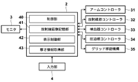
コンピュータ2は、中央処理装置(CPU)および半導体メモリやハードディスクやSSD等のストレージデバイスなどを備えており、これらのハードウェアによって、図3に示すような制御部40、放射線画像記憶部41、表示制御部42および厚さ情報取得部43が構成されている。
制御部40は、各種のコントローラ31~34に対して所定の制御信号を出力し、システム全体の制御を行うものである。具体的な制御方法については後で詳述する。
放射線画像記憶部41は、互いに異なる2つの撮影方向からの撮影によって放射線画像検出器15によって検出された2枚の放射線画像信号を記憶するものである。
表示制御部42は、放射線画像記憶部41から読み出された放射線画像信号に対して所定の信号処理を施した後、モニタ3に乳房のステレオ画像を表示させるものである。
厚さ情報取得部43は、撮影台14上に設置されて、圧迫板18によって圧迫された状態の被検者Mの乳房の厚さ情報を取得するものである。本実施形態における厚さ情報とは、乳房の設置面に対して垂直方向についての乳房の厚さを示す情報である。乳房の厚さ情報は、入力部4を用いて撮影者が設定入力するようにしてもよいし、圧迫板コントローラ34から圧迫板18の位置情報を取得し、その圧迫板18の位置情報に基づいて厚さ情報を取得するようにしてもよい。入力部4を用いて撮影者が設定入力する場合には、撮影者が乳房の厚さを確認できるようなゲージをアーム部13に設けるようにしてもよい。
なお、図3に示すグリッド移動機構35は、上述したように図1に示す撮影台14内に設けられるものであり、コンピュータ2の制御部40から出力された制御信号に基づいてグリッド30を移動させるものである。
入力部4は、たとえば、キーボードやマウスなどのポインティングデバイスから構成されるものであり、所定の撮影条件や上述した乳房の厚さ情報などの撮影者による入力を受け付けるものである。
モニタ3は、コンピュータ2から出力された2つの放射線画像信号を用いてステレオ画像を表示可能なように構成されたものである。ステレオ画像を表示する構成としては、たとえば、2つの画面を用いて2つの放射線画像信号に基づく放射線画像をそれぞれ表示させて、これらをハーフミラーや偏光グラスなどを用いることで一方の放射線画像は観察者の右目に入射させ、他方の放射線画像は観察者の左目に入射させることによってステレオ画像を表示する構成を採用することができる。または、たとえば、2つの放射線画像を所定の視差量だけずらして重ね合わせて表示し、これを偏光グラスで観察することでステレオ画像を生成する構成としてもよいし、もしくはパララックスバリア方式およびレンチキュラー方式のように、2つの放射線画像を立体視可能な3D液晶に表示することによってステレオ画像を生成する構成としてもよい。
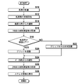
次に、本実施形態の乳房画像撮影表示システムの作用について、図4に示すフローチャートを参照しながら説明する。
まず、撮影台14の上に被検者Mの乳房が設置され、圧迫板18により乳房が所定の圧力によって圧迫される(S10)。次に、厚さ情報取得部43によって乳房の厚さ情報が取得される(S12)。
そして、撮影者によって撮影開始指示が入力されると、ステレオ画像を構成する2枚の放射線画像のうちの1枚目の放射線画像の撮影が行われる(S14)。
具体的には、まず、制御部40が、予め設定されたステレオ画像の撮影のための撮影角度θを読み出し、その読み出した撮影角度θの情報をアームコントローラ31に出力する。なお、本実施形態においては、撮影角度θの情報としてθ=0°とθ=4°が予め記憶されているものとするが、これに限らず、撮影者によって入力部4において任意の撮影角度を設定可能である。
そして、アームコントローラ31において、制御部40から出力された撮影角度θ=0°とθ=4°の情報が受け付けられ、制御部40から出力された制御信号に応じてアームコントローラ31は、まず、θ=0°の情報に基づいて、図2に示すようにアーム部13が撮影台14に対して垂直な方向となるように制御信号を出力する。
また、このとき制御部40は、グリッド30が、グリッド30を用いた撮影を行う場合の位置(図1において実線で示す位置)に配置されていない場合には、グリッド移動機構35に制御信号を出力し、グリッドを用いた撮影を行う場合の位置までグリッド30を移動させる。
そして、このアームコントローラ31から出力された制御信号に応じてアーム部13が、撮影台14に対して垂直な方向となった状態において、制御部40は、放射線源コントローラ32および検出器コントローラ33に対して放射線の照射と放射線画像信号の読出しを行うよう制御信号を出力する。この制御信号に応じて、放射線源17から放射線が射出され、その放射線はグリッド30を透過した後、乳房に照射される。そして、乳房を0°方向から撮影した放射線画像が放射線画像検出器15によって検出され、検出器コントローラ33によって放射線画像信号が読み出され、その放射線画像信号に対して所定の信号処理が施された後、コンピュータ2の放射線画像記憶部41に記憶される(S16)。
続いて、制御部40は、撮影角度θ=4°の放射線画像の撮影を行うが、このとき制御部40は、S12において厚さ情報取得部43によって取得された厚さ情報が、予め設定された閾値以下であるか否かを判断する(S18)。そして、厚さ情報取得部43によって取得された厚さ情報が閾値以下である場合には(S18,YES)、制御部40は、グリッド移動機構35に制御信号を出力し、図1に示す点線位置までグリッド30を移動させて待避させる(S20)。なお、上記閾値については、たとえば、2cm~3cm程度とすることができるが、散乱線の影響による鮮鋭度の低下の許容量に応じて入力部4を用いて任意に設定することができる。
一方、厚さ情報取得部43によって取得された厚さ情報が閾値より大きい場合には(S18,NO)、制御部40は、グリッド30を移動させることなく、そのままの位置、すなわちグリッド30を用いた撮影を行う場合の位置のままとする(S22)。
そして、制御部40は、上述したように乳房の厚さ情報に基づいてグリッド30を配置した後、撮影角度θ=4°の放射線画像の撮影を行う(S24)。
具体的には、制御部40から出力された制御信号に応じてアームコントローラ31は、図2に示すように、アーム部13を撮影台14に垂直な方向に対して+θ°回転するよう制御信号を出力する。すなわち、本実施形態においては、アーム部13を撮影台14に垂直な方向に対して4°回転するよう制御信号を出力する。
そして、アームコントローラ31から出力された制御信号に応じてアーム部13が4°回転した状態において、制御部40は、放射線源コントローラ32および検出器コントローラ33に対して放射線の照射と放射線画像信号の読出しを行うよう制御信号を出力する。そして、この制御信号に応じて、放射線源17から放射線が射出され、乳房を4°方向から撮影した放射線画像が放射線画像検出器15によって検出され、検出器コントローラ33によって放射線画像信号が読み出され、所定の信号処理が施された後、コンピュータ2の放射線画像記憶部41に記憶される(S26)。
そして、放射線画像記憶部41に記憶された2枚の放射線画像信号は、表示制御部42によって読み出され、表示制御部42においてこれらの放射線画像信号に対して所定の処理が施された後、モニタ3に出力される。そして、モニタ3において、右目用放射線画像と左目用放射線画像とがそれぞれ表示されて乳房のステレオ画像が表示される(S28)。
上記実施形態の乳房画像撮影表示システムによれば、乳房の厚さ情報を取得し、その厚さ情報が所定の閾値以下である場合には、2つの撮影角度のうちの撮影角度θ=0°についてはグリッド30を用いて撮影を行うとともに、撮影角度θ=4°についてはグリッド30を用いずに撮影を行うようにしたので、撮影角度θ=4°の撮影についてはグリッド30のケラレによる放射線の線量の低減を防止することができるとともに、被写体の厚さが大きくないので散乱線の影響が過大になって立体視や画像診断が適切に行われない状況が生じるのを防止することができる。
そして、厚さ情報が所定の閾値より大きい場合には、2つの撮影角度についてグリッド30を用いて撮影を行うようにしたので、被写体が厚い場合に散乱線の影響が過大になって立体視や画像診断を適切に行うことができない状況が生じるのを防止することができる。
また、上記実施形態においては、乳房の厚さ情報が所定の閾値以下の場合に、撮影角度θ=4°の撮影についてはグリッド30を用いないようにしたが、このとき撮影角度θ=0°の撮影の際の放射線の線量よりも、グリッド30を用いない撮影角度θ=4°の撮影の際の放射線の線量の方が低くなるように制御部40が放射線源17を制御するようにしてもよい。すなわち、グリッド30を用いない場合には、グリッド30における放射線のケラレによる放射線の線量の低減分を考慮しなくてよいので、その分だけ放射線源17から射出される放射線の線量を下げることができ、被検者Mの被曝量を減らすことができる。
具体的には、たとえば、乳房の放射線の透過率を1/20とし、グリッド30の透過率を1/2とすると、放射線画像検出器15に10mRの放射線を到達させるためには、グリッド30を用いた撮影の場合には、400mRの放射線を放射線源17から射出させる必要があるが、グリッド30を用いない撮影の場合には、グリッド30の透過率を考慮しなくてもよいので200mRの放射線を放射線源17から射出させればよいことになる。したがって、このとき被検者の被曝量も半分にすることができる。
また、上記実施形態においては、撮影角度θ=4°の撮影について、乳房の厚さ情報のみに基づいてグリッド30の有無を判断するようにしたが、さらに、グリッドを用いない撮影を行うか否かの選択指示を入力部4において受け付けるようにし、入力部4においてグリッド30を用いない撮影を行う指示が受け付けられた場合であって、かつ乳房の厚さ情報が閾値以下である場合に、撮影角度θ=4°についてグリッド30を用いない撮影を行うようにしてもよい。そして、入力部4においてグリッド30を用いない撮影を行なわない指示が受け付けられた場合には、たとえ乳房の厚さ情報が閾値以下である場合であっても、撮影角度θ=4°についても撮影角度θ=0°の撮影と同様に、グリッド30を用いた撮影を行うようにしてもよい。
また、上記実施形態においては、撮影角度θ=0°と撮影角度θ=4°とについて撮影を行うようにし、撮影角度θ=4°について乳房の厚さ情報に基づいてグリッド30を用いない撮影を行うようにしたが、たとえば2つの撮影角度として別の撮影角度を採用した場合には、2つの撮影角度のうち、放射線画像検出器15の検出面の垂線とのなす角がより大きい方の撮影角度について乳房の厚さ情報に基づいてグリッド30を用いない撮影を行うようにすることが望ましい。なお、2つの撮影角度として、たとえば±2°といったように同じ大きさの撮影角度を採用するようにしてもよく、この場合には、グリッド30を用いない低線量での撮影はどちらの撮影角度で行うようにしてもよい。
また、上記実施形態においては、撮影対象を乳房としたが、本発明の放射線画像撮影装置の撮影対象は乳房に限らず、たとえば、手など比較的厚さが薄く散乱線の影響を受けにくい部位を撮影対象としてもよい。
Claims (7)
- 被写体に対して互いに異なる2つの撮影方向から放射線をそれぞれ照射する放射線照射部と、該放射線照射部の前記放射線の照射による前記撮影方向毎の放射線画像をそれぞれ検出する放射線画像検出器とを備え、前記被写体と前記放射線画像検出器との間に前記被写体によって発生した散乱線を除去するグリッドが設けられた放射線画像撮影装置において、
前記被写体の厚さ情報を取得する厚さ情報取得部を備え、
前記厚さ情報が所定の閾値以下である場合には、前記2つの撮影方向のうちの一方の撮影方向については前記グリッドを用いて撮影を行うとともに、他方の撮影方向については前記グリッドを用いずに撮影を行い、
前記厚さ情報が前記所定の閾値より大きい場合には、前記2つの撮影方向について前記グリッドを用いて撮影を行うものであることを特徴とする放射線画像撮影装置。 - 前記厚さ情報が所定の閾値以下である場合、前記2つの撮影方向のうち、前記放射線画像検出器の検出面の垂線とのなす角がより大きい方の撮影方向について前記グリッドを用いずに撮影を行うものであることを特徴とする請求項1記載の放射線画像撮影装置。
- 前記厚さ情報が所定の閾値以下である場合、前記グリッドの用いた撮影の際の前記放射線の線量よりも前記グリッドを用いない撮影の際の前記放射線の線量の方が低くなるように放射線源を制御する制御部を備えたことを特徴とする請求項1または2記載の放射線画像撮影装置。
- 前記グリッドを移動させるための移動機構を備えたものであることを特徴とする請求項1から3いずれか1項記載の放射線画像撮影装置。
- 前記被写体が乳房であるとともに、該乳房を圧迫する圧迫板を備え、
前記厚さ情報取得部が、前記圧迫板の位置情報に基づいて前記厚さ情報を取得するものであることを特徴とする請求項1から4いずれか1項記載の放射線画像撮影装置。 - 前記グリッドを用いない撮影を行うか否かの選択指示を受け付ける選択指示受付部を備え、
前記選択指示受付部において前記グリッドを用いない撮影を行う指示が受け付けられた場合であって、かつ前記厚さ情報が所定の閾値以下である場合に、前記他方の撮影方向については前記グリッドを用いない撮影を行うものであることを特徴とする請求項1から5いずれか1項記載の放射線画像撮影装置。 - 被写体に対して互いに異なる2つの撮影方向から放射線をそれぞれ照射し、該放射線の照射によって前記撮影方向毎の放射線画像を放射線画像検出器によりそれぞれ検出する放射線画像撮影方法であって、前記被写体と前記放射線画像検出器との間に前記被写体による散乱線を除去するグリッドを設けて前記放射線画像の撮影を行う放射線画像撮影方法において、
前記被写体の厚さ情報を取得し、
該厚さ情報が所定の閾値以下である場合には、前記2つの撮影方向のうちの一方の前記撮影方向については前記グリッドを用いて撮影を行うとともに、他方の前記撮影方向については前記グリッドを用いずに撮影を行い、
前記厚さ情報が前記所定の閾値より大きい場合には、前記2つの撮影方向について前記グリッドを用いて撮影を行うことを特徴とする放射線画像撮影方法。
Applications Claiming Priority (2)
| Application Number | Priority Date | Filing Date | Title |
|---|---|---|---|
| JP2011039271A JP2012175996A (ja) | 2011-02-25 | 2011-02-25 | 放射線画像撮影方法および装置 |
| JP2011-039271 | 2011-02-25 |
Publications (1)
| Publication Number | Publication Date |
|---|---|
| WO2012114757A1 true WO2012114757A1 (ja) | 2012-08-30 |
Family
ID=46720548
Family Applications (1)
| Application Number | Title | Priority Date | Filing Date |
|---|---|---|---|
| PCT/JP2012/001240 Ceased WO2012114757A1 (ja) | 2011-02-25 | 2012-02-23 | 放射線画像撮影方法および装置 |
Country Status (2)
| Country | Link |
|---|---|
| JP (1) | JP2012175996A (ja) |
| WO (1) | WO2012114757A1 (ja) |
Cited By (2)
| Publication number | Priority date | Publication date | Assignee | Title |
|---|---|---|---|---|
| CN106175804A (zh) * | 2015-05-29 | 2016-12-07 | 佳能株式会社 | 图像处理设备和图像处理方法 |
| EP4183346A1 (en) * | 2021-11-17 | 2023-05-24 | FUJIFILM Corporation | Image processing apparatus, image processing method, and image processing program |
Families Citing this family (1)
| Publication number | Priority date | Publication date | Assignee | Title |
|---|---|---|---|---|
| ES2798306T3 (es) | 2013-03-15 | 2020-12-10 | Hologic Inc | Dispositivo de reducción de dispersión de rayos X para su uso con mamografía en 2D y 3D |
Citations (3)
| Publication number | Priority date | Publication date | Assignee | Title |
|---|---|---|---|---|
| JP2003038472A (ja) * | 2001-07-26 | 2003-02-12 | Canon Inc | 放射線画像撮影装置 |
| JP2009022536A (ja) * | 2007-07-20 | 2009-02-05 | Fujifilm Corp | 放射線画像撮像装置及び撮像方法 |
| JP2010188002A (ja) * | 2009-02-19 | 2010-09-02 | Fujifilm Corp | 放射線撮影装置 |
-
2011
- 2011-02-25 JP JP2011039271A patent/JP2012175996A/ja not_active Withdrawn
-
2012
- 2012-02-23 WO PCT/JP2012/001240 patent/WO2012114757A1/ja not_active Ceased
Patent Citations (3)
| Publication number | Priority date | Publication date | Assignee | Title |
|---|---|---|---|---|
| JP2003038472A (ja) * | 2001-07-26 | 2003-02-12 | Canon Inc | 放射線画像撮影装置 |
| JP2009022536A (ja) * | 2007-07-20 | 2009-02-05 | Fujifilm Corp | 放射線画像撮像装置及び撮像方法 |
| JP2010188002A (ja) * | 2009-02-19 | 2010-09-02 | Fujifilm Corp | 放射線撮影装置 |
Cited By (3)
| Publication number | Priority date | Publication date | Assignee | Title |
|---|---|---|---|---|
| CN106175804A (zh) * | 2015-05-29 | 2016-12-07 | 佳能株式会社 | 图像处理设备和图像处理方法 |
| EP4183346A1 (en) * | 2021-11-17 | 2023-05-24 | FUJIFILM Corporation | Image processing apparatus, image processing method, and image processing program |
| US12249046B2 (en) * | 2021-11-17 | 2025-03-11 | Fujifilm Corporation | Image processing apparatus, image processing method, and image processing program |
Also Published As
| Publication number | Publication date |
|---|---|
| JP2012175996A (ja) | 2012-09-13 |
Similar Documents
| Publication | Publication Date | Title |
|---|---|---|
| JP2012050519A (ja) | 乳房画像撮影装置 | |
| JP5490038B2 (ja) | 乳房画像撮影装置 | |
| JP5600305B2 (ja) | 放射線画像撮影方法および装置 | |
| JP2012045022A (ja) | 放射線画像撮影表示装置および放射線画像撮影表示方法 | |
| JP2012029742A (ja) | 放射線画像撮影表示方法および装置 | |
| WO2012114757A1 (ja) | 放射線画像撮影方法および装置 | |
| JP2012029759A (ja) | 放射線画像撮影表示方法および装置 | |
| JP2012024519A (ja) | 放射線画像撮影表示方法および装置 | |
| JP2012066049A (ja) | 放射線画像撮影装置および立体視画像表示方法 | |
| JP5506726B2 (ja) | 放射線画像撮影方法、並びに、放射線検出器および放射線画像撮影装置 | |
| JP2012165358A (ja) | 立体視画像表示装置 | |
| WO2012127819A1 (ja) | 3次元放射線撮影装置および方法 | |
| WO2012056695A1 (ja) | 立体視画像表示装置および方法並びにプログラム | |
| JP2012068610A (ja) | 立体視画像表示装置、放射線画像撮影表示システムおよび立体視画像表示方法 | |
| JP2012024516A (ja) | 放射線画像撮影表示方法および装置 | |
| JP2012011036A (ja) | 放射線画像撮影方法および装置 | |
| JP2013000490A (ja) | 放射線画像撮影方法および装置 | |
| JP2013000491A (ja) | 放射線画像撮影方法および装置 | |
| WO2012039121A1 (ja) | 放射線画像撮影装置および放射線画像撮影方法 | |
| JP2012070826A (ja) | 放射線画像撮影装置および方法 | |
| WO2012105188A1 (ja) | 立体視画像表示装置および方法並びにプログラム | |
| JP2013000492A (ja) | 放射線画像撮影方法および装置 | |
| JP2012050518A (ja) | 放射線画像撮影装置 | |
| WO2012120886A1 (ja) | 3次元放射線撮影装置および方法 | |
| WO2012114758A1 (ja) | 放射線画像撮影方法および装置 |
Legal Events
| Date | Code | Title | Description |
|---|---|---|---|
| 121 | Ep: the epo has been informed by wipo that ep was designated in this application |
Ref document number: 12750187 Country of ref document: EP Kind code of ref document: A1 |
|
| NENP | Non-entry into the national phase |
Ref country code: DE |
|
| 122 | Ep: pct application non-entry in european phase |
Ref document number: 12750187 Country of ref document: EP Kind code of ref document: A1 |