WO2012114724A1 - フィルタ方法、動画像符号化装置、動画像復号装置及び動画像符号化復号装置 - Google Patents
フィルタ方法、動画像符号化装置、動画像復号装置及び動画像符号化復号装置 Download PDFInfo
- Publication number
- WO2012114724A1 WO2012114724A1 PCT/JP2012/001167 JP2012001167W WO2012114724A1 WO 2012114724 A1 WO2012114724 A1 WO 2012114724A1 JP 2012001167 W JP2012001167 W JP 2012001167W WO 2012114724 A1 WO2012114724 A1 WO 2012114724A1
- Authority
- WO
- WIPO (PCT)
- Prior art keywords
- block
- filter
- ipcm block
- ipcm
- unit
- Prior art date
Links
Images


Classifications
-
- H—ELECTRICITY
- H04—ELECTRIC COMMUNICATION TECHNIQUE
- H04N—PICTORIAL COMMUNICATION, e.g. TELEVISION
- H04N19/00—Methods or arrangements for coding, decoding, compressing or decompressing digital video signals
- H04N19/10—Methods or arrangements for coding, decoding, compressing or decompressing digital video signals using adaptive coding
- H04N19/102—Methods or arrangements for coding, decoding, compressing or decompressing digital video signals using adaptive coding characterised by the element, parameter or selection affected or controlled by the adaptive coding
- H04N19/117—Filters, e.g. for pre-processing or post-processing
-
- H—ELECTRICITY
- H04—ELECTRIC COMMUNICATION TECHNIQUE
- H04N—PICTORIAL COMMUNICATION, e.g. TELEVISION
- H04N19/00—Methods or arrangements for coding, decoding, compressing or decompressing digital video signals
- H04N19/10—Methods or arrangements for coding, decoding, compressing or decompressing digital video signals using adaptive coding
- H04N19/102—Methods or arrangements for coding, decoding, compressing or decompressing digital video signals using adaptive coding characterised by the element, parameter or selection affected or controlled by the adaptive coding
- H04N19/124—Quantisation
-
- H—ELECTRICITY
- H04—ELECTRIC COMMUNICATION TECHNIQUE
- H04N—PICTORIAL COMMUNICATION, e.g. TELEVISION
- H04N19/00—Methods or arrangements for coding, decoding, compressing or decompressing digital video signals
- H04N19/10—Methods or arrangements for coding, decoding, compressing or decompressing digital video signals using adaptive coding
- H04N19/134—Methods or arrangements for coding, decoding, compressing or decompressing digital video signals using adaptive coding characterised by the element, parameter or criterion affecting or controlling the adaptive coding
- H04N19/157—Assigned coding mode, i.e. the coding mode being predefined or preselected to be further used for selection of another element or parameter
-
- H—ELECTRICITY
- H04—ELECTRIC COMMUNICATION TECHNIQUE
- H04N—PICTORIAL COMMUNICATION, e.g. TELEVISION
- H04N19/00—Methods or arrangements for coding, decoding, compressing or decompressing digital video signals
- H04N19/10—Methods or arrangements for coding, decoding, compressing or decompressing digital video signals using adaptive coding
- H04N19/169—Methods or arrangements for coding, decoding, compressing or decompressing digital video signals using adaptive coding characterised by the coding unit, i.e. the structural portion or semantic portion of the video signal being the object or the subject of the adaptive coding
- H04N19/17—Methods or arrangements for coding, decoding, compressing or decompressing digital video signals using adaptive coding characterised by the coding unit, i.e. the structural portion or semantic portion of the video signal being the object or the subject of the adaptive coding the unit being an image region, e.g. an object
- H04N19/176—Methods or arrangements for coding, decoding, compressing or decompressing digital video signals using adaptive coding characterised by the coding unit, i.e. the structural portion or semantic portion of the video signal being the object or the subject of the adaptive coding the unit being an image region, e.g. an object the region being a block, e.g. a macroblock
-
- H—ELECTRICITY
- H04—ELECTRIC COMMUNICATION TECHNIQUE
- H04N—PICTORIAL COMMUNICATION, e.g. TELEVISION
- H04N19/00—Methods or arrangements for coding, decoding, compressing or decompressing digital video signals
- H04N19/50—Methods or arrangements for coding, decoding, compressing or decompressing digital video signals using predictive coding
- H04N19/593—Methods or arrangements for coding, decoding, compressing or decompressing digital video signals using predictive coding involving spatial prediction techniques
-
- H—ELECTRICITY
- H04—ELECTRIC COMMUNICATION TECHNIQUE
- H04N—PICTORIAL COMMUNICATION, e.g. TELEVISION
- H04N19/00—Methods or arrangements for coding, decoding, compressing or decompressing digital video signals
- H04N19/60—Methods or arrangements for coding, decoding, compressing or decompressing digital video signals using transform coding
-
- H—ELECTRICITY
- H04—ELECTRIC COMMUNICATION TECHNIQUE
- H04N—PICTORIAL COMMUNICATION, e.g. TELEVISION
- H04N19/00—Methods or arrangements for coding, decoding, compressing or decompressing digital video signals
- H04N19/80—Details of filtering operations specially adapted for video compression, e.g. for pixel interpolation
- H04N19/82—Details of filtering operations specially adapted for video compression, e.g. for pixel interpolation involving filtering within a prediction loop
-
- H—ELECTRICITY
- H04—ELECTRIC COMMUNICATION TECHNIQUE
- H04N—PICTORIAL COMMUNICATION, e.g. TELEVISION
- H04N19/00—Methods or arrangements for coding, decoding, compressing or decompressing digital video signals
- H04N19/85—Methods or arrangements for coding, decoding, compressing or decompressing digital video signals using pre-processing or post-processing specially adapted for video compression
- H04N19/86—Methods or arrangements for coding, decoding, compressing or decompressing digital video signals using pre-processing or post-processing specially adapted for video compression involving reduction of coding artifacts, e.g. of blockiness
Definitions
- the present invention relates to a filtering method, a video encoding device, a video decoding device, and a video encoding / decoding device.
- the IPCM (Intra Pulse Code Modulation) block is a block having an uncompressed moving image or image sample in which a signal included in the encoded stream is indicated by a sample of luminance and chromaticity of the original image. These are used when the entropy encoding unit generates a number of bits larger than the number of bits to be reduced when encoding a block of image samples. That is, in the IPCM block, the pixel value is not compressed, and the pixel value of the original image is used as it is.
- This IPCM block is H.264. It is introduced in the H.264 / AVC video compression standard.
- the filtering process is performed on both blocks even at the boundary between the IPCM block and the non-IPCM block.
- the IPCM block is a block in which the original pixel value is used as it is. Therefore, there is a problem that the image quality of the IPCM block is reduced by performing the filtering process.
- an object of the present invention is to provide a filter method that can suppress a decrease in image quality of an IPCM block.
- a filtering method is a filtering method for performing filtering processing on a plurality of blocks included in an image, and each of the plurality of blocks is IPCM (Intra Pulse Code Modulation).
- IPCM IP Multimedia Code Modulation
- a determination step for determining whether the block is a block; a filter step for generating filtered data by performing a filtering process on a non-IPCM block that is not an IPCM block among the plurality of blocks; and the non-IPCM block An output step of outputting the filtered data as the pixel value of the IPCM block and outputting the pixel value of the IPCM block not subjected to the filtering process as the pixel value of the IPCM block.
- the filtering method according to an aspect of the present invention does not perform the filtering process on the IPCM block, it is possible to suppress the deterioration of the image quality of the IPCM block.
- the filtered data of the non-IPCM block may be generated by performing a filtering process using both the pixel value of the IPCM block and the pixel value of the non-IPCM block.
- the filtering process is a deblocking filtering process.
- the filtering process is performed on the first non-IPCM block among the first IPCM block and the first non-IPCM block adjacent to each other.
- 1st filtered data is generated, and in the output step, the first filtered data is output as the pixel value of the first non-IPCM block, and the pixel of the first IPCM block You may output the pixel value of the said 1st IPCM block in which the filter process is not performed as a value.
- the filtering process may be performed only on the non-IPCM block among the plurality of blocks, and the filtering process may not be performed on the IPCM block.
- the filtered data is generated by performing filtering on all of the plurality of blocks, and in the output step, the pixel value of the IPCM block is filtered out of the filtered data. It may be replaced with the pixel value of the IPCM block before.
- a filtering method is a filter that performs filtering processing on a boundary between adjacent IPCM blocks and non-IPCM (Intra Pulse Code Modulation) blocks that are not IPCM blocks included in an image.
- the filtering method according to one aspect of the present invention can weaken the filtering process for the IPCM block, it is possible to suppress the deterioration of the image quality of the IPCM block.
- the second filter strength may be a filter strength indicating that no filter processing is performed.
- the filtering method according to an aspect of the present invention does not perform the filtering process on the IPCM block, it is possible to suppress the deterioration of the image quality of the IPCM block.
- the first filter strength may be smaller than the filter strength determined when the non-IPCM block is a block that is intra-coded.
- the present invention is not only realized as such a filtering method, but also realized as a filter device using characteristic steps included in the filtering method as a means, or a program for causing a computer to execute such characteristic steps. It can also be realized as. Needless to say, such a program can be distributed via a non-transitory computer-readable recording medium such as a CD-ROM and a transmission medium such as the Internet.
- the present invention can be realized as a moving picture encoding method or a moving picture decoding method including such a filtering method. Further, the present invention is realized as a moving image encoding device or a moving image decoding device including such a filter device, or as a moving image encoding / decoding device including such a moving image encoding device and a moving image decoding device. It can be realized. Further, the present invention can be realized as a semiconductor integrated circuit (LSI) that realizes part or all of the functions of such a filter device, a moving image encoding device, or a moving image decoding device.
- LSI semiconductor integrated circuit
- the present invention can provide a filter method that can suppress a decrease in image quality of an IPCM block.
- FIG. 2 is a diagram illustrating a method of determining a filter strength at a block boundary between an IPCM block and a non-IPCM block in the H.264 scheme.
- FIG. 2 is a flowchart of block boundary filter processing in the H.264 scheme.
- FIG. 3 is a flowchart of filter strength determination processing in the H.264 system.
- FIG. 4 is a diagram showing filter strength in the filter method according to Embodiment 1 of the present invention.
- FIG. 5 is a flowchart of the filter method according to Embodiment 1 of the present invention.
- FIG. 6 is a block diagram of the video encoding apparatus according to Embodiment 1 of the present invention.
- FIG. 7A is a diagram showing an example of a block boundary according to Embodiment 1 of the present invention.
- FIG. 7B is a diagram showing an example of a block boundary according to Embodiment 1 of the present invention.
- FIG. 8A is a diagram showing an operation of the filter processing unit according to Embodiment 1 of the present invention.
- FIG. 8B is a diagram showing an operation of the filter processing unit according to Embodiment 1 of the present invention.
- FIG. 9 is a block diagram of the video decoding apparatus according to Embodiment 1 of the present invention.
- FIG. 10A is a diagram illustrating a configuration example of a filter processing unit according to Embodiment 1 of the present invention.
- FIG. 10B is a diagram illustrating a configuration example of the filter processing unit according to Embodiment 1 of the present invention.
- FIG. 10A is a diagram illustrating a configuration example of a filter processing unit according to Embodiment 1 of the present invention.
- FIG. 10B is a diagram illustrating a configuration example of the filter processing unit according to Embodiment 1 of the present invention.
- FIG. 10C is a diagram illustrating a configuration example of the filter processing unit according to Embodiment 1 of the present invention.
- FIG. 10D is a diagram illustrating a configuration example of a filter processing unit according to Embodiment 1 of the present invention.
- FIG. 10E is a diagram illustrating a configuration example of the filter processing unit according to Embodiment 1 of the present invention.
- FIG. 10F is a diagram illustrating a configuration example of a filter processing unit according to Embodiment 1 of the present invention.
- FIG. 10G is a diagram illustrating a configuration example of the filter processing unit according to Embodiment 1 of the present invention.
- FIG. 10H is a diagram illustrating a configuration example of a filter processing unit according to Embodiment 1 of the present invention.
- FIG. 11 is a flowchart of a modification of the filter method according to Embodiment 1 of the present invention.
- FIG. 12 is a flowchart of filter strength determination processing according to Embodiment 1 of the present invention.
- FIG. 13 is a diagram showing filter strength and block units according to Embodiment 1 of the present invention.
- FIG. 14A is a diagram illustrating an application range of a filter ON flag according to a comparative example of the present invention.
- FIG. 14B is a diagram illustrating an application range of a filter ON flag according to Embodiment 1 of the present invention.
- FIG. 15 is an overall configuration diagram of a content supply system that realizes a content distribution service.
- FIG. 16 is an overall configuration diagram of a digital broadcasting system.
- FIG. 17 is a block diagram illustrating a configuration example of a television.
- FIG. 18 is a block diagram illustrating a configuration example of an information reproducing / recording unit that reads and writes information from and on a recording medium that is an optical disk.
- FIG. 19 is a diagram illustrating a structure example of a recording medium that is an optical disk.
- FIG. 20A is a diagram illustrating an example of a mobile phone.
- FIG. 20B is a block diagram illustrating a configuration example of a mobile phone.
- FIG. 21 is a diagram showing a structure of multiplexed data.
- FIG. 22 is a diagram schematically showing how each stream is multiplexed in the multiplexed data.
- FIG. 23 is a diagram showing in more detail how the video stream is stored in the PES packet sequence.
- FIG. 21 is a diagram showing a structure of multiplexed data.
- FIG. 24 is a diagram showing the structure of TS packets and source packets in multiplexed data.
- FIG. 25 is a diagram illustrating a data structure of the PMT.
- FIG. 26 is a diagram showing an internal configuration of multiplexed data information.
- FIG. 27 shows the internal structure of the stream attribute information.
- FIG. 28 is a diagram showing steps for identifying video data.
- FIG. 29 is a block diagram illustrating a configuration example of an integrated circuit that realizes the moving picture coding method and the moving picture decoding method according to each embodiment.
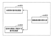
- FIG. 30 is a diagram illustrating a configuration for switching the driving frequency.
- FIG. 31 is a diagram illustrating steps for identifying video data and switching between driving frequencies.
- FIG. 32 is a diagram illustrating an example of a lookup table in which video data standards are associated with drive frequencies.
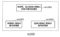
- FIG. 33A is a diagram illustrating an example of a configuration for sharing a module of a signal processing unit.
- FIG. 33B is a diagram illustrating another example of a configuration for sharing a module of a signal processing unit.
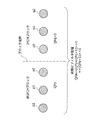
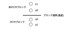
- Figure 1 shows H. It is a figure explaining the concept of the determination method of the filter strength of the filter between pixels in the boundary of an IPCM block (macroblock) and a non-IPCM block (macroblock) in a H.264 encoding and decoding system.
- FIG. 1 schematically shows a boundary between two macroblocks, one of which is a non-IPCM macroblock (left side of the figure) and the other is an IPCM macroblock (right side of the figure).
- Three circles located on the left side of FIG. 1 indicate three pixels (typically referred to as p0, p1, and p2 in order from the boundary).
- the left three pixels belong to the first block (p block) in the first unit (coding unit block, hereinafter referred to as CU block).
- CU block coding unit block
- these three pixels belong to the first macroblock of the non-IPCM type in a block in a macroblock unit (hereinafter referred to as MB block) which is a unit larger than the first unit.
- MB block macroblock unit
- three circles located on the right side of FIG. 1 indicate three pixels (typically referred to as q0, q1, and q2 in order from the boundary).
- the left three pixels belong to the second block (q block) in the first unit.
- these three pixels belong to the second macroblock of the IPCM type in the MB block.
- a CU block belonging to an IPCM type macroblock is referred to as an IPCM block
- a CU block belonging to a non-IPCM type macroblock is referred to as a non-IPCM block. That is, a non-IPCM block means a block that is not an IPCM block.
- the filter strength for the boundary between two blocks is usually set to a value qPp derived from the quantization parameter QPp of the first macroblock.
- Expression 1 shown in Expression 8-461 is used.
- This (Formula 1) shows the following calculation.
- the filter strength is designed so as to apply a stronger (smoothness) filter as the value of the quantization parameter is larger for the purpose of absorbing quantization error or the like.
- the quantization parameter QPp on the left side is a quantization parameter encoded for the first macroblock (p-side block).
- QP is used in the same meaning as the value qP used for the purpose of the filter.
- the quantization parameter QPq on the right side is a quantization parameter that should be originally applied to the second macroblock (q-side block).
- the value of the quantization parameter qPq (QPq in the figure) of the IPCM block is set to 0.
- qPq quantization parameter
- FIG. 2 shows H. 2 is a flowchart illustrating the concept of block boundary filtering described in the H.264 standard, section 8.7 “Deblocking filter process”.
- Steps S102 to S107 are processing for setting the value of the quantization parameter qP for determining the filter strength described in FIG.
- the quantization parameter QP [i] i is either 0 or 1 of the macroblock to which the block belongs is a quantum for determining the filter strength.
- Parameter qP [i] is set (steps S103 and S106).
- the quantization parameter qP of the IPCM block is set to 0 (steps S104 and S107).
- step S108 qPav is calculated by the above (formula 1).
- the determined filter strength (or determination flag for non-filtering) is applied to two blocks having a common boundary (with the same value).
- step S108 an operation using equations 8-462 to 8-467 in the standard is performed. Specifically, (1) derivation of an index for finely adjusting the filter strength set in step S101 and (2) derivation of a threshold value for edge determination are performed.
- determination of whether or not to perform filtering is performed. Specifically, this determination is performed by comparing the two threshold values (two_threths ( ⁇ , ⁇ )) derived in step S109 with the actual pixel values of p and q (the above-mentioned standard, equation (8) -468)). However, as described above, the values (or the presence / absence of execution) of the filter strength bS and the filter execution flag cannot be changed between the two blocks.
- FIG. 3 shows the order of determination (decision order) of the filter strength (bS) applied to the pixel located at the boundary between two macroblocks described in Section 8.7.2.1 of the above standard. It is a flowchart. This flowchart explains the order of determination in step S101 shown in FIG. 2, and follows the determination flow in section 8.7.2.1 of the standard.
- the boundary formed by the pixel p0 of the first block and the pixel q0 of the second block also corresponds to the boundary of the macroblock (S121). In other words, it is determined whether or not p0 and q0 are located at the macroblock boundary.
- the IPCM block is a block including a pixel value that faithfully represents an “original image” with no coding loss. Therefore, it is desirable to be able to control the filtering process at the boundary where the IPCM block is one side or the application of the filter to the IPCM block in the filtering process.
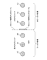
- FIG. 4 is a diagram illustrating a concept of a condition to which the filter method according to the present embodiment is applied and a method for determining the filter strength of the inter-pixel filter.
- the left three circles in the figure indicate pixels included in the first block as in FIG. Note that the description of the same elements as in FIG.
- the filtering method according to the present embodiment performs a filtering process on a plurality of blocks included in an image.
- the filtering method is applied to deblocking filtering performed on the boundary between adjacent blocks.
- deblocking filter processing an example in which the present invention is applied to deblocking filter processing will be described.
- the present invention can also be applied to in-loop filter processing (Adaptive Loop Filter) other than deblocking filter processing.
- Adaptive Loop Filter Adaptive Loop Filter
- the filtering method according to the present embodiment is different from the filtering method described in FIG. 1 in the following points.
- an unfiltered pixel value is output as the pixel value of the three pixels on the right IPCM block side in the figure.
- the first block and the second block are controlled with different handling of filters.
- the filter is applied to one (left side) block across one boundary in the figure, and the filter is not applied to the other (right side) block. In this way, control is performed with a difference in filter processing between blocks.
- the filter strength of the left block to which the filter is applied is derived using only the quantization parameter QPp of the left block. That is, the filter strength of the left non-IPCM block is derived without using the quantization parameter QPq of the right macroblock or another alternative fixed value (0 in the conventional example).
- the determination regarding the IPCM in H.264 is whether or not the IPCM macroblock is used, but this determination is performed in a prediction unit (Prediction Unit unit: PU unit) whose size is variable. That is, in the following, an IPCM block is a block that belongs to an IPCM type PU block, and a non-IPCM block is a block that belongs to a PU block that is not an IPCM type.
- PU unit Prediction Unit unit
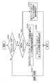
- FIG. 5 is a flowchart showing the processing order of the filter method according to the present embodiment.
- the filtering method according to the present embodiment is executed as part of the encoding process or the decoding process. Therefore, this filtering method includes a moving picture encoding apparatus shown in FIG. 6 to be described later, a coding loop in the moving picture decoding apparatus shown in FIG. 9 or a filter processing section in the decoding loop, and a control section that controls this filter. (Control Unit).
- the control unit first determines whether the type of one of the two blocks constituting the boundary is IPCM (S201). For example, in the example shown in FIG. 4, since the right PU block is an IPCM block, it is determined that one of them is an IPCM type. Specifically, the control unit performs this determination using an attribute parameter of image data such as a macro block type or a motion guarantee block size.
- the control unit determines whether the other of the two blocks is an IPCM block (S202). For example, in the case shown in FIG. 4, the right block is an IPCM block. Therefore, the control unit determines whether or not the left block, which is the other block, is an IPCM block.
- the control unit determines whether each of the plurality of blocks is an IPCM block or a non-IPCM block. Specifically, the control unit determines whether (1) the two blocks are both non-IPCM blocks (No in S201), (2) whether the two blocks are both IPCM blocks (Yes in S202), (3 ) It is determined whether one is an IPCM block and the other is a non-IPCM block (No in S202).
- the other block is an IPCM block (Yes in S202), that is, if both blocks are IPCM blocks, filter on the pixels p and q of both blocks (both the first block and the second block) Processing is not performed (S203).
- the control unit controls the filter processing unit. , The filter processing of steps S204 and S205 is executed.
- the filter processing unit performs a filter process with a predetermined intensity on pixels included in the non-IPCM block (for example, the three pixels on the left side of FIG. 4), and the pixel value after the filter process is set to the non-IPCM block
- the pixel value is output (S204).
- the filter processing unit calculates the pixel value of the filtered non-IPCM block by smoothing the pixel value of the non-IPCM block and the pixel value of the IPCM block.
- the filter processing unit outputs unfiltered pixel values to the pixels (q-side pixels q0, q1,%) Included in the IPCM block (S205).
- the following two cases are assumed to output the unfiltered pixel value.
- the first method is a method of performing the filtering process on the non-IPCM block and outputting the original pixel value without performing the filtering process on the IPCM block.
- the second method performs filtering for both the non-IPCM block and the IPCM block, and replaces the pixel value of the IPCM block with the original pixel value before the filtering process among the pixel values after the filtering process.
- This is a method of outputting the pixel value after the image.
- the pixel value of the output IPCM block is the original pixel value before the filtering process is performed.
- filtering method can also be understood as providing control with a difference in the filtering method (filter strength, filter presence / absence or number of applied pixels) between one block and the other block.
- step S201 If both blocks are non-IPCM blocks in step S201 (No in S201), the control unit performs a normal filter operation (S206). That is, the control unit executes the filter process with a predetermined filter strength for both blocks.
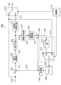
- FIG. 6 is a functional block diagram of the moving picture coding apparatus 100 according to the present embodiment.
- the moving image encoding apparatus 100 shown in FIG. 6 generates an encoded bit stream 132 by encoding the input image signal 120.
- the moving image encoding apparatus 100 includes a subtractor 101, an orthogonal transform unit 102, a quantization unit 103, an inverse quantization unit 104, an inverse orthogonal transform unit 105, an adder 106, a filter processing unit 115, , A memory 109, a prediction unit 110, a variable length encoding unit 111, a selection unit 112, and a control unit 113.
- the subtractor 101 generates a residual signal 121 by calculating a difference between the input image signal 120 and the predicted image signal 130.
- the orthogonal transform unit 102 generates a transform coefficient 122 by performing orthogonal transform on the residual signal 121.
- the quantization unit 103 generates a quantization coefficient 123 by quantizing the transform coefficient 122.
- the inverse quantization unit 104 generates a transform coefficient 124 by inversely quantizing the quantization coefficient 123.
- the inverse orthogonal transform unit 105 generates a decoded residual signal 125 by performing inverse orthogonal transform on the transform coefficient 124.
- the adder 106 adds the decoded residual signal 125 and the predicted image signal 130 to generate a decoded image signal 126.
- the filter processing unit 115 generates an image signal 128 by performing a filtering process on the decoded image signal 126, and stores the generated image signal 128 in the memory 109.
- the prediction unit 110 generates a predicted image signal 130 by selectively performing an intra prediction process and an inter prediction process using the image signal 128 stored in the memory 109.
- variable length coding unit 111 generates a coded signal 131 by performing variable length coding (entropy coding) on the quantization coefficient 123.
- the selection unit 112 selects the input image signal 120.
- the selection unit 112 selects the encoded signal 131, and uses the selected signal as the encoded bit stream 132. Output.
- the control unit 113 controls the filter processing unit 115 and the selection unit 112.
- the orthogonal transform unit 102 and the quantization unit 103 are an example of a transform and quantization unit that generates a quantization coefficient by performing transform processing and quantization processing on the residual signal.
- the variable length encoding unit 111 is an example of an encoding unit that generates an encoded signal by encoding a quantized coefficient.
- the inverse quantization unit 104 and the inverse orthogonal transform unit 105 are an example of an inverse quantization and inverse transform unit that generates a decoded residual signal by performing an inverse quantization process and an inverse transform process on a quantized coefficient.
- the main components are the control unit 113 and the filter processing unit 115 in particular.
- the filtering method according to the present embodiment is executed as part of the encoding and decoding processes. Therefore, the filter processing unit 115 is arranged in the preceding stage of the memory 109 that holds a reference image or the like. Then, the filter processing unit 115 stores the result of executing the filter process (or the result of not executing the filter) in the memory 109 in the loop.
- the filter processing unit 115 is an H.264 called a “Loop filter”. It is the same as the filter in H.264.
- the filter processing unit 115 has two input systems.
- the first input signal is the decoded image signal 126 indicating the pixel value of the non-IPCM block
- the second input signal is the input image signal 120 indicating the pixel value of the IPCM block.
- the decoded image signal 126 is a restored encoded image signal that has been subjected to transformation processing, quantization processing, inverse quantization processing, and inverse transformation processing.
- the input image signal 120 is an original image signal that does not go through the encoding process and the decoding process.
- the filter processing unit 115 outputs the original pixel value that has not been subjected to the filtering process for the pixels of the IPCM block, performs the filtering process for the pixels of the non-IPCM block, and performs the filtering process. Output the value.
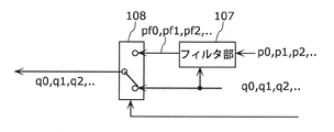
- the filter processing unit 115 includes a filter unit 107 and a selection unit 108.
- the filter unit 107 generates an image signal 127 by performing a filtering process on the decoded image signal 126.
- the selection unit 108 selects the image signal 127 when the target block is an IPCM block, and selects the input image signal 120 when the target block is a non-IPCM block, and outputs the selected signal as the image signal 128.
- FIG. 7A and 7B are diagrams illustrating pixels at the boundary between two blocks.
- the two blocks are adjacent in the horizontal direction.
- the left block including pixels from p0 to pn is referred to as a first block.
- This first block is a non-IPCM block.
- the other block is called a second block.
- This second block is an IPCM block.
- the filter processing of the present embodiment can also be applied to the case where the IPCM block and the non-IPCM block are adjacent in the vertical direction, as shown in FIG. 7B.
- FIG. 8A and 8B are diagrams illustrating the operation of the filter processing unit 115 when the filter processing is performed on the pixels p [i] and q [j] included in the two blocks illustrated in FIG. 7A. That is, the first block belongs to the non-IPCM block, and the second block belongs to the IPCM block.
- the filter processing unit 115 performs the operations shown in FIGS. 8A and 8B according to the control signal from the control unit 113.
- FIG. 8A is a diagram illustrating the operation of the filter processing unit 115 for non-IPCM blocks. This operation corresponds to step S204 shown in FIG. That is, the filter processing unit 115 uses the pixel values of both the pixel values (p0, p1%) Of the first block and the pixel values (q0, q1. The output results pf0, pf1,... Of the pixels corresponding to the blocks are calculated.
- FIG. 8B is a diagram illustrating the operation of the filter processing unit 115 for the IPCM block. This operation corresponds to step S205 shown in FIG. That is, the filter processing unit 115 outputs the same value (unfiltered pixel value) as the input q0, q1, and q2 values for the pixels of the second block.
- FIG. 9 is a functional block diagram of the video decoding device according to the present embodiment.
- the encoded bit stream 232 is, for example, the encoded bit stream 132 generated by the moving image encoding apparatus 100.
- the moving picture decoding apparatus 200 includes an inverse quantization unit 204, an inverse orthogonal transform unit 205, an adder 206, a filter processing unit 215, a memory 209, a prediction unit 210, a variable length decoding unit 211, and a distribution.
- the distribution unit 212 supplies the encoded bit stream 232 to the filter processing unit 215 when the target block is an IPCM block, and supplies the encoded bit stream 232 to the variable length decoding unit 211 when the target block is a non-IPCM block. Supply.
- variable length decoding unit 211 generates a quantized coefficient 223 by performing variable length decoding (entropy decoding) on the encoded bit stream 232.
- the inverse quantization unit 204 generates a transform coefficient 224 by inverse quantization of the quantization coefficient 223.
- the inverse orthogonal transform unit 205 generates a decoded residual signal 225 by performing inverse orthogonal transform on the transform coefficient 224.
- the adder 206 adds the decoded residual signal 225 and the predicted image signal 230 to generate a decoded image signal 226.
- the filter processing unit 215 generates an image signal 228 by performing a filtering process on the decoded image signal 226, and stores the generated image signal 228 in the memory 209.
- the filter processing unit 215 includes a filter unit 207 and a selection unit 208.
- the filter unit 207 generates an image signal 227 by performing a filtering process on the decoded image signal 226.
- the selection unit 208 selects the image signal 227.
- the selection unit 208 selects the encoded bitstream 232 and outputs the selected signal as the image signal 228. .
- the image signal 228 stored in the memory 209 is output as the output image signal 220.
- the prediction unit 210 generates the predicted image signal 230 by selectively performing the intra prediction process and the inter prediction process using the image signal 228 stored in the memory 209.
- the control unit 213 controls the filter processing unit 215 and the distribution unit 212.
- variable length decoding unit 211 is an example of a decoding unit that generates a quantized coefficient by decoding the encoded bitstream, and the inverse quantization unit 204 and the inverse orthogonal transform unit 205 perform inverse quantization on the quantized coefficient. It is an example of the inverse quantization and inverse transformation part which produces
- the operation of the filter processing unit 215 is the same as the operation of the filter processing unit 115 of the moving image coding apparatus 100.
- the control unit 213 determines whether or not the type of the PU unit of the first block or the second block is IPCM from the encoded bitstream 232 that is the input code string, the moving image. Although different from the control unit 113 included in the encoding device 100, other functions are the same.
- FIG. 10A to FIG. 10H are diagrams showing possible forms of the input / output relationship of the filters of the filter processing units 115 and 215 according to the present embodiment.
- the filter units 107 and 207 may include a plurality of filter units 301 and 302 connected in series.
- the first filter unit 301 and the second filter unit 302 may perform different processes. In this case, for example, for the IPCM block, all filter processing is bypassed.
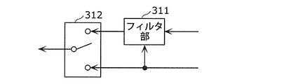
- the filter unit 311 may perform filter processing using both input signals.
- the selection unit 312 outputs an unfiltered value for the IPCM block, and outputs a value after being filtered by the filter unit 311 for the non-IPCM block.
- different filter processing may be performed on the IPCM block and the non-IPCM block.
- different filter processes are filter processes with different filter strengths.
- the filter strength for the IPCM block may be weaker than the filter strength for the non-IPCM block.
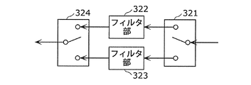
- the distribution unit 321 outputs the input signal to the filter unit 322 when the target block is a non-IPCM block, and outputs the input signal to the filter unit 323 when the target block is a non-IPCM block.
- the input signal includes both the decoded image signal 126 and the input image signal 120 described above.
- the filter unit 322 generates a pixel value of the target block by performing filter processing with the first filter strength using the input signal.
- the filter unit 323 generates a pixel value of the target block by performing filter processing with a second filter strength that is weaker than the first filter strength.
- the selection unit 324 When the target block is a non-IPCM block, the selection unit 324 outputs the pixel value of the target block after being filtered by the filter unit 322, and when the target block is an IPCM block, after being filtered by the filter unit 323 The pixel value of the target block is output.
- the processing for the IPCM block may not be performed in the first place.
- the distribution unit 331 outputs the input signal to the filter unit 332 when the target block is a non-IPCM block, and outputs the input signal to the selection unit 333 when the target block is a non-IPCM block.
- the selection unit 333 outputs the pixel value of the target block after being filtered by the filter unit 332.
- the selection unit 333 outputs the target of the signals from the distribution unit 331. Output the pixel value of the block.
- the input side may be switched instead of switching the output side of the filter unit.
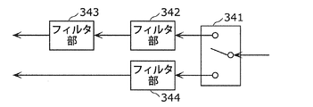
- the number of stages of filter units for the IPCM block and the non-IPCM block may be different.
- the distribution unit 341 outputs the input signal to the filter unit 342 when the target block is a non-IPCM block, and outputs the input signal to the filter unit 344 when the target block is a non-IPCM block.
- the filter unit 342 performs filter processing using the input signal.
- the filter unit 343 performs filter processing using the signal after the filter processing by the filter unit 342, and outputs the pixel value of the target block after the filter processing.
- the filter unit 344 performs filter processing using the input signal, and outputs the pixel value of the target block after the filter processing. Note that the filter process performed by the filter unit 344 may be the same as or different from the filter process performed by the filter unit 342 or the filter process performed by the filter unit 343.
- the output side of the filter unit may be switched.
- the filter unit 351 performs filter processing using the first input signal.
- the filter unit 352 performs a filter process using the signal after the filter process by the filter unit 351, and outputs the pixel value of the target block after the filter process.
- the filter unit 353 performs filter processing using the second input signal, and outputs the pixel value of the target block after the filter processing.
- the selection unit 354 outputs the pixel value of the target block after being filtered by the filter unit 352, and when the target block is an IPCM block, after being filtered by the filter unit 353 The pixel value of the target block is output.
- outputting an unfiltered value includes replacing the pixel value pf resulting from the filtering with the original input value p and outputting the result.
- one of the two systems may be subjected to the other filtering process using the signal after the filtering process.
- the filter unit 361 performs a filter process using the second input signal.
- the filter unit 362 performs filter processing using the first input signal and the signal after being filtered by the filter unit 361.
- the selection unit 363 outputs the pixel value of the target block after being filtered by the filter unit 362.
- the target block is an IPCM block, after being filtered by the filter unit 361 The pixel value of the target block is output.
- the selection unit 363 when the target block is an IPCM block, the selection unit 363 outputs the pixel value of the target block after being filtered by the filter unit 362, and when the target block is a non-IPCM block, the selection unit 363 performs the filtering process by the filter unit 361. After that, the pixel value of the target block may be output.
- a value once stored in the memory 373 may be used as an input.
- the selection unit 371 selects one of the input signal and the signal held in the memory 373.
- the filter unit 372 performs filter processing using the signal selected by the selection unit 371.
- the filter processing unit 115 only needs to be able to realize a function of “outputting a value not subjected to filter processing to the pixels of the IPCM block” as a result.
- FIG. 11 is a flowchart showing the operation of a modification of the filter method according to the present embodiment.
- steps S204 and S205 shown in FIG. 5 the filter is applied to the non-IPCM block and the unfiltered pixel value is output to the IPCM block.
- This is realized by the following steps. May be. That is, the processing shown in FIG. 11 may be performed instead of steps S204 and S205 shown in FIG.
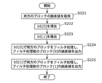
- the pixel values of the first block (block [0]) and the second block (block y [1]) adjacent to each other are acquired (S221).
- the first block is a non-IPCM block
- the second block is an IPCM block.
- the filter strength bS [0] applied to the first block and the filter strength bS [1] applied to the second block are derived (S222 and S223).
- the filter strength bS [0] and the filter strength bS [1] indicate different strengths.
- only one filter strength is set for one block boundary.
- the filter strength for the IPCM block is set to be weaker than the filter strength for the non-IPCM block.
- filter processing is performed on both blocks with the filter strength bS [0], and the pixel value of the first block after the filter processing is output (S224).
- filter processing is performed on both blocks with the filter strength bS [1], and the pixel value of the second block after the filter processing is output (S225).
- a flag (filterSamplesFlag) for controlling whether to perform filtering may be derived for each block.
- the filter method according to the present embodiment performs the filter process with the second filter strength different from the first filter strength while performing the filter process with the first filter strength in one block. Can be executed. Moreover, the said filter method can implement
- FIG. 12 is a flowchart of another modification of the filter method according to the present embodiment.
- step S401 is added to the process shown in FIG.
- step S401 is added to give an appropriate filter strength to an IPCM block that is determined to be an intra-predicted block.
- step S401 it is determined whether at least one of the first block and the second block is an IPCM block.
- the filter strength itself means the strongest strength without any other determination conditions.
- one block is an IPCM block.
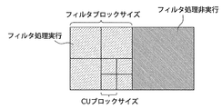
- FIG. 13 is a diagram showing the filter strength determined by the filter method according to the present embodiment and the block unit for determining the boundary.
- FIG. 14A and 14B are diagrams for explaining a situation in which the application range of the filter ON flag is expanded by the handling of the IPCM block according to the present embodiment.
- FIG. 14A shows a case where the method of the present embodiment is not applied as a comparative example.
- FIG. 14B shows a case where the method of the present embodiment is applied.
- the application range of the filter ON flag can be expanded by using the filter method according to the present embodiment.
- the filter processing unit or the control unit uses the implicit code interpretation rule of determination that “IPCM block is not filtered” in the in-loop filter processing. .
- FIGS. 14A and 14B it is possible to specify whether to enable or disable the filter in a larger range with respect to the code string.
- the filter method according to the present embodiment can reduce the bit amount.
- division of functional blocks in the block diagram is an example, and a plurality of functional blocks can be realized as one functional block, a single functional block can be divided into a plurality of functions, or some functions can be transferred to other functional blocks. May be.
- functions of a plurality of functional blocks having similar functions may be processed in parallel or time-division by a single hardware or software.
- the order in which the plurality of steps included in the filtering method are executed is for illustration in order to specifically describe the present invention, and may be in an order other than the above. Moreover, a part of the above steps may be executed simultaneously (in parallel) with other steps.
- steps S201 and S202 shown in FIG. 5 is not limited to this order. That is, as a result, when one block is included in the IPCM block and the other block is not included in the IPCM block among the two blocks sandwiching the boundary, the processes of steps S204 and S205 may be executed. Further, the order of steps SS204 and S205 may be arbitrary.
- step S224 is after step S222 and step S225 is after step S223, the order of steps S222 to S225 may be arbitrary.
- the storage medium may be any medium that can record a program, such as a magnetic disk, an optical disk, a magneto-optical disk, an IC card, and a semiconductor memory.
- the system has an image encoding / decoding device including an image encoding device using an image encoding method and an image decoding device using an image decoding method.
- image encoding / decoding device including an image encoding device using an image encoding method and an image decoding device using an image decoding method.
- Other configurations in the system can be appropriately changed according to circumstances.
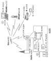
- FIG. 15 is a diagram showing an overall configuration of a content supply system ex100 that realizes a content distribution service.
- the communication service providing area is divided into desired sizes, and base stations ex106, ex107, ex108, ex109, and ex110, which are fixed wireless stations, are installed in each cell.
- the content supply system ex100 includes a computer ex111, a PDA (Personal Digital Assistant) ex112, a camera ex113, a mobile phone ex114, a game machine ex115 via the Internet ex101, the Internet service provider ex102, the telephone network ex104, and the base stations ex106 to ex110. Etc. are connected.
- PDA Personal Digital Assistant
- each device may be directly connected to the telephone network ex104 without going through the base stations ex106 to ex110 which are fixed wireless stations.
- the devices may be directly connected to each other via short-range wireless or the like.
- the camera ex113 is a device that can shoot moving images such as a digital video camera
- the camera ex116 is a device that can shoot still images and movies such as a digital camera.
- the mobile phone ex114 is a GSM (registered trademark) (Global System for Mobile Communications) method, a CDMA (Code Division Multiple Access) method, a W-CDMA (Wideband-Code Division MultipleL), or a W-CDMA (Wideband-Code Division MultipleT method). It may be a system, HSPA (High Speed Packet Access) mobile phone, PHS (Personal Handyphone System), or the like.
- the camera ex113 and the like are connected to the streaming server ex103 through the base station ex109 and the telephone network ex104, thereby enabling live distribution and the like.
- live distribution content that is shot by the user using the camera ex113 (for example, music live video) is encoded as described in the above embodiments (that is, the image encoding of the present invention).
- Function as a device and transmit to the streaming server ex103.
- the streaming server ex103 streams the content data transmitted to the requested client.
- the client include a computer ex111, a PDA ex112, a camera ex113, a mobile phone ex114, a game machine ex115, and the like that can decode the encoded data.
- Each device that receives the distributed data decodes the received data and reproduces it (that is, functions as the image decoding device of the present invention).
- the encoded processing of the captured data may be performed by the camera ex113, the streaming server ex103 that performs the data transmission processing, or may be performed in a shared manner.
- the decryption processing of the distributed data may be performed by the client, the streaming server ex103, or may be performed in a shared manner.
- still images and / or moving image data captured by the camera ex116 may be transmitted to the streaming server ex103 via the computer ex111.
- the encoding process in this case may be performed by any of the camera ex116, the computer ex111, and the streaming server ex103, or may be performed in a shared manner.
- encoding / decoding processes are generally performed by the computer ex111 and the LSI ex500 included in each device.
- the LSI ex500 may be configured as a single chip or a plurality of chips.
- moving image encoding / decoding software is incorporated into some recording media (CD-ROM, flexible disk, hard disk, etc.) that can be read by the computer ex111 and the like, and encoding / decoding processing is performed using the software May be.
- moving image data acquired by the camera may be transmitted.
- the moving image data at this time is data encoded by the LSI ex500 included in the mobile phone ex114.
- the streaming server ex103 may be a plurality of servers or a plurality of computers, and may process, record, and distribute data in a distributed manner.
- the encoded data can be received and reproduced by the client.
- the information transmitted by the user can be received, decrypted and reproduced by the client in real time, and even a user who does not have special rights or facilities can realize personal broadcasting.
- the digital broadcast system ex200 also includes at least the moving image encoding device (image encoding device) or the moving image decoding according to each of the above embodiments. Any of the devices (image decoding devices) can be incorporated.
- the broadcasting station ex201 multiplexed data obtained by multiplexing music data and the like on video data is transmitted to a communication or satellite ex202 via radio waves.
- This video data is data encoded by the moving image encoding method described in the above embodiments (that is, data encoded by the image encoding apparatus of the present invention).
- the broadcasting satellite ex202 transmits a radio wave for broadcasting, and this radio wave is received by a home antenna ex204 capable of receiving satellite broadcasting.
- the received multiplexed data is decoded and reproduced by an apparatus such as the television (receiver) ex300 or the set top box (STB) ex217 (that is, functions as the image decoding apparatus of the present invention).
- a reader / recorder ex218 that reads and decodes multiplexed data recorded on a recording medium ex215 such as a DVD or a BD, encodes a video signal on the recording medium ex215, and in some cases multiplexes and writes it with a music signal. It is possible to mount the moving picture decoding apparatus or moving picture encoding apparatus shown in the above embodiments. In this case, the reproduced video signal is displayed on the monitor ex219, and the video signal can be reproduced in another device or system using the recording medium ex215 on which the multiplexed data is recorded.
- a moving picture decoding apparatus may be mounted in a set-top box ex217 connected to a cable ex203 for cable television or an antenna ex204 for satellite / terrestrial broadcasting and displayed on the monitor ex219 of the television. At this time, the moving picture decoding apparatus may be incorporated in the television instead of the set top box.
- FIG. 17 is a diagram illustrating a television (receiver) ex300 that uses the video decoding method and the video encoding method described in each of the above embodiments.
- the television ex300 obtains or outputs multiplexed data in which audio data is multiplexed with video data via the antenna ex204 or the cable ex203 that receives the broadcast, and demodulates the received multiplexed data.
- the modulation / demodulation unit ex302 that modulates multiplexed data to be transmitted to the outside, and the demodulated multiplexed data is separated into video data and audio data, or the video data and audio data encoded by the signal processing unit ex306 Is provided with a multiplexing / separating unit ex303.
- the television ex300 decodes each of the audio data and the video data, or encodes the respective information.
- the audio signal processing unit ex304 and the video signal processing unit ex305 (function as the image encoding device or the image decoding device of the present invention).
- the television ex300 includes an interface unit ex317 including an operation input unit ex312 that receives an input of a user operation.
- the television ex300 includes a control unit ex310 that controls each unit in an integrated manner, and a power supply circuit unit ex311 that supplies power to each unit.
- the interface unit ex317 includes a bridge ex313 connected to an external device such as a reader / recorder ex218, a recording unit ex216 such as an SD card, and an external recording such as a hard disk.
- a driver ex315 for connecting to a medium, a modem ex316 for connecting to a telephone network, and the like may be included.
- the recording medium ex216 is capable of electrically recording information by using a nonvolatile / volatile semiconductor memory element to be stored.
- Each part of the television ex300 is connected to each other via a synchronous bus.
- the television ex300 receives a user operation from the remote controller ex220 or the like, and demultiplexes the multiplexed data demodulated by the modulation / demodulation unit ex302 by the multiplexing / demultiplexing unit ex303 based on the control of the control unit ex310 having a CPU or the like. Furthermore, in the television ex300, the separated audio data is decoded by the audio signal processing unit ex304, and the separated video data is decoded by the video signal processing unit ex305 using the decoding method described in the above embodiments.
- the decoded audio signal and video signal are output from the output unit ex309 to the outside.
- these signals may be temporarily stored in the buffers ex318, ex319, etc. so that the audio signal and the video signal are reproduced in synchronization.
- the television ex300 may read multiplexed data from recording media ex215 and ex216 such as a magnetic / optical disk and an SD card, not from broadcasting. Next, a configuration in which the television ex300 encodes an audio signal or a video signal and transmits the signal to the outside or writes it to a recording medium will be described.
- the television ex300 receives a user operation from the remote controller ex220 or the like, and encodes an audio signal with the audio signal processing unit ex304 based on the control of the control unit ex310, and converts the video signal with the video signal processing unit ex305. Encoding is performed using the encoding method described in (1).
- the encoded audio signal and video signal are multiplexed by the multiplexing / demultiplexing unit ex303 and output to the outside. When multiplexing, these signals may be temporarily stored in the buffers ex320 and ex321 so that the audio signal and the video signal are synchronized.
- a plurality of buffers ex318, ex319, ex320, and ex321 may be provided as illustrated, or one or more buffers may be shared. Further, in addition to the illustrated example, data may be stored in the buffer as a buffer material that prevents system overflow and underflow, for example, between the modulation / demodulation unit ex302 and the multiplexing / demultiplexing unit ex303.
- the television ex300 has a configuration for receiving AV input of a microphone and a camera, and performs encoding processing on the data acquired from them. Also good.
- the television ex300 has been described as a configuration that can perform the above-described encoding processing, multiplexing, and external output, but these processing cannot be performed, and only the above-described reception, decoding processing, and external output are possible. It may be a configuration.
- the decoding process or the encoding process may be performed by either the television ex300 or the reader / recorder ex218.
- the reader / recorder ex218 may be shared with each other.
- FIG. 18 shows a configuration of the information reproducing / recording unit ex400 when data is read from or written to an optical disk.
- the information reproducing / recording unit ex400 includes elements ex401, ex402, ex403, ex404, ex405, ex406, and ex407 described below.
- the optical head ex401 irradiates a laser spot on the recording surface of the recording medium ex215 that is an optical disc to write information, and detects information reflected from the recording surface of the recording medium ex215 to read the information.
- the modulation recording unit ex402 electrically drives a semiconductor laser built in the optical head ex401 and modulates the laser beam according to the recording data.
- the reproduction demodulator ex403 amplifies the reproduction signal obtained by electrically detecting the reflected light from the recording surface by the photodetector built in the optical head ex401, separates and demodulates the signal component recorded on the recording medium ex215, and is necessary. To play back information.
- the buffer ex404 temporarily holds information to be recorded on the recording medium ex215 and information reproduced from the recording medium ex215.
- the disk motor ex405 rotates the recording medium ex215.
- the servo control unit ex406 moves the optical head ex401 to a predetermined information track while controlling the rotational drive of the disk motor ex405, and performs a laser spot tracking process.
- the system control unit ex407 controls the entire information reproduction / recording unit ex400.
- the system control unit ex407 uses various types of information held in the buffer ex404, and generates and adds new information as necessary, and the modulation recording unit ex402, the reproduction demodulation unit This is realized by recording / reproducing information through the optical head ex401 while operating the ex403 and the servo control unit ex406 in a coordinated manner.
- the system control unit ex407 is composed of, for example, a microprocessor, and executes these processes by executing a read / write program.
- the optical head ex401 has been described as irradiating a laser spot, but it may be configured to perform higher-density recording using near-field light.
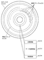
- FIG. 19 shows a schematic diagram of a recording medium ex215 that is an optical disk.
- Guide grooves grooves
- address information indicating the absolute position on the disc is recorded in advance on the information track ex230 by changing the shape of the groove.
- This address information includes information for specifying the position of the recording block ex231 that is a unit for recording data, and the recording block is specified by reproducing the information track ex230 and reading the address information in a recording or reproducing apparatus.
- the recording medium ex215 includes a data recording area ex233, an inner peripheral area ex232, and an outer peripheral area ex234.
- the area used for recording the user data is the data recording area ex233, and the inner circumference area ex232 and the outer circumference area ex234 arranged on the inner circumference or outer circumference of the data recording area ex233 are used for specific purposes other than user data recording. Used.
- the information reproducing / recording unit ex400 reads / writes encoded audio data, video data, or multiplexed data obtained by multiplexing these data with respect to the data recording area ex233 of the recording medium ex215.
- an optical disk such as a single-layer DVD or BD has been described as an example.
- the present invention is not limited to these, and an optical disk having a multilayer structure and capable of recording other than the surface may be used.
- an optical disc with a multi-dimensional recording / reproducing structure such as recording information using light of different wavelengths in the same place on the disc, or recording different layers of information from various angles. It may be.
- the car ex210 having the antenna ex205 can receive data from the satellite ex202 and the like, and the moving image can be reproduced on a display device such as the car navigation ex211 that the car ex210 has.
- the configuration of the car navigation ex211 may be, for example, a configuration in which a GPS receiver is added in the configuration illustrated in FIG.
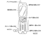
- FIG. 20A is a diagram showing the mobile phone ex114 using the moving picture decoding method and the moving picture encoding method described in the above embodiment.
- the mobile phone ex114 includes an antenna ex350 for transmitting and receiving radio waves to and from the base station ex110, a camera unit ex365 capable of taking video and still images, a video captured by the camera unit ex365, a video received by the antenna ex350, and the like Is provided with a display unit ex358 such as a liquid crystal display for displaying the decrypted data.
- the mobile phone ex114 further includes a main body unit having an operation key unit ex366, an audio output unit ex357 such as a speaker for outputting audio, an audio input unit ex356 such as a microphone for inputting audio,
- a main body unit having an operation key unit ex366, an audio output unit ex357 such as a speaker for outputting audio, an audio input unit ex356 such as a microphone for inputting audio
- an audio input unit ex356 such as a microphone for inputting audio
- the memory unit ex367 for storing encoded data or decoded data such as still images, recorded audio, received video, still images, mails, or the like, or an interface unit with a recording medium for storing data
- a slot portion ex364 is provided.
- the cellular phone ex114 has a power supply circuit ex361, an operation input control unit ex362, and a video signal processing unit ex355 for a main control unit ex360 that comprehensively controls each part of the main body including the display unit ex358 and the operation key unit ex366.
- a camera interface unit ex363, an LCD (Liquid Crystal Display) control unit ex359, a modulation / demodulation unit ex352, a multiplexing / demultiplexing unit ex353, an audio signal processing unit ex354, a slot unit ex364, and a memory unit ex367 are connected to each other via a bus ex370. ing.
- the power supply circuit unit ex361 starts up the mobile phone ex114 in an operable state by supplying power from the battery pack to each unit.
- the mobile phone ex114 converts the audio signal collected by the audio input unit ex356 in the voice call mode into a digital audio signal by the audio signal processing unit ex354 based on the control of the main control unit ex360 having a CPU, a ROM, a RAM, and the like. This is subjected to spectrum spread processing by the modulation / demodulation unit ex352, digital-analog conversion processing and frequency conversion processing by the transmission / reception unit ex351, and then transmitted via the antenna ex350.
- the mobile phone ex114 amplifies the received data received through the antenna ex350 in the voice call mode, performs frequency conversion processing and analog-digital conversion processing, performs spectrum despreading processing in the modulation / demodulation unit ex352, and performs voice signal processing unit After converting to an analog audio signal at ex354, this is output from the audio output unit ex357.
- the text data of the e-mail input by operating the operation key unit ex366 of the main unit is sent to the main control unit ex360 via the operation input control unit ex362.
- the main control unit ex360 performs spread spectrum processing on the text data in the modulation / demodulation unit ex352, performs digital analog conversion processing and frequency conversion processing in the transmission / reception unit ex351, and then transmits the text data to the base station ex110 via the antenna ex350.
- almost the reverse process is performed on the received data and output to the display unit ex358.
- the video signal processing unit ex355 compresses the video signal supplied from the camera unit ex365 by the moving image encoding method described in each of the above embodiments. Encode (that is, function as an image encoding apparatus of the present invention), and send the encoded video data to the multiplexing / demultiplexing unit ex353.
- the audio signal processing unit ex354 encodes the audio signal picked up by the audio input unit ex356 while the camera unit ex365 images a video, a still image, and the like, and sends the encoded audio data to the multiplexing / demultiplexing unit ex353. To do.
- the multiplexing / demultiplexing unit ex353 multiplexes the encoded video data supplied from the video signal processing unit ex355 and the encoded audio data supplied from the audio signal processing unit ex354 by a predetermined method, and is obtained as a result.
- the multiplexed data is subjected to spread spectrum processing by the modulation / demodulation unit (modulation / demodulation circuit unit) ex352, digital-analog conversion processing and frequency conversion processing by the transmission / reception unit ex351, and then transmitted through the antenna ex350.
- the multiplexing / separating unit ex353 separates the multiplexed data into a video data bit stream and an audio data bit stream, and performs video signal processing on the video data encoded via the synchronization bus ex370.
- the encoded audio data is supplied to the audio signal processing unit ex354 while being supplied to the unit ex355.
- the video signal processing unit ex355 decodes the video signal by decoding using the video decoding method corresponding to the video encoding method shown in each of the above embodiments (that is, functions as the image decoding device of the present invention). For example, video and still images included in the moving image file linked to the home page are displayed from the display unit ex358 via the LCD control unit ex359.
- the audio signal processing unit ex354 decodes the audio signal, and the audio output unit ex357 outputs the audio.
- the terminal such as the mobile phone ex114 is referred to as a transmitting terminal having only an encoder and a receiving terminal having only a decoder.
- a transmitting terminal having only an encoder
- a receiving terminal having only a decoder.
- multiplexed data in which music data or the like is multiplexed with video data is received and transmitted.
- data in which character data or the like related to video is multiplexed It may be video data itself instead of multiplexed data.
- the moving picture encoding method or the moving picture decoding method shown in each of the above embodiments can be used in any of the above-described devices / systems. The described effect can be obtained.
- multiplexed data obtained by multiplexing audio data or the like with video data is configured to include identification information indicating which standard the video data conforms to.
- identification information indicating which standard the video data conforms to.
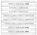
- FIG. 21 is a diagram showing a structure of multiplexed data.
- multiplexed data can be obtained by multiplexing one or more of a video stream, an audio stream, a presentation graphics stream (PG), and an interactive graphics stream.
- the video stream indicates the main video and sub-video of the movie
- the audio stream (IG) indicates the main audio portion of the movie and the sub-audio mixed with the main audio
- the presentation graphics stream indicates the subtitles of the movie.
- the main video indicates a normal video displayed on the screen
- the sub-video is a video displayed on a small screen in the main video.
- the interactive graphics stream indicates an interactive screen created by arranging GUI components on the screen.
- the video stream is encoded by the moving image encoding method or apparatus shown in the above embodiments, or the moving image encoding method or apparatus conforming to the conventional standards such as MPEG-2, MPEG4-AVC, and VC-1. ing.
- the audio stream is encoded by a method such as Dolby AC-3, Dolby Digital Plus, MLP, DTS, DTS-HD, or linear PCM.
- Each stream included in the multiplexed data is identified by PID. For example, 0x1011 for video streams used for movie images, 0x1100 to 0x111F for audio streams, 0x1200 to 0x121F for presentation graphics, 0x1400 to 0x141F for interactive graphics streams, 0x1B00 to 0x1B1F are assigned to video streams used for sub-pictures, and 0x1A00 to 0x1A1F are assigned to audio streams used for sub-audio mixed with the main audio.
- FIG. 22 is a diagram schematically showing how multiplexed data is multiplexed.
- a video stream ex235 composed of a plurality of video frames and an audio stream ex238 composed of a plurality of audio frames are converted into PES packet sequences ex236 and ex239, respectively, and converted into TS packets ex237 and ex240.
- the data of the presentation graphics stream ex241 and interactive graphics ex244 are converted into PES packet sequences ex242 and ex245, respectively, and further converted into TS packets ex243 and ex246.
- the multiplexed data ex247 is configured by multiplexing these TS packets into one stream.
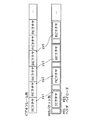
- FIG. 23 shows in more detail how the video stream is stored in the PES packet sequence.
- the first row in FIG. 23 shows a video frame sequence of the video stream.
- the second level shows a PES packet sequence.
- a plurality of Video Presentation Units in the video stream are divided into pictures, B pictures, and P pictures, and are stored in the payload of the PES packet.
- Each PES packet has a PES header, and a PTS (Presentation Time-Stamp) that is a display time of a picture and a DTS (Decoding Time-Stamp) that is a decoding time of a picture are stored in the PES header.
- PTS Presentation Time-Stamp
- DTS Decoding Time-Stamp
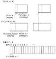
- FIG. 24 shows the format of TS packets that are finally written in the multiplexed data.
- the TS packet is a 188-byte fixed-length packet composed of a 4-byte TS header having information such as a PID for identifying a stream and a 184-byte TS payload for storing data.
- the PES packet is divided and stored in the TS payload.
- a 4-byte TP_Extra_Header is added to a TS packet, forms a 192-byte source packet, and is written in multiplexed data.
- TP_Extra_Header information such as ATS (Arrival_Time_Stamp) is described.
- ATS indicates the transfer start time of the TS packet to the PID filter of the decoder.
- Source packets are arranged in the multiplexed data as shown in the lower part of FIG. 24, and the number incremented from the head of the multiplexed data is called SPN (source packet number).
- TS packets included in the multiplexed data include PAT (Program Association Table), PMT (Program Map Table), PCR (Program Clock Reference), and the like in addition to each stream such as video / audio / caption.
- PAT indicates what the PID of the PMT used in the multiplexed data is, and the PID of the PAT itself is registered as 0.
- the PMT has the PID of each stream such as video / audio / subtitles included in the multiplexed data and the attribute information of the stream corresponding to each PID, and has various descriptors related to the multiplexed data.
- the descriptor includes copy control information for instructing permission / non-permission of copying of multiplexed data.
- the PCR corresponds to the ATS in which the PCR packet is transferred to the decoder. Contains STC time information.
- FIG. 25 is a diagram for explaining the data structure of the PMT in detail.
- a PMT header describing the length of data included in the PMT is arranged at the head of the PMT.
- a plurality of descriptors related to multiplexed data are arranged.
- the copy control information and the like are described as descriptors.
- a plurality of pieces of stream information regarding each stream included in the multiplexed data are arranged.
- the stream information includes a stream descriptor in which a stream type, a stream PID, and stream attribute information (frame rate, aspect ratio, etc.) are described to identify a compression codec of the stream.
- the multiplexed data is recorded together with the multiplexed data information file.
- the multiplexed data information file is management information of multiplexed data, has a one-to-one correspondence with the multiplexed data, and includes multiplexed data information, stream attribute information, and an entry map.
- the multiplexed data information includes a system rate, a reproduction start time, and a reproduction end time as shown in FIG.
- the system rate indicates a maximum transfer rate of multiplexed data to a PID filter of a system target decoder described later.
- the ATS interval included in the multiplexed data is set to be equal to or less than the system rate.
- the playback start time is the PTS of the first video frame of the multiplexed data
- the playback end time is set by adding the playback interval for one frame to the PTS of the video frame at the end of the multiplexed data.
- attribute information about each stream included in the multiplexed data is registered for each PID.
- the attribute information has different information for each video stream, audio stream, presentation graphics stream, and interactive graphics stream.
- the video stream attribute information includes the compression codec used to compress the video stream, the resolution of the individual picture data constituting the video stream, the aspect ratio, and the frame rate. It has information such as how much it is.
- the audio stream attribute information includes the compression codec used to compress the audio stream, the number of channels included in the audio stream, the language supported, and the sampling frequency. With information. These pieces of information are used for initialization of the decoder before the player reproduces it.
- the stream type included in the PMT is used.
- video stream attribute information included in the multiplexed data information is used.
- the video encoding shown in each of the above embodiments for the stream type or video stream attribute information included in the PMT.
- FIG. 28 shows the steps of the moving picture decoding method according to the present embodiment.
- step exS100 the stream type included in the PMT or the video stream attribute information included in the multiplexed data information is acquired from the multiplexed data.
- step exS101 it is determined whether or not the stream type or the video stream attribute information indicates multiplexed data generated by the moving picture encoding method or apparatus described in the above embodiments. To do.
- step exS102 each of the above embodiments.
- Decoding is performed by the moving picture decoding method shown in the form.
- the conventional information Decoding is performed by a moving image decoding method compliant with the standard.
- FIG. 29 shows a configuration of an LSI ex500 that is made into one chip.
- the LSI ex500 includes elements ex501, ex502, ex503, ex504, ex505, ex506, ex507, ex508, and ex509 described below, and each element is connected via a bus ex510.
- the power supply circuit unit ex505 starts up to an operable state by supplying power to each unit when the power supply is in an on state.
- the LSI ex500 uses the AV I / O ex509 to perform the microphone ex117 and the camera ex113 based on the control of the control unit ex501 including the CPU ex502, the memory controller ex503, the stream controller ex504, the drive frequency control unit ex512, and the like.
- the AV signal is input from the The input AV signal is temporarily stored in an external memory ex511 such as SDRAM.
- the accumulated data is divided into a plurality of times as appropriate according to the processing amount and the processing speed and sent to the signal processing unit ex507, and the signal processing unit ex507 encodes an audio signal and / or video. Signal encoding is performed.
- the encoding process of the video signal is the encoding process described in the above embodiments.
- the signal processing unit ex507 further performs processing such as multiplexing the encoded audio data and the encoded video data according to circumstances, and outputs the result from the stream I / Oex 506 to the outside.
- the output multiplexed data is transmitted to the base station ex107 or written to the recording medium ex215. It should be noted that data should be temporarily stored in the buffer ex508 so as to be synchronized when multiplexing.
- the memory ex511 has been described as an external configuration of the LSI ex500.
- a configuration included in the LSI ex500 may be used.
- the number of buffers ex508 is not limited to one, and a plurality of buffers may be provided.
- the LSI ex500 may be made into one chip or a plurality of chips.
- control unit ex501 includes the CPU ex502, the memory controller ex503, the stream controller ex504, the drive frequency control unit ex512, and the like, but the configuration of the control unit ex501 is not limited to this configuration.
- the signal processing unit ex507 may further include a CPU.
- the CPU ex502 may be configured to include a signal processing unit ex507 or, for example, an audio signal processing unit that is a part of the signal processing unit ex507.
- the control unit ex501 is configured to include a signal processing unit ex507 or a CPU ex502 having a part thereof.
- LSI LSI
- IC system LSI
- super LSI ultra LSI depending on the degree of integration
- the method of circuit integration is not limited to LSI, and implementation with a dedicated circuit or a general-purpose processor is also possible.
- An FPGA Field Programmable Gate Array
- a reconfigurable processor that can reconfigure the connection and setting of circuit cells inside the LSI may be used.
- FIG. 30 shows a configuration ex800 in the present embodiment.
- the drive frequency switching unit ex803 sets the drive frequency high when the video data is generated by the moving image encoding method or apparatus described in the above embodiments.
- the decoding processing unit ex801 that executes the moving picture decoding method described in each of the above embodiments is instructed to decode the video data.
- the video data is video data compliant with the conventional standard, compared to the case where the video data is generated by the moving picture encoding method or apparatus shown in the above embodiments, Set the drive frequency low. Then, it instructs the decoding processing unit ex802 compliant with the conventional standard to decode the video data.
- the drive frequency switching unit ex803 includes the CPU ex502 and the drive frequency control unit ex512 of FIG.
- the decoding processing unit ex801 that executes the moving picture decoding method shown in each of the above embodiments and the decoding processing unit ex802 that complies with the conventional standard correspond to the signal processing unit ex507 in FIG.
- the CPU ex502 identifies which standard the video data conforms to.
- the drive frequency control unit ex512 sets the drive frequency.
- the signal processing unit ex507 decodes the video data.
- the identification of the video data for example, it is conceivable to use the identification information described in the third embodiment.
- the identification information is not limited to that described in Embodiment 3, and any information that can identify which standard the video data conforms to may be used. For example, it is possible to identify which standard the video data conforms to based on an external signal that identifies whether the video data is used for a television or a disk. In some cases, identification may be performed based on such an external signal. In addition, the selection of the driving frequency in the CPU ex502 may be performed based on, for example, a lookup table in which video data standards and driving frequencies are associated with each other as shown in FIG. The look-up table is stored in the buffer ex508 or the internal memory of the LSI, and the CPU ex502 can select the drive frequency by referring to this look-up table.
- FIG. 31 shows steps for executing the method of the present embodiment.
- the signal processing unit ex507 acquires identification information from the multiplexed data.
- the CPU ex502 identifies whether the video data is generated by the encoding method or apparatus described in each of the above embodiments based on the identification information.
- the CPU ex502 sends a signal for setting the drive frequency high to the drive frequency control unit ex512. Then, the drive frequency control unit ex512 sets a high drive frequency.
- step exS203 the CPU ex502 drives a signal for setting the drive frequency low. This is sent to the frequency control unit ex512. Then, in the drive frequency control unit ex512, the drive frequency is set to be lower than that in the case where the video data is generated by the encoding method or apparatus described in the above embodiments.
- the power saving effect can be further enhanced by changing the voltage applied to the LSI ex500 or the device including the LSI ex500 in conjunction with the switching of the driving frequency.
- the drive frequency is set to be low, it is conceivable that the voltage applied to the LSI ex500 or the device including the LSI ex500 is set low as compared with the case where the drive frequency is set high.
- the setting method of the driving frequency may be set to a high driving frequency when the processing amount at the time of decoding is large, and to a low driving frequency when the processing amount at the time of decoding is small. It is not limited to the method.
- the amount of processing for decoding video data compliant with the MPEG4-AVC standard is larger than the amount of processing for decoding video data generated by the moving picture encoding method or apparatus described in the above embodiments. It is conceivable that the setting of the driving frequency is reversed to that in the case described above.
- the method for setting the drive frequency is not limited to the configuration in which the drive frequency is lowered.
- the voltage applied to the LSI ex500 or the apparatus including the LSI ex500 is set high.
- the video data conforms to the conventional standards such as MPEG-2, MPEG4-AVC, VC-1, etc.
- the identification information indicates that the video data is generated by the moving image encoding method or apparatus described in each of the above embodiments, the driving of the CPU ex502 is stopped.
- the CPU ex502 is temporarily stopped because there is enough processing. Is also possible. Even when the identification information indicates that the video data is generated by the moving image encoding method or apparatus described in each of the above embodiments, if there is enough processing, the CPU ex502 is temporarily driven. It can also be stopped. In this case, it is conceivable to set the stop time shorter than in the case where the video data conforms to the conventional standards such as MPEG-2, MPEG4-AVC, and VC-1.
- a plurality of video data that conforms to different standards may be input to the above-described devices and systems such as a television and a mobile phone.
- the signal processing unit ex507 of the LSI ex500 needs to support a plurality of standards in order to be able to decode even when a plurality of video data complying with different standards is input.
- the signal processing unit ex507 corresponding to each standard is used individually, there is a problem that the circuit scale of the LSI ex500 increases and the cost increases.
- a decoding processing unit for executing the moving picture decoding method shown in each of the above embodiments and a decoding conforming to a standard such as MPEG-2, MPEG4-AVC, or VC-1
- the processing unit is partly shared.
- An example of this configuration is shown as ex900 in FIG. 33A.
- the moving picture decoding method shown in each of the above embodiments and the moving picture decoding method compliant with the MPEG4-AVC standard are processed in processes such as entropy coding, inverse quantization, deblocking filter, and motion compensation. Some contents are common.
- the decoding processing unit ex902 corresponding to the MPEG4-AVC standard is shared, and for other processing contents unique to the present invention that do not correspond to the MPEG4-AVC standard, the dedicated decoding processing unit ex901 is used.
- Configuration is conceivable.
- the present invention is characterized by filter processing (deblocking filter), for example, dedicated decoding processing unit ex901 is used for filter processing (deblocking filter), and other entropy codes are used. It is conceivable to share the decoding processing unit for any of the quantization, inverse quantization, motion compensation, or all the processes.
- the decoding processing unit for executing the moving picture decoding method described in each of the above embodiments is shared, and the processing content specific to the MPEG4-AVC standard As for, a configuration using a dedicated decoding processing unit may be used.
- ex1000 in FIG. 33B shows another example in which processing is partially shared.
- a dedicated decoding processing unit ex1001 corresponding to processing content specific to the present invention
- a dedicated decoding processing unit ex1002 corresponding to processing content specific to other conventional standards
- a moving picture decoding method of the present invention A common decoding processing unit ex1003 corresponding to processing contents common to other conventional video decoding methods is used.
- the dedicated decoding processing units ex1001 and ex1002 are not necessarily specialized in the processing content specific to the present invention or other conventional standards, and may be capable of executing other general-purpose processing.
- the configuration of the present embodiment can be implemented by LSI ex500.
- the circuit scale of the LSI is reduced, and the cost is reduced. It is possible to reduce.
- the present invention can be applied to a filter method, a video encoding device, and a video decoding device.
- the present invention can be used for high-resolution information display devices or imaging devices such as televisions, digital video recorders, car navigation systems, mobile phones, digital cameras, and digital video cameras.
Landscapes
- Engineering & Computer Science (AREA)
- Multimedia (AREA)
- Signal Processing (AREA)
- Compression Or Coding Systems Of Tv Signals (AREA)
Priority Applications (17)
| Application Number | Priority Date | Filing Date | Title |
|---|---|---|---|
| CN201510828833.1A CN105245904B (zh) | 2011-02-22 | 2012-02-21 | 图像编码解码装置 |
| MX2013000093A MX2013000093A (es) | 2011-02-22 | 2012-02-21 | Metodo de filtro, dispositivo de codificacion de imagen dinamica, dispositivo de decodificacion de imagen dinamica y dispositivo de codificacion y decodificacion de imagen dinamica. |
| KR1020207013443A KR102194079B1 (ko) | 2011-02-22 | 2012-02-21 | 필터 방법, 동화상 부호화 장치, 동화상 복호 장치 및 동화상 부호화 복호 장치 |
| AU2012221587A AU2012221587B9 (en) | 2011-02-22 | 2012-02-21 | Filtering method, moving picture coding apparatus, moving picture decoding apparatus, and moving picture coding and decoding apparatus |
| KR1020197004768A KR102030977B1 (ko) | 2011-02-22 | 2012-02-21 | 필터 방법, 동화상 부호화 장치, 동화상 복호 장치 및 동화상 부호화 복호 장치 |
| KR1020137001913A KR101954461B1 (ko) | 2011-02-22 | 2012-02-21 | 필터 방법, 동화상 부호화 장치, 동화상 복호 장치 및 동화상 부호화 복호 장치 |
| BR112012021600-7A BR112012021600B1 (pt) | 2011-02-22 | 2012-02-21 | método de filtragem de desbloqueio para filtrar uma pluralidade de blocos incluídos em uma imagem, método e aparelho de codificação para codificar uma imagem |
| LTEP12749678.4T LT2680583T (lt) | 2011-02-22 | 2012-02-21 | Filtravimo būdas, dinamiškas vaizdo kodavimo įrenginys, dinamiškas vaizdo dekodavimo įrenginys ir dinamiškas vaizdo kodavimo/dekodavimo įrenginys |
| ES12749678.4T ES2669978T3 (es) | 2011-02-22 | 2012-02-21 | Método de filtrado, dispositivo de codificación de imágenes dinámicas, dispositivo de decodificación de imágenes dinámicas y dispositivo de codificación/decodificación de imágenes dinámicas |
| JP2012533164A JP5342069B2 (ja) | 2011-02-22 | 2012-02-21 | フィルタ方法、画像符号化方法、画像処理システム及び画像符号化装置 |
| EP12749678.4A EP2680583B1 (en) | 2011-02-22 | 2012-02-21 | Filter method, dynamic image encoding device, dynamic image decoding device, and dynamic image encoding/decoding device |
| PL12749678T PL2680583T3 (pl) | 2011-02-22 | 2012-02-21 | Sposób filtrowania, dynamiczne urządzenie kodujące obraz, dynamiczne urządzenie dekodujące obraz i dynamiczne urządzenie kodujące/dekodujące obraz |
| CA2801215A CA2801215C (en) | 2011-02-22 | 2012-02-21 | Filtering method, moving picture coding apparatus, moving picture decoding apparatus, and moving picture coding and decoding apparatus |
| KR1020207036109A KR102215469B1 (ko) | 2011-02-22 | 2012-02-21 | 필터 방법, 동화상 부호화 장치, 동화상 복호 장치 및 동화상 부호화 복호 장치 |
| KR1020197028120A KR102112241B1 (ko) | 2011-02-22 | 2012-02-21 | 필터 방법, 동화상 부호화 장치, 동화상 복호 장치 및 동화상 부호화 복호 장치 |
| CN201280000774.3A CN102907097B (zh) | 2011-02-22 | 2012-02-21 | 滤波方法、动态图像编码装置、动态图像解码装置和动态图像编码解码装置 |
| AU2017203193A AU2017203193B2 (en) | 2011-02-22 | 2017-05-12 | Filtering method, moving picture coding apparatus, moving picture decoding apparatus, and moving picture coding and decoding apparatus |
Applications Claiming Priority (2)
| Application Number | Priority Date | Filing Date | Title |
|---|---|---|---|
| US201161445115P | 2011-02-22 | 2011-02-22 | |
| US61/445,115 | 2011-02-22 |
Publications (1)
| Publication Number | Publication Date |
|---|---|
| WO2012114724A1 true WO2012114724A1 (ja) | 2012-08-30 |
Family
ID=46652730
Family Applications (1)
| Application Number | Title | Priority Date | Filing Date |
|---|---|---|---|
| PCT/JP2012/001167 WO2012114724A1 (ja) | 2011-02-22 | 2012-02-21 | フィルタ方法、動画像符号化装置、動画像復号装置及び動画像符号化復号装置 |
Country Status (15)
| Country | Link |
|---|---|
| US (5) | US9826230B2 (es) |
| EP (1) | EP2680583B1 (es) |
| JP (4) | JP5342069B2 (es) |
| KR (5) | KR102030977B1 (es) |
| CN (3) | CN105245904B (es) |
| AU (2) | AU2012221587B9 (es) |
| BR (1) | BR112012021600B1 (es) |
| CA (2) | CA2801215C (es) |
| ES (1) | ES2669978T3 (es) |
| HU (1) | HUE038308T2 (es) |
| LT (1) | LT2680583T (es) |
| MX (1) | MX2013000093A (es) |
| PL (1) | PL2680583T3 (es) |
| TW (3) | TWI574555B (es) |
| WO (1) | WO2012114724A1 (es) |
Cited By (5)
| Publication number | Priority date | Publication date | Assignee | Title |
|---|---|---|---|---|
| WO2013011659A1 (ja) * | 2011-07-19 | 2013-01-24 | パナソニック株式会社 | フィルタ方法、動画像復号方法、動画像符号化方法、動画像復号装置、動画像符号化装置及び動画像符号化復号装置 |
| JP2014003660A (ja) * | 2011-02-22 | 2014-01-09 | Panasonic Corp | 画像復号方法及び画像復号装置 |
| US8660375B2 (en) | 2011-02-22 | 2014-02-25 | Panasonic Corporation | Image coding method, image decoding method, image coding apparatus, image decoding apparatus, and image coding and decoding apparatus |
| EP2805493A1 (en) * | 2012-01-17 | 2014-11-26 | Futurewei Technologies, Inc. | In-loop filtering for lossless coding mode in high efficiency video coding |
| JP2018050340A (ja) * | 2014-05-29 | 2018-03-29 | キヤノン株式会社 | 映像サンプルのブロックをデブロックする方法、装置、及び、システム |
Families Citing this family (8)
| Publication number | Priority date | Publication date | Assignee | Title |
|---|---|---|---|---|
| KR20110123651A (ko) * | 2010-05-07 | 2011-11-15 | 한국전자통신연구원 | 생략 부호화를 이용한 영상 부호화 및 복호화 장치 및 그 방법 |
| US20120230423A1 (en) * | 2011-03-10 | 2012-09-13 | Esenlik Semih | Line memory reduction for video coding and decoding |
| CN107396129B (zh) * | 2011-03-30 | 2020-05-05 | Lg 电子株式会社 | 环路滤波方法及其设备 |
| GB2503658B (en) * | 2012-06-29 | 2015-07-01 | Canon Kk | Method and device for encoding and decoding data in a video encoder and a video decoder |
| JP6413381B2 (ja) * | 2014-06-19 | 2018-10-31 | 日油株式会社 | ゲル状栄養組成物 |
| TW201842768A (zh) * | 2017-04-06 | 2018-12-01 | 美商松下電器(美國)知識產權公司 | 編碼裝置、解碼裝置、編碼方法及解碼方法 |
| TWI774750B (zh) * | 2017-04-06 | 2022-08-21 | 美商松下電器(美國)知識產權公司 | 編碼裝置、解碼裝置、編碼方法及解碼方法 |
| WO2020218793A1 (ko) * | 2019-04-20 | 2020-10-29 | 엘지전자 주식회사 | Bdpcm에 기반한 영상 코딩 방법 및 그 장치 |
Citations (1)
| Publication number | Priority date | Publication date | Assignee | Title |
|---|---|---|---|---|
| WO2012008130A1 (ja) * | 2010-07-13 | 2012-01-19 | 日本電気株式会社 | 映像符号化装置、映像復号装置、映像符号化方法、映像復号方法及びプログラム |
Family Cites Families (90)
| Publication number | Priority date | Publication date | Assignee | Title |
|---|---|---|---|---|
| WO1983000570A1 (en) | 1981-07-30 | 1983-02-17 | Müller, Hans | Method for rastering half-tone images |
| US5178418A (en) | 1991-06-25 | 1993-01-12 | Canadian Bank Note Co., Ltd. | Latent images comprising phase shifted micro printing |
| AU699124B2 (en) | 1994-11-01 | 1998-11-26 | De La Rue Giori S.A. | Method of generating a security design with the aid of electronic means |
| US6104812A (en) | 1998-01-12 | 2000-08-15 | Juratrade, Limited | Anti-counterfeiting method and apparatus using digital screening |
| US6377706B1 (en) | 1998-05-12 | 2002-04-23 | Xerox Corporation | Compression framework incorporating decoding commands |
| US6473516B1 (en) | 1998-05-22 | 2002-10-29 | Asa Systems, Inc. | Large capacity steganography |
| WO2001048944A1 (en) | 1999-12-23 | 2001-07-05 | Institut National De La Recherche Scientifique | Interference suppression in cdma systems |
| US6615890B1 (en) * | 2000-06-09 | 2003-09-09 | Venture Tape Corp. | Tape applicator for glazing applications |
| US6692030B1 (en) | 2000-07-21 | 2004-02-17 | Verify First Technologies, Inc. | Security document with nano-pattern |
| DE10044403A1 (de) | 2000-09-08 | 2002-03-21 | Giesecke & Devrient Gmbh | Datenträger mit Stichtiefdruckbild und Verfahren zur Umsetzung von Bildmotiven in Linienstrukturen sowie in eine Stichtiefdruckplatte |
| US6931062B2 (en) * | 2001-04-11 | 2005-08-16 | Koninklijke Philips Electronics N.V. | Decoding system and method for proper interpolation for motion compensation |
| KR100929078B1 (ko) | 2001-11-29 | 2009-11-30 | 파나소닉 주식회사 | 코딩 왜곡 제거 방법 |
| EP1452039B1 (en) | 2001-11-29 | 2008-12-31 | Panasonic Corporation | Coding distortion removal method and video encoding and decoding methods |
| JP4130783B2 (ja) | 2002-04-23 | 2008-08-06 | 松下電器産業株式会社 | 動きベクトル符号化方法および動きベクトル復号化方法 |
| ES2730953T3 (es) | 2002-04-26 | 2019-11-13 | Ntt Docomo Inc | Método de decodificación de señal, dispositivo de decodificación de señal, y programa de decodificación de señal |
| JP4144258B2 (ja) | 2002-05-29 | 2008-09-03 | ソニー株式会社 | 画像出力装置及び画像出力方法 |
| CA2492004C (en) | 2002-07-09 | 2009-02-03 | Bnc Ip Switzerland Gmbh | System and method for providing secure identification solutions |
| CA2448064C (en) | 2002-07-11 | 2012-08-07 | Matsushita Electric Industrial Co., Ltd. | Filtering strength determination method, moving picture coding method and moving picture decoding method |
| MXPA05003984A (es) | 2002-10-15 | 2005-06-22 | Digimarc Corp | Documento de identificacion y metodos relacionados. |
| US6922492B2 (en) | 2002-12-27 | 2005-07-26 | Motorola, Inc. | Video deblocking method and apparatus |
| US8223393B2 (en) | 2003-03-31 | 2012-07-17 | Eastman Kodak Company | Post rip image rendering for microprinting |
| WO2004104779A2 (en) | 2003-05-16 | 2004-12-02 | Digimarc Corporation | Identification document usable with d2t2 printing |
| US7755620B2 (en) * | 2003-05-20 | 2010-07-13 | Interlego Ag | Method and system for manipulating a digital representation of a three-dimensional object |
| CA2532296A1 (en) | 2003-07-17 | 2005-02-03 | Digimarc Corporation | Uniquely linking security elements in identification documents |
| CN100493205C (zh) * | 2003-08-19 | 2009-05-27 | 松下电器产业株式会社 | 动态图像编码方法及动态图像解码方法 |
| US7457362B2 (en) | 2003-10-24 | 2008-11-25 | Texas Instruments Incorporated | Loop deblock filtering of block coded video in a very long instruction word processor |
| KR101000926B1 (ko) | 2004-03-11 | 2010-12-13 | 삼성전자주식회사 | 영상의 불연속성을 제거하기 위한 필터 및 필터링 방법 |
| ATE555476T1 (de) | 2004-04-28 | 2012-05-15 | Panasonic Corp | Stream-erzeugungsvorrichtung für bewegliche bilder, kodierungsvorrichtung für bewegliche bilder, multiplex-vorrichtung für bewegliche bilder und decodierungsvorrichtung für bewegliche bilder |
| US20050243914A1 (en) | 2004-04-29 | 2005-11-03 | Do-Kyoung Kwon | Adaptive de-blocking filtering apparatus and method for mpeg video decoder |
| US8085846B2 (en) | 2004-08-24 | 2011-12-27 | Thomson Licensing | Method and apparatus for decoding hybrid intra-inter coded blocks |
| US7630902B2 (en) * | 2004-09-17 | 2009-12-08 | Digital Rise Technology Co., Ltd. | Apparatus and methods for digital audio coding using codebook application ranges |
| US7450121B2 (en) | 2004-10-19 | 2008-11-11 | Canon Kabushiki Kaisha | Dynamic bit depth rendering |
| US20060126744A1 (en) * | 2004-12-10 | 2006-06-15 | Liang Peng | Two pass architecture for H.264 CABAC decoding process |
| KR100679035B1 (ko) * | 2005-01-04 | 2007-02-06 | 삼성전자주식회사 | 인트라 bl 모드를 고려한 디블록 필터링 방법, 및 상기방법을 이용하는 다 계층 비디오 인코더/디코더 |
| JP4148228B2 (ja) | 2005-02-10 | 2008-09-10 | ソニー株式会社 | 画像記録装置、画像再生制御装置、画像記録再生制御装置、これらの装置の処理方法およびその方法をコンピュータに実行させるプログラム |
| JP4784188B2 (ja) | 2005-07-25 | 2011-10-05 | ソニー株式会社 | 画像処理装置、画像処理方法およびプログラム |
| US8625914B2 (en) | 2013-02-04 | 2014-01-07 | Sony Corporation | Image processing system, image processing method and program |
| WO2007116551A1 (ja) | 2006-03-30 | 2007-10-18 | Kabushiki Kaisha Toshiba | 画像符号化装置及び画像符号化方法並びに画像復号化装置及び画像復号化方法 |
| JP5017555B2 (ja) | 2006-04-10 | 2012-09-05 | 株式会社メガチップス | 画像符号化装置及び画像復号化装置 |
| EP1844929A1 (fr) | 2006-04-13 | 2007-10-17 | Kba-Giori S.A. | Procédé de génération de motifs représentant une image en demi-teintes |
| US7965422B2 (en) | 2006-04-28 | 2011-06-21 | Xerox Corporation | Super resolution encoded microprinting through postscript |
| JP4584871B2 (ja) | 2006-06-09 | 2010-11-24 | パナソニック株式会社 | 画像符号化記録装置および画像符号化記録方法 |
| US8036270B2 (en) * | 2006-07-27 | 2011-10-11 | Sharp Laboratories Of America, Inc. | Intra-frame flicker reduction in video coding |
| JP2008042497A (ja) | 2006-08-04 | 2008-02-21 | Seiko Epson Corp | デコード装置、情報再生装置及び電子機器 |
| JP5093877B2 (ja) | 2006-09-29 | 2012-12-12 | 株式会社ユニバーサルエンターテインメント | 紙葉識別装置 |
| KR100827106B1 (ko) * | 2006-10-20 | 2008-05-02 | 삼성전자주식회사 | 디블록킹 필터에서의 필터 조건 영역 판별을 위한 장치 및방법 |
| JP5039142B2 (ja) | 2006-10-25 | 2012-10-03 | フラウンホーファー−ゲゼルシャフト・ツール・フェルデルング・デル・アンゲヴァンテン・フォルシュング・アインゲトラーゲネル・フェライン | 品質スケーラブルな符号化方法 |
| CN101193305B (zh) | 2006-11-21 | 2010-05-12 | 安凯(广州)微电子技术有限公司 | 用于视频编解码芯片中帧内预测的数据存储和交换方法 |
| KR100837410B1 (ko) | 2006-11-30 | 2008-06-12 | 삼성전자주식회사 | 주관적인 무손실 이미지 데이터 압축 방법 및 장치 |
| CN101290774B (zh) * | 2007-01-31 | 2011-09-07 | 广州广晟数码技术有限公司 | 音频编码和解码系统 |
| US8767834B2 (en) * | 2007-03-09 | 2014-07-01 | Sharp Laboratories Of America, Inc. | Methods and systems for scalable-to-non-scalable bit-stream rewriting |
| TW200845723A (en) | 2007-04-23 | 2008-11-16 | Thomson Licensing | Method and apparatus for encoding video data, method and apparatus for decoding encoded video data and encoded video signal |
| KR101376666B1 (ko) | 2007-06-27 | 2014-03-21 | 톰슨 라이센싱 | 이미지 품질 강화 |
| US8577687B2 (en) | 2007-07-06 | 2013-11-05 | France Telecom | Hierarchical coding of digital audio signals |
| JP2009017505A (ja) | 2007-07-09 | 2009-01-22 | Toshiba Corp | 画像圧縮装置、画像伸張装置及び画像処理装置 |
| US20090315319A1 (en) | 2007-07-17 | 2009-12-24 | Jimmy Kendrick | Security documents and methods of deterring counterfeiting |
| US20090021000A1 (en) | 2007-07-17 | 2009-01-22 | Mccartney Larry G | Security documents and methods of deterring counterfeiting |
| US20090020999A1 (en) | 2007-07-17 | 2009-01-22 | Jimmy Kendrick | Security documents and methods of deterring counterfeiting |
| US9521433B2 (en) | 2007-09-06 | 2016-12-13 | Nec Corporation | Video encoding device, video decoding device, video encoding method, video decoding method, video encoding or decoding program |
| CN101389016B (zh) | 2007-09-13 | 2010-10-20 | 华为技术有限公司 | 获得块边界强度和去除块效应的方法和装置 |
| BRPI0818444A2 (pt) * | 2007-10-12 | 2016-10-11 | Qualcomm Inc | codificação adaptativa de informação de cabeçalho de bloco de vídeo |
| JP5526032B2 (ja) * | 2007-10-16 | 2014-06-18 | トムソン ライセンシング | ジオメトリック分割されたスーパブロックをビデオ符号化およびビデオ復号する方法および装置 |
| US8477847B2 (en) | 2007-12-17 | 2013-07-02 | Vixs Systems, Inc. | Motion compensation module with fast intra pulse code modulation mode decisions and methods for use therewith |
| US9225996B2 (en) | 2007-12-19 | 2015-12-29 | Vixs Systems, Inc. | Motion refinement engine with flexible direction processing and methods for use therewith |
| US8743972B2 (en) | 2007-12-20 | 2014-06-03 | Vixs Systems, Inc. | Coding adaptive deblocking filter and method for use therewith |
| EP2232875A2 (en) | 2008-01-11 | 2010-09-29 | Thomson Licensing | Video and depth coding |
| JP5593596B2 (ja) | 2008-02-04 | 2014-09-24 | ソニー株式会社 | 映像信号送信装置および映像信号送信方法 |
| US8542730B2 (en) * | 2008-02-22 | 2013-09-24 | Qualcomm, Incorporated | Fast macroblock delta QP decision |
| US9788018B2 (en) * | 2008-06-30 | 2017-10-10 | Microsoft Technology Licensing, Llc | Error concealment techniques in video decoding |
| TWI386068B (zh) | 2008-10-22 | 2013-02-11 | Nippon Telegraph & Telephone | 解塊處理方法、解塊處理裝置、解塊處理程式及記錄該程式之可由電腦讀取之記錄媒體 |
| TW201028018A (en) * | 2009-01-07 | 2010-07-16 | Ind Tech Res Inst | Encoder, decoder, encoding method and decoding method |
| JP5126096B2 (ja) | 2009-02-05 | 2013-01-23 | 日本電気株式会社 | 画像符号化処理方法、画像符号化処理装置、画像符号化プログラム |
| WO2010125606A1 (en) | 2009-04-29 | 2010-11-04 | Aspa-Japan Co., Ltd. | Method for image data compression and compression system of image data |
| TWI400955B (zh) | 2009-07-20 | 2013-07-01 | Mstar Semiconductor Inc | 一種去區塊裝置及方法 |
| CN101621692B (zh) | 2009-07-27 | 2011-04-20 | 宁波大学 | 一种基于预测模式的h.264/avc视频信息隐藏方法 |
| WO2011037933A1 (en) | 2009-09-22 | 2011-03-31 | Panasonic Corporation | Image coding apparatus, image decoding apparatus, image coding method, and image decoding method |
| WO2012062505A1 (de) | 2010-11-08 | 2012-05-18 | U-Nica Technology Ag | Verfahren und vorrichtung zur erzeugung von farbbildern mit einem uv-laser auf pigmentierten substraten und dadurch hergestellte produkte |
| ES2688086T3 (es) | 2010-11-26 | 2018-10-30 | Nec Corporation | Dispositivo de descodificación de video, método de descodificación de video y programa |
| KR102295680B1 (ko) | 2010-12-08 | 2021-08-31 | 엘지전자 주식회사 | 인트라 예측 방법과 이를 이용한 부호화 장치 및 복호화 장치 |
| CN102025997A (zh) | 2010-12-22 | 2011-04-20 | 中兴通讯股份有限公司 | 隐藏信息的方法和装置、提取隐藏信息的方法和装置 |
| US9137539B2 (en) | 2010-12-22 | 2015-09-15 | Panasonic Corporation | Image coding apparatus, image decoding apparatus, image coding method, and image decoding method |
| JP5850214B2 (ja) | 2011-01-11 | 2016-02-03 | ソニー株式会社 | 画像処理装置および方法、プログラム、並びに記録媒体 |
| WO2012114725A1 (ja) | 2011-02-22 | 2012-08-30 | パナソニック株式会社 | 画像符号化方法、画像復号化方法、画像符号化装置、画像復号化装置および画像符号化復号化装置 |
| KR102030977B1 (ko) | 2011-02-22 | 2019-10-10 | 타지반 투 엘엘씨 | 필터 방법, 동화상 부호화 장치, 동화상 복호 장치 및 동화상 부호화 복호 장치 |
| US9652814B2 (en) | 2011-03-29 | 2017-05-16 | Jura Trade, Limited | Method and apparatus for generating and authenticating security documents |
| CN107396129B (zh) | 2011-03-30 | 2020-05-05 | Lg 电子株式会社 | 环路滤波方法及其设备 |
| CN103563374B (zh) | 2011-05-27 | 2017-02-08 | 索尼公司 | 图像处理设备及方法 |
| EP2713612A4 (en) | 2011-06-28 | 2014-11-26 | Samsung Electronics Co Ltd | METHOD AND APPARATUS FOR ENCODING AND DECODING IMAGE USING THE ADAPTIVE QUANTIFICATION PARAMETER DIFFERENTIAL |
| US9510020B2 (en) | 2011-10-20 | 2016-11-29 | Qualcomm Incorporated | Intra pulse code modulation (IPCM) and lossless coding mode deblocking for video coding |
| US9161046B2 (en) | 2011-10-25 | 2015-10-13 | Qualcomm Incorporated | Determining quantization parameters for deblocking filtering for video coding |
-
2012
- 2012-02-21 KR KR1020197004768A patent/KR102030977B1/ko active IP Right Grant
- 2012-02-21 MX MX2013000093A patent/MX2013000093A/es active IP Right Grant
- 2012-02-21 US US13/400,896 patent/US9826230B2/en active Active
- 2012-02-21 PL PL12749678T patent/PL2680583T3/pl unknown
- 2012-02-21 CN CN201510828833.1A patent/CN105245904B/zh active Active
- 2012-02-21 WO PCT/JP2012/001167 patent/WO2012114724A1/ja active Application Filing
- 2012-02-21 TW TW104140790A patent/TWI574555B/zh active
- 2012-02-21 LT LTEP12749678.4T patent/LT2680583T/lt unknown
- 2012-02-21 JP JP2012533164A patent/JP5342069B2/ja active Active
- 2012-02-21 AU AU2012221587A patent/AU2012221587B9/en active Active
- 2012-02-21 ES ES12749678.4T patent/ES2669978T3/es active Active
- 2012-02-21 CN CN201280000774.3A patent/CN102907097B/zh active Active
- 2012-02-21 TW TW104140789A patent/TWI547152B/zh active
- 2012-02-21 CN CN201510828803.0A patent/CN105245903B/zh active Active
- 2012-02-21 TW TW101105646A patent/TWI562643B/zh active
- 2012-02-21 KR KR1020207013443A patent/KR102194079B1/ko active IP Right Grant
- 2012-02-21 BR BR112012021600-7A patent/BR112012021600B1/pt not_active IP Right Cessation
- 2012-02-21 CA CA2801215A patent/CA2801215C/en active Active
- 2012-02-21 KR KR1020137001913A patent/KR101954461B1/ko active IP Right Grant
- 2012-02-21 EP EP12749678.4A patent/EP2680583B1/en active Active
- 2012-02-21 KR KR1020207036109A patent/KR102215469B1/ko active IP Right Grant
- 2012-02-21 KR KR1020197028120A patent/KR102112241B1/ko active IP Right Grant
- 2012-02-21 CA CA3027092A patent/CA3027092C/en active Active
- 2012-02-21 HU HUE12749678A patent/HUE038308T2/hu unknown
-
2013
- 2013-08-08 JP JP2013165255A patent/JP5422773B2/ja active Active
- 2013-08-08 JP JP2013165128A patent/JP5843818B2/ja active Active
- 2013-09-09 JP JP2013186480A patent/JP5559918B2/ja active Active
- 2013-12-19 US US14/134,812 patent/US9729874B2/en active Active
-
2017
- 2017-05-12 AU AU2017203193A patent/AU2017203193B2/en active Active
- 2017-06-09 US US15/618,757 patent/US10015498B2/en active Active
-
2018
- 2018-04-30 US US15/966,403 patent/US10511844B2/en active Active
-
2019
- 2019-11-07 US US16/677,014 patent/US10798391B2/en active Active
Patent Citations (1)
| Publication number | Priority date | Publication date | Assignee | Title |
|---|---|---|---|---|
| WO2012008130A1 (ja) * | 2010-07-13 | 2012-01-19 | 日本電気株式会社 | 映像符号化装置、映像復号装置、映像符号化方法、映像復号方法及びプログラム |
Non-Patent Citations (2)
| Title |
|---|
| KEIICHI CHONO ET AL.: "Proposal of enhanced PCM coding in HEVC", JOINT COLLABORATIVE TEAM ON VIDEO CODING (JCT-VC) OF ITU-T SG16 WP3 AND ISO/IEC JTC1/SC29/WG11, JCTVC-E192-R2, 5TH MEETING, 16 March 2011 (2011-03-16) - 23 March 2011 (2011-03-23), GENEVA, CH, pages 1 - 12, XP030048277 * |
| KEIICHI CHONO ET AL.: "Pulse code modulation mode for HEVC", JOINT COLLABORATIVE TEAM ON VIDEO CODING (JCT-VC) OF ITU-T SG16 WP3 AND ISO/IEC JTC1/SC29/WG11, JCTVC-D044-REV1, 4TH MEETING, 20 January 2011 (2011-01-20) - 28 January 2011 (2011-01-28), DAEGU, KOREA, pages 1 - 9, XP030047361 * |
Cited By (40)
| Publication number | Priority date | Publication date | Assignee | Title |
|---|---|---|---|---|
| US9729874B2 (en) | 2011-02-22 | 2017-08-08 | Tagivan Ii Llc | Filtering method, moving picture coding apparatus, moving picture decoding apparatus, and moving picture coding and decoding apparatus |
| JP2014003660A (ja) * | 2011-02-22 | 2014-01-09 | Panasonic Corp | 画像復号方法及び画像復号装置 |
| JP2014017847A (ja) * | 2011-02-22 | 2014-01-30 | Panasonic Corp | 画像を復号する装置、システム及び画像視聴方法 |
| US10602159B2 (en) | 2011-02-22 | 2020-03-24 | Sun Patent Trust | Image coding method, image decoding method, image coding apparatus, image decoding apparatus, and image coding and decoding apparatus |
| US8660375B2 (en) | 2011-02-22 | 2014-02-25 | Panasonic Corporation | Image coding method, image decoding method, image coding apparatus, image decoding apparatus, and image coding and decoding apparatus |
| US10511844B2 (en) | 2011-02-22 | 2019-12-17 | Tagivan Ii Llc | Filtering method, moving picture coding apparatus, moving picture decoding apparatus, and moving picture coding and decoding apparatus |
| US10237562B2 (en) | 2011-02-22 | 2019-03-19 | Sun Patent Trust | Image coding method, image decoding method, image coding apparatus, image decoding apparatus, and image coding and decoding apparatus |
| US10015498B2 (en) | 2011-02-22 | 2018-07-03 | Tagivan Ii Llc | Filtering method, moving picture coding apparatus, moving picture decoding apparatus, and moving picture coding and decoding apparatus |
| US9961352B2 (en) | 2011-02-22 | 2018-05-01 | Sun Patent Trust | Image coding method, image decoding method, image coding apparatus, image decoding apparatus, and image coding and decoding apparatus |
| US8855435B2 (en) | 2011-02-22 | 2014-10-07 | Panasonic Intellectual Property Corporation Of America | Image coding method, image decoding method, image coding apparatus, image decoding apparatus, and image coding and decoding apparatus |
| US10798391B2 (en) | 2011-02-22 | 2020-10-06 | Tagivan Ii Llc | Filtering method, moving picture coding apparatus, moving picture decoding apparatus, and moving picture coding and decoding apparatus |
| US8917946B2 (en) | 2011-02-22 | 2014-12-23 | Panasonic Intellectual Property Corporation Of America | Image coding method, image decoding method, image coding apparatus, image decoding apparatus, and image coding and decoding apparatus |
| US9489749B2 (en) | 2011-02-22 | 2016-11-08 | Sun Patent Trust | Image coding method, image decoding method, image coding apparatus, image decoding apparatus, and image coding and decoding apparatus |
| US9826230B2 (en) | 2011-02-22 | 2017-11-21 | Tagivan Ii Llc | Encoding method and encoding apparatus |
| US8787467B2 (en) | 2011-07-19 | 2014-07-22 | Panasonic Corporation | Filtering method for performing deblocking filtering on a boundary between an intra pulse code modulation block and a non-intra pulse code modulation block which are adjacent to each other in an image |
| JP2014042325A (ja) * | 2011-07-19 | 2014-03-06 | Panasonic Corp | 符号化復号装置 |
| US9667968B2 (en) | 2011-07-19 | 2017-05-30 | Tagivan Ii Llc | Filtering method for performing deblocking filtering on a boundary between an intra pulse code modulation block and a non-intra pulse code modulation block which are adjacent to each other in an image |
| US9774888B2 (en) | 2011-07-19 | 2017-09-26 | Tagivan Ii Llc | Filtering method for performing deblocking filtering on a boundary between an intra pulse code modulation block and a non-intra pulse code modulation block which are adjacent to each other in an image |
| US9544585B2 (en) | 2011-07-19 | 2017-01-10 | Tagivan Ii Llc | Filtering method for performing deblocking filtering on a boundary between an intra pulse code modulation block and a non-intra pulse code modulation block which are adjacent to each other in an image |
| US9930367B2 (en) | 2011-07-19 | 2018-03-27 | Tagivan Ii Llc | Filtering method for performing deblocking filtering on a boundary between an intra pulse code modulation block and a non-intra pulse code modulation block which are adjacent to each other in an image |
| WO2013011659A1 (ja) * | 2011-07-19 | 2013-01-24 | パナソニック株式会社 | フィルタ方法、動画像復号方法、動画像符号化方法、動画像復号装置、動画像符号化装置及び動画像符号化復号装置 |
| KR102128999B1 (ko) | 2011-07-19 | 2020-07-02 | 타지반 투 엘엘씨 | 필터 방법, 복호 방법, 및 부호화 방법 |
| KR20140043734A (ko) * | 2011-07-19 | 2014-04-10 | 파나소닉 주식회사 | 필터 방법, 복호 방법, 및 부호화 방법 |
| JP2017098953A (ja) * | 2011-07-19 | 2017-06-01 | タギバン ツー エルエルシー | フィルタ方法及び画像処理システム |
| KR102129001B1 (ko) | 2011-07-19 | 2020-07-02 | 타지반 투 엘엘씨 | 필터 방법, 복호 방법, 및 부호화 방법 |
| KR102129000B1 (ko) | 2011-07-19 | 2020-07-02 | 타지반 투 엘엘씨 | 필터 방법, 복호 방법, 및 부호화 방법 |
| KR102023210B1 (ko) | 2011-07-19 | 2019-09-19 | 타지반 투 엘엘씨 | 필터 방법, 복호 방법, 및 부호화 방법 |
| JP2014042326A (ja) * | 2011-07-19 | 2014-03-06 | Panasonic Corp | 復号方法及び復号装置 |
| KR102064408B1 (ko) | 2011-07-19 | 2020-01-09 | 타지반 투 엘엘씨 | 필터 방법, 복호 방법, 및 부호화 방법 |
| KR20200004464A (ko) * | 2011-07-19 | 2020-01-13 | 타지반 투 엘엘씨 | 필터 방법, 복호 방법, 및 부호화 방법 |
| KR20200004465A (ko) * | 2011-07-19 | 2020-01-13 | 타지반 투 엘엘씨 | 필터 방법, 복호 방법, 및 부호화 방법 |
| KR20200004916A (ko) * | 2011-07-19 | 2020-01-14 | 타지반 투 엘엘씨 | 필터 방법, 복호 방법, 및 부호화 방법 |
| JP2014030258A (ja) * | 2011-07-19 | 2014-02-13 | Panasonic Corp | 符号化方法及び符号化装置 |
| EP2805493A1 (en) * | 2012-01-17 | 2014-11-26 | Futurewei Technologies, Inc. | In-loop filtering for lossless coding mode in high efficiency video coding |
| US10298961B2 (en) | 2014-05-29 | 2019-05-21 | Canon Kabushiki Kaisha | Method, apparatus and system for de-blocking a block of video samples |
| JP2019071632A (ja) * | 2014-05-29 | 2019-05-09 | キヤノン株式会社 | 映像サンプルのブロックをデブロックする方法 |
| JP2020108160A (ja) * | 2014-05-29 | 2020-07-09 | キヤノン株式会社 | 映像サンプルのブロックをデブロックする方法 |
| JP2018050340A (ja) * | 2014-05-29 | 2018-03-29 | キヤノン株式会社 | 映像サンプルのブロックをデブロックする方法、装置、及び、システム |
| JP2021108475A (ja) * | 2014-05-29 | 2021-07-29 | キヤノン株式会社 | 映像サンプルのブロックをデブロックする方法 |
| JP7104827B2 (ja) | 2014-05-29 | 2022-07-21 | キヤノン株式会社 | 映像サンプルのブロックをデブロックする方法 |
Also Published As
Similar Documents
| Publication | Publication Date | Title |
|---|---|---|
| JP6216021B2 (ja) | フィルタ方法及び画像処理システム | |
| AU2017203193B2 (en) | Filtering method, moving picture coding apparatus, moving picture decoding apparatus, and moving picture coding and decoding apparatus | |
| CA2876567C (en) | Image coding and decoding of slice boundaries wherein loop filtering of top and left slice boundaries is controlled by a boundary control flag | |
| WO2013073184A1 (ja) | 画像符号化方法、画像復号方法、画像符号化装置、画像復号装置、および画像符号化復号装置 |
Legal Events
| Date | Code | Title | Description |
|---|---|---|---|
| WWE | Wipo information: entry into national phase |
Ref document number: 201280000774.3 Country of ref document: CN |
|
| WWE | Wipo information: entry into national phase |
Ref document number: 2012533164 Country of ref document: JP |
|
| WWE | Wipo information: entry into national phase |
Ref document number: 7418/CHENP/2012 Country of ref document: IN |
|
| 121 | Ep: the epo has been informed by wipo that ep was designated in this application |
Ref document number: 12749678 Country of ref document: EP Kind code of ref document: A1 |
|
| ENP | Entry into the national phase |
Ref document number: 2801215 Country of ref document: CA |
|
| WWE | Wipo information: entry into national phase |
Ref document number: MX/A/2013/000093 Country of ref document: MX |
|
| ENP | Entry into the national phase |
Ref document number: 2012221587 Country of ref document: AU Date of ref document: 20120221 Kind code of ref document: A |
|
| ENP | Entry into the national phase |
Ref document number: 20137001913 Country of ref document: KR Kind code of ref document: A |
|
| WWE | Wipo information: entry into national phase |
Ref document number: 2012749678 Country of ref document: EP |
|
| NENP | Non-entry into the national phase |
Ref country code: DE |
|
| ENP | Entry into the national phase |
Ref document number: 112012021600 Country of ref document: BR Kind code of ref document: A2 Effective date: 20120828 |