WO2012111740A1 - 電子機器、電子機器の制御方法、制御プログラムおよび記録媒体 - Google Patents
電子機器、電子機器の制御方法、制御プログラムおよび記録媒体 Download PDFInfo
- Publication number
- WO2012111740A1 WO2012111740A1 PCT/JP2012/053641 JP2012053641W WO2012111740A1 WO 2012111740 A1 WO2012111740 A1 WO 2012111740A1 JP 2012053641 W JP2012053641 W JP 2012053641W WO 2012111740 A1 WO2012111740 A1 WO 2012111740A1
- Authority
- WO
- WIPO (PCT)
- Prior art keywords
- sound
- volume
- unit
- input
- sound output
- Prior art date
- Legal status (The legal status is an assumption and is not a legal conclusion. Google has not performed a legal analysis and makes no representation as to the accuracy of the status listed.)
- Ceased
Links
Images




Classifications
-
- H—ELECTRICITY
- H03—ELECTRONIC CIRCUITRY
- H03G—CONTROL OF AMPLIFICATION
- H03G3/00—Gain control in amplifiers or frequency changers
-
- H—ELECTRICITY
- H04—ELECTRIC COMMUNICATION TECHNIQUE
- H04M—TELEPHONIC COMMUNICATION
- H04M1/00—Substation equipment, e.g. for use by subscribers
- H04M1/60—Substation equipment, e.g. for use by subscribers including speech amplifiers
-
- G—PHYSICS
- G06—COMPUTING OR CALCULATING; COUNTING
- G06F—ELECTRIC DIGITAL DATA PROCESSING
- G06F3/00—Input arrangements for transferring data to be processed into a form capable of being handled by the computer; Output arrangements for transferring data from processing unit to output unit, e.g. interface arrangements
- G06F3/16—Sound input; Sound output
- G06F3/165—Management of the audio stream, e.g. setting of volume, audio stream path
-
- H—ELECTRICITY
- H04—ELECTRIC COMMUNICATION TECHNIQUE
- H04M—TELEPHONIC COMMUNICATION
- H04M1/00—Substation equipment, e.g. for use by subscribers
- H04M1/72—Mobile telephones; Cordless telephones, i.e. devices for establishing wireless links to base stations without route selection
- H04M1/724—User interfaces specially adapted for cordless or mobile telephones
Definitions
- the present invention relates to an electronic device including a sound output unit and a sound input unit, a control method for the electronic device, a control program, and a recording medium.
- some mobile phones include a touch panel display that covers the front surface of the mobile phone and does not include an operation unit such as a numeric keypad.
- Japanese Patent Publication Japanese Patent Laid-Open No. 10-79978 (published on March 24, 1998)”
- the mobile phone as described above substitutes a numeric keypad or the like with a touch panel in order to improve mainly the design, and has essentially not reduced the number of keys. Further, since the numeric keypad and the like are displayed on a display in a pseudo manner, it is not possible for the user to operate intuitively compared to the conventional case.
- Patent Document 1 describes a calling device that is a separate calling device from a mobile phone and detects an incoming call by a sound detection unit that covers a speaker of the mobile phone, receives a detection signal, and notifies the user of the incoming call. Has been. However, even when the technique described in Patent Document 1 is used, the sound is output only when the incoming call is received, instead of the mobile phone. Eventually, a user who is unfamiliar with the operation of the calling device does not intuitively know which key can lower the ringtone volume (mute). Further, the technique described in Patent Document 1 does not reduce the number of operation units such as physical keys.
- the present invention has been made in view of the above problems, and an object of the present invention is to realize an electronic device having a small number of operation units such as physical keys, a control method for the electronic device, a control program, and a recording medium. is there.
- an electronic device is an electronic device including a sound output unit and a sound input unit, and outputs sound input to the sound input unit when the sound output unit outputs sound.
- Input sound volume measuring means for measuring the magnitude, and an object that blocks the sound output from the sound output unit and collected by the sound input unit is a predetermined distance based on the position of the sound output unit or the sound input unit In a reference state that is not present in the sound, the sound output from the sound output unit is measured by the feedback sound volume predicting unit that predicts the volume of the sound input to the sound input unit, and the input sound volume measuring unit.
- Volume determining means for determining whether or not the input volume is smaller than the predicted volume predicted by the feedback volume predicting means, and when the volume determining means determines that the input volume is less than the predicted volume, a predetermined first Machine to execute It is characterized in that it comprises a function control unit.
- an electronic device control method is a control method for an electronic device including a sound output unit and a sound input unit, and the sound input unit is configured to output the sound input unit at the time of sound output.
- An input volume measuring step for measuring the volume of the sound input to the object, and an object that blocks the sound output from the sound output unit and collected by the sound input unit is the position of the sound output unit or the sound input unit.
- a feedback sound volume prediction step for predicting the magnitude of the sound that is output from the sound output unit to the sound input unit in a reference state that is not present within a predetermined distance with respect to
- a volume determination step for determining whether the input volume measured in the volume measurement step is smaller than the predicted volume predicted in the feedback volume prediction step; and the input volume in the volume determination step If it is determined that the serial smaller than the estimated volume, is characterized in that it comprises a device function control step of executing a predetermined first process.
- the feedback sound volume predicting means is configured such that the object that blocks the sound on the path through which the sound output from the sound output unit propagates to the sound input unit is the sound output unit or the sound input unit.
- a reference state which is a state that does not exist within a predetermined distance with respect to the position
- the sound output from the sound output unit predicts the volume of the sound input to the sound input unit. Therefore, in a reference state where an object that blocks the sound output from the sound output unit at the time of measurement by the input sound volume measuring unit does not exist within a predetermined distance with respect to the position of the sound output unit or the sound input unit,
- the volume and the predicted volume are substantially the same value.
- the input volume measuring means in a state where an object that blocks the sound output from the sound output unit at the time of measurement by the input volume measuring means is present within a predetermined distance with respect to the position of the sound output unit or the sound input unit, the sound input Since the sound input to the unit is attenuated, the input volume becomes smaller than the predicted volume.
- the volume determination means determines whether the input volume is smaller than the predicted volume, and as a result, the object that blocks the sound output from the sound output unit is the sound output unit or the sound. It is possible to determine whether a state exists within a predetermined distance based on the position of the input unit or a reference state that does not exist within a predetermined distance. Therefore, the device function control means, when an object that blocks the sound output from the sound output unit is present within a predetermined distance with respect to the position of the sound output unit or the sound input unit, 1 processing can be executed.
- the sound output unit or the sound input unit is set as a state where an object that blocks the sound output from the sound output unit exists within a predetermined distance with respect to the position of the sound output unit or the sound input unit. It is conceivable that the case is pressed with a finger or the like. In this case, the device function control means executes a predetermined first process when the user closes the sound output unit or the sound input unit with a finger or the like.
- the sound output unit and the sound input unit can be used as an operation unit for acquiring a user input. Therefore, there is an effect that the physical operation unit of the electronic device can be reduced.
- the device function control unit decreases the volume of the ring tone.
- the volume determination unit determines that the input volume is smaller than the predicted volume at the time of an incoming call
- the device function control unit decreases the volume of the ring tone.
- the user wants to mute the ringtone, and by pressing the sound output unit with his / her finger so that the sound does not leak around, the volume of the ringtone output from the sound output unit can be reduced. it can.
- the user can intuitively operate the sound output unit, which is the operation unit, by reducing the volume of the output sound by the electronic device.
- the electronic device may be realized by a computer.
- a control program for realizing the electronic device by the computer by causing the computer to operate as each unit of the electronic device, and recording the program Such computer-readable recording media also fall within the scope of the present invention.
- the electronic device includes the input volume measuring unit that measures the volume of the sound input to the sound input unit, the sound output unit, and the sound when the sound output unit outputs the sound.
- the sound output from the sound output unit predicts the volume of sound input to the sound input unit.
- Feedback volume predicting means volume determining means for determining whether the input volume measured by the input volume measuring means is smaller than the predicted volume predicted by the feedback volume predicting means; and
- the apparatus has a function control unit that executes a predetermined first process.
- the electronic device control method includes an input volume measuring step for measuring the volume of the sound input to the sound input unit when the sound output unit outputs a sound, the sound output unit, and the sound In a reference state where there is no object that blocks the sound output from the sound output unit between the input unit and the input unit, the sound output from the sound output unit predicts the volume of sound input to the sound input unit.
- a feedback volume prediction step a volume determination step for determining whether or not the input volume measured in the input volume measurement step is smaller than the predicted volume predicted in the feedback volume prediction step, and the input in the volume determination step.
- a device function control step of executing a predetermined first process when it is determined that the volume is smaller than the predicted volume.
- the sound output unit and the sound input unit can be used as an operation unit for acquiring a user input. Therefore, there is an effect that the physical operation unit of the electronic device can be reduced.
- FIG. 1 showing a first embodiment of the present invention, is a block diagram showing a main part configuration of a mobile phone. It is a figure which shows the external appearance of the said mobile telephone. It is a figure which shows an example of the switch function operation
- FIG. 9 is a block diagram illustrating a main configuration of a mobile phone according to a second embodiment of the present invention. It is a flowchart which shows an example of a process of the switch function of the sound input part in the said mobile telephone.
- ⁇ Outline of the present invention> As described above, a user who is unfamiliar with the operation of the mobile phone does not know which key can lower the ringtone volume (mute). For this reason, it is conceivable that the user presses with his / her finger so as to cover the speaker so that the sound does not resonate around when the incoming call is received.
- the inventors of the present invention have considered that if the speaker is pressed with a finger or the like so that the sound output from the speaker can be actually stopped, the user can perform an intuitive operation. Furthermore, sound output from the speaker is collected by a microphone. An output sound when the speaker is pressed with a finger or the like and an output sound when the speaker is not pressed with a finger or the like are discriminated. As a result, it was considered that it is possible to detect that the speaker is being pressed without providing a new sensor or key.
- a mobile phone including a speaker and a microphone
- at least one of the speaker and the microphone functions as a switch of the mobile phone.
- the cellular phone is an example, and any electronic device including a sound output unit (speaker) and a sound input unit (microphone) may be used.
- the electronic device may be a television, audio device, portable music player, voice recorder, portable game machine, stationary game machine, PC, or the like.
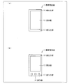
- FIG. 2 is a diagram illustrating an example of the appearance of the mobile phone 1.
- 2A is a diagram illustrating an example of the appearance of the mobile phone 1 equipped with the display unit 13 that is a touch panel.
- FIG. 2B illustrates that the display unit 13 and the operation unit 14 are separated from each other. It is a figure which shows an example of the external appearance of the mounted mobile phone 1.
- Both (a) and (b) of FIG. 2 are views showing the external appearance of the mobile phone 1 as viewed from the front.
- a display unit 13, a sound output unit 16, and a sound input unit 17 are arranged on the front surface of the mobile phone 1.
- the display unit 13, the operation unit 14, the sound output unit 16, and the sound input unit 17 are arranged on the front surface of the mobile phone 1.
- the arrangement of each member included in the mobile phone 1 is not limited to the example shown in FIG. 2 and may be arbitrarily designed.
- the mobile phone 1 includes one sound output unit 16 and one sound input unit 17, but the present invention is not limited to this.
- the mobile phone 1 may include a plurality of sound output units 16 and sound input units 17.
- the mobile phone 1 only needs to include at least one sound output unit 16 and at least one sound input unit 17.
- FIG. 1 is a block diagram showing a main configuration of the mobile phone 1.
- the mobile phone 1 includes a control unit 11, a storage unit 12, a display unit 13, an operation unit 14, a communication unit 15, a sound output unit 16, and a sound input unit 17.
- the display unit 13 displays an image in accordance with instructions from the control unit 11.
- the display unit 13 only needs to display an image in accordance with an instruction from the control unit 11.
- an LCD liquid crystal display
- an organic EL display organic EL display
- a plasma display or the like can be applied.
- the operation unit 14 is for a user to input and operate an instruction signal to the mobile phone 1.
- the operation unit 14 may be configured by an on-hook key, an off-hook key, a function key, a cross key, a numeric keypad, and the like.
- the touch panel with which the operation part 14 and the display part 13 were united may be sufficient like the mobile telephone 1 shown to (a) of FIG.
- the communication unit 15 communicates with other devices by wireless communication means or wired communication means, and exchanges data in accordance with instructions from the control unit 11.
- the sound output unit 16 receives an electrical signal from the control unit 11, converts the received electrical signal into sound, and outputs the sound to the outside of the mobile phone 1.
- the sound output unit 16 is a so-called speaker.
- the sound input unit 17 collects sounds around the mobile phone 1, converts the collected sounds into electric signals, and outputs them to the control unit 11.
- the sound input unit 17 is a so-called microphone.
- the control unit 11 performs various calculations by executing a program read from the storage unit 12 to a temporary storage unit (not shown), and comprehensively controls each unit included in the mobile phone 1. .
- control unit 11 includes, as function blocks, a function control unit (equipment function control unit) 21, an input volume measurement unit (input volume measurement unit) 23, a feedback volume prediction unit (feedback volume prediction unit) 24, a state.
- the configuration includes a determination unit (state determination unit) 25 and a volume determination unit (volume determination unit) 26.
- the function control unit 21 includes an output sound control unit 22.
- Each of the functional blocks (21 to 26) of the control unit 11 includes a program stored in a storage device realized by a CPU (central processing unit), a ROM (read only memory), and the like (random access memory). This can be realized by reading out and executing the temporary storage unit realized by the above.
- the function control unit 21 controls functions provided in the mobile phone 1. For example, the function control unit 21 controls processing such as power ON / OFF, telephone call, mail, Web browsing, and other application execution. The function control unit 21 executes various processes based on user instructions input from the operation unit 14. Moreover, the function control part 21 displays an image on the display part 13 according to a process. The function control unit 21 receives an electrical signal from the sound input unit 17 during a call, for example, and transmits the received electrical signal to another device via the communication unit 15.
- the function control unit 21 switches ON / OFF of the switch function of the sound output unit 16 and the sound input unit 17.
- the trigger which the function control part 21 switches a switch function is not specifically limited.
- the function control unit 21 may switch on / off of the switch function based on a user instruction input from the operation unit 14.
- the function control unit 21 may switch ON / OFF of the switch function when starting a predetermined application, or may switch ON / OFF of the switch function when executing predetermined processing in the predetermined application. .
- the function control unit 21 may activate the switch function at the start of the incoming call process in the call function and stop the switch function at the end of the incoming call process.
- the function control unit 21 causes the output sound control unit 22 described later to start outputting sound from the sound output unit 16 and activates the switch function, and the output sound control unit 22 outputs sound from the sound output unit 16. In addition to stopping, the switch function may be stopped.
- the function control unit 21 includes an output sound control unit 22, and among the processes executed by the function control unit 21, the output sound control unit 22 performs processing related to sound output such as outputting sound from the sound output unit 16. Shall be executed.
- the function control unit 21 includes function blocks that execute functions other than sound output (call, mail, etc.), but they are not shown here because they are not related to the features of the present invention.
- the output sound control unit 22 determines the volume and frequency of the sound to be output, generates a sound wave (waveform) based on the determined volume and frequency, and outputs the generated sound wave to the sound output unit 16 as an electrical signal. For example, the output sound control unit 22 reads the setting value stored in the storage unit 12 when receiving an incoming call, and determines the volume and frequency of the ringing tone based on the read setting value.
- the output sound control unit 22 outputs a determined output sound volume value indicating the determined sound volume of the output sound to the feedback sound volume predicting unit 24. Further, the output sound control unit 22 may output an output sound frequency indicating the determined frequency of the sound to be output to the input sound volume measurement unit 23.
- the input volume measuring unit 23 receives the electrical signal converted by the sound input unit 17 and measures the volume of the sound collected by the sound input unit 17.
- the input volume measuring unit 23 outputs an input volume value indicating the measured volume (input volume) to the volume determining unit 26. Further, the input volume measuring unit 23 may output an input volume value indicating the measured volume to the state determining unit 25.
- the input sound volume measurement unit 23 selects the sound having the same frequency component as the frequency indicated by the received output sound frequency among the sounds collected by the sound input unit 17. The size (volume) may be measured.
- the feedback sound volume prediction unit 24 receives the determined output sound volume value from the output sound control unit 22. Then, the feedback sound volume prediction unit 24 is a sound (feedback sound) that is considered to be collected by the sound input unit 17 when the sound output unit 16 and the sound input unit 17 are in the reference state. Is predicted based on the determined output volume value.
- the feedback volume predicted by the feedback volume prediction unit 24 is referred to as a predicted volume.
- the feedback volume predicting unit 24 outputs a predicted volume value indicating the predicted predicted volume to the volume determining unit 26. Further, the feedback sound volume prediction unit 24 may output a predicted sound volume value indicating the predicted sound volume to the state determination unit 25.
- the sound output unit 16 and the sound input unit 17 are in the reference state” means that an object that blocks the sound output from the sound output unit 16 and collected by the sound input unit 17 is the sound output unit 16 or the sound input unit 17. This is a state that does not exist within a predetermined distance with respect to the position of.
- the object includes an object that covers the sound output unit 16, an object that covers the sound input unit 17, and an object that exists between the sound output unit 16 and the sound input unit 17.
- the above-mentioned “sound that is considered that the sound output from the sound output unit 16 is collected by the sound input unit 17” means that the sound output from the sound output unit 16 is outside the casing of the mobile phone 1. The sound is transmitted through the air and returned to the sound input unit 17 to be collected.
- sound output from the sound output unit 16 propagates through the casing of the electronic device or a member inside the housing to the sound input unit 17. It is designed not to input sound.
- the sound output from the sound output unit 16 is collected by the sound input unit 17.
- Let the sound volume be the ideal feedback volume.
- the “predetermined distance” indicates a distance between the sound output unit 16 or the sound input unit 17 and the object. Outside the “predetermined distance”, even if the object is present around the sound output unit 16 or the sound input unit 17, the sound output from the sound output unit 16 is collected by the sound input unit 17. It is considered that the volume of the sound is substantially different from the ideal feedback volume.
- substantially no difference means that the difference between the input volume measured when the sound output unit 16 and / or the sound input unit 17 is blocked and the ideal feedback volume. It means very small compared to the difference.
- the feedback sound volume prediction unit 24 In order for the feedback sound volume prediction unit 24 to predict the feedback sound volume, the sound input unit when the sound output unit 16 outputs a sound of a predetermined volume in the reference state of the sound output unit 16 and the sound input unit 17 in advance. The feedback sound volume of the feedback sound collected after returning to 17 is measured. Then, based on the measurement result of the feedback sound volume, a calculation formula for converting the determined output sound volume value to the predicted sound volume value or a correspondence table in which the determined output sound volume value and the predicted sound volume value are associated with each other is created in advance. Thereby, the feedback sound volume prediction unit 24 derives the predicted sound volume from the received determined output sound volume value by using the above-described calculation formula or the correspondence table.
- the sound output unit 16 and the sound input unit 17 are in the reference state and the mobile phone 1 is stationary in the air in order to accurately predict the predicted sound volume. It is desirable to perform in a state where there is no other sound source or the like around.
- the state determination unit 25 determines whether or not the sound output unit 16 and the sound input unit 17 are in the reference state. In other words, the state determination unit 25 determines whether or not the sound volume determination unit 26 is in a state where it can be normally determined. When the state determination unit 25 determines that the sound output unit 16 and the sound input unit 17 are in the reference state, the state determination unit 25 notifies the sound volume determination unit 26 of the state determination result. In addition, when the state determination unit 25 determines that the sound output unit 16 and the sound input unit 17 are in the reference state, and when it determines that the sound output unit 16 and the sound input unit 17 are not in the reference state, The state determination result is notified to the function control unit 21.
- the state determination unit 25 determines whether or not the input sound volume measured by the input sound volume measurement unit 23 matches the predicted sound volume predicted by the feedback sound volume prediction unit 24.
- the state determination unit 25 determines that the sound output unit 16 and the sound input unit 17 are in the reference state when the input volume and the predicted volume match, and when the input volume and the predicted volume do not match, It is determined that the sound output unit 16 and the sound input unit 17 are not in the reference state.
- the state determination unit 25 will output the sound output unit 16 and the sound input unit 17. May be determined to be in the reference state. For example, when the sound input unit 17 picks up noise, the input volume and the predicted volume do not completely match, but if the noise level is smaller than the input volume, the noise is ignored and the sound is ignored. There is no problem even if it is determined that the output unit 16 and the sound input unit 17 are in the reference state.
- the predetermined range may be a range that can tolerate noise and a measurement error of the input sound volume measurement unit 23.
- the state determination unit 25 determines whether or not a predetermined time has elapsed after the switch function is activated or the output sound control unit 22 causes the sound output unit 16 to start outputting sound. When the predetermined time has elapsed, the state determination unit 25 determines that the sound output unit 16 and the sound input unit 17 are in the reference state, and when the predetermined time has not elapsed, the sound output unit 16 and the sound input unit 17 are in the reference state. It is determined that it is not.
- the state determination unit 25 determines whether or not the mobile phone 1 is in a state where the switch function can be normally operated.
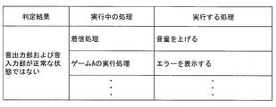
- the function control unit 21 When the function control unit 21 receives a state determination result indicating that the sound output unit 16 and the sound input unit 17 are not in the reference state from the state determination unit 25, the function control unit 21 performs the process being executed and the state determination result. Based on the above, a predetermined operation (second process) is executed. For example, when the function control unit 21 receives a state determination result indicating that the sound output unit 16 and the sound input unit 17 are not in the reference state during execution of the incoming call process, the output control is performed so as to increase the volume of the ringtone.
- the unit 22 may be controlled.
- the function control unit 21 receives a state determination result indicating that the sound output unit 16 and the sound input unit 17 are not in the reference state during execution of the incoming call process. Then, the vibration may be operated. Further, when the function control unit 21 receives a state determination result indicating that the sound output unit 16 and the sound input unit 17 are not in the reference state during execution of an application such as a game, the function control unit 21 and / or A notification that the switch function using the sound input unit 17 does not operate normally (error notification) may be displayed on the display unit 13 to notify the user.
- the function control unit 21 When the function control unit 21 receives a state determination result indicating that the sound output unit 16 and the sound input unit 17 are in the reference state from the state determination unit 25, the function control unit 21 returns to the state before the state determination unit 25 performs the state determination process. return. Specifically, the function control unit 21 controls the output sound control unit 22 to receive a state determination result indicating that it is not in the reference state from the state determination unit 25 and increase the volume of the ringtone. And the function control part 21 will control the output sound control part 22 so that the volume of a ringtone may be lowered
- the function control unit 21 when the function control unit 21 receives a state determination result indicating that it is not in the reference state from the state determination unit 25 and operates the vibration, when the function control unit 21 receives the state determination result indicating the reference state, the vibration control operation Stop. Further, when the function control unit 21 receives the state determination result indicating that it is not in the reference state from the state determination unit 25 and displays the error notification, the function control unit 21 receives the state determination result indicating that the state is the reference state. 13 finishes displaying the error notification.
- the volume determination unit 26 determines whether the input volume measured by the input volume measurement unit 23 is smaller than the predicted volume predicted by the feedback volume prediction unit 24. The sound volume determination unit 26 notifies the function control unit 21 of the sound volume determination result.
- the sound volume determination unit 26 has the input sound volume only when the state determination result indicates that the sound output unit 16 and the sound input unit 17 are in the reference state. It is determined whether or not the volume is lower than the predicted volume.
- the volume determination unit 26 may determine whether or not the input volume measured by the input volume measurement unit 23 is smaller than a predicted value by the predicted volume predicted by the feedback volume prediction unit 24.
- a case where the user stops trying to block the sound output unit 16 or the sound input unit 17 may be considered. Therefore, for example, when the user does not intend (or temporarily) and the sound output unit 16 or the sound input unit 17 is present within a predetermined distance based on the position, the switch function may not be operated. preferable. Therefore, when the sound volume determination unit 26 temporarily blocks the sound output unit 16 or the sound input unit 17 (unintentionally by the user) by determining whether or not the input sound volume is smaller than the predicted sound volume by a predetermined value or more. The malfunction of the switch function can be reduced. In this case, even if the input sound volume temporarily becomes lower than the predicted sound volume due to a measurement error or the like, malfunction of the switch function can be prevented.
- the function control unit 21 receives the sound volume determination result from the sound volume determination unit 26 during activation of the switch function.
- the function control unit 21 receives a sound volume determination result indicating that the input sound volume is smaller than the predicted sound volume
- the function control unit 21 performs a predetermined operation based on the process being executed by the function control unit 21 and the sound volume determination result ( The first process is executed. For example, if the function control unit 21 receives a volume determination result indicating that the input volume is smaller than the predicted volume during the incoming call process, the function control unit 21 may control the output sound control unit 22 to decrease the volume of the ringtone. Good.
- the function control unit 21 controls the output sound control unit 22 so as to stop the output of the ringtone when receiving the volume determination result indicating that the input volume is smaller than the predicted volume during execution of the incoming call process. The process may be shifted from the incoming call process to the answering machine process.
- the function control unit 21 receives a sound volume determination result indicating that the input sound volume is not smaller than the predicted sound volume, the function control unit 21 does not perform a specific process based on the sound volume determination result.
- the storage unit 12 stores programs, data, and the like referred to by the control unit 11.
- the storage unit 12 stores, for example, a switch function operation table that defines an operation to be executed based on a process being executed by the function control unit 21 and a sound volume determination result.
- the storage unit 12 stores, for example, an abnormal operation table that defines an operation to be executed based on a process being executed by the function control unit 21 and a state determination result.
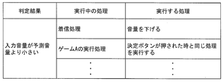
- FIG. 3 is a diagram illustrating an example of a switch function operation table stored in the storage unit 12.
- FIG. 4 is a diagram illustrating an example of an abnormal operation table stored in the storage unit 12.
- the switch function operation table includes a process executed by the function control unit 21 during the activation of the switch function and a function control unit when the volume determination unit 26 determines that the input volume is smaller than the predicted volume.
- 21 is associated with the first process executed by 21.
- the function control unit 21 receives a volume determination result indicating that the input volume is smaller than the predicted volume from the volume determination unit 26
- the function control unit 21 reads the switch function operation table from the storage unit 12 and performs the process currently being executed in the switch function operation table.
- the process associated with is executed. For example, in the example illustrated in FIG.
- the function control unit 21 when receiving a volume determination result indicating that the input volume is smaller than the predicted volume from the volume determination unit 26 during the incoming call process, the function control unit 21 causes the output sound control unit 22 to An instruction is given to lower the volume of the output sound from the sound output unit 16.
- the operation table at the time of abnormality includes the processing executed by the function control unit 21 while the switch function is activated, the state determination unit 25 in the sound output unit 16 and the sound input unit 17 in the reference state. This is associated with the second process executed by the function control unit 21 when it is determined that there is no.
- the function control unit 21 receives a state determination result indicating that the sound output unit 16 and the sound input unit 17 are not in the reference state from the state determination unit 25, the function control unit 21 reads the abnormal operation table from the storage unit 12 and performs an abnormal operation. The process associated with the process currently being executed in the table is executed. For example, in the example illustrated in FIG.
- FIG. 5 is a diagram schematically showing various states of the mobile phone.
- 5A is a diagram illustrating a reference state of the sound output unit 16 and the sound input unit 17 of the mobile phone 1
- FIG. 5B is a diagram in which the sound output unit 16 is covered with a shield 31.
- FIG. 5C is a diagram illustrating a state in which a sound source 32 other than the sound output unit 16 is present around the mobile phone 1.
- a user's finger, palm, or the like is assumed as the shield 31 that closes the sound output unit 16.
- the sound output unit 16 and the sound input unit 17 are in the reference state, the sound output from the sound output unit 16 propagates through the air and returns to the sound input unit 17. And collected. At this time, the sound input unit 17 collects a sound having substantially the same volume as the predicted volume predicted by the feedback volume prediction unit 24.
- the sound output unit 16 (the opening thereof) is covered with the shield 31, the sound output from the sound output unit 16 does not propagate in the air, The sound output from the sound output unit 16 by the input unit 17 is not collected. At this time, the sound input unit 17 collects a sound having a volume smaller than the predicted volume predicted by the feedback volume prediction unit 24.
- the sound output unit 16 determines whether or not the sound input unit 17 has any object (shielding) based on the determination of whether the sound volume input to the sound input unit 17 is lower than the predicted sound volume. It is possible to detect whether or not the object 31 is covered.
- the function control unit 21 when the function control unit 21 receives a sound volume determination result indicating that the input sound volume is smaller than the predicted sound volume, the function control unit 21 performs a predetermined operation. Therefore, the user can cause the mobile phone 1 to execute a predetermined operation by pressing the sound output unit 16 with a finger or the like. In other words, the sound output unit 16 can have the function of the operation unit.
- the sound input unit 17 similarly includes the feedback volume predicting unit 24. Sounds with a volume lower than the predicted predicted volume are collected. Therefore, when the input volume is smaller than the predicted volume, the mobile phone 1 can determine that at least one of the sound output unit 16 and the sound input unit 17 (the opening thereof) is blocked by some object. .
- the sound input unit 17 collects sounds output from the other sound sources 32. Therefore, the sound input unit 17 collects a sound having a volume larger than the predicted volume predicted by the feedback volume prediction unit 24.
- the sound input unit 17 does not collect a sound with a volume smaller than the predicted volume predicted by the feedback volume prediction unit 24. There is a case. That is, even when the sound output unit 16 or the sound input unit 17 is pressed, the sound input unit 17 collects the sound output from the other sound source 32, so that the sound collected by the sound input unit 17 is predicted. It may be larger than the volume.
- the mobile phone 1 when there is another sound source 32 in the vicinity of the mobile phone 1, the mobile phone 1 is configured such that at least one of the sound output unit 16 and the sound input unit 17 is an object. It may not be possible to accurately determine whether or not it is covered.
- the mobile phone 1 when the mobile phone 1 activates the switch function of the sound output unit 16 and the sound input unit 17 and the user unintentionally presses the sound output unit 16 or the sound input unit 17, the user intends Although it is not, the mobile phone 1 performs a predetermined operation.
- the state determination unit 25 determines whether or not the input volume and the predicted volume match, whereby the mobile phone 1 can be It is possible to determine whether the state is a).
- the sound volume determination unit 26 determines whether or not the input sound volume is smaller than the predicted sound volume. And the switch function of the sound input part 17 can be operated correctly.
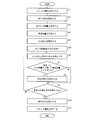
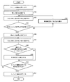
- FIGS. 6 to 8 are flowcharts showing an example of processing of the switch function of the sound output unit 16 and the sound input unit 17 in the mobile phone 1.
- Switch function processing example 1 First, a basic processing example of the switch function processing of the sound output unit 16 and the sound input unit 17 in the mobile phone 1 will be described with reference to FIG.
- the function control unit 21 turns on the switch functions of the sound output unit 16 and the sound input unit 17 (S1).
- the function control unit 21 activates the sound input unit 17 after activating the switch function (S2).
- the output sound control unit 22 determines the volume of the sound to be output from the sound output unit 16 (S3).
- the feedback sound volume prediction unit 24 receives the determined output sound volume value from the output sound control unit 22 and determines the predicted sound volume of the sound that is assumed to be input to the sound input unit 17 by the sound output from the sound output unit 16. Prediction is made based on the output volume value (S4). And the output sound control part 22 produces
- the input volume measuring unit 23 receives the electrical signal converted by the sound input unit 17 and measures the volume of the sound collected by the sound input unit 17 (S6).
- the volume determination unit 26 receives the input volume from the input volume measurement unit 23, receives the predicted volume from the feedback volume prediction unit 24, and determines whether the input volume is smaller than the predicted volume (S7). Then, the volume determination unit 26 transmits a volume determination result indicating whether or not the input volume is smaller than the predicted volume to the function control unit 21.
- the function control unit 21 When the function control unit 21 receives a volume determination result indicating that the input volume is smaller than the predicted volume (YES in S7), the function control unit 21 reads the switch function operation table from the storage unit 12, and is determined based on the switch function operation table. A predetermined operation is executed (S8). On the other hand, when the function control unit 21 receives a volume determination result indicating that the input volume is not smaller than the predicted volume (NO in S7), the function control unit 21 proceeds to S9 without performing the process based on the volume determination result.
- the output sound control unit 22 receives a sound output stop instruction from the sound output unit 16 (YES in S9), the output sound control unit 22 stops sound output from the sound output unit 16 (S10). . Then, the function control unit 21 stops the sound input unit 17 and stops the switch function (S11).
- switch function processing example 2 Next, based on FIG. 7, an example of the process of the switch function for performing volume determination after the mobile phone 1 confirms the reference state will be described.
- the switch function processing example shown in FIG. 7 includes a process of determining the state of the mobile phone 1 between S5 and S6, unlike the switch function processing example shown in FIG. Therefore, here, in the processing example of the switch function shown in FIG. 7, processing different from the processing example of the switch function shown in FIG. 6 will be mainly described.
- the function control unit 21 activates the switch function when the mobile phone 1 receives an incoming call.
- the sound volume determination part 26 shall perform a sound volume determination process, after confirming that the sound output part 16 and the sound input part 17 are a reference
- the processing of S1 to S5 is performed in the same manner as the processing example of the switch function shown in FIG.
- the input volume measuring unit 23 receives the electrical signal converted by the sound input unit 17, and measures the volume of the sound collected by the sound input unit 17 (S21).
- the state determination unit 25 determines whether or not the input sound volume measured by the input sound volume measurement unit 23 matches the predicted sound volume predicted by the feedback sound volume prediction unit 24 (S22).
- the state determination unit 25 determines that the input sound volume and the predicted sound volume do not match (NO in S22)
- the sound volume output from the sound output unit 16 by the output sound control unit 22 of the function control unit 21 is set. (S23).
- the output sound control unit 22 causes the sound output unit 16 to output a sound with a volume larger than the volume determined in S3 (determined output volume value).
- the state determination unit 25 determines that the input volume and the predicted volume match (that is, is in the reference state) (YES in S22)
- the state determination unit 25 notifies the volume determination unit 26 to that effect.
- the output sound control unit 22 of the function control unit 21 sets the volume of the sound output from the sound output unit 16 to the determined output volume value (that is, the volume value determined in S3) (S24).
- the sound volume determination unit 26 performs the sound volume determination process after confirming that the sound output unit 16 and the sound input unit 17 are in the reference state. As a result, when the switch function is activated, it is possible to prevent malfunction due to the user unintentionally pressing the sound output unit 16 or the sound input unit 17.
- the output sound control unit 22 raises the volume of the sound output from the sound output unit 16, thereby not only preventing the malfunction of the switch function but also notifying the user that there is an incoming call. be able to.
- the ringtone volume is returned to the volume set in advance by the user. It is preferable. Therefore, after determining that the state determination unit 25 is in the reference state in S24, the volume of the sound output from the sound output unit 16 by the output sound control unit 22 is set to the determined output volume value.
- FIG. 8 shows a processing example when it is determined that the mobile phone 1 is in the reference state after a predetermined time has elapsed since the switch function was activated.
- the switch function processing example shown in FIG. 8 includes a process of waiting for a predetermined time to elapse between S5 and S6, unlike the switch function processing example shown in FIG. Specifically, the state determination unit 25 determines whether or not a predetermined time has elapsed after the output sound control unit 22 causes the sound output unit 16 to start outputting sound (S5) (S31). When the state determination unit 25 determines that the predetermined time has elapsed, the input volume measurement unit 23 measures the volume of the sound collected by the sound input unit 17 (S6).
- the volume determination unit 26 determines whether or not the user has pressed the sound output unit 16 or the sound input unit 17 by determining whether or not the input volume is smaller than the predicted volume. It is not limited.
- the sound volume determination unit 26 indicates that the sound of the input sound measured by the input sound volume measurement unit 23 (temporal change in input sound volume) is blocked by the sound output unit 16 or the sound input unit 17 being blocked by some object. It may be determined whether or not it matches the waveform of the feedback sound in the state. In this case, the volume determination unit 26 determines that the waveform of the input sound measured by the input volume measurement unit 23 matches the waveform of the feedback sound in a state where the sound output unit 16 or the sound input unit 17 is blocked by some object. In such a case, the function control unit 21 executes the first process.
- the part 26 determines. Thereby, it may be determined whether the user has pressed the sound output unit 16 or the sound input unit 17. In this case, when both waveforms match, it is determined that the user has pressed the sound output unit 16 or the sound input unit 17.
- the sound output unit 16 in a closed state where the sound output unit 16 or the sound input unit 17 is previously blocked by some object, the sound output unit 16 returns to the sound input unit 17 when a sound having a predetermined volume is output. Measure the waveform of the feedback sound collected over time (temporal change in the feedback volume). Based on the measurement result of the feedback volume, the waveform of the feedback sound (blocking state waveform) in a state where the sound output unit 16 or the sound input unit 17 is blocked by some object is determined, and the block state waveform is stored. Stored in the unit 12.
- the volume determination unit 26 reads the blockage state waveform from the storage unit 12, and determines whether the waveform of the input sound measured by the input volume measurement unit 23 matches the blockage state waveform.
- the sound output unit 16 when the sound output unit 16 was previously blocked by some object, the sound output unit 16 was fed back to the sound input unit 17 when the sound output unit 16 output a sound of a predetermined volume.
- An output closed state waveform that is a waveform of feedback sound may be stored in the storage unit 12.
- the sound output unit 16 in a state where the sound input unit 17 is blocked by some object, the sound output unit 16 returns to the sound input unit 17 and collects the sound when the sound output unit 16 outputs a sound of a predetermined volume.
- An input blockage state waveform that is a waveform of feedback sound may be stored in the storage unit 12.
- the sound output unit 16 and the sound input unit 17 are blocked by some object in advance. That is, the input / output is blocked.
- the storage unit stores an input / output block state waveform that is a waveform of the feedback sound collected by returning to the sound input unit 17 12 may be stored.
- the output block state waveform, the input block state waveform, and the input / output block state waveform are stored in the storage unit 12.
- the volume determination unit 26 determines whether the waveform of the input sound measured by the input volume measurement unit 23 matches any of the output blockage state waveform, the input blockage state waveform, or the input / output blockage state waveform. Based on the determination result, it can be determined whether or not both the sound output unit 16 and the sound input unit 17 are closed.
- the sound output unit 16 and the sound input unit 17 are waveforms of feedback sound collected and returned to the sound input unit 17 when a sound having a predetermined volume is output from the sound output unit 16 in the reference state.
- the reference state waveform may be stored in the storage unit 12.
- the determination part 26 determines. Thereby, it can be judged whether it is an obstruction
- the sound output unit 16 returns to the sound input unit 17 when a sound having a predetermined volume is output.
- the waveform of the collected feedback sound may be stored in the storage unit 12. In this case, it can be determined whether the user has blocked the sound output unit 16 or the sound input unit 17 a plurality of times at predetermined intervals.
- the sound output unit 16 returns to the sound input unit 17 when a sound having a predetermined volume is output.
- the waveform of the feedback sound collected in this way may be stored in the storage unit 12. In this case, it can be determined whether the user has blocked the sound output unit 16 or the sound input unit 17 in a specific order.
- the storage unit 12 stores a waveform when each state transitions in a specific order and a waveform when each state transitions at a specific number of times and timing. As a result, the order in which the sound output unit 16 and the sound input unit 17 are blocked, the number of times the sound output unit 16 and the sound input unit 17 are blocked, and the timing can be determined.
- FIGS. 9 and 10 A second embodiment of the present invention will be described with reference to FIGS. 9 and 10 as follows. Unlike the first embodiment, the second embodiment realizes a switch function only with the sound input unit 17 of the mobile phone 1.
- the sound input unit 17 is activated to collect noise around the mobile phone 1 and whether or not the sound input unit 17 is covered with a finger or the like is input. Judgment is made based on a change in the volume of the sound input to the unit 17.
- differences of the second embodiment from the first embodiment will be mainly described.
- members having the same functions as those shown in the first embodiment are given the same reference numerals, and explanation thereof is omitted.
- FIG. 9 is a block diagram showing a main configuration of the mobile phone 40.
- the mobile phone 40 includes a control unit 41, a storage unit 12, a display unit 13, an operation unit 14, a communication unit 15, and a sound input unit 17.
- the mobile phone 40 according to the second embodiment may also include the sound output unit 16, but as described above, the present embodiment realizes a switch function only by the sound input unit 17. Therefore, it is not shown here.
- the control unit 41 executes various programs by executing a program read from the storage unit 12 to a temporary storage unit (not shown), and comprehensively controls each unit included in the mobile phone 40. .
- control unit 41 includes a function control unit 21, an input volume measurement unit 23, a sound determination unit 27, a normal input volume determination unit 28, and a volume determination unit 29 as function blocks.
- the CPU reads a program stored in a storage device realized by a ROM or the like to a temporary storage unit realized by a RAM or the like. It can be realized by executing.
- the function control unit 21 controls functions provided in the mobile phone 1 and may include an output sound control unit 22 as in the first embodiment. However, the function control unit 21 is related to the features of the present embodiment. This is not shown here.
- the input volume measuring unit 23 receives the electrical signal converted by the sound input unit 17 and measures the volume of the sound collected by the sound input unit 17 as in the first embodiment.
- the input volume measuring unit 23 outputs an input volume value indicating the measured volume (input volume) to the sound determination unit 27, the normal input volume determination unit 28, and the volume determination unit 29.
- the sound determination unit 27 determines whether or not the input volume value indicating the input volume measured by the input volume measurement unit 23 is within a predetermined effective range. When the sound determination unit 27 determines that the input sound volume value is within the predetermined effective range, the sound determination unit 27 notifies the normal input sound volume determination unit 28 of the sound determination result. Further, when the sound determination unit 27 determines that the input sound volume value is not within the predetermined effective range, the sound determination unit 27 notifies the function control unit 21 of the sound determination result.
- the above-mentioned effective range is a range determined by a predetermined lower limit value and a predetermined upper limit value. That is, the sound determination unit 27 determines whether or not the sound input unit 17 is collecting a sound having a predetermined volume. When the sound input unit 17 collects a sound with a certain volume, when the sound input unit 17 is pressed, the sound input unit 17 inputs the sound input unit 17 because the sound volume suddenly decreases. It is possible to determine whether or not the sound input unit 17 is pressed based on the change in volume of the sound to be played.
- the sound input unit 17 if the sound collected by the sound input unit 17 has a very low volume, the sound input unit 17 hardly changes even when the sound input unit 17 is pressed. It cannot be determined whether the part 17 is pressed.
- the sound determination unit 27 determines whether or not the input sound volume value is within a predetermined effective range, the current state of the mobile phone 40 causes the switch function of the sound input unit 17 to operate correctly. Can be determined.
- the normal input volume determination unit 28 When the normal input volume determination unit 28 receives a sound determination result indicating that the input sound volume value is within a predetermined effective range from the sound determination unit 27, the input sound volume value used by the sound determination unit 27 is determined. The normal input volume value is determined based on the input volume value measured by the input volume measuring unit 23 within a predetermined period including the measured time point. The normal input volume determination unit 28 outputs the determined normal input volume value to the volume determination unit 29.
- the normal input volume value indicates a reference value of noise generated around the mobile phone 40 within the predetermined period.
- the normal input volume determination unit 28 may set a value obtained by averaging the input volume values measured by the input volume measurement unit 23 within the predetermined period as the normal input volume value. Further, the normal input volume determination unit 28 may use, for example, the median value of the input volume values measured by the input volume measurement unit 23 within the predetermined period as the normal input volume value. Further, the normal input volume determination unit 28 may set, for example, the lower limit value of the input volume value measured by the input volume measurement unit 23 within the predetermined period as the normal input volume value. Further, the normal input volume determination unit 28 may use, for example, the lower limit value of the predetermined effective range as the normal input volume value.
- the volume determination unit 29 receives the current input volume value from the input volume measurement unit 23, receives the normal input volume value from the normal input volume determination unit 28, and determines whether or not the input volume value is smaller than the normal input volume value. Judgment. The volume determination unit 29 notifies the function control unit 21 of the volume determination result.
- the volume determination unit 29 may determine whether or not the input volume value is smaller than the normal input volume value by a predetermined value or more. Since the volume of noise generated around the mobile phone 40 fluctuates, the input volume value may be smaller than the normal input volume value even if the sound input unit 17 is not blocked. In this case, since the user does not intend, it is preferable not to operate the switch function. Therefore, the malfunction of the switch function can be reduced by determining whether or not the input volume value is smaller than the normal input volume value by the volume determination unit 29. In this case, even if the input sound volume temporarily becomes smaller than the normal input sound volume value due to a measurement error or the like, malfunction of the switch function can be prevented.
- the function control unit 21 When the function control unit 21 receives a volume determination result indicating that the input volume value is smaller than the normal input volume value from the volume determination unit 29, the function control unit 21 performs the process being performed by the function control unit 21 and the volume determination result. Perform a predetermined action.
- the function control unit 21 when the function control unit 21 receives a sound determination result indicating that the input sound volume value is not within the predetermined effective range from the sound determination unit 27, the function control unit 21 displays on the display unit 13 that it is outside the effective range. To do.
- FIG. 10 is a flowchart illustrating an example of processing of the switch function of the sound input unit 17 in the mobile phone 40.
- the function control unit 21 turns on the switch function of the sound input unit 17 (S41). After activating the switch function, the function control unit 21 activates the sound input unit 17 (S42).
- the input volume measuring unit 23 receives the electrical signal converted by the sound input unit 17, and measures the volume of the sound collected by the sound input unit 17 (S43). Then, the sound determination unit 27 determines whether or not the input volume value indicating the input volume measured by the input volume measurement unit 23 is within a predetermined effective range (S44).
- the function control unit 21 displays on the display unit 13 that it is outside the effective range (S45). . Then, the process returns to S43.
- the sound determination unit 27 determines that the input sound volume value is within the predetermined effective range (YES in S43)
- the normal input sound volume determination unit 28 uses the input sound volume value used by the sound determination unit 27 for the determination. The normal input volume value is determined based on the input volume value measured by the input volume measuring unit 23 within a predetermined period including the time point at which is measured (S46).
- the input volume measurement unit 23 receives the electrical signal converted by the sound input unit 17 and measures the volume of the sound collected by the sound input unit 17. (S47).
- the volume determination unit 29 receives the input volume value from the input volume measurement unit 23, receives the normal input volume value from the normal input volume determination unit 28, and determines whether the input volume value is smaller than the normal input volume value. (S48).
- the function control unit 21 When the function control unit 21 receives a volume determination result indicating that the input volume value is smaller than the normal input volume value (YES in S48), the function control unit 21 executes a predetermined operation (S49). On the other hand, when the function control unit 21 receives a volume determination result indicating that the input volume value is not smaller than the normal input volume value (NO in S48), the function control unit 21 proceeds to S50 without performing the process based on the volume determination result.
- the function control unit 21 when the function control unit 21 receives an instruction to stop the switch function (YES in S50), the function control unit 21 stops the sound input unit 17 and stops the switch function (S51).
- the process may return to S43 instead of returning to S47.
- the sound volume determination unit 29 can always execute when the sound collected by the sound input unit 17 is within the effective range.
- each block of the cellular phones 1 and 40 in particular, the control units 11 and 41 may be configured by hardware logic, or may be realized by software using a CPU as follows.
- the cellular phones 1 and 40 are storage devices such as a CPU that executes instructions of a control program for realizing each function, a ROM that stores the program, a RAM that expands the program, a memory that stores the program and various data, and the like.
- An object of the present invention is a recording medium in which the program code (execution format program, intermediate code program, source program) of the control program of the mobile phones 1 and 40, which is software that realizes the functions described above, is recorded so as to be readable by a computer Can also be achieved by reading the program code recorded on the recording medium and executing it by the computer (or CPU or MPU).
- Examples of the recording medium include tapes such as magnetic tapes and cassette tapes, magnetic disks such as floppy (registered trademark) disks / hard disks, and disks including optical disks such as CD-ROM / MO / MD / DVD / CD-R.
- Card system such as IC card, IC card (including memory card) / optical card, or semiconductor memory system such as mask ROM / EPROM / EEPROM / flash ROM.
- the mobile phones 1 and 40 may be configured to be connectable to a communication network, and the program code may be supplied via the communication network.
- the communication network is not particularly limited.
- the Internet intranet, extranet, LAN, ISDN, VAN, CATV communication network, virtual private network, telephone line network, mobile communication network, satellite communication. A net or the like is available.
- the transmission medium constituting the communication network is not particularly limited.
- infrared rays such as IrDA and remote control, Bluetooth ( (Registered trademark), 802.11 wireless, HDR, mobile phone network, satellite line, terrestrial digital network, and the like can also be used.
- the present invention can also be realized in the form of a computer data signal embedded in a carrier wave in which the program code is embodied by electronic transmission.
- the electronic apparatus further includes a state determination unit that determines whether or not the sound output unit and the sound input unit are in the reference state, and the volume determination unit includes the state determination unit that outputs the sound output. After determining that the sound input unit and the sound input unit are in the reference state, it is preferable to determine whether or not the input sound volume is smaller than the predicted sound volume.
- the state determination unit determines whether or not the sound output unit and the sound input unit are in a reference state.
- the volume determination unit determines whether the input volume is smaller than the predicted volume after the state determination unit determines that the sound output unit and the sound input unit are in a reference state.
- the input sound volume is determined to be the predicted sound volume only when there is no shield that blocks the sound output from the sound output unit and collected by the sound input unit at least once. It is determined whether it is smaller.
- the state determination unit when the state determination unit substantially matches the input volume measured by the input volume measurement unit and the predicted volume predicted by the feedback volume prediction unit, the sound output unit and It is preferable to determine that the sound input unit is in the reference state.
- the state determination unit includes the sound output unit and the sound output unit when the input volume measured by the input volume measurement unit and the predicted volume predicted by the feedback volume prediction unit substantially match. It is determined that the sound input unit is in the reference state.
- the predicted sound volume is a sound volume in which the sound output from the sound output unit in the reference state is predicted to be input to the sound input unit. Therefore, when the input volume measured by the input volume measuring means matches the predicted volume, it is considered that the measurement time of the input volume measuring means is the reference state.
- the state determination unit determines whether or not the input volume measured by the input volume measurement unit substantially matches the predicted volume predicted by the feedback volume prediction unit, thereby determining the input volume measurement unit. It is possible to accurately determine whether or not the measurement time is in the reference state.
- the state determination unit may determine that the sound output unit and the sound input unit are in the reference state after a predetermined period has elapsed since the start of sound output of the sound output unit. preferable.
- the sound output unit and the sound input unit are activated as the operation unit, it is possible that the user does not intend to block the sound output unit or the sound input unit at the time of activation.
- the user when the sound output unit and the sound input unit are activated as an operation unit when an incoming call is received, the user cannot basically predict the incoming call timing. There is a possibility of gripping.
- the state determination unit determines that the sound output unit and the sound input unit are in the reference state after a predetermined period has elapsed since the start of sound output of the sound output unit.
- the sound volume determination means determines whether or not the input sound volume is smaller than the predicted sound volume after a predetermined period has elapsed from the start of sound output of the sound output unit. That is, the sound output unit and the sound input unit can function as an operation unit after a predetermined period has elapsed since the start of sound output of the sound output unit.
- the device function control unit may execute a predetermined second process when the state determination unit determines that the sound output unit and the sound input unit are not in a reference state. preferable.
- the device function control unit executes a predetermined second process when the state determination unit determines that the sound output unit and the sound input unit are not in the reference state.
- the second process is defined as a process for notifying the user that the sound output unit and the sound input unit are not in the reference state.
- the device function control unit can notify the user to that effect. Therefore, it is possible to prompt the user to set the sound output unit and the sound input unit to the reference state.
- the predetermined second process is a process for increasing the volume of the ringtone.
- the device function control unit increases the volume of the ringtone when receiving a call.
- the case where the sound output unit and the sound input unit are not in the reference state may be a case where the sound output unit is blocked by some object, and even though there is an incoming call, The ringtone may not have arrived.
- the device function control unit increases the volume of the ring tone. Therefore, it is possible to more reliably notify the user who is not aware of the incoming call that there is an incoming call.
- the input volume measuring means may measure the volume of the same frequency component as the sound output from the sound output unit among the sounds input to the sound input unit. preferable.
- the input volume measuring means measures the volume of the same frequency component as the sound output from the sound output unit among the sounds input to the sound input unit. Therefore, even when the sound input unit collects sound other than the sound output from the sound output unit, the input volume measuring means extracts only the sound output from the sound output unit. The sound volume can be measured.
- the sound output unit outputs the sound between the sound output unit and the sound input unit. It is possible to accurately determine whether there is an object that blocks the generated sound or a reference state.
- the present invention can be used for an electronic device including a sound output unit and a sound input unit.
Landscapes
- Engineering & Computer Science (AREA)
- Theoretical Computer Science (AREA)
- Signal Processing (AREA)
- Human Computer Interaction (AREA)
- General Engineering & Computer Science (AREA)
- Health & Medical Sciences (AREA)
- Audiology, Speech & Language Pathology (AREA)
- General Health & Medical Sciences (AREA)
- Physics & Mathematics (AREA)
- Multimedia (AREA)
- General Physics & Mathematics (AREA)
- Computer Networks & Wireless Communication (AREA)
- Telephone Function (AREA)
Abstract
Description
上述のように、携帯電話機の操作に不慣れなユーザは、どのキーで着信音のボリュームを下げる(消音にする)ことができるのかがわからない。そのため、ユーザが着信時に周囲に音が響かないようにするために、スピーカを覆うように指で押さえることが考えられる。本発明者らは、このように、スピーカを指等で押さえることにより、実際に、スピーカからの音の出力が停止されるように制御できれば、ユーザにとって直感的に操作ができると考えた。さらに、スピーカから出力される音をマイクで集音する。スピーカが指等で押さえられている時の出力音と、スピーカが指等で押さえられていない時の出力音とを判別する。これによって、新たなセンサやキー等を設けることなく、スピーカが押さえられていることを検知することができると考えた。
<第1の実施形態>
本発明の第1の実施形態について図1から図8に基づいて説明すると以下の通りである。
図2は、携帯電話機1の外観の一例を示す図である。図2の(a)は、タッチパネルである表示部13を搭載した携帯電話機1の外観の一例を示す図であり、図2の(b)は、表示部13と操作部14とが別体となって搭載されている携帯電話機1の外観の一例を示す図である。図2の(a)および(b)共に、携帯電話機1を正面から見た外観を示す図である。
図1は、携帯電話機1の要部構成を示すブロック図である。図1に示すように、携帯電話機1は、制御部11、記憶部12、表示部13、操作部14、通信部15、音出力部16および音入力部17を備えている。
次に、携帯電話機の各種状態について図5に基づいて説明する。図5は、携帯電話機の各種状態を模式的に示す図である。図5の(a)は、携帯電話機1の音出力部16および音入力部17の基準状態を示す図であり、図5の(b)は、音出力部16が遮蔽物31で覆われている状態を示す図であり、図5の(c)は、音出力部16以外の他の音源32が携帯電話機1の周囲に存在する状態を示す図である。なお、本実施形態では、音出力部16を塞ぐ遮蔽物31として、例えば、ユーザの指、手のひら等を想定している。
次に、携帯電話機1における音出力部16および音入力部17のスイッチ機能の処理について図6~8に基づいて説明する。図6~8は、携帯電話機1における音出力部16および音入力部17のスイッチ機能の処理の一例を示すフローチャートである。
まず、図6に基づいて、携帯電話機1における音出力部16および音入力部17のスイッチ機能の処理の基本的な処理例を説明する。
次に、図7に基づいて、携帯電話機1が基準状態を確認した後に、音量判定を実行するスイッチ機能の処理の一例を説明する。図7に示すスイッチ機能の処理例は、図6に示すスイッチ機能の処理例と異なり、S5とS6との間に、携帯電話機1の状態を判定する処理を含む。そのため、ここでは、図7に示すスイッチ機能の処理例において、図6に示すスイッチ機能の処理例と異なる処理について主に説明する。
次に、図8に基づいて、携帯電話機1が基準状態を確認した後に、音量判定を実行するスイッチ機能の処理の別の一例を説明する。図8は、スイッチ機能を起動させてから所定時間経過したことによって、携帯電話機1が基準状態であると判断する場合の処理例を示す。
本実施形態では、音量判定部26が入力音量が予測音量より小さいか否かを判定することにより、ユーザが音出力部16または音入力部17を押さえたかどうかを判断しているが、これに限るものではない。
<第2の実施形態>
本発明の第2の実施形態について図9および図10に基づいて説明すると以下の通りである。第2の実施形態は、第1の実施形態と異なり、携帯電話機1の音入力部17だけでスイッチ機能を実現するものである。具体的には、第2の実施形態では、音入力部17を起動させて、携帯電話機1の周囲の雑音を集音し、音入力部17を指等で覆っているか否かを、音入力部17に入力される音の大きさの変化に基づいて判断する。以下では、主に、第2の実施形態において、第1の実施形態と異なる点について説明する。なお、説明の便宜上、上記の第1の実施形態において示した部材と同一の機能を有する部材には、同一の符号を付し、その説明を省略する。
図9は、携帯電話機40の要部構成を示すブロック図である。図9に示すように、携帯電話機40は、制御部41、記憶部12、表示部13、操作部14、通信部15および音入力部17を備えている。なお、第2の実施形態に係る携帯電話機40も、音出力部16を備えていてもよいが、上述のように、本実施形態は、音入力部17だけでスイッチ機能を実現するものであるため、ここでは図示しない。
次に、携帯電話機40における音入力部17のスイッチ機能の処理について図10に基づいて説明する。図10は、携帯電話機40における音入力部17のスイッチ機能の処理の一例を示すフローチャートである。
<補足>
本発明は上述した各実施形態に限定されるものではなく、請求項に示した範囲で種々の変更が可能であり、異なる実施形態にそれぞれ開示された技術的手段を適宜組み合わせて得られる実施形態についても本発明の技術的範囲に含まれる。
11 制御部
12 記憶部
16 音出力部
17 音入力部
21 機能制御部(機器機能制御手段)
22 出力音制御部
23 入力音量測定部(入力音量測定手段)
24 帰還音量予測部(帰還音量予測手段)
25 状態判定部(状態判定手段)
26 音量判定部(音量判定手段)
Claims (9)
- 音出力部および音入力部を備える電子機器であって、
上記音出力部の音出力時に、上記音入力部に入力された音の大きさを測定する入力音量測定手段と、
上記音出力部から出力されて上記音入力部で集音される音を遮る物体が上記音出力部または上記音入力部の位置を基準とした所定距離内に存在しない状態である基準状態において、上記音出力部から出力された音が上記音入力部に入力される音の大きさを予測する帰還音量予測手段と、
上記入力音量測定手段が測定した入力音量が、上記帰還音量予測手段が予測した予測音量より小さいか否かを判定する音量判定手段と、
上記音量判定手段が上記入力音量が上記予測音量より小さいと判定した場合、所定の第1の処理を実行する機器機能制御手段とを備えることを特徴とする電子機器。 - 上記音出力部および上記音入力部が上記基準状態にあるか否かを判定する状態判定手段をさらに備え、
上記音量判定手段は、上記状態判定手段が上記音出力部および上記音入力部が上記基準状態にあると判定した後に、上記入力音量が上記予測音量より小さいか否かを判定することを特徴とする請求項1に記載の電子機器。 - 上記状態判定手段は、上記入力音量測定手段が測定した入力音量と、上記帰還音量予測手段が予測した予測音量とが略一致している場合、上記音出力部および上記音入力部が上記基準状態にあると判定することを特徴とする請求項2に記載の電子機器。
- 上記状態判定手段は、上記音出力部の音出力開始時から所定期間経過した後、上記音出力部および上記音入力部が上記基準状態にあると判定することを特徴とする請求項2に記載の電子機器。
- 上記機器機能制御手段は、上記状態判定手段が上記音出力部および上記音入力部が基準状態にないと判定した場合、所定の第2の処理を実行することを特徴とする請求項3に記載の電子機器。
- 上記入力音量測定手段は、上記音入力部に入力された音のうち、上記音出力部から出力された音と同じ周波数成分の音の大きさを測定することを特徴とする請求項1~5の何れか1項に記載の電子機器。
- 音出力部および音入力部を備える電子機器の制御方法であって、
上記音出力部の音出力時に、上記音入力部に入力された音の大きさを測定する入力音量測定ステップと、
上記音出力部から出力されて上記音入力部で集音される音を遮る物体が上記音出力部または上記音入力部の位置を基準とした所定距離内に存在しない状態である基準状態において、上記音出力部から出力された音が上記音入力部に入力される音の大きさを予測する帰還音量予測ステップと、
上記入力音量測定ステップにおいて測定された入力音量が、上記帰還音量予測ステップにおいて予測された予測音量より小さいか否かを判定する音量判定ステップと、
上記音量判定ステップにおいて上記入力音量が上記予測音量より小さいと判定された場合、所定の第1の処理を実行する機器機能制御ステップとを含むことを特徴とする電子機器の制御方法。 - 請求項1~6の何れか1項に記載の電子機器を動作させるための制御プログラムであって、コンピュータを上記各手段として機能させるための制御プログラム。
- 請求項8に記載の制御プログラムを記録したコンピュータ読み取り可能な記録媒体。
Priority Applications (2)
| Application Number | Priority Date | Filing Date | Title |
|---|---|---|---|
| CN201280003502.9A CN103202006B (zh) | 2011-02-17 | 2012-02-16 | 电子设备、以及电子设备的控制方法 |
| US13/878,428 US9397628B2 (en) | 2011-02-17 | 2012-02-16 | Electronic device, controlling method and controlling program for electronic device, and recording medium |
Applications Claiming Priority (2)
| Application Number | Priority Date | Filing Date | Title |
|---|---|---|---|
| JP2011-032517 | 2011-02-17 | ||
| JP2011032517A JP5809418B2 (ja) | 2011-02-17 | 2011-02-17 | 電子機器、電子機器の制御方法、制御プログラムおよび記録媒体 |
Publications (1)
| Publication Number | Publication Date |
|---|---|
| WO2012111740A1 true WO2012111740A1 (ja) | 2012-08-23 |
Family
ID=46672652
Family Applications (1)
| Application Number | Title | Priority Date | Filing Date |
|---|---|---|---|
| PCT/JP2012/053641 Ceased WO2012111740A1 (ja) | 2011-02-17 | 2012-02-16 | 電子機器、電子機器の制御方法、制御プログラムおよび記録媒体 |
Country Status (4)
| Country | Link |
|---|---|
| US (1) | US9397628B2 (ja) |
| JP (1) | JP5809418B2 (ja) |
| CN (1) | CN103202006B (ja) |
| WO (1) | WO2012111740A1 (ja) |
Families Citing this family (8)
| Publication number | Priority date | Publication date | Assignee | Title |
|---|---|---|---|---|
| GB2533781A (en) * | 2014-12-29 | 2016-07-06 | Nokia Technologies Oy | Method and apparatus for controlling an application |
| EP3282345B1 (en) * | 2015-04-09 | 2019-05-08 | Fujitsu Limited | Drive control device, electronic equipment, drive control program, and drive control method |
| CN104869240A (zh) * | 2015-05-04 | 2015-08-26 | 深圳市金立通信设备有限公司 | 一种终端 |
| CN104967728A (zh) * | 2015-05-04 | 2015-10-07 | 深圳市金立通信设备有限公司 | 一种语音通信方法 |
| CN105307012B (zh) * | 2015-11-20 | 2019-06-14 | 青岛海信电器股份有限公司 | 一种电视音量调节方法及装置 |
| US9798512B1 (en) * | 2016-02-12 | 2017-10-24 | Google Inc. | Context-based volume adjustment |
| CN107509153B (zh) * | 2017-08-18 | 2020-01-14 | Oppo广东移动通信有限公司 | 声音播放器件的检测方法、装置、存储介质及终端 |
| CN109495635A (zh) * | 2018-12-04 | 2019-03-19 | 闻泰通讯股份有限公司 | 音量调节方法及装置 |
Citations (4)
| Publication number | Priority date | Publication date | Assignee | Title |
|---|---|---|---|---|
| JPH11205199A (ja) * | 1998-01-09 | 1999-07-30 | Nec Corp | 音声スイッチ |
| JP2003319018A (ja) * | 2002-04-24 | 2003-11-07 | Nec Corp | 携帯電話機 |
| JP2008271062A (ja) * | 2007-04-19 | 2008-11-06 | Casio Hitachi Mobile Communications Co Ltd | 携帯端末装置及びプログラム |
| JP2010258701A (ja) * | 2009-04-23 | 2010-11-11 | Ntt Docomo Inc | 通信端末及び音量レベルの調整方法 |
Family Cites Families (6)
| Publication number | Priority date | Publication date | Assignee | Title |
|---|---|---|---|---|
| JPH1079978A (ja) | 1996-09-04 | 1998-03-24 | Tac:Kk | 無線通信機器の呼出装置 |
| US6360187B1 (en) * | 1999-06-28 | 2002-03-19 | Ford Global Technologies, Inc. | Ambient adjusted volume control for in-vehicles messages |
| JP2005244579A (ja) | 2004-02-26 | 2005-09-08 | Sharp Corp | 電話機 |
| US7996048B1 (en) * | 2006-12-22 | 2011-08-09 | At&T Mobility Ii Llc | Enhanced call reception and privacy |
| CN101800809A (zh) * | 2010-01-22 | 2010-08-11 | 中兴通讯股份有限公司 | 一种调节通信终端的通话音量的方法及该通信终端 |
| JP5577732B2 (ja) * | 2010-02-17 | 2014-08-27 | ソニー株式会社 | 情報処理装置 |
-
2011
- 2011-02-17 JP JP2011032517A patent/JP5809418B2/ja not_active Expired - Fee Related
-
2012
- 2012-02-16 WO PCT/JP2012/053641 patent/WO2012111740A1/ja not_active Ceased
- 2012-02-16 US US13/878,428 patent/US9397628B2/en not_active Expired - Fee Related
- 2012-02-16 CN CN201280003502.9A patent/CN103202006B/zh not_active Expired - Fee Related
Patent Citations (4)
| Publication number | Priority date | Publication date | Assignee | Title |
|---|---|---|---|---|
| JPH11205199A (ja) * | 1998-01-09 | 1999-07-30 | Nec Corp | 音声スイッチ |
| JP2003319018A (ja) * | 2002-04-24 | 2003-11-07 | Nec Corp | 携帯電話機 |
| JP2008271062A (ja) * | 2007-04-19 | 2008-11-06 | Casio Hitachi Mobile Communications Co Ltd | 携帯端末装置及びプログラム |
| JP2010258701A (ja) * | 2009-04-23 | 2010-11-11 | Ntt Docomo Inc | 通信端末及び音量レベルの調整方法 |
Also Published As
| Publication number | Publication date |
|---|---|
| JP2012175186A (ja) | 2012-09-10 |
| US9397628B2 (en) | 2016-07-19 |
| US20130195280A1 (en) | 2013-08-01 |
| CN103202006A (zh) | 2013-07-10 |
| CN103202006B (zh) | 2016-02-17 |
| JP5809418B2 (ja) | 2015-11-10 |
Similar Documents
| Publication | Publication Date | Title |
|---|---|---|
| JP5809418B2 (ja) | 電子機器、電子機器の制御方法、制御プログラムおよび記録媒体 | |
| CN105187594B (zh) | 一种消除回声的方法和装置 | |
| JP4616385B2 (ja) | タップ音検出回路を備える通信端末 | |
| EP2230590A3 (en) | Method and apparatus for preventing on-screen keys from being accidentally touched and recording medium using the same | |
| WO2013021858A1 (ja) | 情報入力ユニット及び情報入力方法並びにコンピュータプログラム | |
| US11743355B2 (en) | Prompting method and device | |
| US20180246591A1 (en) | Method of controlling a mobile device | |
| US20110050578A1 (en) | Electronic device with switchable input modes and method thereof | |
| CN101370053A (zh) | 移动终端及耳机控制移动终端进行操作的方法 | |
| CN103019563A (zh) | 一种快速让视频播放器暂停或静音的方法或装置 | |
| CN109521923A (zh) | 悬浮窗控制方法、装置及存储介质 | |
| CN105185396B (zh) | 一种播放音频信号的方法和装置 | |
| CN103513888B (zh) | 电子设备和控制方法 | |
| CN105824524A (zh) | 一种启动应用程序的方法及移动终端 | |
| JP2008141688A (ja) | 携帯端末機器 | |
| WO2012124776A1 (ja) | 電子機器、電子機器の制御方法、制御プログラムおよび記録媒体 | |
| CN101616499B (zh) | 无线通讯装置及其操作方法 | |
| JP6018408B2 (ja) | 情報処理プログラム、情報処理装置、情報処理システム及び情報処理方法 | |
| KR102197912B1 (ko) | 제스처 인식에 따른 기능 실행 방법, 장치 및 기록매체 | |
| US20130210495A1 (en) | Mobile telephone and its display control method | |
| JP2013197659A (ja) | 携帯情報端末 | |
| JP2012165238A (ja) | 端末装置、消音方法およびプログラム | |
| JP2018198398A (ja) | 情報処理装置、情報処理装置の制御方法、および、情報処理装置としてコンピュータを機能させるためのプログラム | |
| KR101155764B1 (ko) | 고성 통화 억제기능을 갖는 단말기 | |
| KR20080092229A (ko) | 휴대단말기의 터치스크린 제어 장치 및 방법 |
Legal Events
| Date | Code | Title | Description |
|---|---|---|---|
| WWE | Wipo information: entry into national phase |
Ref document number: 201280003502.9 Country of ref document: CN |
|
| 121 | Ep: the epo has been informed by wipo that ep was designated in this application |
Ref document number: 12746637 Country of ref document: EP Kind code of ref document: A1 |
|
| WWE | Wipo information: entry into national phase |
Ref document number: 13878428 Country of ref document: US |
|
| NENP | Non-entry into the national phase |
Ref country code: DE |
|
| 122 | Ep: pct application non-entry in european phase |
Ref document number: 12746637 Country of ref document: EP Kind code of ref document: A1 |