WO2012111702A1 - 集電体用三次元網状アルミニウム多孔体及びその製造方法 - Google Patents
集電体用三次元網状アルミニウム多孔体及びその製造方法 Download PDFInfo
- Publication number
- WO2012111702A1 WO2012111702A1 PCT/JP2012/053518 JP2012053518W WO2012111702A1 WO 2012111702 A1 WO2012111702 A1 WO 2012111702A1 JP 2012053518 W JP2012053518 W JP 2012053518W WO 2012111702 A1 WO2012111702 A1 WO 2012111702A1
- Authority
- WO
- WIPO (PCT)
- Prior art keywords
- porous body
- aluminum
- aluminum porous
- current collector
- compressed
- Prior art date
- Legal status (The legal status is an assumption and is not a legal conclusion. Google has not performed a legal analysis and makes no representation as to the accuracy of the status listed.)
- Ceased
Links
Images





Classifications
-
- H—ELECTRICITY
- H01—ELECTRIC ELEMENTS
- H01G—CAPACITORS; CAPACITORS, RECTIFIERS, DETECTORS, SWITCHING DEVICES, LIGHT-SENSITIVE OR TEMPERATURE-SENSITIVE DEVICES OF THE ELECTROLYTIC TYPE
- H01G11/00—Hybrid capacitors, i.e. capacitors having different positive and negative electrodes; Electric double-layer [EDL] capacitors; Processes for the manufacture thereof or of parts thereof
- H01G11/66—Current collectors
- H01G11/70—Current collectors characterised by their structure
-
- H—ELECTRICITY
- H01—ELECTRIC ELEMENTS
- H01M—PROCESSES OR MEANS, e.g. BATTERIES, FOR THE DIRECT CONVERSION OF CHEMICAL ENERGY INTO ELECTRICAL ENERGY
- H01M4/00—Electrodes
- H01M4/02—Electrodes composed of, or comprising, active material
- H01M4/64—Carriers or collectors
- H01M4/70—Carriers or collectors characterised by shape or form
- H01M4/80—Porous plates, e.g. sintered carriers
-
- H—ELECTRICITY
- H01—ELECTRIC ELEMENTS
- H01G—CAPACITORS; CAPACITORS, RECTIFIERS, DETECTORS, SWITCHING DEVICES, LIGHT-SENSITIVE OR TEMPERATURE-SENSITIVE DEVICES OF THE ELECTROLYTIC TYPE
- H01G11/00—Hybrid capacitors, i.e. capacitors having different positive and negative electrodes; Electric double-layer [EDL] capacitors; Processes for the manufacture thereof or of parts thereof
- H01G11/66—Current collectors
-
- H—ELECTRICITY
- H01—ELECTRIC ELEMENTS
- H01G—CAPACITORS; CAPACITORS, RECTIFIERS, DETECTORS, SWITCHING DEVICES, LIGHT-SENSITIVE OR TEMPERATURE-SENSITIVE DEVICES OF THE ELECTROLYTIC TYPE
- H01G11/00—Hybrid capacitors, i.e. capacitors having different positive and negative electrodes; Electric double-layer [EDL] capacitors; Processes for the manufacture thereof or of parts thereof
- H01G11/66—Current collectors
- H01G11/68—Current collectors characterised by their material
-
- H—ELECTRICITY
- H01—ELECTRIC ELEMENTS
- H01G—CAPACITORS; CAPACITORS, RECTIFIERS, DETECTORS, SWITCHING DEVICES, LIGHT-SENSITIVE OR TEMPERATURE-SENSITIVE DEVICES OF THE ELECTROLYTIC TYPE
- H01G11/00—Hybrid capacitors, i.e. capacitors having different positive and negative electrodes; Electric double-layer [EDL] capacitors; Processes for the manufacture thereof or of parts thereof
- H01G11/74—Terminals, e.g. extensions of current collectors
-
- H—ELECTRICITY
- H01—ELECTRIC ELEMENTS
- H01M—PROCESSES OR MEANS, e.g. BATTERIES, FOR THE DIRECT CONVERSION OF CHEMICAL ENERGY INTO ELECTRICAL ENERGY
- H01M10/00—Secondary cells; Manufacture thereof
- H01M10/05—Accumulators with non-aqueous electrolyte
- H01M10/052—Li-accumulators
-
- H—ELECTRICITY
- H01—ELECTRIC ELEMENTS
- H01M—PROCESSES OR MEANS, e.g. BATTERIES, FOR THE DIRECT CONVERSION OF CHEMICAL ENERGY INTO ELECTRICAL ENERGY
- H01M4/00—Electrodes
- H01M4/02—Electrodes composed of, or comprising, active material
- H01M4/13—Electrodes for accumulators with non-aqueous electrolyte, e.g. for lithium-accumulators; Processes of manufacture thereof
-
- H—ELECTRICITY
- H01—ELECTRIC ELEMENTS
- H01M—PROCESSES OR MEANS, e.g. BATTERIES, FOR THE DIRECT CONVERSION OF CHEMICAL ENERGY INTO ELECTRICAL ENERGY
- H01M4/00—Electrodes
- H01M4/02—Electrodes composed of, or comprising, active material
- H01M4/64—Carriers or collectors
- H01M4/66—Selection of materials
-
- H—ELECTRICITY
- H01—ELECTRIC ELEMENTS
- H01M—PROCESSES OR MEANS, e.g. BATTERIES, FOR THE DIRECT CONVERSION OF CHEMICAL ENERGY INTO ELECTRICAL ENERGY
- H01M4/00—Electrodes
- H01M4/02—Electrodes composed of, or comprising, active material
- H01M4/64—Carriers or collectors
- H01M4/66—Selection of materials
- H01M4/661—Metal or alloys, e.g. alloy coatings
-
- H—ELECTRICITY
- H01—ELECTRIC ELEMENTS
- H01M—PROCESSES OR MEANS, e.g. BATTERIES, FOR THE DIRECT CONVERSION OF CHEMICAL ENERGY INTO ELECTRICAL ENERGY
- H01M4/00—Electrodes
- H01M4/02—Electrodes composed of, or comprising, active material
- H01M4/64—Carriers or collectors
- H01M4/70—Carriers or collectors characterised by shape or form
- H01M4/80—Porous plates, e.g. sintered carriers
- H01M4/808—Foamed, spongy materials
-
- H—ELECTRICITY
- H01—ELECTRIC ELEMENTS
- H01M—PROCESSES OR MEANS, e.g. BATTERIES, FOR THE DIRECT CONVERSION OF CHEMICAL ENERGY INTO ELECTRICAL ENERGY
- H01M50/00—Constructional details or processes of manufacture of the non-active parts of electrochemical cells other than fuel cells, e.g. hybrid cells
- H01M50/50—Current conducting connections for cells or batteries
- H01M50/531—Electrode connections inside a battery casing
- H01M50/534—Electrode connections inside a battery casing characterised by the material of the leads or tabs
-
- H—ELECTRICITY
- H01—ELECTRIC ELEMENTS
- H01M—PROCESSES OR MEANS, e.g. BATTERIES, FOR THE DIRECT CONVERSION OF CHEMICAL ENERGY INTO ELECTRICAL ENERGY
- H01M10/00—Secondary cells; Manufacture thereof
- H01M10/05—Accumulators with non-aqueous electrolyte
- H01M10/056—Accumulators with non-aqueous electrolyte characterised by the materials used as electrolytes, e.g. mixed inorganic/organic electrolytes
- H01M10/0561—Accumulators with non-aqueous electrolyte characterised by the materials used as electrolytes, e.g. mixed inorganic/organic electrolytes the electrolyte being constituted of inorganic materials only
- H01M10/0562—Solid materials
-
- H—ELECTRICITY
- H01—ELECTRIC ELEMENTS
- H01M—PROCESSES OR MEANS, e.g. BATTERIES, FOR THE DIRECT CONVERSION OF CHEMICAL ENERGY INTO ELECTRICAL ENERGY
- H01M10/00—Secondary cells; Manufacture thereof
- H01M10/05—Accumulators with non-aqueous electrolyte
- H01M10/056—Accumulators with non-aqueous electrolyte characterised by the materials used as electrolytes, e.g. mixed inorganic/organic electrolytes
- H01M10/0564—Accumulators with non-aqueous electrolyte characterised by the materials used as electrolytes, e.g. mixed inorganic/organic electrolytes the electrolyte being constituted of organic materials only
- H01M10/0566—Liquid materials
-
- H—ELECTRICITY
- H01—ELECTRIC ELEMENTS
- H01M—PROCESSES OR MEANS, e.g. BATTERIES, FOR THE DIRECT CONVERSION OF CHEMICAL ENERGY INTO ELECTRICAL ENERGY
- H01M2300/00—Electrolytes
- H01M2300/0017—Non-aqueous electrolytes
- H01M2300/0065—Solid electrolytes
- H01M2300/0068—Solid electrolytes inorganic
-
- H—ELECTRICITY
- H01—ELECTRIC ELEMENTS
- H01M—PROCESSES OR MEANS, e.g. BATTERIES, FOR THE DIRECT CONVERSION OF CHEMICAL ENERGY INTO ELECTRICAL ENERGY
- H01M4/00—Electrodes
- H01M4/02—Electrodes composed of, or comprising, active material
- H01M4/04—Processes of manufacture in general
- H01M4/0402—Methods of deposition of the material
- H01M4/0404—Methods of deposition of the material by coating on electrode collectors
-
- H—ELECTRICITY
- H01—ELECTRIC ELEMENTS
- H01M—PROCESSES OR MEANS, e.g. BATTERIES, FOR THE DIRECT CONVERSION OF CHEMICAL ENERGY INTO ELECTRICAL ENERGY
- H01M4/00—Electrodes
- H01M4/02—Electrodes composed of, or comprising, active material
- H01M4/62—Selection of inactive substances as ingredients for active masses, e.g. binders, fillers
-
- H—ELECTRICITY
- H01—ELECTRIC ELEMENTS
- H01M—PROCESSES OR MEANS, e.g. BATTERIES, FOR THE DIRECT CONVERSION OF CHEMICAL ENERGY INTO ELECTRICAL ENERGY
- H01M50/00—Constructional details or processes of manufacture of the non-active parts of electrochemical cells other than fuel cells, e.g. hybrid cells
- H01M50/50—Current conducting connections for cells or batteries
- H01M50/531—Electrode connections inside a battery casing
- H01M50/536—Electrode connections inside a battery casing characterised by the method of fixing the leads to the electrodes, e.g. by welding
-
- H—ELECTRICITY
- H01—ELECTRIC ELEMENTS
- H01M—PROCESSES OR MEANS, e.g. BATTERIES, FOR THE DIRECT CONVERSION OF CHEMICAL ENERGY INTO ELECTRICAL ENERGY
- H01M50/00—Constructional details or processes of manufacture of the non-active parts of electrochemical cells other than fuel cells, e.g. hybrid cells
- H01M50/50—Current conducting connections for cells or batteries
- H01M50/543—Terminals
- H01M50/547—Terminals characterised by the disposition of the terminals on the cells
- H01M50/55—Terminals characterised by the disposition of the terminals on the cells on the same side of the cell
-
- Y—GENERAL TAGGING OF NEW TECHNOLOGICAL DEVELOPMENTS; GENERAL TAGGING OF CROSS-SECTIONAL TECHNOLOGIES SPANNING OVER SEVERAL SECTIONS OF THE IPC; TECHNICAL SUBJECTS COVERED BY FORMER USPC CROSS-REFERENCE ART COLLECTIONS [XRACs] AND DIGESTS
- Y02—TECHNOLOGIES OR APPLICATIONS FOR MITIGATION OR ADAPTATION AGAINST CLIMATE CHANGE
- Y02E—REDUCTION OF GREENHOUSE GAS [GHG] EMISSIONS, RELATED TO ENERGY GENERATION, TRANSMISSION OR DISTRIBUTION
- Y02E60/00—Enabling technologies; Technologies with a potential or indirect contribution to GHG emissions mitigation
- Y02E60/10—Energy storage using batteries
-
- Y—GENERAL TAGGING OF NEW TECHNOLOGICAL DEVELOPMENTS; GENERAL TAGGING OF CROSS-SECTIONAL TECHNOLOGIES SPANNING OVER SEVERAL SECTIONS OF THE IPC; TECHNICAL SUBJECTS COVERED BY FORMER USPC CROSS-REFERENCE ART COLLECTIONS [XRACs] AND DIGESTS
- Y02—TECHNOLOGIES OR APPLICATIONS FOR MITIGATION OR ADAPTATION AGAINST CLIMATE CHANGE
- Y02E—REDUCTION OF GREENHOUSE GAS [GHG] EMISSIONS, RELATED TO ENERGY GENERATION, TRANSMISSION OR DISTRIBUTION
- Y02E60/00—Enabling technologies; Technologies with a potential or indirect contribution to GHG emissions mitigation
- Y02E60/13—Energy storage using capacitors
-
- Y—GENERAL TAGGING OF NEW TECHNOLOGICAL DEVELOPMENTS; GENERAL TAGGING OF CROSS-SECTIONAL TECHNOLOGIES SPANNING OVER SEVERAL SECTIONS OF THE IPC; TECHNICAL SUBJECTS COVERED BY FORMER USPC CROSS-REFERENCE ART COLLECTIONS [XRACs] AND DIGESTS
- Y02—TECHNOLOGIES OR APPLICATIONS FOR MITIGATION OR ADAPTATION AGAINST CLIMATE CHANGE
- Y02P—CLIMATE CHANGE MITIGATION TECHNOLOGIES IN THE PRODUCTION OR PROCESSING OF GOODS
- Y02P70/00—Climate change mitigation technologies in the production process for final industrial or consumer products
- Y02P70/50—Manufacturing or production processes characterised by the final manufactured product
Definitions
- aluminum like nickel, has excellent characteristics such as conductivity, corrosion resistance, and light weight.
- a positive electrode of a lithium battery is coated with an active material such as lithium cobaltate on the surface of an aluminum foil. Things are used.
- aluminum porous body having a large aluminum surface area, and to fill the active material into the aluminum. This is because the active material can be used even if the electrode is thickened, and the active material utilization rate per unit area is improved.
- Patent Document 1 discloses that a metal aluminum layer having a thickness of 2 to 20 ⁇ m is formed by subjecting a three-dimensional net-like plastic substrate having an internal communication space to aluminum vapor deposition by an arc ion plating method. A method is described. According to this method, it is said that an aluminum porous body having a thickness of 2 to 20 ⁇ m can be obtained, but it is difficult to manufacture in a large area because of the vapor phase method, and depending on the thickness and porosity of the substrate, It is difficult to form a uniform layer. In addition, there are problems such as a slow formation rate of the aluminum layer and an increase in manufacturing cost due to expensive equipment. Further, when a thick film is formed, there is a risk that the film may crack or aluminum may fall off.
- Patent Document 2 a film made of a metal (such as copper) that forms a eutectic alloy below the melting point of aluminum is formed on the skeleton of a foamed resin molding having a three-dimensional network structure, and then an aluminum paste is applied.
- a method is described in which a metal porous body is obtained by performing heat treatment at a temperature of 550 ° C. or higher and 750 ° C. or lower in a non-oxidizing atmosphere to eliminate organic components (foamed resin) and sinter aluminum powder.
- a layer that forms a eutectic alloy with aluminum is formed, and a high-purity aluminum layer cannot be formed.
- Patent Document 3 uses a low melting point composition in which onium halide and aluminum halide are mixed and melted as a plating bath, and the amount of moisture in the bath
- An aluminum electroplating method is disclosed, in which aluminum is deposited on the cathode while maintaining 2% by mass or less.
- aluminum electroplating is only possible on a metal surface, and electroplating on the surface of a resin molded body, in particular, a method of electroplating on the surface of a resin molded body having a three-dimensional network structure is known. There wasn't.
- the present inventors diligently studied about a method of performing electroplating of aluminum on the surface of a urethane resin molded body having a three-dimensional network structure. At least, in a molten salt bath, aluminum was added to a urethane resin molded body having a conductive surface. It was found that plating was possible by plating with, and a method for producing a porous aluminum body was completed. According to this manufacturing method, an aluminum structure having a urethane resin molded body as a skeleton core is obtained. Depending on applications such as various filters and catalyst carriers, it may be used as a composite of resin and metal as it is. However, due to restrictions in the usage environment, when using as a metal structure without resin, the resin is removed and aluminum is used.
- the present inventors immersed an aluminum structure formed by forming an aluminum layer on the surface of the porous resin molded body in a molten salt, A method for producing an aluminum porous body was completed by heating the aluminum layer to a temperature below the melting point of aluminum while applying a negative potential to thermally decompose and remove the porous resin molded body.
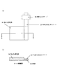
- FIG. 1 (a) schematically shows the compression process, and since this compresses approximately the thickness of the porous body during compression, the amount of strain of the skeleton near the upper portion of the compression surface is too large. As shown in FIG. 1B, it is considered that the skeleton of the porous body is broken at the upper part of the compression surface.
- the nickel porous body can be welded itself, whereas the aluminum porous body can not be welded because the compressed portion is broken. Therefore, it is considered that the cause of the fracture is that the aluminum porous body is inferior to the nickel porous body in the strength of the material itself (the strength of nickel is about 5 times that of aluminum). Therefore, as a result of diligent study, the present inventors have found that the above problem can be solved by reducing the amount of skeletal distortion near the upper part of the compression surface when compressing the end of the porous aluminum body. Completed the invention.
- the present invention relates to an electrode current collector in which the amount of distortion of the skeleton of the compression part is reduced when forming an end compression part for tab lead welding in a porous aluminum body used as an electrode current collector of a secondary battery, and a method for manufacturing the same
- the purpose is to provide.
- the configuration of the present invention is as follows.
- the electrode current collector of the present invention can weld the tab lead satisfactorily without breaking the end compression part even when stress is applied when the tab lead is welded to the end compression part.
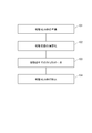
- FIG. 8 is a flowchart showing the manufacturing process of the aluminum structure.
- FIG. 9 schematically shows a state in which an aluminum plating film is formed using a resin molded body as a core material corresponding to the flowchart. The flow of the entire manufacturing process will be described with reference to both drawings.
- preparation 101 of a resin molded body to be a base is performed.
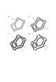
- FIG. 9A is an enlarged schematic view in which the surface of a resin molded body having continuous air holes is enlarged as an example of a resin molded body serving as a base. The pores are formed with the resin molded body 1 as a skeleton.
- the surface 102 of the resin molded body is made conductive.
- a thin conductive layer 2 is formed on the surface of the resin molded body 1 as shown in FIG. 9B.
- aluminum plating 103 in molten salt is performed to form an aluminum plating layer 3 on the surface of the resin molded body on which the conductive layer is formed (FIG. 9C).
- an aluminum structure in which the aluminum plating layer 3 is formed on the surface using the resin molded body as a base material is obtained.
- removal 104 of the resin molded body is performed for the resin molded body that is the base.
- An aluminum structure (porous body) in which only the metal layer remains can be obtained by dissociating and disappearing the resin molded body 1 (FIG. 9D).
- each step will be described in order.
- a porous resin molded body having a three-dimensional network structure and continuous air holes is prepared.
- Arbitrary resin can be selected as a raw material of a porous resin molding.
- the material include foamed resin moldings such as polyurethane, melamine, polypropylene, and polyethylene.
- foamed resin moldings such as polyurethane, melamine, polypropylene, and polyethylene.
- a resin molded article having an arbitrary shape can be selected as long as it has continuous pores (continuous vent holes). For example, what has a shape like a nonwoven fabric entangled with a fibrous resin can be used instead of the foamed resin molded article.
- the foamed resin molded article preferably has a porosity of 80% to 98% and a pore diameter of 50 ⁇ m to 500 ⁇ m.
- Foamed urethane and foamed melamine can be preferably used as a foamed resin molded article because they have high porosity, have pore connectivity and are excellent in thermal decomposability.
- Urethane foam is preferable in terms of pore uniformity and availability, and urethane foam is preferable in that a material having a small pore diameter can be obtained.
- the porous resin molded body often has residues such as foaming agents and unreacted monomers in the foam production process, and it is preferable to perform a washing treatment for the subsequent steps.
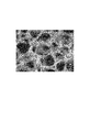
- FIG. 10 shows a product obtained by washing urethane foam as a pretreatment.
- the resin molded body forms a three-dimensional network as a skeleton, thereby forming continuous pores as a whole.
- the urethane skeleton has a substantially triangular shape in a cross section perpendicular to the extending direction.
- the porosity is defined by the following equation.
- Porosity (1- (weight of porous material [g] / (volume of porous material [cm 3 ] ⁇ material density)) ) X 100 [%]
- the surface of the foamed resin is subjected to a conductive treatment in advance.
- a conductive treatment can provide a conductive layer on the surface of the resin molded body, electroless plating of a conductive metal such as nickel, vapor deposition and sputtering of aluminum, or conductive particles such as carbon.
- coating of the conductive paint containing this, can be selected.
- the conductive treatment a method of conducting the conductive treatment by sputtering of aluminum and a method of conducting the conductive treatment of the surface of the foamed resin using carbon as conductive particles will be described below.
- the sputtering treatment using aluminum is not limited as long as aluminum is the target, and may be performed according to a conventional method. For example, after attaching a foamed resin to the substrate holder, while applying an inert gas, a DC voltage is applied between the holder and the target (aluminum) to cause the ionized inert gas to collide with the aluminum. The aluminum particles sputtered off are deposited on the foamed resin surface to form an aluminum sputtered film.
- the sputtering process is preferably performed at a temperature at which the foamed resin does not dissolve. Specifically, the sputtering process may be performed at about 100 to 200 ° C., preferably about 120 to 180 ° C.
- the suspension as the conductive paint preferably contains carbon particles, a binder, a dispersant and a dispersion medium.
- the suspension In order to uniformly apply the conductive particles, the suspension needs to maintain a uniform suspension state. For this reason, the suspension is preferably maintained at 20 ° C. to 40 ° C. The reason is that when the temperature of the suspension is lower than 20 ° C., the uniform suspension state is lost, and only the binder is concentrated on the surface of the skeleton forming the network structure of the resin molded body to form a layer. Because. In this case, the applied carbon particle layer is easy to peel off, and it is difficult to form a metal plating that is firmly adhered.
- the particle size of the carbon particles is 0.01 to 5 ⁇ m, preferably 0.01 to 0.5 ⁇ m. If the particle size is large, the pores of the resin molded body are clogged or smooth plating is hindered. If it is too small, it is difficult to ensure sufficient conductivity.
- FIG. 11 is a diagram schematically showing an example of the configuration of a processing apparatus for conducting a band-shaped resin molded body serving as a skeleton as an example of a practical manufacturing process.
- this apparatus includes a supply bobbin 12 for supplying a belt-shaped resin 11, a tank 15 containing a conductive paint suspension 14, a pair of squeezing rolls 17 disposed above the tank 15, A plurality of hot air nozzles 16 provided to face the side of the belt-shaped resin 11 to be wound, and a winding bobbin 18 that winds up the belt-shaped resin 11 after processing.
- a deflector roll 13 for guiding the belt-shaped resin 11 is appropriately disposed.
- the strip-shaped resin 1 having a three-dimensional network structure is unwound from the supply bobbin 12, guided by the deflector roll 13, and immersed in the suspension in the tank 15.
- the strip-shaped resin 11 immersed in the suspension 14 in the tank 15 changes its direction upward and travels between the squeeze rolls 17 above the liquid level of the suspension 14. At this time, the distance between the squeezing rolls 17 is smaller than the thickness of the belt-shaped resin 11, and the belt-shaped resin 11 is compressed. Therefore, the excess suspension impregnated in the belt-shaped resin 11 is squeezed out and returned to the tank 15.
- the strip-shaped resin 11 changes the traveling direction again.
- the suspension dispersion medium and the like are removed by hot air jetted by the hot air nozzle 16 composed of a plurality of nozzles, and the belt-like resin 11 is wound around the winding bobbin 18 after sufficiently drying.
- the temperature of the hot air ejected from the hot air nozzle 16 is preferably in the range of 40 ° C to 80 ° C.
- Formation of aluminum layer molten salt plating
- electrolytic plating is performed in a molten salt to form an aluminum plating layer on the surface of the resin molded body.
- a uniformly thick aluminum layer can be formed on the surface of a complicated skeleton structure, particularly a resin molded body having a three-dimensional network structure.
- a direct current is applied in a molten salt using a resin molded body having a conductive surface as a cathode and aluminum as an anode.
- an organic molten salt that is a eutectic salt of an organic halide and an aluminum halide, or an inorganic molten salt that is a eutectic salt of an alkali metal halide and an aluminum halide can be used.
- Use of an organic molten salt bath that melts at a relatively low temperature is preferable because plating can be performed without decomposing the resin molded body as a base material.
- the organic halide imidazolium salt, pyridinium salt and the like can be used, and specifically, 1-ethyl-3-methylimidazolium chloride (EMIC) and butylpyridinium chloride (BPC) are preferable. Since the molten salt deteriorates when moisture or oxygen is mixed in the molten salt, the plating is preferably performed in an atmosphere of an inert gas such as nitrogen or argon and in a sealed environment.
- an inert gas such as nitrogen or argon
- a molten salt bath containing nitrogen is preferable, and among them, an imidazolium salt bath is preferably used.
- an imidazolium salt bath is preferably used.
- a salt that melts at a high temperature is used as the molten salt, the resin is dissolved or decomposed in the molten salt faster than the growth of the plating layer, and the plating layer cannot be formed on the surface of the resin molded body.
- the imidazolium salt bath can be used without affecting the resin even at a relatively low temperature.
- a salt containing an imidazolium cation having an alkyl group at the 1,3-position is preferably used.
- an aluminum chloride-1-ethyl-3-methylimidazolium chloride (AlCl 3 -EMIC) -based molten salt is used. It is most preferably used because it is highly stable and hardly decomposes. Plating onto foamed urethane resin or foamed melamine resin is possible, and the temperature of the molten salt bath is 10 ° C to 65 ° C, preferably 25 ° C to 60 ° C. The lower the temperature, the narrower the current density range that can be plated, and the more difficult it is to plate on the entire porous body surface. At a high temperature exceeding 65 ° C., a problem that the shape of the base resin is impaired tends to occur.
- AlCl 3 -EMIC aluminum chloride-1-ethyl-3-methylimidazolium chloride
- an organic solvent to the molten salt bath, and 1,10-phenanthroline is particularly preferably used.
- the amount added to the plating bath is preferably 0.2 to 7 g / L. If it is 0.2 g / L or less, it is brittle with plating having poor smoothness, and it is difficult to obtain the effect of reducing the difference in thickness between the surface layer and the inside. On the other hand, if it is 7 g / L or more, the plating efficiency is lowered and it is difficult to obtain a predetermined plating thickness.
- FIG. 12 is a diagram schematically showing a configuration of an apparatus for continuously performing the aluminum plating process on the above-described belt-shaped resin.
- a configuration in which the belt-like resin 22 whose surface is made conductive is sent from the left to the right in the figure.
- the first plating tank 21a includes a cylindrical electrode 24, an anode 25 made of aluminum provided on the inner wall of the container, and a plating bath 23. By passing the strip-shaped resin 22 through the plating bath 23 along the cylindrical electrode 24, a uniform current can easily flow through the entire resin molded body, and uniform plating can be obtained.
- the plating tank 21b is a tank for applying a thick and uniform plating, and is configured to be repeatedly plated in a plurality of tanks.
- Plating is performed by passing the belt-like resin 22 having a conductive surface through a plating bath 28 while sequentially feeding the belt-like resin 22 by an electrode roller 26 that also serves as a feeding roller and an out-of-vessel feeding cathode.
- anodes 27 made of aluminum provided on both surfaces of the resin molded body via a plating bath 28, and uniform plating can be applied to both surfaces of the resin molded body. After sufficiently removing the plating solution from the plated aluminum porous body by nitrogen blowing, the aluminum porous body can be obtained by washing with water.
- an inorganic salt bath can be used as the molten salt as long as the resin is not dissolved.
- the inorganic salt bath is typically a binary or multicomponent salt of AlCl 3 —XCl (X: alkali metal).
- Such an inorganic salt bath generally has a higher melting temperature than an organic salt bath such as an imidazolium salt bath, but is less restricted by environmental conditions such as moisture and oxygen, and can be put into practical use at a low cost overall.
- the resin is a foamed melamine resin, it can be used at a higher temperature than the foamed urethane resin, and an inorganic salt bath at 60 ° C. to 150 ° C. is used.
- an aluminum structure (aluminum porous body) having a resin molded body as a skeleton core is obtained.
- the resin and metal composite may be used as they are.
- the resin may be removed when used as a metal structure having no resin due to restrictions on the use environment. Removal of the resin can be performed by any method such as decomposition (dissolution) with an organic solvent, molten salt, or supercritical water, and thermal decomposition.
- methods such as thermal decomposition at high temperatures are simple, but involve oxidation of aluminum. Unlike nickel and the like, aluminum is difficult to reduce once oxidized.
- Thermal decomposition in the molten salt is performed by the following method.
- a resin molded body having an aluminum plating layer formed on the surface is immersed in a molten salt and heated while applying a negative potential to the aluminum layer to decompose the foamed resin molded body.
- a negative potential is applied while being immersed in the molten salt, the foamed resin molded product can be decomposed without oxidizing aluminum.
- heating temperature can be suitably selected according to the kind of foaming resin molding, in order not to melt aluminum, it is necessary to process at the temperature below melting
- a preferable temperature range is 500 ° C. or more and 600 ° C. or less.
- the amount of negative potential to be applied is on the minus side of the reduction potential of aluminum and on the plus side of the reduction potential of cations in the molten salt.
- the porous aluminum body has a three-dimensional porous structure (high specific surface area), it has a structure for holding the battery material, and can form a thick and large-capacity electrode, reducing the electrode area and reducing the cost. Can be Moreover, the usage-amount of an extra binder and a conductive support agent can be reduced, and a battery can be increased in capacity. Since the porous aluminum body has good contact with the battery material, it can increase the output of the battery, prevent the battery material from falling off, and extend the life of the battery or capacitor. Thus, the LIB, capacitor, molten salt battery, etc. It can be used for electrode current collector applications.
- the porous aluminum body has a three-dimensional porous structure (high specific surface area), and when this is used as a heater, kerosene can be heated and vaporized efficiently, so a kerosene vaporizer or atomizer It can be used as a heating equipment application.
- Radioactive contaminated water filtration filter Aluminum is used as a material to prevent radioactivity leakage because it has the property of blocking radioactivity. At present, the removal of radioactivity from contaminated water generated from nuclear power plants is an issue, but the aluminum foil used as a radioactive leak prevention material does not allow water to pass through, so the radioactivity of contaminated water cannot be removed. . On the other hand, since the porous aluminum body has a three-dimensional porous structure (high specific surface area), it can transmit water and can be used as a purification filter for radioactively contaminated water. Furthermore, the filtration of impurities can be strengthened by forming a double-structured film of poreflon (registered trademark: polytetrafluoroethylene (PTFE) porous body) and an aluminum porous body.
- poreflon registered trademark: polytetrafluoroethylene (PTFE) porous body
- the porous aluminum body has a three-dimensional porous structure (high specific surface area), so it has a large sound absorption effect, and since the material is aluminum and lightweight, it can be used as a silencer for engines and pneumatic equipment, or as a sound absorber for pantographs. It can be used for sound reduction applications.
- Electromagnetic shielding shield room, various shields Since the porous aluminum body has a continuous air hole structure (high air permeability), it has better air permeability than a sheet-like electromagnetic shielding material, and the hole diameter can be freely selected so that it can be used in various frequency bands. Since it can respond
- Heat dissipation and heat exchange (heat exchanger, heat sink)
- Aluminum porous body has a three-dimensional porous structure (large specific surface area), and since the material is aluminum and has high thermal conductivity, it has a large heat dissipation effect, so heat dissipation and heat exchange of heat exchangers, heat sinks, etc. Can be used for applications.
- Fuel cells Currently, carbon paper is mainly used for gas diffusion current collectors and separators of polymer electrolyte fuel cells, but this is expensive and requires complicated flow path formation. Therefore, there is a problem that the production cost is increased.
- the porous aluminum body has the characteristics of a three-dimensional porous structure, low resistance, and a passive film on the surface, a high potential and acidic atmosphere in the fuel cell can be obtained without forming a complicated flow path.
- Can be used as a gas diffusion layer / current collector and separator and as a result, the cost can be reduced, so that it can be used for fuel cell applications such as a gas diffusion layer / current collector and separator of a polymer electrolyte fuel cell. Can be used.
- aluminum porous bodies with closed pores are sometimes used to reduce weight. Since the aluminum porous body has a three-dimensional porous structure (high porosity), it can be further reduced in weight than the aluminum porous body having closed pores. In addition, since it is a continuous ventilation hole, other materials such as resin can be filled in the space, and when combined with a material with functions such as heat insulation, sound insulation, humidity control, etc., it is not possible with conventional porous aluminum porous body A composite material having a certain function can be obtained.
- Electromagnetic induction heating It is said that earthenware pots are preferred when pursuing deliciousness in cooking utensils.
- IH heating allows fine heat control. Taking advantage of both characteristics, there is a demand for a clay pot that can be heated by IH. Conventionally, methods such as arranging a magnetic material on the bottom of a clay pot or using special soil have been proposed, but none of them has a sufficient heat conduction and does not make full use of the features of IH heating.
- an earthen pot is formed by using an aluminum porous body as a core material, kneading soil into the core material, and sintering it in an inert gas atmosphere, the aluminum porous body serving as the core material generates heat, and thus uniform. Heating is possible.
- an aluminum porous body is preferred in view of weight reduction.
- the end of the aluminum porous body is compressed by the following methods (1) to (3). Thereby, even in an aluminum porous body having a low mechanical strength, a strength sufficient to allow tab lead welding is obtained.
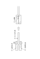
- (1) Method of compressing end of aluminum porous body from both sides with compression jig As shown in FIG. 2, the end of aluminum porous body is compressed from both sides in the thickness direction by using compression jigs 32 and 32 '.
- the amount of strain on the skeleton of the porous body can be reduced, and the number of porous skeletons that are not broken can be increased, so the strength of the boundary between the compressed portion and the uncompressed portion of the porous body can be increased.
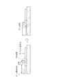
- the front and back surfaces of the porous aluminum body according to the pressing method of the present invention shown in FIG. 2 are compared with the case where L is the amount of deformation in the thickness direction when compression from one surface is performed.
- the amount of deformation in each is L / 2
- the amount of distortion of the skeleton of the porous body is halved, the number of unbroken skeletons can be increased, and the strength of the boundary between the compressed part and the uncompressed part of the porous body is enhanced. It becomes possible to do.
- the radius of curvature of R is not particularly limited as long as the corners of the compression jig are rounded, but the radius of curvature is preferably 0.1 mm to 5.0 mm, more preferably 0.2 mm. ⁇ 3.0 mm.
- this method is the method of (1) and the method of (2).
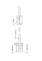
- the number of porous body skeletons that are not broken can be further increased, and the strength of the boundary between the compressed portion and the uncompressed portion of the porous body can be further enhanced.
- a plurality of belt-like compression portions are formed in the central portion of the porous aluminum body using a plurality of sets of rotating rollers, and each of the belt-like compression portions is cut along a center line in the surface direction. Individual current collectors can be obtained.
- a tab lead is joined to the end compression part of the current collector obtained as described above.
- the tab lead it is preferable to use a metal foil to reduce the electric resistance of the electrode and to bond the metal foil to the surface on at least one side of the peripheral edge of the electrode.
- welding it is preferable to use welding as a joining method. If the width of the metal foil to be welded is too large, useless space increases in the battery and the capacity density of the battery decreases, so that it is preferably 10 mm or less. If it is too thin, welding becomes difficult and the current collecting effect is lowered, so 1 mm or more is preferable.
- Metal foil As a material of the metal foil, aluminum is preferable in consideration of electric resistance and resistance to an electrolytic solution. In addition, since impurities are eluted and reacted in the battery and the capacitor, it is preferable to use an aluminum foil having a purity of 99.99% or more. Moreover, it is preferable that the thickness of a welding part is thinner than the thickness of electrode itself. The thickness of the aluminum foil is preferably 20 to 500 ⁇ m.
- the metal foil may be welded either before or after the current collector is filled with the active material, but the active material can be prevented from falling off before being filled. In particular, in the case of ultrasonic welding, it is preferable to perform welding before filling. Moreover, although activated carbon paste may be attached to the welded portion, it may be peeled off during the process, so it is preferable to mask it so that it cannot be filled.
- Electrodes Fill the adjusted current collector with activated carbon paste. It can also be filled by spraying a paste from one side of the current collector, immersing the current collector in the paste, or using a printing machine or a roll coater. Next, the solvent is removed with a dryer. The drying temperature is preferably 80 ° C. or higher. However, if the temperature is too high, oxidation of the current collector or decomposition of the thickener or binder may occur. After drying, the electrode is obtained by compressing in the thickness direction with a press. As the press machine, a flat plate press or a roller press can be used.
- a flat plate press is preferable for suppressing the elongation of the current collector, but is not suitable for mass production, and a roller press capable of continuous processing can also be used.
- a roller press When a roller press is used, it may be devised to suppress elongation such as embossing the surface.
- the electrolyte used for the lithium battery includes a non-aqueous electrolyte and a solid electrolyte.
- FIG. 13 is a longitudinal sectional view of an all-solid lithium battery using a solid electrolyte.
- the all solid lithium battery 60 includes a positive electrode 61, a negative electrode 62, and a solid electrolyte layer (SE layer) 63 disposed between both electrodes.
- the positive electrode 61 includes a positive electrode layer (positive electrode body) 64 and a positive electrode current collector 65
- the negative electrode 62 includes a negative electrode layer 66 and a negative electrode current collector 67.
- a non-aqueous electrolyte described later is used as the electrolyte.
- a separator such as a porous polymer film
- the non-aqueous electrolyte is impregnated in both electrodes and the separator.
- an aluminum porous body When an aluminum porous body is used for a positive electrode of a lithium battery, a material capable of removing and inserting lithium can be used as an active material, and it is suitable for a lithium secondary battery by filling such an aluminum porous body. An electrode can be obtained.
- the material for the positive electrode active material include lithium cobaltate (LiCoO 2 ), lithium nickelate (LiNiO 2 ), lithium nickel cobaltate (LiCo 0.3 Ni 0.7 O 2 ), lithium manganate (LiMn 2 O 4 ), and titanate.
- the active material is used in combination with a conductive additive and a binder.
- transition metal oxides such as olivine compounds which are conventional lithium iron phosphate and its compounds (LiFePO 4 , LiFe 0.5 Mn 0.5 PO 4 ). Further, the transition metal element contained in these materials may be partially substituted with another transition metal element.
- Still other positive electrode active materials include, for example, TiS 2 , V 2 S 3 , FeS, FeS 2 , LiMSx (M is a transition metal element such as Mo, Ti, Cu, Ni, Fe, or Sb, Sn, Pb) ) And the like, and lithium metal having a skeleton of a metal oxide such as TiO 2 , Cr 3 O 8 , V 2 O 5 , and MnO 2 .
- the lithium titanate obtained by the ((Li 4 Ti 5 O 12 ) it is also possible to use as a negative electrode active material.
- Non-aqueous electrolyte a polar aprotic organic solvent is used, and specifically, ethylene carbonate, diethyl carbonate, dimethyl carbonate, propylene carbonate, ⁇ -butyrolactone, sulfolane and the like are used.
- the supporting salt lithium tetrafluoroborate, lithium hexafluorophosphate, and an imide salt are used.
- Solid electrolyte filled in aluminum porous body In addition to the active material, a solid electrolyte may be added and filled. By filling an aluminum porous body with an active material and a solid electrolyte, it can be made suitable for an electrode of an all-solid-state lithium battery.
- the proportion of the active material in the material filled in the aluminum porous body is preferably 50% by mass or more, more preferably 70% by mass or more, from the viewpoint of securing the discharge capacity.
- a sulfide-based solid electrolyte having high lithium ion conductivity is preferably used.
- a sulfide-based solid electrolyte having high lithium ion conductivity examples include a sulfide-based solid electrolyte containing lithium, phosphorus, and sulfur. It is done.
- the sulfide solid electrolyte may further contain an element such as O, Al, B, Si, and Ge.
- Such a sulfide-based solid electrolyte can be obtained by a known method.
- lithium sulfide (Li 2 S) and diphosphorus pentasulfide (P 2 S 5 ) are prepared as starting materials, and the ratio of Li 2 S and P 2 S 5 is about 50:50 to 80:20 in molar ratio.
- a method of melting and quenching the mixture melting and quenching method
- a method of mechanically milling the mixture (nocical milling method).
- the sulfide-based solid electrolyte obtained by the above method is amorphous. Although it can be used in this amorphous state, it may be heat-treated to obtain a crystalline sulfide solid electrolyte. Crystallization can be expected to improve lithium ion conductivity.
- the active material for filling the active material (the active material and the solid electrolyte)
- a known method such as an immersion filling method or a coating method
- the coating method include roll coating method, applicator coating method, electrostatic coating method, powder coating method, spray coating method, spray coater coating method, bar coater coating method, roll coater coating method, dip coater coating method, doctor Examples thereof include a blade coating method, a wire bar coating method, a knife coater coating method, a blade coating method, and a screen printing method.
- a conductive additive or binder is added, and an organic solvent is mixed therewith to produce a positive electrode mixture slurry, Used to fill the aluminum porous body.
- the filling of the active material (the active material and the solid electrolyte) is preferably performed in an inert gas atmosphere in order to prevent oxidation of the aluminum porous body.
- carbon black such as acetylene black (AB) or ketjen black (KB) can be used as the conductive assistant
- examples of the binder include polyvinylidene fluoride (PVDF) and polytetrafluoroethylene (PV). PTFE) or the like can be used.
- the organic solvent used when preparing the positive electrode mixture slurry has an adverse effect on the material (that is, the active material, the conductive additive, the binder, and, if necessary, the solid electrolyte) filled in the aluminum porous body. If not, it can be selected as appropriate.
- organic solvents include n-hexane, cyclohexane, heptane, toluene, xylene, trimethylbenzene, dimethyl carbonate, diethyl carbonate, ethyl methyl carbonate, propylene carbonate, ethylene carbonate, butylene carbonate, vinylene carbonate, vinyl ethylene carbonate. , Tetrahydrofuran, 1,4-dioxane, 1,3-dioxolane, ethylene glycol, N-methyl-2-pyrrolidone and the like.
- the conventional positive electrode material for ion batteries has applied the active material to the surface of aluminum foil.
- the coating thickness of the active material is increased.
- the aluminum foil and the active material need to be in electrical contact with each other, so that the active material is used in combination with a conductive additive.
- the porous aluminum body has a high porosity and a large surface area per unit area. Therefore, even if the active material is thinly supported on the surface of the porous body, the active material can be used effectively, the capacity of the battery can be improved, and the mixing amount of the conductive auxiliary agent can be reduced.
- a lithium battery uses the above positive electrode material as the positive electrode, graphite as the negative electrode, and organic electrolyte as the electrolyte. Since such a lithium battery can improve capacity even with a small electrode area, the energy density of the battery can be made higher than that of a conventional lithium battery.
- FIG. 14 is a schematic cross-sectional view showing an example of a capacitor using a capacitor electrode material.
- an electrode material in which an electrode active material is supported on a porous aluminum body is disposed as a polarizable electrode 141.
- the polarizable electrode 141 is connected to the lead wire 144 and is entirely housed in the case 145.
- activated carbon is used as an active material for the current collector.
- Activated carbon is used in combination with a conductive additive or binder.
- a conductive additive or binder As the conductive auxiliary agent, graphite, carbon nanotube, etc. can be used.
- the binder polytetrafluoroethylene (PTFE), styrene butadiene rubber or the like can be used. Fill with activated carbon paste.
- the amount of activated carbon as a main component is larger, and the activated carbon is preferably 90% or more in terms of the composition ratio after drying (after solvent removal).
- a conductive auxiliary agent and a binder are necessary, it is a factor of a capacity
- the conductive auxiliary agent is preferably 10% by mass or less, and the binder is preferably 10% by mass or less.
- An activated carbon paste can be obtained by mixing and stirring the electrode material mainly composed of activated carbon.
- the activated carbon paste is filled in the current collector and dried, and the electrode for a capacitor is obtained by adjusting the thickness with a roller press or the like as necessary.
- Capacitor production Two of the electrodes obtained as described above are punched out to a suitable size, and are opposed to each other with a separator interposed therebetween. And it accommodates in a cell case using a required spacer, and impregnates electrolyte solution. Finally, the case using a non-aqueous electrolyte can be manufactured by sealing the case with an insulating gasket. When a non-aqueous material is used, in order to reduce the moisture in the capacitor as much as possible, the capacitor is manufactured in an environment with little moisture, and the sealing is performed in a reduced pressure environment.
- the capacitor is not particularly limited as long as the current collector and electrode of the present invention are used, and the capacitor may be manufactured by other methods.
- the negative electrode is not particularly limited, and a conventional negative electrode can be used. However, since the capacity of the conventional electrode using an aluminum foil as a current collector is small, the negative electrode can be used for a porous material such as the aforementioned foamed nickel. An electrode filled with a substance is preferred.
- Electrolyte can be used for both aqueous and non-aqueous, but non-aqueous is preferable because the voltage can be set higher.
- potassium hydroxide or the like can be used as an electrolyte.
- non-aqueous systems there are many ionic liquids in combination of cations and anions.
- cation lower aliphatic quaternary ammonium, lower aliphatic quaternary phosphonium, imidazolinium and the like are used, and as the anion, imide compounds such as metal chloride ion, metal fluoride ion, and bis (fluorosulfonyl) imide Etc. are known.
- a polar aprotic organic solvent specifically, ethylene carbonate, diethyl carbonate, dimethyl carbonate, propylene carbonate, ⁇ -butyrolactone, sulfolane and the like are used.
- the supporting salt in the nonaqueous electrolytic solution lithium tetrafluoroborate, lithium hexafluorophosphate, and an imide salt are used.
- the aluminum porous body can also be used as an electrode material for a molten salt battery.
- the porous aluminum as a positive electrode material include sodium chromite as the active material (NaCrO2), titanium disulfide (TiS 2) or the like, a metal compound cation of the molten salt as the electrolyte can be intercalated use.
- the active material is used in combination with a conductive additive and a binder.
- acetylene black or the like can be used.
- As the binder polytetrafluoroethylene (PTFE) or the like can be used. When sodium chromate is used as the active material and acetylene black is used as the conductive aid, PTFE is preferable because both can be firmly fixed.
- the aluminum porous body can also be used as a negative electrode material for a molten salt battery.
- an aluminum porous body is used as a negative electrode material
- sodium alone, an alloy of sodium and another metal, carbon, or the like can be used as an active material.
- the melting point of sodium is about 98 ° C., and the metal softens as the temperature rises. Therefore, it is preferable to alloy sodium with other metals (Si, Sn, In, etc.). Of these, an alloy of sodium and Sn is particularly preferable because it is easy to handle.
- Sodium or a sodium alloy can be supported on the surface of the porous aluminum body by a method such as electrolytic plating or hot dipping.
- a metal (such as Si) that is alloyed with sodium is attached to the aluminum porous body by a method such as plating, a sodium alloy can be obtained by charging in a molten salt battery.
- FIG. 15 is a schematic cross-sectional view showing an example of a molten salt battery using the above-described battery electrode material.
- the molten salt battery includes a positive electrode 121 carrying a positive electrode active material on the surface of an aluminum skeleton part of an aluminum porous body, a negative electrode 122 carrying a negative electrode active material on the surface of the aluminum skeleton part of an aluminum porous body, and an electrolyte.
- a separator 123 impregnated with molten salt is housed in a case 127. Between the upper surface of the case 127 and the negative electrode, a pressing member 126 including a pressing plate 124 and a spring 125 that presses the pressing plate is disposed.
- the current collector (aluminum porous body) of the positive electrode 121 and the current collector (aluminum porous body) of the negative electrode 122 are connected to the positive electrode terminal 128 and the negative electrode terminal 129 by lead wires 130, respectively.
- molten salt As the electrolyte, various inorganic salts or organic salts that melt at the operating temperature can be used.
- alkali metals such as lithium (Li), sodium (Na), potassium (K), rubidium (Rb) and cesium (Cs), beryllium (Be), magnesium (Mg), calcium (Ca)
- strontium (Sr) and barium (Ba) can be used.
- the operating temperature can be 90 ° C. or lower.
- a separator is for preventing a positive electrode and a negative electrode from contacting, and a glass nonwoven fabric, a porous resin molding, etc. can be used.
- the above positive electrode, negative electrode, and separator impregnated with molten salt are stacked and housed in a case to be used as a battery.
- Example 1 (Formation of conductive layer) As a urethane resin molded body, a urethane foam having a porosity of 95%, the number of pores per one inch (number of cells), a pore diameter of about 550 ⁇ m, and a thickness of 1 mm was prepared and cut into a 100 mm ⁇ 30 mm square. . A conductive layer was formed on the surface of the polyurethane foam by sputtering to form aluminum with a basis weight of 10 g / m 2 .
- a urethane foam with a conductive layer formed on the surface is set as a work piece in a jig with a power supply function, and then placed in a glove box with an argon atmosphere and low moisture (dew point -30 ° C or less), and melted at a temperature of 40 ° C. It was immersed in a salt aluminum plating bath (33 mol% EMIC-67 mol% AlCl 3 ). The jig on which the workpiece was set was connected to the cathode side of the rectifier, and a counter electrode aluminum plate (purity 99.99%) was connected to the anode side.
- An aluminum structure in which an aluminum plating layer having a weight of 150 g / m 2 was formed on the surface of the urethane foam was obtained by plating by applying a direct current of a current density of 3.6 A / dm 2 for 90 minutes. Stirring was performed with a stirrer using a Teflon (registered trademark) rotor.
- the current density is a value calculated by the apparent area of the urethane foam.
- the aluminum structure was immersed in a LiCl—KCl eutectic molten salt at a temperature of 500 ° C., and a negative potential of ⁇ 1 V was applied for 30 minutes. Bubbles were generated in the molten salt due to the decomposition reaction of the polyurethane. Then, after cooling to room temperature in the atmosphere, the molten salt was removed by washing with water to obtain a porous aluminum body from which the resin was removed. The obtained aluminum porous body had continuous air holes, and the porosity was as high as the urethane foam used as the core material.
- the obtained aluminum porous body was adjusted to a thickness of 1.0 mm by a roller press and cut into 1.5 cm square.
- a 5 mm wide SUS block (bar) and a hammer as a compression jig, sandwich a 5 mm portion from one end of the porous aluminum body with SUS blocks from both sides, and hit the SUS block with a hammer.
- a compressed portion having a thickness of 100 ⁇ m was formed by compression.
- the tab lead was welded by spot welding under the following conditions.
- FIG. 1 A schematic view of the porous aluminum body obtained in FIG. 6 is shown in FIG. A tab lead 37 is welded to the compressed portion 33 of the aluminum porous body 34.
- FIG. 6B is a cross-sectional view taken along the line AA in FIG. The number of fractures of the skeleton at the boundary line portion between the compressed portion and the uncompressed portion was 1.4 / mm.
- Example 2 In Example 1, using an SUS block with an radius of curvature of 0.5 mm at the end of the SUS block, the aluminum porous body was placed on the base and the aluminum porous body was placed on the 5 mm portion from the end of one side. Except for hitting with a hammer through a SUS block, a porous aluminum body in which a tab lead was spot-welded to the end compression portion was obtained in the same manner as in Example 1. When the number of fractures of the skeleton at the boundary line portion between the compressed portion and the uncompressed portion was counted, it was 1.5 pieces / mm.
- Example 3 In Example 1, an aluminum porous body was placed on a base and used from the end of one side of the aluminum porous body, except that an SUS block having a radius of curvature of 0.5 mm was used at the end of the SUS block. A porous aluminum body in which a tab lead was spot welded to the end compression portion was obtained in the same manner as in Example 1 except that the 5 mm portion was hit with a hammer through the SUS block. When the number of fractures of the skeleton at the boundary line portion between the compressed portion and the uncompressed portion was counted, it was 1.0 piece / mm.
- Example 2 In Example 2, except that an SUS block having no R at the end of the SUS block was used, the porous aluminum body was placed on the base, and the SUS block was placed 5 mm from the edge of one side of the porous aluminum body. A porous aluminum body was obtained in the same manner as in Example 1 except that the tab lead was spot-welded to the end compression portion, except that it was hit with a hammer. When the number of fractures of the skeleton at the boundary line portion between the compressed portion and the uncompressed portion was counted, it was 3.8 pieces / mm.
- the aluminum porous body for a current collector of the present invention has a small number of fractures of the skeleton of the end compression portion for tab lead welding, the end lead compression portion does not break even if stress is applied during welding of the tab lead. Since it can be welded well, it can be suitably used as an electrode current collector of a secondary battery or the like.
Landscapes
- Engineering & Computer Science (AREA)
- Chemical & Material Sciences (AREA)
- Power Engineering (AREA)
- Chemical Kinetics & Catalysis (AREA)
- Electrochemistry (AREA)
- General Chemical & Material Sciences (AREA)
- Microelectronics & Electronic Packaging (AREA)
- Materials Engineering (AREA)
- Manufacturing & Machinery (AREA)
- Cell Electrode Carriers And Collectors (AREA)
- Electric Double-Layer Capacitors Or The Like (AREA)
- Fuel Cell (AREA)
- Hydroponics (AREA)
- Filtering Materials (AREA)
- Catalysts (AREA)
- Inert Electrodes (AREA)
Abstract
Description
この方法によれば、2~20μmの厚さのアルミニウム多孔体が得られるとされているが、気相法によるため大面積での製造は困難であり、基体の厚さや気孔率によっては内部まで均一な層の形成が難しい。またアルミニウム層の形成速度が遅い、設備が高価などにより製造コストが増大するなどの問題点がある。さらに、厚膜を形成する場合には、膜に亀裂が生じたりアルミニウムの脱落が生じたりするおそれがある。
しかしながら、この方法によればアルミニウムと共晶合金を形成する層が出来てしまい、純度の高いアルミニウム層が形成できない。
しかしながら、アルミニウムの電気めっきについては金属表面へのめっきが可能であるのみで、樹脂成形体表面への電気めっき、とりわけ三次元網目構造を有する樹脂成形体の表面に電気めっきする方法は知られていなかった。
樹脂の除去は、有機溶媒、溶融塩、又は超臨界水による分解(溶解)、加熱分解等任意の方法で行うことができる。
ここで、高温での加熱分解等の方法は簡便であるが、アルミニウムの酸化を伴う。アルミニウムはニッケル等と異なり、一旦酸化すると還元処理が困難であるため、たとえば電池等の電極材料として使用する場合には、酸化により導電性が失われることから用いることが出来ない。そこで、本発明者等はアルミニウムの酸化が起こらないようにして樹脂を除去する方法として、多孔質樹脂成形体の表面にアルミニウム層を形成してなるアルミニウム構造体を溶融塩に浸漬した状態で、該アルミニウム層に負電位を印加しながらアルミニウムの融点以下の温度に加熱して多孔質樹脂成形体を熱分解して除去することによってアルミニウム多孔体を製造する方法を完成した。
そこで、本発明者等は鋭意検討を進めた結果、アルミニウム多孔体の端部を圧縮する際に、圧縮面上部付近の骨格の歪量を小さくすることにより上記の問題が解決できることを見出して本発明を完成した。
本発明は、二次電池の電極集電体として用いられるアルミニウム多孔体にタブリード溶接用の端部圧縮部を形成するに際し、圧縮部の骨格の歪み量を小さくした電極集電体及びその製造方法を提供することを目的とする。
本発明の構成は以下の通りである。
図8は、アルミニウム構造体の製造工程を示すフロー図である。また図9は、フロー図に対応して樹脂成形体を芯材としてアルミニウムめっき膜を形成する様子を模式的に示したものである。両図を参照して製造工程全体の流れを説明する。まず基体となる樹脂成形体の準備101を行う。図9(a)は、基体となる樹脂成形体の例として、連通気孔を有する樹脂成形体の表面を拡大視した拡大模式図である。樹脂成形体1を骨格として気孔が形成されている。次に樹脂成形体表面の導電化102を行う。この工程により、図9(b)に示すように樹脂成形体1の表面には薄く導電体による導電層2が形成される。
続いて溶融塩中でのアルミニウムめっき103を行い、導電層が形成された樹脂成形体の表面にアルミニウムめっき層3を形成する(図9(c))。これで、樹脂成形体を基材として表面にアルミニウムめっき層3が形成されたアルミニウム構造体が得られる。基体である樹脂成形体については、樹脂成形体の除去104を行う。
樹脂成形体1を分解等して消失させることにより金属層のみが残ったアルミニウム構造体(多孔体)を得ることができる(図9(d))。以下各工程について順を追って説明する。
(多孔質樹脂成形体の準備)
三次元網目構造を有し連通気孔を有する多孔質樹脂成形体を準備する。多孔質樹脂成形体の素材は任意の樹脂を選択できる。ポリウレタン、メラミン、ポリプロピレン、ポリエチレン等の発泡樹脂成形体が素材として例示できる。発泡樹脂成形体と表記したが、連続した気孔(連通気孔)を有するものであれば任意の形状の樹脂成形体を選択できる。例えば繊維状の樹脂を絡めて不織布のような形状を有するものも発泡樹脂成形体に代えて使用可能である。発泡樹脂成形体の気孔率は80%~98%、気孔径は50μm~500μmとするのが好ましい。発泡ウレタン及び発泡メラミンは気孔率が高く、また気孔の連通性があるとともに熱分解性にも優れているため発泡樹脂成形体として好ましく使用できる。
発泡ウレタンは気孔の均一性や入手の容易さ等の点で好ましく、発泡ウレタンは気孔径の小さなものが得られる点で好ましい。
気孔率=(1-(多孔質材の重量[g]/(多孔質材の体積[cm3]×素材密度))
)×100[%]
また、気孔径は、樹脂成形体表面を顕微鏡写真等で拡大し、1インチ(25.4mm)あたりの気孔数をセル数として計数して、平均孔径=25.4mm/セル数として平均的な値を求める。
電解めっきを行うために、発泡樹脂の表面をあらかじめ導電化処理する。樹脂成形体の表面に導電性を有する層を設けることができる処理である限り特に制限はなく、ニッケル等の導電性金属の無電解めっき、アルミニウム等の蒸着及びスパッタ、又はカーボン等の導電性粒子を含有した導電性塗料の塗布等任意の方法を選択できる。
導電化処理の例として、アルミニウムのスパッタリング処理によって導電化処理する方法、及び導電性粒子としてカーボンを用いて発泡樹脂の表面を導電化処理する方法について以下述べる。
アルミニウムを用いたスパッタリング処理としては、アルミニウムをターゲットとする限り限定的でなく、常法に従って行えばよい。例えば、基板ホルダーに発泡状樹脂を取り付けた後、不活性ガスを導入しながら、ホルダーとターゲット(アルミニウム)との間に直流電圧を印加することにより、イオン化した不活性ガスをアルミニウムに衝突させて、はじき飛ばされたアルミニウム粒子を発泡状樹脂表面に堆積することによってアルミニウムのスパッタ膜を形成する。なお、スバッタリング処理は発泡状樹脂が溶解しない温度下で行うことが好ましく、具体的には、100~200℃程度、好ましくは120~180℃程度で行えばよい。
導電性塗料としてのカーボン塗料を準備する。導電性塗料としての懸濁液は、好ましくは、カーボン粒子、粘結剤、分散剤および分散媒を含む。導電性粒子の塗布を均一に行うには、懸濁液が均一な懸濁状態を維持している必要がある。このため、懸濁液は、20℃~40℃に維持されていることが好ましい。その理由は、懸濁液の温度が20℃未満になった場合、均一な懸濁状態が崩れ、樹脂成形体の網状構造をなす骨格の表面に粘結剤のみが集中して層を形成するからである。この場合、塗布されたカーボン粒子の層は剥離し易く、強固に密着した金属めっきを形成し難い。一方、懸濁液の温度が40℃を越えた場合は、分散剤の蒸発量が大きく、塗布処理時間の経過とともに懸濁液が濃縮されてカーボンの塗布量が変動しやすい。また、カーボン粒子の粒径は、0.01~5μmで、好ましくは0.01~0.5μmである。粒径が大きいと樹脂成形体の空孔を詰まらせたり、平滑なめっきを阻害する要因となり、小さすぎると十分な導電性を確保することが難しくなる。
次に溶融塩中で電解めっきを行い、樹脂成形体表面にアルミニウムめっき層を形成する。
溶融塩浴中でアルミニウムのめっきを行うことにより特に三次元網目構造を有する樹脂成形体のように複雑な骨格構造の表面に均一に厚いアルミニウム層を形成することができる。
表面が導電化された樹脂成形体を陰極とし、アルミニウムを陽極として溶融塩中で直流電流を印加する。
また、溶融塩としては、有機系ハロゲン化物とアルミニウムハロゲン化物の共晶塩である有機溶融塩、アルカリ金属のハロゲン化物とアルミニウムハロゲン化物の共晶塩である無機溶融塩を使用することができる。比較的低温で溶融する有機溶融塩浴を使用すると、基材である樹脂成形体を分解することなくめっきができ好ましい。有機系ハロゲン化物としてはイミダゾリウム塩、ピリジニウム塩等が使用でき、具体的には1-エチル-3-メチルイミダゾリウムクロライド(EMIC)、ブチルピリジニウムクロライド(BPC)が好ましい。
溶融塩中に水分や酸素が混入すると溶融塩が劣化するため、めっきは窒素、アルゴン等の不活性ガス雰囲気下で、かつ密閉した環境下で行うことが好ましい。
このため、アルミニウムの酸化が起こらないように、以下に説明する溶融塩中での熱分解により樹脂を除去する方法が好ましく用いられる。
溶融塩中での熱分解は以下の方法で行う。表面にアルミニウムめっき層を形成した樹脂成形体を溶融塩に浸漬し、アルミニウム層に負電位を印加しながら加熱して発泡樹脂成形体を分解する。溶融塩に浸漬した状態で負電位を印加すると、アルミニウムを酸化させることなく発泡樹脂成形体を分解することができる。加熱温度は発泡樹脂成形体の種類に合わせて適宜選択できるが、アルミニウムを溶融させないためにはアルミニウムの融点(660℃)以下の温度で処理する必要がある。好ましい温度範囲は500℃以上600℃以下である。また印加する負電位の量は、アルミニウムの還元電位よりマイナス側で、かつ溶融塩中のカチオンの還元電位よりプラス側とする。
アルミニウム多孔体は、3次元多孔構造(高比表面積)を有するため、電池材料を保持する構造となっており、厚くて容量の大きい電極を形成することができ、電極面積を低減して低コスト化できる。また、余分なバインダや導電助剤の使用量を低減することができ、電池を高容量化することができる。
アルミニウム多孔体は電池材料との接触がよく、電池を高出力化することができ、また、電池材料の脱落を防ぎ、電池やキャパシタが長寿命化できることから、LIB、キャパシタ、溶融塩電池などの電極集電体用途に使用することができる。
アルミニウム多孔体は、3次元多孔構造(高比表面積)を有するために触媒の坦持面積や気体との接触面積が増加し、触媒坦体効果が大きくなることから、工業用脱臭触媒、センサ感知触媒などの触媒用坦体用途に使用することができる。
アルミニウム多孔体は、3次元多孔構造(高比表面積)を有しており、これをヒータとして利用した場合、効率よく灯油を昇温し気化することができるため、灯油の気化器や霧化器などの暖房機器用途として使用することができる。
アルミニウム多孔体は、3次元多孔構造(高比表面積)を有するためにオイルミストやグリスとの接触面積が大きく効率よくオイルやグリスを捕集することができることから、オイルミストコレクタやグリスフィルタなどの各種フィルタ用途に使用することができる。
アルミニウムは放射能を遮断する性質があるため、放射能漏れを防止する材質として使用されている。現在、原子力発電所から発生する汚染水からの放射能除去が課題となっているが、放射能漏れ防止材として使用されているアルミ箔では水を透過しないため、汚染水の放射能除去はできない。これに対してアルミニウム多孔体は3次元多孔構造(高比表面積)を有するために水を透過させることができ、放射能汚染水の浄化フィルタとして使用することができる。さらに、ポアフロン(登録商標:ポリテトラフルオロエチレン(PTFE)多孔体)とアルミニウム多孔体との2重構造の膜にすることで不純物の濾過を強化することが出来る。
アルミニウム多孔体は、3次元多孔構造(高比表面積)を有するために吸音効果が大きく、また、材質がアルミニウムであり軽量のため、エンジンや空気機器の消音器用途やパンタグラフの吸音材などの風切り音低減用途に使用することができる。
アルミニウム多孔体は、連通気孔構造(高通気性)を有しているために、シート状の電磁遮蔽材に比べて通気性に優れ、また、孔径を自由に選定できるために多様な周波数帯域に対応できることから、シールドルームや各種電磁波シールドなどの電磁波遮蔽用途に使用することができる。
アルミニウム多孔体は、3次元多孔構造(比表面積が大きい)を有し、また、材質がアルミニウムであり高熱伝導率であるために放熱効果が大きいことから熱交換器、ヒートシンクなどの放熱・熱交換用途に使用することができる。
現在、固体高分子形燃料電池のガス拡散兼集電体やセパレータにはカーボンペーパーが主に使用されているが、これは材料コストが高く、また、複雑な流路形成が必要なことから製作コストも高くなるという問題がある。これに対して、アルミニウム多孔体は、3次元多孔構造、低抵抗、表面の不働態膜の特徴を有するために、複雑な流路を形成しなくても、燃料電池内の高電位、酸性雰囲気において、ガス拡散層兼集電体及びセパレータとして使用することができ、その結果、低コスト化が図れるため、固体高分子形燃料電池のガス拡散層兼集電体及びセパレータなどの燃料電池用途に使用することができる。
水耕栽培において発育促進に遠赤外線で支持体を暖める方式が採られている。現在、水耕栽培用支持体としてはロックウールなどが主として使用されているが、ロックウールの熱伝導率が悪く熱交換の効率が悪い。これに対して、アルミニウム多孔体は3次元多孔構造(高比表面積)を有するために水耕用栽培支持体として使用でき、さらに、材質がアルミニウムであり熱伝導率が良いことから、効率よく支持体を暖めることができるので水耕栽培用支持体として使用することができる。さらに、アルミニウム多孔体を使用した場合、支持体を暖める方式に誘導加熱方式が使用でき、遠赤外線方式に比べて支持体を効率良く暖めることができる水耕栽培用支持体として使用することができる。
建築資材には、軽量化を狙って従来閉気孔のアルミニウム多孔体が用いられることがある。アルミニウム多孔体は3次元多孔構造(高気孔率)を有するため閉気孔のアルミ多孔体よりもさらに軽量化することができる。また、連通気孔であるため空間に樹脂などその他材料を充填することができ、断熱性や遮音性、調湿性といった機能を持つ材料と組み合わせることにより、従来の閉気孔のアルミニウム多孔体では不可能であった機能を有する複合材料とすることができる。
調理器具用途においておいしさを追求すると土鍋が好ましいと言われている。一方、IH加熱は細やかな熱制御が可能である。両者の特徴を活かして、IH加熱可能な土鍋が求められている。従来は、土鍋の底に磁性材料を配置する、特殊な土を使用するなどの方法が提案されているが、いずれも熱伝導が不十分で、IH加熱の特徴を生かし切れていない。これに対し、アルミニウム多孔体を芯材に用い、これに土を練り込んで、不活性ガス雰囲気で焼結することにより土鍋を形成すると、芯材となるアルミニウム多孔体が発熱するため、均一な加熱が可能である。ニッケル多孔体、アルミニウム多孔体のどちらも有効であるが、軽量化を考慮するとアルミニウム多孔体の方が好ましい。
本発明においてはアルミニウム多孔体端部の圧縮を次の(1)~(3)の方法によって行う。これにより機械的強度が弱いアルミニウム多孔体においても、タブリード溶接が可能なほどの強度が得られる。
(1)アルミニウム多孔体の端部を圧縮用治具によって両面から圧縮する方法
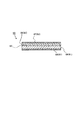
図2に示すように、アルミニウム多孔体端部を圧縮用治具32、32′によって厚み方向に両面から圧縮する。このような押圧方法を採用することで、多孔体の骨格に対する歪量を小さくし、破断していない多孔体骨格数を増やすことができるため多孔体の圧縮部と未圧縮部の境界の強度を強化することができる。
例えば図1に示すように、一方の面からの圧縮を行った場合の厚み方向の変形量をLとした場合に比べると、図2に示す本発明の押圧方法によるアルミニウム多孔体の表面及び裏面におけるそれぞれの変形量はL/2となり、多孔体の骨格の歪み量は1/2となり破断していない骨格数を増やすことができ、多孔体の圧縮部と未圧縮部の境界の強度を強化することが可能となる。
(2)アルミニウム多孔体の端部を端部にRをつけた圧縮用治具によって片面から圧縮する方法
圧縮用冶具にRをつけることで、図3に示すように圧縮部と未圧縮部との境界近傍をなだらかに繋ぐことでき、境界近傍の歪量を小さくすることができる。これにより破断していない多孔体骨格数を増やすことができ、多孔体の圧縮部と未圧縮部の境界の強度を強化することが可能となる。Rの曲率半径は圧縮用治具の角部が丸みを帯びていれば特に制限はないが、曲率半径が0.1mm~5.0mmであることが好ましく、より好ましくは曲率半径が0.2mm~3.0mmである。
(3)アルミニウム多孔体の端部を端部にRをつけた圧縮用治具によって両面から圧縮する方法
この方法は図4に示されるように、上記(1)の方法と(2)の方法を組み合わせたものであり、破断していない多孔体骨格数をより増加させることができ、多孔体の圧縮部と未圧縮部の境界の強度をより強化することが可能となる。
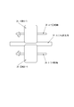
図5において、2枚分の幅を有するアルミニウム多孔体34の中央部を圧縮用治具として端部にRを付けた回転ローラ35によって圧縮して圧縮部33を形成する。圧縮後に圧縮部33の中央部を切断して端部に圧縮部を有する2枚の電極集電体を得る。
図6は端部にRを付けた一組の回転ローラによってアルミニウム多孔体の中央部を両面から圧縮する例を示した図であり、圧縮した部分を面方向の中心線に沿って切断することにより二つのシート状の集電体を得ることができる。
また、複数個組の回転ローラを用いてアルミニウム多孔体の中央部に複数本の帯状の圧縮部を形成し、この帯状の圧縮部のそれぞれを面方向の中心線に沿って切断することにより複数個の集電体を得ることができる。
前記のようにして得た集電体の端部圧縮部にタブリードを接合する。タブリードとしては電極の電気抵抗を低減するために金属箔を用いて、電極の周縁部の少なくとも一方の側の表面に金属箔を接合することが好ましい。また、電気抵抗を低減するために接合方法としては溶接を用いることが好ましい。金属箔を溶接する幅は、あまり太いと電池内に無駄なスペースが増えて電池の容量密度が低下するため、10mm以下が好ましい。あまり細いと溶接が困難になると共に集電効果も下がるため、1mm以上が好ましい。
溶接方法は抵抗溶接や超音波溶接などの方法が使用できるが、超音波溶接の方が、接着面積が広いため好ましい。
得られた集電体の概略図を図7(a)及び図7(b)に示す。アルミニウム多孔体34の圧縮部33にはタブリード37が溶接される。図7(b)は図4(a)のA-A断面図である。
金属箔の材質としては、電気抵抗や電解液に対する耐性を考慮するとアルミニウムが好ましい。また、不純物があると電池及びキャパシタ内で溶出・反応したりするため、純度99.99%以上のアルミニウム箔を用いることが好ましい。また、溶接部分の厚さが電極自体の厚さより薄いことが好ましい。
アルミ箔の厚さは20~500μmとすることが好ましい。
また、金属箔の溶接は集電体に活物質を充填する前・後どちらで行なってもかまわないが、充填前に行なう方が活物質の脱落を抑えられる。特に超音波溶接の場合は充填前に溶接する方が好ましい。また、溶接した部分に活性炭ペーストがついてもよいが、工程途中で剥離する可能性もあるため、充填できないようにマスキングしておくことが好ましい。
活性炭ペーストを調厚された集電体に充填する。集電体の片側からペーストを吹き付けたり、ペーストに集電体を浸漬したり、あるいは印刷機やロールコータを用いることでも充填できる。次に、乾燥機で溶媒を除去する。乾燥温度は80℃以上が好ましいが、温度が高すぎると集電体の酸化や増粘剤、バインダの分解が起きる可能性があるため、250℃以下が好ましい。
乾燥後に、プレス機により厚さ方向に圧縮して電極を得る。プレス機としては平板プレスやローラプレスを用いることができる。平板プレスは集電体の伸びを抑制するためには好ましいが量産に不向きなため、連続処理可能なローラプレスを用いることもできる。ローラプレスを用いる場合は表面にエンボス加工をするなど、伸びを抑制する工夫をしてもよい。
次にアルミニウム多孔体を用いた電池用電極材料及び電池について説明する。例えばリチウム電池の正極に使用する場合は、活物質としてコバルト酸リチウム(LiCoO2)、マンガン酸リチウム(LiMn2O4)、ニッケル酸リチウム(LiNiO2)等を使用する。活物質は導電助剤及びバインダと組み合わせて使用する。従来のリチウム電池用正極材料は、アルミニウム箔の表面に活物質を塗布している。単位面積当たりの電池容量を向上するために、活物質の塗布厚みを厚くしている。また活物質を有効に利用するためにはアルミニウム箔と活物質とが電気的に接触している必要があるので活物質は導電助剤と混合して用いられている。これに対し、本発明のアルミニウム多孔体は気孔率が高く単位面積当たりの表面積が大きい。よって多孔体の表面に薄く活物質を担持させても活物質を有効に利用でき、電池の容量を向上できるとともに、導電助剤の混合量を少なくすることができる。リチウム電池は、上記の正極材料を正極とし、負極には黒鉛、チタン酸リチウム(Li4Ti5O12)、Si等の合金系、あるいはリチウム金属等が使用される。電解質には有機電解液あるいは固体電解質を使用する。このようなリチウム電池は、小さい電極面積でも容量を向上できるため、従来のリチウム電池よりも電池のエネルギー密度を高くすることができる。
リチウム電池に使用される電解質には、非水電解液と固体電解質がある。
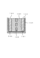
図13は、固体電解質を使用した全固体リチウム電池の縦断面図である。この全固体リチウム電池60は、正極61、負極62、および、両電極間に配置される固体電解質層(SE層)63を備える。正極61は、正極層(正極体)64と正極集電体65とからなり、負極62は、負極層66と負極集電体67とからなる。
電解質として、固体電解質以外に、後述する非水電解液が用いられる。この場合、両極間には、セパレータ(多孔質ポリマーフィルム等)が配置され、非水電解液は両極およびセパレータ中に含浸される。
アルミニウム多孔体をリチウム電池の正極に使用する場合は、活物質としてリチウムを脱挿入できる材料を使用することができ、このような材料をアルミニウム多孔体に充填することでリチウム二次電池に適した電極を得ることができる。正極活物質の材料としては、例えばコバルト酸リチウム(LiCoO2)、ニッケル酸リチウム(LiNiO2)、ニッケルコバルト酸リチウム(LiCo0.3Ni0.7O2)、マンガン酸リチウム(LiMn2O4)、チタン酸リチウム(Li4Ti5O12)、リチウムマンガン酸化合物(LiMyMn2-yO4);M=Cr、Co、Ni)、リチウム酸等を使用する。活物質は導電助剤及びバインダと組み合わせて使用する。従来のリチウムリン酸鉄及びその化合物(LiFePO4、LiFe0.5Mn0.5PO4)であるオリビン化合物などの遷移金属酸化物が挙げられる。また、これらの材料の中に含まれる遷移金属元素を、別の遷移金属元素に一部置換してもよい。
非水電解液としては、極性非プロトン性有機溶媒で使用され、具体的にはエチレンカーボネート、ジエチルカーボネート、ジメチルカーボネート、プロピレンカーボネート、γ-ブチロラクトン及びスルホラン等が使用される。支持塩としては4フッ化ホウ酸リチウム、6フッ化リン酸リチウム、およびイミド塩等が使用されている。
(アルミニウム多孔体に充填する固体電解質)
活物質の他に、さらに、固体電解質を加えて充填してもよい。アルミニウム多孔体に活物質と固体電解質とを充填することで、全固体リチウム電池の電極に適したものとすることができる。ただし、アルミニウム多孔体に充填する材料のうち活物質の割合は、放電容量を確保する観点から、50質量%以上、より好ましくは70質量%以上とすることが好ましい。
活物質(活物質と固体電解質)の充填は、例えば、浸漬充填法や塗工法などの公知の方法を用いることができる。塗工法としては、例えば、ロール塗工法、アプリケータ塗工法、静電塗工法、粉体塗工法、スプレー塗工法、スプレーコータ塗工法、バーコータ塗工法、ロールコータ塗工法、ディップコータ塗工法、ドクターブレード塗工法、ワイヤーバー塗工法、ナイフコータ塗工法、ブレード塗工法、及びスクリーン印刷法などが挙げられる。
図14はキャパシタ用電極材料を用いたキャパシタの一例を示す断面模式図である。セパレータ142で仕切られた有機電解液143中に、アルミニウム多孔体に電極活物質を担持した電極材料を分極性電極141として配置している。分極性電極141はリード線144に接続しており、これら全体がケース145中に収納されている。アルミニウム多孔体を集電体として使用することで、集電体の表面積が大きくなり、活物質としての活性炭を薄く塗布しても高出力、高容量化可能なキャパシタを得ることができる。
活性炭ペーストを充填する。キャパシタの容量を大きくするためには主成分である活性炭の量が多い方が良く、乾燥後(溶媒除去後)の組成比で活性炭が90%以上あることが好ましい。また導電助剤やバインダは必要ではあるが容量低下の要因であり、バインダは更に内部抵抗を増大させる要因となるためできる限り少ない方がよい。導電助剤は10質量%以下、バインダは10質量%以下が好ましい。
上記のようにして得られた電極を適当な大きさに打ち抜いて2枚用意し、セパレータを挟んで対向させる。そして、必要なスペーサを用いてセルケースに収納し、電解液を含浸させる。最後に絶縁ガスケットを介してケースに蓋をして封口することにより非水電解液を用いるキャパシタを作製することができる。非水系の材料を使用する場合は、キャパシタ内の水分を限りなく少なくするため、キャパシタの作製は水分の少ない環境下で行い、封止は減圧環境下で行う。なお、本発明の集電体、電極を用いていればキャパシタとしては特に限定されず、これ以外の方法により作製されるものでも構わない。
また、負極は特に限定されず従来の負極用電極を使用可能であるが、アルミ箔を集電体に用いた従来の電極では容量が小さいため、前述の発泡状ニッケルのような多孔体に活物質を充填した電極が好ましい。
アルミニウム多孔体は、溶融塩電池用の電極材料として使用することもできる。アルミニウム多孔体を正極材料として使用する場合は、活物質として亜クロム酸ナトリウム(NaCrO2)、二硫化チタン(TiS2)等、電解質となる溶融塩のカチオンをインターカレーションすることができる金属化合物を使用する。活物質は導電助剤及びバインダと組み合わせて使用する。導電助剤としてはアセチレンブラック等が使用できる。またバインダとしてはポリテトラフルオロエチレン(PTFE)等を使用できる。活物質としてクロム酸ナトリウムを使用し、導電助剤としてアセチレンブラックを使用する場合には、PTFEはこの両者をより強固に固着することができ好ましい。
例えばカリウムビス(フルオロスルフォニル)アミド<K-N(SO2F)2;KFSA>とナトリウムビス(フルオロスルフォニル)アミド<Na-N(SO2F)2;NaFSA>とを組み合わせて使用すると、電池の動作温度を90℃以下とすることができる。
(導電層の形成)
ウレタン樹脂成形体として、気孔率95%、1インチ当たりの気孔数(セル数)約50個、気孔径約550μm、厚さ1mmのウレタン発泡体を準備し、これを100mm×30mm角に切断した。このポリウレタンフォームの表面にスパッタリングによりアルミニウムを目付量10g/m2で成膜して導電層を形成した。
表面に導電層を形成したウレタン発泡体をワークとして、給電機能を有する治具にセットした後、アルゴン雰囲気かつ低水分(露点-30℃以下)としたグローブボックス内に入れ、温度40℃の溶融塩アルミめっき浴(33mol%EMIC-67mol%AlCl3)に浸漬した。ワークをセットした治具を整流器の陰極側に接続し、対極のアルミニウム板(純度99.99%)を陽極側に接続した。電流密度3.6A/dm2の直流電流を90分間印加してめっきすることにより、ウレタン発泡体表面に150g/m2の重量のアルミニウムめっき層が形成されたアルミニウム構造体を得た。攪拌はテフロン(登録商標)製の回転子を用いてスターラにて行った。ここで、電流密度はウレタン発泡体の見かけの面積で計算した値である。
前記アルミニウム構造体を温度500℃のLiCl-KCl共晶溶融塩に浸漬し、-1Vの負電位を30分間印加した。溶融塩中にポリウレタンの分解反応による気泡が発生した。その後大気中で室温まで冷却した後、水洗して溶融塩を除去し、樹脂が除去されたアルミニウム多孔体を得た。得られたアルミニウム多孔体は連通気孔を有し、気孔率が芯材としたウレタン発泡体と同様に高いものであった。
得られたアルミニウム多孔体をローラプレスにより厚さ1.0mmに調厚し、1.5cm角に切断した。
溶接の準備として、圧縮用治具として幅5mmのSUSブロック(棒)とハンマーを用いて、アルミニウム多孔体の1辺の端から5mm部分を両側からSUSブロックで挟み、SUSブロックをハンマーで叩いて圧縮して厚み100μmの圧縮部を形成した。
その後、以下の条件でタブリードをスポット溶接によって溶接した。
<溶接条件>
溶接装置: パナソニック社製 Hi-Max100、型番YG-101UD
(最大250Vまで印加可能)
容量100Ws、0.6kVA
電極 : 2mmφの銅電極
荷重 : 8kgf
電圧 : 140V
<タブリード>
材質 : アルミニウム
寸法 : 幅5mm、長さ7cm、厚み100μm
表面状態: ベーマイト加工
得られたアルミニウム多孔体を観察すると図1に示すように端部はアルミニウム多孔体の両面から圧縮された状態であった。
図6に得られたアルミニウム多孔体の概略図を図6(a)に示す。アルミニウム多孔体34の圧縮部33にはタブリード37が溶接される。図6(b)は図6(a)のA-A断面図である。
また、圧縮部と未圧縮部との境界線部分における骨格の破断数をカウントすると1.4個/mmであった。
実施例1において、SUSブロックの端部に曲率半径0.5mmのRを付けたSUSブロックを用い、アルミニウム多孔体を基台上に載置しアルミニウム多孔体の1辺の端から5mm部分に前記SUSブロックを介してハンマーで叩いた以外は実施例1と同様にして端部圧縮部にタブリードをスポット溶接したアルミニウム多孔体を得た。圧縮部と未圧縮部との境界線部分における骨格の破断数をカウントすると1.5個/mmであった。
実施例1において、SUSブロックの端部に曲率半径0.5mmのRを付けたSUSブロックを用いたこと以外は、アルミニウム多孔体を基台上に載置しアルミニウム多孔体の1辺の端から5mm部分に前記SUSブロックを介してハンマーで叩いた以外は実施例1と同様にして端部圧縮部にタブリードをスポット溶接したアルミニウム多孔体を得た。圧縮部と未圧縮部との境界線部分における骨格の破断数をカウントすると1.0個/mmであった。
実施例2において、SUSブロックの端部にRを付けないSUSブロックを用いたこと以外は、アルミニウム多孔体を基台上に載置しアルミニウム多孔体の1辺の端から5mm部分に前記SUSブロックを介してハンマーで叩いた以外は実施例1と同様にして端部圧縮部にタブリードをスポット溶接したアルミニウム多孔体を得た。圧縮部と未圧縮部との境界線部分における骨格の破断数をカウントすると3.8個/mmであった。
2 導電層
3 アルミニウムめっき層
11 帯状樹脂
12 サプライボビン
13 デフレクタロール
14 導電性塗料の懸濁液
15 槽
16 熱風ノズル
17 絞りロール
18 巻取りボビン
21a,21b めっき槽
22 帯状樹脂
23,28 めっき浴
24 円筒状電極
25,27 陽極
26 電極ローラ
32、32′ 圧縮用治具
33 圧縮部
34 アルミニウム多孔体
35 回転ローラ
36 ローラ回転軸
37 タブリード
38 絶縁・封止用テープ
60 リチウム電池
61 正極
62 負極
63 固体電解質層(SE層)
64 正極層(正極体)
65 正極集電体
66 負極層
67 負極集電体
121 正極
122 負極
123 セパレータ
124 押さえ板
125 バネ
126 押圧部材
127 ケース
128 正極端子
129 負極端子
130 リード線
141 分極性電極
142 セパレータ
143 有機電解液
144 リード線
145 ケース
Claims (10)
- 端部にタブリードを接続するための厚み方向に圧縮された圧縮部を有する集電体用三次元網状アルミニウム多孔体であって、前記圧縮部分がアルミニウム多孔体の厚み方向の中央部に形成されていることを特徴とする集電体用三次元網状アルミニウム多孔体。
- 前記圧縮部分における圧縮部と未圧縮部との境界部分の表面の断面が曲線状であることを特徴とする請求項1に記載の集電体用三次元網状アルミニウム多孔体。
- 端部にタブリードを接続するための厚み方向に圧縮された圧縮部を有する集電体用三次元網状アルミニウム多孔体であって、前記圧縮部分がアルミニウム多孔体の厚み方向の一方の側にあり、前記圧縮部における圧縮部と未圧縮部の境界部分の表面の断面が曲線状であることを特徴とする集電体用三次元網状アルミニウム多孔体。
- 三次元網状アルミニウム多孔体の端部を厚み方向に圧縮してタブリードを接続するための圧縮部を形成することにより集電体用三次元網状アルミニウム多孔体を製造する方法であって、該アルミニウム多孔体の端部の表裏両面を圧縮用治具で押圧することによりアルミニウム多孔体の厚み方向の中央部に圧縮部を形成することを特徴とする集電体用三次元網状アルミニウム多孔体の製造方法。
- 三次元網状アルミニウム多孔体の端部を厚み方向に圧縮してタブリードを接続するための圧縮部を形成することにより集電体用三次元網状アルミニウム多孔体を製造する方法であって、該アルミニウム多孔体の中央部の表裏両面を圧縮用治具で押圧することによりアルミニウム多孔体の厚み方向の中央部に一本の帯状の圧縮部を形成し、次いで前記帯状の圧縮部を面方向の中心線に沿って切断することを特徴とする集電体用三次元網状アルミニウム多孔体の製造方法。
- 三次元網状アルミニウム多孔体の端部を厚み方向に圧縮してタブリードを接続するための圧縮部を形成することにより集電体用三次元網状アルミニウム多孔体を製造する方法であって、該アルミニウム多孔体の中央部において間隔をあけて表裏両面の複数箇所を圧縮用治具で押圧することによりアルミニウム多孔体の厚み方向の中央部に複数本の帯状の圧縮部を形成し、次いで前記帯状の圧縮部を面方向の中心線に沿って切断することを特徴とする集電体用三次元網状アルミニウム多孔体の製造方法。
- 前記圧縮用治具の、三次元網状アルミニウム多孔体の圧縮部と未圧縮部の境界部分を押圧によって形成する角部の表面の断面形状が曲線状であることを特徴とする請求項4~6のいずれか一項に記載の集電体用三次元網状アルミニウム多孔体の製造方法。
- 三次元網状アルミニウム多孔体の端部を厚み方向に圧縮してタブリードを接続するための圧縮部を形成して集電体用三次元網状アルミニウム多孔体を製造する方法であって、前記圧縮用治具は三次元網状アルミニウム多孔体の圧縮部と未圧縮部の境界部分を形成する角部の表面の断面形状が曲線状であり、この圧縮用治具によってアルミニウム多孔体の端部の一方の側の面を圧縮用治具で押圧することによりアルミニウム多孔体の厚み方向の他方の側に圧縮部を形成することを特徴とする集電体用三次元網状アルミニウム多孔体の製造方法。
- 三次元網状アルミニウム多孔体の端部を厚み方向に圧縮してタブリードを接続するための圧縮部を形成して集電体用三次元網状アルミニウム多孔体を製造する方法であって、前記圧縮用治具は三次元網状アルミニウム多孔体の圧縮部と未圧縮部の境界部分を形成する角部の表面の断面形状が曲線状であり、この圧縮用治具によってアルミニウム多孔体の中央部の一方の側の面を圧縮用治具で押圧することによりアルミニウム多孔体の厚み方向の他方の側に一本の帯状の圧縮部を形成し、次いで前記帯状の圧縮部を面方向の中心線に沿って切断することを特徴とする集電体用三次元網状アルミニウム多孔体の製造方法。
- 三次元網状アルミニウム多孔体の端部を厚み方向に圧縮してタブリードを接続するための圧縮部を形成することにより集電体用三次元網状アルミニウム多孔体を製造する方法であって、前記圧縮用治具は三次元網状アルミニウム多孔体の圧縮部と未圧縮部の境界部分を形成する角部の表面の断面形状が曲線状であり、該アルミニウム多孔体の中央部において間隔をあけて表裏両面の複数箇所を前記圧縮用治具で押圧することによりアルミニウム多孔体の厚み方向の中央部に複数本の帯状の圧縮部を形成し、次いで前記帯状の圧縮部を面方向の中心線に沿って切断することを特徴とする集電体用三次元網状アルミニウム多孔体の製造方法。
Priority Applications (4)
| Application Number | Priority Date | Filing Date | Title |
|---|---|---|---|
| DE201211000876 DE112012000876T5 (de) | 2011-02-18 | 2012-02-15 | Poröser Aluminiumkörper mit dreidimensionalem Netzwerk für Stromkollektor und Verfahren zu dessen Erzeugung |
| KR1020137021840A KR20140012065A (ko) | 2011-02-18 | 2012-02-15 | 집전체용 3차원 그물 형상 알루미늄 다공체 및 그의 제조 방법 |
| CN201280008499XA CN103348427A (zh) | 2011-02-18 | 2012-02-15 | 集电体用三维网状铝多孔体及其制备方法 |
| US13/494,353 US20120308886A1 (en) | 2011-02-18 | 2012-06-12 | Three-dimensional network aluminum porous body for current collector and method for producing the same |
Applications Claiming Priority (4)
| Application Number | Priority Date | Filing Date | Title |
|---|---|---|---|
| JP2011032789 | 2011-02-18 | ||
| JP2011-032789 | 2011-02-18 | ||
| JP2011111049A JP2012186134A (ja) | 2011-02-18 | 2011-05-18 | 集電体用三次元網状アルミニウム多孔体及びその製造方法 |
| JP2011-111049 | 2011-05-18 |
Related Child Applications (1)
| Application Number | Title | Priority Date | Filing Date |
|---|---|---|---|
| US13/494,353 Continuation US20120308886A1 (en) | 2011-02-18 | 2012-06-12 | Three-dimensional network aluminum porous body for current collector and method for producing the same |
Publications (1)
| Publication Number | Publication Date |
|---|---|
| WO2012111702A1 true WO2012111702A1 (ja) | 2012-08-23 |
Family
ID=46672615
Family Applications (1)
| Application Number | Title | Priority Date | Filing Date |
|---|---|---|---|
| PCT/JP2012/053518 Ceased WO2012111702A1 (ja) | 2011-02-18 | 2012-02-15 | 集電体用三次元網状アルミニウム多孔体及びその製造方法 |
Country Status (6)
| Country | Link |
|---|---|
| US (1) | US20120308886A1 (ja) |
| JP (1) | JP2012186134A (ja) |
| KR (1) | KR20140012065A (ja) |
| CN (1) | CN103348427A (ja) |
| DE (1) | DE112012000876T5 (ja) |
| WO (1) | WO2012111702A1 (ja) |
Cited By (1)
| Publication number | Priority date | Publication date | Assignee | Title |
|---|---|---|---|---|
| WO2016152824A1 (ja) * | 2015-03-26 | 2016-09-29 | 住友電気工業株式会社 | ヒートシンク及び電子機器 |
Families Citing this family (12)
| Publication number | Priority date | Publication date | Assignee | Title |
|---|---|---|---|---|
| JP6024373B2 (ja) * | 2012-10-12 | 2016-11-16 | 住友電気工業株式会社 | 燃料電池およびその操業方法 |
| JP2016110678A (ja) * | 2014-12-09 | 2016-06-20 | 株式会社東芝 | ディップコート用保持治具、及びこれを用いたディップコートシステム |
| JP2017168634A (ja) * | 2016-03-16 | 2017-09-21 | 太陽誘電株式会社 | 電気化学デバイス用電極、電気化学デバイス、電気化学デバイス用電極の製造方法及び電気化学デバイスの製造方法 |
| KR102289692B1 (ko) * | 2016-09-06 | 2021-08-13 | 삼성에스디아이 주식회사 | 두께의 차이를 갖는 전극탭의 제조방법 및 이를 포함하는 이차전지 |
| DE102016217383A1 (de) | 2016-09-13 | 2018-03-15 | Robert Bosch Gmbh | Verfahren zur Herstellung von Elektroden mit verbesserter Stromsammlerstruktur |
| KR102298059B1 (ko) * | 2017-04-06 | 2021-09-02 | 주식회사 엘지에너지솔루션 | 리튬 이차전지의 제조방법 |
| KR102436414B1 (ko) * | 2017-10-11 | 2022-08-24 | 주식회사 엘지에너지솔루션 | 리튬 금속으로 이루어진 음극 및 탭으로 구성된 음극 구조체 |
| JP7376409B2 (ja) * | 2020-03-27 | 2023-11-08 | 古河電池株式会社 | リチウムイオン電池、およびリチウムイオン電池の製造方法 |
| EP4220780B1 (en) * | 2021-11-30 | 2025-12-17 | Contemporary Amperex Technology (Hong Kong) Limited | Current collector and preparation method therefor, secondary battery, battery module, battery pack, and electrical device |
| CN114520336B (zh) * | 2022-04-21 | 2022-08-02 | 宁德时代新能源科技股份有限公司 | 集流体及其制造方法和设备、及集流体预制件 |
| WO2024219071A1 (ja) * | 2023-04-18 | 2024-10-24 | 株式会社Gsユアサ | 集電箔、蓄電装置、及び、集電箔の製造方法 |
| CN117046979B (zh) * | 2023-06-29 | 2025-08-15 | 中国科学院海洋研究所 | 具有微纳结构的金属箔、聚合物薄膜的制备方法及其应用 |
Citations (5)
| Publication number | Priority date | Publication date | Assignee | Title |
|---|---|---|---|---|
| JPH09199137A (ja) * | 1996-01-24 | 1997-07-31 | Shin Kobe Electric Mach Co Ltd | 蓄電池用極板 |
| JPH09199117A (ja) * | 1996-01-12 | 1997-07-31 | Furukawa Battery Co Ltd:The | 正極板およびその製造方法 |
| JP2000323137A (ja) * | 1999-05-14 | 2000-11-24 | Matsushita Electric Ind Co Ltd | 電池用電極の製造方法 |
| JP2002289166A (ja) * | 2001-03-27 | 2002-10-04 | Sanyo Electric Co Ltd | 電池の製造方法 |
| JP2010272425A (ja) * | 2009-05-22 | 2010-12-02 | Mitsubishi Materials Corp | 非水電解質二次電池用電極およびその製造方法 |
Family Cites Families (8)
| Publication number | Priority date | Publication date | Assignee | Title |
|---|---|---|---|---|
| JPS5686459A (en) | 1979-12-14 | 1981-07-14 | Matsushita Electric Ind Co Ltd | Spiral-shaped electrode and manufacture thereof |
| JP2764958B2 (ja) * | 1988-11-11 | 1998-06-11 | 松下電器産業株式会社 | 円筒形二次電池 |
| US5087245A (en) | 1989-03-13 | 1992-02-11 | Ivac Corporation | System and method for detecting abnormalities in intravascular infusion |
| JP3413662B2 (ja) * | 1992-01-13 | 2003-06-03 | 上村工業株式会社 | アルミニウム多孔体の製造方法 |
| JP3568052B2 (ja) * | 1994-12-15 | 2004-09-22 | 住友電気工業株式会社 | 金属多孔体、その製造方法及びそれを用いた電池用極板 |
| JPH09245777A (ja) * | 1996-03-12 | 1997-09-19 | Furukawa Battery Co Ltd:The | 二次電池用電極とその製造方法 |
| JP4023990B2 (ja) * | 2000-08-30 | 2007-12-19 | 松下電器産業株式会社 | 電池用電極板の製造方法および製造装置 |
| JP5094013B2 (ja) * | 2004-12-10 | 2012-12-12 | キヤノン株式会社 | リチウム二次電池用の電極構造体及び該電極構造体を有する二次電池 |
-
2011
- 2011-05-18 JP JP2011111049A patent/JP2012186134A/ja active Pending
-
2012
- 2012-02-15 DE DE201211000876 patent/DE112012000876T5/de not_active Withdrawn
- 2012-02-15 WO PCT/JP2012/053518 patent/WO2012111702A1/ja not_active Ceased
- 2012-02-15 CN CN201280008499XA patent/CN103348427A/zh active Pending
- 2012-02-15 KR KR1020137021840A patent/KR20140012065A/ko not_active Withdrawn
- 2012-06-12 US US13/494,353 patent/US20120308886A1/en not_active Abandoned
Patent Citations (5)
| Publication number | Priority date | Publication date | Assignee | Title |
|---|---|---|---|---|
| JPH09199117A (ja) * | 1996-01-12 | 1997-07-31 | Furukawa Battery Co Ltd:The | 正極板およびその製造方法 |
| JPH09199137A (ja) * | 1996-01-24 | 1997-07-31 | Shin Kobe Electric Mach Co Ltd | 蓄電池用極板 |
| JP2000323137A (ja) * | 1999-05-14 | 2000-11-24 | Matsushita Electric Ind Co Ltd | 電池用電極の製造方法 |
| JP2002289166A (ja) * | 2001-03-27 | 2002-10-04 | Sanyo Electric Co Ltd | 電池の製造方法 |
| JP2010272425A (ja) * | 2009-05-22 | 2010-12-02 | Mitsubishi Materials Corp | 非水電解質二次電池用電極およびその製造方法 |
Cited By (2)
| Publication number | Priority date | Publication date | Assignee | Title |
|---|---|---|---|---|
| WO2016152824A1 (ja) * | 2015-03-26 | 2016-09-29 | 住友電気工業株式会社 | ヒートシンク及び電子機器 |
| JP2016184648A (ja) * | 2015-03-26 | 2016-10-20 | 住友電気工業株式会社 | ヒートシンク及び電子機器 |
Also Published As
| Publication number | Publication date |
|---|---|
| KR20140012065A (ko) | 2014-01-29 |
| CN103348427A (zh) | 2013-10-09 |
| US20120308886A1 (en) | 2012-12-06 |
| DE112012000876T5 (de) | 2013-12-24 |
| JP2012186134A (ja) | 2012-09-27 |
Similar Documents
| Publication | Publication Date | Title |
|---|---|---|
| US8465875B2 (en) | Three-dimensional network aluminum porous body for current collector, electrode using the aluminum porous body, and battery, capacitor and lithium-ion capacitor each using the electrode | |
| US8497037B2 (en) | Current collector using three-dimensional network aluminum porous body, electrode using the current collector, and nonaqueous electrolyte battery, capacitor and lithium-ion capacitor with nonaqueous electrolytic solution, each using the electrode, and method for producing the electrode | |
| WO2012111702A1 (ja) | 集電体用三次元網状アルミニウム多孔体及びその製造方法 | |
| US20130004856A1 (en) | Three-dimensional network aluminum porous body for current collector, current collector using the aluminum porous body, electrode using the current collector, and nonaqueous electrolyte battery, capacitor and lithium-ion capacitor, each using the electrode | |
| JP5961117B2 (ja) | 三次元網状アルミニウム多孔体及び該アルミニウム多孔体を用いた電極並びに該電極を用いた非水電解質電池、非水電解液を用いたキャパシタ及びリチウムイオンキャパシタ | |
| JP5976551B2 (ja) | 三次元網状アルミニウム多孔体及び該アルミニウム多孔体を用いた電極並びに該電極を用いた非水電解質電池、非水電解液を用いたキャパシタ及びリチウムイオンキャパシタ | |
| JP5883288B2 (ja) | 集電体用三次元網状アルミニウム多孔体、該アルミニウム多孔体を用いた集電体、電極、非水電解質電池、キャパシタ及びリチウムイオンキャパシタ | |
| WO2012111601A1 (ja) | 三次元網状アルミニウム多孔体、該アルミニウム多孔体を用いた電極、該電極を用いた非水電解質電池、非水電解液を用いたキャパシタ及びリチウムイオンキャパシタ | |
| WO2012111585A1 (ja) | アルミニウム多孔体及びその製造方法 | |
| WO2012111613A1 (ja) | 電気化学デバイス用電極およびその製造方法 | |
| US20120315540A1 (en) | Three-dimensional network aluminum porous body for current collector, electrode using the aluminum porous body, and nonaqueous electrolyte battery, nonaqueous electrolytic solution capacitor and lithium-ion capacitor each using the electrode | |
| WO2012111659A1 (ja) | 集電体用三次元網状アルミニウム多孔体、該アルミニウム多孔体を用いた電極、非水電解質電池、キャパシタ及びリチウムイオンキャパシタ | |
| JP5973921B2 (ja) | 三次元網状アルミニウム多孔体、該アルミニウム多孔体を用いた集電体及び電極並びに該電極を用いた非水電解質電池、非水電解液を用いたキャパシタ及びリチウムイオンキャパシタ | |
| JPWO2012111699A1 (ja) | 三次元網状アルミニウム多孔体を用いた電極、該電極を用いた非水電解質電池、非水電解液を用いたキャパシタ及びリチウムイオンキャパシタ | |
| JP5876839B2 (ja) | 集電体用三次元網状アルミニウム多孔体、該アルミニウム多孔体を用いた集電体、電極、非水電解質電池、キャパシタ及びリチウムイオンキャパシタ | |
| JP2012251231A (ja) | アルミニウム多孔体の製造方法 |
Legal Events
| Date | Code | Title | Description |
|---|---|---|---|
| 121 | Ep: the epo has been informed by wipo that ep was designated in this application |
Ref document number: 12747202 Country of ref document: EP Kind code of ref document: A1 |
|
| WWE | Wipo information: entry into national phase |
Ref document number: 1120120008766 Country of ref document: DE Ref document number: 112012000876 Country of ref document: DE |
|
| ENP | Entry into the national phase |
Ref document number: 20137021840 Country of ref document: KR Kind code of ref document: A |
|
| 122 | Ep: pct application non-entry in european phase |
Ref document number: 12747202 Country of ref document: EP Kind code of ref document: A1 |