WO2012111372A1 - イオン発生素子 - Google Patents
イオン発生素子 Download PDFInfo
- Publication number
- WO2012111372A1 WO2012111372A1 PCT/JP2012/050907 JP2012050907W WO2012111372A1 WO 2012111372 A1 WO2012111372 A1 WO 2012111372A1 JP 2012050907 W JP2012050907 W JP 2012050907W WO 2012111372 A1 WO2012111372 A1 WO 2012111372A1
- Authority
- WO
- WIPO (PCT)
- Prior art keywords
- ion generating
- ion
- reflector
- generating element
- electrode
- Prior art date
- Legal status (The legal status is an assumption and is not a legal conclusion. Google has not performed a legal analysis and makes no representation as to the accuracy of the status listed.)
- Ceased
Links
Images












Classifications
-
- H—ELECTRICITY
- H01—ELECTRIC ELEMENTS
- H01T—SPARK GAPS; OVERVOLTAGE ARRESTERS USING SPARK GAPS; SPARKING PLUGS; CORONA DEVICES; GENERATING IONS TO BE INTRODUCED INTO NON-ENCLOSED GASES
- H01T23/00—Apparatus for generating ions to be introduced into non-enclosed gases, e.g. into the atmosphere
Definitions
- the present invention relates to an electrode shape of an ion generating element that generates ions by discharging in the air.
- Patent Document 3 discloses an ion generating element that repels ions generated by the ion generating electrode 1 and discharges them into the space by placing the ion behind the ion generating electrode 1.
- Patent Document 4 describes the structure of an ion generating element that is released into the substrate.
- the ion generating element is considered in consideration of safety to the human body.
- the ion generating element is used by being installed in a casing having an opening for ion emission.
- the ion emission opening has a diameter of 10 mm or less so that a human cannot directly touch it.
- an object of the present invention is to provide an ion generating element capable of discharging ions generated by an ion generating electrode to an air path from an opening of a casing with a simple mechanism and efficiently.
- An ion generating element has a needle-shaped tip, and an ion generating electrode that generates ions at the tip when a high voltage is applied to the ion generating element in a direction opposite to the ion emission direction.
- a reflector made of a dish-like conductive material is provided at a position facing the tip of the ion generating electrode, and a potential having the same polarity is applied to the ion generating electrode and the reflector.
- the tip of the ion generating electrode is formed so as to be the center of the reflector figure in plan view.
- the dish-shaped reflector is a rotating body having the ion generating electrode as a rotation axis and has a circular section (a radius is constant).
- the dish-shaped reflector is a rotating body having the ion generating electrode as a rotation axis, and the cross section is a parabola.
- the dish-shaped reflector is an inverted polygonal pyramid centered on the ion generating electrode, that is, the cross section is trapezoidal.
- the dish-shaped reflector is a rotating body having the ion generating electrode as a rotation axis, and the cross section is a flat plate with a raised peripheral portion.
- the depth of the dish-shaped reflector is shallower than the height of the needle-shaped ion generating electrode.
- the dish-shaped reflector may be separated from the needle-shaped ion generating electrode in terms of mechanical structure and only electrically connected.
- the ion generating electrode is installed in a casing having an opening for ion emission, the direction toward the air passage, that is, the direction perpendicular to the opening in comparison with the flat reflector Therefore, it is possible to provide an ion generating element capable of efficiently discharging ions to the air passage from the opening for discharging ions in the casing.
- the distance between the tip of the ion generation electrode and the reflector becomes the same length in both the front and rear directions and the left and right directions. Ions generated at the tip receive a repulsive force equally from both the tip of the electrode and the reflector. Thereby, the ion generating element with the directivity of the direction which goes to an air path can be provided.
- the distance between the discharge electrode tip and the reflector can be compared vertically. Then, the front and rear and the left and right directions become close, and the ions generated at the tip of the ion generating electrode receive a strong repulsive force from the reflector to converge the ions. As a result, it is possible to provide an ion generating element having a very directivity in the direction toward the air path.
- the reflector an inverted polygonal pyramid with the ion generating electrode as the central axis, ions generated at the tip of the ion generating electrode are strongly emitted from the reflector, as in the case of forming the reflector as a part of a sphere. The ions are converged by the repulsive force. As a result, an ion generating element having a sharp directivity in the direction toward the air passage can be provided.
- the reflector a flat plate with the ion generating electrode as the central axis and the peripheral edge being raised, the shape of the reflector is simplified and the shape freedom of the reflector is increased, while ions generated at the tip of the ion generating electrode form an electric field.
- An ion generating element having a sharp directivity in the direction toward the air path can be provided by receiving a strong repulsive force from the raised peripheral part of the reflector that acts greatly on the surface and converging ions.
- the depth of the reflector is shallower than the height of the needle-like ion generating electrode, and the tip of the ion generating electrode protrudes from the upper end of the reflector, so that the ion generation from the tip of the ion generating electrode can be prevented. Therefore, it is possible to provide an ion generating element with a sharp directivity that eliminates the adverse effect of suppression.
- the ion generating electrode is formed without being mechanically connected to the reflector, it is possible to add only the reflector using the conventional ion generating electrode. Can be lowered.
- the ion generating element based on the present invention in order to prevent the high voltage portion from being touched, even when the ion generating electrode is installed in a casing having an ion discharge opening, Since the directivity of the electric field in the direction toward the path, that is, in the direction perpendicular to the opening, is sharp, it is possible to provide an ion generating element that can efficiently emit ions into the air path.
- FIGS. 4A to 4C are diagrams showing an electrode structure of the ion generating element according to the first embodiment of the present invention.
- the ion generating element shown in FIGS. 4A to 4C is composed of a needle-like ion generating electrode 1 and a dish-like reflector 4 formed of a conductive material. 4 is electrically connected.
- the dish-like reflector 4 is a part of a sphere formed as a rotating body having the ion generating electrode 1 as a rotation axis, and the cross-sectional shape thereof is an arc (constant radius).
- the needle-like ion generating electrode 1 is disposed so as to protrude from the dish-like reflector 4 with the diameter of the sphere as an axis. Further, when viewed from above the needle-like ion generating electrode 1, it is installed at the center of a circle formed by the dish-like reflector 4. Further, the length from the contact point between the reflector 4 and the ion generation electrode 1 to the tip of the ion generation electrode 1 at this time is defined as the height of the ion generation electrode 1.
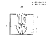
- FIG. 5 is a conceptual diagram showing the emission state of ions 5 when the ion generating element according to the first embodiment of the present invention is installed in the casing 3 having an ion emission opening.
- the distance from the front and rear and the left and right directions are the same length, and the ions 5 generated at the tip of the ion generating electrode 1 receive the repulsive force equally from both the electrode 1 and the reflector 4.
- the distance between the front end of the discharge electrode and the reflection plate increases as the front-rear direction and the left-right direction increase with respect to the discharge electrode, so that the repulsive force inversely proportional to the square of the distance varies greatly.
- the repulsive force is received with the same magnitude from any direction in the front / rear and left / right directions. Sex is sharp.
- the ion generating element is installed in the casing 3 having the ion emission opening, the directivity of the electric field in the direction toward the air passage, that is, the direction perpendicular to the opening is sharp. Therefore, it is possible to provide an ion generating element that can efficiently emit ions 5 into the air passage.
- the above-described ion generating element according to the present invention is mounted on an electric device such as an air conditioner, a dehumidifier, a humidifier, an air purifier, a refrigerator, a fan heater, a microwave oven, a washer / dryer, a vacuum cleaner, or a sterilizer. Is possible.
- Such an electrical device can be provided with a plurality of ion generating elements according to the present invention, and each can generate positive ions and negative ions. Moreover, it is good to mount the sending means (for example, ventilation fan) which sends out both the positive ion and negative ion which passed the opening part of the casing in the air.
- the sending means for example, ventilation fan
- FIG. 6 is a side sectional view showing an electrode structure of an ion generating element according to a second embodiment of the present invention and an ion emission state when the ion generating element is installed in a casing having an ion emission opening. It is.
- the basic structure is the same as that of the first embodiment.
- the reflector 4 instead of the reflector that forms part of the sphere of the first embodiment, the reflector 4 that forms part of a paraboloid or long sphere, and did.
- the vertical direction (axial direction of the needle electrode) of the reflector 4 is closer to the discharge electrode 1 in addition to the front-rear direction and the left-right direction of the reflector 4, and exhibits a stronger repulsive force. For this reason, it is possible to form a converged electric field as compared with the first embodiment, and ions 5 can be emitted with a stronger orientation.
- the ion generating element is installed in the casing 3 having the ion emission opening, the directivity of the electric field in the direction toward the air passage, that is, the direction perpendicular to the opening is sharp. Therefore, it is possible to provide an ion generating element that can efficiently emit ions 5 into the air passage.
- the ion generating electrode of the ion generating element according to the first embodiment is 5 mm
- the diameter of the dish-shaped reflector is 14 mm
- the depth is 4 mm
- the ion generating electrode is 1 mm above the tip of the ion generating electrode.
- the length of the ion generating electrode of the ion generating element according to the second embodiment is 5 mm
- the width of the dish-shaped reflector is 14 mm
- the depth is 4 mm, 1 mm from the tip of the ion generating electrode.
- the result is that the electric field strength is the highest in the case where the depth is 4 mm in any place at a distance of 0.5 mm or more from the needle tip.
- peripheral portion of the reflector forms an edge and electric field concentration occurs, and that the peripheral portion approaches the tip of the ion generating electrode.
- the directivity of ion emission is directed by the repulsive force exerted at the tip of the ion generating electrode and the peripheral edge of the reflector.
- the shape of the intermediate portion from the foot portion of the ion generating electrode (the portion in contact with the reflector) to the peripheral portion of the reflector does not necessarily have a curvature, and can be omitted. It can be seen that does not need to be formed integrally with the ion generating electrode and only requires electrical connection.
- FIG. 9A is a top view showing the electrode structure of the ion generating element according to the third embodiment of the present invention
- FIG. 9B is a side sectional view showing the electrode structure of the ion generating element according to the third embodiment of the present invention
- FIG. It is a perspective view which shows the electrode structure of the ion generating element which concerns on 3rd Embodiment of this invention.
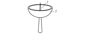
- the present embodiment has basically the same structure as that of the first embodiment, the reflector 7 is provided not in the foot of the discharge electrode 1 but in the middle. Since the reflector 7 is positioned in the air, the degree of freedom for attachment to a substrate or the like is increased as compared with the first embodiment. The effect is similar.
- FIG. 10A is a top view showing the electrode structure of the ion generating element according to the fourth embodiment of the present invention
- FIG. 10B is a side sectional view showing the electrode structure of the ion generating element according to the fourth embodiment of the present invention
- FIG. It is a perspective view which shows the electrode structure of the ion generating element which concerns on 4th Embodiment of this invention.
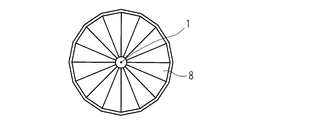
- the reflector need only be uniform in the front-rear and left-right directions with the ion generating electrode as the center, the reflector need not be a rotating body with the ion generating electrode as a rotation axis, and if it is close to the rotating body Good. That is, it is determined that the same effect can be obtained if the rotating body 8 is an inverted polygonal pyramid that is a continuous body of a plurality of triangles centered on the ion generating electrode 1. Examples of this are shown in FIGS. 10A to 10C. In FIGS. 10A to 10C, a hexagon is used. However, it is considered that the same effect can be obtained if there is a polygon if there is a slight difference.
- FIG. 11A is a top view showing an electrode structure of an ion generating element according to a fifth embodiment of the present invention
- FIG. 11B is a side sectional view showing an electrode structure of an ion generating element according to the fifth embodiment of the present invention
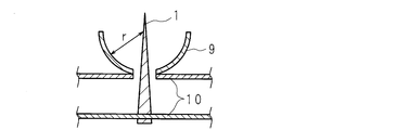
- FIG. It is a perspective view which shows the electrode structure of the ion generating element which concerns on 5th Embodiment of this invention. This is an example in which an opening is provided at the lowermost part of the reflector 9 and the ion generating electrode 1 is installed in a state of passing through the opening, and it is considered that the same effect can be obtained.
- the influence of the middle part from the central part of the reflector to the peripheral part is considered to be small and can be omitted, and in order to ensure only the relative distance between the needle tip and the peripheral part of the reflector,
- the reflector 9 was placed on a substrate 10 different from the substrate 10 on which the ion generating electrode 1 is fixed. The same effect as that of the third embodiment can be expected.
- FIG. 12A is a top view showing the electrode structure of the ion generating element according to the sixth embodiment of the present invention
- FIG. 12B is a side sectional view showing the electrode structure of the ion generating element according to the sixth embodiment of the present invention
- FIG. It is a perspective view which shows the electrode structure of the ion generating element which concerns on 6th Embodiment of this invention.
- This embodiment has basically the same structure as that of the first embodiment, but has a shape in which the peripheral portion 2a is slightly raised while the reflector 2 is a flat plate type. Since the peripheral edge 2a of the reflector 2 and the tip of the ion generating electrode 1 work greatly in forming an electric field by verification, the shape is simplified. Compared with the first embodiment, the shape freedom of the reflector 2 is increased. Similar effects can be obtained by arranging the distance between the peripheral edge 2a of the reflector 2 and the ion generating electrode 1 in the same manner as in the other examples.
- ions generated in an ion generating element having a needle-like discharge electrode can be released with a strong orientation, and in particular, the needle-like electrode does not protrude from the case for safety.
- ions can be effectively delivered.
Landscapes
- Disinfection, Sterilisation Or Deodorisation Of Air (AREA)
Abstract
高電圧を印加することによってイオンを発生させるイオン発生素子を、安全のためにイオン放出用開口を持つケースに収納するとイオンの放出量が減少することがあった。イオン発生電極を囲むように皿状の反射体を設け、反射体の周縁部がイオン発生電極の尖端部よりも低くなるようにした。その結果、イオン発生電極をイオン放出用の開口部を有するケーシング内に設置した場合において、ケーシングのイオン放出用の開口部から、効率よく風路にイオンを放出することが可能なイオン発生素子を提供することができる。特に、反射体をイオン発生電極を回転軸として形成する球体の一部とすることにより、イオン発生電極先端部と反射体との距離が前後、左右のどの方向も同じ長さとなり、イオン発生電極先端で発生したイオンが電極先端と反射体の両方から均等に反発力を受け、風路に向かう方向の指向性が鋭いイオン発生素子を提供することができる。
Description
本発明は、空中で放電してイオンを発生するイオン発生素子の電極形状に関する。
大気中におけるコロナ放電によって生成された正イオン、負イオンの両極性のイオンを放出して、空気中に正イオンであるH+(H2O)mと、負イオンであるO2
-(H2O)n(m、nは自然数)を略同等量発生させることにより、両イオンが空気中の浮遊カビ菌やウィルスの周りを取り囲み、その際に生成される活性種の水酸基ラジカル(・OH)の作用により、前記浮遊カビ菌等を不活化することが可能なイオン発生装置に関する発明が本発明者等によって既になされている(例えば、特許文献1および2を参照)。コロナ放電によって生成された正イオンおよび負イオンは、イオン発生電極周辺の電界の向きに沿って拡散し、通常、送出手段(例えば、送風ファン)によって空間に放出される。
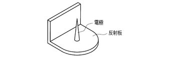
このような大気中におけるコロナ放電を利用したイオン発生に関し、図1A、図1B、図1Cに示すように、イオン発生電極1に印加されている電位と同電位を持った平板状の反射板2をイオン発生電極1の背後に設置することにより、イオン発生電極1で生成されたイオンを反発させて空間に放出するイオン発生素子が特許文献3に記載されている。
また、金属シャーシ内に設置されたイオン発生電極とシャーシの間に絶縁体で形成した反射体を設置することにより、イオン発生電極とシャーシ間の放電を防止し生成されたイオンを反発させて空間に放出するイオン発生素子構造が特許文献4に記載されている。
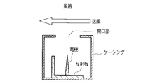
通常、イオン発生素子には高電圧が印加されており、また、イオン発生電極は針状に形成された尖端部を有していることから、人体への安全を考慮して、イオン発生素子は図2A、図2Bに示すようにイオン放出用の開口部を有するケーシング内に設置して使用される。また、前記イオン放出用の開口部は、人間が直接触れることができないようにするために、直径10mm以内であることが望ましい。
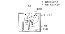
しかしながら、特許文献3に記載されているイオン発生素子では、図2A、図2Bに示すようにイオン発生電極をイオン放出用の開口部を有するケーシング内に設置した場合、風路に向かう方向、すなわち開口部に対して垂直方向の電界の指向性がよくないため、ケーシングのイオン放出用の開口部から、効率よく風路にイオンが放出されないという課題があった(図3参照)。
そこで、本発明の目的は、簡単な機構で、効率良く、イオン発生電極で生成されたイオンを、ケーシングの開口部から風路に放出することが可能なイオン発生素子を提供することである。
本発明に係るイオン発生素子は、針状に形成された尖端部を有し、高電圧を印加されることによって前記尖端部においてイオンを発生させるイオン発生電極と、イオン放出方向とは逆方向にイオン発生電極の尖端部と対向する位置に皿状の導電性材料でなる反射体とを備え、イオン発生電極と反射体とに同極性の電位が印加されることを特徴とする。
また、本発明に係るイオン発生素子においては、イオン発生電極の尖端部が平面視した反射体の図形の中心となるように形成されることが好ましい。
また、本発明に係るイオン発生素子においては、前記皿状の反射体は前記イオン発生電極を回転軸とする回転体であって、断面が円弧(半径が一定)であることが好ましい。
また、本発明に係るイオン発生素子においては、前記皿状の反射体は前記イオン発生電極を回転軸とする回転体であって、断面が、放物線であることが好ましい。
また、本発明に係るイオン発生素子においては、前記皿状の反射体は前記イオン発生電極を中心とする倒立多角錐体である、即ち断面が、台形であることが好ましい。
また、本発明に係るイオン発生素子においては、前記皿状の反射体は前記イオン発生電極を回転軸とする回転体であって、断面が、周縁部が隆起した平板であることが好ましい。
また、本発明に係るイオン発生素子においては、前記皿状の反射体の深さが、前記針状イオン発生電極の高さよりも浅いことが好ましい。
また、本発明に係るイオン発生素子においては、前記皿状の反射体が、前記針状イオン発生電極と機械構造上離れ、電気的にのみ接続されていてもよい。
本発明によれば、イオン発生電極をイオン放出用の開口部を有するケーシング内に設置した場合においても、風路に向かう方向、すなわち開口部に対して平板型の反射体と比較して垂直方向の指向性が鋭いため、ケーシングのイオン放出用の開口部から、効率よく風路にイオンを放出することが可能なイオン発生素子を提供することができる。
また、反射体をイオン発生電極を回転軸として形成する球体の一部とすることにより、イオン発生電極先端部と反射体との距離が前後、左右のどの方向も同じ長さとなり、イオン発生電極先端で発生したイオンが電極先端と反射体の両方から均等に反発力を受ける。これにより、風路に向かう方向の指向性が鋭いイオン発生素子を提供することができる。
また、反射体をイオン発生電極を回転軸とし、該回転軸の方向に長く伸びた球体の一部、または放物面とすることにより、放電電極先端部と反射体との距離が上下に比して前後、左右方向が近くなり、イオン発生電極先端で発生したイオンが反射体から強く反発力を受けイオンが収束される。このことにより、風路に向かう方向の指向性が非常に鋭いイオン発生素子を提供することができる。
また、反射体をイオン発生電極を中心軸とする倒立多角錐体とすることにより、反射体を球体の一部として形成するのと同様に、イオン発生電極先端で発生したイオンが反射体から強く反発力を受けイオンが収束される。このことにより、風路に向かう方向の指向性が鋭いイオン発生素子を提供することができる。
また、反射体をイオン発生電極を中心軸とし、周縁部が隆起した平板とすることにより、形状を単純化して反射体の形状自由度を高めつつ、イオン発生電極先端で発生したイオンが電界形成に大きく働く反射体の隆起した周縁部から強い反発力を受けてイオンが収束され、風路に向かう方向の指向性が鋭いイオン発生素子を提供することができる。
また、反射体をイオン発生電極を中心軸とし、周縁部が隆起した平板とすることにより、形状を単純化して反射体の形状自由度を高めつつ、イオン発生電極先端で発生したイオンが電界形成に大きく働く反射体の隆起した周縁部から強い反発力を受けてイオンが収束され、風路に向かう方向の指向性が鋭いイオン発生素子を提供することができる。
また、反射体の深さが針状イオン発生電極の高さよりも浅く、イオン発生電極の先端は反射体の上端よりも突出するようにすることにより、イオン発生電極先端からのイオン発生を反射体が抑制するという逆効果を無くし、指向性が鋭いイオン発生素子を提供することができる。
また、イオン発生電極は反射体と機械的に接続されずに形成することで、従来のイオン発生電極を使用し反射体のみを追加することが出来るため、特殊部品を調達する必要が無くなり製造コストを下げることができる。
以上のように、この発明に基づいたイオン発生素子によれば、高電圧部に触れることを防止するために、イオン発生電極をイオン放出用の開口部を有するケーシング内に設置した場合でも、風路に向かう方向、すなわち開口部に対して垂直方向の電界の指向性が鋭いため、効率よく風路にイオンを放出することが可能なイオン発生素子を提供することができる。
以下、この発明の実施の形態を図面に基づいて説明する。
(第1の実施形態)
図4A~図4Cは、本発明の第1実施形態に係るイオン発生素子の電極構造を示す図である。図4A~図4Cに示すイオン発生素子は、針状イオン発生電極1と導電性材料で形成される皿状の反射体4で構成されており、針状イオン発生電極1と皿状の反射体4は電気的に接続されている。皿状の反射体4はイオン発生電極1を回転軸とする回転体として形成される球体の一部であり、その断面形状は、円弧(半径が一定)となっている。また、針状イオン発生電極1は球体の直径を軸として皿状の反射体4から突出して配置される。さらに針状イオン発生電極1の上方から見るとき、皿状反射体4が形成する円の中心に設置される。また、この時の反射体4とイオン発生電極1との接点からイオン発生電極1の先端までの長さをイオン発生電極1の高さとする。
(第1の実施形態)
図4A~図4Cは、本発明の第1実施形態に係るイオン発生素子の電極構造を示す図である。図4A~図4Cに示すイオン発生素子は、針状イオン発生電極1と導電性材料で形成される皿状の反射体4で構成されており、針状イオン発生電極1と皿状の反射体4は電気的に接続されている。皿状の反射体4はイオン発生電極1を回転軸とする回転体として形成される球体の一部であり、その断面形状は、円弧(半径が一定)となっている。また、針状イオン発生電極1は球体の直径を軸として皿状の反射体4から突出して配置される。さらに針状イオン発生電極1の上方から見るとき、皿状反射体4が形成する円の中心に設置される。また、この時の反射体4とイオン発生電極1との接点からイオン発生電極1の先端までの長さをイオン発生電極1の高さとする。
外部電圧印加回路(図示せず)から前記イオン発生素子に高電圧を印加し、針状イオン発生電極1の先端付近の電界強度がある一定以上になるとコロナ放電を生じ、イオンが生成される。生成されたイオンは、針状イオン発生電極1周辺の電界の向きに沿って拡散し、空間に放出される。イオン発生素子に正の電圧を印加した場合は正イオンが反発して放出され、負の電圧を印加した場合は負イオンが反発して放出される。
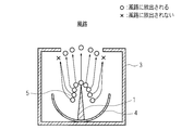
図5は、本発明の第1実施形態に係るイオン発生素子をイオン放出用の開口部を有するケーシング3内に設置した場合のイオン5の放出状態を示す概念図である。図5に示すように、イオン発生電極1と同電位で断面が円弧(半径rが一定)である皿状の反射体4によって、イオン5が創出されるイオン発生電極1先端部と反射体4との距離が前後、左右のどの方向も同じ長さとなり、イオン発生電極1先端で発生したイオン5が電極1と反射体4の両方から均等に反発力を受ける。平板型の反射板では放電電極に対して前後方向、左右方向が離れるほど、放電電極先端と反射板との距離が離れてしまうので、距離の2乗に反比例する反発力が大きく異なってしまう。これに対して球体などの形状によれば、前後左右方向どの方向からも同じ大きさで反発力を受けるのでイオン発生電極1からケーシングの開口部の間の、風路に向かう方向の電界の指向性が鋭くなっている。
したがって上記構成によれば、イオン発生素子をイオン放出用の開口部を有するケーシング3内に設置した場合においても、風路に向かう方向、すなわち開口部に対して垂直方向の電界の指向性が鋭いため、効率よく風路にイオン5を放出することが可能なイオン発生素子を提供することが可能となる。
上述した本発明に係るイオン発生素子は、空気調和機、除湿器、加湿器、空気清浄機、冷蔵庫、ファンヒータ、電子レンジ、洗濯乾燥機、掃除機、殺菌装置などの電気機器に搭載することが可能である。
係る電気機器には本発明に関わるイオン発生素子を複数備えて、各々正イオンと負イオンを発生するように構成することが出来る。また、ケーシングの開口部を通過した正イオン、負イオンの両方のイオンを空気中に送出する送出手段(例えば、送風ファン)を搭載するのがよい。
さらに、発生させる正イオンをH+(H2O)m(mは任意の自然数)、負イオンをO2-(H2O)n(nは任意の自然数)とするときには、このようなイオン発生装置を搭載する電気機器であれば、機器本来の機能に加えて、搭載したイオン発生素子から放出された正イオン、負イオンの作用により空気中のカビや菌を不活化してその増殖を抑制すること等ができ、室内環境を所望の雰囲気状態とすることが可能となる。
(第2の実施形態)
図6は、本発明の第2実施形態に係るイオン発生素子の電極構造、及び、該イオン発生素子をイオン放出用の開口部を有するケーシング内に設置した場合のイオン放出状態を示す側面断面図である。基本的な構造は第1実施形態と同じであるが、本実施形態では第1実施形態の球体の一部をなす反射体の代わりに放物面若しくは長球体の一部をなす反射体4とした。第1実施形態のときよりも、反射体4の前後方向、左右方向に加えて上下方向(針状電極の軸方向)が放電電極1に近くなりより強い反発力を呈する。このため、第1実施形態よりも収束された電界を形成することが可能となり、より強い志向性を持ってイオン5を放出することが出来る。
(第2の実施形態)
図6は、本発明の第2実施形態に係るイオン発生素子の電極構造、及び、該イオン発生素子をイオン放出用の開口部を有するケーシング内に設置した場合のイオン放出状態を示す側面断面図である。基本的な構造は第1実施形態と同じであるが、本実施形態では第1実施形態の球体の一部をなす反射体の代わりに放物面若しくは長球体の一部をなす反射体4とした。第1実施形態のときよりも、反射体4の前後方向、左右方向に加えて上下方向(針状電極の軸方向)が放電電極1に近くなりより強い反発力を呈する。このため、第1実施形態よりも収束された電界を形成することが可能となり、より強い志向性を持ってイオン5を放出することが出来る。
したがって上記構成によれば、イオン発生素子をイオン放出用の開口部を有するケーシング3内に設置した場合においても、風路に向かう方向、すなわち開口部に対して垂直方向の電界の指向性が鋭いため、効率よく風路にイオン5を放出することが可能なイオン発生素子を提供することが可能となる。
(検証)
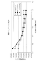
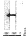
また、電磁界解析ソフトウェア「JMAG(JSOL社製)」を使用して、シミュレーションによって本発明に係るイオン発生素子の電極構造による効果の確認を行った。結果を表1及び図7、図8A、図8Bに示す。
また、電磁界解析ソフトウェア「JMAG(JSOL社製)」を使用して、シミュレーションによって本発明に係るイオン発生素子の電極構造による効果の確認を行った。結果を表1及び図7、図8A、図8Bに示す。
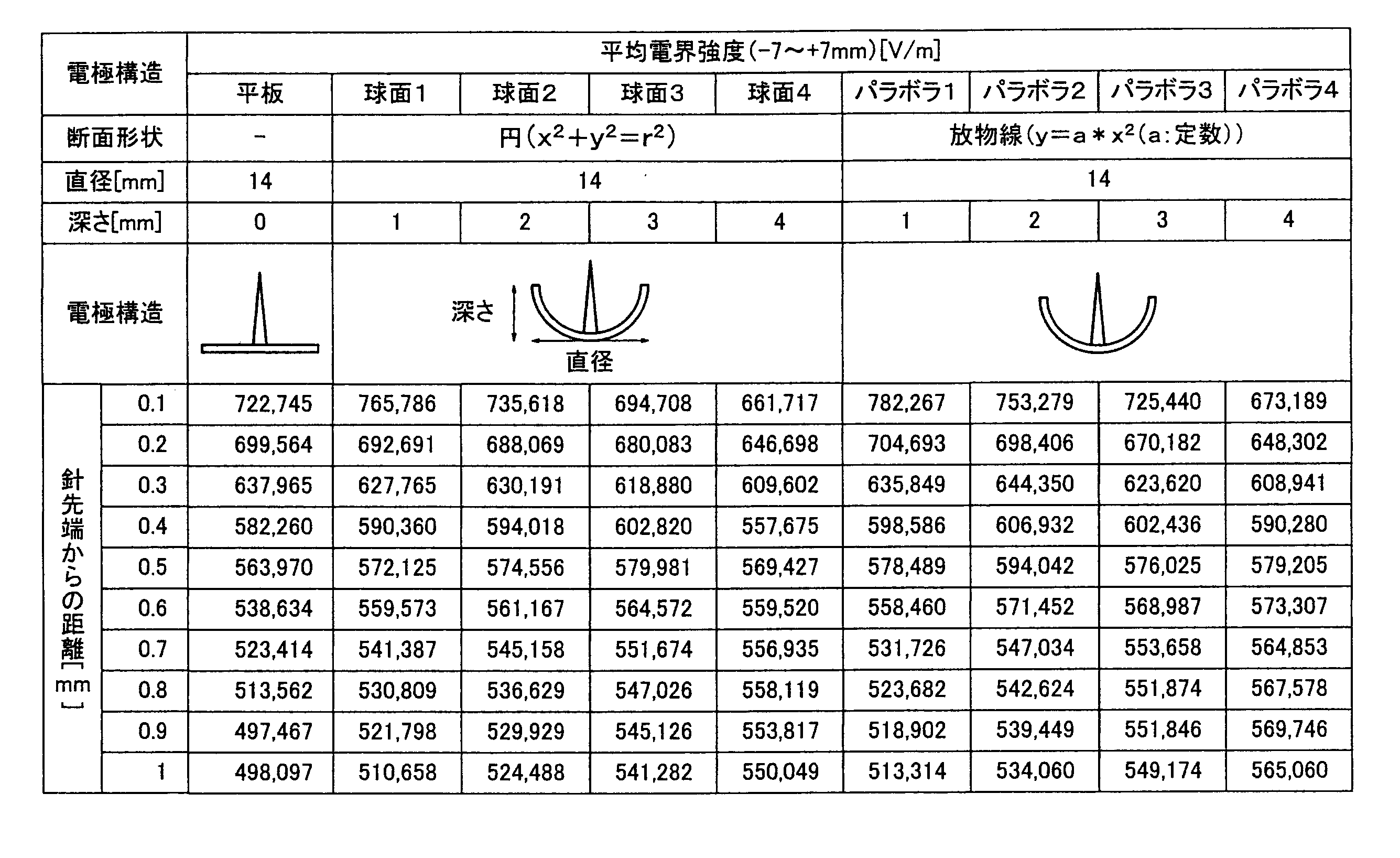
例えば、第1実施形態に係るイオン発生素子のイオン発生電極の長さを5mmに、皿状の反射体の直径を14mmに、深さを4mmにした場合、イオン発生電極の先端から1mm上方において、開口部に垂直な方向の電界の平均電界強度を確認すると、放電針の真下に円盤状反射板を設ける電極構造に比べ、約10%増加している結果が得られた。
また、例えば、第2実施形態に係るイオン発生素子のイオン発生電極の長さを5mmに、皿状の反射体の幅を14mmに、深さを4mmにした場合、イオン発生電極の先端から1mm上方において、開口部に垂直な方向の電界の平均電界強度を確認すると、従来の放電針の真下に円盤状反射板を設ける電極構造に比べ、約13%増加している結果が得られた。
表1において各々の電極構造で比較すると、針先から0.5mm以上離れた場所では、いずれも深さ4mmの場合が最も電界強度が高い結果となっている。
このことは、反射体の周縁部がエッジを形成しており電界集中が発生すること、および周縁部がイオン発生電極先端に近づくことに起因すると考えられる。イオン放出の指向性はイオン発生電極先端部及び反射体周縁部で発揮される反発力によって方向づけられる。
そのため、イオン発生電極の足元部分(反射体と接している部分)から反射体周縁部に至る中間部分の形状は必ずしも曲率を有する必要はないこと、さらには省略が可能なことが読み取れ、反射体はイオン発生電極と一体に形成されていることを必要とせず電気的な接続のみを要することが分かる。
(第3の実施形態)
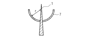
図9Aは本発明の第3実施形態に係るイオン発生素子の電極構造を示す上面図、図9Bは本発明の第3実施形態に係るイオン発生素子の電極構造を示す側面断面図、図9Cは本発明の第3実施形態に係るイオン発生素子の電極構造を示す斜視図である。本実施形態は基本的に第1実施形態と同じ構造であるが、反射体7を放電電極1の足元ではなく、途中に設けた。反射体7が空中に位置することとなり、第1実施形態と比較して基板等への取り付けに自由度が増える。効果は同様である。
図9Aは本発明の第3実施形態に係るイオン発生素子の電極構造を示す上面図、図9Bは本発明の第3実施形態に係るイオン発生素子の電極構造を示す側面断面図、図9Cは本発明の第3実施形態に係るイオン発生素子の電極構造を示す斜視図である。本実施形態は基本的に第1実施形態と同じ構造であるが、反射体7を放電電極1の足元ではなく、途中に設けた。反射体7が空中に位置することとなり、第1実施形態と比較して基板等への取り付けに自由度が増える。効果は同様である。
(第4の実施形態)
図10Aは本発明の第4実施形態に係るイオン発生素子の電極構造を示す上面図、図10Bは本発明の第4実施形態に係るイオン発生素子の電極構造を示す側面断面図、図10Cは本発明の第4実施形態に係るイオン発生素子の電極構造を示す斜視図である。上記検証を総合的に判断すると、反射体の中心部から周縁部に至る途中部分の影響は小さく、断面が必ずしも曲率を持っていることが条件にはならない。また、反射体がイオン発生電極を中心として前後左右の方向に均等であればいいので、反射体はイオン発生電極を回転軸とする回転体である必要もなく、回転体に近いものであればよい。つまり、回転体8はイオン発生電極1を中心とする複数の三角形の連続体である倒立多角錐体であれば同様の効果を得ることが出来るものと判断される。この例を図10A~図10Cに示す。図10A~図10Cでは16角形としたが多角形であれば多少の差はあるものの同様の効果が得られるものと考える。
図10Aは本発明の第4実施形態に係るイオン発生素子の電極構造を示す上面図、図10Bは本発明の第4実施形態に係るイオン発生素子の電極構造を示す側面断面図、図10Cは本発明の第4実施形態に係るイオン発生素子の電極構造を示す斜視図である。上記検証を総合的に判断すると、反射体の中心部から周縁部に至る途中部分の影響は小さく、断面が必ずしも曲率を持っていることが条件にはならない。また、反射体がイオン発生電極を中心として前後左右の方向に均等であればいいので、反射体はイオン発生電極を回転軸とする回転体である必要もなく、回転体に近いものであればよい。つまり、回転体8はイオン発生電極1を中心とする複数の三角形の連続体である倒立多角錐体であれば同様の効果を得ることが出来るものと判断される。この例を図10A~図10Cに示す。図10A~図10Cでは16角形としたが多角形であれば多少の差はあるものの同様の効果が得られるものと考える。
(第5の実施形態)
図11Aは本発明の第5実施形態に係るイオン発生素子の電極構造を示す上面図、図11Bは本発明の第5実施形態に係るイオン発生素子の電極構造を示す側面断面図、図11Cは本発明の第5実施形態に係るイオン発生素子の電極構造を示す斜視図である。反射体9の最下部に開口部を設けて、イオン発生電極1をこの開口を貫通する状態で設置した例であり、同様の効果が得られるものと考える。上記検証を総合的に判断すると、反射体の中心部から周縁部に至る途中部分の影響は小さく省略可能であると考えられ、針尖端と反射体周縁部相対的な距離のみ確保するために、イオン発生電極1を固定する基板10と異なる基板10に反射体9を設置した。実施形態3と同様の効果が期待できる。
図11Aは本発明の第5実施形態に係るイオン発生素子の電極構造を示す上面図、図11Bは本発明の第5実施形態に係るイオン発生素子の電極構造を示す側面断面図、図11Cは本発明の第5実施形態に係るイオン発生素子の電極構造を示す斜視図である。反射体9の最下部に開口部を設けて、イオン発生電極1をこの開口を貫通する状態で設置した例であり、同様の効果が得られるものと考える。上記検証を総合的に判断すると、反射体の中心部から周縁部に至る途中部分の影響は小さく省略可能であると考えられ、針尖端と反射体周縁部相対的な距離のみ確保するために、イオン発生電極1を固定する基板10と異なる基板10に反射体9を設置した。実施形態3と同様の効果が期待できる。
(第6の実施形態)
図12Aは本発明の第6実施形態に係るイオン発生素子の電極構造を示す上面図、図12Bは本発明の第6実施形態に係るイオン発生素子の電極構造を示す側面断面図、図12Cは本発明の第6実施形態に係るイオン発生素子の電極構造を示す斜視図である。本実施形態は基本的に第1実施形態と同じ構造であるが、反射体2を平板型としながらも周縁部2aを少し立ち上げた形状とした。検証により反射体2の周縁部2aとイオン発生電極1先端部が電界形成に大きく働くことから、形状を単純化したものである。第1実施形態と比較して反射板2の形状自由度が増える。反射板2の周縁部2aとイオン発生電極1との距離が他の例と同じように配置されることで同様の効果が得られる。
図12Aは本発明の第6実施形態に係るイオン発生素子の電極構造を示す上面図、図12Bは本発明の第6実施形態に係るイオン発生素子の電極構造を示す側面断面図、図12Cは本発明の第6実施形態に係るイオン発生素子の電極構造を示す斜視図である。本実施形態は基本的に第1実施形態と同じ構造であるが、反射体2を平板型としながらも周縁部2aを少し立ち上げた形状とした。検証により反射体2の周縁部2aとイオン発生電極1先端部が電界形成に大きく働くことから、形状を単純化したものである。第1実施形態と比較して反射板2の形状自由度が増える。反射板2の周縁部2aとイオン発生電極1との距離が他の例と同じように配置されることで同様の効果が得られる。
本発明によれば、針状の放電電極を有するイオン発生素子において発生したイオンを強い志向性を持って放出させることが可能となり、特に針状電極が安全のためにケース内から突出しないように構成されたイオン発生装置においてイオンの有効な送出が出来る。
また、本発明は上述の実施形態に限定されるものではなく、本発明の趣旨を逸脱しない範囲において各部の構成等を適宜に変更して実施することも可能である。
1 針状イオン発生電極
2 平板状の反射板
2a 隆起部
3 開口部を有するケーシング
4 断面が円弧(半径が一定)である皿状の反射体
5 イオン
6 断面が放物線である皿状の反射体
7 イオン発生電極と一体に形成された皿状の反射体
8 断面が台形である皿状の反射体
9 底部に開口を持つ皿状の反射体
10 基板
2 平板状の反射板
2a 隆起部
3 開口部を有するケーシング
4 断面が円弧(半径が一定)である皿状の反射体
5 イオン
6 断面が放物線である皿状の反射体
7 イオン発生電極と一体に形成された皿状の反射体
8 断面が台形である皿状の反射体
9 底部に開口を持つ皿状の反射体
10 基板
Claims (8)
- 針状に形成された尖端部を有し、高電圧を印加されることによって前記尖端部においてイオンを発生させるイオン発生電極を備えたイオン発生素子において、
イオン放出方向とは逆方向に前記イオン発生電極の尖端部と対向する位置に皿状の導電性材料でなる反射体を備え、前記イオン発生電極と前記反射体とに同極性の電位が印加されることを特徴とするイオン発生素子。 - 前記イオン発生電極の尖端部が平面視した前記反射体の図形の中心となるように形成されることを特徴とする請求項1に記載のイオン発生素子。
- 前記皿状の反射体は前記イオン発生電極を回転軸とする回転体であって、断面が円弧であることを特徴とする、請求項2に記載のイオン発生素子。
- 前記皿状の反射体は前記イオン発生電極を回転軸とする回転体であって、断面が放物線であることを特徴とする、請求項2に記載のイオン発生素子。
- 前記皿状の反射体は前記イオン発生電極を中心とする倒立多角錐体であることを特徴とする、請求項2に記載のイオン発生素子。
- 前記皿状の反射体は前記イオン発生電極を回転軸とする回転体であって、断面が周縁部が隆起した平板であることを特徴とする、請求項2に記載のイオン発生素子。
- 前記イオン発生電極と前記皿状の反射体とが機械構造上接続されず、電気的にのみ接続されることを特徴とする請求項1~6に記載のイオン発生素子。
- 前記皿状の反射体の深さが、前記イオン発生電極の高さよりも浅いことを特徴とする請求項1から7に記載のイオン発生素子。
Applications Claiming Priority (2)
| Application Number | Priority Date | Filing Date | Title |
|---|---|---|---|
| JP2011033028A JP2012174398A (ja) | 2011-02-18 | 2011-02-18 | イオン発生素子 |
| JP2011-033028 | 2011-02-18 |
Publications (1)
| Publication Number | Publication Date |
|---|---|
| WO2012111372A1 true WO2012111372A1 (ja) | 2012-08-23 |
Family
ID=46672314
Family Applications (1)
| Application Number | Title | Priority Date | Filing Date |
|---|---|---|---|
| PCT/JP2012/050907 Ceased WO2012111372A1 (ja) | 2011-02-18 | 2012-01-18 | イオン発生素子 |
Country Status (2)
| Country | Link |
|---|---|
| JP (1) | JP2012174398A (ja) |
| WO (1) | WO2012111372A1 (ja) |
Families Citing this family (2)
| Publication number | Priority date | Publication date | Assignee | Title |
|---|---|---|---|---|
| JP6009233B2 (ja) * | 2012-06-08 | 2016-10-19 | シャープ株式会社 | イオン発生装置およびイオン発生装置を備えた電気機器 |
| JP6103830B2 (ja) * | 2012-06-22 | 2017-03-29 | シャープ株式会社 | イオン発生装置およびイオン発生装置を備えた電気機器 |
Citations (5)
| Publication number | Priority date | Publication date | Assignee | Title |
|---|---|---|---|---|
| JPS59147154U (ja) * | 1983-03-22 | 1984-10-01 | 株式会社リコー | 電子写真装置のコロナ帯電器 |
| JP2002043092A (ja) * | 2000-07-19 | 2002-02-08 | Takayanagi Kenkyusho:Kk | バータイプ除電器 |
| JP2004109428A (ja) * | 2002-09-18 | 2004-04-08 | Ricoh Co Ltd | 感光体帯電装置 |
| JP2004160383A (ja) * | 2002-11-14 | 2004-06-10 | Kyoritsu Denki Sangyo Kk | 空気清浄活性器 |
| JP2009170381A (ja) * | 2008-01-21 | 2009-07-30 | Ai Seiko:Kk | 除電装置 |
-
2011
- 2011-02-18 JP JP2011033028A patent/JP2012174398A/ja active Pending
-
2012
- 2012-01-18 WO PCT/JP2012/050907 patent/WO2012111372A1/ja not_active Ceased
Patent Citations (5)
| Publication number | Priority date | Publication date | Assignee | Title |
|---|---|---|---|---|
| JPS59147154U (ja) * | 1983-03-22 | 1984-10-01 | 株式会社リコー | 電子写真装置のコロナ帯電器 |
| JP2002043092A (ja) * | 2000-07-19 | 2002-02-08 | Takayanagi Kenkyusho:Kk | バータイプ除電器 |
| JP2004109428A (ja) * | 2002-09-18 | 2004-04-08 | Ricoh Co Ltd | 感光体帯電装置 |
| JP2004160383A (ja) * | 2002-11-14 | 2004-06-10 | Kyoritsu Denki Sangyo Kk | 空気清浄活性器 |
| JP2009170381A (ja) * | 2008-01-21 | 2009-07-30 | Ai Seiko:Kk | 除電装置 |
Also Published As
| Publication number | Publication date |
|---|---|
| JP2012174398A (ja) | 2012-09-10 |
Similar Documents
| Publication | Publication Date | Title |
|---|---|---|
| JP4747328B2 (ja) | イオン発生装置および電気機器 | |
| JP5559144B2 (ja) | 局地的な大気改変方法および装置 | |
| CN108026633A (zh) | 处理装置和准直器 | |
| KR102190030B1 (ko) | 플라즈마 발생 장치 | |
| CN110506373A (zh) | 放电装置以及电气设备 | |
| WO2012111372A1 (ja) | イオン発生素子 | |
| CN108883423B (zh) | 离子发生器装置支架 | |
| JP2020168597A (ja) | 帯電装置及び集塵装置 | |
| US8000080B2 (en) | Particle trap | |
| CN101501811A (zh) | X射线管以及x射线管的离子偏转和收集装置的电压供应方法 | |
| JP2021501034A (ja) | イオンフロー加速器を備えた、特に蚊から保護するためのイオナイザ | |
| US20100110602A1 (en) | Electric field control methods and apparatuses for corona wind fans | |
| JP6170324B2 (ja) | イオン発生装置 | |
| WO2024111049A1 (ja) | 空気清浄機および空気調和装置 | |
| JP6041615B2 (ja) | 送風機器 | |
| CN112864812B (zh) | 一种双极离子发生器及空气净化装置 | |
| JP2014108315A (ja) | 微生物不活化デバイス | |
| CN114728293B (zh) | 颗粒消除器 | |
| JP2016066463A (ja) | イオン発生装置及びそれを備えた装置 | |
| JP2002198160A (ja) | マイナスイオン発生器 | |
| EP2434924B1 (en) | Metal microparticle generator | |
| US12176684B2 (en) | Discharge device | |
| JP2011018477A (ja) | 放電電極、イオン発生素子および電気機器 | |
| WO2012032973A1 (ja) | イオン発生装置 | |
| JP2007122890A (ja) | イオン発生素子およびそれを備えた電気機器 |
Legal Events
| Date | Code | Title | Description |
|---|---|---|---|
| 121 | Ep: the epo has been informed by wipo that ep was designated in this application |
Ref document number: 12746527 Country of ref document: EP Kind code of ref document: A1 |
|
| NENP | Non-entry into the national phase |
Ref country code: DE |
|
| 122 | Ep: pct application non-entry in european phase |
Ref document number: 12746527 Country of ref document: EP Kind code of ref document: A1 |