実施の形態1に係る液晶表示装置(面光源装置を含む)の一例の構成を概略的に示す断面図である。FIG. 3 is a cross-sectional view schematically showing a configuration of an example of a liquid crystal display device (including a surface light source device) according to Embodiment 1.
実施の形態1に係る面光源装置の光路変更部材の構成を概略的に示す斜視図である。3 is a perspective view schematically showing a configuration of an optical path changing member of the surface light source device according to Embodiment 1. FIG.
実施の形態1に係る面光源装置を液晶パネル側から見た概略的な平面図である。It is the schematic plan view which looked at the surface light source device which concerns on Embodiment 1 from the liquid crystal panel side.
実施の形態1に係る面光源装置を液晶表示装置の背面側から見た概略的な背面図である。It is the schematic rear view which looked at the surface light source device which concerns on Embodiment 1 from the back side of the liquid crystal display device.
実施の形態1に係る面光源装置の面発光導光板の他の例を示す概略的な背面図である。It is a schematic rear view which shows the other example of the surface emitting light-guide plate of the surface light source device which concerns on Embodiment 1. FIG.
実施の形態1に係る第1の光線の面発光導光板内での挙動を示す概略的な説明図である。It is a schematic explanatory drawing which shows the behavior within the surface emitting light-guide plate of the 1st light ray concerning Embodiment 1. FIG.
実施の形態1に係る第1の光線の面発光導光板内における角度強度分布を示す特性図である。It is a characteristic view which shows angular intensity distribution in the surface emitting light-guide plate of the 1st light ray which concerns on Embodiment 1. FIG.
実施の形態1に係る第1の光線及び第2の光線の面発光導光板内における角度強度分布を示す特性図である。It is a characteristic view which shows the angle intensity distribution in the surface emitting light-guide plate of the 1st light ray which concerns on Embodiment 1, and a 2nd light ray.
実施の形態1に係る液晶表示装置の制御系の構成を概略的に示すブロック図である。3 is a block diagram schematically showing a configuration of a control system of the liquid crystal display device according to Embodiment 1. FIG.
実施の形態2に係る液晶表示装置(面光源装置を含む)の一例の構成を概略的に示す断面図である。It is sectional drawing which shows roughly the structure of an example of the liquid crystal display device (including surface light source device) which concerns on Embodiment 2. FIG.
実施の形態2に係る液晶表示装置(面光源装置を含む)の他の例の構成を概略的に示す断面図である。It is sectional drawing which shows schematically the structure of the other example of the liquid crystal display device (including surface light source device) which concerns on Embodiment 2. FIG.
実施の形態3に係る液晶表示装置(面光源装置を含む)の一例の構成を概略的に示す断面図である。It is sectional drawing which shows schematically the structure of an example of the liquid crystal display device (including a surface light source device) concerning Embodiment 3.
実施の形態3に係る液晶表示装置(面光源装置を含む)の他の例の構成を概略的に示す断面図である。It is sectional drawing which shows schematically the structure of the other example of the liquid crystal display device (including a surface light source device) concerning Embodiment 3.
実施の形態3に係る液晶表示装置(面光源装置を含む)の更に他の例の構成を概略的に示す断面図である。It is sectional drawing which shows schematically the structure of the further another example of the liquid crystal display device (including surface light source device) which concerns on Embodiment 3. FIG.
実施の形態1.
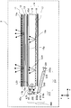
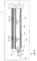
図1は、実施の形態1に係る液晶表示装置1(面光源装置100を含む)の一例の構成を概略的に示す断面図である。また、図2は、図1に示される面光源装置100の光反射部材としてのシリンドリカルミラー102の構成を概略的に示す斜視図である。図3は、図1に示される面光源装置100を液晶パネル11側から見た概略的な平面図であり、図4は、図1に示される面光源装置100を液晶表示装置1の背面側から見た概略的な背面図である。
Embodiment 1 FIG.
FIG. 1 is a cross-sectional view schematically showing a configuration of an example of the liquid crystal display device 1 (including the surface light source device 100) according to the first embodiment. 2 is a perspective view schematically showing a configuration of a cylindrical mirror 102 as a light reflecting member of the surface light source device 100 shown in FIG. 3 is a schematic plan view of the surface light source device 100 shown in FIG. 1 as viewed from the liquid crystal panel 11 side. FIG. 4 shows the surface light source device 100 shown in FIG. It is the schematic rear view seen from.
液晶表示装置1は、矩形の表示面11a及びその反対側の背面11bを持つ液晶表示素子(以下「液晶パネル」ともいう。)11を備えた透過型の液晶表示装置1である。説明を容易にするために、各図中に、xyz直交座標系の座標軸を示す。以下の説明において、液晶パネル11の表示面11aの短辺方向をy軸方向(図1が描かれている紙面に垂直な方向)とし、液晶パネル11の表示面11aの長辺方向をx軸方向(図1において左右方向)とし、xy平面に垂直な方向をz軸方向(図1における上下方向)とする。また、図1において、左から右に向かう方向を、x軸の正方向(+x軸方向)とし、その反対方向を、x軸の負方向(-x軸方向)とする。また、図1が描かれている紙面の手前から紙面に向かう方向を、y軸の正方向(+y軸方向)とし、その反対方向を、y軸の負方向(-y軸方向)とする。さらに、図1において、下から上に向かう方向を、z軸の正方向(+z軸方向)とし、その反対方向を、z軸の負方向(-z軸方向)とする。
The liquid crystal display device 1 is a transmissive liquid crystal display device 1 including a liquid crystal display element (hereinafter also referred to as “liquid crystal panel”) 11 having a rectangular display surface 11a and a back surface 11b on the opposite side. For ease of explanation, the coordinate axes of the xyz orthogonal coordinate system are shown in each figure. In the following description, the short side direction of the display surface 11a of the liquid crystal panel 11 is defined as the y-axis direction (direction perpendicular to the paper surface on which FIG. 1 is drawn), and the long side direction of the display surface 11a of the liquid crystal panel 11 is defined as the x axis. Direction (left and right direction in FIG. 1), and a direction perpendicular to the xy plane is a z-axis direction (up and down direction in FIG. 1). In FIG. 1, the direction from left to right is the positive direction of the x axis (+ x axis direction), and the opposite direction is the negative direction of the x axis (−x axis direction). In addition, the direction from the front of the paper surface on which FIG. 1 is drawn to the paper surface is the positive direction of the y axis (+ y axis direction), and the opposite direction is the negative direction of the y axis (−y axis direction). Further, in FIG. 1, the direction from the bottom to the top is the positive direction of the z-axis (+ z-axis direction), and the opposite direction is the negative direction of the z-axis (−z-axis direction).
図1に示されるように、実施の形態1に係る液晶表示装置1は、透過型の液晶パネル11、第1の光学シート12、第2の光学シート13及びバックライトユニット100を有している。バックライトユニット100は、第2の光学シート13及び第1の光学シート12を通して液晶パネル11の背面11bに光を照射する面光源装置である。これらの構成要素11,12,13,100は、-z軸方向に順に配列されている。
As shown in FIG. 1, the liquid crystal display device 1 according to Embodiment 1 includes a transmissive liquid crystal panel 11, a first optical sheet 12, a second optical sheet 13, and a backlight unit 100. . The backlight unit 100 is a surface light source device that irradiates light to the back surface 11 b of the liquid crystal panel 11 through the second optical sheet 13 and the first optical sheet 12. These components 11, 12, 13, and 100 are arranged in order in the −z-axis direction.
液晶パネル11の表示面11aは、xy平面に平行な面である。液晶パネル11の液晶層は、xy平面に平行な方向に広がる面状の構造を有している。液晶パネル11の表示面11aは、通常、矩形であり、表示面11aの隣接する2辺(実施の形態1においては、y軸方向の短辺とx軸方向の長辺)は、直交している。ただし、表示面11aの形状は、他の形状であってもよい。
The display surface 11a of the liquid crystal panel 11 is a surface parallel to the xy plane. The liquid crystal layer of the liquid crystal panel 11 has a planar structure that spreads in a direction parallel to the xy plane. The display surface 11a of the liquid crystal panel 11 is usually rectangular, and two adjacent sides of the display surface 11a (in Embodiment 1, the short side in the y-axis direction and the long side in the x-axis direction) are orthogonal to each other. Yes. However, the shape of the display surface 11a may be other shapes.
図1に示されるように、面光源装置100は、薄板状の面発光導光板15、光反射シート17、第2の光源18、第1の光源101及びシリンドリカルミラー102を有している。シリンドリカルミラー102は、光路変更部材としての機能を有している。ここで、第2の光源18及び第1の光源101は、第2の光源18から第2の光線が出射された直後における第2の光線の角度強度分布は、第1の光源101から第1の光線が出射された直後における第1の光線の角度強度分布よりも広くなるように選ばれる。
As shown in FIG. 1, the surface light source device 100 includes a thin plate-like surface light-emitting light guide plate 15, a light reflection sheet 17, a second light source 18, a first light source 101, and a cylindrical mirror 102. The cylindrical mirror 102 has a function as an optical path changing member. Here, the second light source 18 and the first light source 101 have an angular intensity distribution of the second light beam immediately after the second light beam is emitted from the second light source 18. Is selected to be wider than the angular intensity distribution of the first light beam immediately after the first light beam is emitted.
第2の光源18の第2の光線L11を出射する発光部は、面発光導光板15の光入射面(側面)15cに対向配置されている。第2の光源18は、1つ以上、望ましくは、複数の発光ダイオード(LED)素子をy軸方向に等間隔で配列した光源装置である。第2の光源18は、光入射面15c(第3の面)のz軸方向の長さの範囲内に配置されている。すなわち、第2の光源18は、面発光導光板15の厚みの範囲内に配置されることが望ましい。図1には、第2の光源18から出射した第2の光線L11が、直接、面発光導光板15の光入射面15cに入射する場合が示されている。しかし、レンズなどの他の光学素子を介して第2の光線L11を光入射面15cに入射させてもよい。なお、出射とは、ある方向に向けて光を発することである。
The light emitting unit that emits the second light beam L11 of the second light source 18 is disposed to face the light incident surface (side surface) 15c of the surface light emitting light guide plate 15. The second light source 18 is a light source device in which one or more, preferably a plurality of light emitting diode (LED) elements are arranged at equal intervals in the y-axis direction. The second light source 18 is disposed within the range of the length in the z-axis direction of the light incident surface 15c (third surface). That is, it is desirable that the second light source 18 is disposed within the thickness range of the surface light-emitting light guide plate 15. FIG. 1 shows a case where the second light beam L11 emitted from the second light source 18 is directly incident on the light incident surface 15c of the surface light-emitting light guide plate 15. However, the second light beam L11 may be incident on the light incident surface 15c via another optical element such as a lens. Note that emission refers to emitting light in a certain direction.
第1の光源101は、面発光導光板15の表面15aの反対側である背面15b側(-z軸方向)に配置されている。第1の光源101は、1つ以上、望ましくは、複数のレーザ発光素子をy軸方向に等間隔で配列した光源装置である。第1の光源101の第1の光線L12を出射する発光部は、シリンドリカルミラー102の光反射面102aに対向配置されている。
The first light source 101 is disposed on the back surface 15b side (−z-axis direction) opposite to the surface 15a of the surface light-emitting light guide plate 15. The first light source 101 is a light source device in which one or more, preferably a plurality of laser light emitting elements are arranged at equal intervals in the y-axis direction. The light emitting unit that emits the first light beam L <b> 12 of the first light source 101 is disposed to face the light reflecting surface 102 a of the cylindrical mirror 102.
シリンドリカルミラー102の光反射面102aは、面発光導光板15の光入射面15cとも対向して配置されている。図1及び図2に示したように、光反射面102aをxz平面で切断した場合の断面形状は、光入射面15c側に凹形の円弧形状である。また、光反射面102aをxy平面で切断され場合の断面形状は、y軸方向に延びる直線状である。なお、光反射面102aは、シリンドリカルミラー102の光反射面である。光入射面15cは、面発光導光板15の端面である。また、シリンドリカルミラー102は、第1の光反射部材である。
The light reflecting surface 102a of the cylindrical mirror 102 is also arranged to face the light incident surface 15c of the surface light-emitting light guide plate 15. As shown in FIGS. 1 and 2, the cross-sectional shape when the light reflecting surface 102a is cut along the xz plane is a concave arc shape on the light incident surface 15c side. The cross-sectional shape when the light reflecting surface 102a is cut along the xy plane is a straight line extending in the y-axis direction. The light reflecting surface 102 a is a light reflecting surface of the cylindrical mirror 102. The light incident surface 15 c is an end surface of the surface emitting light guide plate 15. The cylindrical mirror 102 is a first light reflecting member.
図1及び図2に示した例では、実施の形態1におけるシリンドリカルミラー102は、離心率0.47の楕円の4分の1筒形状である。その楕円の長軸は、x軸と平行である。また、シリンドリカルミラー102は、その凹面側を光反射面102aとしている。光反射面102aは、円筒又は楕円筒を、その軸(y軸と平行な軸)を通る平面でn個に分割したn分の1円筒形状(nは、1より大きい数)とすることができる。
In the example shown in FIGS. 1 and 2, the cylindrical mirror 102 in Embodiment 1 has an elliptical quarter cylinder shape with an eccentricity of 0.47. The major axis of the ellipse is parallel to the x axis. Further, the cylindrical mirror 102 has a concave surface side as a light reflecting surface 102a. The light reflecting surface 102a may have a cylindrical shape of 1 / n (n is a number greater than 1) obtained by dividing a cylinder or an elliptic cylinder into n by a plane passing through the axis (axis parallel to the y axis). it can.
シリンドリカルミラー102の光反射面102aには、例えば、光を反射する金属膜の層が設けられている。光反射面102aの接線の方向は、各位置に応じて異なる。そのため、光束(光線の束であり、大きさを有する光線)が光反射面102aに入射すると、各光線は、入射位置に応じて異なる出射角度で反射する。
The light reflecting surface 102a of the cylindrical mirror 102 is provided with a metal film layer that reflects light, for example. The direction of the tangent line of the light reflecting surface 102a differs depending on each position. Therefore, when a light beam (a light beam having a size and having a size) is incident on the light reflecting surface 102a, each light beam is reflected at a different emission angle depending on the incident position.
シリンドリカルミラー102の基材は、アクリル樹脂(例えば、PMMA)である。光反射面102aは、例えば、アルミニウムを蒸着した面である。ただし、シリンドリカルミラー102を構成する材料及び形状は、この例に限定されない。例えば、基材に加工性に優れた他の樹脂や金属を採用してもよい。また、光反射面102aに蒸着する金属膜に、銀又は金などの反射率の高い他の金属を採用してもよい。
The base material of the cylindrical mirror 102 is an acrylic resin (for example, PMMA). The light reflecting surface 102a is, for example, a surface on which aluminum is deposited. However, the material and the shape which comprise the cylindrical mirror 102 are not limited to this example. For example, you may employ | adopt other resin and metal excellent in workability for a base material. Moreover, you may employ | adopt other metals with high reflectance, such as silver or gold, for the metal film vapor-deposited on the light reflection surface 102a.
面発光導光板15は、表面(第1の面)15a、背面15b(第2の面)及び複数の側面(第3の面)を有する板状の光学部材である。背面15bは、表面15aと対向する面である。複数の側面は、表面15aの辺(端部)と背面15bの辺(端部)とを繋ぐ細長い面である。面発光導光板15は、透光性の光学部材である。また、面発光導光板15は、背面15b上に複数の微小光学素子16を有している。図1に示されるように、実施の形態1においては、表面15aと背面15bとは、略平行である。また表面15a及び背面15bの面は、xy平面と平行である。以後、表面15a及び背面15bと平行な面を面発光導光板15の基準平面と呼ぶ。
The surface-emitting light guide plate 15 is a plate-like optical member having a front surface (first surface) 15a, a back surface 15b (second surface), and a plurality of side surfaces (third surface). The back surface 15b is a surface facing the surface 15a. The plurality of side surfaces are elongated surfaces that connect the side (end portion) of the surface 15a and the side (end portion) of the back surface 15b. The surface-emitting light guide plate 15 is a translucent optical member. The surface light-emitting light guide plate 15 has a plurality of micro optical elements 16 on the back surface 15b. As shown in FIG. 1, in the first embodiment, the front surface 15a and the back surface 15b are substantially parallel. The surfaces of the front surface 15a and the back surface 15b are parallel to the xy plane. Hereinafter, a plane parallel to the front surface 15 a and the back surface 15 b is referred to as a reference plane of the surface light-emitting light guide plate 15.
面発光導光板15と微小光学素子16とは、光学部材14を構成している。微小光学素子16は、面発光導光板15の光入射面15cから入射した光線を、表面15a側に向ける機能を有する。微小光学素子16の占める面積が広い領域では、表面15aに向かう照明光L14の量が多くなる。微小光学素子16の占める面積が広い領域とは、例えば、1つの微小光学素子16が広い領域(後述の図4の場合)や、微小光学素子16の配列密度が高い領域(後述の図5の場合)のことである。このため、面発光導光板15の光入射面15cから+x方向に離れるほど、微小光学素子16が占める面積が増加するように、微小光学素子16の単位面積当たりの個数及び形状を決定することが望ましい。
The surface-emitting light guide plate 15 and the micro optical element 16 constitute an optical member 14. The micro optical element 16 has a function of directing light incident from the light incident surface 15c of the surface light-emitting light guide plate 15 toward the surface 15a. In a region where the area occupied by the micro optical element 16 is large, the amount of illumination light L14 directed toward the surface 15a increases. The area occupied by the micro optical element 16 is, for example, an area where one micro optical element 16 is wide (in the case of FIG. 4 described later), or an area where the arrangement density of the micro optical elements 16 is high (described below in FIG. 5). Case). For this reason, the number and shape per unit area of the micro optical elements 16 can be determined so that the area occupied by the micro optical elements 16 increases as the distance from the light incident surface 15c of the surface light-emitting light guide plate 15 increases in the + x direction. desirable.
なお、図1及び図4に示す微小光学素子16の形状及び配置位置における個数は、一例である。図1及び図4に示す微小光学素子16は、光入射面15cから+x方向に離れるほど微小光学素子16の形状を大きくすることで、微小光学素子16の占める面積を大きくしている。図5に示す微小光学素子16は、微小光学素子16の大きさは、同じで、光入射面15cから+x方向に離れるほど微小光学素子16の配列密度(単位面積当たりの個数)を高くしている。これらように、微小光学素子16の占める面積は、微小光学素子16の単位面積当たりの個数及び形状により変えることができる。
Note that the shape and the number of the micro optical elements 16 shown in FIGS. 1 and 4 are only examples. The micro optical element 16 shown in FIG. 1 and FIG. 4 increases the area occupied by the micro optical element 16 by increasing the shape of the micro optical element 16 away from the light incident surface 15c in the + x direction. The micro optical element 16 shown in FIG. 5 has the same size, and the arrangement density (number per unit area) of the micro optical elements 16 increases as the distance from the light incident surface 15c in the + x direction increases. Yes. As described above, the area occupied by the micro optical element 16 can be changed depending on the number and shape of the micro optical element 16 per unit area.
面発光導光板15の表面15aは、液晶パネル11の表示面11aに対して平行に配置されている。面発光導光板15は、光入射面15cから面発光導光板15の中心に向けて所定の長さの角度強度分布整形領域15e(第1の領域)を備えている。例えば、角度強度分布整形領域15eは、光入射面15cから+x軸方向に20mmの領域である。角度強度分布整形領域15eにおいて、面発光導光板15は、表面15a及び背面15bともに微小光学素子16のような光学構造を有さず、空気層に面している。光入射面15cから角度強度分布整形領域15eに入射した光は、空気層との界面で全反射しながら+x軸方向に進む(伝播する)。空気層とは、光学部材を取り巻く空気のことである。空気層との界面とは、空気層と接している表面15a、背面15bなどである。面発光導光板15の角度強度分布整形領域15eは、光入射面15cから入射した第1の光線を伝播させながら第1の光線の角度強度分布を広くする領域である。面発光導光板15は、面発光導光板15の角度強度分布整形領域15eを通過した直後における第1の光線の角度強度分布と、角度強度分布整形領域15eを通過した直後における第2の光線の角度強度分布とが略等しくなるように構成されることが望ましい。
The surface 15 a of the surface light emitting light guide plate 15 is arranged in parallel to the display surface 11 a of the liquid crystal panel 11. The surface light-emitting light guide plate 15 includes an angle intensity distribution shaping region 15e (first region) having a predetermined length from the light incident surface 15c toward the center of the surface light-emitting light guide plate 15. For example, the angular intensity distribution shaping region 15e is a region 20 mm away from the light incident surface 15c in the + x axis direction. In the angle intensity distribution shaping region 15e, the surface light-emitting light guide plate 15 does not have an optical structure like the micro optical element 16 on the front surface 15a and the back surface 15b, and faces the air layer. The light incident on the angular intensity distribution shaping region 15e from the light incident surface 15c proceeds (propagates) in the + x-axis direction while being totally reflected at the interface with the air layer. The air layer is air surrounding the optical member. The interface with the air layer is the front surface 15a, the back surface 15b, or the like in contact with the air layer. The angular intensity distribution shaping region 15e of the surface light-emitting light guide plate 15 is a region that widens the angular intensity distribution of the first light beam while propagating the first light beam incident from the light incident surface 15c. The surface light-emitting light guide plate 15 has an angular intensity distribution of the first light beam immediately after passing through the angle intensity distribution shaping region 15e of the surface light-emitting light guide plate 15 and a second light ray immediately after passing through the angle intensity distribution shaping region 15e. It is desirable that the angular intensity distribution be configured to be substantially equal.
面発光導光板15は、領域15f(第2の領域)の背面15bに微小光学素子16を有している。領域15fは、角度強度分布整形領域15eの+x軸方向に隣接する領域である。したがって、角度強度分布整形領域15eは、光入射面15cと領域15fとの間に配置される。背面15bは、液晶パネル11に対して反対側の面である。微小光学素子16は、混合光線L13を照明光L14に変える機能を有する。混合光線L13は、面発光導光板15の内部を伝播する第2の光線L11と第1の光線L12とが混合した光線である。照明光L14は、略+z軸方向に向けて出射する光である。照明光L14は、液晶パネル11の背面11bに向けて面発光導光板15から出射する。
The surface-emitting light guide plate 15 has the micro optical element 16 on the back surface 15b of the region 15f (second region). The region 15f is a region adjacent to the angular intensity distribution shaping region 15e in the + x-axis direction. Therefore, the angular intensity distribution shaping region 15e is disposed between the light incident surface 15c and the region 15f. The back surface 15 b is a surface opposite to the liquid crystal panel 11. The micro optical element 16 has a function of changing the mixed light L13 into the illumination light L14. The mixed light beam L13 is a light beam obtained by mixing the second light beam L11 and the first light beam L12 propagating through the surface emitting light guide plate 15. The illumination light L14 is light emitted toward the substantially + z-axis direction. The illumination light L14 is emitted from the surface-emitting light guide plate 15 toward the back surface 11b of the liquid crystal panel 11.
面発光導光板15は、透明材料で作製された部品である。例えば、z軸方向の厚みが4mmの薄板状の部材である。図4に示されるように、面発光導光板15の背面15bには、複数の微小光学素子16が備えられている。微小光学素子16は、-z軸方向に突出した半球状の凸レンズ形状の素子である。
The surface emitting light guide plate 15 is a part made of a transparent material. For example, it is a thin plate member having a thickness in the z-axis direction of 4 mm. As shown in FIG. 4, a plurality of micro optical elements 16 are provided on the back surface 15 b of the surface emitting light guide plate 15. The micro optical element 16 is a hemispherical convex lens-shaped element protruding in the −z-axis direction.
なお、面発光導光板15及び微小光学素子16の材質は、例えば、PMMAなどのようなアクリル樹脂とすることができる。ただし、面発光導光板15及び微小光学素子16の材料は、アクリル樹脂に限定されない。面発光導光板15及び微小光学素子16の材料としては、光透過率が良く、成形加工性に優れた材料が採用され得る。例えば、アクリル樹脂に代えて、ポリカーボネート樹脂などの別の樹脂材料を採用できる。あるいは、面発光導光板15及び微小光学素子16の材質は、ガラス材料を採用できる。また、面発光導光板15の厚みは、4mmに限定されるものではなく、液晶表示装置1の薄型化及び軽量化を考慮すると、厚みの薄い面発光導光板15を採用することが望ましい。
The material of the surface light-emitting light guide plate 15 and the micro optical element 16 can be an acrylic resin such as PMMA, for example. However, the material of the surface emitting light guide plate 15 and the micro optical element 16 is not limited to acrylic resin. As a material for the surface light-emitting light guide plate 15 and the micro optical element 16, a material having good light transmittance and excellent molding processability can be adopted. For example, instead of acrylic resin, another resin material such as polycarbonate resin can be employed. Alternatively, the surface light-emitting light guide plate 15 and the micro optical element 16 can be made of a glass material. Further, the thickness of the surface light-emitting light guide plate 15 is not limited to 4 mm, and it is desirable to adopt the surface light-emitting light guide plate 15 having a small thickness in consideration of reduction in thickness and weight of the liquid crystal display device 1.
また、微小光学素子16の形状は、凸レンズ状に限定されず、微小光学素子16が混合光線L13を略+z軸方向に反射して混合光線L13が液晶パネル11の背面11bに向けて出射する機能を持つ部材であればよい。混合光線L13は、面発光導光板15の内部を+x軸方向に進行する光である。この機能を有すれば、微小光学素子16の形状は、他の形状であってもよい。例えば、微小光学素子16は、プリズム形状又はランダムな凹凸パターンなどであってもよい。
The shape of the micro optical element 16 is not limited to a convex lens shape, and the micro optical element 16 reflects the mixed light beam L13 in the substantially + z-axis direction and emits the mixed light beam L13 toward the back surface 11b of the liquid crystal panel 11. Any member may be used. The mixed light beam L13 is light that travels in the + x-axis direction inside the surface emitting light guide plate 15. If it has this function, the shape of the micro optical element 16 may be another shape. For example, the micro optical element 16 may have a prism shape or a random uneven pattern.
混合光線L13は、面発光導光板15と空気層との界面で全反射する。そして、混合光線L13は、面発光導光板15の内部を伝播する。混合光線L13は、反射をしながら+x軸方向に進む。しかし、混合光線L13が微小光学素子16に入射すると、微小光学素子16の曲面で反射して進行方向を変える。混合光線L13の進行方向が変化すると、混合光線L13の中には、面発光導光板15の表面と空気層との界面での全反射条件を満たさなくなる光線が生じる。光線が全反射条件を満たさなくなると、光線は、面発光導光板15の発光面15aから液晶パネル11の背面11bに向かって出射する。
The mixed light beam L13 is totally reflected at the interface between the surface emitting light guide plate 15 and the air layer. Then, the mixed light beam L13 propagates inside the surface emitting light guide plate 15. The mixed light beam L13 travels in the + x-axis direction while being reflected. However, when the mixed light beam L13 enters the micro optical element 16, it is reflected by the curved surface of the micro optical element 16 and changes the traveling direction. When the traveling direction of the mixed light beam L13 changes, a light beam that does not satisfy the total reflection condition at the interface between the surface of the surface emitting light guide plate 15 and the air layer is generated in the mixed light beam L13. When the light beam does not satisfy the total reflection condition, the light beam is emitted from the light emitting surface 15 a of the surface light emitting light guide plate 15 toward the back surface 11 b of the liquid crystal panel 11.
微小光学素子16の配置密度は、面発光導光板15の上のxy平面内の位置で変化している。配置密度とは、単位面積当たりの微小光学素子16の数、又は、単位面積当たりの微小光学素子16の占める面積(大きさ)である。微小光学素子16の配置密度の変化により、照明光L14の面内輝度分布を制御することができる。照明光L14は、面発光導光板15から出射する光である。なお、面内輝度分布とは、任意の平面において、2次元で表される位置に対する輝度の高低を示す分布である。ここでの面内とは、表面15a又は表示面11aのことである。
The arrangement density of the micro optical elements 16 changes at a position in the xy plane on the surface light-emitting light guide plate 15. The arrangement density is the number of micro optical elements 16 per unit area or the area (size) occupied by the micro optical elements 16 per unit area. By changing the arrangement density of the micro optical elements 16, the in-plane luminance distribution of the illumination light L14 can be controlled. The illumination light L14 is light emitted from the surface emitting light guide plate 15. The in-plane luminance distribution is a distribution indicating the level of luminance with respect to a position expressed in two dimensions on an arbitrary plane. Here, the in-plane refers to the surface 15a or the display surface 11a.
面発光導光板15の光入射面15cには、第2の光源18から第2の光線L11が入射し、第1の光源101から第1の光線L12が入射する。第2の光線L11の軸(すなわち、第2の光線L11の中心軸)は、第2の光源18から光入射面15cに向けて略+x軸方向(図1における右方向)に向いている。このとき、光線の軸(例えば、「第2の光線11の軸」)は、面発光導光板15の基準平面(図1のxy平面)と平行である。ここで、第2の光線11の軸とは、光線の任意の平面における角度強度分布の加重平均となる角度方向の軸を指す。加重平均となる角度は、各角度に光の強度の重みづけをして平均することで求められる。光強度のピーク位置が角度強度分布の中心からずれている場合、光線の軸は、光強度のピーク位置の角度とはならない。光線の軸は、角度強度分布の面積の中の重心位置の角度となる。
The second light beam L11 is incident from the second light source 18 and the first light beam L12 is incident from the first light source 101 on the light incident surface 15c of the surface emitting light guide plate 15. The axis of the second light beam L11 (that is, the central axis of the second light beam L11) is directed substantially in the + x-axis direction (the right direction in FIG. 1) from the second light source 18 toward the light incident surface 15c. At this time, the axis of the light beam (for example, “the axis of the second light beam 11”) is parallel to the reference plane (xy plane in FIG. 1) of the surface light-emitting light-guiding plate 15. Here, the axis of the second light beam 11 refers to an axis in the angular direction that is a weighted average of the angular intensity distribution in an arbitrary plane of the light beam. The angle that becomes the weighted average is obtained by weighting the light intensity to each angle and averaging the angles. When the peak position of the light intensity is deviated from the center of the angular intensity distribution, the axis of the light beam does not become the angle of the peak position of the light intensity. The ray axis is the angle of the center of gravity position in the area of the angular intensity distribution.
第1の光線L12の軸は、第1の光源101から略+z軸方向(図1における上方向)に向いている。第1の光線L12は、第2の光線L11よりも狭い角度強度分布を有する。第1の光線L12の軸は、シリンドリカルミラー102により略+x軸方向に変換され、光入射面15cに向く。シリンドリカルミラー102は、光路変更部材としての機能を有する。
The axis of the first light beam L12 is directed in the + z-axis direction (upward direction in FIG. 1) from the first light source 101. The first light ray L12 has a narrower angular intensity distribution than the second light ray L11. The axis of the first light beam L12 is converted into the substantially + x-axis direction by the cylindrical mirror 102 and faces the light incident surface 15c. The cylindrical mirror 102 has a function as an optical path changing member.
シリンドリカルミラー102は、次に示す2つの機能を有する。第1の機能は、第1の光線L12の軸を面発光導光板15の基準平面に対し任意の角度に傾ける機能である。基準平面は、図1のxy平面である。第2の機能は、第1の光線L12の角度強度分布がzx平面と平行な面で任意の形状となるように、第1の光線L12の進行方向及び角度強度分布を変える機能である。zx平面は、面発光導光板15の基準平面と直交する平面である。以下、zx平面と平行な面を面発光導光板15の厚み方向の平面と呼ぶ。
The cylindrical mirror 102 has the following two functions. The first function is a function of tilting the axis of the first light beam L12 at an arbitrary angle with respect to the reference plane of the surface emitting light guide plate 15. The reference plane is the xy plane in FIG. The second function is a function of changing the traveling direction and the angular intensity distribution of the first light ray L12 so that the angular intensity distribution of the first light ray L12 has an arbitrary shape in a plane parallel to the zx plane. The zx plane is a plane orthogonal to the reference plane of the surface emitting light guide plate 15. Hereinafter, a plane parallel to the zx plane is referred to as a plane in the thickness direction of the surface light-emitting light-guiding plate 15.
実施の形態1に係る面光源装置100は、第2の光源18としてLED素子を用いている。LED素子は、一般に広い角度強度分布を有している。第2の光源18から出射する第2の光線L11は、面発光導光板15の厚み方向の平面(図1のz-x平面)において、全角が120度の略ランバート分布の角度強度分布を有する。第2の光線L11は、角度強度分布を変えることなく入射面15cから面発光導光板15に入射する。
The surface light source device 100 according to Embodiment 1 uses an LED element as the second light source 18. The LED element generally has a wide angular intensity distribution. The second light beam L11 emitted from the second light source 18 has an angular intensity distribution having a substantially Lambertian distribution with a full angle of 120 degrees on the plane in the thickness direction of the surface light-emitting light-guiding plate 15 (zx plane in FIG. 1). . The second light ray L11 enters the surface light-emitting light guide plate 15 from the incident surface 15c without changing the angular intensity distribution.
一方、実施の形態1に係る面光源装置100は、第1の光源101としてレーザ発光素子を用いている。レーザ発光素子は、一般に狭い角度強度分布を有している。第1の光源101から出射する第1の光線L12は、面発光導光板15の厚み方向の平面(図1のzx平面)において、全角が7度の略ガウシアン分布の角度強度分布を有する。第1の光線L12は、シリンドリカルミラー102を介すことにより、面発光導光板15の厚み方向の平面(図1のzx平面)においての全角が広げられる。このため、シリンドリカルミラー102は、角度強度分布を整形部材としての機能も有する。ここで、角度強度分布の全角とは、光強度が最高強度の50%になる方向の角度(全角)を指す。
On the other hand, the surface light source device 100 according to Embodiment 1 uses a laser light emitting element as the first light source 101. Laser light emitting elements generally have a narrow angular intensity distribution. The first light beam L12 emitted from the first light source 101 has an angular intensity distribution having a substantially Gaussian distribution with a full angle of 7 degrees on the plane in the thickness direction of the surface light-emitting light-guiding plate 15 (zx plane in FIG. 1). By passing the first light beam L12 through the cylindrical mirror 102, all angles on the plane in the thickness direction of the surface light-emitting light guide plate 15 (zx plane in FIG. 1) are expanded. For this reason, the cylindrical mirror 102 also has a function of shaping the angular intensity distribution. Here, the full angle of the angular intensity distribution refers to an angle (full angle) in a direction in which the light intensity is 50% of the maximum intensity.
図1に示されるように、実施の形態1の面光源装置100において、第1の光源101は、第1の光線L12がz軸に対して傾斜するように配置されている。また、シリンドリカルミラー102の光反射面102aは、面発光導光板15の光入射面15cに対してy軸回りに傾いて配置されている。このように第1の光源101及び光反射面102aを配置する理由は、次の3つである。第1の理由は、シリンドリカルミラー102に対し光線L12が効率良く入射することである。第2の理由は、第1の光線L12が効率良く面発光導光板15内に入射することである。第3の理由は、第1の光線L12の軸が面発光導光板15の基準平面に対して任意の角度を有し、また、第1の光線L12が任意の角度強度分布を有することである。
As shown in FIG. 1, in the surface light source device 100 of the first embodiment, the first light source 101 is arranged so that the first light beam L12 is inclined with respect to the z-axis. Further, the light reflecting surface 102 a of the cylindrical mirror 102 is disposed to be inclined about the y axis with respect to the light incident surface 15 c of the surface light emitting light guide plate 15. There are three reasons why the first light source 101 and the light reflecting surface 102a are arranged as described above. The first reason is that the light beam L12 efficiently enters the cylindrical mirror 102. The second reason is that the first light beam L12 efficiently enters the surface-emitting light guide plate 15. The third reason is that the axis of the first light beam L12 has an arbitrary angle with respect to the reference plane of the surface light-emitting light guide plate 15, and the first light beam L12 has an arbitrary angular intensity distribution. .
第1の光源101と光反射面102aとの位置関係及び配置角度は、第1の光線L12の角度強度分布、第1の光線L12の大きさ(直径)、シリンドリカルミラー102の曲率及び面発光導光板15の厚みなどに応じて設定される。また、シリンドリカルミラー102と面発光導光板15との位置関係及び配置角度は、第1の光線L12の角度強度分布、第1の光線L12の大きさ(直径)、シリンドリカルミラー102の曲率及び面発光導光板15の厚みなどに応じて設定される。したがって、各条件が異なる場合は、各部材の位置関係及び配置角度を最適化する必要がある。
The positional relationship and the arrangement angle between the first light source 101 and the light reflecting surface 102a are the angular intensity distribution of the first light ray L12, the size (diameter) of the first light ray L12, the curvature of the cylindrical mirror 102, and the surface light emission guide. It is set according to the thickness of the optical plate 15 and the like. Further, the positional relationship and the arrangement angle between the cylindrical mirror 102 and the surface light-emitting light guide plate 15 are the angular intensity distribution of the first light beam L12, the size (diameter) of the first light beam L12, the curvature of the cylindrical mirror 102, and the surface light emission. It is set according to the thickness of the light guide plate 15 and the like. Therefore, when each condition is different, it is necessary to optimize the positional relationship and the arrangement angle of each member.
図6は、第1の光線L12の角度強度分布整形領域15eにおける挙動について説明する模式図である。なお、第1の光線L12の挙動を明確にするため、図6においては、第2の光源8から出射する第2の光線L11は、省略する。
FIG. 6 is a schematic diagram for explaining the behavior of the first light beam L12 in the angular intensity distribution shaping region 15e. In order to clarify the behavior of the first light beam L12, the second light beam L11 emitted from the second light source 8 is omitted in FIG.
第1の光線L12の軸は、面発光導光板15の基準平面に対し任意の角度の傾きを有している。このため、第1の光線L12は、傾きを持って角度強度分布整形領域15eに入射する。これにより、面発光導光板15に入射した第1の光線L12は、角度強度分布整形領域15eの表面15a及び背面15bで反射を繰り返しながら+x軸方向に伝播する。このとき、第1の光線L12は、自らの発散角により発散しながら伝播する。このため、第1の光線L12は、面発光導光板15の厚み方向の平面(図6のzx平面)において、面発光導光板15の表面15a及び背面15bで折り返され、面発光導光板15の厚みと同等の大きさの光径に重ね合わせられる。これにより、角度強度分布整形領域15eから領域15fに出射する第1の光線L12の角度強度分布は、角度強度分布整形領域15eに入射した際の第1の光線L12の角度強度分布とこれを面発光導光板15の基準平面に対して対称に折り返した角度強度分布とを足し合わせた分布形状となる。
The axis of the first light beam L12 has an inclination of an arbitrary angle with respect to the reference plane of the surface emitting light guide plate 15. For this reason, the first light beam L12 enters the angular intensity distribution shaping region 15e with an inclination. Thus, the first light beam L12 incident on the surface light-emitting light guide plate 15 propagates in the + x-axis direction while being repeatedly reflected on the front surface 15a and the back surface 15b of the angular intensity distribution shaping region 15e. At this time, the first light beam L12 propagates while diverging at its divergence angle. For this reason, the first light beam L12 is folded back on the surface 15a and the back surface 15b of the surface emitting light guide plate 15 on the plane in the thickness direction of the surface emitting light guide plate 15 (zx plane in FIG. 6). It is superimposed on the light diameter of the same size as the thickness. As a result, the angular intensity distribution of the first light beam L12 emitted from the angular intensity distribution shaping region 15e to the region 15f is the same as the angular intensity distribution of the first light beam L12 when entering the angular intensity distribution shaping region 15e. A distribution shape is obtained by adding the angular intensity distributions that are folded symmetrically with respect to the reference plane of the light-emitting light guide plate 15.
図7及び図8は、実施の形態1における第1の光線L12の角度強度分布の変化を示す図である。図7及び図8において、縦軸は、光強度(任意単位(a.u.))を示し、横軸は、角度(度)を示す。なお、角度を示す横軸方向の0度は、面発光導光板15の基準平面と平行な方向とする。
7 and 8 are diagrams showing changes in the angular intensity distribution of the first light beam L12 in the first embodiment. 7 and 8, the vertical axis indicates the light intensity (arbitrary unit (au)), and the horizontal axis indicates the angle (degree). In addition, 0 degree | times of the horizontal axis direction which shows an angle shall be a direction parallel to the reference plane of the surface emitting light-guide plate 15. FIG.
第1の光源101から出射した際、第1の光線L12の角度強度分布の全角は、7度である。第1の光線L12は、シリンドリカルミラー102で反射する。このことにより、第1の光線L12の軸は、面発光導光板15の基準平面に対し傾きを持つ。また、第1の光線L12は、シリンドリカルミラー102により角度強度分布を広げられた後、面発光導光板15に入射する。
When the light is emitted from the first light source 101, the full angle of the angular intensity distribution of the first light ray L12 is 7 degrees. The first light beam L12 is reflected by the cylindrical mirror 102. As a result, the axis of the first light beam L12 is inclined with respect to the reference plane of the surface emitting light guide plate 15. The first light beam L12 is incident on the surface light-emitting light guide plate 15 after the angular intensity distribution is expanded by the cylindrical mirror 102.
図7の角度強度分布500a(細線)は、角度強度分布整形領域15eに入射した直後の第1の光線L12の角度強度分布を示す。図7に角度強度分布500a(細線)として示されるように、角度強度分布整形領域15eに入射した第1の光線L12は、光線の軸が面発光導光板15の基準平面から11度の傾きを有し、全角が略45度の角度強度分布を有する。ここで、光線の軸とは、任意の平面における角度強度分布の加重平均となる角度方向の軸を指す。また、全角とは、最高強度の50%の強度における角度(全角)を指す。
7 shows the angular intensity distribution of the first light beam L12 immediately after entering the angular intensity distribution shaping region 15e. As shown in FIG. 7 as an angle intensity distribution 500a (thin line), the first light beam L12 incident on the angle intensity distribution shaping region 15e has an axis of light beam with an inclination of 11 degrees from the reference plane of the surface light-emitting light guide plate 15. And an angular intensity distribution with a full angle of approximately 45 degrees. Here, the axis of the light beam refers to an axis in the angular direction that is a weighted average of the angular intensity distribution in an arbitrary plane. The full angle refers to an angle (full angle) at an intensity of 50% of the maximum intensity.
第1の光線L12は、反射を繰り返して角度強度分布整形領域15eを伝播することにより面発光導光板15の表面15a及び背面15bで折り返され、面発光導光板15の厚みと同等の大きさの光径に重ね合わせられる。これにより、角度強度分布整形領域15eから出射する第1の光線L12の角度強度分布は、角度強度分布500a(細線)と角度強度分布500b(破線)とを足し合わせた角度強度分布510(太線)となる。ここで、角度強度分布500b(破線)は、500a(細線)を面発光導光板15の基準平面に対して対称に折り返した分布である。
The first light beam L12 is repeatedly reflected and propagated through the angular intensity distribution shaping region 15e to be folded at the front surface 15a and the back surface 15b of the surface light-emitting light guide plate 15, and has the same size as the thickness of the surface light-emitting light guide plate 15. It is superimposed on the light diameter. As a result, the angular intensity distribution of the first light beam L12 emitted from the angular intensity distribution shaping region 15e is the angular intensity distribution 510 (thick line) obtained by adding the angular intensity distribution 500a (thin line) and the angular intensity distribution 500b (dashed line). It becomes. Here, the angular intensity distribution 500b (broken line) is a distribution obtained by folding 500a (thin line) symmetrically with respect to the reference plane of the surface light-emitting light guide plate 15.
図8は、面発光導光板15の領域15fに入射したLED素子の光とレーザ発光素子の光の角度強度分布を比較した図である。第2の光源8から出射した全角略120度のランバート分布の角度強度分布を有する第2の光線L11は、角度強度分布を変えることなく面発光導光板15に入射する。第2の光線L11は、面発光導光板15の光入射面15cにおいて屈折されるため、面発光導光板15に入射した第2の光線L11の角度強度分布は、図8の角度強度分布520(白丸印「○印」)で示すように、全角が略80度の広い角度強度分布を有する。
FIG. 8 is a diagram comparing the angular intensity distributions of the light from the LED element and the light from the laser light-emitting element incident on the region 15 f of the surface light-emitting light-guiding plate 15. The second light ray L11 emitted from the second light source 8 and having an angular intensity distribution of Lambert distribution with a full angle of approximately 120 degrees is incident on the surface light-emitting light guide plate 15 without changing the angular intensity distribution. Since the second light ray L11 is refracted on the light incident surface 15c of the surface light-emitting light guide plate 15, the angular intensity distribution of the second light ray L11 incident on the surface light-emitting light guide plate 15 is the angle intensity distribution 520 ( As indicated by white circles (“◯”)), it has a wide angular intensity distribution with a full angle of approximately 80 degrees.
一方、第1の光源101から出射した第1の光線L12は、第2の光線L11と比較して狭い角度強度分布を有する。第1の光源101から出射される第2の光線L12の角度強度分布の全角は、略7度である。第1の光線L12が、第2の光線L11と同様に、直接面発光導光板15に入射した場合、面発光導光板15に入射した第2の光線L12の角度強度分布は、図8の角度強度分布50(黒四角印「■印」)のように全角が略6度の非常に狭い角度強度分布を有する。
On the other hand, the first light beam L12 emitted from the first light source 101 has a narrower angular intensity distribution than the second light beam L11. The full angle of the angular intensity distribution of the second light ray L12 emitted from the first light source 101 is approximately 7 degrees. As in the case of the second light beam L11, when the first light beam L12 is directly incident on the surface light-emitting light guide plate 15, the angular intensity distribution of the second light beam L12 incident on the surface light-emitting light guide plate 15 is the angle in FIG. Like the intensity distribution 50 (black square mark “■ mark”), it has a very narrow angular intensity distribution with a full angle of approximately 6 degrees.
このように、第2の光線L11と第1の光線L12との角度強度分布の差は、大きい。しかしながら、実施の形態1の面光源装置100においては、第1の光線L12は、シリンドリカルレンズ102及び角度強度分布整形領域15eを介すことにより、その角度強度分布を図8の角度強度分布510(黒三角印▲印)に示す形状に整形される。これにより、第1の光線L12の角度強度分布510は、第2の光線L11の角度強度分布520に略等しい形状となる。
Thus, the difference in angular intensity distribution between the second light beam L11 and the first light beam L12 is large. However, in the surface light source device 100 according to the first embodiment, the first light beam L12 passes through the cylindrical lens 102 and the angular intensity distribution shaping region 15e, and the angular intensity distribution is converted into the angular intensity distribution 510 (FIG. 8). It is shaped into the shape shown by the black triangle (▲). Thereby, the angular intensity distribution 510 of the first light ray L12 has a shape substantially equal to the angular intensity distribution 520 of the second light ray L11.
第2の光線L11は、例えば、青緑色の光線である。第1の光線L12は、例えば、赤色の光線である。第2の光線L11及び第1の光線L12の両方は、面発光導光板15の光入射面15cから面発光導光板15に入射する。角度強度分布整形領域15eは、面発光導光板15の光入射面15cの近傍に配置されている。角度強度分布整形領域15eは、第2の光線L11及び第1の光線L12を混合する機能も有する。第2の光線L11及び第1の光線L12は、角度強度分布整形領域15eを伝播することにより混合され、混合光線(例えば、白色の光線)L13となる。
The second light beam L11 is, for example, a blue-green light beam. The first light ray L12 is, for example, a red light ray. Both the second light beam L11 and the first light beam L12 enter the surface light-emitting light guide plate 15 from the light incident surface 15c of the surface light-emitting light guide plate 15. The angular intensity distribution shaping region 15e is disposed in the vicinity of the light incident surface 15c of the surface light-emitting light guide plate 15. The angular intensity distribution shaping region 15e also has a function of mixing the second light ray L11 and the first light ray L12. The second light ray L11 and the first light ray L12 are mixed by propagating through the angular intensity distribution shaping region 15e to become a mixed light ray (for example, white light ray) L13.
混合光線L13は、面発光導光板15の背面15bに備えられた微小光学素子16により照明光L14に変換される。照明光L14は、略+z軸方向に進行し、液晶パネル11の背面11bに向けて進む。照明光L14は、第2の光学シート13及び第1の光学シート12を透過して液晶パネル11の背面11bを照射する。第1の光学シート12は、面発光導光板15の表面15aから出射した照明光L14を、液晶パネル11の背面11bに向ける機能を持つ。第2の光学シート13は、照明光L14による細かな照明むらなどの光学的な影響を抑制する機能を持つ。
The mixed light beam L13 is converted into illumination light L14 by the micro optical element 16 provided on the back surface 15b of the surface emitting light guide plate 15. The illumination light L14 travels substantially in the + z-axis direction and travels toward the back surface 11b of the liquid crystal panel 11. The illumination light L14 passes through the second optical sheet 13 and the first optical sheet 12, and irradiates the back surface 11b of the liquid crystal panel 11. The first optical sheet 12 has a function of directing the illumination light L 14 emitted from the surface 15 a of the surface light emitting light guide plate 15 toward the back surface 11 b of the liquid crystal panel 11. The second optical sheet 13 has a function of suppressing optical influences such as fine illumination unevenness due to the illumination light L14.
微小光学素子16は、面発光導光板15の背面15bのうちの、領域15fに配置されている。領域15fは、光入射面15cから任意の長さだけ離れた位置から側面15dまでの領域である。任意の長さとは、角度強度分布整形領域15eの長さである。微小光学素子16が配置された領域15fの面積は、液晶パネル11の有効画像表示領域の面積と略同じである。しかし、液晶パネル11の有効画像表示領域の面積より幾分大きいことが好ましい。領域15fの中心位置は、液晶パネル11の有効画像表示領域(xy平面に平行な領域)の中心位置と同じであることが望ましい。また、領域15fの中心位置は、液晶パネル11の有効画像表示領域の中心位置の近傍に位置しても構わない。
The micro optical element 16 is disposed in the region 15 f of the back surface 15 b of the surface light emitting light guide plate 15. The region 15f is a region from a position separated from the light incident surface 15c by an arbitrary length to the side surface 15d. The arbitrary length is the length of the angular intensity distribution shaping region 15e. The area of the region 15f in which the micro optical element 16 is disposed is substantially the same as the area of the effective image display region of the liquid crystal panel 11. However, it is preferably somewhat larger than the area of the effective image display area of the liquid crystal panel 11. The center position of the region 15f is preferably the same as the center position of the effective image display region (region parallel to the xy plane) of the liquid crystal panel 11. Further, the center position of the region 15f may be located in the vicinity of the center position of the effective image display region of the liquid crystal panel 11.
このような構成により、面発光導光板15の表面15aから出射した照明光L14は、液晶パネル11の有効画像表示領域の全域に照明する。したがって、液晶パネル11の表示面11aの周辺部が暗くなることを回避することができる。
With such a configuration, the illumination light L14 emitted from the surface 15a of the surface light-emitting light guide plate 15 illuminates the entire effective image display area of the liquid crystal panel 11. Therefore, it is possible to avoid the peripheral portion of the display surface 11a of the liquid crystal panel 11 from becoming dark.
面光源装置100は、光反射シート17を有している。光反射シート17は、面発光導光板15の背面15bと対向している。面発光導光板15の背面15bから出射した光は、光反射シート17で反射され、背面15bから面発光導光板15に入射し、面発光導光板15の表面15aから出射して、照明光L14として液晶パネル11の背面11bを照明する。光反射シート17としては、例えば、ポリエチレンテレフタラートなどの樹脂を基材とした光反射シートを用いることができる。また、光反射シート17としては、基板の表面に金属を蒸着した光反射シートを用いてもよい。
The surface light source device 100 has a light reflecting sheet 17. The light reflecting sheet 17 faces the back surface 15 b of the surface light emitting light guide plate 15. The light emitted from the back surface 15b of the surface emitting light guide plate 15 is reflected by the light reflecting sheet 17, enters the surface emitting light guide plate 15 from the back surface 15b, exits from the surface 15a of the surface emitting light guide plate 15, and emits the illumination light L14. As shown, the back surface 11b of the liquid crystal panel 11 is illuminated. As the light reflecting sheet 17, for example, a light reflecting sheet based on a resin such as polyethylene terephthalate can be used. Further, as the light reflecting sheet 17, a light reflecting sheet obtained by depositing metal on the surface of the substrate may be used.
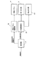
図9は、実施の形態1に係る液晶表示装置1の制御系の構成を概略的に示すブロック図である。図9に示されるように、液晶表示装置1は、液晶パネル11、液晶パネル駆動部22、第2の光源18、第1の光源101、光源駆動部23及び制御部21を有している。液晶パネル駆動部22は、液晶パネル11を駆動する。液晶パネル駆動部22は、液晶パネル制御信号に基づいて液晶パネル11を駆動し、液晶パネル11に映像を表示させる。光源駆動部23は、第2の光源18及び第1の光源101を駆動する。光源駆動部23は、光源制御信号に基づいて第2の光源18及び第1の光源101を駆動して、液晶パネル11に表示される映像の輝度を調整する。制御部21は、液晶パネル駆動部22の動作及び光源駆動部23の動作を制御する。制御部21は、入力された映像信号に画像処理を施し、入力された映像信号に基づく液晶パネル制御信号及び光源制御信号を生成する。制御部21は、液晶パネル制御信号を液晶パネル駆動部22に供給し、光源制御信号を光源駆動部23に供給する。
FIG. 9 is a block diagram schematically showing the configuration of the control system of the liquid crystal display device 1 according to the first embodiment. As illustrated in FIG. 9, the liquid crystal display device 1 includes a liquid crystal panel 11, a liquid crystal panel driving unit 22, a second light source 18, a first light source 101, a light source driving unit 23, and a control unit 21. The liquid crystal panel drive unit 22 drives the liquid crystal panel 11. The liquid crystal panel driving unit 22 drives the liquid crystal panel 11 based on the liquid crystal panel control signal, and causes the liquid crystal panel 11 to display an image. The light source driving unit 23 drives the second light source 18 and the first light source 101. The light source driving unit 23 drives the second light source 18 and the first light source 101 based on the light source control signal, and adjusts the luminance of the image displayed on the liquid crystal panel 11. The control unit 21 controls the operation of the liquid crystal panel driving unit 22 and the operation of the light source driving unit 23. The control unit 21 performs image processing on the input video signal, and generates a liquid crystal panel control signal and a light source control signal based on the input video signal. The control unit 21 supplies a liquid crystal panel control signal to the liquid crystal panel drive unit 22 and supplies a light source control signal to the light source drive unit 23.
液晶パネル駆動部22は、制御部21から受け取った液晶パネル制御信号に基づいて、液晶パネル11の液晶層の光透過率を画素単位で変化させる。液晶パネル11の各画素は、例えば、赤色(R)、緑色(G)、青色(B)の3つの副画素(第1から第3の副画素)から構成されている。第1の副画素は、赤色の光のみを透過するカラーフィルタを有し、第2の副画素は、緑色の光のみを透過するカラーフィルタを有し、第3の副画素は、青色の光のみを透過するカラーフィルタを有している。
The liquid crystal panel driving unit 22 changes the light transmittance of the liquid crystal layer of the liquid crystal panel 11 in units of pixels based on the liquid crystal panel control signal received from the control unit 21. Each pixel of the liquid crystal panel 11 is composed of, for example, three sub-pixels (first to third sub-pixels) of red (R), green (G), and blue (B). The first subpixel includes a color filter that transmits only red light, the second subpixel includes a color filter that transmits only green light, and the third subpixel includes blue light. A color filter that only transmits light.
制御部21は、液晶パネル駆動部22に、液晶パネル11の各副画素の光透過率を制御させることで、液晶パネル11にカラー画像を表示させる。言い換えれば、液晶パネル11は、面発光導光板15から入射した照明光L14を空間的に変調することで画像光を作り出して、画像光を表示面11aから出射する。ここで、画像光とは、画像情報を有する光のことである。
The control unit 21 causes the liquid crystal panel driving unit 22 to display the color image on the liquid crystal panel 11 by controlling the light transmittance of each sub-pixel of the liquid crystal panel 11. In other words, the liquid crystal panel 11 spatially modulates the illumination light L14 incident from the surface light-emitting light guide plate 15 to create image light and emit the image light from the display surface 11a. Here, the image light is light having image information.
面発光導光板15は、角度強度分布の異なる光線L11,L12を入射し、表面15aから出射する。この場合、第2の光線L11及び第1の光線L12の角度強度分布の違いは、面内輝度分布の輝度むらの原因となる。また、第2の光源18及び第1の光源101が、それぞれ異なる色の光を発することから、この場合、面内輝度分布の輝度むらは、色むらとなって表示面11aに現れてしまう。
The surface emitting light guide plate 15 receives light rays L11 and L12 having different angular intensity distributions and emits the light from the surface 15a. In this case, the difference in angular intensity distribution between the second light ray L11 and the first light ray L12 causes uneven brightness in the in-plane luminance distribution. Further, since the second light source 18 and the first light source 101 emit light of different colors, in this case, the luminance unevenness of the in-plane luminance distribution appears as color unevenness on the display surface 11a.
しかし、実施の形態1に係る面発光導光板15は、シリンドリカルミラー102と角度強度分布整形領域15eとを用いて、レーザ発光素子から出射する第1の光線L12の非常に狭い角度強度分布を、LED素子から出射する第2の光線L11の角度強度分布と略等しくなるように整形する。これにより、面発光導光板15は、表示面11aにおける色むらの発生を抑制している。
However, the surface-emitting light guide plate 15 according to the first embodiment uses the cylindrical mirror 102 and the angular intensity distribution shaping region 15e to obtain a very narrow angular intensity distribution of the first light beam L12 emitted from the laser light emitting element. The second light beam L11 emitted from the LED element is shaped so as to be substantially equal to the angular intensity distribution. Thereby, the surface emitting light guide plate 15 suppresses the occurrence of color unevenness on the display surface 11a.
青緑色の第2の光線L11及び赤色の第1の光線L12は、面発光導光板15の光入射面15cに入射する。光線L11,L12は、面発光導光板15の光入射面15c近傍に設けられた角度強度分布整形領域15eを伝播することにより混ざり合って白色の混合光線L13となる。その後、混合光線L13は、微小光学素子16により液晶パネル11に向けて面発光導光板15から出射する。
The blue-green second light beam L11 and the red first light beam L12 are incident on the light incident surface 15c of the surface light-emitting light guide plate 15. The light beams L11 and L12 are mixed by being propagated through the angular intensity distribution shaping region 15e provided in the vicinity of the light incident surface 15c of the surface light-emitting light guide plate 15 to become a white mixed light beam L13. Thereafter, the mixed light beam L <b> 13 is emitted from the surface light-emitting light guide plate 15 toward the liquid crystal panel 11 by the micro optical element 16.
実施の形態1に係る面発光導光板15では、各色の光線L11,L12は、同等の角度強度分布で微小光学素子16を備えた領域15fに入射する。したがって、面発光導光板15から出射する照明光L14は、xy平面において、色むらのない白色の面状の光を出射する。なお、制御部21が光源駆動部23を制御して、第2の光線L11の輝度と第1の光線L12の輝度との割合を調整することができる。
In the surface-emitting light guide plate 15 according to the first embodiment, the light beams L11 and L12 of each color are incident on the region 15f provided with the micro optical element 16 with an equivalent angular intensity distribution. Accordingly, the illumination light L14 emitted from the surface light-emitting light guide plate 15 emits white planar light having no color unevenness in the xy plane. In addition, the control part 21 can control the light source drive part 23, and can adjust the ratio of the brightness | luminance of the 2nd light ray L11, and the brightness | luminance of the 1st light ray L12.
液晶表示装置1は、表示色の色純度を高めることで、色再現範囲を広げることができる。この場合、液晶表示装置1は、液晶パネル11のカラーフィルタの透過波長帯域の幅を狭く設定しなければならない。しかし、透過波長帯域の幅を狭く設定すると、カラーフィルタを透過する光の透過光量は、減少する。このため、表示色の色純度を高めようとする場合、カラーフィルタを透過する光の透過光量の減少によって輝度が落ちるという問題が発生する。さらに、従来使用されていた蛍光ランプは、赤色領域の発光スペクトルのピークがオレンジ色の波長領域にある。同様に、黄色蛍光体を利用した白色のLEDも、赤色領域の発光スペクトルのピークがオレンジ色の波長領域にある。すなわち、赤色領域の波長のピークは、赤色領域からずれたオレンジ色の領域にある。特に、赤色において色純度を高めようとすると、極めて透過光量が落ち、著しく輝度が低下してしまう。
The liquid crystal display device 1 can widen the color reproduction range by increasing the color purity of the display color. In this case, the liquid crystal display device 1 must set the width of the transmission wavelength band of the color filter of the liquid crystal panel 11 to be narrow. However, when the width of the transmission wavelength band is set narrow, the amount of light transmitted through the color filter decreases. For this reason, when the color purity of the display color is to be increased, there arises a problem that the luminance is lowered due to a decrease in the amount of light transmitted through the color filter. In addition, fluorescent lamps that have been used conventionally have an emission spectrum peak in the red region in the orange wavelength region. Similarly, a white LED using a yellow phosphor also has an emission spectrum peak in the red region in the orange wavelength region. That is, the wavelength peak in the red region is in an orange region that is shifted from the red region. In particular, if the color purity is to be increased in red, the amount of transmitted light is extremely reduced and the luminance is significantly reduced.
実施の形態1に係る液晶表示装置1においては、第2の光源18は、青緑色の第2の光線L11を出射するLED素子を有している。青緑色の第2の光線L11は、青色と緑色の光とを混ぜている。また、第1の光源101は、赤色の第1の光線L12を出射する単色のレーザ発光素子を有している。第1の光線L12のスペクトルは、例えば、640nm付近にピークを有する。また、第1の光線L12の波長幅は、半値全幅で1nmと非常に狭く、色純度が高い。このように、第1の光源101が、赤色のレーザ発光素子を用いることにより、赤色の色純度を向上させることができる。すなわち、液晶表示装置1は、表示色の色再現範囲を広げることができる。
In the liquid crystal display device 1 according to the first embodiment, the second light source 18 has an LED element that emits a blue-green second light beam L11. The blue-green second light beam L11 mixes blue and green light. The first light source 101 includes a monochromatic laser light emitting element that emits the first red light beam L12. The spectrum of the first light ray L12 has a peak in the vicinity of 640 nm, for example. The wavelength width of the first light beam L12 is as narrow as 1 nm in full width at half maximum, and the color purity is high. In this manner, the first light source 101 can improve the color purity of red by using a red laser light emitting element. That is, the liquid crystal display device 1 can widen the color reproduction range of display colors.
なお、実施の形態1においては、第1の光源101が640nm付近にピークを有するレーザ発光素子を有する場合を説明したが、本発明は、これに限定されない。第1の光源101が、より短波長側の赤色レーザ発光素子を使用することにより、波長に対する視感度が上がるため、輝度/投入電力の比を向上することが可能となり、より消費電力低減効果が得られる。また、より長波長側の赤色レーザ発光素子を使用することにより、色再現範囲を広げ色鮮やかな画像を提供することが可能となる。
In the first embodiment, the case where the first light source 101 has a laser light emitting element having a peak near 640 nm has been described, but the present invention is not limited to this. Since the first light source 101 uses a red laser light emitting element on the shorter wavelength side, the visibility with respect to the wavelength is increased, so that the ratio of luminance / input power can be improved, and the power consumption can be further reduced. can get. Further, by using a longer wavelength red laser light emitting element, it is possible to widen the color reproduction range and provide a vivid image.
スペクトル幅が非常に狭く色純度を向上させることが可能なレーザ発光素子は、非常に狭い角度強度分布を有する。このレーザ発光素子と広い角度強度分布を有するLED素子とから白色の面光源を生成する面光源装置においては、レーザ光の狭い角度強度分布のため、色むらが問題となる。
The laser light-emitting element that has a very narrow spectrum width and can improve color purity has a very narrow angular intensity distribution. In the surface light source device that generates a white surface light source from the laser light emitting element and the LED element having a wide angular intensity distribution, color unevenness becomes a problem due to the narrow angular intensity distribution of the laser light.
しかし、実施の形態1における液晶表示装置1の面光源装置100は、レーザ第1の光源101から出射した第1の光線L12がシリンドリカルミラー102及び角度強度分布整形領域15eを介すことにより、第1の光線L12の角度強度分布がLED素子から出射する第2の光線L11の角度強度分布と同等の形状に整形される。このため、面光源装置100は、色むらの無い白色の面状の光を得ることができる。
However, in the surface light source device 100 of the liquid crystal display device 1 according to the first embodiment, the first light beam L12 emitted from the laser first light source 101 passes through the cylindrical mirror 102 and the angular intensity distribution shaping region 15e. The angular intensity distribution of the first light beam L12 is shaped into the same shape as the angular intensity distribution of the second light beam L11 emitted from the LED element. For this reason, the surface light source device 100 can obtain white planar light having no color unevenness.
なお、照明光L14は、第1の光学シート12及び第2光学シート13などで反射して-z軸方向に進行する場合がある。照明光L14は、面発光導光板15から液晶パネル11に向けて出射した光である。高輝度化及び低消費電力化を実現するためには、それらの反射光を再び液晶パネル11の照明光として利用する必要がある。実施の形態1に係る液晶表示装置1は、面発光導光板15の-z軸方向側に光反射シート17を備えている。光反射シート17は、-z軸方向に進む光を+z軸方向に向ける。これにより、液晶表示装置1は、効率的に光を利用することができる。
Note that the illumination light L14 may be reflected by the first optical sheet 12 and the second optical sheet 13 and travel in the −z-axis direction. The illumination light L14 is light emitted from the surface emitting light guide plate 15 toward the liquid crystal panel 11. In order to realize high luminance and low power consumption, it is necessary to use the reflected light as illumination light for the liquid crystal panel 11 again. The liquid crystal display device 1 according to Embodiment 1 includes a light reflecting sheet 17 on the −z-axis direction side of the surface emitting light guide plate 15. The light reflecting sheet 17 directs light traveling in the −z axis direction in the + z axis direction. Thereby, the liquid crystal display device 1 can use light efficiently.
以上に説明したように、実施の形態1に係る面光源装置100は、面発光導光板15、第2の光源18、第1の光源101及びシリンドリカルミラー102を備えている。第2の光源18は、面発光導光板15の光入射面(側面)15cに対向する位置に配置されている。第1の光源101は、面発光導光板15の光入射面15cより背面15b側の位置に配置されている。シリンドリカルミラー102は、第1の光線L12を光入射面15cに導く光路変更部材としての機能を有している。このように、実施の形態1に係る面光源装置100は、シリンドリカルミラー102を用いて第1の光線L12の進行方向を面発光導光板15の光入射面15cの方向に変えている。このため、面発光導光板15の厚み方向に並ぶ2種類の光源を面発光導光板15の光入射面15cに対向して配置させた従来の構成と比べて、面発光導光板15の厚みを薄くすることができる。
As described above, the surface light source device 100 according to Embodiment 1 includes the surface emitting light guide plate 15, the second light source 18, the first light source 101, and the cylindrical mirror 102. The second light source 18 is disposed at a position facing the light incident surface (side surface) 15 c of the surface emitting light guide plate 15. The first light source 101 is disposed at a position closer to the back surface 15b than the light incident surface 15c of the surface light-emitting light guide plate 15. The cylindrical mirror 102 has a function as an optical path changing member that guides the first light beam L12 to the light incident surface 15c. As described above, the surface light source device 100 according to Embodiment 1 uses the cylindrical mirror 102 to change the traveling direction of the first light beam L12 to the direction of the light incident surface 15c of the surface light-emitting light guide plate 15. For this reason, the thickness of the surface light-emitting light guide plate 15 is smaller than that of the conventional configuration in which two types of light sources arranged in the thickness direction of the surface light-emitting light guide plate 15 are arranged to face the light incident surface 15 c of the surface light-emitting light guide plate 15. Can be thinned.
また、実施の形態1に係る面光源装置100は、シリンドリカルミラー102及び角度強度分布整形領域15eを備えている。そして、シリンドリカルミラー102は、第1の光線L12の進行方向及び角度強度分布を変える光路変更部材としての機能を有している。このため、面光源装置100は、領域15fに入射する直前の第1の光線L12の角度強度分布を、領域15fに入射する直前の第2の光線L11の角度強度分布に近付けることができる。領域15fは、面発光導光板15の背面15b側に微小光学素子16を備えている。
Further, the surface light source device 100 according to the first embodiment includes a cylindrical mirror 102 and an angular intensity distribution shaping region 15e. The cylindrical mirror 102 functions as an optical path changing member that changes the traveling direction and angular intensity distribution of the first light beam L12. Therefore, the surface light source device 100 can bring the angular intensity distribution of the first light beam L12 immediately before entering the region 15f closer to the angular intensity distribution of the second light beam L11 immediately before entering the region 15f. The region 15 f includes the micro optical element 16 on the back surface 15 b side of the surface light-emitting light guide plate 15.
このように、面光源装置100は、シリンドリカルミラー102及び角度強度分布整形領域15eを用いて、第1の光線L12の角度強度分布を第2の光線L11の角度強度分布に近付けている。これにより、第2の光線L11が作り出す照明光L14の面内輝度分布と、第1の光線L12が作り出す照明光L14の面内輝度分布との差が抑制される。そして、面光源装置100は、照明光L14の色むらを低減することができる。照明光L14は、面発光導光板15の表面15aから出射する面状の光である。また、照明光L14は、第2の光線L11と第1の光線L12とを足し合わせた白色の光である。
As described above, the surface light source device 100 uses the cylindrical mirror 102 and the angular intensity distribution shaping region 15e to bring the angular intensity distribution of the first light beam L12 closer to the angular intensity distribution of the second light beam L11. Thereby, the difference between the in-plane luminance distribution of the illumination light L14 generated by the second light beam L11 and the in-plane luminance distribution of the illumination light L14 generated by the first light beam L12 is suppressed. And the surface light source device 100 can reduce the color nonuniformity of the illumination light L14. The illumination light L14 is planar light emitted from the surface 15a of the surface emitting light guide plate 15. The illumination light L14 is white light obtained by adding the second light beam L11 and the first light beam L12.
また、実施の形態1に係る面光源装置100を有する液晶表示装置1は、面発光導光板15の厚みが薄くなるので、薄型化を実現できる。また、液晶表示装置1は、面光源装置100の色むらを低減することができるので、液晶パネル11の表示面11aの色むらを低減し画質の向上を実現できる。
Further, in the liquid crystal display device 1 having the surface light source device 100 according to the first embodiment, the thickness of the surface light-emitting light guide plate 15 is reduced, so that the thickness can be reduced. Further, since the liquid crystal display device 1 can reduce the color unevenness of the surface light source device 100, the color unevenness of the display surface 11a of the liquid crystal panel 11 can be reduced and the image quality can be improved.
実施の形態1に係る面光源装置100によれば、制御部21は、光源駆動部23に、第1の光線L12の輝度及び第2の光線L11の輝度を調整させる。制御部21は、映像信号に基づいて各光源L11,L12の発光量を調整する。これにより、液晶表示装置1は、消費電力を低減できる。
According to the surface light source device 100 according to Embodiment 1, the control unit 21 causes the light source driving unit 23 to adjust the luminance of the first light beam L12 and the luminance of the second light beam L11. The control unit 21 adjusts the light emission amounts of the light sources L11 and L12 based on the video signal. Thereby, the liquid crystal display device 1 can reduce power consumption.
また、液晶表示装置1は、光源に少なくとも1種類のレーザ発光素子を採用している。このことにより、液晶表示装置1は、色再現領域を広げ色鮮やかでかつ色むらの無い画像を提供することが可能となる。
Further, the liquid crystal display device 1 employs at least one type of laser light emitting element as a light source. As a result, the liquid crystal display device 1 can widen the color reproduction area and provide an image that is vivid and has no color unevenness.
さらに、面光源装置100は、第2の光源18を面発光導光板15の側面(光入射面15c)に配置し、第1の光源101を面発光導光板15の背面15b側に配置している。このように光源18,101を離して配置することで、面光源装置100は、それぞれの光源18,101が発する熱による局所的な温度上昇を緩和できる。これにより、面光源装置100は、周囲温度の上昇による光源18,101の発光効率の低下を抑制できる。
Furthermore, the surface light source device 100 has the second light source 18 disposed on the side surface (light incident surface 15 c) of the surface light-emitting light guide plate 15, and the first light source 101 is disposed on the back surface 15 b side of the surface light-emitting light guide plate 15. Yes. By disposing the light sources 18 and 101 in this way, the surface light source device 100 can alleviate a local temperature increase due to the heat generated by the light sources 18 and 101. Thereby, the surface light source device 100 can suppress the fall of the light emission efficiency of the light sources 18 and 101 by the raise of ambient temperature.
上記の説明では、実施の形態1に係る面発光装置100は、光線L11,L12が面発光導光板15の短辺の側面(光入射面15c)から入射する構成を採用している。しかし、面発光装置100は、面発光導光板15の長辺の側面を光入射面とすることも可能である。これは、光源18,101の配列、シリンドリカルミラー102の位置、微小光学素子16の配列及び微小光学素子16の形状などを適切に変更することによって可能となる。
In the above description, the surface light emitting device 100 according to Embodiment 1 employs a configuration in which the light beams L11 and L12 are incident from the side surface (light incident surface 15c) of the short side of the surface light emitting light guide plate 15. However, the surface light-emitting device 100 can also use the long side surface of the surface light-emitting light guide plate 15 as a light incident surface. This can be achieved by appropriately changing the arrangement of the light sources 18 and 101, the position of the cylindrical mirror 102, the arrangement of the micro optical elements 16, the shape of the micro optical elements 16, and the like.
また、上記の説明では、実施の形態1に係る面発光装置100は、光線L11,L12が面発光導光板15の1つの側面(光入射面15c)から入射する構成を採用している。しかし、面発光装置100は、面発光導光板15の対向する2つの側面(例えば、光入射面15cとそれに対向する面15d)を光入射面とすることも可能である。これは、光源18,101の配列、シリンドリカルミラー102の位置、微小光学素子16の配列及び微小光学素子16の形状などを適切に変更することによって可能となる。
In the above description, the surface light emitting device 100 according to Embodiment 1 employs a configuration in which the light beams L11 and L12 are incident from one side surface (light incident surface 15c) of the surface light emitting light guide plate 15. However, in the surface light emitting device 100, the two side surfaces (for example, the light incident surface 15c and the surface 15d facing it) facing the surface emitting light guide plate 15 can be used as the light incident surface. This can be achieved by appropriately changing the arrangement of the light sources 18 and 101, the position of the cylindrical mirror 102, the arrangement of the micro optical elements 16, the shape of the micro optical elements 16, and the like.
また、実施の形態1に係る面発光装置100の光源駆動部23は、画像信号に基づいて第2の光源18の出力及び第1の光源101の出力を個別に制御している。このため、面発光装置100は、消費電力を低減できる。また、面発光装置100は、迷光を低減してコントラストを向上させることができる。なぜなら、余分な光を低減することで、迷光を低減することができるからである。なお、迷光とは、光学機器内で、正規の光路以外をたどる光のことで、希望する用途に有害な光である。
Further, the light source driving unit 23 of the surface light emitting device 100 according to Embodiment 1 individually controls the output of the second light source 18 and the output of the first light source 101 based on the image signal. For this reason, the surface light-emitting device 100 can reduce power consumption. Further, the surface light emitting device 100 can improve the contrast by reducing stray light. This is because stray light can be reduced by reducing excess light. Note that stray light is light that travels outside the regular optical path in an optical device, and is harmful to a desired application.
実施の形態1に係る液晶表示装置1は、第2の光源18に青緑色のLED素子を採用し、第1の光源101に赤色のレーザ発光素子を採用する構成とした。しかし、本発明は、これに限るものではない。例えば、複数の異なる光源を備える液晶表示装置において、広い角度強度分布を有する光源と狭い角度強度分布とを有する光源とを備える場合に、本発明を適用できる。
The liquid crystal display device 1 according to Embodiment 1 has a configuration in which a blue-green LED element is employed as the second light source 18 and a red laser light-emitting element is employed as the first light source 101. However, the present invention is not limited to this. For example, the present invention can be applied to a liquid crystal display device that includes a plurality of different light sources and includes a light source having a wide angular intensity distribution and a light source having a narrow angular intensity distribution.
例えば、第2の光源18に青緑色の光を放射する蛍光ランプを採用し、第1の光源101に赤色のレーザ発光素子を採用する構成でも本発明を適用できる。この場合、蛍光ランプとレーザ発光素子とにより白色の光を生成することができる。また、第2の光源18に青色のLED素子と赤色のLED素子とを採用し、第1の光源101に緑色のレーザ発光素子を採用する構成でも本発明を適用できる。この場合、LED素子とレーザ発光素子とにより白色の光を生成することができる。さらに、第2の光源18に緑色のLED素子を採用し、第1の光源101に青色のレーザ発光素子と赤色のレーザ発光素子とを採用することもできる。
For example, the present invention can be applied to a configuration in which a fluorescent lamp that emits blue-green light is used for the second light source 18 and a red laser light emitting element is used for the first light source 101. In this case, white light can be generated by the fluorescent lamp and the laser light emitting element. The present invention can also be applied to a configuration in which a blue LED element and a red LED element are employed for the second light source 18 and a green laser light emitting element is employed for the first light source 101. In this case, white light can be generated by the LED element and the laser light emitting element. Further, a green LED element may be employed for the second light source 18, and a blue laser light emitting element and a red laser light emitting element may be employed for the first light source 101.
また、実施の形態1に係る面光源装置100は、シリンドリカルミラー102を光路変更部材として採用した。しかし、本発明は、これに限るものではない。光路変更部材は、次の2つの機能を有すれば他の素子を採用してもよい。第1の機能は、第1の光線L12の軸を面発光導光板15の基準平面に対して任意の角度に傾ける機能である。第2の機能は、第1の光線L12の角度強度分布を任意の角度に広げる機能である。
Further, the surface light source device 100 according to Embodiment 1 employs the cylindrical mirror 102 as the optical path changing member. However, the present invention is not limited to this. The optical path changing member may employ another element as long as it has the following two functions. The first function is a function of tilting the axis of the first light beam L12 at an arbitrary angle with respect to the reference plane of the surface emitting light guide plate 15. The second function is a function of expanding the angular intensity distribution of the first light ray L12 to an arbitrary angle.
例えば、光路変更部材は、凸面形状のシリンドリカルミラーを採用することができる。また、光路変更部材は、断面が多角形状の光反射ミラーを採用することができる。また、光路変更部材は、表面にランダムな凹凸形状を有する反射膜を有した部材を採用することができる。
For example, a convex cylindrical mirror can be adopted as the optical path changing member. The light path changing member can employ a light reflecting mirror having a polygonal cross section. Further, as the optical path changing member, a member having a reflective film having a random uneven shape on the surface can be adopted.
なお、第1の機能及び第2の機能は、第1の光線L12が角度強度分布整形領域15eを伝播した後に、第1の光線L12の角度強度分布が第2の光線L11の角度強度分布と近似するために必要な機能である。つまり、任意の角度強度分布形状とは、第1の光線L12が、角度強度分布整形領域15eを通った後に、第2の光線L11の角度強度分布と近似するために必要な、光路変更部材を出射した後の第1の光線L12の角度強度分布形状である。また、任意の傾き角とは、第1の光線L12が、角度強度分布整形領域15eを通った後に、第2の光線L11の角度強度分布と近似するために必要な、光路変更部材を出射した後の第1の光線202の傾き角である。
The first function and the second function are such that after the first light ray L12 propagates through the angular intensity distribution shaping region 15e, the angular intensity distribution of the first light ray L12 becomes the angular intensity distribution of the second light ray L11. This function is necessary for approximation. In other words, an arbitrary angular intensity distribution shape means an optical path changing member necessary for approximating the angular intensity distribution of the second light ray L11 after the first light ray L12 passes through the angular intensity distribution shaping region 15e. It is the angular intensity distribution shape of the first light beam L12 after being emitted. In addition, the arbitrary inclination angle means that the first light beam L12 passes through the angular intensity distribution shaping region 15e and then exits the optical path changing member necessary to approximate the angular intensity distribution of the second light beam L11. This is the inclination angle of the later first light ray 202.
また、上記の説明では、面光源装置100を液晶表示装置1のバックライトユニットとして用いた場合について説明したが、面光源装置を照明用などの他の用途に用いてもよい。
In the above description, the case where the surface light source device 100 is used as the backlight unit of the liquid crystal display device 1 has been described. However, the surface light source device may be used for other purposes such as illumination.
実施の形態2.
図10は、実施の形態2に係る液晶表示装置2(面光源装置200を含む)の一例の構成を概略的に示す断面図である。また、図11は、実施の形態2に係る液晶表示装置3(面光源装置300を含む)の他の例の構成を概略的に示す断面図である。図10及び図11において、図1(実施の形態1)で示された構成要素と同一又は対応する構成要素には、同じの符号を付す。実施の形態2に係る面光源装置200及び300は、光源用導光部材210を備える点において、実施の形態1に係る面光源装置100と異なる。
Embodiment 2. FIG.
FIG. 10 is a cross-sectional view schematically showing a configuration of an example of the liquid crystal display device 2 (including the surface light source device 200) according to the second embodiment. FIG. 11 is a cross-sectional view schematically showing a configuration of another example of the liquid crystal display device 3 (including the surface light source device 300) according to the second embodiment. 10 and 11, the same reference numerals are given to the same or corresponding components as those shown in FIG. 1 (Embodiment 1). The surface light source devices 200 and 300 according to the second embodiment are different from the surface light source device 100 according to the first embodiment in that a light source light guide member 210 is provided.
図10に示されるように、実施の形態2に係る液晶表示装置2及び3は、液晶パネル11、第1の光学シート12、第2の光学シート13、面発光導光板15、光反射シート17、第2の光源8、第1の光源201、光源用導光部材210、及びシリンドリカルミラー202を有している。面発光導光板15は、実施の形態1と同様に、背面15bに微小光学素子16を有している。これらの構成要素11,12,13,15,17,210は、液晶表示装置2及び3の厚み方向(z軸方向)に順に配列している。
As shown in FIG. 10, the liquid crystal display devices 2 and 3 according to the second embodiment include a liquid crystal panel 11, a first optical sheet 12, a second optical sheet 13, a surface light-emitting light guide plate 15, and a light reflecting sheet 17. , Second light source 8, first light source 201, light source light guide member 210, and cylindrical mirror 202. The surface light-emitting light guide plate 15 has the micro optical element 16 on the back surface 15b as in the first embodiment. These constituent elements 11, 12, 13, 15, 17, and 210 are sequentially arranged in the thickness direction (z-axis direction) of the liquid crystal display devices 2 and 3.
第2の光源18は、実施の形態1における第2の光源18と同様に、面発光導光板15の光入射面(側面)15cのz軸方向の長さ(すなわち、面発光導光板15の厚み)の範囲内に配置されている。第2の光源18から出射した第2の光線L21は、広い角度強度分布を有している。実施の形態2の第2の光源18から出射する第2の光線L21の角度強度分布は、全角が120度の略ランバート分布である。第2の光源18から出射した第2の光線L21は、面発光導光板15の光入射面15cに向けて(略+x軸方向に)進行し、光入射面15cから面発光導光板15に入射する。第2の光源18は、例えば、複数のLED素子を直線上に等間隔で並べた光源装置である。ただし、第2の光源18の構成は、直線上や等間隔などの構成に限定されず、他の構成をとることもできる。
Similarly to the second light source 18 in the first embodiment, the second light source 18 is the length of the light incident surface (side surface) 15c of the surface light-emitting light guide plate 15 in the z-axis direction (that is, the surface light-emitting light guide plate 15 (Thickness). The second light beam L21 emitted from the second light source 18 has a wide angular intensity distribution. The angular intensity distribution of the second light beam L21 emitted from the second light source 18 of the second embodiment is a substantially Lambertian distribution with a full angle of 120 degrees. The second light beam L21 emitted from the second light source 18 travels (approximately in the + x axis direction) toward the light incident surface 15c of the surface light-emitting light guide plate 15, and enters the surface light-emitting light guide plate 15 from the light incident surface 15c. To do. The second light source 18 is, for example, a light source device in which a plurality of LED elements are arranged on a straight line at equal intervals. However, the configuration of the second light source 18 is not limited to a configuration such as a straight line or an equal interval, and other configurations may be employed.
第1の光源201から出射する第1の光線L22は、第2の光線L21に対し狭い角度強度分布を有する。実施の形態2の第1の光源201から出射する第1の光線L22の角度強度分布は、全角が略6度の略ガウシアン分布である。第1の光源201は、実施の形態1における第1の光源101と同様に、複数のレーザ発光素子を直線上に等間隔で並べた光源装置である。ただし、第1の光源201の構成は、直線上や等間隔などの構成に限定されず、他の構成をとることもできる。第1の光源201は、光反射シート17の背面15b側(-z軸方向)に配置されている。また、第1の光源201は、光源用導光部材210の光入射面210aに対向して配置されている。
The first light beam L22 emitted from the first light source 201 has a narrow angular intensity distribution with respect to the second light beam L21. The angular intensity distribution of the first light ray L22 emitted from the first light source 201 of the second embodiment is a substantially Gaussian distribution with a full angle of approximately 6 degrees. Similar to the first light source 101 in the first embodiment, the first light source 201 is a light source device in which a plurality of laser light emitting elements are arranged on a straight line at equal intervals. However, the configuration of the first light source 201 is not limited to a configuration such as a straight line or an equal interval, and other configurations can be adopted. The first light source 201 is disposed on the back surface 15b side (−z-axis direction) of the light reflecting sheet 17. The first light source 201 is disposed so as to face the light incident surface 210a of the light guide member 210 for light source.
光源用導光部材210は、xy平面に平行に配置された直方体の板状部211と、xy平面に対して約45度の傾斜を持った傾斜面210bを有する光折返し部212とから構成されている。傾斜面210bは、y軸を通りx-y平面に対して略45度の傾斜を持つ平面に対して平行である。傾斜面210bは、y軸を通りxy平面に対して略45度の傾斜を持つ平面に対して平行である。光源用導光部材210は、例えば、厚み1mmの板状の部材である。光源用導光部材210は、例えば、PMMAなどのアクリル樹脂からなる透明材料で作製されている。
The light source light guide member 210 includes a rectangular parallelepiped plate-like portion 211 arranged in parallel to the xy plane, and a light return portion 212 having an inclined surface 210b having an inclination of about 45 degrees with respect to the xy plane. ing. The inclined surface 210b is parallel to a plane that passes through the y axis and has an inclination of approximately 45 degrees with respect to the xy plane. The inclined surface 210b is parallel to a plane that passes through the y axis and has an inclination of about 45 degrees with respect to the xy plane. The light source light guide member 210 is, for example, a plate-like member having a thickness of 1 mm. The light source light guide member 210 is made of a transparent material made of an acrylic resin such as PMMA, for example.
第1の光源から出射される第1の光線L22は、全角が略6度の角度強度分布を有する。第1の光線L22は、光源用導光部材210に入射することにより全角が略5度の角度強度分布の光となる。第1の光線L22の全てが、光源用導光部材210の傾斜面210bで全反射するように、傾斜面210bに対する第1の光線L22の入射角を調整する。これにより、光源用導光部材201における光損失は、抑制される。
The first light beam L22 emitted from the first light source has an angular intensity distribution with a full angle of approximately 6 degrees. The first light beam L22 enters the light guide member 210 for light source, and becomes light having an angular intensity distribution with a full angle of approximately 5 degrees. The incident angle of the first light beam L22 with respect to the inclined surface 210b is adjusted so that all of the first light rays L22 are totally reflected by the inclined surface 210b of the light guide member 210 for light source. Thereby, the optical loss in the light guide member 201 for light sources is suppressed.
例えば、屈折率1.49のアクリル樹脂部材から屈折率1.00の空気層に光線が入射する場合には、全反射条件を満足する臨界角θtは、スネルの法則から、次に示す数式(1)で表される。
θt=sin-1(1.00/1.49)≒42.16° ・・・(1)
For example, when a light ray is incident on an air layer having a refractive index of 1.00 from an acrylic resin member having a refractive index of 1.49, the critical angle θt that satisfies the total reflection condition is calculated from the following formula (Snell's law: 1).
θt = sin −1 (1.00 / 1.49) ≈42.16 ° (1)
第1の光線L22の角度強度分布の全角が5度(半角は、2.5度)の場合、傾斜面210bに対する第1の光線L22の入射角は、(θt+2.5)度以上が望ましい。臨界角θtが約42.16度となるため、傾斜面210bに対する第1の光線L22の入射角は、44.7度以上が望ましい。
When the full angle of the angular intensity distribution of the first light beam L22 is 5 degrees (half angle is 2.5 degrees), the incident angle of the first light beam L22 with respect to the inclined surface 210b is desirably (θt + 2.5) degrees or more. Since the critical angle θt is about 42.16 degrees, the incident angle of the first light ray L22 with respect to the inclined surface 210b is desirably 44.7 degrees or more.
図10に示されるように、光源用導光部材210は、光入射面210a、傾斜面210b及び光出射面210cを有している。光出射面210cは、シリンドリカルミラー202の光反射面202aに対向している。傾斜面210bは、xy平面に対して略45度の角度で傾斜している。傾斜面210bは、第1の光線L22の進行方向を-x軸方向から略+z軸方向に変更する。すなわち、第1の光線L22は、傾斜面210bで反射し、進行方向を略+z軸方向に変える。第1の光線L22の屈折は、光源用導光部材210と空気層との界面における屈折率差により生じる。
As shown in FIG. 10, the light guide member 210 for light source has a light incident surface 210a, an inclined surface 210b, and a light emitting surface 210c. The light emitting surface 210 c faces the light reflecting surface 202 a of the cylindrical mirror 202. The inclined surface 210b is inclined at an angle of approximately 45 degrees with respect to the xy plane. The inclined surface 210b changes the traveling direction of the first light ray L22 from the −x-axis direction to the approximately + z-axis direction. That is, the first light ray L22 is reflected by the inclined surface 210b and changes the traveling direction to the substantially + z-axis direction. The refraction of the first light beam L22 is caused by the difference in refractive index at the interface between the light guide member 210 for light source and the air layer.
第1の光線L22は、第1の光源201から出射する。第1の光線L22は、光源用導光部材210の光入射面210aから光源用導光部材210に入射する。第1の光線L22は、光源用導光部材210と空気層との界面で全反射して、光源用導光部材210内を-x軸方向に進行する。第1の光線L22は、傾斜面210bに達し、傾斜面210bで反射して略+z軸方向に進行方向を変える。進行方向を変えた第1の光線L22は、光出射面210cから出射した後に、シリンドリカルミラー202で反射して光入射面15cから面発光導光板15に入射する。シリンドリカルミラー202は、光路変更部材としての機能を有する。
The first light beam L22 is emitted from the first light source 201. The first light beam L <b> 22 enters the light source light guide member 210 from the light incident surface 210 a of the light source light guide member 210. The first light ray L22 is totally reflected at the interface between the light source light guide member 210 and the air layer, and travels in the light source light guide member 210 in the −x-axis direction. The first light ray L22 reaches the inclined surface 210b, is reflected by the inclined surface 210b, and changes the traveling direction in the substantially + z-axis direction. The first light beam L22 whose traveling direction has been changed is emitted from the light emitting surface 210c, then reflected by the cylindrical mirror 202, and incident on the surface emitting light guide plate 15 from the light incident surface 15c. The cylindrical mirror 202 has a function as an optical path changing member.
シリンドリカルミラー202の光反射面202aは、図1に示されるシリンドリカルミラー102の光反射面102aと同様の形状及び機能を持つ。光出射面210cから出射した第1の光線L22は、シリンドリカルミラー202の光反射面202aに向かって進む。光源用導光部材210を全反射しながら伝播する第1の光線L22の角度強度分布は、保存される。このため、光出射面210cから出射した第1の光線L22の角度強度分布は、全角が略6である。つまり、第1の光源201から出射した直後の第1の光線L22の角度強度分布と同じである。シリンドリカルミラー202に入射した第1の光線L22は、光反射面202aで反射し、進行方向を面発光導光板15の光入射面15cに向ける(略+x軸方向に向ける)。
The light reflecting surface 202a of the cylindrical mirror 202 has the same shape and function as the light reflecting surface 102a of the cylindrical mirror 102 shown in FIG. The first light beam L22 emitted from the light emitting surface 210c travels toward the light reflecting surface 202a of the cylindrical mirror 202. The angular intensity distribution of the first light ray L22 that propagates while totally reflecting the light guide member 210 for the light source is preserved. For this reason, the angular intensity distribution of the first light beam L22 emitted from the light emitting surface 210c has a full angle of approximately 6. That is, it is the same as the angular intensity distribution of the first light beam L22 immediately after being emitted from the first light source 201. The first light beam L22 incident on the cylindrical mirror 202 is reflected by the light reflecting surface 202a, and the traveling direction is directed to the light incident surface 15c of the surface emitting light guide plate 15 (substantially + x-axis direction).
第2の光源18から出射する第2の光線L21は、光入射面15cから面発光導光板15に入射する。同様に、第1の光源201から出射する第1の光線L22は、光入射面15cから面発光導光板15に入射する。第2の光線L21は、第2の光源18から略+x軸方向(図10における右方向)に、光入射面15cに向けて出射する。このとき、第2の光線21の軸は、面発光導光板15の基準平面(図10のxy平面)と略平行である。
The second light beam L21 emitted from the second light source 18 enters the surface light-emitting light guide plate 15 from the light incident surface 15c. Similarly, the first light beam L22 emitted from the first light source 201 enters the surface light-emitting light guide plate 15 from the light incident surface 15c. The second light beam L21 is emitted from the second light source 18 toward the light incident surface 15c in the approximately + x-axis direction (right direction in FIG. 10). At this time, the axis of the second light beam 21 is substantially parallel to the reference plane (xy plane in FIG. 10) of the surface light-emitting light-guiding plate 15.
第1の光線L22は、光源用導光部材210の中を伝播し、シリンドリカルミラー202の光反射面202aで反射して面発光導光板15の光入射面15cに向けて出射する。このとき、シリンドリカルミラー202は、次に示す2つの機能を有する。第1の機能は、第1の光線L22の軸を面発光導光板15の基準平面に対し任意の角度に傾ける機能である。基準平面は、図10のxy平面である。第2の機能は、第1の光線L22の角度強度分布がzx平面と平行な面で任意の形状となるように、第1の光線L12の進行方向及び角度強度分布を変える機能である。zx平面は、面発光導光板15の基準平面と直交する平面である。以下、zx平面と平行な面を面発光導光板15の厚み方向の平面と呼ぶ。ここで、光線の軸とは、光線の任意の平面における角度強度分布の加重平均となる角度方向の軸を指す。加重平均となる角度は、各角度に光の強度の重みづけをして平均することで求められる。光強度のピーク位置が角度強度分布の中心からずれている場合、光線の軸は、光強度のピーク位置の角度とはならない。光線の軸は、角度強度分布の面積の中の重心位置の角度となる。
The first light beam L22 propagates in the light guide member 210 for the light source, is reflected by the light reflecting surface 202a of the cylindrical mirror 202, and is emitted toward the light incident surface 15c of the surface emitting light guide plate 15. At this time, the cylindrical mirror 202 has the following two functions. The first function is a function of tilting the axis of the first light beam L22 at an arbitrary angle with respect to the reference plane of the surface light-emitting light guide plate 15. The reference plane is the xy plane in FIG. The second function is a function of changing the traveling direction and the angular intensity distribution of the first light beam L12 so that the angular intensity distribution of the first light beam L22 has an arbitrary shape on a plane parallel to the zx plane. The zx plane is a plane orthogonal to the reference plane of the surface emitting light guide plate 15. Hereinafter, a plane parallel to the zx plane is referred to as a plane in the thickness direction of the surface light-emitting light-guiding plate 15. Here, the axis of the light beam refers to an axis in the angular direction that is a weighted average of the angular intensity distribution in an arbitrary plane of the light beam. The angle that becomes the weighted average is obtained by weighting the light intensity to each angle and averaging the angles. When the peak position of the light intensity is deviated from the center of the angular intensity distribution, the axis of the light beam does not become the angle of the peak position of the light intensity. The ray axis is the angle of the center of gravity position in the area of the angular intensity distribution.
第1の光線L22は、角度強度分布整形領域15eにおいて、実施の形態1の第1の光線L12と同様に振舞う。第1の光線L22は、シリンドリカルミラー202で反射した後、面発光導光板15に入射する。第1の光線L22の軸は、面発光導光板15の基準平面に対し任意の角度で傾いている。第1の光線L22は、この角度を有しながら角度強度分布整形領域15eの中を+x軸方向に伝播する。
The first light beam L22 behaves in the angular intensity distribution shaping region 15e in the same manner as the first light beam L12 of the first embodiment. The first light beam L22 is reflected by the cylindrical mirror 202 and then enters the surface light-emitting light guide plate 15. The axis of the first light beam L22 is inclined at an arbitrary angle with respect to the reference plane of the surface light-emitting light guide plate 15. The first light ray L22 propagates in the + x-axis direction through the angle intensity distribution shaping region 15e while having this angle.
第1の光線L22は、角度強度分布整形領域15eの表面15aと背面15bとで反射を繰り返しながら伝播する。このとき、第1の光線L22は、自らの発散角により発散しながら伝播する。このため、第1の光線L22は、面発光導光体15の厚み方向の平面(図10のzx平面)において多重に折り畳まれる。つまり、角度強度分布整形領域15eの表面15aと背面15bとで折り返され、面発光導光板15の厚みと同等の大きさの光径に重ね合わせられる。これにより、角度強度分布整形領域15eから領域15fに出射する第1の光線L22の角度強度分布は、角度強度分布整形領域15eに入射した際の第1の光線L22の角度強度分布とこれを面発光導光板15の基準平面に対して対称に折り返した角度強度分布とを足し合わせた分布形状となる。
The first light ray L22 propagates while being repeatedly reflected by the surface 15a and the back surface 15b of the angular intensity distribution shaping region 15e. At this time, the first light beam L22 propagates while diverging at its divergence angle. For this reason, the 1st light ray L22 is folded in multiple on the plane (zx plane of FIG. 10) of the thickness direction of the surface emitting light guide 15. FIG. In other words, the angle intensity distribution shaping region 15e is folded at the front surface 15a and the back surface 15b, and is superimposed on the light diameter having the same size as the thickness of the surface light-emitting light guide plate 15. Thereby, the angular intensity distribution of the first light beam L22 emitted from the angular intensity distribution shaping region 15e to the region 15f is the same as the angular intensity distribution of the first light beam L22 when entering the angular intensity distribution shaping region 15e. A distribution shape is obtained by adding the angular intensity distributions that are folded symmetrically with respect to the reference plane of the light-emitting light guide plate 15.
第2の光源18から出射した第2の光線L21は、角度強度分布を変えることなく面発光導光板15に入射する。このため、面発光導光板15内に入射した直後の第2の光線L21は、広い角度強度分布を有する。一方、第1の光源201から出射した第1の光線L22は、第2の光線L21に対し狭い角度強度分布を有する。狭い角度強度分布の第1の光線L22が、面発光導光板15に入射すると、面発光導光板15内で2種類の光線L21,L22の角度強度分布の差が大きくなる。しかしながら、実施の形態2の面光源装置200は、シリンドリカルミラー202及び角度強度分布整形領域15eを用いて、第1の光線L22の角度強度分布を第2の光線L21の角度強度分布に略等しい形状とすることができる。
The second light beam L21 emitted from the second light source 18 enters the surface light-emitting light guide plate 15 without changing the angular intensity distribution. For this reason, the second light beam L21 immediately after entering the surface light-emitting light guide plate 15 has a wide angular intensity distribution. On the other hand, the first light beam L22 emitted from the first light source 201 has a narrow angular intensity distribution with respect to the second light beam L21. When the first light beam L22 having a narrow angular intensity distribution is incident on the surface light-emitting light guide plate 15, the difference in angular intensity distribution between the two types of light beams L21 and L22 in the surface light-emitting light guide plate 15 increases. However, the surface light source device 200 according to the second embodiment uses the cylindrical mirror 202 and the angular intensity distribution shaping region 15e, and has a shape in which the angular intensity distribution of the first light ray L22 is substantially equal to the angular intensity distribution of the second light ray L21. It can be.
第2の光源18から出射する第2の光線L21は、例えば、青緑色の光線である。第1の光源201から出射する第1の光線L22は、例えば、赤色の光線である。第2の光線L21は、光入射面15cから面発光導光板15に入射する。また、第1の光線L22は、光入射面15cから面発光導光板15に入射する。角度強度分布整形領域15eは、第2の光線21と第1の光線L22とを混合する機能も有する。2種類の光線L21,L22は、角度強度分布整形領域15eを伝播することにより混合され、混合光線L23となる。混合光線L23は、例えば、白色の光線である。なお、角度強度分布整形領域15eは、光入射面15cの近傍に配置されている。
The second light beam L21 emitted from the second light source 18 is, for example, a blue-green light beam. The first light beam L22 emitted from the first light source 201 is, for example, a red light beam. The second light ray L21 enters the surface light-emitting light guide plate 15 from the light incident surface 15c. Further, the first light ray L22 enters the surface light-emitting light guide plate 15 from the light incident surface 15c. The angular intensity distribution shaping region 15e also has a function of mixing the second light beam 21 and the first light beam L22. The two types of light beams L21 and L22 are mixed by propagating through the angular intensity distribution shaping region 15e to become a mixed light beam L23. The mixed light L23 is, for example, a white light. The angle intensity distribution shaping region 15e is disposed in the vicinity of the light incident surface 15c.
混合光線L23は、面発光導光板15の背面15bに備えられた微小光学素子16により照明光L24に変換される。照明光L24は、略+z軸方向に進行し、液晶パネル11の背面11bに向けて進む。照明光L24は、第1の光学シート13及び第1の光学シート12を透過して液晶パネル11の背面11bを照射する。第1の光学シート12は、面発光導光板15の発光面15aから出射された照明光L24を、液晶パネル11の背面11bに向ける機能を持つ。第1の光学シート13は、照明光L24による細かな照明むらなどの光学的影響を抑制する機能を持つ。
The mixed light beam L23 is converted into illumination light L24 by the micro optical element 16 provided on the back surface 15b of the surface emitting light guide plate 15. The illumination light L24 travels substantially in the + z-axis direction and travels toward the back surface 11b of the liquid crystal panel 11. The illumination light L24 passes through the first optical sheet 13 and the first optical sheet 12, and irradiates the back surface 11b of the liquid crystal panel 11. The first optical sheet 12 has a function of directing the illumination light L24 emitted from the light emitting surface 15a of the surface emitting light guide plate 15 toward the back surface 11b of the liquid crystal panel 11. The first optical sheet 13 has a function of suppressing optical influences such as fine illumination unevenness due to the illumination light L24.
光反射シート17は、面発光導光板15の背面15bに対向配置されている。混合光線L23のうちの面発光導光板15の背面15bから出射した光は、光反射シート17で反射して折り返され、面発光導光板15の背面15bに向けて進む。その後、その光は、面発光導光板15を通過して、発光面15aから液晶パネル11の背面11bに向けて照明光L24として出射される。また、混合光線L23のうち、微小光学素子16に入射した光線も、照明光L24として出射される。
The light reflecting sheet 17 is disposed to face the back surface 15b of the surface light emitting light guide plate 15. Of the mixed light beam L23, the light emitted from the back surface 15b of the surface light-emitting light guide plate 15 is reflected by the light reflecting sheet 17 and folded, and travels toward the back surface 15b of the surface light-emitting light guide plate 15. Thereafter, the light passes through the surface emitting light guide plate 15 and is emitted from the light emitting surface 15a toward the back surface 11b of the liquid crystal panel 11 as illumination light L24. Of the mixed light beam L23, the light beam incident on the micro optical element 16 is also emitted as illumination light L24.
なお、上記の説明では、光源用導光部材210の傾斜面210bは、xy平面に対して略45度の角度で傾斜しているが、本発明は、これに限られるものではない。傾斜面210bに対する第1の光線L22の入射角は、上述の臨界角θt及び第1の光線L22の角度強度分布の半角から求められる全反射の条件から設定できる。また、第1の光線L22の最適な光路を作るために、光出射面210c、シリンドリカルミラー202及び面発光導光板15などの構成要素と傾斜面210bとの位置関係によって傾斜面210bの傾斜角を変更してもよい。また、第1の光線L22の最適な光路を作るために、傾斜面210bの傾斜角に代えてシリンドリカルミラー202の配置位置及び形状を変更してもよい。
In the above description, the inclined surface 210b of the light source light guide member 210 is inclined at an angle of about 45 degrees with respect to the xy plane, but the present invention is not limited to this. The incident angle of the first light ray L22 with respect to the inclined surface 210b can be set from the total reflection condition obtained from the critical angle θt and the half angle of the angular intensity distribution of the first light ray L22. Further, in order to create an optimum optical path of the first light beam L22, the inclination angle of the inclined surface 210b is determined by the positional relationship between the components such as the light emitting surface 210c, the cylindrical mirror 202 and the surface emitting light guide plate 15 and the inclined surface 210b. It may be changed. Further, in order to create an optimum optical path of the first light beam L22, the arrangement position and shape of the cylindrical mirror 202 may be changed instead of the inclination angle of the inclined surface 210b.
傾斜面210bの傾斜角やシリンドリカルミラー202の配置位置などの調整は、次の3つの目的のために行う。第1の目的は、第1の光線L22をシリンドリカルミラー202及び面発光導光板15に効率良く入射させるためである。第1の目的は、面発光導光板15に入射した直後の第1の光線L22の軸が、面発光導光板15の基準平面に対して任意の角度で傾くことである。第3の目的は、面発光導光板15に入射した直後の第1の光線L22が、任意の角度強度分布を有することである。
The adjustment of the inclination angle of the inclined surface 210b and the arrangement position of the cylindrical mirror 202 is performed for the following three purposes. The first purpose is to make the first light beam L22 enter the cylindrical mirror 202 and the surface light-emitting light guide plate 15 efficiently. The first purpose is that the axis of the first light beam L <b> 22 immediately after entering the surface emitting light guide plate 15 is inclined at an arbitrary angle with respect to the reference plane of the surface emitting light guide plate 15. The third purpose is that the first light beam L22 immediately after entering the surface light-emitting light guide plate 15 has an arbitrary angular intensity distribution.
第1の光源201とシリンドリカルミラー202との位置関係などは、第1の光線L22の角度強度分布、第1の光線L22の光束の大きさ(直径)、シリンドリカルミラー202の曲率及び面発光導光板15の厚みなどに応じて設定される。また、シリンドリカルミラー202と面発光導光板15との位置関係などは、第1の光線L22の角度強度分布、第1の光線L22の光束の大きさ(直径)、シリンドリカルミラー202の曲率及び面発光導光板15の厚みなどに応じて設定される。したがって、各条件が異なる場合は、各部材の位置関係などを最適化する必要がある。位置関係などとは、各構成要素の配置位置及び光反射面の傾きなどで、光線の光路を決める各構成要素どうしの関係である。
The positional relationship between the first light source 201 and the cylindrical mirror 202 includes the angular intensity distribution of the first light beam L22, the size (diameter) of the light beam of the first light beam L22, the curvature of the cylindrical mirror 202, and the surface emitting light guide plate. It is set according to the thickness of 15. The positional relationship between the cylindrical mirror 202 and the surface light-emitting light guide plate 15 includes the angular intensity distribution of the first light beam L22, the size (diameter) of the light beam of the first light beam L22, the curvature of the cylindrical mirror 202, and the surface light emission. It is set according to the thickness of the light guide plate 15 and the like. Therefore, when each condition is different, it is necessary to optimize the positional relationship of each member. The positional relationship or the like is a relationship between the components that determine the optical path of the light beam based on the arrangement position of the components and the inclination of the light reflecting surface.
また、図10において、光源用導光部材210は、面発光導光板15と平行に配置されている。また、第1の光線L22は、第1の光源201から面発光導光板15と平行な方向に出射されている。しかし、本発明は、これに限るものではない。
Further, in FIG. 10, the light source light guide member 210 is arranged in parallel with the surface emitting light guide plate 15. Further, the first light beam L <b> 22 is emitted from the first light source 201 in a direction parallel to the surface emitting light guide plate 15. However, the present invention is not limited to this.
例えば、図11に示す面光源装置300においては、光源用導光部材210の光入射面210aは、光反射シート17からより離れるように配置されている。つまり、光源用導光部材210は、xy平面に対して傾斜している。これにより、第1の光源201やその周辺の部材が大きい場合でも、光源用導光部材210の光出射端210cの位置をシリンドリカルミラー202に近接させて配置できる。このため、光出射端210cから出射した第1の光線L22がシリンドリカルミラー202に入射するまでの間に生じる得る光損失を抑制することができる。第1の光源201の周辺の部材とは、例えば第1の光源201の保持部材などである。
For example, in the surface light source device 300 shown in FIG. 11, the light incident surface 210 a of the light guide member 210 for the light source is arranged so as to be further away from the light reflecting sheet 17. That is, the light source light guide member 210 is inclined with respect to the xy plane. Thereby, even when the first light source 201 and its peripheral members are large, the position of the light emitting end 210c of the light guide member 210 for the light source can be arranged close to the cylindrical mirror 202. For this reason, it is possible to suppress light loss that may occur until the first light beam L22 emitted from the light emitting end 210c enters the cylindrical mirror 202. The member around the first light source 201 is, for example, a holding member for the first light source 201.
なお、光源用導光部材210を面発光導光板15に対し傾けて配置する場合、第1の光源201は、第1の光線L22の軸が光源用導光部材210と平行となるように配置される。このことにより、光折返し部212における光反射角度の制御が容易となる。なお、第1の光源201は、光源用導光部材210の光入射面210aと対向して配置されている。
When the light source light guide member 210 is disposed to be inclined with respect to the surface light-emitting light guide plate 15, the first light source 201 is disposed such that the axis of the first light beam L 22 is parallel to the light source light guide member 210. Is done. This facilitates control of the light reflection angle at the light turn-back portion 212. The first light source 201 is disposed to face the light incident surface 210a of the light guide member 210 for light source.
また、傾斜面210bの傾斜角は、次に示す3つの要件を考慮して決められる。第1の要件は、光折返し部212に入射する第1の光線L22の軸の方向に対する光折返し部212から出射する第1の光線L22の軸の方向である。第2の要件は、シリンドリカルミラー202に入射する第1の光線L22の軸の方向に対するシリンドリカルミラー202から出射する第1の光線L22の軸の方向である。第3の要件は、傾斜面210bに入射する第1の光線L22が傾斜面210bで全反射の条件を満たすことである。これらの3要件を満たして第1の光線L22の軸と傾斜面210bとの角度を設定することで、傾斜面210bにおける光損失を抑制することが可能となる。
Further, the inclination angle of the inclined surface 210b is determined in consideration of the following three requirements. The first requirement is the direction of the axis of the first light beam L22 emitted from the light folding unit 212 with respect to the direction of the axis of the first light beam L22 incident on the light folding unit 212. The second requirement is the direction of the axis of the first light beam L22 emitted from the cylindrical mirror 202 with respect to the direction of the axis of the first light beam L22 incident on the cylindrical mirror 202. The third requirement is that the first light ray L22 incident on the inclined surface 210b satisfies the condition of total reflection at the inclined surface 210b. By satisfying these three requirements and setting the angle between the axis of the first light beam L22 and the inclined surface 210b, it is possible to suppress light loss in the inclined surface 210b.
また、実施の形態2における光源用導光部材210の薄型化は、シリンドリカルミラー202の小型化につながる。これは、傾斜面210bから出射する線状の光の厚みが薄くなるためである。すなわち、x軸方向における光線の径が小さくなるためである。また、光源用導光部材210の薄型化は、面発光導光板15の薄型化にもつながる。これは、シリンドリカルミラー202のz軸方向の寸法が小さくなるためである。そのため、厚みの薄い光源用導光部材210を用いることが望ましい。しかし、厚みを薄くすると光源用導光部材210の剛性が低下するため、光源用導光部材210の剛性が低下しすぎない範囲で薄型化することが望ましい。
Further, the thinning of the light guide member 210 for the light source in the second embodiment leads to the miniaturization of the cylindrical mirror 202. This is because the linear light emitted from the inclined surface 210b is thin. That is, the diameter of the light beam in the x-axis direction is reduced. Further, the thinning of the light source light guide member 210 also leads to the thinning of the surface emitting light guide plate 15. This is because the size of the cylindrical mirror 202 in the z-axis direction is small. Therefore, it is desirable to use the light source light guide member 210 having a small thickness. However, since the rigidity of the light source light guide member 210 is reduced when the thickness is reduced, it is desirable to reduce the thickness of the light source light guide member 210 within a range in which the rigidity is not excessively reduced.
光源用導光部材210からシリンドリカルミラー202に向けて出射される第1の光線L22は、光源用導光部材210を進行することにより、zx平面において光源用導光部材210の厚みと同じ厚みの線状の光となる。また、第1の光線L22は、光源用導光部材210を進行する際、光出射面210c及び光出射面210cと対向する面210fで反射しながら-x軸方向に進む。このため、光出射端210cから出射する第1の光線L22は、第1の光源201から出射した直後の角度強度分布とほぼ同じ角度強度分布を持つ光線となる。つまり、光出射端210cから出射する第1の光線L22は、光源用導光部材210から出射する2次光源とみなすことができる。
The first light beam L22 emitted from the light guide member 210 for the light source toward the cylindrical mirror 202 travels through the light guide member 210 for the light source, and has the same thickness as the light guide member 210 for the light source in the zx plane. It becomes linear light. Further, when traveling through the light source light guide member 210, the first light ray L22 travels in the −x-axis direction while being reflected by the light exit surface 210c and the surface 210f facing the light exit surface 210c. For this reason, the first light beam L22 emitted from the light emitting end 210c is a light beam having substantially the same angular intensity distribution as the angular intensity distribution immediately after emitted from the first light source 201. That is, the first light beam L22 emitted from the light emitting end 210c can be regarded as a secondary light source emitted from the light guide member 210 for light source.
一方、シリンドリカルミラー202の光反射面202aのzx平面による断面は、凹の円弧形状をしている。この場合、この光反射面202aの円弧形状の接線と第1の光線L22の光束を構成する各光線との成す角度は、一定の幅を持つ値となる。つまり、光反射面202aは、平行光を広げる効果を有する。したがって、実施の形態2の面光源装置200,300は、シリンドリカルミラー202によって第1の光線L22の角度強度分布の全角を広げることが可能となる。
On the other hand, the cross section of the light reflecting surface 202a of the cylindrical mirror 202 by the zx plane has a concave arc shape. In this case, the angle formed by the arc-shaped tangent of the light reflecting surface 202a and each light beam constituting the light beam of the first light beam L22 is a value having a certain width. That is, the light reflecting surface 202a has an effect of spreading parallel light. Therefore, the surface light source devices 200 and 300 of the second embodiment can widen all angles of the angular intensity distribution of the first light beam L22 by the cylindrical mirror 202.
なお、光源用導光部材210は、透明部材に限定されない。光源用導光部材210の機能は、第1の光線L22をシリンドリカルミラー202に導くことである。この機能を持つ構成であれば、光源用導光部材210は、別の構成としていてもよい。例えば、傾斜面210bにアルミ蒸着などを施し、傾斜面210bを光反射ミラーとしてもよい。また、光折返し部212の代わりの平面ミラーを用いて、光源用導光部材210を、導光部211と平面ミラーで構成してもよい。また、光源用導光部材210を導光部211のみの構成とし、導光部211から出射した第1の光線L22が直接シリンドリカルミラー202に入射する構成としてもよい。また、光源用導光部材210を、導光部211と光折返し部212の代わりの平面ミラーで構成してもよい。
In addition, the light guide member 210 for light sources is not limited to a transparent member. The function of the light guide member 210 for the light source is to guide the first light beam L22 to the cylindrical mirror 202. If it is the structure with this function, the light guide member 210 for light sources may be set as another structure. For example, aluminum deposition or the like may be performed on the inclined surface 210b, and the inclined surface 210b may be a light reflecting mirror. In addition, the light guide member 210 for light source may be configured by the light guide unit 211 and the plane mirror using a plane mirror instead of the light folding unit 212. Alternatively, the light guide member 210 for the light source may be configured with only the light guide unit 211, and the first light beam L <b> 22 emitted from the light guide unit 211 may be directly incident on the cylindrical mirror 202. Further, the light guide member 210 for the light source may be configured by a plane mirror instead of the light guide unit 211 and the light folding unit 212.
また、実施の形態2では、光源用導光部材210の直後に光路変更部材としてのシリンドリカルミラー202を備える構成としたが、本発明は、これに限るものではない。光路変更部材は、次の2つの機能を有すれば他の素子を採用してもよい。第1の機能は、第1の光線L22の軸を面発光導光板15の基準平面に対して任意の角度に傾ける機能である。第2の機能は、第1の光線L12の角度強度分布を任意の角度に広げる機能である。
In the second embodiment, the configuration includes the cylindrical mirror 202 as the optical path changing member immediately after the light guide member 210 for the light source. However, the present invention is not limited to this. The optical path changing member may employ another element as long as it has the following two functions. The first function is a function of inclining the axis of the first light beam L22 at an arbitrary angle with respect to the reference plane of the surface emitting light guide plate 15. The second function is a function of expanding the angular intensity distribution of the first light ray L12 to an arbitrary angle.
例えば、光路変更部材は、凸面形状のシリンドリカルミラーを採用することができる。また、光路変更部材は、断面が多角形状の光反射ミラーを採用することができる。また、光路変更部材は、表面にランダムな凹凸形状を有する反射膜を有した部材を採用することができる。
For example, a convex cylindrical mirror can be adopted as the optical path changing member. The light path changing member can employ a light reflecting mirror having a polygonal cross section. Further, as the optical path changing member, a member having a reflective film having a random uneven shape on the surface can be adopted.
なお、第1の機能及び第2の機能は、第1の光線L22が角度強度分布整形領域15eを伝播した後に、第1の光線L22の角度強度分布が第2の光線L21の角度強度分布と近似するために必要な機能である。つまり、任意の角度強度分布形状とは、第1の光線L22が、角度強度分布整形領域15eを通った後に、第2の光線L21の角度強度分布と近似するために必要な、光路変更部材を出射した後の第1の光線L22の角度強度分布形状である。また、任意の傾き角とは、第1の光線L22が、角度強度分布整形領域15eを通った後に、第2の光線L21の角度強度分布と近似するために必要な、光路変更部材を出射した後の第1の光線L22の傾き角である。
The first function and the second function are such that after the first light ray L22 propagates through the angular intensity distribution shaping region 15e, the angular intensity distribution of the first light ray L22 becomes the angular intensity distribution of the second light ray L21. This function is necessary for approximation. In other words, an arbitrary angular intensity distribution shape means an optical path changing member necessary for approximating the angular intensity distribution of the second light ray L21 after the first light ray L22 passes through the angular intensity distribution shaping region 15e. It is the angular intensity distribution shape of the first light beam L22 after being emitted. In addition, the arbitrary inclination angle means that the first light ray L22 passes through the angular intensity distribution shaping region 15e and then exits the optical path changing member necessary to approximate the angular intensity distribution of the second light ray L21. This is the inclination angle of the subsequent first light beam L22.
上記の説明では、実施の形態2に係る面発光装置200,300は、光線L21,L22が面発光導光板15の短辺の側面(光入射面15c)から入射する構成を採用している。しかし、面発光装置200は、面発光導光板15の長辺の側面を光入射面とすることも可能である。これは、光源18,201の配列、シリンドリカルミラー202の位置、微小光学素子16の配列及び微小光学素子16の形状などを適切に変更することによって可能となる。
In the above description, the surface light emitting devices 200 and 300 according to the second embodiment adopt a configuration in which the light beams L21 and L22 are incident from the side surface (light incident surface 15c) of the short side of the surface light emitting light guide plate 15. However, the surface light emitting device 200 can also use the long side surface of the surface light emitting light guide plate 15 as a light incident surface. This can be achieved by appropriately changing the arrangement of the light sources 18 and 201, the position of the cylindrical mirror 202, the arrangement of the micro optical elements 16, the shape of the micro optical elements 16, and the like.
また、上記の説明では、実施の形態1に係る面発光装置200,300は、光線L21,L22が面発光導光板15の1つの側面(光入射面15c)から入射する構成を採用している。しかし、面発光装置200は、面発光導光板15の対向する2つの側面(例えば、光入射面15cとそれに対向する面15d)を光入射面とすることも可能である。これは、光源18,201の配列、シリンドリカルミラー202の位置、光源用導光部材210、微小光学素子16の配列及び微小光学素子16の形状などを適切に変更することによって可能となる。
In the above description, the surface light emitting devices 200 and 300 according to the first embodiment employ a configuration in which the light beams L21 and L22 are incident from one side surface (light incident surface 15c) of the surface light emitting light guide plate 15. . However, in the surface light emitting device 200, the two side surfaces (for example, the light incident surface 15c and the surface 15d facing it) facing the surface light emitting light guide plate 15 can be used as the light incident surface. This can be achieved by appropriately changing the arrangement of the light sources 18 and 201, the position of the cylindrical mirror 202, the light guide member 210 for the light source, the arrangement of the micro optical elements 16, the shape of the micro optical elements 16, and the like.
以上に説明したように、実施の形態2に係る面光源装置200,300は、光源用導光部材210、第2の光源18、第1の光源201、光源用導光部材210及びシリンドリカルミラー202を備えている。そして、第2の光源18は、面発光導光板15の光入射面(側面)15cに対向する位置に配置されている。第1の光源201は、面発光導光板15の背面15b側の位置に配置されている。光源用導光部材210は、第1の光線L22を光入射面15cに導く光路変更部材としての機能を有する。
As described above, the surface light source devices 200 and 300 according to the second embodiment include the light source light guide member 210, the second light source 18, the first light source 201, the light source light guide member 210, and the cylindrical mirror 202. It has. And the 2nd light source 18 is arrange | positioned in the position facing the light-incidence surface (side surface) 15c of the surface emitting light-guide plate 15. FIG. The first light source 201 is disposed at a position on the back surface 15 b side of the surface light-emitting light guide plate 15. The light source light guide member 210 has a function as an optical path changing member that guides the first light beam L22 to the light incident surface 15c.
このように、実施の形態2に係る面光源装置200,300は、光路変更部材によって第1の光線L22の進行方向を面発光導光板15の光入射面15cに向かう方向に変えている。このため、面発光導光板の厚み方向に並ぶ2種類の光源を面発光導光板の光入射面に対向配置させた従来の構成に比べ、面発光導光板15の厚みを薄くすることができる。
Thus, in the surface light source devices 200 and 300 according to Embodiment 2, the traveling direction of the first light beam L22 is changed to the direction toward the light incident surface 15c of the surface light-emitting light guide plate 15 by the optical path changing member. For this reason, the thickness of the surface light-emitting light guide plate 15 can be reduced compared to the conventional configuration in which two types of light sources arranged in the thickness direction of the surface light-emitting light guide plate are arranged to face the light incident surface of the surface light-emitting light guide plate.
また、実施の形態2に係る面光源装置200,300は、シリンドリカルミラー202及び角度強度分布整形領域15eを備えている。これにより、実施の形態2に係る面光源装置200,300は、領域15fに入射する直前の第1の光線L22の角度強度分布を、領域15fに入射する直前の第2の光線L21の角度強度分布に近付けることができる。なお、シリンドリカルミラー202は、第1の光線L22の進行方向及び角度強度分布を変える機能を有する。領域15fは、面発光導光板15の背面15bに微小光学素子16を備える領域である。
Also, the surface light source devices 200 and 300 according to the second embodiment include a cylindrical mirror 202 and an angular intensity distribution shaping region 15e. Thereby, the surface light source devices 200 and 300 according to Embodiment 2 use the angular intensity distribution of the first light beam L22 immediately before entering the region 15f as the angular intensity distribution of the second light beam L21 immediately before entering the region 15f. Can approach the distribution. The cylindrical mirror 202 has a function of changing the traveling direction and angular intensity distribution of the first light beam L22. The region 15 f is a region provided with the micro optical element 16 on the back surface 15 b of the surface emitting light guide plate 15.
このように、面光源装置200,300は、シリンドリカルミラー202及び角度強度分布整形領域15eを用いて、第1の光線L22の角度強度分布を第2の光線L21の角度強度分布に近付けている。これにより、第2の光線L21が作り出す照明光L24の面内輝度分布と、第1の光線L22が作り出す照明光L24の面内輝度分布との差が抑制される。そして、面光源装置200,300は、照明光L24の色むらを低減することができる。照明光L24は、面発光導光板15の表面15aから出射されて成る面状の光である。また、照明光L24は、第2の光線L21と第1の光線L22とを足し合わせた白色の光である。
As described above, the surface light source devices 200 and 300 use the cylindrical mirror 202 and the angular intensity distribution shaping region 15e to bring the angular intensity distribution of the first light ray L22 closer to the angular intensity distribution of the second light ray L21. Thereby, the difference between the in-plane luminance distribution of the illumination light L24 produced by the second light ray L21 and the in-plane luminance distribution of the illumination light L24 produced by the first light ray L22 is suppressed. And the surface light source device 200,300 can reduce the uneven color of the illumination light L24. The illumination light L24 is planar light that is emitted from the surface 15a of the surface light-emitting light guide plate 15. The illumination light L24 is white light obtained by adding the second light beam L21 and the first light beam L22.
特に、実施の形態2のように、種類の異なる光源として、LED光源とレーザ光源とを採用する場合、一般的に光の広がりを制御する際に用いられるレンズ素子や拡散板などの素子では、それらの角度強度分布を近似させることが困難である。その困難な理由として下記の2点が挙げられる。第1の理由は、LED光源とレーザ光源との角度強度分布の全角の差が大きいことである。第2の理由は、LED光源の角度強度分布とレーザ光源の角度強度分布とが異なる形状をしていることである。LEDの角度強度分布は、最高強度の角度を中心として、その周辺の角度になるにつれ緩やかに強度が減少する略ランバート分布である。一方、レーザ光源の角度強度分布は、最高強度の角度を中心としその周辺の角度になるにつれ急激に強度が減少する略ガウシアン分布である。
In particular, when the LED light source and the laser light source are employed as different types of light sources as in the second embodiment, in elements such as a lens element and a diffusion plate that are generally used when controlling the spread of light, It is difficult to approximate their angular intensity distribution. The following two points can be cited as reasons for the difficulty. The first reason is that the difference in the full angle of the angular intensity distribution between the LED light source and the laser light source is large. The second reason is that the angular intensity distribution of the LED light source and the angular intensity distribution of the laser light source have different shapes. The angular intensity distribution of the LED is a substantially Lambertian distribution in which the intensity gradually decreases with the angle around the maximum intensity as the center. On the other hand, the angular intensity distribution of the laser light source is a substantially Gaussian distribution in which the intensity decreases sharply with the angle of the maximum intensity as the center and the surrounding angle.
しかしながら、実施の形態2の面光源装置200,300は、次の3つの機能を有している。第1の機能は、シリンドリカルミラー202が、レーザ光源からの光線の軸を、面発光導光板15の基準平面に対して任意の角度に傾ける機能である。ここで、LED光源からの光線の軸は、面発光導光板15の基準平面と平行である。第2の機能は、シリンドリカルミラー202が、レーザ光源の光を全角が広い角度強度分布を有する光に変換する機能である。第3の機能は、角度強度分布整形領域15eが、レーザ光源の光の角度強度分布を、LED光源の光の角度強度分布と略等しい角度強度分布に変換する機能である。
However, the surface light source devices 200 and 300 of the second embodiment have the following three functions. The first function is a function in which the cylindrical mirror 202 tilts the axis of the light beam from the laser light source at an arbitrary angle with respect to the reference plane of the surface emitting light guide plate 15. Here, the axis of the light beam from the LED light source is parallel to the reference plane of the surface emitting light guide plate 15. The second function is a function in which the cylindrical mirror 202 converts the light from the laser light source into light having a wide angle intensity distribution in all angles. The third function is a function in which the angular intensity distribution shaping region 15e converts the angular intensity distribution of the light from the laser light source into an angular intensity distribution substantially equal to the angular intensity distribution of the light from the LED light source.
第3の機能は、次のようにして実現される。第1の機能により、レーザ光源からの光線の軸は、面発光導光板15の基準平面に対して傾斜して面発光導光板15に入射する。面発光導光板15に入射したレーザ光源の光は、角度強度分布整形領域15eで反射を繰り返すことで、基準平面に対して対称な角度強度分布を有する光を発生する。これらの基準平面に対して対称な角度強度分布を有する光を足し合わせることにより、LED光源と略等しい角度強度分布形状の光を生成する。
The third function is realized as follows. By the first function, the axis of the light beam from the laser light source is incident on the surface light-emitting light guide plate 15 while being inclined with respect to the reference plane of the surface light-emitting light guide plate 15. The light of the laser light source incident on the surface light-emitting light guide plate 15 is repeatedly reflected by the angular intensity distribution shaping region 15e, thereby generating light having an angular intensity distribution symmetric with respect to the reference plane. By adding light having an angular intensity distribution symmetric with respect to these reference planes, light having an angular intensity distribution shape substantially equal to that of the LED light source is generated.
また、実施の形態2によると、主に、第1の光線L22は、面発光導光板15に入射した後に、第2の光線と同等の広い角度強度分布に変換される。すなわち、面発光導光板15に入射する直前の第1の光線L22の角度強度分布は、第2の光線と比較して狭い角度強度分布を有する。したがって、シリンドリカルミラー202から面発光導光板15の光入射面15cに向かって出射される第1の光線L22の内、光入射面15cに到達しない光の量を抑制することができ、光損失の少ない構成とすることが可能である。
Further, according to the second embodiment, mainly, the first light beam L22 is converted into a wide angular intensity distribution equivalent to the second light beam after entering the surface light-emitting light guide plate 15. That is, the angular intensity distribution of the first light beam L22 immediately before entering the surface light-emitting light guide plate 15 has a narrower angular intensity distribution than the second light beam. Therefore, the amount of light that does not reach the light incident surface 15c out of the first light beam L22 emitted from the cylindrical mirror 202 toward the light incident surface 15c of the surface light-emitting light-guiding plate 15 can be suppressed. It is possible to have a small configuration.
また、面発光導光板15の厚みが薄くなるので、面光源装置200,300は、薄型化を実現できる。このため、面光源装置200,300を有する実施の形態2に係る液晶表示装置2及び3は、薄型化を実現できる。また、面光源装置200,300は、色むらを低減することができる。このため、面光源装置200,300を有する実施の形態2に係る液晶表示装置2及び3は、液晶パネル11の表示面11aの色むらを低減し画質の向上を実現できる。
Moreover, since the thickness of the surface light-emitting light guide plate 15 is reduced, the surface light source devices 200 and 300 can be made thinner. For this reason, the liquid crystal display devices 2 and 3 according to the second embodiment having the surface light source devices 200 and 300 can be thinned. Further, the surface light source devices 200 and 300 can reduce color unevenness. Therefore, the liquid crystal display devices 2 and 3 according to the second embodiment having the surface light source devices 200 and 300 can reduce the uneven color of the display surface 11a of the liquid crystal panel 11 and improve the image quality.
さらに、実施の形態2に係る面光源装置200,300は、光源用導光部材210を備えている。このため、2種類の光源18,201を離れた位置に配置することが可能となる。一般に、光源に採用される発光素子は、電気-光変換効率が10%から50%までである。光に変換されないエネルギーは、熱となる。ここで、発光素子とは、LED素子及びレーザ発光素子である。
Furthermore, the surface light source devices 200 and 300 according to the second embodiment include a light source light guide member 210. For this reason, it becomes possible to arrange | position the two types of light sources 18 and 201 in the distant position. In general, a light-emitting element employed as a light source has an electro-optical conversion efficiency of 10% to 50%. The energy that is not converted to light becomes heat. Here, the light emitting elements are LED elements and laser light emitting elements.
2種類の光源18,201が近くに配置される場合、熱源が狭い領域に集中するため、放熱が困難となる。放熱能力の不足により、2種類の光源18,201の周囲温度が上昇する。一般的に、これらの光源18,201は、周囲温度が上昇するにつれ発光効率が低下する。このため、放熱能力を向上させることが必要である。実施の形態2に係る液晶表示装置2及び3は、2種類の光源18,201が離れて配置されるため、熱源が分散し光源18,201の温度調節が容易になる。
When the two types of light sources 18 and 201 are arranged close to each other, the heat sources are concentrated in a narrow area, so that heat radiation becomes difficult. Due to the lack of heat dissipation capability, the ambient temperature of the two types of light sources 18, 201 increases. In general, these light sources 18 and 201 have lower luminous efficiency as the ambient temperature increases. For this reason, it is necessary to improve the heat dissipation capability. In the liquid crystal display devices 2 and 3 according to the second embodiment, since the two types of light sources 18 and 201 are arranged apart from each other, the heat sources are dispersed and the temperature adjustment of the light sources 18 and 201 becomes easy.
また、特に、レーザ発光素子は、温度変化に対する発光効率の低下が大きい。また、レーザ発光素子は、温度変化に対するスペクトルのシフト量が大きい。このため、レーザ発光素子を他の熱源と離して一箇所に配置することにより、冷却機構などを効率良く備えることも可能となる。
In particular, the laser light emitting element has a large decrease in light emission efficiency with respect to temperature change. Further, the laser light emitting element has a large amount of spectrum shift with respect to temperature change. For this reason, it is possible to efficiently provide a cooling mechanism or the like by disposing the laser light emitting element in one place apart from other heat sources.
前述のように、2種類の光源18,201を離れた位置に配置する場合には、実施の形態2の光源用導光部材210を採用することが有効である。このとき、実施の形態2のように、光源用導光部材210を面発光導光板15の背面側に備えることで、面発光導光板15の厚みの増加を抑制することが可能となる。
As described above, when the two types of light sources 18 and 201 are arranged at positions separated from each other, it is effective to employ the light source light guide member 210 of the second embodiment. At this time, it is possible to suppress an increase in the thickness of the surface light-emitting light guide plate 15 by providing the light source light guide member 210 on the back side of the surface light-emitting light guide plate 15 as in the second embodiment.
面光源装置200,300においては、第1の光線L22をシリンドリカルミラー202へ導くために、光源用導光部材210は、光折返し部212を備えている。ここで、第1の光源201は、光源用導光部材210とともに面発光導光板15の背面側に配置されている。また、シリンドリカルミラー202は、光路変更部材としての機能を有している。光折返し部212として最も簡易な構成は、光源用導光部材210に傾斜面210bを設けることである。この傾斜面210bで空気層との界面において光を全反射させ、第1の光線L22の進行方向を変更する。
In the surface light source devices 200 and 300, the light source light guide member 210 includes a light turn-back portion 212 in order to guide the first light beam L 22 to the cylindrical mirror 202. Here, the first light source 201 is disposed on the back side of the surface light-emitting light guide plate 15 together with the light source light guide member 210. Further, the cylindrical mirror 202 has a function as an optical path changing member. The simplest configuration as the light folding portion 212 is to provide the light guide member 210 for light source with an inclined surface 210b. The inclined surface 210b totally reflects light at the interface with the air layer, and changes the traveling direction of the first light ray L22.
面光源装置200,300においては、傾斜面210bに入射する光が全反射条件を満たさず傾斜面210bを透過する場合がある。つまり、全反射条件を満たさないことによる光損失を抑制する必要がある。実施の形態2に係る面光源装置200,300においては、第1の光源201に角度強度分布の狭いレーザ発光素子を採用している。また、光源用導光部材210を進行し傾斜面210bに入射するまでの間、第1の光線L22の入射角度強度分布は、保存されている。これは、zx平面上で見て、光源用導光部材210内を伝播する第1の光線L22は、光出射面211cと光出射面211cと対向し且つ平行を成す面とで反射しながら-x軸方向に伝播し、また第1の光線L22の軸がそれらの面に平行であるためである。このため、第1の光線L22が傾斜面210bに入射する角度を制御し易い。したがって、第1の光線L22の傾斜面210bにおける光損失を抑制することが可能となり、2種類の光源を離して配置する場合においても、光損失の少ない構成とすることが可能となる。
In the surface light source devices 200 and 300, light incident on the inclined surface 210b may not pass the total reflection condition and may pass through the inclined surface 210b. That is, it is necessary to suppress light loss caused by not satisfying the total reflection condition. In the surface light source devices 200 and 300 according to the second embodiment, a laser light emitting element having a narrow angular intensity distribution is employed for the first light source 201. In addition, the incident angle intensity distribution of the first light ray L22 is stored until the light guide member 210 for light source travels and enters the inclined surface 210b. This is because the first light beam L22 propagating in the light guide member 210 for the light source is reflected on the light emitting surface 211c and the surface facing the light emitting surface 211c and parallel to the zx plane− This is because the light propagates in the x-axis direction and the axis of the first light ray L22 is parallel to those surfaces. For this reason, it is easy to control the angle at which the first light beam L22 enters the inclined surface 210b. Therefore, it is possible to suppress light loss of the first light ray L22 on the inclined surface 210b, and even when two types of light sources are arranged apart from each other, a configuration with little light loss can be achieved.
また、実施の形態2に係る面光源装置200,300おいては、光源駆動部23は、2種類の光源18,201を別々に制御している。これは、光源駆動部23が、画像信号に基づいて2種類の光源18,201の出力を個別に制御することができ、消費電力を低減できる。また、迷光となる可能性のある余分な光線の量を抑えるため、迷光を低減してコントラストを向上させることができるからである。
In the surface light source devices 200 and 300 according to the second embodiment, the light source driving unit 23 controls the two types of light sources 18 and 201 separately. This allows the light source driving unit 23 to individually control the outputs of the two types of light sources 18 and 201 based on the image signal, thereby reducing power consumption. In addition, in order to suppress the amount of extra light that may become stray light, it is possible to reduce stray light and improve contrast.
上述のように、実施の形態2に係る液晶表示装置2及び3は、複数の異なる種類の光源を備える場合においても、液晶表示装置2及び3の厚みの増加を抑えて光源の数を増やすことを可能にしている。このため、液晶表示装置2及び3は、高輝度と薄型化とを両立すること容易にする。また、異なる種類の光源の光を面状の光にする面発光導光板15を共通化しているため、複数の面発光導光板を重ねて配置することによる装置の大型化や、大型化に伴う重量の増大を抑制できる。また、複数の面発光導光板を重ねて配置する構成により、部品点数の増加を抑え、併せて組み立て工数の低減とコストの低減を実現できる。
As described above, even when the liquid crystal display devices 2 and 3 according to the second embodiment include a plurality of different types of light sources, an increase in the thickness of the liquid crystal display devices 2 and 3 is suppressed and the number of light sources is increased. Is possible. For this reason, the liquid crystal display devices 2 and 3 make it easy to achieve both high brightness and thinning. In addition, since the surface emitting light guide plate 15 that converts the light of different types of light sources into planar light is used in common, the apparatus is increased in size and increased in size by arranging a plurality of surface emitting light guide plates in an overlapping manner. An increase in weight can be suppressed. Moreover, the structure which arrange | positions several surface emitting light-guide plates in piles can suppress the increase in a number of parts, and also can implement | achieve the reduction of an assembly man-hour and cost reduction.
また、異なる種類の光源が互いに異なる角度強度分布を有する場合においても、面光源装置200,300は、異なる種類の角度強度分布をほぼ一致させることができる。面光源装置200,300は、狭い角度強度分布を有する光源の角度強度分布を、広い角度強度分布を有する光源の角度強度分布にほぼ一致させている。このため、異なる種類の光源から生成される面状の光の面内輝度分布の差を抑制することができる。異なる種類の光源が異なるスペクトルを有する場合、角度強度分布をほぼ一致させないと色むらが発生する。面光源装置200,300は、色むらを抑制することができる。
Also, even when different types of light sources have different angular intensity distributions, the surface light source devices 200 and 300 can substantially match different types of angular intensity distributions. In the surface light source devices 200 and 300, the angular intensity distribution of a light source having a narrow angular intensity distribution is substantially matched with the angular intensity distribution of a light source having a wide angular intensity distribution. For this reason, the difference of the in-plane luminance distribution of the planar light produced | generated from a different kind of light source can be suppressed. When different types of light sources have different spectra, color unevenness occurs unless the angular intensity distributions are substantially matched. The surface light source devices 200 and 300 can suppress color unevenness.
面光源装置は、色再現範囲を拡大するために、単一色性の高い光源を少なくとも1種類用いて白色光を生成する場合がある。この場合、面光源装置は、異なる角度強度分布を有する複数の光源を採用することになる。レーザ発光素子は、単一色性の高い光源として非常に優れている。しかし、レーザ発光素子は、指向性が高い。本実施の形態に係る面光源装置200,300は、色再現範囲を広げる構成としても有効である。
The surface light source device may generate white light using at least one kind of light source having high single chromaticity in order to expand the color reproduction range. In this case, the surface light source device employs a plurality of light sources having different angular intensity distributions. The laser light emitting element is very excellent as a light source having high monochromaticity. However, the laser light emitting element has high directivity. The surface light source devices 200 and 300 according to the present embodiment are also effective as a configuration that extends the color reproduction range.
実施の形態3.
図12は、実施の形態3に係る液晶表示装置4(面光源装置400を含む)の一例の構成を概略的に示す断面図である。図12において、図1(実施の形態1)に示される構成要素と同一又は対応する構成要素には、同じ符号を付す。実施の形態3に係る面光源装置400は、光源として第1の光源301のみを備える点において、光源として第2の光源8と第1の光源101とを備えた実施の形態1に係る面光源装置100と、異なる。
Embodiment 3 FIG.
FIG. 12 is a cross-sectional view schematically showing a configuration of an example of the liquid crystal display device 4 (including the surface light source device 400) according to the third embodiment. In FIG. 12, the same or corresponding components as those shown in FIG. 1 (Embodiment 1) are denoted by the same reference numerals. The surface light source device 400 according to the third embodiment includes the second light source 8 and the first light source 101 as light sources in that the surface light source device 400 includes only the first light source 301 as a light source. Different from the device 100.
図12に示されるように、実施の形態3に係る液晶表示装置4は、液晶パネル11、第1の光学シート12、第2の光学シート13、及び面光源装置400を有している。これらの構成要素11,12,13,400は、液晶表示装置4の厚み方向(-z軸方向)に順に配列されている。
As shown in FIG. 12, the liquid crystal display device 4 according to Embodiment 3 includes a liquid crystal panel 11, a first optical sheet 12, a second optical sheet 13, and a surface light source device 400. These constituent elements 11, 12, 13, and 400 are sequentially arranged in the thickness direction (−z-axis direction) of the liquid crystal display device 4.
面光源装置400は、薄板状の面発光導光板15、光反射シート17、第1の光源301、及びシリンドリカルミラー102を有している。シリンドリカルミラー102は、光路変更部材としての機能を有している。面発光導光板15は、実施の形態1と同様に背面15bに、微小光学素子16を有している。
The surface light source device 400 includes a thin plate-like surface light-emitting light guide plate 15, a light reflecting sheet 17, a first light source 301, and a cylindrical mirror 102. The cylindrical mirror 102 has a function as an optical path changing member. The surface light-emitting light guide plate 15 has the micro optical element 16 on the back surface 15b as in the first embodiment.
第1の光源301は、面発光導光板15の背面15b側(-z軸方向)に配置されている。第1の光源301は、複数のレーザ発光素子をy軸方向に等間隔で配列した光源装置である。第1の光源101の第1の光線L12を出射する発光部は、シリンドリカルミラー102の光反射面102aに対向配置されている。
The first light source 301 is arranged on the back surface 15b side (−z-axis direction) of the surface light-emitting light guide plate 15. The first light source 301 is a light source device in which a plurality of laser light emitting elements are arranged at equal intervals in the y-axis direction. The light emitting unit that emits the first light beam L <b> 12 of the first light source 101 is disposed to face the light reflecting surface 102 a of the cylindrical mirror 102.
レーザ発光素子から出射されるレーザ光は、単一色性に優れた光である。従って、液晶表示装置4の光源としてレーザ発光素子を採用することにより、色再現範囲の広い、色鮮やかな画像を写し出す液晶表示装置4を提供することが可能となる。
The laser light emitted from the laser light emitting element is light excellent in monochromaticity. Therefore, by adopting the laser light emitting element as the light source of the liquid crystal display device 4, it is possible to provide the liquid crystal display device 4 that displays a vivid image with a wide color reproduction range.
レーザ発光素子は、高い指向性を有する。例えば、実施の形態3における第1の光源301から出射する第1の光線L32は、面発光導光板15の厚み方向に広がる平面(図12における、zx平面)において、全角が7度であり略ガウシアン分布の角度強度分布を有する。一般に、レーザ光が有する高い指向性は、面発光導光板内における多重反射を利用して面状の光を生成する面光源装置(すなわち、サイドライト方式の面光源装置)において、光の利用効率(すなわち、面発光導光板の光入射面(第3の面)に入射した光の光量に対する、光出射面(第1の面)から液晶パネルに向けて放射される光の量の割合)の低下を招くといった課題を有する。そこで、サイドライト方式の面光源装置の光源として、レーザ発光素子を採用する場合には、レーザ光の指向性を下げる、すなわち、配光分布を広げることが望ましい。
Laser emitting element has high directivity. For example, the first light beam L32 emitted from the first light source 301 in the third embodiment has a full angle of 7 degrees on the plane (zx plane in FIG. 12) that extends in the thickness direction of the surface light-emitting light-guiding plate 15 and is substantially omitted. It has an angular intensity distribution with a Gaussian distribution. In general, the high directivity of laser light is that light is used efficiently in a surface light source device that generates planar light using multiple reflections in a surface-emitting light guide plate (that is, a side light type surface light source device). (That is, the ratio of the amount of light emitted from the light emitting surface (first surface) toward the liquid crystal panel with respect to the amount of light incident on the light incident surface (third surface) of the surface emitting light guide plate) There is a problem of causing a decrease. Therefore, when a laser light emitting element is employed as the light source of the side light type surface light source device, it is desirable to reduce the directivity of the laser light, that is, to widen the light distribution.
実施の形態3に係る面光源装置400に備えられるシリンドリカルミラー102は、次に示す2つの機能を有する。第1の機能は、第1の光線L32の光線軸を面発光導光板15の第1の面15aに平行な基準平面に対して所望の角度に傾ける機能である。この所望の角度は、シリンドリカルミラー102の光反射面102aの形状及び配置を適切に選択することによって、任意の角度に設定することができる。なお、基準平面は、図12におけるxy平面である。第2の機能は、第1の光線L32の角度強度分布がzx平面と平行な面で所望の形状となるように、第1の光線L32の進行方向及び角度強度分布を変える機能である。角度強度分布を所望の形状にするためには、シリンドリカルミラー102の光反射面102aの形状及び配置を適切に選択することによって、任意の形状に設定することができる。なお、zx平面は、面発光導光板15の基準平面と直交する平面である。
The cylindrical mirror 102 provided in the surface light source device 400 according to Embodiment 3 has the following two functions. The first function is a function of tilting the light axis of the first light beam L32 to a desired angle with respect to a reference plane parallel to the first surface 15a of the surface light-emitting light guide plate 15. This desired angle can be set to an arbitrary angle by appropriately selecting the shape and arrangement of the light reflecting surface 102a of the cylindrical mirror 102. The reference plane is the xy plane in FIG. The second function is a function of changing the traveling direction and the angular intensity distribution of the first light ray L32 so that the angular intensity distribution of the first light ray L32 has a desired shape in a plane parallel to the zx plane. In order to make the angular intensity distribution a desired shape, it can be set to an arbitrary shape by appropriately selecting the shape and arrangement of the light reflecting surface 102a of the cylindrical mirror 102. The zx plane is a plane orthogonal to the reference plane of the surface light-emitting light guide plate 15.
また、実施の形態3に備えられる面発光導光板15は、光入射面15cから面発光導光板15の中心に向けて所定の長さの角度強度分布整形領域15e(第1の領域)を備えている。
The surface light-emitting light guide plate 15 provided in the third embodiment includes an angle intensity distribution shaping region 15e (first region) having a predetermined length from the light incident surface 15c toward the center of the surface light-emitting light guide plate 15. ing.
実施の形態3に係る面光源装置400においては、光源301から出射される高い指向性を有する光線L32を、光路変更部材であるシリンドリカルミラー102と角度強度分布整形領域15とを介すことにより、広い角度強度分布を有する光に変換することが可能である。シリンドリカルミラー102と角度強度分布整形領域15を透過する第1の光線L32の詳細な挙動は、実施の形態1で説明した通りである。
In the surface light source device 400 according to the third embodiment, the light beam L32 having high directivity emitted from the light source 301 is passed through the cylindrical mirror 102, which is an optical path changing member, and the angular intensity distribution shaping region 15. It can be converted into light having a wide angular intensity distribution. The detailed behavior of the first light beam L32 that passes through the cylindrical mirror 102 and the angular intensity distribution shaping region 15 is as described in the first embodiment.
上記のように、第1の光源301から出射される第1の光線L32は、光路変更部材であるシリンドリカルミラー102と角度強度分布整形領域15eを透過することにより角度強度分布を広げられる。従って、角度強度分布整形領域15eから出射される光線L33は、広い角度強度分布を有し、面発光導光板15の面状の光を生成する領域(第2の領域)に入射する。
As described above, the first light beam L32 emitted from the first light source 301 is transmitted through the cylindrical mirror 102, which is an optical path changing member, and the angular intensity distribution shaping region 15e, so that the angular intensity distribution is widened. Accordingly, the light beam L33 emitted from the angular intensity distribution shaping region 15e has a wide angular intensity distribution and is incident on a region (second region) that generates planar light of the surface light-emitting light guide plate 15.
故に、面発光導光板内での多重反射を利用し面状の光を生成する面光源装置において光源にレーザ発光素子を採用した場合でも、光の利用効率の低下を抑制することが可能となる。従って、面光源装置400を備える液晶表示装置4は、光源にレーザ発光素子を採用し色鮮やかな画像を提供し且つ低消費電力な液晶表示装置を実現することを可能にする。
Therefore, even when a laser light-emitting element is used as a light source in a surface light source device that generates planar light using multiple reflections in a surface light-emitting light guide plate, it is possible to suppress a decrease in light utilization efficiency. . Accordingly, the liquid crystal display device 4 including the surface light source device 400 can realize a liquid crystal display device that employs a laser light emitting element as a light source to provide a colorful image and has low power consumption.
例えば、実施の形態3における第1の光源301として、赤、緑、青色の光を出射するレーザ発光素子を備えることにより、非常に色再現範囲の広い白色の面状光を生成可能な面光源装置を提供することが可能となる。
For example, as the first light source 301 in the third embodiment, a surface light source capable of generating white planar light with a very wide color reproduction range by including a laser light emitting element that emits red, green, and blue light. An apparatus can be provided.
また、第1の光源301として、LED素子にレンズを備えて成る指向性の高い光源を備える構成としても良い。例えば、赤、緑、青色の光を出射する単色のLED素子を備えることにより、色再現範囲の広い白色の面状光を生成可能な面光源装置を提供することが可能となる。しかしながら、より広い色再現範囲を得るためには、より単色性に優れたレーザ発光素子を採用することが望ましい。
Also, the first light source 301 may be configured to include a highly directional light source that includes a lens in the LED element. For example, it is possible to provide a surface light source device that can generate white planar light with a wide color reproduction range by including single-color LED elements that emit red, green, and blue light. However, in order to obtain a wider color reproduction range, it is desirable to employ a laser light-emitting element with better monochromaticity.
実施の形態3に係る面光源装置400は、シリンドリカルミラー102を光路変更部材として採用した。しかし、本発明は、これに限るものではない。光路変更部材は、次の2つの機能を有すれば、他の素子を採用してもよい。第1の機能は、第1の光線L12の光線軸を面発光導光板15の基準平面に対して任意の角度に傾ける機能である。第2の機能は、第1の光線L12の角度強度分布を任意の角度に広げる機能である。
The surface light source device 400 according to Embodiment 3 employs the cylindrical mirror 102 as an optical path changing member. However, the present invention is not limited to this. The optical path changing member may employ other elements as long as it has the following two functions. The first function is a function of tilting the light axis of the first light beam L12 at an arbitrary angle with respect to the reference plane of the surface light-emitting light guide plate 15. The second function is a function of expanding the angular intensity distribution of the first light ray L12 to an arbitrary angle.
また、実施の形態3に係る面光源装置400は、実施の形態2に係る面光源装置200又は300のように、第1の光源と光路変更部材との間に、光源用導光部材を備える構成としても良い。より詳細に言えば、図12に示される面光源装置400に代えて、図13に示されるような光源用導光部材210を備える面光源装置410、又は、図14に示されるような光源用導光部材210を備える面光源装置420を採用してもよい。
Further, the surface light source device 400 according to the third embodiment includes a light source light guide member between the first light source and the optical path changing member, like the surface light source device 200 or 300 according to the second embodiment. It is good also as a structure. More specifically, instead of the surface light source device 400 shown in FIG. 12, a surface light source device 410 including a light source light guide member 210 as shown in FIG. 13 or a light source as shown in FIG. You may employ | adopt the surface light source device 420 provided with the light guide member 210. FIG.
また、上述の各実施の形態においては、「平行」や「垂直」などの部品間の位置関係もしくは部品の形状を示す用語を用いている場合がある。また、略正方形、略90度及び略平行など「略」又は「ほぼ」などの用語をつけた表現を用いている場合がある。これらは、製造上の公差や組立て上のばらつきなどを考慮した範囲を含むことを表している。例えば、「略-z軸方向」も、製造上の公差や組立て上のばらつきなどを含む用語である。このため、請求の範囲に例え「略」を記載しない場合であっても製造上の公差や組立て上のばらつきなどを考慮した範囲を含むものである。また、請求の範囲に「略」を記載した場合は、製造上の公差や組立て上のばらつきなどを考慮した範囲を含むことを示している。
Further, in each of the above-described embodiments, there are cases where terms indicating the positional relationship between components or the shape of the components such as “parallel” and “vertical” are used. In addition, there are cases where expressions with terms such as “substantially” or “substantially” such as approximately square, approximately 90 degrees, and approximately parallel are used. These represent that a range that takes into account manufacturing tolerances and assembly variations is included. For example, “substantially −z-axis direction” is also a term including manufacturing tolerances and assembly variations. For this reason, even if “abbreviation” is not described in the claims, it includes a range that takes into account manufacturing tolerances and assembly variations. In addition, when “substantially” is described in the claims, it indicates that the range including a manufacturing tolerance or a variation in assembly is included.