JP2008010291A - Light guide plate, back light unit, and display device equipped with its back light unit - Google Patents
Light guide plate, back light unit, and display device equipped with its back light unit Download PDFInfo
- Publication number
- JP2008010291A JP2008010291A JP2006179002A JP2006179002A JP2008010291A JP 2008010291 A JP2008010291 A JP 2008010291A JP 2006179002 A JP2006179002 A JP 2006179002A JP 2006179002 A JP2006179002 A JP 2006179002A JP 2008010291 A JP2008010291 A JP 2008010291A
- Authority
- JP
- Japan
- Prior art keywords
- light
- guide plate
- light guide
- leds
- backlight unit
- Prior art date
- Legal status (The legal status is an assumption and is not a legal conclusion. Google has not performed a legal analysis and makes no representation as to the accuracy of the status listed.)
- Pending
Links
Images


Classifications
-
- G—PHYSICS
- G02—OPTICS
- G02B—OPTICAL ELEMENTS, SYSTEMS OR APPARATUS
- G02B6/00—Light guides; Structural details of arrangements comprising light guides and other optical elements, e.g. couplings
- G02B6/0001—Light guides; Structural details of arrangements comprising light guides and other optical elements, e.g. couplings specially adapted for lighting devices or systems
- G02B6/0011—Light guides; Structural details of arrangements comprising light guides and other optical elements, e.g. couplings specially adapted for lighting devices or systems the light guides being planar or of plate-like form
- G02B6/0013—Means for improving the coupling-in of light from the light source into the light guide
- G02B6/0015—Means for improving the coupling-in of light from the light source into the light guide provided on the surface of the light guide or in the bulk of it
- G02B6/0016—Grooves, prisms, gratings, scattering particles or rough surfaces
-
- G—PHYSICS
- G02—OPTICS
- G02B—OPTICAL ELEMENTS, SYSTEMS OR APPARATUS
- G02B6/00—Light guides; Structural details of arrangements comprising light guides and other optical elements, e.g. couplings
- G02B6/0001—Light guides; Structural details of arrangements comprising light guides and other optical elements, e.g. couplings specially adapted for lighting devices or systems
- G02B6/0011—Light guides; Structural details of arrangements comprising light guides and other optical elements, e.g. couplings specially adapted for lighting devices or systems the light guides being planar or of plate-like form
- G02B6/0066—Light guides; Structural details of arrangements comprising light guides and other optical elements, e.g. couplings specially adapted for lighting devices or systems the light guides being planar or of plate-like form characterised by the light source being coupled to the light guide
- G02B6/0068—Arrangements of plural sources, e.g. multi-colour light sources
-
- G—PHYSICS
- G02—OPTICS
- G02B—OPTICAL ELEMENTS, SYSTEMS OR APPARATUS
- G02B6/00—Light guides; Structural details of arrangements comprising light guides and other optical elements, e.g. couplings
- G02B6/0001—Light guides; Structural details of arrangements comprising light guides and other optical elements, e.g. couplings specially adapted for lighting devices or systems
- G02B6/0011—Light guides; Structural details of arrangements comprising light guides and other optical elements, e.g. couplings specially adapted for lighting devices or systems the light guides being planar or of plate-like form
- G02B6/0013—Means for improving the coupling-in of light from the light source into the light guide
- G02B6/0023—Means for improving the coupling-in of light from the light source into the light guide provided by one optical element, or plurality thereof, placed between the light guide and the light source, or around the light source
- G02B6/0031—Reflecting element, sheet or layer
-
- G—PHYSICS
- G02—OPTICS
- G02B—OPTICAL ELEMENTS, SYSTEMS OR APPARATUS
- G02B6/00—Light guides; Structural details of arrangements comprising light guides and other optical elements, e.g. couplings
- G02B6/0001—Light guides; Structural details of arrangements comprising light guides and other optical elements, e.g. couplings specially adapted for lighting devices or systems
- G02B6/0011—Light guides; Structural details of arrangements comprising light guides and other optical elements, e.g. couplings specially adapted for lighting devices or systems the light guides being planar or of plate-like form
- G02B6/0033—Means for improving the coupling-out of light from the light guide
- G02B6/0035—Means for improving the coupling-out of light from the light guide provided on the surface of the light guide or in the bulk of it
- G02B6/0045—Means for improving the coupling-out of light from the light guide provided on the surface of the light guide or in the bulk of it by shaping at least a portion of the light guide
- G02B6/0046—Tapered light guide, e.g. wedge-shaped light guide
-
- G—PHYSICS
- G02—OPTICS
- G02B—OPTICAL ELEMENTS, SYSTEMS OR APPARATUS
- G02B6/00—Light guides; Structural details of arrangements comprising light guides and other optical elements, e.g. couplings
- G02B6/0001—Light guides; Structural details of arrangements comprising light guides and other optical elements, e.g. couplings specially adapted for lighting devices or systems
- G02B6/0011—Light guides; Structural details of arrangements comprising light guides and other optical elements, e.g. couplings specially adapted for lighting devices or systems the light guides being planar or of plate-like form
- G02B6/0066—Light guides; Structural details of arrangements comprising light guides and other optical elements, e.g. couplings specially adapted for lighting devices or systems the light guides being planar or of plate-like form characterised by the light source being coupled to the light guide
- G02B6/0073—Light emitting diode [LED]
Abstract
Description
本発明は、光源の光を導光する導光板、表示パネルを照明するバックライトユニット、並びに、バックライトユニットを備えた表示装置に関する。 The present invention relates to a light guide plate that guides light from a light source, a backlight unit that illuminates a display panel, and a display device that includes the backlight unit.
液晶表示装置はデスクトップ型パソコンやノート型パソコン、液晶テレビなどの中大型機器や電子手帳、携帯電話、デジタルカメラなどの小型携帯機器、プロジェクター(画像投影機)などにも広く普及して用いられてきている。これらの機器の液晶表示装置は一般に表示画像を明るく鮮明に映し出すためにバックライトユニットを液晶表示パネルの背面側に配設して用いている。また、このバックライトユニットの照明光源には、従来一般的に、中大型機器の液晶表示装置では冷陰極蛍光管が、小型携帯機器の液晶表示装置には白色のLEDが、プロジェクターには超高圧水銀ランプが使用されてきた。 Liquid crystal display devices have been widely used in medium and large-sized devices such as desktop computers, notebook computers, and liquid crystal televisions, small portable devices such as electronic notebooks, mobile phones and digital cameras, and projectors (image projectors). ing. The liquid crystal display devices of these devices generally use a backlight unit disposed on the back side of the liquid crystal display panel in order to display a display image brightly and clearly. As the illumination light source of the backlight unit, conventionally, a cold cathode fluorescent tube is generally used for a liquid crystal display device of a medium-sized device, a white LED is used for a liquid crystal display device of a small portable device, and an ultra-high pressure is used for a projector. Mercury lamps have been used.
近年において、LEDの発光効率の改善によりLEDの適用範囲は急速なる拡大を示し、従来白色LEDや冷陰極蛍光管、超高圧水銀ランプを光源として使用してきた製品にも、赤色(R)、緑色(G)、青色(B)を発光するLEDが液晶表示装置のバックライト用光源として使用されるようになってきた。これは、R、G、Bを発光するLED光源を用いたバックライトの利点の一つとして、液晶表示パネルの色再現範囲拡大が挙げられる。R、G、BのLEDを用いることによって、従来使用されてきた白色LEDや冷陰極蛍光管の光源では実現困難な色再現範囲を拡大できるためであり、従来の画像表示では困難であった濃い赤色や緑色の表示が可能になったことによる。 In recent years, the application range of LEDs has rapidly expanded due to the improvement of the luminous efficiency of LEDs, and red (R) and green are also used in products that have conventionally used white LEDs, cold cathode fluorescent tubes, and ultrahigh pressure mercury lamps as light sources. LEDs that emit blue light (G) and blue light (B) have been used as backlight light sources for liquid crystal display devices. One of the advantages of the backlight using the LED light source that emits R, G, and B is expansion of the color reproduction range of the liquid crystal display panel. This is because by using R, G, and B LEDs, it is possible to expand the color reproduction range that is difficult to achieve with the light sources of white LEDs and cold cathode fluorescent tubes that have been used in the past, which is difficult to achieve with conventional image display. This is because red and green can be displayed.
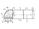
R、G、BのLEDを同時点灯してR、G、Bを混色し、白色を得る構成のバックライト構造の一つとして図22に示す構造のものが挙げられる。図22は導光板とR、G、BのLEDとの配置状況を示した要部断面図と平面図で、図22の(a)は要部断面図、図22の(b)は平面図を示している。図22の(a)において、導光板1の入射面1aである端面側に実装基板3に実装されたLED2を配置し、入射面1aから導光板1内にLED2の発光した光を取り入れている。1cは出射面で、導光板1内に入射した光はこの出射面1cから出射して液晶表示パネルの表示画像を照明する。1dは導光板1の下面で、図示はしていないが、この下面1dにはプリズムなどの反射手段が設けられていて、LED2からの入射した光を出射面1c側に反射させる働きをさせている。
A backlight structure having a structure shown in FIG. 22 is one example of a backlight structure in which R, G, and B LEDs are simultaneously turned on to obtain a white color by mixing R, G, and B colors. FIG. 22 is a cross-sectional view and plan view of the main part showing the arrangement of the light guide plate and the R, G, and B LEDs. FIG. 22 (a) is a cross-sectional view of the main part, and FIG. 22 (b) is a plan view. Is shown. In FIG. 22A, the
LED2は、図22の(b)に示すように、R、G、BのLED2が実装基板3に実装されて、導光板1の入射面1aに対面して順次並んで配置されている。このR、G、BのLED2を同時点灯して赤色光、緑色光、青色光が十分に混ざり合うと白色になる。
As shown in FIG. 22B, the
このような配置をなす導光板1と複数のR、G、BのLED2を備えたバックライトユニットは、導光板1と複数のLED2挟んで、導光板1の出射面1c側に光拡散シートとプリズムシートを積層して配設し、導光板1の下面1d側には反射シートを配設してバックライトユニットを構成している。
The backlight unit including the light guide plate 1 and the plurality of R, G, and
一般に、カラーフィルターを用いた液晶表示パネルのバックライトユニットとして用いる場合は、R、G、BのLED2を同時点灯して白色にして用いるが、R、G、Bの赤色光、緑色光、青色光の混ざり合いに不十分な部分が現れると色むら現れてくる。図23はR、G、BのLED2を同時点灯したときにおける発生する色むらの状況を模式的に表した説明図を示している。図23において、斜線で示したCの領域部分はR、G、Bの赤色光、緑色光、青色光が十分に混ざり合って白色をなした部分を示している。また、Dの領域部分は混ざり合いが不十分で色むらが現れた部分を示している。
In general, when used as a backlight unit of a liquid crystal display panel using a color filter, R, G, and
通常、LEDから発する光はLED発光正面から全方位90°の方向に向けて放射されているが、LED発光面の正面方向が発光強度が最も強く、正面からの角度がずれて行くに従って発光強度は弱くなっていく。そして、正面から50°の角度の範囲内に光強度の90%近くを占める特性を持つ。また、導光板の入射面1aに対向するところの対向面1bに向けて導波していく光は導波するに従って拡散度を増し、発光強度特性も緩和されていく。また、光拡散シートとプリズムシートなどを配設したバックライトユニットにおいては、バックライトユニット発光面での光強度の均一性を確保するため所望の光量だけを発光面から出光させるようにしている。LEDから導光板内に取り込まれた光の内一部だけをバックライトユニットから出射させる制約は導光板とプリズムシートによって行われている。導光板は一般的にアクリル樹脂やポリカーボネイト樹脂などの透明樹脂を用いていることから、これらの樹脂の屈折率により臨界角が概ね40°程度になる。導光板に取り込まれた光は臨界角が40°に近い角度で導光板の出射面に到達した光だけが導光板から出射する。また、プリズムシートも同様で、光拡散シートを通過した光の内、適した角度でプリズムシートに到達した光だけがプリズムシートを透過して発光面から出射する。つまり、導光板の入射面から入射した光は入射面と対向する対向面へ向かって導波して行くが、導波して行くに従って拡散度を増して様々な方向に向かって進む。その内、導光板とプリズムシートの制約条件を満たした特定角度の光だけがバックライトユニットの発光面から出射する。
Usually, the light emitted from the LED is emitted in the direction of 90 ° in all directions from the LED light emission front, but the light emission intensity is strongest in the front direction of the LED light emission surface, and the light emission intensity as the angle from the front shifts. Is getting weaker. And it has the characteristic which occupies nearly 90% of light intensity in the range of an angle of 50 degrees from the front. Further, the light that is guided toward the facing
図23において、X軸(横軸)方向を導光板1の奥行き方向、Y軸(縦軸)方向を導光板1の幅方向とすると、図23に示されるようにR、G、BのLED2を並べたような場合には、前述したように、対向面1bに向かって導波して行くに従って光の拡散度を増していくことから、導光板1の中央部の領域から奥方の対向面1bに向かっての領域は奥行き方向、幅方向共にR、G、Bの光が良く混ざり合うようになって、混色の度合いも均一化されるようになる。そして、Cの領域部分において、導光板1の出光面1cからはバランスの取れた光量の光が出射するようになって、均一色調の白色が得られる。
In FIG. 23, when the X-axis (horizontal axis) direction is the depth direction of the light guide plate 1 and the Y-axis (vertical axis) direction is the width direction of the light guide plate 1, as shown in FIG. As described above, the diffusion degree of light increases as the light is guided toward the
一方、色むらの現れた入射面1aに近いDの領域部分は、導波距離が短いために光の拡散度合いが少なく、LED2の光強度特性が強く現れてくる。つまり、入射面1aに近い部分は奥行き方向、幅方向共に光拡散が少なくなり、また、相隣り合う発光色の異なるLED2の光から届く発光強度は相対的に弱くなって、その混色に不均一性が生まれてくる。このため、R、G、Bの光量がそれぞれバランスの取れた状態で出射面1cから出光していないことから色むらが現れる。この様なことから、導光板1の入光面1aに近い領域においては十分に混色させることが困難になっている。
On the other hand, in the region of D near the
また、バックライトユニットの発光面で白色に見える部分で、同じ部分を10°程度斜め方向から見ると、R、G、BのLED2の光源色がそのまま出光されて色むら見えてくる。この色むらが見える原因としてはR、G、Bの3色のLED2が発光面から同等の指向特性を持った光で放射されていないことが原因と思われる。前述したように、発光面の一部分を見た場合、適した角度でプリズムシートに到達した光だけがプリズムシートを透過して発光面から出射することになるが、出射面に到達する光はLEDの実装位置により異なる入射角を持っており、該プリズムシートに適した角度であると同時に異なる軸においては異なる傾き角を持った光が出射することになり、発光面の見る角度によって色むらを発生させている。つまり、バックライトユニットの発光面方向から見た各LEDの指向特性の不一致が色むらの主要因であると言える。
In addition, when the same portion is viewed from an oblique direction of about 10 ° in the portion that appears white on the light emitting surface of the backlight unit, the light source colors of the R, G, and
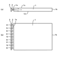
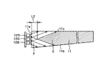
以上述べた原因で発生する色むらを解決する技術の一つに図24に示す構成(特許文献1)のものがある。図24は特許文献1に記載されたところの面状光源の一実施形態を示す側面図を示していて、基板13に実装されたR、G、BなるLED(12R、12G、12B)を導光板11の入射面11aと対面して導光板11の厚み方向に積み重ねて配置した構成をなしている。
One of the techniques for solving the color unevenness that occurs due to the above-described causes is the configuration shown in FIG. 24 (Patent Document 1). FIG. 24 is a side view showing an embodiment of a planar light source described in Patent Document 1, and leads R, G, and B LEDs (12R, 12G, and 12B) mounted on the
特許文献1によれば、R、G、BなるLED(12R、12G、12B)のそれぞれは幅方向に均一化された光を出射するので、R、G、BなるLEDを厚み方向に極近接して配置することにより導光板11の出射面11cのほぼ全域から色むらのない白色照明光を出射されるとされている。
According to Patent Document 1, each of R, G, and B LEDs (12R, 12G, and 12B) emits light that is uniformed in the width direction, so that the R, G, and B LEDs are in close proximity in the thickness direction. Thus, it is supposed that white illumination light having no color unevenness is emitted from almost the entire area of the
図25は図24に示される構成での作用を説明する模式的に示した説明図である。特許文献1に示された構成のものは、導光板11の上方から見たR、G、Bの各LEDの指向特性は同一特性になっていることから導光板11の幅方向での光の混ぜ合わせには効果的である。しかし反面、図25に示すように、厚み方向に対しては、導光板11の入射面11aでのR、G、Bの入射光は屈折を起こして集光する方向に、即ち、指向範囲が狭くなって導光板内を進むようになる。このため、光導波方向におけるR、G、Bの光の混ざり合いは入射面11aから離れた所から起きる。図25において、斜線で示したEの部分はR、G、Bの3つの光が混ざり合った領域を示していて、R、G、Bの混ざり合いで白色になった領域を示している。一方、Eの領域以外のFで示す領域はR、G、Bの3つの光が混ざり合っていない領域を示していて、白色にならない部分を示している。このFの領域部分に色むらが現れる。
FIG. 25 is an explanatory diagram schematically showing the operation of the configuration shown in FIG. In the configuration shown in Patent Document 1, the directivity characteristics of the R, G, and B LEDs seen from above the
ここで、R、G、Bの光が混ざり合うEの領域の入射面11aからの一番近い距離をL2とすると、R、G、Bの入射光が導光板31内で集光して指向範囲を狭めることから、入射面11aからの距離L2は大きくなってしまう。
Here, when the closest distance from the
また、入射面11aの極近い位置にあっては、R、G、Bの入射光が導光板11内で集光する方向で指向領域を狭めて進むことから、導光板11の下面の反射面11bや導光板11の下面側に配設される反射シートに入射する光の量は少なくなる。そして、反射面11bや反射シートからの反射光も少なくなり、R、G、Bの混ざり合う光も少なくなって、出射面11cから出射されるR、G、Bの光量に偏りが現れてくる。このようなこともあって、入射面11aの極近い所であっても色むらが現れてくる。
Further, at a position very close to the
導光板に色むらが現れる面積は、R、G、BのLEDの厚み方向の配置間隔を近接することにより小さくすることは可能ではあるが、点光源をなすLEDはパッケージ様態をなすことからR、G、BのLEDの近接間隔にも限度を有し、入射面11aの近くは3色の光の混ざり合わない部分がどうしても発生し、色むらが現れる領域の発生は避けられない。
The area in which the color unevenness appears on the light guide plate can be reduced by making the arrangement intervals in the thickness direction of the R, G, and B LEDs close to each other, but the LED that forms the point light source has a package form. , G, and B LEDs also have a limit in their proximity, and a portion where the light of the three colors does not mix is inevitably generated near the
また、このような構成を取るバックライトユニットを液晶表示パネルの背面側に備えた場合、色むらが現れる領域を液晶表示パネルの表示領域の外側にもってくるように設計しなければならない。従って、バックライトユニットの導光板の大きさを液晶表示パネルの表示領域の大きさより大きくする必要が生まれ、バックライトユニットの小型化には限度を有する。 Further, when the backlight unit having such a configuration is provided on the back side of the liquid crystal display panel, it is necessary to design the area where the color unevenness appears outside the display area of the liquid crystal display panel. Therefore, it is necessary to make the size of the light guide plate of the backlight unit larger than the size of the display area of the liquid crystal display panel, and there is a limit to downsizing the backlight unit.
本発明の目的は、上記の課題に鑑みてなされたもので、色むらの発生面積を小さくできる導光板を見出すこと、また、色むらの発生面積を小さくすると共に小型にできるバックライトユニットの構成を見出すこと、また、表示装置を小型にし、表示装置の色再現範囲を広げることを目的とするものである。 The object of the present invention has been made in view of the above problems, and finds a light guide plate capable of reducing the occurrence area of color unevenness, and the configuration of a backlight unit that can reduce the area where color unevenness occurs and can be miniaturized. In addition, the present invention aims at finding a small display device and expanding the color reproduction range of the display device.
上記の目的を達成するための手段として、本発明の請求項1に記載の導光板は、四角な略板状の形状をなして、板の側面からLEDなる光源の光を採光し、該採光した光を板の上下面の少なくともいずれかの面から放射するエッジライトタイプの導光板であって、前記LEDの光を採光する側面を入射面とし、前記光を放射する面を出射面とすると、前記導光板の入射面には前記LEDからの入射光を前記導光板の厚み方向に光を分散させる凸形状又は凹形状をなす光分散手段が複数、筋状に横に延びて平行列をなして設けられていることを特徴とするものである。 As a means for achieving the above object, the light guide plate according to claim 1 of the present invention has a substantially rectangular plate shape, and collects light from an LED light source from the side surface of the plate. An edge light type light guide plate that emits light from at least one of the upper and lower surfaces of the plate, wherein the side surface that collects the light of the LED is an incident surface, and the surface that emits the light is an output surface A plurality of convex or concave light dispersing means for dispersing incident light from the LEDs in the thickness direction of the light guide plate and extending in parallel in a streak shape on the incident surface of the light guide plate. It is characterized by being provided.
また、本発明の請求項2に記載の導光板は、前記導光板の平行列をなす光分散手段は、前記出射面と平行に設けられていることを特徴とするものである。
The light guide plate according to
また、本発明の請求項3に記載の導光板は、前記導光板の平行列をなす光分散手段は、前記出射面と傾斜をなして設けられていることを特徴とするものである。
The light guide plate according to
また、本発明の請求項4に記載の導光板は、前記導光板の平行列をなす光分散手段は、前記出射面と傾斜角がそれぞれ異なっている少なくとも2種類の平行列を有していることを特徴とするものである。 In the light guide plate according to claim 4 of the present invention, the light dispersion means forming the parallel rows of the light guide plates have at least two types of parallel rows each having a different inclination angle from the exit surface. It is characterized by this.
また、本発明の請求項5に記載の導光板は、前記導光板の平行列をなす光分散手段は、連続線状又は不連続線状に設けられていることを特徴とするものである。 The light guide plate according to claim 5 of the present invention is characterized in that the light dispersion means forming the parallel rows of the light guide plates are provided in a continuous line shape or a discontinuous line shape.
また、本発明の請求項6に記載の導光板は、前記導光板の光分散手段は、略半円形状又は三角形状をなすことを特徴とするものである。 The light guide plate according to claim 6 of the present invention is characterized in that the light dispersion means of the light guide plate has a substantially semicircular shape or a triangular shape.
また、本発明の請求項7に記載の導光板は、前記導光板の光分散手段は、厚み方向に光の分散領域を調整できることを特徴とするものである。 The light guide plate according to claim 7 of the present invention is characterized in that the light dispersion means of the light guide plate can adjust the light dispersion region in the thickness direction.
また、本発明の請求項8に記載のバックライトユニットの特徴は、放射スペクトルの最大波長が異なる複数のLEDと導光板を有するバックライトユニットにおいて、前記導光板は前記請求項1乃至7のいずれか1項に記載の導光板であって、該導光板の前記入射面の近傍に前記放射スペクトルの最大波長が異なる複数のLEDを配置したことを特徴とするものである。 The backlight unit according to claim 8 of the present invention is characterized in that the backlight unit has a plurality of LEDs and light guide plates having different maximum wavelengths of the emission spectrum, and the light guide plate is any one of the first to seventh aspects. The light guide plate according to claim 1, wherein a plurality of LEDs having different maximum wavelengths of the radiation spectrum are arranged in the vicinity of the incident surface of the light guide plate.
また、本発明の請求項9に記載のバックライトユニットの特徴は、前記放射スペクトルの最大波長が異なる複数のLEDは、前記導光板の前記入射面と対向する側面を対向面、前記入射面から前記対向面に向かう方向を光導波方向軸とし、該光導波方向軸に垂直で、且つ、前記導光板の出射面と平行な軸を第1の軸とし、該第1の軸と垂直をなして、且つ、該第1の軸を中心にして360°の範囲の中で選択した軸を第2の軸とすると、該第2の軸上に前記複数のLEDの発光面中心部を配置したことを特徴とするものである。 Further, the backlight unit according to claim 9 of the present invention is characterized in that the plurality of LEDs having different maximum wavelengths of the emission spectrum have a side surface facing the incident surface of the light guide plate as a facing surface and the incident surface. The direction toward the facing surface is the optical waveguide direction axis, the axis perpendicular to the optical waveguide direction axis and parallel to the exit surface of the light guide plate is the first axis, and is perpendicular to the first axis. In addition, assuming that the second axis is the axis selected within the range of 360 ° around the first axis, the light emitting surface central portions of the plurality of LEDs are arranged on the second axis. It is characterized by this.
また、本発明の請求項10に記載のバックライトユニットの特徴は、前記バックライトユニットの前記導光板は、前記放射スペクトルの最大波長が異なる複数のLEDごとに分けられることができ、前記LEDの数に応じて積み重ねできることを特徴とするものである。 The backlight unit according to claim 10 of the present invention is characterized in that the light guide plate of the backlight unit can be divided into a plurality of LEDs having different maximum wavelengths of the emission spectrum. It can be stacked according to the number.
また、本発明の請求項11に記載のバックライトユニットの特徴は、前記バックライトユニットの前記導光板の前記受光面に、前記導光板の出射面と平行であって前記導光板の光導波方向軸と直交をなす方向を幅方向とすると、前記放射スペクトルの最大波長が異なる複数のLEDからの入射光を前記導光板の幅方向に向かって光分散させる凸形状又は凹形状をなす第2の光分散手段が筋状に、縦に複数設けられていることを特徴とするものである。 The backlight unit according to claim 11 of the present invention is characterized in that the light receiving surface of the light guide plate of the backlight unit is parallel to the light exit surface of the light guide plate and is in the direction of light guide of the light guide plate. Assuming that the direction perpendicular to the axis is the width direction, a second shape having a convex shape or a concave shape that disperses incident light from a plurality of LEDs having different maximum wavelengths of the radiation spectrum in the width direction of the light guide plate. A plurality of light dispersing means are provided in a streak shape vertically.
また、本発明の請求項12に記載のバックライトユニットの特徴は、前記放射スペクトルの最大波長が異なる複数のLEDが前記導光板の前記入射面の近傍で複数の段に分かれて積み重ねた場合に、各段の前記LEDはそれぞれ別個の実装基板に実装されていることを特徴とするものである。 The backlight unit according to claim 12 of the present invention is characterized in that a plurality of LEDs having different maximum wavelengths of the emission spectrum are stacked in a plurality of stages in the vicinity of the incident surface of the light guide plate. The LEDs at each stage are mounted on separate mounting boards, respectively.
また、本発明の請求項13に記載のバックライトユニットの特徴は、前記バックライトユニットの放射スペクトルの最大波長が異なる複数のLEDはそれぞれ赤色と緑色と青色領域の放射スペクトルが最大波長となっていることを特徴とするものである。 Further, the backlight unit according to claim 13 of the present invention is characterized in that the plurality of LEDs having different maximum wavelengths of the emission spectrum of the backlight unit have the maximum emission spectra of red, green and blue regions, respectively. It is characterized by being.
また、本発明の請求項14に記載のバックライトユニットの特徴は、前記バックライトユニットの放射スペクトルの最大波長が異なる複数のLEDの1つに青色発光素子に蛍光体を被覆した白色系LEDを用いたことを特徴とするものである。 The backlight unit according to claim 14 of the present invention is characterized in that a white LED in which a blue light emitting element is coated with a phosphor is applied to one of a plurality of LEDs having different maximum wavelengths of the emission spectrum of the backlight unit. It is characterized by being used.
また、本発明の請求項15に記載の表示装置の特徴は、液晶表示パネルの背面側にバックライトユニットを備えた表示装置において、前記バックライトユニットは前記請求項8乃至14のいずれか1項に記載のバックライトユニットを用いたことを特徴とするものである。 Further, the display device according to claim 15 of the present invention is characterized in that in the display device having a backlight unit on the back side of the liquid crystal display panel, the backlight unit is any one of the above claims 8 to 14. The backlight unit described in 1 is used.
本発明によれば、以下の発明効果が得られる。最初に、請求項1〜7に記載の導光板の発明効果は次のような効果が得られる。本発明の導光板はエッジライト方式の導光板であることから、導光板の側面から光源の光を採光する。そして、導光板の入射面にLEDからの入射光を導光板の厚み方向に光を分散させる凸形状又は凹形状をなす光分散手段が複数、筋状に横に延びて平行列をなして設けられている。凸形状又は凹形状をなす光分散手段は凸や凹の境界面で光の屈折が起き、光を分散させるので光分散手段として効果的に作用する。また、複数、筋状に横に延びて平行列をなしているとLEDからの入射光が厚み方向に分散を起こす。厚み方向の分散により導光板内では厚み方向に広角的に光の広がりをもって進む。即ち、厚み方向への異方性分散特性が生まれる。このため、入射面の極近傍にあっても、導光板の下面に設けたプリズムなどの反射手段や導光板の下面側に配設した反射シートなどに光が入射し、そこからの反射光が生まれる。そして、これらの反射光の一部は屈折などによって拡散されて、入射面の極近傍でも拡散光が増える。そして、出射条件角度(臨界角)を満たした拡散光は導光板の出射面から出射する。入射面の極近傍でも拡散した光が出射するようになるので入射面の近傍で発生する色むらは少なく抑えられる。そして、平行列をなしていると、例えば、発光色の異なる光が同時に入射した場合などはどの光も同じ方向に分散させ、光の混ざり合いが積極的に進められるようになる。 According to the present invention, the following invention effects can be obtained. First, the invention effects of the light guide plates according to claims 1 to 7 are as follows. Since the light guide plate of the present invention is an edge light type light guide plate, light from the light source is collected from the side surface of the light guide plate. A plurality of light dispersing means having a convex shape or a concave shape for dispersing the light incident from the LED in the thickness direction of the light guide plate is provided on the incident surface of the light guide plate so as to extend horizontally in parallel lines. It has been. The light dispersing means having a convex shape or a concave shape effectively acts as a light dispersing means because light is refracted at the boundary surface of the convex or concave to disperse the light. In addition, when a plurality of stripes extend horizontally in a parallel row, incident light from the LED is dispersed in the thickness direction. Due to the dispersion in the thickness direction, the light guide plate spreads in the thickness direction with a wide spread of light in the light guide plate. That is, anisotropic dispersion characteristics in the thickness direction are born. For this reason, even in the very vicinity of the incident surface, light enters the reflecting means such as a prism provided on the lower surface of the light guide plate or a reflective sheet disposed on the lower surface side of the light guide plate. to be born. A part of the reflected light is diffused by refraction or the like, and the diffused light increases in the vicinity of the incident surface. Then, the diffused light that satisfies the emission condition angle (critical angle) is emitted from the emission surface of the light guide plate. Since diffused light is emitted even in the vicinity of the incident surface, color unevenness generated in the vicinity of the incident surface can be reduced. When the parallel rows are formed, for example, when lights having different emission colors are incident at the same time, all the lights are dispersed in the same direction, and the mixing of the light is actively promoted.
ここで、平行列をなす光分散手段が出射面と平行に設けられていると、入射光の多くは厚み方向に分散する。また、平行列をなす光分散手段が出射面と傾斜をなして設けられていると、厚み方向の分散のみならず幅方向の分散も現れてくる。出射面との傾斜角度で分散方向を調整することも可能になってきて、異方性分散の方向性を決めることもできる。また、平行列をなす光分散手段に出射面と傾斜角がそれぞれ異なっている少なくとも2種類の平行列を有すると、厚み方向での分散方向と幅方向での分散方向を適宜に調整することが可能になり、また、厚み、幅両方向でのバランスの取れた光分散も可能になる。このように、厚み方向のみならず幅方向にも光が分散するようになると色むらの現れる面積を更に小さくする効果を生む。 Here, if the light dispersion means forming parallel rows are provided in parallel with the emission surface, most of the incident light is dispersed in the thickness direction. In addition, when the light dispersion means forming parallel rows are provided so as to be inclined with respect to the emission surface, not only dispersion in the thickness direction but also dispersion in the width direction appears. It has become possible to adjust the dispersion direction by the inclination angle with respect to the emission surface, and the directionality of anisotropic dispersion can be determined. Further, if the light dispersing means forming the parallel rows has at least two kinds of parallel rows each having a different inclination angle from the exit surface, the dispersion direction in the thickness direction and the dispersion direction in the width direction can be adjusted appropriately. In addition, balanced light dispersion in both the thickness and width directions is possible. As described above, when light is dispersed not only in the thickness direction but also in the width direction, an effect of further reducing the area in which color unevenness appears is produced.
また、平行列をなす光分散手段が連続線状になっていると光分散手段の面に入射する光は全て分散されるようになる。また、光分散手段が不連続線状になっていると光分散手段が有る部分と光分散手段が無い部分とで構成されるので、光分散手段が有る部分では入射光は広角的に分散して進み、光分散手段の無い部分では入射光は集光するようにして指向範囲を狭めて進むようになる。このことによって、分散光量の調整も可能になってきて、出射面からの出射光量の均一性の調整にも役立てることが可能になる。また、不連続線状をなす場合、光分散手段の形状によっては厚み、幅両方向に光分散させることも可能になる。 Further, if the light dispersing means forming the parallel rows are continuous, all the light incident on the surface of the light dispersing means is dispersed. In addition, when the light dispersion means is in a discontinuous line, it is composed of a part with the light dispersion means and a part without the light dispersion means, so that the incident light is dispersed at a wide angle in the part with the light dispersion means. In a portion where there is no light dispersion means, the incident light is condensed so as to narrow the directing range. This makes it possible to adjust the amount of dispersed light, which can also be used to adjust the uniformity of the amount of light emitted from the exit surface. In the case of a discontinuous line shape, depending on the shape of the light dispersion means, it is possible to disperse light in both the thickness and width directions.
また、凸形状または凹形状をなす光分散手段は略半円形状または三角形状をなす。ここでの略半円形状は円形や楕円形などの曲面形状持ったものとして定義するものであるが、略半円形状の曲面は光の入射位置が異なると屈折角も異なってくるので、分散光の分散分布に偏りが発生せずに一様な分布を持たせて分散させることができる。また、三角形状の場合も略半円形状の場合の効果に近い効果を得ることができる。また、略半円形状や三角形状は形状が比較的シンプルであることから、導光板を射出成形で形成する場合における金型の製作が容易となり、また、射出成形での成形性も容易にできる効果を生む。 The light dispersing means having a convex shape or a concave shape has a substantially semicircular shape or a triangular shape. The semi-circular shape here is defined as having a curved shape such as a circle or ellipse, but the semi-circular curved surface has different refraction angles depending on the incident position of light. It is possible to disperse the light with a uniform distribution without causing a bias in the light distribution. Also, in the case of a triangular shape, an effect close to that of a substantially semicircular shape can be obtained. In addition, since the semi-circular shape and the triangular shape are relatively simple, it is easy to manufacture a mold when the light guide plate is formed by injection molding, and the moldability by injection molding can also be facilitated. Produce an effect.
また、光分散手段は厚み方向に光の分散領域を調整できるようになっている。この分散領域の調整は、例えば、光分散手段の形状が略半円形状であれば曲率半径を変えることによって分散領域が調整できる。また、三角形状で有れば谷または山を挟む2辺の傾斜角を変えるか、または、傾斜角が異なる複数の三角形状を混在させることによって分散領域が調整できる。このように光の分散領域が調整できるようになれば色むらの発生する面積を調整できるようになり、色むらの発生面積を小さく抑えることができる。 In addition, the light dispersion means can adjust the light dispersion region in the thickness direction. The dispersion region can be adjusted, for example, by changing the radius of curvature if the shape of the light dispersion means is a substantially semicircular shape. Moreover, if it is a triangle shape, a dispersion | distribution area | region can be adjusted by changing the inclination angle of 2 sides which pinches | interposes a trough or a mountain, or mixing several triangle shape from which an inclination angle differs. If the light dispersion region can be adjusted in this way, the area where color unevenness occurs can be adjusted, and the area where color unevenness occurs can be kept small.
以上の効果を生む導光板は発光色の異なる複数のLEDを用いての混色を行う場合に優れた効果を生む。例えば、前述の従来技術でのR、G、BのLEDを重ねて配置した場合におけるR、G、Bの混色で白色を得る構成の場合などには優れた成果を得ることができ、色むらの発生する面積を小さくして白色が得られる面積を大きく広げる効果を得る。 The light guide plate producing the above effects produces an excellent effect when performing color mixing using a plurality of LEDs having different emission colors. For example, excellent results can be obtained in the case of a configuration in which white color is obtained by mixing R, G, and B in the case where the R, G, and B LEDs in the above-described conventional technique are stacked, and color unevenness is obtained. The effect of reducing the area where the light is generated and increasing the area where white can be obtained is obtained.
次に、請求項8〜14に記載のバックライトユニットの発明効果は次のような効果が得られる。一般に、エッジライト方式のバックライトユニットは、導光板の側面に光源であるLEDを配置し、導光板の下面側に反射シート、導光板の出射面側に拡散シートとプリズムシートなどを積層して構成している。このような構成をなすバックライトユニットにおいて、請求項8に記載のバックライトユニットは、本発明の導光板の入射面の近傍に放射スペクトルの最大波長が異なる複数のLEDを配置する。発光色の異なる複数のLEDからの光が前述した如く導光板の厚み方向に広角的に分散して混ざり合い、入射面の近傍でも混色が起きるようになる。また、請求項9に記載のLEDの配置形態をなすと、例えば、第2の軸に導光板の入射面に平行で好適な位置のものを1つ選択し、その軸上に複数のLEDを配置すると、発光色の異なる複数のLEDが積み重なった状態で入射面と等距離をおいて配置される配置形態ができる。また、第2の軸に導光板の入射面に垂直で好適な位置のものを1つ選択し、その軸上に複数のLEDを配置すると、複数のLEDが平面的に並んだ状態の配置形態になる。また、第2の軸に入射面と傾きを持った好適な位置のものを選択し、その軸上に複数のLEDを配置すると、複数のLEDは階段状に配置された配置形態となる。LEDの放射光は概ね同じ指向範囲をもって放射されるので、このような配置形態をなすと厚み方向での光の混ざり合いを施すことで十分な混色が行われる。
本発明の導光板を用いるのに好適なLEDの配置形態となり、大きな効果が得られる。例えば、R、G、BのLEDを用いれば十分に混色されての白色なる光が得られる。
Next, the invention effects of the backlight units according to claims 8 to 14 are as follows. In general, an edge-light type backlight unit has an LED as a light source arranged on the side of a light guide plate, a reflection sheet on the lower surface side of the light guide plate, and a diffusion sheet and a prism sheet laminated on the output surface side of the light guide plate. It is composed. In the backlight unit having such a configuration, the backlight unit according to claim 8 includes a plurality of LEDs having different maximum wavelengths of the emission spectrum in the vicinity of the incident surface of the light guide plate of the present invention. As described above, light from a plurality of LEDs having different emission colors is dispersed and mixed in a wide-angle direction in the thickness direction of the light guide plate, and color mixing occurs near the incident surface. Further, when the LED is arranged in the ninth aspect, for example, one having a suitable position parallel to the incident surface of the light guide plate is selected as the second axis, and a plurality of LEDs are arranged on the axis. If it arrange | positions, the arrangement | positioning form which arrange | positions at equal distance with an entrance plane in the state in which several LED from which luminescent color differs was piled up can be performed. Further, when one LED having a suitable position perpendicular to the incident surface of the light guide plate is selected on the second axis and a plurality of LEDs are arranged on the axis, the arrangement form in which the plurality of LEDs are arranged in a plane become. Further, when a suitable position having an incident surface and an inclination on the second axis is selected and a plurality of LEDs are arranged on the axis, the plurality of LEDs are arranged in a staircase pattern. Since the emitted light of the LED is radiated with substantially the same directivity range, if such an arrangement is made, sufficient color mixing is performed by mixing the light in the thickness direction.
It becomes the arrangement form of LED suitable for using the light guide plate of the present invention, and a great effect is obtained. For example, if R, G, and B LEDs are used, white light that is sufficiently mixed in color can be obtained.
ここで、本発明のバックライトユニットの導光板は、放射スペクトルの最大波長が異なる複数のLEDごとに分けられることができる。その分けられる導光板を分割導光板と呼ぶと、その分割導光板をLEDの数に応じて積み重ねて導光板を形成する。近年における薄型化の市場ニーズなどにより、白色発光のLEDと薄型の導光板を用いて薄型バックライトユニットを構成することが行われている。この薄型バックライトユニットの導光板に光分散手段を追加することによって流用して使用することができる。この場合、金型の一部の金型部品を入れ替え交換することによって導光板の製作が可能になる。例えば、光分散手段の仕様を設けた金型の入れ子部品を入れ替えることによって達成できる。このような構成を取ると、金型費用は安く上がり、金型費用の削減効果が得られる。また、分割導光板を積み重ねることによって重ね合わせ目に空気層が生まれる。この空気層が光の屈折を発生させて光の拡散を生み出し、複数のLEDの光の混ざり合いが一層進むようになる。 Here, the light guide plate of the backlight unit of the present invention can be divided into a plurality of LEDs having different maximum wavelengths of the emission spectrum. When the divided light guide plates are called divided light guide plates, the divided light guide plates are stacked according to the number of LEDs to form the light guide plate. In recent years, a thin backlight unit is configured by using a white light emitting LED and a thin light guide plate due to market needs for thinning. It can be used by adding a light dispersion means to the light guide plate of the thin backlight unit. In this case, the light guide plate can be manufactured by exchanging and exchanging some mold parts of the mold. For example, this can be achieved by replacing the mold nesting part provided with the specifications of the light dispersion means. With such a configuration, the cost of the mold is increased and an effect of reducing the mold cost can be obtained. Further, by stacking the divided light guide plates, an air layer is created at the overlap. This air layer generates light refraction to create light diffusion, and the mixing of the light from the plurality of LEDs further proceeds.
また、導光板に厚み方向に光を分散させる光分散手段の他に、幅方向に光を分散させる第2の光分散手段を設けることにより、LEDからの入射光を厚み方向のみならず幅方向にも分散させることができる。厚み、幅両方向での光分散により厚み方向の混色と幅方向の混色が行われて色むらの発生面積を更に小さくする効果を得る。 In addition to the light dispersion means for dispersing the light in the thickness direction on the light guide plate, the second light dispersion means for dispersing the light in the width direction is provided, so that the incident light from the LED is not only in the thickness direction but also in the width direction. Can also be dispersed. By the light dispersion in both the thickness and width directions, color mixing in the thickness direction and color mixing in the width direction are performed, thereby obtaining an effect of further reducing the color unevenness generation area.
また、複数のLEDを複数の段に分かれて積み重ねた場合に、各段のLEDをそれぞれ別個の実装基板に実装するようにする。この場合、LEDの厚みが薄い場合は効果的で、それぞれ別個の実装基板は幅を狭くして用いることができ、LEDを配置する導光板の側面の配置スペースが狭い場合でも配置することができるようになる。1つの実装基板の幅方向に複数のLEDを並べて実装する場合は実装基板の幅は広い幅が必要とされる。実装基板の幅が広くなると広い配置スペースが必要とされ、導光板の側面に配置するのに場合によってはスペース不足が生じる。特に、幅の大きさが大きいLEDを使う場合にはこのようなスペース問題が生じる。幅は大きくても厚みが薄い場合は、それぞれ別個の実装基板に実装して配置するようにすると、この問題は解消される。また、導光板の入射面の中央部にR、G、BのLEDがかたまって配置される状態になって、十分な混色が得られ易くなる。 In addition, when a plurality of LEDs are stacked in a plurality of stages, each stage of LEDs is mounted on a separate mounting board. In this case, it is effective when the thickness of the LED is thin, each separate mounting substrate can be used with a narrow width, and can be arranged even when the arrangement space on the side surface of the light guide plate on which the LED is arranged is narrow. It becomes like this. When mounting a plurality of LEDs side by side in the width direction of one mounting substrate, the mounting substrate needs to have a wide width. When the width of the mounting substrate is increased, a wide arrangement space is required, and there is a shortage of space depending on the case when it is arranged on the side surface of the light guide plate. In particular, when an LED having a large width is used, such a space problem occurs. If the width is large but the thickness is small, this problem can be solved by mounting and arranging them on separate mounting boards. In addition, the R, G, and B LEDs are arranged in the center of the incident surface of the light guide plate, so that sufficient color mixing is easily obtained.
また、放射スペクトルの最大波長が異なる複数のLEDは赤色(R)発光のLED、緑色(G)発光のLED、青色(B)発光のLEDを用いる。R、G、BのLEDを同時に発光させるとR、G、Bの光が混ざり合って白色が得られる。R、G、BのLEDを用いることで、白色発光のLEDや冷陰極蛍光管の光源では実現困難であった濃い赤色や緑色の色調が得られ、表示装置の色再現範囲の拡大が得られる。また、R、G、BのLEDを高速で順次点灯して画像表示を行うフィールドシーケンシャルカラー方式の表示装置に用いるとあらゆる色調の画像を出現させることができる。 The plurality of LEDs having different maximum wavelengths in the emission spectrum are red (R) light emitting LEDs, green (G) light emitting LEDs, and blue (B) light emitting LEDs. When the R, G, and B LEDs are caused to emit light at the same time, the R, G, and B lights are mixed to obtain a white color. By using R, G, and B LEDs, it is possible to obtain dark red and green color tones that were difficult to achieve with white light emitting LEDs and cold cathode fluorescent tube light sources, and to expand the color reproduction range of display devices. . In addition, when used in a field sequential color display device that displays images by sequentially turning on LEDs of R, G, and B at high speed, images of all colors can appear.
また、放射スペクトルの最大波長が異なる複数のLEDの1つに青色発光素子に蛍光体を被覆した白色系LEDを用い、例えば、この白色系LEDとRのLEDを組み合わせた場合には2種類のLEDで表示装置の色再現範囲の拡大効果を得る。また、2種類のLEDで良いので導光板も薄くでき、バックライトユニットの薄型化が可能になる。 In addition, when a white LED in which a phosphor is coated on a blue light emitting element is used as one of a plurality of LEDs having different maximum wavelengths of the emission spectrum, for example, when this white LED and an R LED are combined, two types of LEDs are used. The effect of expanding the color reproduction range of the display device is obtained with the LED. Further, since two kinds of LEDs are sufficient, the light guide plate can be made thin, and the backlight unit can be made thin.
以上の構成をなすことにより、導光板の色むらの発生する面積を小さく抑えて白色の面積を大きくする。バックライトユニットは導光板の出射面側に拡散シートを配設し、導光板の出射光を更に著しく拡散させる。そして、プリズムシートの出射条件を満たした光がバックライトユニットの発光面から出射する。そのため、拡散シートの作用などの影響も受けて、発光面での色むらは殆ど視認されなくなる。また、白色なる発光面の面積も大きくする効果を生む。これによって、表示装置の画像表示面積をバックライトユニットの白色面積に合わせて大きくすることが可能になるが、画像表示面積は変わらないとした場合にはバックライトユニットの大きさを小さくすることが可能になる。即ち、バックライトユニットの小型化が可能になる。また、LEDに白色系LEDとRのLEDを用いた構成の場合やR、G、BのLEDを平面的に並べて反射部材を介してLEDの光を導光板に入射させる構成の場合などは導光板を薄くできるのでバックライトユニットの薄型化も可能になる。 With the above-described configuration, the area where the color unevenness of the light guide plate is generated is suppressed to be small, and the white area is increased. In the backlight unit, a diffusion sheet is disposed on the exit surface side of the light guide plate, and the light emitted from the light guide plate is further diffused significantly. And the light which satisfy | filled the emission conditions of a prism sheet radiate | emits from the light emission surface of a backlight unit. Therefore, color unevenness on the light emitting surface is hardly visually recognized due to the effect of the diffusion sheet. In addition, an effect of increasing the area of the light emitting surface that becomes white is produced. This makes it possible to increase the image display area of the display device in accordance with the white area of the backlight unit, but if the image display area does not change, the size of the backlight unit can be reduced. It becomes possible. That is, the backlight unit can be downsized. Also, in the case of a configuration using white LEDs and R LEDs as LEDs, or in a configuration in which R, G, B LEDs are arranged in a plane and the light of the LED is incident on the light guide plate through a reflecting member, etc. Since the light plate can be made thinner, the backlight unit can be made thinner.
また、従来技術においては、白色をなす部分でも、同じ部分を10°程度斜め方向から見たときにLEDの光源色がそのまま出光されて色むら見える現象が現れたが、導光板に厚み方向に光を分散させる光分散手段を設けた本発明の構成においてはこのような現象は現れない。 Further, in the prior art, even when the white part is viewed from an oblique direction of about 10 °, the light source color of the LED is emitted as it is and the color appears uneven. Such a phenomenon does not appear in the configuration of the present invention provided with the light dispersion means for dispersing the light.
そして、以上述べたバックライトユニットを液晶表示パネルの背面側に備えることにより、色むらの視認されない、そして、色再現範囲が広められた表示装置が得られる。また、バックライトユニットが小型にできることから表示装置自体もそれに合わせて小型にできる効果を生む。 By providing the backlight unit described above on the back side of the liquid crystal display panel, a display device in which color unevenness is not visually recognized and the color reproduction range is widened can be obtained. Further, since the backlight unit can be reduced in size, the display device itself can be reduced in size accordingly.
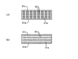
(第1実施形態)以下、本発明を実施するための最良の形態(以降、実施形態と云う)について図を用いながら説明する。最初に、第1実施形態として本発明の導光板について図1〜図7を用いながら説明する。ここで図の説明を行う。図1は本発明の第1実施形態に係る導光板の斜視図を示している。また、図2は図1における導光板の要部断面図で、LEDの配置も含めたもので示している。尚、LEDは2点鎖線で表示しているが、このLEDの配置は配置状態の1例を示したものである。図3は図1における導光板の光分散手段の作用を模式的に示した説明図である。また、図4はLED配置と導光板との作用関係を模式的に示した説明図である。また、図5は平行列をなす光分散手段の他の様態を示した平面図で、図5の(a)は平行列が出射面と傾斜をなした様態、図5の(b)は平行列が出射面とそれぞれ異なる傾斜角を持った2種類の平行列を設けた様態を示している。また、図6は不連続線状の形態をなす光分散手段の平面図で、図6の(a)は切れ目が設けられた様態の平面図、図6の(b)はドット状に設けられた様態の平面図を示している。また、図7は導光板の平板以外の形状を示す導光板の要部断面図を示していて、図7の(a)は入射面の部位の所の厚みが厚くなっている形状のもの、図7の(b)は下面が傾斜面をなしている形状のものを示している。 (First Embodiment) The best mode for carrying out the present invention (hereinafter referred to as an embodiment) will be described below with reference to the drawings. First, the light guide plate of the present invention will be described as a first embodiment with reference to FIGS. Here, the figure will be described. FIG. 1 is a perspective view of a light guide plate according to the first embodiment of the present invention. FIG. 2 is a cross-sectional view of the main part of the light guide plate in FIG. 1 and includes the arrangement of the LEDs. In addition, although LED is displayed with the dashed-two dotted line, this arrangement | positioning of LED shows an example of an arrangement | positioning state. FIG. 3 is an explanatory view schematically showing the operation of the light dispersion means of the light guide plate in FIG. FIG. 4 is an explanatory diagram schematically showing the operational relationship between the LED arrangement and the light guide plate. FIG. 5 is a plan view showing another aspect of the light dispersing means in parallel rows, FIG. 5 (a) is a view in which the parallel rows are inclined with respect to the exit surface, and FIG. This shows a mode in which the matrix has two types of parallel rows each having an inclination angle different from that of the exit surface. FIG. 6 is a plan view of the light dispersion means having a discontinuous line shape. FIG. 6 (a) is a plan view showing a state in which cuts are provided, and FIG. 6 (b) is provided in a dot shape. FIG. Further, FIG. 7 shows a cross-sectional view of the main part of the light guide plate showing a shape other than the flat plate of the light guide plate, and FIG. 7 (a) shows a shape in which the thickness at the site of the incident surface is increased, FIG. 7B shows a shape in which the lower surface forms an inclined surface.
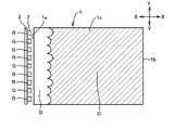
本発明の第1実施形態に係る導光板31は、図1、図2に示すように、厚みTの四角な板の形状をなしていて、側面の31aをLEDからの光の入射面としている。この入射面31aで光源であるLED35からの光を採光している。また、上面の31cを出射面31cとしている。この出射面31cからは導光板31内の光が出射するようになっている。側面の入射面31aからLED35の光を採光し、出射面31cから光を放射するエッジライトタイプの導光板をなしている。また、図2において、2点鎖線で示した35はLEDを示しており、35Rは赤色発光のLED、35Gは緑色発光のLED、35Bは青色発光のLEDを示している。このLED35の配置は、LEDの配置状態を示す1例として挙げたもので、必ずしもこの配置に限るものではない。また、LEDもR、G、Bの3種類のものに限るものではなく、発光色が1種類のLEDや発光色が異なる2種類のLEDものでも適用できるものである。第1実施形態においては、R、G、Bの3つのLED35が導光板31の厚み方向に積み重なるようにして配置したものを取り上げて説明することにする。
As shown in FIGS. 1 and 2, the
第1実施形態の導光板31は、図1、2に示すように、導光板31の入射面31aに凹形状をなす光分散手段32が複数、筋状に横に延びて、平行列をなして設けられている。この光分散手段32はLED35からの光を厚み(T)方向に光を分散させるために設けており、光分散手段32の平行列は導光板31の出射面31cと平行になるように設けている。第1実施形態の光分散手段32は凹形状をなしているが、これは、半円形での凹溝をなしているものである。この半円形での凹溝は、数μm〜数10μmの幅のものであるが、分かり易くするために大きく誇張して描いてある。尚、図示はしていないが、出射面31cと対向する下面31dにはプリズムなどによる反射手段が設けられている。
As shown in FIGS. 1 and 2, the
次に、半円形をなす光分散手段32の作用について図3を用いて説明する。半円形なる光分散手段32の曲面なる境界面31fに入射した光P1、P2、P3、P4は屈折を起こして導光板31内の矢印の方向に進む。即ち、光P1、P2、P3、P4は境界面での屈折によりそれぞれ矢印で示した厚み方向Tに向かって広角的に広がりをなして進み、光の分散が現れる。境界面31fは曲面をなしていることから分散光に偏りがない状態での一様な状態で厚み方向に分散する。これによって、LEDからの入射光は厚み方向への指向範囲に広がりをもって、即ち、厚み方向への異方性分散特性を持って導光板31内を進行する。
Next, the operation of the semicircular light dispersion means 32 will be described with reference to FIG. The light P1, P2, P3, P4 incident on the
光分散手段32は、第1実施形態においては半円形の凹形状をなしたが、光の屈折によって分散作用を生む凸形状や凹形状に仕立てるのが良く、その中で略半円形状のものや傾斜角が異なる複数の三角形状を混在させるものが一様な分散が得られるので好ましい。尚、本発明においては、半円形や半楕円形などのなだらかな曲面をなすものが最も好ましい効果を得るので、これらの形状を含めて略半円形状と定義付けしている。また、導光板31はアクリル樹脂やポリカーボネイト樹脂などの材料を用いて射出成形方法で形成している。略半円形状や三角形状はシンプルな形状をなしているので、導光板31を射出成形金型で成形する上において金型製作も容易であり、また、射出成形も容易にできると云うメリットも得る。
The light dispersion means 32 has a semicircular concave shape in the first embodiment, but it is preferable to prepare a convex shape or a concave shape that produces a dispersing action by light refraction, and among them, a substantially semicircular shape. Or a mixture of a plurality of triangular shapes having different inclination angles is preferable because uniform dispersion can be obtained. In the present invention, a smooth curved surface such as a semicircular shape or a semielliptical shape provides the most preferable effect. Therefore, the shape including these shapes is defined as a substantially semicircular shape. The
光分散手段32をなすところの半円形の凹溝はその曲率半径を変化させることによって光の厚み方向への分散領域を調整することができる。例えば、曲率半径を大きくすると分散領域は狭くなり、曲率半径を小さくすると分散領域は広くなる。これは、光分散手段32に三角形状を取った場合も同じで、2つの傾斜面に挟まれた谷の角度を大きくすると傾斜面の角度は鈍角になって分散領域は狭くなり、谷の角度を小さくすると傾斜面の角度は鋭角になって分散領域は広くなる。 The semicircular concave groove forming the light dispersion means 32 can adjust the dispersion region in the light thickness direction by changing the radius of curvature. For example, when the radius of curvature is increased, the dispersed region is narrowed, and when the radius of curvature is decreased, the dispersed region is widened. This is the same when the light dispersion means 32 has a triangular shape. If the angle of the valley sandwiched between the two inclined surfaces is increased, the angle of the inclined surface becomes obtuse and the dispersion region becomes narrower. If the angle is made smaller, the angle of the inclined surface becomes acute and the dispersion region becomes wider.
このような作用をなす光分散手段32を導光板31の入射面31aに設けた場合に、どのような効果が得られるかについて図4を用いて説明する。尚、図4においては、LEDの配置状態は1例としてR、G、BのLED35を厚み方向に積み重ねた配置のもので説明する。R(赤色)、G(緑色)、B(青色)の発光色が混ざり合うと白色になるが、図4において、斜線で示したEの領域はR、G、Bが混ざり合って白色になった領域を示している。一方、斜線のEの領域以外のFで示した領域は単色または2色が混ざり合った領域で、白色にはならず他の発色を帯びた色が現れる。
With reference to FIG. 4, what effect can be obtained when the light dispersing means 32 having such an action is provided on the
図4に示すように、R、G、BのLED35からの3色の光は導光板31の入射面31aに設けた光分散手段32によって屈折を起こし、厚み方向に広角的に分散して導光板31内を進行する。このため、R、G、Bの3色の光の混ざり合いは入射面31aの極近傍の距離L1から始まる。更に、R、G、Bの3色の光は、入射面31aに極近傍な位置にあっても、下面31dのプリズムなどの反射手段にも入射し、また、下面31dの反射手段を透過した光は導光板31の下面側に配設してある反射シート(図示はしていない)にも入射する。そして、下面31dの反射手段からの反射光や反射シートからの反射光が発生し、それらの反射光が再び導光板31内を拡散しながら進む。そして、入射面31aの極近傍に位置にあっても、R、G、Bの光が拡散して混ざり合った光量が多く現れ、臨界角による出射条件を満たした光が出射面31cから外に向かって出射する。従って、入射面31aの極近傍に位置にあっても、R、G、Bの3色の混ざり合っての白色をなす出射光量が多く現れてくる。
As shown in FIG. 4, the three colors of light from the R, G, and
導光板に光分散手段を設けていない場合については前述の背景技術で述べた通りであるが、光分散手段を設けた場合と設けていない場合とでは格段とした差異が現れ、光分散手段を設けることによってR、G、Bの3色の光が混ざり合って白色になる面積は著しく増大する。また、後述することではあるが、このような光分散手段を設けた導光板を用いてバックライトユニットを構成すると、バックライトユニットの他の構成部品の作用などの影響も受けて色むらの発生は殆どなくなる効果を得る。 The case where the light dispersion means is not provided on the light guide plate is as described in the background art above, but a remarkable difference appears between the case where the light dispersion means is provided and the case where the light dispersion means is not provided. By providing the light, the area where the light of the three colors R, G, and B is mixed and becomes white is remarkably increased. In addition, as will be described later, when a backlight unit is configured using a light guide plate provided with such light dispersion means, color unevenness occurs due to the effects of other components of the backlight unit. Has the effect of almost disappearing.
また、導光板31の入射面31aに設ける光分散手段32は広角的に分散する光の分散領域を調整することができる。導光板31の出射面31cからは均一な光量が広い面積で出射するのが望ましい。分散領域を極端に広げると導光板31の奥の方に十分光が行き届かないことも現れる。導光板31の出射面31cからは3色が十分に混ざり合っての均一な光量が広い面積で出射するように光の分散領域を適宜に設定するのが好ましい。
Further, the light dispersion means 32 provided on the
図4ではR、G、Bの3種類のLED35を積み重ねて混色を行う場合について説明したが、発光色が1種類のLEDを用いた構成でも、或いは発光色の異なる2種類のLEDを用いた構成でも適用できる。例えば、白色発光のLEDを用い構成では、LEDからの白色出射光は光分散手段によって厚み方向に広角的に分散して導光板31内を進行する。そして、出射面からの白色光の出射領域を広げる効果を生む。
In FIG. 4, the case where color mixing is performed by stacking three types of
以上、光分散手段32による作用、効果を詳しく説明した。一般に、導光板とLEDを用いたバックライトユニットは導光板の下面側に反射シートを配設し、導光板の上面側には拡散シートやプリズムシートなどを積層して配設する。そして、導光板から出射した光を拡散シートによって拡散し、そして、プリズムシートの透過条件を満たした光だけがバックライトユニットから出射する。導光板31の出射面31cから広い面積をもって出射したR、G、Bの3色混ざり合っての白色をなす光は拡散シートによって更に拡散される。これらのことにより、バックライトユニットの発光面からはR、G、Bの光が十分混色しての白色をなした光が出射するようになる。このため、バックライトユニットの発光面には色むらは殆ど現れなくなる。検証の結果では、導光板が14インチサイズのものにR、G、Bの3種類のLEDを3段に配置して、それを75組用いたバックライトユニットは、発光面の中心輝度が3000cd/m2程度、発光面の輝度均一性が80%程度得られ、発光面中央部の混色された白色のxyの色度を基準にして発光面全域のxy色度を測定すると、色度差は±0.01未満の結果が得られた。このような結果から、色むらは視認されず均一な白色をなすバックライトユニットが得られている。また、比較例として、光分散手段を設けていない場合のバックライトユニットの色度差は±0.02〜0.05程度の色度差が現れ、目視によって明らかに色むらが視認されるものであった。このような結果から、導光板に厚み方向の光分散手段を入射面に設けた導光板を用いてバックライトユニットを構成すると、色むらが殆ど現れないバックライトユニットが得られる。
The operation and effect of the light dispersion means 32 have been described in detail above. In general, in a backlight unit using a light guide plate and LEDs, a reflection sheet is provided on the lower surface side of the light guide plate, and a diffusion sheet, a prism sheet, or the like is provided on the upper surface side of the light guide plate. Then, the light emitted from the light guide plate is diffused by the diffusion sheet, and only the light satisfying the transmission condition of the prism sheet is emitted from the backlight unit. The white light mixed with the three colors of R, G, and B emitted from the
また、このバックライトユニットは表示パネルの背面側に配設して用いられるが、このバックライトユニットの白色をなす面積が大きくなると、それに合わせて表示パネルの画像表示面積を大きくすることが可能になる。表示パネルや画像表示面積は概ね製品仕様によって設定されることから、画像表示面積が変わらないとするならばバックライトユニットの大きさを小さくすることが可能になる。即ち、バックライトユニットを小型にすることができ、小型化が可能になる。 Also, this backlight unit is used by being arranged on the back side of the display panel. If the white area of the backlight unit increases, the image display area of the display panel can be increased accordingly. Become. Since the display panel and the image display area are generally set according to product specifications, the size of the backlight unit can be reduced if the image display area does not change. That is, the backlight unit can be reduced in size and can be reduced in size.
第1実施形態での光分散手段32は、導光板31の厚み方向に光を分散させるために、半円形状での凹溝をなし、出射面31cと平行に平行列をなして形成した。本発明における厚み方向の光分散手段は出射面31cに平行な平行列に限らず、図5の(a)や図5の(b)に示す様態の光分散手段も適用するもので、何れも厚み方向の分散を起こす。尚、図5は分かり易くするために模式的に描いてある。
In order to disperse light in the thickness direction of the
図5の(a)に示した平行列をなす光分散手段32は、出射面31cと傾斜(傾斜角θ)を持った平行列をなしている。ここでの光分散手段32は、前述の第1実施形態と同様に、半円形での凹溝をなしているものである。出射面31cと傾斜角θを持った光分散手段32は、この光分散手段32に入射した光を厚み方向と幅方向の両方の方向性を持って屈折させる。そして、厚み方向と幅方向の両方の方向性を持った分散光となって導光板31内を進行する。傾斜角θによって分散の方向性が変わってくるが、傾斜角θが小さいと幅方向よりも厚み方向への分散領域が大きくなってくる。逆に、傾斜角θが大きくなると厚み方向よりもむしろ幅方向への分散領域が大きくなってくる。本発明は厚み方向の光分散を目的としているので傾斜角θは45度以下に抑えるのが好ましい。
The light dispersion means 32 forming a parallel row shown in FIG. 5A forms a parallel row having an inclination (inclination angle θ) with the
次に、図5の(b)に示した平行列をなす光分散手段は平行列をなす光分散手段が2種類あって、その2種類の平行列をなす光分散手段が混ざり合った様態を示している。1種類の平行列をなす光分散手段は32Aの光分散手段で、この光分散手段32Aは出射面31cと傾斜角θを持った平行列をなすものである。図5の(b)において右肩上がりの平行列をなすものが光分散手段32Aになっている。もう1種類の平行列をなす光分散手段は32Bの光分散手段で、この光分散手段32Bは出射面31cと傾斜角δを持った平行列をなすものである。図5の(b)において右肩下がりの平行列をなすものが光分散手段32Bになっている。この2種類の平行列をなす光分散手段32Aと光分散手段32Bが交差する状態で設けられている。このような様態に光分散手段を設けると厚み方向のみならず幅方向にも分散させることができる。そして、傾斜角δ=90度+傾斜角θで形成すると、2種類の光分散手段32Aと32Bは対称に配置されることになって、厚み方向、幅方向共にバランスの取れた光分散をさせることができる。
Next, the light dispersing means forming the parallel rows shown in FIG. 5B has two types of light dispersing means forming the parallel rows, and the light dispersing means forming the two types of parallel rows are mixed. Show. The light dispersion means forming one type of parallel row is a light dispersion means of 32A, and this light dispersion means 32A forms a parallel row with the
また、第1実施形態での光分散手段32は、導光板31の厚み方向に光を分散させるために、筋状に延びて平行列をなした様態になっている。即ち、光分散手段32は直線的な連続線状に形成したものからなっている。しかしながら、必ずしも連続線状のものに限るものではなく、図6の(a)や図6の(b)に示した不連続線状の光分散手段も適用されるもので、何れも筋状に延びて平行列の様態をなしている。そして、何れも厚み方向に光を分散させる働きをなす。尚、図6は分かり易く説明するために模式的に描いてある。
Further, the light dispersing means 32 in the first embodiment is in a state of extending in a streak and forming a parallel row in order to disperse light in the thickness direction of the
図6の(a)は、光分散手段32は半円形の凹形状をなしており、不連続線状になって出射面31cと平行に平行列をなしている。即ち、光分散手段32は部分的に切れ目を持っており、その切れ目は平坦な面をなして、半円形の凹形状をなした部分と切れ目の平坦な部分とを持った不連続線の様態をなしている。光分散手段32のある部分で光を厚み方向に広角的に分散させる働きをしている。また、図6の(a)の光分散手段32は相隣る平行列の間に一定の距離間隔を設けて光分散手段を設けている。光分散手段32の切れ目の部分や列と列の間の部分の光分散手段32の無い部分では、入射光は入射面31aで集光する方向に屈折して導光板内を進行する。入射面31aにこのような様態の光分散手段32を設けることにより、分散させる光量を調整することも可能になる。
In FIG. 6A, the light dispersion means 32 has a semicircular concave shape, is discontinuous, and forms parallel rows parallel to the
図6の(b)に示す光分散手段32はドット状に複数並べて不連続線状に設け、それを平行列にした様態のものである。ここでの光分散手段32は半円形の凹形状をなしている。ドット状に形成した光分散手段32は厚み方向のみならず幅方向にも分散する。 A plurality of light dispersing means 32 shown in FIG. 6B are arranged in a discontinuous line by arranging a plurality of dots in a dot shape, and are arranged in parallel rows. The light dispersion means 32 here has a semicircular concave shape. The light dispersion means 32 formed in a dot shape is dispersed not only in the thickness direction but also in the width direction.
図6の(a)と図6の(b)で光分散手段32が不連続線状になって平行列をなすものを説明したが、この不連続線状の光分散手段32は図5の(a)や図5の(b)に示した如く出射面31cと傾斜角を持って設けられても何ら支障はない。また、光分散手段32が半円形の凸形状であっても良く、また、三角形状を取ったものでも良い。
6 (a) and 6 (b), the light dispersion means 32 has been described as being in a discontinuous line and forming a parallel row. The discontinuous line light dispersion means 32 is illustrated in FIG. As shown in (a) and (b) of FIG. 5, there is no problem even if it is provided with an
以上、本発明の光分散手段の様態について詳しく説明したが、何れも導光板は平板状のものを用いて説明した。導光板の形状で平板状のもの以外によく用いられる形状のものとしては、図7に示すような形状のものがある。図7の(a)に示す導光板41は、LEDからの光の入射面41aの厚みが出射面41cの所の厚みより厚くなっていて、斜面41eからも反射させて導光板41の奥の方に光を導いている。また、下面41dにはプリズムなどの反射手段が設けられている。図7の(b)に示す導光板51は、下面51dが傾斜面になっていて、この傾斜面にプリズムなどの反射手段が設けられている。ここでの51aは光の入射面で、51cは出射面になっている。図7に示す導光板はよく用いられる導光板の形状を示したもので、これ以外にも様々な形状のものが用いられている。本発明においては、このような形状などを含めて略板状の形状と定義付けている。
As mentioned above, although the aspect of the light dispersion | distribution means of this invention was demonstrated in detail, all demonstrated the light-guide plate using the plate-shaped thing. As the shape of the light guide plate other than the flat plate shape, there is a shape as shown in FIG. In the
また、第1実施形態においては、LEDの光の採光を導光板の一側面でもって説明を行ったが、中型や大型の導光板になると導光板の一対の両側面から光を採光することが行われている。本発明は両側面から採光する構造のものであっても適用でき、同様な効果をもたらすものである。 Moreover, in 1st Embodiment, although the light extraction of LED was demonstrated with one side surface of the light-guide plate, when it becomes a medium-sized or large-sized light guide plate, light can be collected from a pair of both side surfaces of a light-guide plate. Has been done. The present invention can be applied even if it has a structure in which light is taken from both sides, and brings about the same effect.
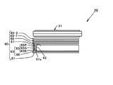
(第2実施形態)次に、第2実施形態では本発明のバックライトユニットについて図8〜図11を用いて説明する。ここで、図8は本発明の第2実施形態に係るバックライトユニットを液晶表示パネルの背面側に備えた表示装置の側面図を示している。また、図9は図8における導光板とLEDを液晶表示パネル側から見た平面図、図10は図9におけるA−A断面図を示している。また、図11はLEDの配置状況を説明する模式的に描いた斜視図を示している。 (Second Embodiment) Next, in the second embodiment, the backlight unit of the present invention will be described with reference to FIGS. Here, FIG. 8 shows a side view of a display device provided with the backlight unit according to the second embodiment of the present invention on the back side of the liquid crystal display panel. 9 is a plan view of the light guide plate and the LED in FIG. 8 as viewed from the liquid crystal display panel side, and FIG. 10 is a cross-sectional view taken along line AA in FIG. FIG. 11 is a perspective view schematically illustrating the LED arrangement state.
図8において、表示装置20は液晶表示パネル21と液晶表示パネル21の背面側に備えたバックライトユニット60からなっている。液晶表示パネル21は一対の上下基板の間に液晶材料を封入し、更に、TFT型の表示画素を複数形成し、その表示画素毎に赤色(R)、緑色(G)、青色(B)のカラーフィルターを設けたアクティブマトリックス型の表示パネルをなしている。また、上下基板の上面及び下面には偏光板を設けている。
In FIG. 8, the
バックライトユニット60は、一番下側から反射シート67、導光板61、拡散シート68、2枚のプリズムシート69−1、69−2を積層し、導光板61の側面に光源ユニット63を配設した構成をなしている。尚図8において、反射シート67、導光板61、拡散シート68、2枚のプリズムシート69−1、69−2はそれぞれ隙間を有しているが、隙間無く積層した構造をなしても構わない。また、光源ユニット63は実装基板66に放射スペクトルの最大波長が赤色領域を示す赤色(R)発光のLED65R、放射スペクトルの最大波長が緑色領域を示す緑色(G)発光のLED65G、放射スペクトルの最大波長が青色領域を示す青色(B)発光のLED65Bの3種類のLED65を実装したものから構成している。この光源ユニット63は導光板61の光の入射面61aに設けた光分散手段62にLED65が対面するように配置している。
The
ここで、バックライトユニット60を構成する各構成部品の仕様について簡単に説明する。反射シート67は樹脂シートにアルミ金属蒸着膜などを設けた反射シートで鏡面のような光沢面をなして反射率が非常に高い反射シートになっている。この反射シート67は導光板61を透過して導光板61から抜けた光を反射させて再び導光板61内に戻す働きをなしている。拡散シート68は透明な樹脂にシリカ微粒子を分散してシートにしたもので、導光板61の出射面61cから出射した光を拡散させる目的で設けている。2枚のプリズムシート69−1、69−2はプリズムが平行に連設されていて、プリズムシート69−1と69−2は同じ仕様をなしているものであるが、プリズムシート69−1のプリズムとプリズムシート69−2のプリズムは直交する配置にして配設している。プリズムシート69−1と69−2を透過する光は垂直光に近い状態になって液晶表示パネルに入射する。このようにプリズムシート69−1と69−2を直交して重ねることにより表示パネルの照明明るさが増す。
Here, the specification of each component which comprises the
導光板61は透明なアクリル樹脂やポリカーボネイト樹脂などで形成され、四角な平板状の形状をなしている。この導光板61はLED65の光を採光する側の側面に入射面61a、その入射面に対向する反対側の側面に対向面61b、拡散シート68と対面する上面側に光を放射する出射面61c、出射面61cと対向する面に下面61dを有している。また、図示はしていないが、この下面61dにはプリズムなどの反射手段が設けられていて、入射面61aから入射した光を出射面61cに反射させる働きをさせている。また、導光板61の入射面61aには半円形なる凹溝の平行列をなした光反射手段62が設けられている。この光反射手段62は前述の第1実施形態で用いた光反射手段と同じ様態をなしており、出射面61cと平行な平行列配置をなしている。
The
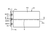
LED65はRのLED65R、GのLED65G、BのLED65Bの3種類のLEDを用いている。これは、R、G、BのLED65を同時に点灯してR、G、Bの混色を図り、白色をなす光を得るためである。R、G、B混色での白色になった光を照射することで液晶表示パネル21のカラー画像に鮮明で明るいカラー色調が現れてくる。また、R、G、BのLED65を使用することで、白色発光のLEDや冷陰極蛍光管の光源では実現困難であった濃い赤色や緑色の色調が得られ、液晶表示パネル21の色再現範囲を拡大する効果が得られる。このR、G、Bの3種類のLED65は、図10の断面図に示すように、導光板61の入射面61aに対面して、厚み方向に3段に積み重ねて配置している。また、この3段に積み重ねたLED65を3組、図9の平面図に示すように、導光板61の幅方向3箇所のZa、Zb、Zc(このZa、Zb、Zcは後述するが、何れも軸を指している)の位置に配置している。尚第2実施形態では、3段に積み重ねたLED65は導光板61の幅方向3箇所に配置しているが、これは、導光板61の幅の大きさ(長さ)やLED65の指向強度特性などによって配置個所は適宜に設定されるものである。
The
ここで、第2実施形態におけるR、G、BのLED65の配置については、図9、図10、図11を用いて更に詳しく説明する。図9〜図11の中で、Xは入射面61aから入射したLEDの光が対向面61bに向かって導波していく方向を指す光導波方向軸としている。図9において、導光板61の幅方向3箇所(Za、Zb、Zc)に設けた3段重ねのLED65の配置は、導光板61の入射面61aの近傍にあって、導光板61の出射面61cと平行で、且つ、光導波方向軸Xと垂直な軸上が選ばれる。出射面61cと平行で、且つ、光導波方向軸Xと垂直な軸を第1の軸とすると、第1の軸は無数に存在し、その中で、入射面61aとの距離や出射面61cとの高さ、LED65の指向強度特性などを考慮して好適な位置の軸が選ばれる。図9において、好適な第1の軸として軸Yaを1つ選択している。この好適な第1の軸Yaは図11の斜視図では一点鎖線のYaの軸を示している。
Here, the arrangement of the R, G, and
次に、この好適な第1の軸Yaと垂直をなして、且つ、第1の軸Yaを中心にして360°の範囲の中で選択した軸を第2の軸とすると、この第2の軸は、導光板61の幅方向の大きさ(長さ)やLED65の指向強度特性、LED65の大きさなどを考慮して好適な第2の軸を選択する。図11において、Za、Zb、Zcの3つの軸を好適な第2の軸として選択している。図9で示した導光板61の幅方向3箇所のZa、Zb、Zcの位置がこの3つの好適な第2の軸Za、Zb、Zcに該当する位置を指している。また、この第2の軸Za、Zb、Zcは、第2実施形態においては、図10、図11に示す如く導光板61の受光面61aと平行をなす軸Za、Zb、Zcを好適な第2の軸として選択している。そして、R、G、BのLED65はこの好適な第2の軸Za、Zb、Zc上に、LEDの発光面中心部がくるように配置している。第2実施形態においては、第2の軸に導光板61の受光面61aと平行をなす軸を選択しているので、R、G、BのLED65は3段に積み重ねて配置した配置形態をなしている。
Next, assuming that the second axis is an axis selected perpendicularly to the preferred first axis Ya and within the range of 360 ° about the first axis Ya, the second axis As the axis, a suitable second axis is selected in consideration of the size (length) of the
第2実施形態において、好適な第2の軸Za、Zb、Zcのそれぞれの軸間はLED65の指向強度特性などを考慮し、また、導光板61の入射面61aに入射する相隣合う組のLEDの光が、入射面61aの極近傍でも、十分に混ざり合うように適宜な距離をなして設定している。また、3段に積み重ねたR、G、BのLED65の重ねる間隔は出来るだけ狭くして配置している。
In the second embodiment, the distance between suitable second axes Za, Zb, Zc is determined in consideration of the directional intensity characteristics of the
R、G、BのLED65の指向範囲は概ね同じ範囲を持っている。そして、好適な第2の軸Za、Zb、Zcのそれぞれの軸間を相隣合う組のLEDの光が十分に混ざり合うように好適な距離を持って設定していることで、導光板61の幅方向においては光の混ざり合いは十分に行われる。次に、3段に重ね合ったR、G、BのLED65の厚み方向の混ざり合いであるが、導光板61の受光面61aに光分散手段62を設けることにより、前述の第1実施形態で詳しく説明した如く、導光板61の受光面61aの極近傍でもR、G、Bの光の混ざり合いが起き、また、導光板61の下面61dに設けてある反射手段や反射シートの作用を受けて、受光面61aの極近傍でもR、G、Bの光の拡散光が多くなり、R、G、Bの混ざり合った多くの光量が受光面61aの極近傍からも出射するようになる。このため、導光板61の広い面積でもって、R、G、Bの十分に混ざり合った光が均一な光量で出射するようになって白色になる面積は大きくなる。
The directivity ranges of the R, G, and
また、導光板61の出射面61c側に拡散シート68が設けられているため、入射面61aの極近傍から出射する光もその拡散シート68により拡散され、R、G、Bの光は更に著しく拡散される。これらのことにより、バックライトユニット60の発光面からはR、G、Bの光が十分混色されての白色になった光が出射されるようになって、バックライトユニットの発光面には色むらは殆ど視認されないようになる。検証の結果では、導光板が14インチサイズのものにR、G、Bの3種類のLEDを3段に配置して、それを75組用いたバックライトユニットは、発光面の中心輝度が3000cd/m2程度、発光面の輝度均一性が80%程度得られ、発光面中央部の混色された白色のxyの色度を基準にして発光面全域のxy色度を測定すると、色度差は±0.01未満の結果が得られた。この色度差は±0.01未満の数値は目視では色むらが視認できない程度のものである。
Further, since the
また、以上のことによって、導光板61の使用できる有効面積、並びに、バックライトユニットの発光面の使用できる面積は広くなる。液晶表示パネル21の画像表示面積が変わらないとするならば、導光板61の大きさ、バックライトユニット60の大きさを画像表示面積に対応した大きさにまで小さくすることができる。即ち、バックライトユニット60の小型化が可能になる。このことは、液晶表示パネル21の大きさは変わらないまでもバックライトユニット60の小型化によって表示装置20も小型にできる効果を生む。
Moreover, the effective area which the light-
尚、第2実施形態においては、光反射手段62を半円形なる凹溝の平行列をなして出射面61cと平行に形成した様態にしたが、この光反射手段62は、前述の第1実施形態で図5の(a)図で示した出射面と傾斜(傾斜角θ)を持った平行列をなした形態、図5の(b)に示した出射面と傾斜をなす平行列をなす光分散手段が2種類あって、その2種類の平行列をなす光分散手段が混ざり合った様態をなしたものでも良い。また、この光反射手段62は、前述の第1実施形態で図6(a)や図6の(b)示した不連続線状の様態をなすものでも構わない。
In the second embodiment, the light reflecting means 62 is formed in parallel with the
(第3実施形態)次に、本発明のバックライトユニットに係る第3実施形態について図12〜図14を用いて説明する。ここで、図12は本発明の第3実施形態に係るバックライトユニットを備えた表示装置の側面図を示している。また、図13は図12における導光板とLEDの配置平面図で、図14は図12における導光板と光源ユニットの要部断面図を示している。 (Third Embodiment) Next, a third embodiment of the backlight unit of the present invention will be described with reference to FIGS. Here, FIG. 12 shows a side view of a display device including a backlight unit according to the third embodiment of the present invention. 13 is an arrangement plan view of the light guide plate and the LED in FIG. 12, and FIG. 14 is a cross-sectional view of the main part of the light guide plate and the light source unit in FIG.
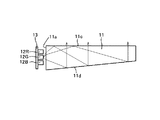
第3実施形態に係る表示装置70は、図12に示すように、液晶表示パネル21の背面側にバックライトユニット80を備えたものからなる。ここでの液晶表示パネル21は前述の第2実施形態で用いた液晶表示パネルと同じ仕様のものを用いている。また、バックライトユニット80は下層側から反射シート87、導光板81、拡散シート88、2枚のプリズムシート89−1、89−2を積層し、導光板81の側面に光源ユニット83を配設した構成をなしている。また、光源ユニット83は、図14に示すように、放射スペクトルの最大波長が赤色領域を示す赤色(R)発光のLED85R、放射スペクトルの最大波長が緑色領域を示す緑色(G)発光のLED85G、放射スペクトルの最大波長が青色領域を示す青色(B)発光のLED85Bの3種類のLED85を実装基板86に実装し、LED85の光放射側に反射部材84を配設した構成をなしている。第3実施形態の光源ユニット83はLED85の光をLED85の真上側に放射し、その放射光を反射部材84でもって反射させて、その反射光を導光板81の入射面81aに入射させる構造を取っている。
As shown in FIG. 12, the
第3実施形態におけるバックライトユニット80を構成する構成部品について簡単に説明する。反射シート87、拡散シート88、2枚のプリズムシート89−1、89−2は前述の第2実施形態で用いた反射シート、拡散シート、2枚のプリズムシートと同じ仕様のものを用いているのでその仕様の説明は省略する。導光板81も前述の第2実施形態の導光板と同じ仕様のものを用いており、入射面81aには半円形なる凹溝の平行列をなした光反射手段82を出射面81cと平行に設けている。尚、厚みは前述の第2実施形態の導光板より薄くなっている。
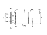
The components constituting the
光源ユニット83のLED85の配置は、図13に示すように、R、G、Bの3種類のLED85を横に並べた状態に配置し、それを列状にして3組配置している。1組目は軸Za上に、2組目は軸Zb上に、3組目は軸Zc上である。
As shown in FIG. 13, the
ここで、図13、図14において、Xは入射面81aから入射したLEDの光が対向面81bに向かって導波していく方向を指す光導波方向軸Xとしている。図13において、導光板81の入射面81aの近傍にあって、導光板81の出射面81cと平行で、且つ、光導波方向軸Xと垂直な軸を第1の軸とすると、第1の軸は無数に有り、その中で、入射面81aとの距離や出射面81cとの高さ、LED85の指向強度特性などを考慮して好適な位置の第1の軸Yaを1つ選択している。また、この好適な第1の軸Yaと垂直をなして、且つ、第1の軸Yaを中心にして360°の範囲の中で選択した軸を第2の軸とすると、この第2の軸は、導光板81の幅方向の大きさ(長さ)やLED85の指向強度特性、LED85の大きさ、相隣り合う組のLEDの光の混ざり合いなどを考慮して好適な第2の軸を選択する。図13において、受光面81aと垂直をなしているZa、Zb、Zcの3つの軸を好適な第2の軸として選択している。そして、この好適な第2の軸Za、Zb、Zc上に、LEDの発光面中心部がくるように適宜な間隔で配置している。
Here, in FIGS. 13 and 14, X is an optical waveguide direction axis X indicating the direction in which the light of the LED incident from the
次に、反射部材84は反射率の高い反射面84aを持った金属薄板や樹脂フィルムなどから形成している。第3実施形態では曲面状のものを用いているが、平板状のものでも良いものである。
Next, the reflecting
第3実施形態のバックライトユニット80は、図14に示すように、R、G、BのLED85から光を反射部材84に向かって同時に出射される。出射光は反射部材84によって反射され、その反射光は導光板81の入射面81aに入射する。そして、入射面81aの光反射手段82によって厚み方向に広角的に分散して導光板81内を進行する。このような構造を取ることにより、入射面81aに入射する入射光は、反射部材84からの反射によってR、G、Bの光がある程度既に混ざり合って入射する。更に、入射面81aの光分散手段82での分散によって混ざり合いが進行することから、入射面81aの極近傍や入射面81a際でもR、G、Bの混ざり合った光の拡散光が多く現れる。そして、これらの拡散光が出射面81cから出射するので、導光板81の出射面81cのほぼ全面からR、G、Bの光が十分に混ざり合って白色をなす光が出射する。また更に、導光板81の出射面81c側に設けた拡散シート88の作用を受けて著しい拡散が行われる。このことにより、バックライトユニットの発光面からはR、G、Bの十分に混ざり合った白色をなした光が出射して、発光面には色むらは現れなくなる。
As shown in FIG. 14, the
更にまた、R、G、BのLED85を平面的に配置していること、反射部材84を介して導光板81に採光していることから、導光板81を薄型にできて、バックライトユニット80の薄型化ができる効果を得る。また、LEDの大きさが厚みの大きいものを使用する場合には、このように平面的に並べる構成を取ると良い。
Furthermore, since the R, G, and
尚、第3実施形態の光源ユニット83は、導光板81の下面81d側の方にR、G、BのLED85を配置し、反射部材84を出射面81c側に配置した構造をなしたが、R、G、BのLED85と反射部材84の配置構造を入れ替えて逆の配置構造をなしても何ら支障はない。
The light source unit 83 of the third embodiment has a structure in which R, G, and
第3実施形態でのR、G、Bの3種類のLED85の配置は第1の軸Yaと垂直をなし、且つ、入射面81aと垂直をなす第2の軸(Za、Zb、Zc)上に配置する配置形態をなした。また、前述の第2実施形態においては、第1の軸Yaと垂直をなし、且つ、入射面と平行をなす第2の軸(Za、Zb、Zc)上に配置する配置形態をなした。しかしながら、本発明はこのような配置に限るものではなく、これ以外の配置形態も取ることができる。ここに、他の配置形態の1例を図15を用いて説明する。図15はR、G、Bの3種類のLEDの他の配置形態をなした側面図を示していて、図15の(a)はR、G、BのLEDを第1の軸を中心にして360°の範囲の中で入射面と傾斜をなした1つの第2の軸上に配置した形態を示し、図15の(b)はR、G、BのLEDを第1の軸を中心にして360°の範囲の中で3つの軸を選択した第2の軸上に配置した形態を示している。尚、導光板の入射面に設ける光分散手段は省略してある。
The arrangement of the three types of
先ず、図15の(a)に示す配置形態は、導光板71の入射面71aの近傍で、好適な第1の軸Yaと垂直で、且つ、第1の軸Yaを中心にして360°の範囲の中で入射面71aと傾斜角θを持つ1つの第2の軸Za上にR、G、BのLEDを配置している。即ち、LEDの光出射面が入射面71aに向かって階段状に配置した配置形態をなしている。LEDの光強度指向特性に応じて入射面71aとの距離を異にして配置でき、強度指向特性を調整する配置として選択できる。ここでの傾斜角θはLEDの光強度指向特性を考慮して適宜に設定すると良い。
First, the arrangement shown in FIG. 15A is in the vicinity of the
次に、図15の(b)に示す配置形態は、導光板71の入射面71aの近傍で、好適な第1の軸Yaと垂直で、且つ、第1の軸Yaを中心にして360°の範囲の中で入射面71aと平行な軸Zaと、入射面71aと傾斜角αを成す軸Zcと、入射面71aと傾斜角βを成す軸Zbの3つの軸を第2の軸として選択している。そして、この3つの第2の軸
Za、Zb、Zc上にLED75G、75B、75Rを配置している。
Next, the arrangement form shown in FIG. 15B is 360 ° in the vicinity of the
他の配置形態として以上2つの例を示したが、この配置形態以外にも色々な配置形態が考えられる。何れも要求される仕様に合った配置形態を取るのが望ましい。 Although two examples have been shown as other arrangement forms, various arrangement forms can be considered in addition to this arrangement form. In any case, it is desirable to adopt an arrangement that meets the required specifications.
(第4実施形態)次に、本発明の第4実施形態に係るバックライトユニットについて図16を用いて説明する。尚、第4実施形態のバックライトユニットは、前述の第2実施形態でのバックライトユニットの構成と比較して光源ユニットのみが異なっているので、光源ユニットを主体にして説明することにし、他の構成部品の説明は必要限度に留めることにする。ここで、図16は本発明の第4実施形態に係るバックライトユニットの光源ユニットと導光板の要部断面図を示している。 (Fourth Embodiment) Next, a backlight unit according to a fourth embodiment of the present invention will be described with reference to FIG. The backlight unit according to the fourth embodiment is different from the backlight unit according to the second embodiment described above only in the light source unit. Therefore, the description will focus on the light source unit. The description of the components will be limited to the necessary limit. Here, FIG. 16 shows a cross-sectional view of main parts of the light source unit and the light guide plate of the backlight unit according to the fourth embodiment of the present invention.
第4実施形態に係る光源ユニット93は実装基板96上に、放射スペクトルの最大波長が赤色領域を示す赤色(R)発光のLED95Rと青色の発光素子に黄色の蛍光体を被覆してパッケージして形成した白色系LED95Byの2種類のLED95を実装したものからなっている。そして、この2種類のLED95は導光板91の入射面91aの近傍にあって、好適な第1の軸Ya(図16において、軸Yaを分かり易くするために誇張して黒点で表示している。この第1の軸Yaは、前述の第2実施形態で述べた如く、導光板91の出射面91cと平行で、且つ、光導波方向軸Xと垂直をなす軸の中で位置的に好適な軸が選ばれている)と垂直をなす好適な第2の軸Za上に2段に積み重ねて配置している。
The
導光板91は、前述の第2実施形態で用いた導光板と同じ仕様のものを用いており、導光板91の入射面91aには厚み方向に光を分散させるために半円形なる凹溝の平行列をなして出射面91cと平行に設けた光分散手段92を有している。
The
ここで、光源ユニット93を構成する白色系LED95Byは、青色発光素子を被覆する透明樹脂の中に黄色(YAG系)の蛍光体を分散させてパッケージしたもので、青色発光素子から発光される青色光に黄色の蛍光体粒子が励起されて発光し、パッケージのLEDからは白色系光が得られるものである。この白色系LED95Byからの白色系光とLED95Rからの赤色光が混ざり合って混色すると赤色領域の発光波長の入った光が得られる。これは、液晶表示パネルにおけるカラー画像の色再現範囲拡大の効果を生む。
Here, the white LED 95By constituting the
尚、第4実施形態では、蛍光体に黄色の蛍光体を用いたが、黄色の蛍光体に限るものではなく、緑色系蛍光体などを用いても良い。緑色系蛍光体としては、例えば、リン酸塩系、ケイ酸塩系、アルミン酸塩系の蛍光体などがある。 In the fourth embodiment, the yellow phosphor is used as the phosphor. However, the phosphor is not limited to the yellow phosphor, and a green phosphor or the like may be used. Examples of green phosphors include phosphate, silicate, and aluminate phosphors.
以上の構成をなすことにより、用いるLEDは2種類で良いので、それに合わせて導光板91の厚み(T)を薄くできる効果、光源ユニット93の組立工数の削減効果なども得られる。また、当然ながら、前述の第2実施形態と同様に、色むらの発生防止効果を得るものである。また、用途によっては別な発色の光源を用いて、その組合せで他の色の混色を得ることも可能である。
By using the above configuration, two types of LEDs may be used, and accordingly, the effect of reducing the thickness (T) of the
(第5実施形態)次に、本発明の第5実施形態に係るバックライトユニットについて図17を用いて説明する。第5実施形態のバックライトユニットは、前述の第2実施形態でのバックライトユニットの構成と比較して導光板の仕様のみが異なっている。従って、導光板を主体にして説明することにし、他の構成部品の説明は必要限度に留めることにする。また、第2実施形態での構成部品と同じ仕様を成す構成部品は同一符号を付して説明する。ここで、図17は本発明の第5実施形態に係るバックライトユニットの光源ユニットと導光板の要部断面図を示している。 (Fifth Embodiment) Next, a backlight unit according to a fifth embodiment of the present invention will be described with reference to FIG. The backlight unit of the fifth embodiment is different only in the specification of the light guide plate compared to the configuration of the backlight unit in the second embodiment described above. Accordingly, the description will be made with the light guide plate as the main component, and the description of other components will be limited to the necessary limit. In addition, components having the same specifications as the components in the second embodiment will be described with the same reference numerals. Here, FIG. 17 shows a cross-sectional view of main parts of the light source unit and the light guide plate of the backlight unit according to the fifth embodiment of the present invention.
第5実施形態での導光板101は3つの分割導光板101A、101B、101C
を3段に積み重ねて構成している。そして、分割導光板101A、101B、101Cの各々は、赤色発光のLED65R、緑色発光のLED65G、青色発光のLED65Bと対面して配置している。また、分割導光板101A、101B、101Cのそれぞれは、それぞれの入射面101Aa、101Ba、101Caに光分散手段102を設けている。この光分散手段102は半円形なる凹溝の平行列をなした様態のもので、前述の第2実施形態での光分散手段と同じ様態をなしている。また、図示はしていないが、分割導光板101A、101B、101Cのそれぞれの下面101Ad、101Bd、101Cdには、それぞれプリズムなどの凹凸のある反射手段が設けている。
The
Are stacked in three stages. Each of the divided
光源ユニット63は、前述の第2実施形態での構成と同じ構成をなしており、R、G、BのLED65を3段に積み重ねたようにして配置している。
The
バックライトユニットに以上の構成の導光板101を用いることにより、LED65の種類の数に対応して分割導光板の積み重ねる数を設定することができる。また、この分割導光板は、例えば、白色LED用の導光板に横溝なる光分散手段を追加することによって流用して使用することができる。この場合、金型の一部の金型部品を入れ替え交換することによって導光板の製作が可能になる。例えば、光分散手段の仕様を設けた金型の入れ子部品を入れ替えることによって達成できる。このような構成を取ると、金型費用は安く上がり、金型費用の削減効果が得られる。また、前述の第4実施形態での白色系LEDと赤色(R)発光のLEDの2種類を用いた光源ユニットの場合は2個の分割導光板を重ねることによって所望の導光板が得られることになる。
By using the
また更に、分割導光板101A、101B、101Cを重ね合わせた合わせ目には、分割導光板101A、101B、101Cのそれぞれの下面101Ad、101Bd、101Cdにプリズムなどの凹凸のある反射手段を設けてあることより空気層が存在する。この空気層は光を屈折させる働きをすることから、分割導光板を透過する光に屈折が起き、光の拡散が更に生まれてくる。このことは、R、G、BのLED65の混色を促進すると共に、色むらの発生防止効果を高める方向に作用する。
Furthermore, in the joint where the divided
(第6実施形態)次に、本発明の第6実施形態に係るバックライトユニットについて図18を用いて説明する。第6実施形態のバックライトユニットは、前述の第2実施形態でのバックライトユニットの構成と比較して光源ユニットの仕様のみが異なっている。従って、光源ユニットを主体にして説明することにし、他の構成部品の説明は必要限度に留めることにする。また、第2実施形態での構成部品と同じ仕様を成す構成部品は同一符号を付して説明する。ここで、図18は本発明の第6実施形態に係るバックライトユニットの光源ユニットと導光板の要部断面図を示している。 (Sixth Embodiment) Next, a backlight unit according to a sixth embodiment of the present invention will be described with reference to FIG. The backlight unit according to the sixth embodiment is different from the backlight unit according to the second embodiment only in the specification of the light source unit. Therefore, the description will be made mainly with the light source unit, and description of other components will be limited to the necessary limit. In addition, components having the same specifications as the components in the second embodiment will be described with the same reference numerals. Here, FIG. 18 shows a cross-sectional view of main parts of the light source unit and the light guide plate of the backlight unit according to the sixth embodiment of the present invention.
第6実施形態での光源ユニット113は、図18に示すように、赤色発光のLED115Rは実装基板116aに実装し、緑色発光のLED115Gは実装基板116bに実装し、青色発光のLED115Bは実装基板116cに実装している。即ち、3種類のLED115R、115G、115Bはそれぞれ別個の実装基板に実装している。3段に重ね合ったR、G、BのLEDの組が複数組、導光板61の入射面61aの近傍に配置された場合に、一番上段のLEDは1つの実装基板に、中段のLEDは1つの実装基板に、下段のLEDは1つの実装基板に実装する形態を取る。そして、実装基板付きで3段に積み重ねて光源ユニットを構成している。ここでのLEDは側面発光型のLEDを用いている。
In the
LEDが薄型の場合には側面発光型のLEDを用いて図18に示す光源ユニットを構成すると良い。今まで説明してきた第2実施形態から第5実施形態での光源ユニットは、R、G、BのLEDを1つの実装基板に幅方向に並べて配置した実装形態をなしたものである。LEDの幅などが大きいと実装基板の幅も広いものを使用しなければならない。しかしながら、実装基板の幅が大きいと狭いスペースの中での収納配置の問題が現れる。第6実施形態での光源ユニット113の構成は上記の問題を解決する構成になっている。R、G、BのLEDが厚みが薄い場合は、それぞれに幅の狭い実装基板を用いて、上記した如く、上段のLEDを1つの実装基板に、中段のLEDを1つの実装基板に、下段のLEDを1つの実装基板に実装し、導光板61の受光面61aの近傍に積み重ねて配置する方法を取ることにより狭い収納スペースでも収納できる。また、このような構成を取ると、LEDが受光面61aの中央部にかたまって配置されることになってより良い混色が得られるようになる。
When the LED is thin, the light source unit shown in FIG. 18 may be configured using a side-emitting LED. The light source units in the second to fifth embodiments described so far have a mounting form in which R, G, and B LEDs are arranged side by side in the width direction on one mounting board. When the width of the LED is large, a mounting substrate having a large width must be used. However, if the width of the mounting substrate is large, the problem of storage arrangement in a narrow space appears. The configuration of the
(第7実施形態)次に、本発明の第7実施形態に係るバックライトユニットについて図19〜図21を用いて説明する。第7実施形態のバックライトユニットは、前述の第2実施形態でのバックライトユニットの構成と比較して導光板の仕様のみが異なっている。従って、導光板を主体に説明することにし、他の構成部品の説明は必要限度に留めることにする。また、第2実施形態での構成部品と同じ仕様を成す構成部品は同一符号を付して説明する。ここで、図19は本発明の第7実施形態に係るバックライトユニットの導光板の斜視図を示していて、図20は図19における導光板と光源ユニットの配置を示す平面図、図21は図20における光源ユニットと導光板の要部断面図を示している。 (Seventh Embodiment) Next, a backlight unit according to a seventh embodiment of the present invention will be described with reference to FIGS. The backlight unit according to the seventh embodiment is different from the backlight unit according to the second embodiment only in the specification of the light guide plate. Accordingly, the description will be made mainly with respect to the light guide plate, and description of other components will be limited to the necessary limit. In addition, components having the same specifications as the components in the second embodiment will be described with the same reference numerals. Here, FIG. 19 is a perspective view of the light guide plate of the backlight unit according to the seventh embodiment of the present invention, FIG. 20 is a plan view showing the arrangement of the light guide plate and the light source unit in FIG. 19, and FIG. The principal part sectional drawing of the light source unit and light-guide plate in FIG. 20 is shown.
第7実施形態に係る導光板121は、図19に示すように、導光板121の入射面121aに2種類の光分散手段を設けている。1つの種類の光分散手段は、導光板121の厚み(T)方向に光を分散させるために設ける半円形の凹溝で、これは、出射面121cと平行で筋状に平行列をなした第1の光分散手段122aである。もう一つの種類の光分散手段は、導光板121の幅(W)方向に光を分散させるために設ける半円形の凹溝で、これは、出射面121cと垂直で筋状に縦に平行列をなして設けた第2の光分散手段122bである。第1の光分散手段122a及び第2の光分散手段122bは何れも溝幅が数μm〜数10μmのものであるが、図19においては分かり易くするために大きく誇張して描いてある。第1の光分散手段122aでLEDの光を厚み方向に分散させ、第2の光分散手段122でLEDの光を幅方向に分散させる。
As shown in FIG. 19, the
第7実施形態での光源ユニット63は、図21に示すように、実装基板66にR、G、BのLED65を実装したものからなるが、この光源ユニット63は、図20に示すように、3組が導光板121の入射面121aに対面して、適宜な間隔を持って好適な第2の軸Za、Zb、Zc上に配置されている。この好適な第2の軸Za、Zb、Zcは、出射面121cと平行で、且つ、光導波方向軸と垂直をなす好適な第1の軸Yaと垂直をなしており、また、図21に示すように入射面121aと平行をなしている。この好適な第2の軸Za、Zb、Zcや好適な第1の軸Yaに関しては前述の第2実施形態で説明した内容の通りである。
The
導光板121の入射面121aに設けている厚み方向に光を分散させる第1の光分散手段122aは、今までの実施形態の中で説明したように、3段に積み重ねたR、G、Bの光を広角的に分散させ、入射面121aの極近傍でも混色させる働きをなす。一方、幅方向に光を分散させる第2の光分散手段122bは、3組のLED65の光を幅方向に広角的に分散させ、相隣り合うLEDの光を入射面121aの極近傍でも混色させる働きをなす。このように、厚み方向の光分散手段と幅方向の光分散手段の両方を設けることにより、入射面121aの極近傍でもR、G、Bの混色が十分に行われて、色むらの発生を無くすことができる。
The first light dispersion means 122a that disperses the light in the thickness direction provided on the
以上、第1実施形態から第7実施形態に渡って本発明の導光板とバックライトユニット、並びに表示装置について説明を行った。何れも、R、G、Bの光を混色させて色むらの無い白色の光を得、カラーフィルターを設けた表示装置のカラー画像に色むらをなくして、色再現範囲を拡大するものであった。本発明の導光板とバックライトユニットは、カラーフィルターを設けた表示装置に限らず、フィールドシーケンシャルカラー方式の表示装置にも効果的に適用できるものである。R、G、BのLEDを高速で順次点灯し、この点灯と同期させて液晶表示パネルの関係する画像表示画素を開口することにより、R、G、Bの発光色でのカラー画像が得られる。フィールドシーケンシャルカラー方式の表示装置に本発明の導光板でバックライトユニットを構成すると、バックライトユニットの発光面の全域からはR、G、Bの光が、それぞれ均一な光量をなして出射するので、カラー画像の色調に色むらが現れない。そして、あらゆる色調をなすカラー画像が得られるようになる。また、本発明のバックライトユニットはプロジェクター(画像投影機)にも利用することができる。本発明のバックライトユニットを用いて、バックライトユニットからの放射する光で液晶表示パネルの表示画像を投影する構成を取ると、投影カラー画像に色むらが現れない。また、投影カラー画像に濃い赤色や緑色の色調も得られて色再現範囲も拡大される。 The light guide plate, the backlight unit, and the display device of the present invention have been described above from the first embodiment to the seventh embodiment. In either case, R, G, and B light are mixed to obtain white light with no color unevenness, color unevenness is eliminated from the color image of the display device provided with the color filter, and the color reproduction range is expanded. It was. The light guide plate and the backlight unit of the present invention can be effectively applied not only to a display device provided with a color filter but also to a field sequential color display device. The R, G, and B LEDs are sequentially turned on at high speed sequentially, and the image display pixels related to the liquid crystal display panel are opened in synchronization with the lighting, thereby obtaining a color image in the R, G, and B emission colors. . When a backlight unit is configured with the light guide plate of the present invention in a field sequential color display device, R, G, and B light are emitted from the entire area of the light emitting surface of the backlight unit with uniform amounts of light. Color unevenness does not appear in the color tone of the color image. Then, a color image having any color tone can be obtained. The backlight unit of the present invention can also be used for a projector (image projector). If the backlight unit of the present invention is used to project the display image of the liquid crystal display panel with the light emitted from the backlight unit, uneven color does not appear in the projected color image. In addition, dark red and green colors are obtained in the projected color image, and the color reproduction range is expanded.
20、70 表示装置
21 液晶表示パネル
31、41、51、61、71、81、91、101、121 導光板
31a、41a、51a、61a、71a、81a、91a、101Aa、101Ba、101Ca、121a 入射面
31b、61b、81b、91b 対向面
31c、41c、51c、61c、81c、91c、101Ac、121c 出射面
31d、41d、51d、61d、81d、91d、101Ad、101Bd、101Cd、121d 下面
32、62、82、92、102 光分散手段
35、65、85、95 LED
35R、65R、75R、85R、95R、115R 赤色発光のLED
35G、65G、75G、85G、115G 緑色発光のLED
35B、65B、75B、85B、115B 青色発光のLED
95By 白色系LED
60、80 バックライトユニット
63、83、93、113 光源ユニット
66、86、96、116a、116b、116c 実装基板
67、87 反射シート
68、88 拡散シート
69−1、69−2、89−1、89−2 プリズムシート
84 反射部材
101A、101B、101C 分割導光板
122a 第1の光分散手段
122b 第2の光分散手段
X 光導波方向軸
Ya、Yb 第1の軸
Za、Zb、Zc 第2の軸
20, 70
35R, 65R, 75R, 85R, 95R, 115R Red LED
35G, 65G, 75G, 85G, 115G Green LED
35B, 65B, 75B, 85B, 115B Blue LED
95By white LED
60, 80
Claims (15)
15. A display device comprising a backlight unit on the back side of a liquid crystal display panel, wherein the backlight unit uses the backlight unit according to any one of claims 8 to 14.
Priority Applications (3)
| Application Number | Priority Date | Filing Date | Title |
|---|---|---|---|
| JP2006179002A JP2008010291A (en) | 2006-06-29 | 2006-06-29 | Light guide plate, back light unit, and display device equipped with its back light unit |
| DE102007029659A DE102007029659A1 (en) | 2006-06-29 | 2007-06-27 | Backlight unit and display device with the backlight unit |
| US11/824,294 US20080002429A1 (en) | 2006-06-29 | 2007-06-28 | Backlight unit and display device with the backlight unit |
Applications Claiming Priority (1)
| Application Number | Priority Date | Filing Date | Title |
|---|---|---|---|
| JP2006179002A JP2008010291A (en) | 2006-06-29 | 2006-06-29 | Light guide plate, back light unit, and display device equipped with its back light unit |
Publications (2)
| Publication Number | Publication Date |
|---|---|
| JP2008010291A true JP2008010291A (en) | 2008-01-17 |
| JP2008010291A5 JP2008010291A5 (en) | 2009-07-02 |
Family
ID=38825452
Family Applications (1)
| Application Number | Title | Priority Date | Filing Date |
|---|---|---|---|
| JP2006179002A Pending JP2008010291A (en) | 2006-06-29 | 2006-06-29 | Light guide plate, back light unit, and display device equipped with its back light unit |
Country Status (3)
| Country | Link |
|---|---|
| US (1) | US20080002429A1 (en) |
| JP (1) | JP2008010291A (en) |
| DE (1) | DE102007029659A1 (en) |
Cited By (14)
| Publication number | Priority date | Publication date | Assignee | Title |
|---|---|---|---|---|
| WO2010050489A1 (en) * | 2008-10-30 | 2010-05-06 | 日本ゼオン株式会社 | Light source device and liquid cristal display device |
| JP2010232529A (en) * | 2009-03-27 | 2010-10-14 | Toyoda Gosei Co Ltd | Light emitting device, and backlight device |
| US8199281B2 (en) | 2008-12-29 | 2012-06-12 | Funai Electric Co., Ltd. | Backlight of liquid crystal display device |
| JP2012249208A (en) * | 2011-05-31 | 2012-12-13 | Kyocera Document Solutions Inc | Image reading apparatus and image forming apparatus provided with the same |
| JP2013214378A (en) * | 2012-03-31 | 2013-10-17 | Dainippon Printing Co Ltd | Light guide plate, surface light source device, and display device |
| TWI474085B (en) * | 2011-02-15 | 2015-02-21 | Mitsubishi Electric Corp | Surface light source device and liquid crystal display device |
| TWI489159B (en) * | 2013-10-30 | 2015-06-21 | Wistron Corp | Light guide plate |
| WO2016002883A1 (en) * | 2014-07-03 | 2016-01-07 | シャープ株式会社 | Illumination device and display device |
| JPWO2014199563A1 (en) * | 2013-06-11 | 2017-02-23 | 株式会社小糸製作所 | Vehicle lighting |
| JP2017091931A (en) * | 2015-11-13 | 2017-05-25 | オムロン株式会社 | Surface light source device |
| JP2017091932A (en) * | 2015-11-13 | 2017-05-25 | オムロン株式会社 | Surface light source device, display device and electronic equipment |
| US10488574B2 (en) | 2014-09-05 | 2019-11-26 | Japan Display Inc. | Display device and light source device |
| JP2020525968A (en) * | 2018-05-31 | 2020-08-27 | ハスコ ビジョン テクノロジー カンパニー リミテッド | Surface emitting module of LED light source, vehicle lamp to which the same is applied, and assembling method |
| US11333816B2 (en) | 2017-05-31 | 2022-05-17 | Lumileds Llc | Shaping input surfaces of LED light-guides for increased light extraction efficiency |
Families Citing this family (13)
| Publication number | Priority date | Publication date | Assignee | Title |
|---|---|---|---|---|
| JP2009128647A (en) * | 2007-11-26 | 2009-06-11 | Hitachi Displays Ltd | Liquid crystal display device |
| JP4774035B2 (en) * | 2007-12-28 | 2011-09-14 | シャープ株式会社 | Surface light source and display device |
| TWI418861B (en) * | 2010-03-16 | 2013-12-11 | Coretronic Nanjing Ltd | Light guide plate and backlight module using the same |
| CN102081189A (en) * | 2011-02-22 | 2011-06-01 | 苏州茂立光电科技有限公司 | Light guide plate, illuminating device and manufacturing method of light guide plate |
| US9324250B2 (en) | 2011-09-09 | 2016-04-26 | Dolby Laboratories Licensing Corporation | High dynamic range displays comprising MEMS/IMOD components |
| CN103217733A (en) * | 2012-01-19 | 2013-07-24 | 扬昕科技(苏州)有限公司 | Light guide plate and backlight module |
| CN202708988U (en) * | 2012-07-03 | 2013-01-30 | 深圳安嵘光电产品有限公司 | Light guide plate (LGP) and lighting lamp |
| DE102012108855A1 (en) | 2012-09-20 | 2014-03-20 | Hella Kgaa Hueck & Co. | Optical fiber for vehicles |
| JP5937032B2 (en) * | 2013-03-21 | 2016-06-22 | 株式会社東海理化電機製作所 | Display device |
| CN104459867A (en) * | 2013-09-23 | 2015-03-25 | 纬创资通股份有限公司 | Light guide plate and backlight module |
| US10151441B2 (en) | 2014-10-08 | 2018-12-11 | Koito Manufacturing Co., Ltd. | Light emitting device and vehicle lamp |
| DE102019124073A1 (en) * | 2019-09-09 | 2021-03-11 | Lisa Dräxlmaier GmbH | LIGHTING DEVICE WITH LIGHT GUIDE AS WELL AS VEHICLE AND PROCEDURE |
| FR3139060A1 (en) * | 2022-08-29 | 2024-03-01 | Psa Automobiles Sa | Optical block with photon diffusion not perpendicular to the light guide entrance |
Citations (5)
| Publication number | Priority date | Publication date | Assignee | Title |
|---|---|---|---|---|
| JPH09230342A (en) * | 1996-02-27 | 1997-09-05 | Rohm Co Ltd | Surface light emission illuminating device |
| JP2002196151A (en) * | 2000-12-25 | 2002-07-10 | Citizen Electronics Co Ltd | Light guide plate |
| JP2004078015A (en) * | 2002-08-21 | 2004-03-11 | Nippon Leiz Co Ltd | Light guide plate and planar illumination system |
| JP2005129271A (en) * | 2002-11-29 | 2005-05-19 | Fujitsu Ltd | Reflector, illumination device, light guide plate, and display device |
| JP2005285702A (en) * | 2004-03-31 | 2005-10-13 | Citizen Watch Co Ltd | Translucent member and lighting system using it |
Family Cites Families (3)
| Publication number | Priority date | Publication date | Assignee | Title |
|---|---|---|---|---|
| JP3213496B2 (en) * | 1994-11-30 | 2001-10-02 | シャープ株式会社 | Lighting equipment |
| US20030184990A1 (en) * | 2002-03-26 | 2003-10-02 | Chia-Feng Lin | Light-guiding plate module of high reliability |
| JP3923867B2 (en) * | 2002-07-26 | 2007-06-06 | 株式会社アドバンスト・ディスプレイ | Planar light source device and liquid crystal display device using the same |
-
2006
- 2006-06-29 JP JP2006179002A patent/JP2008010291A/en active Pending
-
2007
- 2007-06-27 DE DE102007029659A patent/DE102007029659A1/en not_active Withdrawn
- 2007-06-28 US US11/824,294 patent/US20080002429A1/en not_active Abandoned
Patent Citations (5)
| Publication number | Priority date | Publication date | Assignee | Title |
|---|---|---|---|---|
| JPH09230342A (en) * | 1996-02-27 | 1997-09-05 | Rohm Co Ltd | Surface light emission illuminating device |
| JP2002196151A (en) * | 2000-12-25 | 2002-07-10 | Citizen Electronics Co Ltd | Light guide plate |
| JP2004078015A (en) * | 2002-08-21 | 2004-03-11 | Nippon Leiz Co Ltd | Light guide plate and planar illumination system |
| JP2005129271A (en) * | 2002-11-29 | 2005-05-19 | Fujitsu Ltd | Reflector, illumination device, light guide plate, and display device |
| JP2005285702A (en) * | 2004-03-31 | 2005-10-13 | Citizen Watch Co Ltd | Translucent member and lighting system using it |
Cited By (15)
| Publication number | Priority date | Publication date | Assignee | Title |
|---|---|---|---|---|
| WO2010050489A1 (en) * | 2008-10-30 | 2010-05-06 | 日本ゼオン株式会社 | Light source device and liquid cristal display device |
| US8199281B2 (en) | 2008-12-29 | 2012-06-12 | Funai Electric Co., Ltd. | Backlight of liquid crystal display device |
| JP2010232529A (en) * | 2009-03-27 | 2010-10-14 | Toyoda Gosei Co Ltd | Light emitting device, and backlight device |
| TWI474085B (en) * | 2011-02-15 | 2015-02-21 | Mitsubishi Electric Corp | Surface light source device and liquid crystal display device |
| US9007627B2 (en) | 2011-05-31 | 2015-04-14 | Kyocera Document Solutions Inc. | Image reading apparatus and image forming apparatus |
| JP2012249208A (en) * | 2011-05-31 | 2012-12-13 | Kyocera Document Solutions Inc | Image reading apparatus and image forming apparatus provided with the same |
| JP2013214378A (en) * | 2012-03-31 | 2013-10-17 | Dainippon Printing Co Ltd | Light guide plate, surface light source device, and display device |
| JPWO2014199563A1 (en) * | 2013-06-11 | 2017-02-23 | 株式会社小糸製作所 | Vehicle lighting |
| TWI489159B (en) * | 2013-10-30 | 2015-06-21 | Wistron Corp | Light guide plate |
| WO2016002883A1 (en) * | 2014-07-03 | 2016-01-07 | シャープ株式会社 | Illumination device and display device |
| US10488574B2 (en) | 2014-09-05 | 2019-11-26 | Japan Display Inc. | Display device and light source device |
| JP2017091931A (en) * | 2015-11-13 | 2017-05-25 | オムロン株式会社 | Surface light source device |
| JP2017091932A (en) * | 2015-11-13 | 2017-05-25 | オムロン株式会社 | Surface light source device, display device and electronic equipment |
| US11333816B2 (en) | 2017-05-31 | 2022-05-17 | Lumileds Llc | Shaping input surfaces of LED light-guides for increased light extraction efficiency |
| JP2020525968A (en) * | 2018-05-31 | 2020-08-27 | ハスコ ビジョン テクノロジー カンパニー リミテッド | Surface emitting module of LED light source, vehicle lamp to which the same is applied, and assembling method |
Also Published As
| Publication number | Publication date |
|---|---|
| DE102007029659A1 (en) | 2008-01-17 |
| US20080002429A1 (en) | 2008-01-03 |
Similar Documents
| Publication | Publication Date | Title |
|---|---|---|
| JP2008010291A (en) | Light guide plate, back light unit, and display device equipped with its back light unit | |
| JP2008010291A5 (en) | ||
| US7635200B2 (en) | Planar light source device and display using the same | |
| US7246931B2 (en) | LED light source | |
| JP4717494B2 (en) | LIGHTING DEVICE AND DISPLAY DEVICE USING THE SAME | |
| US7686495B2 (en) | Light source unit, backlight unit and display apparatus having the same | |
| EP2235589B1 (en) | Illumination system, luminaire and backlighting unit | |
| US7905613B2 (en) | LED backlight and liquid crystal display device using thereof | |
| JP4442767B2 (en) | Light guide plate, surface light source device including the light guide plate, and display device including the surface light source device | |
| JP2010108919A (en) | Planar light source device, and display using the same | |
| KR20130094856A (en) | Surface light source device and liquid crystal display device | |
| JP2006093104A (en) | Lighting system, and display device using the same | |
| JP2006351522A (en) | Back light and liquid crystal display device | |
| KR20080042023A (en) | Surface light source device and display | |
| JP4773410B2 (en) | Light guide plate, surface light source device, and liquid crystal display device | |
| US8462293B2 (en) | Illuminating device and liquid crystal display device | |
| JP2010108948A (en) | Lighting device, and display using the same | |
| JP2005332719A (en) | Planar light source device and display device having planar light source device | |
| CN110632698A (en) | Illumination device and display device | |
| JP2005228535A (en) | Planar light source device and liquid crystal display | |
| JP6406220B2 (en) | Surface light source device, display device, and electronic device | |
| JP2009251122A (en) | Light guide plate and backlight device | |
| TWI399590B (en) | Liquid crystal display, backlight module thereof and light guide structure thereof | |
| JP2010287556A (en) | Lighting device and display including the same | |
| JP2009099270A (en) | Hollow surface lighting device |
Legal Events
| Date | Code | Title | Description |
|---|---|---|---|
| A521 | Request for written amendment filed |
Free format text: JAPANESE INTERMEDIATE CODE: A523 Effective date: 20071206 |
|
| A521 | Request for written amendment filed |
Free format text: JAPANESE INTERMEDIATE CODE: A523 Effective date: 20090515 |
|
| A621 | Written request for application examination |
Free format text: JAPANESE INTERMEDIATE CODE: A621 Effective date: 20090515 |
|
| A977 | Report on retrieval |
Free format text: JAPANESE INTERMEDIATE CODE: A971007 Effective date: 20101112 |
|
| A131 | Notification of reasons for refusal |
Free format text: JAPANESE INTERMEDIATE CODE: A131 Effective date: 20101130 |
|
| A521 | Request for written amendment filed |
Free format text: JAPANESE INTERMEDIATE CODE: A523 Effective date: 20110128 |
|
| A131 | Notification of reasons for refusal |
Free format text: JAPANESE INTERMEDIATE CODE: A131 Effective date: 20110517 |
|
| A02 | Decision of refusal |
Free format text: JAPANESE INTERMEDIATE CODE: A02 Effective date: 20110921 |