WO2012111177A1 - Method for producing instant noodles - Google Patents
Method for producing instant noodles Download PDFInfo
- Publication number
- WO2012111177A1 WO2012111177A1 PCT/JP2011/059993 JP2011059993W WO2012111177A1 WO 2012111177 A1 WO2012111177 A1 WO 2012111177A1 JP 2011059993 W JP2011059993 W JP 2011059993W WO 2012111177 A1 WO2012111177 A1 WO 2012111177A1
- Authority
- WO
- WIPO (PCT)
- Prior art keywords
- noodle
- noodle strings
- airflow
- supply means
- strings
- Prior art date
Links
- LBZDYJMTZFZUIE-VOTSOKGWSA-N CC/C(/C)=N/CC Chemical compound CC/C(/C)=N/CC LBZDYJMTZFZUIE-VOTSOKGWSA-N 0.000 description 1
Images

Classifications
-
- A—HUMAN NECESSITIES
- A23—FOODS OR FOODSTUFFS; TREATMENT THEREOF, NOT COVERED BY OTHER CLASSES
- A23L—FOODS, FOODSTUFFS, OR NON-ALCOHOLIC BEVERAGES, NOT COVERED BY SUBCLASSES A21D OR A23B-A23J; THEIR PREPARATION OR TREATMENT, e.g. COOKING, MODIFICATION OF NUTRITIVE QUALITIES, PHYSICAL TREATMENT; PRESERVATION OF FOODS OR FOODSTUFFS, IN GENERAL
- A23L5/00—Preparation or treatment of foods or foodstuffs, in general; Food or foodstuffs obtained thereby; Materials therefor
- A23L5/10—General methods of cooking foods, e.g. by roasting or frying
- A23L5/13—General methods of cooking foods, e.g. by roasting or frying using water or steam
-
- A—HUMAN NECESSITIES
- A21—BAKING; EDIBLE DOUGHS
- A21C—MACHINES OR EQUIPMENT FOR MAKING OR PROCESSING DOUGHS; HANDLING BAKED ARTICLES MADE FROM DOUGH
- A21C11/00—Other machines for forming the dough into its final shape before cooking or baking
- A21C11/24—Apparatus for cutting out noodles from a sheet or ribbon of dough by an engaging pair of grooved rollers
-
- A—HUMAN NECESSITIES
- A23—FOODS OR FOODSTUFFS; TREATMENT THEREOF, NOT COVERED BY OTHER CLASSES
- A23L—FOODS, FOODSTUFFS, OR NON-ALCOHOLIC BEVERAGES, NOT COVERED BY SUBCLASSES A21D OR A23B-A23J; THEIR PREPARATION OR TREATMENT, e.g. COOKING, MODIFICATION OF NUTRITIVE QUALITIES, PHYSICAL TREATMENT; PRESERVATION OF FOODS OR FOODSTUFFS, IN GENERAL
- A23L7/00—Cereal-derived products; Malt products; Preparation or treatment thereof
- A23L7/10—Cereal-derived products
- A23L7/109—Types of pasta, e.g. macaroni or noodles
- A23L7/113—Parboiled or instant pasta
Definitions
- the present invention relates to a method of manufacturing “substantially straight” instant noodles in which “longitudinal wave” waves are suppressed as much as possible. More specifically, the present invention relates to a method for producing instant noodles, in which waves can be suppressed as much as possible in the noodle strings at the time of eating, and instant noodles that are easily loosened at the time of eating can be easily obtained.
- a method for producing instant noodles wheat flour and various starches are used as raw materials.
- Chinese noodles use kansui
- Japanese-style noodles use polymerized phosphates instead of kansui.
- Salt, powdered eggs, thickening polysaccharides, fats and oils, lecithin, and the like are added and kneaded to prepare noodles in a conventional manner.
- fried noodles and non-fried noodles that is, non-fried noodles are obtained by a predetermined drying method.
- drying methods such as hot air drying, microwave drying, freeze drying, and cold drying are conceivable.
- a dough obtained by kneading noodle raw materials and water is rolled into a sheet to obtain a noodle strip, and then a noodle strip having a predetermined thickness. Is cut out with a noodle cutting device to obtain a noodle string.
- the noodle strings are made alpha in the subsequent steaming process, the flour that is the main ingredient and the added starch are gelatinized and eluted on the surface of the noodle strings, so that the overlapping noodle strings stick to each other. In order to prevent this, the noodle strings are waved.
- the speed of the wave conveyor provided at the lower part of the cutting blade device is made slower than the speed of the noodle wire cut out from the cutting blade, so Constantly clogs and bends inside the conduit, resulting in a uniform wave of noodle strings.
- the “wave” of the noodle strings is generally a wave in the traveling direction of the noodle strings cut by the cutting blade device (that is, the longitudinal direction of the noodle strings). , Sometimes referred to as "longitudinal wave").
- the noodle strings become so-called “crimped noodles”, so that the appearance is not suitable for curly noodles (for example, udon, soba, pasta, Etc.).
- Patent Document 1 discloses a method for producing instant noodles without forming a wave on the noodle strings.
- This method is a manufacturing method in which a boil treatment is performed instead of a steaming step.
- a boil treatment is performed instead of a steaming step.
- Japanese Patent Application Laid-Open No. 2000-189089 is characterized by dissolving salt in boiling water and setting the salt concentration to 20% or more, thereby preventing the dissolution of starch on the surface of the noodle strings and solving the problem of loosening. is there.
- boiling eliminates wave formation, and by dissolving salt in boiling water and making the salt concentration 20% or more, it is possible to make loose noodles that are easy to loosen.
- the investment in the line equipment is large, and the salt concentration is too high, so that the noodles are drunk in the meal.
- Patent Document 2 Japanese Patent Application Laid-Open No. 2010-187623
- Patent Document 2 Japanese Patent Application Laid-Open No. 2010-187623
- the location where the noodle strings are peeled off can be greatly shifted by largely changing the scraping location of the cutting blade between the upper cutting blade roll and the lower cutting blade roll.
- this method does not synchronize the cut raw noodle strings even without applying strong waves to the noodle strings.
- a noodle string in which the binding between the noodle strings is suppressed can be obtained.
- JP 2010-187623 A prevents the synchronization of adjacent noodle strings (that is, the adjacent noodle strings perform the same “movement”) by changing the position where the adjacent noodle strings are peeled off. I can do it.
- noodle string rowing that is, attaching a “partition plate” for rowing to the noodle string cutting blade device.
- the cutting blade device of 2010-187623 has a problem that it is more difficult to perform the above-mentioned “row separation” because the arrangement location of the scraping member of the cutting blade device is complicated.
- An object of the present invention is to provide a method capable of stably producing noodle strings that are “substantially straight” in shape and that have good “fraying” for eating.
- Another object of the present invention is to provide a method capable of stably producing “substantially straight” noodle strings even in a mass production line.
- the instant dry noodle manufacturing method of the present invention is based on the above knowledge, and more specifically, using a rotary cutting device including at least a pair of cutting blade rolls, a scraping member, and an airflow supply means, A method for producing a noodle string, which is cut into noodle strings, Passing the noodle strip through the cutting blade roll and cutting the noodle strip into a noodle strand; Peeling the noodle strings from the cutting blade roll with a scraping member and separating the noodle strings into upper and lower noodle string bundles; A step of supplying an airflow from the airflow supply means to the cut-out noodle strings.
- the present invention having the above configuration, in each of the upper and lower noodle string bundles cut out from the cutting blade device, it is possible to give a random direction to each noodle string by the airflow supplied from the airflow supply means. It becomes possible. As a result, according to the present invention, it is possible to obtain a “straighten” substantially straight noodle string while suppressing generation of longitudinal wave waves in the noodle string as much as possible.
- the present invention intends to achieve “good loosening” of the noodle strings by providing “unevenness in the running direction”. Such a random directionality of the noodle strings is generally difficult to realize in an embodiment that does not use an air current as in the present invention.
- the present invention can include, for example, the following aspects.
- a method for producing a noodle string in which a noodle strip is cut into a noodle string using a rotary cutting device including at least a pair of cutting blade rolls, a scrap member, and an airflow supply means; Passing the noodle strip through the cutting blade roll and cutting the noodle strip into a noodle strand; Peeling the noodle strings from the cutting blade roll with a scraping member and separating the noodle strings into upper and lower noodle string bundles;
- a method for producing noodle strings comprising: supplying at least airflow from the airflow supply means to the cut noodle strings.
- the airflow supply means is disposed at a position between the upper and lower cutting blade rolls, and the airflow from the airflow supply means is supplied between the upper and lower noodle strings bundles peeled off by the scraping member [1] to [7]
- a method for producing a noodle string in which a noodle strip is cut into a noodle string using a rotary cutting device including at least a pair of cutting blade rolls, a scrap member, and an airflow supply means; Passing the noodle strip through the cutting blade roll and cutting the noodle strip into a noodle strand; Peeling the noodle strings from the cutting blade roll with a scraping member and separating the noodle strings into upper and lower noodle string bundles; Supplying the airflow from the airflow supply means to the cut noodle strings, and forming a substantially flat noodle string bundle without substantially forming longitudinal wave waves on the noodle strings; A process for producing instant dried noodles, wherein the process comprises at least a step of converting the noodle strings into ⁇ and then drying them.
- the noodle strings for instant dry noodles, wherein the noodle strings after cutting have a “sticking degree” of 35% or less.
- the noodle strings that give random direction to each noodle string by the air current supplied from the air current supply means can be manufactured.
- a method for producing noodle strings that cuts noodle strips into noodle strings using a rotary cutting device including at least a pair of cutting blade rolls, a scrap member, and an air flow supplying means.
- the noodle string of the present invention is a noodle string manufactured by cutting a noodle band into a noodle string shape using a rotary cutting device including at least a pair of cutting blade rolls, a scrap member, and an air flow supply means. .
- the noodle strings of the present invention are characterized in that the noodle strings after cutting have a “sticking degree” of 35% or less. This “sticking degree” can be suitably measured by a method described later.
- the “sticking degree” is more preferably 25% or less, and further preferably 20% or less (particularly 15% or less).
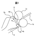
- FIG. 1 is a schematic cross-sectional view showing an embodiment of a cutting blade device that can be suitably used in the method for producing noodle strings of the present invention.
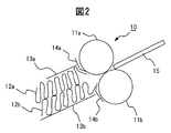
- FIG. 2 is a schematic cross-sectional view showing one embodiment of a cutting blade device used in a conventional noodle string manufacturing method.
- this cutting blade device 10 includes a pair of cutting blade rolls 11 a and 11 b for cutting a noodle strip into noodle strings, which are arranged to face each other with a predetermined clearance, and the cutting blade.
- this cutting blade device 10 For guiding the noodle strings 12a and 12b cut into the noodle string state by the roll, respectively, for “stripping” the holding plate 13a and the chute 13b and the noodle strings 12a and 12b from the cutting blade rolls 11a and 11b, respectively.
- Blade-like “scrap” members 14a and 14b are used in the example of FIG.
- the pressing plate 13a and the chute 13b constitute a “conduit” for guiding the cut noodle strings.
- a “wave conveyor” (not shown) for transferring the cut noodle strings 12 a and 12 b toward the left side of the drawing is disposed below the chute 13 b.
- noodle strip 15 is cut into upper and lower noodle strings 12a and 12b by a pair of cutting blade rolls 11a and 11b, and is composed of pressing plate 13a and chute 13b. Is guided by a “conduit” (that is, a guide member) and is transferred toward the left side of the drawing by the wave conveyor.
- a “conduit” that is, a guide member
- the noodle strands cut by the cutting blade rolls 11a and 11b are guided by the conduit and the speed and wave of the noodle strands cut out. Due to the difference in the speed of the conveyor, the noodle strings 12a and 12b are forcibly bent in the conduit to form waves, combined with the resistance of the conduit chute 13b and the conduit retainer 13a in the conduit. The size of the wave at this time is determined by the height of the space between the chute plate 13b and the conduit holding plate 13a.
- the chute plate 13b and the pressure plate 13a of the conduit are usually made of metal, the noodle strings 12a and 12b are strongly bent in the wave bending state, and in the subsequent steaming step, Such waves of “strong” noodle strings 12a and 12b are fixed.
- the pressing plate 13a that is, the lid
- the pressing plate 13a that is, the lid
- the upper and lower two waves have a uniform size. It becomes the wave of.
- Such a wave is rather excellent when aiming at a “uniform wave”.
- a cutting blade device 1 used in the present invention is a pair of cutting devices for cutting a noodle strip into noodle strings, which are arranged to face each other with a predetermined clearance.
- a “wave conveyor” (not shown) for transferring the cut noodle strings 2 a and 2 b toward the left side of the drawing is arranged below the chute 3.
- noodle strip 5 is cut into upper and lower noodle strings 2a and 2b by a pair of cutting blade rolls 1a and 1b, and by the action of blade-like “scrap” members 4a and 4b, It is “peeled off” from the cutting blade rolls 1 a and 1 b, then guided by a guide member composed of a chute 3, and transferred toward the left side of the drawing by the wave conveyor.
- the cutting blade device used in the present invention is characterized in that airflow supply means 6 for supplying airflow is provided to the noodle strings 2a and 2b after cutting.
- the cutting blade device 1 used in the present invention is an improvement of the cutting blade device used when producing the above-mentioned ordinary instant noodles. More specifically, an airflow supply means 6 (that is, an airflow pipe provided with an airflow discharge (or ejection) port) is provided between the upper and lower scrap members 4a and 4b arranged in the cutting blade device 1. Thus, the airflow is directly supplied to the noodle strings 2a and 2b cut by the cutting blade rolls 1a and 1b and peeled off by the scraping members 4a and 4b.
- an airflow supply means 6 that is, an airflow pipe provided with an airflow discharge (or ejection) port
- the air flow supply port of the air flow pipe 6 has a hole shape and a hole diameter capable of giving the air flow “direction”, so that each noodle string has a random direction ( Power).
- Power the contact points of each noodle strip can be suppressed as much as possible without applying the “longitudinal wave wave” that was important in the prior art to the noodle strip.
- the sticking between the noodle strings can be suppressed.
- a substantially straight noodle string can be easily obtained.
- noodle strings cut out from noodle strip 15 are divided into upper and lower two layers (that is, noodle strings 12a and 12b) inside a conduit (13a and 13b). Divide into two to form a strong longitudinal wave.
- the upper and lower scraping members 4a and 4a are removed because the conduit lid (13a in FIG. 2) arranged in the conventional cutting blade device is removed.
- the air flow supply means 6 By disposing the air flow supply means 6 between 4b, a directional air flow can be blown onto the noodle strings with respect to the upper and lower noodle bundles 12a and 12b.
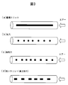
- the airflow supply means 6 is provided with a plurality of round holes as shown in the schematic perspective view of FIG. 3B, for example, and the airflow is discharged from the plurality of round holes.
- the air current is supplied to the noodle strings 2a and 2b.
- the wave formation of a longitudinal wave that is forcibly bent in the conduit (that is, a wave in the noodle string longitudinal direction) is suppressed. More specifically, the longitudinal waves are not formed at all or only suppressed longitudinal waves are formed. As a result, when the upper noodle strings 2a and the lower noodle strings 2b are irregularly shaped like a flat ring, a curve, or a zigzag, respectively, a longitudinal wave wave is formed at each contact point of the noodle strings. As with, it can be reduced.
- the air flow can be directly blown in the air against the noodle strings 2a and 2b peeled off by the scrapes, these noodle strings can be made to jump relatively easily, whereby the noodle strings Random directivity can be created for each of the lines 2a and 2b.
- the lid of the conduit it is possible to obtain a relatively large flat ring, curve, zigzag noodle strings 2a and 2b by removing the lid, but it prevents the noodle strings 2a and 2b from excessively blowing up.
- a jammer plate (not shown) for preventing popping out on the upper side of the scraper 4a.
- the noodle strings 2a and 2b are cut by the cutting blade rolls 1a and 1b, and the air current is supplied in the air immediately after being peeled off by the scraping members 4a and 4b. Since the surface of 2b can be dried instantaneously, the surfaces of the noodle strings 2a and 2b can be relatively cured. Thereby, together with the random resistance applied to the noodle strings based on the supply of the above-described airflow, the bundle of the noodle strings 2a and 2b as a whole is made "relatively sparse" on the wave conveyor. I can do it.
- the noodle string bundles of the upper and lower noodle strings 2a and 2b can be reliably separated and given a random orientation, the upper and lower noodle string bundles are prevented from crossing (intersection) with each other. Can be obtained on the wave conveyor in a state in which the noodle strings are reliably separated and no strong longitudinal wave is applied (that is, substantially linear).
- the above-described chute member 3 is used in the embodiment shown in FIG. 1, but this chute member 3 can be omitted.
- the noodle strings 2b peeled off by the lower scraping member 4b may be pressed against the chute member 3 by the airflow supplied from the airflow supply means 6.
- the airflow supply means 6 When such “pressing” occurs, there is a possibility that the lower noodle strings 2b hit the chute member 3 and the noodle strings 2b that have started to move irregularly as a result of the movement will be synchronized again. is there.
- the chute member 3 is arranged so that the angle of the chute member 3 is close to vertical so that the noodle strings 2b do not hit the chute member 3.
- the chute member 3 itself can be detached from the cutting blade device 1.
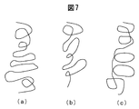
- FIG. 7 (schematic plan view of the noodle string track that can be obtained on the wave conveyor) shows an example of the noodle string track of the present invention.
- the trajectory of the noodle strings uses a stream of air to give each noodle string a random force, and the trajectory drawn by each noodle string becomes irregular, resulting in a flat ring, Draw a curve constantly and irregularly.
- FIG. 7A shows a mixture of flat wheels and curves
- FIG. 7B shows a case where the flat curves are shifted in the direction opposite to the traveling direction.
- Is an irregular mixture of flat and counterclockwise rings Is an irregular mixture of flat and counterclockwise rings.
- the trajectory drawn by each noodle string is normally in an unpredictable random state as shown in FIG.
- a single noodle string draws a ring repeatedly, and the noodle string does not synchronize with the adjacent noodle strings.
- a production method is disclosed in which when steamed in an overlapping state, a substantially straight noodle string can be obtained by stretching the noodle string after the steaming step.
- the present invention by blowing an air current on the noodle strings, the movement of one noodle string becomes irregular, such as drawing a circle, drawing a curve, or being in a zigzag state. Tend. Therefore, according to the method of the present invention, it is practically impossible to draw a repeated ring (that is, the phenomenon or effect obtained by the present invention is completely different).
- the present invention can also obtain the effect of instantly drying the noodle strings surface by using an air current, and the effect of suppressing the sticking between the noodle strings can be further promoted. Can be obtained.
- the airflow supply means in the present invention is not particularly limited with respect to its shape, structure, mechanism, etc., as long as it has a configuration (or structure) that enables airflow to be supplied to the cut noodle strings.
- the air flow supply means 6 is compared in terms of the space (arranged in the vicinity of the cutting blade rolls 1a and 1b in FIG. 1) and the influence (for example, electrical and magnetic influence) on the elements of other devices. It is preferable to have a configuration including a hollow tubular (tubular) member that is easy to achieve a simple structure.
- the air flow supply means 6 is not limited to the configuration including such a hollow tubular member as long as it is possible to supply the air flow to the cut noodle strings.
- the air flow supply means 6 is preferably a combination of a plurality of nozzles (for example, bundling a plurality of nozzles or arranging them in parallel).
- the intervals at which these are arranged may be equal intervals, and it is also preferable to combine unequal intervals and / or equal intervals as appropriate.
- the gas constituting the airflow from the airflow supply means 6 is not particularly limited.
- the gas is preferably normal air (air).
- another gas for example, nitrogen
- steam can also be suitably mixed with the said gas.
- the air flow supply means 6 used in the present invention is preferable if it has a size that can be arranged between the scraping members 4a and 4b of the cutting blade device 1 (FIG. 1).
- the shape of the airflow supply means 6 is not particularly limited, and may be appropriately selected from known shapes such as a round shape, a square shape, a triangle shape, an ellipse shape, and a plate shape as necessary.
- the air flow supply means 6 is provided in the vicinity of the upper and lower cutting blade rolls 1a and 1b, respectively, and the tips of the scrapers 4a and 4b (from the cutting blade roll 1a or 1b to the noodle strings 2a or 2b). It is preferable to arrange them at positions corresponding to the upper and lower sides of the portion where the peeling starts. In other words, when the noodle band 5 is cut with the cutting blade rolls 1a and 1b and peeled off with the scrapers 4a and 4b, the air current supply means 6 is provided between the upper noodle string bundle 2a and the lower noodle string bundle 2b. Is preferable.
- the airflow supply means 6 has a structure including a hollow tubular member (or pipe), it is preferable that a hole for discharging the airflow from the hollow tubular member is formed.
- the hollow tubular member for supplying airflow can be connected to, for example, an airflow compressor, an airflow blower, or the like, which is a supply source of the airflow. Considering the pressure of the airflow to be blown, it is preferable to use a high-pressure airflow compressor.
- the airflow outlet may be perforated at a position where it can be sprayed onto the upper and lower noodle string bundles 2a and 2b, and is preferably an outlet that produces an airflow (that is, a directional gas). From the point of creating such an air flow easily, as shown in FIG. 3B to FIG. 3D instead of the linear slit-shaped discharge port as shown in FIG. It is preferable to open a round hole, a square hole, a short slit-shaped hole or the like with a certain interval. In other words, by creating a space where airflow is generated and where airflow is not generated, the direction of the airflow can be easily obtained by making the hole round, square, or short slit. Become.
- this directional airflow may be sprayed perpendicularly to the noodle string bundle or obliquely.
- the noodle strings may be caught on the air flow supply means 6.
- the presence of noodle strings that are exposed to air currents and noodle strings that are not exposed to air currents (or only weak air currents) can change the trajectory of each noodle string in the air.
- the trajectory drawn by can be changed in various forms.
- non-uniform power it is preferable to apply "non-uniform power" to adjacent noodle strings using a plurality of "holes or slits” from the viewpoint that it is easy to apply a suitable air current to the whole noodle strings.
- a single “hole or slit” if an air flow is simply supplied from a single “hole or slit”, an almost uniform power will be applied to the adjacent noodles. It is somewhat difficult to apply "non-uniform power" to adjacent noodle strings.
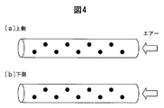
- the airflow supply means 6 is formed by a hollow round bar, It is preferable to open the mold holes in a staggered type. As a result, the discharge angle and discharge position of the airflow are shifted, so that a directional airflow can be blown onto the noodle strings.
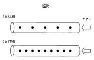
- an airflow outlet is opened in a “staggered” shape in FIG.
- opening the airflow outlets in the “staggered shape” of b) it becomes easier to blow directional air on each noodle string.
- the ejection angle can be varied.
- the airflow outlet shown in FIG. 5 (a) can be opened above the hollow cylindrical member, and the airflow outlet shown in FIG. 5 (b) can be opened below the member.
- the aspect which opens the airflow discharge port arranged in a straight line may be sufficient.
- FIG. 5 by changing the pitch of the holes, a portion where the air hits the noodle strings and a portion where the air does not hit can be formed. As a result, the trajectory of each noodle string can be easily changed. I can do it.
- the “staggered” airflow outlet shown in FIG. 6A is opened above the hollow cylindrical member, and the “straight” airflow outlet shown in FIG. 6B is opened below the member. You can also. As described above, it is also effective to change the way of opening the airflow outlet between the upper side and the lower side of the hollow cylindrical member. A random force can be applied to each noodle string.
- each noodle strip from the point that it is easy to randomly blow a directional airflow to each noodle strip, (noodles that hit the airflow, noodles that do not hit the airflow, when the airflow hits, etc.
- the trajectory drawn by each noodle string can be changed irregularly.
- the noodle strings are shaken like rampaging in the air, and the noodle strings draw flat rings of different sizes on the wave conveyor. It can be drawn in the reverse direction, the lateral direction of travel, and the diagonal direction of travel.
- each noodle string can be randomly arranged on the wave conveyor in an unpredictable manner, and as a result, the noodle string (even without a strong longitudinal wave applied to the noodle string) It is possible to effectively reduce the contact of each one.
- this random movement is caused by the air current and the noodle strings danced in the air by the air current collide, and the impact of the impact also changes the trajectory of the noodle strings, making the random movement more unpredictable. Obtainable.
- the “instant noodle” or “instant dry noodle” in the present invention is preferably any of a so-called stew type, a type in which hot water is added and cooked, and the like.
- the noodle material is not particularly limited. That is, the material conventionally used for manufacturing instant noodles can be used without particular limitation. More specifically, for example, the main raw materials and auxiliary raw materials described in paragraphs 52 to 62 of “Introduction to New Instant Noodles” published by Japan Food Newspaper Company (1998), supervised by the Japan Instant Food Industry Association In the present invention, it can be used without any particular limitation.
- the main raw material that can be used in the present invention can be blended with, for example, wheat flour, barley flour, starch and the like.
- main usable materials for example, ASW (Australia white intermediate wheat, protein around 10%) for wheat flour, HRW (American red hard wheat, around 11% protein) for starch, and potato starch for starch , Tapioca starch, waxy corn starch, corn starch, wheat starch and the like, and etherified starch, esterified starch, cross-linked starch, oxidized starch and the like obtained using these as raw materials.
- auxiliary materials include citrus, phosphates, salts, thickening polysaccharides, eggs, gluten and the like.
- noodle manufacturing method As a noodle-making method, wheat flour is used as a main raw material, and starch, gluten and the like are blended as necessary, and auxiliary materials including salt, citrus and the like are mixed with water and a dough can be prepared.
- the airflow of the present invention is blown onto the noodle strings. More specifically, it is preferable that the air flow supply means 6 is arranged between the upper noodle string bundle 2a and the lower noodle string bundle 2b at the time of peeling with a scraper (4a and 4b in FIG. 1).
- the hollow tubular member constituting the airflow supply means 6 is provided with a hole through which the airflow is discharged, and the hollow tubular member for supplying the airflow is connected to an airflow compressor, an airflow blower or the like that is an airflow supply source. If it is, it is preferable.
- the airflow outlet may be perforated at a position where a directional airflow can be sprayed on the upper and lower noodle strings, and may be sprayed vertically or obliquely on the noodle strings.
- a gap (hereinafter referred to as a pitch) between the airflow outlet and the adjacent airflow outlet is opened to some extent. More specifically, by making the pitch from 2 mm to 20 mm, the place where the air current comes out and the place where it doesn't come out. Can be changed. When the pitch is wider than 20 mm, although it depends on the width of the noodle strings, there are many portions where the air current does not hit, and the number of places where the trajectory of the noodle strings cannot be changed tends to increase. Further, when the pitch is 2 mm or less, the direction of the airflow becomes difficult to be performed, so it is somewhat difficult to change the activation of each noodle string. Usually, the pitch is preferably about 2 mm to 20 mm, and more preferably an interval of 5 mm to 15 mm. It is particularly preferable that the pitch between the airflow outlets and the adjacent airflow outlets be 5 to 10 mm apart.
- the hole shape of the airflow outlet may be devised as necessary, such as a round shape, a square shape, a triangle shape, or a slit shape.
- a directional airflow can be supplied by opening the hole with a diameter of about 0.2 mm to about 3 mm. If it is ⁇ 3 mm or more, it tends to be difficult to ensure the opening ratio of the total number of outlets relative to the size of the hollow tubular member. On the other hand, when it is ⁇ 0.2 mm or less, processing of the discharge port tends to be difficult.
- Airflow pressure The airflow pressure can be appropriately controlled according to the state of the noodle strings obtained. If the air current is too strong, the noodle strings may be blown more than necessary, causing inconveniences such as falling off the wave conveyor. For example, it is preferable to spray at a position of 0.02 Mpa to 0.3 Mpa, but it is more preferable to spray at a position of 0.05 Mpa to 0.2 Mpa. From the viewpoint of exhibiting the effect of the above, it is more preferable.
- the pressure of this air flow is a value measured by adjusting the pressure with a precision regulator (manufacturer: SMC Corporation, model number: IR3010-03BG) attached 1 m before the air piping.
- a precision regulator manufactured by SMC Corporation, model number: IR3010-03BG
- the discharge angle and the discharge position are irregular by making the air flow supply means 6 with a hollow cylindrical member (hollow round bar) and opening the round holes in a staggered pattern (as shown in FIG. 5). Therefore, it is more effective as compared with a mode in which holes are simply formed in a straight line.
- the upper noodle string bundle can draw a random trajectory only by supplying the air current only to the upper noodle string bundle 2a.
- the lower noodle string bundle 2b becomes a synchronized noodle string.
- the same effect can be obtained by supplying airflow only to the lower noodle strings without supplying airflow to the upper noodle strings.
- the noodle strings may be entangled with the air current supply means 6 when the air current is not supplied to the upper noodle strings.
- the ⁇ -treatment method in the present invention can be optionally carried out by boiling with boiling hot water or steaming with steam, but it is more preferable to use a steamer using steam.
- ⁇ Stretching process> By stretching steamed noodles, each meal can be cut with a stable weight. In this stretching step, it is preferable to cut each portion of the stretched portion with the aqueous solution attached to the steamed noodles.
- an aqueous solution By attaching an aqueous solution to the surface of the noodle strings, it is possible to peel off the light noodle strings.
- a spray nozzle, a shower, immersion, or the like may be used.
- a loosening device such as that shown in Japanese Patent Application No. 2010-537611 for noodles cut into one meal. It is desirable because it can further loosen the sticking of light noodle strings.
- the instant noodles of the present invention can be obtained by forming and filling the noodle strings obtained by the above-described method into a drying basket one by one and performing a drying process.
- frying with oil, frying and drying method, hot air drying method of drying with hot air, and the like can be used as necessary.
- the final moisture may be dried to 2 to 3%, and in the hot air drying method, the final moisture may be dried to 6 to 14%.
- drying conditions such as the drying temperature, the conventional method may be supplied as it is. .
- the “degree of sticking” (average of three results) obtained in each test is preferably 35% or less.
- the “sticking degree” is more preferably 25% or less, and further preferably 20% or less (particularly 15% or less).
- a cutting blade device having the configuration shown in FIG. 1 was used.
- the size of each element was as follows.
- Cutting blade roll (iron) 1a and 1b Diameter 37 mm, width 210 mm Chute 3 (stainless steel): thickness 1.5mm Waste 4a and 4b (made of brass): 1mm thick
- Noodle string condition Cutting blade No. 24 round shape, cutting blade roll rotation speed 205 rotation / min, noodle string thickness of 1.5 mm, no lid of conduit, scraped width 35 mm
- Diameter of airflow supply means 6 ⁇ 10 mm
- Airflow outlet 1 mm hole, pitch 10 mm, 15-degree staggered type (see FIGS. 4 (a) and 4 (b))
- Pressure is supplied to the noodle strings at 0.1 MPa (megapascals). It was set to 4 m / min, and after obtaining a random, substantially linear noodle string bundle, steamed at 0.5 kg / cm 2 for 2 minutes and cut into noodle weight 100 g to obtain steamed noodles.
- the steamed noodles obtained as described above were immersed in fresh water for 10 seconds, and the noodle strands subjected to the immersion treatment were forced at 1200 revolutions using the loosening device disclosed in FIG. 8 (a) of Japanese Patent Application No. 2010-537611. 1 time (about 1 second). The “sticking” of noodles of noodle strands loosened by the loosening device was counted.
- the method of counting sticking of noodle strings was classified into those that could be taken out as a single noodle string, and those that could not be taken out, with respect to the noodle strings that were loosened with the loosening device.
- the pinching noodle strings are shaken three times at a speed of about 0.7 seconds at a distance of 30 cm. If it was, it was judged to be “unraveled”.
- the noodle strings that were not loosened even when shaken in this way and the noodle strings that were firmly attached were counted as being “attached”. At this time, if two were attached, it was counted as two, and if five were attached in a bundle, it was counted as five.
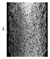
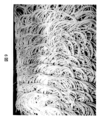
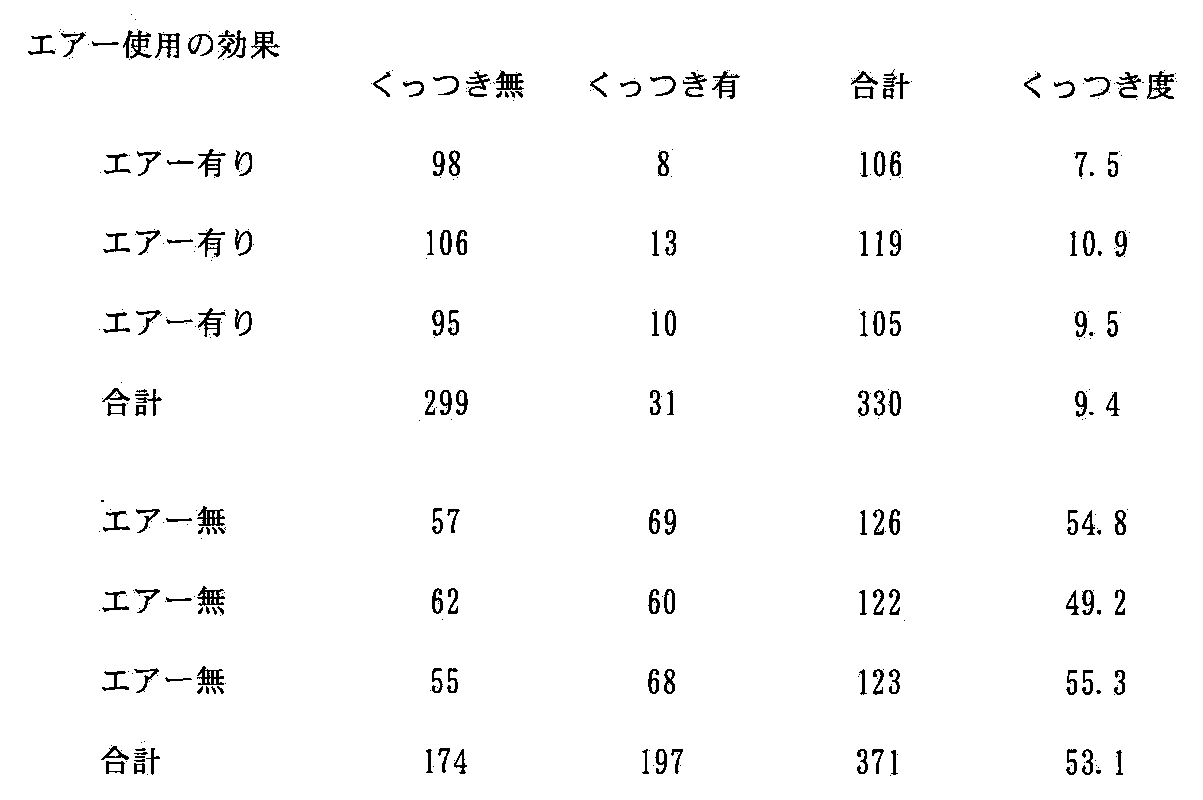
- Table 1 shows the results. Moreover, the photograph of the noodle string bundle on the wave conveyor with and without airflow is shown in FIG. 8 (in the case of airflow) and FIG. 9 (in the case of no airflow). The reason why the “total number of noodles” is different in each noodle strand is because the number of each noodle strand is slightly different because the noodle strand is divided by weight.
- Example 1 A flour raw material of 950 g of wheat flour (ASW, protein 9.5%) and potato starch 50 g, kneaded with 3 g of sodium carbonate and 10 g of sodium chloride dissolved in 350 ml of water, rolled, and cut with a round blade 20
- a noodle string having a thickness of 1.30 mm is cut from a cutting blade roll (diameter: 37 mm) at a rotation speed of 200 rpm / min, a scrap width of 35 mm, an air flow supply means 6 ⁇ 10 mm (1 mm hole, pitch 10 mm, 15-degree zigzag type, see FIG.
- Example 2 A flour raw material of 900 g of wheat flour (ASW, protein 9.5%) and 100 g of potato starch, kneaded with 3 g of sodium carbonate and 10 g of salt dissolved in 330 ml of water, rolled, and cut with a 20-edge round shape.
- a noodle string having a thickness of 1.30 mm is cut into a cutting blade roll (diameter: 37 mm) at a rotation speed of 200 rpm / min, a scrape width of 35 mm, and an air flow supply means 6 ⁇ 10 mm (1 mm hole, pitch 10 mm, linear type, FIG. The airflow was supplied to the noodle strings at a pressure of 0.1 MPa.
- the noodle strand bundle is continuously steamed and then 30 ml of fresh water is showered per noodle strand (100 g steamed noodle).
- the noodle strings cut into a shower noodle weight of 115 g were put into a basket and fried at a fried temperature of 150 ° C. for 2 minutes by an oil frying method to obtain instant fried noodles having a final moisture content of 2%.
- Example 3 A flour raw material of 950 g of wheat flour (ASW, protein 9.5%) and 50 g of tapioca starch is kneaded and rolled with 5 ml of sodium carbonate and 10 g of salt dissolved in 350 ml of water, and the cutting edge is 16 round.
- a noodle wire with a thickness of 1.20 mm is cut from a cutting blade roll (diameter 37 mm) at a rotation speed of 200 rotations / min, a scrap width of 35 mm, and an air current supply means 6 ⁇ 10 mm (1 mm hole, pitch 10 mm, 15 degree staggered type, see FIG. 6 type 1) The airflow was supplied to the noodle strings at a pressure of 0.15 MPa.
- the speed of the wave conveyor is set to 4.5 m / min, and after obtaining a random noodle strand bundle, the noodle strand bundle is continuously steamed, and then the steamed noodle strip is cut into 100 g noodle weight per serving.
- 20 ml (Fuji Oil Co., Ltd. “Soya Five S” 1.0% aqueous solution) is sprayed, and air-flow molding filling is performed on a ⁇ 120 mm drying mold. Thereafter, it was dried for 40 minutes in a dryer adjusted to a temperature of 80 ° C. and a wind speed of 4 m / s to obtain instant hot-air dried noodles having a final moisture content of 10%.
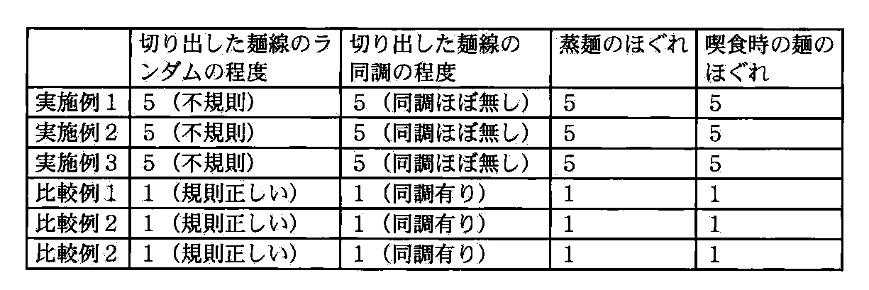
- the noodle strings obtained according to the present invention have unpredictable random movements. That is, rather than constantly drawing a circle, the wheel, curve, and the direction of travel are moving in a reverse direction, lateral direction, and forward direction. From the comparison between Example 3 and Comparative Example 3, it can be understood that the effect is substantially maintained even in hot-air dried noodles.
- the effect of the present invention is that by applying an air flow directly to the noodle strings, random movement can be given to the noodle strings, and no strong longitudinal wave wave is applied to the contact points of the noodle strings. Both can be reduced. For this reason, in the present invention, it is possible to suppress sticking of noodle strings during steaming without applying a strong longitudinal wave. Furthermore, since the moisture on the surface of the noodle strings at the time of cutting can be blown off by applying an air current, a noodle string with better looseness can be obtained.
Abstract
Description
前記麺帯を前記切刃ロールに通して、該麺帯を麺線状に切り出す工程と、
該麺線を、切刃ロールからカスリ部材で剥ぎ取り、上下の麺線束に分離させる工程と、
該切り出し後の麺線に対して、前記気流供給手段から気流を供給する工程とを少なくとも有することを特徴とするものである。 The instant dry noodle manufacturing method of the present invention is based on the above knowledge, and more specifically, using a rotary cutting device including at least a pair of cutting blade rolls, a scraping member, and an airflow supply means, A method for producing a noodle string, which is cut into noodle strings,
Passing the noodle strip through the cutting blade roll and cutting the noodle strip into a noodle strand;
Peeling the noodle strings from the cutting blade roll with a scraping member and separating the noodle strings into upper and lower noodle string bundles;
A step of supplying an airflow from the airflow supply means to the cut-out noodle strings.
一対の切刃ロールと、カスリ部材と、気流供給手段とを少なくとも含む回転式切り出し装置を用いて、麺帯を麺線状に切り出す麺線の製造方法であって;
前記麺帯を前記切刃ロールに通して、該麺帯を麺線状に切り出す工程と、
該麺線を、切刃ロールからカスリ部材で剥ぎ取り、上下の麺線束に分離させる工程と、
該切り出し後の麺線に対して、前記気流供給手段から気流を供給する工程とを少なくとも有することを特徴とする麺線の製造方法。 [1]
A method for producing a noodle string, in which a noodle strip is cut into a noodle string using a rotary cutting device including at least a pair of cutting blade rolls, a scrap member, and an airflow supply means;
Passing the noodle strip through the cutting blade roll and cutting the noodle strip into a noodle strand;
Peeling the noodle strings from the cutting blade roll with a scraping member and separating the noodle strings into upper and lower noodle string bundles;
A method for producing noodle strings, comprising: supplying at least airflow from the airflow supply means to the cut noodle strings.
前記気流が、前記麺線の移動方向に向かって、該麺線を押し出す方向に作用する気流である〔1〕に記載の麺線の製造方法。 [2]
The method for producing noodle strings according to [1], wherein the air current is an air current acting in a direction of pushing out the noodle strings in the moving direction of the noodle strings.
前記気流供給手段が、前記下側麺線と、上側麺線との間に、前記気流を供給するものである〔1〕または〔2〕に記載の麺線の製造方法。 [3]
The method for producing noodle strings according to [1] or [2], wherein the air current supply means supplies the air current between the lower noodle strings and the upper noodle strings.
前記気流供給手段から麺線に供給される気流が、方向性のある気流である〔1〕~〔3〕のいずれか1項に記載の麺線の製造方法。 [4]
The method for producing a noodle string according to any one of [1] to [3], wherein the airflow supplied from the airflow supply means to the noodle strings is a directional airflow.
前記気流供給手段が、中空の円柱状または角柱状の管状部材を含む〔1〕~〔4〕のいずれか1項に記載の麺線の製造方法。 [5]
The method for producing noodle strings according to any one of [1] to [4], wherein the air flow supply means includes a hollow cylindrical or prismatic tubular member.
前記気流供給手段に、複数の気流排出口が設けられている〔1〕~〔5〕のいずれか1項に記載の麺線の製造方法。 [6]
The method for producing noodle strings according to any one of [1] to [5], wherein the airflow supply means is provided with a plurality of airflow outlets.
前記気流排出口が、多角形のスリット状、円状または楕円状である〔6〕に記載の麺線の製造方法。 [7]
The method for producing noodle strings according to [6], wherein the air flow outlet has a polygonal slit shape, a circular shape, or an elliptical shape.
前記気流供給手段が、上下切刃ロールの間の位置に配置され、カスリ部材により剥がされた上下各麺線束の間に、該気流供給手段からの気流が供給される〔1〕~〔7〕のいずれか1項に記載の麺線の製造方法。 [8]
The airflow supply means is disposed at a position between the upper and lower cutting blade rolls, and the airflow from the airflow supply means is supplied between the upper and lower noodle strings bundles peeled off by the scraping member [1] to [7] The manufacturing method of the noodle string of any one of Claims 1.
前記気流供給手段が一対の切刃ロールの間に配置され、且つ上下各麺線束に直接気流を供給する位置に、該気流供給手段から気流が供給される〔1〕~〔8〕のいずれか1項に記載の麺線の製造方法。 [9]
Any one of [1] to [8], wherein the airflow supplying means is disposed between a pair of cutting blade rolls, and the airflow is supplied from the airflow supplying means to a position where the airflow is supplied directly to the upper and lower noodle string bundles. 2. A method for producing a noodle string according to item 1.
一対の切刃ロールと、カスリ部材と、気流供給手段とを少なくとも含む回転式切り出し装置を用いて、麺帯を麺線状に切り出す麺線の製造方法であって;
前記麺帯を前記切刃ロールに通して、該麺帯を麺線状に切り出す工程と、
該麺線を、切刃ロールからカスリ部材で剥ぎ取り、上下の麺線束に分離させる工程と、
該切り出し後の麺線に対して、前記気流供給手段から気流を供給して、該麺線に実質的に縦波ウェーブを形成させずに、略扁平状の麺線束を形成する工程と、
前記麺線をα化し、次いで乾燥させる工程と、を少なくとも有することを特徴とする即席乾燥麺の製造方法。 [10]
A method for producing a noodle string, in which a noodle strip is cut into a noodle string using a rotary cutting device including at least a pair of cutting blade rolls, a scrap member, and an airflow supply means;
Passing the noodle strip through the cutting blade roll and cutting the noodle strip into a noodle strand;
Peeling the noodle strings from the cutting blade roll with a scraping member and separating the noodle strings into upper and lower noodle string bundles;
Supplying the airflow from the airflow supply means to the cut noodle strings, and forming a substantially flat noodle string bundle without substantially forming longitudinal wave waves on the noodle strings;
A process for producing instant dried noodles, wherein the process comprises at least a step of converting the noodle strings into α and then drying them.
前記略扁平状の麺線束が、不規則な動きをした各麺線が集まって形成されたものである〔10〕に記載の即席乾燥麺の製造方法。 [11]
The method for producing instant dried noodles according to [10], wherein the substantially flat noodle string bundle is formed by gathering irregularly moving noodle strings.
前記麺線束の略不規則な動きが、輪状、横波状、および/又はジグザグ状の軌道を与える〔11〕に記載の即席乾燥麺の製造方法。 [12]
The method for producing instant dried noodles according to [11], wherein the substantially irregular movement of the noodle string bundle provides a circular, transverse wave, and / or zigzag orbit.
前記α化の手段として、蒸気を用いる蒸し機を使用する〔10〕~〔12〕のいずれか1項に記載の即席乾燥麺の製造方法。 [13]
The method for producing instant dry noodles according to any one of [10] to [12], wherein a steamer using steam is used as the means for pregelatinization.
一対の切刃ロールと、カスリ部材と、気流供給手段とを少なくとも含む回転式切り出し装置を用いて、麺帯を麺線状に切り出すことにより製造された麺線であって;
該切り出し後の麺線が、35%以下の「くっつき度」を有することを特徴とする即席乾燥麺用の麺線。 [14]
A noodle string produced by cutting a noodle strip into a noodle string using a rotary cutting device including at least a pair of cutting blade rolls, a scrap member, and an airflow supply means;
The noodle strings for instant dry noodles, wherein the noodle strings after cutting have a “sticking degree” of 35% or less.
本発明の麺線の製造方法においては、一対の切刃ロールと、カスリ部材と、気流供給手段とを少なくとも含む回転式切り出し装置を用いて、麺帯を麺線状に切り出す麺線の製造方法であって;前記麺帯を前記切刃ロールに通して、該麺帯を麺線状に切り出す工程と;該麺線を、切刃ロールからカスリ部材で剥ぎ取り、上下の麺線束に分離させる工程と;該切り出し後の麺線に対して、前記気流供給手段から気流を供給する工程とを少なくとも有することが特徴である。 (Manufacturing method of noodle strings)
In the method for producing noodle strings according to the present invention, a method for producing noodle strings that cuts noodle strips into noodle strings using a rotary cutting device including at least a pair of cutting blade rolls, a scrap member, and an air flow supplying means. A step of passing the noodle strip through the cutting blade roll and cutting the noodle strip into a noodle strip, and peeling the noodle strip from the cutting blade roll with a scraping member to separate the noodle strip into upper and lower noodle strip bundles. And a step of supplying an air flow from the air flow supply means to the cut noodle strings.
本発明の麺線は、一対の切刃ロールと、カスリ部材と、気流供給手段とを少なくとも含む回転式切り出し装置を用いて、麺帯を麺線状に切り出すことにより製造された麺線である。本発明の麺線は、該切り出し後の麺線が、35%以下の「くっつき度」を有することが特徴である。この「くっつき度」は、後述する方法によって好適に測定することができる。該「くっつき度」は、25%以下であることがより好ましく、20%以下(特に15%以下)であることが更に好ましい。 (Noodle line)
The noodle string of the present invention is a noodle string manufactured by cutting a noodle band into a noodle string shape using a rotary cutting device including at least a pair of cutting blade rolls, a scrap member, and an air flow supply means. . The noodle strings of the present invention are characterized in that the noodle strings after cutting have a “sticking degree” of 35% or less. This “sticking degree” can be suitably measured by a method described later. The “sticking degree” is more preferably 25% or less, and further preferably 20% or less (particularly 15% or less).
図1は、本発明の麺線製造方法に好適に使用可能な切刃装置の一態様を示す模式断面図である。他方、図2は、従来の麺線製造方法に使用される切刃装置の一態様を示す模式断面図である。 (Cutting device)
FIG. 1 is a schematic cross-sectional view showing an embodiment of a cutting blade device that can be suitably used in the method for producing noodle strings of the present invention. On the other hand, FIG. 2 is a schematic cross-sectional view showing one embodiment of a cutting blade device used in a conventional noodle string manufacturing method.
先ず、従来の切刃装置を用いた場合について述べる。図2を参照して、この切刃装置10は、所定のクリアランスを介して対向して配置された、麺帯を麺線に切断するための一対の切刃ロール11aおよび11bと、該切刃ロールによって麺線状態に切断された麺線12aおよび12bをそれぞれガイドするための、押さえ板13aおよびシュート13bと、麺線12aおよび12bを、それぞれ切刃ロール11aおよび11bから「はぎ取る」ための、ブレード状「カスリ」部材14aおよび14bとを含む。この図2の例では、上記押さえ板13aおよびシュート13bが、切り出された麺線をガイドするための「導管」を構成している。なお、図2中、シュート13bの下方には、図面の左側に向かって、切断された麺線12aおよび12bを移送させるための「ウェーブコンベアー」(図示せず)が、配置されている。 (Conventional cutting blade device)
First, a case where a conventional cutting blade device is used will be described. Referring to FIG. 2, this
図1を参照して、本発明の一態様において、本発明に用いる切刃装置1は、所定のクリアランスを介して対向して配置された、麺帯を麺線に切断するための一対の切刃ロール1aおよび1bと、該切刃ロールによって麺線状態に切断された麺線2aおよび2bをそれぞれガイドするためのシュート3と、麺線2aおよび2bを、それぞれ切刃ロール1aおよび1bから「はぎ取る」ための、ブレード状「カスリ」部材4aおよび4bとを含む。なお、図1中、シュート3の下方には、図面の左側に向かって、切断された麺線2aおよび2bを移送させるための「ウェーブコンベアー」(図示せず)が、配置されている。 (Cut blade device of the present invention)
Referring to FIG. 1, in one aspect of the present invention, a cutting blade device 1 used in the present invention is a pair of cutting devices for cutting a noodle strip into noodle strings, which are arranged to face each other with a predetermined clearance. The blade rolls 1a and 1b, the chute 3 for guiding the noodle strings 2a and 2b cut into the noodle string state by the cutting blade roll, respectively, and the noodle strings 2a and 2b from the cutting blade rolls 1a and 1b, respectively, And blade-like “scrap”
本発明に用いる切刃装置のメカニズムを説明する。従来の切刃の模式図を図2に示す。本発明に用いる切刃装置の模式図を図1に示す。 <Detailed mechanism of the cutting blade device>
The mechanism of the cutting blade device used in the present invention will be described. A schematic diagram of a conventional cutting blade is shown in FIG. A schematic diagram of a cutting blade device used in the present invention is shown in FIG.
本発明の麺線の軌道の例を、図7(ウェーブコンベアー上で得ることができる麺線軌道の模式平面図)をに示す。麺線の軌道は、気流を使い各麺線にランダムな力を与えることで、一本一本の麺線の描く軌道は不規則な動きになり、結果的に扁平状の輪を描いたり、カーブを描いたりを絶えず不規則に行う。図7(a)は、扁平状の輪とカーブが混在しているものであり、図7(b)は、扁平状のカーブが進行方向逆方向にずれているものであり、図7(c)は、扁平状の輪が左回り、右回りと不規則に混在しているものである。本発明において、気流を麺線に吹き付けることにより、図7に示したように、各麺線は描く軌道が、通常は、予測不可能なランダムな状態となる。 (The trajectory drawn by the noodle strings when air current is supplied)
FIG. 7 (schematic plan view of the noodle string track that can be obtained on the wave conveyor) shows an example of the noodle string track of the present invention. The trajectory of the noodle strings uses a stream of air to give each noodle string a random force, and the trajectory drawn by each noodle string becomes irregular, resulting in a flat ring, Draw a curve constantly and irregularly. FIG. 7A shows a mixture of flat wheels and curves, and FIG. 7B shows a case where the flat curves are shifted in the direction opposite to the traveling direction. ) Is an irregular mixture of flat and counterclockwise rings. In the present invention, by blowing an air current on the noodle strings, the trajectory drawn by each noodle string is normally in an unpredictable random state as shown in FIG.
上記においては、本発明の図1に示す態様であって、しかも気流供給手段6が、管状(ないし配管)の部材を含む態様について、主に説明した。このような態様においては、該気流供給手段6を構成する管状部材に、図3(b)に示すような、複数の丸孔が形成されている。以下では、上述した態様以外の態様について説明を加える。 (Other aspects)
In the above, the embodiment shown in FIG. 1 of the present invention and the embodiment in which the airflow supply means 6 includes a tubular (or piping) member has been mainly described. In such an embodiment, a plurality of round holes as shown in FIG. 3B are formed in the tubular member constituting the air flow supply means 6. Below, description is added about aspects other than the aspect mentioned above.
本発明における気流供給手段は、切り出し後の麺線に対して、気流を供給することを可能とする構成(ないし構造)である限り、その形状、構造、メカニズム等に関しては、特に制限されない。例えば、気流供給手段6は、図1の切刃ロール1aおよび1bの近傍に配置する際のスペース、他の装置の要素に与える影響(例えば、電気、磁気的な影響)の点からは、比較的単純な構造とすることが容易な、中空管状(筒状)部材を含む構成を有することが好ましい。 (Configuration of air flow supply means)
The airflow supply means in the present invention is not particularly limited with respect to its shape, structure, mechanism, etc., as long as it has a configuration (or structure) that enables airflow to be supplied to the cut noodle strings. For example, the air flow supply means 6 is compared in terms of the space (arranged in the vicinity of the cutting blade rolls 1a and 1b in FIG. 1) and the influence (for example, electrical and magnetic influence) on the elements of other devices. It is preferable to have a configuration including a hollow tubular (tubular) member that is easy to achieve a simple structure.
本発明で使用可能な気流供給手段6の配置箇所について、図1を参照しつつ説明する。 (Location of air supply means)
The arrangement | positioning location of the airflow supply means 6 which can be used by this invention is demonstrated referring FIG.
気流供給手段6が中空管状部材(ないし配管)を含む構造である態様においては、該中空管状部材から気流が排出するための穴が開けられていることが好ましい。気流供給のための中空管状部材は、例えば、該気流の供給源である気流コンプレッサー、気流ブロアー等に接続することができる。吹き付ける気流の圧力等を考慮すれば、高圧の気流コンプレッサーを使用するのが好ましい。 (Structure of air flow supply means)
In the aspect in which the airflow supply means 6 has a structure including a hollow tubular member (or pipe), it is preferable that a hole for discharging the airflow from the hollow tubular member is formed. The hollow tubular member for supplying airflow can be connected to, for example, an airflow compressor, an airflow blower, or the like, which is a supply source of the airflow. Considering the pressure of the airflow to be blown, it is preferable to use a high-pressure airflow compressor.
本発明における「即席麺」ないし「即席乾燥麺」は、いわゆる煮込みタイプ、熱湯を注加して調理するタイプ、等のいずれでも好ましい。 (Immediate noodles)
The “instant noodle” or “instant dry noodle” in the present invention is preferably any of a so-called stew type, a type in which hot water is added and cooked, and the like.
本発明においては、麺の材料は、特に制限されない。すなわち、従来より即席麺の製造に使用されている材料を、特に制限無く使用することが出来る。より具体的には、例えば、社団法人 日本即席食品工業協会監修「新・即席めん入門」日本食糧新聞社発行(平成10年)の第52~62項に記載されている主原料、副原料を、本発明において特に制限なく使用することが出来る。 <Process for making dough> (Noodle ingredients)
In the present invention, the noodle material is not particularly limited. That is, the material conventionally used for manufacturing instant noodles can be used without particular limitation. More specifically, for example, the main raw materials and auxiliary raw materials described in paragraphs 52 to 62 of “Introduction to New Instant Noodles” published by Japan Food Newspaper Company (1998), supervised by the Japan Instant Food Industry Association In the present invention, it can be used without any particular limitation.
本発明において使用可能な主原料は、例えば、小麦粉、大麦粉、澱粉等をブレンドすることが可能である。中でも、好適な使用可能な主原料としては、例えば、小麦粉ではASW(オーストラリア産白色中間質小麦、蛋白質10%前後)、HRW(アメリカ産赤色硬質小麦、蛋白質11%前後)、澱粉では、馬鈴薯澱粉、タピオカ澱粉、ワキシーコーンスターチ、コーンスターチ、小麦澱粉などで良く、また、これらを原料として得られるエーテル化工澱粉、エステル化工澱粉、架橋化工澱粉、酸化工澱粉等が挙げられる。 (Main raw material)
The main raw material that can be used in the present invention can be blended with, for example, wheat flour, barley flour, starch and the like. Among the main usable materials, for example, ASW (Australia white intermediate wheat, protein around 10%) for wheat flour, HRW (American red hard wheat, around 11% protein) for starch, and potato starch for starch , Tapioca starch, waxy corn starch, corn starch, wheat starch and the like, and etherified starch, esterified starch, cross-linked starch, oxidized starch and the like obtained using these as raw materials.
本発明において、使用可能な副原料としては、例えば、かんすい、リン酸塩、塩、増粘多糖類、卵、グルテン等が挙げられる。 (Sub-material)
In the present invention, examples of auxiliary materials that can be used include citrus, phosphates, salts, thickening polysaccharides, eggs, gluten and the like.
製麺方法としては小麦粉を主原料として使い、必要に応じて澱粉、グルテン等をブレンドし、食塩、かんすい等を含む副原料と、水とをミキサーにより混捏してドウを作成することができる。 (Noodle manufacturing method)
As a noodle-making method, wheat flour is used as a main raw material, and starch, gluten and the like are blended as necessary, and auxiliary materials including salt, citrus and the like are mixed with water and a dough can be prepared.
ドウを用い、ロール圧延により、圧延し、薄く延ばした麺帯を、切刃装置にて連続的に切り出す工程において、本発明の気流を麺線に吹き付ける構造にする。より具体的には、カスリ(図1の4aおよび4b)で剥がした時点で、上側の麺線束2aと下側の麺線束2bの間に気流供給手段6が配置されていれば好ましい。気流供給手段6を構成する中空管状部材には、気流が排出する穴が開けられており、該気流供給のための中空管状部材は、気流の供給源である気流コンプレッサー、気流ブロアー等に接続されていれば好ましい。吹き付ける気流の圧力等を考慮すれば、高圧の気流コンプレッサーを使用するのが好ましい。また、気流の排出口は、方向性ある気流を上下の麺線束に吹き付けることが出来る位置に穴あけをすれば良く、麺線束に垂直に吹き付けたり、斜めに吹き付けたりすればよい。麺線束の進行方向逆向きに気流をかける場合には、気流供給手段6に麺線が引っかかってしまう可能性に注意する必要がある。 <Cut out process>
In the process of continuously cutting the thinly stretched noodle strip using a dough using a dough, using a dough, the airflow of the present invention is blown onto the noodle strings. More specifically, it is preferable that the air flow supply means 6 is arranged between the upper
方向性ある気流を供給するためには、気流の排出口と、隣接する気流の排出口の隙間(以後ピッチ)は、ある程度空ける方が好ましい。より具体的には、ピッチ2mmから20mm程度に空けることで、気流の出るところと出ないところが出来るために、麺線には、気流が当たる麺線と気流が当たらない麺線とで大きく軌道を変えることが出来る。ピッチが20mmよりも広がると麺線の幅にもよるが、気流が当たらない部分が多くなり、麺線の軌道を変えられない箇所が増えてしまう傾向がある。また、ピッチが2mm以下になると、気流の方向性が出来にくくなるので、各麺線の起動を変えることが、やや難しくなる傾向がある。通常、ピッチは2mmから20mm位が好ましく、ピッチ5mmから15mm間隔が更に好ましい。特に好ましくは、気流の排出口と、隣接する気流の排出口のピッチ5mmから10mm間隔で空けることが望ましい。 (Airflow outlet)
In order to supply a directional airflow, it is preferable that a gap (hereinafter referred to as a pitch) between the airflow outlet and the adjacent airflow outlet is opened to some extent. More specifically, by making the pitch from 2 mm to 20 mm, the place where the air current comes out and the place where it doesn't come out. Can be changed. When the pitch is wider than 20 mm, although it depends on the width of the noodle strings, there are many portions where the air current does not hit, and the number of places where the trajectory of the noodle strings cannot be changed tends to increase. Further, when the pitch is 2 mm or less, the direction of the airflow becomes difficult to be performed, so it is somewhat difficult to change the activation of each noodle string. Usually, the pitch is preferably about 2 mm to 20 mm, and more preferably an interval of 5 mm to 15 mm. It is particularly preferable that the pitch between the airflow outlets and the adjacent airflow outlets be 5 to 10 mm apart.
気流圧力は、得られる麺線の状態に応じて、適宜コントロールすることができる。あまり気流が強いと、麺線が必要以上に飛ばされてしまいウェーブコンベアーから脱落する等の不都合が生じる可能性がある。例えば、0.02Mpaから0.3Mpa位で吹き付けることが好ましいが、更に好ましくは、0.05Mpaから0.2Mpa位で吹き付けるのが好ましく、麺線を適宜に「暴れさせる」ことができ、本発明の効果発揮の点から、より好ましい。 (Airflow pressure)
The airflow pressure can be appropriately controlled according to the state of the noodle strings obtained. If the air current is too strong, the noodle strings may be blown more than necessary, causing inconveniences such as falling off the wave conveyor. For example, it is preferable to spray at a position of 0.02 Mpa to 0.3 Mpa, but it is more preferable to spray at a position of 0.05 Mpa to 0.2 Mpa. From the viewpoint of exhibiting the effect of the above, it is more preferable.
本発明におけるα化処理方法は、沸騰したお湯を使った茹で処理、蒸気を使った蒸処理など任意で行うことが出来るが、より好ましくは、蒸気を使用した蒸機を使用するのが好ましい。 <Alpha treatment process>
The α-treatment method in the present invention can be optionally carried out by boiling with boiling hot water or steaming with steam, but it is more preferable to use a steamer using steam.
蒸麺を引き伸ばすことで、一食ずつに安定した重量でカットすることが出来る。この引き伸ばし工程においては、好ましくは、蒸麺に水溶液を付着させた状態で、引き伸ばし一食分ずつにカットすることが望ましい。麺線表面に、水溶液を付着することで、軽度な麺線のくっつきをはがすことが出来る。水溶液の付着方法としては、噴霧ノズル、シャワー、浸漬等で行えばよい。更には、一食ずつにカットした麺線を、特願2010−537611号に示されているようなほぐし装置を使用することも有効である。軽度な麺線のくっつきを、更に強制的にほぐすことが出来きるために望ましい。 <Stretching process>
By stretching steamed noodles, each meal can be cut with a stable weight. In this stretching step, it is preferable to cut each portion of the stretched portion with the aqueous solution attached to the steamed noodles. By attaching an aqueous solution to the surface of the noodle strings, it is possible to peel off the light noodle strings. As a method for attaching the aqueous solution, a spray nozzle, a shower, immersion, or the like may be used. Furthermore, it is also effective to use a loosening device such as that shown in Japanese Patent Application No. 2010-537611 for noodles cut into one meal. It is desirable because it can further loosen the sticking of light noodle strings.
上述の手法により得られた麺線を乾燥用バスケットに一食ずつ成形充填し、乾燥工程を行い本発明の即席乾燥麺を得ることができる。乾燥方法においては、油で揚げる、油揚げ乾燥方法、熱風で乾燥する熱風乾燥方法等必要に応じて使い分けることができる。油揚げ乾燥方法においては、最終水分2から3%、熱風乾燥方法においては、最終水分を6~14%に乾燥すればよく、乾燥温度等の乾燥条件については、従来の方法をそのまま供給すればよい。 <Drying process>
The instant noodles of the present invention can be obtained by forming and filling the noodle strings obtained by the above-described method into a drying basket one by one and performing a drying process. In the drying method, frying with oil, frying and drying method, hot air drying method of drying with hot air, and the like can be used as necessary. In the fried drying method, the final moisture may be dried to 2 to 3%, and in the hot air drying method, the final moisture may be dried to 6 to 14%. With respect to drying conditions such as the drying temperature, the conventional method may be supplied as it is. .
本発明においては、後述する「試験例」に使用した条件下(麺線の約100本を使用)で、麺線の「くっつき度」を好適に評価することができる。すなわち、「試験例」に使用した条件下(麺線の約100本を使用)で評価した。これらの該麺線に関して、「くっつき度」(パーセント)以下の計算式に従って計算することができる。
(くっつき度)=100×(くっつき有りの麺線本数)/(試験した麺線の総本数) (Evaluation of “stickiness” of noodle strings)
In the present invention, the “sticking degree” of the noodle strings can be suitably evaluated under the conditions used in the “test example” described later (about 100 noodle strings are used). That is, the evaluation was performed under the conditions used in “Test Example” (about 100 noodle strings were used). With respect to the noodle strings, the noodle strings can be calculated according to the calculation formula below “degree of sticking” (percent).
(Degree of sticking) = 100 × (Number of noodle strings with sticking) / (Total number of noodle strings tested)
試験例1 Example Test Example 1
処方:小麦粉(DNS、蛋白10.5%)10kg、食塩100g、かんすい(炭酸na)20g、水3400ml <Manufacture of noodle strings>
Formulation: 10 kg of wheat flour (DNS, protein 10.5%), 100 g of salt, 20 g of Kansui (na carbonate), 3400 ml of water
切刃ロール(鉄製)1aおよび1b:直径37mm、横幅210mm
シュート3(ステンレス製):厚さ1.5mm
カスリ4aおよび4b(真鍮製):厚さ1mm A cutting blade device having the configuration shown in FIG. 1 was used. In this apparatus, the size of each element was as follows.
Cutting blade roll (iron) 1a and 1b: Diameter 37 mm, width 210 mm
Chute 3 (stainless steel): thickness 1.5mm
麺線条件:切刃24番丸型、切刃ロール回転数205回転/min、麺厚1.5mmの麺線、導管のフタなし、カスリ幅35mm
気流供給手段6の直径:Φ10mm
気流排出口:1mm穴、ピッチ10mm、15度千鳥タイプ(図4(a)(b)参照)を配置
圧力:0.1MPa(メガパスカル)で麺線に気流を供給
ウェーブコンベアーの速度を4.4m/minに設定し、ランダムな略直線状の麺線束を得た後、0.5kg/cm2で2分間蒸煮し、麺重100gに裁断して蒸麺を得た。 <Formation conditions for noodle strings>
Noodle string condition: Cutting blade No. 24 round shape, cutting blade roll rotation speed 205 rotation / min, noodle string thickness of 1.5 mm, no lid of conduit, scraped width 35 mm
Diameter of airflow supply means 6: Φ10 mm
Airflow outlet: 1 mm hole, pitch 10 mm, 15-degree staggered type (see FIGS. 4 (a) and 4 (b)) Pressure is supplied to the noodle strings at 0.1 MPa (megapascals). It was set to 4 m / min, and after obtaining a random, substantially linear noodle string bundle, steamed at 0.5 kg / cm 2 for 2 minutes and cut into noodle weight 100 g to obtain steamed noodles.

小麦粉950g(ASW、蛋白9.5%)、馬鈴薯澱粉50gの粉原料に対し、炭酸ナトリウム3g、食塩10gを350mlの水に溶解したコネ水で混捏、圧延して、切刃20番丸型、麺厚1.30mmの麺線を、切刃ロール(直径37mm)回転数200回転/min、カスリ幅35mm、気流供給手段6Φ10mm(1mm穴、ピッチ10mm、15度千鳥タイプ、図4(a)参照)を配置し、圧力0.1MPaで麺線に気流を供給した(切刃装置の形態については図1を参照すること)。ウェーブコンベアーの速度を4.5m/minに設定し、ランダムな麺線束を得た後に、該麺線束を連続的に蒸煮したのち、麺線一食当たり(蒸麺100g)に真水を30mlをシャワーし、シャワー麺重量115gにカットした麺線をバスケットに投入し、油揚げ乾燥方法により、揚げ温度150℃で2分間揚げて、最終水分2%の即席油揚げ麺を得た。 <Example 1>
A flour raw material of 950 g of wheat flour (ASW, protein 9.5%) and potato starch 50 g, kneaded with 3 g of sodium carbonate and 10 g of sodium chloride dissolved in 350 ml of water, rolled, and cut with a round blade 20 A noodle string having a thickness of 1.30 mm is cut from a cutting blade roll (diameter: 37 mm) at a rotation speed of 200 rpm / min, a scrap width of 35 mm, an air flow supply means 6Φ10 mm (1 mm hole, pitch 10 mm, 15-degree zigzag type, see FIG. 4A) ) And an air flow was supplied to the noodle strings at a pressure of 0.1 MPa (see FIG. 1 for the form of the cutting blade device). After setting the speed of the wave conveyor to 4.5 m / min and obtaining a random noodle strand bundle, the noodle strand bundle is continuously steamed and then 30 ml of fresh water is showered per noodle strand (100 g steamed noodle). The noodle strings cut into a shower noodle weight of 115 g were put into a basket and fried at a fried temperature of 150 ° C. for 2 minutes by an oil frying method to obtain instant fried noodles having a final moisture content of 2%.
小麦粉900g(ASW、蛋白9.5%)、馬鈴薯澱粉100gの粉原料に対し、炭酸ナトリウム3g、食塩10gを330mlの水に溶解したコネ水で混捏、圧延して、切刃20番丸型、麺厚1.30mmの麺線を、切刃ロール(直径37mm)回転数200回転/min、カスリ幅35mm、気流供給手段6Φ10mm(1mm穴、ピッチ10mm、直線タイプ、図5(a)(b)参照)を配置し、圧力0.1MPaで麺線に気流を供給した。ウェーブコンベアーの速度を4.5m/minに設定し、ランダムな麺線束を得た後に、該麺線束を連続的に蒸煮したのち、麺線一食当たり(蒸麺100g)に真水を30mlをシャワーし、シャワー麺重量115gにカットした麺線をバスケットに投入し、油揚げ乾燥方法により、揚げ温度150℃で2分間揚げて、最終水分2%の即席油揚げ麺を得た。 <Example 2>
A flour raw material of 900 g of wheat flour (ASW, protein 9.5%) and 100 g of potato starch, kneaded with 3 g of sodium carbonate and 10 g of salt dissolved in 330 ml of water, rolled, and cut with a 20-edge round shape. A noodle string having a thickness of 1.30 mm is cut into a cutting blade roll (diameter: 37 mm) at a rotation speed of 200 rpm / min, a scrape width of 35 mm, and an air flow supply means 6Φ10 mm (1 mm hole, pitch 10 mm, linear type, FIG. The airflow was supplied to the noodle strings at a pressure of 0.1 MPa. After setting the speed of the wave conveyor to 4.5 m / min and obtaining a random noodle strand bundle, the noodle strand bundle is continuously steamed and then 30 ml of fresh water is showered per noodle strand (100 g steamed noodle). The noodle strings cut into a shower noodle weight of 115 g were put into a basket and fried at a fried temperature of 150 ° C. for 2 minutes by an oil frying method to obtain instant fried noodles having a final moisture content of 2%.
小麦粉950g(ASW、蛋白9.5%)、タピオカ澱粉50gの粉原料に対し、炭酸ナトリウム5g、食塩10gを350mlの水に溶解したコネ水で混捏、圧延して、切刃16番丸型、麺厚1.20mmの麺線を、切刃ロール(直径37mm)回転数200回転/min、カスリ幅35mm、気流供給手段6Φ10mm(1mm穴、ピッチ10mm、15度千鳥タイプ、図6タイプ1参照)を配置し、圧力0.15MPaで麺線に気流を供給した。ウェーブコンベアーの速度を4.5m/min、に設定し、ランダムな麺線束を得た後に、該麺線束を連続的に蒸煮したのち、麺線一食当たり麺重100gに裁断した蒸麺にほぐし液20ml(不二製油株式会社「ソヤファイブS」1.0%水溶液)を噴きつけ、φ120mmの乾燥用型枠に気流成型充填する。その後温度80℃、風速4m/sに調整してある乾燥機に40分間乾燥し、最終水分10%の即席熱風乾燥麺を得た。 <Example 3>
A flour raw material of 950 g of wheat flour (ASW, protein 9.5%) and 50 g of tapioca starch is kneaded and rolled with 5 ml of sodium carbonate and 10 g of salt dissolved in 350 ml of water, and the cutting edge is 16 round. A noodle wire with a thickness of 1.20 mm is cut from a cutting blade roll (diameter 37 mm) at a rotation speed of 200 rotations / min, a scrap width of 35 mm, and an air current supply means 6Φ10 mm (1 mm hole, pitch 10 mm, 15 degree staggered type, see FIG. 6 type 1) The airflow was supplied to the noodle strings at a pressure of 0.15 MPa. The speed of the wave conveyor is set to 4.5 m / min, and after obtaining a random noodle strand bundle, the noodle strand bundle is continuously steamed, and then the steamed noodle strip is cut into 100 g noodle weight per serving. 20 ml (Fuji Oil Co., Ltd. “Soya Five S” 1.0% aqueous solution) is sprayed, and air-flow molding filling is performed on a φ120 mm drying mold. Thereafter, it was dried for 40 minutes in a dryer adjusted to a temperature of 80 ° C. and a wind speed of 4 m / s to obtain instant hot-air dried noodles having a final moisture content of 10%.
実施例1で用いた切刃装置の気流供給手段6をはずし、それ以外の条件は実施例1と共通として、同様の即席熱風乾燥麺を得た。 <Comparative Example 1>
The air current supply means 6 of the cutting blade apparatus used in Example 1 was removed, and the other conditions were the same as in Example 1, and similar instant hot-air dried noodles were obtained.
実施例2で用いた切刃装置の気流供給手段6をはずし、それ以外の条件は実施例2と共通として、同様の即席熱風乾燥麺を得た。 <Comparative Example 2>
The air current supply means 6 of the cutting blade apparatus used in Example 2 was removed, and the other conditions were the same as in Example 2, and the same instant hot-air dried noodles were obtained.
実施例3で用いた切刃装置の気流供給手段6をはずし、それ以外の条件は実施例3と共通として、同様の即席乾燥麺を得た。 <Comparative Example 3>
The airflow supply means 6 of the cutting blade apparatus used in Example 3 was removed, and the other conditions were the same as in Example 3, and similar instant dry noodles were obtained.
2a、2b 切り出された麺線
3 シュート
4a、4b カスリ部材
5 麺帯
6 気流供給手段 DESCRIPTION OF SYMBOLS 1
Claims (14)
- 一対の切刃ロールと、カスリ部材と、気流供給手段とを少なくとも含む回転式切り出し装置を用いて、麺帯を麺線状に切り出す麺線の製造方法であって;
前記麺帯を前記切刃ロールに通して、該麺帯を麺線状に切り出す工程と、
該麺線を、切刃ロールからカスリ部材で剥ぎ取り、上下の麺線束に分離させる工程と、
該切り出し後の麺線に対して、前記気流供給手段から気流を供給する工程とを少なくとも有することを特徴とする麺線の製造方法。 A method for producing a noodle string, in which a noodle strip is cut into a noodle string using a rotary cutting device including at least a pair of cutting blade rolls, a scrap member, and an airflow supply means;
Passing the noodle strip through the cutting blade roll and cutting the noodle strip into a noodle strand;
Peeling the noodle strings from the cutting blade roll with a scraping member and separating the noodle strings into upper and lower noodle string bundles;
A method for producing noodle strings, comprising: supplying at least airflow from the airflow supply means to the cut noodle strings. - 前記気流が、前記麺線の移動方向に向かって、該麺線を押し出す方向に作用する気流である請求項1に記載の麺線の製造方法。 The method for producing noodle strings according to claim 1, wherein the air current is an air current acting in a direction in which the noodle strings are pushed out in a moving direction of the noodle strings.
- 前記気流供給手段が、前記下側麺線と、上側麺線との間に、前記気流を供給するものである請求項1または2に記載の麺線の製造方法。 The method for producing noodle strings according to claim 1 or 2, wherein the airflow supply means supplies the airflow between the lower noodle strings and the upper noodle strings.
- 前記気流供給手段から麺線に供給される気流が、方向性のある気流である請求項1~3のいずれか1項に記載の麺線の製造方法。 4. The method for producing noodle strings according to any one of claims 1 to 3, wherein the airflow supplied from the airflow supply means to the noodle strings is a directional airflow.
- 前記気流供給手段が、中空の円柱状または角柱状の管状部材を含む請求項1~4のいずれか1項に記載の麺線の製造方法。 The method for producing noodle strings according to any one of claims 1 to 4, wherein the air flow supply means includes a hollow cylindrical or prismatic tubular member.
- 前記気流供給手段に、複数の気流排出口が設けられている請求項1~5のいずれか1項に記載の麺線の製造方法。 The method for producing noodle strings according to any one of claims 1 to 5, wherein the airflow supply means is provided with a plurality of airflow outlets.
- 前記気流排出口が、多角形のスリット状、円状または楕円状である請求項6に記載の麺線の製造方法。 The method for producing noodle strings according to claim 6, wherein the air flow outlet has a polygonal slit shape, a circular shape, or an elliptical shape.
- 前記気流供給手段が、上下切刃ロールの間の位置に配置され、カスリ部材により剥がされた上下各麺線束の間に、該気流供給手段からの気流が供給される請求項1~7のいずれか1項に記載の麺線の製造方法。 The airflow supply means is disposed at a position between the upper and lower cutting blade rolls, and the airflow from the airflow supply means is supplied between the upper and lower noodle strings bundles peeled off by the scraping member. 2. A method for producing a noodle string according to item 1.
- 前記気流供給手段が一対の切刃ロールの間に配置され、且つ上下各麺線束に直接気流を供給する位置に、該気流供給手段から気流が供給される請求項1~8のいずれか1項に記載の麺線の製造方法。 The airflow is supplied from the airflow supply means to a position where the airflow supply means is disposed between the pair of cutting blade rolls and directly supplies the airflow to the upper and lower noodle string bundles. The manufacturing method of the noodle strings described in 2.
- 一対の切刃ロールと、カスリ部材と、気流供給手段とを少なくとも含む回転式切り出し装置を用いて、麺帯を麺線状に切り出す麺線の製造方法であって;
前記麺帯を前記切刃ロールに通して、該麺帯を麺線状に切り出す工程と、
該麺線を、切刃ロールからカスリ部材で剥ぎ取り、上下の麺線束に分離させる工程と、
該切り出し後の麺線に対して、前記気流供給手段から気流を供給して、該麺線に実質的に縦波ウェーブを形成させずに、略扁平状の麺線束を形成する工程と、
前記麺線をα化し、次いで乾燥させる工程と、を少なくとも有することを特徴とする即席乾燥麺の製造方法。 A method for producing a noodle string, in which a noodle strip is cut into a noodle string using a rotary cutting device including at least a pair of cutting blade rolls, a scrap member, and an airflow supply means;
Passing the noodle strip through the cutting blade roll and cutting the noodle strip into a noodle strand;
Peeling the noodle strings from the cutting blade roll with a scraping member and separating the noodle strings into upper and lower noodle string bundles;
Supplying the airflow from the airflow supply means to the cut noodle strings, and forming a substantially flat noodle string bundle without substantially forming longitudinal wave waves on the noodle strings;
A process for producing instant dried noodles, wherein the process comprises at least a step of converting the noodle strings into α and then drying them. - 前記略扁平状の麺線束が、不規則な動きをした各麺線が集まって形成されたものである請求項10に記載の即席乾燥麺の製造方法。 11. The method for producing instant dried noodles according to claim 10, wherein the substantially flat noodle string bundle is formed by gathering irregularly moving noodle strings.
- 前記麺線束の略不規則な動きが、輪状、横波状、および/又はジグザグ状の軌道を与える請求項11に記載の即席乾燥麺の製造方法。 12. The method for producing instant dried noodles according to claim 11, wherein the substantially irregular movement of the noodle bundle gives a circular, transverse wave and / or zigzag orbit.
- 前記α化の手段として、蒸気を用いる蒸し機を使用する請求項10~12のいずれか1項に記載の即席乾燥麺の製造方法。 The method for producing instant dried noodles according to any one of claims 10 to 12, wherein a steaming machine using steam is used as the means for pre-gelatinization.
- 一対の切刃ロールと、カスリ部材と、気流供給手段とを少なくとも含む回転式切り出し装置を用いて、麺帯を麺線状に切り出すことにより製造された麺線であって;
該切り出し後の麺線が、35%以下の「くっつき度」を有することを特徴とする即席乾燥麺用の麺線。 A noodle string produced by cutting a noodle strip into a noodle string using a rotary cutting device including at least a pair of cutting blade rolls, a scrap member, and an airflow supply means;
The noodle strings for instant dry noodles, wherein the noodle strings after cutting have a “sticking degree” of 35% or less.
Priority Applications (9)
| Application Number | Priority Date | Filing Date | Title |
|---|---|---|---|
| BR112013014846-2A BR112013014846B1 (en) | 2011-02-18 | 2011-04-18 | process to produce noodle strips |
| CA2805731A CA2805731C (en) | 2011-02-18 | 2011-04-18 | Process for producing instant noodles |
| EP11858698.1A EP2676552B1 (en) | 2011-02-18 | 2011-04-18 | Method for producing instant noodles |
| CN201180067517.7A CN103379832B (en) | 2011-02-18 | 2011-04-18 | Method for producing instant noodles |
| US13/990,699 US10925301B2 (en) | 2011-02-18 | 2011-04-18 | Process for producing instant noodles |
| KR1020137004194A KR101473420B1 (en) | 2011-02-18 | 2011-04-18 | Method for producing instant noodles |
| RU2013113944/13A RU2533364C1 (en) | 2011-02-18 | 2011-04-18 | Instant noodles production method |
| AP2013007105A AP2013007105A0 (en) | 2011-02-18 | 2011-04-18 | Process for producing instant noodles |
| HK14101372.0A HK1188090A1 (en) | 2011-02-18 | 2014-02-13 | Method for producing instant noodles |
Applications Claiming Priority (2)
| Application Number | Priority Date | Filing Date | Title |
|---|---|---|---|
| JP2011033625A JP4860773B1 (en) | 2011-02-18 | 2011-02-18 | Instant noodle manufacturing method |
| JP2011-033625 | 2011-02-18 |
Publications (1)
| Publication Number | Publication Date |
|---|---|
| WO2012111177A1 true WO2012111177A1 (en) | 2012-08-23 |
Family
ID=45604557
Family Applications (1)
| Application Number | Title | Priority Date | Filing Date |
|---|---|---|---|
| PCT/JP2011/059993 WO2012111177A1 (en) | 2011-02-18 | 2011-04-18 | Method for producing instant noodles |
Country Status (12)
| Country | Link |
|---|---|
| US (1) | US10925301B2 (en) |
| EP (1) | EP2676552B1 (en) |
| JP (1) | JP4860773B1 (en) |
| KR (1) | KR101473420B1 (en) |
| CN (1) | CN103379832B (en) |
| AP (1) | AP2013007105A0 (en) |
| BR (1) | BR112013014846B1 (en) |
| CA (1) | CA2805731C (en) |
| HK (1) | HK1188090A1 (en) |
| RU (1) | RU2533364C1 (en) |
| TW (1) | TWI473570B (en) |
| WO (1) | WO2012111177A1 (en) |
Cited By (2)
| Publication number | Priority date | Publication date | Assignee | Title |
|---|---|---|---|---|
| WO2013065745A1 (en) * | 2011-11-02 | 2013-05-10 | サンヨー食品株式会社 | Method for producing instant noodles |
| WO2013069520A1 (en) * | 2011-11-10 | 2013-05-16 | サンヨー食品株式会社 | Method for producing instant noodles |
Families Citing this family (13)
| Publication number | Priority date | Publication date | Assignee | Title |
|---|---|---|---|---|
| US10368549B2 (en) * | 2011-01-28 | 2019-08-06 | Nissin Food Holdings Co., Ltd. | Apparatus and method for cutting noodle |
| EP2913875A4 (en) | 2013-02-01 | 2016-06-01 | Nippon Steel & Sumitomo Metal Corp | Titanium material or titanium alloy material used for fuel cell separator excellent in contact conductivity to carbon and durability, fuel cell separator using same, and fuel cell |
| CN104969394B (en) | 2013-02-01 | 2018-04-03 | 新日铁住金株式会社 | Fuel cell separator part titanium or titanium alloy, the fuel cell separator part and fuel cell using it of contact electric conductivity and excellent in te pins of durability to carbon |
| JP6313007B2 (en) * | 2013-09-30 | 2018-04-18 | 日清食品ホールディングス株式会社 | Dried instant noodles and method for producing the same |
| CN104542785B (en) * | 2013-10-29 | 2018-11-13 | 顶益(开曼岛)控股有限公司 | The manufacture craft of wavy noodles |
| WO2015111652A1 (en) | 2014-01-22 | 2015-07-30 | 新日鐵住金株式会社 | Titanium material or titanium alloy material that have surface conductivity, fuel cell separator using same, and fuel cell |
| CN105010454B (en) * | 2014-04-28 | 2019-06-18 | 顶益(开曼岛)控股有限公司 | It is layered cutting device for noodle production |
| CN104542784B (en) * | 2015-01-05 | 2016-08-17 | 尚宝泰机械科技(昆山)有限公司 | A kind of noodles wave forming device |
| WO2017203321A1 (en) * | 2016-05-23 | 2017-11-30 | Arcelormittal | Method for preparing a precoated sheet and associated installation |
| CN109221935B (en) * | 2018-11-08 | 2022-03-01 | 河南工业大学 | High dietary fiber noodle making equipment |
| JP2020130044A (en) * | 2019-02-19 | 2020-08-31 | 日清フーズ株式会社 | Production method of cooked pasta |
| KR20220098220A (en) * | 2019-12-23 | 2022-07-11 | 산요 푸즈 가부시키가이샤 | Noodle wire cutting device, noodle manufacturing device, and noodle and instant noodle manufacturing method |
| WO2021130827A1 (en) * | 2019-12-23 | 2021-07-01 | サンヨー食品株式会社 | Noodle cutting device, noodle production device, noodle, and instant noodle production method |
Citations (8)
| Publication number | Priority date | Publication date | Assignee | Title |
|---|---|---|---|---|
| JPS592669A (en) * | 1982-06-28 | 1984-01-09 | House Food Ind Co Ltd | Apparatus for loosening noodles |
| JPS5959162A (en) * | 1982-09-27 | 1984-04-04 | House Food Ind Co Ltd | Unfastening of noodles |
| JPH1084896A (en) * | 1996-09-10 | 1998-04-07 | Miyoujiyou Shokuhin Kk | Method for loosening steam-boiled line |
| JPH10210924A (en) * | 1997-01-28 | 1998-08-11 | Nisshin Flour Milling Co Ltd | Scraper for noodle-cutting roll |
| JP2000189089A (en) | 1998-12-22 | 2000-07-11 | Nissin Food Prod Co Ltd | Instant noodles and their production |
| JP4381470B1 (en) | 2009-02-19 | 2009-12-09 | 日清食品ホールディングス株式会社 | Raw noodles for instant noodles in bundles |
| JP2010187623A (en) | 2009-02-19 | 2010-09-02 | Nissin Frozen Foods Co Ltd | Slitter for noodle making and method for producing noodle by using the same |
| JP2010537611A (en) | 2007-08-16 | 2010-12-02 | ドルマ ゲゼルシャフト ミット ベシュレンクテル ハフツング ウント コンパニー コマンディートゲゼルシャフト | Stator module device in linear motor |
Family Cites Families (22)
| Publication number | Priority date | Publication date | Assignee | Title |
|---|---|---|---|---|
| US2308311A (en) * | 1940-11-26 | 1943-01-12 | Saurer Curt | Motor mounting |
| US3695388A (en) * | 1971-06-14 | 1972-10-03 | Textron Inc | Quiet jet discharge nozzle |
| CA1065183A (en) * | 1976-04-19 | 1979-10-30 | Ken Okada | Non-fried dry instant cooking noodles and a method for producing said noodles |
| JPS5495755A (en) | 1978-01-12 | 1979-07-28 | Kanebo Foods | Production of nonfried dry instant noodles |
| CA1131985A (en) | 1980-10-23 | 1982-09-21 | Sanpei Murakami | Non-fried instant cooking dry noodles and a method for producing such noodles |
| AU548131B2 (en) * | 1981-11-09 | 1985-11-21 | House Food Industrial Co. Ltd. | Preparing dried noodles |
| US5417989A (en) * | 1990-09-18 | 1995-05-23 | Am Manufacturing Company | Method for making bialys |
| DE59206311D1 (en) * | 1991-07-31 | 1996-06-20 | Buehler Ag | METHOD AND DEVICE FOR PRESSING AND DRYING LONG PASTA |
| US5558894A (en) * | 1995-04-05 | 1996-09-24 | Recot, Inc. | Process for forming a puffed food product |
| JP2837115B2 (en) | 1995-08-14 | 1998-12-14 | 明星食品株式会社 | Manufacturing method of instant dried noodles |
| AR024985A1 (en) * | 1999-07-30 | 2002-11-06 | Simplot Co J R | CORN FRIED STRIPS |
| US6174556B1 (en) * | 1999-10-08 | 2001-01-16 | General Mills, Inc. | Dough forming apparatus and methods |
| JP3741941B2 (en) * | 2000-08-03 | 2006-02-01 | 株式会社冨士製作所 | Noodle gelatinization equipment |
| KR100384827B1 (en) | 2000-07-03 | 2003-05-22 | 이일선 | noodle making apparatus |
| US7229270B2 (en) * | 2003-07-30 | 2007-06-12 | Am Mfg. Co. | Reciprocating head press |
| US7332189B2 (en) * | 2003-12-01 | 2008-02-19 | Kraft Foods Holdings, Inc. | Process and apparatus for forming a wave chip product |
| JP2005341897A (en) * | 2004-06-04 | 2005-12-15 | Yutaka Seisakusho:Kk | Cutting apparatus for noodle preparation use |
| NZ602098A (en) | 2008-10-11 | 2013-03-28 | Nissin Foods Holdings Co Ltd | Noodle scraper having a plate body and first and second scraping tines having different lengths |
| JP5616024B2 (en) | 2009-01-22 | 2014-10-29 | 株式会社スズキ麺工 | Noodle string cutting device |
| CN101836710B (en) | 2010-05-13 | 2013-07-17 | 白象食品股份有限公司 | Instant noodles with indentations |
| US10084896B1 (en) * | 2015-11-05 | 2018-09-25 | Google Llc | Modular electronic devices |
| JP6765313B2 (en) * | 2017-01-23 | 2020-10-07 | キオクシア株式会社 | Semiconductor storage device |
-
2011
- 2011-02-18 JP JP2011033625A patent/JP4860773B1/en active Active
- 2011-04-18 BR BR112013014846-2A patent/BR112013014846B1/en not_active IP Right Cessation
- 2011-04-18 CA CA2805731A patent/CA2805731C/en not_active Expired - Fee Related
- 2011-04-18 RU RU2013113944/13A patent/RU2533364C1/en not_active IP Right Cessation
- 2011-04-18 US US13/990,699 patent/US10925301B2/en active Active
- 2011-04-18 AP AP2013007105A patent/AP2013007105A0/en unknown
- 2011-04-18 EP EP11858698.1A patent/EP2676552B1/en active Active
- 2011-04-18 WO PCT/JP2011/059993 patent/WO2012111177A1/en active Application Filing
- 2011-04-18 CN CN201180067517.7A patent/CN103379832B/en not_active Expired - Fee Related
- 2011-04-18 KR KR1020137004194A patent/KR101473420B1/en not_active IP Right Cessation
- 2011-04-21 TW TW100113882A patent/TWI473570B/en not_active IP Right Cessation
-
2014
- 2014-02-13 HK HK14101372.0A patent/HK1188090A1/en not_active IP Right Cessation
Patent Citations (9)
| Publication number | Priority date | Publication date | Assignee | Title |
|---|---|---|---|---|
| JPS592669A (en) * | 1982-06-28 | 1984-01-09 | House Food Ind Co Ltd | Apparatus for loosening noodles |
| JPS5959162A (en) * | 1982-09-27 | 1984-04-04 | House Food Ind Co Ltd | Unfastening of noodles |
| JPH1084896A (en) * | 1996-09-10 | 1998-04-07 | Miyoujiyou Shokuhin Kk | Method for loosening steam-boiled line |
| JPH10210924A (en) * | 1997-01-28 | 1998-08-11 | Nisshin Flour Milling Co Ltd | Scraper for noodle-cutting roll |
| JP2000189089A (en) | 1998-12-22 | 2000-07-11 | Nissin Food Prod Co Ltd | Instant noodles and their production |
| JP2010537611A (en) | 2007-08-16 | 2010-12-02 | ドルマ ゲゼルシャフト ミット ベシュレンクテル ハフツング ウント コンパニー コマンディートゲゼルシャフト | Stator module device in linear motor |
| JP4381470B1 (en) | 2009-02-19 | 2009-12-09 | 日清食品ホールディングス株式会社 | Raw noodles for instant noodles in bundles |
| WO2010095185A1 (en) * | 2009-02-19 | 2010-08-26 | 日清食品ホールディングス株式会社 | Bundled uncooked noodles for instant noodles |
| JP2010187623A (en) | 2009-02-19 | 2010-09-02 | Nissin Frozen Foods Co Ltd | Slitter for noodle making and method for producing noodle by using the same |
Non-Patent Citations (1)
| Title |
|---|
| JURIDICAL PERSON: "New Guide to Instant Noodle", CONVENIENCE FOODS INDUSTRY ASSOCIATION OF JAPAN, pages: 52 - 62 |
Cited By (2)
| Publication number | Priority date | Publication date | Assignee | Title |
|---|---|---|---|---|
| WO2013065745A1 (en) * | 2011-11-02 | 2013-05-10 | サンヨー食品株式会社 | Method for producing instant noodles |
| WO2013069520A1 (en) * | 2011-11-10 | 2013-05-16 | サンヨー食品株式会社 | Method for producing instant noodles |
Also Published As
| Publication number | Publication date |
|---|---|
| KR101473420B1 (en) | 2014-12-16 |
| US20130251876A1 (en) | 2013-09-26 |
| JP2012170363A (en) | 2012-09-10 |
| BR112013014846A2 (en) | 2016-07-19 |
| CN103379832B (en) | 2015-07-01 |
| CA2805731C (en) | 2015-12-22 |
| RU2013113944A (en) | 2014-10-10 |
| KR20130113429A (en) | 2013-10-15 |
| EP2676552A1 (en) | 2013-12-25 |
| EP2676552A4 (en) | 2016-04-20 |
| JP4860773B1 (en) | 2012-01-25 |
| US10925301B2 (en) | 2021-02-23 |
| HK1188090A1 (en) | 2014-04-25 |
| AP2013007105A0 (en) | 2013-09-30 |
| TW201234979A (en) | 2012-09-01 |
| BR112013014846B1 (en) | 2018-12-26 |
| TWI473570B (en) | 2015-02-21 |
| RU2533364C1 (en) | 2014-11-20 |
| CA2805731A1 (en) | 2012-08-23 |
| EP2676552B1 (en) | 2019-07-31 |
| CN103379832A (en) | 2013-10-30 |
Similar Documents
| Publication | Publication Date | Title |
|---|---|---|
| JP4860773B1 (en) | Instant noodle manufacturing method | |
| US9468228B2 (en) | Process for making bunchy fresh noodles | |
| JP4654315B1 (en) | Instant noodles and method for producing the same | |
| BR112016006335B1 (en) | Method for producing dry instant noodles comprising two-step drying | |
| JP5570492B2 (en) | Instant noodle manufacturing method | |
| WO2013145625A1 (en) | Method and device for drying instant noodles | |
| JPH08308518A (en) | Noodle strip good in reconstitution property and its production | |
| JP5839946B2 (en) | Instant noodle manufacturing method | |
| JP2000295970A (en) | Production of grooved instant noodles | |
| BRPI1000565A2 (en) | method for producing foodstuffs from maize or potato-based pasta, oven for drying and / or heating flattened pieces of dough, rolled foodstuff, and device for rolling flattened pieces of dough | |
| JP6399768B2 (en) | Method for producing noodles | |
| JP2016073233A (en) | Manufacturing method of noodles | |
| JP6510850B2 (en) | Method of producing instant hot air dry noodle and instant hot air dry noodle | |
| JP2023111309A (en) | Steamed noodles and method of producing same | |
| JP5753106B2 (en) | Method for producing noodle snacks, noodle snacks | |
| JP2005224174A (en) | Method for dividedly cutting out noodle ribbon in noodle-making cutting out step, and method for producing hand-knead-fashioned noodle using this method, and the resultant hand-knead-fashioned noodle | |
| JP2004173699A (en) | Shaving of dried fish | |
| JP2014187927A (en) | Method for drying instant noodles |
Legal Events
| Date | Code | Title | Description |
|---|---|---|---|
| 121 | Ep: the epo has been informed by wipo that ep was designated in this application |
Ref document number: 11858698 Country of ref document: EP Kind code of ref document: A1 |
|
| ENP | Entry into the national phase |
Ref document number: 2805731 Country of ref document: CA |
|
| ENP | Entry into the national phase |
Ref document number: 20137004194 Country of ref document: KR Kind code of ref document: A |
|
| WWE | Wipo information: entry into national phase |
Ref document number: 2013/02638 Country of ref document: TR |
|
| WWE | Wipo information: entry into national phase |
Ref document number: 2011858698 Country of ref document: EP |
|
| WWE | Wipo information: entry into national phase |
Ref document number: 2013113944 Country of ref document: RU |
|
| WWE | Wipo information: entry into national phase |
Ref document number: 13990699 Country of ref document: US |
|
| NENP | Non-entry into the national phase |
Ref country code: DE |
|
| WWE | Wipo information: entry into national phase |
Ref document number: 1201006776 Country of ref document: TH |
|
| REG | Reference to national code |
Ref country code: BR Ref legal event code: B01A Ref document number: 112013014846 Country of ref document: BR |
|
| ENP | Entry into the national phase |
Ref document number: 112013014846 Country of ref document: BR Kind code of ref document: A2 Effective date: 20130613 |