WO2012111160A1 - Dispositif de répartition de couple, procédé de répartition de couple. procédé et programme de génération de valeur de distribution de couple - Google Patents
Dispositif de répartition de couple, procédé de répartition de couple. procédé et programme de génération de valeur de distribution de couple Download PDFInfo
- Publication number
- WO2012111160A1 WO2012111160A1 PCT/JP2011/053565 JP2011053565W WO2012111160A1 WO 2012111160 A1 WO2012111160 A1 WO 2012111160A1 JP 2011053565 W JP2011053565 W JP 2011053565W WO 2012111160 A1 WO2012111160 A1 WO 2012111160A1
- Authority
- WO
- WIPO (PCT)
- Prior art keywords
- torque
- efficiency
- value
- torque distribution
- motor
- Prior art date
Links
Images


Classifications
-
- B—PERFORMING OPERATIONS; TRANSPORTING
- B60—VEHICLES IN GENERAL
- B60L—PROPULSION OF ELECTRICALLY-PROPELLED VEHICLES; SUPPLYING ELECTRIC POWER FOR AUXILIARY EQUIPMENT OF ELECTRICALLY-PROPELLED VEHICLES; ELECTRODYNAMIC BRAKE SYSTEMS FOR VEHICLES IN GENERAL; MAGNETIC SUSPENSION OR LEVITATION FOR VEHICLES; MONITORING OPERATING VARIABLES OF ELECTRICALLY-PROPELLED VEHICLES; ELECTRIC SAFETY DEVICES FOR ELECTRICALLY-PROPELLED VEHICLES
- B60L15/00—Methods, circuits, or devices for controlling the traction-motor speed of electrically-propelled vehicles
- B60L15/20—Methods, circuits, or devices for controlling the traction-motor speed of electrically-propelled vehicles for control of the vehicle or its driving motor to achieve a desired performance, e.g. speed, torque, programmed variation of speed
- B60L15/2045—Methods, circuits, or devices for controlling the traction-motor speed of electrically-propelled vehicles for control of the vehicle or its driving motor to achieve a desired performance, e.g. speed, torque, programmed variation of speed for optimising the use of energy
-
- B—PERFORMING OPERATIONS; TRANSPORTING
- B60—VEHICLES IN GENERAL
- B60K—ARRANGEMENT OR MOUNTING OF PROPULSION UNITS OR OF TRANSMISSIONS IN VEHICLES; ARRANGEMENT OR MOUNTING OF PLURAL DIVERSE PRIME-MOVERS IN VEHICLES; AUXILIARY DRIVES FOR VEHICLES; INSTRUMENTATION OR DASHBOARDS FOR VEHICLES; ARRANGEMENTS IN CONNECTION WITH COOLING, AIR INTAKE, GAS EXHAUST OR FUEL SUPPLY OF PROPULSION UNITS IN VEHICLES
- B60K23/00—Arrangement or mounting of control devices for vehicle transmissions, or parts thereof, not otherwise provided for
- B60K23/08—Arrangement or mounting of control devices for vehicle transmissions, or parts thereof, not otherwise provided for for changing number of driven wheels, for switching from driving one axle to driving two or more axles
- B60K23/0808—Arrangement or mounting of control devices for vehicle transmissions, or parts thereof, not otherwise provided for for changing number of driven wheels, for switching from driving one axle to driving two or more axles for varying torque distribution between driven axles, e.g. by transfer clutch
-
- B—PERFORMING OPERATIONS; TRANSPORTING
- B60—VEHICLES IN GENERAL
- B60L—PROPULSION OF ELECTRICALLY-PROPELLED VEHICLES; SUPPLYING ELECTRIC POWER FOR AUXILIARY EQUIPMENT OF ELECTRICALLY-PROPELLED VEHICLES; ELECTRODYNAMIC BRAKE SYSTEMS FOR VEHICLES IN GENERAL; MAGNETIC SUSPENSION OR LEVITATION FOR VEHICLES; MONITORING OPERATING VARIABLES OF ELECTRICALLY-PROPELLED VEHICLES; ELECTRIC SAFETY DEVICES FOR ELECTRICALLY-PROPELLED VEHICLES
- B60L15/00—Methods, circuits, or devices for controlling the traction-motor speed of electrically-propelled vehicles
- B60L15/20—Methods, circuits, or devices for controlling the traction-motor speed of electrically-propelled vehicles for control of the vehicle or its driving motor to achieve a desired performance, e.g. speed, torque, programmed variation of speed
-
- B—PERFORMING OPERATIONS; TRANSPORTING
- B60—VEHICLES IN GENERAL
- B60L—PROPULSION OF ELECTRICALLY-PROPELLED VEHICLES; SUPPLYING ELECTRIC POWER FOR AUXILIARY EQUIPMENT OF ELECTRICALLY-PROPELLED VEHICLES; ELECTRODYNAMIC BRAKE SYSTEMS FOR VEHICLES IN GENERAL; MAGNETIC SUSPENSION OR LEVITATION FOR VEHICLES; MONITORING OPERATING VARIABLES OF ELECTRICALLY-PROPELLED VEHICLES; ELECTRIC SAFETY DEVICES FOR ELECTRICALLY-PROPELLED VEHICLES
- B60L3/00—Electric devices on electrically-propelled vehicles for safety purposes; Monitoring operating variables, e.g. speed, deceleration or energy consumption
- B60L3/10—Indicating wheel slip ; Correction of wheel slip
- B60L3/106—Indicating wheel slip ; Correction of wheel slip for maintaining or recovering the adhesion of the drive wheels
- B60L3/108—Indicating wheel slip ; Correction of wheel slip for maintaining or recovering the adhesion of the drive wheels whilst braking, i.e. ABS
-
- B—PERFORMING OPERATIONS; TRANSPORTING
- B60—VEHICLES IN GENERAL
- B60L—PROPULSION OF ELECTRICALLY-PROPELLED VEHICLES; SUPPLYING ELECTRIC POWER FOR AUXILIARY EQUIPMENT OF ELECTRICALLY-PROPELLED VEHICLES; ELECTRODYNAMIC BRAKE SYSTEMS FOR VEHICLES IN GENERAL; MAGNETIC SUSPENSION OR LEVITATION FOR VEHICLES; MONITORING OPERATING VARIABLES OF ELECTRICALLY-PROPELLED VEHICLES; ELECTRIC SAFETY DEVICES FOR ELECTRICALLY-PROPELLED VEHICLES
- B60L7/00—Electrodynamic brake systems for vehicles in general
- B60L7/10—Dynamic electric regenerative braking
-
- B—PERFORMING OPERATIONS; TRANSPORTING
- B60—VEHICLES IN GENERAL
- B60T—VEHICLE BRAKE CONTROL SYSTEMS OR PARTS THEREOF; BRAKE CONTROL SYSTEMS OR PARTS THEREOF, IN GENERAL; ARRANGEMENT OF BRAKING ELEMENTS ON VEHICLES IN GENERAL; PORTABLE DEVICES FOR PREVENTING UNWANTED MOVEMENT OF VEHICLES; VEHICLE MODIFICATIONS TO FACILITATE COOLING OF BRAKES
- B60T8/00—Arrangements for adjusting wheel-braking force to meet varying vehicular or ground-surface conditions, e.g. limiting or varying distribution of braking force
- B60T8/17—Using electrical or electronic regulation means to control braking
- B60T8/175—Brake regulation specially adapted to prevent excessive wheel spin during vehicle acceleration, e.g. for traction control
-
- B—PERFORMING OPERATIONS; TRANSPORTING
- B60—VEHICLES IN GENERAL
- B60W—CONJOINT CONTROL OF VEHICLE SUB-UNITS OF DIFFERENT TYPE OR DIFFERENT FUNCTION; CONTROL SYSTEMS SPECIALLY ADAPTED FOR HYBRID VEHICLES; ROAD VEHICLE DRIVE CONTROL SYSTEMS FOR PURPOSES NOT RELATED TO THE CONTROL OF A PARTICULAR SUB-UNIT
- B60W10/00—Conjoint control of vehicle sub-units of different type or different function
- B60W10/04—Conjoint control of vehicle sub-units of different type or different function including control of propulsion units
- B60W10/08—Conjoint control of vehicle sub-units of different type or different function including control of propulsion units including control of electric propulsion units, e.g. motors or generators
-
- B—PERFORMING OPERATIONS; TRANSPORTING
- B60—VEHICLES IN GENERAL
- B60W—CONJOINT CONTROL OF VEHICLE SUB-UNITS OF DIFFERENT TYPE OR DIFFERENT FUNCTION; CONTROL SYSTEMS SPECIALLY ADAPTED FOR HYBRID VEHICLES; ROAD VEHICLE DRIVE CONTROL SYSTEMS FOR PURPOSES NOT RELATED TO THE CONTROL OF A PARTICULAR SUB-UNIT
- B60W30/00—Purposes of road vehicle drive control systems not related to the control of a particular sub-unit, e.g. of systems using conjoint control of vehicle sub-units, or advanced driver assistance systems for ensuring comfort, stability and safety or drive control systems for propelling or retarding the vehicle
- B60W30/18—Propelling the vehicle
-
- B—PERFORMING OPERATIONS; TRANSPORTING
- B60—VEHICLES IN GENERAL
- B60L—PROPULSION OF ELECTRICALLY-PROPELLED VEHICLES; SUPPLYING ELECTRIC POWER FOR AUXILIARY EQUIPMENT OF ELECTRICALLY-PROPELLED VEHICLES; ELECTRODYNAMIC BRAKE SYSTEMS FOR VEHICLES IN GENERAL; MAGNETIC SUSPENSION OR LEVITATION FOR VEHICLES; MONITORING OPERATING VARIABLES OF ELECTRICALLY-PROPELLED VEHICLES; ELECTRIC SAFETY DEVICES FOR ELECTRICALLY-PROPELLED VEHICLES
- B60L2220/00—Electrical machine types; Structures or applications thereof
- B60L2220/40—Electrical machine applications
- B60L2220/42—Electrical machine applications with use of more than one motor
-
- B—PERFORMING OPERATIONS; TRANSPORTING
- B60—VEHICLES IN GENERAL
- B60L—PROPULSION OF ELECTRICALLY-PROPELLED VEHICLES; SUPPLYING ELECTRIC POWER FOR AUXILIARY EQUIPMENT OF ELECTRICALLY-PROPELLED VEHICLES; ELECTRODYNAMIC BRAKE SYSTEMS FOR VEHICLES IN GENERAL; MAGNETIC SUSPENSION OR LEVITATION FOR VEHICLES; MONITORING OPERATING VARIABLES OF ELECTRICALLY-PROPELLED VEHICLES; ELECTRIC SAFETY DEVICES FOR ELECTRICALLY-PROPELLED VEHICLES
- B60L2220/00—Electrical machine types; Structures or applications thereof
- B60L2220/40—Electrical machine applications
- B60L2220/46—Wheel motors, i.e. motor connected to only one wheel
-
- B—PERFORMING OPERATIONS; TRANSPORTING
- B60—VEHICLES IN GENERAL
- B60L—PROPULSION OF ELECTRICALLY-PROPELLED VEHICLES; SUPPLYING ELECTRIC POWER FOR AUXILIARY EQUIPMENT OF ELECTRICALLY-PROPELLED VEHICLES; ELECTRODYNAMIC BRAKE SYSTEMS FOR VEHICLES IN GENERAL; MAGNETIC SUSPENSION OR LEVITATION FOR VEHICLES; MONITORING OPERATING VARIABLES OF ELECTRICALLY-PROPELLED VEHICLES; ELECTRIC SAFETY DEVICES FOR ELECTRICALLY-PROPELLED VEHICLES
- B60L2240/00—Control parameters of input or output; Target parameters
- B60L2240/40—Drive Train control parameters
- B60L2240/46—Drive Train control parameters related to wheels
- B60L2240/463—Torque
-
- B—PERFORMING OPERATIONS; TRANSPORTING
- B60—VEHICLES IN GENERAL
- B60W—CONJOINT CONTROL OF VEHICLE SUB-UNITS OF DIFFERENT TYPE OR DIFFERENT FUNCTION; CONTROL SYSTEMS SPECIALLY ADAPTED FOR HYBRID VEHICLES; ROAD VEHICLE DRIVE CONTROL SYSTEMS FOR PURPOSES NOT RELATED TO THE CONTROL OF A PARTICULAR SUB-UNIT
- B60W2520/00—Input parameters relating to overall vehicle dynamics
- B60W2520/10—Longitudinal speed
-
- B—PERFORMING OPERATIONS; TRANSPORTING
- B60—VEHICLES IN GENERAL
- B60W—CONJOINT CONTROL OF VEHICLE SUB-UNITS OF DIFFERENT TYPE OR DIFFERENT FUNCTION; CONTROL SYSTEMS SPECIALLY ADAPTED FOR HYBRID VEHICLES; ROAD VEHICLE DRIVE CONTROL SYSTEMS FOR PURPOSES NOT RELATED TO THE CONTROL OF A PARTICULAR SUB-UNIT
- B60W2520/00—Input parameters relating to overall vehicle dynamics
- B60W2520/26—Wheel slip
-
- B—PERFORMING OPERATIONS; TRANSPORTING
- B60—VEHICLES IN GENERAL
- B60W—CONJOINT CONTROL OF VEHICLE SUB-UNITS OF DIFFERENT TYPE OR DIFFERENT FUNCTION; CONTROL SYSTEMS SPECIALLY ADAPTED FOR HYBRID VEHICLES; ROAD VEHICLE DRIVE CONTROL SYSTEMS FOR PURPOSES NOT RELATED TO THE CONTROL OF A PARTICULAR SUB-UNIT
- B60W2720/00—Output or target parameters relating to overall vehicle dynamics
- B60W2720/30—Wheel torque
-
- B—PERFORMING OPERATIONS; TRANSPORTING
- B60—VEHICLES IN GENERAL
- B60W—CONJOINT CONTROL OF VEHICLE SUB-UNITS OF DIFFERENT TYPE OR DIFFERENT FUNCTION; CONTROL SYSTEMS SPECIALLY ADAPTED FOR HYBRID VEHICLES; ROAD VEHICLE DRIVE CONTROL SYSTEMS FOR PURPOSES NOT RELATED TO THE CONTROL OF A PARTICULAR SUB-UNIT
- B60W2720/00—Output or target parameters relating to overall vehicle dynamics
- B60W2720/40—Torque distribution
- B60W2720/403—Torque distribution between front and rear axle
-
- B—PERFORMING OPERATIONS; TRANSPORTING
- B60—VEHICLES IN GENERAL
- B60W—CONJOINT CONTROL OF VEHICLE SUB-UNITS OF DIFFERENT TYPE OR DIFFERENT FUNCTION; CONTROL SYSTEMS SPECIALLY ADAPTED FOR HYBRID VEHICLES; ROAD VEHICLE DRIVE CONTROL SYSTEMS FOR PURPOSES NOT RELATED TO THE CONTROL OF A PARTICULAR SUB-UNIT
- B60W2720/00—Output or target parameters relating to overall vehicle dynamics
- B60W2720/40—Torque distribution
- B60W2720/406—Torque distribution between left and right wheel
-
- Y—GENERAL TAGGING OF NEW TECHNOLOGICAL DEVELOPMENTS; GENERAL TAGGING OF CROSS-SECTIONAL TECHNOLOGIES SPANNING OVER SEVERAL SECTIONS OF THE IPC; TECHNICAL SUBJECTS COVERED BY FORMER USPC CROSS-REFERENCE ART COLLECTIONS [XRACs] AND DIGESTS
- Y02—TECHNOLOGIES OR APPLICATIONS FOR MITIGATION OR ADAPTATION AGAINST CLIMATE CHANGE
- Y02T—CLIMATE CHANGE MITIGATION TECHNOLOGIES RELATED TO TRANSPORTATION
- Y02T10/00—Road transport of goods or passengers
- Y02T10/10—Internal combustion engine [ICE] based vehicles
- Y02T10/40—Engine management systems
-
- Y—GENERAL TAGGING OF NEW TECHNOLOGICAL DEVELOPMENTS; GENERAL TAGGING OF CROSS-SECTIONAL TECHNOLOGIES SPANNING OVER SEVERAL SECTIONS OF THE IPC; TECHNICAL SUBJECTS COVERED BY FORMER USPC CROSS-REFERENCE ART COLLECTIONS [XRACs] AND DIGESTS
- Y02—TECHNOLOGIES OR APPLICATIONS FOR MITIGATION OR ADAPTATION AGAINST CLIMATE CHANGE
- Y02T—CLIMATE CHANGE MITIGATION TECHNOLOGIES RELATED TO TRANSPORTATION
- Y02T10/00—Road transport of goods or passengers
- Y02T10/60—Other road transportation technologies with climate change mitigation effect
- Y02T10/64—Electric machine technologies in electromobility
-
- Y—GENERAL TAGGING OF NEW TECHNOLOGICAL DEVELOPMENTS; GENERAL TAGGING OF CROSS-SECTIONAL TECHNOLOGIES SPANNING OVER SEVERAL SECTIONS OF THE IPC; TECHNICAL SUBJECTS COVERED BY FORMER USPC CROSS-REFERENCE ART COLLECTIONS [XRACs] AND DIGESTS
- Y02—TECHNOLOGIES OR APPLICATIONS FOR MITIGATION OR ADAPTATION AGAINST CLIMATE CHANGE
- Y02T—CLIMATE CHANGE MITIGATION TECHNOLOGIES RELATED TO TRANSPORTATION
- Y02T10/00—Road transport of goods or passengers
- Y02T10/60—Other road transportation technologies with climate change mitigation effect
- Y02T10/7072—Electromobility specific charging systems or methods for batteries, ultracapacitors, supercapacitors or double-layer capacitors
-
- Y—GENERAL TAGGING OF NEW TECHNOLOGICAL DEVELOPMENTS; GENERAL TAGGING OF CROSS-SECTIONAL TECHNOLOGIES SPANNING OVER SEVERAL SECTIONS OF THE IPC; TECHNICAL SUBJECTS COVERED BY FORMER USPC CROSS-REFERENCE ART COLLECTIONS [XRACs] AND DIGESTS
- Y02—TECHNOLOGIES OR APPLICATIONS FOR MITIGATION OR ADAPTATION AGAINST CLIMATE CHANGE
- Y02T—CLIMATE CHANGE MITIGATION TECHNOLOGIES RELATED TO TRANSPORTATION
- Y02T10/00—Road transport of goods or passengers
- Y02T10/60—Other road transportation technologies with climate change mitigation effect
- Y02T10/72—Electric energy management in electromobility
-
- Y—GENERAL TAGGING OF NEW TECHNOLOGICAL DEVELOPMENTS; GENERAL TAGGING OF CROSS-SECTIONAL TECHNOLOGIES SPANNING OVER SEVERAL SECTIONS OF THE IPC; TECHNICAL SUBJECTS COVERED BY FORMER USPC CROSS-REFERENCE ART COLLECTIONS [XRACs] AND DIGESTS
- Y02—TECHNOLOGIES OR APPLICATIONS FOR MITIGATION OR ADAPTATION AGAINST CLIMATE CHANGE
- Y02T—CLIMATE CHANGE MITIGATION TECHNOLOGIES RELATED TO TRANSPORTATION
- Y02T10/00—Road transport of goods or passengers
- Y02T10/80—Technologies aiming to reduce greenhouse gasses emissions common to all road transportation technologies
- Y02T10/84—Data processing systems or methods, management, administration
Definitions
- the present invention relates to a torque distribution device, a torque distribution method, a torque distribution value generation method, and a program for distributing torque when driving a plurality of drive wheels of a moving body.
- the use of the present invention is not limited to the above-described torque distribution device, torque distribution method, torque distribution value generation method, and program.
- the first technology is a configuration in which the electric power consumption is obtained by calculation for each combination of motor torques, a graph with the driving force distribution on the horizontal axis is obtained, and the torque is distributed.
- the output power Pout [kW] and the minimum value of power consumption (hereinafter referred to as the minimum power consumption) when the combination of the motor torque that realizes the transient required driving force within the range of the torque limit value is realized. Compare magnitude relationships.
- the motor torques of the front and rear wheels that cause the minimum power consumption are directly used as torque command values (see Patent Document 1 below).
- the second technique is a configuration in which the total torque is distributed to a plurality of motors, and the system efficiency is maximized as the torque distribution is equal between the two front drive wheels and the two rear drive wheels.
- a system efficiency map indicating a torque distribution ratio is created and used (see Patent Document 2 below).
- the third technology searches a map showing the relationship between fuel consumption, power storage device charge / discharge power, and front and rear wheel drive power distribution based on required drive power and vehicle speed. Thereafter, a driving power distribution map for improving fuel efficiency is obtained by extracting a driving power distribution that minimizes the fuel consumption with respect to the charge / discharge power of the power storage device from the extracted map (Patent Document 3 below). reference.).
- the driving force distribution determining unit determines whether the motor generator generates a motor based on the motor required driving torque and the vehicle speed corresponding to the motor required driving force, and the efficiency characteristics of the motor generator with respect to each torque and vehicle speed.
- the drive torque distribution at is determined.
- the drive torque distribution in the low output region and the drive torque distribution in the high output region are controlled using different patterns, so that the efficiency of the entire motor generator is maximized (see Patent Document 4 below). ).
- the fifth technique is based on the sum of the drive torques required for the left and right front wheels and the rotational speed of the motor generator so that the drive efficiency of the entire motor generator is maximized. Determine the drive torque distribution. And it is the structure which determines the drive torque distribution of a right front wheel and a left front wheel so that only either one of a motor generator may be driven according to a turning direction (refer the following patent document 5).
- the sixth technology is a choice between wheel torque distribution control based on energy efficiency (energy efficiency control) and wheel torque distribution control based on each wheel load distribution (load distribution control). This is a possible configuration (see Patent Document 6 below).
- Such a control that uses the required torque and energy efficiency as parameters to drive the front wheels and rear wheels of a four-wheel drive vehicle as parameters and makes the energy efficiency relatively high is, for example, Patent Document As disclosed in No. 2 etc., it is a known technique.
- the load distribution ratio between the front wheel and the rear wheel is, for example, the height of the center of gravity of a four-wheel drive vehicle, the distance from the center of gravity to the front wheel, the distance from the center of gravity to the rear wheel, the axle of the front wheel and the axle of the rear wheel.
- the torque distribution ratio in the front wheels and the rear wheels is determined.
- Patent Documents 1 to 7 are technical ideas of allocating motor torque for the purpose of high efficiency of the motor, and the optimum efficiency torque on the motor efficiency map is utilized by utilizing the motor efficiency map. The torque is not distributed based on the value.
- Patent Documents 1 to 3 are all configured to distribute the drive wheels to the front part and the rear part, and do not assume that each drive wheel is controlled independently.
- the technique described in Patent Document 4 is applied to a hybrid vehicle, and is applied to an in-wheel motor in which only left and right rear wheels are independent, and does not assume that all driving wheels are controlled independently. In such a configuration, for example, four drive wheels cannot be controlled independently, and optimal torque distribution cannot be performed for a plurality of drive wheels.
- the moving body travels by driving a motor with a power source supplied from a battery. In this motor, loss due to the above-described slip state or the like occurs.
- the efficiency from the power source to the motor output is the efficiency of the drive system.
- the moving body that travels by the driving force of the motor actually has a traveling system that receives the output of the motor and travels by rotating the tire. Even in this traveling system, loss occurs.
- the efficiency from the output of the motor to the output as traveling power is the efficiency of the traveling system.
- the overall efficiency of the moving body is expressed by the efficiency of these drive systems ⁇ the efficiency of the traveling system.
- a torque distribution device distributes all input torque command values to each of a plurality of motors connected to drive wheels.
- a slip ratio in the drive wheel is calculated based on the vehicle body speed and the drive wheel rotation speed; and a vehicle wheel speed detection means for detecting the drive wheel rotation speed in the drive wheel.
- the total efficiency ⁇ total ⁇ ((Tn / T) ⁇ ⁇ d n ⁇ ⁇ n) (where T: total torque command value, Tn: torque distribution value of each motor, ⁇ d n: drive system efficiency of each motor, ⁇ n: travel system efficiency of each drive wheel)
- T total torque command value
- Tn torque distribution value of each motor
- ⁇ d n drive system efficiency of each motor
- ⁇ n travel system efficiency of each drive wheel
- the torque distribution method is a torque distribution method in which a torque distribution device distributes all input torque command values to each of a plurality of motors connected to drive wheels.
- a total torque command value acquiring step for acquiring the total torque command value, an efficiency map acquiring step for acquiring a motor efficiency map corresponding to the motor, and a vehicle body speed detecting step for detecting a vehicle body speed of a vehicle equipped with the motor
- a driving wheel rotation speed detecting step for detecting a driving wheel rotation speed in the driving wheel
- a slip ratio calculating step for calculating a slip ratio in the driving wheel based on the vehicle body speed and the driving wheel rotation speed; Based on the slip ratio, an efficiency change equation indicating an efficiency value on the operation line indicating the relationship between the drive wheel rotation speed and the torque is created, and the efficiency change on the operation line is generated.
- a calculation step of calculating a torque that optimizes efficiency of expression, the slip ratio, the total torque command value, and, based on the torque that optimizes efficiency, overall efficiency ⁇ total ⁇ ((Tn / T ) ⁇ ⁇ d n ⁇ Itaramudaenu) (However, T: total torque command value, Tn: torque distribution values of the motors, eta d n: drive system efficiency of the motors, Itaramudaenu: as traveling system efficiency of each driving wheel) becomes maximum, respectively
- the torque distribution value generation method provides a torque distribution value generation device that generates a torque distribution value for distributing all input torque command values to each of a plurality of motors connected to drive wheels.
- a torque distribution value generating method for generating a torque distribution value, a total torque command value acquiring step for acquiring the input total torque command value, an efficiency map acquiring step for acquiring a motor efficiency map corresponding to the motor, and the motor A vehicle body speed detecting step for detecting a vehicle body speed of a vehicle on which the vehicle is mounted, a driving wheel rotational speed detecting step for detecting a driving wheel rotational speed of the driving wheel, and the driving based on the vehicle body speed and the driving wheel rotational speed.
- ⁇ total ⁇ ((Tn / T ) ⁇ ⁇ d n ⁇ ⁇ n) ( However, T: total torque command value, Tn: torque distribution values of the motor, ⁇ d n: drive system efficiency of the motors, ⁇ n: each drive A distribution value generating step of calculating a torque distribution value for each of the motors so as to maximize a wheel traveling system efficiency).
- the program according to the present invention is characterized by causing a computer to execute the method described above.
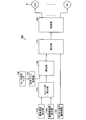
- FIG. 1 is a block diagram illustrating a functional configuration of the torque distribution device according to the embodiment.
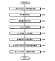
- FIG. 2 is a flowchart showing a procedure of torque distribution processing by the torque distribution device.
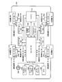
- FIG. 3 is a schematic diagram showing the configuration of the moving body.
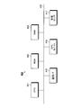
- FIG. 4 is a block diagram illustrating a hardware configuration of the torque distribution device.
- FIG. 5 is a diagram illustrating an example of a motor efficiency map.
- FIG. 6 is a diagram showing the relationship between the slip ratio and the friction coefficient.
- FIG. 7 is a diagram showing the relationship between the rotational speed and the torque in consideration of the slip ratio.
- FIG. 8 is a diagram showing a state where the change curve shown in FIG. 7 is superimposed on the motor efficiency map.
- FIG. 1 is a block diagram illustrating a functional configuration of the torque distribution device according to the embodiment.
- FIG. 2 is a flowchart showing a procedure of torque distribution processing by the torque distribution device.
- FIG. 3 is a schematic diagram showing the configuration of the
- FIG. 9A is a diagram showing a relationship between torque and efficiency that differ for each vehicle body speed (No. 1).
- FIG. 9-2 is a diagram showing a relationship between torque and efficiency that differ for each vehicle body speed (part 2).
- FIG. 10 is a diagram illustrating the relationship between torque and efficiency.
- FIG. 11A is a diagram illustrating a torque-efficiency characteristic specific to a motor (part 1).
- FIG. 11B is a diagram showing a torque-efficiency characteristic specific to the motor (part 2).
- FIG. 11C is a diagram showing a torque-efficiency characteristic specific to the motor (part 3).
- FIG. 12A is a diagram of the characteristics of each wheel in the inverted-U type torque-efficiency characteristics (No. 1).
- FIG. 1 is a diagram showing a relationship between torque and efficiency that differ for each vehicle body speed (No. 1).
- FIG. 9-2 is a diagram showing a relationship between torque and efficiency that differ for each vehicle body speed (part 2).
- FIG. 10 is a diagram illustrating the
- FIG. 12-2 is a diagram of the characteristics of each wheel in the inverted-U torque-efficiency characteristics (part 2).
- FIG. 12-3 is a diagram showing the characteristic of each wheel in the inverted U-type torque-efficiency characteristic (part 3).
- FIG. 12-4 is a diagram of the characteristics of the wheels in the inverted-U torque-efficiency characteristics (part 4).
- FIG. 12-5 is a diagram showing the characteristics of the wheels in the inverted-U torque-efficiency characteristics (No. 5).
- FIG. 12-6 is a diagram showing the characteristics of the wheels in the inverted-U torque-efficiency characteristics (No. 6).
- FIG. 13-1 is a diagram showing the characteristics of each wheel in the ⁇ -type torque-efficiency characteristics (No. 1).
- FIG. 1 is a diagram showing the characteristics of each wheel in the ⁇ -type torque-efficiency characteristics (No. 1).
- FIG. 13-2 is a diagram of the characteristics of each wheel in the ⁇ -type torque-efficiency characteristics (part 2).
- FIG. 13C is a diagram of the characteristics of the wheels in the ⁇ -type torque-efficiency characteristics (part 3).
- FIG. 13-4 is a diagram showing the characteristic of each wheel in the ⁇ -type torque-efficiency characteristics (part 4).
- FIG. 13-5 is a diagram showing the characteristic of each wheel in the ⁇ -type torque-efficiency characteristics (part 5).
- FIG. 13-6 is a diagram showing the characteristics of the respective wheels in the ⁇ -type torque-efficiency characteristics (No. 6).
- FIG. 14A is a diagram of the characteristics of each wheel in a human-type torque-efficiency characteristic (No. 1).
- FIG. 14A is a diagram of the characteristics of each wheel in a human-type torque-efficiency characteristic (No. 1).
- FIG. 13-2 is a diagram of the characteristics of each wheel in the ⁇ -type torque-efficiency characteristics (part 2).
- FIG. 13C is a diagram of the
- FIG. 14-2 is a diagram of the characteristics of each wheel in the human torque-efficiency characteristics (part 2).
- FIG. 14C is a diagram of the characteristics of each wheel in the human-type torque-efficiency characteristics (part 3).
- FIG. 14-4 is a diagram of the characteristics of each wheel in the human torque-efficiency characteristics (part 4).
- FIG. 14-5 is a diagram showing the characteristics of each wheel in the human torque-efficiency characteristics (part 5).
- FIG. 14-6 is a diagram showing the characteristics of each wheel in the human-type torque-efficiency characteristics (No. 6).
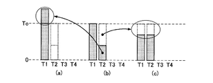
- FIG. 15A is a diagram for explaining torque distribution when there are four drive wheels (part 1).
- FIG. 15-2 is a diagram for explaining torque distribution when there are four drive wheels (part 2).
- FIG. 15A is a diagram for explaining torque distribution when there are four drive wheels (part 2).
- FIG. 15C is a diagram for explaining torque distribution when there are four drive wheels (part 3);
- FIG. 15-4 is a diagram for explaining torque distribution when there are four drive wheels (part 4).
- FIG. 15-5 is a diagram for explaining torque distribution when there are four drive wheels (part 5).
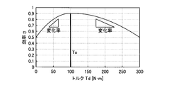
- FIG. 16A is a diagram for explaining a difference in change rate in torque-efficiency characteristics.
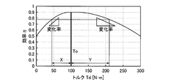
- FIG. 16B is a diagram for explaining the distance from the optimum efficiency torque value in the torque-efficiency characteristic.
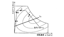
- FIG. 17 is a diagram for explaining dynamic torque distribution according to a running pattern.
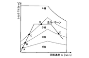
- FIG. 18 is a table showing setting data for the optimum number of drive wheels based on the rotational speed-total torque command value.
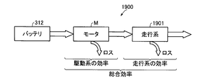
- FIG. 19 is a diagram for explaining the overall efficiency.
- FIG. 19 is a diagram for explaining the overall efficiency.
- FIG. 20 is a diagram showing the relationship between torque and running efficiency when the vertical drag is constant.
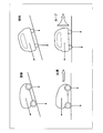
- FIG. 21 is a diagram illustrating a state in which the vertical drag for each drive wheel is different.
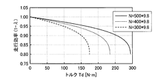
- FIG. 22 is a chart showing torque-running efficiency by vertical drag.
- FIG. 23 is a diagram for explaining the overall efficiency of the entire moving object.
- FIG. 24 is a block diagram of a functional configuration of the torque distribution device according to the second embodiment.
- FIG. 25A is a diagram of a calculation example of the total efficiency (part 1).
- FIG. 25-2 is a diagram of a calculation example of the total efficiency (part 2).
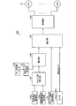
- FIG. 1 is a block diagram illustrating a functional configuration of the torque distribution device according to the embodiment.
- the torque distribution device 100 according to the embodiment uses a motor efficiency map and controls torque distribution for a plurality of drive wheels based on the optimum efficiency torque value on the motor efficiency map.
- the torque distribution device 100 includes an all torque command value acquisition unit 101, a vehicle body speed detection unit 102a, a drive wheel speed detection unit 102b, a slip ratio calculation unit 103, a motor efficiency map 104, and an efficiency map acquisition unit 105. , Calculation unit 106, distribution unit 107, and control unit 108.
- the total torque command value acquisition unit 101 acquires a total torque command value for driving the moving body. That is, all torque command values inputted to drive a plurality of n motors M (M1, M2,... Mn) respectively provided on the drive wheels are acquired. In this embodiment, the plurality of motors M will be described on the assumption that the same type of motor is used.
- the vehicle body speed detection unit 102a detects the speed of the moving body.
- the drive wheel speed detection unit 102b detects the drive wheel speed provided in the moving body.
- the slip ratio calculation unit 103 is described later based on the speed of the moving body detected by the vehicle body speed detection unit 102a and the drive wheel speed (drive wheel rotation speed and tire radius) detected by the drive wheel speed detection unit 102b. Thus, the slip ratio in each drive wheel is calculated.
- the motor efficiency map 104 is a map showing the relationship between the speed and torque in each motor M as shown in FIG. 5 described later. On this map, a substantially linear operation line is shown based on the torque and speed. Can be drawn.
- the efficiency map acquisition unit 105 acquires a motor efficiency map 104 corresponding to the motor M.
- a motor efficiency map prepared in advance by a motor manufacturer or car manufacturer is stored in a memory or the like. For example, a motor efficiency map may be created while the moving body is running.
- the calculation unit 106 Based on the slip ratio calculated by the slip ratio calculation unit 103, the calculation unit 106 creates an efficiency change equation indicating an efficiency value on the operation line indicating the relationship between the rotational speed and the torque, and the efficiency change equation on the operation line. The optimum efficiency torque value at is calculated.
- the distribution unit 107 calculates a torque distribution value for each motor M based on the total torque command value acquired by the total torque command value acquisition unit 101 and the optimum efficiency torque value calculated by the calculation unit 106 as described later. .
- the control unit 108 controls the torque distribution to each motor M based on the torque distribution value calculated by the distribution unit 107.
- FIG. 2 is a flowchart showing a procedure of torque distribution processing by the torque distribution device.
- the total torque command value acquisition unit 101 acquires the total torque command value T input from the accelerator pedal in order to drive a plurality of motors M (M1, M2,... Mn) respectively provided on the drive wheels.
- the vehicle body speed detection unit 102a detects the vehicle body speed of the moving body (step S202), and the drive wheel speed detection unit 102b detects the wheel speed of the drive wheels (step S203).
- the slip ratio calculation unit 103 calculates the slip ratio in the drive wheels using the moving body speed and the drive wheel speed (drive wheel rotation speed and tire radius) (step S204).
- the efficiency map acquisition unit 105 acquires the motor efficiency map 104 corresponding to the motor M (step S205).
- the efficiency value on the operation line indicating the relationship between the rotational speed and the torque.
- An optimum efficiency torque value To in the efficiency change equation on the operating line is calculated (step S206).
- the distribution unit 107 calculates a torque distribution value for each motor M based on the total torque command value T acquired by the total torque command value acquisition unit 101 and the optimum efficiency torque value To calculated by the calculation unit 106. (Step S207).
- the control unit 108 controls the torque distribution to each motor M based on the torque distribution value calculated by the distribution unit 107 (step S208).
- the operation line on the motor efficiency map is linear, but actually, when the torque distribution is changed, the torque of the driving wheel changes, and the rotational speed of the driving wheel changes accordingly. Therefore, under a condition where the vehicle body speed is constant, the operation line on the motor efficiency map is not linear but has an inclination (strictly, a predetermined curve) as shown in FIG.
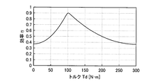
- the efficiency value with respect to the torque value on the operating line can be expressed as a torque-efficiency characteristic. Since the torque-efficiency characteristic is a curve as shown in FIG. 10 described later, the torque with the highest efficiency appears. The torque at which the efficiency is highest is referred to as the optimum efficiency torque value To. Then, using this optimum efficiency torque value To as a reference, all torque command values T are distributed to a plurality of n motors M with a predetermined torque distribution.
- the distribution unit 107 distributes all of the optimal efficiency torque values To only to the torque distribution values of any one of the plurality of n motors, or each of all or some of the motors M. All torque command values T are evenly distributed so that the torque distribution values are closest to the optimum efficiency torque value To.
- the efficiency change equation indicating the efficiency place on the operation line indicating the relationship between the wheel speed and the slip ratio, the rotation speed and the torque is obtained by the following procedure. 1. 1. Detection of current vehicle speed 2. Detection of current driving wheel speed 3. Calculation of slip ratio 4. Detect current torque from motor drive current Calculate the operating line formula (using formula (8) described later) 6). 6. Draw an action line on the efficiency map and obtain multiple points of combinations of torque value and efficiency value along the action line. Creating an efficiency change formula from torque values and efficiency values at multiple points At this time, the accuracy of the approximate formula of the efficiency change formula can be increased as the number of points increases.
- the following procedure is used to create the relationship (6) between the slip ratio and the friction coefficient in the vehicle.
- the current vehicle speed and drive wheel rotation speed are detected to determine the slip ratio ⁇ .
- the ⁇ and ⁇ values of a plurality of points are obtained, and the ⁇ - ⁇ characteristic shown in FIG.
- the torque value is obtained by multiplying a known torque constant by the drive current. In this case, since the tire normally travels without idling, it is possible to detect the ⁇ value and ⁇ value ( ⁇ is 0.2 or less in FIG. 6) in a range not exceeding the peak portion of ⁇ .
- the torque distribution device 100 considers the calculated slip ratio when calculating the optimum efficiency torque value To on the motor efficiency map 104.
- the slip state of the drive wheel with respect to the road surface varies depending on factors such as the speed of the moving body, and more specifically, the rotational speed of the drive wheel.
- the optimal torque distribution when the drive wheels are actually driven can be performed and the motor can be driven in a region where the motor efficiency is high, so that the optimization of the drive system efficiency can be maximized. become.
- the drive system refers to a configuration related to driving of a moving body including a motor and an inverter.
- Example 1 of the present invention will be described below.
- the torque distribution device is applied to a moving body such as a vehicle equipped with an in-wheel type motor that is incorporated in each of four drive wheels and driven independently.
- four motors M1 to M4 are used.
- the motor M a three-phase AC motor or a DC motor can be used.
- the same motor is used for the four drive wheels.
- the number of drive wheels is not limited to four, and the present invention can be applied to two, three, five, or more.
- FIG. 3 is a schematic diagram showing the configuration of the moving body.
- the moving body 300 is a four-wheel drive vehicle having left and right front drive wheels FL and FR and left and right rear drive wheels RL and RR.
- Each of these four drive wheels FL, FR, RL, RR is provided with in-wheel type motors M1 to M4, which are driven independently.
- motors M1 to M4 are each provided with an inverter INV for driving the motor, and each inverter INV drives the motors M1 to M4 based on the control of the controller (ECU) 301. Various information is input to the controller 301, and the motors M1 to M4 are driven as a result of torque distribution.
- Input to the controller 301 includes the following.
- a steering angle is input from the handle 302. From the accelerator pedal 303, the total torque command value is input.
- a brake amount is input from the brake pedal 304.
- a side brake amount is input from the side brake 305.
- a shift position such as R, N, and D is input from the gear 306.
- Each of the driving wheels FL, FR, RL, RR is provided with sensors 307a to 307d for detecting the rotational speed V, and the rotational speeds Vfl, Vfr, Vrl, Vrr of the driving wheels FL, FR, RL, RR are provided. Is input to the controller 301.
- Each of the driving wheels FL, FR, RL, and RR is provided with sensors 308a to 308d that detect the vertical drag N that the tire receives from the ground, and the vertical drag Nfl of each of the driving wheels FL, FR, RL, and RR, Nfr, Nrl, and Nrr are input to the controller 301.
- the moving body 300 is provided with an acceleration sensor 309, and the detected acceleration is input to the controller 301. Further, the moving body 300 is provided with a yaw rate sensor 310, and the detected yaw rate is input to the controller 301.
- the controller 301 drives each driving wheel FL, FR, RL, RR based on the above input.
- a control signal for driving is appropriately distributed to each driving wheel FL, FR, RL, RR, and is supplied to each of the motors M1 to M4 via the inverter INV.
- the battery 312 supplies power to the entire moving body 300. In particular, it becomes a drive source for driving the motors M1 to M4 of the drive wheels FL, FR, RL, RR via the inverter INV.
- a secondary battery such as nickel hydride or lithium ion, a fuel cell, or the like is applied.
- the inverter INV can convert the AC voltage generated by the motors M1 to M4 into a DC voltage when the moving body 300 is regenerated, and supply the converted DC voltage to the battery 312.
- the regeneration indicates power generation by operating the brake pedal 304 by a driver who operates the moving body 300 or power generation by relaxing the depression of the accelerator pedal 303 during traveling.
- FIG. 4 is a block diagram illustrating a hardware configuration of the torque distribution device.
- the torque distribution device 400 includes a CPU 401, a ROM 402, a RAM 403, a communication I / F 415, a GPS unit 416, and various sensors 417.
- Each component 401 to 417 is connected by a bus 420.
- the CPU 401 is responsible for overall control of the torque distribution device 400.
- the ROM 402 stores programs such as a boot program and a torque distribution program, and can hold a motor efficiency map and the like.
- the RAM 403 is used as a work area for the CPU 401. That is, the CPU 401 controls the entire torque distribution device 400 by executing a program recorded in the ROM 402 while using the RAM 403 as a work area.
- the communication I / F 415 is connected to a network via wireless and functions as an interface between the torque distribution device 400 and the CPU 401.
- the communication network functioning as a network includes a public line network, a mobile phone network, DSRC (Dedicated Short Range Communication), LAN, WAN, and the like.
- the communication I / F 415 is, for example, a public line connection module, an ETC unit, an FM tuner, a VICS (Vehicle Information and Communication System) / beacon receiver, or the like.
- the GPS unit 416 receives radio waves from GPS satellites and outputs information indicating the current position of the moving object.
- the output information of the GPS unit 416 is used when the CPU 401 calculates the current position of the moving body together with output values of various sensors 417 described later.
- the information indicating the current position is information for specifying one point on the map data, such as latitude / longitude and altitude.
- the communication I / F 415 and the GPS unit 416 are used.
- the various sensors 417 are used for detecting the vehicle body speed and the normal force.
- the vehicle body speed is detected by the following method, for example. 1. 1. Integrate acceleration sensor output. 2. Calculated from the rotational speed of non-driving wheels Calculated from distance traveled per hour by GPS and other position sensors
- a load sensor provided for each tire is used, or is detected by the following method. 1. 1. Calculate the load balance between the front and rear wheels by calculating the displacement of the center of gravity from the acceleration sensor output. 2. Calculate the load balance between the right and left wheels by calculating the deviation of the center of gravity from the output of the yaw rate sensor Calculate the load balance between the front and rear wheels and the right and left wheels by calculating the deviation of the center of gravity from the tilt sensor (gyro) output.
- the calculation unit 106, the distribution unit 107, and the control unit 108 of the torque distribution device 100 illustrated in FIG. 1 use the programs and data recorded in the ROM 402, the RAM 403, and the like in the torque distribution device 400 described above to perform predetermined processing by the CPU 401.
- the function is realized by executing the program and controlling each part in the torque distribution device 400.
- the torque distribution device 400 of the present embodiment performs optimization that maximizes the drive system efficiency. Assuming that the torque applied to each drive wheel is T1, T2, T3, T4 and the efficiency is ⁇ 1, ⁇ 2, ⁇ 3, ⁇ 4, the overall efficiency ⁇ for the four wheels is expressed by the following equation (1).
- FIG. 5 is a diagram illustrating an example of a motor efficiency map.
- the horizontal axis is the rotation speed, and the vertical axis is the torque.
- the following drive wheel selection is considered using the efficiency obtained on the linear operation line C when the vehicle body is at a certain speed shown in FIG. (1) Equal torque drive with 4 wheels (2) Equal torque drive with 2 wheels (3) Drive with only 1 wheel
- the driving torque of the driving wheel means the torque of the motor mounted on the driving wheel.
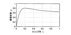
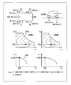
- FIG. 6 is a diagram showing the relationship between the slip ratio and the friction coefficient.
- the horizontal axis represents the slip ratio ⁇
- the vertical axis represents the friction coefficient ⁇ .
- the slip ratio ⁇ and the friction coefficient ⁇ have the relationship shown in FIG. 6 and can be approximated by the following equation (6).
- the friction coefficient ⁇ is the highest when the slip ratio ⁇ is 0.2.
- the slip ratio ⁇ is 1, this corresponds to a state where the driving wheel is idling.
- the slip ratio ⁇ falls within the range of 0 to 0.2, the drive wheels can travel without idling.
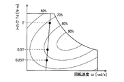
- FIG. 7 is a diagram showing the relationship between the rotational speed and the torque in consideration of the slip ratio. The state which calculated the torque and the rotational speed based on the said formula is shown.
- vertical drag N 400 [kg] ⁇ 9.8 [m / s 2 ], tire radius r: 0.3 [m]
- vehicle speed v 25, 50, 75, 100 [km / h] did.
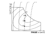
- FIG. 8 is a diagram showing a state where the change curve shown in FIG. 7 is overlaid on the motor efficiency map.
- the horizontal axis represents the rotational speed ⁇ , and the vertical axis represents the torque Td.
- the motor efficiency map shows not only the characteristics of the motor M but also the characteristics including the characteristics (efficiency) of the inverter INV included in the drive system.
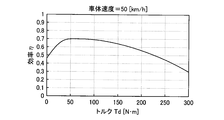
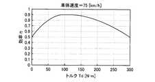
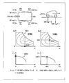
- FIGS. 9-1 and 9-2 are diagrams showing the relationship between torque and efficiency that differ for each vehicle speed.
- FIG. 9A is a torque-efficiency characteristic on the operation line at 50 [km / h]
- FIG. 9-2 is a torque-efficiency characteristic on the operation line at 75 [km / h]. .
- the efficiency ⁇ can be obtained by substituting a value for the torque Td in the above approximate expression.
- the slip ratio ⁇ is defined by the following formula (11).
- Rotational speed of the drive wheel can be calculated using pulse output signals from the resolver, encoder, hall element, etc. of the motor M.
- the speed of the moving body is as follows: 1. Since the slip ratio of the non-driving wheels is almost zero, the speed of the non-driving wheels is detected as the vehicle speed. 2. Obtain the vehicle speed by integrating the output of the acceleration sensor. For example, the position of the vehicle body is detected by a sensor, and the speed is obtained from the moving distance per time.
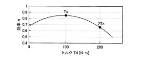
- FIG. 10 is a diagram illustrating the relationship between torque and efficiency. As in FIGS. 9-1 and 9-2, the horizontal axis represents torque and the vertical axis represents efficiency. As shown in FIG. 10, the point with the highest efficiency ⁇ on the operating line is defined as the optimum efficiency torque value To. In addition, the efficiency corresponding to the torque twice the optimum efficiency torque value To on the operation line is expressed as 2To.
- FIGS. 11-1 to 11-3 are diagrams showing torque-efficiency characteristics specific to the motor.
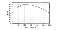
- FIG. 11-1 is an inverted U type
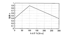
- FIG. 11-2 is a ⁇ type
- FIG. 11-3 is a human type.
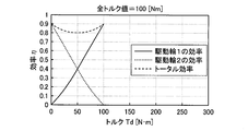
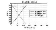
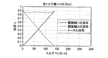
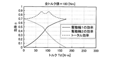
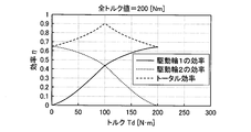
- the efficiency ⁇ when the total torque command value T is distributed by two wheels is based on the above equation (1).
- ⁇ (T1 ⁇ ⁇ 1 + T2 ⁇ ⁇ 2) / T (13) (Torque of driving wheel 1: T1, efficiency at that time: ⁇ 1, torque of driving wheel 2: T2, efficiency at that time: ⁇ 2) It becomes.
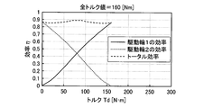
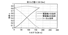
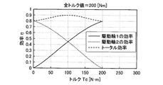
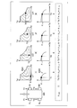
- FIGS. 12-1 to 12-6 are diagrams showing the characteristics of each wheel in the inverted-U type torque-efficiency characteristics.
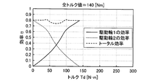
- the total efficiency is a characteristic obtained by substituting into the above equation (13).
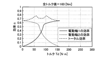
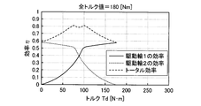
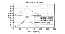
- FIGS. 13-1 to 13-6 are graphs showing the characteristics of the respective wheels in the ⁇ -type torque-efficiency characteristics.
- the total torque command value T is 140 [Nm]
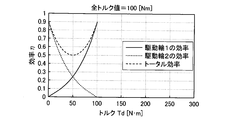
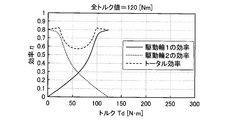
- FIGS. 14-1 to 14-6 are diagrams showing the characteristics of each wheel in the human-type torque-efficiency characteristics.
- the total torque command value T is 120 [Nm]
- the total torque command value T is 140 [Nm]
- the efficiency ⁇ is maximized when (T1, T2)
- the combination that maximizes the efficiency ⁇ is one of the following.
- (T1, T2) (0, T), (T, 0), (To, T-To), (T-To, To), (T / 2, T / 2) (14)
- (To: optimal efficiency torque value) Therefore, even if the curve shape of the torque-efficiency characteristic is any of the types shown in FIGS. 11-1 to 11-3, there is a combination that maximizes the efficiency ⁇ among the combinations of (14). Focused on.
- the combination that maximizes the result of calculating the combination shown in (14) is the torque distribution combination that maximizes the efficiency ⁇ .
- the torque-efficiency characteristic is a complicated curve shape, it may be possible to achieve maximum efficiency other than the combination of (14) above, but if it is other than a complicated characteristic with many inflection points, it is shown in (14) above.
- Some combinations have maximum efficiency. That is, there are an infinite number of combinations of torque distribution, but it is possible to obtain an optimal torque distribution value only by calculating the combination shown in (14) above.
- torque distribution for two wheels has been described as an example, but the same applies to torque distribution for a plurality of drive wheels such as four wheels.
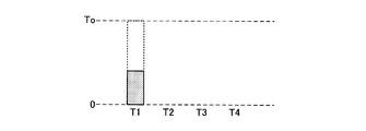
- the distribution unit 107 (1) When the number of motors M is n (n is a natural number), the distribution unit 107 (1) When the total torque command value T is less than the optimum efficiency torque value To, the total torque command value T is distributed to the torque distribution value of one motor M.
- T k-1 ways there are 2k-1 ways.
- T1 To + (Tn ⁇ To) / 1
- the present invention can be applied not only to four-wheel drive but also to torque distribution in moving bodies such as 6-wheel drive and 8-wheel drive.
- the ratio of the efficiency change rate between the lower torque side than the optimum efficiency torque value To and the higher torque side than the optimum efficiency torque value To is used to determine the relationship between the commanded total torque command value T and the optimum efficiency torque value To. Simple torque distribution can be performed.
- FIG. 16A is a diagram for explaining the difference in change rate in the torque-efficiency characteristics.
- the rate of change on the low torque side is twice the rate of change on the high torque side with the optimum efficiency torque value To shown in the figure as the center.
- simple torque distribution in the case where the drive wheels are four wheels is performed as follows (1) to (4).
- 150 [Nm] and 75 [Nm] have the same efficiency
- 128.6 [Nm] and 85.7 [Nm] have the same efficiency
- 120 [Nm] and 90 [Nm] have the same efficiency. It is.
- 2 (To ⁇ To / 4) ⁇ T ⁇ 2 (To + 2To / 7) in the example shown in FIG. 16A, when 75 [Nm] ⁇ 2 ⁇ T ⁇ 128.6 [Nm] ⁇ 2 )
- 3 (To ⁇ To / 7) ⁇ T ⁇ 3 (To + 2To / 10) in the example shown in FIG.
- FIG. 16B is a diagram for explaining the distance from the optimum efficiency torque value in the torque-efficiency characteristic.
- k the number of drive wheels
- X the distance from the optimum efficiency torque value To on the low torque side
- Y the distance from the optimum efficiency torque value To on the high torque side
- a (change rate on the high torque side) ) / (Change rate on the low torque side)
- torque distribution is divided into the following (1) to (3).
- FIG. 17 is a diagram for explaining dynamic torque distribution according to a running pattern.
- the traveling pattern of the moving body is described on the motor efficiency map in which the horizontal axis is the rotation speed and the vertical axis is the torque.
- FIG. 18 is a chart showing setting data for the optimum number of driving wheels based on the rotational speed-total torque command value.
- a table or calculation formula for obtaining the number of drive wheels that provides the best overall efficiency can be created in real time during travel. Optimal torque distribution can be performed.
- FIG. 18 shows the results of the above-described torque distribution algorithm, that is, the number of drive wheels and the torque value of each drive wheel, which are outputs when the motor efficiency map is not held in the memory and the input is speed and torque.
- it may be stored in the memory as a calculation formula.
- the operating point of the rotational speed and the torque can be accurately detected by drawing an operating line having an inclination in consideration of the slip ratio on the motor efficiency map.
- the efficiency calculation by torque distribution can be performed accurately.
- optimal torque distribution can be performed for each drive wheel.
- FIG. 19 is a diagram for explaining the overall efficiency.
- the moving body travels by driving the motor M with the power supplied from the battery 312.
- loss due to copper loss due to the resistance of the coil, iron loss due to eddy current or magnetic hysteresis, or the like occurs.
- the efficiency from the power source to the motor M output is the efficiency of the drive system.
- the moving body that travels by the driving force of the motor M actually has a traveling system 1901 that receives the output of the motor M and travels by rotating the tire. Also in this traveling system 1901, loss due to slip between the tire and the road surface occurs.
- the efficiency from the output of the motor M to the output as traveling power is the efficiency of the traveling system.
- the overall efficiency of the moving body is expressed by the efficiency of these drive systems ⁇ the efficiency of the traveling system.
- the torque distribution described in the first embodiment is related to driving efficiency.
- the second embodiment a configuration that maximizes the overall overall efficiency by improving the efficiency of the traveling system will be described.
- the driving force Fd per driving wheel is expressed by the following equation.
- the slip ratio ⁇ is expressed by the above formula (11). Therefore, the efficiency ⁇ of the traveling system can be expressed using the slip ratio ⁇ .
- ⁇ 1 ⁇ (22)
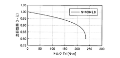
- FIG. 20 is a diagram showing the relationship between torque and running efficiency when the vertical drag is constant.
- the traveling efficiency ⁇ decreases, and the degree of decrease increases as the torque Td increases. That is, when the driving wheel torque Td is increased, the traveling efficiency ⁇ decreases, and when the driving wheel torque Td is decreased, the traveling efficiency ⁇ increases.
- the traveling efficiency ⁇ is not limited to a configuration in which a previously created characteristic map of slip ratio ⁇ friction coefficient ⁇ is held in a memory or the like.
- the vehicle speed at that time is detected by a sensor (or estimated calculation) while the moving body is running, and the slip ratio ⁇ is approximately calculated by detecting the speed of the driving wheel by the sensor. It is also conceivable to use it as a parameter of the running efficiency ⁇ .
- FIG. 21 is a diagram illustrating a state in which the vertical drag for each drive wheel is different.
- the friction coefficient ⁇ changes according to the change in the normal force N from the road surface to the tire.
- the load balance of the moving body changes, and when the vertical drag N of a certain drive wheel decreases, the friction coefficient ⁇ increases.
- the slip ratio ⁇ increases.
- 1- ⁇ shown in the above equation (22) becomes small, and the efficiency ⁇ of the traveling system decreases.
- FIG. 22 is a chart showing torque-running efficiency by vertical drag.
- the greater the vertical drag N the greater the efficiency ⁇ of the traveling system, and the degree of decrease in the efficiency ⁇ of the traveling system associated with the increase in the torque Td is also reduced. Therefore, when the vertical drag N of each drive wheel changes, the drive wheel having a large vertical drag N increases the efficiency ⁇ of the traveling system, and the drive wheel having a small vertical drag N decreases the efficiency ⁇ of the traveling system.
- the driving efficiency can be improved by increasing the torque of the driving wheel having a large load and decreasing the torque of the driving wheel having a small load.
- FIG. 23 is a diagram for explaining the overall efficiency of the entire moving object. All torque command values T are distributed to the drive wheels FL, FR, RL, RR of the moving body 300 by T1, T2, T3, T4. The overall efficiency of the moving body 300 can be obtained by the sum of the torque distribution ratio of each drive wheel FL, FR, RL, RR ⁇ drive efficiency ⁇ d ⁇ running efficiency ⁇ .
- the drive wheel FL in FIG. 23 will be described as an example.
- the drive efficiency ⁇ d 1 is obtained based on the torque T1 distributed to the drive wheel FL and the rotational speed ⁇ 1.
- the running efficiency ⁇ 1 is obtained from the torque T1 distributed to the drive wheels FL.
- the driving efficiencies ⁇ d 2, ⁇ d 3 and ⁇ d 4 and the traveling efficiencies ⁇ 2, ⁇ 3 and ⁇ 4 are obtained for the other driving wheels FR, RL and RR, respectively.
- ⁇ total (T1 / T) ⁇ ⁇ d 1 ⁇ ⁇ 1 + (T2 / T) ⁇ ⁇ d 2 ⁇ ⁇ 2 + (T3 / T) ⁇ ⁇ d 3 ⁇ ⁇ 3 + (T4 / T) ⁇ ⁇ d 4 ⁇ ⁇ 4 (26)
- each drive wheel FL, FR, RL, RR is detected or estimated, and the torque distribution is performed so that the value of the above equation (26) becomes maximum according to the vertical drag, thereby improving the running efficiency. Can be improved.
- FIG. 24 is a block diagram of a functional configuration of the torque distribution device according to the second embodiment. Constituent parts similar to those in FIG.
- the distribution unit 107 receives the vertical drag Nfl, Nfr, Nrl, Nrr of each driving wheel FL, FR, RL, RR from the sensors 308a to 308d (see FIG. 3), and the distribution unit 107 receives each driving wheel.
- the torque distribution ratio for a drive wheel having a large vertical drag N (load) is increased, and the torque distribution ratio for a drive wheel having a small vertical drag N (load) is decreased.
- FIGS. 25A and 25B are diagrams illustrating calculation examples of the total efficiency.
- the vehicle body weight of the moving body 300 is 1600 [kg]
- the total torque command value T is 800 [Nm]
- the load balance moves backward by uphill or acceleration
- the front wheel load is 300 [kg]
- the rear It is assumed that the wheel load is 500 [kg].
- the four wheels are driven at a torque distribution of 200 [Nm] for each driving wheel.
- the overall efficiency ⁇ total is based on the above equation (26).
- the rear wheel torque distribution is 400 [Nm] when two wheels are driven.
- the overall efficiency ⁇ total is based on the above equation (26).
- the driving efficiency and the traveling efficiency can be calculated for each driving wheel. Therefore, the overall efficiency based on the driving efficiency and the traveling efficiency is calculated. Can be calculated.
- the torque distribution algorithm according to the first embodiment selects a combination having the optimum drive system efficiency
- the torque distribution algorithm according to the second embodiment selects the combination having the optimum overall efficiency.
- the operating point of the rotational speed and the torque is accurately detected by drawing an operation line having an inclination in consideration of the slip ratio on the motor efficiency map. be able to.
- the efficiency calculation by torque distribution can be performed accurately.
- optimal torque distribution can be performed for each drive wheel.
- the efficiency of the traveling system can be accurately detected and the overall efficiency can be improved.
- optimal torque distribution that improves the overall efficiency for each drive wheel can be performed.
- the torque distribution amount may be adjusted so as to reduce the left-right torque difference to ensure traveling stability.
- the torque distribution method described in this embodiment can be realized by executing a program prepared in advance on a computer such as a personal computer or a workstation.
- This program is recorded on a computer-readable recording medium such as a hard disk, a flexible disk, a CD-ROM, an MO, and a DVD, and is executed by being read from the recording medium by the computer.
- the program may be a transmission medium that can be distributed via a network such as the Internet.
Abstract
L'invention concerne un dispositif de répartition de couple (100) comportant une unité d'acquisition de valeur totale de commande de couple (101) qui acquiert une valeur totale de commande de couple qui a été entrée; une unité d'acquisition de carte de rendement (105) qui acquiert une carte de rendement du moteur (104) d'un moteur installé; une unité de détection de vitesse du véhicule (102a) qui détecte la vitesse du véhicule; une unité de détection de vitesse de rotation de roue motrice (102b) qui détecte la vitesse de rotation d'une roue motrice; une unité de calcul du rapport de patinage de la roue motrice sur la base du régime du véhicule et de la vitesse de rotation de roue motrice; une unité de calcul (106) qui crée, sur la base du rapport de patinage, une formule de modification de rendement indiquant la valeur de rendement sur une ligne de fonctionnement indiquant la relation entre couple et vitesse de rotation de roue motrice et calcule la valeur de rendement optimal de couple de la formule de modification de rendement sur la ligne de fonctionnement; une unité de répartition (107) qui calcule, sur la base du rapport de patinage, de la valeur totale de commande de couple et de la valeur de rendement optimal de couple, une valeur de répartition de couple pour chaque moteur, de sorte à maximiser le rendement global, ainsi qu'une unité de commande (108) qui régule, sur la base des valeurs de répartition de couple calculées, la répartition de couple propre à chaque moteur.
Priority Applications (4)
| Application Number | Priority Date | Filing Date | Title |
|---|---|---|---|
| EP11858516.5A EP2676830A4 (fr) | 2011-02-18 | 2011-02-18 | Dispositif de répartition de couple, procédé de répartition de couple. procédé et programme de génération de valeur de distribution de couple |
| JP2012502050A JP5096637B1 (ja) | 2011-02-18 | 2011-02-18 | トルク配分装置、トルク配分方法、トルク配分値生成方法およびプログラム |
| PCT/JP2011/053565 WO2012111160A1 (fr) | 2011-02-18 | 2011-02-18 | Dispositif de répartition de couple, procédé de répartition de couple. procédé et programme de génération de valeur de distribution de couple |
| US14/000,019 US9014897B2 (en) | 2011-02-18 | 2011-02-18 | Torque distribution apparatus, torque distribution method, torque distribution value generation method, and program |
Applications Claiming Priority (1)
| Application Number | Priority Date | Filing Date | Title |
|---|---|---|---|
| PCT/JP2011/053565 WO2012111160A1 (fr) | 2011-02-18 | 2011-02-18 | Dispositif de répartition de couple, procédé de répartition de couple. procédé et programme de génération de valeur de distribution de couple |
Publications (1)
| Publication Number | Publication Date |
|---|---|
| WO2012111160A1 true WO2012111160A1 (fr) | 2012-08-23 |
Family
ID=46672120
Family Applications (1)
| Application Number | Title | Priority Date | Filing Date |
|---|---|---|---|
| PCT/JP2011/053565 WO2012111160A1 (fr) | 2011-02-18 | 2011-02-18 | Dispositif de répartition de couple, procédé de répartition de couple. procédé et programme de génération de valeur de distribution de couple |
Country Status (4)
| Country | Link |
|---|---|
| US (1) | US9014897B2 (fr) |
| EP (1) | EP2676830A4 (fr) |
| JP (1) | JP5096637B1 (fr) |
| WO (1) | WO2012111160A1 (fr) |
Cited By (5)
| Publication number | Priority date | Publication date | Assignee | Title |
|---|---|---|---|---|
| WO2015135627A1 (fr) * | 2014-03-11 | 2015-09-17 | Wabco Gmbh & | Procédé de commande de moteurs électriques sur des véhicules hybrides à configuration en série ou des véhicules tout électriques équipés d'au moins deux essieux entraînés séparément |
| CN105882634A (zh) * | 2016-05-13 | 2016-08-24 | 南京理工大学 | 高鲁棒性车轮防滑控制方法、防滑控制系统及车辆 |
| JP2017126163A (ja) * | 2016-01-13 | 2017-07-20 | 株式会社豊田自動織機 | 無人搬送車 |
| CN107310397A (zh) * | 2017-05-18 | 2017-11-03 | 奇瑞汽车股份有限公司 | 一种制动能量回收系统能量回收率的计算方法 |
| CN115489335B (zh) * | 2022-08-31 | 2024-04-12 | 重庆赛力斯凤凰智创科技有限公司 | 基于能量回收的扭矩控制方法、装置、设备和介质 |
Families Citing this family (15)
| Publication number | Priority date | Publication date | Assignee | Title |
|---|---|---|---|---|
| EP2676831A4 (fr) * | 2011-02-18 | 2016-02-17 | Pioneer Corp | Dispositif de répartition de couple, procédé de répartition de couple. procédé et programme de génération de valeur de distribution de couple |
| GB2534347B (en) * | 2014-11-19 | 2019-01-09 | Jaguar Land Rover Ltd | Control system and method of controlling a driveline |
| DE102015000215A1 (de) * | 2015-01-08 | 2016-07-14 | Wabco Gmbh | Verfahren zur Ansteuerung von E-Motoren bei seriellen Hybridfahrzeugen mit mindestens zwei separat angetriebenen Achsen |
| US9866163B2 (en) | 2015-03-16 | 2018-01-09 | Thunder Power New Energy Vehicle Development Company Limited | Method for controlling operating speed and torque of electric motor |
| GB2564645B (en) * | 2017-07-17 | 2019-09-25 | Protean Electric Ltd | A control system for a vehicle |
| US11639114B2 (en) * | 2017-07-21 | 2023-05-02 | Proterra Operating Company, Inc. | Efficiency optimization of multi-motor electric vehicles |
| CN107742013B (zh) * | 2017-09-28 | 2021-10-15 | 北京新能源汽车股份有限公司 | 电动汽车驱动轴寿命计算方法及装置 |
| DE102018212031A1 (de) * | 2018-07-19 | 2020-01-23 | Robert Bosch Gmbh | Verfahren zum Betreiben eines Kraftfahrzeugs, Steuergerät und Kraftfahrzeug |
| CN109532839B (zh) * | 2018-12-05 | 2020-08-25 | 北京长城华冠汽车技术开发有限公司 | 适用于多路况的怠速行驶控制系统、控制方法及汽车 |
| CN110843551B (zh) * | 2019-11-26 | 2021-06-29 | 奇瑞汽车股份有限公司 | 一种四驱扭矩分配方法 |
| CN113715597B (zh) * | 2020-05-21 | 2023-02-03 | 华为数字能源技术有限公司 | 动力驱动系统及车辆 |
| KR20220115736A (ko) | 2021-02-10 | 2022-08-18 | 현대자동차주식회사 | 차량의 모터 제어 시스템 및 그 방법 |
| CN113306409A (zh) * | 2021-06-15 | 2021-08-27 | 南京理工大学 | 基于能量法的分布式驱动电动汽车驱动防滑控制方法 |
| CN114312350B (zh) * | 2022-01-05 | 2023-07-14 | 一汽解放汽车有限公司 | 电机控制方法、装置、计算机设备和存储介质 |
| CN114590131B (zh) * | 2022-01-21 | 2023-09-08 | 北方工业大学 | 制动能量回收控制方法、装置及车辆 |
Citations (10)
| Publication number | Priority date | Publication date | Assignee | Title |
|---|---|---|---|---|
| JP2004120821A (ja) * | 2002-09-24 | 2004-04-15 | Japan Science & Technology Corp | 電気自動車の駆動装置 |
| JP2006180657A (ja) | 2004-12-24 | 2006-07-06 | Nissan Motor Co Ltd | 4輪駆動ハイブリッド車両 |
| JP2006213130A (ja) | 2005-02-02 | 2006-08-17 | Toyota Motor Corp | トルク分配装置 |
| JP2006345677A (ja) | 2005-06-10 | 2006-12-21 | Denso Corp | モータによる車両駆動装置 |
| JP2007037217A (ja) | 2005-07-22 | 2007-02-08 | Nissan Motor Co Ltd | 車両駆動システム |
| JP2007313982A (ja) | 2006-05-24 | 2007-12-06 | Toyota Motor Corp | 四輪駆動式車両の駆動力制御装置 |
| JP2008178216A (ja) * | 2007-01-18 | 2008-07-31 | Hitachi Ltd | 自動車及び自動車の制御装置 |
| JP2008228407A (ja) * | 2007-03-09 | 2008-09-25 | Tokyo Metropolitan Univ | 車両の制駆動制御装置 |
| JP2009159682A (ja) | 2007-12-25 | 2009-07-16 | Toyota Motor Corp | 駆動力制御装置 |
| JP2010115065A (ja) * | 2008-11-07 | 2010-05-20 | Aisin Aw Co Ltd | 走行エネルギー学習装置、方法およびプログラム |
Family Cites Families (13)
| Publication number | Priority date | Publication date | Assignee | Title |
|---|---|---|---|---|
| JP2843339B2 (ja) | 1988-11-09 | 1999-01-06 | アイシン・エィ・ダブリュ株式会社 | 電動車両 |
| JP3879650B2 (ja) * | 2002-10-15 | 2007-02-14 | 日産自動車株式会社 | 車両の制御装置 |
| JP2004254375A (ja) * | 2003-02-18 | 2004-09-09 | Hitachi Unisia Automotive Ltd | 車両の駆動力制御装置 |
| JP4146784B2 (ja) * | 2003-11-18 | 2008-09-10 | 富士重工業株式会社 | ハイブリッド車両の駆動力制御装置 |
| JP4534641B2 (ja) * | 2004-07-16 | 2010-09-01 | トヨタ自動車株式会社 | 車輪のスリップ率演算装置及び車輪の制駆動力制御装置 |
| JP4188348B2 (ja) * | 2005-08-10 | 2008-11-26 | 株式会社日立製作所 | 電動車両の走行制御装置および電動走行制御システム |
| KR100946352B1 (ko) | 2005-11-30 | 2010-03-08 | 도요타 지도샤(주) | 차륜독립구동식 차량의 구동력제어장치 |
| JP4839864B2 (ja) * | 2006-01-31 | 2011-12-21 | トヨタ自動車株式会社 | 車両およびその制御方法並びに制動装置 |
| JP2007282406A (ja) | 2006-04-07 | 2007-10-25 | Tokyo Metropolitan Univ | 自動車の制動力制御システム |
| JP2008167624A (ja) | 2007-01-04 | 2008-07-17 | Toyota Motor Corp | 車両およびその制御方法 |
| WO2008092003A2 (fr) * | 2007-01-25 | 2008-07-31 | Honda Motor Co., Ltd. | Commande de systèmes de véhicule pour améliorer la stabilité |
| JP5012351B2 (ja) * | 2007-09-18 | 2012-08-29 | トヨタ自動車株式会社 | 駆動制御装置 |
| EP2676831A4 (fr) * | 2011-02-18 | 2016-02-17 | Pioneer Corp | Dispositif de répartition de couple, procédé de répartition de couple. procédé et programme de génération de valeur de distribution de couple |
-
2011
- 2011-02-18 EP EP11858516.5A patent/EP2676830A4/fr not_active Withdrawn
- 2011-02-18 US US14/000,019 patent/US9014897B2/en not_active Expired - Fee Related
- 2011-02-18 WO PCT/JP2011/053565 patent/WO2012111160A1/fr active Application Filing
- 2011-02-18 JP JP2012502050A patent/JP5096637B1/ja not_active Expired - Fee Related
Patent Citations (10)
| Publication number | Priority date | Publication date | Assignee | Title |
|---|---|---|---|---|
| JP2004120821A (ja) * | 2002-09-24 | 2004-04-15 | Japan Science & Technology Corp | 電気自動車の駆動装置 |
| JP2006180657A (ja) | 2004-12-24 | 2006-07-06 | Nissan Motor Co Ltd | 4輪駆動ハイブリッド車両 |
| JP2006213130A (ja) | 2005-02-02 | 2006-08-17 | Toyota Motor Corp | トルク分配装置 |
| JP2006345677A (ja) | 2005-06-10 | 2006-12-21 | Denso Corp | モータによる車両駆動装置 |
| JP2007037217A (ja) | 2005-07-22 | 2007-02-08 | Nissan Motor Co Ltd | 車両駆動システム |
| JP2007313982A (ja) | 2006-05-24 | 2007-12-06 | Toyota Motor Corp | 四輪駆動式車両の駆動力制御装置 |
| JP2008178216A (ja) * | 2007-01-18 | 2008-07-31 | Hitachi Ltd | 自動車及び自動車の制御装置 |
| JP2008228407A (ja) * | 2007-03-09 | 2008-09-25 | Tokyo Metropolitan Univ | 車両の制駆動制御装置 |
| JP2009159682A (ja) | 2007-12-25 | 2009-07-16 | Toyota Motor Corp | 駆動力制御装置 |
| JP2010115065A (ja) * | 2008-11-07 | 2010-05-20 | Aisin Aw Co Ltd | 走行エネルギー学習装置、方法およびプログラム |
Non-Patent Citations (1)
| Title |
|---|
| See also references of EP2676830A4 |
Cited By (6)
| Publication number | Priority date | Publication date | Assignee | Title |
|---|---|---|---|---|
| WO2015135627A1 (fr) * | 2014-03-11 | 2015-09-17 | Wabco Gmbh & | Procédé de commande de moteurs électriques sur des véhicules hybrides à configuration en série ou des véhicules tout électriques équipés d'au moins deux essieux entraînés séparément |
| US10086838B2 (en) | 2014-03-11 | 2018-10-02 | Wabco Gmbh | Method for actuating electric motors in serial hybrid vehicles or fully electric vehicles having at least two separately driven axles |
| JP2017126163A (ja) * | 2016-01-13 | 2017-07-20 | 株式会社豊田自動織機 | 無人搬送車 |
| CN105882634A (zh) * | 2016-05-13 | 2016-08-24 | 南京理工大学 | 高鲁棒性车轮防滑控制方法、防滑控制系统及车辆 |
| CN107310397A (zh) * | 2017-05-18 | 2017-11-03 | 奇瑞汽车股份有限公司 | 一种制动能量回收系统能量回收率的计算方法 |
| CN115489335B (zh) * | 2022-08-31 | 2024-04-12 | 重庆赛力斯凤凰智创科技有限公司 | 基于能量回收的扭矩控制方法、装置、设备和介质 |
Also Published As
| Publication number | Publication date |
|---|---|
| US20140018987A1 (en) | 2014-01-16 |
| JPWO2012111160A1 (ja) | 2014-07-03 |
| EP2676830A1 (fr) | 2013-12-25 |
| JP5096637B1 (ja) | 2012-12-12 |
| US9014897B2 (en) | 2015-04-21 |
| EP2676830A4 (fr) | 2016-02-17 |
Similar Documents
| Publication | Publication Date | Title |
|---|---|---|
| JP5096636B1 (ja) | トルク配分装置、トルク配分方法、トルク配分値生成方法およびプログラム | |
| JP5096637B1 (ja) | トルク配分装置、トルク配分方法、トルク配分値生成方法およびプログラム | |
| JP4965751B1 (ja) | トルク配分装置、トルク配分方法、トルク配分値生成方法およびプログラム | |
| JP2012228163A (ja) | トルク配分装置およびトルク配分方法 | |
| EP3078537B1 (fr) | Dispositif et procédé de commande de véhicule électrique | |
| US9073449B2 (en) | Efficiency map generating apparatus, efficiency map generating method, and program | |
| CN100475596C (zh) | 车辆再生制动控制设备及方法 | |
| EP3798044B1 (fr) | Dispositif de commande pour véhicule à moteur électrique et procédé de commande pour véhicule à moteur électrique | |
| JP5251380B2 (ja) | 制駆動制御装置及びそれを備えた車両 | |
| US9045057B2 (en) | Efficiency map generating apparatus, efficiency map generating method, and program | |
| KR102569899B1 (ko) | 전기 모터를 구비하는 차량 및 그를 위한 주행 제어 방법 | |
| EP3251906B1 (fr) | Dispositif et procédé de commande de véhicule | |
| CN114599544B (zh) | 电动车辆的控制方法及电动车辆的控制装置 | |
| KR20150062779A (ko) | 인휠 전기자동차의 휠 토크 제어 시스템 및 방법 | |
| JP2012171616A (ja) | トルク配分装置およびトルク配分方法 | |
| Sumiya et al. | Range extension control system for electric vehicle with active front steering and driving/braking force distribution on curving road | |
| JP5096623B2 (ja) | トルク配分装置およびトルク配分方法 | |
| JP2012175904A (ja) | トルク配分装置およびトルク配分方法 | |
| KR101410451B1 (ko) | 독립 구동형 전기 자동차의 차륜 제어 장치, 방법 및 컴퓨터 판독 가능한 기록 매체 | |
| JP2012191831A (ja) | 効率マップ生成装置および効率マップ生成方法 | |
| US11912136B2 (en) | Control method for electric vehicle and control device for electric vehicle | |
| JP2012191832A (ja) | 効率マップ生成装置および効率マップ生成方法 | |
| Gasbaoui et al. | A novel multi-drive electric vehicle system control based on multi-input multi-output PID controller |
Legal Events
| Date | Code | Title | Description |
|---|---|---|---|
| WWE | Wipo information: entry into national phase |
Ref document number: 2012502050 Country of ref document: JP |
|
| 121 | Ep: the epo has been informed by wipo that ep was designated in this application |
Ref document number: 11858516 Country of ref document: EP Kind code of ref document: A1 |
|
| WWE | Wipo information: entry into national phase |
Ref document number: 2011858516 Country of ref document: EP |
|
| NENP | Non-entry into the national phase |
Ref country code: DE |
|
| WWE | Wipo information: entry into national phase |
Ref document number: 14000019 Country of ref document: US |