WO2012111049A1 - Gear device and drive device - Google Patents
Gear device and drive device Download PDFInfo
- Publication number
- WO2012111049A1 WO2012111049A1 PCT/JP2011/004181 JP2011004181W WO2012111049A1 WO 2012111049 A1 WO2012111049 A1 WO 2012111049A1 JP 2011004181 W JP2011004181 W JP 2011004181W WO 2012111049 A1 WO2012111049 A1 WO 2012111049A1
- Authority
- WO
- WIPO (PCT)
- Prior art keywords
- gear
- input shaft
- brake
- external gear
- teeth
- Prior art date
Links
Images


Classifications
-
- F—MECHANICAL ENGINEERING; LIGHTING; HEATING; WEAPONS; BLASTING
- F16—ENGINEERING ELEMENTS AND UNITS; GENERAL MEASURES FOR PRODUCING AND MAINTAINING EFFECTIVE FUNCTIONING OF MACHINES OR INSTALLATIONS; THERMAL INSULATION IN GENERAL
- F16H—GEARING
- F16H19/00—Gearings comprising essentially only toothed gears or friction members and not capable of conveying indefinitely-continuing rotary motion
- F16H19/08—Gearings comprising essentially only toothed gears or friction members and not capable of conveying indefinitely-continuing rotary motion for interconverting rotary motion and oscillating motion
-
- B—PERFORMING OPERATIONS; TRANSPORTING
- B60—VEHICLES IN GENERAL
- B60K—ARRANGEMENT OR MOUNTING OF PROPULSION UNITS OR OF TRANSMISSIONS IN VEHICLES; ARRANGEMENT OR MOUNTING OF PLURAL DIVERSE PRIME-MOVERS IN VEHICLES; AUXILIARY DRIVES FOR VEHICLES; INSTRUMENTATION OR DASHBOARDS FOR VEHICLES; ARRANGEMENTS IN CONNECTION WITH COOLING, AIR INTAKE, GAS EXHAUST OR FUEL SUPPLY OF PROPULSION UNITS IN VEHICLES
- B60K17/00—Arrangement or mounting of transmissions in vehicles
- B60K17/04—Arrangement or mounting of transmissions in vehicles characterised by arrangement, location, or kind of gearing
- B60K17/043—Transmission unit disposed in on near the vehicle wheel, or between the differential gear unit and the wheel
- B60K17/046—Transmission unit disposed in on near the vehicle wheel, or between the differential gear unit and the wheel with planetary gearing having orbital motion
-
- B—PERFORMING OPERATIONS; TRANSPORTING
- B60—VEHICLES IN GENERAL
- B60K—ARRANGEMENT OR MOUNTING OF PROPULSION UNITS OR OF TRANSMISSIONS IN VEHICLES; ARRANGEMENT OR MOUNTING OF PLURAL DIVERSE PRIME-MOVERS IN VEHICLES; AUXILIARY DRIVES FOR VEHICLES; INSTRUMENTATION OR DASHBOARDS FOR VEHICLES; ARRANGEMENTS IN CONNECTION WITH COOLING, AIR INTAKE, GAS EXHAUST OR FUEL SUPPLY OF PROPULSION UNITS IN VEHICLES
- B60K7/00—Disposition of motor in, or adjacent to, traction wheel
- B60K7/0007—Disposition of motor in, or adjacent to, traction wheel the motor being electric
-
- F—MECHANICAL ENGINEERING; LIGHTING; HEATING; WEAPONS; BLASTING
- F16—ENGINEERING ELEMENTS AND UNITS; GENERAL MEASURES FOR PRODUCING AND MAINTAINING EFFECTIVE FUNCTIONING OF MACHINES OR INSTALLATIONS; THERMAL INSULATION IN GENERAL
- F16H—GEARING
- F16H3/00—Toothed gearings for conveying rotary motion with variable gear ratio or for reversing rotary motion
- F16H3/44—Toothed gearings for conveying rotary motion with variable gear ratio or for reversing rotary motion using gears having orbital motion
-
- B—PERFORMING OPERATIONS; TRANSPORTING
- B60—VEHICLES IN GENERAL
- B60K—ARRANGEMENT OR MOUNTING OF PROPULSION UNITS OR OF TRANSMISSIONS IN VEHICLES; ARRANGEMENT OR MOUNTING OF PLURAL DIVERSE PRIME-MOVERS IN VEHICLES; AUXILIARY DRIVES FOR VEHICLES; INSTRUMENTATION OR DASHBOARDS FOR VEHICLES; ARRANGEMENTS IN CONNECTION WITH COOLING, AIR INTAKE, GAS EXHAUST OR FUEL SUPPLY OF PROPULSION UNITS IN VEHICLES
- B60K7/00—Disposition of motor in, or adjacent to, traction wheel
- B60K2007/0092—Disposition of motor in, or adjacent to, traction wheel the motor axle being coaxial to the wheel axle
-
- F—MECHANICAL ENGINEERING; LIGHTING; HEATING; WEAPONS; BLASTING
- F16—ENGINEERING ELEMENTS AND UNITS; GENERAL MEASURES FOR PRODUCING AND MAINTAINING EFFECTIVE FUNCTIONING OF MACHINES OR INSTALLATIONS; THERMAL INSULATION IN GENERAL
- F16H—GEARING
- F16H1/00—Toothed gearings for conveying rotary motion
- F16H1/28—Toothed gearings for conveying rotary motion with gears having orbital motion
- F16H1/32—Toothed gearings for conveying rotary motion with gears having orbital motion in which the central axis of the gearing lies inside the periphery of an orbital gear
- F16H1/321—Toothed gearings for conveying rotary motion with gears having orbital motion in which the central axis of the gearing lies inside the periphery of an orbital gear the orbital gear being nutating
-
- Y—GENERAL TAGGING OF NEW TECHNOLOGICAL DEVELOPMENTS; GENERAL TAGGING OF CROSS-SECTIONAL TECHNOLOGIES SPANNING OVER SEVERAL SECTIONS OF THE IPC; TECHNICAL SUBJECTS COVERED BY FORMER USPC CROSS-REFERENCE ART COLLECTIONS [XRACs] AND DIGESTS
- Y10—TECHNICAL SUBJECTS COVERED BY FORMER USPC
- Y10T—TECHNICAL SUBJECTS COVERED BY FORMER US CLASSIFICATION
- Y10T74/00—Machine element or mechanism
- Y10T74/18—Mechanical movements
- Y10T74/18568—Reciprocating or oscillating to or from alternating rotary
- Y10T74/188—Reciprocating or oscillating to or from alternating rotary including spur gear
Definitions
- the present invention relates to a gear device configured to mesh with an internal gear while eccentrically swinging an external gear disposed inward of the internal gear, and a drive device including the gear device. .
- a so-called eccentric oscillating gear device is known that includes an eccentric gear that engages in an eccentric oscillating motion and that has an external gear having a smaller number of external teeth than an internal gear.
- the input shaft of the gear device of Patent Document 1 is provided with an eccentric portion, and this eccentric portion is inserted into a central hole formed in the central portion of the external gear via a bearing so as to be rotatable around its axis. ing.
- One end of the crankshaft is rotatably supported in the casing of the gear device, while the other end of the crankshaft is rotatably inserted into an insertion hole formed near the outer periphery of the external gear.
- the input shaft is provided with an inclined shaft portion that extends obliquely with respect to the center line of the eccentric portion.
- a disk is rotatably supported on the inclined shaft portion, and teeth that engage with the teeth on the side surface of the external gear are formed on the side surface of the disk.
- the eccentric oscillating gear device of Patent Documents 1 and 2 has an advantage that a high reduction ratio can be obtained while being compact.
- the eccentric oscillating gear device as a part of a drive system of an electric vehicle, for example. That is, the output of the motor is input to the gear device, and the wheels are driven by the rotational force output from the gear device. As a result, a sufficient driving force can be obtained while using a motor with a small maximum output, so that power consumption can be reduced.
- the speed range that is commonly used is wide. For example, when the vehicle is traveling at a high speed exceeding 100 km / h and when starting acceleration from 0 km / h, the number of rotations of the motor is greatly different, and it is high due to the gear device. It is conceivable that high speed traveling cannot be supported if the reduction ratio remains unchanged.
- the present invention has been made in view of the above points, and an object of the present invention is to change the rotational speed and torque as necessary while utilizing the compact structure which is an advantage of the eccentric oscillating gear device. There is to be able to do it.
- the movement of the rotation preventing portion for preventing the rotation of the external gear is controlled.
- an internal gear an external gear arranged in mesh with the internal gear, and having a different number of teeth from the internal gear, and the external gear.
- An input shaft rotatably inserted into a center hole formed in the gear; and a rotation preventing portion that engages with the external gear to prevent the rotation of the external gear, and the input shaft includes the input shaft.
- An eccentric portion that is eccentric with respect to the shaft center line is inserted into the center hole of the external gear and the input shaft is rotated to rotate the external gear by the rotation prevention portion.
- the rotation preventing portion is formed so that the input shaft is inserted and the input shaft is inserted. It is provided so as to be rotatable around the center line of the shaft, and is provided around the input shaft of the rotation preventing portion.
- the rotation prevention unit rotates integrally with the input shaft
- the rotation prevention unit rotates around the center line of the input shaft. Since the rotation prevention portion and the external gear are engaged, the external gear rotates together with the rotation prevention portion.
- the rotational speed of the external gear is the same as the rotational speed of the input shaft.
- the internal gear rotates at the same speed as the input shaft (the same speed as the rotation speed of the motor or the like), and the rotational force of the motor or the like is output. That is, the input shaft and the internal gear rotate at a constant speed.
- a second invention is characterized by comprising the gear device according to the first invention, a motor that rotationally drives the input shaft, and a control unit that controls the motor, the brake device, and the clutch device. is there.
- the number of teeth of the external gear is set to be smaller than the number of teeth of the internal gear
- the control unit switches the clutch device when switching from the second operation to the first operation. Is set in a non-coupled state, and after adjusting the motor rotation speed so that the rotation speed of the input shaft becomes a rotation speed corresponding to the difference in the number of teeth of the two gears, the brake device is operated. It is characterized by this.
- the gear device acts as a speed reducer.
- the clutch device is disengaged and the rotational speed of the motor is Since the rotation speed of the input shaft after the shift is adjusted, the occurrence of shock and vibration due to the difference in the rotation speed is suppressed when the brake device is subsequently operated to reduce the speed. .
- the number of teeth of the external gear is set to be smaller than the number of teeth of the internal gear, and the control unit switches the brake device when switching from the first operation to the second operation.
- the clutch device After the motor is released, after adjusting the rotational speed of the motor so that the rotational speed of the input shaft becomes a rotational speed corresponding to the difference in the number of teeth of the two gears, the clutch device is configured to be in a coupled state. It is characterized by being.
- the brake device when the first operation, that is, the decelerating operation is changed to the second operation, that is, when the input shaft and the internal gear rotate at a constant speed, the brake device is released, and the motor Since the rotation speed of the input shaft is adjusted so that it becomes the rotation speed of the input shaft after shifting, the occurrence of shock and vibration due to the difference in rotation speed is suppressed when the clutch device is subsequently engaged.
- the first aspect of the invention it is possible to switch between the first operation for swinging the external gear and the second operation for rotating the internal gear at the rotational speed of the input shaft.
- a rotational speed and a torque can be changed as needed.
- this gear apparatus when this gear apparatus is used for an electric vehicle, for example, it can respond from a start to a high speed with a small motor with the highest output, so that energy saving can be achieved.
- the rotation of the motor when switching from the second operation to the first operation, the rotation of the motor so that the rotation speed of the input shaft becomes a rotation speed corresponding to the difference in the number of teeth of the internal gear and the external gear. Since the brake device is operated after adjusting the speed, it is possible to suppress the occurrence of impact and vibration due to the difference in rotational speed between the input shaft and the internal gear.
- FIG. 2 is a cross-sectional view of the drive device according to the first embodiment. It is a figure explaining the use condition of a drive device. It is a block diagram of a drive device.
- FIG. 2 is a view corresponding to FIG. 1 in a state where an input shaft is rotated by 180 °. The input shaft of another structure is shown, (a) is an exploded view, (b) is a front view of a ring, (c) is a partial cross-sectional view of the input shaft.
- FIG. 6 is a diagram corresponding to FIG. 1 according to a first modification of the first embodiment.
- FIG. 6 is a view corresponding to FIG. 1 according to a second modification of the first embodiment.
- FIG. 3 is a view corresponding to FIG.
- FIG. 10 is a view corresponding to FIG. 1 according to a first modification of the second embodiment. It is a side view of the external gear and internal gear concerning the modification 2 of Embodiment 2.
- FIG. FIG. 9 is a partially enlarged view of an external gear and an internal gear according to Modification 3 of Embodiment 2.
- FIG. 10 is a view corresponding to FIG. 1 according to the third embodiment. It is a side view of an external gear. It is a side view of a rocking plate.
- FIG. 4 is a diagram corresponding to FIG. 4 according to the third embodiment.
- FIG. 10 is a view corresponding to FIG. 1 according to a modification of the third embodiment. It is a figure explaining another use condition of a drive device.
- FIG. 10 is a view corresponding to FIG. 1 when the brake device 15 is in a non-brake state according to the fourth embodiment.
- FIG. 10 is a view corresponding to FIG. 1 when the brake device 15 is in a brake state according to the fourth embodiment.
- FIG. 20 is a diagram corresponding to FIG. 19 according to the fifth embodiment.
- FIG. 20 is a view corresponding to FIG. 20 according to the fifth embodiment.
- FIG. 20 is a diagram corresponding to FIG. 19 according to the sixth embodiment.
- FIG. 20 is a view corresponding to FIG. 20 according to the sixth embodiment.
- FIG. 20 is a view corresponding to FIG. 19 according to the seventh embodiment.
- FIG. 20 is a view corresponding to FIG. 20 according to the seventh embodiment.
- FIG. 20 is a view corresponding to FIG. 19 according to the eighth embodiment.
- FIG. 20 is a view corresponding to FIG. 20 according to an eighth embodiment.
- FIG. 20 is a diagram corresponding to FIG. 19 according to the ninth embodiment.
- FIG. 20 is a view corresponding to FIG. 20 according to the ninth embodiment.
- FIG. 20 is a view corresponding to FIG. 19 according to the tenth embodiment.
- FIG. 21 is a view corresponding to FIG. 20 according to the tenth embodiment.
- FIG. 20 is a diagram corresponding to FIG. 19 according to the eleventh embodiment.
- FIG. 21 is a view corresponding to FIG. 20 according to the eleventh embodiment.
- FIG. 20 is a view corresponding to FIG. 19 according to the twelfth embodiment.
- FIG. 20 is a view corresponding to FIG. 19 according to the twelfth embodiment.
- FIG. 21 is a view corresponding to FIG. 20 according to the twelfth embodiment.
- FIG. 20 is a view corresponding to FIG. 19 according to the thirteenth embodiment.
- FIG. 20 is a view corresponding to FIG. 20 according to the thirteenth embodiment.
- FIG. 20 is a view corresponding to FIG. 19 according to the fourteenth embodiment.
- FIG. 20 is a view corresponding to FIG. 20 according to the fourteenth embodiment.
- FIG. 20 is a view corresponding to FIG. 19 according to the fifteenth embodiment.
- FIG. 20 is a view corresponding to FIG. 20 according to the fifteenth embodiment.
- FIG. 20 is a view corresponding to FIG. 19 according to the sixteenth embodiment.
- FIG. 20 is a view corresponding to FIG. 19 according to the seventeenth embodiment.
- FIG. 20 is a view corresponding to FIG. 19 according to the seventeenth embodiment.
- FIG. 20 is a view corresponding to FIG. 19 according to an eighteenth embodiment.
- FIG. 20 is a view corresponding to FIG. 19 according to the nineteenth embodiment.
- FIG. 20 is a view corresponding to FIG. 19 according to the twentieth embodiment.
- FIG. 20 is a view corresponding to FIG. 19 according to the twenty-first embodiment.
- FIG. 20 is a view corresponding to FIG. 19 according to the twenty-second embodiment.
- FIG. 21 is a view corresponding to FIG. 20 according to the twenty-second embodiment.
- FIG. 20 is a view corresponding to FIG. 19 according to the twenty-third embodiment.
- FIG. 20 is a view corresponding to FIG. 20 according to the twenty-third embodiment.
- FIG. 20 is a view corresponding to FIG. 19 according to the twenty-fourth embodiment.
- FIG. 20 is a view corresponding to FIG. 19 according to an eighteenth embodiment.
- FIG. 20 is a view corresponding to FIG. 19 according to the nineteenth embodiment.
- FIG. 20 is
- FIG. 21 is a view corresponding to FIG. 20 according to a twenty-fourth embodiment.
- FIG. 20 is a view corresponding to FIG. 19 according to a twenty-fifth embodiment.
- FIG. 20 is a view corresponding to FIG. 20 according to a twenty-fifth embodiment.
- FIG. 20 is a view corresponding to FIG. 19 according to a twenty-sixth embodiment.
- FIG. 20 is a view corresponding to FIG. 20 according to a twenty-sixth embodiment.
- FIG. 20 is a view corresponding to FIG. 19 according to a twenty-seventh embodiment.
- FIG. 20 is a view corresponding to FIG. 20 according to a twenty-seventh embodiment.
- FIG. 20 is a view corresponding to FIG. 19 according to the twenty-eighth embodiment.
- FIG. 20 is a view corresponding to FIG. 19 according to the twenty-eighth embodiment.
- FIG. 20 is a view corresponding to FIG. 19 according to the twenty-ninth embodiment.
- FIG. 20 is a view corresponding to FIG. 19 according to the thirtieth embodiment.
- FIG. 20 is a view corresponding to FIG. 19 according to the thirty-first embodiment.
- FIG. 65 is a cross-sectional view taken along line AA in FIG. 64.
- FIG. 20 is a view corresponding to FIG. 19 according to the thirty-second embodiment.
- FIG. 67 is a sectional view taken along line BB in FIG. 66.
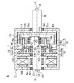
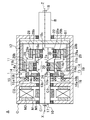
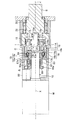
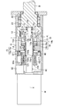
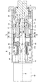
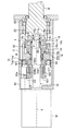
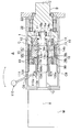
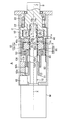
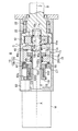
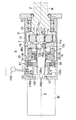
- FIG. 1 is a cross-sectional view of a drive device A including a gear device 1 according to a first embodiment of the present invention.
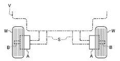
- the drive device A is an in-wheel motor that is used as a part of the drive system of the electric vehicle V and is disposed in the wheel W.
- the output shaft B constituting a part of the gear device 1 is connected to the wheel W by bolts and nuts (not shown), while the casing C of the driving device A is attached to the vehicle body via the suspension device S, for example. It has been.
- the drive device A includes a motor M and a control device (control unit) 2 as shown in FIG. 3 in addition to the gear device 1 and the casing C.
- the gear device 1 in addition to the output shaft B, the gear device 1 includes an input shaft 10, an external gear 11 that moves eccentrically, an internal gear 12 that is fixed to the output shaft B, and an external gear.
- a rotation prevention plate 13 and a crank pin 14 for preventing rotation of the gear 11, a brake device 15, and a clutch device 16 are provided.
- the structure for preventing the rotation of the external gear 11 in the gear device 1 of Embodiment 1 is substantially the same as the structure disclosed in Japanese Utility Model Publication No. 2-45554.
- the input shaft 10 is rotatably supported by the casing C via bearings C1 and C1.
- An eccentric portion 10 a is provided on one end side of the input shaft 10.
- the eccentric portion 10 a is formed in a cylindrical shape having a center line Y that is eccentric by a predetermined amount in the radial direction with respect to the center line X of the input shaft 10.
- the eccentric portion 10 a is accommodated on one end side in the casing C.
- the amount of eccentricity of the eccentric portion 10a may be set by setting the number of teeth of the external gear 11 and the internal gear 12 or the like.
- the input shaft 10 is provided with an input encoder 17 that detects the rotational speed of the input shaft 10. As shown in FIG. 3, the input side encoder 17 is connected to the control device 2, and a signal output from the input side encoder 17 is input to the control device 2.
- the output shaft B protrudes to the outside of the casing C through the wall portion on the other end side of the casing C.
- the output shaft B is rotatably supported via a bearing 22 with respect to the wall portion of the casing C.
- the center line Z of the output shaft B coincides with the center line X of the input shaft 10.
- the output shaft B is provided with an output encoder 18 that detects the rotational speed of the output shaft B. As shown in FIG. 3, the output encoder 18 is connected to the control device 2.
- the wheel W is fixed to the portion of the output shaft B that protrudes outside the casing C.
- An extension portion B1 extending in the radial direction is formed in a portion of the output shaft B located in the casing C, and the internal gear 12 is fixed to the extension portion B1 in an integral manner.
- the internal gear 12 is accommodated on one end side in the casing C, is formed in an annular shape as a whole, and has a large number of teeth on the inner peripheral surface.
- the rotation center of the internal gear 12 coincides with the center line Z of the output shaft B.
- the external gear 11 is arranged inside the internal gear 12 so as to mesh with the internal gear 12. That is, a circular center hole 11 a is formed at the center of the external gear 11 so as to penetrate in the thickness direction of the gear 11.
- An eccentric portion 10 a of the input shaft 10 is inserted into the center hole 11 a of the external gear 11.
- Bearings 20 are inserted between the center hole 11a of the external gear 11 and the eccentric portion 10a of the input shaft 10, and the external gear 11 rotates around the center line Y with respect to the eccentric portion 10a. Supported as possible.
- the eccentric amount of the eccentric portion 10a of the input shaft 10 is such that some teeth of the external gear 11 mesh with some teeth of the internal gear 12, and the other teeth of the external gear 11 are other than the internal gear 12. It is set to be in a state away from the teeth.
- the number of teeth of the external gear 11 is set to be smaller than the number of teeth of the internal gear 12.
- the number of teeth of the internal gear 12 is 44 and the number of teeth of the external gear 11 is 43.
- the number of teeth of the external gear 11 and the internal gear 12 can be set arbitrarily.
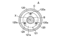
- pin insertion holes 11b into which the crank pins 14 are inserted are formed at substantially equal intervals in the circumferential direction.
- the number of pin insertion holes 11b may not be the same as that of the crank pins 14 and may be formed excessively.
- the number of crankpins 14 is the same as the number of pin insertion holes 11b.
- One side shaft portion 14 a is formed on one end side of the crank pin 14, and this one side shaft portion 14 a is inserted into the pin insertion hole 11 b of the external gear 11.
- the one side shaft portion 14a is rotatable around the center line of the one side shaft portion 14a in a state of being inserted into the pin insertion hole 11b.
- the other side shaft portion 14 b is formed on the other end side of the crankpin 14.
- the amount of eccentricity with respect to the other side shaft portion 14 b of the one side shaft portion 14 a is the same as the amount of eccentricity of the center line Y of the eccentric portion 10 a with respect to the center line X of the input shaft 10.
- the rotation prevention plate 13 is a substantially circular plate.
- a through hole 13a is formed at the center of the rotation prevention plate 13 so as to penetrate in the thickness direction.
- the other end side of the eccentric portion 10a of the input shaft 10 is inserted into the through hole 13a of the rotation prevention plate 13, and the side surface of the rotation prevention plate 13 and the side surface of the external gear 11 are opposed to each other in this state.
- a bearing 24 is provided between the through hole 13 a of the rotation prevention plate 13 and the input shaft 10, and the rotation prevention plate 13 is supported so as to be rotatable around the center line X with respect to the input shaft 10. .
- bearing 24 may be provided as necessary, and may be omitted.
- the number of pin insertion holes 13b may not be the same as the number of crank pins 14, and may be formed extra.
- the other shaft portion 14b of the crank pin 14 is inserted into each pin insertion hole 13b.
- the other side shaft portion 14b is rotatable around the center line of the other side shaft portion 14b in a state of being inserted into the pin insertion hole 13b.
- the rotation preventing portion 19 is engaged with the external gear 11 by the crank pin 14.
- the number of crankpins 14 is 6.
- the number of crankpins 14 is not limited to this.
- the number of crankpins 14 may be 3, and the number is not particularly limited.
- the rotation preventing plate 13 and the crank pin 14 constitute the rotation preventing portion 19 of the present invention.
- the brake device 15 is for prohibiting the movement of the rotation prevention plate 13 and the crankpin 14 around the input shaft 10, and can be switched between a brake state in which the movement is prohibited and a non-brake state in which the movement is permitted. It is like that.
- the brake device 15 is composed of an electromagnetic brake device that operates by electricity, and includes a brake device main body 15a and a brake facing 15b, which are accommodated in a casing C.
- the brake device main body 15a is formed in an annular shape, and is fixed to a brake device fixing portion C2 provided on the inner surface of the casing C with the input shaft 10 inserted therethrough.
- the brake device main body 15 a is positioned so as to face the side surface of the rotation prevention plate 13 opposite to the external gear 11.
- the brake facing 15b is fixed to the outer peripheral portion of the side surface opposite to the external gear 11 of the rotation prevention plate 13 so as to rotate together.
- the brake device main body 15a incorporates an electromagnet and an engaging / disengaging member that engages / disengages with the brake facing 15b.
- the electromagnet is controlled by the control device 2.
- the engagement / disengagement member moves in a direction approaching the brake facing 15b when the electromagnet is energized and engages the brake facing 15b (brake state), while moving in a direction away from the brake facing 15b when the electromagnet is not energized. To disengage from the brake facing 15b (brake release state).
- the rotation prevention plate 13 is fixed to the casing C, and the rotation prevention plate 13 and the crankpin 14 rotate around the input shaft 10. It becomes impossible.
- the rotation prevention plate 13 is in a free state (non-fixed state), and the rotation prevention plate 13 and the crank pin 14 can rotate with respect to the casing C.
- the brake device 15 may be, for example, a type using a solenoid, a powder brake device using magnetic powder, or the like other than the electromagnetic brake device. It is also possible to perform control to create a state where the brake device main body 15a and the brake facing 15b are not completely coupled, that is, a so-called half brake state. When switching from one of the brake state and the brake release state to the other, it is preferable to set the half brake state.
- the clutch device 16 is composed of an electromagnetic clutch device that operates by electricity, and includes a clutch device main body 16a and a clutch facing 16b, which are accommodated in a casing C.
- the clutch device main body 16a is formed in an annular shape, and the input shaft 10 is inserted through the clutch device main body 16a.
- the clutch device main body 16a is positioned so as to face the side surface opposite to the external gear 11 of the rotation prevention plate 13.
- the clutch device main body 16a is integrally coupled to the input shaft 10 using a key or the like (not shown).
- the clutch facing 16b is fixed to the inner peripheral portion of the side surface on the opposite side of the external gear 11 of the rotation prevention plate 13 so as to rotate together.
- the clutch device main body 16a contains an electromagnet and an engaging / disengaging member that engages and disengages with the clutch facing 16b, as in the brake device main body 15a.
- the electromagnet is controlled by the control device 2.
- the engagement / disengagement member moves in a direction approaching the clutch facing 16b when the electromagnet is energized and engages the clutch facing 16b.
- the engagement member moves away from the clutch facing 16b. Leave.
- the rotation prevention plate 13 when the electromagnet is energized by the control device 2, the rotation prevention plate 13 is fixed to the input shaft 10, and the rotation prevention plate 13, the crank pin 14 and the input shaft 10 are coupled together in a rotating manner. It becomes a connected state.
- the rotation prevention plate 13 when the electromagnet is deenergized by the control device 2, the rotation prevention plate 13 is in a free state (uncoupled state) with respect to the input shaft 10, and the rotation prevention plate 13 and the crank pin 14 are moved around the input shaft 10. It can be rotated.
- the clutch device 16 may be, for example, a type using a solenoid, a powder clutch device using magnetic powder, or the like other than the electromagnetic clutch device. It is also possible to perform control to create a state where the clutch device main body 16a and the clutch facing 16b are not completely coupled, that is, a so-called half-clutch state. When switching from one of the coupled state and the non-coupled state to the other, it is preferable to enter a half-clutch state.
- the motor M is housed on the other end side in the casing C, and is a hollow type motor including a rotor M1 and a stator M2.
- the inner peripheral surface of the rotor M2 is fixed to the outer peripheral surface on the other end side of the input shaft 10.
- the outer peripheral surface of the stator M2 is fixed to the inner peripheral surface of the casing C.
- the motor M is connected to the control device 2, and the control device 2 switches the rotation direction and changes the rotation speed.
- the motor M is a small and power-saving motor having a maximum output of about 1/5 to 1/4 of a motor (maximum output 60 kW to 120 kW) generally used in a passenger car type electric vehicle.
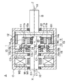
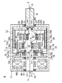
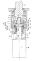
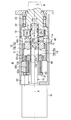
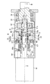
- FIG. 4 shows a state in which the input shaft 10 is rotated 180 ° from the state shown in FIG.
- the internal gear 12 is moved by one swinging motion of the external gear 11. Rotates by an angle corresponding to one tooth. That is, in this embodiment, since the number of teeth of the internal gear 12 is 44, when the external gear 11 rotates 44 times, the internal gear 12 rotates once, and a high reduction ratio of 1:44 is obtained. can get.
- the motor 15 when the motor 15 is rotated with the brake device 15 in the non-brake state and the clutch device 16 in the connected state, the motor M rotates at a constant speed (second operation) without being decelerated or increased. ) That is, the rotation prevention plate 13 can be rotated by setting the brake device 15 to the non-brake state. Further, the rotation prevention plate 13 is coupled to the input shaft 10 by bringing the clutch device 16 into the coupled state.
- the rotation prevention plate 13 rotates at a constant speed with the input shaft 10 and is engaged and integrated through the rotation prevention plate 13 and the crank pin 14.
- the external gear 11 is also rotated at the same speed as the input shaft 10. Since the external gear 11 meshes with the internal gear 12, the internal gear 12 rotates at the same speed as the external gear 11.
- the control device 2 has been conventionally used as a control device for an electric vehicle, and incorporates a known microcomputer or the like, and is configured to control the motor M by a known motor control method.
- the control device 2 is configured to receive at least the driver's accelerator pedal operation amount, vehicle speed, shift lever operation signal, and the like.
- the control device 2 controls the brake device 15, the clutch device 16, and the motor M based on signals input from the accelerator pedal operation amount, the vehicle speed, the input side encoder 17, the output side encoder 18, and the like.
- the brake device 15 When the vehicle speed increases and exceeds 60 km / h, the brake device 15 is brought into a non-brake state, while the clutch device 16 is brought into a coupled state for constant speed operation.
- the timing at which the brake device 15 is brought into the non-brake state and the clutch device 16 is brought into the coupled state is not limited to 60 km / h, and may be, for example, 50 km / h or 80 km / h. Further, at this time, a half brake state or a half clutch state can also be set, whereby an impact generated when the brake device 15 or the clutch device 16 is operated can be suppressed.
- the following control is performed. Before changing the clutch device 16 from the non-engaged state to the engaged state, the brake device 15 is brought into the non-brake state. Then, after the rotational speed of the motor M is lowered so that the rotational speed of the input shaft 10 becomes the rotational speed at the constant speed operation, the clutch device 16 is brought into a coupled state.
- the rotation speed of the input shaft 10 corresponds to the difference in the number of teeth of the two gears 11 and 12 after the brake device 15 is in the non-brake state.
- the clutch device 16 is configured to be in a coupled state.
- the rotation speed of the motor M is adjusted based on the rotation speed of the input shaft 10 and the rotation speed of the output shaft B obtained from the signals of the input side encoder 17 and the output side encoder 18. Note that the adjustment control of the rotational speed of the motor M at the time of switching from the deceleration operation to the constant speed operation is not essential and may not be performed.
- the operation is switched from the constant speed operation to the deceleration operation.
- the following control is performed.
- the clutch device 16 is set to the non-coupled state. Then, after increasing the rotational speed of the motor M so that the rotational speed of the input shaft 10 becomes the rotational speed during the deceleration operation, the brake device 15 is put into a brake state.
- the rotation speed of the input shaft 10 corresponds to the difference in the number of teeth of the two gears 11 and 12 after the clutch device 16 is brought into a non-coupled state. After adjusting the rotational speed of the motor M so as to become, the brake device 15 is operated.
- the rotation speed of the motor M is adjusted based on the rotation speed of the input shaft 10 and the rotation speed of the output shaft B obtained from the signals of the input side encoder 17 and the output side encoder 18.
- a half brake state or a half clutch state can be set. Note that the adjustment control of the rotational speed of the motor M at the time of switching from the constant speed operation to the deceleration operation is not essential and may not be performed.
- the first embodiment it is possible to switch between the deceleration operation in which the external gear 11 is swung and the constant speed operation in which the external gear 11 is rotated at the rotational speed of the input shaft 10. Therefore, when the internal gear 12 is rotated at a speed corresponding to the difference in the number of teeth between the internal gear 12 and the external gear 11 and the rotational force of the motor M is output, the internal gear is output at the same speed as the input shaft 10. Both the operation of rotating the gear 12 and outputting it can be performed.
- the rotation speed of the motor M is adjusted so that the rotation speed of the input shaft 10 becomes a rotation speed corresponding to the difference in the number of teeth of the internal gear 12 and the external gear 11. Then, since the brake device 15 is operated to perform the deceleration operation, it is possible to suppress the occurrence of impact and vibration due to the difference in rotational speed.
- the input shaft 10 is made into the integrally molded product, you may comprise not only this but combining several components as shown in FIG. 5, for example. That is, in the structure shown in FIG. 5, the input shaft 10 includes the ring 3 and the bar 4 as shown in FIG. The bar 4 has no eccentric portion, and the ring 3 forms an eccentric portion 10a (see FIG. 5C).
- the hole 3 a of the ring 3 has a circular cross section that substantially matches the outer diameter of the bar 4.
- the center of the outer circle of the ring 3 is eccentric by a predetermined amount in the radial direction with respect to the center of the hole 3a.
- the input shaft 10 which has the eccentric part 10a is comprised by inserting and fixing the bar 4 to the hole 3a of the ring 3. As shown in FIG.
- the member (ring 3) which comprises the eccentric part 10a, and the member (bar 4) which comprises the main-body part of the input shaft 10 into another member, improving the precision of the input shaft 10, Cost can be reduced. That is, in general, it is difficult to integrally mold a shaft having an eccentric part in a part with high accuracy, which is very expensive.
- the bar 4 having no eccentric portion can be formed at low cost and with high accuracy, and the ring 3 can also be formed at low cost and with high accuracy since it has a simple shape.
- only the ring 3 can be changed to share the bar 4, or only the bar 4 can be changed to share the ring 3.
- the rotation prevention plate 13 may be moved in the direction of the center line X of the input shaft 10 to switch between the operation of the brake device 15 and the operation of the clutch device 16. .
- the brake device main body 15a of the brake device 15 does not operate, and is disposed so as to face the brake facing 15b, and is engaged with and disengaged from the brake facing 15b.
- the clutch device 16 is provided on one end side of the casing C with respect to the rotation prevention plate 13, the clutch device main body 16 a is fixed to the input shaft 10 so as to rotate integrally, and the clutch facing 16 b is an external tooth of the rotation prevention plate 13. It is fixed to the side surface on the gear 11 side so as to rotate together.
- the clutch device main body 16a also does not operate, and is disposed so as to face the clutch facing 16b and engages / disengages with the clutch facing 16b.
- the brake device main body 15a and the clutch device main body 16a can both be separated from the brake facing 15b and the clutch clutch facing 16b of the rotation preventing plate 13 as shown in the figure. Is arranged.
- the rotation prevention plate 13 is supported by the input shaft 10 so as to be slidable in the center line X direction of the input shaft 10. Due to the movement of the rotation prevention plate 13 in the direction of the center line X, the other side shaft portion 14 b of the crank pin 14 slides in the pin insertion hole 13 b of the rotation prevention plate 13.
- the rotation prevention plate 13 is operated from the outside of the casing C.
- a ball bearing 75 is fitted on the outer periphery of the rotation prevention plate 13.
- An inner ring of the ball bearing 75 is fixed to the outer peripheral portion of the rotation prevention plate 13.
- An operation unit 76 is fixed to the outer ring of the ball bearing 75.
- the operation portion 76 protrudes out of the casing C through a through hole C3 formed in the peripheral wall portion of the casing C.
- An actuator (not shown) controlled by the control device 2 is connected to the operation unit 76, and the actuator is operated in the left-right direction (the direction indicated by the arrow) in FIG.
- the rotation prevention plate 13 moves to the right, the brake device main body 15a and the brake facing 15b are separated, and the clutch device main body 16a and the clutch facing 16b are in contact with each other.
- the operation unit 76 is operated to the left in FIG. 6, the rotation prevention plate 13 moves to the left, the brake device main body 15a and the brake facing 15b come into contact with each other, and the clutch device main body 16a and the clutch facing 16b are engaged. Leave.
- the operation unit 76 is stopped at an intermediate position in the left-right direction, both the brake device main body 15a and the clutch device main body 16a are separated from the brake facing 15b and the clutch facing 16b.
- the speed can be changed by operating the operation unit 76.
- a half-brake state can be created in the brake device main body 15a depending on the position of the operation unit 76, and similarly, a half-clutch state can be created in the clutch device 16.
- the operation unit 76 may be manually operated by an occupant.
- the wheel W may be fixed to the internal gear 12 as in Modification 2 shown in FIG.
- the output shaft B is omitted, and although not shown, the output-side encoder can be provided on the internal gear 12 or the wheel W.
- a bearing 77 is fitted on the outer peripheral portion of the external gear 11 and is rotatably supported by the casing C via the bearing 77.
- the output shaft B can be omitted and the internal gear 12 can be positioned inside the wheel W, so that the driving device A can be made compact.
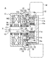
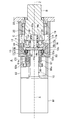
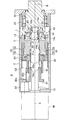
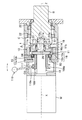
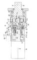
- FIG. 8 is a cross-sectional view of the driving device A according to the second embodiment of the present invention.
- the driving device A of the second embodiment is different from that of the first embodiment in that it includes a balancer plate 28 and a balancer plate driving crank pin 29, and other parts are the same as those of the first embodiment.
- a different part from Embodiment 1 is demonstrated in detail.
- a balancer plate mounting eccentric portion 10c is provided on one end side of the eccentric portion 10a of the input shaft 10.
- the eccentricity of the balancer plate mounting eccentric portion 10c with respect to the input shaft 10 is set to be the same as the eccentricity of the eccentric portion 10a with respect to the input shaft 10.
- the eccentric direction of the balancer plate mounting eccentric portion 10c with respect to the input shaft 10 is opposite to the eccentric direction of the eccentric portion 10a with respect to the input shaft 10 in the radial direction.
- the balancer plate 28 has the same structure as the external gear 11. That is, the balancer plate 28 has a center hole 28a and a pin insertion hole 28b into which the balancer plate driving crank pin 29 is inserted. The balancer plate 28 has the same tooth as the external gear 11 on the outer peripheral surface. Is provided.
- One end shaft portion 29 a is formed on one end side of the balancer plate driving crank pin 29, and this one side shaft portion 29 a is inserted into the pin insertion hole 28 b of the balancer plate 28.
- the one side shaft portion 29a is rotatable around the center line of the one side shaft portion 29a while being inserted into the pin insertion hole 28b.
- the other side shaft portion 29 b is formed on the other end side of the crankpin 29.
- the amount of eccentricity of the one side shaft portion 29a with respect to the other side shaft portion 29b is twice the amount of eccentricity of the center line Y of the eccentric portion 10a with respect to the center line X of the input shaft 10, and the balance between the center line Y of the eccentric portion 10a and the balancer. It is the same as the radial distance from the center line of the plate mounting eccentric portion 10c.
- the other side shaft portion 29 b of the balancer plate driving crank pin 29 is inserted into the pin insertion hole 11 b of the external gear 11.
- the other side shaft portion 29b is rotatable around the center line of the other side shaft portion 29b while being inserted into the pin insertion hole 11b.
- the balancer plate mounting eccentric portion 10c is inserted into the center hole 28a of the balancer plate 28.
- a bearing 30 is provided between the center hole 28a of the balancer plate 28 and the balancer plate mounting eccentric portion 10c, and the balancer plate 28 is rotatable with respect to the balancer plate mounting eccentric portion 10c.
- the teeth of the balancer plate 28 mesh with the teeth of the internal gear 12. Since the eccentric portion 10c for mounting the balancer plate is eccentric in the opposite direction to the eccentric portion 10a, the portion of the internal gear 12 where the teeth of the balancer plate 28 mesh is opposite to the portion of the external gear 11 which meshes with the center line therebetween. become.
- the balancer plate 28 does not necessarily have to mesh with the internal gear 12.
- a friction material having a high friction coefficient that contacts the balancer plate 28 is provided on the internal gear 12, and the friction material allows the balancer plate 28 to be in contact with the balancer plate 28.
- the rotation may be prevented, or conversely, a friction material that contacts the internal gear 12 may be provided on the balancer plate 28, and the rotation of the balancer plate 28 may be prevented by this friction material.
- the balancer plate 28 since the balancer plate 28 is always positioned opposite to the external gear 11 in the radial direction, it acts as a counterweight, and the vibration due to the eccentric oscillating motion of the external gear 11 is canceled out. .
- a support shaft portion 10 f extending on the same line as the center line X of the input shaft 10 is provided at one end portion of the input shaft 10.
- a receiving hole B ⁇ b> 2 is provided on the same line as the center line X of the input shaft 10 at a portion of the output shaft B facing the one end portion of the input shaft 10.
- the support shaft portion 10f of the input shaft 10 is inserted into the receiving hole B2.
- a bearing 31 is provided between the receiving hole B2 and the support shaft portion 10f, and the support shaft portion 10f is supported so as to be rotatable relative to the output shaft B.
- the support structure at one end of the input shaft 10 according to this modification can also be applied to the driving device A of the first embodiment.
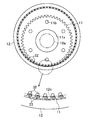
- a roller 32 that functions as a tooth may be provided at a tooth formation portion of the internal gear 12.
- the roller 32 is supported with respect to the main body portion of the internal gear 12 by a support shaft 33 extending in parallel with the rotation center line of the internal gear 12, and can rotate around the support shaft 33.
- the support shaft 33 is attached to a support wall 12 c formed on the inner surface of the internal gear 12.
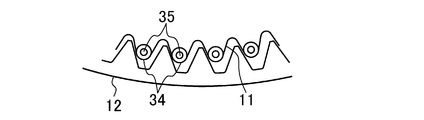
- a roller 34 that functions as a tooth may be provided at a tooth formation portion of the external gear 11.
- the roller 34 is supported with respect to the main body portion of the external gear 11 by a support shaft 35 extending parallel to the rotation center line of the external gear 11, and can rotate around the support shaft 35.
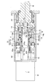
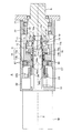
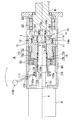
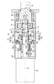
- FIG. 12 shows a driving device A according to Embodiment 3 of the present invention.
- the driving device A of the third embodiment is different from that of the first embodiment in that the structure of the rotation preventing portion is the structure disclosed in Japanese Patent Application Laid-Open No. 2010-84907. Same as 1.
- the structure of the rotation preventing portion is the structure disclosed in Japanese Patent Application Laid-Open No. 2010-84907. Same as 1.
- a different part from Embodiment 1 is demonstrated in detail.
- the gear device 1 according to the second embodiment includes the swing plate 40 instead of omitting the crank pin 14.
- An inclined shaft portion 10b extending obliquely with respect to the center line X of the input shaft 10 is formed on the other end side (left side in FIG. 12) of the eccentric portion 10a of the input shaft 10.
- a plurality of teeth 11 e are continuously formed in the circumferential direction on the outer peripheral portion of the side surface of the external gear 11 on the side of the rotation prevention plate 13.
- a plurality of teeth 13 c are continuously formed in the circumferential direction on the outer peripheral portion of the side surface of the rotation prevention plate 13 on the external gear 11 side.
- the rotation prevention plate 13 is supported by the input shaft 10 so as not to move in the direction of the center line X of the input shaft 10.
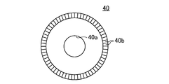
- the swing plate 40 is disposed between the external gear 11 and the rotation prevention plate 13.
- the swing plate 40 has an annular shape having a center hole 40a.
- a plurality of teeth 40 b that mesh with the teeth 11 e of the external gear 11 are formed continuously in the circumferential direction on the outer peripheral portion of the side surface of the rocking plate 40 on the external gear 11 side.
- a plurality of teeth 40c (shown in FIG. 12) that mesh with the teeth 13c of the rotation prevention plate 13 are formed continuously in the circumferential direction on the outer peripheral portion of the side surface of the swing plate 40 on the rotation prevention plate 13 side.
- the inclined shaft portion 10b of the input shaft 10 is rotatably inserted into the center hole 40a of the swing plate 40. Therefore, the swing plate 40 is supported by the input shaft 10 in a state where the center line of the swing plate 40 coincides with the center line of the inclined shaft portion 10b.
- the rocking plate 40 has a part in the circumferential direction close to the external gear 11, and a portion on the opposite side of the central hole 40 a from the adjacent portion is farthest from the external gear 11. It is inclined with respect to the external gear 11.
- the teeth 40b, 40b,... Of the oscillating plate 40 only the tooth 40b near the external gear 11 meshes with the teeth 11e of the external gear 11, so that the oscillating plate 40 and the external gear are engaged. 11 is engaged.
- the swing plate 40 is supported from the opposite side to the external gear 11 by the rotation prevention plate 13. And only the tooth 40c of the part close
- the swing plate 40 When the swing plate 40 is assembled to the input shaft 10, the swing plate 40 may be structured to be divided in the radial direction.
- the operation of the driving device A configured as described above will be described.
- the brake device 15 is brought into the brake state and the clutch device 16 is brought into the non-coupled state and the motor M is rotated
- the speed reduction operation is performed in which the rotation speed of the motor M is reduced by the gear device 1 and output. That is, the rotation prevention plate 13 is fixed to the casing C by setting the brake device 15 to the brake state.
- the rotation prevention plate 13 is free with respect to the input shaft 10 by setting the clutch device 16 to the non-coupled state.
- the teeth 40b of the rocking plate 40 mesh with the teeth 11e of the external gear 11, the rocking plate 40 and the external gear 11 are integrated with each other and cannot rotate relative to each other.
- the teeth 40c of the swing plate 40 and the teeth 13c of the rotation prevention plate 13 are engaged with each other, the swing plate 40 and the rotation prevention plate 13 are also integrated.
- the rotation prevention plate 13 can be rotated by setting the brake device 15 to the non-brake state. Further, the rotation prevention plate 13 is coupled to the input shaft 10 by bringing the clutch device 16 into the coupled state.
- the rotation prevention plate 13 rotates at the same speed as the input shaft 10 and is integrated via the rotation prevention plate 13 and the swing plate 40.
- the external gear 11 also rotates at the same speed as the input shaft 10. Since the external gear 11 meshes with the internal gear 12, the internal gear 12 rotates at the same speed as the external gear 11.
- the control device 2 controls the brake device 15, the clutch device 16 and the motor M as in the first embodiment.
- the rotation speed and the torque can be changed as necessary while having a compact structure.
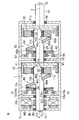
- the first gear device 1 has the structure described above.
- the basic structure of the second gear device 50 is the same as that of the first gear device 1.
- the input shaft 51 of the second gear device 50 is an output shaft of the first gear device 1.
- the input shaft 51 of the second gear device 50 is provided with an eccentric portion 51a and an inclined shaft portion 51b.
- An eccentric portion 51 a is inserted into the center hole 52 a of the external gear 52.
- the external gear 52 is supported via a bearing 53.
- a plurality of teeth 52 b are formed on the side surface of the external gear 52.
- the output shaft 57 is fixed to the internal gear 54.
- the output shaft 57 is supported by the casing C via a bearing 58.
- Teeth 60b are formed on the side surface of the rocking plate 60 on the external gear 11 side, and teeth 60c are formed on the side surface on the rotation prevention plate 62 side.
- the input shaft 51 is inserted into the center hole 62 a of the rotation prevention plate 62.
- teeth 62b are formed on the side surface of the rotation prevention plate 62.
- a brake device 67 and a clutch device 68 are also provided.
- the reduction ratio of the first gear unit 1 is set to 1/6, and the reduction ratio of the second gear unit 50 is set to 1/10.
- the first and second gear devices 1 and 50 are provided in series, so that a multi-stage shift is possible. That is, the brake device 15 of the first gear device 1 is set to the non-brake state, the clutch device 16 is set to the connected state, the brake device 67 of the second gear device 50 is set to the non-brake state, and the clutch device 68 is set to the connected state.
- the motor M is rotated, the output shaft 57 rotates at the rotation speed of the motor M.
- the brake device 15 of the first gear device 1 is set to the brake state
- the clutch device 16 is set to the non-coupled state
- the brake device 67 of the second gear device 50 is set to the non-brake state
- the clutch device 68 is set to the combined state.
- the brake device 15 of the first gear device 1 is brought into a non-brake state
- the clutch device 16 is brought into a coupled state
- the brake device 67 of the second gear device 50 is brought into a brake state
- the clutch device 68 is brought into a non-coupled state.
- the brake device 15 of the first gear device 1 is set to the brake state
- the clutch device 16 is set to the non-coupled state
- the brake device 67 of the second gear device 50 is set to the brake state
- the clutch device 68 is set to the non-coupled state.
- the reduction ratio of the first gear device 1 may be 1/6
- the reduction ratio of the second gear device 50 may be 1/8
- the reduction ratio of the first gear device 1 may be 1/12
- the second The reduction ratio of the gear device 50 may be 1/16.
- a balancer plate may be provided as in Embodiment 2.
- the driving device A is used as an in-wheel motor.
- the present invention is not limited to this.
- FIG. May be modified and provided on the axle 70.
- the driving device A may be provided so as to drive the propeller shaft 100 as shown in FIG.
- the output of the driving device A is transmitted to the wheels W and W through the propeller shaft 100, the differential gear 101, and the drive shafts 102 and 102.
- the drive device A may be attached to the place where the engine is located, so that an electric vehicle can be easily formed.
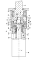
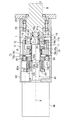
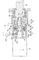
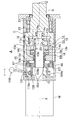
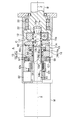
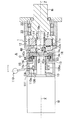
- FIG. 4 is cross-sectional views of the drive device A including the gear device 1 according to the fourth embodiment of the present invention.
- the basic structure of the gear device 1 according to the fourth embodiment is a structure using the crankpin 14 according to the first embodiment.
- the brake device 15 and the clutch device 16 are operated using a screw mechanism.
- the same parts as those in the first embodiment are denoted by the same reference numerals, description thereof will be omitted, and different parts will be described in detail.
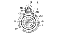
- a male screw member 80 that is formed in an annular shape and has a male screw portion on the outer peripheral surface, a circular female screw member 81 that has a female screw portion that engages with the male screw member 80, and a screw drive motor 82 that drives the female screw member 81.
- the male screw member 80 Inside the male screw member 80, a portion of the input shaft 10 closer to the motor M than the clutch device main body 16a is inserted.
- the male screw member 80 is movable with respect to the input shaft 10 in the center line X direction.
- a facing fixing member 83 is attached to the outer peripheral portion of the male screw member 80 on the clutch device main body 16a side.
- the facing fixing member 83 is formed in an annular shape surrounding the male screw member 80, and is formed on the outer peripheral surface so that a large number of teeth are arranged over the entire periphery.
- the teeth of the facing fixing member 83 mesh with teeth formed in the same manner on the inner peripheral surface of the annular portion 13c extending from the outer peripheral portion of the rotation prevention plate 13 to the motor M side.
- a clutch facing 16b is fixed to a side surface of the facing fixing member 83 on the clutch device main body 16a side, and a brake facing 15b is fixed to a side surface on the brake device main body 15a side.
- the rolling member 84 causes the facing fixing member 83 to be a male screw.
- the member 80 is rotatable around the center line X.
- the facing fixing member 83 and the male screw member 80 are engaged with the rolling member 84 so as not to move relative to each other in the center line X direction.
- a rail engaging portion 80a that engages with a rail C5 fixed to the casing C is provided on the inner peripheral surface of the male screw member 80.
- the rail C5 extends in parallel with the center line X direction. In a state where the rail engaging portion 80a is engaged with the rail C5, the male screw member 80 is prevented from rotating around the center line X and can move only in the direction of the center line X.
- the female screw member 81 is supported by the male screw member 80 and is rotatable around the center line X. On the motor M side of the outer peripheral surface of the female screw member 81, a large number of teeth 81a are formed so as to be arranged over the entire circumference.
- the screw drive motor 82 is fixed to the casing C.
- the output shaft of the screw drive motor 82 is disposed in parallel with the center line X of the input shaft 10.
- a pinion gear 82 a is fixed to the output shaft of the screw drive motor 82.
- the pinion gear 82 a is disposed so as to mesh with the teeth 81 a of the female screw member 81.
- the screw drive motor 82 is controlled by the control device 2 in forward and reverse rotation, rotation start timing, rotation speed, and the like.
- the screw drive motor 82 when the screw drive motor 82 is rotated, the female screw member 81 rotates, and the male screw member 80 moves along the rail C5 in the direction of the center line X depending on the rotation direction of the female screw member 81.
- the brake device 15 when the screw drive motor 82 is rotated so that the male screw member 80 moves in the right direction, the brake device 15 is brought into a non-brake state, and the clutch device 16 is brought into a coupled state.
- the rotation prevention plate 13 is fixed to the input shaft 10.
- a screw drive motor 82 may be provided outside the casing C and the female screw member 81 may be driven by a gear or a belt.
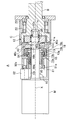
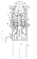
- FIG. 5 are cross-sectional views of the driving device A including the gear device 1 according to the fifth embodiment of the present invention.
- the basic structure of the gear device 1 of the fifth embodiment is a structure using the crank pin 14 of the first embodiment.
- the brake device 15 and the clutch device 16 are operated using a screw mechanism.
- the same parts as those in the first embodiment are denoted by the same reference numerals, description thereof will be omitted, and different parts will be described in detail.
- a male screw member 86 that is formed in an annular shape and has a male screw portion on the outer peripheral surface, a circular female screw member 87 that has a female screw portion that engages with the male screw member 86, and a screw drive motor 82 that drives the male screw member 86.
- the male screw member 86 Inside the male screw member 86, a portion of the input shaft 10 closer to the motor M than the clutch device main body 16a is inserted.
- the male screw member 86 is rotatable around the center line X with respect to the input shaft 10.
- On the motor M side of the outer peripheral surface of the male screw member 86 a large number of teeth 86a are formed so as to be arranged over the entire circumference.
- a facing fixing member 83 similar to that of the fourth embodiment is attached to the outer peripheral portion of the female screw member 87 on the clutch device main body 16a side.
- a rail engaging portion 87a that engages with a rail C5 fixed to the casing C is provided on the outer peripheral surface of the female screw member 87.
- the rail C5 extends parallel to the center line X direction, and the female screw member 87 is prevented from rotating around the center line X and moves only in the center line X direction with the rail engaging portion 87a engaged with the rail C5. It becomes possible.
- the female screw member 87 is supported by the male screw member 86 and is rotatable around the center line X.
- the pinion gear 82 a of the screw drive motor 82 is arranged to mesh with the teeth 86 a of the male screw member 86.
- the screw drive motor 82 when the screw drive motor 82 is rotated, the male screw member 86 is rotated, and the female screw member 87 is moved along the rail C5 in the center line X direction according to the rotation direction of the male screw member 86.
- the brake device 15 when the screw drive motor 82 is rotated so that the female screw member 87 moves in the right direction, the brake device 15 enters the non-brake state, and the clutch device 16 enters the coupled state.
- the rotation prevention plate 13 is fixed to the input shaft 10.
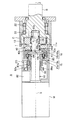
- FIG.23 and FIG.24 is sectional drawing of the drive device A provided with the gear apparatus 1 concerning Embodiment 6 of this invention.
- the basic structure of the gear device 1 of the sixth embodiment is a structure using the crankpin 14 of the first embodiment.
- the brake device 15 and the clutch device 16 are operated using a screw mechanism.
- the same parts as those in the first embodiment are denoted by the same reference numerals, description thereof will be omitted, and different parts will be described in detail.
- a male screw member 88 that is formed in an annular shape and has a male screw portion on the outer peripheral surface, a circular female screw member 89 that has a female screw portion that is screwed into the male screw member 88, and a screw drive motor 82 that drives the female screw member 89.
- the male screw member 88, the female screw member 89, and the screw drive motor 82 are configured similarly to the male screw member 80, the female screw member 81, and the screw drive motor 82 of the fourth embodiment.
- a rail engaging portion 88a that engages with a rail 10d that is formed on the outer peripheral surface of the input shaft 10 and extends in the center line X direction is provided.
- the male screw member 88 can move only in the direction of the center line X in a state where rotation around the center line X is prevented.
- the brake device main body 15 a is formed in an annular shape surrounding the rotation prevention plate 13. A large number of teeth are formed over the entire circumferential direction on the inner peripheral surface of the brake device main body 15a.
- teeth 15b that mesh with the teeth of the brake device main body 15a are formed on the outer peripheral surface of the rotation prevention plate 13.
- a rail engaging portion 90 that engages with a rail C6 that is formed in the casing C so as to extend in the center line X direction is provided. With the rail engaging portion 90 engaged with the rail C6, the brake device main body 15a is prevented from rotating around the center line X and can move in the center line X direction.
- a rolling member 93 similar to the rolling member 84 of the fourth embodiment is provided between the outer peripheral surface of the male screw member 88 and the inner peripheral surface of the brake device main body 15a.
- the male screw member 88 and the brake device main body 15a are engaged with the rolling member 93 so as not to move relative to each other in the center line X direction.
- the clutch device main body 16 a is fixed to the side surface of the rotation prevention plate 13.
- the clutch facing 16b is fixed to a surface corresponding to the side surface of the rotation prevention plate 13 in the male screw member 88.
- FIG. 7 is cross-sectional views of the driving device A including the gear device 1 according to the seventh embodiment of the present invention.
- the basic structure of the gear device 1 according to the seventh embodiment is a structure using the crank pin 14 according to the first embodiment.
- the brake device 15 and the clutch device 16 are operated using a screw mechanism.
- the same parts as those in the first embodiment are denoted by the same reference numerals, description thereof will be omitted, and different parts will be described in detail.
- a male screw member 91 that is formed in an annular shape and has a male screw portion on the outer peripheral surface, a circular female screw member 92 that has a female screw portion that engages with the male screw member 91, and a screw drive motor 82 that drives the male screw member 91.
- the male screw member 91, the female screw member 92, and the screw drive motor 82 are configured similarly to the male screw member 86, the female screw member 87, and the screw drive motor 82 of the fifth embodiment.
- the brake device 15 and the clutch device 16 of the seventh embodiment are configured in the same manner as in the sixth embodiment.
- a rail engaging portion 92a that engages with a rail 10d that is formed on the outer peripheral surface of the input shaft 10 and extends in the direction of the center line X.
- a rail engaging portion 92b that engages with a rail C5 fixed to the casing C is provided. In a state where the rail engaging portion 92b is engaged with the rail C5, the female screw member 92 is prevented from rotating around the center line X, and can move only in the direction of the center line X.
- the screw driving motor 82 when the screw driving motor 82 is rotated, the male screw member 91 is rotated, and the female screw member 92 is moved along the rail C5 in the center line X direction according to the rotation direction of the male screw member 91.
- the teeth of the brake device main body 15a are separated from the teeth 15b of the rotation prevention plate 13 in the direction of the center line X.
- the device 15 is in a non-braking state, and the clutch device 16 is in a coupled state.
- the rotation prevention plate 13 is fixed to the input shaft 10.
- FIGS. 8) 27 and 28 are cross-sectional views of the driving device A including the gear device 1 according to the eighth embodiment of the present invention.
- the basic structure of the gear device 1 of the eighth embodiment is a structure using the crankpin 14 of the first embodiment.
- the brake device 15 and the clutch device 16 are operated using a screw mechanism.
- the same parts as those in the first embodiment are denoted by the same reference numerals, description thereof will be omitted, and different parts will be described in detail.
- a male screw member 94 that is formed in an annular shape and has a male screw portion on the outer peripheral surface, a ring-shaped female screw member 95 that has a female screw portion that engages with the male screw member 94, and a screw drive motor 82 that drives the female screw member 95.
- the male screw member 94 is formed long in the direction of the center line X, and the right end portion enters an annular recess 13d formed on the inner peripheral surface of the rotation prevention plate 13 and serves as a clutch device main body 16a.
- the clutch facing 16b is fixed to a surface corresponding to the clutch device main body 16a in the annular recess 13d of the rotation prevention plate 13.
- a bearing 99 is disposed between the outer peripheral surface of the male screw member 94 and the rotation prevention plate 13.
- a facing fixing member 98 is attached to the male screw member 94.
- the facing fixing member 98 is formed in an annular shape surrounding the male screw member 94, and is formed on the outer peripheral surface so that a large number of teeth are arranged over the entire periphery.
- the teeth of the facing fixing member 98 mesh with teeth C7 provided on the casing C. When the teeth of the facing fixing member 98 mesh with the teeth C7 of the casing C, the rotation of the facing fixing member 98 is prevented.
- a brake facing 15b is fixed to a side surface of the facing fixing member 98 on the brake device main body 15a side.
- a rolling member 97 that rolls between both surfaces is provided.
- the rolling member 97 causes the facing fixing member 98 to be a male screw.
- the member 94 is rotatable around the center line X.
- a rail engaging portion 94a that engages with a rail 10d formed in the outer peripheral surface of the input shaft 10 and extending in the center line X direction is provided.
- a rail engaging portion 94b that engages with a rail C5 fixed to the casing C is provided on the inner peripheral surface of the male screw member 94.
- the screw drive motor 82 when the screw drive motor 82 is rotated, the female screw member 95 is rotated, and the male screw member 94 is moved along the rail C5 in the center line X direction according to the rotation direction of the female screw member 95.
- the brake device 15 when the screw drive motor 82 is rotated so that the male screw member 94 moves in the left direction, the brake device 15 enters the non-brake state, and the clutch device 16 enters the coupled state.
- the rotation prevention plate 13 is fixed to the input shaft 10.
- (Embodiment 9) 29 and 30 are cross-sectional views of the drive device A including the gear device 1 according to the ninth embodiment of the present invention.
- the basic structure of the gear device 1 of the ninth embodiment is a structure using the crankpin 14 of the first embodiment.
- the brake device 15 and the clutch device 16 are operated using a screw mechanism.
- the same parts as those in the first embodiment are denoted by the same reference numerals, description thereof will be omitted, and different parts will be described in detail.
- a male screw member 101 that is formed in an annular shape and has a male screw portion on the outer peripheral surface, a circular female screw member 102 that has a female screw portion that engages with the male screw member 101, and a screw drive motor 82 that drives the male screw member 101.
- the male screw member 101, the female screw member 102, and the screw drive motor 82 are configured similarly to the male screw member 86, the female screw member 87, and the screw drive motor 82 of the fifth embodiment.
- the brake device 15 and the clutch device 16 of the ninth embodiment are configured in the same manner as in the eighth embodiment.
- a rail engaging portion 102a that engages with a rail 10d that is formed on the outer peripheral surface of the input shaft 10 and extends in the direction of the center line X is provided.
- the female screw member 102 can move only in the direction of the center line X in a state where rotation around the center line X is prevented.
- a rail engaging portion 102b that engages with a rail C5 fixed to the casing C is provided. In a state where the rail engaging portion 102b is engaged with the rail C5, the female screw member 102 is prevented from rotating around the center line X and can move only in the direction of the center line X.
- the screw drive motor 82 when the screw drive motor 82 is rotated, the male screw member 101 rotates, and the female screw member 102 moves along the rail C5 in the direction of the center line X depending on the rotation direction of the male screw member 101.
- the brake device 15 when the screw drive motor 82 is rotated so that the male screw member 102 moves in the left direction, the brake device 15 enters a non-brake state, and the clutch device 16 enters a coupled state.
- the rotation prevention plate 13 is fixed to the input shaft 10.
- FIG. 10 is cross-sectional views of the driving device A including the gear device 1 according to the tenth embodiment of the present invention.
- the basic structure of the gear device 1 of the tenth embodiment is a structure using the crankpin 14 of the first embodiment.
- the crankpin 14 is inserted into the output shaft B, and
- the brake device 15 and the clutch device 16 are different from those of the first embodiment in that the brake device 15 and the clutch device 16 are operated using a screw mechanism.
- the same parts as those in the first embodiment are denoted by the same reference numerals, description thereof will be omitted, and different parts will be described in detail.
- the brake device 15 and the clutch device 16 are operated using the same screw mechanism as in the fourth embodiment, and the brake device 15 and the clutch device 16 are also configured in the same manner as in the fourth embodiment.
- the one side shaft portion 14a of the crank pin 14 is inserted into a pin insertion hole B1 formed on the end surface of the output shaft B.
- the other side shaft portion 14 b of the crank pin 14 is inserted into the pin insertion hole 11 b of the external gear 11.
- the internal gear 12 has an annular extending portion 12c that extends toward the motor M over the entire circumference.
- a large number of teeth 12d are formed over the entire circumferential direction on the inner peripheral surface of the extending portion 12c.
- the teeth 12d of the extending portion 12c of the internal gear 12 are engaged with teeth 83c formed on the outer peripheral surface of the facing fixing member 83, and the internal gear is engaged with the teeth 12d and 83c. 12 and the facing fixing member 83 rotate integrally.
- the screw drive motor 82 when the screw drive motor 82 is rotated, the female screw member 81 rotates, and the male screw member 80 moves along the rail C5 in the center line X direction according to the rotation direction of the female screw member 81.
- the brake device 15 when the screw drive motor 82 is rotated so that the male screw member 80 moves in the right direction, the brake device 15 enters the non-brake state, and the clutch device 16 enters the coupled state. Therefore, the input shaft 10 and the facing fixing member 83 are fixed, and the internal gear 12 meshed with the facing fixing member 83 rotates at the same speed as the input shaft 10.
- the output shaft B is rotationally driven via the external gear 11 meshed with the internal gear 12.
- the rotation prevention unit 19 includes an external gear 11, an internal gear 12, a crank pin 14, and a brake device 15.
- (Embodiment 11) 33 and 34 are cross-sectional views of the driving device A including the gear device 1 according to the eleventh embodiment of the present invention.
- the basic structure of the gear device 1 of the eleventh embodiment is a structure using the crankpin 14 of the first embodiment, but in the eleventh embodiment, the crankpin 14 is inserted into the output shaft B, and
- the brake device 15 and the clutch device 16 are different from those of the first embodiment in that the brake device 15 and the clutch device 16 are operated using a screw mechanism.
- the same parts as those in the first embodiment are denoted by the same reference numerals, description thereof will be omitted, and different parts will be described in detail.
- the brake device 15 and the clutch device 16 are operated using the same screw mechanism as in the fifth embodiment, and the brake device 15 and the clutch device 16 are also configured in the same manner as in the fifth embodiment.
- the output shaft B, the external gear 11, the internal gear 12, the crankpin 14 and the like are configured in the same manner as in the tenth embodiment.
- the screw drive motor 82 when the screw drive motor 82 is rotated, the male screw member 86 rotates, and the female screw member 87 moves along the rail C5 in the center line X direction according to the rotation direction of the male screw member 86.
- the brake device 15 when the screw drive motor 82 is rotated so that the female screw member 87 moves in the right direction, the brake device 15 enters a non-brake state, and the clutch device 16 enters a coupled state.
- the output shaft B is rotationally driven via the external gear 11 meshed with the internal gear 12.
- Embodiment 12 35 and 36 are cross-sectional views of the drive device A including the gear device 1 according to the twelfth embodiment of the present invention.
- the basic structure of the gear device 1 of the twelfth embodiment is a structure using the crankpin 14 of the first embodiment, but in the twelfth embodiment, the crankpin 14 is inserted into the output shaft B, and
- the brake device 15 and the clutch device 16 are different from those of the first embodiment in that the brake device 15 and the clutch device 16 are operated using a screw mechanism.
- the same parts as those in the first embodiment are denoted by the same reference numerals, description thereof will be omitted, and different parts will be described in detail.
- the brake device 15 and the clutch device 16 are operated using the same screw mechanism as in the sixth embodiment, and the brake device 15 and the clutch device 16 are also configured in the same manner as in the sixth embodiment.
- the output shaft B, the external gear 11, the internal gear 12, the crankpin 14 and the like are configured in the same manner as in the tenth embodiment.
- (Embodiment 13) 37 and 38 are cross-sectional views of the drive device A including the gear device 1 according to the thirteenth embodiment of the present invention.
- the basic structure of the gear device 1 according to the thirteenth embodiment is a structure using the crankpin 14 according to the first embodiment.
- the crankpin 14 is inserted into the output shaft B.
- the brake device 15 and the clutch device 16 are different from those of the first embodiment in that the brake device 15 and the clutch device 16 are operated using a screw mechanism.
- the same parts as those in the first embodiment are denoted by the same reference numerals, description thereof will be omitted, and different parts will be described in detail.
- the brake device 15 and the clutch device 16 are operated using the same screw mechanism as in the seventh embodiment, and the brake device 15 and the clutch device 16 are also configured in the same manner as in the seventh embodiment.
- the output shaft B, the external gear 11, the internal gear 12, the crankpin 14 and the like are configured in the same manner as in the tenth embodiment.
- the screw drive motor 82 when the screw drive motor 82 is rotated, the male screw member 91 rotates, and the female screw member 92 moves in the direction of the center line X along the rail C5 according to the rotation direction of the male screw member 91.
- the brake device 15 when the screw drive motor 82 is rotated so that the male screw member 92 moves in the right direction, the brake device 15 enters the non-brake state, and the clutch device 16 enters the coupled state.
- the output shaft B is rotationally driven via the external gear 11 meshed with the internal gear 12.
- (Embodiment 14) 39 and 40 are cross-sectional views of the driving device A including the gear device 1 according to the fourteenth embodiment of the present invention.
- the basic structure of the gear device 1 of the fourteenth embodiment is a structure using the crankpin 14 of the first embodiment, but in the fourteenth embodiment, the crankpin 14 is inserted into the output shaft B, and
- the brake device 15 and the clutch device 16 are different from those of the first embodiment in that the brake device 15 and the clutch device 16 are operated using a screw mechanism.
- the same parts as those in the first embodiment are denoted by the same reference numerals, description thereof will be omitted, and different parts will be described in detail.
- the brake device 15 and the clutch device 16 are operated using the same screw mechanism as in the eighth embodiment, and the brake device 15 and the clutch device 16 are also configured in the same manner as in the eighth embodiment.
- the output shaft B, the external gear 11, the internal gear 12, the crankpin 14 and the like are configured in the same manner as in the tenth embodiment.
- the screw drive motor 82 when the screw drive motor 82 is rotated, the female screw member 95 is rotated, and the male screw member 94 is moved along the rail C5 in the center line X direction according to the rotation direction of the female screw member 95.
- the brake device 15 when the screw drive motor 82 is rotated so that the male screw member 94 moves in the left direction, the brake device 15 enters a non-brake state and the clutch device 16 enters a coupled state.
- the output shaft B is rotationally driven via the external gear 11 meshed with the internal gear 12.
- (Embodiment 15) 41 and 42 are cross-sectional views of the driving device A including the gear device 1 according to the fifteenth embodiment of the present invention.
- the basic structure of the gear device 1 of the fifteenth embodiment is a structure using the crankpin 14 of the first embodiment, but in the fifteenth embodiment, the crankpin 14 is inserted into the output shaft B, and
- the brake device 15 and the clutch device 16 are different from those of the first embodiment in that the brake device 15 and the clutch device 16 are operated using a screw mechanism.
- the same parts as those in the first embodiment are denoted by the same reference numerals, description thereof will be omitted, and different parts will be described in detail.
- the brake device 15 and the clutch device 16 are operated using the same screw mechanism as in the ninth embodiment, and the brake device 15 and the clutch device 16 are also configured in the same manner as in the ninth embodiment.
- the output shaft B, the external gear 11, the internal gear 12, the crankpin 14 and the like are configured in the same manner as in the tenth embodiment.
- the screw drive motor 82 when the screw drive motor 82 is rotated, the male screw member 101 rotates, and the female screw member 102 moves along the rail C5 in the center line X direction according to the rotation direction of the male screw member 101.
- the brake device 15 when the screw drive motor 82 is rotated so that the male screw member 102 moves in the left direction, the brake device 15 enters a non-brake state and the clutch device 16 enters a coupled state.
- the output shaft B is rotationally driven via the external gear 11 meshed with the internal gear 12.
- FIG. 43 is a cross-sectional view of the drive device A including the gear device 1 according to the sixteenth embodiment of the present invention.
- the basic structure of the gear device 1 of the sixteenth embodiment is a structure using the crankpin 14 of the first embodiment, but in the sixteenth embodiment, the crankpin 14 is inserted into the output shaft B, and
- the brake device 15 and the clutch device 16 are different from those of the first embodiment in that the brake device 15 and the clutch device 16 are manually moved.
- the same parts as those in the first embodiment are denoted by the same reference numerals, description thereof will be omitted, and different parts will be described in detail.
- the output shaft B, the external gear 11, the internal gear 12, the crankpin 14 and the like are configured in the same manner as in the tenth embodiment.
- a manual operation mechanism is provided instead of the screw mechanism of the fourth embodiment.
- the manual operation mechanism includes a cylindrical member 109 and an operation lever 110. A portion of the input shaft 10 closer to the motor M than the clutch device main body 16a is inserted into the cylindrical member 109.
- the cylindrical member 109 is movable with respect to the input shaft 10 in the center line X direction.
- a facing fixing member 83 is attached to the outer peripheral portion of the cylindrical member 109 on the clutch device main body 16a side via a rolling member 84 as in the fourth embodiment. Further, a groove 109a extending continuously in the circumferential direction is formed on the outer peripheral portion of the cylindrical member 109 on the motor M side.
- the operating lever 110 is inserted into a through hole C8 formed in the casing C.
- An intermediate portion in the longitudinal direction of the operation lever 110 is attached to the casing C via a support shaft 111 extending in a direction orthogonal to the center line X. As a result, the operation lever 110 swings around the support shaft 111.
- channel 109a of the cylindrical member 109 is provided in the edge part inside the casing C of the operation lever 110.
- the insertion portion 110a has a spherical shape and has a small contact area with the inner surface of the groove 109a.
- the insertion portion 110a and the inner surface of the groove 109a are in sliding contact.
- the end of the operation lever 110 on the outer side of the casing C is formed in a large spherical shape so as to be easily grasped.
- the cylindrical member 109 moves in the center line X direction.
- the brake device 15 is brought into a non-brake state, and the clutch device 16 is brought into a coupled state.
- the operation lever 110 may be operated manually by the user, or may be operated using an actuator or the like (not shown). When an actuator is used, the actuator is connected to the control device 2 for control.
- FIG. 44 is a cross-sectional view of the drive device A including the gear device 1 according to the seventeenth embodiment of the present invention.
- the basic structure of the gear device 1 of the seventeenth embodiment is a structure using the crankpin 14 of the first embodiment, but in the seventeenth embodiment, the crankpin 14 is inserted into the output shaft B, and
- the brake device 15 and the clutch device 16 are different from those of the first embodiment in that the brake device 15 and the clutch device 16 are manually moved.
- the same parts as those in the first embodiment are denoted by the same reference numerals, description thereof will be omitted, and different parts will be described in detail.
- the output shaft B, the external gear 11, the internal gear 12, the crankpin 14 and the like are configured in the same manner as in the tenth embodiment.
- the basic structure is the same as that of the twelfth embodiment, and a manual operation mechanism is provided instead of the screw mechanism of the twelfth embodiment.
- the manual operation mechanism is the same as that in the sixteenth embodiment.
- a rail engaging portion 109b that engages with a rail 10d that is formed on the outer peripheral surface of the input shaft 10 and extends in the center line X direction is provided. Thereby, the cylindrical member 109 can move only in the direction of the center line X in a state where rotation around the center line X is prevented.
- FIG. 45 is a cross-sectional view of the drive device A including the gear device 1 according to the eighteenth embodiment of the present invention.
- the basic structure of the gear device 1 of the eighteenth embodiment is a structure using the crankpin 14 of the first embodiment, but in the eighteenth embodiment, the crankpin 14 is inserted into the output shaft B, and
- the brake device 15 and the clutch device 16 are different from those of the first embodiment in that the brake device 15 and the clutch device 16 are manually moved.
- the same parts as those in the first embodiment are denoted by the same reference numerals, description thereof will be omitted, and different parts will be described in detail.
- the output shaft B, the external gear 11, the internal gear 12, the crankpin 14 and the like are configured in the same manner as in the tenth embodiment.
- the basic structure is the same as that of the fourteenth embodiment, and a manual operation mechanism is provided instead of the screw mechanism of the fourteenth embodiment.
- the manual operation mechanism is the same as that in the sixteenth embodiment.
- a rail engaging portion 109b that engages with a rail 10d formed on the outer peripheral surface of the input shaft 10 is provided on the inner peripheral surface of the cylindrical member 109, and the cylindrical member 109 rotates around the center line X. In the blocked state, it can move only in the direction of the center line X.
- FIG. 46 is a cross-sectional view of the drive device A including the gear device 1 according to the nineteenth embodiment of the present invention.
- the basic structure of the gear device 1 according to the nineteenth embodiment is a structure using the crankpin 14 according to the first embodiment.
- the brake device 15 and the clutch device 16 are moved manually. This is different from that of the first embodiment.
- the same parts as those in the first embodiment are denoted by the same reference numerals, description thereof will be omitted, and different parts will be described in detail.
- the output shaft B, the external gear 11, the internal gear 12, the crank pin 14, the brake device 15, the clutch device 16, and the like are configured in the same manner as in the fourth embodiment.
- a manual operation mechanism is provided instead of the screw mechanism of the fourth embodiment.
- the manual operation mechanism is the same as that in the sixteenth embodiment.
- FIG. 47 is a cross-sectional view of the drive device A including the gear device 1 according to the twentieth embodiment of the present invention.
- the basic structure of the gear device 1 of the twentieth embodiment is a structure using the crankpin 14 of the first embodiment, but in the twentieth embodiment, the brake device 15 and the clutch device 16 are moved manually. This is different from that of the first embodiment.
- the same parts as those in the first embodiment are denoted by the same reference numerals, description thereof will be omitted, and different parts will be described in detail.
- the output shaft B, the external gear 11, the internal gear 12, the crank pin 14, the brake device 15, the clutch device 16, and the like are configured in the same manner as in the sixth embodiment.
- a manual operation mechanism is provided instead of the screw mechanism of the fourth embodiment.
- the manual operation mechanism is the same as that in the sixteenth embodiment.
- a rail engaging portion 109b that engages with a rail 10d formed on the outer peripheral surface of the input shaft 10 is provided on the inner peripheral surface of the cylindrical member 109, and the cylindrical member 109 rotates around the center line X. In the blocked state, it can move only in the direction of the center line X.
- FIG. 48 is a cross-sectional view of the drive device A including the gear device 1 according to the twenty-first embodiment of the present invention.
- the basic structure of the gear device 1 of the twenty-first embodiment is a structure using the crank pin 14 of the first embodiment.
- the brake device 15 and the clutch device 16 are moved manually. This is different from that of the first embodiment.
- the same parts as those in the first embodiment are denoted by the same reference numerals, description thereof will be omitted, and different parts will be described in detail.
- the output shaft B, the external gear 11, the internal gear 12, the crank pin 14, the brake device 15, the clutch device 16, and the like are configured in the same manner as in the eighth embodiment.
- a manual operation mechanism is provided instead of the screw mechanism of the fourth embodiment.
- the manual operation mechanism is the same as that in the sixteenth embodiment.
- a rail engaging portion 109b that engages with a rail 10d formed on the outer peripheral surface of the input shaft 10 is provided on the inner peripheral surface of the cylindrical member 109, and the cylindrical member 109 rotates around the center line X. In the blocked state, it can move only in the direction of the center line X.
- (Embodiment 22) 49 and 50 are cross-sectional views of the driving device A including the gear device 1 according to the twenty-second embodiment of the present invention.
- the basic structure of the gear device 1 of the twenty-second embodiment is a structure using the swing plate 40 of the third embodiment, but in this twenty-second embodiment, the brake device 15 and the clutch device 16 are operated by a screw mechanism. This is different from the third embodiment.
- the same reference numerals are given to the same parts as those in the third embodiment, and the description thereof will be omitted, and different parts will be described in detail.
- the screw mechanism is the same as that of the fourth embodiment.
- An extension portion 13g extending to the motor M side and continuously extending in the circumferential direction is formed on the outer peripheral portion of the rotation prevention plate 13.
- a plurality of teeth are formed on the inner peripheral surface of the extending portion 13g so as to mesh with the teeth of the facing fixing member 83.
- (Embodiment 23) 51 and 52 are cross-sectional views of the driving device A including the gear device 1 according to the twenty-third embodiment of the present invention.
- the basic structure of the gear device 1 of the twenty-third embodiment is a structure using the swing plate 40 of the third embodiment, but in this twenty-third embodiment, the brake device 15 and the clutch device 16 are operated by a screw mechanism.
- This is different from the third embodiment.
- the same reference numerals are given to the same parts as those in the third embodiment, and the description thereof will be omitted, and different parts will be described in detail.
- the screw mechanism is the same as that of the fifth embodiment.
- An extension portion 13g extending to the motor M side and continuously extending in the circumferential direction is formed on the outer peripheral portion of the rotation prevention plate 13.
- a plurality of teeth are formed on the inner peripheral surface of the extending portion 13g so as to mesh with the teeth of the facing fixing member 83.
- FIGS. 53 and 54 are cross-sectional views of the driving device A including the gear device 1 according to the twenty-fourth embodiment of the present invention.
- the basic structure of the gear device 1 of the twenty-fourth embodiment is a structure using the swing plate 40 of the third embodiment.
- the brake device 15 and the clutch device 16 are operated by a screw mechanism. This is different from the third embodiment.
- the same reference numerals are given to the same parts as those in the third embodiment, and the description thereof will be omitted, and different parts will be described in detail.
- the screw mechanism is the same as that of the sixth embodiment.
- (Embodiment 25) 55 and 56 are cross-sectional views of the driving device A including the gear device 1 according to the twenty-fifth embodiment of the present invention.
- the basic structure of the gear device 1 of the twenty-fifth embodiment is a structure using the swing plate 40 of the third embodiment, but in this twenty-fifth embodiment, the brake device 15 and the clutch device 16 are operated by a screw mechanism.
- This is different from the third embodiment.
- the same reference numerals are given to the same parts as those in the third embodiment, and the description thereof will be omitted, and different parts will be described in detail.
- the screw mechanism is the same as that of the seventh embodiment.
- FIG. 26 is cross-sectional views of the driving device A including the gear device 1 according to the twenty-sixth embodiment of the present invention.
- the basic structure of the gear device 1 of the twenty-sixth embodiment is a structure using the swing plate 40 of the third embodiment, but in the twenty-sixth embodiment, the brake device 15 and the clutch device 16 are operated by a screw mechanism. This is different from the third embodiment.
- the same reference numerals are given to the same parts as those in the third embodiment, and the description thereof will be omitted, and different parts will be described in detail.
- the screw mechanism is the same as that of the eighth embodiment.
- FIG. 27 is cross-sectional views of the drive device A including the gear device 1 according to the twenty-seventh embodiment of the present invention.
- the basic structure of the gear device 1 of the twenty-seventh embodiment is a structure using the swing plate 40 of the third embodiment, but in this twenty-seventh embodiment, the brake device 15 and the clutch device 16 are operated by a screw mechanism.
- This is different from the third embodiment.
- the same reference numerals are given to the same parts as those in the third embodiment, and the description thereof will be omitted, and different parts will be described in detail.
- the screw mechanism is the same as that of the ninth embodiment.
- FIG. 61 is a cross-sectional view of the drive device A including the gear device 1 according to the twenty-eighth embodiment of the present invention.
- the basic structure of the gear device 1 of the twenty-eighth embodiment is a structure using the swing plate 40 of the third embodiment, but in this twenty-eighth embodiment, the brake device 15 and the clutch device 16 are moved manually. This is different from the third embodiment.
- the same reference numerals are given to the same parts as those in the third embodiment, and the description thereof will be omitted, and different parts will be described in detail.
- the manual operation mechanism is the same as that of the sixteenth embodiment.
- the swinging plate 40, the rotation preventing plate 13, the brake device 15, the clutch device 16, and the like are the same as those in the twenty-second embodiment.
- FIG. 62 is a cross-sectional view of the drive device A including the gear device 1 according to the twenty-ninth embodiment of the present invention.
- the basic structure of the gear device 1 of the twenty-ninth embodiment is a structure using the swing plate 40 of the third embodiment, but in this twenty-eighth embodiment, the brake device 15 and the clutch device 16 are moved manually. This is different from the third embodiment.
- the same reference numerals are given to the same parts as those in the third embodiment, and the description thereof will be omitted, and different parts will be described in detail.
- the manual operation mechanism is the same as that of the seventeenth embodiment.
- the swing plate 40, the rotation prevention plate 13, the brake device 15, the clutch device 16, and the like are the same as those in the twenty-fourth embodiment.
- FIG. 63 is a cross-sectional view of the drive device A including the gear device 1 according to Embodiment 30 of the invention.
- the basic structure of the gear device 1 of Embodiment 30 is a structure using the swing plate 40 of Embodiment 3, but in this Embodiment 30, the brake device 15 and the clutch device 16 are moved manually.
- This is different from the third embodiment.
- the same reference numerals are given to the same parts as those in the third embodiment, and the description thereof will be omitted, and different parts will be described in detail.
- the manual operation mechanism is the same as that in the eighteenth embodiment.
- the swing plate 40, the rotation prevention plate 13, the brake device 15, the clutch device 16, and the like are the same as those in the twenty-sixth embodiment.
- Embodiment 31 64 and 65 are cross-sectional views of the drive device A including the gear device 1 according to the thirty-first embodiment of the present invention.
- the basic structure of the gear device 1 of Embodiment 31 is a structure using the swing plate 40 of Embodiment 3, but in this Embodiment 31, the brake device 15 and the clutch device 16 are moved by the direct acting actuator 120.
- This is different from the third embodiment.
- the same reference numerals are given to the same parts as those in the third embodiment, and the description thereof will be omitted, and different parts will be described in detail.
- Embodiment 31 includes a direct acting actuator 120 and a cylindrical direct acting member 121.
- a portion of the input shaft 10 closer to the motor M than the clutch device main body 16a is inserted into the linear motion member 121.
- the linear motion member 121 is movable in the direction of the center line X with respect to the input shaft 10.
- a flange 121a extending radially outward and extending in an annular shape is provided.
- a facing fixing member 83 is attached to the end of the linear motion member 121 on the opposite side of the flange 121a via the rolling member 84, like the male screw member 80 of the fourth embodiment.
- the direct acting actuator 120 can be constituted by, for example, an actuator using a fluid pressure cylinder or electromagnetic force, and as shown in FIG. 65, three are provided in this embodiment. As shown in FIG. 64, each direct acting actuator 120 includes a rod 120a that moves forward and backward. The direct acting actuator 120 is fixed to the casing C in such a posture that the rod 120 a is parallel to the center line X of the input shaft 10. As shown in FIG. 65, the three linear motion actuators 120 are arranged around the center line X at substantially equal intervals.
- the tip of the rod 120 a of the linear actuator 120 is fixed to the flange 121 a of the linear member 121, and the forward / backward force of the rod 120 a is transmitted to the linear member 121.
- the number of direct acting actuators 120 may be one, two, or four or more.
- a linear solenoid or the like can be used as the direct acting actuator 120.
- (Embodiment 32) 66 and 67 are cross-sectional views of the driving device A including the gear device 1 according to the thirty-second embodiment of the present invention.
- the basic structure of the gear device 1 according to the thirty-second embodiment is a structure using the rocking plate 40 according to the third embodiment. It is moved by the mechanism.
- the same parts as those in the fourth embodiment are denoted by the same reference numerals, description thereof will be omitted, and different parts will be described in detail.
- the female screw member 81 is driven by the belt 113. That is, the screw drive motor 82 is fixed to the outer surface of the casing C via the fixing base 114. A pulley 82 b is fixed to the output shaft of the screw drive motor 82. On the other hand, a pulley portion 81 d into which the belt 113 is fitted is formed on the outer peripheral portion of the female screw member 81.
- the screw drive motor 82 when the screw drive motor 82 is rotated, the female screw member 81 rotates, and the male screw member 80 moves along the rail C5 in the center line X direction according to the rotation direction of the female screw member 81.
- the brake device 15 when the screw drive motor 82 is rotated so that the male screw member 80 moves in the right direction, the brake device 15 enters the non-brake state, and the clutch device 16 enters the coupled state.
- the belt 113 may be a timing belt or a V belt.
- a roller chain can be used instead of the belt 113.
- a sprocket (not shown) may be fixed to the screw drive motor 82 and a sprocket (not shown) may be fixed to the female screw member 81.
- the driving device A is used for the driving system of the electric vehicle.
- the press die of the press working apparatus can be driven by the motor M.
- the rotational speed of the press die by the driving device A can be changed as described above, the moving speed when the press die is simply moved other than during pressurization is increased while obtaining high thrust during pressurization. be able to.
- the drive device A can be used as a drive unit of, for example, a press-fitting machine or an injection molding machine.
- the gear device 1 is driven by the motor M built in the casing C.
- the motor M may be a type attached to the outside.
- the motor M and the gear device 1 can be manufactured and distributed separately and combined according to the user's preference.
- the motor M is mounted outside the casing C.
- a hollow motor is built in the casing C, and the gear device 1 is driven by the motor. You may make it do.
- the input side encoder 17 and the output side encoder 18 may be omitted, for example, when the gear device 1 is used in a press working device or the like.
- examples of the motor M include a brushless motor, a switched reluctance motor (SR motor), a DC motor, an induction motor, and the like, and other types of motors may be used.
- SR motor switched reluctance motor
- DC motor DC motor
- induction motor induction motor
- the gear device 1 can be used as a speed increaser by setting the number of teeth.
- gear device 1 and the driving device A according to the present invention can be applied not only to the case of converting a used car with an engine into an electric car, but also to a vehicle body designed exclusively for an electric car. .
- gear device 1 and the drive device A according to the present invention can be applied to any of a front wheel drive vehicle, a rear wheel drive vehicle, and a four wheel drive vehicle.
- the gear device 1 and the drive device A according to the present invention can also be applied to, for example, passenger cars, freight vehicles, electric trains, bicycles with motors, bicycles with electric motors (electric assist bicycles), electric carts, electric wheelchairs, and the like. .
- a trapezoidal screw, a square screw, a ball screw, a sliding screw, a roller screw, or the like can be used as the screw mechanism of the fourth embodiment.
- the direct acting actuator 120 of the thirty-first embodiment can be used.
- the linear actuator 120 is fixed to the casing C so that the forward / backward direction of the rod 120a is the radial direction of the center line X of the input shaft 10, and the tip of the rod 120a is
- the female screw member 81 of the fourth embodiment is pivotally coupled to the end surface on the motor M side so as to be rotatable. In this state, when the rod 120a is advanced and retracted, the female screw member 81 can be rotated.
- the structure of the brake device 15 and the clutch device 16 is not limited to the above-described structure, and for example, a structure using a spline connection, a tooth clutch, a meshing method, a pressure connection, or the like may be used.
- either one of the brake device 15 and the clutch device 16 may not be operated, or one of them may be omitted.
- the structure for operating the brake device 15 and the clutch device 16 may be, for example, a structure using a slider mechanism, a toggle mechanism, a crank mechanism, a link mechanism, etc., and is not particularly limited.
- the gear device and the drive device according to the present invention can be used in, for example, an electric vehicle, a press working device, and the like.
Landscapes
- Engineering & Computer Science (AREA)
- Mechanical Engineering (AREA)
- Chemical & Material Sciences (AREA)
- Combustion & Propulsion (AREA)
- Transportation (AREA)
- General Engineering & Computer Science (AREA)
- Structure Of Transmissions (AREA)
- Retarders (AREA)
Abstract
Description
図1は、本発明の実施形態1にかかる歯車装置1を備えた駆動装置Aの断面図である。この駆動装置Aは、図2に示すように、電気自動車Vの駆動系の一部として用いられるものであり、ホイールW内に配設されるインホイールモーターである。歯車装置1の一部を構成する出力軸Bは、ボルト及びナット(図示せず)によってホイールWに連結される一方、駆動装置AのケーシングCは、例えばサスペンション装置S等を介して車体に取り付けられている。 (Embodiment 1)
FIG. 1 is a cross-sectional view of a drive device A including a
図8は、本発明の実施形態2にかかる駆動装置Aの断面図である。この実施形態2の駆動装置Aは、バランサー板28とバランサー板駆動用クランクピン29とを備えている点で実施形態1のものと異なっており、他の部分は実施形態1と同じであるので、以下、実施形態1と異なる部分について詳細に説明する。 (Embodiment 2)
FIG. 8 is a cross-sectional view of the driving device A according to the second embodiment of the present invention. The driving device A of the second embodiment is different from that of the first embodiment in that it includes a
図12は、本発明の実施形態3に係る駆動装置Aを示すものである。実施形態3の駆動装置Aは、自転阻止部の構造が特開2010-84907号公報に開示されている構造となっている点で実施形態1のものと異なっており、他の部分は実施形態1と同じである。以下、実施形態1と異なる部分について詳細に説明する。 (Embodiment 3)
FIG. 12 shows a driving device A according to
図19及び図20は、本発明の実施形態4にかかる歯車装置1を備えた駆動装置Aの断面図である。実施形態4の歯車装置1の基本構造は、実施形態1のクランクピン14を用いた構造である。この実施形態4では、ブレーキ装置15及びクラッチ装置16を、ねじ機構を用いて作動させるようにしている。以下、実施形態1と同じ部分には同じ符号を付して説明を省略し、異なる部分について詳細に説明する。 (Embodiment 4)
19 and 20 are cross-sectional views of the drive device A including the
図21及び図22は、本発明の実施形態5にかかる歯車装置1を備えた駆動装置Aの断面図である。実施形態5の歯車装置1の基本構造は、実施形態1のクランクピン14を用いた構造である。この実施形態4では、ブレーキ装置15及びクラッチ装置16を、ねじ機構を用いて作動させるようにしている。以下、実施形態1と同じ部分には同じ符号を付して説明を省略し、異なる部分について詳細に説明する。 (Embodiment 5)
21 and 22 are cross-sectional views of the driving device A including the
図23及び図24は、本発明の実施形態6にかかる歯車装置1を備えた駆動装置Aの断面図である。実施形態6の歯車装置1の基本構造は、実施形態1のクランクピン14を用いた構造である。この実施形態6では、ブレーキ装置15及びクラッチ装置16を、ねじ機構を用いて作動させるようにしている。以下、実施形態1と同じ部分には同じ符号を付して説明を省略し、異なる部分について詳細に説明する。 (Embodiment 6)
FIG.23 and FIG.24 is sectional drawing of the drive device A provided with the
が右方向に移動するようにねじ駆動モーター82を回転させると、ブレーキ装置本体15aの歯が自転阻止板13の歯15bから中心線X方向に離れてブレーキ装置15が非ブレーキ状態となり、クラッチ装置16が結合状態になる。これにより、自転阻止板13が入力軸10に対し固定された状態となる。 In the sixth embodiment, when the
When the
図25及び図26は、本発明の実施形態7にかかる歯車装置1を備えた駆動装置Aの断面図である。実施形態7の歯車装置1の基本構造は、実施形態1のクランクピン14を用いた構造である。この実施形態7では、ブレーキ装置15及びクラッチ装置16を、ねじ機構を用いて作動させるようにしている。以下、実施形態1と同じ部分には同じ符号を付して説明を省略し、異なる部分について詳細に説明する。 (Embodiment 7)
25 and 26 are cross-sectional views of the driving device A including the
図27及び図28は、本発明の実施形態8にかかる歯車装置1を備えた駆動装置Aの断面図である。実施形態8の歯車装置1の基本構造は、実施形態1のクランクピン14を用いた構造である。この実施形態8では、ブレーキ装置15及びクラッチ装置16を、ねじ機構を用いて作動させるようにしている。以下、実施形態1と同じ部分には同じ符号を付して説明を省略し、異なる部分について詳細に説明する。 (Embodiment 8)
27 and 28 are cross-sectional views of the driving device A including the
図29及び図30は、本発明の実施形態9にかかる歯車装置1を備えた駆動装置Aの断面図である。実施形態9の歯車装置1の基本構造は、実施形態1のクランクピン14を用いた構造である。この実施形態7では、ブレーキ装置15及びクラッチ装置16を、ねじ機構を用いて作動させるようにしている。以下、実施形態1と同じ部分には同じ符号を付して説明を省略し、異なる部分について詳細に説明する。 (Embodiment 9)
29 and 30 are cross-sectional views of the drive device A including the
図31及び図32は、本発明の実施形態10にかかる歯車装置1を備えた駆動装置Aの断面図である。実施形態10の歯車装置1の基本構造は、実施形態1のクランクピン14を用いた構造であるが、この実施形態10では、出力軸Bにクランクピン14を挿入するようにしている点と、ブレーキ装置15及びクラッチ装置16を、ねじ機構を用いて作動させるようにしている点とで実施形態1のものと異なっている。以下、実施形態1と同じ部分には同じ符号を付して説明を省略し、異なる部分について詳細に説明する。 (Embodiment 10)
31 and 32 are cross-sectional views of the driving device A including the
図33及び図34は、本発明の実施形態11にかかる歯車装置1を備えた駆動装置Aの断面図である。実施形態11の歯車装置1の基本構造は、実施形態1のクランクピン14を用いた構造であるが、この実施形態11では、出力軸Bにクランクピン14を挿入するようにしている点と、ブレーキ装置15及びクラッチ装置16を、ねじ機構を用いて作動させるようにしている点とで実施形態1のものと異なっている。以下、実施形態1と同じ部分には同じ符号を付して説明を省略し、異なる部分について詳細に説明する。 (Embodiment 11)
33 and 34 are cross-sectional views of the driving device A including the
図35及び図36は、本発明の実施形態12にかかる歯車装置1を備えた駆動装置Aの断面図である。実施形態12の歯車装置1の基本構造は、実施形態1のクランクピン14を用いた構造であるが、この実施形態12では、出力軸Bにクランクピン14を挿入するようにしている点と、ブレーキ装置15及びクラッチ装置16を、ねじ機構を用いて作動させるようにしている点とで実施形態1のものと異なっている。以下、実施形態1と同じ部分には同じ符号を付して説明を省略し、異なる部分について詳細に説明する。
35 and 36 are cross-sectional views of the drive device A including the
図37及び図38は、本発明の実施形態13にかかる歯車装置1を備えた駆動装置Aの断面図である。実施形態13の歯車装置1の基本構造は、実施形態1のクランクピン14を用いた構造であるが、この実施形態13では、出力軸Bにクランクピン14を挿入するようにしている点と、ブレーキ装置15及びクラッチ装置16を、ねじ機構を用いて作動させるようにしている点とで実施形態1のものと異なっている。以下、実施形態1と同じ部分には同じ符号を付して説明を省略し、異なる部分について詳細に説明する。 (Embodiment 13)
37 and 38 are cross-sectional views of the drive device A including the
図39及び図40は、本発明の実施形態14にかかる歯車装置1を備えた駆動装置Aの断面図である。実施形態14の歯車装置1の基本構造は、実施形態1のクランクピン14を用いた構造であるが、この実施形態14では、出力軸Bにクランクピン14を挿入するようにしている点と、ブレーキ装置15及びクラッチ装置16を、ねじ機構を用いて作動させるようにしている点とで実施形態1のものと異なっている。以下、実施形態1と同じ部分には同じ符号を付して説明を省略し、異なる部分について詳細に説明する。 (Embodiment 14)
39 and 40 are cross-sectional views of the driving device A including the
図41及び図42は、本発明の実施形態15にかかる歯車装置1を備えた駆動装置Aの断面図である。実施形態15の歯車装置1の基本構造は、実施形態1のクランクピン14を用いた構造であるが、この実施形態15では、出力軸Bにクランクピン14を挿入するようにしている点と、ブレーキ装置15及びクラッチ装置16を、ねじ機構を用いて作動させるようにしている点とで実施形態1のものと異なっている。以下、実施形態1と同じ部分には同じ符号を付して説明を省略し、異なる部分について詳細に説明する。 (Embodiment 15)
41 and 42 are cross-sectional views of the driving device A including the
図43は、本発明の実施形態16にかかる歯車装置1を備えた駆動装置Aの断面図である。実施形態16の歯車装置1の基本構造は、実施形態1のクランクピン14を用いた構造であるが、この実施形態16では、出力軸Bにクランクピン14を挿入するようにしている点と、ブレーキ装置15及びクラッチ装置16を、手動で動かすようにしている点とで実施形態1のものと異なっている。以下、実施形態1と同じ部分には同じ符号を付して説明を省略し、異なる部分について詳細に説明する。 (Embodiment 16)
FIG. 43 is a cross-sectional view of the drive device A including the
図44は、本発明の実施形態17にかかる歯車装置1を備えた駆動装置Aの断面図である。実施形態17の歯車装置1の基本構造は、実施形態1のクランクピン14を用いた構造であるが、この実施形態17では、出力軸Bにクランクピン14を挿入するようにしている点と、ブレーキ装置15及びクラッチ装置16を、手動で動かすようにしている点とで実施形態1のものと異なっている。以下、実施形態1と同じ部分には同じ符号を付して説明を省略し、異なる部分について詳細に説明する。 (Embodiment 17)
FIG. 44 is a cross-sectional view of the drive device A including the
図45は、本発明の実施形態18にかかる歯車装置1を備えた駆動装置Aの断面図である。実施形態18の歯車装置1の基本構造は、実施形態1のクランクピン14を用いた構造であるが、この実施形態18では、出力軸Bにクランクピン14を挿入するようにしている点と、ブレーキ装置15及びクラッチ装置16を、手動で動かすようにしている点とで実施形態1のものと異なっている。以下、実施形態1と同じ部分には同じ符号を付して説明を省略し、異なる部分について詳細に説明する。 (Embodiment 18)
FIG. 45 is a cross-sectional view of the drive device A including the
図46は、本発明の実施形態19にかかる歯車装置1を備えた駆動装置Aの断面図である。実施形態19の歯車装置1の基本構造は、実施形態1のクランクピン14を用いた構造であるが、この実施形態19では、ブレーキ装置15及びクラッチ装置16を、手動で動かすようにしている点で実施形態1のものと異なっている。以下、実施形態1と同じ部分には同じ符号を付して説明を省略し、異なる部分について詳細に説明する。 (Embodiment 19)
FIG. 46 is a cross-sectional view of the drive device A including the
図47は、本発明の実施形態20にかかる歯車装置1を備えた駆動装置Aの断面図である。実施形態20の歯車装置1の基本構造は、実施形態1のクランクピン14を用いた構造であるが、この実施形態20では、ブレーキ装置15及びクラッチ装置16を、手動で動かすようにしている点で実施形態1のものと異なっている。以下、実施形態1と同じ部分には同じ符号を付して説明を省略し、異なる部分について詳細に説明する。 (Embodiment 20)
FIG. 47 is a cross-sectional view of the drive device A including the
図48は、本発明の実施形態21にかかる歯車装置1を備えた駆動装置Aの断面図である。実施形態21の歯車装置1の基本構造は、実施形態1のクランクピン14を用いた構造であるが、この実施形態21では、ブレーキ装置15及びクラッチ装置16を、手動で動かすようにしている点で実施形態1のものと異なっている。以下、実施形態1と同じ部分には同じ符号を付して説明を省略し、異なる部分について詳細に説明する。 (Embodiment 21)
FIG. 48 is a cross-sectional view of the drive device A including the
図49及び図50は、本発明の実施形態22にかかる歯車装置1を備えた駆動装置Aの断面図である。実施形態22の歯車装置1の基本構造は、実施形態3の揺動板40を用いた構造であるが、この実施形態22では、ブレーキ装置15及びクラッチ装置16を、ねじ機構で作用させるようにしている点で実施形態3のものと異なっている。以下、実施形態3と同じ部分には同じ符号を付して説明を省略し、異なる部分について詳細に説明する。ねじ機構については、実施形態4のものと同様である。 (Embodiment 22)
49 and 50 are cross-sectional views of the driving device A including the
図51及び図52は、本発明の実施形態23にかかる歯車装置1を備えた駆動装置Aの断面図である。実施形態23の歯車装置1の基本構造は、実施形態3の揺動板40を用いた構造であるが、この実施形態23では、ブレーキ装置15及びクラッチ装置16を、ねじ機構で作用させるようにしている点で実施形態3のものと異なっている。以下、実施形態3と同じ部分には同じ符号を付して説明を省略し、異なる部分について詳細に説明する。ねじ機構については、実施形態5のものと同様である。 (Embodiment 23)
51 and 52 are cross-sectional views of the driving device A including the
図53及び図54は、本発明の実施形態24にかかる歯車装置1を備えた駆動装置Aの断面図である。実施形態24の歯車装置1の基本構造は、実施形態3の揺動板40を用いた構造であるが、この実施形態24では、ブレーキ装置15及びクラッチ装置16を、ねじ機構で作用させるようにしている点で実施形態3のものと異なっている。以下、実施形態3と同じ部分には同じ符号を付して説明を省略し、異なる部分について詳細に説明する。ねじ機構については、実施形態6のものと同様である。 (Embodiment 24)
53 and 54 are cross-sectional views of the driving device A including the
図55及び図56は、本発明の実施形態25にかかる歯車装置1を備えた駆動装置Aの断面図である。実施形態25の歯車装置1の基本構造は、実施形態3の揺動板40を用いた構造であるが、この実施形態25では、ブレーキ装置15及びクラッチ装置16を、ねじ機構で作用させるようにしている点で実施形態3のものと異なっている。以下、実施形態3と同じ部分には同じ符号を付して説明を省略し、異なる部分について詳細に説明する。ねじ機構については、実施形態7のものと同様である。 (Embodiment 25)
55 and 56 are cross-sectional views of the driving device A including the
図57及び図58は、本発明の実施形態26にかかる歯車装置1を備えた駆動装置Aの断面図である。実施形態26の歯車装置1の基本構造は、実施形態3の揺動板40を用いた構造であるが、この実施形態26では、ブレーキ装置15及びクラッチ装置16を、ねじ機構で作用させるようにしている点で実施形態3のものと異なっている。以下、実施形態3と同じ部分には同じ符号を付して説明を省略し、異なる部分について詳細に説明する。ねじ機構については、実施形態8のものと同様である。 (Embodiment 26)
57 and 58 are cross-sectional views of the driving device A including the
図59及び図60は、本発明の実施形態27にかかる歯車装置1を備えた駆動装置Aの断面図である。実施形態27の歯車装置1の基本構造は、実施形態3の揺動板40を用いた構造であるが、この実施形態27では、ブレーキ装置15及びクラッチ装置16を、ねじ機構で作用させるようにしている点で実施形態3のものと異なっている。以下、実施形態3と同じ部分には同じ符号を付して説明を省略し、異なる部分について詳細に説明する。ねじ機構については、実施形態9のものと同様である。 (Embodiment 27)
59 and 60 are cross-sectional views of the drive device A including the
図61は、本発明の実施形態28にかかる歯車装置1を備えた駆動装置Aの断面図である。実施形態28の歯車装置1の基本構造は、実施形態3の揺動板40を用いた構造であるが、この実施形態28では、ブレーキ装置15及びクラッチ装置16を、手動で動かすようにしている点で実施形態3のものと異なっている。以下、実施形態3と同じ部分には同じ符号を付して説明を省略し、異なる部分について詳細に説明する。手動操作機構については、実施形態16のものと同様である。また、揺動板40、自転阻止板13、ブレーキ装置15及びクラッチ装置16等は、実施形態22と同様である。 (Embodiment 28)
FIG. 61 is a cross-sectional view of the drive device A including the
図62は、本発明の実施形態29にかかる歯車装置1を備えた駆動装置Aの断面図である。実施形態29の歯車装置1の基本構造は、実施形態3の揺動板40を用いた構造であるが、この実施形態28では、ブレーキ装置15及びクラッチ装置16を、手動で動かすようにしている点で実施形態3のものと異なっている。以下、実施形態3と同じ部分には同じ符号を付して説明を省略し、異なる部分について詳細に説明する。手動操作機構については、実施形態17のものと同様である。また、揺動板40、自転阻止板13、ブレーキ装置15及びクラッチ装置16等は、実施形態24と同様である。 (Embodiment 29)
FIG. 62 is a cross-sectional view of the drive device A including the
図63は、本発明の実施形態30にかかる歯車装置1を備えた駆動装置Aの断面図である。実施形態30の歯車装置1の基本構造は、実施形態3の揺動板40を用いた構造であるが、この実施形態30では、ブレーキ装置15及びクラッチ装置16を、手動で動かすようにしている点で実施形態3のものと異なっている。以下、実施形態3と同じ部分には同じ符号を付して説明を省略し、異なる部分について詳細に説明する。手動操作機構については、実施形態18のものと同様である。また、揺動板40、自転阻止板13、ブレーキ装置15及びクラッチ装置16等は、実施形態26と同様である。
FIG. 63 is a cross-sectional view of the drive device A including the
図64及び図65は、本発明の実施形態31にかかる歯車装置1を備えた駆動装置Aの断面図である。実施形態31の歯車装置1の基本構造は、実施形態3の揺動板40を用いた構造であるが、この実施形態31では、ブレーキ装置15及びクラッチ装置16を、直動型アクチュエータ120で動かすようにしている点で実施形態3のものと異なっている。以下、実施形態3と同じ部分には同じ符号を付して説明を省略し、異なる部分について詳細に説明する。
64 and 65 are cross-sectional views of the drive device A including the
図66及び図67は、本発明の実施形態32にかかる歯車装置1を備えた駆動装置Aの断面図である。実施形態32の歯車装置1の基本構造は、実施形態3の揺動板40を用いた構造であるが、この実施形態32では、ブレーキ装置15及びクラッチ装置16を、実施形態4と同様なねじ機構で動かすようにしている。以下、実施形態4と同じ部分には同じ符号を付して説明を省略し、異なる部分について詳細に説明する。 (Embodiment 32)
66 and 67 are cross-sectional views of the driving device A including the
2 制御装置(制御部)
10 入力軸
11 外歯歯車
12 内歯歯車
13 自転阻止板
14 クランクピン
15 ブレーキ装置
16 クラッチ装置
19 自転阻止部
40 揺動板
A 駆動装置
M モーター 1
DESCRIPTION OF
Claims (4)
- 内歯歯車と、
上記内歯歯車の内方に該内歯歯車と噛み合うように配置され、該内歯歯車とは異なる数の歯を有する外歯歯車と、
上記外歯歯車に形成された中心孔に回転可能に挿入される入力軸と、
上記外歯歯車に係合して該外歯歯車の自転を阻止する自転阻止部とを備え、
上記入力軸は、該入力軸の中心線に対し偏心した偏心部を有し、該偏心部を上記外歯歯車の中心孔に挿入して上記入力軸を回転させることにより、該外歯歯車を、上記自転阻止部により自転を阻止した状態で、上記内歯歯車に噛み合わせながら偏心揺動運動させる偏心揺動型の歯車装置において、
上記自転阻止部は、上記入力軸が挿入されるように形成されるとともに、該入力軸の中心線周りに回転可能に設けられ、
上記自転阻止部の上記入力軸周りの動きを禁止するためのブレーキ装置と、
上記自転阻止部と上記入力軸とを回転一体に結合する結合状態と、相対回転可能にする非結合状態とに切り替えるためのクラッチ装置とを備え、
上記ブレーキ装置を作動させ、上記クラッチ装置を非結合状態にして上記外歯歯車を揺動運動させる第1運転と、上記ブレーキ装置を解除し、上記クラッチ装置を結合状態にして上記入力軸の回転速度で上記外歯歯車を回転させる第2運転とに切り替えるように構成されていることを特徴とする歯車装置。 An internal gear,
An external gear disposed inside the internal gear so as to mesh with the internal gear, and having a different number of teeth from the internal gear;
An input shaft rotatably inserted into a center hole formed in the external gear;
A rotation preventing portion that engages with the external gear and prevents rotation of the external gear;
The input shaft has an eccentric portion that is eccentric with respect to the center line of the input shaft. By inserting the eccentric portion into the center hole of the external gear and rotating the input shaft, the external gear is In the eccentric oscillating gear device that performs the eccentric oscillating motion while meshing with the internal gear in a state in which the rotation is prevented by the rotation preventing portion,
The rotation preventing portion is formed so that the input shaft is inserted, and is provided to be rotatable around a center line of the input shaft.
A brake device for prohibiting movement of the rotation preventing portion around the input shaft;
A clutch device for switching between a coupled state in which the rotation prevention unit and the input shaft are coupled together in a rotating manner and a non-coupled state in which relative rotation is possible;
A first operation in which the brake device is operated, the clutch device is disengaged to swing the external gear, and the brake device is released and the clutch device is engaged to rotate the input shaft. A gear device configured to switch to a second operation in which the external gear is rotated at a speed. - 請求項1に記載の歯車装置と、
入力軸を回転駆動するモーターと、
上記モーター、ブレーキ装置及びクラッチ装置を制御する制御部とを備えていることを特徴とする駆動装置。 A gear device according to claim 1;
A motor that rotationally drives the input shaft;
And a control unit for controlling the motor, the brake device, and the clutch device. - 請求項2に記載の駆動装置において、
外歯歯車の歯数は、内歯歯車の歯数よりも少なく設定され、
制御部は、第2運転から第1運転に切り替える際に、クラッチ装置を非結合状態としてから、入力軸の回転速度が上記両歯車の歯数の差に対応した回転速度となるようにモーターの回転速度を調節した後、ブレーキ装置を作動させるように構成されていることを特徴とする駆動装置。 The drive device according to claim 2, wherein
The number of teeth of the external gear is set smaller than the number of teeth of the internal gear,
When the control unit switches from the second operation to the first operation, the control unit of the motor is set so that the rotation speed of the input shaft becomes a rotation speed corresponding to the difference in the number of teeth of the two gears after the clutch device is in a non-coupled state. A driving device configured to operate a brake device after adjusting a rotation speed. - 請求項2に記載の駆動装置において、
外歯歯車の歯数は、内歯歯車の歯数よりも少なく設定され、
制御部は、第1運転から第2運転に切り替える際に、ブレーキ装置を解除してから、入力軸の回転速度が上記両歯車の歯数の差に対応した回転速度となるようにモーターの回転速度を調節した後、クラッチ装置を結合状態とするように構成されていることを特徴とする駆動装置。 The drive device according to claim 2, wherein
The number of teeth of the external gear is set smaller than the number of teeth of the internal gear,
When switching from the first operation to the second operation, the control unit releases the brake device and then rotates the motor so that the rotation speed of the input shaft becomes a rotation speed corresponding to the difference in the number of teeth of the two gears. A drive device characterized in that, after adjusting the speed, the clutch device is in a coupled state.
Priority Applications (3)
| Application Number | Priority Date | Filing Date | Title |
|---|---|---|---|
| EP11858617.1A EP2677197A4 (en) | 2011-02-14 | 2011-07-25 | Gear device and drive device |
| JP2012557667A JP5784050B2 (en) | 2011-02-14 | 2011-07-25 | Gear device and drive device |
| US13/981,588 US8936525B2 (en) | 2011-02-14 | 2011-07-25 | Gear system and driver |
Applications Claiming Priority (2)
| Application Number | Priority Date | Filing Date | Title |
|---|---|---|---|
| JP2011028267 | 2011-02-14 | ||
| JP2011-028267 | 2011-12-06 |
Publications (1)
| Publication Number | Publication Date |
|---|---|
| WO2012111049A1 true WO2012111049A1 (en) | 2012-08-23 |
Family
ID=46672015
Family Applications (1)
| Application Number | Title | Priority Date | Filing Date |
|---|---|---|---|
| PCT/JP2011/004181 WO2012111049A1 (en) | 2011-02-14 | 2011-07-25 | Gear device and drive device |
Country Status (4)
| Country | Link |
|---|---|
| US (1) | US8936525B2 (en) |
| EP (1) | EP2677197A4 (en) |
| JP (1) | JP5784050B2 (en) |
| WO (1) | WO2012111049A1 (en) |
Cited By (1)
| Publication number | Priority date | Publication date | Assignee | Title |
|---|---|---|---|---|
| CN106090138A (en) * | 2016-08-18 | 2016-11-09 | 广东富华重工制造有限公司 | A kind of hub reduction gear |
Families Citing this family (24)
| Publication number | Priority date | Publication date | Assignee | Title |
|---|---|---|---|---|
| US9862263B2 (en) * | 2013-03-01 | 2018-01-09 | Delbert Tesar | Multi-speed hub drive wheels |
| US10414271B2 (en) * | 2013-03-01 | 2019-09-17 | Delbert Tesar | Multi-speed hub drive wheels |
| TWI568626B (en) * | 2014-03-03 | 2017-02-01 | 諧波創新科技股份有限公司 | Driving module of electric bike |
| CN105020354A (en) * | 2014-04-16 | 2015-11-04 | 芜湖尚泰机械制造有限公司 | Oscillating input type regulator |
| RU2600557C2 (en) * | 2014-10-15 | 2016-10-20 | Николай Владимирович Орловский | Method of movement and transport facility for method implementation (versions) |
| CN104590001B (en) * | 2014-11-27 | 2016-04-06 | 东风汽车公司 | A kind of integrated hub motor driver element |
| GB2543606B (en) * | 2015-07-26 | 2019-01-09 | Borealis Tech Ltd | Powered clutch assembly for aircraft wheel drive system |
| US9927005B2 (en) * | 2015-08-10 | 2018-03-27 | Southwest Research Institute | Two-stage hypocycloidal gear train |
| US10203022B2 (en) | 2015-11-04 | 2019-02-12 | The Boeing Company | Elliptically interfacing wobble motion gearing system and method |
| RU2616457C1 (en) * | 2016-03-24 | 2017-04-17 | Федеральное государственное бюджетное образовательное учреждение высшего образования "Кубанский государственный технологический университет" (ФГБОУ ВО "КубГТУ") | Planetary gear mechanism of rotational motion convertion into reciprocating rotational motion |
| TWI586907B (en) * | 2016-04-13 | 2017-06-11 | 泰鋒精密科技股份有限公司 | Speed Change Device |
| US10574109B2 (en) | 2016-04-28 | 2020-02-25 | The Boeing Company | Permanent magnet biased virtual elliptical motor |
| US10337561B2 (en) * | 2016-12-15 | 2019-07-02 | Boston Dynamics, Inc. | Transmission with integrated overload protection for a legged robot |
| US10215244B2 (en) * | 2017-03-02 | 2019-02-26 | The Boeing Company | Elliptically interfacing gear assisted braking system |
| US10520063B2 (en) | 2017-04-21 | 2019-12-31 | The Boeing Company | Mechanical virtual elliptical drive |
| US10267383B2 (en) | 2017-05-03 | 2019-04-23 | The Boeing Company | Self-aligning virtual elliptical drive |
| US10968969B2 (en) | 2019-03-18 | 2021-04-06 | The Boeing Company | Nutational braking systems and methods |
| DE102019107322B4 (en) * | 2019-03-21 | 2020-10-22 | Fraba B.V. | Drive arrangement for a gate device and gate device |
| US11459098B2 (en) | 2019-11-27 | 2022-10-04 | The Boeing Company | Variable speed transmission and related methods |
| WO2023099024A1 (en) | 2021-11-30 | 2023-06-08 | Sew-Eurodrive Gmbh & Co. Kg | Drive having a transmission with a transmission housing, an electromagnetically actuatable brake assembly, and an electric motor |
| WO2023099023A1 (en) | 2021-11-30 | 2023-06-08 | Sew-Eurodrive Gmbh & Co.Kg | Drive having a transmission with a transmission housing, an electromagnetically actuatable brake assembly and an electric motor |
| DE102022004298A1 (en) | 2021-11-30 | 2023-06-01 | Sew-Eurodrive Gmbh & Co Kg | Drive, comprising a transmission with a transmission housing, an electromagnetically actuable brake arrangement and an electric motor |
| DE102022004257A1 (en) | 2021-11-30 | 2023-06-01 | Sew-Eurodrive Gmbh & Co Kg | Drive, comprising a transmission with a transmission housing, an electromagnetically actuable brake arrangement and an electric motor |
| WO2023099027A1 (en) | 2021-11-30 | 2023-06-08 | Sew-Eurodrive Gmbh & Co. | Drive having a transmission with a transmission housing, an electromagnetically actuatable brake assembly, and an electric motor |
Citations (6)
| Publication number | Priority date | Publication date | Assignee | Title |
|---|---|---|---|---|
| JPH0245554Y2 (en) | 1985-08-13 | 1990-12-03 | ||
| JPH0754939A (en) * | 1993-07-30 | 1995-02-28 | Oddone Vanzini | Mechanical type transmission for driving wheel, particularly driving wheel of movable working machine |
| JPH11193851A (en) * | 1997-12-26 | 1999-07-21 | Teijin Seiki Co Ltd | Speed reducer |
| JP2001018670A (en) * | 1999-07-09 | 2001-01-23 | Handa Kikai Kk | Traveling device for asphalt finisher |
| JP2010084907A (en) | 2008-10-01 | 2010-04-15 | Toshiaki Shimada | Gear device |
| JP2010188745A (en) * | 2009-02-13 | 2010-09-02 | Kanzaki Kokyukoki Mfg Co Ltd | Wheel hub driving unit |
Family Cites Families (12)
| Publication number | Priority date | Publication date | Assignee | Title |
|---|---|---|---|---|
| GB1000324A (en) * | 1963-08-01 | 1965-08-04 | Luigi Petroni | Improvements in or relating to gearing |
| GB1166910A (en) * | 1967-09-08 | 1969-10-15 | Ifa Getriebewerke Brandenburg | Drive arrangements for motor vehicles |
| JPS50101763A (en) * | 1974-01-18 | 1975-08-12 | ||
| US4181042A (en) * | 1976-12-13 | 1980-01-01 | Trw Inc. | Drive assembly |
| JPS60139947A (en) * | 1983-12-28 | 1985-07-24 | Shinko Electric Co Ltd | Differential reduction gear |
| US4807494A (en) | 1986-07-31 | 1989-02-28 | Lew Hyok S | Stepwise variable speed planetary drive |
| JPH037555U (en) * | 1988-05-20 | 1991-01-24 | ||
| JP2739071B2 (en) | 1990-02-21 | 1998-04-08 | 住友重機械工業株式会社 | Inner mesh planetary gearbox |
| US5152725A (en) * | 1990-09-28 | 1992-10-06 | United States Of America | Compact, two-speed, reversible drive mechanism |
| GB2389827B (en) * | 2002-06-18 | 2005-12-14 | Magnetic Systems Technology Lt | Hub drive system |
| EP1496292B1 (en) * | 2003-07-09 | 2007-09-05 | Michelin Recherche et Technique S.A. | Method for shifting gears of a traction chain comprising a gear change mechanism for each driven wheel |
| ATE531550T1 (en) | 2009-02-13 | 2011-11-15 | Kanzaki Kokyukoki Mfg Co Ltd | TRANSMISSION |
-
2011
- 2011-07-25 US US13/981,588 patent/US8936525B2/en not_active Expired - Fee Related
- 2011-07-25 WO PCT/JP2011/004181 patent/WO2012111049A1/en active Application Filing
- 2011-07-25 JP JP2012557667A patent/JP5784050B2/en active Active
- 2011-07-25 EP EP11858617.1A patent/EP2677197A4/en not_active Withdrawn
Patent Citations (6)
| Publication number | Priority date | Publication date | Assignee | Title |
|---|---|---|---|---|
| JPH0245554Y2 (en) | 1985-08-13 | 1990-12-03 | ||
| JPH0754939A (en) * | 1993-07-30 | 1995-02-28 | Oddone Vanzini | Mechanical type transmission for driving wheel, particularly driving wheel of movable working machine |
| JPH11193851A (en) * | 1997-12-26 | 1999-07-21 | Teijin Seiki Co Ltd | Speed reducer |
| JP2001018670A (en) * | 1999-07-09 | 2001-01-23 | Handa Kikai Kk | Traveling device for asphalt finisher |
| JP2010084907A (en) | 2008-10-01 | 2010-04-15 | Toshiaki Shimada | Gear device |
| JP2010188745A (en) * | 2009-02-13 | 2010-09-02 | Kanzaki Kokyukoki Mfg Co Ltd | Wheel hub driving unit |
Non-Patent Citations (1)
| Title |
|---|
| See also references of EP2677197A4 |
Cited By (1)
| Publication number | Priority date | Publication date | Assignee | Title |
|---|---|---|---|---|
| CN106090138A (en) * | 2016-08-18 | 2016-11-09 | 广东富华重工制造有限公司 | A kind of hub reduction gear |
Also Published As
| Publication number | Publication date |
|---|---|
| JP5784050B2 (en) | 2015-09-24 |
| US8936525B2 (en) | 2015-01-20 |
| JPWO2012111049A1 (en) | 2014-07-03 |
| US20130319145A1 (en) | 2013-12-05 |
| EP2677197A1 (en) | 2013-12-25 |
| EP2677197A4 (en) | 2014-09-03 |
Similar Documents
| Publication | Publication Date | Title |
|---|---|---|
| JP5784050B2 (en) | Gear device and drive device | |
| JP3197740U (en) | Planetary gear system using two input characteristics, gear module and control method | |
| CN106090149B (en) | Double-motor plate type infinitely-variable-speed power system | |
| US20150141191A1 (en) | Two-speed transmission and electric vehicle | |
| CN203995680U (en) | The Dual-motors Driving retarder of pure electric automobile | |
| JP5401686B2 (en) | Wheel hub drive unit | |
| WO2017057070A1 (en) | Electric vehicle drive device | |
| JP2009143348A (en) | Drive device for hybrid vehicle | |
| WO2017051719A1 (en) | Dual-motor vehicle drive device | |
| CN101969250A (en) | Automatic shifting motor for electric vehicle | |
| JP2006022879A (en) | Electric motor drive mechanism | |
| CN201613819U (en) | Speed reduction and differential integrated rear axle assembly of electric vehicle | |
| JP2019519731A (en) | Group of brake force transmission units, brake subassemblies, and brake assemblies | |
| US9108500B2 (en) | Coupling and synchronizing device for electric drive modules | |
| JP5529935B2 (en) | Electric vehicle drive device | |
| JP2010264783A (en) | Power transmission device for drive motor | |
| CN201570943U (en) | Automatic speed changing motor of electric motor car | |
| JP6017128B2 (en) | Gear device and drive device | |
| JP2013203325A (en) | Control device of vehicle drive device | |
| CN110966360A (en) | Transmission device, control method thereof and automobile | |
| CN202707979U (en) | Double-output intermittent bidirectional driving mechanism and bidirectional overrun clutch and self-locking differential mechanism and self-locking vehicle drive axle | |
| CN210390732U (en) | Vehicle driving motor with power takeoff function | |
| JP7447240B2 (en) | Hybrid drive assembly with shift transmission, powertrain assembly and method of controlling powertrain assembly | |
| JP5975750B2 (en) | Power transmission device | |
| CN210212518U (en) | Rear wheel active steering device |
Legal Events
| Date | Code | Title | Description |
|---|---|---|---|
| 121 | Ep: the epo has been informed by wipo that ep was designated in this application |
Ref document number: 11858617 Country of ref document: EP Kind code of ref document: A1 |
|
| WWE | Wipo information: entry into national phase |
Ref document number: 13981588 Country of ref document: US |
|
| ENP | Entry into the national phase |
Ref document number: 2012557667 Country of ref document: JP Kind code of ref document: A |
|
| NENP | Non-entry into the national phase |
Ref country code: DE |
|
| WWE | Wipo information: entry into national phase |
Ref document number: 2011858617 Country of ref document: EP |