WO2012108468A1 - 移動局、通信アプリケーション及び移動通信方法 - Google Patents
移動局、通信アプリケーション及び移動通信方法 Download PDFInfo
- Publication number
- WO2012108468A1 WO2012108468A1 PCT/JP2012/052867 JP2012052867W WO2012108468A1 WO 2012108468 A1 WO2012108468 A1 WO 2012108468A1 JP 2012052867 W JP2012052867 W JP 2012052867W WO 2012108468 A1 WO2012108468 A1 WO 2012108468A1
- Authority
- WO
- WIPO (PCT)
- Prior art keywords
- mobile station
- notification signal
- communication application
- communication
- received
- Prior art date
- Legal status (The legal status is an assumption and is not a legal conclusion. Google has not performed a legal analysis and makes no representation as to the accuracy of the status listed.)
- Ceased
Links
Images




Classifications
-
- H—ELECTRICITY
- H04—ELECTRIC COMMUNICATION TECHNIQUE
- H04W—WIRELESS COMMUNICATION NETWORKS
- H04W68/00—User notification, e.g. alerting and paging, for incoming communication, change of service or the like
-
- H—ELECTRICITY
- H04—ELECTRIC COMMUNICATION TECHNIQUE
- H04W—WIRELESS COMMUNICATION NETWORKS
- H04W48/00—Access restriction; Network selection; Access point selection
- H04W48/08—Access restriction or access information delivery, e.g. discovery data delivery
-
- H—ELECTRICITY
- H04—ELECTRIC COMMUNICATION TECHNIQUE
- H04W—WIRELESS COMMUNICATION NETWORKS
- H04W52/00—Power management, e.g. Transmission Power Control [TPC] or power classes
- H04W52/02—Power saving arrangements
- H04W52/0209—Power saving arrangements in terminal devices
- H04W52/0225—Power saving arrangements in terminal devices using monitoring of external events, e.g. the presence of a signal
- H04W52/0229—Power saving arrangements in terminal devices using monitoring of external events, e.g. the presence of a signal where the received signal is a wanted signal
-
- H—ELECTRICITY
- H04—ELECTRIC COMMUNICATION TECHNIQUE
- H04W—WIRELESS COMMUNICATION NETWORKS
- H04W68/00—User notification, e.g. alerting and paging, for incoming communication, change of service or the like
- H04W68/02—Arrangements for increasing efficiency of notification or paging channel
-
- H—ELECTRICITY
- H04—ELECTRIC COMMUNICATION TECHNIQUE
- H04W—WIRELESS COMMUNICATION NETWORKS
- H04W76/00—Connection management
- H04W76/10—Connection setup
- H04W76/12—Setup of transport tunnels
-
- H—ELECTRICITY
- H04—ELECTRIC COMMUNICATION TECHNIQUE
- H04W—WIRELESS COMMUNICATION NETWORKS
- H04W76/00—Connection management
- H04W76/20—Manipulation of established connections
- H04W76/25—Maintenance of established connections
-
- Y—GENERAL TAGGING OF NEW TECHNOLOGICAL DEVELOPMENTS; GENERAL TAGGING OF CROSS-SECTIONAL TECHNOLOGIES SPANNING OVER SEVERAL SECTIONS OF THE IPC; TECHNICAL SUBJECTS COVERED BY FORMER USPC CROSS-REFERENCE ART COLLECTIONS [XRACs] AND DIGESTS
- Y02—TECHNOLOGIES OR APPLICATIONS FOR MITIGATION OR ADAPTATION AGAINST CLIMATE CHANGE
- Y02D—CLIMATE CHANGE MITIGATION TECHNOLOGIES IN INFORMATION AND COMMUNICATION TECHNOLOGIES [ICT], I.E. INFORMATION AND COMMUNICATION TECHNOLOGIES AIMING AT THE REDUCTION OF THEIR OWN ENERGY USE
- Y02D30/00—Reducing energy consumption in communication networks
- Y02D30/70—Reducing energy consumption in communication networks in wireless communication networks
Definitions
- the present invention relates to a mobile station, a communication application, and a mobile communication method.
- Non-Patent Document 1 a communication application started on an external connection device such as a mobile station UE (User Equipment) or a PC (Personal Computer) connectable to the mobile station UE is “RA (Router Advertisement, Router When the “notification signal” is received, “Router lifetime (predetermined timer)” is set, and “default gateway information (packet transfer information)” included in the “RA” is held.
- RA Radio Advertisement, Router
- the communication application when the communication application receives “RA” until the expiration of the “Router lifetime”, the communication application updates the validity of the IPv6 address to be held based on the received “RA”, and the “default” It is configured to update the “gateway information”.
- the communication application deletes the “default gateway information” to be retained. It is configured.
- the communication application holds “default gateway information” until “Router lifetime (for example, 18 hours)” notified by “RA” expires, and after “Router lifetime” expires, “default” “gateway information” is deleted.
- RA IPv6 Prefix
- Router lifetime indicating the time when the “IPv6 Prefix” is valid
- default which is packet transfer information for the communication application.
- Ring lifetime is a timer held by such a communication application, and a time three times as long as “MaxRtrAdvInterval (network side timer)” is defined as a default value (for example, see Non-Patent Document 1). ).
- MaxRtrAdvInterval is a timer (maximum RA transmission interval) held by an S-GW (Serving Gateway, a gateway in the area) or P-GW (PDN Gateway, gateway for packet data network) to which the mobile station UE is connected. Yes, and “21600 seconds (6 hours)” is defined as a default value (see, for example, Non-Patent Document 2).
- the mobile station UE needs to communicate with the network because it is necessary to transmit “RA” until the “Router lifetime” expires for the communication application. Even if there is not, in order to receive “RA” from the network, it is necessary to periodically transition from the “IDLE (idle) state” to the “ACTIVE (active) state”. As a result, waste of radio resources, waste of the battery of the mobile station UE or externally connected device, and network processing necessary for the mobile station UE to transition between the “IDLE state” and the “ACTIVE state” are caused. There was a problem of end.
- the present invention has been made in view of the above-described problems, and wasted radio resources, wasted battery of the mobile station UE or externally connected device, the mobile station UE is "IDLE state” and "ACTIVE state”
- a mobile station, a communication application, and a mobile communication method that enable a communication application to receive “RA” by the time the “Router lifetime” expires, while avoiding network processing necessary for transitioning between The purpose is to provide.
- a first feature of the present invention is that, when a notification signal is received, a predetermined timer is set, packet transfer information included in the notification signal is held, and the notification signal is not received again until the predetermined timer expires
- a notification signal receiving unit configured to receive a notification signal from a network, the mobile station being capable of communicating with a communication application configured to delete the held packet transfer information, and the notification
- a notification signal transmission unit configured to transmit the first notification signal to the communication application when the first notification signal is received by the signal reception unit, the notification signal transmission unit; Is a case where the second notification signal is not received again by the notification signal receiving unit before the predetermined timer in the communication application expires.
- the gist that is configured to retransmit the first notification signal to the communication application.
- the second feature of the present invention is that when a notification signal is received via a mobile station, a predetermined timer is set, packet transfer information included in the notification signal is held, and the notification signal is received before the predetermined timer expires. If the communication application is configured to delete the packet transfer information to be held when the packet is not received again, and the predetermined timer expires, there is no packet to be transmitted.
- the gist of the invention is that it comprises a transmitter configured to transmit a packet communication call request signal to the mobile station.
- a third feature of the present invention includes a network, a mobile station, and a communication application.
- the communication application receives a notification signal via the mobile station, the communication application sets a predetermined timer to transmit the notification signal.
- the mobile communication method in the mobile communication system is configured to delete the held packet transfer information when the packet transfer information contained in the packet is held and the notification signal is not received again before the predetermined timer expires.
- the communication application transmits a packet communication call request signal to the mobile station even when there is no packet to be transmitted when the predetermined timer expires; and A mobile station transmitting a service request signal to the network in an idle state; and
- the method includes a step of transmitting a notification signal to the mobile station in response to the service request signal, and a step of transmitting the received notification signal to the communication application by the mobile station.
- FIG. 1 is an overall configuration diagram of a mobile communication system according to a first embodiment of the present invention.
- FIG. 2 is a functional block diagram of the mobile station according to the first embodiment of the present invention.
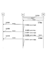
- FIG. 3 is a sequence diagram showing operations of the mobile communication system according to the first embodiment of the present invention.
- FIG. 4 is a functional block diagram of a communication application according to the first modification of the present invention.
- FIG. 5 is a sequence diagram showing an operation of the mobile communication system according to the first modification of the present invention.
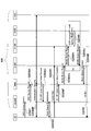
- FIG. 6 is a sequence diagram showing operations of the mobile communication system according to the first modification of the present invention.
- the mobile communication system includes a mobile station UE # 1 that starts a communication application # 1 that requires an IP routing process such as a browser, and a communication application # that requires an IP routing process such as a browser.
- 1 includes a mobile station UE # 2 connected to the externally connected device 10 activated by 1 and a network.
- the mobile communication system includes an EPC (Evolved Packet Core) network to which PMIPv6 (Proxy Mobile IP) or GTP (GPRS Tunneling Protocol) is applied as a network.
- EPC Evolved Packet Core
- PMIPv6 Proxy Mobile IP
- GTP GPRS Tunneling Protocol
- Such networks include: UTRAN (Universal Terrestrial Radio Access Network) / GERAN (GSM EDGE Radio Access Network), SGSN (Serving GPRS Support Node, E-Router Node, ESR). Mobility Management Entity, mobility management node), S-GW, PDN connected to PDN (Packet Data Network), HSS (Home Subscriber Server, subscriber management server), PCRF (Policy) And Charging Rules Function).
- the network transmits “RA” to the mobile station UE # 1 / # 2 at least in the Attach procedure or the PDN connection procedure of the mobile station UE # 1 / # 2. It is configured.
- the mobile station UE # 1 / # 2 may be configured to transmit “RA” including “default gateway information”.
- the communication application # 1 / # 2 when the communication application # 1 / # 2 receives “RA” via the mobile station UE # 1 / # 2, it sets “Router lifetime” and takes It is configured to retain the “default gateway information” included in the “RA” and delete the “default gateway information” to be retained if the “RA” is not received again until the “Router lifetime” expires. Yes.
- the mobile station UE # 2 is connected to the external connection device 10 where the communication application # 2 such as a browser is activated, and between the external connection device 10 (that is, the communication application # 2) and the network. It is configured to relay communication.
- the communication application # 2 such as a browser
- mobile stations UE # 1 / # 2 (hereinafter referred to as mobile stations UE) according to the present embodiment include an RA receiving unit 11, an RA transmitting unit 12, and a UE timer managing unit 13. ing.
- the RA receiving unit 11 is configured to receive “RA” from the network, for example, from the S-GW or P-GW to which the mobile station UE is connected.
- the RA transmission unit 12 is configured to transmit the “RA # 1” to the communication application 20 when “RA” is received by the RA reception unit 11.
- the RA transmission unit 12 sends the above-mentioned communication application 20 to the communication application 20 even when “RA” is not received again by the RA reception unit 11 before the “Router lifetime” in the communication application 20 expires.
- the “RA” is retransmitted.
- the UE timer management unit 13 is configured to manage the UE timer.
- the UE timer is set when “RA” is transmitted to the communication application 20 by the RA transmission unit 12, and is stopped when “RA” is received by the RA reception unit 11.
- the UE timer is configured to expire in a shorter period than “Router lifetime”.
- the RA transmitter 12 is configured to transmit (or retransmit) “RA” to the communication application 20 when the UE timer is stopped and when the UE timer expires.
- step S1001 the attach procedure of the mobile station UE is performed, and in step S1002, the network transmits “RA # 1” to the mobile station UE.
- the mobile station UE transmits “RA # 1” to the communication application 20 in step S1003, and sets a UE timer in step S1004.
- the communication application 20 retains “default gateway information” included in “RA # 1” and sets “Router lifetime”. Thereafter, the communication application 20 performs packet communication using the stored “default gateway information”.
- step S1005 a UE timer is set.
- the communication application 20 updates the stored “default gateway information” with the “default gateway information” included in the “RA # 1”, and sets “Router lifetime”. Thereafter, packet communication is performed using the updated “default gateway information”.
- step S1008 when receiving “RA # 2” from the network in step S1008, the mobile station UE stops the UE timer in step S1009, and transmits “RA # 2” to the communication application 20 in step S1010. At the same time, in step S1011 a UE timer is set.
- the mobile station UE does not respond to the communication application 20 before the “Router lifetime” in the communication application 20 expires only when there is a predetermined instruction from the network (for example, P-GW) in the Attach procedure.
- the “RA” previously transmitted may be retransmitted.
- the P-GW may be configured to give such a predetermined instruction to the mobile station UE by PCO (Protocol Configuration Option).
- PCO Protocol Configuration Option
- the P-GW performs this predetermined method for the mobile station UE by other methods (such as a method of transmitting a non-access stratum (NAS) via the MME by a signal at the time of Attach or PDN connection). It may be configured to give instructions.
- NAS non-access stratum
- the P-GW has given the above-mentioned predetermined instruction to the S-GW by a PMIP signal, a Diameter signal (via PCRF), or the like. May be notified.
- the S-GW may be configured to set the transmission timing of “RA” together with a predetermined instruction to the mobile station UE by the P-GW.
- the S-GW does not periodically transmit “RA” to the mobile station UE, and after the change of the S-GW to which the mobile station UE is connected or after the mobile station UE is in the “IDLE state” “RA” may be newly transmitted only when the state transitions from “ACTIVE state” to “ACTIVE state”.
- the mobile station UE when the mobile station UE is in the “IDLE state”, it is not necessary to periodically enter the “ACTIVE state” in order to receive “RA”. It is possible to suppress waste and waste of the battery of the mobile station UE and the external connection device 10-.
- the mobile communication system in the S5 / S8 network to which PMIP is applied, it is possible to avoid the problem that the communication application 20 becomes unable to transmit packets due to frequent switching of S-GW. it can.
- Modification 1 A mobile communication system according to the first modification will be described with reference to FIGS.
- the mobile communication system according to the modified example 8 will be described by focusing on differences from the mobile communication system according to the first embodiment described above.
- a communication application # 1 / # 2 (hereinafter referred to as communication application 20) activated on the mobile station UE # 1 or the external connection device 10 includes a reception unit 21, a management unit 22, and a transmission unit 23. It is equipped with.
- the receiving unit 21 is configured to receive “RA” via the mobile station UE.
- the management unit 22 is configured to manage “Router lifetime” and “default gateway information”.
- “Router lifetime” is configured to be set when “RA” is received by the receiving unit 21.
- the management unit 22 is configured to set “Router lifetime” and hold “default gateway information” included in “RA” when “RA” is received by the reception unit 21.
- management unit 22 is configured to delete the “default gateway information” to be held when the “RA” is not received again before the “Router lifetime” expires.
- the transmission unit 23 is configured to transmit an uplink packet via the mobile station UE or the external connection device 10.
- the transmission unit 23 is configured to transmit a packet communication call request signal to the mobile station UE even when there is no packet to be transmitted when the “Router lifetime” expires. Has been.
- step S2001 the attach procedure of the mobile station UE is performed.
- step S2002 the network transmits “RA # 1” to the mobile station UE, and the mobile station UE performs step S2003. Then, “RA # 1” is transmitted to the communication application 20.
- the communication application 20 retains “default gateway information” included in “RA # 1” and sets “Router lifetime”. Thereafter, the communication application 20 performs packet communication using the stored “default gateway information”.
- the communication application 20 detects the expiration of “Router lifetime” in step S2005, and in step S2006, regardless of the presence / absence of a packet to be transmitted, the communication application 20 sends a packet communication call request signal (RS). : Router Solicitation) is transmitted.
- RS packet communication call request signal
- step S2007 the mobile station UE transmits a “Service Request (service request signal)” to the network in the “IDLE state”.
- the “Downlink U-Plane destination information (S1 eNodeB F-TEID or S4-U SGSN F-TEID)” is set in the “Modify Bearer Request” received in step S2008G for the S-GW.
- “NW Initiated Service Request Procedure” is activated, and “RA # 2” is transmitted to the mobile station UE.
- step S2010 the mobile station UE transmits the received “RA # 2” to the communication application 20.
- the communication application 20 holds “default gateway information” included in “RA # 2” and sets “Router lifetime”. Thereafter, the communication application 20 performs packet communication using the stored “default gateway information”.
- the mobile communication system according to the first modification does not perform the operations of steps S2007 to S2009.
- the mobile station UE may be configured to retransmit “RA # 1” previously transmitted to the communication application 20 in response to the packet transmission request signal in step S2006.
- the communication application 20 transmits a packet communication call request signal (RS) to the mobile station UE. Since the “RA” can be acquired, a situation in which the communication application 20 becomes unable to communicate can be avoided.
- RS packet communication call request signal
- the first feature of the present embodiment is that when “RA (notification signal)” is received, “Router lifetime (predetermined timer)” is set and “default gateway information (packet transfer information) included in the“ RA ”is set. ”, And when the“ RA ”is not received again until the“ Router lifetime ”expires, the mobile station UE that can communicate with the communication application 20 configured to delete the“ default gateway information ”to be retained.
- the RA receiving unit 11 (notification signal receiving unit) configured to receive “RA” from the network and the RA receiving unit 11 have received “RA # 1 (first notification signal)”.
- the RA transmission configured to transmit “RA # 1” to the communication application 20 Unit 12 (notification signal transmission unit), and RA transmission unit 12 receives “RA # 2 (second notification signal)” by RA reception unit 11 before “Router lifetime” in communication application 20 expires.
- the gist is that “RA # 1” is retransmitted to the communication application 20 even if it is not received again.
- a UE timer management unit 13 (mobile station timer management unit) configured to manage a UE timer (mobile station timer) is provided. Is set when “RA” is transmitted to the communication application 20, is stopped when “RA” is received by the RA receiving unit 11, and is configured to expire in a shorter period than “Router lifetime”.
- the RA transmitter 12 is configured to transmit (or retransmit) “RA” to the communication application 20 when the UE timer is stopped and when the UE timer expires. Good.
- the RA transmission unit 12 performs communication before “Router lifetime” in the communication application 20 expires only when a predetermined instruction is received from a network (for example, P-GW).
- the application 20 may be configured to retransmit “RA # 1”.
- the second feature of the present embodiment is that when “RA” is received via the mobile station UE, “Router lifetime” is set, “default gateway information” included in “RA” is retained, and “Router lifetime” is stored. If the communication application 20 is configured to delete the retained “default gateway information” when the “RA” is not received again before the “expiration” expires, and the “Router lifetime” has expired, Even if there is no packet to be transmitted, the gist of the present invention is to include a transmission unit 23 configured to transmit a packet communication call request signal to the mobile station UE.
- a third feature of the present embodiment includes a network, a mobile station UE, and a communication application 20.
- the communication application 20 receives “RA” via the mobile station UE, the “router lifetime” is displayed. Set and retain the “default gateway information” included in the “RA”, and delete the “default gateway information” to be retained if the “RA” is not received again until the “Router lifetime” expires
- the communication application 20 can send a message to the mobile station UE even if there is no packet to be transmitted.
- a process for sending outgoing signal for packet communication The mobile station UE transmits a “Service Request (service request signal)” to the network in the “IDLE state”, and the network responds to the “Service Request” with respect to the mobile station UE.
- the gist is that the mobile station UE has a step of transmitting “RA” and a step of transmitting the received “RA” to the communication application 20.
- the operations of the mobile station UE and the communication application 20 described above may be implemented by hardware, may be implemented by a software module executed by a processor, or may be implemented by a combination of both. .
- the software modules include RAM (Random Access Memory), flash memory, ROM (Read Only Memory), EPROM (Erasable Programmable ROM), EEPROM (Electronically Erasable and Programmable, Removable ROM, Hard Disk, and Removable ROM).
- RAM Random Access Memory
- flash memory ROM (Read Only Memory)
- EPROM Erasable Programmable ROM
- EEPROM Electrically Erasable and Programmable, Removable ROM, Hard Disk, and Removable ROM.
- it may be provided in a storage medium of an arbitrary format such as a CD-ROM.
- the storage medium is connected to the processor so that the processor can read and write information from and to the storage medium. Further, such a storage medium may be integrated in the processor. Such a storage medium and processor may be provided in the ASIC. Such an ASIC may be provided in the mobile station UE or the like. Further, the storage medium and the processor may be provided in the mobile station UE or the like as a discrete component.
- the radio resource is wasted, the battery of the mobile station UE or the external connection device is wasted, and the mobile station UE transits between the “IDLE state” and the “ACTIVE state”. Therefore, it is possible to provide a mobile station, a communication application, and a mobile communication method that allow the communication application to receive “RA” before the “Router lifetime” expires, while avoiding the network processing necessary for this.
- UE ... mobile station 11 ... RA receiver 12 ... RA transmitter 13 ... UE timer manager 10 ... external connection terminal 20 ... communication application 21 ... receiver 22 ... manager 23 ... transmitter
Landscapes
- Engineering & Computer Science (AREA)
- Computer Networks & Wireless Communication (AREA)
- Signal Processing (AREA)
- Computer Security & Cryptography (AREA)
- Mobile Radio Communication Systems (AREA)
- Data Exchanges In Wide-Area Networks (AREA)
Abstract
無線リソースの浪費や、移動局UE又は外部接続機器のバッテリの浪費や、移動局UEが「IDLE状態」と「ACTIVE状態」との間を遷移するために必要なネットワーク処理を回避しつつ、通信アプリケーションが「Router lifetime」が満了するまでに「RA」を受信することを可能とする。本発明の移動局UEは、ネットワークから「RA」を受信するRA受信部11と、RA受信部11によって「RA#1」が受信された場合には、通信アプリケーション20に対して「RA#1」を送信するRA送信部12とを具備し、RA送信部12は、通信アプリケーション20における「Router lifetime」が満了する前に、RA受信部11によって「RA#2」が再度受信されていない場合であっても、通信アプリケーション20に対して「RA#1」を再送するように構成されている。
Description
本発明は、移動局、通信アプリケーション及び移動通信方法に関する。
非特許文献1の規定によれば、移動局UE(User Equipment)や移動局UEに接続可能なPC(Personal Computer)等の外部接続機器上で起動する通信アプリケーションは、「RA(Router Advertisement、ルータ通知信号)」を受信した場合、「Router lifetime(所定タイマ)」を設定して、かかる「RA」に含まれる「default gateway情報(パケット転送情報)」を保持するように構成されている。
また、かかる通信アプリケーションは、かかる「Router lifetime」が満了するまでに「RA」を受信した場合には、受信した「RA」に基づいて、保持するIPv6アドレスの有効性を更新し、かかる「default gateway情報」を更新するように構成されている。
一方、かかる通信アプリケーションは、IPv6アドレスが有効でないと判断した場合、すなわち、「Router lifetime」が満了するまでに「RA」を受信しなかった場合、保持する「default gateway情報」を削除するように構成されている。
言い換えると、かかる通信アプリケーションは、「RA」で通知された「Router lifetime(例えば、18時間)」が満了するまで、「default gateway情報」を保持し、「Router lifetime」が満了した後に、「default gateway情報」を削除するように構成されている。
なお、上述の「RA」は、かかる通信アプリケーションに割り当てる「IPv6 Prefix」や、かかる「IPv6 Prefix」が有効である時間を示す「Router lifetime」や、かかる通信アプリケーション用のパケット転送情報である「default gateway情報」を通知する信号である。
ここで、「Router lifetime」は、かかる通信アプリケーションによって保持されるタイマであり、デフォルト値として、「MaxRtrAdvInterval(ネットワーク側タイマ)」の3倍の時間が定義されている(例えば、非特許文献1参照)。
また、「MaxRtrAdvInterval」は、移動局UEの接続するS-GW(Serving Gateway、在圏ゲートウェイ)或いはP-GW(PDN Gateway、パケットデータネットワーク用ゲートウェイ)によって保持されるタイマ(最大RA送信間隔)であり、デフォルト値として、「21600秒(6時間)」が定義されている(例えば、非特許文献2参照)。
RFC4861 6.2.1
3GPP TS29.061
しかしながら、従来の移動通信システムでは、移動局UEは、通信アプリケーションに対して、「Router lifetime」が満了するまでに「RA」を送信する必要があるために、ネットワークとの間で通信を行う必要がない場合であっても、ネットワークから「RA」を受信するために、定期的に「IDLE(アイドル)状態」から「ACTIVE(アクティブ)状態」に遷移しなければならない。その結果、無線リソースの浪費や、移動局UE又は外部接続機器のバッテリの浪費や、移動局UEが「IDLE状態」と「ACTIVE状態」との間を遷移するために必要なネットワーク処理を引き起こしてしまうという問題点があった。
そこで、本発明は、上述の課題に鑑みてなされたものであり、無線リソースの浪費や、移動局UE又は外部接続機器のバッテリの浪費や、移動局UEが「IDLE状態」と「ACTIVE状態」との間を遷移するために必要なネットワーク処理を回避しつつ、通信アプリケーションが「Router lifetime」が満了するまでに「RA」を受信することを可能とする移動局、通信アプリケーション及び移動通信方法を提供することを目的とする。
本発明の第1の特徴は、通知信号を受信した場合、所定タイマを設定して該通知信号に含まれるパケット転送情報を保持し、該所定タイマが満了するまでに通知信号を再度受信しない場合に、保持する該パケット転送情報を削除するように構成されている通信アプリケーションと通信可能な移動局であって、ネットワークから通知信号を受信するように構成されている通知信号受信部と、前記通知信号受信部によって第1通知信号が受信された場合には、前記通信アプリケーションに対して該第1通知信号を送信するように構成されている通知信号送信部とを具備し、前記通知信号送信部は、前記通信アプリケーションにおける前記所定タイマが満了する前に、前記通知信号受信部によって第2通知信号が再度受信されていない場合であっても、該通信アプリケーションに対して前記第1通知信号を再送するように構成されていることを要旨とする。
本発明の第2の特徴は、移動局を介して通知信号を受信した場合、所定タイマを設定して該通知信号に含まれるパケット転送情報を保持し、該所定タイマが満了するまでに通知信号を再度受信しない場合に、保持する該パケット転送情報を削除するように構成されている通信アプリケーションであって、前記所定タイマが満了した場合には、送信すべきパケットが存在しない場合であっても、前記移動局に対して、パケット通信の発信要求信号を送信するように構成されている送信部を具備することを要旨とする。
本発明の第3の特徴は、ネットワークと移動局と通信アプリケーションとを具備しており、前記通信アプリケーションは、前記移動局を介して通知信号を受信した場合、所定タイマを設定して該通知信号に含まれるパケット転送情報を保持し、該所定タイマが満了するまでに通知信号を再度受信しない場合に、保持する該パケット転送情報削除するように構成されている移動通信システムにおける移動通信方法であって、前記通信アプリケーションが、前記所定タイマが満了した場合には、送信すべきパケットが存在しない場合であっても、前記移動局に対して、パケット通信の発信要求信号を送信する工程と、前記移動局が、アイドル状態において、前記ネットワークに対して、サービス要求信号を送信する工程と、前記ネットワークが、前記サービス要求信号に応じて、前記移動局に対して、通知信号を送信する工程と、前記移動局が、前記通信アプリケーションに対して、受信した通知信号を送信する工程とを有することを要旨とする。
(本発明の第1の実施形態に係る移動通信システム)
図1乃至図3を参照して、本発明の第1の実施形態に係る移動通信システムについて説明する。
図1乃至図3を参照して、本発明の第1の実施形態に係る移動通信システムについて説明する。
図1に示すように、本実施形態に係る移動通信システムは、ブラウザ等のIPルーチング処理を要する通信アプリケーション#1が起動する移動局UE#1や、ブラウザ等のIPルーチング処理を要する通信アプリケーション#1が起動する外部接続機器10に接続する移動局UE#2や、ネットワークを具備している。
例えば、本実施形態に係る移動通信システムは、ネットワークとして、PMIPv6(Proxy Mobile IP)或いはGTP(GPRS Tunneling Protocol)が適用されているEPC(Evolved Packet Core)ネットワークを具備する。
かかるネットワークは、UTRAN(Universal Terrestrial Radio Access Network)/GERAN(GSM EDGE Radio Access Network)や、SGSN(Serving GPRS Support Node、パケット交換機)や、E-UTARN(Evolved Universal Terrestrial Radio Access Network)や、MME(Mobility Management Entity、移動管理ノード)や、S-GWや、PDN(Packet Data Network)に接続されているP-GWや、HSS(Home Subscriber Server、加入者管理サーバ)や、PCRF(Policy and Charging Rules Function)等を具備している。
本実施形態に係る移動通信システムでは、ネットワークが、移動局UE#1/#2に対して、少なくとも移動局UE#1/#2のAttach手順或いはPDN接続手順において、「RA」を送信するように構成されている。
なお、本実施形態に係る移動通信システムでは、例えば、3GPPのTS23.402に規定するように、移動局UE#1/#2の接続するS-GWが、「MaxRtrAdvInterval」が満了した場合に、移動局UE#1/#2に対して、「default gateway情報」を含む「RA」を送信するように構成されていてもよい。
或いは、例えば、3GPPのTS23.401に規定するように、移動局UE#1/#2の接続するP-GWが、「MaxRtrAdvInterval」が満了した場合に、移動局UE#1/#2に対して、「default gateway情報」を含む「RA」を送信するように構成されていてもよい。
また、本実施形態に係る移動通信システムでは、通信アプリケーション#1/#2は、移動局UE#1/#2を介して「RA」を受信した場合、「Router lifetime」を設定して、かかる「RA」に含まれる「default gateway情報」を保持し、かかる「Router lifetime」が満了するまでに「RA」を再度受信しない場合に、保持する「default gateway情報」を削除するように構成されている。
本実施形態に係る移動局UE#2は、ブラウザ等の通信アプリケーション#2が起動する外部接続機器10に接続されて、かかる外部接続機器10(すなわち、通信アプリケーション#2)とネットワークとの間の通信を中継するように構成されている。
図2に示すように、本実施形態に係る移動局UE#1/#2(以下、移動局UE)は、RA受信部11と、RA送信部12と、UEタイマ管理部13とを具備している。
RA受信部11は、ネットワークから、例えば、移動局UEの接続するS-GW或いはP-GWから、「RA」を受信するように構成されている。
RA送信部12は、RA受信部11によって「RA」が受信された場合には、通信アプリケーション20に対して、かかる「RA#1」を送信するように構成されている。
なお、RA送信部12は、通信アプリケーション20における「Router lifetime」が満了する前に、RA受信部11によって「RA」が再度受信されていない場合であっても、通信アプリケーション20に対して、上述の「RA」を再送するように構成されている。
UEタイマ管理部13は、UEタイマを管理するように構成されている。
ここで、UEタイマは、RA送信部12によって通信アプリケーション20に対して「RA」が送信された場合に設定され、RA受信部11によって「RA」が受信された場合に停止される。
また、UEタイマは、「Router lifetime」よりも短い期間で満了するように構成されている。
なお、RA送信部12は、UEタイマが停止された場合及びUEタイマが満了した場合に、通信アプリケーション20に対して、「RA」を送信(又は、再送)するように構成されている。
以下、図3を参照して、本実施形態に係る移動通信システムの動作について説明する。
図3に示すように、ステップS1001において、移動局UEのAttach手順が行われ、ステップS1002において、ネットワークは、移動局UEに対して「RA#1」を送信する。
移動局UEは、ステップS1003において、通信アプリケーション20に対して「RA#1」を送信すると共に、ステップS1004において、UEタイマを設定する。
ここで、通信アプリケーション20は、「RA#1」に含まれる「default gateway情報」を保持し、「Router lifetime」を設定する。以降、通信アプリケーション20は、保持した「default gateway情報」を用いてパケット通信を行う。
その後、移動局UEは、ステップS1005において、ネットワークから、新たな「RA」を受信することなく、UEタイマの満了を検知すると、ステップS1006において、通信アプリケーション20に対して「RA#1」を再送すると共に、ステップS1007において、UEタイマを設定する。
ここで、通信アプリケーション20は、「RA#1」に含まれる「default gateway情報」によって、保持する「default gateway情報」を更新し、「Router lifetime」を設定する。以降、更新した「default gateway情報」を用いてパケット通信を行う。
その後、移動局UEは、ステップS1008において、ネットワークから「RA#2」を受信すると、ステップS1009において、UEタイマを停止し、ステップS1010において、通信アプリケーション20に対して「RA#2」を送信すると共に、ステップS1011において、UEタイマを設定する。
なお、移動局UEは、Attach手順において、ネットワーク(例えば、P-GW等)から所定の指示があった場合にのみ、通信アプリケーション20における「Router lifetime」が満了する前に、通信アプリケーション20に対して以前に送信した「RA」を再送するように構成されていてもよい。
かかる場合、P-GWは、PCO(Protocol Configuration Option)により、移動局UEに対して、かかる所定の指示を行うように構成されていてもよい。
或いは、P-GWは、その他の方法(Attach或いはPDN接続時の信号等により、MMEを介してNAS(Non-Access Stratum)信号を送信する方法等)によって、移動局UEに対して、かかる所定の指示を行うように構成されていてもよい。
なお、かかる方法は、GTPを適用するS5/S8ネットワークにおいても有効である。
また、PMIPを適用するS5/S8では、かかる方法に加えて、P-GWが、PMIP信号やDiameter信号(PCRF経由)等により、S-GWに対して、上述の所定の指示を行ったことを通知してもよい。
かかる場合、S-GWは、P-GWによる移動局UEへの所定の指示に併せて、「RA」の送信タイミングを設定するように構成されていてもよい。
例えば、S-GWは、移動局UEに対して、「RA」を定期的に送信せず、移動局UEの接続するS-GWの変更が発生した後や、移動局UEが「IDLE状態」から「ACTIVE状態」に遷移した場合等のみに、「RA」を新たに送信するように構成されていてもよい。
本実施形態に係る移動通信システムによれば、移動局UEが「IDLE状態」である場合において「RA」を受信するために、定期的に「ACTIVE状態」になる必要がないため、無線リソースの浪費や、移動局UEや外部接続機器10-のバッテリの浪費を抑えることができる。
また、本実施形態に係る移動通信システムによれば、PMIPを適用するS5/S8ネットワークにおいて、S-GWの頻繁な切り替えに伴い、通信アプリケーション20がパケットを送信できなくなるという不具合を回避することができる。
(変更例1)
図4乃至6を参照して、本変更例1に係る移動通信システムについて説明する。以下、本変更例8に係る移動通信システムについて、上述の第1の実施形態に係る移動通信システムとの相違点に着目して説明する。
図4乃至6を参照して、本変更例1に係る移動通信システムについて説明する。以下、本変更例8に係る移動通信システムについて、上述の第1の実施形態に係る移動通信システムとの相違点に着目して説明する。
図4に示すように、移動局UE#1又は外部接続機器10上で起動する通信アプリケーション#1/#2(以下、通信アプリケーション20)は、受信部21と、管理部22と、送信部23とを具備している。
受信部21は、移動局UEを介して「RA」を受信するように構成されている。
管理部22は、「Router lifetime」や「default gateway情報」を管理するように構成されている。
ここで、「Router lifetime」は、受信部21によって「RA」が受信された場合に設定されるように構成されている。
なお、管理部22は、受信部21によって「RA」が受信された場合に、「Router lifetime」を設定して「RA」に含まれる「default gateway情報」を保持するように構成されている。
また、管理部22は、「Router lifetime」が満了するまでに「RA」を再度受信しない場合に、保持する「default gateway情報」を削除するように構成されている。
送信部23は、移動局UEや外部接続機器10を介して、上りパケットを送信するように構成されている。
なお、送信部23は、「Router lifetime」が満了した場合には、送信すべきパケットが存在しない場合であっても、移動局UEに対して、パケット通信の発信要求信号を送信するように構成されている。
以下、図5及び図6を参照して、本変更例1に係る移動通信システムの動作について説明する。
図5に示すように、ステップS2001において、移動局UEのAttach手順が行われ、ステップS2002において、ネットワークは、移動局UEに対して「RA#1」を送信し、移動局UEは、ステップS2003において、通信アプリケーション20に対して「RA#1」を送信する。
ここで、通信アプリケーション20は、「RA#1」に含まれる「default gateway情報」を保持し、「Router lifetime」を設定する。以降、通信アプリケーション20は、保持した「default gateway情報」を用いてパケット通信を行う。
その後、通信アプリケーション20は、ステップS2005において、「Router lifetime」の満了を検知し、ステップS2006において、送信すべきパケットの有無に関わらず、移動局UEに対して、パケット通信の発信要求信号(RS:Router Solicitation)を送信する。
ステップS2007において、移動局UEは、「IDLE状態」において、ネットワークに対して、「Service Request(サービス要求信号)」を送信する。
ネットワークは、かかる「Service Request」を受信すると、例えば、図4に示す手順、すなわち、3GPPのTS23.401のFigure5.3.4.1-1に規定されている「UE triggered Service Request Procedure」を行う。
ここで、S-GWは、ステップS2008Gにおいて受信した「Modify Bearer Request」に「下りU-Plane宛先情報(S1 eNodeB F-TEID、又は、S4-U SGSN F-TEID)」が設定されていることを確認し、U-Planeの確立後に、すなわち、ステップS2009において、「NW Initiated Service Request Procedure」を起動し、移動局UEに対して、「RA#2」を送信する。
ステップS2010において、移動局UEは、通信アプリケーション20に対して、受信した「RA#2」を送信する。
ここで、通信アプリケーション20は、「RA#2」に含まれる「default gateway情報」を保持し、「Router lifetime」を設定する。以降、通信アプリケーション20は、保持した「default gateway情報」を用いてパケット通信を行う。
なお、移動局UEが、ネットワーク(例えば、P-GW)によって、上述の所定の指示が行われている場合、本変更例1に係る移動通信システムにおいて、ステップS2007乃至S2009の動作を行うことなく、移動局UEは、ステップS2006のパケット発信要求信号に応じて、通信アプリケーション20に対して、以前に送信した「RA#1」を再送するように構成されていてもよい。
本変更例1に係る移動通信システムによれば、「Router lifetime」が満了した場合には、通信アプリケーション20が、移動局UEに対してパケット通信の発信要求信号(RS)を送信することによって「RA」を取得することができるように構成されているため、通信アプリケーション20が通信できなくなるという事態を回避することができる。
以上に述べた本実施形態の特徴は、以下のように表現されていてもよい。
本実施形態の第1の特徴は、「RA(通知信号)」を受信した場合、「Router lifetime(所定タイマ)」を設定して該「RA」に含まれる「default gateway情報(パケット転送情報)」を保持し、「Router lifetime」が満了するまでに「RA」を再度受信しない場合に、保持する「default gateway情報」を削除するように構成されている通信アプリケーション20と通信可能な移動局UEであって、ネットワークから「RA」を受信するように構成されているRA受信部11(通知信号受信部)と、RA受信部11によって「RA#1(第1通知信号)」が受信された場合には、通信アプリケーション20に対して「RA#1」を送信するように構成されているRA送信部12(通知信号送信部)とを具備し、RA送信部12は、通信アプリケーション20における「Router lifetime」が満了する前に、RA受信部11によって「RA#2(第2通知信号)」が再度受信されていない場合であっても、通信アプリケーション20に対して「RA#1」を再送するように構成されていることを要旨とする。
本実施形態の第1の特徴において、UEタイマ(移動局タイマ)を管理するように構成されているUEタイマ管理部13(移動局タイマ管理部)を具備し、UEタイマは、RA送信部12によって通信アプリケーション20に対して「RA」が送信された場合に設定され、RA受信部11によって「RA」が受信された場合に停止され、「Router lifetime」よりも短い期間で満了するように構成されており、RA送信部12は、UEタイマが停止された場合及びUEタイマが満了した場合に、通信アプリケーション20に対して「RA」を送信(又は、再送)するように構成されていてもよい。
本実施形態の第1の特徴において、RA送信部12は、ネットワーク(例えば、P-GW)から所定の指示があった場合にのみ、通信アプリケーション20における「Router lifetime」が満了する前に、通信アプリケーション20に対して「RA#1」を再送するように構成されていてもよい。
本実施形態の第2の特徴は、移動局UEを介して「RA」を受信した場合、「Router lifetime」を設定して「RA」に含まれる「default gateway情報」を保持し、「Router lifetime」が満了するまでに「RA」を再度受信しない場合に、保持する「default gateway情報」を削除するように構成されている通信アプリケーション20であって、「Router lifetime」が満了した場合には、送信すべきパケットが存在しない場合であっても、移動局UEに対して、パケット通信の発信要求信号を送信するように構成されている送信部23を具備することを要旨とする。
本実施形態の第3の特徴は、ネットワークと移動局UEと通信アプリケーション20とを具備しており、通信アプリケーション20は、移動局UEを介して「RA」を受信した場合、「Router lifetime」を設定して「RA」に含まれる「default gateway情報」を保持し、「Router lifetime」が満了するまでに「RA」を再度受信しない場合に、保持する「default gateway情報」を削除するように構成されている移動通信システムにおける移動通信方法であって、通信アプリケーション20が、「Router lifetime」が満了した場合には、送信すべきパケットが存在しない場合であっても、移動局UEに対して、パケット通信の発信要求信号を送信する工程と、移動局UEが、「IDLE状態」において、ネットワークに対して、「Service Request(サービス要求信号)」を送信する工程と、ネットワークが、「Service Request」に応じて、移動局UEに対して「RA」を送信する工程と、移動局UEが、通信アプリケーション20に対して、受信した「RA」を送信する工程とを有することを要旨とする。
なお、上述の移動局UEや通信アプリケーション20等の動作は、ハードウェアによって実施されてもよいし、プロセッサによって実行されるソフトウェアモジュールによって実施されてもよいし、両者の組み合わせによって実施されてもよい。
ソフトウェアモジュールは、RAM(Random Access Memory)や、フラッシュメモリや、ROM(Read Only Memory)や、EPROM(Erasable Programmable ROM)や、EEPROM(Electronically Erasable and Programmable ROM)や、レジスタや、ハードディスクや、リムーバブルディスクや、CD-ROMといった任意形式の記憶媒体内に設けられていてもよい。
かかる記憶媒体は、プロセッサが当該記憶媒体に情報を読み書きできるように、当該プロセッサに接続されている。また、かかる記憶媒体は、プロセッサに集積されていてもよい。また、かかる記憶媒体及びプロセッサは、ASIC内に設けられていてもよい。かかるASICは、移動局UE等内に設けられていてもよい。また、かかる記憶媒体及びプロセッサは、ディスクリートコンポーネントとして移動局UE等内に設けられていてもよい。
以上、上述の実施形態を用いて本発明について詳細に説明したが、当業者にとっては、本発明が本明細書中に説明した実施形態に限定されるものではないということは明らかである。本発明は、請求の範囲の記載により定まる本発明の趣旨及び範囲を逸脱することなく修正及び変更態様として実施することができる。従って、本明細書の記載は、例示説明を目的とするものであり、本発明に対して何ら制限的な意味を有するものではない。
なお、日本国特許出願第2011-026584号(2011年2月9日出願)の全内容が、参照により、本願明細書に組み込まれている。
以上説明したように、本発明によれば、無線リソースの浪費や、移動局UE又は外部接続機器のバッテリの浪費や、移動局UEが「IDLE状態」と「ACTIVE状態」との間を遷移するために必要なネットワーク処理を回避しつつ、通信アプリケーションが「Router lifetime」が満了するまでに「RA」を受信することを可能とする移動局、通信アプリケーション及び移動通信方法を提供することができる。
UE…移動局
11…RA受信部
12…RA送信部
13…UEタイマ管理部
10…外部接続端末
20…通信アプリケーション
21…受信部
22…管理部
23…送信部
11…RA受信部
12…RA送信部
13…UEタイマ管理部
10…外部接続端末
20…通信アプリケーション
21…受信部
22…管理部
23…送信部
Claims (5)
- 通知信号を受信した場合、所定タイマを設定して該通知信号に含まれるパケット転送情報を保持し、該所定タイマが満了するまでに通知信号を再度受信しない場合に、保持する該パケット転送情報を削除するように構成されている通信アプリケーションと通信可能な移動局であって、
ネットワークから通知信号を受信するように構成されている通知信号受信部と、
前記通知信号受信部によって第1通知信号が受信された場合には、前記通信アプリケーションに対して該第1通知信号を送信するように構成されている通知信号送信部とを具備し、
前記通知信号送信部は、前記通信アプリケーションにおける前記所定タイマが満了する前に、前記通知信号受信部によって第2通知信号が再度受信されていない場合であっても、該通信アプリケーションに対して前記第1通知信号を再送するように構成されていることを特徴とする移動局。 - 移動局タイマを管理するように構成されている移動局タイマ管理部を具備し、
前記移動局タイマは、前記通知信号送信部によって前記通信アプリケーションに対して通知信号が送信された場合に設定され、前記通知信号受信部によって通知信号が受信された場合に停止され、前記所定タイマよりも短い期間で満了するように構成されており、
前記通知信号送信部は、前記移動局タイマが停止された場合及び該移動局タイマが満了した場合に、前記通信アプリケーションに対して通知信号を送信するように構成されていることを特徴とする請求項1に記載の移動局。 - 前記通知信号送信部は、前記ネットワークから所定の指示があった場合にのみ、前記通信アプリケーションにおける前記所定タイマが満了する前に、該通信アプリケーションに対して前記第1通知信号を再送するように構成されていることを特徴とする請求項1又は2に記載の移動局。
- 移動局を介して通知信号を受信した場合、所定タイマを設定して該通知信号に含まれるパケット転送情報を保持し、該所定タイマが満了するまでに通知信号を再度受信しない場合に、保持する該パケット転送情報を削除するように構成されている通信アプリケーションであって、
前記所定タイマが満了した場合には、送信すべきパケットが存在しない場合であっても、前記移動局に対して、パケット通信の発信要求信号を送信するように構成されている送信部を具備することを特徴とする通信アプリケーション。 - ネットワークと移動局と通信アプリケーションとを具備しており、
前記通信アプリケーションは、前記移動局を介して通知信号を受信した場合、所定タイマを設定して該通知信号に含まれるパケット転送情報を保持し、該所定タイマが満了するまでに通知信号を再度受信しない場合に、保持する該パケット転送情報削除するように構成されている移動通信システムにおける移動通信方法であって、
前記通信アプリケーションが、前記所定タイマが満了した場合には、送信すべきパケットが存在しない場合であっても、前記移動局に対して、パケット通信の発信要求信号を送信する工程Aと、
前記移動局が、アイドル状態において、前記ネットワークに対して、サービス要求信号を送信する工程Bと、
前記ネットワークが、前記サービス要求信号に応じて、前記移動局に対して、通知信号を送信する工程Cと、
前記移動局が、前記通信アプリケーションに対して、受信した通知信号を送信する工程Dとを有することを特徴とする移動通信方法。
Priority Applications (1)
| Application Number | Priority Date | Filing Date | Title |
|---|---|---|---|
| US13/983,087 US20130308546A1 (en) | 2011-02-09 | 2012-02-08 | Mobile station, communication application, and mobile communication method |
Applications Claiming Priority (2)
| Application Number | Priority Date | Filing Date | Title |
|---|---|---|---|
| JP2011026584A JP5438043B2 (ja) | 2011-02-09 | 2011-02-09 | 移動局、通信アプリケーション及び移動通信方法 |
| JP2011-026584 | 2011-02-09 |
Publications (1)
| Publication Number | Publication Date |
|---|---|
| WO2012108468A1 true WO2012108468A1 (ja) | 2012-08-16 |
Family
ID=46638681
Family Applications (1)
| Application Number | Title | Priority Date | Filing Date |
|---|---|---|---|
| PCT/JP2012/052867 Ceased WO2012108468A1 (ja) | 2011-02-09 | 2012-02-08 | 移動局、通信アプリケーション及び移動通信方法 |
Country Status (3)
| Country | Link |
|---|---|
| US (1) | US20130308546A1 (ja) |
| JP (1) | JP5438043B2 (ja) |
| WO (1) | WO2012108468A1 (ja) |
Families Citing this family (3)
| Publication number | Priority date | Publication date | Assignee | Title |
|---|---|---|---|---|
| US9998360B2 (en) * | 2014-11-17 | 2018-06-12 | Honeywell International Inc. | Minimizining message propagation times when brief datalink interruptions occur |
| FR3041846A1 (fr) * | 2015-09-29 | 2017-03-31 | Orange | Technique de gestion d'une adresse dans un reseau local |
| JP7258586B2 (ja) * | 2019-02-15 | 2023-04-17 | 株式会社Nttドコモ | 移動機、中継ノード及び通信制御方法 |
Citations (2)
| Publication number | Priority date | Publication date | Assignee | Title |
|---|---|---|---|---|
| JP2008035248A (ja) * | 2006-07-28 | 2008-02-14 | Fujitsu Ltd | 中継装置 |
| WO2010029798A1 (ja) * | 2008-09-10 | 2010-03-18 | 日本電気株式会社 | 通信システム、ネットワークノード、移動ノード、通信方法、およびプログラム |
Family Cites Families (12)
| Publication number | Priority date | Publication date | Assignee | Title |
|---|---|---|---|---|
| KR100592451B1 (ko) * | 1997-01-06 | 2006-06-22 | 텔레호낙티에볼라게트 엘엠 에릭슨(피유비엘) | 지능형 단말 애플리케이션 프로토콜 |
| JP4020576B2 (ja) * | 2000-09-14 | 2007-12-12 | 株式会社東芝 | パケット転送方法、移動端末装置及びルータ装置 |
| JP4136694B2 (ja) * | 2003-02-07 | 2008-08-20 | キヤノン株式会社 | 無線端末、基地局および通信リンク維持方法 |
| JP2006086718A (ja) * | 2004-09-15 | 2006-03-30 | Fujitsu Ltd | アクセスルータ及び端末装置 |
| US7809357B2 (en) * | 2005-05-20 | 2010-10-05 | Microsoft Corporation | System and method for optimizing network communication in response to network conditions |
| JP4996077B2 (ja) * | 2005-08-01 | 2012-08-08 | 古野電気株式会社 | ネットワークシステム、通信中継装置、通信端末装置、および通信端末装置用プログラム |
| US7873003B2 (en) * | 2006-11-08 | 2011-01-18 | Electronics And Telecommunications Research Institute | Method for allocating IP address to mobile station in mobile communication system |
| US8942212B2 (en) * | 2007-02-19 | 2015-01-27 | Nec Corporation | Autoconfiguration system for wireless sensor network and its method, and gateway apparatus for wireless sensor network |
| US7706304B2 (en) * | 2007-06-21 | 2010-04-27 | Telefonaktiebolaget L M Ericsson (Publ) | Method and system for assigning routers to hosts |
| KR101719983B1 (ko) * | 2009-07-27 | 2017-04-10 | 엘지전자 주식회사 | 이동통신 단말에 ip 주소를 할당하는 방법 |
| JP4883539B2 (ja) * | 2009-10-07 | 2012-02-22 | 株式会社エヌ・ティ・ティ・ドコモ | 移動通信方法、移動管理用ノード、測位演算用ノード及び移動局 |
| US9301333B2 (en) * | 2010-09-28 | 2016-03-29 | Blackberry Limited | Method and apparatus for releasing connection with local GW when UE moves out of the residential/enterprise network coverage |
-
2011
- 2011-02-09 JP JP2011026584A patent/JP5438043B2/ja not_active Expired - Fee Related
-
2012
- 2012-02-08 US US13/983,087 patent/US20130308546A1/en not_active Abandoned
- 2012-02-08 WO PCT/JP2012/052867 patent/WO2012108468A1/ja not_active Ceased
Patent Citations (2)
| Publication number | Priority date | Publication date | Assignee | Title |
|---|---|---|---|---|
| JP2008035248A (ja) * | 2006-07-28 | 2008-02-14 | Fujitsu Ltd | 中継装置 |
| WO2010029798A1 (ja) * | 2008-09-10 | 2010-03-18 | 日本電気株式会社 | 通信システム、ネットワークノード、移動ノード、通信方法、およびプログラム |
Also Published As
| Publication number | Publication date |
|---|---|
| US20130308546A1 (en) | 2013-11-21 |
| JP2012169711A (ja) | 2012-09-06 |
| JP5438043B2 (ja) | 2014-03-12 |
Similar Documents
| Publication | Publication Date | Title |
|---|---|---|
| US10674546B2 (en) | Method for establishing transmission channel, MME, network element device, system and storage medium | |
| US9392634B2 (en) | Node and method for connection re-establishment | |
| US9723511B2 (en) | Node and method for buffering downlink data | |
| KR101922856B1 (ko) | 모바일 네트워크를 통한 사용자 평면 트랜잭션의 지원 | |
| EP2583508B1 (en) | P-gw/ggsn issued paging requests | |
| JP6278959B2 (ja) | Pdn接続の撤回可能な削除のための方法 | |
| US20130142120A1 (en) | Mobile communication method and call session control server device | |
| US20130343325A1 (en) | Mobile communication method | |
| US8885608B2 (en) | Mobile communication method | |
| US9320078B2 (en) | Mobile communication method, mobile management node, and serving gateway apparatus | |
| CN105325041A (zh) | 一种用户设备节约电量的方法和设备 | |
| WO2017028637A1 (zh) | 网关的恢复处理方法及装置 | |
| JP5438043B2 (ja) | 移動局、通信アプリケーション及び移動通信方法 | |
| JP5450474B2 (ja) | 移動通信システム、移動通信方法、パケットデータネットワーク用ゲートウェイ及び在圏ゲートウェイ | |
| CN107005838B (zh) | 数据传输的方法和设备 | |
| JP5061160B2 (ja) | 移動通信方法、移動通信システム及びインターワーキング装置 | |
| JP5774926B2 (ja) | 移動通信方法 | |
| KR20090045778A (ko) | 상향 베어러와 하향 베어러를 비동기적으로 생성하는이동통신 망에서 이동성 관리부의 부하를 줄이는 데이터송신 방법 및 시스템 | |
| JP5508522B2 (ja) | 一時的バインディング・オプション・メッセージングを使用したセッションの中断および再開 | |
| WO2021163855A1 (zh) | 信息发送方法、接收方法、装置、设备及存储介质 | |
| WO2012174962A1 (zh) | 用户本地访问业务的处理方法、装置和系统 |
Legal Events
| Date | Code | Title | Description |
|---|---|---|---|
| 121 | Ep: the epo has been informed by wipo that ep was designated in this application |
Ref document number: 12744359 Country of ref document: EP Kind code of ref document: A1 |
|
| WWE | Wipo information: entry into national phase |
Ref document number: 13983087 Country of ref document: US |
|
| NENP | Non-entry into the national phase |
Ref country code: DE |
|
| 122 | Ep: pct application non-entry in european phase |
Ref document number: 12744359 Country of ref document: EP Kind code of ref document: A1 |