WO2012108416A1 - アルカリ形燃料電池システム - Google Patents
アルカリ形燃料電池システム Download PDFInfo
- Publication number
- WO2012108416A1 WO2012108416A1 PCT/JP2012/052710 JP2012052710W WO2012108416A1 WO 2012108416 A1 WO2012108416 A1 WO 2012108416A1 JP 2012052710 W JP2012052710 W JP 2012052710W WO 2012108416 A1 WO2012108416 A1 WO 2012108416A1
- Authority
- WO
- WIPO (PCT)
- Prior art keywords
- humidity
- fuel cell
- unit
- reducing agent
- alkaline fuel
- Prior art date
- Legal status (The legal status is an assumption and is not a legal conclusion. Google has not performed a legal analysis and makes no representation as to the accuracy of the status listed.)
- Ceased
Links
Images










Classifications
-
- H—ELECTRICITY
- H01—ELECTRIC ELEMENTS
- H01M—PROCESSES OR MEANS, e.g. BATTERIES, FOR THE DIRECT CONVERSION OF CHEMICAL ENERGY INTO ELECTRICAL ENERGY
- H01M8/00—Fuel cells; Manufacture thereof
- H01M8/08—Fuel cells with aqueous electrolytes
- H01M8/083—Alkaline fuel cells
-
- H—ELECTRICITY
- H01—ELECTRIC ELEMENTS
- H01M—PROCESSES OR MEANS, e.g. BATTERIES, FOR THE DIRECT CONVERSION OF CHEMICAL ENERGY INTO ELECTRICAL ENERGY
- H01M8/00—Fuel cells; Manufacture thereof
- H01M8/04—Auxiliary arrangements, e.g. for control of pressure or for circulation of fluids
- H01M8/04298—Processes for controlling fuel cells or fuel cell systems
- H01M8/04313—Processes for controlling fuel cells or fuel cell systems characterised by the detection or assessment of variables; characterised by the detection or assessment of failure or abnormal function
- H01M8/04537—Electric variables
- H01M8/04574—Current
- H01M8/04589—Current of fuel cell stacks
-
- H—ELECTRICITY
- H01—ELECTRIC ELEMENTS
- H01M—PROCESSES OR MEANS, e.g. BATTERIES, FOR THE DIRECT CONVERSION OF CHEMICAL ENERGY INTO ELECTRICAL ENERGY
- H01M8/00—Fuel cells; Manufacture thereof
- H01M8/04—Auxiliary arrangements, e.g. for control of pressure or for circulation of fluids
- H01M8/04298—Processes for controlling fuel cells or fuel cell systems
- H01M8/04694—Processes for controlling fuel cells or fuel cell systems characterised by variables to be controlled
- H01M8/04746—Pressure; Flow
- H01M8/04753—Pressure; Flow of fuel cell reactants
-
- H—ELECTRICITY
- H01—ELECTRIC ELEMENTS
- H01M—PROCESSES OR MEANS, e.g. BATTERIES, FOR THE DIRECT CONVERSION OF CHEMICAL ENERGY INTO ELECTRICAL ENERGY
- H01M8/00—Fuel cells; Manufacture thereof
- H01M8/04—Auxiliary arrangements, e.g. for control of pressure or for circulation of fluids
- H01M8/04298—Processes for controlling fuel cells or fuel cell systems
- H01M8/04694—Processes for controlling fuel cells or fuel cell systems characterised by variables to be controlled
- H01M8/04828—Humidity; Water content
- H01M8/04835—Humidity; Water content of fuel cell reactants
-
- Y—GENERAL TAGGING OF NEW TECHNOLOGICAL DEVELOPMENTS; GENERAL TAGGING OF CROSS-SECTIONAL TECHNOLOGIES SPANNING OVER SEVERAL SECTIONS OF THE IPC; TECHNICAL SUBJECTS COVERED BY FORMER USPC CROSS-REFERENCE ART COLLECTIONS [XRACs] AND DIGESTS
- Y02—TECHNOLOGIES OR APPLICATIONS FOR MITIGATION OR ADAPTATION AGAINST CLIMATE CHANGE
- Y02E—REDUCTION OF GREENHOUSE GAS [GHG] EMISSIONS, RELATED TO ENERGY GENERATION, TRANSMISSION OR DISTRIBUTION
- Y02E60/00—Enabling technologies; Technologies with a potential or indirect contribution to GHG emissions mitigation
- Y02E60/30—Hydrogen technology
- Y02E60/50—Fuel cells
Definitions
- the present invention relates to an alkaline fuel cell system capable of optimally adjusting the humidity (water content) of an electrode (anode electrode and / or cathode electrode) of an alkaline fuel cell.
- the fuel cell includes a membrane electrode assembly (MEA) having a configuration in which an electrolyte membrane is sandwiched between an anode and a cathode as a main part of power generation.
- MEA membrane electrode assembly
- a polymer electrolyte fuel cell (direct fuel) Battery) phosphoric acid fuel cell, molten carbonate fuel cell, solid oxide fuel cell, alkaline fuel cell and the like.
- An alkaline fuel cell is a fuel cell in which an anion exchange membrane is used as an electrolyte membrane, and charge carriers are hydroxide ions (OH ⁇ ) [see, for example, JP-A-11-135137 (Patent Document 1)]. .
- charge carriers are hydroxide ions (OH ⁇ ) [see, for example, JP-A-11-135137 (Patent Document 1)].
- electric power is taken out by the following electrochemical reaction.
- the supplied reducing agent (fuel), for example, H 2 gas and OH ⁇ transmitted from the cathode electrode are expressed by the following formula (2):
- the anion conduction resistance of the electrolyte membrane increases due to the electrolyte membrane being in a dry state (hereinafter also referred to as “dry-up”). Both “flooding” and “dry up” cause the output voltage of the alkaline fuel cell to decrease.
- An object of the present invention is to provide an alkali that can stably maintain a high output voltage by optimally adjusting the humidity (water content) of an electrode (anode electrode and / or cathode electrode) of an alkaline fuel cell. To provide a fuel cell system.
- the above equation (3) means that the humidity of the anode electrode can be controlled by adjusting the flow rate N t of the reducing agent and / or the humidity ⁇ w of the reducing agent introduced into the anode electrode.
- the humidity of the anode electrode (the reducing agent humidity in the anode electrode) can be determined from the humidity of the reducing agent discharged from the anode electrode.
- the flow rate of the oxidant supplied to the cathode electrode of the alkaline fuel cell (flow rate immediately before being introduced into the cathode electrode) is N t ′, and the humidity of the oxidant is ⁇ w ′ (where 0 ⁇ ⁇ w ′). If ⁇ 1), the water content of this oxidant is ⁇ w ′ ⁇ N t ′. If the amount of water consumed in the cathode electrode is N r ′, the flow rate of the oxidizing agent in the cathode electrode is approximately N t ′, and the water content is ⁇ w ′ ⁇ N t ′ ⁇ N Calculated as r '.
- the above equation (4) means that the humidity of the cathode electrode can be controlled by adjusting the flow rate N t ′ of the oxidant and / or the humidity ⁇ w ′ of the oxidant introduced into the cathode electrode.
- the humidity of the cathode electrode (humidity of the oxidant in the cathode electrode) can be grasped from the humidity of the oxidant discharged from the cathode electrode. It can also be seen that when the amount of current flowing between the anode and cathode increases and the amount of water N r ′ consumed in the cathode increases, the humidity of the cathode decreases.
- the present invention has been made through various studies based on the above-described idea by the present inventors.
- the present invention provides the following alkaline fuel cell systems [A] to [D].
- a fuel cell unit a reducing agent supply unit for supplying a reducing agent to the anode electrode, an oxidizing agent supply unit for supplying an oxidizing agent to the cathode electrode, and a flow rate of the reducing agent supplied to the anode electrode and / or
- at least a first adjustment unit for adjusting humidity and a change amount ⁇ i (hereinafter also simply referred to as ⁇ i) per unit time of a current value flowing between the anode and the cathode of the alkaline fuel cell are detected.
- the first adjustment unit is connected to the first adjustment unit and the first detection unit, and the flow rate and / or humidity of the reducing agent is adjusted by the first adjustment unit based on the detection result by the first detection unit.
- An alkaline fuel cell system comprising a first control unit for controlling the fuel cell.
- the first detection unit calculates a change amount ⁇ V (hereinafter also simply referred to as ⁇ V) of the output voltage value of the alkaline fuel cell and a change rate ⁇ R (hereinafter simply referred to as ⁇ R) of the resistance value per unit time. Furthermore, it is preferable to detect.
- ⁇ V change amount
- ⁇ R change rate
- the alkaline fuel cell system [A] adjusts the humidity of the anode electrode by, for example, the following control.
- the first control unit causes the first adjustment unit to Control is performed to reduce the flow rate and / or increase the humidity of the reducing agent, and when ⁇ i detected by the first detector is larger than a predetermined value B i (where B i is a positive value).
- the first control unit controls the first adjustment unit to increase the flow rate of the reducing agent and / or reduce the humidity of the reducing agent.
- the predetermined value A i of ⁇ i is preferably in the range of ⁇ 50 to ⁇ 25 [mA / cm 2 ⁇ min], and the predetermined value B i is preferably in the range of +25 to +50 [mA / cm 2 ⁇ min]. Is within.
- ⁇ R detected by the first detection unit is greater than the predetermined value C R is the first control unit, the first adjustment portion performs an increase in the humidity of the reduction and / or a reducing agent in the flow rate of the reducing agent To control.
- ⁇ R is the predetermined value C R, preferably in the range of + 5 to + 20 [% / min], a predetermined value D V of ⁇ V is preferably in the range of -50 to -2 [mV / min].
- the first control unit controls the first detection unit to detect ⁇ R, and ⁇ R is a predetermined value C R (where C R is a positive value).
- the first adjusting unit controls to increase the flow rate of the reducing agent and / or reduce the humidity of the reducing agent.
- the first adjustment portion performs an increase in the humidity of the reduction and / or a reducing agent in the flow rate of the reducing agent To control.
- Predetermined value D V of ⁇ V is preferably in the range of -50 to -2 [mV / min]
- a predetermined value C R of ⁇ R are in the range of preferably from + 5 to + 20 [% / min].
- the alkaline fuel cell included in the alkaline fuel cell system of [A] can include an anode separator, an anode electrode, an anion conductive electrolyte membrane, a cathode electrode, and a cathode separator in this order.
- the fuel cell unit can include two or more alkaline fuel cells that are electrically connected in series or in parallel.
- the reducing agent supply unit may include, for example, a pipe that connects a reducing agent supply source that holds the reducing agent and an anode separator of the alkaline fuel cell.
- the first adjustment unit can be a flow rate adjustment valve and / or a humidity controller provided in the pipe.
- An alkaline fuel cell system capable of optimally adjusting the humidity of the cathode electrode of an alkaline fuel cell, comprising an anode fuel cell, an anion conductive electrolyte membrane, and a cathode electrode in this order.
- a fuel cell unit Including a fuel cell unit, a reducing agent supplying unit for supplying a reducing agent to the anode electrode, an oxidizing agent supplying unit for supplying an oxidizing agent to the cathode electrode, a flow rate of the oxidizing agent supplied to the cathode electrode, and / or Alternatively, a second adjustment unit for adjusting humidity, a second detection unit for detecting at least a change amount ⁇ i per unit time of a current value flowing between the anode and the cathode of the alkaline fuel cell, and a second A second control is connected to the adjustment unit and the second detection unit, and controls the flow rate and / or humidity adjustment of the oxidant by the second adjustment unit based on the detection result of the second detection unit.
- Alkaline fuel cell system and a part.
- the second detection unit further detects a change amount ⁇ V per unit time of the output voltage value of the alkaline fuel cell and a change rate ⁇ R per unit time of the resistance value.
- the alkaline fuel cell system [B] adjusts the humidity of the cathode electrode, for example, by the following control.
- the second control unit causes the second adjustment unit to Control is performed to reduce the flow rate and / or the humidity of the oxidant, and when ⁇ i detected by the second detector is larger than a predetermined value B i (where B i is a positive value).
- the second controller controls the second controller to increase the flow rate of the oxidant and / or increase the humidity of the oxidant.
- the predetermined value A i of ⁇ i is preferably in the range of ⁇ 50 to ⁇ 25 [mA / cm 2 ⁇ min], and the predetermined value B i is preferably in the range of +25 to +50 [mA / cm 2 ⁇ min]. Is within.
- ⁇ R is the predetermined value C R, preferably in the range of + 5 to + 20 [% / min]
- a predetermined value D V of ⁇ V is preferably in the range of -50 to -2 [mV / min].
- the alkaline fuel cell included in the alkaline fuel cell system of [B] can include an anode separator, an anode electrode, an anion conductive electrolyte membrane, a cathode electrode, and a cathode separator in this order.
- the fuel cell unit can include two or more alkaline fuel cells that are electrically connected in series or in parallel.
- the oxidant supply unit can include, for example, a pipe that connects an oxidant supply source that holds an oxidant and a cathode separator of an alkaline fuel cell.
- the second adjustment unit can be a flow rate adjustment valve and / or a humidity controller provided in the pipe.
- An alkaline fuel cell system capable of optimally adjusting the humidity of the anode electrode of an alkaline fuel cell, wherein the alkaline fuel cell comprises an anode electrode, an anion conductive electrolyte membrane, and a cathode electrode in this order.
- the third adjusting unit for adjusting the humidity, the third detecting unit for detecting at least the relative humidity H of the reducing agent discharged from the anode electrode, and the third adjusting unit and the third detecting unit are connected to the third adjusting unit.
- An alkaline fuel cell system comprising: a third control unit for controlling adjustment of the flow rate and / or humidity of the reducing agent by the third adjustment unit based on a detection result by the detection unit.
- the third detection unit further detects a change amount ⁇ i per unit time of the current value flowing between the anode and cathode of the alkaline fuel cell and a change amount ⁇ V per unit time of the output voltage value. It is preferable.
- the alkaline fuel cell system [C] adjusts the humidity of the anode electrode by the following control, for example.
- the third control unit When the relative humidity H detected by the third detection unit is equal to or less than the predetermined value A H (where A H is a value smaller than 100% RH), the third control unit The adjustment unit performs control so as to reduce the flow rate of the reducing agent and / or increase the humidity of the reducing agent, and the relative humidity H is equal to or greater than a predetermined value B H (B H is greater than 100% RH). In such a case, the third control unit controls the third adjustment unit to increase the flow rate of the reducing agent and / or reduce the humidity of the reducing agent.
- the relative humidity H is expressed as a percentage of the ratio of the water weight contained in the reducing agent to the maximum value of the water weight that the reducing agent placed at the temperature of the alkaline fuel cell can contain as water vapor.
- defined and greater than 100% RH is when the weight of water contained in the reducing agent is greater than the maximum water weight that the reducing agent placed at the temperature of the alkaline fuel cell can contain as water vapor. .
- Predetermined value A H of the relative humidity H is preferably in the range of 80-95 [% RH]
- the predetermined value B H is preferably in the range of 105-150 [% RH].
- the third control unit has the third adjustment unit as a reducing agent. Control is made to reduce the flow rate and / or increase the humidity of the reducing agent.
- the third control unit is configured such that the third detection unit is ⁇ V. And when the ⁇ V is less than a predetermined value G V (where G V is a negative value), the third adjustment unit increases the flow rate of the reducing agent and / or Control is performed to reduce the humidity of the reducing agent.
- the predetermined value C i of ⁇ i is preferably in the range of ⁇ 50 to ⁇ 25 [mA / cm 2 ⁇ min] and the predetermined value D i is Preferably, it is in the range of +25 to +50 [mA / cm 2 ⁇ min].
- Predetermined value E H relative humidity H is preferably in the range of 80-95 [% RH].
- the predetermined value G V of ⁇ V is preferably in the range of ⁇ 50 to ⁇ 2 [mV / min].
- the third control unit causes the third adjustment unit to reduce the flow rate of the reducing agent and / or increase the humidity of the reducing agent. And when the ⁇ i detected by the third detection unit is larger than the predetermined value D i , the third control unit causes the third adjustment unit to increase the flow rate of the reducing agent and / or reduce the humidity of the reducing agent. Control is preferably performed.
- the alkaline fuel cell included in the alkaline fuel cell system of [C] may include an anode separator, an anode electrode, an anion conductive electrolyte membrane, a cathode electrode, and a cathode separator in this order.
- the reducing agent supply unit can include, for example, a pipe that connects a reducing agent supply source that holds the reducing agent and an anode separator of the alkaline fuel cell.
- the third adjustment unit may be a flow rate adjustment valve and / or a humidity controller provided in the pipe.
- An alkaline fuel cell system capable of optimally adjusting the humidity of the cathode electrode of an alkaline fuel cell, comprising an anode fuel cell, an anion conductive electrolyte membrane, and a cathode electrode in this order.
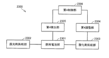
- a fuel cell unit Including a fuel cell unit, a reducing agent supplying unit for supplying a reducing agent to the anode electrode, an oxidizing agent supplying unit for supplying an oxidizing agent to the cathode electrode, a flow rate of the oxidizing agent supplied to the cathode electrode, and / or Alternatively, a fourth adjustment unit for adjusting the humidity, a fourth detection unit for detecting at least the relative humidity H ′ of the oxidant discharged from the cathode electrode, and a fourth adjustment unit and a fourth detection unit are connected.
- An alkaline fuel cell system comprising: a fourth control unit for controlling the flow rate and / or humidity of the oxidant by the fourth adjustment unit based on a detection result by the four detection unit.
- the fourth detection unit further detects a change amount ⁇ i per unit time of the current value flowing between the anode electrode and the cathode electrode of the alkaline fuel cell and a change amount ⁇ V per unit time of the output voltage value. It is preferable.
- the alkaline fuel cell system [D] adjusts the humidity of the cathode electrode, for example, by the following control.
- the fourth control unit controls the increase in the flow rate of the oxidant and / or the increase in the humidity of the oxidant, and the relative humidity H ′ detected by the fourth detection unit is a predetermined value B H ′ (where B H ′ is a value larger than 100% RH.) In the case where it is equal to or greater than this, the fourth control unit causes the fourth adjustment unit to reduce the flow rate of the oxidant and / or reduce the humidity of the oxidant. Control.
- the relative humidity H ′ is a percentage of the ratio of the weight of water contained in the oxidizer to the maximum value of the weight of water that the oxidizer placed at the temperature of the alkaline fuel cell can contain as water vapor.
- the value greater than 100% RH means that the water weight contained in the oxidizer is greater than the maximum water weight that the oxidizer placed at the temperature of the alkaline fuel cell can contain as water vapor. Become.
- Relative humidity H 'predetermined value A H of' is preferably in the range of 70-95 [% RH]
- the predetermined value B H ' is preferably in the range of 105 to 130 [% RH].
- the fourth adjusting unit reduces the flow rate of the oxidant and / or the oxidant. Control to reduce humidity.
- the predetermined value C i of ⁇ i is preferably in the range of ⁇ 50 to ⁇ 25 [mA / cm 2 ⁇ min] and the predetermined value D i is Preferably, it is in the range of +25 to +50 [mA / cm 2 ⁇ min].
- 'Predetermined value E H' of the relative humidity H is preferably in the range of 70-95 [% RH].
- the predetermined value G V of ⁇ V is preferably in the range of ⁇ 50 to ⁇ 2 [mV / min].
- the fourth control unit When ⁇ i detected by the fourth detection unit is smaller than the predetermined value C i , the fourth control unit causes the fourth adjustment unit to reduce the flow rate of the oxidant and / or reduce the humidity of the oxidant. And when the ⁇ i detected by the fourth detection unit is larger than the predetermined value D i , the fourth control unit causes the fourth adjustment unit to increase the flow rate of the oxidant and / or increase the humidity of the oxidant. Control is preferably performed.
- the alkaline fuel cell included in the alkaline fuel cell system of [D] may include an anode separator, an anode electrode, an anion conductive electrolyte membrane, a cathode electrode, and a cathode separator in this order.
- the oxidant supply unit can include, for example, a pipe that connects the oxidant supply source and the cathode separator of the alkaline fuel cell.
- the fourth adjustment unit may be a flow rate adjustment valve and / or a humidity controller provided in the pipe.
- the fuel cell unit can include two or more alkaline fuel cells electrically connected in series or in parallel.
- the reducing agent used in the alkaline fuel cell systems [A] to [D] of the present invention is preferably hydrogen gas, and the oxidizing agent is preferably air.
- ⁇ i reflecting the operating state of the alkaline fuel cell, and further ⁇ V and ⁇ R are detected and supplied to the anode electrode based on the detected ⁇ i.
- the humidity and flow rate of the reducing agent and / or oxidant supplied to the cathode electrode the humidity (water content) of the electrode (anode electrode and / or cathode electrode) of the alkaline fuel cell is optimally adjusted. Therefore, a high output voltage can be stably maintained.
- the relative humidity H of the reducing agent discharged from the anode electrode reflecting the operating state of the alkaline fuel cell and / or the cathode electrode.
- the humidity (water content) of the electrode (anode electrode and / or cathode electrode) of the alkaline fuel cell can be adjusted optimally, and thus a high output voltage can be stably maintained.
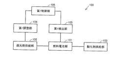
- FIG. 1 is a schematic diagram showing an example of the configuration of an alkaline fuel cell system 100 according to this embodiment (an example of the configuration of the alkaline fuel cell system [A]). .
- the alkaline fuel cell system 100 includes a fuel cell unit 101 including an alkaline fuel cell; a reductant supply unit 102 connected to the fuel cell unit 101 for supplying a reducing agent to the anode electrode of the alkaline fuel cell; An oxidant supply unit 103 connected to the unit 101 for supplying an oxidant to the cathode electrode of the alkaline fuel cell; a flow rate and / or humidity of the reductant connected to the reductant supply unit 102 and supplied to the anode electrode A first adjustment unit 104 for adjusting the fuel cell unit 101, and a first adjustment unit 104 for detecting at least a change amount ⁇ i per unit time of a current value flowing between an anode electrode and a cathode electrode of an alkaline fuel cell.
- Detection unit 105 includes a first control unit 106 for controlling the flow rate and / or adjustment of the humidity of the reducing agent by.
- the first detection unit 105 further detects a change amount ⁇ V per unit time of the output voltage value of the alkaline fuel cell and a change rate ⁇ R per unit time of the resistance value in addition to the change amount ⁇ i per unit time of the current value. It is preferable that
- the alkaline fuel cell system 100 having the above-described configuration, ⁇ i, and further, battery characteristics such as ⁇ V and ⁇ R are detected, and the reducing agent supplied to the anode electrode of the alkaline fuel cell in real time based on the detection result.
- the flow rate and / or humidity of the anode can be optimized, so that the humidity of the anode electrode is optimized.
- “flooding” that impedes the supply of the reducing agent to the anode electrode and the moisture content of the electrolyte membrane are low. Therefore, it is possible to prevent or improve “dry-up” that increases the anion conduction resistance. As a result, a high output voltage can be stably maintained.
- the fuel cell unit 101 is composed of an alkaline fuel cell.
- the alkaline fuel cell is a fuel cell having an anion conductive electrolyte membrane (anion exchange membrane) as an electrolyte membrane, and charge carriers are hydroxide ions (OH ⁇ ).
- the alkaline fuel cell includes a membrane electrode assembly (MEA) having an anode electrode, an anion conductive electrolyte membrane, and a cathode electrode in this order as a power generation main part.
- MEA membrane electrode assembly
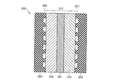
- FIG. 2 is a schematic cross-sectional view showing a preferred example of an alkaline fuel cell used in the alkaline fuel cell system of the present invention (the alkaline fuel cell system of this embodiment and other embodiments described later).
- 1 shows a single cell structure of a battery.
- the alkaline fuel cell 200 shown in FIG. 2 is laminated on the outer surface of the anode electrode 202 and the membrane electrode assembly (MEA) 210 having the anode electrode 202, the anion conductive electrolyte membrane 201 and the cathode electrode 203 in this order.
- An anode separator 204 and a cathode separator 205 stacked on the outer surface of the cathode electrode 203 are provided.
- a reducing agent channel 206 and an oxidizing agent channel 207 for introducing a reducing agent and an oxidizing agent to the anode electrode 202 and the cathode electrode 203, respectively.
- Anion-conducting electrolyte membrane As the anion-conducting electrolyte membrane 201, as long as it can conduct OH - ions and has an electrical insulation property to prevent a short circuit between the anode electrode 202 and the cathode electrode 203, although not particularly limited, an anion conductive solid polymer electrolyte membrane can be suitably used.
- the anion conductive solid polymer electrolyte membrane include, for example, perfluorosulfonic acid type, perfluorocarboxylic acid type, styrene vinyl benzene type, quaternary ammonium type solid polymer electrolyte membrane (anion exchange membrane). It is done.
- a membrane obtained by impregnating polyacrylic acid with a concentrated potassium hydroxide solution or an anion conductive solid oxide electrolyte membrane can also be used as the anion conductive electrolyte membrane 201.
- the anion conductive electrolyte membrane 201 preferably has an anion conductivity of 10 ⁇ 5 S / cm or more, and an electrolyte membrane having an anion conductivity of 10 ⁇ 3 S / cm or more, such as a perfluorosulfonic acid polymer electrolyte membrane. It is more preferable to use
- the thickness of the anion conductive electrolyte membrane 201 is usually 5 to 300 ⁇ m, preferably 10 to 200 ⁇ m.
- Anode electrode and cathode electrode An anode electrode 202 formed on one surface of the anion conductive electrolyte membrane 201 and a cathode electrode 203 formed on the other surface have a catalyst (an anode catalyst and a cathode catalyst, respectively) and an electrolyte. At least a catalyst layer (anode catalyst layer and cathode catalyst layer, respectively) composed of a porous layer containing (an anode electrolyte and a cathode electrolyte, respectively) is provided. These catalyst layers are laminated in contact with the surface of the anion conductive electrolyte membrane 201.
- the anode catalyst catalyzes a reaction that generates water and electrons from the reducing agent and OH ⁇ supplied to the anode electrode 202.
- the anode electrolyte has a function of conducting OH ⁇ conducted from the anion conductive electrolyte membrane 201 to the catalytic reaction site.
- the cathode catalyst catalyzes a reaction for generating OH ⁇ from the oxidant and water supplied to the cathode electrode 203 and the electrons transmitted from the anode electrode 202.
- the cathode electrolyte has a function of conducting the generated OH ⁇ to the anion conductive electrolyte membrane 201.
- anode catalyst and the cathode catalyst conventionally known ones can be used.
- the alloy is preferably an alloy containing at least two of platinum, iron, cobalt, and nickel.
- the anode catalyst and the cathode catalyst may be the same or different.
- the anode catalyst and the cathode catalyst are preferably those supported on a carrier, preferably a conductive carrier.
- a carrier preferably a conductive carrier.
- the conductive carrier include carbon black such as acetylene black, furnace black, channel black, and ketjen black, and conductive carbon particles such as graphite and activated carbon.
- carbon fibers such as vapor grown carbon fiber (VGCF), carbon nanotube, carbon nanowire, and the like can be used.
- the same electrolyte as that constituting the anion conductive solid polymer electrolyte membrane can be used.
- the content ratio of the catalyst and the electrolyte in the anode catalyst layer and the cathode catalyst layer is usually 5/1 to 1/4, preferably 3/1 to 1/3, based on weight.
- the anode electrode 202 and the cathode electrode 203 may each include an anode gas diffusion layer and a cathode gas diffusion layer laminated on the anode and the cathode catalyst layer. These gas diffusion layers have a function of diffusing a reducing agent or an oxidant supplied to the anode electrode 202 and the cathode electrode 203 in the plane, and a function of transferring electrons to and from the anode catalyst layer and the cathode catalyst layer. .
- the anode gas diffusion layer and the cathode gas diffusion layer can be porous layers having conductivity, specifically, for example, carbon paper; carbon cloth; epoxy resin film containing carbon particles; metal or alloy It can be a foam, a sintered body, a fiber nonwoven fabric or the like.
- the thickness of the anode gas diffusion layer and the cathode gas diffusion layer is preferably 10 ⁇ m or more in order to reduce the diffusion resistance of the reducing agent or oxidizing agent in the direction perpendicular to the thickness direction (in-plane direction). In order to reduce the diffusion resistance in the thickness direction, it is preferably 1 mm or less.
- the thickness of the anode gas diffusion layer and the cathode gas diffusion layer is more preferably 100 to 500 ⁇ m.
- the alkaline fuel cell is usually disposed on the anode electrode 202 of the membrane electrode assembly 210 to introduce a reducing agent into the anode electrode 202.
- a cathode separator 205 is provided on the anode separator 204 and the cathode electrode 203 for introducing an oxidant into the cathode electrode 203.
- Each of the anode separator 204 and the cathode separator 205 is provided with a channel (reducing agent channel 206 and oxidant channel 207, respectively) formed of a groove for circulating a reducing agent or an oxidizing agent on the surface on the membrane electrode assembly 210 side. Can be things.
- the flow path can be composed of one or two or more grooves, and the shape is not particularly limited, and can be a line shape, a serpentine shape, or the like.
- a reducing agent supply unit which will be described later
- the reducing agent channel 206 By connecting a reducing agent supply unit, which will be described later, and the reducing agent channel 206, the reducing agent can be circulated through the reducing agent channel 206 and supplied to the anode 202.
- an oxidant supply unit which will be described later, and the oxidant flow path 207, the oxidant can be circulated through the oxidant flow path 207 and supplied to the cathode electrode 203.
- the material of the anode separator 204 and the cathode separator 205 is not particularly limited.
- conductive materials such as carbon materials, conductive polymers, various metals, alloys such as stainless steel, and non-conductive materials such as various plastic materials. Materials.
- a conductive material because a current collecting function can be imparted to the anode separator 204 and the cathode separator 205.
- a current collector current collection layer
- a current collector current collection layer
- the anode separator 204 and the cathode separator 205 may be made of a conductive material, and a current collector may be provided separately between the outside or the membrane electrode assembly 210 and each separator.
- a current collector may be provided separately between the outside or the membrane electrode assembly 210 and each separator.
- H 2 gas for example, H 2 gas, hydrocarbon gas, ammonia gas, or the like can be used as the reducing agent (fuel).
- reducing agent fuel
- the oxidizing agent for example, O 2 gas or a gas containing O 2 such as air can be used. Of these, air is preferably used.
- the fuel cell unit 101 (and a fuel cell unit included in an alkaline fuel cell system according to another embodiment described later) can include two or more alkaline fuel cells.
- Two or more alkaline fuel cells may be electrically connected to each other in series, may be electrically connected in parallel, or may include an electrical connection between them.
- a fuel cell stack in which a plurality of single cells as shown in FIG. 2 are stacked in series, or a plurality of single cells as shown in FIG. 2 are arranged on the same plane, and these are electrically connected in parallel.
- a planar integrated battery and a fuel cell stack in which a plurality of the planar integrated batteries are stacked in series can be exemplified.
- the reducing agent supply unit 102 is a part for supplying the reducing agent to the anode electrode of the alkaline fuel cell.
- the reducing agent supply unit reducing agent storage tank or the like
- the anode side more specifically, the alkaline fuel cell.
- it may be a pipe connecting the reducing agent flow path of the anode separator.
- the oxidant supply unit 103 is a part for supplying an oxidant to the cathode electrode of the alkaline fuel cell.
- the oxidant supply source oxidant storage tank or the like
- the cathode side of the alkaline fuel cell More specifically, it may be a pipe connecting the oxidant flow path of the cathode separator.
- the material of the reducing agent supply unit 102 and the oxidizing agent supply unit 103 is not particularly limited, and may be a polymer material, a metal, an alloy, or the like.
- the reducing agent supply unit 102 and the oxidizing agent supply unit 103 may be provided with a pump or a fan that promotes the flow of the reducing agent or the oxidizing agent, as necessary.
- the first adjustment unit 104 is a part for adjusting the flow rate or humidity (relative humidity) of the reducing agent flowing through the reducing agent supply unit 102 (to be supplied to the anode electrode), or both, Connected to the reducing agent supply unit 102.
- the first adjustment unit 104 may be, for example, a flow rate adjustment valve that adjusts the flow rate of the reducing agent, a humidity controller that adjusts the humidity of the reducing agent, or both, provided in the reducing agent supply unit 102. It can.
- the flow control valve and the humidity controller may be conventionally known ones.
- the humidity of the reducing agent can be increased or decreased by adjusting the temperature of the water bath.
- An apparatus that comprises a porous metal (such as foam metal) containing water in the pores, and humidifies by passing a reducing agent through the pores. Also in this apparatus, the humidity of the reducing agent can be increased or decreased by adjusting the temperature of the porous metal.
- a porous metal such as foam metal
- the first adjustment unit 104 detects the temperature of the humidity controller (water temperature, temperature of the porous metal, etc.). It is preferable that the fuel cell unit 101 includes temperature detection means (temperature sensor) for detecting the temperature inside the alkaline fuel cell (particularly the anode electrode) while including temperature detection means (temperature sensor). In this case, the 1st control part 106 mentioned later controls so that a humidity controller may perform desired temperature adjustment based on the temperature detection result by both temperature detection means. Specifically, the humidity of the reducing agent can be increased / decreased by increasing / decreasing the temperature of the humidity controller.
- the humidity adjustment of the reducing agent by the first adjusting unit 104 can be performed within a suitable range.
- the first adjustment unit 104 may optionally include a detector that detects the flow rate and / or humidity (that is, inlet side humidity) of the reducing agent after adjustment (or before and after adjustment). In this case, by referring to the detection result of the detector, the flow rate and / or humidity of the reducing agent by the first adjustment unit 104 can be adjusted within a suitable range.
- the first detection unit 105 is a part connected to the fuel cell unit 101 for detecting battery characteristics of the alkaline fuel cell.
- the first detection unit 105 detects at least a change amount ⁇ i per unit time of a current value flowing between the anode electrode and the cathode electrode as a battery characteristic of the alkaline fuel cell.
- ⁇ i is a parameter for determining whether or not the alkaline fuel cell is moving in a direction in which flooding or dry-up occurs. Therefore, flooding and dry-up can be prevented beforehand by detecting ⁇ i and appropriately adjusting the humidity of the reducing agent accordingly.
- ⁇ i (i 1 ⁇ i 0 ) / (t 1 ⁇ t 0 ) [mA / cm 2 ⁇ min] (7)
- I 0 is the current amount (mA / cm 2 ) at the measurement start time t 0 (min), and i 1 is the current amount at the measurement end time t 1 .
- the current amounts i 0 and i 1 can be measured using a commonly used ammeter, tester, or the like.
- an ammeter that can be directly incorporated in the circuit and can always measure the amount of current is used.
- the first detection unit 105 uses a change amount ⁇ V per unit time of the output voltage value of the alkaline fuel cell as a parameter for determining whether flooding or dry-up has already occurred or whether such a sign is recognized. It is preferable that the rate of change ⁇ R per unit time of the resistance value is further detected. ⁇ V is an effective parameter for determining flooding, and ⁇ R is an effective parameter for determining dry-up.
- ⁇ V (V 1 ⁇ V 0 ) / (t 1 ⁇ t 0 ) [mV / min] (8)
- V 0 is the voltage amount (mV) at the measurement start time t 0 (min)
- V 1 is the voltage amount at the measurement end time t 1 .
- the voltage amounts V 0 and V 1 can be measured using a commonly used voltmeter, tester, or the like. Preferably, a voltmeter that can be directly measured in a circuit and can be measured at all times is used.
- the resistance values R 0 and R 1 can be measured by an electrochemical impedance method (AC impedance method) or a current interruption method.
- an electronic load device (potential galvanostat) and a frequency response analyzer (FRA) are connected to a fuel cell, and a predetermined frequency is transmitted from the transmitter built in the device to the fuel cell.
- Outputs sine wave signal, voltage and current signal input from fuel cell is converted in the applied frequency domain to obtain electrochemical impedance, and from the contact point between the real axis in the complex plane and the obtained impedance spectrum
- the current interruption method uses an electronic load device connected to the fuel cell, the ohmic loss becomes zero when the current is interrupted, and the operating voltage of the fuel cell changes instantaneously (voltage increase). This is a method of calculating a resistance value from a current / voltage waveform obtained when a current is interrupted to a battery.
- the resistance measured in the present invention obtained by the electrochemical impedance method and the current interruption method described above is generally referred to as “cell resistance”, “solution resistance”, or “membrane resistance”, and the anion conduction constituting an alkaline fuel cell.
- the cell resistance contributes particularly to the resistance of the anion conductive electrolyte membrane, and the resistance value of the anion conductive electrolyte membrane depends greatly on the dry state of the anion conductive electrolyte membrane.
- resistances (resistances such as electrodes and separators) other than the anion conductive electrolyte membrane show a substantially constant value regardless of the dry state of the anion conductive electrolyte membrane. Therefore, in the present embodiment, the dry state of the anion conductive electrolyte membrane is grasped from the cell resistance value obtained by the electrochemical impedance method or the current interruption method.
- the rate of change ( ⁇ R) per unit time of the cell resistance value is greater than a predetermined value C R (where C R is a positive value)
- the resistance of the anion conductive electrolyte membrane is Also, it is evaluated that the rate of change per unit time shows a positive value (resistance increases), and it is determined that “dry-up” occurs in the anion conductive electrolyte membrane.
- the fuel cell unit 101 (and a fuel cell unit included in an alkaline fuel cell system according to another embodiment described later) can include two or more alkaline fuel cells.
- ⁇ i, or ⁇ i, ⁇ V, and ⁇ R values may be measured for each alkaline fuel cell, but two or more alkaline fuel cells are used as one from the viewpoint of connection relationship and controllability. It is preferable to measure ⁇ i, or ⁇ i, ⁇ V, and ⁇ R as a whole, considering one fuel cell.
- the first control unit 106 Based on the detection result signal ( ⁇ i, or ⁇ i, ⁇ V, and ⁇ R values) output from the first detection unit 105, the first control unit 106 determines the flow rate and / or humidity of the reducing agent by the first adjustment unit 104. This is a part that controls the adjustment, and is connected to the first adjustment unit 104 and the first detection unit 105. When the 1st adjustment part 104 and the fuel cell part 101 are provided with the above-mentioned temperature detection means, these are also connected and the temperature adjustment by a humidity controller is controlled based on the detection signal from a temperature detection means.
- the first control unit 106 sequentially receives the detection result signal output from the first detection unit 105 according to a flow described later, and receives the received ⁇ i, ⁇ V, ⁇ R values, and a predetermined value set in advance. (This point will be described in detail later). Based on the determination result, the first adjustment unit 104 is controlled so that the humidity of the anode electrode is optimized.
- the first control unit 106 is not particularly limited, and for example, a personal computer can be used.
- the alkaline fuel cell system of this embodiment (and alkaline fuel cell systems of other embodiments described later) can include other components other than those described above.
- an alkaline fuel cell system usually has a reducing agent discharge part for discharging the reducing agent that has passed through the anode separator of the alkaline fuel cell to the outside, and an oxidant that has passed through the cathode separator to the outside.
- An oxidizer discharge part is provided.
- the reducing agent discharge part and the oxidant discharge part can be connected to the outlet side end part of the reducing agent channel of the anode separator and the oxidizing agent channel of the cathode separator, respectively.
- a dilution part for diluting the reducing agent discharged from the fuel cell part to the extent that it can be released, or a recycling pipe for returning the reducing agent discharged from the fuel cell part to the reducing agent supply part is provided. Also good.
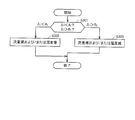
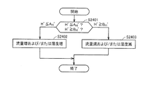
- FIG. 3 is a flowchart showing an example of anode pole humidity control by the alkaline fuel cell system 100 of the present embodiment.
- ⁇ i is detected by the first detection unit 105.
- whether the detected ⁇ i value is smaller than a predetermined value A i (where A i is a negative value) and a predetermined value B i (where B i is a positive value).
- a i where A i is a negative value
- B i where B i is a positive value
- control is performed to reduce the flow rate of the reducing agent and / or increase the humidity of the reducing agent (step S302).
- control is based on the determination that the determination result “ ⁇ i ⁇ A i ” is “in the direction of causing dry-up” in the present embodiment. This is because “ ⁇ i ⁇ A i (decrease in the current value)” results in a decrease in the amount of water generated by the reaction at the anode electrode, and hence a decrease in humidity at the anode electrode, and as a result, dry-up is likely to occur.
- control is performed to increase the flow rate of the reducing agent and / or reduce the humidity of the reducing agent (step S303).
- control is based on the determination that the determination result “ ⁇ i> B i ” is “in the direction in which flooding occurs” in the present embodiment. This is because “ ⁇ i> B i (increase in current value)” causes an increase in the amount of water generated by the reaction at the anode electrode, and hence an increase in humidity at the anode electrode, and as a result, flooding is likely to occur.
- the humidity control of the anode electrode in this example can be applied to prevent the occurrence of dry-up and flooding. That is, the humidity control of this example performs feedforward control based on the detection result of ⁇ i.
- the humidity control of the anode electrode in this example is advantageous in that it can perform quick control because only the current change needs to be detected.
- the humidity control of the anode electrode may be performed only by adjusting the flow rate of the reducing agent, may be performed only by adjusting the humidity of the reducing agent, or may be performed by adjusting both the flow rate and the humidity (described later). The same applies to other humidity control flows). Adjustment of the flow rate of the reducing agent is advantageous in that the humidity control of the anode electrode can be performed easily and quickly. On the other hand, the humidity adjustment of the reducing agent is advantageous in that the humidity control of the anode electrode can be performed with high accuracy.
- the predetermined value A i is preferably in the range of ⁇ 50 to ⁇ 25 [mA / cm 2 ⁇ min], and more preferably in the range of ⁇ 40 to ⁇ 30 [mA / cm 2 ⁇ min].
- the predetermined value Bi is preferably in the range of +25 to +50 [mA / cm 2 ⁇ min], and more preferably in the range of +30 to +40 [mA / cm 2 ⁇ min].
- the flow rate of the reducing agent is increased in order to reduce the humidity of the anode electrode, it is preferable to avoid increasing the flow rate of the reducing agent in consideration of the utilization efficiency of the reducing agent.
- the flow rate of the reducing agent in order to increase the humidity of the anode electrode, avoid reducing the flow rate of the reducing agent to an extremely low level because it may not be possible to supply the required amount of power. Is preferred.
- the humidity of the reducing agent inlet side humidity
- the humidity on the inlet side of the anode electrode becomes extremely low, resulting in an extreme humidity difference between the inlet side and the outlet side of the anode electrode, which in turn causes an extreme difference in the reaction amount, resulting in deterioration of the fuel cell. This is because it becomes easier.
- the adjustment of the flow rate and / or humidity of the reducing agent within such an appropriate range is, for example, based on the detection result of the detector that detects the flow rate and / or humidity of the reducing agent after the adjustment (or before and after the adjustment) described above. Can be achieved by control based on.
- the above matters regarding the flow rate of the reducing agent and the lower limit value and the upper limit value of the humidity also apply to other anode pole humidity control flows described later.
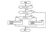
- FIG. 4 is a flowchart showing another example of the humidity control of the anode electrode by the alkaline fuel cell system 100 of the present embodiment.
- ⁇ i is detected by the first detection unit 105.
- the first control unit 106 determines whether or not the detected ⁇ i value is within the range of A i to B i including 0 (A i and B i have the same meaning as described above). (Step S401).
- the first control unit 106 performs control so that the first detection unit 105 detects ⁇ R (note that ⁇ i is not within the range of A i to B i.
- the above-mentioned anode extreme humidity control flow 1 may be carried out). Then, the first control unit 106 determines whether or not the detected ⁇ R value is equal to or less than a predetermined value C R (where C R is a positive value) (step S402). Based on the determination result, the first control unit 106 controls the first adjustment unit 104 and the like as follows.
- [1] ⁇ R is the case is less than a predetermined value C R
- the first control unit 106, first detector 105 is controlled to detect the [Delta] V.
- the first controller 106 determines whether or not the detected ⁇ V value is less than a predetermined value D v (where D v is a negative value) (step S403). If the detected ⁇ V is less than the predetermined value D v , control is performed to increase the flow rate of the reducing agent and / or reduce the humidity of the reducing agent (step S404). In this embodiment, such control is determined as “ ⁇ R ⁇ C R ” and the subsequent determination result “ ⁇ V ⁇ D V ” that “the voltage value is not reduced by dry-up but by flooding”. Based on that. That is, the determination result “ ⁇ V ⁇ D V ” (decrease in voltage value) means that dry-up or flooding occurs or tends to occur, but the determination result “ ⁇ R ⁇ C R ”. Means that no dry-up (or tendency) has occurred.
- the determination result of “ ⁇ V ⁇ D V ” is that the voltage value has increased and it is determined that dry-up or flooding (or such a tendency) has not occurred.
- ⁇ R is larger than the predetermined value C R is controlled to perform the increase of humidity reduction and / or a reducing agent of the flow rate of the reducing agent (step S405).
- control is based on the determination that “ ⁇ R> C R ” is determined to be “dry up (or its tendency)”.
- the predetermined value C R is preferably in the range of +5 to +20 [% / min], and more preferably in the range of +5 to +10 [% / min].
- the predetermined value D v is preferably in the range of ⁇ 50 to ⁇ 2 [mV / min], more preferably in the range of ⁇ 30 to ⁇ 10 [mV / min].
- the humidity control of this example in addition to ⁇ i, ⁇ R of the alkaline fuel cell and if necessary ⁇ V are detected in this order to optimize the humidity of the anode electrode. By detecting these battery characteristics in real time, it is possible to grasp the humidity state of the anode electrode (whether dry-up or flooding has occurred), and the anode electrode humidity can be optimally controlled accordingly. .
- the humidity control in this example performs feedback control based on the detection results of ⁇ R and ⁇ V.
- it is determined in step S402 that “ ⁇ R ⁇ C R ” is not satisfied (that is, “ ⁇ R> C R ”) detection of ⁇ V is unnecessary, and the anode is relatively simple.
- the pole humidity can be optimized.
- FIG. 5 is a flowchart showing another example of the humidity control of the anode electrode by the alkaline fuel cell system 100 of the present embodiment.
- ⁇ i is detected by the first detector 105.
- the first control unit 106 determines whether or not the detected ⁇ i value is within the range of A i to B i including 0 (A i and B i have the same meaning as described above). (Step S501).
- the first control unit 106 performs control so that the first detection unit 105 detects ⁇ V (note that ⁇ i is not within the range of A i to B i.
- the above-mentioned anode extreme humidity control flow 1 may be carried out). Then, the first controller 106 determines whether or not the detected ⁇ V value is less than a predetermined value D v (D v has the same meaning as described above) (step S502). Based on the determination result, the first control unit 106 controls the first adjustment unit 104 and the like as follows.
- the first control unit 106 controls the first detection unit 105 to detect ⁇ R. Then, the first control unit 106 determines whether or not the detected ⁇ R value is equal to or less than a predetermined value C R (C R has the same meaning as described above) (step S503). It detected ⁇ R is the case of less than the predetermined value C R is controlled to perform a reduction of the humidity increase and / or a reducing agent of the flow rate of the reducing agent (step S504). In this embodiment, in this embodiment, the determination result of “ ⁇ V ⁇ D V ” and subsequent “ ⁇ R ⁇ C R ” is determined as “the decrease in voltage value is not caused by dry-up but by flooding”.
- the determination result “ ⁇ V ⁇ D V ” (decrease in voltage value) means that dry-up or flooding occurs or tends to occur, but the determination result “ ⁇ R ⁇ C R ”. Means that no dry-up (or tendency) has occurred.
- the detected ⁇ R value at step S503 is C when R is greater than controls to perform the increase of humidity reduction and / or a reducing agent of the flow rate of the reducing agent (step S505).
- control is based on the determination that “ ⁇ R> C R ” is determined to be “dry up (or its tendency)”.
- the humidity control of this example in addition to ⁇ i, ⁇ V of the alkaline fuel cell and if necessary ⁇ R are detected in this order to optimize the humidity of the anode electrode. By detecting these battery characteristics in real time, it is possible to grasp the humidity state of the anode electrode (whether dry-up or flooding has occurred), and the anode electrode humidity can be optimally controlled accordingly. .
- the humidity control in this example performs feedback control based on the detection results of ⁇ R and ⁇ V.
- ⁇ V ⁇ D V if it is determined in step S502 that “ ⁇ V ⁇ D V ” is not satisfied (that is, “ ⁇ V ⁇ D V ”), detection of ⁇ R is unnecessary, and the anode is relatively simple.
- the pole humidity can be optimized.
- the detection of ⁇ V is simpler than ⁇ R, and the humidity control of this example is advantageous also in this respect.
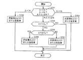
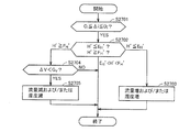
- Anode pole humidity control flow 4) 6 and 7 are flowcharts showing another example of anode pole humidity control by the alkaline fuel cell system 100 of the present embodiment.
- the anode pole humidity control of this example is a combination of the anode pole humidity control flow 1 and the anode pole humidity control flow 2 or 3.
- the control flow shown in FIG. 6 is a combination of the anode extreme humidity control flow 1 and the anode extreme humidity control flow 2
- the control flow shown in FIG. 7 is the combination of the anode extreme humidity control flow 1 and the anode extreme humidity control flow 3. It is a combination.
- step S301 when it is determined that “A i ⁇ ⁇ i ⁇ B i ” in step S301 (S601 or S701 in this example) of the anode extreme humidity control flow 1, the anode extreme humidity control flow 2 or 3
- the control flow is executed.
- the first control unit 106 controls the first adjustment unit 104 and the like as follows.
- Control flow shown in FIG. 6 (combination of anode pole humidity control flows 1 and 2) [1] If ⁇ i is smaller than A i , control is performed to reduce the flow rate of the reducing agent and / or increase the humidity of the reducing agent (step S602).
- [2] ⁇ i when is greater than B i is controlled to perform a reduction of the humidity increase and / or a reducing agent of the flow rate of the reducing agent (step S603).
- step S604 If ⁇ i is in the range of A i ⁇ B i, either the first control unit 106, first detector 105 is controlled so as to detect the [Delta] R, detected [Delta] R is equal to or less than C R No is determined by the first control unit 106 (step S604). Based on the determination result, the first control unit 106 controls the first adjustment unit 104 and the like as follows.
- the first control unit 106 When ⁇ R is less than C R, the first control unit 106, first detector 105 is controlled to detect the [Delta] V. Then, the first control unit 106 determines whether or not the detected ⁇ V value is less than D v (step S605). If the detected ⁇ V is less than D v , control is performed to increase the flow rate of the reducing agent and / or reduce the humidity of the reducing agent (step S606). On the other hand, if the detected ⁇ V is greater than or equal to D V, the adjustment of the flow rate and / or humidity of the reducing agent is not required.
- [2] ⁇ i when is greater than B i is controlled to perform a reduction of the humidity increase and / or a reducing agent of the flow rate of the reducing agent (step S703).
- the first control unit 106 controls the first detection unit 105 to detect ⁇ V, and the detected ⁇ V value is less than D v. Is determined by the first control unit 106 (step S704). Based on the determination result, the first control unit 106 controls the first adjustment unit 104 and the like as follows.
- the first control unit 106 controls the first detection unit 105 to detect ⁇ R. Then, the detected ⁇ R value is equal to or less than C R is determined by the first control unit 106 (step S705). Detected ⁇ R is when: C R is controlled to perform a reduction of the humidity increase and / or a reducing agent of the flow rate of the reducing agent (step S706). On the other hand, the detected ⁇ R is C when R is greater than controls to perform the increase of humidity reduction and / or a reducing agent of the flow rate of the reducing agent (step S707).
- the humidity control in this example is a combination of two control methods, ie, feedforward control based on the detection result of ⁇ i and feedback control based on the detection result of ⁇ R or ⁇ V.
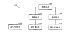
- FIG. 8 is a schematic diagram showing an example of the configuration of an alkaline fuel cell system 800 according to this embodiment (an example of the configuration of the alkaline fuel cell system [B]). .
- the alkaline fuel cell system 800 includes a fuel cell unit 801 including an alkaline fuel cell; a reducing agent supply unit 802 connected to the fuel cell unit 801 and for supplying a reducing agent to the anode electrode of the alkaline fuel cell; An oxidant supply unit 803 for supplying an oxidant to the cathode of the alkaline fuel cell; connected to the unit 801; a flow rate and / or humidity of the oxidant connected to the oxidant supply unit 803 and supplied to the cathode A second adjusting unit 804 for adjusting the fuel cell unit 801 for detecting at least a change amount ⁇ i per unit time of a current value flowing between the anode and the cathode of the alkaline fuel cell.
- 04 includes a second control unit 806 for controlling the flow rate and / or adjustment of the humidity of the oxidizing agent by.
- the second detection unit 805 further detects a change amount ⁇ V per unit time of the output voltage value of the alkaline fuel cell and a change rate ⁇ R per unit time of the resistance value in addition to the change amount ⁇ i per unit time of the current value. It is preferable that
- the alkaline fuel cell system 800 configured as described above, ⁇ i, and further, battery characteristics such as ⁇ V and ⁇ R are detected, and the oxidant supplied to the cathode electrode of the alkaline fuel cell in real time based on the detection result.
- the flow rate and / or humidity of the cathode electrode can be optimized, so that the humidity of the cathode electrode is optimized.
- the above-described “flooding” that impedes the supply of the oxidant to the cathode electrode and the moisture content of the electrolyte membrane is low. Therefore, it is possible to prevent or improve “dry-up” that increases the anion conduction resistance. As a result, a high output voltage can be stably maintained.
- the fuel cell unit 801, the reducing agent supply unit 802, and the oxidant supply unit 803 included in the alkaline fuel cell system 800 according to the present embodiment are the fuel cell units included in the alkaline fuel cell system 100 according to the first embodiment, respectively.
- 101, the reducing agent supply unit 102, and the oxidant supply unit 103 can be configured in the same manner, and the matters described for the fuel cell unit 101, the reducing agent supply unit 102, and the oxidant supply unit 103 are the fuel cell unit 801, the reduction agent
- the agent supply unit 802 and the oxidant supply unit 803 are also cited.
- the second adjustment unit 804 is a part for adjusting the flow rate or humidity (relative humidity) of the oxidant flowing through the oxidant supply unit 803 (to be supplied to the cathode electrode), or both, Connected to the oxidant supply unit 803.
- the second adjustment unit 804 may be, for example, a flow rate adjustment valve that adjusts the flow rate of the oxidant, a humidity controller that adjusts the humidity of the oxidant, or both, provided in the oxidant supply unit 803. it can.
- the flow control valve and the humidity controller may be conventionally known ones.
- the humidity of the oxidant can be increased or decreased by adjusting the temperature of the water bath.
- An apparatus that includes a porous metal (such as foam metal) containing water in the pores and humidifies the oxidant by passing through the pores. Also in this apparatus, the humidity of the oxidizing agent can be increased or decreased by adjusting the temperature of the porous metal.
- a porous metal such as foam metal
- the second adjustment unit 804 detects the temperature of the humidity controller (water temperature, temperature of the porous metal, etc.). It is preferable that the fuel cell unit 801 includes temperature detection means (temperature sensor) for detecting the temperature in the alkaline fuel cell (particularly the cathode electrode) while including temperature detection means (temperature sensor). In this case, the second control unit 806, which will be described later, controls the humidity controller to perform a desired temperature adjustment based on the temperature detection results of both temperature detection means. Specifically, the humidity of the oxidizer can be increased / decreased by increasing / decreasing the temperature of the humidity controller.
- Oxidant humidity [saturated vapor pressure of water at the temperature of the second adjustment unit (humidifier)] / [saturated vapor pressure of water at the temperature of the alkaline fuel cell] (10) Defined by
- the saturated vapor pressure of water at a certain temperature T is obtained by referring to a table in which the saturated vapor pressure of water at each temperature is recorded in the second control unit 806 or approximated by the above formula (6 ) Can be used for calculation.
- the humidity adjustment of the oxidant by the second adjustment unit 804 can be performed within a suitable range.
- the second adjustment unit 804 may optionally have a detector that detects the flow rate and / or humidity (that is, inlet side humidity) of the oxidant after adjustment (or before and after adjustment). In this case, by referring to the detection result of the detector, the flow rate and / or humidity of the oxidizing agent by the second adjustment unit 804 can be adjusted within a suitable range.
- the second detection unit 805 is a part for detecting cell characteristics of the alkaline fuel cell connected to the fuel cell unit 801.
- the second detection unit 805 detects at least a change amount ⁇ i per unit time of the current value flowing between the anode electrode and the cathode electrode as the battery characteristics of the alkaline fuel cell.
- ⁇ i is a parameter for determining whether or not the alkaline fuel cell is moving in a direction in which flooding or dry-up occurs. Therefore, flooding and dry-up can be prevented beforehand by detecting ⁇ i and appropriately adjusting the humidity of the oxidant accordingly.
- ⁇ i is expressed by the above formula (7).
- the second detection unit 805 uses a change amount ⁇ V per unit time of the output voltage value of the alkaline fuel cell as a parameter for determining whether flooding or dry-up has already occurred or whether such a sign is recognized. It is preferable that the rate of change ⁇ R per unit time of the resistance value is further detected.
- ⁇ V is an effective parameter for determining flooding
- ⁇ R is an effective parameter for determining dry-up.
- ⁇ V and ⁇ R are expressed by the above formulas (8) and (9), respectively, and the resistance values R 0 and R 1 in the above formula (9) are the electrochemical impedance method (AC impedance method) or current. It can be measured by the blocking method.
- the dry state of the anion conductive electrolyte membrane is grasped from the cell resistance value obtained by the electrochemical impedance method or the current interruption method. That is, in this embodiment, when the rate of change ( ⁇ R) per unit time of the cell resistance value is greater than a predetermined value C R (where C R is a positive value), the resistance of the anion conductive electrolyte membrane is Also, it is evaluated that the rate of change per unit time shows a positive value (resistance increases), and it is determined that “dry-up” occurs in the anion conductive electrolyte membrane.
- the second control unit 806 Based on the detection result signal ( ⁇ i or ⁇ i, ⁇ V, and ⁇ R values) output from the second detection unit 805, the second control unit 806 determines the flow rate and / or humidity of the oxidant by the second adjustment unit 804. This is a part that controls the adjustment, and is connected to the second adjustment unit 804 and the second detection unit 805. When the 2nd adjustment part 804 and the fuel cell part 801 are provided with the above-mentioned temperature detection means, these are also connected and based on the detection signal from a temperature detection means, the temperature adjustment by a humidity controller is controlled.
- the second control unit 806 sequentially receives the detection result signal output from the second detection unit 805 according to a flow described later, and receives the received ⁇ i, ⁇ V, ⁇ R values, and a predetermined value set in advance. (This point will be described in detail later). Based on the determination result, the second adjustment unit 804 is controlled so that the humidity of the cathode electrode is optimized.
- the second controller 806 is not particularly limited, and for example, a personal computer can be used.
- FIG. 9 is a flowchart showing an example of cathode pole humidity control by the alkaline fuel cell system 800 of the present embodiment.
- ⁇ i is detected by the second detection unit 805.
- B i a predetermined value
- the second control unit 806 determines whether it is larger (that is, whether it is not within the range of A i to B i including 0) (step S901). Based on the determination result, the second control unit 806 controls the second adjustment unit 804 as follows.
- control is performed to reduce the flow rate of the oxidant and / or reduce the humidity of the oxidant (step S902).
- control is based on the determination that the determination result “ ⁇ i ⁇ A i ” is “in the direction in which flooding occurs” in the present embodiment. This is because “ ⁇ i ⁇ A i (decrease in the current value)” results in a decrease in the amount of water consumed by the reaction at the cathode electrode, and thus an increase in the humidity of the cathode electrode, and as a result, flooding is likely to occur.
- control is performed to increase the flow rate of the oxidant and / or increase the humidity of the oxidant (step S903).
- Such control is based on the determination that the determination result “ ⁇ i> B i ” is “in the direction of causing dry-up” in the present embodiment. This is because “ ⁇ i> B i (increase in current value)” causes an increase in the amount of water consumed by the reaction at the cathode electrode, and hence a decrease in humidity at the cathode electrode, and as a result, dry-up is likely to occur.
- the humidity control of the cathode electrode in this example can be applied to prevent the occurrence of dry-up and flooding. That is, the humidity control of this example performs feedforward control based on the detection result of ⁇ i. Moreover, the humidity control of the cathode electrode in this example is advantageous in that it can perform quick control because it is only necessary to detect a change in current.
- the humidity control of the cathode electrode may be performed only by adjusting the flow rate of the oxidant, may be performed only by adjusting the humidity of the oxidant, or may be performed by adjusting both the flow rate and the humidity (described later). The same applies to other humidity control flows). Adjusting the flow rate of the oxidant is advantageous in that the humidity control of the cathode electrode can be easily and quickly performed. On the other hand, the humidity adjustment of the oxidizing agent is advantageous in that the humidity control of the cathode electrode can be performed with high accuracy.
- the predetermined value A i is preferably in the range of ⁇ 50 to ⁇ 25 [mA / cm 2 ⁇ min], and more preferably in the range of ⁇ 40 to ⁇ 30 [mA / cm 2 ⁇ min].
- the predetermined value Bi is preferably in the range of +25 to +50 [mA / cm 2 ⁇ min], and more preferably in the range of +30 to +40 [mA / cm 2 ⁇ min].
- the cathode humidity control of this example if the detected ⁇ i value is within the range of A i to B i , it is determined that dry-up and flooding will not occur for at least a while, and the next ⁇ i is detected.
- the second adjusting unit 804 may not adjust the flow rate and / or humidity of the oxidant until dryness or flooding occurs even when the ⁇ i value is within the range of A i to B i . Since there is a possibility, it is preferable to continue the cathode pole humidity control flow 2 or 3 described later (see cathode pole humidity control flow 4).
- the power loss of the auxiliary equipment increases when an auxiliary equipment such as a fan is used to supply the oxidizer. It is preferable to avoid excessively increasing the flow rate of the agent.
- an auxiliary equipment such as a fan is used to supply the oxidizer.
- when reducing the flow rate of the oxidant in order to reduce the humidity of the cathode avoid reducing the flow rate of the oxidant to an extremely low level because the required amount of power may not be supplied. Is preferred.
- the humidity of the oxidant is increased in order to increase the humidity of the cathode electrode, it is preferable to avoid excessively increasing the humidity of the oxidant.
- An extremely high humidity on the cathode inlet side causes an extreme humidity difference between the cathode inlet side and the outlet side, which in turn causes an extreme difference in the reaction amount, resulting in deterioration of the fuel cell. This is because it becomes easier.
- the adjustment of the flow rate and / or humidity of the oxidant within such an appropriate range is, for example, based on the detection result of the detector that detects the flow rate and / or humidity of the oxidant after the adjustment described above (or before and after the adjustment). Can be achieved by control based on.
- the matters regarding the lower limit value and the upper limit value of the oxidant flow rate and humidity described above also apply to other cathode pole humidity control flows described later.
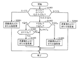
- FIG. 10 is a flowchart showing another example of the humidity control of the cathode electrode by the alkaline fuel cell system 800 of the present embodiment.
- ⁇ i is detected by the second detection unit 805.
- the second control unit 806 determines whether or not the detected ⁇ i value is within the range of A i to B i including 0 (A i and B i have the same meaning as described above). (Step S1001).
- the second control unit 806 controls the second detection unit 805 to detect ⁇ R (note that ⁇ i is not within the range of A i to B i.
- the cathode pole humidity control flow 1 may be performed). Then, the second control unit 806 determines whether or not the detected ⁇ R value is equal to or less than a predetermined value C R (where C R is a positive value) (step S1002). Based on the determination result, the second control unit 806 controls the second adjustment unit 804 and the like as follows.
- [1] ⁇ R is the case is less than a predetermined value C R
- the second control unit 806, second detection unit 805 is controlled to detect the [Delta] V.
- the second control unit 806 determines whether or not the detected ⁇ V value is less than a predetermined value D v (where D v is a negative value) (step S1003).
- D v is a predetermined value
- control is performed to reduce the flow rate of the oxidant and / or reduce the humidity of the oxidant (step S1004).
- such control is determined as “ ⁇ R ⁇ C R ” and the subsequent determination result “ ⁇ V ⁇ D V ” that “the voltage value is not reduced by dry-up but by flooding”.
- the determination result “ ⁇ V ⁇ D V ” (decrease in voltage value) means that dry-up or flooding occurs or tends to occur, but the determination result “ ⁇ R ⁇ C R ”. Means that no dry-up (or tendency) has occurred.
- the determination result of “ ⁇ V ⁇ D V ” is that the voltage value has increased and it is determined that dry-up or flooding (or such a tendency) has not occurred.
- ⁇ R is larger than the predetermined value C R is controlled to perform an increased humidity and / or increased oxidant flow rate of the oxidizing agent (step S1005).
- control is based on the determination that “ ⁇ R> C R ” is determined to be “dry up (or its tendency)”.
- the predetermined value C R is preferably in the range of +5 to +20 [% / min], and more preferably in the range of +5 to +10 [% / min].
- the predetermined value D v is preferably in the range of ⁇ 50 to ⁇ 2 [mV / min], more preferably in the range of ⁇ 30 to ⁇ 10 [mV / min].
- the humidity control of this example in addition to ⁇ i, ⁇ R of the alkaline fuel cell and if necessary ⁇ V are detected in this order to optimize the humidity of the cathode electrode.
- the humidity state of the cathode electrode (whether dry-up or flooding has occurred) can be grasped, and the humidity of the cathode electrode can be optimally controlled accordingly.
- the humidity control in this example performs feedback control based on the detection results of ⁇ R and ⁇ V.
- step S1002 if it is determined in step S1002 that “ ⁇ R ⁇ C R ” is not satisfied (that is, “ ⁇ R> C R ”), detection of ⁇ V is unnecessary, and the cathode is relatively simple.
- the pole humidity can be optimized.
- FIG. 11 is a flowchart showing another example of the humidity control of the cathode electrode by the alkaline fuel cell system 800 of the present embodiment.
- ⁇ i is detected by the second detection unit 805.
- the second control unit 806 determines whether or not the detected ⁇ i value is within the range of A i to B i including 0 (A i and B i have the same meaning as described above). (Step S1101).
- the second control unit 806 controls the second detection unit 805 to detect ⁇ V (note that ⁇ i is not within the range of A i to B i.
- the cathode pole humidity control flow 1 may be performed). Then, the second control unit 806 determines whether or not the detected ⁇ V value is less than a predetermined value D v (D v has the same meaning as described above) (step S1102). Based on the determination result, the second control unit 806 controls the second adjustment unit 804 and the like as follows.
- the second control unit 806 controls the second detection unit 805 to detect ⁇ R. Then, the second control unit 806 determines whether or not the detected ⁇ R value is equal to or less than a predetermined value C R (C R has the same meaning as described above) (step S1103). It detected ⁇ R is the case of less than the predetermined value C R is controlled to perform a reduction of the humidity of the reduction and / or oxidant flow rate of the oxidizing agent (step S1104). In this embodiment, in this embodiment, the determination result of “ ⁇ V ⁇ D V ” and subsequent “ ⁇ R ⁇ C R ” is determined as “the decrease in voltage value is not caused by dry-up but by flooding”.
- the determination result “ ⁇ V ⁇ D V ” (decrease in voltage value) means that dry-up or flooding occurs or tends to occur, but the determination result “ ⁇ R ⁇ C R ”. Means that no dry-up (or tendency) has occurred.
- the detected ⁇ R value at step S1103 is C when R is greater than controls to perform an increased humidity and / or increased oxidant flow rate of the oxidizing agent (step S1105).
- control is based on the determination that “ ⁇ R> C R ” is determined to be “dry up (or its tendency)”.
- the humidity control of this example in addition to ⁇ i, ⁇ V of the alkaline fuel cell and ⁇ R as necessary are detected in this order to optimize the humidity of the cathode electrode.
- the humidity state of the cathode electrode (whether dry-up or flooding has occurred) can be grasped, and the humidity of the cathode electrode can be optimally controlled accordingly.
- the humidity control in this example performs feedback control based on the detection results of ⁇ R and ⁇ V.
- step S1102 if it is determined in step S1102 that “ ⁇ V ⁇ D V ” is not satisfied (that is, “ ⁇ V ⁇ D V ”), detection of ⁇ R is unnecessary, and the cathode is relatively simple.
- the pole humidity can be optimized.
- the detection of ⁇ V is simpler than ⁇ R, and this embodiment is also advantageous in this respect.
- (Cathode pole humidity control flow 4) 12 and 13 are flowcharts showing another example of the humidity control of the cathode electrode by the alkaline fuel cell system 800 of the present embodiment.
- the cathode electrode humidity control in this example is a combination of the cathode electrode humidity control flow 1 and the cathode electrode humidity control flow 2 or 3.
- the control flow shown in FIG. 12 is a combination of the cathode polarity humidity control flow 1 and the cathode polarity humidity control flow 2
- the control flow shown in FIG. 13 is a combination of the cathode polarity humidity control flow 1 and the cathode polarity humidity control flow 3. It is a combination.
- step S901 when it is determined that “A i ⁇ ⁇ i ⁇ B i ” in step S901 (S1201 or S1301 in the present embodiment) of the cathode pole humidity control flow 1, the cathode pole humidity control flow 2 Or the control flow of 3 is implemented.
- the second control unit 806 controls the second adjustment unit 804 and the like as follows.
- Control flow shown in FIG. 12 (combination of cathode pole humidity control flows 1 and 2) [1] If ⁇ i is smaller than A i , control is performed to reduce the flow rate of the oxidant and / or reduce the humidity of the oxidant (step S1202).
- [2] ⁇ i when is greater than B i is controlled to perform an increased humidity and / or increased oxidant flow rate of the oxidizing agent (step S1203).
- step S1204 If ⁇ i is in the range of A i ⁇ B i, or the second control unit 806, second detection unit 805 is controlled so as to detect the [Delta] R, detected [Delta] R is equal to or less than C R No is determined by the second control unit 806 (step S1204). Based on the determination result, the second control unit 806 controls the second adjustment unit 804 and the like as follows.
- the second control unit 806, second detection unit 805 is controlled to detect the [Delta] V. Then, the second control unit 806 determines whether or not the detected ⁇ V value is less than D v (step S1205). If the detected ⁇ V is less than D v , control is performed to reduce the flow rate of the oxidant and / or reduce the humidity of the oxidant (step S1206). On the other hand, if the detected ⁇ V is greater than or equal to D V, the adjustment of the flow rate and / or humidity of the oxidizing agent is not required.
- control is performed to increase the flow rate of the oxidant and / or increase the humidity of the oxidant (step S1303).
- the second control unit 806 controls the second detection unit 805 to detect ⁇ V, and the detected ⁇ V value is less than D v. It is determined by the second control unit 806 whether or not (step S1304). Based on the determination result, the second control unit 806 controls the second adjustment unit 804 and the like as follows.
- the second control unit 806 controls the second detection unit 805 to detect ⁇ R. Then, the detected ⁇ R value is equal to or less than C R is determined by the second control unit 806 (step S1305). It detected ⁇ R is when: C R is controlled to perform a reduction of the humidity of the reduction and / or oxidant flow rate of the oxidizing agent (step S1306). On the other hand, the detected ⁇ R is C when R is greater than controls to perform an increased humidity and / or increased oxidant flow rate of the oxidizing agent (step S1307).
- the humidity control in this example is a combination of two control methods, ie, feedforward control based on the detection result of ⁇ i and feedback control based on the detection result of ⁇ R or ⁇ V.
- FIG. 14 is a schematic diagram showing an example of the configuration of an alkaline fuel cell system 1400 according to the present embodiment, and a first adjusting unit 1404a for adjusting the flow rate and / or humidity of the reducing agent supplied to the anode electrode. And a configuration of an alkaline fuel cell system including a second adjusting unit 1404b for adjusting the flow rate and / or humidity of the oxidant supplied to the cathode electrode.
- An alkaline fuel cell system 1400 shown in FIG. 14 is a system that can optimally adjust the humidity of the anode and cathode of an alkaline fuel cell, and combines the first and second embodiments. It can be said that.
- the configurations of the fuel cell unit, the reducing agent supply unit, and the oxidant supply unit included in the alkaline fuel cell system 1400 of the present embodiment can be the same as those described in the first embodiment.
- the first and second adjustment units 1404a and 1404b can also be the same as the first adjustment unit 104 in the first embodiment and the second adjustment unit 804 in the second embodiment, respectively.
- the detection unit 1405 further detects a change amount ⁇ V per unit time of the output voltage value of the alkaline fuel cell and a change rate ⁇ R per unit time of the resistance value in addition to ⁇ i.
- the control unit 1406 can independently control the adjustment of the flow rate and / or humidity of the reducing agent by the first adjustment unit 1404a and the adjustment of the flow rate and / or humidity of the oxidant by the second adjustment unit 1404b.
- a control unit that controls the adjustment of the flow rate and / or humidity of the reducing agent by the first adjustment unit 1404a and a control unit that controls the adjustment of the flow rate and / or humidity of the oxidant by the second adjustment unit 1404b are separately provided. May be.
- the alkaline fuel cell system 1400 of this embodiment ⁇ i, and further, battery characteristics such as ⁇ V and ⁇ R are detected, and the reduction supplied to the anode electrode of the alkaline fuel cell in real time based on the detection result.
- the flow rate and / or humidity of the agent can be optimized, and the flow rate and / or humidity of the oxidant supplied to the cathode can be optimized, so that the humidity of the anode and even the cathode is optimized.
- flooding and dry-up can be prevented or improved more effectively.
- a high output voltage can be stably maintained.
- the alkaline fuel cell system 1400 of the present embodiment performs the above-described humidity control of the anode electrode and the humidity control of the cathode electrode independently and in parallel while the alkaline fuel cell is in operation.
- the specific humidity control flow of the anode electrode and the humidity control flow of the cathode electrode are as described above.
- FIG. 15 is a schematic diagram showing an example of the configuration of an alkaline fuel cell system 1500 according to this embodiment (an example of the configuration of the alkaline fuel cell system [C]). .
- the alkaline fuel cell system 1500 is a system capable of optimally adjusting the humidity of the anode electrode of the alkaline fuel cell, and is connected to the fuel cell unit 1501 including the alkaline fuel cell; the fuel cell unit 1501; A reducing agent supply unit 1502 for supplying a reducing agent to the anode electrode of the alkaline fuel cell; an oxidant supplying unit 1503 connected to the fuel cell unit 1501 for supplying an oxidant to the cathode electrode of the alkaline fuel cell; A third adjusting unit 1504 for adjusting the flow rate and / or humidity of the reducing agent supplied to the anode electrode, connected to the reducing agent supply unit 1502; connected to the fuel cell unit 1501, and from the anode electrode of the alkaline fuel cell A third detection unit 1505 for detecting at least the relative humidity H of the reducing agent to be discharged; and a third adjustment unit 1504 and Is connected to the third detecting unit 1505 comprises, based on the detection result by the third detecting unit 1505, the
- the third detection unit 1505 preferably changes the amount of change ⁇ i per unit time of the current value flowing between the anode electrode and the cathode electrode of the alkaline fuel cell.
- the change amount ⁇ V per unit time of the output voltage value is further detected.
- the humidity (relative humidity) of the reducing agent supplied to the anode electrode is also referred to as “inlet side humidity (inlet side relative humidity)” of the reducing agent, and the humidity of the reducing agent discharged from the anode electrode (relative humidity H). ) Is also referred to as “exit side humidity (exit side relative humidity H)” of the reducing agent.
- the outlet side relative humidity H and further cell characteristics such as ⁇ i and ⁇ V are detected, and the alkaline fuel cell of the alkaline fuel cell is detected in real time based on the detection result. Since the flow rate and / or humidity (inlet side humidity) of the reducing agent supplied to the anode electrode can be optimized, the humidity of the anode electrode is optimized, and as a result, the supply of the reducing agent to the anode electrode described above is performed. It is possible to prevent or improve “flooding” that inhibits water and “dry-up” that increases the anion conduction resistance due to excessive moisture in the electrolyte membrane. As a result, a high output voltage can be stably maintained.
- a fuel cell unit 1501, a reducing agent supply unit 1502, an oxidant supply unit 1503, and a third adjustment unit 1504 included in the alkaline fuel cell system 1500 of the present embodiment are respectively an alkaline fuel cell system according to the first embodiment.
- the fuel cell unit 101, the reducing agent supply unit 102, the oxidant supply unit 103, and the first adjustment unit 104 can be configured in the same manner as the fuel cell unit 101, the reducing agent supply unit 102, and the oxidant supply unit.
- 103 and the first adjustment unit 104 are also referred to the fuel cell unit 1501, the reducing agent supply unit 1502, the oxidant supply unit 1503, and the third adjustment unit 1504.
- the third adjustment unit 1504 may optionally include a detector that detects the flow rate and / or humidity (that is, inlet side humidity) of the reducing agent after adjustment (or before and after adjustment). In this case, by referring to the detection result of the detector, the flow rate and / or humidity of the reducing agent by the third adjustment unit 1504 can be adjusted within a suitable range.
- the third detection unit 1505 is a part for detecting at least the relative humidity H (exit side relative humidity H) of the reducing agent discharged from the anode electrode of the alkaline fuel cell connected to the fuel cell unit 1501.
- the outlet-side relative humidity H is a parameter for determining whether flooding or dry-up has already occurred in the alkaline fuel cell (or whether such an indication is recognized). Flooding or dry-up can be improved by detecting the outlet side relative humidity H and appropriately adjusting the flow rate and / or humidity of the reducing agent supplied to the anode electrode based on the detection result.
- the third detection unit 1505 is connected to the outlet side end of the reducing agent channel 206 included in the anode separator 204 or to the end, and the reducing agent discharge for discharging the reducing agent to the outside. It can include a hygrometer provided in the section. As a hygrometer that detects the relative humidity H of the reducing agent, for example, a hygrometer such as “High-Precision Pressure Dew Point Probe TMS-442-5” manufactured by TASCO JAPAN Co., Ltd. can be used.
- a hygrometer is installed in the reducing agent discharge part, and the hygrometer and the reducing agent discharge part are maintained at a temperature higher than the temperature of the alkaline fuel cell, so that water condensation does not occur, and 100% RH or more is achieved.
- the relative humidity H can be measured.
- the third detection unit 1505 determines, as another parameter for judging the flooding or dry-up state of the alkaline fuel cell, a change per unit time in the current value flowing between the anode and cathode of the alkaline fuel cell. It is preferable to further detect the amount ⁇ i and the change amount ⁇ V per unit time of the output voltage value.
- ⁇ i is an effective parameter for determining whether or not the alkaline fuel cell is moving in the direction of causing flooding or dry-up.
- ⁇ V is an effective parameter for determining flooding. Also in this embodiment, ⁇ i and ⁇ V are expressed by the above formulas (7) and (8), respectively.
- the third controller 1506 determines the flow rate of the reducing agent by the third adjuster 1504 and It is a part that controls the adjustment of humidity, and is connected to the third adjustment unit 1504 and the third detection unit 1505.
- the 3rd adjustment part 1504 and the fuel cell part 1501 are provided with the above-mentioned temperature detection means, these are also connected and the temperature adjustment by a humidity controller is controlled based on the detection signal from a temperature detection means.
- the third control unit 1506 sequentially receives the detection result signal output from the third detection unit 1505 according to a flow described later, and sets the received relative humidity H, ⁇ i, and ⁇ V values in advance. The magnitude relationship with the predetermined value is determined (this point will be described in detail later). Based on the determination result, the third adjusting unit 1504 controls the adjustment of the flow rate and / or humidity of the reducing agent so that the humidity of the anode electrode is optimized.
- the third control unit 1506 is not particularly limited, and for example, a personal computer can be used.
- FIG. 16 is a flowchart showing an example of humidity control of the anode electrode by the alkaline fuel cell system 1500 of the present embodiment.
- the outlet-side relative humidity H is detected by the third detection unit 1505. Then, whether or not the detected H is equal to or less than a predetermined value A H (where A H is a value smaller than 100% RH) and a predetermined value B H (where B H is less than 100% RH). It is determined by the third control unit 1506 whether or not it is greater than or equal to (in other words, whether H is not in the range of more than A H including 100% RH and less than B H ) (Step S1). S1601). Based on the determination result, the third control unit 1506 controls the third adjustment unit 1504 as follows.
- control is performed to reduce the flow rate of the reducing agent supplied to the anode electrode and / or increase the humidity (inlet side humidity) of the reducing agent (step) S1602).
- Such control is based on the determination that “H ⁇ A H ” is determined as “dry up (or its tendency)” in the present embodiment. This is because “H ⁇ A H ” (the relative humidity of the discharged reducing agent is too low) means that the humidity in the anode electrode is not sufficiently high.
- control is performed to increase the flow rate of the reducing agent supplied to the anode electrode and / or reduce the humidity of the reducing agent (inlet side humidity) (step). S1603).
- Such control is based on the determination that “H ⁇ B H ” is determined as “flooding (or its tendency)” in this embodiment. This is because “H ⁇ B H ” (the relative humidity of the discharged reducing agent is excessively high) means that the humidity in the anode electrode is excessively high.
- the humidity control of the anode electrode in this example can be applied to improve the occurrence (or tendency) of dry-up and flooding. That is, the humidity control of this example performs feedback control based on the detection result of the relative humidity H.
- the humidity control of the anode electrode in this example is advantageous in that it can perform quick control because only the outlet-side relative humidity H needs to be detected.
- the humidity control of the anode electrode may be performed only by adjusting the flow rate of the reducing agent supplied to the anode electrode, or may be performed only by adjusting the humidity of the reducing agent, or by adjusting both the flow rate and humidity. (The same applies to other humidity control flows described later.) Adjustment of the flow rate of the reducing agent is advantageous in that the humidity control of the anode electrode can be performed easily and quickly. On the other hand, the humidity adjustment of the reducing agent is advantageous in that the humidity control of the anode electrode can be performed with high accuracy.
- the flow rate of the reducing agent is increased in order to reduce the humidity of the anode electrode, it is preferable to avoid excessively increasing the flow rate of the reducing agent in consideration of the utilization efficiency of the reducing agent.
- the flow rate of the reducing agent in order to increase the humidity of the anode electrode, avoid reducing the flow rate of the reducing agent to an extremely low level because it may not be possible to supply the required amount of power. Is preferred.
- the humidity of the reducing agent inlet side humidity
- the humidity on the inlet side of the anode electrode becomes extremely low, resulting in an extreme humidity difference between the inlet side and the outlet side of the anode electrode, which in turn causes an extreme difference in the reaction amount, resulting in deterioration of the fuel cell. This is because it becomes easier.
- the adjustment of the flow rate and / or humidity of the reducing agent within such an appropriate range is, for example, based on the detection result of the detector that detects the flow rate and / or humidity of the reducing agent after the adjustment (or before and after the adjustment) described above. Can be achieved by control based on.
- the above matters regarding the flow rate of the reducing agent and the lower limit value and the upper limit value of the humidity also apply to other humidity control flows described later.
- the predetermined value A H is preferably in the range of 80 to 95 [% RH], and more preferably in the range of 90 to 95 [% RH].
- the predetermined value B H is preferably in the range of 105 to 150 [% RH], more preferably in the range of 105 to 130 [% RH].
- FIG. 17 is a flowchart showing another example of the humidity control of the anode electrode by the alkaline fuel cell system 1500 of the present embodiment.
- ⁇ i is detected by the third detection unit 1505.
- the third control determines whether or not the detected ⁇ i is within a range of C i to D i including 0 (where C i is a negative value and D i is a positive value). It is determined by the unit 1506 (step S1701).
- the third control unit 1506 controls the third detection unit 1505 to detect the outlet-side relative humidity H (note that the case where ⁇ i is not within the range of C i to D i will be described later). Then, whether or not the detected H is equal to or less than a predetermined value A H (A H has the same meaning as described above) and above a predetermined value B H (B H has the same meaning as described above).
- the third control unit 1506 determines whether or not there is (in other words, whether H is not in the range of more than A H and less than B H ) (step S1702). Based on the determination result, the third control unit 1506 controls the third adjustment unit 1504 and the like as follows.
- the third control unit 1506 performs control to reduce the flow rate of the reducing agent supplied to the anode electrode and / or increase the humidity of the reducing agent. (Step S1703). Such control is based on the determination that “H ⁇ A H ” is determined as “dry up (or its tendency)” in the present embodiment. This is because “H ⁇ A H ” (the relative humidity of the discharged reducing agent is too low) means that the humidity in the anode electrode is not sufficiently high.
- the third control unit 1506 increases the flow rate of the reducing agent supplied to the anode electrode and / or reduces the humidity of the reducing agent (inlet side humidity). Control is performed so as to be performed (step S1704). Such control is based on the determination that “H ⁇ B H ” is determined as “flooding (or its tendency)” in this embodiment. This is because “H ⁇ B H ” (the relative humidity of the discharged reducing agent is excessively high) means that the humidity in the anode electrode is excessively high.
- the predetermined value C i of ⁇ i is preferably in the range of ⁇ 50 to ⁇ 25 [mA / cm 2 ⁇ min], more preferably in the range of ⁇ 40 to ⁇ 30 [mA / cm 2 ⁇ min].
- the predetermined value D i is preferably in the range of +25 to +50 [mA / cm 2 ⁇ min], and more preferably in the range of +30 to +40 [mA / cm 2 ⁇ min].
- third control unit 1506 preferably controls third adjustment unit 1504 as follows. .
- control is performed to reduce the flow rate of the reducing agent supplied to the anode electrode and / or increase the humidity of the reducing agent (step S1801).
- Such control is based on the determination that the determination result “ ⁇ i ⁇ C i ” is “in the direction of causing dry-up” in the present embodiment. This is because “ ⁇ i ⁇ C i (decrease in the current value)” results in a decrease in the amount of water generated by the reaction at the anode electrode, and thus a decrease in humidity at the anode electrode, and as a result, dry-up is likely to occur.
- control is performed to increase the flow rate of the reducing agent supplied to the anode electrode and / or reduce the humidity of the reducing agent (step S1802).
- Such control is based on the determination that the determination result “ ⁇ i> D i ” is “in the direction in which flooding occurs” in the present embodiment. This is because “ ⁇ i> D i (increase in current value)” results in an increase in the amount of water generated by the reaction at the anode electrode, and hence an increase in humidity at the anode electrode, and as a result, flooding is likely to occur.
- the humidity control of this example is a combination of two control methods, ie, feedforward control based on the detection result of ⁇ i and feedback control based on the detection result of relative humidity H.
- FIG. 19 is a flowchart showing another example of the humidity control of the anode electrode by the alkaline fuel cell system 1500 of the present embodiment.
- ⁇ i is detected by the third detection unit 1505.
- the third control unit 1506 determines whether or not the detected ⁇ i is within the range of C i to D i including 0 (C i and D i have the same meaning as described above) ( Step S1901).
- the third control unit 1506 controls the third detection unit 1505 to detect the outlet-side relative humidity H (note that ⁇ i is in the range of C i to D i .
- the third control unit 1506 performs control so as to reduce the flow rate of the reducing agent supplied to the anode electrode and / or increase the humidity of the reducing agent. (Step S1903). Such control is based on the fact that the determination result “H ⁇ E H ” is determined to be “dry up (or its tendency)” in the present embodiment.
- the third control unit 1506 controls the third detection unit 1505 to detect ⁇ V. Then, the third control unit 1506 determines whether or not the detected ⁇ V is less than a predetermined value G V (where G v is a negative value) (step S1904). If the detected ⁇ V is less than the predetermined value G v , control is performed to increase the flow rate of the reducing agent supplied to the anode electrode and / or reduce the humidity of the reducing agent (step S1905). In this embodiment, in this embodiment, the determination result of “H ⁇ F H ” and subsequent “ ⁇ V ⁇ G V ” is determined as “the voltage value is not reduced but caused by flooding instead of dry-up”.
- the determination result “ ⁇ V ⁇ G V ” (decrease in voltage value) means that dry-up or flooding occurs or tends to occur, but the determination result “H ⁇ F H ”. Means that no dry-up (or tendency) has occurred.
- step S1904 determines whether ⁇ V detected in step S1904 is equal to or greater than G V . If ⁇ V detected in step S1904 is equal to or greater than G V , it is not necessary to adjust the flow rate and / or humidity of the reducing agent.
- the determination result “ ⁇ V ⁇ G V ” is because the voltage value is increased and it is determined that dry-up or flooding (or such a tendency) has not occurred.
- step S1902 If H detected in step S1902 satisfies E H ⁇ H ⁇ F H , it is determined that dry-up and flooding (or a tendency thereof) have not occurred, and the next time ⁇ i is detected.
- the adjustment of the flow rate and / or humidity of the reducing agent by the 3 adjustment unit 1504 can be omitted.
- Predetermined value E H relative humidity H is preferably in the range of 80-95 [% RH], more preferably in the range of 90-95 [% RH].
- the predetermined value G V of ⁇ V is preferably in the range of ⁇ 50 to ⁇ 2 [mV / min], more preferably in the range of ⁇ 30 to ⁇ 10 [mV / min].
- control 1504 when the detected ⁇ i is not within the range of C i to D i , the third control unit 1506 is similar to the above-described anode extreme humidity control flow 2, It is preferable to control 1504 as follows.
- control is performed to reduce the flow rate of the reducing agent supplied to the anode electrode and / or increase the humidity of the reducing agent (step S2001).
- control is performed to increase the flow rate of the reducing agent supplied to the anode electrode and / or reduce the humidity of the reducing agent (step S2002).
- ⁇ i, relative humidity H, and ⁇ V are detected in this order, and the humidity of the anode electrode is optimized.
- the humidity control of the anode electrode based on the detection result of ⁇ i is effective for preventing the occurrence of dry-up and flooding
- the humidity control of the anode electrode based on the detection result of relative humidity H and ⁇ V is the occurrence of dry-up and flooding. It is effective to improve (or the tendency).
- the humidity control in this example is a combination of two control methods, ie, feedforward control based on the detection result of ⁇ i and feedback control based on the detection results of relative humidity H and ⁇ V.
- feedforward control based on the detection result of ⁇ i
- feedback control based on the detection results of relative humidity H and ⁇ V.
- FIG. 21 is a flowchart showing another example of anode humidity control by the alkaline fuel cell system 1500 of the present embodiment.
- ⁇ i is detected by the third detection unit 1505.
- the third control unit 1506 determines whether or not the detected ⁇ i is within the range of C i to D i including 0 (C i and D i have the same meaning as described above) ( Step S2101).
- the third control unit 1506 performs control so that the third detection unit 1505 detects ⁇ V (note that ⁇ i is not within the range of C i to D i.
- the third control unit 1506 determines whether or not the detected ⁇ V is less than a predetermined value G v (G v has the same meaning as described above) (step S2102). Based on the determination result, the third control unit 1506 controls the third adjustment unit 1504 and the like as follows.
- the third control unit 1506 controls the third detection unit 1505 to detect the outlet-side relative humidity H. Then, whether or not the detected H is equal to or less than a predetermined value E H (E H has the same meaning as described above) and above a predetermined value F H (F H has the same meaning as described above). It is determined by the third control unit 1506 whether or not there is (in other words, whether H is not in the range of more than E H and less than F H ) (step S2103).
- the third control unit 1506 controls to reduce the flow rate of the reducing agent supplied to the anode electrode and / or increase the humidity of the reducing agent. (Step S2104). Such control is based on the determination that “H ⁇ EH” is determined as “dry up (or its tendency)” in the present invention.
- step S803 when H detected in step S803 is equal to or greater than the predetermined value FH, the third control unit 1506 increases the flow rate of the reducing agent supplied to the anode electrode and / or reduces the humidity of the reducing agent. Control is performed (step S805).
- the determination result of “ ⁇ V ⁇ G V ” and subsequent “H ⁇ F H ” is determined as “the decrease in voltage value is not due to dry-up but due to flooding”. Based on that. That is, the determination result “ ⁇ V ⁇ G V ” (decrease in voltage value) means that dry-up or flooding occurs or tends to occur, but the determination result “H ⁇ F H ”. Means that no dry-up (or tendency) has occurred.
- step S2103 If H detected in step S2103 satisfies E H ⁇ H ⁇ F H , it is determined that dry-up and flooding (or a tendency thereof) have not occurred, and the next time ⁇ i is detected.
- the adjustment of the flow rate and / or humidity of the reducing agent by the 3 adjustment unit 1504 can be omitted.
- step S2102 If ⁇ V detected in step S2102 is greater than or equal to the predetermined value G v , it is not necessary to adjust the flow rate and / or humidity of the reducing agent.
- the determination result “ ⁇ V ⁇ G V ” is because the voltage value is increased and it is determined that dry-up or flooding (or such a tendency) has not occurred.
- the third control unit 1506 performs the above anode pole humidity control flow 2 and It is preferable to perform the same control as in FIG. That is, when ⁇ i is smaller than the predetermined value C i , control is performed to reduce the flow rate of the reducing agent supplied to the anode electrode and / or increase the humidity of the reducing agent (step S2201), and ⁇ i is a predetermined value. D If i is greater than controls to perform reduction of the humidity increase and / or a reducing agent of the flow rate of the reducing agent (step S2202), it is preferable.
- ⁇ i, ⁇ V and relative humidity H are detected in this order, and the humidity of the anode electrode is optimized.
- the humidity control of the anode electrode based on the detection result of ⁇ i is effective for preventing the occurrence of dry-up and flooding
- the humidity control of the anode electrode based on the detection result of relative humidity H and ⁇ V is the occurrence of dry-up and flooding. It is effective to improve (or the tendency).
- the humidity control in this example is a combination of two control methods, ie, feedforward control based on the detection result of ⁇ i and feedback control based on the detection results of relative humidity H and ⁇ V.
- feedforward control based on the detection result of ⁇ i
- feedback control based on the detection results of relative humidity H and ⁇ V.
- FIG. 23 is a schematic diagram showing an example of the configuration of an alkaline fuel cell system 2300 according to this embodiment (an example of the configuration of the alkaline fuel cell system [D]).
- the alkaline fuel cell system 2300 is a system capable of optimally adjusting the humidity of the cathode electrode included in the alkaline fuel cell.
- the alkaline fuel cell system 2300 is connected to the fuel cell unit 2301 including the alkaline fuel cell; the fuel cell unit 2301; A reducing agent supply unit 2302 for supplying a reducing agent to the anode electrode of the alkaline fuel cell; an oxidant supplying unit 2303 connected to the fuel cell unit 2301 and for supplying an oxidizing agent to the cathode electrode of the alkaline fuel cell; A fourth adjustment unit 2304 for adjusting the flow rate and / or humidity of the oxidant supplied to the cathode electrode, connected to the oxidant supply unit 2303; connected to the fuel cell unit 2301, and from the cathode electrode of the alkaline fuel cell A fourth detection unit 2305 that detects at least the relative humidity H ′ of the discharged oxidant; and a fourth adjustment unit 2304 and A fourth control unit 2306 is connected to the fourth detection unit 2305 and controls the flow rate and / or humidity adjustment of the oxidant by the fourth adjustment unit 2304 based on the detection result by the fourth detection unit 23
- the fourth detector 2305 preferably changes the amount of current flowing between the anode electrode and the cathode electrode of the alkaline fuel cell per unit time.
- the change amount ⁇ V per unit time of ⁇ i and the output voltage value is further detected.
- the humidity (relative humidity) of the oxidant supplied to the cathode electrode is also referred to as “inlet side humidity (inlet side relative humidity)” of the oxidant, and the humidity of the oxidant discharged from the cathode electrode (relative humidity H).
- inlet side humidity (inlet side relative humidity) the humidity of the oxidant supplied to the cathode electrode
- relative humidity H the humidity of the oxidant discharged from the cathode electrode
- the outlet side relative humidity H ′ of the oxidant and further cell characteristics such as ⁇ i and ⁇ V are detected, and the alkaline fuel cell is real-time based on the detection result. Since the flow rate and / or humidity (inlet side humidity) of the oxidant supplied to the cathode electrode of the cathode can be optimized, the humidity of the cathode electrode is optimized, and as a result, the oxidant to the cathode electrode described above is optimized. It is possible to prevent or improve “flooding” that inhibits supply and “dry-up” that increases the anion conduction resistance due to excessive moisture in the electrolyte membrane. As a result, a high output voltage can be stably maintained.
- the fuel cell unit 2301, the reducing agent supply unit 2302, the oxidant supply unit 2303, and the fourth adjustment unit 2304 included in the alkaline fuel cell system 2300 of the present embodiment are each an alkaline fuel cell system according to the first embodiment.
- the fuel cell unit 101 included in 100, the reducing agent supply unit 102, the oxidant supply unit 103, and the second adjustment unit 804 included in the alkaline fuel cell system 100 according to the second embodiment may be used.
- the fuel cell unit 101, the reducing agent supply unit 102, the oxidant supply unit 103, and the second adjustment unit 804 are the same as the fuel cell unit 2301, the reducing agent supply unit 2302, the oxidant supply unit 2303, and the fourth adjustment unit 2304. Is also cited.
- the fourth adjustment unit 2304 may optionally include a detector that detects the flow rate and / or humidity (that is, inlet side humidity) of the oxidant after adjustment (or before and after adjustment). In this case, by referring to the detection result of the detector, the flow rate and / or humidity of the oxidant by the fourth adjustment unit 2304 can be adjusted within a suitable range.
- the fourth detection unit 2305 is a part connected to the fuel cell unit 2301 for detecting at least the relative humidity H ′ (exit side relative humidity H ′) of the oxidant discharged from the cathode electrode of the alkaline fuel cell. is there.
- the outlet-side relative humidity H ′ is a parameter for determining whether flooding or dry-up has already occurred in the alkaline fuel cell (or whether such a sign is recognized). Flooding or dry-up can be improved by detecting the outlet-side relative humidity H ′ and appropriately adjusting the flow rate and / or humidity of the oxidizing agent supplied to the cathode electrode based on the detection result.
- the fourth detection unit 2305 is connected to the outlet side end portion of the oxidant flow path 207 included in the cathode separator 205 or to the end portion, and oxidant discharge for discharging the oxidant to the outside. It can include a hygrometer provided in the section. As a hygrometer for detecting the relative humidity H ′ of the oxidant, for example, a hygrometer such as “High-Precision Pressure Dew Point Probe TMS-442-5” manufactured by TASCO Japan Co., Ltd. can be used.
- a hygrometer is installed in the oxidant discharge part, and the hygrometer and the oxidant discharge part are maintained at a temperature higher than the temperature of the alkaline fuel cell, so that water condensation does not occur and 100% RH or more is achieved.
- Relative humidity H ′ can be measured.
- the fourth detection unit 2305 uses, as another parameter for determining the flooding or dry-up state of the alkaline fuel cell, a change per unit time of the current value flowing between the anode and cathode of the alkaline fuel cell. It is preferable to further detect the amount ⁇ i and the change amount ⁇ V per unit time of the output voltage value.
- ⁇ i is an effective parameter for determining whether or not the alkaline fuel cell is in a direction in which flooding or dry-up occurs.
- ⁇ V is an effective parameter for determining flooding.
- ⁇ i and ⁇ V are defined by the above equations (7) and (8), respectively, similarly to ⁇ i and ⁇ V in the first embodiment.
- the fourth control unit 2306 determines the oxidizing agent by the fourth adjustment unit 2304. This is a part that controls the adjustment of the flow rate and / or humidity, and is connected to the fourth adjustment unit 2304 and the fourth detection unit 2305.
- the fourth adjustment unit 2304 and the fuel cell unit 2301 include the temperature detection unit as described in the first embodiment, they are also connected to each other, and the humidity controller is based on the detection signal from the temperature detection unit. Controls temperature adjustment by.
- the fourth control unit 2306 sequentially receives the detection result signal output from the fourth detection unit 2305 in accordance with a flow described later, and sets the received relative humidity H ′, ⁇ i, ⁇ V values in advance. The magnitude relationship with the predetermined value is determined (this point will be described in detail later). Based on the determination result, the fourth adjusting unit 2304 controls the adjustment of the flow rate and / or humidity of the oxidant so that the humidity of the cathode electrode is optimized.
- the fourth controller 2306 is not particularly limited, and for example, a personal computer can be used.
- the cathode electrode humidity control flow exemplified below is preferably repeatedly performed at predetermined time intervals during the operation of the alkaline fuel cell.
- FIG. 24 is a flowchart showing an example of cathode pole humidity control by the alkaline fuel cell system 2300 of the present embodiment.
- the outlet-side relative humidity H ′ is detected by the fourth detector 2305.
- the predetermined value A H ′ (where A H ′ is a value smaller than 100% RH)
- B H ′ (where B H ′). Is a value greater than 100% RH.)
- the fourth control unit 2306 controls the fourth adjustment unit 2304 as follows.
- H ′ is less than or equal to a predetermined value A H ′
- control is performed to increase the flow rate of the oxidant supplied to the cathode electrode and / or increase the humidity (inlet side humidity) of the oxidant.
- Such control is based on the determination that “H ′ ⁇ A H ′” is determined as “dry up (or its tendency)” in the present embodiment. This is because “H ′ ⁇ A H ′” (the relative humidity of the discharged oxidant is excessively low) means that the humidity in the cathode electrode is not sufficiently high.
- Step S2403 control is performed to reduce the flow rate of the oxidant supplied to the cathode electrode and / or reduce the humidity of the oxidant (inlet side humidity).
- Such control is based on the determination that “H ′ ⁇ B H ′” is determined as “flooding (or its tendency)” in this embodiment. This is because “H ′ ⁇ B H ′” (the relative humidity of the discharged oxidant is excessively high) means that the humidity in the cathode electrode is excessively high.
- the humidity control of the cathode electrode in this example can be applied to improve the occurrence (or tendency) of dry-up and flooding.
- the humidity control in this example performs feedback control based on the detection result of the relative humidity H ′.
- the humidity control of the cathode electrode in this example is advantageous in that it can perform quick control because only the outlet-side relative humidity H ′ needs to be detected.
- the humidity control of the cathode electrode may be performed only by adjusting the flow rate of the oxidant supplied to the cathode electrode, or may be performed only by adjusting the humidity of the oxidant, or by adjusting both the flow rate and humidity. (The same applies to other humidity control flows described later.) Adjusting the flow rate of the oxidant is advantageous in that the humidity control of the cathode electrode can be easily and quickly performed. On the other hand, the humidity adjustment of the oxidizing agent is advantageous in that the humidity control of the cathode electrode can be performed with high accuracy.
- the power loss of the auxiliary equipment increases when an auxiliary equipment such as a fan is used to supply the oxidizer. It is preferable to avoid excessively increasing the flow rate of the agent.
- an auxiliary equipment such as a fan
- the flow rate of the oxidant in order to reduce the humidity of the cathode, avoid reducing the flow rate of the oxidant to an extremely low level because the required amount of power may not be supplied. Is preferred.
- the humidity of the oxidant inlet side humidity
- An extremely high humidity on the cathode inlet side causes an extreme humidity difference between the cathode inlet side and the outlet side, which in turn causes an extreme difference in the reaction amount, resulting in deterioration of the fuel cell. This is because it becomes easier.
- the adjustment of the flow rate and / or humidity of the oxidant within such an appropriate range is, for example, based on the detection result of the detector that detects the flow rate and / or humidity of the oxidant after the adjustment (or before and after the adjustment) described above. Can be achieved by control based on.
- the above matters regarding the flow rate of the oxidant and the lower limit value and the upper limit value of the humidity also apply to other humidity control flows described later.
- the predetermined value A H ′ is preferably in the range of 70 to 95 [% RH], more preferably in the range of 85 to 95 [% RH].
- the predetermined value B H ′ is preferably in the range of 105 to 130 [% RH], more preferably in the range of 105 to 115 [% RH].
- FIG. 25 is a flowchart showing another example of the humidity control of the cathode electrode by the alkaline fuel cell system 2300 of the present embodiment.
- ⁇ i is detected by the fourth detector 2305. Whether the detected ⁇ i is within the range of C i to D i including 0 (where C i is a negative value and D i is a positive value) is determined in the fourth control. It is determined by the unit 2306 (step S2501).
- the fourth control unit 2306 controls the fourth detection unit 2305 to detect the outlet-side relative humidity H ′ (note that the case where ⁇ i is not within the range of C i to D i will be described later). . Then, whether or not the detected H ′ is equal to or less than a predetermined value A H ′ (A H ′ has the same meaning as described above) and a predetermined value B H ′ (B H ′ has the same meaning as described above).
- step S2502 if the whether (in other words whether or, H 'is a H' whether or not the range of less than super B H ') is determined by the fourth control unit 2306 (step S2502). Based on the determination result, the fourth control unit 2306 controls the fourth adjustment unit 2304 and the like as follows.
- the fourth control unit 2306 increases the flow rate of the oxidant supplied to the cathode electrode and / or increases the humidity of the oxidant. Control is performed (step S2503). Such control is based on the determination that “H ′ ⁇ A H ′” is determined as “dry up (or its tendency)” in the present embodiment. This is because “H ′ ⁇ A H ′” (the relative humidity of the discharged oxidant is excessively low) means that the humidity in the cathode electrode is not sufficiently high.
- the fourth control unit 2306 reduces the flow rate of the oxidant supplied to the cathode electrode and / or the humidity of the oxidant (inlet side humidity). Control is performed to reduce (step S2504). Such control is based on the determination that “H ′ ⁇ B H ′” is determined as “flooding (or its tendency)” in this embodiment. This is because “H ′ ⁇ B H ′” (the relative humidity of the discharged oxidant is excessively high) means that the humidity in the cathode electrode is excessively high.
- H ′ If the detected H ′ satisfies A H ′ ⁇ H ′ ⁇ B H ′, it is determined that dry-up and flooding (or their tendency) have not occurred, and the fourth adjustment is made until the next ⁇ i is detected. Adjustment of the flow rate and / or humidity of the oxidant by the unit 2304 may not be performed.
- the predetermined value C i of ⁇ i is preferably in the range of ⁇ 50 to ⁇ 25 [mA / cm 2 ⁇ min], more preferably in the range of ⁇ 40 to ⁇ 30 [mA / cm 2 ⁇ min].
- the predetermined value D i is preferably in the range of +25 to +50 [mA / cm 2 ⁇ min], and more preferably in the range of +30 to +40 [mA / cm 2 ⁇ min].
- fourth control unit 2306 preferably controls fourth adjustment unit 2304 as follows. .
- control is performed to reduce the flow rate of the oxidant supplied to the cathode electrode and / or reduce the humidity of the oxidant (step S2601).
- Such control is based on the determination that the determination result of “ ⁇ i ⁇ C i ” is “in the direction of causing flooding” in the present embodiment. This is because “ ⁇ i ⁇ C i (decrease in the current value)” results in a decrease in the amount of water consumed by the reaction at the cathode, and thus an increase in the humidity of the cathode, and as a result, flooding is likely to occur.
- control is performed to increase the flow rate of the oxidant supplied to the cathode electrode and / or increase the humidity of the oxidant (step S1302).
- Such control is based on the determination that the determination result “ ⁇ i> D i ” is “in the direction of causing dry-up” in the present embodiment. This is because “ ⁇ i> D i (increased current value)” causes an increase in the amount of water consumed by the reaction at the cathode electrode, and hence a decrease in the humidity at the cathode electrode, and as a result, it tends to cause dry-up.
- the humidity control of this example is a combination of two control methods, ie, feedforward control based on the detection result of ⁇ i and feedback control based on the detection result of relative humidity H ′.
- FIG. 27 is a flowchart showing another example of cathode humidity control by the alkaline fuel cell system 2300 of the present embodiment.
- ⁇ i is detected by the fourth detector 2305.
- the fourth control unit 2306 determines whether or not the detected ⁇ i is within the range of C i to D i including 0 (C i and D i have the same meaning as above) ( Step S2701).
- the fourth control unit 2306 controls the fourth detection unit 2305 to detect the outlet-side relative humidity H ′ (note that ⁇ i is C i to D i.
- the fourth control unit 2306 increases the flow rate of the oxidant supplied to the cathode electrode and / or increases the humidity of the oxidant. Control is performed (step S2703). In this embodiment, such control is based on the determination that “H ′ ⁇ E H ′” is “a dry-up (or its tendency) has occurred”.
- the fourth control unit 2306 controls the fourth detection unit 2305 to detect ⁇ V. Then, the fourth control unit 2306 determines whether or not the detected ⁇ V is less than a predetermined value G V (where G V is a negative value) (step S2704). When the detected ⁇ V is less than the predetermined value G V , control is performed to reduce the flow rate of the oxidant supplied to the cathode electrode and / or reduce the humidity of the oxidant (step S2705). In this embodiment, in this embodiment, the determination result that “H ′ ⁇ F H ′” and subsequent “ ⁇ V ⁇ G V ” is determined as “the voltage value is not reduced but caused by flooding”.
- the determination result “ ⁇ V ⁇ G V ” (decrease in voltage value) means that dry-up or flooding occurs or tends to occur, but “H ′ ⁇ F H ”.
- the determination result means that dry-up (or its tendency) has not occurred.
- step S2704 determines whether ⁇ V detected in step S2704 is equal to or greater than G V . If ⁇ V detected in step S2704 is equal to or greater than G V , it is not necessary to adjust the flow rate and / or humidity of the oxidant.
- the determination result “ ⁇ V ⁇ G V ” is because the voltage value is increased and it is determined that dry-up or flooding (or such a tendency) has not occurred.
- step S2702 If H ′ detected in step S2702 satisfies E H ′ ⁇ H ′ ⁇ F H ′, it is determined that dry-up and flooding (or a tendency thereof) have not occurred, and the next ⁇ i The adjustment of the flow rate and / or humidity of the oxidant by the fourth adjustment unit 2304 may not be performed until the detection.
- Relative humidity H 'predetermined value E H of' is preferably in the range of 70-95 [% RH], more preferably in the range of 85-95 [% RH].
- the predetermined value G V of ⁇ V is preferably in the range of ⁇ 50 to ⁇ 2 [mV / min], more preferably in the range of ⁇ 30 to ⁇ 10 [mV / min].
- the fourth control unit 2306 is similar to the cathode pole humidity control flow 2 described above. It is preferable to control 2304 as follows.
- control is performed to reduce the flow rate of the oxidant supplied to the cathode electrode and / or reduce the humidity of the oxidant (step S2801).
- control is performed to increase the flow rate of the oxidant supplied to the cathode electrode and / or increase the humidity of the oxidant (step S2802).
- ⁇ i, relative humidity H ′ and ⁇ V are detected in this order, and the humidity of the cathode electrode is optimized.
- the humidity control of the cathode electrode based on the detection result of ⁇ i is effective for preventing the occurrence of dry-up and flooding
- the humidity control of the cathode electrode based on the detection result of relative humidity H ′ and ⁇ V is effective for the dry-up and flooding. It is effective to improve the occurrence (or its tendency).
- the humidity control in this example is a combination of two control methods, ie, feedforward control based on the detection result of ⁇ i and feedback control based on the detection results of relative humidity H ′ and ⁇ V.
- feedforward control based on the detection result of ⁇ i
- feedback control based on the detection results of relative humidity H ′ and ⁇ V.
- FIG. 29 is a flowchart showing another example of the humidity control of the cathode electrode by the alkaline fuel cell system 2300 of the present embodiment.
- ⁇ i is detected by the fourth detector 2305.
- the fourth control unit 2306 determines whether or not the detected ⁇ i is within the range of C i to D i including 0 (C i and D i have the same meaning as above) ( Step S2901).
- the fourth control unit 2306 controls the fourth detection unit 2305 to detect ⁇ V (note that ⁇ i is not within the range of C i to D i.
- the fourth control unit 2306 determines whether or not the detected ⁇ V is less than a predetermined value G V (G V has the same meaning as described above) (step S2902). Based on the determination result, the fourth control unit 2306 controls the fourth adjustment unit 2304 and the like as follows.
- the fourth control unit 2306 controls the fourth detection unit 2305 to detect the outlet-side relative humidity H ′. Then, whether or not the detected H ′ is equal to or less than a predetermined value E H ′ (E H ′ has the same meaning as described above) and a predetermined value F H ′ (F H ′ has the same meaning as described above). there.) if the whether (in other words whether or, H 'is E H' whether or not the range of less than ultra-F H ') is determined by the fourth control unit 2306 (step S2903).
- the fourth control unit 2306 increases the flow rate of the oxidant supplied to the cathode electrode and / or increases the humidity of the oxidant. Control is performed (step S2904). In this embodiment, such control is based on the determination that “H ′ ⁇ E H ′” is “a dry-up (or its tendency) has occurred”.
- the fourth control unit 2306 reduces the flow rate of the oxidant supplied to the cathode electrode and / or the humidity of the oxidant. (Step S2905).
- the determination result of “ ⁇ V ⁇ G V ” and subsequent “H ′ ⁇ F H ′” is “the decrease in the voltage value is not due to dry-up but due to flooding”. Based on being. That is, the determination result “ ⁇ V ⁇ G V ” (decrease in voltage value) means that dry-up or flooding occurs or tends to occur, but “H ′ ⁇ F H ”. The determination result means that dry-up (or its tendency) has not occurred.
- step S2903 If H ′ detected in step S2903 satisfies E H ′ ⁇ H ′ ⁇ F H ′, it is determined that dry-up and flooding (or a tendency thereof) have not occurred, and the next ⁇ i The adjustment of the flow rate and / or humidity of the oxidant by the fourth adjustment unit 2304 may not be performed until the detection.
- step S2902 If ⁇ V detected in step S2902 is equal to or greater than the predetermined value G V , it is not necessary to adjust the flow rate and / or humidity of the oxidant.
- the determination result “ ⁇ V ⁇ G V ” is because the voltage value is increased and it is determined that dry-up or flooding (or such a tendency) has not occurred.
- the fourth control unit 2306 performs the above-described cathode pole humidity control flow 2 and It is preferable to perform the same control as in FIG. That is, when ⁇ i is smaller than the predetermined value C i , control is performed to reduce the flow rate of the oxidant supplied to the cathode electrode and / or reduce the humidity of the oxidant (step S3001), and ⁇ i is a predetermined value. is larger than D i is controlled to perform an increased humidity and / or increased oxidant flow rate of the oxidizing agent (step S3002), it is preferable.
- ⁇ i, ⁇ V and relative humidity H ′ are detected in this order, and the humidity of the cathode electrode is optimized.
- the humidity control of the cathode electrode based on the detection result of ⁇ i is effective for preventing the occurrence of dry-up and flooding
- the humidity control of the cathode electrode based on the detection result of relative humidity H ′ and ⁇ V is effective for the dry-up and flooding. It is effective to improve the occurrence (or its tendency).
- the humidity control in this example is a combination of two control methods, ie, feedforward control based on the detection result of ⁇ i and feedback control based on the detection results of relative humidity H ′ and ⁇ V.
- feedforward control based on the detection result of ⁇ i
- feedback control based on the detection results of relative humidity H ′ and ⁇ V.
- FIG. 31 is a schematic diagram showing an example of the configuration of an alkaline fuel cell system 3100 according to the present embodiment, and a third adjustment unit 3104a for adjusting the flow rate and / or humidity of the reducing agent supplied to the anode electrode. And a configuration of an alkaline fuel cell system including a fourth adjusting unit 3104b for adjusting the flow rate and / or humidity of the oxidant supplied to the cathode electrode.
- An alkaline fuel cell system 3100 shown in FIG. 31 is a system that can optimally adjust the humidity of the anode and cathode of an alkaline fuel cell, and combines the fourth and fifth embodiments. It can be said that.
- a third adjustment unit 3104a for adjusting the flow rate and / or humidity; a fourth adjustment unit 3104b connected to the oxidant supply unit 3103 and for adjusting the flow rate and / or humidity of the oxidant supplied to the cathode electrode;
- a detection unit 3105 that detects at least the relative humidity H ′ of the discharged oxidant; and is connected to the third adjustment
- the detection unit 3105 is preferably provided between the anode electrode and the cathode electrode of the alkaline fuel cell. The change amount ⁇ i per unit time of the current value flowing through and the change amount ⁇ V per unit time of the output voltage value are further detected.
- the battery characteristics such as the outlet-side relative humidity H of the reducing agent, the outlet-side relative humidity H ′ of the oxidizing agent, and ⁇ i and ⁇ V are detected.
- the flow rate and / or humidity of the reducing agent supplied to the anode electrode of the alkaline fuel cell in real time inlet side humidity
- the flow rate and / or humidity of the oxidant supplied to the cathode electrode inlet side humidity
- the configurations of the fuel cell unit, the reducing agent supply unit, and the oxidant supply unit included in the alkaline fuel cell system 3100 of the present embodiment can be the same as those described in the fourth embodiment.
- the third adjustment unit 3104a and the fourth adjustment unit 3104b can also be the same as the third adjustment unit 1504 in the fourth embodiment and the fourth adjustment unit 2304 in the fifth embodiment, respectively.
- the detection unit 3105 includes two independent detection units, a detection unit that detects the relative humidity H of the reducing agent discharged from the anode electrode and a detection unit that detects the relative humidity H ′ of the oxidant discharged from the cathode electrode. You may be comprised from.
- the control unit 3106 can independently control the adjustment of the flow rate and / or humidity of the reducing agent by the third adjustment unit 3104a and the adjustment of the flow rate and / or humidity of the oxidant by the fourth adjustment unit 3104b.
- Two independent control units namely, a control unit that controls adjustment of the flow rate and / or humidity of the reducing agent by the third adjustment unit 3104a and a control unit that controls adjustment of the flow rate and / or humidity of the oxidant by the fourth adjustment unit 3104b. You may be comprised from the control part.
- the alkaline fuel cell system 3100 of the present embodiment performs the above-described humidity control of the anode electrode and humidity control of the cathode electrode independently and in parallel while the alkaline fuel cell is in operation.
- the specific humidity control flow of the anode electrode and the humidity control flow of the cathode electrode are as described above.
- the catalyst-supported carbon particles (“TEC10E50E” manufactured by Tanaka Kikinzoku Co., Ltd.) having a Pt-supported amount of Pt / C of 50% by weight and the above-obtained electrolyte solution have a weight ratio of 2 / 0.2.
- a catalyst paste for the anode catalyst layer was prepared by mixing and further adding ion-exchanged water and ethanol.
- a catalyst-supporting carbon particle (“TEC10E50E” manufactured by Tanaka Kikinzoku Co., Ltd.) having a Pt support amount of 50% by weight and Pt / C and the electrolyte solution obtained above are 2 / 0.2 in weight ratio. Then, ion-exchanged water and ethanol were further added to prepare a catalyst paste for the cathode catalyst layer.
- carbon paper (“TGP-H-060” manufactured by Toray Industries Inc., thickness of about 190 ⁇ m) is cut into a size of 23 mm in length and 23 mm in width as an anode gas diffusion layer.
- a catalyst paste for the anode catalyst layer was applied using a screen printing plate having a window of 23 mm in length and 23 mm in width so that the amount of catalyst was 0.5 mg / cm 2, and dried at room temperature.
- An anode electrode was produced in which an anode catalyst layer was formed on the entire surface of one side of carbon paper, which was a gas diffusion layer. The thickness of the obtained anode electrode was about 200 ⁇ m.
- carbon paper (“TGP-H-060” manufactured by Toray Industries Inc., thickness of about 190 ⁇ m) is cut into a size of 23 mm in length ⁇ 23 mm in width as a cathode gas diffusion layer
- the cathode paste for the cathode catalyst layer was applied using a screen printing plate having a window of 23 mm in length and 23 mm in width so that the amount of catalyst was 0.5 mg / cm 2, and dried at room temperature.
- a cathode electrode in which a cathode catalyst layer was formed on the entire surface of one side of the carbon paper as a gas diffusion layer was produced.
- the thickness of the obtained cathode electrode was about 200 ⁇ m.
- a fluororesin polymer electrolyte (“Aciplex” manufactured by Asahi Kasei Co., Ltd.) cut into a size of 50 mm ⁇ 50 mm is used as the anion conductive solid polymer electrolyte membrane, and the anode electrode, the electrolyte membrane, and the cathode electrode are used as the anion conductive solid polymer electrolyte membrane.
- the anode electrode and the cathode electrode are joined to the electrolyte membrane by thermocompression bonding at 130 ° C. and 10 kN for 2 minutes, and the membrane electrode composite Got the body.
- the superposition was performed so that the positions of the anode electrode and the cathode electrode in the plane of the electrolyte membrane coincided and the centers of the anode electrode, the electrolyte membrane, and the cathode electrode coincided.
- a fuel cell was produced by combining the membrane electrode assembly with a part obtained by disassembling a commercially available fuel cell (manufactured by Electrochem). Specifically, the anode electrode side current collector (end plate) / carbon anode electrode separator (gas flow plate) / polytetrafluoroethylene gasket / membrane electrode composite / polytetrafluoroethylene gasket / carbon The cathode electrode separator (gas flow plate) / cathode electrode side current collector (end plate) were laminated in this order. In addition, since the through-hole is formed in the center part of both gaskets, in the obtained laminated body, each electrode separator and the membrane electrode assembly are in contact. Finally, an alkaline fuel cell was obtained by tightening at 5 N ⁇ m using M3 bolts and nuts.
- a stainless steel pipe as the reducing agent supply unit 102 is connected to the anode electrode separator of the fuel cell unit 101 so that the reducing agent can be supplied, and a stainless steel pipe as the oxidant supply unit 103 is connected to the cathode of the fuel cell unit 101. It connected so that an oxidizing agent could be supplied to the pole separator.
- the stainless steel pipe as the reducing agent supply unit 102 has a flow rate adjustment valve and a humidity controller as the first adjustment unit 104.
- the humidity controller has a water bath whose temperature can be controlled, and is a type in which humidification is performed by bubbling a reducing agent into the water in the water bath.
- An ammeter, a voltmeter and a resistance measuring device as the first detection unit 105 are connected to the anode electrode side current collector of the fuel cell unit 101. And an ammeter connected in series with the fuel cell, and a voltmeter and a resistance meter connected in parallel with the fuel cell.
- a personal computer as the first control unit 106 is connected to the first detection unit 105 so as to be able to receive an electrical signal from the first detection unit 105, and is connected to the first adjustment unit 104 to perform the first detection.
- the control information can be transmitted to the first adjustment unit 104 based on information from the unit 105.
- a temperature sensor is installed in the vicinity of the membrane electrode assembly inside the anode separator, and a temperature sensor for monitoring the temperature of the water bath inside the humidity controller is installed in the water bath. Installed. The detection results of these temperature sensors can be transmitted to the first control unit 106.
- the predetermined value B i was set to 30 mA / cm 2 ⁇ min.
- the amount of current is measured by the first detection unit 105 for one minute from time T 0 to T 1 to detect a change amount ⁇ i of the current amount per unit time, and based on the determination result “ ⁇ i> B i ” (
- the humidity of the anode electrode is reduced by increasing the flow rate of the reducing agent by a factor of two by the control by the first control unit 106 (step S303).
- a stable output voltage could be maintained at times T 1 to T 2 .
- the predetermined value A i was set to ⁇ 30 mA / cm 2 ⁇ min.
- the current amount is measured by the first detection unit 105 for one minute from time T 2 to T 3 , the change amount ⁇ i per unit time of the current amount is detected, and based on the determination result “ ⁇ i ⁇ A i ” (step S301)
- the humidity of the anode electrode is increased by reducing the flow rate of the reducing agent by half and returning it to the initial flow rate by the control by the first control unit 106 (step S302).
- a stable output voltage could be maintained after time T 3 .
- step S303 instead of increasing the flow rate of the reducing agent, the relative humidity of the reducing agent was adjusted to be about 95% of the initial value, and the humidity of the anode electrode was reduced to be the same as in Example 2. Humidity control of the anode electrode was performed. Further, in step S302, instead of reducing the flow rate of the reducing agent, the relative humidity of the reducing agent is increased and returned to the relative humidity at the initial stage of power generation, thereby increasing the humidity of the anode electrode. Thus, the humidity of the anode electrode was controlled. As a result of such humidity control of the anode electrode, a stable output voltage could be maintained from time T 1 to T 2 and time T 3 and thereafter. In addition, increase / decrease in relative humidity was performed by adjusting the temperature of the humidity controller of the 1st adjustment part 104. FIG.
- a result was obtained (step S402).
- the humidity of the anode electrode was reduced by increasing the flow rate of the reducing agent by about 2.3 times under the control of the first control unit 106 (step S404).
- the flow of FIG. 4 was performed a plurality of times to slightly increase or decrease the flow rate, and finely adjust (optimize) the flow rate.
- the time interval from the end of the flow to the start of the next flow was 5 minutes.
- step S404 instead of increasing the flow rate of the reducing agent, the relative humidity of the reducing agent was adjusted to be about 95% of the initial value, and the humidity of the anode electrode was reduced to be the same as in Example 4. Humidity control of the anode electrode was performed.
- the flow of FIG. 4 was performed a plurality of times to slightly increase / decrease the relative humidity and finely adjust (optimize) the relative humidity. .
- the time interval from the end of the flow to the start of the next flow was 5 minutes.
- Example 3 A power generation operation was performed in the same manner as in Example 4 except that the alkaline fuel cell system manufactured in Comparative Example 1 (without the first adjustment unit 104 and the first control unit 106) was used.
- the amount of current was increased to 700 mA / cm 2 as in Example 4, but the flow rate and relative humidity of the reducing agent were kept constant after the start of power generation (these constants).
- the values are the same as the initial values of Examples 4 and 5.
- the flow rate of the reducing agent was adjusted to be about 60% of the initial value by the control by the first control unit 106, and the humidity of the anode electrode was increased (step S405).
- the flow of FIG. 4 was performed a plurality of times to slightly increase or decrease the flow rate, and finely adjust (optimize) the flow rate.
- the time interval from the end of the flow to the start of the next flow was 5 minutes.
- step S405 instead of reducing the flow rate of the reducing agent, the relative humidity of the reducing agent was adjusted to be about 104% of the initial value, and the humidity of the anode electrode was increased, and the same procedure as in Example 6 was performed. Humidity control of the anode electrode was performed.
- the flow of FIG. 4 was performed a plurality of times, and the relative humidity was finely adjusted to optimize (optimize) the relative humidity. .
- the time interval from the end of the flow to the start of the next flow was 5 minutes.
- a membrane electrode assembly was produced in the same manner as in Example 1, and an alkaline fuel cell was produced in the same manner as in Example 1 using this.
- the obtained alkaline fuel cell was used as the fuel cell unit 801 to produce an alkaline fuel cell system [B] having the same configuration as that shown in FIG. Specifically, it is as follows.
- a stainless steel pipe as the reducing agent supply unit 802 is connected to the anode electrode separator of the fuel cell unit 801 so that the reducing agent can be supplied, and a stainless steel pipe as the oxidant supply unit 803 is connected to the cathode of the fuel cell unit 801. It connected so that an oxidizing agent could be supplied to the pole separator.
- a stainless steel pipe as the oxidant supply unit 803 has a flow rate adjustment valve and a humidity controller as the second adjustment unit 804.
- the humidity controller has a water bath whose temperature can be controlled, and is a type in which humidification is performed by bubbling an oxidizing agent into the water in the water bath.
- An ammeter, a voltmeter, and a resistance measuring device as the second detection unit 805 are connected to the anode electrode side current collector of the fuel cell unit 801 And an ammeter connected in series with the fuel cell, and a voltmeter and a resistance meter connected in parallel with the fuel cell.
- a personal computer as the second control unit 806 is connected to the second detection unit 805 to be able to receive an electrical signal from the second detection unit 805, and is connected to the second adjustment unit 804 to perform the second detection.
- the control information can be transmitted to the second adjustment unit 804 based on the information from the unit 805.
- a temperature sensor is installed in the vicinity of the membrane electrode assembly inside the anode separator, and a temperature sensor for monitoring the temperature of the water bath inside the humidity controller is installed in the water bath. Installed. The detection results of these temperature sensors can be transmitted to the second control unit 806.
- the following cathode electrode humidity control was performed according to the flowchart shown in FIG.
- the predetermined value B i was set to 30 mA / cm 2 ⁇ min.
- the amount of current is measured by the second detection unit 805 for one minute from time T 0 to T 1 to detect a change amount ⁇ i of the current amount per unit time, and based on the determination result “ ⁇ i> B i ” (
- the humidity of the cathode electrode is increased by increasing the flow rate of the oxidant by a factor of two by the control by the second controller 806 (step S903).
- a stable output voltage could be maintained at times T 1 to T 2 .
- step S901 the humidity of the cathode electrode is reduced by halving the flow rate of the oxidant and returning the flow rate to the initial flow rate by the control by the second control unit 806 (step S902).
- step S902 the humidity of the cathode electrode is reduced by halving the flow rate of the oxidant and returning the flow rate to the initial flow rate by the control by the second control unit 806 (step S902).
- step S903 instead of increasing the flow rate of the oxidant, the relative humidity of the oxidant was adjusted to be about 105% of the initial value, and the humidity of the cathode electrode was increased, and the same procedure as in Example 9 was performed. The humidity of the cathode was controlled. Further, in Step S902, instead of reducing the flow rate of the oxidant, the relative humidity of the oxidant is reduced and returned to the relative humidity at the initial stage of power generation, thereby reducing the humidity of the cathode electrode, and is the same as in Example 9. Thus, humidity control of the cathode electrode was performed.
- a result was obtained (step S1002).
- the humidity of the cathode electrode was reduced by approximately halving the flow rate of the oxidant by the control by the second control unit 806 (step S1004).
- the flow in FIG. 10 was performed a plurality of times to slightly increase / decrease the flow rate and finely adjust (optimize) the flow rate.
- the time interval from the end of the flow to the start of the next flow was 5 minutes.
- step S1004 instead of reducing the flow rate of the oxidant, the relative humidity of the oxidant was adjusted to be about 95% of the initial value, and the humidity of the cathode electrode was reduced to be the same as in Example 11. The humidity of the cathode was controlled.
- the flow of FIG. 10 was performed a plurality of times, and the relative humidity was finely increased / decreased to finely adjust (optimize) the relative humidity. .
- the time interval from the end of the flow to the start of the next flow was 5 minutes.
- the flow rate of the oxidant is adjusted to be about 3.8 times the initial value by the control by the second control unit 806, and the humidity of the cathode electrode is increased (step S1005).
- the flow of FIG. 10 was performed a plurality of times to slightly increase or decrease the flow rate, and finely adjust (optimize) the flow rate.
- the time interval from the end of the flow to the start of the next flow was 5 minutes.
- step S1005 instead of increasing the flow rate of the oxidizing agent, the relative humidity of the oxidizing agent was adjusted to be about 104% of the initial value, and the humidity of the cathode electrode was increased, and the same procedure as in Example 13 was performed. The humidity of the cathode was controlled.
- the flow of FIG. 10 was performed a plurality of times, and the relative humidity was finely adjusted (optimized) by slightly increasing / decreasing the relative humidity. .
- the time interval from the end of the flow to the start of the next flow was 5 minutes.
- a membrane electrode assembly was produced in the same manner as in Example 1, and an alkaline fuel cell was produced in the same manner as in Example 1 using this.
- the obtained alkaline fuel cell was used as the fuel cell unit 1501 to produce an alkaline fuel cell system [C] having the same configuration as in FIG. Specifically, it is as follows.
- a stainless steel pipe as the reducing agent supply unit 1502 is connected to the anode separator of the fuel cell unit 1501 so that the reducing agent can be supplied, and a stainless steel pipe as the oxidant supply unit 1503 is connected to the cathode of the fuel cell unit 1501. It connected so that an oxidizing agent could be supplied to the pole separator.
- a stainless steel pipe as the reducing agent supply unit 1502 has a flow rate adjustment valve and a humidity controller as the third adjustment unit 1504.
- the humidity controller has a water bath whose temperature can be controlled, and is a type in which humidification is performed by bubbling a reducing agent into the water in the water bath.
- a hygrometer (“High-Precision Pressure Dew Point Probe TMS-442-5” manufactured by Tasco Japan Co., Ltd.) is installed at the outlet side end of the reducing agent flow path of the anode separator, and an ammeter The voltmeter was connected to the anode electrode side current collector and the cathode electrode side current collector of the fuel cell unit 1501 (the ammeter was connected in series with the fuel cell, and the voltmeter was connected in parallel with the fuel cell). Further, a personal computer as the third control unit 1506 is connected to the third detection unit 1505 so as to be able to receive an electrical signal from the third detection unit 1505, and is connected to the third adjustment unit 1504 to perform third detection.
- Control information can be transmitted to the third adjustment unit 1504 based on information from the unit 1505.
- a temperature sensor is installed in the vicinity of the membrane electrode assembly inside the anode separator, and a temperature sensor for monitoring the temperature of the water bath inside the humidity controller is installed in the water bath. Installed. The detection results of these temperature sensors can be transmitted to the third control unit 1506.
- the predetermined values C i were set to ⁇ 30 mA / cm 2 ⁇ min, D i was set to 30 mA / cm 2 ⁇ min, A H was set to 90% RH, and B H was set to 110% RH.
- the amount of current is measured by the third detection unit 1505 for one minute from time T 0 to T 1 to detect a change amount ⁇ i per unit time of the current amount, and based on the determination result “ ⁇ i> D i ” (In step S1701), the humidity of the anode electrode is reduced by increasing the flow rate of the reducing agent by a factor of two by the control by the third control unit 1506 (step S1802). As a result of such humidity control of the anode electrode, a stable output voltage could be maintained at times T 1 to T 2 .
- step S1701 the flow rate of the reducing agent is reduced by half by the control by the third control unit 1506, and the humidity of the anode electrode is increased by returning to the initial flow rate of power generation (step S1801).
- step S1801 the flow rate of the reducing agent is reduced by half by the control by the third control unit 1506, and the humidity of the anode electrode is increased by returning to the initial flow rate of power generation (step S1801).
- step S1802 instead of increasing the flow rate of the reducing agent, the relative humidity of the reducing agent was adjusted to be about 95% of the initial value, and the humidity of the anode electrode was reduced to be the same as in Example 16. The humidity control of the anode electrode was performed. Further, in step S1801, instead of reducing the flow rate of the reducing agent, the relative humidity of the reducing agent is increased and returned to the relative humidity at the initial stage of power generation, thereby increasing the humidity of the anode electrode, as in Example 16. Thus, humidity control of the anode electrode was performed. As a result of such humidity control of the anode electrode, a stable output voltage could be maintained from time T 1 to T 2 and time T 3 and thereafter. In addition, increase / decrease in relative humidity was performed by adjusting the temperature of the humidity controller of the 3rd adjustment part 1504. FIG.
- the humidity of the anode electrode was decreased by increasing the flow rate of the reducing agent by about twice by the control by the third control unit 1506 (step S1704).
- the flow in FIG. 18 was performed a plurality of times to slightly increase / decrease the flow rate and finely adjust (optimize) the flow rate.
- the time interval from the end of the flow to the start of the next flow was 5 minutes.
- step S1704 instead of increasing the flow rate of the reducing agent, the relative humidity of the reducing agent was adjusted to about 95% of the initial value, and the humidity of the anode electrode was reduced, and the same as in Example 18 was performed. Humidity control of the anode electrode was performed. After reducing the relative humidity to be about 95% of the initial value, the flow in FIG. 18 was performed a plurality of times, and the relative humidity was slightly increased or decreased to finely adjust (optimize) the relative humidity. . The time interval from the end of the flow to the start of the next flow was 5 minutes. As a result of such humidity control of the anode electrode, the decrease in the output voltage was suppressed, and a stable output voltage could be achieved.
- the humidity of the anode electrode was increased by reducing the flow rate of the reducing agent to about 60% under the control of the third control unit 1506 (step S1703).
- the flow of FIG. 18 was performed a plurality of times, and the flow rate was slightly increased and decreased to finely adjust (optimize) the flow rate.
- the time interval from the end of the flow to the start of the next flow was 5 minutes.
- step S1703 instead of reducing the flow rate of the reducing agent, the relative humidity of the reducing agent was adjusted to be about 104% of the initial value, and the humidity of the anode electrode was increased, and the same procedure as in Example 20 was performed. Humidity control of the anode electrode was performed. After increasing the relative humidity to be about 104% of the initial value, the flow in FIG. 18 was performed a plurality of times, and the relative humidity was finely increased and decreased to finely adjust (optimize) the relative humidity. . The time interval from the end of the flow to the start of the next flow was 5 minutes. As a result of such humidity control of the anode electrode, the decrease in the output voltage was suppressed, and a stable output voltage could be achieved.
- the humidity of the anode electrode was decreased by increasing the flow rate of the reducing agent by about 2.3 times under the control of the third control unit 1506 (step S1905).
- the flow rate was increased about 2.3 times, the flow of FIG. 20 was performed a plurality of times, and the flow rate was slightly increased and decreased to finely adjust (optimize) the flow rate.
- the time interval from the end of the flow to the start of the next flow was 5 minutes.
- Step S1905 instead of increasing the flow rate of the reducing agent, the relative humidity of the reducing agent was adjusted to be about 95% of the initial value, and the humidity of the anode electrode was reduced to be the same as in Example 22.
- the humidity control of the anode electrode was performed.
- the flow in FIG. 20 was performed a plurality of times, and the relative humidity was finely increased and decreased to finely adjust (optimize) the relative humidity. .
- the time interval from the end of the flow to the start of the next flow was 5 minutes.
- the humidity of the anode electrode was increased by reducing the flow rate of the reducing agent to about 60% under the control of the third control unit 1506 (step S1903).
- the flow of FIG. 20 was performed a plurality of times to slightly increase or decrease the flow rate and finely adjust (optimize) the flow rate.
- the time interval from the end of the flow to the start of the next flow was 5 minutes.
- step S1903 instead of decreasing the flow rate of the reducing agent, the relative humidity of the reducing agent was adjusted to be about 104% of the initial value, and the humidity of the anode electrode was increased, and the same procedure as in Example 24 was performed. Humidity control of the anode electrode was performed. After increasing the relative humidity to be about 104% of the initial value, the flow of FIG. 20 was performed a plurality of times, and the relative humidity was finely increased and decreased to finely adjust (optimize) the relative humidity. . The time interval from the end of the flow to the start of the next flow was 5 minutes. As a result of such humidity control of the anode electrode, the decrease in the output voltage was suppressed, and a stable output voltage could be achieved.
- ⁇ Comparative example 14> A power generation operation was performed in the same manner as in Example 24 except that the alkaline fuel cell system manufactured in Comparative Example 9 (without the third adjustment unit 1504 and the third control unit 1506) was used. In response to a request to increase the output from the electronic device, the amount of current was reduced to 200 mA / cm 2 as in Example 24, but the flow rate and relative humidity of the reducing agent were kept constant after the start of power generation (these constants). The values are the same as the initial values of Examples 24 and 25). As a result, after time T 1 , the decrease in output voltage, which seems to be caused by dry-up, gradually becomes more noticeable over time.
- the obtained alkaline fuel cell was used as the fuel cell unit 2301 to produce an alkaline fuel cell system [D] having the same configuration as in FIG. Specifically, it is as follows.
- a stainless steel pipe as the reducing agent supply unit 2302 is connected to the anode separator of the fuel cell unit 2301 so that the reducing agent can be supplied, and a stainless steel pipe as the oxidant supply unit 2303 is connected to the cathode of the fuel cell unit 2301. It connected so that an oxidizing agent could be supplied to the pole separator.
- a stainless steel pipe as the oxidant supply unit 2303 has a flow rate adjustment valve and a humidity controller as the fourth adjustment unit 2304.
- the humidity controller has a water bath whose temperature can be controlled, and is a type in which humidification is performed by bubbling an oxidizing agent into the water in the water bath.
- a hygrometer (“High-Precision Pressure Dew Point Probe TMS-442-5” manufactured by Tasco Japan Co., Ltd.) is installed at the outlet side end of the oxidant flow path of the cathode separator, and an ammeter The voltmeter was connected to the anode electrode side current collector and the cathode electrode side current collector of the fuel cell unit 2301 (the ammeter was connected in series with the fuel cell, and the voltmeter was connected in parallel with the fuel cell). Further, a personal computer as the fourth control unit 2306 is connected to the fourth detection unit 2305 so as to be able to receive an electrical signal from the fourth detection unit 2305, and is connected to the fourth adjustment unit 2304 to perform the fourth detection.
- control information can be transmitted to the fourth adjustment unit 2304.
- a temperature sensor is installed in the vicinity of the membrane electrode assembly inside the cathode electrode separator, and a temperature sensor for monitoring the temperature of the water bath inside the humidity controller is provided in the water bath. Installed. The detection results of these temperature sensors can be transmitted to the fourth control unit 2306.
- the predetermined values C i were set to ⁇ 30 mA / cm 2 ⁇ min, D i was set to 30 mA / cm 2 ⁇ min, A H ′ was set to 90% RH, and B H ′ was set to 110% RH.
- the amount of current is measured by the fourth detector 2305 for one minute from time T 0 to T 1 to detect the amount of change ⁇ i per unit time of the current amount, and based on the determination result “ ⁇ i> D i ” (In step S2501), the humidity of the cathode electrode is increased by increasing the flow rate of the oxidant by a factor of two by the control by the fourth control unit 2306 (step S2602). As a result of such humidity control of the cathode electrode, a stable output voltage could be maintained at times T 1 to T 2 .
- the predetermined values C i were set to ⁇ 30 mA / cm 2 ⁇ min, D i was set to 30 mA / cm 2 ⁇ min, A H ′ was set to 90% RH, and B H ′ was set to 110% RH.
- the current amount is measured by the fourth detection unit 2305 for one minute from time T 2 to T 3 , the amount of change ⁇ i per unit time of the current amount is detected, and based on the determination result of “ ⁇ i ⁇ C i ” (step In step S2501), the humidity of the cathode electrode is reduced by halving the flow rate of the oxidant and returning the flow rate to the initial flow rate by the control by the fourth control unit 2306 (step S2601). As a result of such humidity control of the cathode electrode, a stable output voltage could be maintained after time T 3 .
- step S2602 instead of increasing the flow rate of the oxidant, the relative humidity of the oxidant was adjusted to be about 105% of the initial value, and the humidity of the cathode electrode was increased, and the same procedure as in Example 27 was performed. The humidity of the cathode was controlled. Further, in step S2601, instead of decreasing the flow rate of the oxidant, the relative humidity of the oxidant is decreased and returned to the relative humidity at the initial stage of power generation, thereby increasing the humidity of the cathode electrode. Thus, humidity control of the cathode electrode was performed. As a result of such humidity control of the cathode electrode, a stable output voltage could be maintained from time T 1 to T 2 and time T 3 and thereafter. In addition, increase / decrease in relative humidity was performed by adjusting the temperature of the humidity controller of the 4th adjustment part 2304. FIG.
- cathode electrode humidity control was performed according to the flowchart shown in FIG.
- the predetermined values C i were set to ⁇ 30 mA / cm 2 ⁇ min
- D i was set to 30 mA / cm 2 ⁇ min
- a H ′ was set to 90% RH
- B H ′ was set to 110% RH.
- 1 minute at time T 1 after the amount of current measured by the fourth detector 2305, from the detection result of the amount of change ⁇ i 10mA / cm 2 ⁇ min per unit of time current amount, "C i ⁇ ⁇ i ⁇ D i ”was obtained (step S2501).
- the humidity of the cathode electrode was decreased by halving the flow rate of the oxidant by the control by the fourth control unit 2306 (step S2504).
- the flow in FIG. 26 was performed a plurality of times to slightly increase / decrease the flow rate and finely adjust (optimize) the flow rate.
- the time interval from the end of the flow to the start of the next flow was 5 minutes.
- step S2504 instead of reducing the flow rate of the oxidant by half, the relative humidity of the oxidant was adjusted to be about 95% of the initial value, and the humidity of the cathode electrode was reduced, and the same as in Example 29.
- the humidity of the cathode was controlled.
- the flow of FIG. 26 was performed a plurality of times, and the relative humidity was finely increased and decreased to finely adjust (optimize) the relative humidity. .
- the time interval from the end of the flow to the start of the next flow was 5 minutes.
- cathode electrode humidity control was performed according to the flowchart shown in FIG.
- the predetermined values C i were set to ⁇ 30 mA / cm 2 ⁇ min
- D i was set to 30 mA / cm 2 ⁇ min
- a H ′ was set to 90% RH
- B H ′ was set to 110% RH.
- 1 minute at time T 1 after the amount of current measured by the fourth detector 2305, from the detection result of the amount of change ⁇ i 10mA / cm 2 ⁇ min per unit of time current amount, "C i ⁇ ⁇ i ⁇ D i ”was obtained (step S2501).
- the humidity of the cathode electrode was increased by increasing the flow rate of the oxidant by about 3.8 times under the control of the fourth control unit 2306 (step S2503).
- the flow of FIG. 26 was performed a plurality of times to slightly increase or decrease the flow rate, and finely adjust (optimize) the flow rate.
- the time interval from the end of the flow to the start of the next flow was 5 minutes.
- step S2503 instead of increasing the flow rate of the oxidant, the relative humidity of the oxidant was adjusted to be about 104% of the initial value, and the humidity of the cathode electrode was increased, and the same as in Example 31.
- the humidity of the cathode was controlled.
- the flow of FIG. 26 was performed a plurality of times to slightly increase / decrease the relative humidity and finely adjust (optimize) the relative humidity. .
- the time interval from the end of the flow to the start of the next flow was 5 minutes.
- the predetermined values C i are set to -30 mA / cm 2 ⁇ min, D i is set to 30 mA / cm 2 ⁇ min, E H 'is set to 90% RH, F H ' is set to 100% RH, and G V is set to -30 mV / min. did.
- the humidity of the cathode electrode was decreased by halving the flow rate of the oxidant by the control by the fourth control unit 2306 (step S2705).
- the flow of FIG. 28 was performed a plurality of times to slightly increase or decrease the flow rate, and finely adjust (optimize) the flow rate.
- the time interval from the end of the flow to the start of the next flow was 5 minutes.
- step S2705 instead of halving the flow rate of the oxidant, the relative humidity of the oxidant was adjusted to be about 95% of the initial value, and the humidity of the cathode electrode was reduced, and the same as in Example 33.
- the humidity of the cathode was controlled.
- the flow in FIG. 28 was performed a plurality of times, and the relative humidity was finely increased and decreased to finely adjust (optimize) the relative humidity. .
- the time interval from the end of the flow to the start of the next flow was 5 minutes.
- the predetermined values C i are set to -30 mA / cm 2 ⁇ min, D i is set to 30 mA / cm 2 ⁇ min, E H 'is set to 90% RH, F H ' is set to 100% RH, and G V is set to -30 mV / min. did.
- the humidity of the cathode electrode was increased by increasing the flow rate of the oxidizing agent by about 3.8 times under the control of the fourth control unit 2306 (step S2703).
- the flow of FIG. 28 was performed a plurality of times to slightly increase or decrease the flow rate, and finely adjust (optimize) the flow rate.
- the time interval from the end of the flow to the start of the next flow was 5 minutes.
- step S2703 instead of decreasing the flow rate of the oxidant, the relative humidity of the oxidant was adjusted to be about 104% of the initial value, and the humidity of the cathode electrode was increased. The humidity of the cathode was controlled. After increasing the relative humidity to be about 104% of the initial value, the flow of FIG. 28 was performed a plurality of times, and the relative humidity was finely increased and decreased to finely adjust (optimize) the relative humidity. . The time interval from the end of the flow to the start of the next flow was 5 minutes. As a result of such humidity control of the cathode electrode, the decrease in output voltage was suppressed, and a stable output voltage could be achieved.
Landscapes
- Life Sciences & Earth Sciences (AREA)
- Engineering & Computer Science (AREA)
- Manufacturing & Machinery (AREA)
- Sustainable Development (AREA)
- Sustainable Energy (AREA)
- Chemical & Material Sciences (AREA)
- Chemical Kinetics & Catalysis (AREA)
- Electrochemistry (AREA)
- General Chemical & Material Sciences (AREA)
- Fuel Cell (AREA)
Abstract
アノード極、アニオン伝導性電解質膜およびカソード極をこの順で備えるアルカリ形燃料電池を含む燃料電池部と、アノード極に還元剤を供給する還元剤供給部と、カソード極に酸化剤を供給する酸化剤供給部と、アノード極に供給される還元剤の流量および/または湿度を調整する第1調整部と、アノード極とカソード極との間を流れる電流値の単位時間当たりの変化量Δiを少なくとも検出する第1検出部と、第1調整部および第1検出部に接続され、第1検出部による検出結果に基づいて、第1調整部による還元剤の流量および/または湿度の調整を制御するための第1制御部とを備えるアルカリ形燃料電池システムが提供される。
Description
本発明は、アルカリ形燃料電池が有する電極(アノード極および/またはカソード極)の湿度(水分含有量)を最適に調整することができるアルカリ形燃料電池システムに関する。
燃料電池は、小型軽量化や高出力密度を実現できる可能性を有していることから、携帯用電子機器用の新規電源や家庭用コジェネレーションシステムなどへの用途展開が精力的に進められている。燃料電池は、発電主要部として、電解質膜をアノード極およびカソード極で挟持した構成の膜電極複合体(MEA)を備えており、電解質膜の種類によって、固体高分子形燃料電池(直接形燃料電池を含む)、リン酸形燃料電池、溶融炭酸塩形燃料電池、固体酸化物形燃料電池、アルカリ形燃料電池などに分類される。
アルカリ形燃料電池は、電解質膜としてアニオン交換膜を用いた、電荷キャリアが水酸化物イオン(OH-)である燃料電池である〔たとえば、特開平11-135137号公報(特許文献1)参照〕。アルカリ形燃料電池においては、次のような電気化学反応により電力が取り出される。すなわち、カソード極に酸化剤および水(この水は、アノード極で生じ、電解質膜を透過した水であり得る)を供給すると、下記式(1):
カソード極:1/2O2+H2O+2e‐ → 2OH- (1)
で表される触媒反応によりOH-が生成される。このOH-は、水分子との水和状態で電解質膜を介してアノード極側に伝達される。一方、アノード極では、供給された還元剤(燃料)、たとえばH2ガスとカソード極から伝達されたOH-とが、下記式(2):
アノード極:H2+2OH- → 2H2O+2e‐ (2)
で表される触媒反応を起こし、水および電子を生成する。
カソード極:1/2O2+H2O+2e‐ → 2OH- (1)
で表される触媒反応によりOH-が生成される。このOH-は、水分子との水和状態で電解質膜を介してアノード極側に伝達される。一方、アノード極では、供給された還元剤(燃料)、たとえばH2ガスとカソード極から伝達されたOH-とが、下記式(2):
アノード極:H2+2OH- → 2H2O+2e‐ (2)
で表される触媒反応を起こし、水および電子を生成する。
上記式(2)に示されるように、アルカリ形燃料電池のアノード極では、反応により水が発生するが、その水の生成量はアノード極-カソード極間に流れる電流量の増減に応じて増減し、したがって、アノード極の湿度(水分含有量)も増減することになる。このようなアノード極の湿度変動は、アルカリ形燃料電池の出力電圧の低下を招き得る。すなわち、アノード極の湿度が過度に高くなると、水膜状となってアノード極の細孔を閉塞させ、還元剤の供給が阻害される、いわゆる「フラッディング」が生じる。また、湿度が過度に低くなると、電解質膜が乾燥した状態(以下、「ドライアップ」ともいう)になることによって電解質膜のアニオン伝導抵抗が増加する。「フラッディング」および「ドライアップ」はともにアルカリ形燃料電池の出力電圧を低下させる要因となる。
一方、上記式(1)に示されるように、アルカリ形燃料電池のカソード極では、反応により水が消費されるが、その水の消費量はアノード極-カソード極間に流れる電流量の増減に応じて増減し、したがって、カソード極の湿度(水分含有量)も増減することになる。このようなカソード極の湿度変動もまた、アルカリ形燃料電池の出力電圧の低下を招き得る。すなわち、カソード極の湿度が過度に高くなると、水膜状となってカソード極の細孔を閉塞させ、酸化剤の供給が阻害される「フラッディング」が生じる。また、湿度が過度に低くなると、「ドライアップ」が生じて電解質膜のアニオン伝導抵抗が増加する。
従来のアルカリ形燃料電池でも、「ドライアップ」および「フラッディング」を抑制するため、アノード極に供給する還元剤の湿度、および/または、カソード極に供給する酸化剤の湿度を一定値(たとえば、相対湿度=100〔%RH〕)に調節することが行なわれてきたが、アルカリ形燃料電池の動作状態が変わることによって、上述のように、アノード極-カソード極間に流れる電流量が増減すると、アルカリ形燃料電池の電極の湿度(水分含有量)が変動するため、電極の湿度(水分含有量)を最適な状態に維持することができないという問題があった。
本発明の目的は、アルカリ形燃料電池が有する電極(アノード極および/またはカソード極)の湿度(水分含有量)を最適に調整することにより、高い出力電圧を安定して維持することのできるアルカリ形燃料電池システムを提供することにある。
アルカリ形燃料電池のアノード極に供給される還元剤の流量(アノード極に導入される直前の流量)をNt、その還元剤の湿度をφw(ただし、0≦φw≦1)とすると、この還元剤の水分含有量はφw×Ntである。そして、アノード極内で生成する水の量をNrとすると、アノード極内での還元剤の流量はおよそNtであり、その水分含有量はφw×Nt+Nrと計算される。そうすると、アノード極内での還元剤の湿度(アノード極の湿度と実質的に同じとみなすことができる。)は、下記式(3):
アノード極内での還元剤の湿度=(φw×Nt+Nr)/Nt
=φw+Nr/Nt (3)
と算出できる。
アノード極内での還元剤の湿度=(φw×Nt+Nr)/Nt
=φw+Nr/Nt (3)
と算出できる。
上記式(3)は、アノード極の湿度が、還元剤の流量Ntおよび/またはアノード極に導入される還元剤の湿度φwの調整により制御可能であることを意味している。そして、アノード極の湿度(アノード極内での還元剤の湿度)は、アノード極から排出される還元剤の湿度から把握することができる。また、アノード極-カソード極間に流れる電流量が増加してアノード極内で生成する水の量Nrが増加すると、アノード極の湿度が上昇することもわかる。
また、アルカリ形燃料電池のカソード極に供給される酸化剤の流量(カソード極に導入される直前の流量)をNt’、その酸化剤の湿度をφw’(ただし、0≦φw’≦1)とすると、この酸化剤の水分含有量はφw’×Nt’である。そして、カソード極内で消費される水の量をNr’とすると、カソード極内での酸化剤の流量はおよそNt’であり、その水分含有量はφw’×Nt’-Nr’と計算される。そうすると、カソード極内での酸化剤の湿度(カソード極の湿度と実質的に同じとみなすことができる。)は、下記式(4):
カソード極内での酸化剤の湿度=(φw’×Nt’-Nr’)/Nt’
=φw’-Nr’/Nt’ (4)
と算出できる。
カソード極内での酸化剤の湿度=(φw’×Nt’-Nr’)/Nt’
=φw’-Nr’/Nt’ (4)
と算出できる。
上記式(4)は、カソード極の湿度が、酸化剤の流量Nt’および/またはカソード極に導入される酸化剤の湿度φw’の調整により制御可能であることを意味している。そして、カソード極の湿度(カソード極内での酸化剤の湿度)は、カソード極から排出される酸化剤の湿度から把握することができる。また、アノード極-カソード極間に流れる電流量が増加してカソード極内で消費される水の量Nr’が増加すると、カソード極の湿度が低下することもわかる。本発明は、本発明者らによる以上のような着想に基づき、さらに種々の検討を重ねてなされたものである。
すなわち本発明は、以下のアルカリ形燃料電池システム〔A〕~〔D〕を提供する。
〔A〕アルカリ形燃料電池のアノード極の湿度を最適に調整することができるアルカリ形燃料電池システムであって、アノード極、アニオン伝導性電解質膜およびカソード極をこの順で備えるアルカリ形燃料電池を含む燃料電池部と、アノード極に還元剤を供給するための還元剤供給部と、カソード極に酸化剤を供給するための酸化剤供給部と、アノード極に供給される還元剤の流量および/または湿度を調整するための第1調整部と、アルカリ形燃料電池のアノード極とカソード極との間を流れる電流値の単位時間当たりの変化量Δi(以下、単にΔiともいう)を少なくとも検出する第1検出部と、第1調整部および第1検出部に接続され、第1検出部による検出結果に基づいて、第1調整部による還元剤の流量および/または湿度の調整を制御するための第1制御部とを備えるアルカリ形燃料電池システム。
〔A〕アルカリ形燃料電池のアノード極の湿度を最適に調整することができるアルカリ形燃料電池システムであって、アノード極、アニオン伝導性電解質膜およびカソード極をこの順で備えるアルカリ形燃料電池を含む燃料電池部と、アノード極に還元剤を供給するための還元剤供給部と、カソード極に酸化剤を供給するための酸化剤供給部と、アノード極に供給される還元剤の流量および/または湿度を調整するための第1調整部と、アルカリ形燃料電池のアノード極とカソード極との間を流れる電流値の単位時間当たりの変化量Δi(以下、単にΔiともいう)を少なくとも検出する第1検出部と、第1調整部および第1検出部に接続され、第1検出部による検出結果に基づいて、第1調整部による還元剤の流量および/または湿度の調整を制御するための第1制御部とを備えるアルカリ形燃料電池システム。
上記第1検出部は、アルカリ形燃料電池の出力電圧値の単位時間当たりの変化量ΔV(以下、単にΔVともいう)および抵抗値の単位時間当たりの変化率ΔR(以下、単にΔRという)をさらに検出するものであることが好ましい。
上記〔A〕のアルカリ形燃料電池システムは、たとえば次のような制御によりアノード極の湿度の調整を行なう。
(a)第1検出部によって検出されたΔiが所定値Ai(ただし、Aiは負の値である。)より小さい場合には、第1制御部により、第1調整部が還元剤の流量の低減および/または還元剤の湿度の増加を行なうように制御し、第1検出部によって検出されたΔiが所定値Bi(ただし、Biは正の値である。)より大きい場合には、第1制御部により、第1調整部が還元剤の流量の増加および/または還元剤の湿度の低減を行なうように制御する。Δiの所定値Aiは、好ましくは-50~-25〔mA/cm2・min〕の範囲内であり、所定値Biは、好ましくは+25~+50〔mA/cm2・min〕の範囲内である。
(b)第1検出部によって検出されたΔiがAi~Biの範囲内である場合であって、かつ、第1検出部によって検出されたΔRが所定値CR(ただし、CRは正の値である。)以下である場合には、第1制御部により、第1検出部がΔVを検出するように制御するとともに、該ΔVが所定値DV(ただし、DVは負の値である。)未満である場合には、第1調整部が還元剤の流量の増加および/または還元剤の湿度の低減を行なうように制御する。一方、第1検出部によって検出されたΔRが所定値CRより大きい場合には、第1制御部により、第1調整部が還元剤の流量の低減および/または還元剤の湿度の増加を行なうように制御する。ΔRの所定値CRは、好ましくは+5~+20〔%/min〕の範囲内であり、ΔVの所定値DVは、好ましくは-50~-2〔mV/min〕の範囲内である。
(c)第1検出部によって検出されたΔiがAi~Biの範囲内である場合であって、かつ、第1検出部によって検出されたΔVが所定値DV(ただし、DVは負の値である。)未満である場合には、第1制御部により、第1検出部がΔRを検出するように制御するとともに、該ΔRが所定値CR(ただし、CRは正の値である。)以下である場合には、第1調整部が還元剤の流量の増加および/または還元剤の湿度の低減を行なうように制御する。一方、第1検出部によって検出されたΔRが所定値CRより大きい場合には、第1制御部により、第1調整部が還元剤の流量の低減および/または還元剤の湿度の増加を行なうように制御する。ΔVの所定値DVは、好ましくは-50~-2〔mV/min〕の範囲内であり、ΔRの所定値CRは、好ましくは+5~+20〔%/min〕の範囲内である。
上記〔A〕のアルカリ形燃料電池システムが有するアルカリ形燃料電池は、アノードセパレータ、アノード極、アニオン伝導性電解質膜、カソード極およびカソードセパレータをこの順で備えるものであることができる。また、燃料電池部は、直列または並列に電気的に接続された2以上のアルカリ形燃料電池を含むことができる。
還元剤供給部は、たとえば、還元剤を保持する還元剤供給源とアルカリ形燃料電池のアノードセパレータとを接続する配管を含むものであることができる。この場合、第1調整部は、該配管に備えられた流量調整弁および/または調湿器であることができる。
〔B〕アルカリ形燃料電池のカソード極の湿度を最適に調整することができるアルカリ形燃料電池システムであって、アノード極、アニオン伝導性電解質膜およびカソード極をこの順で備えるアルカリ形燃料電池を含む燃料電池部と、アノード極に還元剤を供給するための還元剤供給部と、カソード極に酸化剤を供給するための酸化剤供給部と、カソード極に供給される酸化剤の流量および/または湿度を調整するための第2調整部と、アルカリ形燃料電池のアノード極とカソード極との間を流れる電流値の単位時間当たりの変化量Δiを少なくとも検出する第2検出部と、第2調整部および第2検出部に接続され、第2検出部による検出結果に基づいて、第2調整部による酸化剤の流量および/または湿度の調整を制御するための第2制御部とを備えるアルカリ形燃料電池システム。
上記第2検出部は、アルカリ形燃料電池の出力電圧値の単位時間当たりの変化量ΔVおよび抵抗値の単位時間当たりの変化率ΔRをさらに検出するものであることが好ましい。
上記〔B〕のアルカリ形燃料電池システムは、たとえば次のような制御によりカソード極の湿度の調整を行なう。
(a)第2検出部によって検出されたΔiが所定値Ai(ただし、Aiは負の値である。)より小さい場合には、第2制御部により、第2調整部が酸化剤の流量の低減および/または酸化剤の湿度の低減を行なうように制御し、第2検出部によって検出されたΔiが所定値Bi(ただし、Biは正の値である。)より大きい場合には、第2制御部により、第2調整部が酸化剤の流量の増加および/または酸化剤の湿度の増加を行なうように制御する。Δiの所定値Aiは、好ましくは-50~-25〔mA/cm2・min〕の範囲内であり、所定値Biは、好ましくは+25~+50〔mA/cm2・min〕の範囲内である。
(b)第2検出部によって検出されたΔiがAi~Biの範囲内である場合であって、かつ、第2検出部によって検出されたΔRが所定値CR(ただし、CRは正の値である。)以下である場合には、第2制御部により、第2検出部がΔVを検出するように制御するとともに、該ΔVが所定値DV(ただし、DVは負の値である。)未満である場合には、第2調整部が酸化剤の流量の低減および/または酸化剤の湿度の低減を行なうように制御する。一方、第2検出部によって検出されたΔRが所定値CRより大きい場合には、第2制御部により、第2調整部が酸化剤の流量の増加および/または酸化剤の湿度の増加を行なうように制御する。ΔRの所定値CRは、好ましくは+5~+20〔%/min〕の範囲内であり、ΔVの所定値DVは、好ましくは-50~-2〔mV/min〕の範囲内である。
(c)第2検出部によって検出されたΔiがAi~Biの範囲内である場合であって、かつ、第2検出部によって検出されたΔVが所定値DV(ただし、DVは負の値である。)未満である場合には、第2制御部により、第2検出部がΔRを検出するように制御するとともに、該ΔRが所定値CR(ただし、CRは正の値である。)以下である場合には、第2調整部が酸化剤の流量の低減および/または酸化剤の湿度の低減を行なうように制御する。一方、第2検出部によって検出されたΔRが所定値CRより大きい場合には、第2制御部により、第2調整部が酸化剤の流量の増加および/または酸化剤の湿度の増加を行なうように制御する。ΔVの所定値DVは、好ましくは-50~-2〔mV/min〕の範囲内であり、ΔRの所定値CRは、好ましくは+5~+20〔%/min〕の範囲内である。
上記〔B〕のアルカリ形燃料電池システムが有するアルカリ形燃料電池は、アノードセパレータ、アノード極、アニオン伝導性電解質膜、カソード極およびカソードセパレータをこの順で備えるものであることができる。また、燃料電池部は、直列または並列に電気的に接続された2以上のアルカリ形燃料電池を含むことができる。
酸化剤供給部は、たとえば、酸化剤を保持する酸化剤供給源とアルカリ形燃料電池のカソードセパレータとを接続する配管を含むものであることができる。この場合、第2調整部は、該配管に備えられた流量調整弁および/または調湿器であることができる。
〔C〕アルカリ形燃料電池のアノード極の湿度を最適に調整することができるアルカリ形燃料電池システムであって、アノード極、アニオン伝導性電解質膜およびカソード極をこの順で備えるアルカリ形燃料電池を含む燃料電池部と、アノード極に還元剤を供給するための還元剤供給部と、カソード極に酸化剤を供給するための酸化剤供給部と、アノード極に供給される還元剤の流量および/または湿度を調整するための第3調整部と、アノード極から排出される還元剤の相対湿度Hを少なくとも検出する第3検出部と、第3調整部および第3検出部に接続され、第3検出部による検出結果に基づいて、第3調整部による還元剤の流量および/または湿度の調整を制御するための第3制御部とを備えるアルカリ形燃料電池システム。
第3検出部は、アルカリ形燃料電池のアノード極とカソード極との間を流れる電流値の単位時間当たりの変化量Δiおよび出力電圧値の単位時間当たりの変化量ΔVをさらに検出するものであることが好ましい。
上記〔C〕のアルカリ形燃料電池システムは、たとえば次のような制御によりアノード極の湿度の調整を行なう。
(a)第3検出部によって検出された相対湿度Hが所定値AH(ただし、AHは100%RHより小さい値である。)以下である場合には、第3制御部は、第3調整部が還元剤の流量の低減および/または還元剤の湿度の増加を行なうように制御し、相対湿度Hが所定値BH(ただし、BHは100%RHより大きい値である。)以上である場合には、第3制御部は、第3調整部が還元剤の流量の増加および/または還元剤の湿度の低減を行なうように制御する。
ここで相対湿度Hとは、アルカリ形燃料電池の温度に置かれた還元剤が水蒸気として含むことができる水重量の最大値に対する、還元剤に含まれる水重量の比を百分率で表したものと定義され、100%RHより大きい値とは、還元剤に含まれる水重量が、アルカリ形燃料電池の温度に置かれた還元剤が水蒸気として含むことができる水重量の最大値より大きい場合となる。
相対湿度Hの所定値AHは、好ましくは80~95〔%RH〕の範囲内であり、所定値BHは、好ましくは105~150〔%RH〕の範囲内である。
(b)第3検出部によって検出されたΔiがCi~Di(ただし、Ciは負の値であり、Diは正の値である。)の範囲内である場合において、第3検出部によって検出された相対湿度Hが所定値EH(ただし、EHは100%RHより小さい値である。)以下である場合には、第3制御部は、第3調整部が還元剤の流量の低減および/または還元剤の湿度の増加を行なうように制御する。一方、第3検出部によって検出された相対湿度Hが所定値FH(ただし、FH=100%RHである。)以上である場合には、第3制御部は、第3検出部がΔVを検出するように制御するとともに、該ΔVが所定値GV(ただし、GVは負の値である。)未満である場合には、第3調整部が還元剤の流量の増加および/または還元剤の湿度の低減を行なうように制御する。
(c)第3検出部によって検出されたΔiがCi~Di(ただし、Ciは負の値であり、Diは正の値である。)の範囲内である場合において、第3検出部によって検出されたΔVが所定値GV(ただし、GVは負の値である。)未満である場合には、第3制御部は、第3検出部が相対湿度Hを検出するように制御するとともに、該相対湿度Hが所定値EH(ただし、EHは100%RHより小さい値である。)以下である場合には、第3調整部が還元剤の流量の低減および/または還元剤の湿度の増加を行なうように制御する。一方、相対湿度Hが所定値FH(ただし、FH=100%RHである。)以上である場合には、第3調整部が還元剤の流量の増加および/または還元剤の湿度の低減を行なうように制御する。
上記(b)および(c)のアノード極の湿度制御において、Δiの所定値Ciは、好ましくは-50~-25〔mA/cm2・min〕の範囲内であり、所定値Diは、好ましくは+25~+50〔mA/cm2・min〕の範囲内である。相対湿度Hの所定値EHは、好ましくは80~95〔%RH〕の範囲内である。また、ΔVの所定値GVは、好ましくは-50~-2〔mV/min〕の範囲内である。
第3検出部によって検出されたΔiが所定値Ciより小さい場合には、第3制御部は、第3調整部が還元剤の流量の低減および/または還元剤の湿度の増加を行なうように制御し、第3検出部によって検出されたΔiが所定値Diより大きい場合には、第3制御部は、第3調整部が還元剤の流量の増加および/または還元剤の湿度の低減を行なうように制御することが好ましい。
上記〔C〕のアルカリ形燃料電池システムが有するアルカリ形燃料電池は、アノードセパレータ、アノード極、アニオン伝導性電解質膜、カソード極およびカソードセパレータをこの順で備えるものであることができる。還元剤供給部は、たとえば、還元剤を保持する還元剤供給源とアルカリ形燃料電池のアノードセパレータとを接続する配管を含むものであることができる。この場合、第3調整部は、該配管に備えられた流量調整弁および/または調湿器であることができる。
〔D〕アルカリ形燃料電池のカソード極の湿度を最適に調整することができるアルカリ形燃料電池システムであって、アノード極、アニオン伝導性電解質膜およびカソード極をこの順で備えるアルカリ形燃料電池を含む燃料電池部と、アノード極に還元剤を供給するための還元剤供給部と、カソード極に酸化剤を供給するための酸化剤供給部と、カソード極に供給される酸化剤の流量および/または湿度を調整するための第4調整部と、カソード極から排出される酸化剤の相対湿度H’を少なくとも検出する第4検出部と、第4調整部および第4検出部に接続され、第4検出部による検出結果に基づいて、第4調整部による酸化剤の流量および/または湿度の調整を制御するための第4制御部とを備えるアルカリ形燃料電池システム。
第4検出部は、アルカリ形燃料電池のアノード極とカソード極との間を流れる電流値の単位時間当たりの変化量Δiおよび出力電圧値の単位時間当たりの変化量ΔVをさらに検出するものであることが好ましい。
上記〔D〕のアルカリ形燃料電池システムは、たとえば次のような制御によりカソード極の湿度の調整を行なう。
(a)第4検出部によって検出された相対湿度H’が所定値AH’(ただし、AH’は100%RHより小さい値である。)以下である場合には、第4制御部は、第4調整部が酸化剤の流量の増加および/または酸化剤の湿度の増加を行なうように制御し、第4検出部によって検出された相対湿度H’が所定値BH’(ただし、BH’は100%RHより大きい値である。)以上である場合には、第4制御部は、第4調整部が酸化剤の流量の低減および/または酸化剤の湿度の低減を行なうように制御する。
ここで相対湿度H’とは、アルカリ形燃料電池の温度に置かれた酸化剤が水蒸気として含むことができる水重量の最大値に対する、酸化剤に含まれる水重量の比を百分率で表したものと定義され、100%RHより大きい値とは、酸化剤に含まれる水重量が、アルカリ形燃料電池の温度に置かれた酸化剤が水蒸気として含むことができる水重量の最大値より大きい場合となる。
相対湿度H’の所定値AH’は、好ましくは70~95〔%RH〕の範囲内であり、所定値BH’は、好ましくは105~130〔%RH〕の範囲内である。
(b)第4検出部によって検出されたΔiがCi~Di(ただし、Ciは負の値であり、Diは正の値である。)の範囲内である場合において、第4検出部によって検出された相対湿度H’が所定値EH’(ただし、EH’は100%RHより小さい値である。)以下である場合には、第4制御部は、第4調整部が酸化剤の流量の増加および/または酸化剤の湿度の増加を行なうように制御する。一方、第4検出部によって検出された相対湿度H’が所定値FH’(ただし、FH’=100%RHである。)以上である場合には、第4制御部は、第4検出部がΔVを検出するように制御するとともに、該ΔVが所定値GV(ただし、GVは負の値である。)未満である場合には、第4調整部が酸化剤の流量の低減および/または酸化剤の湿度の低減を行なうように制御する。
(c)第4検出部によって検出されたΔiがCi~Di(ただし、Ciは負の値であり、Diは正の値である。)の範囲内である場合において、第4検出部によって検出されたΔVが所定値GV(ただし、GVは負の値である。)未満である場合には、第4制御部は、第4検出部が相対湿度H’を検出するように制御するとともに、該相対湿度H’が所定値EH’(ただし、EH’は100%RHより小さい値である。)以下である場合には、第4調整部が酸化剤の流量の増加および/または酸化剤の湿度の増加を行なうように制御する。一方、相対湿度H’が所定値FH’(ただし、FH’=100%RHである。)以上である場合には、第4調整部が酸化剤の流量の低減および/または酸化剤の湿度の低減を行なうように制御する。
上記(b)および(c)のカソード極の湿度制御において、Δiの所定値Ciは、好ましくは-50~-25〔mA/cm2・min〕の範囲内であり、所定値Diは、好ましくは+25~+50〔mA/cm2・min〕の範囲内である。相対湿度H’の所定値EH’は、好ましくは70~95〔%RH〕の範囲内である。また、ΔVの所定値GVは、好ましくは-50~-2〔mV/min〕の範囲内である。
第4検出部によって検出されたΔiが所定値Ciより小さい場合には、第4制御部は、第4調整部が酸化剤の流量の低減および/または酸化剤の湿度の低減を行なうように制御し、第4検出部によって検出されたΔiが所定値Diより大きい場合には、第4制御部は、第4調整部が酸化剤の流量の増加および/または酸化剤の湿度の増加を行なうように制御することが好ましい。
上記〔D〕のアルカリ形燃料電池システムが有するアルカリ形燃料電池は、アノードセパレータ、アノード極、アニオン伝導性電解質膜、カソード極およびカソードセパレータをこの順で備えるものであることができる。酸化剤供給部は、たとえば、酸化剤供給源とアルカリ形燃料電池のカソードセパレータとを接続する配管を含むものであることができる。この場合、第4調整部は、該配管に備えられた流量調整弁および/または調湿器であることができる。
本発明のアルカリ形燃料電池システム〔A〕~〔D〕において、燃料電池部は、直列または並列に電気的に接続された2以上のアルカリ形燃料電池を含むことができる。本発明のアルカリ形燃料電池システム〔A〕~〔D〕に用いられる還元剤は好ましくは水素ガスであり、酸化剤は好ましくは空気である。
本発明のアルカリ形燃料電池システム〔A〕、〔B〕またはその組み合わせによれば、アルカリ形燃料電池の動作状態を反映するΔi、さらにはΔV、ΔRを検出し、それに基づき、アノード極に供給する還元剤および/またはカソード極に供給する酸化剤の湿度や流量を調整することで、アルカリ形燃料電池が有する電極(アノード極および/またはカソード極)の湿度(水分含有量)を最適に調整することができ、もって高い出力電圧を安定して維持することができる。
本発明のアルカリ形燃料電池システム〔C〕、〔D〕またはその組み合わせによれば、アルカリ形燃料電池の動作状態を反映するアノード極から排出される還元剤の相対湿度Hおよび/またはカソード極から排出される酸化剤の相対湿度H’、さらにはΔi、ΔVを検出し、それに基づき、アノード極に供給する還元剤および/またはカソード極に供給する酸化剤の湿度や流量を調整することで、アルカリ形燃料電池が有する電極(アノード極および/またはカソード極)の湿度(水分含有量)を最適に調整することができ、もって高い出力電圧を安定して維持することができる。
<第1の実施形態>
[a]アルカリ形燃料電池システムの構成
図1は、本実施形態に係るアルカリ形燃料電池システム100の構成の一例(上記アルカリ形燃料電池システム〔A〕の構成の一例)を示す概略図である。アルカリ形燃料電池システム100は、アルカリ形燃料電池を含む燃料電池部101;燃料電池部101に接続され、アルカリ形燃料電池のアノード極に還元剤を供給するための還元剤供給部102;燃料電池部101に接続され、アルカリ形燃料電池のカソード極に酸化剤を供給するための酸化剤供給部103;還元剤供給部102に接続され、アノード極に供給される還元剤の流量および/または湿度を調整するための第1調整部104;燃料電池部101に接続され、アルカリ形燃料電池のアノード極とカソード極との間を流れる電流値の単位時間当たりの変化量Δiを少なくとも検出する第1検出部105;ならびに、第1調整部104および第1検出部105に接続され、第1検出部105による検出結果に基づいて、第1調整部104による還元剤の流量および/または湿度の調整を制御するための第1制御部106を含む。
[a]アルカリ形燃料電池システムの構成
図1は、本実施形態に係るアルカリ形燃料電池システム100の構成の一例(上記アルカリ形燃料電池システム〔A〕の構成の一例)を示す概略図である。アルカリ形燃料電池システム100は、アルカリ形燃料電池を含む燃料電池部101;燃料電池部101に接続され、アルカリ形燃料電池のアノード極に還元剤を供給するための還元剤供給部102;燃料電池部101に接続され、アルカリ形燃料電池のカソード極に酸化剤を供給するための酸化剤供給部103;還元剤供給部102に接続され、アノード極に供給される還元剤の流量および/または湿度を調整するための第1調整部104;燃料電池部101に接続され、アルカリ形燃料電池のアノード極とカソード極との間を流れる電流値の単位時間当たりの変化量Δiを少なくとも検出する第1検出部105;ならびに、第1調整部104および第1検出部105に接続され、第1検出部105による検出結果に基づいて、第1調整部104による還元剤の流量および/または湿度の調整を制御するための第1制御部106を含む。
第1検出部105は、電流値の単位時間当たりの変化量Δiのほか、アルカリ形燃料電池の出力電圧値の単位時間当たりの変化量ΔVおよび抵抗値の単位時間当たりの変化率ΔRをさらに検出するものであることが好ましい。
上記構成のアルカリ形燃料電池システム100によれば、Δi、さらにはΔVおよびΔRのような電池特性を検出し、当該検出結果に基づいてリアルタイムにアルカリ形燃料電池のアノード極に供給される還元剤の流量および/または湿度の最適化を行なうことができるため、アノード極の湿度が最適化され、結果、上述したアノード極への還元剤の供給を阻害させる「フラッディング」および電解質膜の水分が過少となりアニオン伝導抵抗を増加させる「ドライアップ」の未然防止または改善を図ることが可能になる。これにより、安定して高い出力電圧を維持することができる。
(燃料電池部)
燃料電池部101はアルカリ形燃料電池から構成される。アルカリ形燃料電池とは、電解質膜としてアニオン伝導性電解質膜(アニオン交換膜)を備えた、電荷キャリアが水酸化物イオン(OH-)である燃料電池である。アルカリ形燃料電池は、アノード極、アニオン伝導性電解質膜およびカソード極をこの順で有する膜電極複合体(MEA)を発電主要部として備える。
燃料電池部101はアルカリ形燃料電池から構成される。アルカリ形燃料電池とは、電解質膜としてアニオン伝導性電解質膜(アニオン交換膜)を備えた、電荷キャリアが水酸化物イオン(OH-)である燃料電池である。アルカリ形燃料電池は、アノード極、アニオン伝導性電解質膜およびカソード極をこの順で有する膜電極複合体(MEA)を発電主要部として備える。
図2は、本発明のアルカリ形燃料電池システム(本実施形態および後述する他の実施形態のアルカリ形燃料電池システム)に用いるアルカリ形燃料電池の好ましい一例を示す概略断面図であり、アルカリ形燃料電池の単セル構造を示したものである。図2に示されるアルカリ形燃料電池200は、アノード極202、アニオン伝導性電解質膜201およびカソード極203をこの順で有する膜電極複合体(MEA)210と、アノード極202の外面に積層されるアノードセパレータ204と、カソード極203の外面に積層されるカソードセパレータ205とを備える。アノードセパレータ204およびカソードセパレータ205のMEA側表面には、それぞれ還元剤、酸化剤をアノード極202、カソード極203に導入するための還元剤流路206、酸化剤流路207が設けられている。
(1)アニオン伝導性電解質膜
アニオン伝導性電解質膜201としては、OH-イオンを伝導でき、かつ、アノード極202とカソード極203との間の短絡を防止するために電気的絶縁性を有する限り特に制限されないが、アニオン伝導性固体高分子電解質膜を好適に用いることができる。アニオン伝導性固体高分子電解質膜の好ましい例は、たとえば、パーフルオロスルホン酸系、パーフルオロカルボン酸系、スチレンビニルベンゼン系、第4級アンモニウム系の固体高分子電解質膜(アニオン交換膜)が挙げられる。また、ポリアクリル酸に濃厚水酸化カリウム溶液を含浸させた膜やアニオン伝導性固体酸化物電解質膜をアニオン伝導性電解質膜201として用いることもできる。
アニオン伝導性電解質膜201としては、OH-イオンを伝導でき、かつ、アノード極202とカソード極203との間の短絡を防止するために電気的絶縁性を有する限り特に制限されないが、アニオン伝導性固体高分子電解質膜を好適に用いることができる。アニオン伝導性固体高分子電解質膜の好ましい例は、たとえば、パーフルオロスルホン酸系、パーフルオロカルボン酸系、スチレンビニルベンゼン系、第4級アンモニウム系の固体高分子電解質膜(アニオン交換膜)が挙げられる。また、ポリアクリル酸に濃厚水酸化カリウム溶液を含浸させた膜やアニオン伝導性固体酸化物電解質膜をアニオン伝導性電解質膜201として用いることもできる。
アニオン伝導性電解質膜201は、アニオン伝導率が10-5S/cm以上であることが好ましく、パーフルオロスルホン酸系高分子電解質膜などのアニオン伝導率が10-3S/cm以上の電解質膜を用いることがより好ましい。アニオン伝導性電解質膜201の厚みは、通常5~300μmであり、好ましくは10~200μmである。
(2)アノード極およびカソード極
アニオン伝導性電解質膜201の一方の面に形成されるアノード極202および他方の面に形成されるカソード極203には、触媒(それぞれアノード触媒、カソード触媒)と電解質(それぞれアノード電解質、カソード電解質)とを含有する多孔質層からなる触媒層(それぞれアノード触媒層、カソード触媒層)が少なくとも設けられる。これらの触媒層は、アニオン伝導性電解質膜201の表面に接して積層される。アノード触媒は、アノード極202に供給された還元剤とOH-とから、水および電子を生成する反応を触媒する。アノード電解質は、アニオン伝導性電解質膜201から伝導してきたOH-を触媒反応サイトへ伝導する機能を有する。一方、カソード触媒は、カソード極203に供給された酸化剤および水と、アノード極202から伝達された電子とから、OH-を生成する反応を触媒する。カソード電解質は、生成したOH-をアニオン伝導性電解質膜201へ伝導する機能を有する。
アニオン伝導性電解質膜201の一方の面に形成されるアノード極202および他方の面に形成されるカソード極203には、触媒(それぞれアノード触媒、カソード触媒)と電解質(それぞれアノード電解質、カソード電解質)とを含有する多孔質層からなる触媒層(それぞれアノード触媒層、カソード触媒層)が少なくとも設けられる。これらの触媒層は、アニオン伝導性電解質膜201の表面に接して積層される。アノード触媒は、アノード極202に供給された還元剤とOH-とから、水および電子を生成する反応を触媒する。アノード電解質は、アニオン伝導性電解質膜201から伝導してきたOH-を触媒反応サイトへ伝導する機能を有する。一方、カソード触媒は、カソード極203に供給された酸化剤および水と、アノード極202から伝達された電子とから、OH-を生成する反応を触媒する。カソード電解質は、生成したOH-をアニオン伝導性電解質膜201へ伝導する機能を有する。
アノード触媒およびカソード触媒としては、従来公知のものを使用することができ、たとえば、白金、鉄、コバルト、ニッケル、パラジウム、銀、ルテニウム、イリジウム、モリブデン、マンガン、これらの金属化合物、およびこれらの金属の2種以上を含む合金からなる微粒子が挙げられる。合金は、白金、鉄、コバルト、ニッケルのうち少なくとも2種以上を含有する合金が好ましく、たとえば、白金-鉄合金、白金-コバルト合金、鉄-コバルト合金、コバルト-ニッケル合金、鉄-ニッケル合金等、鉄-コバルト-ニッケル合金が挙げられる。アノード触媒とカソード触媒とは同種であってもよいし、異種であってもよい。
アノード触媒およびカソード触媒は、担体、好ましくは導電性の担体に担持されたものを用いることが好ましい。導電性担体としては、たとえば、アセチレンブラック、ファーネスブラック、チャンネルブラック、ケッチェンブラック等のカーボンブラック、黒鉛、活性炭等の導電性カーボン粒子が挙げられる。また、気相法炭素繊維(VGCF)、カーボンナノチューブ、カーボンナノワイヤー等の炭素繊維を用いることもできる。
アノード電解質およびカソード電解質としては、アニオン伝導性固体高分子電解質膜を構成する電解質と同様のものを用いることができる。アノード触媒層およびカソード触媒層における触媒と電解質との含有比は、重量基準で、通常5/1~1/4であり、好ましくは3/1~1/3である。
アノード極202およびカソード極203はそれぞれ、アノード、カソード触媒層上に積層されるアノードガス拡散層、カソードガス拡散層を備えていてもよい。これらのガス拡散層は、アノード極202、カソード極203に供給される還元剤または酸化剤を面内において拡散させる機能を有するとともに、アノード触媒層、カソード触媒層と電子の授受を行なう機能を有する。
アノードガス拡散層およびカソードガス拡散層は、導電性を有する多孔質層であることができ、具体的には、たとえば、カーボンペーパー;カーボンクロス;カーボン粒子を含有するエポキシ樹脂膜;金属または合金の発泡体、焼結体または繊維不織布などであることができる。アノードガス拡散層およびカソードガス拡散層の厚みはそれぞれ、厚み方向に対して垂直な方向(面内方向)への還元剤または酸化剤の拡散抵抗を低減させるために、10μm以上であることが好ましく、厚み方向への拡散抵抗を低減させるために、1mm以下であることが好ましい。アノードガス拡散層およびカソードガス拡散層の厚みは、より好ましくは100~500μmである。
(3)アノードセパレータおよびカソードセパレータ
図2に示されるように、アルカリ形燃料電池は、通常、膜電極複合体210のアノード極202上に配置される、還元剤をアノード極202へ導入するためのアノードセパレータ204およびカソード極203上に配置される、酸化剤をカソード極203に導入するためのカソードセパレータ205を備える。アノードセパレータ204およびカソードセパレータ205はそれぞれ、膜電極複合体210側の面に還元剤または酸化剤を流通させるための溝からなる流路(それぞれ還元剤流路206、酸化剤流路207)を備えるものであることができる。当該流路は、1または2以上の溝から構成することができ、その形状は特に制限されず、ライン状、サーペンタイン状等であることができる。後述する還元剤供給部と還元剤流路206とを接続することにより、還元剤を還元剤流路206に流通させて、アノード極202に還元剤を供給することができる。同様に、後述する酸化剤供給部と酸化剤流路207とを接続することにより、酸化剤を酸化剤流路207に流通させて、カソード極203に酸化剤を供給することができる。
図2に示されるように、アルカリ形燃料電池は、通常、膜電極複合体210のアノード極202上に配置される、還元剤をアノード極202へ導入するためのアノードセパレータ204およびカソード極203上に配置される、酸化剤をカソード極203に導入するためのカソードセパレータ205を備える。アノードセパレータ204およびカソードセパレータ205はそれぞれ、膜電極複合体210側の面に還元剤または酸化剤を流通させるための溝からなる流路(それぞれ還元剤流路206、酸化剤流路207)を備えるものであることができる。当該流路は、1または2以上の溝から構成することができ、その形状は特に制限されず、ライン状、サーペンタイン状等であることができる。後述する還元剤供給部と還元剤流路206とを接続することにより、還元剤を還元剤流路206に流通させて、アノード極202に還元剤を供給することができる。同様に、後述する酸化剤供給部と酸化剤流路207とを接続することにより、酸化剤を酸化剤流路207に流通させて、カソード極203に酸化剤を供給することができる。
アノードセパレータ204およびカソードセパレータ205の材質は特に制限されず、たとえば、カーボン材料、導電性高分子、各種金属、ステンレスに代表される合金などの導電性材料のほか、各種プラスチック材料などの非導電性材料が挙げられる。なかでも、アノードセパレータ204およびカソードセパレータ205に集電機能を付与できることから、導電性材料を用いることが好ましい。非導電性材料を用いる場合には、アノード極およびカソード極に別途、触媒層やガス拡散層上に積層される上記導電性材料からなる集電体(集電層)が設けられる。あるいは、アノードセパレータ204およびカソードセパレータ205を導電性材料から構成し、それらの外側または膜電極複合体210と各セパレータとの間に集電体を別途設けてもよい。アノードセパレータ204とカソードセパレータ205(またはアノード集電体とカソード集電体)とを電気的に接続することにより、アノード極とカソード極との電気的接続を行なうことができる。
本実施形態(および後述する他の実施形態)において、還元剤(燃料)としては、たとえば、H2ガス、炭化水素ガス、アンモニアガスなどを用いることができる。なかでも、H2ガスを用いることが好ましい。酸化剤としては、たとえば、O2ガスや、空気等のO2を含むガスなどを用いることができる。なかでも、空気が好ましく用いられる。
燃料電池部101(および後述する他の実施形態のアルカリ形燃料電池システムが備える燃料電池部)は、アルカリ形燃料電池を2以上備えることができる。2以上のアルカリ形燃料電池は、互いに直列に電気的接続されていてもよいし、並列に電気的接続されていてもよく、あるいはこれらの両者の電気的接続を含んでいてもよい。たとえば、図2に示されるような単セルの複数を直列に積層した燃料電池スタックや、図2に示されるような単セルの複数を同一平面上に配置し、これらを並列に電気的接続した平面状集積電池、および該平面状集積電池の複数を直列に積層した燃料電池スタックなどを挙げることができる。
(還元剤供給部および酸化剤供給部)
還元剤供給部102は、アルカリ形燃料電池のアノード極に還元剤を供給するための部位であり、たとえば、還元剤供給源(還元剤収容タンクなど)とアルカリ形燃料電池のアノード側(より具体的にはアノードセパレータの還元剤流路)とを接続する配管であることができる。また、酸化剤供給部103は、アルカリ形燃料電池のカソード極に酸化剤を供給するための部位であり、たとえば、酸化剤供給源(酸化剤収容タンクなど)とアルカリ形燃料電池のカソード側(より具体的にはカソードセパレータの酸化剤流路)とを接続する配管であることができる。還元剤供給部102および酸化剤供給部103の材質は特に制限されず、高分子材料、金属、合金などであってよい。還元剤供給部102および酸化剤供給部103には、必要に応じて、還元剤または酸化剤の流動を促進するポンプやファンが設けられてもよい。
還元剤供給部102は、アルカリ形燃料電池のアノード極に還元剤を供給するための部位であり、たとえば、還元剤供給源(還元剤収容タンクなど)とアルカリ形燃料電池のアノード側(より具体的にはアノードセパレータの還元剤流路)とを接続する配管であることができる。また、酸化剤供給部103は、アルカリ形燃料電池のカソード極に酸化剤を供給するための部位であり、たとえば、酸化剤供給源(酸化剤収容タンクなど)とアルカリ形燃料電池のカソード側(より具体的にはカソードセパレータの酸化剤流路)とを接続する配管であることができる。還元剤供給部102および酸化剤供給部103の材質は特に制限されず、高分子材料、金属、合金などであってよい。還元剤供給部102および酸化剤供給部103には、必要に応じて、還元剤または酸化剤の流動を促進するポンプやファンが設けられてもよい。
(第1調整部)
第1調整部104は、還元剤供給部102を流通する(アノード極に供給されることとなる)還元剤の流量あるいは湿度(相対湿度)、またはこれらの双方を調整するための部位であり、還元剤供給部102に接続される。第1調整部104は、たとえば、還元剤供給部102内に設けられた、還元剤の流量を調整する流量調整弁あるいは還元剤の湿度を調整する調湿器、またはこれらの双方であることができる。流量調整弁および調湿器は従来公知のものであってよい。
第1調整部104は、還元剤供給部102を流通する(アノード極に供給されることとなる)還元剤の流量あるいは湿度(相対湿度)、またはこれらの双方を調整するための部位であり、還元剤供給部102に接続される。第1調整部104は、たとえば、還元剤供給部102内に設けられた、還元剤の流量を調整する流量調整弁あるいは還元剤の湿度を調整する調湿器、またはこれらの双方であることができる。流量調整弁および調湿器は従来公知のものであってよい。
調湿器の具体例を挙げれば、たとえば次のようなものが挙げられる。
1)温度制御可能な水浴を有しており、還元剤を水浴中の水中へバブリングさせることにより加湿を行なう装置。水浴の温度を調整することにより、還元剤の湿度を増減させることができる。
1)温度制御可能な水浴を有しており、還元剤を水浴中の水中へバブリングさせることにより加湿を行なう装置。水浴の温度を調整することにより、還元剤の湿度を増減させることができる。
2)還元剤供給部102内を流通する還元剤に対して、温度制御された霧状(スプレー状)の水を吹き込む装置。この装置においても水温の調整により、還元剤の湿度を増減させることができる。
3)細孔に水を含む多孔質金属(発泡金属など)を備え、該細孔内に還元剤を通過させることにより加湿を行なう装置。この装置においても多孔質金属の温度調整により、還元剤の湿度を増減させることができる。
上記のような、温度により還元剤の湿度を調整する調湿器を用いる場合には、第1調整部104は、調湿器の温度(水温、多孔質金属の温度等)を検知するための温度検知手段(温度センサ)を具備するとともに、燃料電池部101は、アルカリ形燃料電池内(特にアノード極)の温度を検知するための温度検知手段(温度センサ)を具備することが好ましい。この場合、後述する第1制御部106は、両者の温度検知手段による温度検知結果に基づき、調湿器が所望の温度調整を行なうように制御する。具体的には、調湿器の温度を高く/低くすることにより、還元剤の湿度を増加/低下させることができる。
第1調整部104によって調節される「還元剤の湿度」は、下記式(5):
還元剤の湿度=〔第1調整部(調湿器)の温度における水の飽和蒸気圧〕/〔アルカリ形燃料電池の温度における水の飽和蒸気圧〕 (5)
により定義される。
還元剤の湿度=〔第1調整部(調湿器)の温度における水の飽和蒸気圧〕/〔アルカリ形燃料電池の温度における水の飽和蒸気圧〕 (5)
により定義される。
なお、ある温度Tにおける水の飽和蒸気圧は、各温度における水の飽和蒸気圧を記録したテーブルを第1制御部106に備え、それを参照することにより求めたり、近似的に下記式(6):
温度Tにおける水の飽和蒸気圧=6.11×10{7.5T/(T+237.3)}〔hPa〕 (6)
を用いて算出したりすることで得ることができる。得られた還元剤の湿度を参照することにより、第1調整部104による還元剤の湿度調整を好適な範囲内で行なうことが可能になる。
温度Tにおける水の飽和蒸気圧=6.11×10{7.5T/(T+237.3)}〔hPa〕 (6)
を用いて算出したりすることで得ることができる。得られた還元剤の湿度を参照することにより、第1調整部104による還元剤の湿度調整を好適な範囲内で行なうことが可能になる。
なお、第1調整部104は、任意で、調整後(または調整前後)の還元剤の流量および/または湿度(すなわち、入口側湿度)を検知する検知器を有していてもよい。この場合、当該検知器の検知結果を参照することにより、第1調整部104による還元剤の流量および/または湿度調整を好適な範囲内で行なうことが可能になる。
(第1検出部)
第1検出部105は、燃料電池部101に接続される、アルカリ形燃料電池の電池特性を検出するための部位である。第1検出部105は、アルカリ形燃料電池の電池特性として、アノード極とカソード極との間を流れる電流値の単位時間当たりの変化量Δiを少なくとも検出する。本実施形態において、このΔiは、アルカリ形燃料電池がフラッディングまたはドライアップを生じる方向へ向かっているか否かを判断するためのパラメータである。したがって、Δiを検出し、これに応じて還元剤の湿度を適切に調整することにより、フラッディングおよびドライアップを未然に防止することができる。
第1検出部105は、燃料電池部101に接続される、アルカリ形燃料電池の電池特性を検出するための部位である。第1検出部105は、アルカリ形燃料電池の電池特性として、アノード極とカソード極との間を流れる電流値の単位時間当たりの変化量Δiを少なくとも検出する。本実施形態において、このΔiは、アルカリ形燃料電池がフラッディングまたはドライアップを生じる方向へ向かっているか否かを判断するためのパラメータである。したがって、Δiを検出し、これに応じて還元剤の湿度を適切に調整することにより、フラッディングおよびドライアップを未然に防止することができる。
ここでΔiは、下記式(7):
Δi=(i1-i0)/(t1-t0)〔mA/cm2・min〕 (7)
〔i0は測定開始時間t0(min)における電流量(mA/cm2)であり、i1は測定終了時間t1における電流量である。〕
で表される。測定時間(すなわち、t1-t0)は、1~10分の間で任意の測定時間を選択することができる。電流量i0、i1は、通常用いられている電流計やテスター等を用いて測定することができる。好ましくは、回路内に直接組み込んで電流量を常時測定することができる電流計が用いられる。
Δi=(i1-i0)/(t1-t0)〔mA/cm2・min〕 (7)
〔i0は測定開始時間t0(min)における電流量(mA/cm2)であり、i1は測定終了時間t1における電流量である。〕
で表される。測定時間(すなわち、t1-t0)は、1~10分の間で任意の測定時間を選択することができる。電流量i0、i1は、通常用いられている電流計やテスター等を用いて測定することができる。好ましくは、回路内に直接組み込んで電流量を常時測定することができる電流計が用いられる。
第1検出部105は、フラッディングまたはドライアップがすでに生じているか、あるいはそのような兆候が認められるかを判断するためのパラメータとして、アルカリ形燃料電池の出力電圧値の単位時間当たりの変化量ΔVおよび抵抗値の単位時間当たりの変化率ΔRをさらに検出するものであることが好ましい。ΔVはフラッディングを判断するために有効なパラメータであり、ΔRはドライアップを判断するために有効なパラメータである。
ΔVは、下記式(8):
ΔV=(V1-V0)/(t1-t0)〔mV/min〕 (8)
〔V0は測定開始時間t0(min)における電圧量(mV)であり、V1は測定終了時間t1における電圧量である。〕
で表される。測定時間(すなわち、t1-t0)は、1~10分の間で任意の測定時間を選択することができる。電圧量V0、V1は、通常用いられている電圧計やテスター等を用いて測定することができる。好ましくは、回路内に直接、並列に組み込んで電圧量を常時測定することができる電圧計が用いられる。
ΔV=(V1-V0)/(t1-t0)〔mV/min〕 (8)
〔V0は測定開始時間t0(min)における電圧量(mV)であり、V1は測定終了時間t1における電圧量である。〕
で表される。測定時間(すなわち、t1-t0)は、1~10分の間で任意の測定時間を選択することができる。電圧量V0、V1は、通常用いられている電圧計やテスター等を用いて測定することができる。好ましくは、回路内に直接、並列に組み込んで電圧量を常時測定することができる電圧計が用いられる。
また、ΔRは、下記式(9):
ΔR=100×(R1-R0)/[R0×(t1-t0)]〔%/min〕 (9)
〔R0は測定開始時間t0(min)における抵抗値(mΩ)であり、R1は測定終了時間t1における抵抗値(mΩ)である。〕
で表される。測定時間(すなわち、t1-t0)は、1~10分の間で任意の測定時間を選択することができる。抵抗値R0、R1は、電気化学インピーダンス法(交流インピーダンス法)または電流遮断法により測定することができる。電気化学インピーダンス法とは、燃料電池に電子負荷装置(ポテンショガルバノスタット)と周波数応答解析装置(Frequency Response Analyzer, FRA)とを接続し、装置に内蔵した発信器から燃料電池に対し、所定の周波数正弦波信号を出力し、燃料電池から入力される電圧および電流信号を、印加した周波数領域でデータ変換して電気化学インピーダンスを得、複素数平面での実軸と得られたインピーダンススペクトルとの接点から抵抗値を求める方法である。また、電流遮断法とは、燃料電池に電子負荷装置を接続し、電流遮断時にはオーム損失がゼロになり、燃料電池の動作電圧が瞬間的に変化(電圧増加)することを利用して、燃料電池への電流遮断時に得られる電流・電圧波形から抵抗値を算出する方法である。
ΔR=100×(R1-R0)/[R0×(t1-t0)]〔%/min〕 (9)
〔R0は測定開始時間t0(min)における抵抗値(mΩ)であり、R1は測定終了時間t1における抵抗値(mΩ)である。〕
で表される。測定時間(すなわち、t1-t0)は、1~10分の間で任意の測定時間を選択することができる。抵抗値R0、R1は、電気化学インピーダンス法(交流インピーダンス法)または電流遮断法により測定することができる。電気化学インピーダンス法とは、燃料電池に電子負荷装置(ポテンショガルバノスタット)と周波数応答解析装置(Frequency Response Analyzer, FRA)とを接続し、装置に内蔵した発信器から燃料電池に対し、所定の周波数正弦波信号を出力し、燃料電池から入力される電圧および電流信号を、印加した周波数領域でデータ変換して電気化学インピーダンスを得、複素数平面での実軸と得られたインピーダンススペクトルとの接点から抵抗値を求める方法である。また、電流遮断法とは、燃料電池に電子負荷装置を接続し、電流遮断時にはオーム損失がゼロになり、燃料電池の動作電圧が瞬間的に変化(電圧増加)することを利用して、燃料電池への電流遮断時に得られる電流・電圧波形から抵抗値を算出する方法である。
上記の電気化学インピーダンス法および電流遮断法によって得られる、本発明において測定される抵抗は、一般に「セル抵抗」、「溶液抵抗」または「膜抵抗」と呼ばれる、アルカリ形燃料電池を構成するアニオン伝導性電解質膜、電極(触媒、電解質等)およびセパレータなどの抵抗である。このセル抵抗は、とりわけアニオン伝導性電解質膜の抵抗の寄与が大きく、そしてアニオン伝導性電解質膜の抵抗値はアニオン伝導性電解質膜の乾燥状態に大きく依存する。一方、アニオン伝導性電解質膜以外の抵抗(電極およびセパレータなどの抵抗)は、アニオン伝導性電解質膜の乾燥状態に関わらず、ほぼ一定の値を示す。したがって、本実施形態では、上記の電気化学インピーダンス法または電流遮断法によって得られるセル抵抗値をもってアニオン伝導性電解質膜の乾燥状態を把握する。すなわち本実施形態では、セル抵抗値の単位時間当たりの変化率(ΔR)が所定値CR(ただし、CRは正の値である。)より大きい場合には、アニオン伝導性電解質膜の抵抗もまた、単位時間当たりの変化率が正の値を示している(抵抗が増加している)と評価され、アニオン伝導性電解質膜に「ドライアップ」が生じていると判断する。
なお、上述のように、燃料電池部101(および後述する他の実施形態のアルカリ形燃料電池システムが備える燃料電池部)は、アルカリ形燃料電池を2以上備えることができる。この場合、Δi、または、Δi、ΔVおよびΔR値は、それぞれのアルカリ形燃料電池ごとに測定されてもよいが、接続関係や制御の容易性の観点から、2以上のアルカリ形燃料電池を1つの燃料電池とみなして、全体としてのΔi、または、Δi、ΔVおよびΔR値を測定することが好ましい。
(第1制御部)
第1制御部106は、第1検出部105から出力される検出結果信号(Δi、または、Δi、ΔVおよびΔR値)に基づいて、第1調整部104による還元剤の流量および/または湿度の調整を制御する部位であり、第1調整部104および第1検出部105に接続される。第1調整部104および燃料電池部101が上述の温度検知手段を備える場合には、これらとも接続され、温度検知手段からの検知信号に基づいて、調湿器による温度調整を制御する。具体的には、第1制御部106は、第1検出部105から出力される検出結果信号を、後述するフローに従って逐次受信し、受信されたΔi、ΔV、ΔR値と、予め設定した所定値との大小関係を判定する(この点については後で詳述する。)。この判定結果に基づき、アノード極の湿度が最適になるよう第1調整部104の制御を行なう。第1制御部106としては、特に制限されず、たとえば、パーソナルコンピュータなどを用いることができる。
第1制御部106は、第1検出部105から出力される検出結果信号(Δi、または、Δi、ΔVおよびΔR値)に基づいて、第1調整部104による還元剤の流量および/または湿度の調整を制御する部位であり、第1調整部104および第1検出部105に接続される。第1調整部104および燃料電池部101が上述の温度検知手段を備える場合には、これらとも接続され、温度検知手段からの検知信号に基づいて、調湿器による温度調整を制御する。具体的には、第1制御部106は、第1検出部105から出力される検出結果信号を、後述するフローに従って逐次受信し、受信されたΔi、ΔV、ΔR値と、予め設定した所定値との大小関係を判定する(この点については後で詳述する。)。この判定結果に基づき、アノード極の湿度が最適になるよう第1調整部104の制御を行なう。第1制御部106としては、特に制限されず、たとえば、パーソナルコンピュータなどを用いることができる。
(その他の構成部位)
本実施形態のアルカリ形燃料電池システム(および後述する他の実施形態のアルカリ形燃料電池システム)は、上記で述べたもの以外の他の構成部位を含むことができる。たとえばアルカリ形燃料電池システムは、通常、アルカリ形燃料電池のアノードセパレータを通過した還元剤を外部に排出するための還元剤排出部、および、カソードセパレータを通過した酸化剤を外部に排出するための酸化剤排出部を備える。還元剤排出部および酸化剤排出部はそれぞれ、アノードセパレータの還元剤流路、カソードセパレータの酸化剤流路の出口側端部に接続することができる。また、燃料電池部から排出された還元剤を放出できる程度まで希釈するための希釈部、あるいは、燃料電池部から排出された還元剤を還元剤供給部に戻すためのリサイクル用配管が設けられてもよい。
本実施形態のアルカリ形燃料電池システム(および後述する他の実施形態のアルカリ形燃料電池システム)は、上記で述べたもの以外の他の構成部位を含むことができる。たとえばアルカリ形燃料電池システムは、通常、アルカリ形燃料電池のアノードセパレータを通過した還元剤を外部に排出するための還元剤排出部、および、カソードセパレータを通過した酸化剤を外部に排出するための酸化剤排出部を備える。還元剤排出部および酸化剤排出部はそれぞれ、アノードセパレータの還元剤流路、カソードセパレータの酸化剤流路の出口側端部に接続することができる。また、燃料電池部から排出された還元剤を放出できる程度まで希釈するための希釈部、あるいは、燃料電池部から排出された還元剤を還元剤供給部に戻すためのリサイクル用配管が設けられてもよい。
[b]アノード極の湿度制御
次に、アルカリ形燃料電池システム100によるアノード極の湿度制御について、いくつかの例を示して詳細に説明する。なお、下記に示すアノード極の湿度制御フローは、アルカリ形燃料電池の稼動中、所定の時間間隔を設けて繰り返し行なうことが好ましい。
次に、アルカリ形燃料電池システム100によるアノード極の湿度制御について、いくつかの例を示して詳細に説明する。なお、下記に示すアノード極の湿度制御フローは、アルカリ形燃料電池の稼動中、所定の時間間隔を設けて繰り返し行なうことが好ましい。
(アノード極湿度制御フロー1)
図3は、本実施形態のアルカリ形燃料電池システム100によるアノード極の湿度制御の一例を示すフローチャートである。図3に示される湿度制御においては、まず、第1検出部105によりΔiが検出される。そして、検出されたΔi値が所定値Ai(ただし、Aiは負の値である。)より小さいか否か、および、所定値Bi(ただし、Biは正の値である。)より大きいか否か(すなわち、0を含むAi~Biの範囲内でないかどうか)が、第1制御部106により判定される(ステップS301)。この判定結果に基づき、第1制御部106は、第1調整部104を次のように制御する。
図3は、本実施形態のアルカリ形燃料電池システム100によるアノード極の湿度制御の一例を示すフローチャートである。図3に示される湿度制御においては、まず、第1検出部105によりΔiが検出される。そして、検出されたΔi値が所定値Ai(ただし、Aiは負の値である。)より小さいか否か、および、所定値Bi(ただし、Biは正の値である。)より大きいか否か(すなわち、0を含むAi~Biの範囲内でないかどうか)が、第1制御部106により判定される(ステップS301)。この判定結果に基づき、第1制御部106は、第1調整部104を次のように制御する。
〔1〕Δiが所定値Aiより小さい場合には、還元剤の流量の低減および/または還元剤の湿度の増加を行なうように制御する(ステップS302)。このような制御は、本実施形態では「Δi<Ai」との判定結果が「ドライアップを生じる方向へ向かっている」と判断されることに基づく。「Δi<Ai(電流値の低下)」は、アノード極での反応により生成する水量の低下、ひいてはアノード極の湿度の低下をもたらし、結果、ドライアップを生じやすいからである。
〔2〕Δiが所定値Biより大きい場合には、還元剤の流量の増加および/または還元剤の湿度の低減を行なうように制御する(ステップS303)。このような制御は、本実施形態では「Δi>Bi」との判定結果が「フラッディングを生じる方向へ向かっている」と判断されることに基づく。「Δi>Bi(電流値の上昇)」は、アノード極での反応により生成する水量の増加、ひいてはアノード極の湿度の増加をもたらし、結果、フラッディングを生じやすいからである。
このように、本例のアノード極の湿度制御は、ドライアップおよびフラッディングの発生を未然に防止するために適用することができる。すなわち、本例の湿度制御は、Δiの検出結果に基づいて、フィードフォワード制御を行なうものである。また、本例のアノード極の湿度制御は、電流変化のみを検出すればよいため、迅速な制御を行なうことができる点において有利である。
アノード極の湿度制御は、還元剤の流量調整のみで行なってもよいし、還元剤の湿度調整のみで行なってもよいし、流量および湿度の双方を調整することにより行なってもよい(後述する他の湿度制御フローにおいても同様)。還元剤の流量調整は、アノード極の湿度制御を容易、かつ迅速に行なうことができる点で有利である。一方、還元剤の湿度調整は、アノード極の湿度制御を高い精度で行なうことができる点で有利である。
所定値Aiは、好ましくは-50~-25〔mA/cm2・min〕の範囲内であり、より好ましくは-40~-30〔mA/cm2・min〕の範囲内である。また、所定値Biは、好ましくは+25~+50〔mA/cm2・min〕の範囲内であり、より好ましくは+30~+40〔mA/cm2・min〕の範囲内である。
本例のアノード極の湿度制御において、検出されたΔi値がAi~Biの範囲内である場合、少なくとも暫くはドライアップおよびフラッディングの発生はないと判断して、次回のΔiの検出時まで第1調整部104による還元剤の流量および/または湿度の調整を実施しないこともできるが、Δi値がAi~Biの範囲内である場合においても、ドライアップまたはフラッディングが生じている可能性があることから、後述するアノード極湿度制御フロー2または3を引き続き実施することが好ましい(アノード極湿度制御フロー4参照)。
なお、アノード極の湿度を低減させるために還元剤の流量を増加させる場合においては、還元剤の利用効率を考慮して、還元剤の流量を極端に大きくすることは避けることが好ましい。一方、アノード極の湿度を増加させるために還元剤の流量を低減させる場合においては、要求される電力量を供給できなくなるおそれがあることから、還元剤の流量を極端に小さくすることは避けることが好ましい。また、アノード極の湿度を低減させるために還元剤の湿度(入口側湿度)を低減させる場合においては、還元剤の湿度を極端に小さくすることは避けることが好ましい。アノード極の入口側の湿度が極端に低くなることによってアノード極の入口側と出口側との間で極端な湿度差が生じ、ひいては反応量に極端な差が生じて、燃料電池の劣化が生じやすくなるためである。このような適切な範囲内での還元剤の流量および/または湿度の調整は、たとえば、上述した調整後(または調整前後)の還元剤の流量および/または湿度を検知する検知器の検知結果に基づく制御により達成することができる。以上の還元剤の流量および湿度の下限値および上限値に関する事項は、後述する他のアノード極湿度制御フローにおいても当てはまる。
(アノード極湿度制御フロー2)
図4は、本実施形態のアルカリ形燃料電池システム100によるアノード極の湿度制御の別の一例を示すフローチャートである。図4に示される湿度制御においては、まず、第1検出部105によりΔiが検出される。そして、検出されたΔi値が0を含むAi~Bi(AiおよびBiは上記と同じ意味である。)の範囲内であるか否かが、第1制御部106により判定される(ステップS401)。ΔiがAi~Biの範囲内である場合、第1制御部106は、第1検出部105がΔRを検出するように制御する(なお、ΔiがAi~Biの範囲内でない場合には、上記アノード極湿度制御フロー1を実施すればよい)。そして、検出されたΔR値が所定値CR(ただし、CRは正の値である。)以下であるか否かが、第1制御部106により判定される(ステップS402)。この判定結果に基づき、第1制御部106は、第1調整部104等を次のように制御する。
図4は、本実施形態のアルカリ形燃料電池システム100によるアノード極の湿度制御の別の一例を示すフローチャートである。図4に示される湿度制御においては、まず、第1検出部105によりΔiが検出される。そして、検出されたΔi値が0を含むAi~Bi(AiおよびBiは上記と同じ意味である。)の範囲内であるか否かが、第1制御部106により判定される(ステップS401)。ΔiがAi~Biの範囲内である場合、第1制御部106は、第1検出部105がΔRを検出するように制御する(なお、ΔiがAi~Biの範囲内でない場合には、上記アノード極湿度制御フロー1を実施すればよい)。そして、検出されたΔR値が所定値CR(ただし、CRは正の値である。)以下であるか否かが、第1制御部106により判定される(ステップS402)。この判定結果に基づき、第1制御部106は、第1調整部104等を次のように制御する。
〔1〕ΔRが所定値CR以下である場合には、第1制御部106は、第1検出部105がΔVを検出するように制御する。そして、検出されたΔV値が所定値Dv(ただし、Dvは負の値である。)未満であるか否かが、第1制御部106により判定される(ステップS403)。検出されたΔVが所定値Dv未満の場合には、還元剤の流量の増加および/または還元剤の湿度の低減を行なうように制御する(ステップS404)。このような制御は、本実施形態では、「ΔR≦CR」およびそれに続く「ΔV<DV」との判定結果が「電圧値の低下がドライアップではなく、フラッディングによるもの」と判断されることに基づく。すなわち、「ΔV<DV」(電圧値の低下)との判定結果はドライアップまたはフラッディングが生じていること、あるいはその傾向にあることを意味するが、「ΔR≦CR」との判定結果はドライアップ(あるいはその傾向)が生じていないことを意味している。
一方、検出されたΔV値がDV以上である場合には、還元剤の流量および/または湿度の調整は不要である。「ΔV≧DV」との判定結果は、電圧値が増加しており、ドライアップまたはフラッディング(あるいはそのような傾向)を生じていないと判断されるためである。
〔2〕ΔRが所定値CRより大きい場合には、還元剤の流量の低減および/または還元剤の湿度の増加を行なうように制御する(ステップS405)。このような制御は、本実施形態では、「ΔR>CR」との判定結果が「ドライアップ(あるいはその傾向)を生じている」と判断されることに基づく。
所定値CRは、好ましくは+5~+20〔%/min〕の範囲内であり、より好ましくは+5~+10〔%/min〕の範囲内である。また、所定値Dvは、好ましくは-50~-2〔mV/min〕の範囲内であり、より好ましくは-30~-10〔mV/min〕の範囲内である。
このように、本例の湿度制御では、Δiに加えて、アルカリ形燃料電池のΔRおよび必要に応じてΔVをこの順で検出し、アノード極の湿度の最適化を行なう。これらの電池特性をリアルタイムに検出することにより、アノード極の湿度状態(ドライアップまたはフラッディングを生じているか)を把握することができ、これに応じてアノード極の湿度を最適に制御することができる。本例の湿度制御は、ΔRやΔVの検出結果に基づいて、フィードバック制御を行なうものである。特に、本例の湿度制御によれば、ステップS402において「ΔR≦CR」でない(すなわち、「ΔR>CR」)と判断されれば、ΔVの検出は不要であり、比較的簡便にアノード極の湿度の最適化を行なうことができる。
(アノード極湿度制御フロー3)
図5は、本実施形態のアルカリ形燃料電池システム100によるアノード極の湿度制御の別の一例を示すフローチャートである。図5に示される湿度制御においては、まず、第1検出部105によりΔiが検出される。そして、検出されたΔi値が0を含むAi~Bi(AiおよびBiは上記と同じ意味である。)の範囲内であるか否かが、第1制御部106により判定される(ステップS501)。ΔiがAi~Biの範囲内である場合、第1制御部106は、第1検出部105がΔVを検出するように制御する(なお、ΔiがAi~Biの範囲内でない場合には、上記アノード極湿度制御フロー1を実施すればよい)。そして、検出されたΔV値が所定値Dv(Dvは上記と同じ意味である。)未満であるか否かが、第1制御部106により判定される(ステップS502)。この判定結果に基づき、第1制御部106は、第1調整部104等を次のように制御する。
図5は、本実施形態のアルカリ形燃料電池システム100によるアノード極の湿度制御の別の一例を示すフローチャートである。図5に示される湿度制御においては、まず、第1検出部105によりΔiが検出される。そして、検出されたΔi値が0を含むAi~Bi(AiおよびBiは上記と同じ意味である。)の範囲内であるか否かが、第1制御部106により判定される(ステップS501)。ΔiがAi~Biの範囲内である場合、第1制御部106は、第1検出部105がΔVを検出するように制御する(なお、ΔiがAi~Biの範囲内でない場合には、上記アノード極湿度制御フロー1を実施すればよい)。そして、検出されたΔV値が所定値Dv(Dvは上記と同じ意味である。)未満であるか否かが、第1制御部106により判定される(ステップS502)。この判定結果に基づき、第1制御部106は、第1調整部104等を次のように制御する。
〔1〕ΔVが所定値Dv未満である場合には、第1制御部106は、第1検出部105がΔRを検出するように制御する。そして、検出されたΔR値が所定値CR(CRは上記と同じ意味である。)以下であるか否かが、第1制御部106により判定される(ステップS503)。検出されたΔRが所定値CR以下の場合には、還元剤の流量の増加および/または還元剤の湿度の低減を行なうように制御する(ステップS504)。このような制御は、本実施形態では、「ΔV<DV」およびそれに続く「ΔR≦CR」との判定結果が「電圧値の低下がドライアップではなく、フラッディングによるもの」と判断されることに基づく。すなわち、「ΔV<DV」(電圧値の低下)との判定結果はドライアップまたはフラッディングが生じていること、あるいはその傾向にあることを意味するが、「ΔR≦CR」との判定結果はドライアップ(あるいはその傾向)が生じていないことを意味している。
一方、ステップS503にて検出されたΔR値がCRより大きい場合には、還元剤の流量の低減および/または還元剤の湿度の増加を行なうように制御する(ステップS505)。このような制御は、本実施形態では、「ΔR>CR」との判定結果が「ドライアップ(あるいはその傾向)を生じている」と判断されることに基づく。
〔2〕ΔVが所定値Dv以上の場合には、還元剤の流量および/または湿度の調整は不要である。「ΔV≧DV」との判定結果は、電圧値が増加しており、ドライアップまたはフラッディング(あるいはそのような傾向)を生じていないと判断されるためである。
このように、本例の湿度制御では、Δiに加えて、アルカリ形燃料電池のΔVおよび必要に応じてΔRをこの順で検出し、アノード極の湿度の最適化を行なう。これらの電池特性をリアルタイムに検出することにより、アノード極の湿度状態(ドライアップまたはフラッディングを生じているか)を把握することができ、これに応じてアノード極の湿度を最適に制御することができる。本例の湿度制御は、ΔRやΔVの検出結果に基づいて、フィードバック制御を行なうものである。特に、本例の湿度制御によれば、ステップS502において「ΔV<DV」でない(すなわち、「ΔV≧DV」)と判断されれば、ΔRの検出は不要であり、比較的簡便にアノード極の湿度の最適化を行なうことができる。ΔVの検出はΔRより簡便であり、この点においても本例の湿度制御は有利である。
(アノード極湿度制御フロー4)
図6および7は、本実施形態のアルカリ形燃料電池システム100によるアノード極の湿度制御の別の例を示すフローチャートである。本例のアノード極の湿度制御は、上記アノード極湿度制御フロー1と、上記アノード極湿度制御フロー2または3とを組み合わせたものである。図6に示す制御フローが上記アノード極湿度制御フロー1とアノード極湿度制御フロー2との組み合わせであり、図7に示す制御フローが上記アノード極湿度制御フロー1とアノード極湿度制御フロー3との組み合わせである。すなわち本例は、上記アノード極湿度制御フロー1のステップS301(本例におけるS601またはS701)において、「Ai≦Δi≦Bi」と判定された場合に、上記アノード極湿度制御フロー2または3の制御フローを実施するものである。具体的には、第1制御部106は、第1調整部104等を次のように制御する。
図6および7は、本実施形態のアルカリ形燃料電池システム100によるアノード極の湿度制御の別の例を示すフローチャートである。本例のアノード極の湿度制御は、上記アノード極湿度制御フロー1と、上記アノード極湿度制御フロー2または3とを組み合わせたものである。図6に示す制御フローが上記アノード極湿度制御フロー1とアノード極湿度制御フロー2との組み合わせであり、図7に示す制御フローが上記アノード極湿度制御フロー1とアノード極湿度制御フロー3との組み合わせである。すなわち本例は、上記アノード極湿度制御フロー1のステップS301(本例におけるS601またはS701)において、「Ai≦Δi≦Bi」と判定された場合に、上記アノード極湿度制御フロー2または3の制御フローを実施するものである。具体的には、第1制御部106は、第1調整部104等を次のように制御する。
(1)図6に示される制御フロー(アノード極湿度制御フロー1と2との組み合わせ)
〔1〕ΔiがAiより小さい場合には、還元剤の流量の低減および/または還元剤の湿度の増加を行なうように制御する(ステップS602)。
〔1〕ΔiがAiより小さい場合には、還元剤の流量の低減および/または還元剤の湿度の増加を行なうように制御する(ステップS602)。
〔2〕ΔiがBiより大きい場合には、還元剤の流量の増加および/または還元剤の湿度の低減を行なうように制御する(ステップS603)。
〔3〕ΔiがAi~Biの範囲内である場合、第1制御部106は、第1検出部105がΔRを検出するように制御し、検出されたΔRがCR以下であるか否かが、第1制御部106により判定される(ステップS604)。この判定結果に基づき、第1制御部106は、第1調整部104等を次のように制御する。
〔3-1〕ΔRがCR以下である場合には、第1制御部106は、第1検出部105がΔVを検出するように制御する。そして、検出されたΔV値がDv未満であるか否かが、第1制御部106により判定される(ステップS605)。検出されたΔVがDv未満の場合には、還元剤の流量の増加および/または還元剤の湿度の低減を行なうように制御する(ステップS606)。一方、検出されたΔVがDV以上である場合には、還元剤の流量および/または湿度の調整は不要である。
〔3-2〕ΔRがCRより大きい場合には、還元剤の流量の低減および/または還元剤の湿度の増加を行なうように制御する(ステップS607)。
(2)図7に示される制御フロー(アノード極湿度制御フロー1と3との組み合わせ)
〔1〕ΔiがAiより小さい場合には、還元剤の流量の低減および/または還元剤の湿度の増加を行なうように制御する(ステップS702)。
〔1〕ΔiがAiより小さい場合には、還元剤の流量の低減および/または還元剤の湿度の増加を行なうように制御する(ステップS702)。
〔2〕ΔiがBiより大きい場合には、還元剤の流量の増加および/または還元剤の湿度の低減を行なうように制御する(ステップS703)。
〔3〕ΔiがAi~Biの範囲内である場合、第1制御部106は、第1検出部105がΔVを検出するように制御し、検出されたΔV値がDv未満であるか否かが、第1制御部106により判定される(ステップS704)。この判定結果に基づき、第1制御部106は、第1調整部104等を次のように制御する。
〔3-1〕ΔVがDv未満である場合には、第1制御部106は、第1検出部105がΔRを検出するように制御する。そして、検出されたΔR値がCR以下であるか否かが、第1制御部106により判定される(ステップS705)。検出されたΔRがCR以下の場合には、還元剤の流量の増加および/または還元剤の湿度の低減を行なうように制御する(ステップS706)。一方、検出されたΔRがCRより大きい場合には、還元剤の流量の低減および/または還元剤の湿度の増加を行なうように制御する(ステップS707)。
〔3-2〕ΔVがDv以上の場合には、還元剤の流量および/または湿度の調整は不要である。
本例によれば、最初に検出するΔi値が採り得るすべての場合(Δi<Ai、Ai≦Δi≦BiおよびΔi>Bi)に応じて、適切に還元剤の流量および/または湿度を調整し、アノード極の湿度を最適に制御することができるため、ドライアップおよびフラッディングを効果的に抑制または未然防止することができる。Δiの検出結果に基づくアノード極の湿度制御は、ドライアップおよびフラッディングの発生の未然防止に有効であり、ΔRやΔVの検出結果に基づくアノード極の湿度制御は、ドライアップおよびフラッディングの発生(またはその傾向)を改善するのに有効である。このように本例の湿度制御は、Δiの検出結果に基づくフィードフォワード制御とΔRやΔVの検出結果に基づくフィードバック制御の2つの制御手法を組み合わせたものである。
<第2の実施形態>
[a]アルカリ形燃料電池システムの構成
図8は、本実施形態に係るアルカリ形燃料電池システム800の構成の一例(上記アルカリ形燃料電池システム〔B〕の構成の一例)を示す概略図である。アルカリ形燃料電池システム800は、アルカリ形燃料電池を含む燃料電池部801;燃料電池部801に接続され、アルカリ形燃料電池のアノード極に還元剤を供給するための還元剤供給部802;燃料電池部801に接続され、アルカリ形燃料電池のカソード極に酸化剤を供給するための酸化剤供給部803;酸化剤供給部803に接続され、カソード極に供給される酸化剤の流量および/または湿度を調整するための第2調整部804;燃料電池部801に接続され、アルカリ形燃料電池のアノード極とカソード極との間を流れる電流値の単位時間当たりの変化量Δiを少なくとも検出する第2検出部805;ならびに、第2調整部804および第2検出部805に接続され、第2検出部805による検出結果に基づいて、第2調整部804による酸化剤の流量および/または湿度の調整を制御するための第2制御部806を含む。
[a]アルカリ形燃料電池システムの構成
図8は、本実施形態に係るアルカリ形燃料電池システム800の構成の一例(上記アルカリ形燃料電池システム〔B〕の構成の一例)を示す概略図である。アルカリ形燃料電池システム800は、アルカリ形燃料電池を含む燃料電池部801;燃料電池部801に接続され、アルカリ形燃料電池のアノード極に還元剤を供給するための還元剤供給部802;燃料電池部801に接続され、アルカリ形燃料電池のカソード極に酸化剤を供給するための酸化剤供給部803;酸化剤供給部803に接続され、カソード極に供給される酸化剤の流量および/または湿度を調整するための第2調整部804;燃料電池部801に接続され、アルカリ形燃料電池のアノード極とカソード極との間を流れる電流値の単位時間当たりの変化量Δiを少なくとも検出する第2検出部805;ならびに、第2調整部804および第2検出部805に接続され、第2検出部805による検出結果に基づいて、第2調整部804による酸化剤の流量および/または湿度の調整を制御するための第2制御部806を含む。
第2検出部805は、電流値の単位時間当たりの変化量Δiのほか、アルカリ形燃料電池の出力電圧値の単位時間当たりの変化量ΔVおよび抵抗値の単位時間当たりの変化率ΔRをさらに検出するものであることが好ましい。
上記構成のアルカリ形燃料電池システム800によれば、Δi、さらにはΔVおよびΔRのような電池特性を検出し、当該検出結果に基づいてリアルタイムにアルカリ形燃料電池のカソード極に供給される酸化剤の流量および/または湿度の最適化を行なうことができるため、カソード極の湿度が最適化され、結果、上述したカソード極への酸化剤の供給を阻害させる「フラッディング」および電解質膜の水分が過少となりアニオン伝導抵抗を増加させる「ドライアップ」の未然防止または改善を図ることが可能になる。これにより、安定して高い出力電圧を維持することができる。
本実施形態のアルカリ形燃料電池システム800が備える燃料電池部801、還元剤供給部802、酸化剤供給部803はそれぞれ、上記第1の実施形態に係るアルカリ形燃料電池システム100が備える燃料電池部101、還元剤供給部102、酸化剤供給部103と同様の構成であることができ、燃料電池部101、還元剤供給部102および酸化剤供給部103について述べた事項が燃料電池部801、還元剤供給部802および酸化剤供給部803に対しても引用される。
(第2調整部)
第2調整部804は、酸化剤供給部803を流通する(カソード極に供給されることとなる)酸化剤の流量あるいは湿度(相対湿度)、またはこれらの双方を調整するための部位であり、酸化剤供給部803に接続される。第2調整部804は、たとえば、酸化剤供給部803内に設けられた、酸化剤の流量を調整する流量調整弁あるいは酸化剤の湿度を調整する調湿器、またはこれらの双方であることができる。流量調整弁および調湿器は従来公知のものであってよい。
第2調整部804は、酸化剤供給部803を流通する(カソード極に供給されることとなる)酸化剤の流量あるいは湿度(相対湿度)、またはこれらの双方を調整するための部位であり、酸化剤供給部803に接続される。第2調整部804は、たとえば、酸化剤供給部803内に設けられた、酸化剤の流量を調整する流量調整弁あるいは酸化剤の湿度を調整する調湿器、またはこれらの双方であることができる。流量調整弁および調湿器は従来公知のものであってよい。
調湿器の具体例を挙げれば、たとえば次のようなものが挙げられる。
1)温度制御可能な水浴を有しており、酸化剤を水浴中の水中へバブリングさせることにより加湿を行なう装置。水浴の温度を調整することにより、酸化剤の湿度を増減させることができる。
1)温度制御可能な水浴を有しており、酸化剤を水浴中の水中へバブリングさせることにより加湿を行なう装置。水浴の温度を調整することにより、酸化剤の湿度を増減させることができる。
2)酸化剤供給部803内を流通する酸化剤に対して、温度制御された霧状(スプレー状)の水を吹き込む装置。この装置においても水温の調整により、酸化剤の湿度を増減させることができる。
3)細孔に水を含む多孔質金属(発泡金属など)を備え、該細孔内に酸化剤を通過させることにより加湿を行なう装置。この装置においても多孔質金属の温度調整により、酸化剤の湿度を増減させることができる。
上記のような、温度により酸化剤の湿度を調整する調湿器を用いる場合には、第2調整部804は、調湿器の温度(水温、多孔質金属の温度等)を検知するための温度検知手段(温度センサ)を具備するとともに、燃料電池部801は、アルカリ形燃料電池内(特にカソード極)の温度を検知するための温度検知手段(温度センサ)を具備することが好ましい。この場合、後述する第2制御部806は、両者の温度検知手段による温度検知結果に基づき、調湿器が所望の温度調整を行なうように制御する。具体的には、調湿器の温度を高く/低くすることにより、酸化剤の湿度を増加/低下させることができる。
第2調整部804によって調節される「酸化剤の湿度」は、下記式(10):
酸化剤の湿度=〔第2調整部(調湿器)の温度における水の飽和蒸気圧〕/〔アルカリ形燃料電池の温度における水の飽和蒸気圧〕 (10)
により定義される。
酸化剤の湿度=〔第2調整部(調湿器)の温度における水の飽和蒸気圧〕/〔アルカリ形燃料電池の温度における水の飽和蒸気圧〕 (10)
により定義される。
なお、ある温度Tにおける水の飽和蒸気圧は、各温度における水の飽和蒸気圧を記録したテーブルを第2制御部806に備え、それを参照することにより求めたり、近似的に上記式(6)を用いて算出したりすることで得ることができる。得られた酸化剤の湿度を参照することにより、第2調整部804による酸化剤の湿度調整を好適な範囲内で行なうことが可能になる。
第2調整部804は、任意で、調整後(または調整前後)の酸化剤の流量および/または湿度(すなわち、入口側湿度)を検知する検知器を有していてもよい。この場合、当該検知器の検知結果を参照することにより、第2調整部804による酸化剤の流量および/または湿度調整を好適な範囲内で行なうことが可能になる。
(第2検出部)
第2検出部805は、燃料電池部801に接続される、アルカリ形燃料電池の電池特性を検出するための部位である。第2検出部805は、アルカリ形燃料電池の電池特性として、アノード極とカソード極との間を流れる電流値の単位時間当たりの変化量Δiを少なくとも検出する。本実施形態において、このΔiは、アルカリ形燃料電池がフラッディングまたはドライアップを生じる方向へ向かっているか否かを判断するためのパラメータである。したがって、Δiを検出し、これに応じて酸化剤の湿度を適切に調整することにより、フラッディングおよびドライアップを未然に防止することができる。本実施形態においてもΔiは上記式(7)で表される。
第2検出部805は、燃料電池部801に接続される、アルカリ形燃料電池の電池特性を検出するための部位である。第2検出部805は、アルカリ形燃料電池の電池特性として、アノード極とカソード極との間を流れる電流値の単位時間当たりの変化量Δiを少なくとも検出する。本実施形態において、このΔiは、アルカリ形燃料電池がフラッディングまたはドライアップを生じる方向へ向かっているか否かを判断するためのパラメータである。したがって、Δiを検出し、これに応じて酸化剤の湿度を適切に調整することにより、フラッディングおよびドライアップを未然に防止することができる。本実施形態においてもΔiは上記式(7)で表される。
第2検出部805は、フラッディングまたはドライアップがすでに生じているか、あるいはそのような兆候が認められるかを判断するためのパラメータとして、アルカリ形燃料電池の出力電圧値の単位時間当たりの変化量ΔVおよび抵抗値の単位時間当たりの変化率ΔRをさらに検出するものであることが好ましい。ΔVはフラッディングを判断するために有効なパラメータであり、ΔRはドライアップを判断するために有効なパラメータである。本実施形態においてもΔV、ΔRはそれぞれ、上記式(8)、(9)で表され、上記式(9)における抵抗値R0、R1は、電気化学インピーダンス法(交流インピーダンス法)または電流遮断法により測定することができる。本実施形態においても、電気化学インピーダンス法または電流遮断法によって得られるセル抵抗値をもってアニオン伝導性電解質膜の乾燥状態を把握する。すなわち本実施形態では、セル抵抗値の単位時間当たりの変化率(ΔR)が所定値CR(ただし、CRは正の値である。)より大きい場合には、アニオン伝導性電解質膜の抵抗もまた、単位時間当たりの変化率が正の値を示している(抵抗が増加している)と評価され、アニオン伝導性電解質膜に「ドライアップ」が生じていると判断する。
(第2制御部)
第2制御部806は、第2検出部805から出力される検出結果信号(Δi、または、Δi、ΔVおよびΔR値)に基づいて、第2調整部804による酸化剤の流量および/または湿度の調整を制御する部位であり、第2調整部804および第2検出部805に接続される。第2調整部804および燃料電池部801が上述の温度検知手段を備える場合には、これらとも接続され、温度検知手段からの検知信号に基づいて、調湿器による温度調整を制御する。具体的には、第2制御部806は、第2検出部805から出力される検出結果信号を、後述するフローに従って逐次受信し、受信されたΔi、ΔV、ΔR値と、予め設定した所定値との大小関係を判定する(この点については後で詳述する。)。この判定結果に基づき、カソード極の湿度が最適になるよう第2調整部804の制御を行なう。第2制御部806としては、特に制限されず、たとえば、パーソナルコンピュータなどを用いることができる。
第2制御部806は、第2検出部805から出力される検出結果信号(Δi、または、Δi、ΔVおよびΔR値)に基づいて、第2調整部804による酸化剤の流量および/または湿度の調整を制御する部位であり、第2調整部804および第2検出部805に接続される。第2調整部804および燃料電池部801が上述の温度検知手段を備える場合には、これらとも接続され、温度検知手段からの検知信号に基づいて、調湿器による温度調整を制御する。具体的には、第2制御部806は、第2検出部805から出力される検出結果信号を、後述するフローに従って逐次受信し、受信されたΔi、ΔV、ΔR値と、予め設定した所定値との大小関係を判定する(この点については後で詳述する。)。この判定結果に基づき、カソード極の湿度が最適になるよう第2調整部804の制御を行なう。第2制御部806としては、特に制限されず、たとえば、パーソナルコンピュータなどを用いることができる。
[b]カソード極の湿度制御
次に、アルカリ形燃料電池システム800によるカソード極の湿度制御について、いくつかの例を示して詳細に説明する。なお、下記に示すカソード極の湿度制御フローは、アルカリ形燃料電池の稼動中、所定の時間間隔を設けて繰り返し行なうことが好ましい。
次に、アルカリ形燃料電池システム800によるカソード極の湿度制御について、いくつかの例を示して詳細に説明する。なお、下記に示すカソード極の湿度制御フローは、アルカリ形燃料電池の稼動中、所定の時間間隔を設けて繰り返し行なうことが好ましい。
(カソード極湿度制御フロー1)
図9は、本実施形態のアルカリ形燃料電池システム800によるカソード極の湿度制御の一例を示すフローチャートである。図9に示される湿度制御においては、まず、第2検出部805によりΔiが検出される。そして、検出されたΔi値が所定値Ai(ただし、Aiは負の値である。)より小さいか否か、および、所定値Bi(ただし、Biは正の値である。)より大きいか否か(すなわち、0を含むAi~Biの範囲内でないかどうか)が、第2制御部806により判定される(ステップS901)。この判定結果に基づき、第2制御部806は、第2調整部804を次のように制御する。
図9は、本実施形態のアルカリ形燃料電池システム800によるカソード極の湿度制御の一例を示すフローチャートである。図9に示される湿度制御においては、まず、第2検出部805によりΔiが検出される。そして、検出されたΔi値が所定値Ai(ただし、Aiは負の値である。)より小さいか否か、および、所定値Bi(ただし、Biは正の値である。)より大きいか否か(すなわち、0を含むAi~Biの範囲内でないかどうか)が、第2制御部806により判定される(ステップS901)。この判定結果に基づき、第2制御部806は、第2調整部804を次のように制御する。
〔1〕Δiが所定値Aiより小さい場合には、酸化剤の流量の低減および/または酸化剤の湿度の低減を行なうように制御する(ステップS902)。このような制御は、本実施形態では「Δi<Ai」との判定結果が「フラッディングを生じる方向へ向かっている」と判断されることに基づく。「Δi<Ai(電流値の低下)」は、カソード極での反応により消費される水量の低下、したがってカソード極の湿度の増加をもたらし、結果、フラッディングを生じやすいからである。
〔2〕Δiが所定値Biより大きい場合には、酸化剤の流量の増加および/または酸化剤の湿度の増加を行なうように制御する(ステップS903)。このような制御は、本実施形態では「Δi>Bi」との判定結果が「ドライアップを生じる方向へ向かっている」と判断されることに基づく。「Δi>Bi(電流値の上昇)」は、カソード極での反応により消費される水量の増加、したがってカソード極の湿度の低下をもたらし、結果、ドライアップを生じやすいからである。
このように、本例のカソード極の湿度制御は、ドライアップおよびフラッディングの発生を未然に防止するために適用することができる。すなわち、本例の湿度制御は、Δiの検出結果に基づいて、フィードフォワード制御を行なうものである。また、本例のカソード極の湿度制御は、電流変化のみを検出すればよいため、迅速な制御を行なうことができる点において有利である。
カソード極の湿度制御は、酸化剤の流量調整のみで行なってもよいし、酸化剤の湿度調整のみで行なってもよいし、流量および湿度の双方を調整することにより行なってもよい(後述する他の湿度制御フローにおいても同様)。酸化剤の流量調整は、カソード極の湿度制御を容易、かつ迅速に行なうことができる点で有利である。一方、酸化剤の湿度調整は、カソード極の湿度制御を高い精度で行なうことができる点で有利である。
所定値Aiは、好ましくは-50~-25〔mA/cm2・min〕の範囲内であり、より好ましくは-40~-30〔mA/cm2・min〕の範囲内である。また、所定値Biは、好ましくは+25~+50〔mA/cm2・min〕の範囲内であり、より好ましくは+30~+40〔mA/cm2・min〕の範囲内である。
本例のカソード極の湿度制御において、検出されたΔi値がAi~Biの範囲内である場合、少なくとも暫くはドライアップおよびフラッディングの発生はないと判断して、次回のΔiの検出時まで第2調整部804による酸化剤の流量および/または湿度の調整を実施しないこともできるが、Δi値がAi~Biの範囲内である場合においても、ドライアップまたはフラッディングが生じている可能性があることから、後述するカソード極湿度制御フロー2または3を引き続き実施することが好ましい(カソード極湿度制御フロー4参照)。
なお、カソード極の湿度を増加させるために酸化剤の流量を増加させる場合においては、酸化剤供給のためにファンなどの補機を用いたときに補機の電力ロスが大きくなることから、酸化剤の流量を極端に大きくすることは避けることが好ましい。一方、カソード極の湿度を低減させるために酸化剤の流量を低減させる場合においては、要求される電力量を供給できなくなるおそれがあることから、酸化剤の流量を極端に小さくすることは避けることが好ましい。また、カソード極の湿度を増加させるために酸化剤の湿度を増加させる場合においては、酸化剤の湿度を極端に大きくすることは避けることが好ましい。カソード極の入口側の湿度が極端に高くなることによってカソード極の入口側と出口側との間で極端な湿度差が生じ、ひいては反応量に極端な差が生じて、燃料電池の劣化が生じやすくなるためである。このような適切な範囲内での酸化剤の流量および/または湿度の調整は、たとえば、上述した調整後(または調整前後)の酸化剤の流量および/または湿度を検知する検知器の検知結果に基づく制御により達成することができる。以上の酸化剤の流量および湿度の下限値および上限値に関する事項は、後述する他のカソード極湿度制御フローにおいても当てはまる。
(カソード極湿度制御フロー2)
図10は、本実施形態のアルカリ形燃料電池システム800によるカソード極の湿度制御の別の一例を示すフローチャートである。図10に示される湿度制御においては、まず、第2検出部805によりΔiが検出される。そして、検出されたΔi値が0を含むAi~Bi(AiおよびBiは上記と同じ意味である。)の範囲内であるか否かが、第2制御部806により判定される(ステップS1001)。ΔiがAi~Biの範囲内である場合、第2制御部806は、第2検出部805がΔRを検出するように制御する(なお、ΔiがAi~Biの範囲内でない場合には、上記カソード極湿度制御フロー1を実施すればよい)。そして、検出されたΔR値が所定値CR(ただし、CRは正の値である。)以下であるか否かが、第2制御部806により判定される(ステップS1002)。この判定結果に基づき、第2制御部806は、第2調整部804等を次のように制御する。
図10は、本実施形態のアルカリ形燃料電池システム800によるカソード極の湿度制御の別の一例を示すフローチャートである。図10に示される湿度制御においては、まず、第2検出部805によりΔiが検出される。そして、検出されたΔi値が0を含むAi~Bi(AiおよびBiは上記と同じ意味である。)の範囲内であるか否かが、第2制御部806により判定される(ステップS1001)。ΔiがAi~Biの範囲内である場合、第2制御部806は、第2検出部805がΔRを検出するように制御する(なお、ΔiがAi~Biの範囲内でない場合には、上記カソード極湿度制御フロー1を実施すればよい)。そして、検出されたΔR値が所定値CR(ただし、CRは正の値である。)以下であるか否かが、第2制御部806により判定される(ステップS1002)。この判定結果に基づき、第2制御部806は、第2調整部804等を次のように制御する。
〔1〕ΔRが所定値CR以下である場合には、第2制御部806は、第2検出部805がΔVを検出するように制御する。そして、検出されたΔV値が所定値Dv(ただし、Dvは負の値である。)未満であるか否かが、第2制御部806により判定される(ステップS1003)。検出されたΔVが所定値Dv未満の場合には、酸化剤の流量の低減および/または酸化剤の湿度の低減を行なうように制御する(ステップS1004)。このような制御は、本実施形態では、「ΔR≦CR」およびそれに続く「ΔV<DV」との判定結果が「電圧値の低下がドライアップではなく、フラッディングによるもの」と判断されることに基づく。すなわち、「ΔV<DV」(電圧値の低下)との判定結果はドライアップまたはフラッディングが生じていること、あるいはその傾向にあることを意味するが、「ΔR≦CR」との判定結果はドライアップ(あるいはその傾向)が生じていないことを意味している。
一方、検出されたΔV値がDV以上である場合には、酸化剤の流量および/または湿度の調整は不要である。「ΔV≧DV」との判定結果は、電圧値が増加しており、ドライアップまたはフラッディング(あるいはそのような傾向)を生じていないと判断されるためである。
〔2〕ΔRが所定値CRより大きい場合には、酸化剤の流量の増加および/または酸化剤の湿度の増加を行なうように制御する(ステップS1005)。このような制御は、本実施形態では、「ΔR>CR」との判定結果が「ドライアップ(あるいはその傾向)を生じている」と判断されることに基づく。
所定値CRは、好ましくは+5~+20〔%/min〕の範囲内であり、より好ましくは+5~+10〔%/min〕の範囲内である。また、所定値Dvは、好ましくは-50~-2〔mV/min〕の範囲内であり、より好ましくは-30~-10〔mV/min〕の範囲内である。
このように、本例の湿度制御では、Δiに加えて、アルカリ形燃料電池のΔRおよび必要に応じてΔVをこの順で検出し、カソード極の湿度の最適化を行なう。これらの電池特性をリアルタイムに検出することにより、カソード極の湿度状態(ドライアップまたはフラッディングを生じているか)を把握することができ、これに応じてカソード極の湿度を最適に制御することができる。本例の湿度制御は、ΔRやΔVの検出結果に基づいて、フィードバック制御を行なうものである。特に、本例の湿度制御によれば、ステップS1002において「ΔR≦CR」でない(すなわち、「ΔR>CR」)と判断されれば、ΔVの検出は不要であり、比較的簡便にカソード極の湿度の最適化を行なうことができる。
(カソード極湿度制御フロー3)
図11は、本実施形態のアルカリ形燃料電池システム800によるカソード極の湿度制御の別の一例を示すフローチャートである。図11に示される湿度制御においては、まず、第2検出部805によりΔiが検出される。そして、検出されたΔi値が0を含むAi~Bi(AiおよびBiは上記と同じ意味である。)の範囲内であるか否かが、第2制御部806により判定される(ステップS1101)。ΔiがAi~Biの範囲内である場合、第2制御部806は、第2検出部805がΔVを検出するように制御する(なお、ΔiがAi~Biの範囲内でない場合には、上記カソード極湿度制御フロー1を実施すればよい)。そして、検出されたΔV値が所定値Dv(Dvは上記と同じ意味である。)未満であるか否かが、第2制御部806により判定される(ステップS1102)。この判定結果に基づき、第2制御部806は、第2調整部804等を次のように制御する。
図11は、本実施形態のアルカリ形燃料電池システム800によるカソード極の湿度制御の別の一例を示すフローチャートである。図11に示される湿度制御においては、まず、第2検出部805によりΔiが検出される。そして、検出されたΔi値が0を含むAi~Bi(AiおよびBiは上記と同じ意味である。)の範囲内であるか否かが、第2制御部806により判定される(ステップS1101)。ΔiがAi~Biの範囲内である場合、第2制御部806は、第2検出部805がΔVを検出するように制御する(なお、ΔiがAi~Biの範囲内でない場合には、上記カソード極湿度制御フロー1を実施すればよい)。そして、検出されたΔV値が所定値Dv(Dvは上記と同じ意味である。)未満であるか否かが、第2制御部806により判定される(ステップS1102)。この判定結果に基づき、第2制御部806は、第2調整部804等を次のように制御する。
〔1〕ΔVが所定値Dv未満である場合には、第2制御部806は、第2検出部805がΔRを検出するように制御する。そして、検出されたΔR値が所定値CR(CRは上記と同じ意味である。)以下であるか否かが、第2制御部806により判定される(ステップS1103)。検出されたΔRが所定値CR以下の場合には、酸化剤の流量の低減および/または酸化剤の湿度の低減を行なうように制御する(ステップS1104)。このような制御は、本実施形態では、「ΔV<DV」およびそれに続く「ΔR≦CR」との判定結果が「電圧値の低下がドライアップではなく、フラッディングによるもの」と判断されることに基づく。すなわち、「ΔV<DV」(電圧値の低下)との判定結果はドライアップまたはフラッディングが生じていること、あるいはその傾向にあることを意味するが、「ΔR≦CR」との判定結果はドライアップ(あるいはその傾向)が生じていないことを意味している。
一方、ステップS1103にて検出されたΔR値がCRより大きい場合には、酸化剤の流量の増加および/または酸化剤の湿度の増加を行なうように制御する(ステップS1105)。このような制御は、本実施形態では、「ΔR>CR」との判定結果が「ドライアップ(あるいはその傾向)を生じている」と判断されることに基づく。
〔2〕ΔVが所定値Dv以上の場合には、酸化剤の流量および/または湿度の調整は不要である。「ΔV≧DV」との判定結果は、電圧値が増加しており、ドライアップまたはフラッディング(あるいはそのような傾向)を生じていないと判断されるためである。
このように、本例の湿度制御では、Δiに加えて、アルカリ形燃料電池のΔVおよび必要に応じてΔRをこの順で検出し、カソード極の湿度の最適化を行なう。これらの電池特性をリアルタイムに検出することにより、カソード極の湿度状態(ドライアップまたはフラッディングを生じているか)を把握することができ、これに応じてカソード極の湿度を最適に制御することができる。本例の湿度制御は、ΔRやΔVの検出結果に基づいて、フィードバック制御を行なうものである。特に、本例の湿度制御によれば、ステップS1102において「ΔV<DV」でない(すなわち、「ΔV≧DV」)と判断されれば、ΔRの検出は不要であり、比較的簡便にカソード極の湿度の最適化を行なうことができる。ΔVの検出はΔRより簡便であり、この点においても本実施形態は有利な形態である。
(カソード極湿度制御フロー4)
図12および13は、本実施形態のアルカリ形燃料電池システム800によるカソード極の湿度制御の別の例を示すフローチャートである。本例のカソード極の湿度制御は、上記カソード極湿度制御フロー1と、上記カソード極湿度制御フロー2または3とを組み合わせたものである。図12に示す制御フローが上記カソード極湿度制御フロー1とカソード極湿度制御フロー2との組み合わせであり、図13に示す制御フローが上記カソード極湿度制御フロー1とカソード極湿度制御フロー3との組み合わせである。すなわち、本例は、上記カソード極湿度制御フロー1のステップS901(本実施形態におけるS1201またはS1301)において、「Ai≦Δi≦Bi」と判定された場合に、上記カソード極湿度制御フロー2または3の制御フローを実施するものである。具体的には、第2制御部806は、第2調整部804等を次のように制御する。
図12および13は、本実施形態のアルカリ形燃料電池システム800によるカソード極の湿度制御の別の例を示すフローチャートである。本例のカソード極の湿度制御は、上記カソード極湿度制御フロー1と、上記カソード極湿度制御フロー2または3とを組み合わせたものである。図12に示す制御フローが上記カソード極湿度制御フロー1とカソード極湿度制御フロー2との組み合わせであり、図13に示す制御フローが上記カソード極湿度制御フロー1とカソード極湿度制御フロー3との組み合わせである。すなわち、本例は、上記カソード極湿度制御フロー1のステップS901(本実施形態におけるS1201またはS1301)において、「Ai≦Δi≦Bi」と判定された場合に、上記カソード極湿度制御フロー2または3の制御フローを実施するものである。具体的には、第2制御部806は、第2調整部804等を次のように制御する。
(1)図12に示される制御フロー(カソード極湿度制御フロー1と2との組み合わせ)
〔1〕ΔiがAiより小さい場合には、酸化剤の流量の低減および/または酸化剤の湿度の低減を行なうように制御する(ステップS1202)。
〔1〕ΔiがAiより小さい場合には、酸化剤の流量の低減および/または酸化剤の湿度の低減を行なうように制御する(ステップS1202)。
〔2〕ΔiがBiより大きい場合には、酸化剤の流量の増加および/または酸化剤の湿度の増加を行なうように制御する(ステップS1203)。
〔3〕ΔiがAi~Biの範囲内である場合、第2制御部806は、第2検出部805がΔRを検出するように制御し、検出されたΔRがCR以下であるか否かが、第2制御部806により判定される(ステップS1204)。この判定結果に基づき、第2制御部806は、第2調整部804等を次のように制御する。
〔3-1〕ΔRがCR以下である場合には、第2制御部806は、第2検出部805がΔVを検出するように制御する。そして、検出されたΔV値がDv未満であるか否かが、第2制御部806により判定される(ステップS1205)。検出されたΔVがDv未満の場合には、酸化剤の流量の低減および/または酸化剤の湿度の低減を行なうように制御する(ステップS1206)。一方、検出されたΔVがDV以上である場合には、酸化剤の流量および/または湿度の調整は不要である。
〔3-2〕ΔRがCRより大きい場合には、酸化剤の流量の増加および/または酸化剤の湿度の増加を行なうように制御する(ステップS1207)。
(2)図13に示される制御フロー(カソード極湿度制御フロー1と3との組み合わせ)
〔1〕ΔiがAiより小さい場合には、酸化剤の流量の低減および/または酸化剤の湿度の低減を行なうように制御する(ステップS1302)。
〔1〕ΔiがAiより小さい場合には、酸化剤の流量の低減および/または酸化剤の湿度の低減を行なうように制御する(ステップS1302)。
〔2〕ΔiがBiより大きい場合には、酸化剤の流量の増加および/または酸化剤の湿度の増加を行なうように制御する(ステップS1303)。
〔3〕ΔiがAi~Biの範囲内である場合、第2制御部806は、第2検出部805がΔVを検出するように制御し、検出されたΔV値がDv未満であるか否かが、第2制御部806により判定される(ステップS1304)。この判定結果に基づき、第2制御部806は、第2調整部804等を次のように制御する。
〔3-1〕ΔVがDv未満である場合には、第2制御部806は、第2検出部805がΔRを検出するように制御する。そして、検出されたΔR値がCR以下であるか否かが、第2制御部806により判定される(ステップS1305)。検出されたΔRがCR以下の場合には、酸化剤の流量の低減および/または酸化剤の湿度の低減を行なうように制御する(ステップS1306)。一方、検出されたΔRがCRより大きい場合には、酸化剤の流量の増加および/または酸化剤の湿度の増加を行なうように制御する(ステップS1307)。
〔3-2〕ΔVがDv以上の場合には、酸化剤の流量および/または湿度の調整は不要である。
本例によれば、最初に検出するΔi値が採り得るすべての場合(Δi<Ai、Ai≦Δi≦BiおよびΔi>Bi)に応じて、適切に酸化剤の流量および/または湿度を調整し、カソード極の湿度を最適に制御することができるため、ドライアップおよびフラッディングを効果的に抑制または未然防止することができる。Δiの検出結果に基づくカソード極の湿度制御は、ドライアップおよびフラッディングの発生の未然防止に有効であり、ΔRやΔVの検出結果に基づくカソード極の湿度制御は、ドライアップおよびフラッディングの発生(またはその傾向)を改善するのに有効である。このように本例の湿度制御は、Δiの検出結果に基づくフィードフォワード制御とΔRやΔVの検出結果に基づくフィードバック制御の2つの制御手法を組み合わせたものである。
<第3の実施形態>
図14は、本実施形態に係るアルカリ形燃料電池システム1400の構成の一例を示す概略図であり、アノード極に供給される還元剤の流量および/または湿度を調整するための第1調整部1404aと、カソード極に供給される酸化剤の流量および/または湿度を調整するための第2調整部1404bとを備えるアルカリ形燃料電池システムの構成を示したものである。図14に示されるアルカリ形燃料電池システム1400は、アルカリ形燃料電池が有するアノード極およびカソード極の湿度を最適に調整することが可能なシステムであり、上記第1および第2の実施形態を組み合わせたものといえる。
図14は、本実施形態に係るアルカリ形燃料電池システム1400の構成の一例を示す概略図であり、アノード極に供給される還元剤の流量および/または湿度を調整するための第1調整部1404aと、カソード極に供給される酸化剤の流量および/または湿度を調整するための第2調整部1404bとを備えるアルカリ形燃料電池システムの構成を示したものである。図14に示されるアルカリ形燃料電池システム1400は、アルカリ形燃料電池が有するアノード極およびカソード極の湿度を最適に調整することが可能なシステムであり、上記第1および第2の実施形態を組み合わせたものといえる。
図14に示されるアルカリ形燃料電池システム1400は、アルカリ形燃料電池を含む燃料電池部1401;燃料電池部1401に接続され、アルカリ形燃料電池のアノード極に還元剤を供給するための還元剤供給部1402;燃料電池部1401に接続され、アルカリ形燃料電池のカソード極に酸化剤を供給するための酸化剤供給部1403;還元剤供給部1402に接続され、アノード極に供給される還元剤の流量および/または湿度を調整するための第1調整部1404a;酸化剤供給部1403に接続され、カソード極に供給される酸化剤の流量および/または湿度を調整するための第2調整部1404b;燃料電池部1401に接続され、アルカリ形燃料電池のアノード極とカソード極との間を流れる電流値の単位時間当たりの変化量Δiを少なくとも検出する検出部1405;ならびに、第1および第2調整部1404a,1404bならびに検出部1405に接続され、検出部1405による検出結果に基づいて、第1調整部1404aによる還元剤の流量および/または湿度の調整、ならびに、第2調整部1404bによる酸化剤の流量および/または湿度の調整を制御するための制御部1406を含む。
本実施形態のアルカリ形燃料電池システム1400が備える燃料電池部、還元剤供給部および酸化剤供給部の構成は、上記第1の実施形態で説明したものと同様であることができる。第1および第2調整部1404a,1404bもまた、それぞれ第1の実施形態における第1調整部104、第2の実施形態における第2調整部804と同様であることができる。検出部1405は、Δiのほか、アルカリ形燃料電池の出力電圧値の単位時間当たりの変化量ΔVおよび抵抗値の単位時間当たりの変化率ΔRをさらに検出するものであることが好ましい。
制御部1406は、第1調整部1404aによる還元剤の流量および/または湿度の調整と、第2調整部1404bによる酸化剤の流量および/または湿度の調整とをそれぞれ独立に制御できるものである。第1調整部1404aによる還元剤の流量および/または湿度の調整を制御する制御部と、第2調整部1404bによる酸化剤の流量および/または湿度の調整を制御する制御部とを別個に備えていてもよい。
本実施形態のアルカリ形燃料電池システム1400によれば、Δi、さらにはΔVおよびΔRのような電池特性を検出し、当該検出結果に基づいてリアルタイムにアルカリ形燃料電池のアノード極に供給される還元剤の流量および/または湿度の最適化を行なうとともに、カソード極に供給される酸化剤の流量および/または湿度の最適化を行なうことができるため、アノード極、さらにはカソード極の湿度が最適化され、その結果、フラッディングおよびドライアップの未然防止または改善をより効果的に図ることが可能になる。これにより、安定して高い出力電圧を維持することができる。
本実施形態のアルカリ形燃料電池システム1400は、上述したアノード極の湿度制御とカソード極の湿度制御とを、アルカリ形燃料電池の稼動中、それぞれ独立に並行して実施する。具体的なアノード極の湿度制御フローおよびカソード極の湿度制御フローは上述のとおりである。
<第4の実施形態>
[a]アルカリ形燃料電池システムの構成
図15は、本実施形態に係るアルカリ形燃料電池システム1500の構成の一例(上記アルカリ形燃料電池システム〔C〕の構成の一例)を示す概略図である。アルカリ形燃料電池システム1500は、アルカリ形燃料電池が有するアノード極の湿度を最適に調整することが可能なシステムであり、アルカリ形燃料電池を含む燃料電池部1501;燃料電池部1501に接続され、アルカリ形燃料電池のアノード極に還元剤を供給するための還元剤供給部1502;燃料電池部1501に接続され、アルカリ形燃料電池のカソード極に酸化剤を供給するための酸化剤供給部1503;還元剤供給部1502に接続され、アノード極に供給される還元剤の流量および/または湿度を調整するための第3調整部1504;燃料電池部1501に接続され、アルカリ形燃料電池のアノード極から排出される還元剤の相対湿度Hを少なくとも検出する第3検出部1505;ならびに、第3調整部1504および第3検出部1505に接続され、第3検出部1505による検出結果に基づいて、第3調整部1504による還元剤の流量および/または湿度の調整を制御するための第3制御部1506を含む。
[a]アルカリ形燃料電池システムの構成
図15は、本実施形態に係るアルカリ形燃料電池システム1500の構成の一例(上記アルカリ形燃料電池システム〔C〕の構成の一例)を示す概略図である。アルカリ形燃料電池システム1500は、アルカリ形燃料電池が有するアノード極の湿度を最適に調整することが可能なシステムであり、アルカリ形燃料電池を含む燃料電池部1501;燃料電池部1501に接続され、アルカリ形燃料電池のアノード極に還元剤を供給するための還元剤供給部1502;燃料電池部1501に接続され、アルカリ形燃料電池のカソード極に酸化剤を供給するための酸化剤供給部1503;還元剤供給部1502に接続され、アノード極に供給される還元剤の流量および/または湿度を調整するための第3調整部1504;燃料電池部1501に接続され、アルカリ形燃料電池のアノード極から排出される還元剤の相対湿度Hを少なくとも検出する第3検出部1505;ならびに、第3調整部1504および第3検出部1505に接続され、第3検出部1505による検出結果に基づいて、第3調整部1504による還元剤の流量および/または湿度の調整を制御するための第3制御部1506を含む。
第3検出部1505は、アノード極から排出される還元剤の相対湿度Hのほか、好ましくは、アルカリ形燃料電池のアノード極とカソード極との間を流れる電流値の単位時間当たりの変化量Δiおよび出力電圧値の単位時間当たりの変化量ΔVをさらに検出するものである。
なお以下では、アノード極に供給される還元剤の湿度(相対湿度)を還元剤の「入口側湿度(入口側相対湿度)」とも称し、アノード極から排出される還元剤の湿度(相対湿度H)を還元剤の「出口側湿度(出口側相対湿度H)」とも称する。
本実施形態のアルカリ形燃料電池システム1500によれば、還元剤の出口側相対湿度H、さらにはΔiおよびΔVのような電池特性を検出し、当該検出結果に基づいてリアルタイムにアルカリ形燃料電池のアノード極に供給される還元剤の流量および/または湿度(入口側湿度)の最適化を行なうことができるため、アノード極の湿度が最適化され、結果、上述したアノード極への還元剤の供給を阻害させる「フラッディング」および電解質膜の水分が過少となりアニオン伝導抵抗を増加させる「ドライアップ」の未然防止または改善を図ることが可能になる。これにより、安定して高い出力電圧を維持することができる。
本実施形態のアルカリ形燃料電池システム1500が備える燃料電池部1501、還元剤供給部1502、酸化剤供給部1503、第3調整部1504はそれぞれ、上記第1の実施形態に係るアルカリ形燃料電池システム100が備える燃料電池部101、還元剤供給部102、酸化剤供給部103、第1調整部104と同様の構成であることができ、燃料電池部101、還元剤供給部102、酸化剤供給部103および第1調整部104について述べた事項が燃料電池部1501、還元剤供給部1502、酸化剤供給部1503および第3調整部1504に対しても引用される。
第3調整部1504は、任意で、調整後(または調整前後)の還元剤の流量および/または湿度(すなわち、入口側湿度)を検知する検知器を有していてもよい。この場合、当該検知器の検知結果を参照することにより、第3調整部1504による還元剤の流量および/または湿度調整を好適な範囲内で行なうことが可能になる。
(第3検出部)
第3検出部1505は、燃料電池部1501に接続される、アルカリ形燃料電池のアノード極から排出される還元剤の相対湿度H(出口側相対湿度H)を少なくとも検出するための部位である。本実施形態において、出口側相対湿度Hは、アルカリ燃料電池にフラッディングもしくはドライアップがすでに生じているか(あるいはそのような兆候が認められるか)否かを判断するためのパラメータである。出口側相対湿度Hを検出し、この検出結果に基づき、アノード極に供給される還元剤の流量および/または湿度を適切に調整することにより、フラッディングもしくはドライアップの改善を図ることができる。
第3検出部1505は、燃料電池部1501に接続される、アルカリ形燃料電池のアノード極から排出される還元剤の相対湿度H(出口側相対湿度H)を少なくとも検出するための部位である。本実施形態において、出口側相対湿度Hは、アルカリ燃料電池にフラッディングもしくはドライアップがすでに生じているか(あるいはそのような兆候が認められるか)否かを判断するためのパラメータである。出口側相対湿度Hを検出し、この検出結果に基づき、アノード極に供給される還元剤の流量および/または湿度を適切に調整することにより、フラッディングもしくはドライアップの改善を図ることができる。
第3検出部1505は、図2を参照して、アノードセパレータ204が有する還元剤流路206の出口側端部または当該端部に接続される、還元剤を外部に排出するための還元剤排出部に設けられる湿度計を含むものであることができる。還元剤の相対湿度Hの検出を行なう湿度計としては、たとえば、タスコジャパン株式会社製「高精度圧力露点プローブTMS-442-5」などの湿度計を利用することができる。たとえば、湿度計を還元剤排出部内に設置し、湿度計および還元剤排出部を、アルカリ形燃料電池の温度より高い温度に保持することで、水の凝結を伴うことなく、100%RH以上の相対湿度Hを計測することができる。
第3検出部1505は、アルカリ形燃料電池のフラッディングまたはドライアップ状態を判断するための他のパラメータとして、アルカリ形燃料電池のアノード極とカソード極との間を流れる電流値の単位時間当たりの変化量Δiおよび出力電圧値の単位時間当たりの変化量ΔVをさらに検出するものであることが好ましい。Δiはアルカリ形燃料電池がフラッディングまたはドライアップを生じる方向へ向かっているか否かを判断するために有効なパラメータである。また、ΔVはフラッディングを判断するために有効なパラメータである。本実施形態においてもΔi、ΔVはそれぞれ、上記式(7)、(8)で表される。
(第3制御部)
第3制御部1506は、第3検出部1505から出力される検出結果信号(相対湿度H、または、相対湿度H、ΔiおよびΔV値)に基づいて、第3調整部1504による還元剤の流量および/または湿度の調整を制御する部位であり、第3調整部1504および第3検出部1505に接続される。第3調整部1504および燃料電池部1501が上述の温度検知手段を備える場合には、これらとも接続され、温度検知手段からの検知信号に基づいて、調湿器による温度調整を制御する。具体的には、第3制御部1506は、第3検出部1505から出力される検出結果信号を、後述するフローに従って逐次受信し、受信された相対湿度H、Δi、ΔV値と、予め設定した所定値との大小関係を判定する(この点については後で詳述する。)。この判定結果に基づき、アノード極の湿度が最適になるよう第3調整部1504による還元剤の流量および/または湿度の調整の制御を行なう。第3制御部1506としては、特に制限されず、たとえば、パーソナルコンピュータなどを用いることができる。
第3制御部1506は、第3検出部1505から出力される検出結果信号(相対湿度H、または、相対湿度H、ΔiおよびΔV値)に基づいて、第3調整部1504による還元剤の流量および/または湿度の調整を制御する部位であり、第3調整部1504および第3検出部1505に接続される。第3調整部1504および燃料電池部1501が上述の温度検知手段を備える場合には、これらとも接続され、温度検知手段からの検知信号に基づいて、調湿器による温度調整を制御する。具体的には、第3制御部1506は、第3検出部1505から出力される検出結果信号を、後述するフローに従って逐次受信し、受信された相対湿度H、Δi、ΔV値と、予め設定した所定値との大小関係を判定する(この点については後で詳述する。)。この判定結果に基づき、アノード極の湿度が最適になるよう第3調整部1504による還元剤の流量および/または湿度の調整の制御を行なう。第3制御部1506としては、特に制限されず、たとえば、パーソナルコンピュータなどを用いることができる。
[b]アノード極の湿度制御
次に、アルカリ形燃料電池システム1500によるアノード極の湿度制御について、いくつかの例を示して詳細に説明する。なお、下記に例示するアノード極の湿度制御フローは、アルカリ形燃料電池の稼動中、所定の時間間隔を設けて繰り返し行なうことが好ましい。
次に、アルカリ形燃料電池システム1500によるアノード極の湿度制御について、いくつかの例を示して詳細に説明する。なお、下記に例示するアノード極の湿度制御フローは、アルカリ形燃料電池の稼動中、所定の時間間隔を設けて繰り返し行なうことが好ましい。
(アノード極湿度制御フロー1)
図16は、本実施形態のアルカリ形燃料電池システム1500によるアノード極の湿度制御の一例を示すフローチャートである。図16に示される湿度制御においては、まず、第3検出部1505により出口側相対湿度Hが検出される。そして、検出されたHが所定値AH(ただし、AHは100%RHより小さい値である。)以下であるか否か、および、所定値BH(ただし、BHは100%RHより大きい値である。)以上であるか否か(換言すれば、Hが100%RHを含むAH超BH未満の範囲内でないかどうか)が、第3制御部1506により判定される(ステップS1601)。この判定結果に基づき、第3制御部1506は、第3調整部1504を次のように制御する。
図16は、本実施形態のアルカリ形燃料電池システム1500によるアノード極の湿度制御の一例を示すフローチャートである。図16に示される湿度制御においては、まず、第3検出部1505により出口側相対湿度Hが検出される。そして、検出されたHが所定値AH(ただし、AHは100%RHより小さい値である。)以下であるか否か、および、所定値BH(ただし、BHは100%RHより大きい値である。)以上であるか否か(換言すれば、Hが100%RHを含むAH超BH未満の範囲内でないかどうか)が、第3制御部1506により判定される(ステップS1601)。この判定結果に基づき、第3制御部1506は、第3調整部1504を次のように制御する。
〔1〕Hが所定値AH以下である場合には、アノード極に供給される還元剤の流量の低減および/または還元剤の湿度(入口側湿度)の増加を行なうように制御する(ステップS1602)。このような制御は、本実施形態では「H≦AH」との判定結果が「ドライアップ(あるいはその傾向)を生じている」と判断されることに基づく。「H≦AH」(排出された還元剤の相対湿度が過度に低いこと)は、アノード極内の湿度が十分に高くないことを意味しているといえるからである。
〔2〕Hが所定値BH以上である場合には、アノード極に供給される還元剤の流量の増加および/または還元剤の湿度(入口側湿度)の低減を行なうように制御する(ステップS1603)。このような制御は、本実施形態では「H≧BH」との判定結果が「フラッディング(あるいはその傾向)を生じている」と判断されることに基づく。「H≧BH」(排出された還元剤の相対湿度が過度に高いこと)は、アノード極内の湿度が過度に高くなっていることを意味しているといえるからである。
このように、本例のアノード極の湿度制御は、ドライアップおよびフラッディングの発生(またはその傾向)を改善するために適用することができる。すなわち、本例の湿度制御は、相対湿度Hの検出結果に基づいて、フィードバック制御を行なうものである。本例のアノード極の湿度制御は、出口側相対湿度Hのみを検出すればよいため、迅速な制御を行なうことができる点において有利である。
アノード極の湿度制御は、アノード極に供給される還元剤の流量調整のみで行なってもよいし、還元剤の湿度調整のみで行なってもよいし、流量および湿度の双方を調整することにより行なってもよい(後述する他の湿度制御フローにおいても同様である。)。還元剤の流量調整は、アノード極の湿度制御を容易、かつ迅速に行なうことができる点で有利である。一方、還元剤の湿度調整は、アノード極の湿度制御を高い精度で行なうことができる点で有利である。
なお、アノード極の湿度を低減させるために還元剤の流量を増加させる場合においては、還元剤の利用効率を考慮して、還元剤の流量を極端に大きくすることは避けることが好ましい。一方、アノード極の湿度を増加させるために還元剤の流量を低減させる場合においては、要求される電力量を供給できなくなるおそれがあることから、還元剤の流量を極端に小さくすることは避けることが好ましい。また、アノード極の湿度を低減させるために還元剤の湿度(入口側湿度)を低減させる場合においては、還元剤の湿度を極端に小さくすることは避けることが好ましい。アノード極の入口側の湿度が極端に低くなることによってアノード極の入口側と出口側との間で極端な湿度差が生じ、ひいては反応量に極端な差が生じて、燃料電池の劣化が生じやすくなるためである。このような適切な範囲内での還元剤の流量および/または湿度の調整は、たとえば、上述した調整後(または調整前後)の還元剤の流量および/または湿度を検知する検知器の検知結果に基づく制御により達成することができる。以上の還元剤の流量および湿度の下限値および上限値に関する事項は、後述する他の湿度制御フローにおいても当てはまる。
所定値AHは、好ましくは80~95〔%RH〕の範囲内であり、より好ましくは90~95〔%RH〕の範囲内である。また、所定値BHは、好ましくは105~150〔%RH〕の範囲内であり、より好ましくは105~130〔%RH〕の範囲内である。
本例の湿度制御において、検出されたHがAH<H<BHを満たす場合には、ドライアップおよびフラッディング(またはその傾向)は生じていないと判断して、次回のHの検出時まで第3調整部1504による還元剤の流量および/または湿度の調整を実施しないことができる。
(アノード極湿度制御フロー2)
図17は、本実施形態のアルカリ形燃料電池システム1500によるアノード極の湿度制御の別の一例を示すフローチャートである。図17に示される湿度制御においては、まず、第3検出部1505によりΔiが検出される。そして、検出されたΔiが0を含むCi~Di(ただし、Ciは負の値であり、Diは正の値である。)の範囲内であるか否かが、第3制御部1506により判定される(ステップS1701)。ΔiがCi~Diの範囲内である場合(すなわち、アルカリ形燃料電池の動作状態の変化がほぼなく、電流量の増減によるアノード極で生成する水の量の変化がほぼないと判断できる場合)、第3制御部1506は、第3検出部1505が出口側相対湿度Hを検出するように制御する(なお、ΔiがCi~Diの範囲内でない場合については後述。)。そして、検出されたHが所定値AH(AHは上記と同じ意味である。)以下であるか否か、および、所定値BH(BHは上記と同じ意味である。)以上であるか否か(換言すれば、HがAH超BH未満の範囲内でないかどうか)が、第3制御部1506により判定される(ステップS1702)。この判定結果に基づき、第3制御部1506は、第3調整部1504等を次のように制御する。
図17は、本実施形態のアルカリ形燃料電池システム1500によるアノード極の湿度制御の別の一例を示すフローチャートである。図17に示される湿度制御においては、まず、第3検出部1505によりΔiが検出される。そして、検出されたΔiが0を含むCi~Di(ただし、Ciは負の値であり、Diは正の値である。)の範囲内であるか否かが、第3制御部1506により判定される(ステップS1701)。ΔiがCi~Diの範囲内である場合(すなわち、アルカリ形燃料電池の動作状態の変化がほぼなく、電流量の増減によるアノード極で生成する水の量の変化がほぼないと判断できる場合)、第3制御部1506は、第3検出部1505が出口側相対湿度Hを検出するように制御する(なお、ΔiがCi~Diの範囲内でない場合については後述。)。そして、検出されたHが所定値AH(AHは上記と同じ意味である。)以下であるか否か、および、所定値BH(BHは上記と同じ意味である。)以上であるか否か(換言すれば、HがAH超BH未満の範囲内でないかどうか)が、第3制御部1506により判定される(ステップS1702)。この判定結果に基づき、第3制御部1506は、第3調整部1504等を次のように制御する。
〔1〕Hが所定値AH以下である場合には、第3制御部1506は、アノード極に供給される還元剤の流量の低減および/または還元剤の湿度の増加を行なうように制御する(ステップS1703)。このような制御は、本実施形態では「H≦AH」との判定結果が「ドライアップ(あるいはその傾向)を生じている」と判断されることに基づく。「H≦AH」(排出された還元剤の相対湿度が過度に低いこと)は、アノード極内の湿度が十分に高くないことを意味しているといえるからである。
〔2〕Hが所定値BH以上である場合には、第3制御部1506は、アノード極に供給される還元剤の流量の増加および/または還元剤の湿度(入口側湿度)の低減を行なうように制御する(ステップS1704)。このような制御は、本実施形態では「H≧BH」との判定結果が「フラッディング(あるいはその傾向)を生じている」と判断されることに基づく。「H≧BH」(排出された還元剤の相対湿度が過度に高いこと)は、アノード極内の湿度が過度に高くなっていることを意味しているといえるからである。
検出されたHがAH<H<BHを満たす場合には、ドライアップおよびフラッディング(またはその傾向)は生じていないと判断して、次回のΔiの検出時まで第3調整部1504による還元剤の流量および/または湿度の調整を実施しないことができる。
以上のフロー制御により、電流量の増減によるアノード極で生成する水の量の変化がほぼない場合において生じ得るドライアップおよびフラッディング(またはその傾向)を改善することができる。
Δiの所定値Ciは、好ましくは-50~-25〔mA/cm2・min〕の範囲内であり、より好ましくは-40~-30〔mA/cm2・min〕の範囲内である。所定値Diは、好ましくは+25~+50〔mA/cm2・min〕の範囲内であり、より好ましくは+30~+40〔mA/cm2・min〕の範囲内である。
ここで、図18を参照して、検出されたΔiがCi~Diの範囲内でない場合においては、第3制御部1506は、第3調整部1504を次のように制御することが好ましい。
〔1〕Δiが所定値Ciより小さい場合には、アノード極に供給される還元剤の流量の低減および/または還元剤の湿度の増加を行なうように制御する(ステップS1801)。このような制御は、本実施形態では「Δi<Ci」との判定結果が「ドライアップを生じる方向へ向かっている」と判断されることに基づく。「Δi<Ci(電流値の低下)」は、アノード極での反応により生成する水量の低下、ひいてはアノード極の湿度の低下をもたらし、結果、ドライアップを生じやすいからである。
〔2〕Δiが所定値Diより大きい場合には、アノード極に供給される還元剤の流量の増加および/または還元剤の湿度の低減を行なうように制御する(ステップS1802)。このような制御は、本実施形態では「Δi>Di」との判定結果が「フラッディングを生じる方向へ向かっている」と判断されることに基づく。「Δi>Di(電流値の上昇)」は、アノード極での反応により生成する水量の増加、ひいてはアノード極の湿度の増加をもたらし、結果、フラッディングを生じやすいからである。
このように、本例の湿度制御では、Δiおよび相対湿度Hをこの順で検出し、アノード極の湿度の最適化を行なう。これらの特性をリアルタイムに検出することにより、アノード極の湿度状態を把握することができ、これに応じてアノード極の湿度を最適に制御することができる。Δiの検出結果に基づくアノード極の湿度制御は、ドライアップおよびフラッディングの発生の未然防止に有効であり、相対湿度Hの検出結果に基づくアノード極の湿度制御は、ドライアップおよびフラッディングの発生(またはその傾向)を改善するのに有効である。このように本例の湿度制御は、Δiの検出結果に基づくフィードフォワード制御と相対湿度Hの検出結果に基づくフィードバック制御の2つの制御手法を組み合わせたものである。
(アノード極湿度制御フロー3)
図19は、本実施形態のアルカリ形燃料電池システム1500によるアノード極の湿度制御の別の一例を示すフローチャートである。図19に示される湿度制御においては、まず、第3検出部1505によりΔiが検出される。そして、検出されたΔiが0を含むCi~Di(CiおよびDiは上記と同じ意味である。)の範囲内であるか否かが、第3制御部1506により判定される(ステップS1901)。ΔiがCi~Diの範囲内である場合、第3制御部1506は、第3検出部1505が出口側相対湿度Hを検出するように制御する(なお、ΔiがCi~Diの範囲内でない場合については後述。)。そして、検出されたHが所定値EH(ただし、EHは100%RHより小さい値である。)以下であるか否か、および、所定値FH(ただし、FH=100%RHである。)以上であるか否か(換言すれば、HがEH超FH未満の範囲内でないかどうか)が、第3制御部1506により判定される(ステップS1902)。この判定結果に基づき、第3制御部1506は、第3調整部1504等を次のように制御する。
図19は、本実施形態のアルカリ形燃料電池システム1500によるアノード極の湿度制御の別の一例を示すフローチャートである。図19に示される湿度制御においては、まず、第3検出部1505によりΔiが検出される。そして、検出されたΔiが0を含むCi~Di(CiおよびDiは上記と同じ意味である。)の範囲内であるか否かが、第3制御部1506により判定される(ステップS1901)。ΔiがCi~Diの範囲内である場合、第3制御部1506は、第3検出部1505が出口側相対湿度Hを検出するように制御する(なお、ΔiがCi~Diの範囲内でない場合については後述。)。そして、検出されたHが所定値EH(ただし、EHは100%RHより小さい値である。)以下であるか否か、および、所定値FH(ただし、FH=100%RHである。)以上であるか否か(換言すれば、HがEH超FH未満の範囲内でないかどうか)が、第3制御部1506により判定される(ステップS1902)。この判定結果に基づき、第3制御部1506は、第3調整部1504等を次のように制御する。
〔1〕Hが所定値EH以下である場合には、第3制御部1506は、アノード極に供給される還元剤の流量の低減および/または還元剤の湿度の増加を行なうように制御する(ステップS1903)。このような制御は、本実施形態では「H≦EH」との判定結果が「ドライアップ(あるいはその傾向)を生じている」と判断されることに基づく。
〔2〕Hが所定値FH以上である場合には、第3制御部1506は、第3検出部1505がΔVを検出するように制御する。そして、検出されたΔVが所定値GV(ただし、Gvは負の値である。)未満であるか否かが、第3制御部1506により判定される(ステップS1904)。検出されたΔVが所定値Gv未満の場合には、アノード極に供給される還元剤の流量の増加および/または還元剤の湿度の低減を行なうように制御する(ステップS1905)。このような制御は、本実施形態では、「H≧FH」およびそれに続く「ΔV<GV」との判定結果が「電圧値の低下がドライアップではなく、フラッディングによるもの」と判断されることに基づく。すなわち、「ΔV<GV」(電圧値の低下)との判定結果はドライアップまたはフラッディングが生じていること、あるいはその傾向にあることを意味するが、「H≧FH」との判定結果はドライアップ(あるいはその傾向)が生じていないことを意味している。
一方、ステップS1904において検出されたΔVがGV以上である場合には、還元剤の流量および/または湿度の調整は不要である。「ΔV≧GV」との判定結果は、電圧値が増加しており、ドライアップまたはフラッディング(あるいはそのような傾向)を生じていないと判断されるためである。
〔3〕ステップS1902において検出されたHがEH<H<FHを満たす場合には、ドライアップおよびフラッディング(またはその傾向)は生じていないと判断して、次回のΔiの検出時まで第3調整部1504による還元剤の流量および/または湿度の調整を実施しないことができる。
相対湿度Hの所定値EHは、好ましくは80~95〔%RH〕の範囲内であり、より好ましくは90~95〔%RH〕の範囲内である。また、ΔVの所定値GVは、好ましくは-50~-2〔mV/min〕の範囲内であり、より好ましくは-30~-10〔mV/min〕の範囲内である。
ここで、図20を参照して、検出されたΔiがCi~Diの範囲内でない場合においては、上述のアノード極湿度制御フロー2と同様、第3制御部1506は、第3調整部1504を次のように制御することが好ましい。
〔1〕Δiが所定値Ciより小さい場合には、アノード極に供給される還元剤の流量の低減および/または還元剤の湿度の増加を行なうように制御する(ステップS2001)。
〔2〕Δiが所定値Diより大きい場合には、アノード極に供給される還元剤の流量の増加および/または還元剤の湿度の低減を行なうように制御する(ステップS2002)。
このように、本例の湿度制御では、Δi、相対湿度HおよびΔVをこの順で検出し、アノード極の湿度の最適化を行なう。これらの特性をリアルタイムに検出することにより、アノード極の湿度状態を把握することができ、これに応じてアノード極の湿度を最適に制御することができる。Δiの検出結果に基づくアノード極の湿度制御は、ドライアップおよびフラッディングの発生の未然防止に有効であり、相対湿度HおよびΔVの検出結果に基づくアノード極の湿度制御は、ドライアップおよびフラッディングの発生(またはその傾向)を改善するのに有効である。このように本例の湿度制御は、Δiの検出結果に基づくフィードフォワード制御と相対湿度HおよびΔVの検出結果に基づくフィードバック制御の2つの制御手法を組み合わせたものである。特に、本例によれば、ステップS1902において「H≧FH」でないと判定されれば、ΔVの検出は不要であり、比較的簡便にアノード極の湿度の最適化を行なうことができる。
(アノード極湿度制御フロー4)
図21は、本実施形態のアルカリ形燃料電池システム1500によるアノード極の湿度制御の別の一例を示すフローチャートである。図21に示される湿度制御においては、まず、第3検出部1505によりΔiが検出される。そして、検出されたΔiが0を含むCi~Di(CiおよびDiは上記と同じ意味である。)の範囲内であるか否かが、第3制御部1506により判定される(ステップS2101)。ΔiがCi~Diの範囲内である場合、第3制御部1506は、第3検出部1505がΔVを検出するように制御する(なお、ΔiがCi~Diの範囲内でない場合については後述。)。そして、検出されたΔVが所定値Gv(Gvは上記と同じ意味である。)未満であるか否かが、第3制御部1506により判定される(ステップS2102)。この判定結果に基づき、第3制御部1506は、第3調整部1504等を次のように制御する。
図21は、本実施形態のアルカリ形燃料電池システム1500によるアノード極の湿度制御の別の一例を示すフローチャートである。図21に示される湿度制御においては、まず、第3検出部1505によりΔiが検出される。そして、検出されたΔiが0を含むCi~Di(CiおよびDiは上記と同じ意味である。)の範囲内であるか否かが、第3制御部1506により判定される(ステップS2101)。ΔiがCi~Diの範囲内である場合、第3制御部1506は、第3検出部1505がΔVを検出するように制御する(なお、ΔiがCi~Diの範囲内でない場合については後述。)。そして、検出されたΔVが所定値Gv(Gvは上記と同じ意味である。)未満であるか否かが、第3制御部1506により判定される(ステップS2102)。この判定結果に基づき、第3制御部1506は、第3調整部1504等を次のように制御する。
〔1〕ΔVが所定値Gv未満である場合には、第3制御部1506は、第3検出部1505が出口側相対湿度Hを検出するように制御する。そして、検出されたHが所定値EH(EHは上記と同じ意味である。)以下であるか否か、および、所定値FH(FHは上記と同じ意味である。)以上であるか否か(換言すれば、HがEH超FH未満の範囲内でないかどうか)が、第3制御部1506により判定される(ステップS2103)。検出されたHが所定値EH以下である場合には、第3制御部1506は、アノード極に供給される還元剤の流量の低減および/または還元剤の湿度の増加を行なうように制御する(ステップS2104)。このような制御は、本発明では「H≦EH」との判定結果が「ドライアップ(あるいはその傾向)を生じている」と判断されることに基づく。
一方、ステップS803にて検出されたHが所定値FH以上である場合には、第3制御部1506は、アノード極に供給される還元剤の流量の増加および/または還元剤の湿度の低減を行なうように制御する(ステップS805)。このような制御は、本実施形態では、「ΔV<GV」およびそれに続く「H≧FH」との判定結果が「電圧値の低下がドライアップではなく、フラッディングによるもの」と判断されることに基づく。すなわち、「ΔV<GV」(電圧値の低下)との判定結果はドライアップまたはフラッディングが生じていること、あるいはその傾向にあることを意味するが、「H≧FH」との判定結果はドライアップ(あるいはその傾向)が生じていないことを意味している。
〔2〕ステップS2103において検出されたHがEH<H<FHを満たす場合には、ドライアップおよびフラッディング(またはその傾向)は生じていないと判断して、次回のΔiの検出時まで第3調整部1504による還元剤の流量および/または湿度の調整を実施しないことができる。
〔3〕ステップS2102において検出されたΔVが所定値Gv以上である場合には、還元剤の流量および/または湿度の調整は不要である。「ΔV≧GV」との判定結果は、電圧値が増加しており、ドライアップまたはフラッディング(あるいはそのような傾向)を生じていないと判断されるためである。
図22に示されるように、本例の湿度制御においても、検出されたΔiがCi~Diの範囲内でない場合においては、第3制御部1506は、上述のアノード極湿度制御フロー2および3と同様の制御を行なうことが好ましい。すなわち、Δiが所定値Ciより小さい場合には、アノード極に供給される還元剤の流量の低減および/または還元剤の湿度の増加を行なうように制御し(ステップS2201)、Δiが所定値Diより大きい場合には、還元剤の流量の増加および/または還元剤の湿度の低減を行なうように制御する(ステップS2202)ことが好ましい。
このように、本例の湿度制御では、Δi、ΔVおよび相対湿度Hをこの順で検出し、アノード極の湿度の最適化を行なう。これらの特性をリアルタイムに検出することにより、アノード極の湿度状態を把握することができ、これに応じてアノード極の湿度を最適に制御することができる。Δiの検出結果に基づくアノード極の湿度制御は、ドライアップおよびフラッディングの発生の未然防止に有効であり、相対湿度HおよびΔVの検出結果に基づくアノード極の湿度制御は、ドライアップおよびフラッディングの発生(またはその傾向)を改善するのに有効である。このように本例の湿度制御は、Δiの検出結果に基づくフィードフォワード制御と相対湿度HおよびΔVの検出結果に基づくフィードバック制御の2つの制御手法を組み合わせたものである。特に、本例によれば、ステップS2102において「ΔV<GV」でない(すなわち、「ΔV≧GV」)と判断されれば、出口側相対湿度Hの検出は不要であり、比較的簡便にアノード極の湿度の最適化を行なうことができる。
<第5の実施形態>
[a]アルカリ形燃料電池システムの構成
図23は、本実施形態に係るアルカリ形燃料電池システム2300の構成の一例(上記アルカリ形燃料電池システム〔D〕の構成の一例)を示す概略図である。アルカリ形燃料電池システム2300は、アルカリ形燃料電池が有するカソード極の湿度を最適に調整することが可能なシステムであり、アルカリ形燃料電池を含む燃料電池部2301;燃料電池部2301に接続され、アルカリ形燃料電池のアノード極に還元剤を供給するための還元剤供給部2302;燃料電池部2301に接続され、アルカリ形燃料電池のカソード極に酸化剤を供給するための酸化剤供給部2303;酸化剤供給部2303に接続され、カソード極に供給される酸化剤の流量および/または湿度を調整するための第4調整部2304;燃料電池部2301に接続され、アルカリ形燃料電池のカソード極から排出される酸化剤の相対湿度H’を少なくとも検出する第4検出部2305;ならびに、第4調整部2304および第4検出部2305に接続され、第4検出部2305による検出結果に基づいて、第4調整部2304による酸化剤の流量および/または湿度の調整を制御するための第4制御部2306を含む。
[a]アルカリ形燃料電池システムの構成
図23は、本実施形態に係るアルカリ形燃料電池システム2300の構成の一例(上記アルカリ形燃料電池システム〔D〕の構成の一例)を示す概略図である。アルカリ形燃料電池システム2300は、アルカリ形燃料電池が有するカソード極の湿度を最適に調整することが可能なシステムであり、アルカリ形燃料電池を含む燃料電池部2301;燃料電池部2301に接続され、アルカリ形燃料電池のアノード極に還元剤を供給するための還元剤供給部2302;燃料電池部2301に接続され、アルカリ形燃料電池のカソード極に酸化剤を供給するための酸化剤供給部2303;酸化剤供給部2303に接続され、カソード極に供給される酸化剤の流量および/または湿度を調整するための第4調整部2304;燃料電池部2301に接続され、アルカリ形燃料電池のカソード極から排出される酸化剤の相対湿度H’を少なくとも検出する第4検出部2305;ならびに、第4調整部2304および第4検出部2305に接続され、第4検出部2305による検出結果に基づいて、第4調整部2304による酸化剤の流量および/または湿度の調整を制御するための第4制御部2306を含む。
第4検出部2305は、カソード極から排出される酸化剤の相対湿度H’のほか、好ましくは、アルカリ形燃料電池のアノード極とカソード極との間を流れる電流値の単位時間当たりの変化量Δiおよび出力電圧値の単位時間当たりの変化量ΔVをさらに検出するものである。
なお以下では、カソード極に供給される酸化剤の湿度(相対湿度)を酸化剤の「入口側湿度(入口側相対湿度)」とも称し、カソード極から排出される酸化剤の湿度(相対湿度H’)を酸化剤の「出口側湿度(出口側相対湿度H’)」とも称する。
本実施形態のアルカリ形燃料電池システム2300によれば、酸化剤の出口側相対湿度H’、さらにはΔiおよびΔVのような電池特性を検出し、当該検出結果に基づいてリアルタイムにアルカリ形燃料電池のカソード極に供給される酸化剤の流量および/または湿度(入口側湿度)の最適化を行なうことができるため、カソード極の湿度が最適化され、結果、上述したカソード極への酸化剤の供給を阻害させる「フラッディング」および電解質膜の水分が過少となりアニオン伝導抵抗を増加させる「ドライアップ」の未然防止または改善を図ることが可能になる。これにより、安定して高い出力電圧を維持することができる。
本実施形態のアルカリ形燃料電池システム2300が備える燃料電池部2301、還元剤供給部2302、酸化剤供給部2303、第4調整部2304はそれぞれ、上記第1の実施形態に係るアルカリ形燃料電池システム100が備える燃料電池部101、還元剤供給部102、酸化剤供給部103、上記第2の実施形態に係るアルカリ形燃料電池システム100が備える第2調整部804と同様の構成であることができ、燃料電池部101、還元剤供給部102、酸化剤供給部103および第2調整部804について述べた事項が燃料電池部2301、還元剤供給部2302、酸化剤供給部2303および第4調整部2304に対しても引用される。
第4調整部2304は、任意で、調整後(または調整前後)の酸化剤の流量および/または湿度(すなわち、入口側湿度)を検知する検知器を有していてもよい。この場合、当該検知器の検知結果を参照することにより、第4調整部2304による酸化剤の流量および/または湿度調整を好適な範囲内で行なうことが可能になる。
(第4検出部)
第4検出部2305は、燃料電池部2301に接続される、アルカリ形燃料電池のカソード極から排出される酸化剤の相対湿度H’(出口側相対湿度H’)を少なくとも検出するための部位である。本実施形態において、出口側相対湿度H’は、アルカリ燃料電池にフラッディングもしくはドライアップがすでに生じているか(あるいはそのような兆候が認められるか)否かを判断するためのパラメータである。出口側相対湿度H’を検出し、この検出結果に基づき、カソード極に供給される酸化剤の流量および/または湿度を適切に調整することにより、フラッディングもしくはドライアップの改善を図ることができる。
第4検出部2305は、燃料電池部2301に接続される、アルカリ形燃料電池のカソード極から排出される酸化剤の相対湿度H’(出口側相対湿度H’)を少なくとも検出するための部位である。本実施形態において、出口側相対湿度H’は、アルカリ燃料電池にフラッディングもしくはドライアップがすでに生じているか(あるいはそのような兆候が認められるか)否かを判断するためのパラメータである。出口側相対湿度H’を検出し、この検出結果に基づき、カソード極に供給される酸化剤の流量および/または湿度を適切に調整することにより、フラッディングもしくはドライアップの改善を図ることができる。
第4検出部2305は、図2を参照して、カソードセパレータ205が有する酸化剤流路207の出口側端部または当該端部に接続される、酸化剤を外部に排出するための酸化剤排出部に設けられる湿度計を含むものであることができる。酸化剤の相対湿度H’の検出を行なう湿度計としては、たとえば、タスコジャパン株式会社製「高精度圧力露点プローブTMS-442-5」などの湿度計を利用することができる。たとえば、湿度計を酸化剤排出部内に設置し、湿度計および酸化剤排出部を、アルカリ形燃料電池の温度より高い温度に保持することで、水の凝結を伴うことなく、100%RH以上の相対湿度H’を計測することができる。
第4検出部2305は、アルカリ形燃料電池のフラッディングまたはドライアップ状態を判断するための他のパラメータとして、アルカリ形燃料電池のアノード極とカソード極との間を流れる電流値の単位時間当たりの変化量Δiおよび出力電圧値の単位時間当たりの変化量ΔVをさらに検出するものであることが好ましい。Δiはアルカリ燃料電池がフラッディングまたはドライアップを生じる方向へ向かっているか否かを判断するために有効なパラメータである。また、ΔVはフラッディングを判断するために有効なパラメータである。ΔiおよびΔVはそれぞれ、第1の実施形態におけるΔiおよびΔVと同様、上記式(7)および(8)で定義される。
(第4制御部)
第4制御部2306は、第4検出部2305から出力される検出結果信号(相対湿度H’、または、相対湿度H’、ΔiおよびΔV値)に基づいて、第4調整部2304による酸化剤の流量および/または湿度の調整を制御する部位であり、第4調整部2304および第4検出部2305に接続される。第4調整部2304および燃料電池部2301が、第1の実施形態において説明したような温度検知手段を備える場合には、これらとも接続され、温度検知手段からの検知信号に基づいて、調湿器による温度調整を制御する。具体的には、第4制御部2306は、第4検出部2305から出力される検出結果信号を、後述するフローに従って逐次受信し、受信された相対湿度H’、Δi、ΔV値と、予め設定した所定値との大小関係を判定する(この点については後で詳述する。)。この判定結果に基づき、カソード極の湿度が最適になるよう第4調整部2304による酸化剤の流量および/または湿度の調整の制御を行なう。第4制御部2306としては、特に制限されず、たとえば、パーソナルコンピュータなどを用いることができる。
第4制御部2306は、第4検出部2305から出力される検出結果信号(相対湿度H’、または、相対湿度H’、ΔiおよびΔV値)に基づいて、第4調整部2304による酸化剤の流量および/または湿度の調整を制御する部位であり、第4調整部2304および第4検出部2305に接続される。第4調整部2304および燃料電池部2301が、第1の実施形態において説明したような温度検知手段を備える場合には、これらとも接続され、温度検知手段からの検知信号に基づいて、調湿器による温度調整を制御する。具体的には、第4制御部2306は、第4検出部2305から出力される検出結果信号を、後述するフローに従って逐次受信し、受信された相対湿度H’、Δi、ΔV値と、予め設定した所定値との大小関係を判定する(この点については後で詳述する。)。この判定結果に基づき、カソード極の湿度が最適になるよう第4調整部2304による酸化剤の流量および/または湿度の調整の制御を行なう。第4制御部2306としては、特に制限されず、たとえば、パーソナルコンピュータなどを用いることができる。
[b]カソード極の湿度制御
次に、アルカリ形燃料電池システム2300によるカソード極の湿度制御について、いくつかの例を示して詳細に説明する。なお、下記に例示するカソード極の湿度制御フローは、アルカリ形燃料電池の稼動中、所定の時間間隔を設けて繰り返し行なうことが好ましい。
次に、アルカリ形燃料電池システム2300によるカソード極の湿度制御について、いくつかの例を示して詳細に説明する。なお、下記に例示するカソード極の湿度制御フローは、アルカリ形燃料電池の稼動中、所定の時間間隔を設けて繰り返し行なうことが好ましい。
(カソード極湿度制御フロー1)
図24は、本実施形態のアルカリ形燃料電池システム2300によるカソード極の湿度制御の一例を示すフローチャートである。図24に示される湿度制御においては、まず、第4検出部2305により出口側相対湿度H’が検出される。そして、検出されたH’が所定値AH’(ただし、AH’は100%RHより小さい値である。)以下であるか否か、および、所定値BH’(ただし、BH’は100%RHより大きい値である。)以上であるか否か(換言すれば、H’が100%RHを含むAH’超BH’未満の範囲内でないかどうか)が、第4制御部2306により判定される(ステップS2401)。この判定結果に基づき、第4制御部2306は、第4調整部2304を次のように制御する。
図24は、本実施形態のアルカリ形燃料電池システム2300によるカソード極の湿度制御の一例を示すフローチャートである。図24に示される湿度制御においては、まず、第4検出部2305により出口側相対湿度H’が検出される。そして、検出されたH’が所定値AH’(ただし、AH’は100%RHより小さい値である。)以下であるか否か、および、所定値BH’(ただし、BH’は100%RHより大きい値である。)以上であるか否か(換言すれば、H’が100%RHを含むAH’超BH’未満の範囲内でないかどうか)が、第4制御部2306により判定される(ステップS2401)。この判定結果に基づき、第4制御部2306は、第4調整部2304を次のように制御する。
〔1〕H’が所定値AH’以下である場合には、カソード極に供給される酸化剤の流量の増加および/または酸化剤の湿度(入口側湿度)の増加を行なうように制御する(ステップS2402)。このような制御は、本実施形態では「H’≦AH’」との判定結果が「ドライアップ(あるいはその傾向)を生じている」と判断されることに基づく。「H’≦AH’」(排出された酸化剤の相対湿度が過度に低いこと)は、カソード極内の湿度が十分に高くないことを意味しているといえるからである。
〔2〕H’が所定値BH’以上である場合には、カソード極に供給される酸化剤の流量の低減および/または酸化剤の湿度(入口側湿度)の低減を行なうように制御する(ステップS2403)。このような制御は、本実施形態では「H’≧BH’」との判定結果が「フラッディング(あるいはその傾向)を生じている」と判断されることに基づく。「H’≧BH’」(排出された酸化剤の相対湿度が過度に高いこと)は、カソード極内の湿度が過度に高くなっていることを意味しているといえるからである。
このように、本例のカソード極の湿度制御は、ドライアップおよびフラッディングの発生(またはその傾向)を改善するために適用することができる。すなわち、本例の湿度制御は、相対湿度H’の検出結果に基づいて、フィードバック制御を行なうものである。本例のカソード極の湿度制御は、出口側相対湿度H’のみを検出すればよいため、迅速な制御を行なうことができる点において有利である。
カソード極の湿度制御は、カソード極に供給される酸化剤の流量調整のみで行なってもよいし、酸化剤の湿度調整のみで行なってもよいし、流量および湿度の双方を調整することにより行なってもよい(後述する他の湿度制御フローにおいても同様である。)。酸化剤の流量調整は、カソード極の湿度制御を容易、かつ迅速に行なうことができる点で有利である。一方、酸化剤の湿度調整は、カソード極の湿度制御を高い精度で行なうことができる点で有利である。
なお、カソード極の湿度を増加させるために酸化剤の流量を増加させる場合においては、酸化剤供給のためにファンなどの補機を用いたときに補機の電力ロスが大きくなることから、酸化剤の流量を極端に大きくすることは避けることが好ましい。一方、カソード極の湿度を低減させるために酸化剤の流量を低減させる場合においては、要求される電力量を供給できなくなるおそれがあることから、酸化剤の流量を極端に小さくすることは避けることが好ましい。また、カソード極の湿度を増加させるために酸化剤の湿度(入口側湿度)を増加させる場合においては、酸化剤の湿度を極端に大きくすることは避けることが好ましい。カソード極の入口側の湿度が極端に高くなることによってカソード極の入口側と出口側との間で極端な湿度差が生じ、ひいては反応量に極端な差が生じて、燃料電池の劣化が生じやすくなるためである。このような適切な範囲内での酸化剤の流量および/または湿度の調整は、たとえば、上述した調整後(または調整前後)の酸化剤の流量および/または湿度を検知する検知器の検知結果に基づく制御により達成することができる。以上の酸化剤の流量および湿度の下限値および上限値に関する事項は、後述する他の湿度制御フローにおいても当てはまる。
所定値AH’は、好ましくは70~95〔%RH〕の範囲内であり、より好ましくは85~95〔%RH〕の範囲内である。また、所定値BH’は、好ましくは105~130〔%RH〕の範囲内であり、より好ましくは105~115〔%RH〕の範囲内である。
本例の湿度制御において、検出されたH’がAH’<H’<BH’を満たす場合には、ドライアップおよびフラッディング(またはその傾向)は生じていないと判断して、次回のH’の検出時まで第4調整部2304による酸化剤の流量および/または湿度の調整を実施しないことができる。
(カソード極湿度制御フロー2)
図25は、本実施形態のアルカリ形燃料電池システム2300によるカソード極の湿度制御の別の一例を示すフローチャートである。図25に示される湿度制御においては、まず、第4検出部2305によりΔiが検出される。そして、検出されたΔiが0を含むCi~Di(ただし、Ciは負の値であり、Diは正の値である。)の範囲内であるか否かが、第4制御部2306により判定される(ステップS2501)。ΔiがCi~Diの範囲内である場合(すなわち、アルカリ形燃料電池の動作状態の変化がほぼなく、電流量の増減によるカソード極で消費される水の量の変化がほぼないと判断できる場合)、第4制御部2306は、第4検出部2305が出口側相対湿度H’を検出するように制御する(なお、ΔiがCi~Diの範囲内でない場合については後述。)。そして、検出されたH’が所定値AH’(AH’は上記と同じ意味である。)以下であるか否か、および、所定値BH’(BH’は上記と同じ意味である。)以上であるか否か(換言すれば、H’がAH’超BH’未満の範囲内でないかどうか)が、第4制御部2306により判定される(ステップS2502)。この判定結果に基づき、第4制御部2306は、第4調整部2304等を次のように制御する。
図25は、本実施形態のアルカリ形燃料電池システム2300によるカソード極の湿度制御の別の一例を示すフローチャートである。図25に示される湿度制御においては、まず、第4検出部2305によりΔiが検出される。そして、検出されたΔiが0を含むCi~Di(ただし、Ciは負の値であり、Diは正の値である。)の範囲内であるか否かが、第4制御部2306により判定される(ステップS2501)。ΔiがCi~Diの範囲内である場合(すなわち、アルカリ形燃料電池の動作状態の変化がほぼなく、電流量の増減によるカソード極で消費される水の量の変化がほぼないと判断できる場合)、第4制御部2306は、第4検出部2305が出口側相対湿度H’を検出するように制御する(なお、ΔiがCi~Diの範囲内でない場合については後述。)。そして、検出されたH’が所定値AH’(AH’は上記と同じ意味である。)以下であるか否か、および、所定値BH’(BH’は上記と同じ意味である。)以上であるか否か(換言すれば、H’がAH’超BH’未満の範囲内でないかどうか)が、第4制御部2306により判定される(ステップS2502)。この判定結果に基づき、第4制御部2306は、第4調整部2304等を次のように制御する。
〔1〕H’が所定値AH’以下である場合には、第4制御部2306は、カソード極に供給される酸化剤の流量の増加および/または酸化剤の湿度の増加を行なうように制御する(ステップS2503)。このような制御は、本実施形態では「H’≦AH’」との判定結果が「ドライアップ(あるいはその傾向)を生じている」と判断されることに基づく。「H’≦AH’」(排出された酸化剤の相対湿度が過度に低いこと)は、カソード極内の湿度が十分に高くないことを意味しているといえるからである。
〔2〕H’が所定値BH’以上である場合には、第4制御部2306は、カソード極に供給される酸化剤の流量の低減および/または酸化剤の湿度(入口側湿度)の低減を行なうように制御する(ステップS2504)。このような制御は、本実施形態では「H’≧BH’」との判定結果が「フラッディング(あるいはその傾向)を生じている」と判断されることに基づく。「H’≧BH’」(排出された酸化剤の相対湿度が過度に高いこと)は、カソード極内の湿度が過度に高くなっていることを意味しているといえるからである。
検出されたH’がAH’<H’<BH’を満たす場合には、ドライアップおよびフラッディング(またはその傾向)は生じていないと判断して、次回のΔiの検出時まで第4調整部2304による酸化剤の流量および/または湿度の調整を実施しないことができる。
以上のフロー制御により、電流量の増減によるカソード極で消費される水の量の変化がほぼない場合において生じ得るドライアップおよびフラッディング(またはその傾向)を改善することができる。
Δiの所定値Ciは、好ましくは-50~-25〔mA/cm2・min〕の範囲内であり、より好ましくは-40~-30〔mA/cm2・min〕の範囲内である。所定値Diは、好ましくは+25~+50〔mA/cm2・min〕の範囲内であり、より好ましくは+30~+40〔mA/cm2・min〕の範囲内である。
ここで、図26を参照して、検出されたΔiがCi~Diの範囲内でない場合においては、第4制御部2306は、第4調整部2304を次のように制御することが好ましい。
〔1〕Δiが所定値Ciより小さい場合には、カソード極に供給される酸化剤の流量の低減および/または酸化剤の湿度の低減を行なうように制御する(ステップS2601)。このような制御は、本実施形態では「Δi<Ci」との判定結果が「フラッディングを生じる方向へ向かっている」と判断されることに基づく。「Δi<Ci(電流値の低下)」は、カソード極での反応により消費される水量の低下、したがってカソード極の湿度の増加をもたらし、結果、フラッディングを生じやすいからである。
〔2〕Δiが所定値Diより大きい場合には、カソード極に供給される酸化剤の流量の増加および/または酸化剤の湿度の増加を行なうように制御する(ステップS1302)。このような制御は、本実施形態では「Δi>Di」との判定結果が「ドライアップを生じる方向へ向かっている」と判断されることに基づく。「Δi>Di(電流値の上昇)」は、カソード極での反応により消費される水量の増加、したがってカソード極の湿度の低下をもたらし、結果、ドライアップを生じやすいからである。
このように、本例の湿度制御では、Δiおよび相対湿度H’をこの順で検出し、カソード極の湿度の最適化を行なう。これらの特性をリアルタイムに検出することにより、カソード極の湿度状態を把握することができ、これに応じてカソード極の湿度を最適に制御することができる。Δiの検出結果に基づくカソード極の湿度制御は、ドライアップおよびフラッディングの発生の未然防止に有効であり、相対湿度H’の検出結果に基づくカソード極の湿度制御は、ドライアップおよびフラッディングの発生(またはその傾向)を改善するのに有効である。このように本例の湿度制御は、Δiの検出結果に基づくフィードフォワード制御と相対湿度H’の検出結果に基づくフィードバック制御の2つの制御手法を組み合わせたものである。
(カソード極湿度制御フロー3)
図27は、本実施形態のアルカリ形燃料電池システム2300によるカソード極の湿度制御の別の一例を示すフローチャートである。図27に示される湿度制御においては、まず、第4検出部2305によりΔiが検出される。そして、検出されたΔiが0を含むCi~Di(CiおよびDiは上記と同じ意味である。)の範囲内であるか否かが、第4制御部2306により判定される(ステップS2701)。ΔiがCi~Diの範囲内である場合、第4制御部2306は、第4検出部2305が出口側相対湿度H’を検出するように制御する(なお、ΔiがCi~Diの範囲内でない場合については後述。)。そして、検出されたH’が所定値EH’(ただし、EH’は100%RHより小さい値である。)以下であるか否か、および、所定値FH’(ただし、FH’=100%RHである。)以上であるか否か(換言すれば、H’がEH’超FH’未満の範囲内でないかどうか)が、第4制御部2306により判定される(ステップS2702)。この判定結果に基づき、第4制御部2306は、第4調整部2304等を次のように制御する。
図27は、本実施形態のアルカリ形燃料電池システム2300によるカソード極の湿度制御の別の一例を示すフローチャートである。図27に示される湿度制御においては、まず、第4検出部2305によりΔiが検出される。そして、検出されたΔiが0を含むCi~Di(CiおよびDiは上記と同じ意味である。)の範囲内であるか否かが、第4制御部2306により判定される(ステップS2701)。ΔiがCi~Diの範囲内である場合、第4制御部2306は、第4検出部2305が出口側相対湿度H’を検出するように制御する(なお、ΔiがCi~Diの範囲内でない場合については後述。)。そして、検出されたH’が所定値EH’(ただし、EH’は100%RHより小さい値である。)以下であるか否か、および、所定値FH’(ただし、FH’=100%RHである。)以上であるか否か(換言すれば、H’がEH’超FH’未満の範囲内でないかどうか)が、第4制御部2306により判定される(ステップS2702)。この判定結果に基づき、第4制御部2306は、第4調整部2304等を次のように制御する。
〔1〕H’が所定値EH’以下である場合には、第4制御部2306は、カソード極に供給される酸化剤の流量の増加および/または酸化剤の湿度の増加を行なうように制御する(ステップS2703)。このような制御は、本実施形態では、「H’≦EH’」との判定結果が「ドライアップ(あるいはその傾向)を生じている」と判断されることに基づく。
〔2〕H’が所定値FH’以上である場合には、第4制御部2306は、第4検出部2305がΔVを検出するように制御する。そして、検出されたΔVが所定値GV(ただし、GVは負の値である。)未満であるか否かが、第4制御部2306により判定される(ステップS2704)。検出されたΔVが所定値GV未満の場合には、カソード極に供給される酸化剤の流量の低減および/または酸化剤の湿度の低減を行なうように制御する(ステップS2705)。このような制御は、本実施形態では、「H’≧FH’」およびそれに続く「ΔV<GV」との判定結果が「電圧値の低下がドライアップではなく、フラッディングによるもの」と判断されることに基づく。すなわち、「ΔV<GV」(電圧値の低下)との判定結果はドライアップまたはフラッディングが生じていること、あるいはその傾向にあることを意味するが、「H’≧FH’」との判定結果はドライアップ(あるいはその傾向)が生じていないことを意味している。
一方、ステップS2704において検出されたΔVがGV以上である場合には、酸化剤の流量および/または湿度の調整は不要である。「ΔV≧GV」との判定結果は、電圧値が増加しており、ドライアップまたはフラッディング(あるいはそのような傾向)を生じていないと判断されるためである。
〔3〕ステップS2702において検出されたH’がEH’<H’<FH’を満たす場合には、ドライアップおよびフラッディング(またはその傾向)は生じていないと判断して、次回のΔiの検出時まで第4調整部2304による酸化剤の流量および/または湿度の調整を実施しないことができる。
相対湿度H’の所定値EH’は、好ましくは70~95〔%RH〕の範囲内であり、より好ましくは85~95〔%RH〕の範囲内である。また、ΔVの所定値GVは、好ましくは-50~-2〔mV/min〕の範囲内であり、より好ましくは-30~-10〔mV/min〕の範囲内である。
ここで、図28を参照して、検出されたΔiがCi~Diの範囲内でない場合においては、上述のカソード極湿度制御フロー2と同様、第4制御部2306は、第4調整部2304を次のように制御することが好ましい。
〔1〕Δiが所定値Ciより小さい場合には、カソード極に供給される酸化剤の流量の低減および/または酸化剤の湿度の低減を行なうように制御する(ステップS2801)。
〔2〕Δiが所定値Diより大きい場合には、カソード極に供給される酸化剤の流量の増加および/または酸化剤の湿度の増加を行なうように制御する(ステップS2802)。
このように、本例の湿度制御では、Δi、相対湿度H’およびΔVをこの順で検出し、カソード極の湿度の最適化を行なう。これらの特性をリアルタイムに検出することにより、カソード極の湿度状態を把握することができ、これに応じてカソード極の湿度を最適に制御することができる。Δiの検出結果に基づくカソード極の湿度制御は、ドライアップおよびフラッディングの発生の未然防止に有効であり、相対湿度H’およびΔVの検出結果に基づくカソード極の湿度制御は、ドライアップおよびフラッディングの発生(またはその傾向)を改善するのに有効である。このように本例の湿度制御は、Δiの検出結果に基づくフィードフォワード制御と相対湿度H’およびΔVの検出結果に基づくフィードバック制御の2つの制御手法を組み合わせたものである。特に、本例によれば、ステップS2702において「H’≧FH’」でないと判定されれば、ΔVの検出は不要であり、比較的簡便にカソード極の湿度の最適化を行なうことができる。
(カソード極湿度制御フロー4)
図29は、本実施形態のアルカリ形燃料電池システム2300によるカソード極の湿度制御の別の一例を示すフローチャートである。図29に示される湿度制御においては、まず、第4検出部2305によりΔiが検出される。そして、検出されたΔiが0を含むCi~Di(CiおよびDiは上記と同じ意味である。)の範囲内であるか否かが、第4制御部2306により判定される(ステップS2901)。ΔiがCi~Diの範囲内である場合、第4制御部2306は、第4検出部2305がΔVを検出するように制御する(なお、ΔiがCi~Diの範囲内でない場合については後述。)。そして、検出されたΔVが所定値GV(GVは上記と同じ意味である。)未満であるか否かが、第4制御部2306により判定される(ステップS2902)。この判定結果に基づき、第4制御部2306は、第4調整部2304等を次のように制御する。
図29は、本実施形態のアルカリ形燃料電池システム2300によるカソード極の湿度制御の別の一例を示すフローチャートである。図29に示される湿度制御においては、まず、第4検出部2305によりΔiが検出される。そして、検出されたΔiが0を含むCi~Di(CiおよびDiは上記と同じ意味である。)の範囲内であるか否かが、第4制御部2306により判定される(ステップS2901)。ΔiがCi~Diの範囲内である場合、第4制御部2306は、第4検出部2305がΔVを検出するように制御する(なお、ΔiがCi~Diの範囲内でない場合については後述。)。そして、検出されたΔVが所定値GV(GVは上記と同じ意味である。)未満であるか否かが、第4制御部2306により判定される(ステップS2902)。この判定結果に基づき、第4制御部2306は、第4調整部2304等を次のように制御する。
〔1〕ΔVが所定値GV未満である場合には、第4制御部2306は、第4検出部2305が出口側相対湿度H’を検出するように制御する。そして、検出されたH’が所定値EH’(EH’は上記と同じ意味である。)以下であるか否か、および、所定値FH’(FH’は上記と同じ意味である。)以上であるか否か(換言すれば、H’がEH’超FH’未満の範囲内でないかどうか)が、第4制御部2306により判定される(ステップS2903)。検出されたH’が所定値EH’以下である場合には、第4制御部2306は、カソード極に供給される酸化剤の流量の増加および/または酸化剤の湿度の増加を行なうように制御する(ステップS2904)。このような制御は、本実施形態では、「H’≦EH’」との判定結果が「ドライアップ(あるいはその傾向)を生じている」と判断されることに基づく。
一方、ステップS2903にて検出されたH’が所定値FH’以上である場合には、第4制御部2306は、カソード極に供給される酸化剤の流量の低減および/または酸化剤の湿度の低減を行なうように制御する(ステップS2905)。このような制御は、本実施形態では、「ΔV<GV」およびそれに続く「H’≧FH’」との判定結果が「電圧値の低下がドライアップではなく、フラッディングによるもの」と判断されることに基づく。すなわち、「ΔV<GV」(電圧値の低下)との判定結果はドライアップまたはフラッディングが生じていること、あるいはその傾向にあることを意味するが、「H’≧FH’」との判定結果はドライアップ(あるいはその傾向)が生じていないことを意味している。
〔2〕ステップS2903において検出されたH’がEH’<H’<FH’を満たす場合には、ドライアップおよびフラッディング(またはその傾向)は生じていないと判断して、次回のΔiの検出時まで第4調整部2304による酸化剤の流量および/または湿度の調整を実施しないことができる。
〔3〕ステップS2902において検出されたΔVが所定値GV以上である場合には、酸化剤の流量および/または湿度の調整は不要である。「ΔV≧GV」との判定結果は、電圧値が増加しており、ドライアップまたはフラッディング(あるいはそのような傾向)を生じていないと判断されるためである。
図30に示されるように、本例の湿度制御においても、検出されたΔiがCi~Diの範囲内でない場合においては、第4制御部2306は、上述のカソード極湿度制御フロー2および3と同様の制御を行なうことが好ましい。すなわち、Δiが所定値Ciより小さい場合には、カソード極に供給される酸化剤の流量の低減および/または酸化剤の湿度の低減を行なうように制御し(ステップS3001)、Δiが所定値Diより大きい場合には、酸化剤の流量の増加および/または酸化剤の湿度の増加を行なうように制御する(ステップS3002)ことが好ましい。
このように、本例の湿度制御では、Δi、ΔVおよび相対湿度H’をこの順で検出し、カソード極の湿度の最適化を行なう。これらの特性をリアルタイムに検出することにより、カソード極の湿度状態を把握することができ、これに応じてカソード極の湿度を最適に制御することができる。Δiの検出結果に基づくカソード極の湿度制御は、ドライアップおよびフラッディングの発生の未然防止に有効であり、相対湿度H’およびΔVの検出結果に基づくカソード極の湿度制御は、ドライアップおよびフラッディングの発生(またはその傾向)を改善するのに有効である。このように本例の湿度制御は、Δiの検出結果に基づくフィードフォワード制御と相対湿度H’およびΔVの検出結果に基づくフィードバック制御の2つの制御手法を組み合わせたものである。特に、本例によれば、ステップS2902において「ΔV<GV」でない(すなわち、「ΔV≧GV」)と判断されれば、出口側相対湿度H’の検出は不要であり、比較的簡便にカソード極の湿度の最適化を行なうことができる。
<第6の実施形態>
図31は、本実施形態に係るアルカリ形燃料電池システム3100の構成の一例を示す概略図であり、アノード極に供給される還元剤の流量および/または湿度を調整するための第3調整部3104aと、カソード極に供給される酸化剤の流量および/または湿度を調整するための第4調整部3104bとを備えるアルカリ形燃料電池システムの構成を示したものである。図31に示されるアルカリ形燃料電池システム3100は、アルカリ形燃料電池が有するアノード極およびカソード極の湿度を最適に調整することが可能なシステムであり、上記第4および第5の実施形態を組み合わせたものといえる。
図31は、本実施形態に係るアルカリ形燃料電池システム3100の構成の一例を示す概略図であり、アノード極に供給される還元剤の流量および/または湿度を調整するための第3調整部3104aと、カソード極に供給される酸化剤の流量および/または湿度を調整するための第4調整部3104bとを備えるアルカリ形燃料電池システムの構成を示したものである。図31に示されるアルカリ形燃料電池システム3100は、アルカリ形燃料電池が有するアノード極およびカソード極の湿度を最適に調整することが可能なシステムであり、上記第4および第5の実施形態を組み合わせたものといえる。
図31に示されるアルカリ形燃料電池システム3100は、アルカリ形燃料電池を含む燃料電池部3101;燃料電池部3101に接続され、アルカリ形燃料電池のアノード極に還元剤を供給するための還元剤供給部3102;燃料電池部3101に接続され、アルカリ形燃料電池のカソード極に酸化剤を供給するための酸化剤供給部3103;還元剤供給部3102に接続され、アノード極に供給される還元剤の流量および/または湿度を調整するための第3調整部3104a;酸化剤供給部3103に接続され、カソード極に供給される酸化剤の流量および/または湿度を調整するための第4調整部3104b;燃料電池部3101に接続され、アルカリ形燃料電池のアノード極から排出される還元剤の相対湿度Hおよびカソード極から排出される酸化剤の相対湿度H’を少なくとも検出する検出部3105;ならびに、第3調整部3104a、第4調整部3104bおよび検出部3105に接続され、検出部3105による検出結果に基づいて、第3調整部3104aによる還元剤の流量および/または湿度の調整、ならびに、第4調整部3104bによる酸化剤の流量および/または湿度の調整を制御するための制御部3106を含む。
検出部3105は、アノード極から排出される還元剤の相対湿度Hおよびカソード極から排出される酸化剤の相対湿度H’のほか、好ましくは、アルカリ形燃料電池のアノード極とカソード極との間を流れる電流値の単位時間当たりの変化量Δiおよび出力電圧値の単位時間当たりの変化量ΔVをさらに検出するものである。
本実施形態のアルカリ形燃料電池システム3100によれば、還元剤の出口側相対湿度H、酸化剤の出口側相対湿度H’さらにはΔiおよびΔVのような電池特性を検出し、当該検出結果に基づいてリアルタイムにアルカリ形燃料電池のアノード極に供給される還元剤の流量および/または湿度(入口側湿度)、さらにはカソード極に供給される酸化剤の流量および/または湿度(入口側湿度)の最適化を行なうことができるため、アノード極、さらにはカソード極の湿度が最適化され、その結果、フラッディングおよびドライアップの未然防止または改善をより効果的に図ることが可能になる。これにより、安定して高い出力電圧を維持することができる。
本実施形態のアルカリ形燃料電池システム3100が備える燃料電池部、還元剤供給部および酸化剤供給部の構成は、上記第4の実施形態で説明したものと同様であることができる。第3調整部3104aおよび第4調整部3104bもまた、それぞれ第4の実施形態における第3調整部1504、第5の実施形態における第4調整部2304と同様であることができる。
検出部3105は、アノード極から排出される還元剤の相対湿度Hを検出する検出部と、カソード極から排出される酸化剤の相対湿度H’を検出する検出部の、独立した2つの検出部から構成されていてもよい。
制御部3106は、第3調整部3104aによる還元剤の流量および/または湿度の調整と、第4調整部3104bによる酸化剤の流量および/または湿度の調整とをそれぞれ独立に制御できるものであり、第3調整部3104aによる還元剤の流量および/または湿度の調整を制御する制御部と、第4調整部3104bによる酸化剤の流量および/または湿度の調整を制御する制御部の、独立した2つの制御部から構成されていてもよい。
本実施形態のアルカリ形燃料電池システム3100は、上述したアノード極の湿度制御とカソード極の湿度制御とを、アルカリ形燃料電池の稼動中、それぞれ独立に並行して実施する。具体的なアノード極の湿度制御フローおよびカソード極の湿度制御フローは上述のとおりである。
以下、実施例を挙げて本発明をより詳細に説明するが、本発明はこれらに限定されるものではない。
〔I〕アルカリ形燃料電池システム〔A〕の作製
<実施例1>
以下の手順でアルカリ形燃料電池システム〔A〕を作製した。
<実施例1>
以下の手順でアルカリ形燃料電池システム〔A〕を作製した。
(1)膜電極複合体の作製
芳香族ポリエーテルスルホン酸と芳香族ポリチオエーテルスルホン酸との共重合体をクロロメチル化した後、アミノ化することにより、触媒層用のアニオン伝導性固体高分子電解質を得た。これをテトラヒドロフランに添加することにより、5重量%アニオン伝導性固体高分子電解質溶液を得た。
芳香族ポリエーテルスルホン酸と芳香族ポリチオエーテルスルホン酸との共重合体をクロロメチル化した後、アミノ化することにより、触媒層用のアニオン伝導性固体高分子電解質を得た。これをテトラヒドロフランに添加することにより、5重量%アニオン伝導性固体高分子電解質溶液を得た。
Pt担持量が50重量%のPt/Cである触媒担持カーボン粒子(田中貴金属社製「TEC10E50E」)と、上記で得られた電解質溶液とを、重量比で2/0.2となるように混合し、さらにイオン交換水およびエタノールを添加することにより、アノード触媒層用の触媒ペーストを作製した。
同様に、Pt担持量が50重量%のPt/Cである触媒担持カーボン粒子(田中貴金属社製「TEC10E50E」)と、上記で得られた電解質溶液とを、重量比で2/0.2となるように混合し、さらにイオン交換水およびエタノールを添加することにより、カソード触媒層用の触媒ペーストを作製した。
次に、アノードガス拡散層としてカーボンペーパー(東レ社製「TGP-H-060」、厚み約190μm)を縦23mm×横23mmのサイズに切り出し、そのアノードガス拡散層の一方の面に、上記のアノード触媒層用の触媒ペーストを触媒量が0.5mg/cm2となるように、縦23mm×横23mmのウィンドウを有したスクリーン印刷版を用いて塗布し、室温にて乾燥させることにより、アノードガス拡散層であるカーボンペーパーの片面の全面にアノード触媒層が形成されたアノード極を作製した。得られたアノード極の厚みは約200μmであった。
同様に、カソードガス拡散層としてカーボンペーパー(東レ社製「TGP-H-060」、厚み約190μm)を縦23mm×横23mmのサイズに切り出し、そのカソードガス拡散層の一方の面に、上記のカソード触媒層用の触媒ペーストを触媒量が0.5mg/cm2となるように、縦23mm×横23mmのウィンドウを有したスクリーン印刷版を用いて塗布し、室温にて乾燥させることにより、カソードガス拡散層であるカーボンペーパーの片面の全面にカソード触媒層が形成されたカソード極を作製した。得られたカソード極の厚みは約200μmであった。
次に、50mm×50mmのサイズに切り出したフッ素樹脂系高分子電解質(旭化成社製「アシプレックス」)をアニオン伝導性固体高分子電解質膜として用い、上記アノード極と電解質膜と上記カソード極をこの順で、それぞれの触媒層が電解質膜に対向するように重ね合わせた後、130℃、10kNで2分間の熱圧着を行なうことにより、アノード極およびカソード極を電解質膜に接合し、膜電極複合体を得た。上記重ね合わせは、アノード極とカソード極の電解質膜の面内における位置が一致するように、かつアノード極と電解質膜とカソード極の中心が一致するように行なった。
(2)アルカリ形燃料電池の作製
上記膜電極複合体を、市販の燃料電池セル(エレクトロケム社製)を分解して取り出した部品と組み合わせて燃料電池を作製した。具体的には、まず、アノード極側集電体(エンドプレート)/カーボン製アノード極セパレータ(ガスフロープレート)/ポリテトラフルオロエチレン製ガスケット/膜電極複合体/ポリテトラフルオロエチレン製ガスケット/カーボン製カソード極セパレータ(ガスフロープレート)/カソード極側集電体(エンドプレート)の順に積層した。なお、両ガスケットの中心部には貫通孔が形成されているため、得られた積層体において、各極セパレータと膜電極複合体とは接触している。最後に、M3のボルトおよびナットを用いて5N・mで締め付けることによって、アルカリ形燃料電池を得た。
上記膜電極複合体を、市販の燃料電池セル(エレクトロケム社製)を分解して取り出した部品と組み合わせて燃料電池を作製した。具体的には、まず、アノード極側集電体(エンドプレート)/カーボン製アノード極セパレータ(ガスフロープレート)/ポリテトラフルオロエチレン製ガスケット/膜電極複合体/ポリテトラフルオロエチレン製ガスケット/カーボン製カソード極セパレータ(ガスフロープレート)/カソード極側集電体(エンドプレート)の順に積層した。なお、両ガスケットの中心部には貫通孔が形成されているため、得られた積層体において、各極セパレータと膜電極複合体とは接触している。最後に、M3のボルトおよびナットを用いて5N・mで締め付けることによって、アルカリ形燃料電池を得た。
(3)アルカリ形燃料電池システム〔A〕の作製
上で作製したアルカリ形燃料電池を燃料電池部101として用い、図1と同様の構成のアルカリ形燃料電池システム〔A〕を作製した。具体的には次のとおりである。
上で作製したアルカリ形燃料電池を燃料電池部101として用い、図1と同様の構成のアルカリ形燃料電池システム〔A〕を作製した。具体的には次のとおりである。
還元剤供給部102としてのステンレス製の配管を燃料電池部101のアノード極セパレータに還元剤を供給できるように接続するとともに、酸化剤供給部103としてのステンレス製の配管を燃料電池部101のカソード極セパレータに酸化剤を供給できるように接続した。還元剤供給部102としてのステンレス製の配管は、第1調整部104としての流量調整弁および調湿器を有している。調湿器は、温度制御可能な水浴を有しており、還元剤を水浴中の水中へバブリングさせることにより加湿を行なうタイプである。第1検出部105としての電流計、電圧計および抵抗測定器(電気化学インピーダンス法により抵抗値を測定するための電子負荷装置および周波数応答解析装置)を、燃料電池部101のアノード極側集電体およびカソード極側集電体に接続した(電流計は燃料電池に対して直列、電圧計および抵抗測定器は燃料電池に対して並列に接続)。また、第1制御部106としてのパーソナルコンピュータを第1検出部105に接続して第1検出部105からの電気信号を受信可能にするとともに、第1調整部104に接続して、第1検出部105からの情報に基づき第1調整部104に制御情報を送信可能とした。また、燃料電池内部の温度をモニターするために、アノード極セパレータ内部の膜電極複合体近傍に温度センサを設置するとともに、調湿器内部の水浴の温度をモニターするための温度センサを該水浴中に設置した。これらの温度センサの検知結果を第1制御部106に送信できるようにした。
<比較例1>
第1調整部104および第1制御部106を有しないこと以外は実施例1と同様にしてアルカリ形燃料電池システムを作製した。
第1調整部104および第1制御部106を有しないこと以外は実施例1と同様にしてアルカリ形燃料電池システムを作製した。
〔II〕アルカリ形燃料電池システム〔A〕を用いたアノード極の湿度制御実験およびその評価
(1)図3に示されるフローチャートに従うアノード極の湿度制御
<実施例2>
実施例1で作製したアルカリ形燃料電池システム〔A〕におけるアルカリ形燃料電池のアノード極側集電体とカソード極側集電体とを電子機器を介して接続するとともに、アノード極セパレータに還元剤(H2)を、カソード極セパレータに酸化剤(空気)を供給して、発電を開始した。この際、還元剤および酸化剤の流量および相対湿度、アノード極-カソード極間の電流量、ならびにアルカリ形燃料電池内の温度を一定に制御した(電流量=300mA/cm2、アルカリ形燃料電池内の温度=50℃)。その後、時刻T0における電子機器からの出力増加要請に基づき、時刻T0から時刻T1にかけて直線的に電流量を600mA/cm2まで増加させ、時刻T2までこの電流量を維持した(T1-T0=3分)。
(1)図3に示されるフローチャートに従うアノード極の湿度制御
<実施例2>
実施例1で作製したアルカリ形燃料電池システム〔A〕におけるアルカリ形燃料電池のアノード極側集電体とカソード極側集電体とを電子機器を介して接続するとともに、アノード極セパレータに還元剤(H2)を、カソード極セパレータに酸化剤(空気)を供給して、発電を開始した。この際、還元剤および酸化剤の流量および相対湿度、アノード極-カソード極間の電流量、ならびにアルカリ形燃料電池内の温度を一定に制御した(電流量=300mA/cm2、アルカリ形燃料電池内の温度=50℃)。その後、時刻T0における電子機器からの出力増加要請に基づき、時刻T0から時刻T1にかけて直線的に電流量を600mA/cm2まで増加させ、時刻T2までこの電流量を維持した(T1-T0=3分)。
以上の発電操作において、図3に示されるフローチャートに従い、次のようなアノード極の湿度制御を行なった。なお、所定値Biは30mA/cm2・minに設定した。時刻T0~T1における1分間、第1検出部105により電流量を測定して、電流量の単位時間当たりの変化量Δiを検出し、「Δi>Bi」との判定結果に基づき(ステップS301)、第1制御部106による制御により、還元剤の流量を2倍に増加させることにより、アノード極の湿度を低減させた(ステップS303)。このようなアノード極の湿度制御の結果、時刻T1~T2において、安定した出力電圧を維持することができた。
次に、時刻T2における電子機器からの出力低減要請に基づき、時刻T2から時刻T3にかけて直線的に電流量を600mA/cm2から300mA/cm2まで低下させ、以後この電流量を維持した(T3-T2=3分)。
以上の発電操作において、図3に示されるフローチャートに従い、次のようなアノード極の湿度制御を行なった。なお、所定値Aiは-30mA/cm2・minに設定した。時刻T2~T3における1分間、第1検出部105により電流量を測定し、電流量の単位時間あたりの変化量Δiを検出し、「Δi<Ai」との判定結果に基づき(ステップS301)、第1制御部106による制御により、還元剤の流量を半減させ、発電初期の流量に戻すことにより、アノード極の湿度を増加させた(ステップS302)。このようなアノード極の湿度制御の結果、時刻T3以降において、安定した出力電圧を維持することができた。
<実施例3>
ステップS303において、還元剤の流量を増加させる代わりに、還元剤の相対湿度を初期値の約95%となるように調整し、アノード極の湿度を低減させた以外は実施例2と同様にしてアノード極の湿度制御を行なった。また、ステップS302において、還元剤の流量を低減させる代わりに、還元剤の相対湿度を増加させ、発電初期の相対湿度に戻すことにより、アノード極の湿度を増加させた以外は実施例2と同様にしてアノード極の湿度制御を行なった。このようなアノード極の湿度制御の結果、時刻T1~T2および時刻T3以降において、安定した出力電圧を維持することができた。なお、相対湿度の増減は、第1調整部104の調湿器の温度を調整することにより行なった。
ステップS303において、還元剤の流量を増加させる代わりに、還元剤の相対湿度を初期値の約95%となるように調整し、アノード極の湿度を低減させた以外は実施例2と同様にしてアノード極の湿度制御を行なった。また、ステップS302において、還元剤の流量を低減させる代わりに、還元剤の相対湿度を増加させ、発電初期の相対湿度に戻すことにより、アノード極の湿度を増加させた以外は実施例2と同様にしてアノード極の湿度制御を行なった。このようなアノード極の湿度制御の結果、時刻T1~T2および時刻T3以降において、安定した出力電圧を維持することができた。なお、相対湿度の増減は、第1調整部104の調湿器の温度を調整することにより行なった。
<比較例2>
比較例1で作製したアルカリ形燃料電池システム(第1調整部104および第1制御部106を有しない。)を用いたこと以外は実施例2と同様にして発電操作を行なった。電子機器からの出力増加/低減要請に応じて、実施例2と同様に電流量を増加/低下させたが、発電開始以降、還元剤の流量および相対湿度は一定に維持した(これらの一定値は実施例2および3の初期値と同じである)。結果、時刻T1~T2において、フラッディングが原因と見られる出力電圧の漸次的な低下が認められた。また、時刻T3以降においては、ドライアップが原因と見られる出力電圧の漸次的な低下が認められた。
比較例1で作製したアルカリ形燃料電池システム(第1調整部104および第1制御部106を有しない。)を用いたこと以外は実施例2と同様にして発電操作を行なった。電子機器からの出力増加/低減要請に応じて、実施例2と同様に電流量を増加/低下させたが、発電開始以降、還元剤の流量および相対湿度は一定に維持した(これらの一定値は実施例2および3の初期値と同じである)。結果、時刻T1~T2において、フラッディングが原因と見られる出力電圧の漸次的な低下が認められた。また、時刻T3以降においては、ドライアップが原因と見られる出力電圧の漸次的な低下が認められた。
(2)図4に示されるフローチャートに従うアノード極の湿度制御
<実施例4>
実施例1で作製したアルカリ形燃料電池システム〔A〕におけるアルカリ形燃料電池のアノード極側集電体とカソード極側集電体とを電子機器を介して接続するとともに、アノード極セパレータに還元剤(H2)を、カソード極セパレータに酸化剤(空気)を供給して、発電を開始した。この際、還元剤および酸化剤の流量および相対湿度、アノード極-カソード極間の電流量、ならびにアルカリ形燃料電池内の温度を一定に制御した(電流量=300mA/cm2、アルカリ形燃料電池内の温度=50℃)。その後、時刻T0における電子機器からの出力増加要請に基づき、時刻T0から時刻T1にかけて直線的に電流量を700mA/cm2まで増加させ、以後この電流量を維持した。
<実施例4>
実施例1で作製したアルカリ形燃料電池システム〔A〕におけるアルカリ形燃料電池のアノード極側集電体とカソード極側集電体とを電子機器を介して接続するとともに、アノード極セパレータに還元剤(H2)を、カソード極セパレータに酸化剤(空気)を供給して、発電を開始した。この際、還元剤および酸化剤の流量および相対湿度、アノード極-カソード極間の電流量、ならびにアルカリ形燃料電池内の温度を一定に制御した(電流量=300mA/cm2、アルカリ形燃料電池内の温度=50℃)。その後、時刻T0における電子機器からの出力増加要請に基づき、時刻T0から時刻T1にかけて直線的に電流量を700mA/cm2まで増加させ、以後この電流量を維持した。
以上の発電操作において、図4に示されるフローチャートに従い、次のようなアノード極の湿度制御を行なった。なお、所定値Aiは-30mA/cm2・min、Biは30mA/cm2・min、CRは5%/min、DVは-30mV/minに設定した。時刻T1以後における1分間、第1検出部105により電流量を測定し、電流量の単位時間当たりの変化量Δi=5mA/cm2・minとの検出結果から、「Ai≦Δi≦Bi」との判定結果を得た(ステップS401)。続いて、当該判定結果に基づき抵抗値を測定し(測定時間1分)、抵抗値の単位時間当たりの変化率ΔR=2%/minとの検出結果から、「ΔR≦CR」との判定結果を得た(ステップS402)。さらに続いて、当該判定結果に基づき出力電圧値を測定し(測定時間1分)、出力電圧値の単位時間当たりの変化量ΔV=-60mV/minとの検出結果から、「ΔV<DV」との判定結果を得た(ステップS403)。
当該判定結果に基づき、第1制御部106による制御により、還元剤の流量を約2.3倍に増加させることにより、アノード極の湿度を低減させた(ステップS404)。なお、以上のような図4に示される一連のフローを終了した後、図4のフローを複数回実施して、流量の微小な増減を行ない、流量を微調整(最適化)した。フロー終了から次のフロー開始までの時間間隔は5分とした。以上のようなアノード極の湿度制御の結果、出力電圧の低下が収まり、安定した出力電圧を達成することができた。
<実施例5>
ステップS404において、還元剤の流量を増加させる代わりに、還元剤の相対湿度を初期値の約95%となるように調整し、アノード極の湿度を低減させた以外は実施例4と同様にしてアノード極の湿度制御を行なった。なお、相対湿度を初期値の約95%となるように低減させた後、図4のフローを複数回実施して、相対湿度の微小な増減を行ない、相対湿度を微調整(最適化)した。フロー終了から次のフロー開始までの時間間隔は5分とした。このようなアノード極の湿度制御の結果、出力電圧の低下が収まり、安定した出力電圧を達成することができた。
ステップS404において、還元剤の流量を増加させる代わりに、還元剤の相対湿度を初期値の約95%となるように調整し、アノード極の湿度を低減させた以外は実施例4と同様にしてアノード極の湿度制御を行なった。なお、相対湿度を初期値の約95%となるように低減させた後、図4のフローを複数回実施して、相対湿度の微小な増減を行ない、相対湿度を微調整(最適化)した。フロー終了から次のフロー開始までの時間間隔は5分とした。このようなアノード極の湿度制御の結果、出力電圧の低下が収まり、安定した出力電圧を達成することができた。
<比較例3>
比較例1で作製したアルカリ形燃料電池システム(第1調整部104および第1制御部106を有しない。)を用いたこと以外は実施例4と同様にして発電操作を行なった。電子機器からの出力増加要請に応じて、実施例4と同様に電流量を700mA/cm2まで増加させたが、発電開始以降、還元剤の流量および相対湿度は一定に維持した(これらの一定値は実施例4および5の初期値と同じである)。結果、時刻T1以降、時間の経過とともに、フラッディングが原因と見られる出力電圧の低下が徐々に顕著になっていった。
比較例1で作製したアルカリ形燃料電池システム(第1調整部104および第1制御部106を有しない。)を用いたこと以外は実施例4と同様にして発電操作を行なった。電子機器からの出力増加要請に応じて、実施例4と同様に電流量を700mA/cm2まで増加させたが、発電開始以降、還元剤の流量および相対湿度は一定に維持した(これらの一定値は実施例4および5の初期値と同じである)。結果、時刻T1以降、時間の経過とともに、フラッディングが原因と見られる出力電圧の低下が徐々に顕著になっていった。
<実施例6>
実施例1で作製したアルカリ形燃料電池システム〔A〕におけるアルカリ形燃料電池のアノード極側集電体とカソード極側集電体とを電子機器を介して接続するとともに、アノード極セパレータに還元剤(H2)を、カソード極セパレータに酸化剤(空気)を供給して、発電を開始した。この際、還元剤および酸化剤の流量および相対湿度、アノード極-カソード極間の電流量、ならびにアルカリ形燃料電池内の温度を一定に制御した(電流量=700mA/cm2、アルカリ形燃料電池内の温度=50℃)。その後、時刻T0における電子機器からの出力低減要請に基づき、時刻T0から時刻T1にかけて直線的に電流量を200mA/cm2まで低下させ、以後この電流量を維持した。
実施例1で作製したアルカリ形燃料電池システム〔A〕におけるアルカリ形燃料電池のアノード極側集電体とカソード極側集電体とを電子機器を介して接続するとともに、アノード極セパレータに還元剤(H2)を、カソード極セパレータに酸化剤(空気)を供給して、発電を開始した。この際、還元剤および酸化剤の流量および相対湿度、アノード極-カソード極間の電流量、ならびにアルカリ形燃料電池内の温度を一定に制御した(電流量=700mA/cm2、アルカリ形燃料電池内の温度=50℃)。その後、時刻T0における電子機器からの出力低減要請に基づき、時刻T0から時刻T1にかけて直線的に電流量を200mA/cm2まで低下させ、以後この電流量を維持した。
以上の発電操作において、図4に示されるフローチャートに従い、次のようなアノード極の湿度制御を行なった。なお、所定値Aiは-30mA/cm2・min、Biは30mA/cm2・min、CRは5%/min、DVは-30mV/minに設定した。時刻T1以後における1分間、第1検出部105により電流量を測定し、Δi=-5mA/cm2・minとの検出結果から、「Ai≦Δi≦Bi」との判定結果を得た(ステップS401)。続いて、当該判定結果に基づき抵抗値を測定し(測定時間1分)、抵抗値の単位時間当たりの変化率ΔR=10%/minとの検出結果から、「ΔR>CR」との判定結果を得た(ステップS402)。
当該判定結果に基づき、第1制御部106による制御により、還元剤の流量を初期値の約60%となるように調整し、アノード極の湿度を増加させた(ステップS405)。流量を初期値の約60%となるように低減させた後、図4のフローを複数回実施して、流量の微小な増減を行ない、流量を微調整(最適化)した。フロー終了から次のフロー開始までの時間間隔は5分とした。以上のようなアノード極の湿度制御の結果、抵抗値の増加が収まり、これに伴い、出力電圧も安定するようになった。
<実施例7>
ステップS405において、還元剤の流量を低減させる代わりに、還元剤の相対湿度を初期値の約104%となるように調整し、アノード極の湿度を増加させた以外は実施例6と同様にしてアノード極の湿度制御を行なった。なお、相対湿度を初期値の約104%となるように増加させた後、図4のフローを複数回実施して、相対湿度の微小な増減を行ない、相対湿度を微調整(最適化)した。フロー終了から次のフロー開始までの時間間隔は5分とした。このようなアノード極の湿度制御の結果、抵抗値の増加が収まり、これに伴い、出力電圧も安定するようになった。
ステップS405において、還元剤の流量を低減させる代わりに、還元剤の相対湿度を初期値の約104%となるように調整し、アノード極の湿度を増加させた以外は実施例6と同様にしてアノード極の湿度制御を行なった。なお、相対湿度を初期値の約104%となるように増加させた後、図4のフローを複数回実施して、相対湿度の微小な増減を行ない、相対湿度を微調整(最適化)した。フロー終了から次のフロー開始までの時間間隔は5分とした。このようなアノード極の湿度制御の結果、抵抗値の増加が収まり、これに伴い、出力電圧も安定するようになった。
<比較例4>
比較例1で作製したアルカリ形燃料電池システム(第1調整部104および第1制御部106を有しない。)を用いたこと以外は実施例6と同様にして発電操作を行なった。電子機器からの出力低減要請に応じて、実施例6と同様に電流量を200mA/cm2まで低下させたが、発電開始以降、還元剤の流量および相対湿度は一定に維持した(これらの一定値は実施例6および7の初期値と同じである)。結果、時刻T1以降、時間の経過とともに、ドライアップが原因と見られる抵抗値の増加および出力電圧の低下が徐々に顕著になっていった。
比較例1で作製したアルカリ形燃料電池システム(第1調整部104および第1制御部106を有しない。)を用いたこと以外は実施例6と同様にして発電操作を行なった。電子機器からの出力低減要請に応じて、実施例6と同様に電流量を200mA/cm2まで低下させたが、発電開始以降、還元剤の流量および相対湿度は一定に維持した(これらの一定値は実施例6および7の初期値と同じである)。結果、時刻T1以降、時間の経過とともに、ドライアップが原因と見られる抵抗値の増加および出力電圧の低下が徐々に顕著になっていった。
〔III〕アルカリ形燃料電池システム〔B〕の作製
<実施例8>
以下の手順でアルカリ形燃料電池システム〔B〕を作製した。
<実施例8>
以下の手順でアルカリ形燃料電池システム〔B〕を作製した。
実施例1と同様にして膜電極複合体を作製し、これを用いて実施例1と同様にしてアルカリ形燃料電池を作製した。
得られたアルカリ形燃料電池を燃料電池部801として用い、図8と同様の構成のアルカリ形燃料電池システム〔B〕を作製した。具体的には次のとおりである。
還元剤供給部802としてのステンレス製の配管を燃料電池部801のアノード極セパレータに還元剤を供給できるように接続するとともに、酸化剤供給部803としてのステンレス製の配管を燃料電池部801のカソード極セパレータに酸化剤を供給できるように接続した。酸化剤供給部803としてのステンレス製の配管は、第2調整部804としての流量調整弁および調湿器を有している。調湿器は、温度制御可能な水浴を有しており、酸化剤を水浴中の水中へバブリングさせることにより加湿を行なうタイプである。第2検出部805としての電流計、電圧計および抵抗測定器(電気化学インピーダンス法により抵抗値を測定するための電子負荷装置および周波数応答解析装置)を、燃料電池部801のアノード極側集電体およびカソード極側集電体に接続した(電流計は燃料電池に対して直列、電圧計および抵抗測定器は燃料電池に対して並列に接続)。また、第2制御部806としてのパーソナルコンピュータを第2検出部805に接続して第2検出部805からの電気信号を受信可能にするとともに、第2調整部804に接続して、第2検出部805からの情報に基づき第2調整部804に制御情報を送信可能とした。また、燃料電池内部の温度をモニターするために、アノード極セパレータ内部の膜電極複合体近傍に温度センサを設置するとともに、調湿器内部の水浴の温度をモニターするための温度センサを該水浴中に設置した。これらの温度センサの検知結果を第2制御部806に送信できるようにした。
<比較例5>
第2調整部804および第2制御部806を有しないこと以外は実施例8と同様にしてアルカリ形燃料電池システムを作製した。
第2調整部804および第2制御部806を有しないこと以外は実施例8と同様にしてアルカリ形燃料電池システムを作製した。
〔IV〕アルカリ形燃料電池システム〔B〕を用いたカソード極の湿度制御実験およびその評価
(1)図9に示されるフローチャートに従うカソード極の湿度制御
<実施例9>
実施例8で作製したアルカリ形燃料電池システム〔B〕におけるアルカリ形燃料電池のアノード極側集電体とカソード極側集電体とを電子機器を介して接続するとともに、アノード極セパレータに還元剤(H2)を、カソード極セパレータに酸化剤(空気)を供給して、発電を開始した。この際、還元剤および酸化剤の流量および相対湿度、アノード極-カソード極間の電流量、ならびにアルカリ形燃料電池内の温度を一定に制御した(電流量=300mA/cm2、アルカリ形燃料電池内の温度=50℃)。その後、時刻T0における電子機器からの出力増加要請に基づき、時刻T0から時刻T1にかけて直線的に電流量を600mA/cm2まで増加させ、時刻T2までこの電流量を維持した(T1-T0=3分)。
(1)図9に示されるフローチャートに従うカソード極の湿度制御
<実施例9>
実施例8で作製したアルカリ形燃料電池システム〔B〕におけるアルカリ形燃料電池のアノード極側集電体とカソード極側集電体とを電子機器を介して接続するとともに、アノード極セパレータに還元剤(H2)を、カソード極セパレータに酸化剤(空気)を供給して、発電を開始した。この際、還元剤および酸化剤の流量および相対湿度、アノード極-カソード極間の電流量、ならびにアルカリ形燃料電池内の温度を一定に制御した(電流量=300mA/cm2、アルカリ形燃料電池内の温度=50℃)。その後、時刻T0における電子機器からの出力増加要請に基づき、時刻T0から時刻T1にかけて直線的に電流量を600mA/cm2まで増加させ、時刻T2までこの電流量を維持した(T1-T0=3分)。
以上の発電操作において、図9に示されるフローチャートに従い、次のようなカソード極の湿度制御を行なった。なお、所定値Biは30mA/cm2・minに設定した。時刻T0~T1における1分間、第2検出部805により電流量を測定して、電流量の単位時間当たりの変化量Δiを検出し、「Δi>Bi」との判定結果に基づき(ステップS901)、第2制御部806による制御により、酸化剤の流量を2倍に増加させることにより、カソード極の湿度を増加させた(ステップS903)。このようなカソード極の湿度制御の結果、時刻T1~T2において、安定した出力電圧を維持することができた。
次に、時刻T2における電子機器からの出力低減要請に基づき、時刻T2から時刻T3にかけて直線的に電流量を600mA/cm2から300mA/cm2まで低下させ、以後この電流量を維持した(T3-T2=3分)。
以上の発電操作において、図9に示されるフローチャートに従い、次のようなカソード極の湿度制御を行なった。なお、所定値Aiは-30mA/cm2・minに設定した。時刻T2~T3における1分間、第2検出部805により電流量を測定し、電流量の単位時間あたりの変化量Δiを検出し、「Δi<Ai」との判定結果に基づき(ステップS901)、第2制御部806による制御により、酸化剤の流量を半減させ、発電初期の流量に戻すことにより、カソード極の湿度を低減させた(ステップS902)。このようなカソード極の湿度制御の結果、時刻T3以降において、安定した出力電圧を維持することができた。
<実施例10>
ステップS903において、酸化剤の流量を増加させる代わりに、酸化剤の相対湿度を初期値の約105%となるように調整し、カソード極の湿度を増加させた以外は実施例9と同様にしてカソード極の湿度制御を行なった。また、ステップS902において、酸化剤の流量を低減させる代わりに、酸化剤の相対湿度を低減させ、発電初期の相対湿度に戻すことにより、カソード極の湿度を低減させた以外は実施例9と同様にしてカソード極の湿度制御を行なった。このようなカソード極の湿度制御の結果、時刻T1~T2および時刻T3以降において、安定した出力電圧を維持することができた。なお、相対湿度の増減は、第2調整部804の調湿器の温度を調整することにより行なった。
ステップS903において、酸化剤の流量を増加させる代わりに、酸化剤の相対湿度を初期値の約105%となるように調整し、カソード極の湿度を増加させた以外は実施例9と同様にしてカソード極の湿度制御を行なった。また、ステップS902において、酸化剤の流量を低減させる代わりに、酸化剤の相対湿度を低減させ、発電初期の相対湿度に戻すことにより、カソード極の湿度を低減させた以外は実施例9と同様にしてカソード極の湿度制御を行なった。このようなカソード極の湿度制御の結果、時刻T1~T2および時刻T3以降において、安定した出力電圧を維持することができた。なお、相対湿度の増減は、第2調整部804の調湿器の温度を調整することにより行なった。
<比較例6>
比較例5で作製したアルカリ形燃料電池システム(第2調整部804および第2制御部806を有しない。)を用いたこと以外は実施例9と同様にして発電操作を行なった。電子機器からの出力増加/低減要請に応じて、実施例9と同様に電流量を増加/低下させたが、発電開始以降、酸化剤の流量および相対湿度は一定に維持した(これらの一定値は実施例9および10の初期値と同じである)。結果、時刻T1~T2において、ドライアップが原因と見られる出力電圧の漸次的な低下が認められた。また、時刻T3以降においては、フラッディングが原因と見られる出力電圧の漸次的な低下が認められた。
比較例5で作製したアルカリ形燃料電池システム(第2調整部804および第2制御部806を有しない。)を用いたこと以外は実施例9と同様にして発電操作を行なった。電子機器からの出力増加/低減要請に応じて、実施例9と同様に電流量を増加/低下させたが、発電開始以降、酸化剤の流量および相対湿度は一定に維持した(これらの一定値は実施例9および10の初期値と同じである)。結果、時刻T1~T2において、ドライアップが原因と見られる出力電圧の漸次的な低下が認められた。また、時刻T3以降においては、フラッディングが原因と見られる出力電圧の漸次的な低下が認められた。
(2)図10に示されるフローチャートに従うカソード極の湿度制御
<実施例11>
実施例8で作製したアルカリ形燃料電池システム〔B〕におけるアルカリ形燃料電池のアノード極側集電体とカソード極側集電体とを電子機器を介して接続するとともに、アノード極セパレータに還元剤(H2)を、カソード極セパレータに酸化剤(空気)を供給して、発電を開始した。この際、還元剤および酸化剤の流量および相対湿度、アノード極-カソード極間の電流量、ならびにアルカリ形燃料電池内の温度を一定に制御した(電流量=300mA/cm2、アルカリ形燃料電池内の温度=50℃)。その後、時刻T0における電子機器からの出力増加要請に基づき、時刻T0から時刻T1にかけて直線的に電流量を700mA/cm2まで増加させ、以後この電流量を維持した。
<実施例11>
実施例8で作製したアルカリ形燃料電池システム〔B〕におけるアルカリ形燃料電池のアノード極側集電体とカソード極側集電体とを電子機器を介して接続するとともに、アノード極セパレータに還元剤(H2)を、カソード極セパレータに酸化剤(空気)を供給して、発電を開始した。この際、還元剤および酸化剤の流量および相対湿度、アノード極-カソード極間の電流量、ならびにアルカリ形燃料電池内の温度を一定に制御した(電流量=300mA/cm2、アルカリ形燃料電池内の温度=50℃)。その後、時刻T0における電子機器からの出力増加要請に基づき、時刻T0から時刻T1にかけて直線的に電流量を700mA/cm2まで増加させ、以後この電流量を維持した。
以上の発電操作において、図10に示されるフローチャートに従い、次のようなカソード極の湿度制御を行なった。なお、所定値Aiは-30mA/cm2・min、Biは30mA/cm2・min、CRは5%/min、DVは-30mV/minに設定した。時刻T1以後における1分間、第2検出部805により電流量を測定し、電流量の単位時間当たりの変化量Δi=5mA/cm2・minとの検出結果から、「Ai≦Δi≦Bi」との判定結果を得た(ステップS1001)。続いて、当該判定結果に基づき抵抗値を測定し(測定時間1分)、抵抗値の単位時間当たりの変化率ΔR=2%/minとの検出結果から、「ΔR≦CR」との判定結果を得た(ステップS1002)。さらに続いて、当該判定結果に基づき出力電圧値を測定し(測定時間1分)、出力電圧値の単位時間当たりの変化量ΔV=-60mV/minとの検出結果から、「ΔV<DV」との判定結果を得た(ステップS1003)。
当該判定結果に基づき、第2制御部806による制御により、酸化剤の流量をおよそ半減させることにより、カソード極の湿度を低減させた(ステップS1004)。なお、以上のような図10に示される一連のフローを終了した後、図10のフローを複数回実施して、流量の微小な増減を行ない、流量を微調整(最適化)した。フロー終了から次のフロー開始までの時間間隔は5分とした。以上のようなカソード極の湿度制御の結果、出力電圧の低下が収まり、安定した出力電圧を達成することができた。
<実施例12>
ステップS1004において、酸化剤の流量を低減させる代わりに、酸化剤の相対湿度を初期値の約95%となるように調整し、カソード極の湿度を低減させた以外は実施例11と同様にしてカソード極の湿度制御を行なった。なお、相対湿度を初期値の約95%となるように低減させた後、図10のフローを複数回実施して、相対湿度の微小な増減を行ない、相対湿度を微調整(最適化)した。フロー終了から次のフロー開始までの時間間隔は5分とした。このようなカソード極の湿度制御の結果、出力電圧の低下が収まり、安定した出力電圧を達成することができた。
ステップS1004において、酸化剤の流量を低減させる代わりに、酸化剤の相対湿度を初期値の約95%となるように調整し、カソード極の湿度を低減させた以外は実施例11と同様にしてカソード極の湿度制御を行なった。なお、相対湿度を初期値の約95%となるように低減させた後、図10のフローを複数回実施して、相対湿度の微小な増減を行ない、相対湿度を微調整(最適化)した。フロー終了から次のフロー開始までの時間間隔は5分とした。このようなカソード極の湿度制御の結果、出力電圧の低下が収まり、安定した出力電圧を達成することができた。
<比較例7>
比較例5で作製したアルカリ形燃料電池システム(第2調整部804および第2制御部806を有しない。)を用いたこと以外は実施例11と同様にして発電操作を行なった。電子機器からの出力増加要請に応じて、実施例11と同様に電流量を700mA/cm2まで増加させたが、発電開始以降、酸化剤の流量および相対湿度は一定に維持した(これらの一定値は実施例11および12の初期値と同じである)。結果、時刻T1以降、時間の経過とともに、フラッディングが原因と見られる出力電圧の低下が徐々に顕著になっていった。
比較例5で作製したアルカリ形燃料電池システム(第2調整部804および第2制御部806を有しない。)を用いたこと以外は実施例11と同様にして発電操作を行なった。電子機器からの出力増加要請に応じて、実施例11と同様に電流量を700mA/cm2まで増加させたが、発電開始以降、酸化剤の流量および相対湿度は一定に維持した(これらの一定値は実施例11および12の初期値と同じである)。結果、時刻T1以降、時間の経過とともに、フラッディングが原因と見られる出力電圧の低下が徐々に顕著になっていった。
<実施例13>
実施例8で作製したアルカリ形燃料電池システム〔B〕におけるアルカリ形燃料電池のアノード極側集電体とカソード極側集電体とを電子機器を介して接続するとともに、アノード極セパレータに還元剤(H2)を、カソード極セパレータに酸化剤(空気)を供給して、発電を開始した。この際、還元剤および酸化剤の流量および相対湿度、アノード極-カソード極間の電流量、ならびにアルカリ形燃料電池内の温度を一定に制御した(電流量=700mA/cm2、アルカリ形燃料電池内の温度=50℃)。その後、時刻T0における電子機器からの出力低減要請に基づき、時刻T0から時刻T1にかけて直線的に電流量を200mA/cm2まで低下させ、以後この電流量を維持した。
実施例8で作製したアルカリ形燃料電池システム〔B〕におけるアルカリ形燃料電池のアノード極側集電体とカソード極側集電体とを電子機器を介して接続するとともに、アノード極セパレータに還元剤(H2)を、カソード極セパレータに酸化剤(空気)を供給して、発電を開始した。この際、還元剤および酸化剤の流量および相対湿度、アノード極-カソード極間の電流量、ならびにアルカリ形燃料電池内の温度を一定に制御した(電流量=700mA/cm2、アルカリ形燃料電池内の温度=50℃)。その後、時刻T0における電子機器からの出力低減要請に基づき、時刻T0から時刻T1にかけて直線的に電流量を200mA/cm2まで低下させ、以後この電流量を維持した。
以上の発電操作において、図10に示されるフローチャートに従い、次のようなカソード極の湿度制御を行なった。なお、所定値Aiは-30mA/cm2・min、Biは30mA/cm2・min、CRは5%/min、DVは-30mV/minに設定した。時刻T1以後における1分間、第2検出部805により電流量を測定し、Δi=-5mA/cm2・minとの検出結果から、「Ai≦Δi≦Bi」との判定結果を得た(ステップS1001)。続いて、当該判定結果に基づき抵抗値を測定し(測定時間1分)、抵抗値の単位時間当たりの変化率ΔR=10%/minとの検出結果から、「ΔR>CR」との判定結果を得た(ステップS1002)。
当該判定結果に基づき、第2制御部806による制御により、酸化剤の流量を初期値の約3.8倍となるように調整し、カソード極の湿度を増加させた(ステップS1005)。流量を初期値の約3.8倍となるように増加させた後、図10のフローを複数回実施して、流量の微小な増減を行ない、流量を微調整(最適化)した。フロー終了から次のフロー開始までの時間間隔は5分とした。以上のようなカソード極の湿度制御の結果、抵抗値の増加が収まり、これに伴い、出力電圧も安定するようになった。
<実施例14>
ステップS1005において、酸化剤の流量を増加させる代わりに、酸化剤の相対湿度を初期値の約104%となるように調整し、カソード極の湿度を増加させた以外は実施例13と同様にしてカソード極の湿度制御を行なった。なお、相対湿度を初期値の約104%となるように増加させた後、図10のフローを複数回実施して、相対湿度の微小な増減を行ない、相対湿度を微調整(最適化)した。フロー終了から次のフロー開始までの時間間隔は5分とした。このようなカソード極の湿度制御の結果、抵抗値の増加が収まり、これに伴い、出力電圧も安定するようになった。
ステップS1005において、酸化剤の流量を増加させる代わりに、酸化剤の相対湿度を初期値の約104%となるように調整し、カソード極の湿度を増加させた以外は実施例13と同様にしてカソード極の湿度制御を行なった。なお、相対湿度を初期値の約104%となるように増加させた後、図10のフローを複数回実施して、相対湿度の微小な増減を行ない、相対湿度を微調整(最適化)した。フロー終了から次のフロー開始までの時間間隔は5分とした。このようなカソード極の湿度制御の結果、抵抗値の増加が収まり、これに伴い、出力電圧も安定するようになった。
<比較例8>
比較例5で作製したアルカリ形燃料電池システム(第2調整部804および第2制御部806を有しない。)を用いたこと以外は実施例13と同様にして発電操作を行なった。電子機器からの出力低減要請に応じて、実施例13と同様に電流量を200mA/cm2まで低下させたが、発電開始以降、酸化剤の流量および相対湿度は一定に維持した(これらの一定値は実施例13および14の初期値と同じである)。結果、時刻T1以降、時間の経過とともに、ドライアップが原因と見られる抵抗値の増加および出力電圧の低下が徐々に顕著になっていった。
比較例5で作製したアルカリ形燃料電池システム(第2調整部804および第2制御部806を有しない。)を用いたこと以外は実施例13と同様にして発電操作を行なった。電子機器からの出力低減要請に応じて、実施例13と同様に電流量を200mA/cm2まで低下させたが、発電開始以降、酸化剤の流量および相対湿度は一定に維持した(これらの一定値は実施例13および14の初期値と同じである)。結果、時刻T1以降、時間の経過とともに、ドライアップが原因と見られる抵抗値の増加および出力電圧の低下が徐々に顕著になっていった。
〔V〕アルカリ形燃料電池システム〔C〕の作製
<実施例15>
以下の手順でアルカリ形燃料電池システム〔C〕を作製した。
<実施例15>
以下の手順でアルカリ形燃料電池システム〔C〕を作製した。
実施例1と同様にして膜電極複合体を作製し、これを用いて実施例1と同様にしてアルカリ形燃料電池を作製した。
得られたアルカリ形燃料電池を燃料電池部1501として用い、図15と同様の構成のアルカリ形燃料電池システム〔C〕を作製した。具体的には次のとおりである。
還元剤供給部1502としてのステンレス製の配管を燃料電池部1501のアノード極セパレータに還元剤を供給できるように接続するとともに、酸化剤供給部1503としてのステンレス製の配管を燃料電池部1501のカソード極セパレータに酸化剤を供給できるように接続した。還元剤供給部1502としてのステンレス製の配管は、第3調整部1504としての流量調整弁および調湿器を有している。調湿器は、温度制御可能な水浴を有しており、還元剤を水浴中の水中へバブリングさせることにより加湿を行なうタイプである。第3検出部1505として、アノード極セパレータが有する還元剤流路の出口側端部に湿度計(タスコジャパン株式会社製「高精度圧力露点プローブTMS-442-5」)を設置するとともに、電流計および電圧計を、燃料電池部1501のアノード極側集電体およびカソード極側集電体に接続した(電流計は燃料電池に対して直列、電圧計は燃料電池に対して並列に接続)。また、第3制御部1506としてのパーソナルコンピュータを第3検出部1505に接続して第3検出部1505からの電気信号を受信可能にするとともに、第3調整部1504に接続して、第3検出部1505からの情報に基づき第3調整部1504に制御情報を送信可能とした。また、燃料電池内部の温度をモニターするために、アノード極セパレータ内部の膜電極複合体近傍に温度センサを設置するとともに、調湿器内部の水浴の温度をモニターするための温度センサを該水浴中に設置した。これらの温度センサの検知結果を第3制御部1506に送信できるようにした。
<比較例9>
第3調整部1504および第3制御部1506を有しないこと以外は実施例15と同様にしてアルカリ形燃料電池システムを作製した。
第3調整部1504および第3制御部1506を有しないこと以外は実施例15と同様にしてアルカリ形燃料電池システムを作製した。
〔VI〕アルカリ形燃料電池システム〔C〕を用いたアノード極の湿度制御実験およびその評価
(1)図18に示されるフローチャートに従うアノード極の湿度制御
<実施例16>
実施例15で作製したアルカリ形燃料電池システム〔C〕におけるアルカリ形燃料電池のアノード極側集電体とカソード極側集電体とを電子機器を介して接続するとともに、アノード極セパレータに還元剤(H2)を、カソード極セパレータに酸化剤(空気)を供給して、発電を開始した。この際、還元剤および酸化剤の流量および相対湿度、アノード極-カソード極間の電流量、ならびにアルカリ形燃料電池内の温度を一定に制御した(電流量=300mA/cm2、アルカリ形燃料電池内の温度=50℃)。その後、時刻T0における電子機器からの出力増加要請に基づき、時刻T0から時刻T1にかけて直線的に電流量を600mA/cm2まで増加させ、時刻T2までこの電流量を維持した(T1-T0=5分)。
(1)図18に示されるフローチャートに従うアノード極の湿度制御
<実施例16>
実施例15で作製したアルカリ形燃料電池システム〔C〕におけるアルカリ形燃料電池のアノード極側集電体とカソード極側集電体とを電子機器を介して接続するとともに、アノード極セパレータに還元剤(H2)を、カソード極セパレータに酸化剤(空気)を供給して、発電を開始した。この際、還元剤および酸化剤の流量および相対湿度、アノード極-カソード極間の電流量、ならびにアルカリ形燃料電池内の温度を一定に制御した(電流量=300mA/cm2、アルカリ形燃料電池内の温度=50℃)。その後、時刻T0における電子機器からの出力増加要請に基づき、時刻T0から時刻T1にかけて直線的に電流量を600mA/cm2まで増加させ、時刻T2までこの電流量を維持した(T1-T0=5分)。
以上の発電操作において、図18に示されるフローチャートに従い、次のようなアノード極の湿度制御を行なった。なお、所定値Ciは-30mA/cm2・min、Diは30mA/cm2・min、AHは90%RH、BHは110%RHに設定した。時刻T0~T1における1分間、第3検出部1505により電流量を測定して、電流量の単位時間当たりの変化量Δiを検出し、「Δi>Di」との判定結果に基づき(ステップS1701)、第3制御部1506による制御により、還元剤の流量を2倍に増加させることにより、アノード極の湿度を低減させた(ステップS1802)。このようなアノード極の湿度制御の結果、時刻T1~T2において、安定した出力電圧を維持することができた。
次に、時刻T2における電子機器からの出力低減要請に基づき、時刻T2から時刻T3にかけて直線的に電流量を600mA/cm2から300mA/cm2まで低下させ、以後この電流量を維持した(T3-T2=5分)。
以上の発電操作において、図18に示されるフローチャートに従い、次のようなアノード極の湿度制御を行なった。なお、所定値Ciは-30mA/cm2・minに設定した。時刻T2~T3における1分間、第3検出部1505により電流量を測定し、電流量の単位時間あたりの変化量Δiを検出し、「Δi<Ci」との判定結果に基づき(ステップS1701)、第3制御部1506による制御により、還元剤の流量を半減させ、発電初期の流量に戻すことにより、アノード極の湿度を増加させた(ステップS1801)。このようなアノード極の湿度制御の結果、時刻T3以降において、安定した出力電圧を維持することができた。
<実施例17>
ステップS1802において、還元剤の流量を増加させる代わりに、還元剤の相対湿度を初期値の約95%となるように調整し、アノード極の湿度を低減させた以外は実施例16と同様にしてアノード極の湿度制御を行なった。また、ステップS1801において、還元剤の流量を低減させる代わりに、還元剤の相対湿度を増加させ、発電初期の相対湿度に戻すことにより、アノード極の湿度を増加させた以外は実施例16と同様にしてアノード極の湿度制御を行なった。このようなアノード極の湿度制御の結果、時刻T1~T2および時刻T3以降において、安定した出力電圧を維持することができた。なお、相対湿度の増減は、第3調整部1504の調湿器の温度を調整することにより行なった。
ステップS1802において、還元剤の流量を増加させる代わりに、還元剤の相対湿度を初期値の約95%となるように調整し、アノード極の湿度を低減させた以外は実施例16と同様にしてアノード極の湿度制御を行なった。また、ステップS1801において、還元剤の流量を低減させる代わりに、還元剤の相対湿度を増加させ、発電初期の相対湿度に戻すことにより、アノード極の湿度を増加させた以外は実施例16と同様にしてアノード極の湿度制御を行なった。このようなアノード極の湿度制御の結果、時刻T1~T2および時刻T3以降において、安定した出力電圧を維持することができた。なお、相対湿度の増減は、第3調整部1504の調湿器の温度を調整することにより行なった。
<比較例10>
比較例9で作製したアルカリ形燃料電池システム(第3調整部1504および第3制御部1506を有しない。)を用いたこと以外は実施例16と同様にして発電操作を行なった。電子機器からの出力増加/低減要請に応じて、実施例16と同様に電流量を増加/低下させたが、発電開始以降、還元剤の流量および相対湿度は一定に維持した(これらの一定値は実施例16および17の初期値と同じである)。結果、時刻T1~T2において、フラッディングが原因と見られる出力電圧の漸次的な低下が認められた。また、時刻T3以降においては、ドライアップが原因と見られる出力電圧の漸次的な低下が認められた。
比較例9で作製したアルカリ形燃料電池システム(第3調整部1504および第3制御部1506を有しない。)を用いたこと以外は実施例16と同様にして発電操作を行なった。電子機器からの出力増加/低減要請に応じて、実施例16と同様に電流量を増加/低下させたが、発電開始以降、還元剤の流量および相対湿度は一定に維持した(これらの一定値は実施例16および17の初期値と同じである)。結果、時刻T1~T2において、フラッディングが原因と見られる出力電圧の漸次的な低下が認められた。また、時刻T3以降においては、ドライアップが原因と見られる出力電圧の漸次的な低下が認められた。
<実施例18>
実施例15で作製したアルカリ形燃料電池システム〔C〕におけるアルカリ形燃料電池のアノード極側集電体とカソード極側集電体とを電子機器を介して接続するとともに、アノード極セパレータに還元剤(H2)を、カソード極セパレータに酸化剤(空気)を供給して、発電を開始した。この際、還元剤および酸化剤の流量および相対湿度、アノード極-カソード極間の電流量、ならびにアルカリ形燃料電池内の温度を一定に制御した(電流量=300mA/cm2、アルカリ形燃料電池内の温度=50℃)。その後、時刻T0における電子機器からの出力増加要請に基づき、時刻T0から時刻T1にかけて直線的に電流量を700mA/cm2まで増加させ、以後この電流量を維持した。
実施例15で作製したアルカリ形燃料電池システム〔C〕におけるアルカリ形燃料電池のアノード極側集電体とカソード極側集電体とを電子機器を介して接続するとともに、アノード極セパレータに還元剤(H2)を、カソード極セパレータに酸化剤(空気)を供給して、発電を開始した。この際、還元剤および酸化剤の流量および相対湿度、アノード極-カソード極間の電流量、ならびにアルカリ形燃料電池内の温度を一定に制御した(電流量=300mA/cm2、アルカリ形燃料電池内の温度=50℃)。その後、時刻T0における電子機器からの出力増加要請に基づき、時刻T0から時刻T1にかけて直線的に電流量を700mA/cm2まで増加させ、以後この電流量を維持した。
以上の発電操作において、図18に示されるフローチャートに従い、次のようなアノード極の湿度制御を行なった。なお、所定値Ciは-30mA/cm2・min、Diは30mA/cm2・min、AHは90%RH、BHは110%RHに設定した。時刻T1以後における1分間、第3検出部1505により電流量を測定し、電流量の単位時間当たりの変化量Δi=10mA/cm2・minとの検出結果から、「Ci≦Δi≦Di」との判定結果を得た(ステップS1701)。続いて、当該判定結果に基づき相対湿度Hを測定し(測定時間1分)、相対湿度H=115%RHとの検出結果から、「H≧BH」との判定結果を得た(ステップS1702)。
当該判定結果に基づき、第3制御部1506による制御により、還元剤の流量を約2倍に増加させることにより、アノード極の湿度を減少させた(ステップS1704)。なお、以上のような図18に示される一連のフローを終了した後、図18のフローを複数回実施して、流量の微小な増減を行ない、流量を微調整(最適化)した。フロー終了から次のフロー開始までの時間間隔は5分とした。以上のようなアノード極の湿度制御の結果、出力電圧の低下が収まり、安定した出力電圧を達成することができた。
<実施例19>
ステップS1704において、還元剤の流量を増加させる代わりに、還元剤の相対湿度を初期値の約95%となるように調整し、アノード極の湿度を減少させた以外は実施例18と同様にしてアノード極の湿度制御を行なった。なお、相対湿度を初期値の約95%となるように減少させた後、図18のフローを複数回実施して、相対湿度の微小な増減を行ない、相対湿度を微調整(最適化)した。フロー終了から次のフロー開始までの時間間隔は5分とした。このようなアノード極の湿度制御の結果、出力電圧の低下が収まり、安定した出力電圧を達成することができた。
ステップS1704において、還元剤の流量を増加させる代わりに、還元剤の相対湿度を初期値の約95%となるように調整し、アノード極の湿度を減少させた以外は実施例18と同様にしてアノード極の湿度制御を行なった。なお、相対湿度を初期値の約95%となるように減少させた後、図18のフローを複数回実施して、相対湿度の微小な増減を行ない、相対湿度を微調整(最適化)した。フロー終了から次のフロー開始までの時間間隔は5分とした。このようなアノード極の湿度制御の結果、出力電圧の低下が収まり、安定した出力電圧を達成することができた。
<比較例11>
比較例9で作製したアルカリ形燃料電池システム(第3調整部1504および第3制御部1506を有しない。)を用いたこと以外は実施例18と同様にして発電操作を行なった。電子機器からの出力増加要請に応じて、実施例18と同様に電流量を700mA/cm2まで増加させたが、発電開始以降、還元剤の流量および相対湿度は一定に維持した(これらの一定値は実施例18および19の初期値と同じである)。結果、時刻T1以降、時間の経過とともに、フラッディングが原因と見られる出力電圧の低下が徐々に顕著になっていった。
比較例9で作製したアルカリ形燃料電池システム(第3調整部1504および第3制御部1506を有しない。)を用いたこと以外は実施例18と同様にして発電操作を行なった。電子機器からの出力増加要請に応じて、実施例18と同様に電流量を700mA/cm2まで増加させたが、発電開始以降、還元剤の流量および相対湿度は一定に維持した(これらの一定値は実施例18および19の初期値と同じである)。結果、時刻T1以降、時間の経過とともに、フラッディングが原因と見られる出力電圧の低下が徐々に顕著になっていった。
<実施例20>
実施例15で作製したアルカリ形燃料電池システム〔C〕におけるアルカリ形燃料電池のアノード極側集電体とカソード極側集電体とを電子機器を介して接続するとともに、アノード極セパレータに還元剤(H2)を、カソード極セパレータに酸化剤(空気)を供給して、発電を開始した。この際、還元剤および酸化剤の流量および相対湿度、アノード極-カソード極間の電流量、ならびにアルカリ形燃料電池内の温度を一定に制御した(電流量=700mA/cm2、アルカリ形燃料電池内の温度=50℃)。その後、時刻T0における電子機器からの出力低減要請に基づき、時刻T0から時刻T1にかけて直線的に電流量を200mA/cm2まで低下させ、以後この電流量を維持した。
実施例15で作製したアルカリ形燃料電池システム〔C〕におけるアルカリ形燃料電池のアノード極側集電体とカソード極側集電体とを電子機器を介して接続するとともに、アノード極セパレータに還元剤(H2)を、カソード極セパレータに酸化剤(空気)を供給して、発電を開始した。この際、還元剤および酸化剤の流量および相対湿度、アノード極-カソード極間の電流量、ならびにアルカリ形燃料電池内の温度を一定に制御した(電流量=700mA/cm2、アルカリ形燃料電池内の温度=50℃)。その後、時刻T0における電子機器からの出力低減要請に基づき、時刻T0から時刻T1にかけて直線的に電流量を200mA/cm2まで低下させ、以後この電流量を維持した。
以上の発電操作において、図18に示されるフローチャートに従い、次のようなアノード極の湿度制御を行なった。なお、所定値Ciは-30mA/cm2・min、Diは30mA/cm2・min、AHは90%RH、BHは110%RHに設定した。時刻T1以後における1分間、第3検出部1505により電流量を測定し、電流量の単位時間当たりの変化量Δi=10mA/cm2・minとの検出結果から、「Ci≦Δi≦Di」との判定結果を得た(ステップS1701)。続いて、当該判定結果に基づき相対湿度Hを測定し(測定時間1分)、相対湿度H=85%との検出結果から、「H≦AH」との判定結果を得た(ステップS1702)。
当該判定結果に基づき、第3制御部1506による制御により、還元剤の流量を約60%に減少させることにより、アノード極の湿度を増加させた(ステップS1703)。流量を約60%倍に減少させた後、図18のフローを複数回実施して、流量の微小な増減を行ない、流量を微調整(最適化)した。フロー終了から次のフロー開始までの時間間隔は5分とした。以上のようなアノード極の湿度制御の結果、出力電圧の低下が収まり、安定した出力電圧を達成することができた。
<実施例21>
ステップS1703において、還元剤の流量を減少させる代わりに、還元剤の相対湿度を初期値の約104%となるように調整し、アノード極の湿度を増加させた以外は実施例20と同様にしてアノード極の湿度制御を行なった。なお、相対湿度を初期値の約104%となるように増加させた後、図18のフローを複数回実施して、相対湿度の微小な増減を行ない、相対湿度を微調整(最適化)した。フロー終了から次のフロー開始までの時間間隔は5分とした。このようなアノード極の湿度制御の結果、出力電圧の低下が収まり、安定した出力電圧を達成することができた。
ステップS1703において、還元剤の流量を減少させる代わりに、還元剤の相対湿度を初期値の約104%となるように調整し、アノード極の湿度を増加させた以外は実施例20と同様にしてアノード極の湿度制御を行なった。なお、相対湿度を初期値の約104%となるように増加させた後、図18のフローを複数回実施して、相対湿度の微小な増減を行ない、相対湿度を微調整(最適化)した。フロー終了から次のフロー開始までの時間間隔は5分とした。このようなアノード極の湿度制御の結果、出力電圧の低下が収まり、安定した出力電圧を達成することができた。
<比較例12>
比較例9で作製したアルカリ形燃料電池システム(第3調整部1504および第3制御部1506を有しない。)を用いたこと以外は実施例20と同様にして発電操作を行なった。電子機器からの出力増加要請に応じて、実施例20と同様に電流量を200mA/cm2まで低下させたが、発電開始以降、還元剤の流量および相対湿度は一定に維持した(これらの一定値は実施例20および21の初期値と同じである)。結果、時刻T1以降、時間の経過とともに、ドライアップが原因と見られる出力電圧の低下が徐々に顕著になっていった。
比較例9で作製したアルカリ形燃料電池システム(第3調整部1504および第3制御部1506を有しない。)を用いたこと以外は実施例20と同様にして発電操作を行なった。電子機器からの出力増加要請に応じて、実施例20と同様に電流量を200mA/cm2まで低下させたが、発電開始以降、還元剤の流量および相対湿度は一定に維持した(これらの一定値は実施例20および21の初期値と同じである)。結果、時刻T1以降、時間の経過とともに、ドライアップが原因と見られる出力電圧の低下が徐々に顕著になっていった。
(2)図20に示されるフローチャートに従うアノード極の湿度制御
<実施例22>
実施例15で作製したアルカリ形燃料電池システム〔C〕におけるアルカリ形燃料電池のアノード極側集電体とカソード極側集電体とを電子機器を介して接続するとともに、アノード極セパレータに還元剤(H2)を、カソード極セパレータに酸化剤(空気)を供給して、発電を開始した。この際、還元剤および酸化剤の流量および相対湿度、アノード極-カソード極間の電流量、ならびにアルカリ形燃料電池内の温度を一定に制御した(電流量=300mA/cm2、アルカリ形燃料電池内の温度=50℃)。その後、時刻T0における電子機器からの出力増加要請に基づき、時刻T0から時刻T1にかけて直線的に電流量を700mA/cm2まで増加させ、以後この電流量を維持した。
<実施例22>
実施例15で作製したアルカリ形燃料電池システム〔C〕におけるアルカリ形燃料電池のアノード極側集電体とカソード極側集電体とを電子機器を介して接続するとともに、アノード極セパレータに還元剤(H2)を、カソード極セパレータに酸化剤(空気)を供給して、発電を開始した。この際、還元剤および酸化剤の流量および相対湿度、アノード極-カソード極間の電流量、ならびにアルカリ形燃料電池内の温度を一定に制御した(電流量=300mA/cm2、アルカリ形燃料電池内の温度=50℃)。その後、時刻T0における電子機器からの出力増加要請に基づき、時刻T0から時刻T1にかけて直線的に電流量を700mA/cm2まで増加させ、以後この電流量を維持した。
以上の発電操作において、図20に示されるフローチャートに従い、次のようなアノード極の湿度制御を行なった。なお、所定値Ciは-30mA/cm2・min、Diは30mA/cm2・min、EHは90%RH、FHは100%RH、GVは-30mV/minに設定した。時刻T1以後における1分間、第3検出部1505により電流量を測定し、電流量の単位時間当たりの変化量Δi=10mA/cm2・minとの検出結果から、「Ci≦Δi≦Di」との判定結果を得た(ステップS1901)。続いて、当該判定結果に基づき相対湿度Hを測定し(測定時間1分)、相対湿度H=100%RHとの検出結果から、「H≧FH」との判定結果を得た(ステップS1902)。さらに続いて、当該判定結果に基づき出力電圧値を測定し(測定時間1分)、出力電圧値の単位時間当たりの変化量ΔV=-60mV/minとの検出結果から、「ΔV<GV」との判定結果を得た(ステップS1904)。
当該判定結果に基づき、第3制御部1506による制御により、還元剤の流量を約2.3倍に増加させることにより、アノード極の湿度を減少させた(ステップS1905)。流量を約2.3倍に増加させた後、図20のフローを複数回実施して、流量の微小な増減を行ない、流量を微調整(最適化)した。フロー終了から次のフロー開始までの時間間隔は5分とした。以上のようなアノード極の湿度制御の結果、出力電圧の低下が収まり、安定した出力電圧を達成することができた。
<実施例23>
ステップS1905において、還元剤の流量を増加させる代わりに、還元剤の相対湿度を初期値の約95%となるように調整し、アノード極の湿度を減少させた以外は実施例22と同様にしてアノード極の湿度制御を行なった。なお、相対湿度を初期値の約95%となるように減少させた後、図20のフローを複数回実施して、相対湿度の微小な増減を行ない、相対湿度を微調整(最適化)した。フロー終了から次のフロー開始までの時間間隔は5分とした。このようなアノード極の湿度制御の結果、出力電圧の低下が収まり、安定した出力電圧を達成することができた。
ステップS1905において、還元剤の流量を増加させる代わりに、還元剤の相対湿度を初期値の約95%となるように調整し、アノード極の湿度を減少させた以外は実施例22と同様にしてアノード極の湿度制御を行なった。なお、相対湿度を初期値の約95%となるように減少させた後、図20のフローを複数回実施して、相対湿度の微小な増減を行ない、相対湿度を微調整(最適化)した。フロー終了から次のフロー開始までの時間間隔は5分とした。このようなアノード極の湿度制御の結果、出力電圧の低下が収まり、安定した出力電圧を達成することができた。
<比較例13>
比較例9で作製したアルカリ形燃料電池システム(第3調整部1504および第3制御部1506を有しない。)を用いたこと以外は実施例22と同様にして発電操作を行なった。電子機器からの出力増加要請に応じて、実施例22と同様に電流量を700mA/cm2まで増加させたが、発電開始以降、還元剤の流量および相対湿度は一定に維持した(これらの一定値は実施例22および23の初期値と同じである)。結果、時刻T1以降、時間の経過とともに、フラッディングが原因と見られる出力電圧の低下が徐々に顕著になっていった。
比較例9で作製したアルカリ形燃料電池システム(第3調整部1504および第3制御部1506を有しない。)を用いたこと以外は実施例22と同様にして発電操作を行なった。電子機器からの出力増加要請に応じて、実施例22と同様に電流量を700mA/cm2まで増加させたが、発電開始以降、還元剤の流量および相対湿度は一定に維持した(これらの一定値は実施例22および23の初期値と同じである)。結果、時刻T1以降、時間の経過とともに、フラッディングが原因と見られる出力電圧の低下が徐々に顕著になっていった。
<実施例24>
実施例15で作製したアルカリ形燃料電池システム〔C〕におけるアルカリ形燃料電池のアノード極側集電体とカソード極側集電体とを電子機器を介して接続するとともに、アノード極セパレータに還元剤(H2)を、カソード極セパレータに酸化剤(空気)を供給して、発電を開始した。この際、還元剤および酸化剤の流量および相対湿度、アノード極-カソード極間の電流量、ならびにアルカリ形燃料電池内の温度を一定に制御した(電流量=700mA/cm2、アルカリ形燃料電池内の温度=50℃)。その後、時刻T0における電子機器からの出力低減要請に基づき、時刻T0から時刻T1にかけて直線的に電流量を200mA/cm2まで低下させ、以後この電流量を維持した。
実施例15で作製したアルカリ形燃料電池システム〔C〕におけるアルカリ形燃料電池のアノード極側集電体とカソード極側集電体とを電子機器を介して接続するとともに、アノード極セパレータに還元剤(H2)を、カソード極セパレータに酸化剤(空気)を供給して、発電を開始した。この際、還元剤および酸化剤の流量および相対湿度、アノード極-カソード極間の電流量、ならびにアルカリ形燃料電池内の温度を一定に制御した(電流量=700mA/cm2、アルカリ形燃料電池内の温度=50℃)。その後、時刻T0における電子機器からの出力低減要請に基づき、時刻T0から時刻T1にかけて直線的に電流量を200mA/cm2まで低下させ、以後この電流量を維持した。
以上の発電操作において、図20に示されるフローチャートに従い、次のようなアノード極の湿度制御を行なった。なお、所定値Ciは-30mA/cm2・min、Diは30mA/cm2・min、EHは90%RH、FHは100%RH、GVは-30mV/minに設定した。時刻T1以後における1分間、第3検出部1505により電流量を測定し、電流量の単位時間当たりの変化量Δi=10mA/cm2・minとの検出結果から、「Ci≦Δi≦Di」との判定結果を得た(ステップS1901)。続いて、当該判定結果に基づき相対湿度Hを測定し(測定時間1分)、相対湿度H=85%RHとの検出結果から、「H≦EH」との判定結果を得た(ステップS1902)。
当該判定結果に基づき、第3制御部1506による制御により、還元剤の流量を約60%に減少させることにより、アノード極の湿度を増加させた(ステップS1903)。流量を約60%倍に減少させた後、図20のフローを複数回実施して、流量の微小な増減を行ない、流量を微調整(最適化)した。フロー終了から次のフロー開始までの時間間隔は5分とした。以上のようなアノード極の湿度制御の結果、出力電圧の低下が収まり、安定した出力電圧を達成することができた。
<実施例25>
ステップS1903において、還元剤の流量を減少させる代わりに、還元剤の相対湿度を初期値の約104%となるように調整し、アノード極の湿度を増加させた以外は実施例24と同様にしてアノード極の湿度制御を行なった。なお、相対湿度を初期値の約104%となるように増加させた後、図20のフローを複数回実施して、相対湿度の微小な増減を行ない、相対湿度を微調整(最適化)した。フロー終了から次のフロー開始までの時間間隔は5分とした。このようなアノード極の湿度制御の結果、出力電圧の低下が収まり、安定した出力電圧を達成することができた。
ステップS1903において、還元剤の流量を減少させる代わりに、還元剤の相対湿度を初期値の約104%となるように調整し、アノード極の湿度を増加させた以外は実施例24と同様にしてアノード極の湿度制御を行なった。なお、相対湿度を初期値の約104%となるように増加させた後、図20のフローを複数回実施して、相対湿度の微小な増減を行ない、相対湿度を微調整(最適化)した。フロー終了から次のフロー開始までの時間間隔は5分とした。このようなアノード極の湿度制御の結果、出力電圧の低下が収まり、安定した出力電圧を達成することができた。
<比較例14>
比較例9で作製したアルカリ形燃料電池システム(第3調整部1504および第3制御部1506を有しない。)を用いたこと以外は実施例24と同様にして発電操作を行なった。電子機器からの出力増加要請に応じて、実施例24と同様に電流量を200mA/cm2まで減少させたが、発電開始以降、還元剤の流量および相対湿度は一定に維持した(これらの一定値は実施例24および25の初期値と同じである)。結果、時刻T1以降、時間の経過とともに、ドライアップが原因と見られる出力電圧の低下が徐々に顕著になっていった。
比較例9で作製したアルカリ形燃料電池システム(第3調整部1504および第3制御部1506を有しない。)を用いたこと以外は実施例24と同様にして発電操作を行なった。電子機器からの出力増加要請に応じて、実施例24と同様に電流量を200mA/cm2まで減少させたが、発電開始以降、還元剤の流量および相対湿度は一定に維持した(これらの一定値は実施例24および25の初期値と同じである)。結果、時刻T1以降、時間の経過とともに、ドライアップが原因と見られる出力電圧の低下が徐々に顕著になっていった。
〔VII〕アルカリ形燃料電池システム〔D〕の作製
<実施例26>
実施例1と同様にして膜電極複合体を作製し、これを用いて実施例1と同様にしてアルカリ形燃料電池を作製した。
<実施例26>
実施例1と同様にして膜電極複合体を作製し、これを用いて実施例1と同様にしてアルカリ形燃料電池を作製した。
得られたアルカリ形燃料電池を燃料電池部2301として用い、図23と同様の構成のアルカリ形燃料電池システム〔D〕を作製した。具体的には次のとおりである。
還元剤供給部2302としてのステンレス製の配管を燃料電池部2301のアノード極セパレータに還元剤を供給できるように接続するとともに、酸化剤供給部2303としてのステンレス製の配管を燃料電池部2301のカソード極セパレータに酸化剤を供給できるように接続した。酸化剤供給部2303としてのステンレス製の配管は、第4調整部2304としての流量調整弁および調湿器を有している。調湿器は、温度制御可能な水浴を有しており、酸化剤を水浴中の水中へバブリングさせることにより加湿を行なうタイプである。第4検出部2305として、カソード極セパレータが有する酸化剤流路の出口側端部に湿度計(タスコジャパン株式会社製「高精度圧力露点プローブTMS-442-5」)を設置するとともに、電流計および電圧計を、燃料電池部2301のアノード極側集電体およびカソード極側集電体に接続した(電流計は燃料電池に対して直列、電圧計は燃料電池に対して並列に接続)。また、第4制御部2306としてのパーソナルコンピュータを第4検出部2305に接続して第4検出部2305からの電気信号を受信可能にするとともに、第4調整部2304に接続して、第4検出部2305からの情報に基づき第4調整部2304に制御情報を送信可能とした。また、燃料電池内部の温度をモニターするために、カソード極セパレータ内部の膜電極複合体近傍に温度センサを設置するとともに、調湿器内部の水浴の温度をモニターするための温度センサを該水浴中に設置した。これらの温度センサの検知結果を第4制御部2306に送信できるようにした。
〔VIII〕アルカリ形燃料電池システム〔D〕を用いたカソード極の湿度制御実験およびその評価〕
(1)図26に示されるフローチャートに従うカソード極の湿度制御
<実施例27>
実施例26で作製したアルカリ形燃料電池システム〔D〕におけるアルカリ形燃料電池のアノード極側集電体とカソード極側集電体とを電子機器を介して接続するとともに、アノード極セパレータに還元剤(H2)を、カソード極セパレータに酸化剤(空気)を供給して、発電を開始した。この際、還元剤および酸化剤の流量および相対湿度、アノード極-カソード極間の電流量、ならびにアルカリ形燃料電池内の温度を一定に制御した(電流量=300mA/cm2、アルカリ形燃料電池内の温度=50℃)。その後、時刻T0における電子機器からの出力増加要請に基づき、時刻T0から時刻T1にかけて直線的に電流量を600mA/cm2まで増加させ、時刻T2までこの電流量を維持した(T1-T0=5分)。
(1)図26に示されるフローチャートに従うカソード極の湿度制御
<実施例27>
実施例26で作製したアルカリ形燃料電池システム〔D〕におけるアルカリ形燃料電池のアノード極側集電体とカソード極側集電体とを電子機器を介して接続するとともに、アノード極セパレータに還元剤(H2)を、カソード極セパレータに酸化剤(空気)を供給して、発電を開始した。この際、還元剤および酸化剤の流量および相対湿度、アノード極-カソード極間の電流量、ならびにアルカリ形燃料電池内の温度を一定に制御した(電流量=300mA/cm2、アルカリ形燃料電池内の温度=50℃)。その後、時刻T0における電子機器からの出力増加要請に基づき、時刻T0から時刻T1にかけて直線的に電流量を600mA/cm2まで増加させ、時刻T2までこの電流量を維持した(T1-T0=5分)。
以上の発電操作において、図26に示されるフローチャートに従い、次のようなカソード極の湿度制御を行なった。なお、所定値Ciは-30mA/cm2・min、Diは30mA/cm2・min、AH’は90%RH、BH’は110%RHに設定した。時刻T0~T1における1分間、第4検出部2305により電流量を測定して、電流量の単位時間当たりの変化量Δiを検出し、「Δi>Di」との判定結果に基づき(ステップS2501)、第4制御部2306による制御により、酸化剤の流量を2倍に増加させることにより、カソード極の湿度を増加させた(ステップS2602)。このようなカソード極の湿度制御の結果、時刻T1~T2において、安定した出力電圧を維持することができた。
次に、時刻T2における電子機器からの出力低減要請に基づき、時刻T2から時刻T3にかけて直線的に電流量を600mA/cm2から300mA/cm2まで低下させ、以後この電流量を維持した(T3-T2=5分)。
以上の発電操作において、図26に示されるフローチャートに従い、次のようなカソード極の湿度制御を行なった。なお、所定値Ciは-30mA/cm2・min、Diは30mA/cm2・min、AH’は90%RH、BH’は110%RHに設定した。時刻T2~T3における1分間、第4検出部2305により電流量を測定し、電流量の単位時間あたりの変化量Δiを検出し、「Δi<Ci」との判定結果に基づき(ステップS2501)、第4制御部2306による制御により、酸化剤の流量を半減させ、発電初期の流量に戻すことにより、カソード極の湿度を減少させた(ステップS2601)。このようなカソード極の湿度制御の結果、時刻T3以降において、安定した出力電圧を維持することができた。
<実施例28>
ステップS2602において、酸化剤の流量を増加させる代わりに、酸化剤の相対湿度を初期値の約105%となるように調整し、カソード極の湿度を増加させた以外は実施例27と同様にしてカソード極の湿度制御を行なった。また、ステップS2601において、酸化剤の流量を減少させる代わりに、酸化剤の相対湿度を減少させ、発電初期の相対湿度に戻すことにより、カソード極の湿度を増加させた以外は実施例27と同様にしてカソード極の湿度制御を行なった。このようなカソード極の湿度制御の結果、時刻T1~T2および時刻T3以降において、安定した出力電圧を維持することができた。なお、相対湿度の増減は、第4調整部2304の調湿器の温度を調整することにより行なった。
ステップS2602において、酸化剤の流量を増加させる代わりに、酸化剤の相対湿度を初期値の約105%となるように調整し、カソード極の湿度を増加させた以外は実施例27と同様にしてカソード極の湿度制御を行なった。また、ステップS2601において、酸化剤の流量を減少させる代わりに、酸化剤の相対湿度を減少させ、発電初期の相対湿度に戻すことにより、カソード極の湿度を増加させた以外は実施例27と同様にしてカソード極の湿度制御を行なった。このようなカソード極の湿度制御の結果、時刻T1~T2および時刻T3以降において、安定した出力電圧を維持することができた。なお、相対湿度の増減は、第4調整部2304の調湿器の温度を調整することにより行なった。
<比較例15>
比較例9で作製したアルカリ形燃料電池システムを用いたこと以外は実施例27と同様にして発電操作を行なった。電子機器からの出力増加/低減要請に応じて、実施例27と同様に電流量を増加/低下させたが、発電開始以降、酸化剤の流量および相対湿度は一定に維持した(これらの一定値は実施例27および28の初期値と同じである)。結果、時刻T1~T2において、ドライアップが原因と見られる出力電圧の漸次的な低下が認められた。また、時刻T3以降においては、フラッディングが原因と見られる出力電圧の漸次的な低下が認められた。
比較例9で作製したアルカリ形燃料電池システムを用いたこと以外は実施例27と同様にして発電操作を行なった。電子機器からの出力増加/低減要請に応じて、実施例27と同様に電流量を増加/低下させたが、発電開始以降、酸化剤の流量および相対湿度は一定に維持した(これらの一定値は実施例27および28の初期値と同じである)。結果、時刻T1~T2において、ドライアップが原因と見られる出力電圧の漸次的な低下が認められた。また、時刻T3以降においては、フラッディングが原因と見られる出力電圧の漸次的な低下が認められた。
<実施例29>
実施例26で作製したアルカリ形燃料電池システム〔D〕におけるアルカリ形燃料電池のアノード極側集電体とカソード極側集電体とを電子機器を介して接続するとともに、アノード極セパレータに還元剤(H2)を、カソード極セパレータに酸化剤(空気)を供給して、発電を開始した。この際、還元剤および酸化剤の流量および相対湿度、アノード極-カソード極間の電流量、ならびにアルカリ形燃料電池内の温度を一定に制御した(電流量=300mA/cm2、アルカリ形燃料電池内の温度=50℃)。その後、時刻T0における電子機器からの出力増加要請に基づき、時刻T0から時刻T1にかけて直線的に電流量を700mA/cm2まで増加させ、以後この電流量を維持した。
実施例26で作製したアルカリ形燃料電池システム〔D〕におけるアルカリ形燃料電池のアノード極側集電体とカソード極側集電体とを電子機器を介して接続するとともに、アノード極セパレータに還元剤(H2)を、カソード極セパレータに酸化剤(空気)を供給して、発電を開始した。この際、還元剤および酸化剤の流量および相対湿度、アノード極-カソード極間の電流量、ならびにアルカリ形燃料電池内の温度を一定に制御した(電流量=300mA/cm2、アルカリ形燃料電池内の温度=50℃)。その後、時刻T0における電子機器からの出力増加要請に基づき、時刻T0から時刻T1にかけて直線的に電流量を700mA/cm2まで増加させ、以後この電流量を維持した。
以上の発電操作において、図26に示されるフローチャートに従い、次のようなカソード極の湿度制御を行なった。なお、所定値Ciは-30mA/cm2・min、Diは30mA/cm2・min、AH’は90%RH、BH’は110%RHに設定した。時刻T1以後における1分間、第4検出部2305により電流量を測定し、電流量の単位時間当たりの変化量Δi=10mA/cm2・minとの検出結果から、「Ci≦Δi≦Di」との判定結果を得た(ステップS2501)。続いて、当該判定結果に基づき相対湿度H’を測定し(測定時間1分)、相対湿度H’=115%RHとの検出結果から、「H’≧BH’」との判定結果を得た(ステップS2502)。
当該判定結果に基づき、第4制御部2306による制御により、酸化剤の流量を半減させることにより、カソード極の湿度を減少させた(ステップS2504)。なお、以上のような図26に示される一連のフローを終了した後、図26のフローを複数回実施して、流量の微小な増減を行ない、流量を微調整(最適化)した。フロー終了から次のフロー開始までの時間間隔は5分とした。以上のようなカソード極の湿度制御の結果、出力電圧の低下が収まり、安定した出力電圧を達成することができた。
<実施例30>
ステップS2504において、酸化剤の流量を半減させる代わりに、酸化剤の相対湿度を初期値の約95%となるように調整し、カソード極の湿度を減少させた以外は実施例29と同様にしてカソード極の湿度制御を行なった。なお、相対湿度を初期値の約95%となるように減少させた後、図26のフローを複数回実施して、相対湿度の微小な増減を行ない、相対湿度を微調整(最適化)した。フロー終了から次のフロー開始までの時間間隔は5分とした。このようなカソード極の湿度制御の結果、出力電圧の低下が収まり、安定した出力電圧を達成することができた。
ステップS2504において、酸化剤の流量を半減させる代わりに、酸化剤の相対湿度を初期値の約95%となるように調整し、カソード極の湿度を減少させた以外は実施例29と同様にしてカソード極の湿度制御を行なった。なお、相対湿度を初期値の約95%となるように減少させた後、図26のフローを複数回実施して、相対湿度の微小な増減を行ない、相対湿度を微調整(最適化)した。フロー終了から次のフロー開始までの時間間隔は5分とした。このようなカソード極の湿度制御の結果、出力電圧の低下が収まり、安定した出力電圧を達成することができた。
<比較例16>
比較例9で作製したアルカリ形燃料電池システムを用いたこと以外は実施例29と同様にして発電操作を行なった。電子機器からの出力増加要請に応じて、実施例29と同様に電流量を700mA/cm2まで増加させたが、発電開始以降、酸化剤の流量および相対湿度は一定に維持した(これらの一定値は実施例29および30の初期値と同じである)。結果、時刻T1以降、時間の経過とともに、フラッディングが原因と見られる出力電圧の低下が徐々に顕著になっていった。
比較例9で作製したアルカリ形燃料電池システムを用いたこと以外は実施例29と同様にして発電操作を行なった。電子機器からの出力増加要請に応じて、実施例29と同様に電流量を700mA/cm2まで増加させたが、発電開始以降、酸化剤の流量および相対湿度は一定に維持した(これらの一定値は実施例29および30の初期値と同じである)。結果、時刻T1以降、時間の経過とともに、フラッディングが原因と見られる出力電圧の低下が徐々に顕著になっていった。
<実施例31>
実施例26で作製したアルカリ形燃料電池システム〔D〕におけるアルカリ形燃料電池のアノード極側集電体とカソード極側集電体とを電子機器を介して接続するとともに、アノード極セパレータに還元剤(H2)を、カソード極セパレータに酸化剤(空気)を供給して、発電を開始した。この際、還元剤および酸化剤の流量および相対湿度、アノード極-カソード極間の電流量、ならびにアルカリ形燃料電池内の温度を一定に制御した(電流量=700mA/cm2、アルカリ形燃料電池内の温度=50℃)。その後、時刻T0における電子機器からの出力低減要請に基づき、時刻T0から時刻T1にかけて直線的に電流量を200mA/cm2まで低下させ、以後この電流量を維持した。
実施例26で作製したアルカリ形燃料電池システム〔D〕におけるアルカリ形燃料電池のアノード極側集電体とカソード極側集電体とを電子機器を介して接続するとともに、アノード極セパレータに還元剤(H2)を、カソード極セパレータに酸化剤(空気)を供給して、発電を開始した。この際、還元剤および酸化剤の流量および相対湿度、アノード極-カソード極間の電流量、ならびにアルカリ形燃料電池内の温度を一定に制御した(電流量=700mA/cm2、アルカリ形燃料電池内の温度=50℃)。その後、時刻T0における電子機器からの出力低減要請に基づき、時刻T0から時刻T1にかけて直線的に電流量を200mA/cm2まで低下させ、以後この電流量を維持した。
以上の発電操作において、図26に示されるフローチャートに従い、次のようなカソード極の湿度制御を行なった。なお、所定値Ciは-30mA/cm2・min、Diは30mA/cm2・min、AH’は90%RH、BH’は110%RHに設定した。時刻T1以後における1分間、第4検出部2305により電流量を測定し、電流量の単位時間当たりの変化量Δi=10mA/cm2・minとの検出結果から、「Ci≦Δi≦Di」との判定結果を得た(ステップS2501)。続いて、当該判定結果に基づき相対湿度H’を測定し(測定時間1分)、相対湿度H’=85%RHとの検出結果から、「H’≦AH’」との判定結果を得た(ステップS2502)。
当該判定結果に基づき、第4制御部2306による制御により、酸化剤の流量を約3.8倍に増加させることにより、カソード極の湿度を増加させた(ステップS2503)。流量を約3.8倍に増加させた後、図26のフローを複数回実施して、流量の微小な増減を行ない、流量を微調整(最適化)した。フロー終了から次のフロー開始までの時間間隔は5分とした。以上のようなカソード極の湿度制御の結果、出力電圧の低下が収まり、安定した出力電圧を達成することができた。
<実施例32>
ステップS2503において、酸化剤の流量を増加させる代わりに、酸化剤の相対湿度を初期値の約104%となるように調整し、カソード極の湿度を増加させた以外は実施例31と同様にしてカソード極の湿度制御を行なった。なお、相対湿度を初期値の約104%となるように増加させた後、図26のフローを複数回実施して、相対湿度の微小な増減を行ない、相対湿度を微調整(最適化)した。フロー終了から次のフロー開始までの時間間隔は5分とした。このようなカソード極の湿度制御の結果、出力電圧の低下が収まり、安定した出力電圧を達成することができた。
ステップS2503において、酸化剤の流量を増加させる代わりに、酸化剤の相対湿度を初期値の約104%となるように調整し、カソード極の湿度を増加させた以外は実施例31と同様にしてカソード極の湿度制御を行なった。なお、相対湿度を初期値の約104%となるように増加させた後、図26のフローを複数回実施して、相対湿度の微小な増減を行ない、相対湿度を微調整(最適化)した。フロー終了から次のフロー開始までの時間間隔は5分とした。このようなカソード極の湿度制御の結果、出力電圧の低下が収まり、安定した出力電圧を達成することができた。
<比較例17>
比較例9で作製したアルカリ形燃料電池システムを用いたこと以外は実施例31と同様にして発電操作を行なった。電子機器からの出力増加要請に応じて、実施例31と同様に電流量を200mA/cm2まで低下させたが、発電開始以降、酸化剤の流量および相対湿度は一定に維持した(これらの一定値は実施例31および32の初期値と同じである)。結果、時刻T1以降、時間の経過とともに、ドライアップが原因と見られる出力電圧の低下が徐々に顕著になっていった。
比較例9で作製したアルカリ形燃料電池システムを用いたこと以外は実施例31と同様にして発電操作を行なった。電子機器からの出力増加要請に応じて、実施例31と同様に電流量を200mA/cm2まで低下させたが、発電開始以降、酸化剤の流量および相対湿度は一定に維持した(これらの一定値は実施例31および32の初期値と同じである)。結果、時刻T1以降、時間の経過とともに、ドライアップが原因と見られる出力電圧の低下が徐々に顕著になっていった。
(2)図28に示されるフローチャートに従うカソード極の湿度制御
<実施例33>
実施例26で作製したアルカリ形燃料電池システム〔D〕におけるアルカリ形燃料電池のアノード極側集電体とカソード極側集電体とを電子機器を介して接続するとともに、アノード極セパレータに還元剤(H2)を、カソード極セパレータに酸化剤(空気)を供給して、発電を開始した。この際、還元剤および酸化剤の流量および相対湿度、アノード極-カソード極間の電流量、ならびにアルカリ形燃料電池内の温度を一定に制御した(電流量=300mA/cm2、アルカリ形燃料電池内の温度=50℃)。その後、時刻T0における電子機器からの出力増加要請に基づき、時刻T0から時刻T1にかけて直線的に電流量を700mA/cm2まで増加させ、以後この電流量を維持した。
<実施例33>
実施例26で作製したアルカリ形燃料電池システム〔D〕におけるアルカリ形燃料電池のアノード極側集電体とカソード極側集電体とを電子機器を介して接続するとともに、アノード極セパレータに還元剤(H2)を、カソード極セパレータに酸化剤(空気)を供給して、発電を開始した。この際、還元剤および酸化剤の流量および相対湿度、アノード極-カソード極間の電流量、ならびにアルカリ形燃料電池内の温度を一定に制御した(電流量=300mA/cm2、アルカリ形燃料電池内の温度=50℃)。その後、時刻T0における電子機器からの出力増加要請に基づき、時刻T0から時刻T1にかけて直線的に電流量を700mA/cm2まで増加させ、以後この電流量を維持した。
以上の発電操作において、図28に示されるフローチャートに従い、次のようなカソード極の湿度制御を行なった。なお、所定値Ciは-30mA/cm2・min、Diは30mA/cm2・min、EH’は90%RH、FH’は100%RH、GVは-30mV/minに設定した。時刻T1以後における1分間、第4検出部2305により電流量を測定し、電流量の単位時間当たりの変化量Δi=10mA/cm2・minとの検出結果から、「Ci≦Δi≦Di」との判定結果を得た(ステップS2701)。続いて、当該判定結果に基づき相対湿度H’を測定し(測定時間1分)、相対湿度H’=100%RHとの検出結果から、「H’≧FH’」との判定結果を得た(ステップS2702)。さらに続いて、当該判定結果に基づき出力電圧値を測定し(測定時間1分)、出力電圧値の単位時間当たりの変化量ΔV=-60mV/minとの検出結果から、「ΔV<GV」との判定結果を得た(ステップS2704)。
当該判定結果に基づき、第4制御部2306による制御により、酸化剤の流量を半減させることにより、カソード極の湿度を減少させた(ステップS2705)。流量を半減させた後、図28のフローを複数回実施して、流量の微小な増減を行ない、流量を微調整(最適化)した。フロー終了から次のフロー開始までの時間間隔は5分とした。以上のようなカソード極の湿度制御の結果、出力電圧の低下が収まり、安定した出力電圧を達成することができた。
<実施例34>
ステップS2705において、酸化剤の流量を半減させる代わりに、酸化剤の相対湿度を初期値の約95%となるように調整し、カソード極の湿度を減少させた以外は実施例33と同様にしてカソード極の湿度制御を行なった。なお、相対湿度を初期値の約95%となるように減少させた後、図28のフローを複数回実施して、相対湿度の微小な増減を行ない、相対湿度を微調整(最適化)した。フロー終了から次のフロー開始までの時間間隔は5分とした。このようなカソード極の湿度制御の結果、出力電圧の低下が収まり、安定した出力電圧を達成することができた。
ステップS2705において、酸化剤の流量を半減させる代わりに、酸化剤の相対湿度を初期値の約95%となるように調整し、カソード極の湿度を減少させた以外は実施例33と同様にしてカソード極の湿度制御を行なった。なお、相対湿度を初期値の約95%となるように減少させた後、図28のフローを複数回実施して、相対湿度の微小な増減を行ない、相対湿度を微調整(最適化)した。フロー終了から次のフロー開始までの時間間隔は5分とした。このようなカソード極の湿度制御の結果、出力電圧の低下が収まり、安定した出力電圧を達成することができた。
<比較例18>
比較例9で作製したアルカリ形燃料電池システムを用いたこと以外は実施例33と同様にして発電操作を行なった。電子機器からの出力増加要請に応じて、実施例33と同様に電流量を700mA/cm2まで増加させたが、発電開始以降、酸化剤の流量および相対湿度は一定に維持した(これらの一定値は実施例33および34の初期値と同じである)。結果、時刻T1以降、時間の経過とともに、フラッディングが原因と見られる出力電圧の低下が徐々に顕著になっていった。
比較例9で作製したアルカリ形燃料電池システムを用いたこと以外は実施例33と同様にして発電操作を行なった。電子機器からの出力増加要請に応じて、実施例33と同様に電流量を700mA/cm2まで増加させたが、発電開始以降、酸化剤の流量および相対湿度は一定に維持した(これらの一定値は実施例33および34の初期値と同じである)。結果、時刻T1以降、時間の経過とともに、フラッディングが原因と見られる出力電圧の低下が徐々に顕著になっていった。
<実施例35>
実施例26で作製したアルカリ形燃料電池システム〔D〕におけるアルカリ形燃料電池のアノード極側集電体とカソード極側集電体とを電子機器を介して接続するとともに、アノード極セパレータに還元剤(H2)を、カソード極セパレータに酸化剤(空気)を供給して、発電を開始した。この際、還元剤および酸化剤の流量および相対湿度、アノード極-カソード極間の電流量、ならびにアルカリ形燃料電池内の温度を一定に制御した(電流量=700mA/cm2、アルカリ形燃料電池内の温度=50℃)。その後、時刻T0における電子機器からの出力低減要請に基づき、時刻T0から時刻T1にかけて直線的に電流量を200mA/cm2まで低下させ、以後この電流量を維持した。
実施例26で作製したアルカリ形燃料電池システム〔D〕におけるアルカリ形燃料電池のアノード極側集電体とカソード極側集電体とを電子機器を介して接続するとともに、アノード極セパレータに還元剤(H2)を、カソード極セパレータに酸化剤(空気)を供給して、発電を開始した。この際、還元剤および酸化剤の流量および相対湿度、アノード極-カソード極間の電流量、ならびにアルカリ形燃料電池内の温度を一定に制御した(電流量=700mA/cm2、アルカリ形燃料電池内の温度=50℃)。その後、時刻T0における電子機器からの出力低減要請に基づき、時刻T0から時刻T1にかけて直線的に電流量を200mA/cm2まで低下させ、以後この電流量を維持した。
以上の発電操作において、図28に示されるフローチャートに従い、次のようなカソード極の湿度制御を行なった。なお、所定値Ciは-30mA/cm2・min、Diは30mA/cm2・min、EH’は90%RH、FH’は100%RH、GVは-30mV/minに設定した。時刻T1以後における1分間、第4検出部2305により電流量を測定し、電流量の単位時間当たりの変化量Δi=10mA/cm2・minとの検出結果から、「Ci≦Δi≦Di」との判定結果を得た(ステップS2701)。続いて、当該判定結果に基づき相対湿度H’を測定し(測定時間1分)、相対湿度H’=85%RHとの検出結果から、「H’≦EH’」との判定結果を得た(ステップS2702)。
当該判定結果に基づき、第4制御部2306による制御により、酸化剤の流量を約3.8倍に増加させることにより、カソード極の湿度を増加させた(ステップS2703)。流量を約3.8倍に増加させた後、図28のフローを複数回実施して、流量の微小な増減を行ない、流量を微調整(最適化)した。フロー終了から次のフロー開始までの時間間隔は5分とした。以上のようなカソード極の湿度制御の結果、出力電圧の低下が収まり、安定した出力電圧を達成することができた。
<実施例36>
ステップS2703において、酸化剤の流量を減少させる代わりに、酸化剤の相対湿度を初期値の約104%となるように調整し、カソード極の湿度を増加させた以外は実施例35と同様にしてカソード極の湿度制御を行なった。なお、相対湿度を初期値の約104%となるように増加させた後、図28のフローを複数回実施して、相対湿度の微小な増減を行ない、相対湿度を微調整(最適化)した。フロー終了から次のフロー開始までの時間間隔は5分とした。このようなカソード極の湿度制御の結果、出力電圧の低下が収まり、安定した出力電圧を達成することができた。
ステップS2703において、酸化剤の流量を減少させる代わりに、酸化剤の相対湿度を初期値の約104%となるように調整し、カソード極の湿度を増加させた以外は実施例35と同様にしてカソード極の湿度制御を行なった。なお、相対湿度を初期値の約104%となるように増加させた後、図28のフローを複数回実施して、相対湿度の微小な増減を行ない、相対湿度を微調整(最適化)した。フロー終了から次のフロー開始までの時間間隔は5分とした。このようなカソード極の湿度制御の結果、出力電圧の低下が収まり、安定した出力電圧を達成することができた。
<比較例19>
比較例9で作製したアルカリ形燃料電池システムを用いたこと以外は実施例35と同様にして発電操作を行なった。電子機器からの出力増加要請に応じて、実施例35と同様に電流量を200mA/cm2まで減少させたが、発電開始以降、酸化剤の流量および相対湿度は一定に維持した(これらの一定値は実施例35および36の初期値と同じである)。結果、時刻T1以降、時間の経過とともに、ドライアップが原因と見られる出力電圧の低下が徐々に顕著になっていった。
比較例9で作製したアルカリ形燃料電池システムを用いたこと以外は実施例35と同様にして発電操作を行なった。電子機器からの出力増加要請に応じて、実施例35と同様に電流量を200mA/cm2まで減少させたが、発電開始以降、酸化剤の流量および相対湿度は一定に維持した(これらの一定値は実施例35および36の初期値と同じである)。結果、時刻T1以降、時間の経過とともに、ドライアップが原因と見られる出力電圧の低下が徐々に顕著になっていった。
100,800,1400,1500,2300,3100 アルカリ形燃料電池システム、101,801,1401,1501,2301,3101 燃料電池部、102,802,1402,1502,2302,3102 還元剤供給部、103,803,1403,1503,2303,3103 酸化剤供給部、104,1404a 第1調整部、105 第1検出部、106 第1制御部、200 アルカリ形燃料電池、201 アニオン伝導性電解質膜、202 アノード極、203 カソード極、204 アノードセパレータ、205 カソードセパレータ、206 還元剤流路、207 酸化剤流路、210 膜電極複合体、804,1404b 第2調整部、805 第2検出部、806 第2制御部、1405,3105 検出部、1406,3106 制御部、1504,3104a 第3調整部、1505 第3検出部、1506 第3制御部、2304,3104b 第4調整部、2305 第4検出部、2306 第4制御部。
Claims (42)
- アノード極、アニオン伝導性電解質膜およびカソード極をこの順で備えるアルカリ形燃料電池を含む燃料電池部と、
前記アノード極に還元剤を供給するための還元剤供給部と、
前記カソード極に酸化剤を供給するための酸化剤供給部と、
前記アノード極に供給される還元剤の流量および/または湿度を調整するための第1調整部と、
前記アルカリ形燃料電池のアノード極とカソード極との間を流れる電流値の単位時間当たりの変化量Δiを少なくとも検出する第1検出部と、
前記第1調整部および前記第1検出部に接続され、前記第1検出部による検出結果に基づいて、前記第1調整部による前記還元剤の流量および/または湿度の調整を制御するための第1制御部と、
を備えるアルカリ形燃料電池システム。 - 前記第1検出部は、前記アルカリ形燃料電池の出力電圧値の単位時間当たりの変化量ΔVおよび抵抗値の単位時間当たりの変化率ΔRをさらに検出するものである請求項1に記載のアルカリ形燃料電池システム。
- 前記第1検出部によって検出されたΔiが所定値Ai(ただし、Aiは負の値である。)より小さい場合には、前記第1制御部は、前記第1調整部が還元剤の流量の低減および/または還元剤の湿度の増加を行なうように制御し、
前記第1検出部によって検出されたΔiが所定値Bi(ただし、Biは正の値である。)より大きい場合には、前記第1制御部は、前記第1調整部が還元剤の流量の増加および/または還元剤の湿度の低減を行なうように制御する請求項1に記載のアルカリ形燃料電池システム。 - 前記第1検出部によって検出されたΔiがAi~Biの範囲内である場合において、
前記第1検出部によって検出されたΔRが所定値CR(ただし、CRは正の値である。)以下である場合には、前記第1制御部は、前記第1検出部がΔVを検出するように制御するとともに、該ΔVが所定値DV(ただし、DVは負の値である。)未満である場合には、前記第1調整部が還元剤の流量の増加および/または還元剤の湿度の低減を行なうように制御し、
前記第1検出部によって検出されたΔRが所定値CRより大きい場合には、前記第1制御部は、前記第1調整部が還元剤の流量の低減および/または還元剤の湿度の増加を行なうように制御する請求項2または3に記載のアルカリ形燃料電池システム。 - 前記第1検出部によって検出されたΔiがAi~Biの範囲内である場合において、
前記第1検出部によって検出されたΔVが所定値DV(ただし、DVは負の値である。)未満である場合には、前記第1制御部は、前記第1検出部がΔRを検出するように制御するとともに、該ΔRが所定値CR(ただし、CRは正の値である。)以下である場合には、前記第1調整部が還元剤の流量の増加および/または還元剤の湿度の低減を行なうように制御し、該ΔRが所定値CRより大きい場合には、前記第1調整部が還元剤の流量の低減および/または還元剤の湿度の増加を行なうように制御する請求項2または3に記載のアルカリ形燃料電池システム。 - Δiの所定値Aiが-50~-25〔mA/cm2・min〕の範囲内であり、所定値Biが+25~+50〔mA/cm2・min〕の範囲内である請求項3~5のいずれかに記載のアルカリ形燃料電池システム。
- ΔRの所定値CRが+5~+20〔%/min〕の範囲内である請求項4~6のいずれかに記載のアルカリ形燃料電池システム。
- ΔVの所定値DVが-50~-2〔mV/min〕の範囲内である請求項4~7のいずれかに記載のアルカリ形燃料電池システム。
- 前記アルカリ形燃料電池は、アノードセパレータ、アノード極、アニオン伝導性電解質膜、カソード極およびカソードセパレータをこの順で備える請求項1~8のいずれかに記載のアルカリ形燃料電池システム。
- 前記還元剤供給部は、還元剤供給源と前記アノードセパレータとを接続する配管を含み、
前記配管は、前記第1調整部としての流量調整弁および/または調湿器を具備する請求項9に記載のアルカリ形燃料電池システム。 - アノード極、アニオン伝導性電解質膜およびカソード極をこの順で備えるアルカリ形燃料電池を含む燃料電池部と、
前記アノード極に還元剤を供給するための還元剤供給部と、
前記カソード極に酸化剤を供給するための酸化剤供給部と、
前記カソード極に供給される酸化剤の流量および/または湿度を調整するための第2調整部と、
前記アルカリ形燃料電池のアノード極とカソード極との間を流れる電流値の単位時間当たりの変化量Δiを少なくとも検出する第2検出部と、
前記第2調整部および前記第2検出部に接続され、前記第2検出部による検出結果に基づいて、前記第2調整部による前記酸化剤の流量および/または湿度の調整を制御するための第2制御部と、
を備えるアルカリ形燃料電池システム。 - 前記第2検出部は、前記アルカリ形燃料電池の出力電圧値の単位時間当たりの変化量ΔVおよび抵抗値の単位時間当たりの変化率ΔRをさらに検出するものである請求項11に記載のアルカリ形燃料電池システム。
- 前記第2検出部によって検出されたΔiが所定値Ai(ただし、Aiは負の値である。)より小さい場合には、前記第2制御部は、前記第2調整部が酸化剤の流量の低減および/または酸化剤の湿度の低減を行なうように制御し、
前記第2検出部によって検出されたΔiが所定値Bi(ただし、Biは正の値である。)より大きい場合には、前記第2制御部は、前記第2調整部が酸化剤の流量の増加および/または酸化剤の湿度の増加を行なうように制御する請求項11に記載のアルカリ形燃料電池システム。 - 前記第2検出部によって検出されたΔiがAi~Biの範囲内である場合において、
前記第2検出部によって検出されたΔRが所定値CR(ただし、CRは正の値である。)以下である場合には、前記第2制御部は、前記第2検出部がΔVを検出するように制御するとともに、該ΔVが所定値DV(ただし、DVは負の値である。)未満である場合には、前記第2調整部が酸化剤の流量の低減および/または酸化剤の湿度の低減を行なうように制御し、
前記第2検出部によって検出されたΔRが所定値CRより大きい場合には、前記第2制御部は、前記第2調整部が酸化剤の流量の増加および/または酸化剤の湿度の増加を行なうように制御する請求項12または13に記載のアルカリ形燃料電池システム。 - 前記第2検出部によって検出されたΔiがAi~Biの範囲内である場合において、
前記第2検出部によって検出されたΔVが所定値DV(ただし、DVは負の値である。)未満である場合には、前記第2制御部は、前記第2検出部がΔRを検出するように制御するとともに、該ΔRが所定値CR(ただし、CRは正の値である。)以下である場合には、前記第2調整部が酸化剤の流量の低減および/または酸化剤の湿度の低減を行なうように制御し、該ΔRが所定値CRより大きい場合には、前記第2調整部が酸化剤の流量の増加および/または酸化剤の湿度の増加を行なうように制御する請求項12または13に記載のアルカリ形燃料電池システム。 - Δiの所定値Aiが-50~-25〔mA/cm2・min〕の範囲内であり、所定値Biが+25~+50〔mA/cm2・min〕の範囲内である請求項13~15のいずれかに記載のアルカリ形燃料電池システム。
- ΔRの所定値CRが+5~+20〔%/min〕の範囲内である請求項14~16のいずれかに記載のアルカリ形燃料電池システム。
- ΔVの所定値DVが-50~-2〔mV/min〕の範囲内である請求項14~17のいずれかに記載のアルカリ形燃料電池システム。
- 前記アルカリ形燃料電池は、アノードセパレータ、アノード極、アニオン伝導性電解質膜、カソード極およびカソードセパレータをこの順で備える請求項11~18のいずれかに記載のアルカリ形燃料電池システム。
- 前記酸化剤供給部は、酸化剤供給源と前記カソードセパレータとを接続する配管を含み、
前記配管は、前記第2調整部としての流量調整弁および/または調湿器を具備する請求項19に記載のアルカリ形燃料電池システム。 - アノード極、アニオン伝導性電解質膜およびカソード極をこの順で備えるアルカリ形燃料電池を含む燃料電池部と、
前記アノード極に還元剤を供給するための還元剤供給部と、
前記カソード極に酸化剤を供給するための酸化剤供給部と、
前記アノード極に供給される還元剤の流量および/または湿度を調整するための第3調整部と、
前記アノード極から排出される還元剤の相対湿度Hを少なくとも検出する第3検出部と、
前記第3調整部および前記第3検出部に接続され、前記第3検出部による検出結果に基づいて、前記第3調整部による前記還元剤の流量および/または湿度の調整を制御するための第3制御部と、
を備えるアルカリ形燃料電池システム。 - 前記第3検出部は、前記アルカリ形燃料電池のアノード極とカソード極との間を流れる電流値の単位時間当たりの変化量Δiおよび出力電圧値の単位時間当たりの変化量ΔVをさらに検出するものである請求項21に記載のアルカリ形燃料電池システム。
- 前記第3検出部によって検出された相対湿度Hが所定値AH(ただし、AHは100%RHより小さい値である。)以下である場合には、前記第3制御部は、前記第3調整部が還元剤の流量の低減および/または還元剤の湿度の増加を行なうように制御し、
前記第3検出部によって検出された相対湿度Hが所定値BH(ただし、BHは100%RHより大きい値である。)以上である場合には、前記第3制御部は、前記第3調整部が還元剤の流量の増加および/または還元剤の湿度の低減を行なうように制御する請求項21に記載のアルカリ形燃料電池システム。 - 前記第3検出部によって検出されたΔiがCi~Di(ただし、Ciは負の値であり、Diは正の値である。)の範囲内である場合において、
前記第3検出部によって検出された相対湿度Hが所定値EH(ただし、EHは100%RHより小さい値である。)以下である場合には、前記第3制御部は、前記第3調整部が還元剤の流量の低減および/または還元剤の湿度の増加を行なうように制御し、
前記第3検出部によって検出された相対湿度Hが所定値FH(ただし、FH=100%RHである。)以上である場合には、前記第3制御部は、前記第3検出部がΔVを検出するように制御するとともに、該ΔVが所定値GV(ただし、GVは負の値である。)未満である場合には、前記第3調整部が還元剤の流量の増加および/または還元剤の湿度の低減を行なうように制御する請求項22に記載のアルカリ形燃料電池システム。 - 前記第3検出部によって検出されたΔiがCi~Di(ただし、Ciは負の値であり、Diは正の値である。)の範囲内である場合において、
前記第3検出部によって検出されたΔVが所定値GV(ただし、GVは負の値である。)未満である場合には、前記第3制御部は、前記第3検出部が相対湿度Hを検出するように制御するとともに、該相対湿度Hが所定値EH(ただし、EHは100%RHより小さい値である。)以下である場合には、前記第3調整部が還元剤の流量の低減および/または還元剤の湿度の増加を行なうように制御し、該相対湿度Hが所定値FH(ただし、FH=100%RHである。)以上である場合には、前記第3調整部が還元剤の流量の増加および/または還元剤の湿度の低減を行なうように制御する請求項22に記載のアルカリ形燃料電池システム。 - 前記第3検出部によって検出されたΔiが所定値Ciより小さい場合には、前記第3制御部は、前記第3調整部が還元剤の流量の低減および/または還元剤の湿度の増加を行なうように制御し、
前記第3検出部によって検出されたΔiが所定値Diより大きい場合には、前記第3制御部は、前記第3調整部が還元剤の流量の増加および/または還元剤の湿度の低減を行なうように制御する請求項24または25に記載のアルカリ形燃料電池システム。 - 相対湿度Hの所定値AHが80~95〔%RH〕の範囲内であり、所定値BHが105~150〔%RH〕の範囲内である請求項23に記載のアルカリ形燃料電池システム。
- Δiの所定値Ciが-50~-25〔mA/cm2・min〕の範囲内であり、所定値Diが+25~+50〔mA/cm2・min〕の範囲内であり、相対湿度Hの所定値EHが80~95〔%RH〕の範囲内であり、ΔVの所定値GVが-50~-2〔mV/min〕の範囲内である請求項24~26のいずれかに記載のアルカリ形燃料電池システム。
- 前記アルカリ形燃料電池は、アノードセパレータ、アノード極、アニオン伝導性電解質膜、カソード極およびカソードセパレータをこの順で備える請求項21~28のいずれかに記載のアルカリ形燃料電池システム。
- 前記還元剤供給部は、還元剤供給源と前記アノードセパレータとを接続する配管を含み、
前記配管は、前記第3調整部としての流量調整弁および/または調湿器を具備する請求項29に記載のアルカリ形燃料電池システム。 - アノード極、アニオン伝導性電解質膜およびカソード極をこの順で備えるアルカリ形燃料電池を含む燃料電池部と、
前記アノード極に還元剤を供給するための還元剤供給部と、
前記カソード極に酸化剤を供給するための酸化剤供給部と、
前記カソード極に供給される酸化剤の流量および/または湿度を調整するための第4調整部と、
前記カソード極から排出される酸化剤の相対湿度H’を少なくとも検出する第4検出部と、
前記第4調整部および前記第4検出部に接続され、前記第4検出部による検出結果に基づいて、前記第4調整部による前記酸化剤の流量および/または湿度の調整を制御するための第4制御部と、
を備えるアルカリ形燃料電池システム。 - 前記第4検出部は、前記アルカリ形燃料電池のアノード極とカソード極との間を流れる電流値の単位時間当たりの変化量Δiおよび出力電圧値の単位時間当たりの変化量ΔVをさらに検出するものである請求項31に記載のアルカリ形燃料電池システム。
- 前記第4検出部によって検出された相対湿度H’が所定値AH’(ただし、AH’は100%RHより小さい値である。)以下である場合には、前記第4制御部は、前記第4調整部が酸化剤の流量の増加および/または酸化剤の湿度の増加を行なうように制御し、
前記第4検出部によって検出された相対湿度H’が所定値BH’(ただし、BH’は100%RHより大きい値である。)以上である場合には、前記第4制御部は、前記第4調整部が酸化剤の流量の低減および/または酸化剤の湿度の低減を行なうように制御する請求項31に記載のアルカリ形燃料電池システム。 - 前記第4検出部によって検出されたΔiがCi~Di(ただし、Ciは負の値であり、Diは正の値である。)の範囲内である場合において、
前記第4検出部によって検出された相対湿度H’が所定値EH’(ただし、EH’は100%RHより小さい値である。)以下である場合には、前記第4制御部は、前記第4調整部が酸化剤の流量の増加および/または酸化剤の湿度の増加を行なうように制御し、
前記第4検出部によって検出された相対湿度H’が所定値FH’(ただし、FH’=100%RHである。)以上である場合には、前記第4制御部は、前記第4検出部がΔVを検出するように制御するとともに、該ΔVが所定値GV(ただし、GVは負の値である。)未満である場合には、前記第4調整部が酸化剤の流量の低減および/または酸化剤の湿度の低減を行なうように制御する請求項32に記載のアルカリ形燃料電池システム。 - 前記第4検出部によって検出されたΔiがCi~Di(ただし、Ciは負の値であり、Diは正の値である。)の範囲内である場合において、
前記第4検出部によって検出されたΔVが所定値GV(ただし、GVは負の値である。)未満である場合には、前記第4制御部は、前記第4検出部が相対湿度H’を検出するように制御するとともに、該相対湿度H’が所定値EH’(ただし、EH’は100%RHより小さい値である。)以下である場合には、前記第4調整部が酸化剤の流量の増加および/または酸化剤の湿度の増加を行なうように制御し、該相対湿度H’が所定値FH’(ただし、FH’=100%RHである。)以上である場合には、前記第4調整部が酸化剤の流量の低減および/または酸化剤の湿度の低減を行なうように制御する請求項32に記載のアルカリ形燃料電池システム。 - 前記第4検出部によって検出されたΔiが所定値Ciより小さい場合には、前記第4制御部は、前記第4調整部が酸化剤の流量の低減および/または酸化剤の湿度の低減を行なうように制御し、
前記第4検出部によって検出されたΔiが所定値Diより大きい場合には、前記第4制御部は、前記第4調整部が酸化剤の流量の増加および/または酸化剤の湿度の増加を行なうように制御する請求項34または35に記載のアルカリ形燃料電池システム。 - 相対湿度H’の所定値AH’が70~95〔%RH〕の範囲内であり、所定値BH’が105~130〔%RH〕の範囲内である請求項33に記載のアルカリ形燃料電池システム。
- Δiの所定値Ciが-50~-25〔mA/cm2・min〕の範囲内であり、所定値Diが+25~+50〔mA/cm2・min〕の範囲内であり、相対湿度H’の所定値EH’が70~95〔%RH〕の範囲内であり、ΔVの所定値GVが-50~-2〔mV/min〕の範囲内である請求項34~36のいずれかに記載のアルカリ形燃料電池システム。
- 前記アルカリ形燃料電池は、アノードセパレータ、アノード極、アニオン伝導性電解質膜、カソード極およびカソードセパレータをこの順で備える請求項31~38のいずれかに記載のアルカリ形燃料電池システム。
- 前記酸化剤供給部は、酸化剤供給源と前記カソードセパレータとを接続する配管を含み、
前記配管は、前記第4調整部としての流量調整弁および/または調湿器を具備する請求項39に記載のアルカリ形燃料電池システム。 - 前記燃料電池部は、直列または並列に電気的に接続された2以上の前記アルカリ形燃料電池を含む請求項1~40のいずれかに記載のアルカリ形燃料電池システム。
- 前記還元剤が水素ガスであり、前記酸化剤が空気である請求項1~41のいずれかに記載のアルカリ形燃料電池システム。
Applications Claiming Priority (6)
| Application Number | Priority Date | Filing Date | Title |
|---|---|---|---|
| JP2011027474A JP5752433B2 (ja) | 2011-02-10 | 2011-02-10 | アルカリ形燃料電池システム |
| JP2011-027462 | 2011-02-10 | ||
| JP2011-027466 | 2011-02-10 | ||
| JP2011-027474 | 2011-02-10 | ||
| JP2011027466A JP5657413B2 (ja) | 2011-02-10 | 2011-02-10 | アルカリ形燃料電池システム |
| JP2011027462A JP5657412B2 (ja) | 2011-02-10 | 2011-02-10 | アルカリ形燃料電池システム |
Publications (1)
| Publication Number | Publication Date |
|---|---|
| WO2012108416A1 true WO2012108416A1 (ja) | 2012-08-16 |
Family
ID=46638629
Family Applications (1)
| Application Number | Title | Priority Date | Filing Date |
|---|---|---|---|
| PCT/JP2012/052710 Ceased WO2012108416A1 (ja) | 2011-02-10 | 2012-02-07 | アルカリ形燃料電池システム |
Country Status (1)
| Country | Link |
|---|---|
| WO (1) | WO2012108416A1 (ja) |
Cited By (1)
| Publication number | Priority date | Publication date | Assignee | Title |
|---|---|---|---|---|
| CN110301059A (zh) * | 2017-02-23 | 2019-10-01 | 罗伯特·博世有限公司 | 燃料电池装置 |
Citations (6)
| Publication number | Priority date | Publication date | Assignee | Title |
|---|---|---|---|---|
| JPS628460A (ja) * | 1985-07-03 | 1987-01-16 | Toshiba Corp | 燃料電池発電システム |
| JP2003178785A (ja) * | 2001-12-10 | 2003-06-27 | Toyota Motor Corp | 燃料電池の制御装置 |
| JP2004221020A (ja) * | 2003-01-17 | 2004-08-05 | Toyota Motor Corp | 標準水蒸気発生装置、燃料電池用加湿器、及び燃料電池用ガス・水管理システム |
| JP2005100952A (ja) * | 2003-09-05 | 2005-04-14 | Denso Corp | 燃料電池システム |
| JP2008192549A (ja) * | 2007-02-07 | 2008-08-21 | Sony Corp | 電源システム |
| JP2009009769A (ja) * | 2007-06-27 | 2009-01-15 | Canon Inc | アルカリ形燃料電池 |
-
2012
- 2012-02-07 WO PCT/JP2012/052710 patent/WO2012108416A1/ja not_active Ceased
Patent Citations (6)
| Publication number | Priority date | Publication date | Assignee | Title |
|---|---|---|---|---|
| JPS628460A (ja) * | 1985-07-03 | 1987-01-16 | Toshiba Corp | 燃料電池発電システム |
| JP2003178785A (ja) * | 2001-12-10 | 2003-06-27 | Toyota Motor Corp | 燃料電池の制御装置 |
| JP2004221020A (ja) * | 2003-01-17 | 2004-08-05 | Toyota Motor Corp | 標準水蒸気発生装置、燃料電池用加湿器、及び燃料電池用ガス・水管理システム |
| JP2005100952A (ja) * | 2003-09-05 | 2005-04-14 | Denso Corp | 燃料電池システム |
| JP2008192549A (ja) * | 2007-02-07 | 2008-08-21 | Sony Corp | 電源システム |
| JP2009009769A (ja) * | 2007-06-27 | 2009-01-15 | Canon Inc | アルカリ形燃料電池 |
Cited By (2)
| Publication number | Priority date | Publication date | Assignee | Title |
|---|---|---|---|---|
| CN110301059A (zh) * | 2017-02-23 | 2019-10-01 | 罗伯特·博世有限公司 | 燃料电池装置 |
| CN110301059B (zh) * | 2017-02-23 | 2022-11-18 | 罗伯特·博世有限公司 | 燃料电池装置 |
Similar Documents
| Publication | Publication Date | Title |
|---|---|---|
| Shi et al. | A shorted membrane electrochemical cell powered by hydrogen to remove CO2 from the air feed of hydroxide exchange membrane fuel cells | |
| Kim et al. | The effects of relative humidity on the performances of PEMFC MEAs with various Nafion® ionomer contents | |
| JP2021153062A (ja) | タンク内電解質のリバランス機能を有する密閉された水性フロー電池システム | |
| JP2006054165A (ja) | 固体高分子型燃料電池及び固体高分子型燃料電池の製造方法 | |
| Arisetty et al. | Catalyst durability in PEM fuel cells with low platinum loading | |
| Yu et al. | Carbon-support requirements for highly durable fuel cell operation | |
| Jing et al. | Effect of the anode structure on the stability of a direct methanol fuel cell | |
| JP6135644B2 (ja) | 膜電極接合体および燃料電池 | |
| Almheiri et al. | Direct measurement of methanol crossover fluxes under land and channel in direct methanol fuel cells | |
| JP5470996B2 (ja) | 燃料電池 | |
| Pasupathi et al. | Recent advances in high-temperature PEM fuel cells | |
| WO2013027501A1 (ja) | 制御装置および燃料電池システム | |
| JP2001338667A (ja) | 燃料電池制御システム | |
| JP5657413B2 (ja) | アルカリ形燃料電池システム | |
| WO2012108416A1 (ja) | アルカリ形燃料電池システム | |
| Zhang et al. | Performance Analysis of an Air‐Breathing Micro‐Direct Methanol Fuel Cell with an Extended Anode Region | |
| JP2007317437A (ja) | 電池用電極触媒の性能評価方法、探索方法、電池用電極触媒及びその電極触媒を用いた燃料電池 | |
| Hsieh et al. | Effects of anode and cathode perforated flow field plates on proton exchange membrane fuel cell performance | |
| JP5752433B2 (ja) | アルカリ形燃料電池システム | |
| US11901568B2 (en) | Electrocatalyst | |
| Tang et al. | In situ and ex situ studies on the degradation of Pd/C catalyst for proton exchange membrane fuel cells | |
| JP5657412B2 (ja) | アルカリ形燃料電池システム | |
| WO2018139286A1 (ja) | 燃料電池用触媒層、および、電解質膜-電極接合体 | |
| JP2008084592A (ja) | イオン伝導体 | |
| Yao et al. | Eliminating the sudden voltage drop of alkaline polymer membrane fuel cells at the initial discharge stage |
Legal Events
| Date | Code | Title | Description |
|---|---|---|---|
| 121 | Ep: the epo has been informed by wipo that ep was designated in this application |
Ref document number: 12744790 Country of ref document: EP Kind code of ref document: A1 |
|
| NENP | Non-entry into the national phase |
Ref country code: DE |
|
| 122 | Ep: pct application non-entry in european phase |
Ref document number: 12744790 Country of ref document: EP Kind code of ref document: A1 |