WO2012108263A1 - 基板保持装置および露光装置 - Google Patents
基板保持装置および露光装置 Download PDFInfo
- Publication number
- WO2012108263A1 WO2012108263A1 PCT/JP2012/051537 JP2012051537W WO2012108263A1 WO 2012108263 A1 WO2012108263 A1 WO 2012108263A1 JP 2012051537 W JP2012051537 W JP 2012051537W WO 2012108263 A1 WO2012108263 A1 WO 2012108263A1
- Authority
- WO
- WIPO (PCT)
- Prior art keywords
- substrate
- base member
- adsorption
- support members
- suction
- Prior art date
- Legal status (The legal status is an assumption and is not a legal conclusion. Google has not performed a legal analysis and makes no representation as to the accuracy of the status listed.)
- Ceased
Links
Images


Classifications
-
- H—ELECTRICITY
- H10—SEMICONDUCTOR DEVICES; ELECTRIC SOLID-STATE DEVICES NOT OTHERWISE PROVIDED FOR
- H10P—GENERIC PROCESSES OR APPARATUS FOR THE MANUFACTURE OR TREATMENT OF DEVICES COVERED BY CLASS H10
- H10P72/00—Handling or holding of wafers, substrates or devices during manufacture or treatment thereof
- H10P72/70—Handling or holding of wafers, substrates or devices during manufacture or treatment thereof for supporting or gripping
- H10P72/78—Handling or holding of wafers, substrates or devices during manufacture or treatment thereof for supporting or gripping using vacuum or suction, e.g. Bernoulli chucks
-
- G—PHYSICS
- G03—PHOTOGRAPHY; CINEMATOGRAPHY; ANALOGOUS TECHNIQUES USING WAVES OTHER THAN OPTICAL WAVES; ELECTROGRAPHY; HOLOGRAPHY
- G03F—PHOTOMECHANICAL PRODUCTION OF TEXTURED OR PATTERNED SURFACES, e.g. FOR PRINTING, FOR PROCESSING OF SEMICONDUCTOR DEVICES; MATERIALS THEREFOR; ORIGINALS THEREFOR; APPARATUS SPECIALLY ADAPTED THEREFOR
- G03F7/00—Photomechanical, e.g. photolithographic, production of textured or patterned surfaces, e.g. printing surfaces; Materials therefor, e.g. comprising photoresists; Apparatus specially adapted therefor
- G03F7/70—Microphotolithographic exposure; Apparatus therefor
- G03F7/70691—Handling of masks or workpieces
- G03F7/707—Chucks, e.g. chucking or un-chucking operations or structural details
-
- G—PHYSICS
- G03—PHOTOGRAPHY; CINEMATOGRAPHY; ANALOGOUS TECHNIQUES USING WAVES OTHER THAN OPTICAL WAVES; ELECTROGRAPHY; HOLOGRAPHY
- G03F—PHOTOMECHANICAL PRODUCTION OF TEXTURED OR PATTERNED SURFACES, e.g. FOR PRINTING, FOR PROCESSING OF SEMICONDUCTOR DEVICES; MATERIALS THEREFOR; ORIGINALS THEREFOR; APPARATUS SPECIALLY ADAPTED THEREFOR
- G03F7/00—Photomechanical, e.g. photolithographic, production of textured or patterned surfaces, e.g. printing surfaces; Materials therefor, e.g. comprising photoresists; Apparatus specially adapted therefor
- G03F7/70—Microphotolithographic exposure; Apparatus therefor
- G03F7/70691—Handling of masks or workpieces
- G03F7/70783—Handling stress or warp of chucks, masks or workpieces, e.g. to compensate for imaging errors or considerations related to warpage of masks or workpieces due to their own weight
-
- H—ELECTRICITY
- H10—SEMICONDUCTOR DEVICES; ELECTRIC SOLID-STATE DEVICES NOT OTHERWISE PROVIDED FOR
- H10P—GENERIC PROCESSES OR APPARATUS FOR THE MANUFACTURE OR TREATMENT OF DEVICES COVERED BY CLASS H10
- H10P72/00—Handling or holding of wafers, substrates or devices during manufacture or treatment thereof
- H10P72/06—Apparatus for monitoring, sorting, marking, testing or measuring
- H10P72/0616—Monitoring of warpages, curvatures, damages, defects or the like
-
- H—ELECTRICITY
- H10—SEMICONDUCTOR DEVICES; ELECTRIC SOLID-STATE DEVICES NOT OTHERWISE PROVIDED FOR
- H10P—GENERIC PROCESSES OR APPARATUS FOR THE MANUFACTURE OR TREATMENT OF DEVICES COVERED BY CLASS H10
- H10P72/00—Handling or holding of wafers, substrates or devices during manufacture or treatment thereof
- H10P72/70—Handling or holding of wafers, substrates or devices during manufacture or treatment thereof for supporting or gripping
- H10P72/76—Handling or holding of wafers, substrates or devices during manufacture or treatment thereof for supporting or gripping using mechanical means, e.g. clamps or pinches
- H10P72/7604—Handling or holding of wafers, substrates or devices during manufacture or treatment thereof for supporting or gripping using mechanical means, e.g. clamps or pinches the wafers being placed on a susceptor, stage or support
- H10P72/7614—Handling or holding of wafers, substrates or devices during manufacture or treatment thereof for supporting or gripping using mechanical means, e.g. clamps or pinches the wafers being placed on a susceptor, stage or support characterised by a plurality of individual support members, e.g. support posts or protrusions
Definitions
- the present invention relates to a substrate holding device that supports a substrate (particularly a large substrate) constituting a display panel and an exposure apparatus using the substrate holding device.
- An apparatus for holding a substrate on a stage
- a display apparatus such as a liquid crystal display apparatus on a stage (base member) such as an exposure apparatus
- base member such as an exposure apparatus
- FIG. 8 shows a conventional structure of this type of substrate holding apparatus.
- the substrate holding apparatus 100 includes a base member 102, a plurality of support members 104 provided so as to be movable back and forth from the upper surface of the base member 102, and a plurality of suction elements 106 provided on the base member 102.
- the substrate 90 conveyed by a robot or the like is placed on the tip of the support member 104 protruding from the base member 102 by a predetermined length. Thereafter, the support member 104 is pulled down all at once (accommodated inside the base member 100), and the substrate 90 is sucked and held on the base member 102 by the suction element 106.
- the conventional substrate holding apparatus has the following problems.
- a portion not in contact with the support member 104 is bent in the direction of gravity due to the weight of the substrate 90 itself. That is, the substrate 90 undulates as shown in FIG. Therefore, when the substrate 90 is pulled down as it is, some of the adsorbing elements 106 are blocked by the wavy substrate 90 as shown in FIG. 8B, and air accumulates between the substrate 90 and the base member 102. Therefore, the substrate 90 is held on the base member 102 as it is in a wavy state.
- the undulation of the substrate 90 causes an exposure pattern shift or a focus shift.
- the air accumulated between the substrate 90 and the base member 102 causes the substrate 90 to flow (displace) in the planar direction.
- the problem to be solved by the present invention is to provide a substrate holding apparatus and an exposure apparatus that prevent or suppress the occurrence of waviness or the displacement of the substrate held on the base member. It is to provide.
- a substrate holding apparatus is formed on a base member, a support means having a plurality of support members provided so as to be able to advance and retract from the upper surface of the base member, and an upper surface of the base member.
- a plurality of suction members having a plurality of suction elements, and a plurality of support members protruding uniformly from an upper surface of the base member, and a flexible substrate supported on the plurality of support members protruding evenly.
- controlling the support means so as to pull down the support member in order from one or more support members close to the center of the substrate, and in order from the one or more suction elements close to the center of the substrate
- a control means for controlling the suction means so as to perform the suction operation and holding the substrate on the base member.
- another substrate holding apparatus includes a base member, a support means having a plurality of support members provided so as to be movable back and forth from the upper surface of the base member, and an upper surface of the base member.
- An adsorbing means having a plurality of adsorbing elements formed on the base member, and a plurality of supporting members protruding uniformly from the upper surface of the base member, and a flexible substrate on the plurality of evenly protruding supporting members.
- the support means is controlled so as to pull down the support member in order from a plurality of support members close to a central line that bisects the substrate in the plane direction from the supported state, and among the plurality of adsorption elements
- the adsorbing means is controlled to adsorb the adsorbing elements in order from a plurality of adsorbing elements close to one central line that bisects the substrate in the plane direction, and the substrate is held on the base member.
- control means for, it is an gist in that it comprises.
- control unit may be configured to control the adsorption unit so that the adsorption operation is sequentially performed from the adsorption element covered by the substrate among the plurality of adsorption elements.
- control means may be configured to start an adsorption operation by a certain group of adsorption elements in accordance with the progress of the pulling-down operation of the certain group of support members.
- the plurality of adsorbing elements included in the adsorbing means may be configured to suck air from each of the plurality of openings formed in the base member.
- an exposure apparatus includes a substrate holding device according to any one of the above and a predetermined pattern on an upper portion of the substrate held on the base member of the substrate holding device.
- the gist of the present invention is to include a mask holding means for holding the mask on which the mask is formed and an illuminating means for illuminating the mask held by the mask holding means from above.
- the substrate holding apparatus lowers the support member in order from one or more support members close to the center of the substrate and lowers the substrate, and sucks the suction elements in order from one or more suction elements close to the center of the substrate. Therefore, the descending substrate comes into contact with the base member from a portion close to the center thereof and is adsorbed by the adsorbing element. Therefore, it is possible to prevent or suppress the occurrence of air accumulation between the substrate and the base member. That is, it is possible to prevent or suppress the occurrence of waviness or the displacement of the substrate held on the base member.
- another substrate holding apparatus lowers the support member in order from one or a plurality of support members close to one central line that bisects the substrate, and lowers the substrate, and closes one or more close to the central line.
- the adsorbing elements are arranged to perform the adsorbing operation in order from a plurality of adsorbing elements, the descending substrate comes into contact with the base member from a portion near the center line and is adsorbed by the adsorbing elements. Therefore, it is possible to prevent or suppress the occurrence of air accumulation between the substrate and the base member. That is, it is possible to prevent or suppress the occurrence of waviness or the displacement of the substrate held on the base member.
- the substrate is adsorbed to the base member in order from the portion of the substrate that contacts the descending base member.
- the effect of preventing or suppressing the occurrence of air pockets is further enhanced. Also, the substrate holding operation is performed smoothly.
- the adsorption elements are operated according to the progress of the lowering operation of the support member (the degree of lowering of the substrate). Therefore, the effect of preventing or suppressing the occurrence of air accumulation between the substrate and the base member is further enhanced. Also, the substrate holding operation is performed smoothly.
- the apparatus configuration can be simplified.
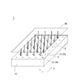
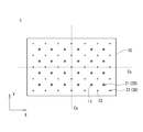
- FIG. 1 is an external view of a substrate holding device according to an embodiment of the present invention. It is the top view which looked at the substrate holding device concerning the embodiment of the present invention from the upper part.
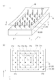
- FIG. 3A is an external view when the support member is pulled down when the first embodiment is applied
- FIG. 3B is a support member when the control method according to the first embodiment is applied. It is the schematic (plan view seen from the top) for demonstrating the structure (assignment) of a group and an adsorption
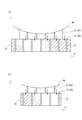
- 4A is a schematic view of a cross section taken along the line AA in FIG. 3A (cross section cut along the center line Cy)
- FIG. 4B is a cross section taken along the line BB in FIG.
- FIG. 5A is an external view when the support member is pulled down when the second embodiment is applied
- FIG. 5B is a support member when the control method according to the second embodiment is applied. It is the schematic (plan view seen from the top) for demonstrating the structure (assignment) of a group and an adsorption
- 6A is a schematic view of a cross section taken along the line CC in FIG. 5A (cross section taken along the center line Cy)
- FIG. 6B is a cross section taken along the line DD in FIG.
- 1 is a schematic view of an exposure apparatus according to an embodiment of the present invention. It is the schematic of the conventional board
- the substrate holding apparatus 1 includes a base member 10, support means 20 provided on the base member 10, suction means 30 provided on the base member 10, and the support means 20 and suction means 30. And control means for controlling.
- the base member 10 is a plate-like member on which the substrate 90 is finally placed. In the exposure apparatus 2 to be described later, a stage for exposing the substrate 90 is provided.
- the base member 10 is formed with a plurality of support member accommodation holes 11 in which the support members 21 are accommodated, and a plurality of suction holes 12 serving as suction elements 31 constituting the suction means 30.
- the support means 20 is an aggregate of a plurality of support members 21 (pins) accommodated in support member accommodation holes 11 formed in the base member 10.
- the support member 21 is provided so as to be able to protrude and retract above the base member 10 from the accommodation hole.
- the support member 21 is provided so as to be movable back and forth from a state where it is completely accommodated inside the support member accommodation hole 11 to a state where it protrudes a predetermined length from the upper surface of the base member 10 by an actuator (not shown). ing.
- support members 21 are arranged at equal intervals.
- the support member 21 is symmetrical with respect to a center line Cx that bisects the base member 10 in the X direction and a center line Cy that bisects the base member 10 in the Y direction. It is arranged to become.
- the interval between the support members 21 is set to a size that allows the arm of the robot carrying the substrate 90 to enter between the support members 21.
- the suction means 30 is configured to suck air from a plurality of suction holes 12 formed in the base member 10 and hold the substrate 90 on the base member 10. That is, suction means (not shown) is provided below the base member 10, and the suction means sucks air from each of the suction holes 12.
- the suction means 30 includes a plurality of suction elements 31 including the suction holes 12 and the suction means.
- adsorbing elements 31 are arranged at equal intervals.
- the adsorbing element 31 is symmetrical with respect to the center line Cx that bisects the base member 10 in the X direction and the center line Cy that bisects the base member 10 in the Y direction. It is arranged to become.
- Each support member 21 is equidistant from the four adsorbing elements 31 arranged around the support member 21.
- the supporting member group arranged in the X direction is positioned between the adsorbing element groups arranged linearly in the X direction
- the supporting member group arranged in the Y direction is positioned between the adsorbing element groups arranged in the Y direction.
- the control means controls the actuator that operates each support member 21 that constitutes the support means 20 and the suction means that operates each adsorption element 31 that constitutes the adsorption means 30.
- the control means can operate each of the plurality of support members 21 independently, and can also operate each of the plurality of adsorption elements 31 independently.
- the support means 20 and the suction means 30 operate as follows. First, a state in which all of the plurality of support members 21 protrude evenly from the upper surface of the base member 10 (a state in which each support member 21 is positioned at the forward end) is assumed. Thereafter, the substrate 90 is transported by the robot, and the substrate 90 is placed on the plurality of support members 21 protruding from the upper surface of the base member 10.
- control means lowers the support member 21 in a predetermined order and operates the suction element 31 in the predetermined order to hold the substrate 90 on the base member 10.
- Preferred examples of the predetermined order include the following first and second embodiments.
- the control means sequentially pulls down (with a time difference) from one or a plurality of support members 21 close to the center of the substrate 90 (base member 10).
- the member 21 the first support member group 21a, the second support member group 21b, and the third support member group 21c shown in FIG. Accordingly, the substrate 90 is lowered in a state of being bent in a substantially mountain shape with the center as the apex, and the center portion first contacts the base member 10. That is, the substrate 90 descends so as to contact the base member 10 in order from the portion near the center.
- the control means operates in order according to the substrate 90 descending from the substantially central portion as described above. That is, the suction means 30 starts the suction operation in order from one or a plurality of support members 21 close to the center of the substrate 90 (base member 10).
- the first adsorption element group 31a one adsorption element 31 in this embodiment
- the second adsorption element group 31b the third adsorption element group 31c
- a sensor is provided in the vicinity of each adsorption element 31 (or one of each adsorption element group), and the adsorption element 31 (covered by the substrate 90 descending from a substantially central portion) ( There is a method of operating in order from the adsorption element group).
- the first adsorption element group 31 a one adsorption element 31 located in the center of the base member 10 is covered with the substrate 90, One adsorption element group 31a operates. As a result, the central portion of the substrate 90 is attracted to the base member 10.
- the second adsorption element group 31b is covered with the substrate 90, and the second adsorption element group 31b operates.
- the third attachment element group is covered with the substrate 90, and the third adsorption element group 31c operates.
- the fourth attachment element group is covered with the substrate 90, and the fourth adsorption element group 31d operates. In this way, the operation is performed in order from the adsorption element group close to the center of the substrate 90 covered with the substrate 90, and the holding of the substrate 90 is completed when the operation of the fourth adsorption element group 31d located on the outermost side is completed.
- the suction elements 31 covered by the substrate 90 are operated in order. That is, since the suction is performed on the base member 10 sequentially from the portion where the suction becomes possible, the suction operation is smoothly performed.
- adsorption element group is set to operate in advance in association with the operation of the support member 21 (support member group).
- a certain adsorbing element group may be configured to operate when a lowering operation of a certain support member group is started or completed.
- the adsorption element group can be operated as follows. First, the control means lowers the first support member group 21a, and then lowers the second support member group 21b and the third support member group 21c in this order. Then, when the completion of the pulling-down operation of the first support member group 21a is detected, it is located inside the region surrounded by the first support member group 21a (closer to the center of the substrate 90 than the first support member group 21a). The first adsorption element group 31a is operated. After that, when the completion of the lowering operation of the second support member group 21b is detected, it is located inside the region surrounded by the second support member group 21b (closer to the center of the substrate 90 than the second support member group 21b).
- the second adsorption element group 31b is operated. After that, when the completion of the lowering operation of the third support member group 21c is detected, it is located inside the region surrounded by the third support member group 21c (closer to the center of the substrate 90 than the third support member group 21c). ) Operate the third adsorption element group 31c. Finally, when a predetermined time (several seconds) has passed since the completion of the lowering operation of the third support member group 21c was detected, the third support member group 21c is positioned outside the region surrounded by the third support member group 21c (third support member). The fourth adsorption element group 31d (which is farther from the center of the substrate 90 than the group 21c) is operated. When the operation of the fourth adsorption element group 31d is completed, the holding of the substrate 90 is completed.
- the adsorption element group closer to the center of the substrate 90 is sequentially operated.
- the base member 10 is sequentially attracted to the base member 10 from the inner region of the lowered support member group in the substrate 90, the attracting operation is performed smoothly.
- the method for controlling the timing for operating the adsorption element group a method for detecting and controlling that the adsorption element group is covered with the substrate 90 (first control example), and A method of controlling in association with the operation timing of the support member 21 (second control example) is mentioned.
- the above control method is an example, and can be appropriately changed according to the size of the substrate 90 and the arrangement of the support member 21 and the adsorption element 31.
- the control means pulls down the support member 21 sequentially (with a time difference) from a plurality of support members 21 close to one central line that bisects the substrate 90 (base member 10) in the plane direction (with a time difference) (
- the speed which pulls down the supporting member 21 is the same about all the supporting members 21).
- one center line is a center line Cx that bisects the substrate 90 in the X direction
- Pull down in order of the support member group 21c Therefore, the substrate 90 gradually descends from the portion close to the center line Cx, and the portion along the center line Cx first contacts the base member 10. That is, the substrate 90 descends in order from the portion close to the center line Cx so as to contact the base member 10.
- the substrate 90 bends and descends in a substantially mountain shape with the center of the substrate 90 as a vertex, whereas in the second embodiment, the portion along the center line Cx is a top line. The difference is that the substrate 90 is bent in a mountain shape and descends.
- the control means operates in order according to the substrate 90 descending from the portion along the center line Cx. That is, the suction means 30 starts the suction operation in order from one or a plurality of support members 21 close to the center line Cx of the substrate 90 (base member 10). Specifically, the first adsorption element group 31a, the second adsorption element group 31b, the third adsorption element group 31c, and the fourth adsorption element group 31d shown in FIG.
- the same method as in the first embodiment can be adopted. That is, the first control example (method for detecting and controlling that the adsorption element group is covered with the substrate 90) and the second control example (control in association with the operation timing of the support member 21) described in the first embodiment. Any of (Method) can be used.
- the support means 20 and the suction means 30 operate as follows.
- the first adsorption element group 31a located at the center of the base member 10 is covered with the substrate 90, and the first adsorption element group 31a operates.
- the central portion of the substrate 90 is attracted to the base member 10.
- the second adsorption element group 31b is covered with the substrate 90, and the second adsorption element group 31b operates.
- the third attachment element group is covered with the substrate 90, and the third adsorption element group 31c operates.
- the fourth attachment element group is covered with the substrate 90, and the fourth adsorption element group 31d operates.
- the operation is performed in order from the adsorption element group close to the center of the substrate 90 covered with the substrate 90, and the holding of the substrate 90 is completed when the operation of the fourth adsorption element group 31d located on the outermost side is completed.
- the suction elements 31 covered by the substrate 90 are operated in order. That is, since the suction is performed on the base member 10 sequentially from the portion where the suction becomes possible, the suction operation is smoothly performed.
- the adsorption element group can be operated as follows. First, the control means lowers the first support member group 21a, and then lowers the second support member group 21b and the third support member group 21c in this order. When the completion of the lowering operation of the first support member group 21a is detected, the first adsorption element group 31a closer to the center line Cx than the first support member group 21a is operated. Thereafter, when the completion of the lowering operation of the second support member group 21b is detected, the second adsorption element group 31b closer to the center line Cx than the second support member group 21b is operated.
- the adsorption element group closer to the center line Cx is sequentially operated. That is, since the base member 10 is sequentially attracted to the base member 10 from a region closer to the center line Cx than the lowered support member group in the substrate 90, the attracting operation is performed smoothly.
- the substrate holding device 1 adopting the first embodiment lowers the substrate 90 by lowering the support member 21 in order from one or more support members 21 close to the center of the substrate 90 (in order from the first support member group 21a), Since the suction element 31 is configured to perform the suction operation in order from one or a plurality of suction elements 31 close to the center of the substrate 90 (in order from the first suction element group 31a), the descending substrate 90 starts from the portion close to the center. 10, and is adsorbed by the adsorbing element 31. Therefore, it is possible to prevent or suppress the occurrence of air accumulation between the substrate 90 and the base member 10. That is, it is possible to prevent or suppress the occurrence of waviness in the substrate 90 held on the base member 10 or the displacement of the substrate 90.
- the substrate holding apparatus 1 pulls down the support member 21 in order from one or a plurality of support members 21 close to one central line that bisects the substrate 90 (in order from the first support member group 21a).
- the substrate 90 is lowered, and the suction element 31 is suctioned in order from one or a plurality of suction elements 31 close to the center line (in order from the first suction element group 31a).
- the base member 10 is brought into contact with the adsorbing element 31 from a portion close to the center line. Therefore, it is possible to prevent or suppress the occurrence of air accumulation between the substrate 90 and the base member 10. That is, it is possible to prevent or suppress the occurrence of waviness in the substrate 90 held on the base member 10 or the displacement of the substrate 90.
- the base member 10 is sequentially suctioned from the portion of the substrate 90 that is in contact with the base member 10 that descends. Therefore, by adopting this first control example, the effect of preventing or suppressing the occurrence of air accumulation between the substrate 90 and the base member 10 is further enhanced. Further, the holding operation of the substrate 90 is performed smoothly.
- a group of support members 21 that are operated simultaneously and a group of adsorption elements that are operated simultaneously are associated in advance, and the adsorption is performed according to the progress of the lowering operation of the support member 21 (the degree of lowering of the substrate 90).
- the element 31 is operated. Specifically, after the lowering operation of a certain support member group is completed, the adsorption element group closer to the center (first embodiment) or the center line Cx (second embodiment) of the substrate 90 is operated. . Therefore, the effect of preventing or suppressing the occurrence of air accumulation between the substrate 90 and the base member 10 is further enhanced. Further, the holding operation of the substrate 90 is performed smoothly.
- the apparatus structure becomes simple.
- the exposure apparatus 2 includes the substrate holding apparatus 1, a mask holding means 40 for holding an exposure mask 91 above the base member 10 (stage) of the substrate holding apparatus 1, and the mask holding. And illumination means 50 provided above the means 40.
- the mask holding means 40 is provided on the side of the base member 10 and holds the exposure mask 91. As shown in the figure, the mask holding means 40 is configured to hold an exposure mask 91 so as to separate the illumination means 50 and the substrate 90 that is an object to be irradiated. By this mask holding means 40, the exposure mask 91 is held in parallel with the substrate 90.
- the illumination means 50 is provided above the exposure mask 91 held by the mask holding means 40.
- the illuminating means 50 is composed of, for example, a plurality of ultraviolet lamps as light sources.
- the substrate 90 which is the object to be irradiated, is held at a predetermined position on the base member 10 of the substrate holding apparatus 1 by the above-described procedure. Since the exposure mask 91 is positioned at a predetermined position by the mask holding means 40, the relative positional relationship between the base member 10 and the exposure mask 91 is constant. Therefore, the relative positional relationship between the substrate 90 positioned at a predetermined position of the base member 10 and the exposure mask 91 is also constant.
- the exposure apparatus 2 As described above, when the substrate holding device 1 is used, the undulation of the substrate 90 held on the base member 10 and the displacement of the substrate 90 are prevented or suppressed. Therefore, according to the exposure apparatus 2 according to the present embodiment, exposure pattern shift and focus shift can be prevented or suppressed.
- the number of support members 21 provided in the support means 20 and the number of adsorption elements 31 provided in the adsorption means 30 in the above embodiment are merely examples, and can be appropriately changed.
Landscapes
- Physics & Mathematics (AREA)
- General Physics & Mathematics (AREA)
- Exposure And Positioning Against Photoresist Photosensitive Materials (AREA)
- Container, Conveyance, Adherence, Positioning, Of Wafer (AREA)
Abstract
ベース部材上に保持される基板にうねりが発生したり、基板が位置ずれしたりすることを防止または抑制する基板保持装置および露光装置を提供すること。ベース部材(10)と、このベース部材(10)の上面から進退動自在に設けられた複数の支持部材(21)を動作させる支持手段(20)と、ベース部材(10)の上面に形成された複数の吸着要素(31)を動作させる吸着手段(30)と、ベース部材(10)の上面から複数の支持部材(21)を均等に突出させ、この均等に突出した複数の支持部材(21)の上に可撓性のある基板(90)が支持された状態から、基板(90)の中央に近い一または複数の支持部材(21)から順に支持部材(21)を引き下げるように支持手段(20)を制御するとともに、基板(90)の中央に近い一または複数の吸着要素(31)から順に吸着要素(31)を吸着動作させるように吸着手段(30)を制御し、基板(90)を前記ベース部材(10)上に保持させる制御手段と、を備える。
Description
本発明は、表示パネルを構成する基板(特に大型の基板)を支持する基板保持装置およびこの基板保持装置を用いた露光装置に関する。
液晶表示装置などの表示装置に用いられる大型の基板を、露光装置などのステージ(ベース部材)上に載置させるための装置(基板をステージに保持させる装置)が知られている(例えば特許文献1参照)。
図8は、この種の基板保持装置の従来構造を示したものである。基板保持装置100は、ベース部材102と、そのベース部材102の上面から進退動自在に設けられた複数の支持部材104と、ベース部材102に設けられた複数の吸着要素106と、を備える。ロボットなどによって搬送された基板90は、ベース部材102から所定長さ突出した支持部材104の先端に載置される。その後、支持部材104を一斉に引き下げ(ベース部材100内部に収容させ)、吸着要素106によってベース部材102上に基板90を吸着保持する。
しかし、上記従来の基板保持装置には次のような問題がある。支持部材104に支持された基板90は、支持部材104に接触していない箇所が基板90自身の重みにより重力方向に撓んでしまう。すなわち、図8(a)に示されるように基板90がうねる。したがって、そのまま基板90を引き下げると、図8(b)に示すように吸着要素106のいくつかがうねった基板90によって塞がれた状態となり、基板90とベース部材102との間に空気が溜まってしまい、基板90がうねった状態でそのままベース部材102上に保持されてしまう。このような基板90のうねりは、例えば基板保持装置100が露光装置に用いられた場合には、露光のパターンずれやピントずれを引き起こす。また、基板90とベース部材102との間に溜まった空気により、基板90が平面方向に流れてしまう(位置ずれしてしまう)といった問題も発生する。
上記実情に鑑み、本発明が解決しようとする課題は、ベース部材上に保持される基板にうねりが発生したり、基板が位置ずれしたりすることを防止または抑制する基板保持装置および露光装置を提供することにある。
上記課題を解決するために本発明にかかる基板保持装置は、ベース部材と、このベース部材の上面から進退動自在に設けられた複数の支持部材を有する支持手段と、前記ベース部材の上面に形成された複数の吸着要素を有する吸着手段と、前記ベース部材の上面から前記複数の支持部材を均等に突出させ、この均等に突出した複数の支持部材の上に可撓性のある基板が支持された状態から、前記基板の中央に近い一または複数の支持部材から順に前記支持部材を引き下げるように前記支持手段を制御するとともに、前記基板の中央に近い一または複数の吸着要素から順に前記吸着要素を吸着動作させるように前記吸着手段を制御し、前記基板を前記ベース部材上に保持させる制御手段と、を備えることを要旨とするものである。
上記課題を解決するために別の本発明にかかる基板保持装置は、ベース部材と、このベース部材の上面から進退動自在に設けられた複数の支持部材を有する支持手段と、前記ベース部材の上面に形成された複数の吸着要素を有する吸着手段と、前記ベース部材の上面から前記複数の支持部材を均等に突出させ、この均等に突出した複数の支持部材の上に可撓性のある基板が支持された状態から、前記基板を平面方向に二等分する一の中央線に近い複数の支持部材から順に前記支持部材を引き下げるように前記支持手段を制御するとともに、前記複数の吸着要素のうち前記基板を平面方向に二等分する一の中央線に近い複数の吸着要素から順に前記吸着要素を吸着動作させるように前記吸着手段を制御し、前記基板を前記ベース部材上に保持させる制御手段と、を備えることを要旨とするものである。
また、上記構成において、前記制御手段は、前記複数の吸着要素のうち前記基板によって覆われた吸着要素から順に吸着動作させるように前記吸着手段を制御する構成であればよい。
また、前記複数の支持部材のうち同時に引き下げ動作させる一または複数の一群の支持部材、および、前記複数の吸着要素のうち同時に吸着動作させる一または複数の一群の吸着要素が設定されており、前記制御手段は、ある一群の支持部材の引き下げ動作の経過に応じて、ある一群の吸着要素による吸着動作を開始させるように構成するとよい。
また、前記吸着手段が有する前記複数の吸着要素は、前記ベース部材に形成された複数の開口のそれぞれから空気を吸引する構成であればよい。
一方、上記課題を解決するために本発明にかかる露光装置は、上記いずれかに記載される基板保持装置と、この基板保持装置の前記ベース部材上に保持された基板の上部で、所定のパターンが形成されたマスクを保持するマスク保持手段と、このマスク保持手段に保持されたマスクをその上部から照らす照明手段と、を備えることを要旨とする。
本発明にかかる基板保持装置は、基板の中央に近い一または複数の支持部材から順に支持部材を引き下げて基板を下降させ、基板の中央に近い一または複数の吸着要素から順に吸着要素を吸着動作させる構成であるため、下降する基板は、その中央に近い部分からベース部材に接触し、吸着要素に吸着されていく。したがって、基板とベース部材との間に空気溜まりが発生することを防止または抑制することができる。すなわち、ベース部材上に保持される基板にうねりが発生したり、基板が位置ずれしたりすることを防止または抑制することができる。
また、別の本発明にかかる基板保持装置は、基板を二等分する一の中央線に近い一または複数の支持部材から順に支持部材を引き下げて基板を下降させ、当該中央線に近い一または複数の吸着要素から順に吸着要素を吸着動作させる構成であるため、下降する基板は、当該中央線に近い部分からベース部材に接触し、吸着要素に吸着されていく。したがって、基板とベース部材との間に空気溜まりが発生することを防止または抑制することができる。すなわち、ベース部材上に保持される基板にうねりが発生したり、基板が位置ずれしたりすることを防止または抑制することができる。
また、上記構成において、基板によって覆われた吸着要素から順に吸着動作させるようにすれば、下降する基板のベース部材に接触した部分から順にベース部材に吸着されていくため、基板とベース部材との間に空気溜まりが発生することを防止または抑制する効果がさらに高まる。また、基板の保持動作がスムーズになされる。
一方、上記構成において、同時に動作させる一群の支持部材と、同時に動作させる一群の吸着要素を予め関連づけておけば、支持部材の引き下げ動作の経過(基板の下降の程度)に応じて吸着要素を動作させることができるため、基板とベース部材との間に空気溜まりが発生することを防止または抑制する効果がさらに高まる。また、基板の保持動作がスムーズになされる。
また、吸着要素をベース部材に形成された開口から空気を吸引する構成とすれば、装置構成を簡易なものとすることができる。
一方、上記本発明にかかる露光装置によれば、ベース部材上に保持された基板のうねりや位置ずれが防止または抑制されるから、露光のパターンずれやピントずれを防止または抑制することができる。
以下、本発明の実施形態について、図面を参照して詳細に説明する。なお、特に明示した場合を除き、以下の説明における上下方向とは図4、図6、図7における上下方向をいう。
本実施形態にかかる基板保持装置1は、ベース部材10と、このベース部材10に設けられた支持手段20と、同じくベース部材10に設けられた吸着手段30と、これら支持手段20および吸着手段30を制御する制御手段と、を備える。
ベース部材10は、最終的に基板90が載置される板状の部材である。後述する露光装置2では、基板90を露光処理するためのステージとなる。ベース部材10には、支持部材21が収容される複数の支持部材収容穴11と、吸着手段30を構成する吸着要素31となる複数の吸着穴12が形成されている。
支持手段20は、ベース部材10に形成された支持部材収容穴11に収容された複数の支持部材21(ピン)の集合体である。この支持部材21は、収容穴からベース部材10の上側に出没自在に設けられている。具体的には、支持部材21は、図示されないアクチュエータにより、支持部材収容穴11の内側に完全に収容された状態から、ベース部材10の上面から所定長さ突出した状態まで進退動自在に設けられている。
本実施形態では、図2に示すように6(X方向)×4(Y方向)=24個の支持部材21が等間隔に配置されている。ベース部材10の平面方向で見ると、支持部材21は、ベース部材10をX方向に二等分する中央線Cxおよびベース部材10をY方向に二等分する中央線Cyを対称軸として線対称となるように配置されている。なお、支持部材21の間隔は、基板90を運搬するロボットのアームが支持部材21間に入り込むことが可能な大きさに設定されている。
吸着手段30は、ベース部材10に形成された複数の吸着穴12から空気を吸引し、基板90をベース部材10に保持するための構成である。すなわち、ベース部材10の下方には図示されない吸引手段が設けられており、吸引手段は吸着穴12のそれぞれから空気を吸引する。このように、吸着手段30は、各吸着穴12および吸引手段から構成される複数の吸着要素31を備える。
本実施形態では、図2に示すように7(X方向)×5(Y方向)=35個の吸着要素31が等間隔に配置されている。ベース部材10の平面方向で見ると、吸着要素31は、ベース部材10をX方向に二等分する中央線Cxおよびベース部材10をY方向に二等分する中央線Cyを対称軸として線対称となるように配置されている。各支持部材21は、その周囲に配置された四つの吸着要素31から等距離にある。すなわち、X方向に直線状に並ぶ吸着要素群の同士の間にX方向に並ぶ支持部材群が位置し、Y方向に並ぶ吸着要素群同士の間にY方向に並ぶ支持部材群が位置する。
制御手段は、上記支持手段20を構成する各支持部材21を動作させるアクチュエータ、および、上記吸着手段30を構成する各吸着要素31を動作させる吸引手段を制御する。制御手段は、複数の支持部材21のそれぞれを独立して動作させることが可能であり、複数の吸着要素31のそれぞれを独立して動作させることも可能である。
かかる制御手段によって支持手段20および吸着手段30は次のように動作する。まず、ベース部材10の上面から複数の支持部材21の全てが均等に突出した状態(各支持部材21が前進端に位置する状態)とする。この後、ロボットによって基板90が運搬され、ベース部材10の上面から突出した複数の支持部材21の上に基板90が載置される。
この後、制御手段は支持部材21を所定の順で引き下げ、所定の順で吸着要素31を動作させることによって基板90をベース部材10に保持させる。その所定の順の好適な例としては、以下の第一実施例および第二実施例が挙げられる。
まず、第一実施例について説明する。第一実施例では、制御手段は、基板90(ベース部材10)の中央に近い一または複数の支持部材21から順に(時間差をつけて)引き下げる(なお、支持部材21を引き下げる速度は全ての支持部材21について同じである。)。具体的には、図3(b)に示す第一支持部材群21a、第二支持部材群21b、第三支持部材群21cの順に引き下げる。したがって、基板90はその中央を頂点とする略山状に撓んだ状態で下降し、中央部分が最初にベース部材10に接触する。つまり、基板90はその中央に近い部分から順にベース部材10に接触するように下降する。
一方、制御手段は、このように略中央部分から下降していく基板90に合わせて順に動作する。つまり、吸着手段30は、基板90(ベース部材10)の中央に近い一または複数の支持部材21から順に吸着動作を開始することになる。具体的には、図3(b)に示す第一吸着要素群31a(本実施形態では一の吸着要素31)、第二吸着要素群31b、第三吸着要素群31c、第四吸着要素群31dの順に動作する。
これら吸着要素群を動作させるタイミングを制御する方法としては、様々な例が考えられる。第一制御例としては、各吸着要素31(あるいは各吸着要素群のうちの一つ)の近傍にセンサを設けておき、略中央部分から下降していく基板90に覆われた吸着要素31(吸着要素群)から順に動作させる方法が挙げられる。本実施形態では、基板90の中央部分がベース部材10に接触すると、ベース部材10の中央に位置する第一吸着要素群31a(一の吸着要素31)が基板90に覆われた状態となり、第一吸着要素群31aが動作する。これにより基板90の中央部分がベース部材10に吸着される。その後、第二吸着要素群31bが基板90に覆われた状態となり、第二吸着要素群31bが動作する。さらにその後、第三着要素群が基板90に覆われた状態となり、第三吸着要素群31cが動作する。最後に第四着要素群が基板90に覆われた状態となり、第四吸着要素群31dが動作する。このように、基板90に覆われた基板90の中央に近い吸着要素群から順に動作し、最も外側に位置する第四吸着要素群31dの動作が完了したことをもって基板90の保持が完了する。
このように、第一制御例は、基板90によって覆われた吸着要素31から順に動作させていくものである。つまり、吸着可能となった部分から順次ベース部材10に吸着させていく方法であるため、吸着動作がスムーズになされる。
また、吸着要素群を動作させるタイミングを制御する第二制御例としては、予め支持部材21(支持部材群)の動作に関連づけて吸着要素群が動作するように設定しておく方法である。具体的には、ある支持部材群の引き下げ動作が開始または完了したことを契機として、ある吸着要素群を動作させるように構成すればよい。
本実施形態では、例えば次のように吸着要素群を動作させることができる。まず、制御手段は、第一支持部材群21aを引き下げ、その後、第二支持部材群21b、第三支持部材群21cの順に引き下げる。そして、第一支持部材群21aの引き下げ動作の完了を検出したことをもって、第一支持部材群21aで囲まれる領域の内側に位置する(第一支持部材群21aよりも基板90の中央に近い)第一吸着要素群31aを動作させる。その後、第二支持部材群21bの引き下げ動作の完了を検出したことをもって、第二支持部材群21bで囲まれる領域の内側に位置する(第二支持部材群21bよりも基板90の中央に近い)第二吸着要素群31bを動作させる。さらにその後、第三支持部材群21cの引き下げ動作の完了を検出したことをもって、第三支持部材群21cで囲まれる領域の内側に位置する(第三支持部材群21cよりも基板90の中央に近い)第三吸着要素群31cを動作させる。そして最後に、第三支持部材群21cの引き下げ動作の完了を検出してから所定時間(数秒)経過したことをもって、第三支持部材群21cで囲まれる領域の外側に位置する(第三支持部材群21cよりも基板90の中央から遠い)第四吸着要素群31dを動作させる。この第四吸着要素群31dの動作が完了により基板90の保持が完了する。
このように、第二制御例は、ある支持部材群の引き下げ動作が完了した後に、それより基板90の中央に近い吸着要素群を順次動作させていくものである。つまり、基板90における引き下げられた支持部材群の内側の領域から順次ベース部材10に吸着させていく方法であるため、吸着動作がスムーズになされる。
以上説明したように、吸着要素群を動作させるタイミングを制御する方法の好適な例としては、吸着要素群が基板90に覆われたことを検出して制御する方法(第一制御例)、および、支持部材21の動作タイミングに関連づけて制御する方法(第二制御例)が挙げられる。いずれの方法においても、上記制御方法は一例であり、基板90の大きさや支持部材21および吸着要素31の配置に応じて適宜変更可能である。
次に、第二実施例について説明する。第二実施例では、制御手段は、基板90(ベース部材10)を平面方向に二等分する一の中央線に近い複数の支持部材21から順に(時間差をつけて)支持部材21を引き下げる(なお、支持部材21を引き下げる速度は全ての支持部材21について同じである)。具体的には、一の中央線を基板90をX方向に二等分する中央線Cxとする場合、図5(b)に示す第一支持部材群21a、第二支持部材群21b、第三支持部材群21cの順に引き下げる。したがって、基板90は、中央線Cxに近い部分から徐々に下降し、中央線Cxに沿う部分が最初にベース部材10に接触する。つまり、基板90は、中央線Cxに近い部分から順にベース部材10に接触するように下降する。
すなわち、第一実施例は、基板90の中央を頂点とする略山状に基板90が撓んで下降するのに対し、第二実施例は、中央線Cxに沿った部分を頂線とする略山状に基板90が撓んで下降する点で異なる。
一方、制御手段は、このように中央線Cxに沿った部分から下降していく基板90に合わせて順に動作する。つまり、吸着手段30は、基板90(ベース部材10)の中央線Cxに近い一または複数の支持部材21から順に吸着動作を開始することになる。具体的には、図5(b)に示す第一吸着要素群31a、第二吸着要素群31b、第三吸着要素群31c、第四吸着要素群31dの順に動作する。
これら吸着要素群を動作させるタイミングを制御する方法は、例えば上記第一実施例と同様の方法を採用することができる。すなわち、第一実施例において説明した第一制御例(吸着要素群が基板90に覆われたことを検出して制御する方法)および第二制御例(支持部材21の動作タイミングに関連づけて制御する方法)のいずれを用いることもできる。
第一制御例を採用した場合は、支持手段20および吸着手段30は次のように動作する。基板90の中央線Cxに沿う部分がベース部材10に接触すると、ベース部材10の中央に位置する第一吸着要素群31aが基板90に覆われた状態となり、第一吸着要素群31aが動作する。これにより基板90の中央部分がベース部材10に吸着される。その後、第二吸着要素群31bが基板90に覆われた状態となり、第二吸着要素群31bが動作する。さらにその後、第三着要素群が基板90に覆われた状態となり、第三吸着要素群31cが動作する。最後に第四着要素群が基板90に覆われた状態となり、第四吸着要素群31dが動作する。このように、基板90に覆われた基板90の中央に近い吸着要素群から順に動作し、最も外側に位置する第四吸着要素群31dの動作が完了したことをもって基板90の保持が完了する。
このように、第一制御例は、基板90によって覆われた吸着要素31から順に動作させていくものである。つまり、吸着可能となった部分から順次ベース部材10に吸着させていく方法であるため、吸着動作がスムーズになされる。
一方、第二制御例を採用した場合は、例えば次のように吸着要素群を動作させることができる。まず、制御手段は、制御手段は、第一支持部材群21aを引き下げ、その後、第二支持部材群21b、第三支持部材群21cの順に引き下げる。そして、第一支持部材群21aの引き下げ動作の完了を検出したことをもって、第一支持部材群21aよりも中央線Cxに近い第一吸着要素群31aを動作させる。その後、第二支持部材群21bの引き下げ動作の完了を検出したことをもって、第二支持部材群21bよりも中央線Cxに近い第二吸着要素群31bを動作させる。さらにその後、第三支持部材群21cの引き下げ動作の完了を検出したことをもって、第三支持部材群21cよりも中央線Cxに近い第三吸着要素群31cを動作させる。そして最後に、第三支持部材群21cの引き下げ動作の完了を検出してから所定時間(数秒)経過したことをもって、第三支持部材群21cよりも中央線Cxから遠い第四吸着要素群31dを動作させる。この第四吸着要素群31dの動作が完了により基板90の保持が完了する。
このように、第二制御例は、ある支持部材群の引き下げ動作が完了した後に、それより中央線Cxに近い吸着要素群を順次動作させていくものである。つまり、基板90における引き下げられた支持部材群よりも中央線Cxに近い領域から順次ベース部材10に吸着させていく方法であるため、吸着動作がスムーズになされる。
以上説明した本実施形態にかかる基板保持装置1によれば、次のような作用効果が奏される。
第一実施例を採用した基板保持装置1は、基板90の中央に近い一または複数の支持部材21から順に(第一支持部材群21aから順に)支持部材21を引き下げて基板90を下降させ、基板90の中央に近い一または複数の吸着要素31から順に(第一吸着要素群31aから順に)吸着要素31を吸着動作させる構成であるため、下降する基板90はその中央に近い部分からベース部材10に接触し、吸着要素31に吸着されていく。したがって、基板90とベース部材10との間に空気溜まりが発生することを防止または抑制することができる。すなわち、ベース部材10上に保持される基板90にうねりが発生したり、基板90が位置ずれしたりすることを防止または抑制することができる。
第二実施例を採用した基板保持装置1は、基板90を二等分する一の中央線に近い一または複数の支持部材21から順に(第一支持部材群21aから順に)支持部材21を引き下げて基板90を下降させ、当該中央線に近い一または複数の吸着要素31から順に(第一吸着要素群31aから順に)吸着要素31を吸着動作させる構成であるため、下降する基板90は、当該中央線に近い部分からベース部材10に接触し、吸着要素31に吸着されていく。したがって、基板90とベース部材10との間に空気溜まりが発生することを防止または抑制することができる。すなわち、ベース部材10上に保持される基板90にうねりが発生したり、基板90が位置ずれしたりすることを防止または抑制することができる。
また、第一制御例は、基板90によって覆われた吸着要素31から順に吸着動作させるものであるため、下降する基板90のベース部材10に接触した部分から順にベース部材10に吸着されていく。したがって、かかる第一制御例を採用することにより、基板90とベース部材10との間に空気溜まりが発生することを防止または抑制する効果がさらに高まる。また、基板90の保持動作がスムーズになされる。
また、第二制御例は、同時に動作させる一群の支持部材21と、同時に動作させる一群の吸着要素を予め関連づけて、支持部材21の引き下げ動作の経過(基板90の下降の程度)に応じて吸着要素31を動作させるものである。具体的には、ある支持部材群の引き下げ動作が完了した後、それより基板90の中央(第一実施例)あるいは中央線Cx(第二実施例)に近い吸着要素群を動作させるものである。したがって、基板90とベース部材10との間に空気溜まりが発生することを防止または抑制する効果がさらに高まる。また、基板90の保持動作がスムーズになされる。
また、上記実施形態は、吸着要素31をベース部材10に形成された開口から空気を吸引する構成であるため、装置構成を簡易なものとなる。
次に、本発明の実施形態にかかる露光装置2について説明する。図7に示すように、露光装置2は、上記基板保持装置1と、この基板保持装置1のベース部材10(ステージ)より上側で露光用マスク91を保持するマスク保持手段40と、このマスク保持手段40より上側に設けられる照明手段50とを備える。
マスク保持手段40は、ベース部材10の側方に設けられ、露光用マスク91を保持する。図示されるように、マスク保持手段40は、照明手段50と被照射体である基板90とを隔てるように露光用マスク91を保持できるように構成されている。かかるマスク保持手段40により、露光用マスク91は基板90と平行に保持される。
照明手段50は、マスク保持手段40に保持された露光用マスク91よりも上側に設けられる。かかる照明手段50は、例えば光源としての複数の紫外線ランプなどから構成される。
被照射体である基板90は、上述した手順によって基板保持装置1のベース部材10に所定位置に保持される。露光用マスク91は、マスク保持手段40によって所定位置に位置決めされるから、ベース部材10と露光用マスク91の相対的位置関係は一定である。したがって、ベース部材10の所定位置に位置決めされる基板90と露光用マスク91の相対的位置関係も一定である。
上述したように、基板保持装置1を用いれば、ベース部材10上に保持される基板90のうねりや基板90の位置ずれが防止または抑制される。したがって、本実施形態にかかる露光装置2によれば、露光のパターンずれやピントずれを防止または抑制することができる。
以上、本発明の実施の形態について詳細に説明したが、本発明は上記実施の形態に何ら限定されるものではなく、本発明の要旨を逸脱しない範囲で種々の改変が可能である。
上記実施形態における支持手段20が備える支持部材21の数、および、吸着手段30が備える吸着要素31の数はあくまで例示であり、適宜変更可能である。
Claims (6)
- ベース部材と、
このベース部材の上面から進退動自在に設けられた複数の支持部材を有する支持手段と、
前記ベース部材の上面に形成された複数の吸着要素を有する吸着手段と、
前記ベース部材の上面から前記複数の支持部材を均等に突出させ、この均等に突出した複数の支持部材の上に可撓性のある基板が支持された状態から、前記基板の中央に近い一または複数の支持部材から順に前記支持部材を引き下げるように前記支持手段を制御するとともに、前記基板の中央に近い一または複数の吸着要素から順に前記吸着要素を吸着動作させるように前記吸着手段を制御し、前記基板を前記ベース部材上に保持させる制御手段と、
を備えることを特徴とする基板保持装置。 - ベース部材と、
このベース部材の上面から進退動自在に設けられた複数の支持部材を有する支持手段と、
前記ベース部材の上面に形成された複数の吸着要素を有する吸着手段と、
前記ベース部材の上面から前記複数の支持部材を均等に突出させ、この均等に突出した複数の支持部材の上に可撓性のある基板が支持された状態から、前記基板を平面方向に二等分する一の中央線に近い複数の支持部材から順に前記支持部材を引き下げるように前記支持手段を制御するとともに、前記複数の吸着要素のうち前記基板を平面方向に二等分する一の中央線に近い複数の吸着要素から順に前記吸着要素を吸着動作させるように前記吸着手段を制御し、前記基板を前記ベース部材上に保持させる制御手段と、
を備えることを特徴とする基板保持装置。 - 前記制御手段は、前記複数の吸着要素のうち前記基板によって覆われた吸着要素から順に吸着動作させるように前記吸着手段を制御することを特徴とする請求項1または請求項2に記載の基板保持装置。
- 前記複数の支持部材のうち同時に引き下げ動作させる一または複数の一群の支持部材、および、前記複数の吸着要素のうち同時に吸着動作させる一または複数の一群の吸着要素が設定されており、
前記制御手段は、ある一群の支持部材の引き下げ動作の経過に応じて、ある一群の吸着要素による吸着動作を開始させることを特徴とする請求項1または請求項2に記載の基板保持装置。 - 前記吸着手段が有する前記複数の吸着要素は、前記ベース部材に形成された複数の開口のそれぞれから空気を吸引する構成であることを特徴とする請求項1から請求項4のいずれか一項に記載の基板保持装置。
- 請求項1~5のいずれか一項に記載される基板保持装置と、
この基板保持装置の前記ベース部材上に保持された基板の上部で、所定のパターンが形成されたマスクを保持するマスク保持手段と、
このマスク保持手段に保持されたマスクをその上部から照らす照明手段と、
を備える露光装置。
Applications Claiming Priority (2)
| Application Number | Priority Date | Filing Date | Title |
|---|---|---|---|
| JP2011024649 | 2011-02-08 | ||
| JP2011-024649 | 2011-02-08 |
Publications (1)
| Publication Number | Publication Date |
|---|---|
| WO2012108263A1 true WO2012108263A1 (ja) | 2012-08-16 |
Family
ID=46638480
Family Applications (1)
| Application Number | Title | Priority Date | Filing Date |
|---|---|---|---|
| PCT/JP2012/051537 Ceased WO2012108263A1 (ja) | 2011-02-08 | 2012-01-25 | 基板保持装置および露光装置 |
Country Status (1)
| Country | Link |
|---|---|
| WO (1) | WO2012108263A1 (ja) |
Citations (4)
| Publication number | Priority date | Publication date | Assignee | Title |
|---|---|---|---|---|
| JP2005085881A (ja) * | 2003-09-05 | 2005-03-31 | Dainippon Screen Mfg Co Ltd | 基板処理装置および基板処理方法 |
| JP2006344675A (ja) * | 2005-06-07 | 2006-12-21 | Dainippon Printing Co Ltd | 基板の位置決め方法及び装置 |
| JP2008294100A (ja) * | 2007-05-23 | 2008-12-04 | Japan Steel Works Ltd:The | 基板保持装置 |
| JP2008311466A (ja) * | 2007-06-15 | 2008-12-25 | Dainippon Screen Mfg Co Ltd | 基板保持装置および基板処理装置 |
-
2012
- 2012-01-25 WO PCT/JP2012/051537 patent/WO2012108263A1/ja not_active Ceased
Patent Citations (4)
| Publication number | Priority date | Publication date | Assignee | Title |
|---|---|---|---|---|
| JP2005085881A (ja) * | 2003-09-05 | 2005-03-31 | Dainippon Screen Mfg Co Ltd | 基板処理装置および基板処理方法 |
| JP2006344675A (ja) * | 2005-06-07 | 2006-12-21 | Dainippon Printing Co Ltd | 基板の位置決め方法及び装置 |
| JP2008294100A (ja) * | 2007-05-23 | 2008-12-04 | Japan Steel Works Ltd:The | 基板保持装置 |
| JP2008311466A (ja) * | 2007-06-15 | 2008-12-25 | Dainippon Screen Mfg Co Ltd | 基板保持装置および基板処理装置 |
Similar Documents
| Publication | Publication Date | Title |
|---|---|---|
| CN101740349B (zh) | 芯片分离器 | |
| CN109385601B (zh) | 掩膜制造装置以及掩膜制造方法 | |
| JP4080401B2 (ja) | 基板処理装置および基板処理方法 | |
| JP2020141148A (ja) | 物体搬送装置、露光装置、フラットパネルディスプレイの製造方法、デバイス製造方法、物体搬送方法、及び露光方法 | |
| JP6708233B2 (ja) | 物体移動装置、露光装置、フラットパネルディスプレイの製造方法、及びデバイス製造方法 | |
| TW201838076A (zh) | 搬送裝置、搬送方法、曝光裝置、以及元件製造方法 | |
| JP2008235472A (ja) | 基板処理装置 | |
| TWI680528B (zh) | 晶圓取放裝置 | |
| WO2012108263A1 (ja) | 基板保持装置および露光装置 | |
| KR101329980B1 (ko) | 반데르발스 힘에 기초한 흡착력을 갖는 부재를 구비하는 복합형 척 | |
| JP2012237817A (ja) | 露光装置及び露光方法 | |
| JP5004786B2 (ja) | 露光装置の反転部 | |
| JP6036958B2 (ja) | 露光装置 | |
| JP5123766B2 (ja) | 露光装置 | |
| JP6015984B2 (ja) | 物体搬出方法、物体交換方法、物体保持装置、物体交換システム、露光装置、フラットパネルディスプレイの製造方法、及びデバイス製造方法 | |
| JP6631655B2 (ja) | 露光装置、フラットパネルディスプレイの製造方法及びデバイスの製造方法 | |
| JP2009229081A (ja) | ミクロ検査装置及びミクロ検査方法 | |
| JP2013130608A (ja) | 露光装置 | |
| JP2010091435A (ja) | 基板検査装置 | |
| JP2010176080A (ja) | プロキシミティ露光装置、及びプロキシミティ露光装置のチャック清掃方法 | |
| CN110520798A (zh) | 物体交换装置、物体处理装置、平板显示器的制造方法、元件制造方法、物体交换方法、以及物体处理方法 | |
| HK1205277B (en) | Object-swapping method, object-swapping system, exposure apparatus, method for manufacturing flat-panel display, and method for manufacturing device | |
| JP2015111732A (ja) | 脆性材料基板の搬送装置 |
Legal Events
| Date | Code | Title | Description |
|---|---|---|---|
| 121 | Ep: the epo has been informed by wipo that ep was designated in this application |
Ref document number: 12744983 Country of ref document: EP Kind code of ref document: A1 |
|
| NENP | Non-entry into the national phase |
Ref country code: DE |
|
| 122 | Ep: pct application non-entry in european phase |
Ref document number: 12744983 Country of ref document: EP Kind code of ref document: A1 |
|
| NENP | Non-entry into the national phase |
Ref country code: JP |