WO2012105364A1 - 角形密閉電池 - Google Patents
角形密閉電池 Download PDFInfo
- Publication number
- WO2012105364A1 WO2012105364A1 PCT/JP2012/051399 JP2012051399W WO2012105364A1 WO 2012105364 A1 WO2012105364 A1 WO 2012105364A1 JP 2012051399 W JP2012051399 W JP 2012051399W WO 2012105364 A1 WO2012105364 A1 WO 2012105364A1
- Authority
- WO
- WIPO (PCT)
- Prior art keywords
- sealing plate
- groove
- thin portion
- sealed battery
- battery
- Prior art date
- Legal status (The legal status is an assumption and is not a legal conclusion. Google has not performed a legal analysis and makes no representation as to the accuracy of the status listed.)
- Ceased
Links
Images


Classifications
-
- H—ELECTRICITY
- H01—ELECTRIC ELEMENTS
- H01M—PROCESSES OR MEANS, e.g. BATTERIES, FOR THE DIRECT CONVERSION OF CHEMICAL ENERGY INTO ELECTRICAL ENERGY
- H01M50/00—Constructional details or processes of manufacture of the non-active parts of electrochemical cells other than fuel cells, e.g. hybrid cells
- H01M50/10—Primary casings; Jackets or wrappings
- H01M50/102—Primary casings; Jackets or wrappings characterised by their shape or physical structure
- H01M50/103—Primary casings; Jackets or wrappings characterised by their shape or physical structure prismatic or rectangular
-
- H—ELECTRICITY
- H01—ELECTRIC ELEMENTS
- H01M—PROCESSES OR MEANS, e.g. BATTERIES, FOR THE DIRECT CONVERSION OF CHEMICAL ENERGY INTO ELECTRICAL ENERGY
- H01M50/00—Constructional details or processes of manufacture of the non-active parts of electrochemical cells other than fuel cells, e.g. hybrid cells
- H01M50/10—Primary casings; Jackets or wrappings
- H01M50/147—Lids or covers
- H01M50/148—Lids or covers characterised by their shape
- H01M50/15—Lids or covers characterised by their shape for prismatic or rectangular cells
-
- H—ELECTRICITY
- H01—ELECTRIC ELEMENTS
- H01M—PROCESSES OR MEANS, e.g. BATTERIES, FOR THE DIRECT CONVERSION OF CHEMICAL ENERGY INTO ELECTRICAL ENERGY
- H01M50/00—Constructional details or processes of manufacture of the non-active parts of electrochemical cells other than fuel cells, e.g. hybrid cells
- H01M50/30—Arrangements for facilitating escape of gases
- H01M50/342—Non-re-sealable arrangements
- H01M50/3425—Non-re-sealable arrangements in the form of rupturable membranes or weakened parts, e.g. pierced with the aid of a sharp member
-
- H—ELECTRICITY
- H01—ELECTRIC ELEMENTS
- H01M—PROCESSES OR MEANS, e.g. BATTERIES, FOR THE DIRECT CONVERSION OF CHEMICAL ENERGY INTO ELECTRICAL ENERGY
- H01M10/00—Secondary cells; Manufacture thereof
- H01M10/05—Accumulators with non-aqueous electrolyte
- H01M10/052—Li-accumulators
-
- Y—GENERAL TAGGING OF NEW TECHNOLOGICAL DEVELOPMENTS; GENERAL TAGGING OF CROSS-SECTIONAL TECHNOLOGIES SPANNING OVER SEVERAL SECTIONS OF THE IPC; TECHNICAL SUBJECTS COVERED BY FORMER USPC CROSS-REFERENCE ART COLLECTIONS [XRACs] AND DIGESTS
- Y02—TECHNOLOGIES OR APPLICATIONS FOR MITIGATION OR ADAPTATION AGAINST CLIMATE CHANGE
- Y02E—REDUCTION OF GREENHOUSE GAS [GHG] EMISSIONS, RELATED TO ENERGY GENERATION, TRANSMISSION OR DISTRIBUTION
- Y02E60/00—Enabling technologies; Technologies with a potential or indirect contribution to GHG emissions mitigation
- Y02E60/10—Energy storage using batteries
Definitions
- the present invention relates to a rectangular sealed battery, and in particular, when an increase in internal pressure due to gas generation occurs, the open area of a portion that operates as a safety valve formed on a sealing plate is increased to discharge gas inside the battery.
- the present invention relates to a prismatic sealed battery excellent in safety that has a reduced strength and is discharged in a short time.
- Non-aqueous electrolyte secondary typified by lithium-ion secondary battery with high energy density and high capacity as a driving power source for portable electronic devices such as mobile phones, portable personal computers, portable music players, etc. Batteries are widely used. Among these, nonaqueous electrolyte secondary batteries using graphite particles as the negative electrode active material are widely used because of their high safety and high capacity. In devices in which this type of non-aqueous electrolyte secondary battery is used, the space for accommodating the battery is often a square shape, so that a flat wound electrode body or a laminated electrode body is sealed in a rectangular outer can. Many square sealed batteries housed in a state are used.
- a nonaqueous electrolyte secondary battery when the non-aqueous electrolyte secondary battery is exposed to a high temperature or improper charging / discharging is performed, the electrolytic solution decomposes and generates gas due to an abnormal reaction between the electrode and the electrolytic solution.
- the pressure inside the battery hereinafter sometimes referred to as battery internal pressure
- the battery internal pressure increases. If the battery internal pressure rises excessively, the battery may burst. Therefore, a nonaqueous electrolyte secondary battery, whether cylindrical or rectangular, is provided with a safety valve to release the internal pressure to the outside when the internal pressure of the battery exceeds a predetermined value. It has been broken.
- Safety valves can be broadly classified into types that are molded into sealing plates and types that are molded into cans.
- Safety valves of the type molded on the sealing plate need to be arranged avoiding the terminals and liquid injection structure placed on the sealing plate, and there are large restrictions on the open area of the safety valve. With the development of widening and widening, it is increasingly difficult to secure the open area of the safety valve.
- the type of safety valve that is molded into an outer can has the advantage that it is easy to ensure the open area of the safety valve, but it must be processed on one side of the battery outer can that has been formed by drawing. Since it is complicated, it is necessary to consider the application of an appropriate method for forming a safety valve, and the manufacturing process of the safety valve is complicated. Therefore, as a mass production part, it is desired to form a safety valve on a sealing plate. .
- Patent Documents 1 and 2 listed below disclose a rectangular sealed battery in which a safety valve is formed on a sealing plate in order to suppress an increase in internal pressure of the rectangular sealed battery.
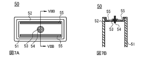
- the rectangular sealed battery disclosed in Patent Documents 1 and 2 below will be described with reference to FIGS. 7A is a plan view seen from the sealing plate side of the rectangular sealed battery disclosed in Patent Document 1 below, and FIG. 7B is a cross-sectional view taken along the line VIIB-VIIB in FIG. 7A.
- FIG. 8A is a plan view seen from the sealing plate side of the rectangular sealed battery disclosed in Patent Document 2 below, and FIG. 8B is a cross-sectional view taken along the line VIIIB-VIIIB of FIG. 8A.
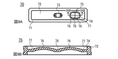
- 9A is a plan view seen from the sealing plate side of the rectangular sealed battery disclosed in Patent Document 3 below, and FIG. 9B is an enlarged cross-sectional view taken along line IXB-IXB in FIG. 9A.
- the rectangular sealed battery 50 disclosed in Patent Document 1 below includes an outer can 51 and a metal sealing plate 52, and a power generation element (not shown) is provided in the outer can 51. Has been inserted.
- the sealing plate 52 is welded to the opening of the outer can 51, and the terminal 54 is disposed in the through hole formed in the sealing plate 52 via the insulating member 53.
- the sealing plate 52 has a thin groove portion having a V-shaped cross section as shown in FIG. 7B in the central portion along the long side direction of the sealing plate 52 at one end in the short side direction of the sealing plate 52. 55 is formed.
- this rectangular sealed battery 50 when the internal pressure inside the battery rises and the outer can 51 slightly swells, the thin groove portion 55 is cracked to form an opening, and the gas inside the battery is easily released to the outside. Therefore, the battery can be prevented from rupturing and safety can be improved.
- the rectangular sealed battery 60 disclosed in the following Patent Document 2 includes an outer can 61 and a metal sealing plate 62, and a power generation element (illustrated) is included in the outer can 61. (Omitted) is inserted.
- the sealing plate 62 is welded to the opening of the outer can 61, and a terminal extraction portion 63 is formed at the center.
- a thin portion 64 is formed at the central portion along the long side direction of the sealing plate 62 at one end portion in the short side direction of the sealing plate 62.
- the dashed-dotted line part in FIG. 8B has shown the shape when the square sealed battery 60 expands.
- this rectangular sealed battery 60 when the internal pressure inside the battery rises and the outer can 61 slightly swells, the thin portion 64 is cracked to form an opening, and the gas inside the battery is easily released to the outside. Therefore, the battery can be prevented from rupturing and safety can be improved.
- the rectangular sealed battery 70 disclosed in Patent Document 3 includes an outer can 71 and a metal sealing plate 72, and a power generation element (illustrated) is included in the outer can 71. (Omitted) is inserted.
- the sealing plate 72 is welded to the opening of the outer can 71, and a terminal 73 is formed at the center.
- An opening hole 74 is formed in the center of the short side direction on one end side in the long side direction of the sealing plate 72, and is formed integrally with the sealing plate 72 in the opening hole 74.
- a safety valve 75 made of a thin valve body is formed.
- the safety valve 75 has a planar shape, for example, an oval shape, and is formed with two dome-shaped portions 76 that form a dome shape that swells outward from the battery, and a cross-sectional shape around these dome-shaped portions 76.
- a V-shaped crushing groove 77 is formed, and a central portion of the safety valve 75 between the two dome-shaped portions 76 has a V-shaped cross section along the short side of the sealing plate.
- a crushing auxiliary groove 78 is formed. According to this rectangular sealed battery 70, when the internal pressure inside the battery rises, the crushing groove 77 of the safety valve opens and the gas inside the battery is easily released to the outside. It can be improved.
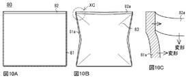
- FIG. 10A is a front sectional view of a conventional rectangular sealed battery
- FIG. 10B is a schematic front view when the internal pressure of the battery is increased and deformed
- FIG. 10C is an XC partial enlarged sectional view of FIG. 10B.
- illustration is abbreviate
- the rectangular sealed battery 80 has a configuration in which a flat sealing plate 82 is fitted into an opening of a rectangular outer can 81, and this fitting portion is laser-welded.
- the outer can 81 expands due to an increase in internal pressure
- the wide side 83 of the outer can 81 expands toward the outside of the battery, so that Are deformed so as to be constricted as shown in FIG. 10B and FIG. 10C, which causes the narrow side surfaces 81a and 82a other than the wide side surfaces of the outer can 81 and the sealing plate 82 to warp in a valley.
- the present invention operates as a safety valve formed on the sealing plate when an excessive increase in internal pressure occurs due to gas generation when exposed to high temperatures or when inappropriate charging / discharging is performed.
- the open area of the part is increased to reduce the gas discharge intensity inside the battery, and it is discharged with a discharge time equivalent to that of the conventional example or with a shorter discharge time.
- An object is to provide a prismatic sealed battery.
- a rectangular sealed battery of the present invention includes a rectangular bottomed outer can having an opening, a sealing plate that seals the opening, an electrode body disposed in the outer can, and a non-aqueous battery.
- Each of the sealing plates has a pair of long sides and short sides, On the front side or back side of the sealing plate, a groove-shaped first thin portion that operates as a cleavage portion is formed along the long side of one side of the sealing plate, A second thin portion is formed between the pair of long sides on at least one side of the short side of the sealing plate.
- the front side or the back side of the sealing plate has a groove-like shape that operates as a cleavage portion along the long side on one side of the sealing plate and between a pair of short sides.
- a first thin part is formed, and a second thin part is formed between a pair of long sides on at least one side of the short side of the sealing plate.
- the groove-shaped first thin portion is cleaved from the bottom of the groove when the swelling of the battery increases, so that an opening is formed and operates as a safety valve.
- the strength of the portion where the second thin portion is formed is weaker than the peripheral portion of the second thin portion, the portion is easily deformed when the battery swells.
- the second thin portion may be provided between the pair of long sides on both sides of the short side depending on the size of the rectangular sealed battery, but is not preferable because the strength of the rectangular sealed battery is reduced.
- the rectangular sealed battery according to the present invention when the pressure inside the battery is increased, the side surface having a large area of the outer can is swollen and the side surface having a small area around it is warped, and the sealing plate is in the second thin portion. Due to the large deformation, the shape of the second thin portion can advance the opening timing of the groove-shaped first thin portion or increase the opening area when the groove is opened, as compared with the conventional case. . Therefore, according to the rectangular sealed battery of the present invention, when the pressure inside the battery is increased and the groove-shaped first thin part is cleaved to operate as a safety valve, the discharge strength of the gas inside the battery is reduced. Since the gas inside the battery is discharged in a discharge time equivalent to or shorter than that of the conventional example, a prismatic sealed battery in which safety is ensured compared to that of the conventional example can be obtained.
- the “front surface” of the sealing plate means a surface on the outer side of the battery
- the “back surface” is also used to mean a surface on the inner side of the battery. That is, in the rectangular sealed battery of the present invention, the first and second thin portions may be formed on either the front surface or the back surface of the sealing plate, respectively, both on the same surface side or on different surface sides. It may be formed.
- the groove-shaped first thin portion is 1/3 or more of the length of the long side of the sealing plate.
- the pressure inside the battery increases and the groove-shaped thin portion is formed when the groove-shaped thin portion operates as a safety valve. Since the size of the opening to be reduced becomes small, the gas discharge strength becomes high and the gas discharge time becomes long, so that the safety is lowered.
- the groove-like thin portion may be formed across a pair of short sides.
- the second thin portion is formed so as to intersect the groove-shaped first thin portion.
- the groove-shaped first portion is formed at the intersection of the second thin portion and the groove-shaped first thin portion.
- the one thin portion is easily cleaved, and the sealing plate is easily deformed along the second thin portion.
- the second thin portion may be formed so as not to intersect the groove-shaped first thin portion.
- the sealing plate is formed at the second thin portion as compared with the case where the second thin portion is not formed. Becomes easy to deform.
- the square sealed battery of this invention when the pressure inside a battery becomes high, when a groove-shaped 1st thin part opens largely as a safety valve, and the 2nd thin part is not formed, In comparison, the discharge intensity of the gas inside the battery is reduced, and the gas inside the battery is discharged in a short discharge time, so that a prismatic sealed battery with secured safety can be obtained.
- the second thin portion is formed wider than the groove-shaped first thin portion.
- the second thin portion has a narrow groove-like portion that intersects the first thin portion, and is wider than the thin groove-like portion and does not intersect the first thin portion. It is preferable that the engraved portions are formed so as to at least partially overlap each other.
- the second thin-walled portion has a narrow groove-like portion that intersects with the first thin-walled portion, and an engraving that is wider than the thin groove-like portion and does not intersect with the first thin-walled portion. Since both of the parts are provided, the timing of the tearing is accelerated by the narrow groove-like part intersecting with the first thin part, and the size of the opening is increased by the engraved part not intersecting with the first thin part, and the square sealing A rectangular sealed battery in which the effects of the present invention are particularly remarkably exhibited while suppressing a decrease in battery strength can be obtained.
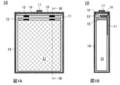
- FIG. 1A is a schematic view showing the inside of a rectangular sealed battery common to each of the examples and the comparative examples as seen through from the surface side
- FIG. 1B is a schematic cross-sectional view taken along line IB-IB in FIG. 1A
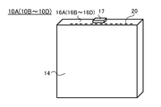
- 1 is a perspective view of a rectangular sealed battery common to Examples 1 to 3 and Comparative Example 1.
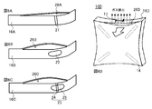
- FIG. 3A is a side view of the sealing plate of the rectangular sealed battery of Example 1, and FIG. 3B is the same bottom view.
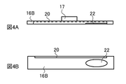
- 4A is a side view of the sealing plate of the rectangular sealed battery of Example 2, and FIG. 4B is the same bottom view.
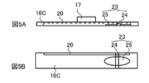
- FIG. 5A is a side view of the sealing plate of the rectangular sealed battery of Example 3, and FIG. 5B is the same bottom view.
- FIG. 6A to 6C are perspective views schematically showing states of the sealing plates of the rectangular sealed batteries of Examples 1 to 3 after the heating test, respectively, and FIG. 6D is a modification after the heating test of the rectangular sealed batteries of Comparative Example 1. It is a perspective view which shows the outline of a state.
- FIG. 7A is a plan view seen from the sealing plate side of the first conventional prismatic sealed battery, and FIG. 7B is a cross-sectional view taken along the line VIIB-VIIB in FIG. 7A.
- FIG. 8A is a plan view seen from the sealing plate side of the square sealed battery of the second conventional example, and FIG. 8B is a cross-sectional view taken along line VIIIB-VIIIB of FIG. 8A.
- FIG. 7A is a plan view seen from the sealing plate side of the first conventional prismatic sealed battery
- FIG. 7B is a cross-sectional view taken along the line VIIB-VIIB in FIG. 7A
- FIG. 8A is a plan view seen from the sealing plate
- FIG. 9A is a plan view seen from the sealing plate side of the third conventional prismatic sealed battery, and FIG. 9B is an enlarged cross-sectional view taken along the line IXB-IXB in FIG. 9A.
- FIG. 10A is a front cross-sectional view of a conventional rectangular sealed battery
- FIG. 10B is a schematic front view when the internal pressure of the battery rises and deforms
- FIG. 10C is an XC partial enlarged cross-sectional view of FIG. 10B.
- FIG. 1A is a schematic view showing the inside of a rectangular sealed battery common to each of the examples and the comparative examples as seen through from the surface side
- FIG. 1B is a schematic cross-sectional view taken along line IB-IB in FIG. 1A. is there.
- This non-aqueous electrolyte secondary battery 10 has a flat wound electrode body 13 in which a positive electrode plate having a positive electrode tab 11 and a negative electrode plate having a negative electrode tab 12 are wound via a separator.
- a flat wound electrode body 13 is accommodated in a rectangular outer can 14.
- a spacer 15 made of an insulating material is disposed on the flat wound electrode body 13, and a sealing plate 16 having an insulating plate 18 formed on the inner surface is fitted in the opening of the rectangular outer can 14.
- the fitting portion between the square outer can 14 and the sealing plate 16 is welded and sealed, for example, by laser welding.
- the positive electrode tab 11 and the negative electrode tab 12 protrude in the same direction (upward in FIGS. 1A and 1B), and the negative electrode tab 12 has a slit-like shape formed in the spacer 15. It passes through an opening (not shown) and is electrically connected to the negative electrode terminal 17 via a negative electrode lead (not shown) on the insulating plate 18. Further, the positive electrode tab 11 is passed between the spacer 15 and the outer can 14, a bent portion 11 ′ (see FIG. 1B) is formed between the spacer 15 and the insulating plate 18, and an end portion is connected to the outer can 14. It is sandwiched between the sealing plate 16 and the outer can 14 and the sealing plate 16 and is integrally welded. Note that the bent portion 11 ′ of the positive electrode tab 11 is applied to the positive electrode tab 11 even when the flat wound electrode body 13 moves inside the outer can 14 when an impact is applied to the nonaqueous electrolyte secondary battery 10. It is formed to absorb impact.
- the flat wound electrode body 13 common to each Example and Comparative Example was produced as follows. First, 94 parts by mass of lithium cobaltate, 3 parts by mass of a conductive agent, 3 parts by mass of a binder, and a slurry dispersed in N-methylpyrrolidone were applied to both sides of an aluminum foil. After drying, using a rolling roll It rolled until it became a predetermined packing density, and it cut
- the positive electrode plate and the negative electrode plate are wound by a winder with a microporous membrane separator made of a polyolefin resin interposed therebetween, and an insulating winding tape is attached and pressed to form a flat wound electrode.
- the body 13 was completed.
- a resin spacer 15 was placed on the flat wound electrode body 13, the negative electrode tab 12 was passed through one through hole of the spacer, and was welded to the negative electrode terminal 17 of the sealing plate 16. Further, the positive electrode tab 11 is bent on the other through-hole of the spacer 15, the positive electrode tab 11 is placed along the side surface of the sealing plate 16, and it is inserted into the bottomed rectangular outer can 14, and the sealing plate 16 and the outer can The positive electrode tab 11 was sandwiched between 14 fitting portions and sealed by laser welding.
- a mixed solvent is prepared so as to be 30% by volume of ethylene carbonate, 50% by volume of ethyl methyl carbonate, and 20% by volume of diethyl carbonate, and an electrolytic solution in which 1 mol / L of LiPF 6 is dissolved therein is used as an electrolyte.
- a predetermined amount was injected from the mouth (not shown), a sealing plug was inserted into the liquid injection port, and fixed by laser welding.
- the thickness of the sealing plate 16 is 0.8 mm
- the thickness of the aluminum alloy material of the outer can is 0.20 mm
- the sizes of the produced batteries are all thickness: 4.5 mm ⁇ width: 44 mm ⁇ height. : 56 mm. Therefore, the width (short side length) of the sealing plate 16 is 4.1 mm, and the length (long side length) is 43.6 mm.
- FIG. 2 is a perspective view of a rectangular sealed battery in common with Examples 1 to 3 described below.
- the rectangular sealed battery 10D of Comparative Example 1 As the rectangular sealed battery 10D of Comparative Example 1, as a cleavage part, on the back side of the sealing plate 16D, that is, on the inner side of the battery, along the long side on one side of the sealing plate 16D, at the center between a pair of short sides. A groove-shaped first thin-walled portion 20 that is actuated was formed, and a second thin-walled portion was not formed.
- the first groove-shaped thin portion 20 has a length of 37 mm, a width of 0.1 mm, and a depth of 0.7 mm at one end of the sealing plate 16 (thickness of the remaining portion is 0.1 mm). It is formed to become.
- the first groove-shaped thin portion 20 serves as a cleavage portion that operates as a safety valve when the pressure inside the battery increases.
- a rectangular sealed battery (not shown) of Comparative Example 2 in the rectangular sealed battery of Comparative Example 1, a shape similar to that disclosed in Patent Document 3 on one short side of the sealing plate 16 ( However, a safety valve in which the dome-shaped portion bulges inside the battery and the V-shaped crushing groove is formed inside the battery was used.
- This safety valve is composed of an elliptical thin portion of 1.9 mm ⁇ 5.2 mm, and the thickness of the remaining portion is 0.04 mm.
- FIG. 2 is a perspective view of a square sealed battery common to Examples 1 to 3 and Comparative Example 1 described above.
- 3A is a side view of the sealing plate of the rectangular sealed battery of Example 1
- FIG. 3B is a bottom view of the same.
- 4A is a side view of the sealing plate of the rectangular sealed battery of Example 2
- FIG. 4B is a bottom view of the same.
- FIG. 5A is a side view of the sealing plate of the rectangular sealed battery of Example 3
- FIG. 5B is a bottom view of the same. 2 to 5, the same components as those of the square sealed battery shown in FIG. 1 are denoted by the same reference numerals, and detailed description thereof is omitted.
- the rectangular sealed batteries 10A to 10C of Examples 1 to 3 each have a rectangular outer can 14, a sealing plate 16 welded to the opening of the rectangular outer can 14, and a negative electrode formed at substantially the center of the sealing plate 16. And a terminal 17.
- the sealing plate 16 has a groove-shaped first that operates as a cleaving portion on the back side, that is, on the inner side of the battery, along the long side on one side of the sealing plate 16 and in the center between the pair of short sides.
- the thin-walled portion 20 is formed.
- the first groove-shaped thin portion 20 is formed in common with the sealing plates 16A to 16C of the rectangular sealed batteries 10A to 10C of Examples 1 to 3, and the sealing plate is similar to Comparative Example 1.
- a length of 37 mm, a width of 0.1 mm, and a depth of 0.7 mm (thickness of remaining portion 0.1 mm) are formed at a position 0.2 mm away from one long side of 16.
- the first groove-shaped thin portion 20 serves as a cleavage portion that operates as a safety valve when the pressure inside the battery increases.
- the sealing plate 16 ⁇ / b> A in the rectangular sealed battery 10 ⁇ / b> A of the first embodiment substantially intersects the groove-shaped first thin portion 20 and between the long sides of the sealing plate 16 ⁇ / b> A.
- a groove-shaped second thin part having a width of 1 mm and a remaining part thickness of 0.4 mm so that the center is located at a position 13.5 mm away from the center of the sealing plate 16 ⁇ / b> A to one short side. 21 is formed.
- the above-mentioned dimension of 13.5 mm is derived from the observation results of many conventional rectangular sealed batteries in which the swelling of the battery is large, and is a dimension corresponding to a position where the sealing plate 16A is easily deformed. is there.
- the sealing plate 16B in the rectangular sealed battery 10B of Example 2 is substantially parallel to the groove-shaped first thin portion 20 and the central portion between the long sides of the sealing plate 16A.
- an elliptical shape having a major axis of 5.5 mm, a minor axis of 2.2 mm, and a remaining portion thickness of 0.1 mm so that the center is located at a position 13.5 mm away from the center of the sealing plate 16B on one short side.
- the engraving portion 22 is formed. This engraved portion 22 corresponds to the second thin portion of the present invention.
- the sealing plate 16C in the rectangular sealed battery 10C of Example 3 is a shape in which the groove-shaped second thin part 21 of Example 1 and the engraved part 22 of Example 2 are combined as shown in FIG.
- the second thin portion 23 is formed. That is, 13.5 mm apart from the center of the sealing plate 16C to one short side so as to substantially cross the groove-shaped first thin portion 20 and straddle between the long sides of the sealing plate 16C.
- a groove-like thin portion 24 having a width of 1 mm and a thickness of the remaining portion of 0.4 mm is formed so that the center is the center, and substantially parallel to the groove-like first thin portion 20, and The major axis is 5.5 mm, the minor axis is 2.2 mm, and the remaining thickness is such that the center part between the long sides of the sealing plate 16C is centered at a position 13.5 mm away from the center of the sealing plate 16C on one short side.
- An engraved portion 25 having a thickness of 0.1 mm is formed.
- the working pressure is based on the square sealed battery of Comparative Example 1 that does not form the second thin portion, and the square sealed battery of Comparative Example 2 having the conventional safety valve has the lowest working pressure.
- the operating pressure was also reduced in the three square sealed batteries 10A to 10C.
- the operating pressure of the rectangular sealed battery 10A of Example 1 is lower than that of Example 2.
- the engraved portion 22 corresponding to the second thin portion of the second embodiment does not intersect the groove-shaped first thin portion 20, whereas the groove-shaped second portion of the first embodiment.
- the thin-walled portion 20A is formed so as to substantially intersect with the groove-shaped first thin-walled portion 20 and straddle between the long sides of the sealing plate 16A.
- the sealing plate 16A is easy to cleave the groove-shaped first thin portion 20 at the intersection of the groove-shaped first thin portion 20 and the groove-shaped second thin portion 21, and the groove-shaped first thin portion 20 It seems that it became easy to bend along the 2 thin part 21.
- FIGS. 6A to 6C The state of the openings formed in the sealing plates 16A to 16C of Examples 1 to 3 after the heating test is shown in FIGS. 6A to 6C, respectively, and the square sealing of Comparative Example 1 in which the second thin portion is not formed in the sealing plate 16
- FIG. 6D The shape after the heating test in battery 10D is shown in FIG. 6D.
- the open area is about 10 mm 2 and the gas is discharged.
- the intensity was the strongest and the gas discharge time was the longest at 3.5 seconds.
- the gas discharge strength is reduced and the gas discharge time is also shorter than that of the comparative example 1.
- the groove-shaped first thin portion 20 formed on the sealing plate 16 is easily cleaved, but the area of the groove-shaped second thin portion 21 is small, so that the sealing The contribution to the bending deformation of the plate 16 was small, and the open portion 26A was formed in a shape as shown in FIG. 6B.
- the area of the open portion 26A is about 14 mm 2 which is slightly larger than those of Comparative Examples 1 and 2, and the gas discharge strength is more than that of Comparative Examples 1 and 2.
- the gas discharge time was 3 seconds as in the case of Comparative Example 2 provided with a conventional safety valve.
- Example 2 since the area of the second thin portion was larger than that of Example 1, the open portion 26B was formed in the shape shown in FIG. 6C.
- Example In the second prismatic sealed battery 10B since the sealing plate 16 has a large degree of curvature than that of Example 1, it becomes much greater than in the area of the opening portion 26B is approximately 150 mm 2 Example 1, gas The gas discharge time was weakened and the gas discharge time was also shortened to 1.5 seconds.
- the sealing plate 16 is more easily bent than in the case of Example 1, and Since the groove-shaped first thin portion 20 is easily cleaved, the area of the open portion 26C is about 155 mm 2, which is larger than that of the second embodiment, the gas discharge strength is weakened, and the gas discharge time is also reduced. It was the shortest at 1.0 seconds.
- the second thin portion is formed in a groove shape so as to intersect with the groove-shaped first thin portion 20 as in the rectangular sealed battery 10A of Example 1. However, it is better to form a large area without crossing the groove-shaped first thin portion 20 as in the rectangular sealed battery 10B of the second embodiment.
- the length of the groove-shaped first thin portion 20 that operates as a safety valve varies depending on the size of the rectangular sealed battery, but if it is 1/3 or more of the length of the sealing plate, the length of the sealing plate can be reduced. Good.
- the position of the first thin portion 20 in the direction of the short side of the sealing plate may be the end of the long side of the sealing plate (that is, the state where the end of the sealing plate is stepped) as in the above embodiment, You may provide between 1/3 of the length of a short side from a long side edge part.
- the width of the first thin portion is preferably 0.05 mm to 1/3 of the short side length.
- the depth of the groove of the groove-shaped first thin portion may be such that the thickness of the bottom portion is 0.05 mm to about 1 ⁇ 2 of the thickness of the sealing plate.
- the shape of the sealing plate in plan view is not necessarily rectangular, and the short side portion may be formed in a curved shape.
- the second thin-walled portion is a groove-shaped first thin-walled portion so that the center is located at a position divided by 1/3 to 1/7 of the long-side length from the long-side end of the sealing plate.
- the short side direction of the sealing plate is 0.1 mm to the same length as the short side of the sealing plate
- the long side direction of the sealing plate is 0.5 mm to about 1/3 of the long side length of the sealing plate.
- the sealing plate long side direction is 1 mm to about 1/2 the length of the sealing plate length
- the sealing plate short side direction is 1 mm. It can be formed until the position is 0.5 mm from the long side end (on the long side) of the sealing plate.
- the thickness of the remaining thin portion of the second thin portion may be set to 1/2 to 1/20 of the thickness of the sealing plate.
- the shape of the second thin-walled portion may be not only an elliptical shape but also a long hole shape or a rectangular shape when formed as a carved portion.
- the groove-shaped first thin portion 20 and the second thin portion may be provided on both the left and right sides in the long side direction from the center of the sealing plate, or may be provided only on one side of the left and right. Either the back surface or the front surface of the sealing plate may be used, and it may be provided on both the front surface and the back surface. However, it is preferable that the groove-shaped first thin portion 20 and the second thin portion have the respective grooves or engraved portions formed on the same side of the sealing plate.
- the materials of the outer can and sealing plate can be selected from various metals and alloys in consideration of the electrochemical characteristics of the electrode plate and electrolyte stored in the outer can, but aluminum and aluminum alloys are relatively easy to process. It is preferable because the effects of the present invention are easily obtained.
- Non-aqueous electrolyte secondary battery 10A-10D ... Square sealed battery 11 ... Positive electrode tab 11 '... Bending part 12 ; Negative electrode tab 13 ... Flat wound electrode body 14 ... Exterior can 15 ... Spacer 16, 16A-16D ... Sealing plate 17 ... Negative electrode terminal 18 ... Insulating plate 20 ... First thin part 21 ... Grooved second thin part 22 ... Engraved part 23 ... Second thin part 24 ... Grooved thin part 25 ... Engraved part 26A ⁇ 26D ... Open part
Landscapes
- Chemical & Material Sciences (AREA)
- Chemical Kinetics & Catalysis (AREA)
- Electrochemistry (AREA)
- General Chemical & Material Sciences (AREA)
- Gas Exhaust Devices For Batteries (AREA)
- Sealing Battery Cases Or Jackets (AREA)
Abstract
【課題】封口板に形成された安全弁として作動する部分の開放面積が大きくなるようにして、電池内部のガスの排出強度が小さくなるようにすると共に排出時間で排出されるようにした、安全性に優れた角形密閉電池を提供すること。 【解決手段】本発明の角形密閉電池は、封口板16Aに、電池内部の圧力が上昇した際に安全弁として作動する開裂部となる溝状の第1の薄肉部20と、この溝状の第1の薄肉部の開裂タイミングを早めたり、開裂したときの開口面積を大きくしたりするよ うに形成された第2の薄肉部21が形成されている。
Description
本発明は、角形密閉電池に関し、特に、ガス発生による内圧の上昇が生じた際に、封口板に形成された安全弁として作動する部分の開放面積が大きくなるようにして、電池内部のガスの排出強度が小さくなるようにすると共に短時間で排出されるようにした、安全性に優れた角形密閉電池に関する。
今日の携帯電話機、携帯型パーソナルコンピュータ、携帯型音楽プレイヤー等の携帯型電子機器の駆動電源として、高エネルギー密度を有し、高容量であるリチウムイオン二次電池に代表される非水電解質二次電池が広く利用されている。中でも、負極活物質として黒鉛粒子を用いた非水電解質二次電池は、安全性が高く、かつ、高容量であるために広く用いられている。この種の非水電解質二次電池が使用される機器においては、電池を収容するスペースが角形形状であることが多いことから、偏平な巻回電極体ないし積層電極体を角形の外装缶に密閉状態で収容した角形密閉電池が多く使用されている。
ところで、非水電解質二次電池は、高温にさらされた場合や、適正でない充放電が行われた場合には、電極と電解液とが異常反応することにより電解液が分解しガスを発生することがあり、このときは電池内部の圧力(以下、電池内圧と呼ぶことがある)が上昇する。電池内圧の上昇が過度に進行すると、電池の破裂が起こりうる。そのため、非水電解質二次電池においては、円筒形のものであれ角形のものであれ、電池の内圧が所定値以上になった場合にこの内圧を外部に放出するために安全弁を設けることが行われている。
このような安全弁は、封口板に成形するタイプと、缶に成形するタイプに大別できる。封口板に成形するタイプの安全弁は、封口板上に配置される端子や注液構造を避けて配置する必要があり、安全弁の開放面積に対する制約が大きいが、近年の角形密閉電池の更なる薄型化及び幅広化の進展に伴い、ますます安全弁の開放面積を確保することが難しくなっている。一方、外装缶に成形するタイプの安全弁は、安全弁の開放面積が確保し易い利点がある反面、絞り加工により成形された電池外装缶の一面に加工する必要があるため、安全弁の機能に対する影響因子が複雑であるため、適正な安全弁の形成方法の適用を考慮する必要があり、しかも、安全弁の製造工程が複雑となるため、量産部品としては封口板へ安全弁を形成することが望まれている。
例えば、下記特許文献1及び2には、角形密閉電池の内圧の上昇を抑制するために、封口板に安全弁を形成した角形密閉電池が開示されている。ここで、下記特許文献1及び2に開示されている角形密閉電池を図7及び図8を用いて説明する。なお、図7Aは下記特許文献1に開示されている角形密閉電池の封口板側から見た平面図であり、図7Bは図7AのVIIB-VIIB線に沿った断面図である。図8Aは下記特許文献2に開示されている角形密閉電池の封口板側から見た平面図であり、図8Bは図8AのVIIIB-VIIIB線に沿った断面図である。また、図9Aは下記特許文献3に開示されている角形密閉電池の封口板側から見た平面図であり、図9Bは図9AのIXB-IXB線に沿った拡大断面図である。
下記特許文献1に開示されている角形密閉電池50は、図7に示したように、外装缶51と、金属製の封口板52とを有し、外装缶51内に発電要素(図示省略)が挿入されている。封口板52は外装缶51の開口部に溶接されており、この封口板52に形成された透孔に絶縁部材53を介して端子54が配置されている。そして、封口板52には、封口板52の短辺方向の一方側の端部において、封口板52の長辺方向に沿った中央部に、図7Bに示すように断面V字状の薄肉溝部55が形成されている。この角形密閉電池50によれば、電池内部の内圧が上昇して外装缶51が僅かに膨れると、薄肉溝部55に亀裂が入って開口が形成され、電池内部のガスが容易に外部に放出されるため、電池の破裂を防止でき、安全性の向上を図ることができるというものである。
また、下記特許文献2に開示されている角形密閉電池60は、図8に示したように、外装缶61と、金属製の封口板62とを有し、外装缶61内に発電要素(図示省略)が挿入されている。封口板62は、外装缶61の開口部に溶接されており、中央部に端子取出し部63が形成されている。そして、封口板62の溶接部の近傍には、封口板62の短辺方向の一方側の端部において、封口板62の長辺方向に沿った中央部に、薄肉部64が形成されている。なお、図8Bにおける一点鎖線部分は角形密閉電池60が膨化した際の形状を示している。この角形密閉電池60によれば、電池内部の内圧が上昇して外装缶61が僅かに膨れると、薄肉部64に亀裂が入って開口が形成され、電池内部のガスが容易に外部に放出されるため、電池の破裂を防止でき、安全性の向上を図ることができるというものである。
さらに、下記特許文献3に開示されている角形密閉電池70は、図9に示したように、外装缶71と、金属製の封口板72とを有し、外装缶71内に発電要素(図示省略)が挿入されている。封口板72は、外装缶71の開口部に溶接されており、中央部に端子73が形成されている。そして、封口板72の長辺方向の一方の端部側で、短辺方向の中央部には、開放孔74が形成されており、この開放孔74内に封口板72と一体に形成された薄肉の弁体からなる安全弁75が形成されている。この安全弁75は、平面形状が例えば小判状となされており、電池外側方向に膨らんでドーム形状をなすドーム状部76が2個形成されており、これらのドーム状部76の周囲には断面形状がV字状の破砕溝77が形成されており、また,二つのドーム状部76間で安全弁75の中央部には、封口板の短辺に沿って断面形状がV字状の直線状の破砕補助溝78が形成されている。この角形密閉電池70によれば、電池内部の内圧が上昇すると、安全弁の破砕溝77が開口して電池内部のガスが容易に外部に放出されるため、電池の破裂を防止でき、安全性の向上を図ることができるというものである。
上記特許文献1~3に開示されている角形密閉電池によれば、電池内圧が上昇したときには、封口板に形成された薄肉部ないし安全弁に開口が形成されるため、一応、電池内部のガスが容易に外部に放出され、電池の破裂を防止でき、安全性の向上を図ることができる。しかしながら、いずれの構造の角形密閉電池でも薄肉部や安全弁に形成された開口の面積が小さ過ぎてガスの排出強度が大きく、しかもガスの放出時間が長くなるので、安全性の確保が十分ではないという課題が存在している。
ここで、従来の角形密閉電池の内圧の上昇による外装缶の膨化現象を図10を用いて説明する。なお図10Aは従来の角形密閉電池の正面断面図であり、図10Bは電池内圧が上昇して変形した際の模式正面図であり、図10Cは図10BのXC部分拡大断面図である。なお、図10においては、封口板及び角形外装缶以外の構成は図示省略してある。
図10Aに示すように、角形密閉電池80は、角形の外装缶81の開口部に平板状の封口板82が嵌合され、この嵌合部がレーザ溶接された構成を備えている。このような角形密閉電池80においては、内圧が大きくなって外装缶81が膨化する際、外装缶81の面積の広い側面83が電池外側に向かって膨化するのに伴い、面積の広い側面の周囲の辺が図10Bや図10Cに示すようにくびれるように変形し、それが外装缶81及び封口板82の面積の広い側面以外の面積の狭い側面81aや82aを谷ゾリに反らせる。
そのため、角形密閉電池の封口板に形成する安全弁としては、図10に示したような電池の変形を考慮して、電池内圧が増加して安全弁が作動した場合には、安全弁の開口面積が大きくなるようにして、電池内部のガスの排出強度(ガス排出の勢い)が小さくなるようにすると共に、電池内部のガスの排出が短時間で行われるようにすることが要望される。
発明者等は、上述の従来技術の問題点を解決すべく種々検討を重ねた結果、単に封口板の長辺方向に沿った中央部において、短辺方向の一方側の端部に、溝状の薄肉部を形成するだけでなく、封口板の短辺方向の中央部に上述のような従来の溝状の薄肉部よりも幅広の彫り込み部を形成することにより解決し得ることを見出し、本発明を完成するに至ったのである。
すなわち、本発明は、高温にさらされた場合や、適正でない充放電が行われた場合等において、ガス発生による過度の内圧の上昇が生じた際に、封口板に形成された安全弁として作動する部分の開放面積が大きくなるようにして、電池内部のガスの排出強度が小さくなるようにすると共に、従来例のものと同等の排出時間ないしより短い排出時間で排出される、安全性に優れた角形密閉電池を提供することを目的とする。
上記目的を達成するため、本発明の角形密閉電池は、開口部を備える角形有底の外装缶と、前記開口部を封口する封口板と、前記外装缶内に配置された電極体及び非水電解液と、を備える角形密閉電池において、
前記封口板はそれぞれ一対の長辺と短辺とを有しており、
前記封口板の表面側又は裏面側には、前記封口板の一方側の長辺に沿って、開裂部として作動する溝状の第1の薄肉部が形成されており、
前記封口板の前記短辺の少なくとも一方側における前記一対の長辺間に、第2の薄肉部が形成されていることを特徴とする。
前記封口板はそれぞれ一対の長辺と短辺とを有しており、
前記封口板の表面側又は裏面側には、前記封口板の一方側の長辺に沿って、開裂部として作動する溝状の第1の薄肉部が形成されており、
前記封口板の前記短辺の少なくとも一方側における前記一対の長辺間に、第2の薄肉部が形成されていることを特徴とする。
本発明の角形密閉電池においては、封口板の表面側又は裏面側には、封口板の一方側の長辺に沿って、かつ一対の短辺間の間に、開裂部として作動する溝状の第1の薄肉部が形成されており、また、封口板の短辺の少なくとも一方側における一対の長辺間に第2の薄肉部が形成されている。このうち、溝状の第1の薄肉部は、電池の膨れが大きくなると溝の底から開裂して開口部が形成されて安全弁として作動する。また、第2の薄肉部が形成された箇所は、この第2の薄肉部の周囲部分よりも強度が弱くなるため、電池の膨れが大きくなると変形し易い。なお、第2の薄肉部は、角形密閉電池の大きさによって短辺の両側における一対の長辺間に設けてもよいが、角形密閉電池の強度が低下するため、好ましくない。
したがって、本発明の角形密閉電池においては、電池内部の圧力が高くなると、外装缶の面積の広い側面が膨れると共にその周囲の面積の狭い側面が谷反りし、封口板が第2の薄肉部において大きく変形するため、第2の薄肉部の形態により、従来例の場合に比して、溝状の第1の薄肉部の開裂タイミングを早めたり、開裂したときの開口面積を大きくすることができる。そのため、本発明の角形密閉電池によれば、電池内部の圧力が高くなって溝状の第1の薄肉部が開裂して安全弁として作動したとき、電池内部のガスの排出強度が低下し、しかも、電池内部のガスは従来例のものと同等の排出時間ないしより短い排出時間で排出されるようになるので、従来例のものよりも安全性が確保された角形密閉電池が得られる。
なお、本発明においては、封口板の「表面」とは電池の外部側の面を意味し、同じく「裏面」とは電池の内部側の面を意味するものとして使用されている。すなわち、本発明の角形密閉電池においては、第1及び第2の薄肉部は、それぞれ封口板の表面及び裏面のいずれに形成されていてもよく、両者とも同一面側でも、それぞれ異なる面側に形成されていてもよい。
また、本発明の角形密閉電池においては、前記溝状の第1の薄肉部は、前記封口板の長辺の長さの1/3以上であることが好ましい。
溝状の第1の薄肉部の長さが封口板の長辺の長さの1/3未満であると、電池内部の圧力が高くなって溝状の薄肉部が安全弁として作動した際、形成される開口の大きさが小さくなるので、ガスの排出強度が高くなると共にガスの排出時間も長くなるため、安全性が低下してしまう。なお、溝状の薄肉部は、一対の短辺に跨って形成されていてもよい。
また、本発明の角形密閉電池においては、前記第2の薄肉部は、前記溝状の第1の薄肉部と交差するように形成されていることが好ましい。
第2の薄肉部が前記溝状の第1の薄肉部と交差するように形成されていると、第2の薄肉部と前記溝状の第1の薄肉部との交差部で溝状の第1の薄肉部が開裂し易くなると共に、第2の薄肉部に沿って封口板が変形し易くなる。これにより、本発明の角形密閉電池によれば、電池内部の圧力が高くなって溝状の第1の薄肉部が安全弁として作動したとき、より電池内部のガスの排出強度が低下し、しかも、電池内部のガスは従来例のものよりも短い排出時間で排出されるようになるので、より安全性が確保された角形密閉電池が得られる。
また、本発明の角形密閉電池においては、前記第2の薄肉部は、前記溝状の第1の薄肉部と交差しないように形成されていてもよい。
第2の薄肉部が溝状の第1の薄肉部と交差しないように形成されていても、第2の薄肉部が形成されていない場合と比すると、第2の薄肉部の部分で封口板が変形し易くなる。これにより、本発明の角形密閉電池によれば、電池内部の圧力が高くなった際に溝状の第1の薄肉部が安全弁として大きく開口し、第2の薄肉部が形成されていない場合に比すると、電池内部のガスの排出強度が低下し、しかも、電池内部のガスは短い排出時間で排出されるようになるので、安全性が確保された角形密閉電池が得られる。
また、本発明の角形密閉電池においては、前記第2の薄肉部は、前記溝状の第1の薄肉部よりも幅広に形成されていることが好ましい。
前記第2の薄肉部が溝状の第1の薄肉部よりも封口板の短辺方向や長辺方向において幅広に形成されていると、封口板は第2の薄肉部で大きく変形し、開口が大きくなる。これにより、本発明の角形密閉電池によれば、より上記の本発明の効果が良好に奏される角形密閉電池が得られるようになる。
一方、第2の薄肉部の面積を過度に大きくすると角形密閉電池の強度が低下する可能性がある。そこで本発明の角形密閉電池においては、前記第2の薄肉部は、第1の薄肉部と交差する細い溝状部分と、前記細い溝状部分よりも幅広でかつ第1の薄肉部と交差しない彫り込み部からなり、互いに少なくとも部分的に重畳するように形成されていることが好ましい。
本発明の角形密閉電池によれば、第2の薄肉部が、第1の薄肉部と交差する細い溝状部分と、この細い溝状部分よりも幅広でかつ第1の薄肉部と交差しない彫り込み部の両者を備えているので、第1の薄肉部と交差する細い溝状部により開裂のタイミングが早くなり、第1の薄肉部と交差しない彫り込み部により開口の大きさが大きくなり、角形密閉電池の強度の低下を抑制しながら上記本発明の効果が特に顕著に奏される角形密閉電池が得られるようになる。
以下、本発明を実施するための形態を図面を用いて詳細に説明する。ただし、以下に示す実施形態は、本発明の技術的思想を具体化するための角形密閉電池を例示すものであって、本発明をこの実施形態に特定することを意図するものではなく、本発明は特許請求の範囲に示した技術思想を逸脱することなく種々の変更を行ったものにも均しく適用し得るものである。なお、この明細書における説明のために用いられた各図面においては、各部材を図面上で明確に認識できる程度の大きさとするため、各部材毎に縮尺を異ならせて表示しており、必ずしも実際の寸法に比例して表示されているものではない。
まず、各実施例及び比較例に共通する角形密閉電池の概略構成を図1を用いて説明する。なお、図1Aは各実施例及び比較例に共通する角形密閉電池の内部を表面側から透視して表した模式図であり、図1Bは図1AのIB-IB線に沿った模式断面図である。
この非水電解質二次電池10は、正極タブ11を有する正極極板と負極タブ12を有する負極極板とがセパレータを介して巻回された偏平状の巻回電極体13を有し、この偏平状の巻回電極体13が角形の外装缶14内に収容されている。偏平状の巻回電極体13の上部には、絶縁性材料からなるスペーサ15が配置され、更に角形の外装缶14の開口部は、内面に絶縁板18が形成されている封口板16が嵌合され、角形の外装缶14と封口板16との嵌合部が例えばレーザ溶接により溶接され、密閉されている。
この偏平状の巻回電極体13からは、正極タブ11及び負極タブ12が同一方向(図1A及び図1Bにおいて上方向)に突出され、負極タブ12は、スペーサ15に形成されたスリット状の開口(図示省略)内を通され、絶縁板18上の負極リード部(図示省略)を経て負極端子17に電気的に接続されている。また、正極タブ11は、スペーサ15と外装缶14との間を通され、スペーサ15及び絶縁板18との間で折り曲げ部11'(図1B参照)が形成され、端部が外装缶14と封口板16との間に挟まれて外装缶14及び封口板16と一体に溶接されている。なお、正極タブ11の折り曲げ部11'は、非水電解質二次電池10に衝撃が加わった場合、偏平状の巻回電極体13が外装缶14内部で動いたとしても、正極タブ11にかかる衝撃を吸収するために形成されるものである。
なお、各実施例及び比較例に共通する偏平状の巻回電極体13は次のようにして作製した。まず、コバルト酸リチウムを94質量部、導電剤を3質量部、結着剤を3質量部、N-メチルピロリドンに分散させたスラリーをアルミ箔の両面に塗布し、乾燥後に圧延ロールを用いて所定の充填密度となるまで圧延し、所定寸法に切断して正極極板を得た。また、黒鉛粉末を95質量部、増粘剤を3質量部、結着剤を2質量部、水に分散させたスラリーを銅箔の両面に塗布し、乾燥後に圧延ロールを用いて所定の充填密度となるまで圧延し、所定寸法に切断して負極極板を得た。次に、正極極板及び負極極板をポリオレフィン系樹脂からなる微多孔膜のセパレータを介在させて巻き取り機により巻回し、絶縁性の巻き止めテープを取り付け、プレスして偏平状の巻回電極体13を完成させた。
この偏平状の巻回電極体13の上に樹脂製のスペーサ15を設置し、スペーサの一つの透孔に負極タブ12を通し、封口板16の負極端子17に溶接した。また、スペーサ15のもう片方の透孔上で正極タブ11を折り曲げ、封口板16側面に正極タブ11を沿わせ、それを有底角形の外装缶14内に挿入し、封口板16と外装缶14の嵌合部に正極タブ11を挟みこみ、レーザ溶接にて封口した。そして、エチレンカーボネート30vol%、エチルメチルカーボネート50vol%、ジエチルカーボネート20vol%となるように混合溶媒を調製し、これにLiPF6を1mol/L溶解して電解質とした電解液を封口板16の注液口(図示省略)より所定量注入し、注液口に封止栓を挿入し、レーザ溶接にて固定した。
なお、封口板16の厚みは0.8mmであり、外装缶のアルミニウム合金材の厚さは0.20mmであり、作製した電池のサイズは、全て厚み:4.5mm×幅:44mm×高さ:56mmである。そのため、封口板16の幅(短辺の長さ)は4.1mmであり、長さ(長辺の長さ)は43.6mmである。
[比較例1、比較例2]
比較例1の角形密閉電池10Dの構成を図2を用いて説明する。なお、図2は以下で説明する実施例1~3と共通する角形密閉電池の斜視図である。比較例1の角形密閉電池10Dとしては、封口板16Dの裏面側、すなわち電池の内部側に、封口板16Dの一方側の長辺に沿って一対の短辺間の中央部に、開裂部として作動する溝状の第1の薄肉部20を形成し、第2の薄肉部を形成しないものを用いた。この第1の溝状の薄肉部20は、封口板16の一方の長辺端部に長さが37mm、幅が0.1mm、深さ0.7mm(残肉部の厚さ0.1mm)となるように形成されている。この第1の溝状の薄肉部20は、電池内部の圧力が上昇した際に安全弁として作動する開裂部となる。また、比較例2の角形密閉電池(図示省略)としては、比較例1の角形密閉電池において、封口板16の一方の短辺側に上記特許文献3に開示されているのと類似の形状(図9参照)であるが、ドーム状部が電池内側に膨出しており、V字状破砕溝が電池内部側に形成された安全弁を用いた。この安全弁は、1.9mm×5.2mmの楕円形状の薄肉部からなりその残肉部の厚さは0.04mmである。
比較例1の角形密閉電池10Dの構成を図2を用いて説明する。なお、図2は以下で説明する実施例1~3と共通する角形密閉電池の斜視図である。比較例1の角形密閉電池10Dとしては、封口板16Dの裏面側、すなわち電池の内部側に、封口板16Dの一方側の長辺に沿って一対の短辺間の中央部に、開裂部として作動する溝状の第1の薄肉部20を形成し、第2の薄肉部を形成しないものを用いた。この第1の溝状の薄肉部20は、封口板16の一方の長辺端部に長さが37mm、幅が0.1mm、深さ0.7mm(残肉部の厚さ0.1mm)となるように形成されている。この第1の溝状の薄肉部20は、電池内部の圧力が上昇した際に安全弁として作動する開裂部となる。また、比較例2の角形密閉電池(図示省略)としては、比較例1の角形密閉電池において、封口板16の一方の短辺側に上記特許文献3に開示されているのと類似の形状(図9参照)であるが、ドーム状部が電池内側に膨出しており、V字状破砕溝が電池内部側に形成された安全弁を用いた。この安全弁は、1.9mm×5.2mmの楕円形状の薄肉部からなりその残肉部の厚さは0.04mmである。
[実施例1~3]
実施例1~3の角形密閉電池の構成を図2~図5を用いて説明する。なお、図2は実施例1~3と上述の比較例1に共通する角形密閉電池の斜視図である。図3Aは実施例1の角形密閉電池の封口板の側面図であり、図3Bは同じく底面図である。図4Aは実施例2の角形密閉電池の封口板の側面図であり、図4Bは同じく底面図である。図5Aは実施例3の角形密閉電池の封口板の側面図であり、図5Bは同じく底面図である。また、図2~図5においては、図1に記載した角形密閉電池と同一の構成部分には同一の参照符号を付与して、その詳細な説明は省略する。
実施例1~3の角形密閉電池の構成を図2~図5を用いて説明する。なお、図2は実施例1~3と上述の比較例1に共通する角形密閉電池の斜視図である。図3Aは実施例1の角形密閉電池の封口板の側面図であり、図3Bは同じく底面図である。図4Aは実施例2の角形密閉電池の封口板の側面図であり、図4Bは同じく底面図である。図5Aは実施例3の角形密閉電池の封口板の側面図であり、図5Bは同じく底面図である。また、図2~図5においては、図1に記載した角形密閉電池と同一の構成部分には同一の参照符号を付与して、その詳細な説明は省略する。
実施例1~3の角形密閉電池10A~10Cは、それぞれ角形の外装缶14と、角形の外装缶14の開口に溶接された封口板16と、封口板16のほぼ中央部に形成された負極端子17とを備えている。そして、封口板16には、裏面側、すなわち電池の内部側に、封口板16の一方側の長辺に沿って一対の短辺間の中央部に、開裂部として作動する溝状の第1の薄肉部20が形成されている。この第1の溝状の薄肉部20は、実施例1~3の角形密閉電池10A~10Cの封口板16A~16Cに共通に形成されている構成であり、比較例1と同様に、封口板16の一方の長辺から0.2mm離間した位置に長さが37mm、幅が0.1mm、深さ0.7mm(残肉部の厚さ0.1mm)となるように形成されている。この第1の溝状の薄肉部20は、電池内部の圧力が上昇した際に安全弁として作動する開裂部となる。
実施例1の角形密閉電池10Aにおける封口板16Aは、図3に示したように、溝状の第1の薄肉部20と実質的に交差するように、かつ、封口板16Aの長辺間に跨るように、封口板16Aの中心から一方の短辺側に13.5mm離間した位置が中心となるように、幅1mm、残肉部の厚さ0.4mmの溝状の第2の薄肉部21が形成されている。なお、上記の13.5mmという寸法は、電池の膨れが大きくなった従来の多くの角形密閉電池の観測結果から導き出された、封口板16Aが変形しやすい位置に該当する寸法を採用したものである。
また、実施例2の角形密閉電池10Bにおける封口板16Bは、図4に示したように、溝状の第1の薄肉部20とほぼ並行に、かつ、封口板16Aの長辺間の中央部に、封口板16Bの中心から一方の短辺側に13.5mm離間した位置が中心となるように、長径5.5mm、短径2.2mm、残肉部の厚さ0.1mmの楕円形状の彫り込み部22が形成されている。この彫り込み部22が本発明の第2の薄肉部に対応する。
さらに、実施例3の角形密閉電池10Cにおける封口板16Cは、図3に示したように、実施例1の溝状の第2の薄肉部21と実施例2の彫り込み部22とを組み合わせた形状の第2の薄肉部23が形成されている。すなわち、溝状の第1の薄肉部20と実質的に交差するように、かつ、封口板16Cの長辺間に跨るように、封口板16Cの中心から一方の短辺側に13.5mm離間した位置が中心となるように、幅1mm、残肉部の厚さ0.4mmの溝状の薄肉部24が形成され、また、溝状の第1の薄肉部20とほぼ並行に、かつ、封口板16Cの長辺間の中央部に、封口板16Cの中心から一方の短辺側に13.5mm離間した位置が中心となるように、長径5.5mm、短径2.2mm、残肉部の厚さ0.1mmの彫り込み部25が形成されている。これらの溝状の薄肉部24及び彫り込み部25が実施例3の角形密閉電池の第2の薄肉部23を構成する。
[作動圧の測定]
最初に、電解液を注入しない以外は実施例1~3、比較例1及び2の角形密閉電池と同様にして作製されたダミー電池について、外装缶14の底部に穴を開け、この穴から窒素ガスを注入し、実施例1~3、及び、比較例1の各ダミー電池については溝状の第1の薄肉部20が開裂する際の圧力を、また、比較例2のダミー電池については、安全弁(図9参照)が開裂する際の圧力を、それぞれ測定した。なお、作動圧の測定値は、それぞれの場合について5個ずつ測定した平均値である。結果をまとめて表1に示した。
最初に、電解液を注入しない以外は実施例1~3、比較例1及び2の角形密閉電池と同様にして作製されたダミー電池について、外装缶14の底部に穴を開け、この穴から窒素ガスを注入し、実施例1~3、及び、比較例1の各ダミー電池については溝状の第1の薄肉部20が開裂する際の圧力を、また、比較例2のダミー電池については、安全弁(図9参照)が開裂する際の圧力を、それぞれ測定した。なお、作動圧の測定値は、それぞれの場合について5個ずつ測定した平均値である。結果をまとめて表1に示した。
[加熱試験]
上述のようにして作製された実施例1~3、比較例1及び2の角形密閉電池について、250℃に維持されたホットプレート上に1個づつ載置して加熱した。そして、それぞれの角形密閉電池の一部が開裂し、内部のガスが排出された際の勢い及び排出時間を測定した。なお、加熱試験の測定値は、それぞれの場合について5個ずつ測定した平均値である。結果をまとめて表1に示した。
上述のようにして作製された実施例1~3、比較例1及び2の角形密閉電池について、250℃に維持されたホットプレート上に1個づつ載置して加熱した。そして、それぞれの角形密閉電池の一部が開裂し、内部のガスが排出された際の勢い及び排出時間を測定した。なお、加熱試験の測定値は、それぞれの場合について5個ずつ測定した平均値である。結果をまとめて表1に示した。

表1に示した結果から以下のことが分かる。作動圧力は、第2の薄肉部を形成しない比較例1の角形密閉電池を基準とすると、従来の安全弁を形成した比較例2の角形密閉電池が最も作動圧が低かったが、実施例1~3の角形密閉電池10A~10Cでも作動圧は低下していた。このうち実施例1及び2の測定結果を対比すると、実施例1の角形密閉電池10Aの作動圧は実施例2のものよりも低くなっている。このような結果は、実施例2の第2の薄肉部に対応する彫り込み部22は溝状の第1の薄肉部20とは交差していないのに対し、実施例1の溝状の第2の薄肉部20Aは溝状の第1の薄肉部20と実質的に交差するようにかつ封口板16Aの長辺間に跨るように形成されているため、実施例1の角形密閉電池10Aでの封口板16Aは、溝状の第1の薄肉部20と溝状の第2の薄肉部21の交差部で、溝状の第1の薄肉部20が開裂し易くなり、また、溝状の第2の薄肉部21に沿って曲がり易くなったためと思われる。
これに対し、実施例1の溝状の第2の薄肉部21及び実施例2の彫り込み部22の両方の構成を備えている実施例3の角形密閉電池10Cでは、最も作動圧が低くなっている。この結果は、実施例1の結果と実施例2の結果が相乗的に表れたものと思われる。
また、加熱試験結果によれば、実施例1~3及び比較例2のいずれの構成によっても、封口板に第2の薄肉部を形成しない比較例1の場合と比すると、角形密閉電池の破裂防止効果が奏されている。しかしながら、角形密閉電池における内部燃焼時に発生するガスの量が膨大なため、比較例2のような従来形状の安全弁では、ガス排出の勢いが強く、しかも、安全弁の開放面積が約11mm2と狭いため、ガス排出時間は3秒程度と長くなった。
加熱試験後の実施例1~3の封口板16A~16Cに形成された開口の状態をそれぞれ図6A~図6Cに示し、封口板16に第2の薄肉部を形成しない比較例1の角形密閉電池10Dでの加熱試験後の形状を図6Dに示す。比較例1の角形密閉電池10Dでは、封口板16の変形にともない溝状の第1の薄肉部20が開裂して開放部26Dを形成するものの、開放面積は約10mm2であり、ガスの排出強度は最も強く、ガスの排出時間も3.5秒と最も長かった。
これに対し、溝状の第2の薄肉部を形成した実施例1~3の角形密閉電池では、比較例1のものよりも、ガスの排出強度が低下するとともにガスの排出時間も短くなっている。しかしながら、実施例1の角形密閉電池10Aでは、封口板16に形成された溝状の第1の薄肉部20は開裂し易いが、溝状の第2の薄肉部21の面積が狭いため、封口板16の曲がり変形への寄与が小さく、図6Bに示したような形状に開放部26Aが形成された。実施例1の角形密閉電池10Aでは、この開放部26Aの面積は約14mm2と比較例1及び2の場合より僅かにしか大きくなく、ガスの排出強度は比較例1及び比較例2の場合よりも弱かったが、ガスの排出時間は従来の安全弁を設けた比較例2の場合と同様の3秒となった。
また、実施例2の角形密閉電池10Bでは、第2の薄肉部の面積が実施例1の場合よりは広いため、図6Cに示したような形状に開放部26Bが形成された。実施例2の角形密閉電池10Bでは、封口板16は実施例1の場合より曲がりの程度が大きいため、開放部26Bの面積が約150mm2と実施例1の場合よりも大幅に大きくなり、ガスの排出強度が弱くなり、ガスの排出時間も1.5秒と短くなった。さらに、実施例1の第2の薄肉部と実施例2の第2の薄肉部とを組み合わせた実施例3の角形密閉電池10Cでは、封口板16は実施例1の場合より曲げやすくなり、しかも、溝状の第1の薄肉部20は開裂し易いため、開放部26Cの面積が約155mm2と実施例2の場合よりもさらに大きくなり、ガスの排出強度も弱くなり、ガスの排出時間も1.0秒と最も短くなった。
したがって、封口板に溝状の第1の薄肉部だけでなく、第2の薄肉部を適宜形成することにより、溝状の第1の薄肉部の開裂に必要な圧力を小さくすることができ、しかも、開放面積も大きくできるため、ガスの排出強度を弱くすることができるとともにガスの排出時間を短くすることができ、角形密閉電池の安全性向上の効果が良好に奏されることが分かる。ただし、表1に示した結果からすると、第2の薄肉部は、実施例1の角形密閉電池10Aのように溝状にして溝状の第1の薄肉部20と交差するように形成するよりも、実施例2の角形密閉電池10Bのように溝状の第1の薄肉部20と交差しなくても広い面積となるように形成した方がよい。
また、安全弁として作動する溝状の第1の薄肉部20の長さは、角形密閉電池のサイズによっても変化するが、封口板の長さの1/3以上で封口板の長さまでとすればよい。また第1の薄肉部20の封口板短辺方向の位置は、上記実施例のように封口板の長辺の端部(すなわち封口板端部が階段状になる状態)であってもよく、長辺端部から短辺の長さの1/3までの間に設けてもよい。また、第1の薄肉部の幅は0.05mm~短辺長さの1/3がこのましい。さらに溝状の第1の薄肉部の溝の深さは、底部の肉厚が0.05mm~封口板の厚さの1/2程度となるようにすればよい。なお、封口板の平面視の形状は必ずしも方形状である必要はなく、短辺部が曲線状に形成されていてもよい。
また、第2の薄肉部は、封口板の長辺側端部から長辺長さの1/3~1/7等分した位置に中心が位置するように、溝状の第1の薄肉部20と交差する場合には、封口板短辺方向は0.1mm~封口板短辺と同じ長さ、封口板長辺方向は0.5mm~封口板の長辺長さの1/3程度に形成すればよく、溝状の第1の薄肉部20と交差しない場合には、封口板長辺方向は1mm~封口板の長さの1/2程度の長さ、封口板短辺方向は1mm~封口板の長辺端(長辺上)から0.5mmの位置となるまで形成することができる。さらに、第2の薄肉部の残肉部の厚みは封口板の厚さの1/2~1/20となるようにすればよい。この第2の薄肉部の形状は、彫り込み部として形成する場合には、楕円形状だけでなく、長穴形状や、方形状としてもよい。
また、溝状の第1の薄肉部20及び第2の薄肉部は、封口板の中心から長辺方向に向かって左右両方に設けてもよいし、左右の一方側のみでもよく、さらには、封口板の裏面及び表面のどちらでもよく、表面及び裏面の両方に設けてもよい。ただし、溝状の第1の薄肉部20及び第2の薄肉部は、それぞれの溝ないし彫り込み部が封口板の同一側に形成されるようにしたほうがよい。
また、外装缶や封口板の材料は外装缶に収納する極板や電解質の電気化学的特性を考慮して種々の金属やその合金を選択可能であるが、アルミニウムやアルミニウム合金は加工が比較的容易で本発明の効果が得られやすいので好ましい。
10…非水電解質二次電池 10A~10D…角形密閉電池 11…正極タブ 11'…折り曲げ部 12…負極タブ 13…偏平状の巻回電極体 14…外装缶 15…スペーサ 16、16A~16D…封口板 17…負極端子 18…絶縁板 20…第1の薄肉部 21…溝状の第2の薄肉部 22…彫り込み部 23…第2の薄肉部 24…溝状の薄肉部 25…彫り込み部 26A~26D…開放部
Claims (6)
- 開口部を備える角形有底の外装缶と、前記開口部を封口する封口板と、前記外装缶内に配置された電極体及び非水電解液と、を備える角形密閉電池において、
前記封口板はそれぞれ一対の長辺と短辺とを有しており、
前記封口板の表面側又は裏面側には、前記封口板の一方側の長辺に沿って、安全弁として作動する溝状の第1の薄肉部が形成されており、
前記封口板の前記短辺の少なくとも一方側における前記一対の長辺間に、第2の薄肉部が形成されていることを特徴とする角形密閉電池。 - 前記溝状の第1の薄肉部は、前記封口板の長辺の長さの1/3以上の長さに形成されていることを特徴とする請求項1に記載の角形密閉電池。
- 前記第2の薄肉部は、前記溝状の第1の薄肉部と交差するように形成されていることを特徴とする請求項1に記載の角形密閉電池。
- 前記第2の薄肉部は、前記溝状の第1の薄肉部と交差しないように形成されていることを特徴とする請求項1に記載の角形密閉電池。
- 前記第2の薄肉部は、前記溝状の第1の薄肉部よりも幅広に形成されていることを特徴とする請求項1~4のいずれかに記載の角形密閉電池。
- 前記第2の薄肉部は、第1の薄肉部と交差する細い溝状部分と、前記細い溝状部分よりも幅広の第1の薄肉部と交差しない彫り込み部からなり、互いに少なくとも部分的に重畳するように形成されていることを特徴とする請求項1~4のいずれかに記載の角形密閉電池。
Applications Claiming Priority (2)
| Application Number | Priority Date | Filing Date | Title |
|---|---|---|---|
| JP2011019055A JP2014078316A (ja) | 2011-01-31 | 2011-01-31 | 角形密閉電池 |
| JP2011-019055 | 2011-01-31 |
Publications (1)
| Publication Number | Publication Date |
|---|---|
| WO2012105364A1 true WO2012105364A1 (ja) | 2012-08-09 |
Family
ID=46602583
Family Applications (1)
| Application Number | Title | Priority Date | Filing Date |
|---|---|---|---|
| PCT/JP2012/051399 Ceased WO2012105364A1 (ja) | 2011-01-31 | 2012-01-24 | 角形密閉電池 |
Country Status (2)
| Country | Link |
|---|---|
| JP (1) | JP2014078316A (ja) |
| WO (1) | WO2012105364A1 (ja) |
Cited By (3)
| Publication number | Priority date | Publication date | Assignee | Title |
|---|---|---|---|---|
| KR20150086726A (ko) * | 2014-01-20 | 2015-07-29 | 삼성에스디아이 주식회사 | 커브드 이차 전지 |
| CN112968234A (zh) * | 2021-01-22 | 2021-06-15 | 刘昌国 | 锂电池外壳、锂电池正极盖板及锂电池 |
| CN114762180A (zh) * | 2019-12-13 | 2022-07-15 | 松下知识产权经营株式会社 | 密闭型电池 |
Families Citing this family (1)
| Publication number | Priority date | Publication date | Assignee | Title |
|---|---|---|---|---|
| DE102015209305A1 (de) * | 2015-05-21 | 2016-11-24 | Robert Bosch Gmbh | Sicherheitsvorrichtung für Batteriesysteme |
Citations (7)
| Publication number | Priority date | Publication date | Assignee | Title |
|---|---|---|---|---|
| JPH11297292A (ja) * | 1998-04-08 | 1999-10-29 | Alps Electric Co Ltd | 安全弁付密閉装置 |
| JP2000348700A (ja) * | 1999-06-03 | 2000-12-15 | Alps Electric Co Ltd | 電池の安全弁 |
| JP2003346761A (ja) * | 2002-05-22 | 2003-12-05 | Sony Corp | 角型密閉式電池 |
| JP2005174903A (ja) * | 2003-11-21 | 2005-06-30 | Hitachi Maxell Ltd | 密閉角形電池 |
| JP2005346966A (ja) * | 2004-05-31 | 2005-12-15 | Sanyo Electric Co Ltd | 電池 |
| JP2006093146A (ja) * | 2004-09-24 | 2006-04-06 | Samsung Sdi Co Ltd | キャップ組立体及びこれを備えるリチウム二次電池 |
| WO2010146700A1 (ja) * | 2009-06-19 | 2010-12-23 | トヨタ自動車株式会社 | 密閉型電池及びその電池ケース |
-
2011
- 2011-01-31 JP JP2011019055A patent/JP2014078316A/ja not_active Withdrawn
-
2012
- 2012-01-24 WO PCT/JP2012/051399 patent/WO2012105364A1/ja not_active Ceased
Patent Citations (7)
| Publication number | Priority date | Publication date | Assignee | Title |
|---|---|---|---|---|
| JPH11297292A (ja) * | 1998-04-08 | 1999-10-29 | Alps Electric Co Ltd | 安全弁付密閉装置 |
| JP2000348700A (ja) * | 1999-06-03 | 2000-12-15 | Alps Electric Co Ltd | 電池の安全弁 |
| JP2003346761A (ja) * | 2002-05-22 | 2003-12-05 | Sony Corp | 角型密閉式電池 |
| JP2005174903A (ja) * | 2003-11-21 | 2005-06-30 | Hitachi Maxell Ltd | 密閉角形電池 |
| JP2005346966A (ja) * | 2004-05-31 | 2005-12-15 | Sanyo Electric Co Ltd | 電池 |
| JP2006093146A (ja) * | 2004-09-24 | 2006-04-06 | Samsung Sdi Co Ltd | キャップ組立体及びこれを備えるリチウム二次電池 |
| WO2010146700A1 (ja) * | 2009-06-19 | 2010-12-23 | トヨタ自動車株式会社 | 密閉型電池及びその電池ケース |
Cited By (5)
| Publication number | Priority date | Publication date | Assignee | Title |
|---|---|---|---|---|
| KR20150086726A (ko) * | 2014-01-20 | 2015-07-29 | 삼성에스디아이 주식회사 | 커브드 이차 전지 |
| JP2015138779A (ja) * | 2014-01-20 | 2015-07-30 | 三星エスディアイ株式会社Samsung SDI Co.,Ltd. | カーブド二次電池 |
| KR102195733B1 (ko) * | 2014-01-20 | 2020-12-28 | 삼성에스디아이 주식회사 | 커브드 이차 전지 |
| CN114762180A (zh) * | 2019-12-13 | 2022-07-15 | 松下知识产权经营株式会社 | 密闭型电池 |
| CN112968234A (zh) * | 2021-01-22 | 2021-06-15 | 刘昌国 | 锂电池外壳、锂电池正极盖板及锂电池 |
Also Published As
| Publication number | Publication date |
|---|---|
| JP2014078316A (ja) | 2014-05-01 |
Similar Documents
| Publication | Publication Date | Title |
|---|---|---|
| CN215989098U (zh) | 电池单体、电池以及用电装置 | |
| US6159631A (en) | Overcharge safety vents on prismatic cells | |
| CA2764347C (en) | Sealed battery and vehicle | |
| JP5096671B2 (ja) | 密閉角形電池 | |
| JP4759075B2 (ja) | 密閉型電池及び該密閉型電池を備える車両 | |
| CN100424912C (zh) | 密闭型电池 | |
| CN112886110B (zh) | 一种顶盖组件以及动力电池 | |
| KR20050037691A (ko) | 리튬 이온 2차 전지 | |
| JP2013182785A (ja) | 密閉型電池 | |
| WO2024124688A1 (zh) | 绝缘膜、电池单体、电池及用电装置 | |
| CN117977101A (zh) | 电池、电池包及用电装置 | |
| JP4219661B2 (ja) | 電池用封口板 | |
| WO2013065125A1 (ja) | 密閉型電池 | |
| CN217768700U (zh) | 电池单体、电池及用电设备 | |
| JP2014078316A (ja) | 角形密閉電池 | |
| JP2002008615A (ja) | 密閉型電池 | |
| KR100601508B1 (ko) | 종압축에 대한 안전성이 향상된 이차 전지 | |
| JP2011175937A (ja) | 密閉型電池 | |
| JP4121130B2 (ja) | 密閉型電池 | |
| WO2023240553A1 (zh) | 电池单体、电池及用电设备 | |
| JP5442072B2 (ja) | 密閉角形電池 | |
| CN214542373U (zh) | 一种顶盖组件以及动力电池 | |
| JP5990064B2 (ja) | 二次電池用ケース及び二次電池 | |
| JP2014107054A (ja) | 密閉型電池 | |
| CN223487257U (zh) | 一种防爆阀及电池顶盖 |
Legal Events
| Date | Code | Title | Description |
|---|---|---|---|
| 121 | Ep: the epo has been informed by wipo that ep was designated in this application |
Ref document number: 12742181 Country of ref document: EP Kind code of ref document: A1 |
|
| NENP | Non-entry into the national phase |
Ref country code: DE |
|
| 122 | Ep: pct application non-entry in european phase |
Ref document number: 12742181 Country of ref document: EP Kind code of ref document: A1 |
|
| NENP | Non-entry into the national phase |
Ref country code: JP |