WO2012105360A1 - Dispositif et procédé de traitement d'image - Google Patents
Dispositif et procédé de traitement d'image Download PDFInfo
- Publication number
- WO2012105360A1 WO2012105360A1 PCT/JP2012/051381 JP2012051381W WO2012105360A1 WO 2012105360 A1 WO2012105360 A1 WO 2012105360A1 JP 2012051381 W JP2012051381 W JP 2012051381W WO 2012105360 A1 WO2012105360 A1 WO 2012105360A1
- Authority
- WO
- WIPO (PCT)
- Prior art keywords
- matrix
- matrix element
- unit
- quantization
- axis
- Prior art date
Links
Images


Classifications
-
- H—ELECTRICITY
- H04—ELECTRIC COMMUNICATION TECHNIQUE
- H04N—PICTORIAL COMMUNICATION, e.g. TELEVISION
- H04N19/00—Methods or arrangements for coding, decoding, compressing or decompressing digital video signals
- H04N19/10—Methods or arrangements for coding, decoding, compressing or decompressing digital video signals using adaptive coding
- H04N19/102—Methods or arrangements for coding, decoding, compressing or decompressing digital video signals using adaptive coding characterised by the element, parameter or selection affected or controlled by the adaptive coding
- H04N19/124—Quantisation
- H04N19/126—Details of normalisation or weighting functions, e.g. normalisation matrices or variable uniform quantisers
-
- H—ELECTRICITY
- H04—ELECTRIC COMMUNICATION TECHNIQUE
- H04N—PICTORIAL COMMUNICATION, e.g. TELEVISION
- H04N19/00—Methods or arrangements for coding, decoding, compressing or decompressing digital video signals
- H04N19/46—Embedding additional information in the video signal during the compression process
- H04N19/463—Embedding additional information in the video signal during the compression process by compressing encoding parameters before transmission
Definitions
- the present disclosure relates to an image processing apparatus and method.
- MPEG-2 Motion Picture Experts Group 2
- MPEG-2 compression noise This is noise generated by performing large quantization on high frequencies. The frequency component of noise is very high.
- a quantization matrix that makes a high frequency a large quantization value when recompressing is used.
- interlaced signals are used.
- the interlace signal has a high correlation in the horizontal direction but has a low correlation in the vertical direction because interlaced scanning is performed.
- the residual signal at the time of compression tends to have a large residual coefficient in the vertical direction after DCT (Discrete Cosine Transform).
- DCT Discrete Cosine Transform
- H. is one of the standard specifications for video coding.
- H.264 / AVC Advanced Video Video Coding
- different quantization steps can be used for each component of the orthogonal transform coefficient when quantizing image data in a profile higher than High Profile.
- the quantization step for each component of the orthogonal transform coefficient can be set based on a quantization matrix (also referred to as a scaling list) defined with a size equivalent to the unit of the orthogonal transform and a reference step value.
- FIG. 4 shows default values (default values) of four types of quantization matrices defined in advance in H.264 / AVC.
- the matrix SL01 is the default value of the quantization matrix.
- the matrix SL02 is the default value of the quantization matrix.
- the matrix SL03 is a default value of the quantization matrix.
- the matrix SL04 is the default value of the quantization matrix.
- the user can specify a unique quantization matrix different from the default value shown in FIG. 30 in the sequence parameter set or the picture parameter set. When the quantization matrix is not used, the quantization step used in the quantization is the same value for all components.
- HEVC High Efficiency Video Coding
- CU Coding Unit
- SCU Small Cell Coding Unit
- one coding unit may be divided into one or more orthogonal transform units, that is, one or more transform units (TU).
- TU transform units
- any of 4 ⁇ 4, 8 ⁇ 8, 16 ⁇ 16, and 32 ⁇ 32 can be used. Accordingly, a quantization matrix can also be specified for each of these transform unit candidate sizes.
- H. In H.264 / AVC only one quantization matrix can be specified for the size of one transform unit in one picture.
- multiple quantization matrix candidates are specified for the size of one transform unit in one picture, and the quantization matrix is selected adaptively for each block from the viewpoint of RD (Rate-Distortion) optimization.
- RD Rate-Distortion
- JCTVC-B205 “Test Model Consideration”, Joint Collaborative Team on Video Coding (JCT-VC) of ITU-T SG16 WP3 and ISO / IEC JTC1 / SC29 / WG11 2nd Meeting: Geneva, CH, 21-28 July, 2010
- VCEG-AD06 "Adaptive Quantization Matrix Selection on KTA Software”
- the size of the transform unit increases, the size of the corresponding quantization matrix also increases and the amount of code of the transmitted quantization matrix also increases. Furthermore, as the size of the transform unit increases, the overhead increases, and switching the quantization matrix may cause a problem in terms of compression efficiency.
- the present disclosure has been proposed in view of such a situation, and an object thereof is to suppress an increase in the code amount of a quantization matrix.
- One aspect of the present disclosure is directed to a matrix element included in a quantization matrix corresponding to a transform unit, and a selection unit that selects a matrix element to be transmitted as a reference matrix element according to an operation using the reference matrix element as a parameter.
- the image processing apparatus includes a transmission unit that transmits the reference matrix element selected by the selection unit.
- the image processing apparatus can typically be realized as an image encoding apparatus that encodes an image.
- One aspect of the present disclosure is also directed to selecting a matrix element to be transmitted as a reference matrix element according to an operation using the reference matrix element as a parameter for a matrix element included in a quantization matrix corresponding to a transform unit.
- An image processing method including a step and a transmission step of transmitting the reference matrix element selected in the selection step.
- Another aspect of the present disclosure includes: a receiving unit that receives a reference matrix element selected according to an operation using a matrix element as a parameter to which a matrix element included in a quantization matrix corresponding to a transform unit is transmitted; and a reference matrix element
- the calculation unit that calculates the matrix element included in the quantization matrix by applying the reference matrix element received by the receiving unit to the calculation using the parameter as the parameter, the reference matrix element received by the receiving unit, and the calculation unit
- an interpolation quantization matrix generation unit that generates an interpolation quantization matrix including the interpolated interpolation matrix elements by performing an interpolation process on the matrix elements calculated by the above.
- the image processing apparatus can typically be realized as an image decoding apparatus that encodes an image.
- Another aspect of the present disclosure also includes a receiving step of receiving a reference matrix element selected according to an operation having a matrix element as a parameter to which a matrix element included in a quantization matrix corresponding to a transform unit is transmitted; A calculation step of calculating a matrix element included in the quantization matrix by applying the reference matrix element received in the reception step to an operation using the matrix element as a parameter, and the reference matrix element received in the reception step and the calculation And an interpolation quantization matrix generation step of generating an interpolation quantization matrix including the interpolated interpolation matrix elements by performing an interpolation process on the matrix elements calculated by the unit.
- an increase in the code amount of the quantization matrix can be suppressed.
- FIG. 26 is a block diagram illustrating a main configuration example of a personal computer.
- H. 2 is an explanatory diagram illustrating a quantization matrix defined in H.264 / AVC.
- lossless means that the decoding side can generate the desired quantization matrix coefficients (quantization matrix coefficients corresponding to the information supplied by the encoding side) on the encoding side. ing.
- this “lossless” indicates that, in many cases, the same coefficient as that of the quantization matrix used on the encoding side can be generated on the decoding side. The coefficients of the quantization matrix do not have to match the coefficients generated on the decoding side.
- the matrix elements included in the reference axis are calculated on the decoding side using an operation using the matrix elements (reference matrix elements) transmitted to the decoding side as parameters.
- the matrix elements not included in the reference axis are calculated on the decoding side by interpolation processing.
- the encoding side may transmit only the reference matrix element or may further transmit the difference between the reference matrix element and the matrix element. This greatly contributes to the reduction of the code amount of the quantization matrix.
- the quantization matrix is set to have symmetry or to be set to have asymmetry due to interlace progressive.
- the reference axis it is desirable to set the reference axis according to the characteristics (symmetry / asymmetricity) of the quantization matrix. For example, in progressive, the reference matrix element (and the difference) of one of the vertical axis and the horizontal axis is set and transmitted (the axis is copied on the decoding side). In interlace, both the vertical axis and the horizontal axis are set and transmitted.
- the distribution of the prediction residual after DCT has characteristics due to interlace / progressive and intra macroblock / intermacroblock.
- A Progressive and Intra Macroblock: The higher the frequency, the smaller the value, and the distribution in the vertical direction and the distribution in the horizontal direction are substantially symmetrical.
- B Progressive and intermacroblock: The higher the frequency, the smaller the value, but the slope is gentler than that of the intra macroblock, and the distribution in the vertical direction and the distribution in the horizontal direction are substantially symmetrical.
- C Interlace, Intra macroblock: The higher the frequency, the smaller the value, and the distribution is concentrated in the vertical direction. The distribution in the vertical direction and the distribution in the horizontal direction are asymmetric.
- Interlace and inter macroblock The higher the frequency, the smaller the value, but the slope is gentler than that of the intra macroblock, the distribution is concentrated in the vertical direction, and the vertical distribution and the horizontal distribution are asymmetric. (Slope of distribution, bias of coefficient distribution in the vertical direction), the diagonal axis is set and transmitted, the matrix elements included in the diagonal axis are generated losslessly, and the vertical, horizontal, and diagonal axes are used.
- the interpolation accuracy becomes higher when the interpolation processing is performed (the increase in code amount due to the setting and transmission of the oblique axis is slight). Therefore, it is a very important factor to be able to set and transmit an oblique axis.
- the quantization row example is a square matrix, processing symmetry, and the like, it is preferable to set an oblique axis at an equal angle between the vertical axis and the horizontal axis.
- the main points are: Introducing the concept of a reference axis when transmitting a quantization matrix.
- three vertical axes, the horizontal axis, and the diagonal axis should be introduced.
- an operation using the reference matrix element as a parameter (difference mode / operation mode) is introduced.
- a matrix element included in the reference axis is generated according to an operation using the reference matrix element as a parameter, and a matrix element not included in the reference axis is generated by an interpolation process using the matrix element included in the reference axis. Setting and transmitting a residual quantization matrix that is a difference between the quantization matrix and the generated interpolated quantization matrix.
- FIG. 1 is a block diagram illustrating an exemplary configuration of an image encoding device 10 according to an embodiment of the present disclosure.
- an image encoding device 10 includes an analog / digital (A / D) conversion unit 11 (A / D), a rearrangement buffer 12, a subtraction unit 13, an orthogonal transform / quantization unit 14, a lossless encoding.
- Unit 16 accumulation buffer 17, rate control unit 18, inverse quantization unit 21, inverse orthogonal transform unit 22, addition unit 23, deblock filter 24, frame memory 25, selector 26, intra prediction unit 30, motion search unit 40, And a mode selection unit 50.
- the A / D converter 11 converts an image signal input in an analog format into image data in a digital format, and outputs a series of digital image data to the rearrangement buffer 12.
- the rearrangement buffer 12 rearranges the images included in the series of image data input from the A / D conversion unit 11.
- the rearrangement buffer 12 rearranges the images according to the GOP (Group of Pictures) structure related to the encoding process, and then outputs the rearranged image data to the subtraction unit 13, the intra prediction unit 30, and the motion search unit 40. To do.
- GOP Group of Pictures
- the subtraction unit 13 is supplied with image data input from the rearrangement buffer 12 and predicted image data selected by the mode selection unit 50 described later.
- the subtraction unit 13 calculates prediction error data that is a difference between the image data input from the rearrangement buffer 12 and the prediction image data input from the mode selection unit 50, and orthogonally transforms and quantizes the calculated prediction error data.
- the orthogonal transform / quantization unit 14 performs orthogonal transform and quantization on the prediction error data input from the subtraction unit 13, and converts the quantized transform coefficient data (hereinafter referred to as quantized data) into the lossless encoding unit 16 and The result is output to the inverse quantization unit 21.
- the bit rate of the quantized data output from the orthogonal transform / quantization unit 14 is controlled based on the rate control signal from the rate control unit 18. The detailed configuration of the orthogonal transform / quantization unit 14 will be further described later.
- the lossless encoding unit 16 includes quantized data input from the orthogonal transform / quantization unit 14, information for generating a quantization matrix on the decoding side, and intra prediction or interface selected by the mode selection unit 50.
- Information about the prediction is supplied.
- the information regarding intra prediction may include, for example, prediction mode information indicating an optimal intra prediction mode for each block.
- the information regarding inter prediction may include, for example, prediction mode information for motion vector prediction for each block, differential motion vector information, reference image information, and the like.
- the lossless encoding unit 16 generates an encoded stream by performing lossless encoding processing on the quantized data.
- the lossless encoding by the lossless encoding unit 16 may be variable length encoding or arithmetic encoding, for example.
- the lossless encoding unit 16 multiplexes information for generating a quantization matrix, which will be described in detail later, in the header of the encoded stream (for example, a sequence parameter set and a picture parameter set). Further, the lossless encoding unit 16 multiplexes the information related to intra prediction or information related to inter prediction described above in the header of the encoded stream. Then, the lossless encoding unit 16 outputs the generated encoded stream to the accumulation buffer 17.
- the accumulation buffer 17 temporarily accumulates the encoded stream input from the lossless encoding unit 16 using a storage medium such as a semiconductor memory.
- the accumulation buffer 17 outputs the accumulated encoded stream at a rate corresponding to the bandwidth of the transmission path (or the output line from the image encoding device 10).
- the rate control unit 18 monitors the free capacity of the accumulation buffer 17. Then, the rate control unit 18 generates a rate control signal according to the free capacity of the accumulation buffer 17 and outputs the generated rate control signal to the orthogonal transform / quantization unit 14. For example, the rate control unit 18 generates a rate control signal for reducing the bit rate of the quantized data when the free capacity of the storage buffer 17 is small. For example, when the free capacity of the accumulation buffer 17 is sufficiently large, the rate control unit 18 generates a rate control signal for increasing the bit rate of the quantized data.
- the inverse quantization unit 21 performs an inverse quantization process on the quantized data input from the orthogonal transform / quantization unit 14. Then, the inverse quantization unit 21 outputs transform coefficient data acquired by the inverse quantization process to the inverse orthogonal transform unit 22.
- the inverse orthogonal transform unit 22 restores the prediction error data by performing an inverse orthogonal transform process on the transform coefficient data input from the inverse quantization unit 21. Then, the inverse orthogonal transform unit 22 outputs the restored prediction error data to the addition unit 23.
- the addition unit 23 generates decoded image data by adding the restored prediction error data input from the inverse orthogonal transform unit 22 and the predicted image data input from the mode selection unit 50. Then, the addition unit 23 outputs the generated decoded image data to the deblock filter 24 and the frame memory 25.
- the deblocking filter 24 performs a filtering process for reducing block distortion that occurs during image coding.
- the deblocking filter 24 removes block distortion by filtering the decoded image data input from the adding unit 23, and outputs the decoded image data after filtering to the frame memory 25.
- the frame memory 25 stores the decoded image data input from the adder 23 and the decoded image data after filtering input from the deblocking filter 24 using a storage medium.
- the selector 26 reads out the decoded image data before filtering used for intra prediction from the frame memory 25 and supplies the read decoded image data to the intra prediction unit 30 as reference image data. Further, the selector 26 reads out the filtered decoded image data used for inter prediction from the frame memory 25 and supplies the read decoded image data to the motion search unit 40 as reference image data.
- the intra prediction unit 30 performs an intra prediction process in each intra prediction mode based on the image data to be encoded input from the rearrangement buffer 12 and the decoded image data supplied via the selector 26. For example, the intra prediction unit 30 evaluates the prediction result in each intra prediction mode using a predetermined cost function. Then, the intra prediction unit 30 selects an intra prediction mode in which the cost function value is minimum, that is, an intra prediction mode in which the compression rate is the highest as the optimal intra prediction mode. Further, the intra prediction unit 30 outputs information related to intra prediction, such as prediction mode information indicating the optimal intra prediction mode, predicted image data, and cost function value, to the mode selection unit 50.
- the motion search unit 40 performs inter prediction processing (interframe prediction processing) based on the image data to be encoded input from the rearrangement buffer 12 and the decoded image data supplied via the selector 26. For example, the motion search unit 40 evaluates the prediction result in each prediction mode using a predetermined cost function. Next, the motion search unit 40 selects a prediction mode with the smallest cost function value, that is, a prediction mode with the highest compression rate, as the optimum prediction mode. Further, the motion search unit 40 generates predicted image data according to the optimal prediction mode. Then, the motion search unit 40 outputs information related to inter prediction including prediction mode information representing the selected optimal prediction mode, prediction image data, and information related to inter prediction such as a cost function value to the mode selection unit 50.
- inter prediction processing interframe prediction processing
- the mode selection unit 50 compares the cost function value related to intra prediction input from the intra prediction unit 30 with the cost function value related to inter prediction input from the motion search unit 40. And the mode selection part 50 selects the prediction method with few cost function values among intra prediction and inter prediction.
- the mode selection unit 50 outputs information on the intra prediction to the lossless encoding unit 16 and outputs the predicted image data to the subtraction unit 13 and the addition unit 23.
- the mode selection unit 50 outputs the above-described information regarding inter prediction to the lossless encoding unit 16 and outputs the predicted image data to the subtraction unit 13 and the addition unit 23.
- FIG. 2 is a block diagram illustrating an example of a detailed configuration of the orthogonal transform / quantization unit 14 of the image encoding device 10 illustrated in FIG. 1.
- the orthogonal transform / quantization unit 14 includes a selection unit 110, an orthogonal transform unit 120, a quantization unit 130, a quantization matrix buffer 140, and a matrix processing unit 150.
- the selection unit 110 selects a transform unit (TU) used for orthogonal transform of image data to be encoded from a plurality of transform units having different sizes.
- Candidates for the sizes of conversion units that can be selected by the selection unit 110 are, for example, H.264.
- H.264 / AVC includes 4 ⁇ 4 and 8 ⁇ 8
- HEVC includes 4 ⁇ 4, 8 ⁇ 8, 16 ⁇ 16, and 32 ⁇ 32.
- the selection unit 110 may select any conversion unit according to the size or image quality of the image to be encoded, the performance of the apparatus, or the like.
- the selection of the conversion unit by the selection unit 110 may be hand-tuned by a user who develops the apparatus. Then, the selection unit 110 outputs information specifying the size of the selected transform unit to the orthogonal transform unit 120, the quantization unit 130, the lossless encoding unit 16, and the inverse quantization unit 21.
- the orthogonal transform unit 120 performs orthogonal transform on the image data (that is, prediction error data) supplied from the subtraction unit 13 in the transform unit selected by the selection unit 110.
- the orthogonal transform executed by the orthogonal transform unit 120 may be, for example, discrete cosine transform (DCT) or Karoonen-Loeve transform. Then, the orthogonal transform unit 120 outputs transform coefficient data acquired by the orthogonal transform process to the quantization unit 130.
- DCT discrete cosine transform
- Karoonen-Loeve transform Karoonen-Loeve transform
- the quantization unit 130 quantizes the transform coefficient data generated by the orthogonal transform unit 120 using a quantization matrix corresponding to the transform unit selected by the selection unit 110. Further, the quantization unit 130 changes the bit rate of the output quantized data by switching the quantization step based on the rate control signal from the rate control unit 18.
- the quantization unit 130 causes the quantization matrix buffer 140 to store a set of quantization matrices respectively corresponding to a plurality of transform units that can be selected by the selection unit 110. For example, when there are conversion unit candidates of four types of sizes of 4 ⁇ 4, 8 ⁇ 8, 16 ⁇ 16, and 32 ⁇ 32 as in HEVC, four types corresponding to these four types of sizes respectively.
- a set of quantization matrices can be stored by the quantization matrix buffer 140.
- a set of quantization matrices that may be used by the quantization unit 130 may typically be set for each sequence of the encoded stream. Further, the quantization unit 130 may update the set of quantization matrices set for each sequence for each picture. Information for controlling the setting and updating of such a set of quantization matrices can be inserted into, for example, a sequence parameter set and a picture parameter set.
- the quantization matrix buffer 140 temporarily stores a set of quantization matrices respectively corresponding to a plurality of transform units that can be selected by the selection unit 110 using a storage medium such as a memory.
- a set of quantization matrices stored in the quantization matrix buffer 140 is referred to when processing is performed by the matrix processing unit 150 described below.
- the matrix processing unit 150 refers to a set of quantization matrices stored in the quantization matrix buffer 140 for each sequence of the encoded stream and for each picture, and transform units of a certain size. Is set as a reference quantization matrix. The matrix processing unit 150 selects and transmits some matrix elements (selection matrix elements) from matrix elements (reference matrix elements) included in the reference quantization matrix.
- FIG. 3 is a block diagram illustrating an example of a more detailed configuration of the matrix processing unit 150 of the orthogonal transform / quantization unit 14 illustrated in FIG.
- the matrix processing unit 150 includes an axis setting unit 151, a vertical axis setting unit 152, a horizontal axis setting unit 153, an oblique axis setting unit 154, an interpolation processing unit 155, a parameter generation unit 156, and a residual processing unit. 157.
- FIG. 4 is an example of a quantization matrix supplied from the quantization matrix buffer 140 to the matrix processing unit 150.
- the axis setting unit 151 sets a reference axis including a matrix element to be transmitted according to the quantization matrix type.
- the quantization matrix is ⁇ In case of symmetry: vertical axis (A in FIG. 5) and diagonal axis (C in FIG. 5) ⁇ When there is no symmetry: vertical axis (A in FIG. 5), horizontal axis (B in FIG. 5), and diagonal axis (C in FIG. 5) Is set as the reference axis.
- the symmetry means that the quantization matrix is a symmetric matrix or approximates a symmetric matrix (substantially symmetric matrix based on a predetermined criterion).
- the degree of approximation up to “having symmetry” is arbitrary.
- the axis setting unit 151 sets the leftmost column of the quantization matrix as the vertical axis, as shown in FIG. 5A.
- the axis setting unit 151 sets, for example, the uppermost row of the quantization matrix as the horizontal axis as illustrated in FIG. 5B.
- the axis setting unit 151 sets the diagonal component of the quantization matrix as an oblique axis, for example, as illustrated in C of FIG.
- the axis setting unit 151 indicates whether the matrix element on the vertical axis and the matrix element on the horizontal axis are the same (copy flag) for identifying whether or not the axis is set.
- the axis setting unit 151 sets mode data for identifying a method (transmission mode: differential mode / calculation mode described later) for transmitting the set matrix element of the reference axis.
- the vertical axis setting unit 152 transmits the quantization matrix element according to a method (transmission mode) for transmitting the quantization matrix element with the vertical axis (reference axis) set by the axis setting unit 151 as a target.
- An element of the quantization matrix is selected as a reference matrix element.
- the vertical axis setting unit 152 selects the first matrix element (r0) as the reference matrix element (rs), and sets the interpolation operation using the reference matrix element (previous matrix element And set the difference ⁇ from
- Difference mode (8, 2, 2, 2, 2, 2, 2, 2) 5A shows an example in which the quantization matrix has symmetry, and the coefficient distribution is different from the example in FIG. 4 (the horizontal axis (uppermost row in the example in FIG. 4). ).
- the vertical axis setting unit 152 converts the first matrix element (r0) and the matrix element (r8) extrapolated to the last matrix element (r7) to the reference matrix element (rs Select as / re).
- the calculation mode is set as follows.
- the reason why the matrix element obtained by extrapolation is used as the reference matrix element is that division by 8 is enabled.
- the horizontal axis setting unit 153 transmits the quantization matrix element for the horizontal axis (reference axis) set by the axis setting unit 151 according to a method (transmission mode) for transmitting the quantization matrix element.
- An element of the quantization matrix is selected as a reference matrix element.
- the processing is skipped.
- the horizontal axis setting unit 153 selects the first matrix element (c0) as the reference matrix element (cs), and sets the interpolation calculation using the reference matrix element (previous Set the difference ⁇ from the matrix element). For example, as shown in FIG. 5B, the following settings are made in the differential mode. Difference mode: (2, 2, 2, 2, 2, 2, 2) Since the first matrix element (c0) overlaps with the reference matrix element in the vertical axis setting unit 152, it is not necessary to set and transmit again.
- the horizontal axis setting unit 153 converts the first matrix element (c0) and the matrix element (c8) extrapolated to the last matrix element (c7) to the reference matrix element (cs Select as / ce).
- the calculation mode is set as follows. Calculation mode: (24) Since the first matrix element (c0) overlaps with the reference matrix element in the vertical axis setting unit 152, it is not necessary to set and transmit again.
- the interpolation calculation using the reference matrix elements is set as follows.
- the oblique axis setting unit 154 transmits the quantization matrix element for the oblique axis (reference axis) set by the axis setting unit 151 in accordance with a method (transmission mode) for transmission.
- An element of the quantization matrix is selected as a reference matrix element.
- the oblique axis setting unit 154 selects the first matrix element (x0) as the reference matrix element (xs), and sets the interpolation operation using the reference matrix element (previous Set the difference ⁇ from the matrix element). For example, as shown in FIG. 5C, the following settings are made in the differential mode. Difference mode: (6, 6, 6, 6, 6, 6, 6) Since the first matrix element (x0) overlaps with the reference matrix element in the vertical axis setting unit 152 or the reference matrix element in the horizontal axis setting unit 153, it does not need to be set and transmitted again.
- the oblique axis setting unit 154 converts the first matrix element (x0) and the matrix element (x8) extrapolated to the last matrix element (x7) to the reference matrix element (xs Select as / xe).
- the calculation mode is set as follows. Calculation mode: (56) Since the first matrix element (x0) overlaps with the reference matrix element in the vertical axis setting unit 152 or the reference matrix element in the horizontal axis setting unit 153, it does not need to be set and transmitted again.
- the interpolation calculation using the reference matrix elements is set as follows.
- Interpolation processing unit 155 transmits a residual quantization matrix described later, the reference matrix element in the vertical axis setting unit 152, the reference matrix element in the horizontal axis setting unit 153, and the oblique axis setting unit 154 Interpolation processing is performed using the reference matrix elements in to set an interpolation quantization matrix.
- the interpolation processing unit 155 sets an interpolation quantization matrix as shown in A of FIG.
- the residual processing unit 157 takes the residual between the quantization matrix (FIG. 4) and the interpolated quantization matrix (A in FIG. 7) set by the interpolation processing unit 155 to obtain a residual.
- a quantization matrix (B in FIG. 7) is set.
- the residual processing unit 157 generates residual identification data that is a flag indicating that the residual quantization matrix is set.
- the residual processing unit 157 performs encoding (for example, differential encoding or run length encoding) on the residual quantization matrix.
- the residual processing unit 157 sets residual encoding identification data that is a flag indicating the encoding method of the residual quantization matrix.
- the parameter generation unit 156 includes a reference matrix element set by the vertical axis setting unit 152, a reference matrix element set by the horizontal axis setting unit 153, and a reference matrix element set by the oblique axis setting unit 154.
- the matrix element difference generated by the residual processing unit 157, residual encoding identification data, and the like are transmitted as parameters.
- Flow of processing during encoding according to embodiment> 8 to 10 are flowcharts showing an example of a processing flow at the time of encoding according to the present embodiment.
- the axis setting unit 151 of the matrix processing unit 150 sets the transmission mode, further determines the type of the quantization matrix, and determines whether or not the matrix is symmetric in step S101. To do. When it is determined that the quantization matrix is a symmetric matrix or that the quantization matrix approximates a symmetric matrix, the axis setting unit 151 shows an example of the leftmost column of the quantization matrix, as shown in FIG. 7A. Set as the vertical axis (reference axis) of the interpolation quantization matrix. In addition, the axis setting unit 151 sets the same identification data (Copyflag) to a value indicating that the matrix element on the vertical axis is the same as the matrix element on the horizontal axis. Further, the axis setting unit 151 advances the process to step S102.
- the axis setting unit 151 sets the transmission mode, further determines the type of the quantization matrix, and determines whether or not the matrix is symmetric in step S101. To do. When it is determined that the quant
- step S102 the vertical axis setting unit 152 sets the vertical axis.
- the flow of this vertical axis setting process will be described later with reference to the flowchart of FIG. 9A.
- the vertical axis setting unit 152 advances the process to step S105.
- the axis setting unit 151 interpolates the leftmost column of the quantization matrix with an example shown in FIG.
- the vertical axis (reference axis) of the quantization matrix is set, and the uppermost row of the quantization matrix is set as the horizontal axis (reference axis) of the interpolated quantization matrix shown in FIG. 7A as an example.
- the axis setting unit 151 sets the same identification data (Copyflag) to a value indicating that the matrix element on the vertical axis and the matrix element on the horizontal axis are not the same. Further, the axis setting unit 151 advances the process to step S103.
- step S103 the vertical axis setting unit 152 sets the vertical axis in the same manner as in step S102.
- the horizontal axis setting unit 153 performs setting for the horizontal axis. The flow of the horizontal axis setting process will be described later with reference to the flowchart of FIG. 9B.
- the horizontal axis setting unit 153 advances the processing to step S105.
- step S105 the axis setting unit 151 determines whether to set an oblique axis.
- the axis setting unit 151 sets the diagonal component of the quantization matrix as the diagonal axis (reference axis) of the interpolated quantization matrix shown in FIG. 7A as an example.
- the axis setting unit 151 sets the oblique axis identification data to a value indicating that the oblique axis is set.
- the axis setting unit 151 advances the process to step S106.
- step S106 the oblique axis setting unit 154 performs setting for the oblique axis. The flow of the oblique axis setting process will be described later with reference to the flowchart of FIG. 9C.
- step S106 the oblique axis setting unit 154 advances the process to step S107. If it is determined in step S105 that the oblique axis is not set, the axis setting unit 151 sets the oblique axis identification data to a value indicating that the oblique axis is not set. In addition, the axis setting unit 151 advances the process to step S107.
- step S107 the residual processing unit 157 determines whether or not to transmit the residual quantization matrix shown in FIG. 7B as an example. If it is determined that the residual quantization matrix is to be transmitted based on the instruction or setting of the user or application, the residual processing unit 157 advances the process to step S108.
- step S108 the interpolation processing unit 155 generates each matrix element other than the axis of the interpolated quantization matrix shown in FIG. 7A by interpolation processing.
- step S109 the residual processing unit 157 calculates the difference between the matrix elements of the quantization matrix and the interpolated quantization matrix generated as described above, and the residual quantum shown in FIG. 7B as an example. Generate a quantization matrix.
- the residual processing unit 157 includes residual identification data that is a flag indicating that a residual quantization matrix has been set, residual encoding identification data that is a flag indicating an encoding method of the residual quantization matrix, and the like. Is generated.
- step S110 the parameter generation unit 156 executes the transmission process 2 and transmits the generated data as parameters. Details of the transmission process 2 will be described later with reference to FIG. 10B.
- step S107 If it is determined in step S107 that the residual quantization matrix is not transmitted, the residual processing unit 157 advances the processing to step S111.
- step S111 the parameter generation unit 156 executes the transmission process 1 and transmits the generated data as parameters. Details of the transmission process 1 will be described later with reference to FIG. 10A.
- step S110 or step S111 When the process of step S110 or step S111 is completed, the matrix process is terminated.
- the vertical axis setting unit 152 refers to the transmission mode in step S121, and determines whether or not the transmission mode is the differential mode in step S122. When it is determined that the mode is the difference mode, the vertical axis setting unit 152 advances the process to step S123.
- step S123 the vertical axis setting unit 152 selects the first (for example, top) matrix element (r0) on the vertical axis as the reference matrix element (rs).
- step S124 the vertical axis setting unit 152 sets an operation using a reference matrix element (for example, a difference ⁇ from the previous matrix element).
- step S125 the vertical axis setting unit 152 determines whether or not the processing target is the last matrix element on the vertical axis, and determines that the processing target is the next (for example, one lower level) until it is determined to be the last. ) The process of step S124 is repeated while proceeding to the matrix element. That is, in this difference mode, the vertical axis is represented by the reference matrix element (rs) and the difference ⁇ . If it is determined in step S125 that the processing target is the last matrix element, the vertical axis setting unit 152 ends the vertical axis setting process and returns to the process of FIG.
- step S122 in FIG. 9A If it is determined in step S122 in FIG. 9A that the transmission mode is the calculation mode, the vertical axis setting unit 152 advances the process to step S126.
- step S127 the vertical axis setting unit 152 sets a calculation using a reference matrix element in the calculation mode as in the example shown below.
- the vertical axis is represented by the reference matrix element (rs / re) and the calculation.
- the vertical axis setting unit 152 ends the vertical axis setting process and returns to the process of FIG.
- the horizontal axis setting unit 153 refers to the transmission mode in step S131, and determines whether or not the transmission mode is the differential mode in step S132. When it is determined that the difference mode is set, the horizontal axis setting unit 153 advances the processing to step S133.
- step S133 the horizontal axis setting unit 153 selects the first (for example, the leftmost) matrix element (c0) on the horizontal axis as the reference matrix element (cs).
- step S134 the horizontal axis setting unit 153 sets an operation using the reference matrix element (for example, a difference ⁇ from the previous matrix element).
- step S135 the horizontal axis setting unit 153 determines whether or not the processing target is the last matrix element on the horizontal axis, and determines that the processing target is the next (for example, one rightward) until it is determined to be the last. ) The process of step S134 is repeated while proceeding to the matrix element. That is, in this difference mode, the horizontal axis is represented by the difference ⁇ . If it is determined in step S135 that the processing target is the last matrix element, the horizontal axis setting unit 153 ends the horizontal axis setting process and returns to the process of FIG.
- step S132 in FIG. 9B If it is determined in step S132 in FIG. 9B that the transmission mode is the calculation mode, the horizontal axis setting unit 153 advances the processing to step S136.
- step S136 the horizontal axis setting unit 153 sets the first matrix element (c0) on the horizontal axis and the matrix element (c8) extrapolated to the last matrix element (c7) as reference matrix elements (cs / ce). select.
- step S137 the horizontal axis setting unit 153 sets the calculation using the reference matrix element in the calculation mode, such as the example shown below.
- the horizontal axis is represented by the reference matrix element (cs / ce) and the calculation.
- the horizontal axis setting unit 153 ends the horizontal axis setting process and returns to the process of FIG.
- the oblique axis setting unit 154 refers to the transmission mode in step S141, and determines whether or not the transmission mode is the differential mode in step S142. When it is determined that the mode is the difference mode, the oblique axis setting unit 154 proceeds with the process to step S143.
- step S143 the oblique axis setting unit 154 selects the first (for example, the upper left) matrix element (x0) of the oblique axis as the reference matrix element (xs).
- step S144 the oblique axis setting unit 154 sets a calculation using a reference matrix element (for example, a difference ⁇ from the previous matrix element).
- step S145 the oblique axis setting unit 154 determines whether or not the processing target is the last matrix element of the diagonal axis, and determines that the processing target is the next (for example, one lower right) until it is determined to be the last. Step S144 is repeated while proceeding to the matrix element. That is, in this difference mode, the diagonal axis is represented by the difference ⁇ . If it is determined in step S145 that the processing target is the last matrix element, the oblique axis setting unit 154 ends the oblique axis setting process and returns to the process of FIG.
- step S142 of FIG. 9C If it is determined in step S142 of FIG. 9C that the transmission mode is the calculation mode, the oblique axis setting unit 154 advances the processing to step S146.
- step S146 the oblique axis setting unit 154 uses the first matrix element (x0) and the matrix element (x8) extrapolated to the last matrix element (x7) as the reference matrix element (xs / xe). select.
- step S147 the oblique axis setting unit 154 sets an operation using the reference matrix element in the operation mode, such as the example shown below.
- the diagonal axis is expressed by the reference matrix element (xs / xe) and the calculation.
- the oblique axis setting unit 154 ends the oblique axis setting process and returns to the process of FIG.
- the parameter generation unit 156 sets identification data (flag) for identifying whether the transmission mode is the differential mode or the calculation mode in step S151.
- step S152 the parameter generation unit 156 determines whether or not the transmission mode is the differential mode. If it is determined that the mode is the difference mode, the parameter generation unit 156 proceeds with the process to step S153.
- step S153 the parameter generation unit 156 transmits the reference matrix elements (rs, cs, xs) of the set axis and the difference ⁇ as parameters.
- the parameter generation unit 156 also transmits the identification data set in step S151, the same identification data (Copyflag), the oblique axis identification data, and the like as parameters.
- the parameter generation unit 156 ends the transmission process 1 and returns to the process of FIG.
- step S152 If it is determined in step S152 that the operation mode is selected, the parameter generating unit 156 advances the processing to step S154.
- step S154 the parameter generation unit 156 transmits the set reference matrix elements (rs / re, cs / ce, xs / xe) as parameters.
- the parameter generation unit 156 also transmits the identification data, the same identification data (Copyflag), the oblique axis identification data, and the like set in step S151 as parameters.
- the parameter generation unit 156 ends the transmission process 1 and returns to the process of FIG.
- the parameter generation unit 156 sets identification data (flag) for identifying whether the transmission mode is the differential mode or the calculation mode in step S161.
- step S162 the parameter generation unit 156 determines whether or not the transmission mode is the differential mode. If it is determined that the mode is the difference mode, the parameter generation unit 156 proceeds with the process to step S163.
- step S163 the parameter generation unit 156 transmits the reference matrix elements (rs, cs, xs) of the set axis and the difference ⁇ as parameters.
- the parameter generation unit 156 also transmits the identification data set in step S161, the same identification data (Copyflag), the oblique axis identification data, and the like as parameters.
- the parameter generation unit 156 advances the process to step S165.
- step S162 If it is determined in step S162 that the operation mode is set, the parameter generation unit 156 advances the process to step S164.
- step S164 the parameter generation unit 156 transmits the reference matrix elements (rs / re, cs / ce, xs / xe) of the set axis as parameters.
- the parameter generation unit 156 also transmits the identification data set in step S161, the same identification data (Copyflag), the oblique axis identification data, and the like as parameters.
- the parameter generation unit 156 advances the process to step S165.
- step S165 the parameter generation unit 156 transmits the residual identification data, the residual encoded identification data, and the like generated by the processing of FIG.
- step S166 the parameter generation unit 156 transmits the residual quantization matrix generated by the process of FIG.
- the parameter generation unit 156 ends the transmission process 2 and returns to the process of FIG.
- the image encoding device 10 can suppress an increase in the code amount of the quantization matrix.
- FIG. 11 is a block diagram illustrating an exemplary configuration of the image decoding device 60 according to an embodiment of the present disclosure.
- an image decoding device 60 includes an accumulation buffer 61, a lossless decoding unit 62, an inverse quantization / inverse orthogonal transform unit 63, an addition unit 65, a deblock filter 66, a rearrangement buffer 67, a D / A (Digital to Analogue) conversion unit 68 (D / A), frame memory 69, selectors 70 and 71, intra prediction unit 80, and motion compensation unit 90.
- D / A Digital to Analogue conversion unit 68
- the accumulation buffer 61 temporarily accumulates the encoded stream input via the transmission path using a storage medium.
- the lossless decoding unit 62 decodes the encoded stream input from the accumulation buffer 61 according to the encoding method used at the time of encoding. In addition, the lossless decoding unit 62 decodes information multiplexed in the header area of the encoded stream.
- the information multiplexed in the header region of the encoded stream may include, for example, information for generating the above-described quantization matrix, information on intra prediction in the block header, and information on inter prediction.
- the lossless decoding unit 62 outputs the decoded data and the information for generating the quantization matrix to the inverse quantization / inverse orthogonal transform unit 63. Further, the lossless decoding unit 62 outputs information related to intra prediction to the intra prediction unit 80. Further, the lossless decoding unit 62 outputs information related to inter prediction to the motion compensation unit 90.
- the inverse quantization / inverse orthogonal transform unit 63 generates prediction error data by performing inverse quantization and inverse orthogonal transform on the quantized data input from the lossless decoding unit 62. Then, the inverse quantization / inverse orthogonal transform unit 63 outputs the generated prediction error data to the addition unit 65.
- the addition unit 65 adds the prediction error data input from the inverse quantization / inverse orthogonal transform unit 63 and the predicted image data input from the selector 71 to generate decoded image data. Then, the addition unit 65 outputs the generated decoded image data to the deblock filter 66 and the frame memory 69.
- the deblocking filter 66 removes block distortion by filtering the decoded image data input from the adding unit 65, and outputs the decoded image data after filtering to the rearrangement buffer 67 and the frame memory 69.
- the rearrangement buffer 67 rearranges the images input from the deblock filter 66 to generate a series of time-series image data. Then, the rearrangement buffer 67 outputs the generated image data to the D / A conversion unit 68.
- the D / A converter 68 converts the digital image data input from the rearrangement buffer 67 into an analog image signal. Then, the D / A conversion unit 68 displays an image by outputting an analog image signal to a display (not shown) connected to the image decoding device 60, for example.
- the frame memory 69 stores the decoded image data before filtering input from the adding unit 65 and the decoded image data after filtering input from the deblocking filter 66 using a storage medium.
- the selector 70 switches the output destination of the image data from the frame memory 69 between the intra prediction unit 80 and the motion compensation unit 90 for each block in the image according to the mode information acquired by the lossless decoding unit 62. .
- the selector 70 outputs the decoded image data before filtering supplied from the frame memory 69 to the intra prediction unit 80 as reference image data.
- the selector 70 outputs the decoded image data after filtering supplied from the frame memory 69 to the motion compensation unit 90 as reference image data.
- the selector 71 sets the output source of the predicted image data to be supplied to the adding unit 65 for each block in the image according to the mode information acquired by the lossless decoding unit 62 between the intra prediction unit 80 and the motion compensation unit 90. Switch between. For example, the selector 71 supplies the prediction image data output from the intra prediction unit 80 to the adding unit 65 when the intra prediction mode is designated. The selector 71 supplies the predicted image data output from the motion compensation unit 90 to the adding unit 65 when the inter prediction mode is designated.
- the intra prediction unit 80 performs in-screen prediction of pixel values based on information related to intra prediction input from the lossless decoding unit 62 and reference image data from the frame memory 69, and generates predicted image data. Then, the intra prediction unit 80 outputs the generated predicted image data to the selector 71.
- the motion compensation unit 90 performs motion compensation processing based on the inter prediction information input from the lossless decoding unit 62 and the reference image data from the frame memory 69, and generates predicted image data. Then, the motion compensation unit 90 outputs the generated predicted image data to the selector 71.
- FIG. 12 is a block diagram illustrating an example of a detailed configuration of the inverse quantization / inverse orthogonal transform unit 63 of the image decoding device 60 illustrated in FIG. 11.
- the inverse quantization / inverse orthogonal transform unit 63 includes a matrix generation unit 210, a selection unit 230, an inverse quantization unit 240, and an inverse orthogonal transform unit 250.
- the matrix generation unit 210 converts a quantization matrix corresponding to a certain one size conversion unit into another one or more size conversion units for each sequence of the encoded stream and for each picture. Generate a corresponding quantization matrix.
- the selection unit 230 selects a transform unit (TU) used for inverse orthogonal transform of decoded image data from a plurality of transform units having different sizes.
- Candidates for the size of the conversion unit that can be selected by the selection unit 230 are, for example, H.264.
- H.264 / AVC includes 4 ⁇ 4 and 8 ⁇ 8
- HEVC includes 4 ⁇ 4, 8 ⁇ 8, 16 ⁇ 16, and 32 ⁇ 32.
- the selection unit 230 may select a conversion unit based on the LCU, SCU, and split_flag included in the header of the encoded stream. Then, the selection unit 230 outputs information specifying the size of the selected transform unit to the inverse quantization unit 240 and the inverse orthogonal transform unit 250.
- the inverse quantization unit 240 uses the quantization matrix corresponding to the transform unit selected by the selection unit 230 to inversely quantize the transform coefficient data quantized when the image is encoded.
- the quantization matrix used for the inverse quantization process includes a matrix generated by the matrix generation unit 210. That is, for example, when a conversion unit of 8 ⁇ 8, 16 ⁇ 16, or 32 ⁇ 32 is selected by the selection unit 230, a 4 ⁇ 4 is generated by the matrix generation unit 210 as a quantization matrix corresponding to the selected conversion unit. A quantization matrix generated from the quantization matrix of can be used. Then, the inverse quantization unit 240 outputs the inversely quantized transform coefficient data to the inverse orthogonal transform unit 250.
- the inverse orthogonal transform unit 250 inverts the transform coefficient data inversely quantized by the inverse quantizer 240 in the selected transform unit in accordance with the orthogonal transform method used at the time of encoding. Prediction error data is generated by performing orthogonal transformation. Then, the inverse orthogonal transform unit 250 outputs the generated prediction error data to the addition unit 65.
- FIG. 13 is a block diagram illustrating an example of a more detailed configuration of the matrix generation unit 210 of the inverse quantization / inverse orthogonal transform unit 63 illustrated in FIG.
- the matrix generation unit 210 includes a matrix determination unit 211, an axis determination unit 212, a vertical axis generation unit 213, a horizontal axis generation unit 214, an oblique axis generation unit 215, an interpolation processing unit 216, a matrix configuration unit 217, A residual processing unit 218 is included.
- the matrix determination unit 211 obtains residual identification data (flag: Residual_flag) for identifying whether the residual quantization matrix is transmitted, and the residual quantization matrix is set (residual Whether the quantization matrix has been acquired).
- the matrix determination unit 211 controls the residual processing unit 218 to generate a residual quantization matrix when a residual quantization matrix is set.
- the axis determination unit 212 acquires a reference quantization element (or oblique axis identification data indicating whether an oblique axis is set) included in the transmitted reference axis, and performs an interpolation process. Determine.
- the axis determination unit 212 controls the diagonal axis generation unit 215 so that the diagonal axis generation unit 215 generates matrix elements included in the diagonal axis when the diagonal axis is set.
- the axis determination unit 212 acquires the same identification data (Copyflag) for identifying whether the matrix element on the vertical axis and the matrix element on the horizontal axis are the same (whether the axis is copied), and the matrix element on the vertical axis
- the vertical axis generation unit 213 or the horizontal axis generation unit 2114 is controlled so as to generate a matrix element on the vertical axis (or a matrix element on the horizontal axis).
- the vertical axis generation unit 213 transmits a quantization matrix element for the vertical axis (reference axis) set by the axis determination unit 212 (transmission mode: difference mode / calculation mode). Is obtained, and matrix elements are calculated according to the calculation using the reference matrix elements. Specifically, since the vertical axis generation unit 213 is the same as the processing of the vertical axis setting unit 152 (axis setting when setting the interpolation quantization matrix), detailed description thereof is omitted.
- the horizontal axis generation unit 214 is the same as the processing of the horizontal axis setting unit 153 (axis installation when setting the interpolation quantization matrix), and thus detailed description thereof is omitted.
- the oblique axis generation unit 215 is the same as the processing of the oblique axis setting unit 154 (axis installation when setting an interpolation quantization matrix), and thus detailed description thereof is omitted.
- the interpolation processing unit 216 performs the matrix element in the vertical axis generation unit 213, the matrix element in the horizontal axis generation unit 214, and the diagonal axis setting unit 215. An interpolation process is performed using matrix elements to generate an interpolation quantization matrix. Specifically, since the interpolation processing unit 216 is the same as the processing of the interpolation processing unit 155, detailed description thereof is omitted. As a result, the interpolation processing unit 216 sets an interpolation quantization matrix as shown in A of FIG.
- the residual processing unit 218 generates a residual quantization matrix when a residual quantization matrix is set. Specifically, the residual processing unit 218 refers to the residual encoding identification data indicating the encoding method by the residual quantization matrix, and encodes the residual quantization matrix (for example, differential encoding or The run-length encoded data is decoded by a decoding method corresponding to the encoding method to generate a residual quantization matrix.
- the matrix construction unit 217 includes an interpolation quantization matrix (A in FIG. 7) generated by the interpolation processing unit 216 and a residual matrix (B in FIG. 7) generated by the residual processing unit 218. Are added to generate a quantization matrix (FIG. 4).
- Embodiment> 14 to 15 are flowcharts showing an example of a processing flow at the time of encoding according to the present embodiment.
- the axis determination unit 212 determines the reference axis. More specifically, the axis determination unit 212 acquires oblique axis identification data in step S201 and determines whether or not an oblique axis is set. If it is determined that the oblique axis has been set, the axis determination unit 212 proceeds with the process to step S202.
- step S202 the oblique axis generation unit 215 acquires the transmission mode, and generates the oblique axis according to the calculation using the reference matrix element of the transmission mode. Details of the oblique axis generation processing will be described later with reference to the flowchart of FIG. 15C.
- the oblique axis generation unit 215 advances the process to step S203. If it is determined in step S201 that an oblique axis is not set, the axis determination unit 212 advances the process to step S203.
- step S203 the axis determination unit 212 determines the reference axis. More specifically, the axis determination unit 212 acquires the same identification data (Copyflag), and determines whether or not the matrix elements on the vertical axis and the matrix elements on the horizontal axis are the same. If it is determined that both are the same, the axis determination unit 212 advances the process to step S204.
- the axis determination unit 212 acquires the same identification data (Copyflag), and determines whether or not the matrix elements on the vertical axis and the matrix elements on the horizontal axis are the same. If it is determined that both are the same, the axis determination unit 212 advances the process to step S204.
- step S204 the vertical axis generation unit 213 acquires a transmission mode, and generates a vertical axis according to a calculation using a reference matrix element of the transmission mode. Details of this vertical axis generation processing will be described later with reference to the flowchart of FIG. 15A.
- step S205 the horizontal axis generation unit 214 copies the vertical matrix elements to the horizontal axis. When the process of step S205 ends, the horizontal axis generation unit 214 advances the process to step S208.
- step S203 If it is determined in step S203 that the vertical matrix element and the horizontal matrix element are not the same, the axis determination unit 212 advances the process to step S206.
- step S206 the vertical axis generation unit 213 acquires a transmission mode, and generates a vertical axis according to a calculation using a reference matrix element of the transmission mode. Details of this vertical axis generation processing will be described later with reference to the flowchart of FIG. 15A.
- step S207 the horizontal axis generation unit 214 acquires the transmission mode, and generates the horizontal axis according to the calculation using the reference matrix element of the transmission mode. Details of the horizontal axis generation processing will be described later with reference to the flowchart of FIG. 15B.
- the horizontal axis generation unit 214 proceeds with the process to step S208.
- step S208 the interpolation processing unit 216 performs an interpolation process using the matrix elements of the reference axes (vertical axis, horizontal axis, and diagonal axis) generated by the above process, and generates an interpolation quantization matrix.
- step S209 the matrix determination unit 211 acquires residual identification data and determines whether there is a residual quantization matrix. If it is determined that the residual quantization matrix (encoded data) has been transmitted, the matrix determination unit 211 advances the process to step S210.
- step S210 the residual processing unit 218 performs residual processing, decodes the transmitted encoded data of the residual quantization matrix using a decoding method corresponding to the encoding method, and generates a residual quantization matrix. To do. After generating the residual quantization matrix, the residual processing unit 218 advances the processing to step S211.
- step S209 If it is determined in step S209 that the residual quantization matrix (encoded data) is not transmitted, the matrix determination unit 211 advances the process to step S211.
- step S211 the matrix configuration unit 217 generates a quantization matrix. Specifically, when there is no residual quantization matrix, the matrix configuration unit 217 sets the interpolation quantization matrix generated in step S208 as the quantization matrix. If there is a residual quantization matrix, the matrix configuration unit 217 adds the interpolated quantization matrix generated in step S208 and the other residual quantization matrix generated in step S210 to obtain a quantization matrix. .
- the matrix configuration unit 217 ends the matrix generation process.
- the vertical axis generation unit 213 refers to the transmission mode in step S221 and determines whether or not the transmission mode is the differential mode in step S222. When it is determined that the mode is the difference mode, the vertical axis generation unit 213 advances the processing to step S223.
- rs the highest matrix element on the vertical axis
- step S224 other than the reference matrix element (rs).
- the difference ⁇ [i ⁇ 1] from the previous matrix element is acquired, and in step S225, the matrix element is calculated according to the calculation using the reference matrix element in the difference mode as shown in the following example.
- r [i] r [i-1] + ⁇ [i-1]; i ++;
- step S226 the vertical axis generation unit 213 determines whether or not the processing target is the last matrix element (for example, the lowest matrix element on the vertical axis), and until it is determined to be the last matrix element.
- the processing in step S224 and step S225 is repeated while the processing target is advanced to the next (one lower) matrix element.
- step S226 the vertical axis generation unit 213 ends the vertical axis generation process and returns the process to FIG.
- step S222 If it is determined in step S222 that the transmission mode is the calculation mode, the vertical axis generation unit 213 advances the process to step S227.
- the matrix elements are calculated according to the calculation using the reference matrix elements in the calculation mode as in the example shown below.
- the vertical axis generation unit 213 ends the vertical axis generation process and returns the process to FIG.
- the horizontal axis generation unit 214 refers to the transmission mode in step S241 and determines whether or not the transmission mode is the differential mode in step S242. When it is determined that the mode is the difference mode, the horizontal axis generation unit 214 proceeds with the process to step S243.
- cs the leftmost matrix element on the horizontal axis
- step S224 other than the reference matrix element (cs).
- the difference ⁇ [i ⁇ 1] from the previous matrix element is acquired, and in step S225, the matrix element is calculated according to the calculation using the reference matrix element in the difference mode as shown in the following example.
- the last matrix element for example, the rightmost matrix element on the horizontal axis
- step S242 If it is determined in step S242 that the transmission mode is the calculation mode, the horizontal axis generation unit 214 advances the process to step S247.
- the matrix elements are calculated according to the calculation using the reference matrix elements in the calculation mode as in the example shown below.
- the last matrix element for example, the rightmost matrix element on the horizontal axis
- the oblique axis generation unit 215 refers to the transmission mode in step S261, and determines in step S262 whether or not the transmission mode is a differential mode. If it is determined that the mode is the difference mode, the oblique axis generation unit 215 advances the processing to step S263.
- xs for example, the upper left matrix element of the oblique axis
- step S264 other than the reference matrix element (xs).
- the difference ⁇ [i ⁇ 1] from the previous matrix element is acquired, and in step S265, the matrix element is calculated according to the calculation using the reference matrix element in the difference mode as shown in the following example.
- the last matrix element for example, the lowermost matrix element on the oblique axis
- step S262 If it is determined in step S262 that the transmission mode is the calculation mode, the oblique axis generation unit 215 advances the process to step S267.
- the matrix element is calculated according to the calculation using the reference matrix element in the calculation mode as in the example shown below.
- the last matrix element for example, the lowermost matrix element on the oblique axis
- the image decoding device 60 acquires data related to the quantization matrix generated by the image encoding device 10 as described above, and uses the data in the image encoding device 10.
- a quantization matrix corresponding to the quantization matrix used for the quantization process can be generated and used for the inverse quantization process. Thereby, the image decoding apparatus 60 can suppress an increase in the code amount of the quantization matrix.
- the parameters relating to a group of quantization matrices transmitted from the image encoding device 10 to the image decoding device 60 as described above may be included in arbitrary positions such as a sequence parameter set and a picture parameter set. It may be inserted in a quantization matrix parameter set (QMPS) different from the set and picture parameter set.
- QMPS quantization matrix parameter set
- the code amount reduction by the method disclosed in this specification becomes more effective. .
- Each QMPS is given a QMPS ID that is an identifier for identifying each QMPS from each other.
- multiple types of quantization matrices are defined within one QMPS.
- the types of quantization matrices are distinguished from each other by the matrix size and the corresponding prediction scheme and signal components. For example, in one QMPS, a maximum of six types of quantization matrices (Y / Cb / Cr components of intra prediction / inter prediction) are obtained for each size of 4 ⁇ 4, 8 ⁇ 8, 16 ⁇ 16, and 32 ⁇ 32. Can be defined.
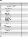
- 21A and 21B are diagrams showing examples of the QMPS. The number at the left end of each row indicates the row number and is attached for convenience of explanation.
- QuantizaionMatrixParameterSet () on the first line in FIG. 21A is a function that expresses the syntax of one QMPS.
- a QMPS ID quantization_matrix_paramter_id
- a generation mode presence flag pred_present_flag
- Each parameter is set for all sizes (for example, 4 ⁇ 4, 8 ⁇ 8, 16 ⁇ 16, and 32 ⁇ 32) for each of intra prediction, inter prediction, and Y, Cb, and Cr ( Lines 4 and 5).
- the generation mode presence flag (pred_present_flag) is read (third line), and when the value is 1, a prediction mode flag (pred_mode) that is flag information indicating the prediction mode is read (the sixth and second lines). 7 lines).
- this prediction mode flag (pred_mode) is 0 (line 8)
- a copy mode syntax for generating a quantization matrix using a previously transmitted quantization matrix is selected (line 9 to 16). line).
- prediction mode flag (pred_mode) is 1 (line 17)
- the syntax of the axis designation mode for setting the basic axis as described above is selected (lines 18 to 50).
- a differential mode flag (dpcm_flag) indicating whether or not the transmission mode is a differential mode is read (line 18), and when the differential mode flag (dpcm_flag) is 1, the syntax of the differential mode is selected (first) 19th line to 40th line).
- Lines 20 to 25 are processes related to the vertical axis
- lines 26 to 34 are processes related to the horizontal axis
- lines 35 to 40 are processes related to the diagonal axis.
- the initial value of the variable nextcoef is set to 0 (line 20).
- a difference value delta_coef between the matrix element currently processed and the matrix element processed immediately before is read (line 22), and the difference value delta_coef is set to the value of the variable nextcoef.
- the value of the variable nextcoef is updated to the value of the matrix element that is the current processing target (line 23).
- the variable coef_vertical [i] indicating each matrix element on the vertical axis is updated to the value of the variable nextcoef (line 24).
- the above processing is performed on all matrix elements on the vertical axis (21st and 25th rows).
- the initial value of the variable nextcoef (the first (eg, the leftmost) matrix element coef_horizontal [0]) of the variable nextcoef is the first (eg, the top) matrix of the vertical axis.
- element coef_vertical [0] (line 26).
- the same identification data (copy_from_vertical) is read (line 27), and the same identification data (copy_from_vertical) is not 0, that is, the interpolation quantization matrix does not have symmetry (line 28).
- the difference value delta_coef between the currently processed matrix element and the matrix element processed immediately before is read (line 30), and the difference value delta_coef is added.
- the value of the variable nextcoef is updated to the value of the matrix element that is currently processed (line 31).
- the variable coef_horizontal [i] indicating each matrix element on the horizontal axis is updated to the value of the variable nextcoef (line 32).
- the oblique axis identification data is 1 and there is an oblique axis
- the same processing as the case of the vertical axis and the horizontal axis is performed for the oblique axis. That is, first, the initial value of the variable nextcoef (the first (eg, the upper left) matrix element coef_diagonal [0] on the diagonal axis is changed to the first (eg, the uppermost) matrix element coef_vertical [0] on the vertical axis. Is set (line 35).
- the difference value delta_coef between the currently processed matrix element and the matrix element processed immediately before is read (line 37), the difference value delta_coef is added, and the value of the variable nextcoef is It is updated to the value of the matrix element that is currently processed (line 38). Then, the variable coef_diagonal [i] indicating each matrix element on the oblique axis is updated to the value of the variable nextcoef (line 39).
- the matrix element (dc) indicating the DC component of the quantization matrix
- the matrix element obtained by extrapolating the horizontal axis horizontal_end
- the matrix element obtained by extrapolating the vertical axis vertical_end
- the diagonal axis Of the matrix elements (diagonal_end) subjected to extrapolation the transmitted one is read (line 42 to line 45). Then, each axis is generated by calculation using these reference matrix elements.
- residual identification data (residual_flag) is read (line 47).
- residual identification data (residual_flag) is 1, that is, when the residual quantization matrix is transmitted (the 48th and 50th lines)
- the residual quantization matrix (residual_matrix (i)) is read ( Line 49).
- the syntax of the residual quantization matrix is shown in the 61st to 80th lines in FIG. 21B.
- the residual quantization matrix also has a difference mode and an operation mode. In the case of the difference mode, the syntaxes of the 63rd to 69th lines are selected, In the case of the calculation mode, the syntax of the 70th to 79th lines is selected.
- Each matrix element of the residual quantization matrix generated as described above is added to each matrix element of the interpolation quantization matrix. Thereby, a quantization matrix is generated.
- residual_flag residual identification data
- prediction mode flag (pred_mode) is 2 (line 51 and line 53)
- the transmitted quantization matrix (qmatrix (i, j)) is read in the same manner as in the past (line 52).
- the generation mode presence flag (pred_present_flag) is not 1 (line 54 and line 56)
- the transmitted quantization matrix (qmatrix (i, j)) is read in the same manner as in the past (line 55).
- the image encoding device 10 and the image decoding device 60 include a transmitter or a receiver in satellite broadcasting, cable broadcasting such as cable TV, distribution on the Internet, and distribution to terminals by cellular communication,
- the present invention can be applied to various electronic devices such as a recording apparatus that records an image on a medium such as an optical disk, a magnetic disk, and a flash memory, or a reproducing apparatus that reproduces an image from the storage medium.
- a recording apparatus that records an image on a medium such as an optical disk, a magnetic disk, and a flash memory
- a reproducing apparatus that reproduces an image from the storage medium.
- FIG. 17 shows an example of a schematic configuration of a television apparatus to which the above-described embodiment is applied.
- the television apparatus 900 includes an antenna 901, a tuner 902, a demultiplexer 903, a decoder 904, a video signal processing unit 905, a display unit 906, an audio signal processing unit 907, a speaker 908, an external interface 909, a control unit 910, a user interface 911, And a bus 912.
- Tuner 902 extracts a signal of a desired channel from a broadcast signal received via antenna 901, and demodulates the extracted signal. Then, the tuner 902 outputs the encoded bit stream obtained by the demodulation to the demultiplexer 903. In other words, the tuner 902 serves as a transmission unit in the television apparatus 900 that receives an encoded stream in which an image is encoded.
- the demultiplexer 903 separates the video stream and audio stream of the viewing target program from the encoded bit stream, and outputs each separated stream to the decoder 904. In addition, the demultiplexer 903 extracts auxiliary data such as EPG (Electronic Program Guide) from the encoded bit stream, and supplies the extracted data to the control unit 910. Note that the demultiplexer 903 may perform descrambling when the encoded bit stream is scrambled.
- EPG Electronic Program Guide
- the decoder 904 decodes the video stream and audio stream input from the demultiplexer 903. Then, the decoder 904 outputs the video data generated by the decoding process to the video signal processing unit 905. In addition, the decoder 904 outputs audio data generated by the decoding process to the audio signal processing unit 907.
- the video signal processing unit 905 reproduces the video data input from the decoder 904 and causes the display unit 906 to display the video.
- the video signal processing unit 905 may cause the display unit 906 to display an application screen supplied via a network.
- the video signal processing unit 905 may perform additional processing such as noise removal on the video data according to the setting.
- the video signal processing unit 905 may generate a GUI (Graphical User Interface) image such as a menu, a button, or a cursor, and superimpose the generated image on the output image.
- GUI Graphic User Interface
- the display unit 906 is driven by a drive signal supplied from the video signal processing unit 905, and displays a video or an image on a video screen of a display device (for example, a liquid crystal display, a plasma display, or an OLED).
- a display device for example, a liquid crystal display, a plasma display, or an OLED.
- the audio signal processing unit 907 performs reproduction processing such as D / A conversion and amplification on the audio data input from the decoder 904, and outputs audio from the speaker 908.
- the audio signal processing unit 907 may perform additional processing such as noise removal on the audio data.
- the external interface 909 is an interface for connecting the television apparatus 900 to an external device or a network.
- a video stream or an audio stream received via the external interface 909 may be decoded by the decoder 904. That is, the external interface 909 also has a role as a transmission unit in the television apparatus 900 that receives an encoded stream in which an image is encoded.
- the control unit 910 has a processor such as a CPU (Central Processing Unit) and a memory such as a RAM (Random Access Memory) and a ROM (Read Only Memory).
- the memory stores a program executed by the CPU, program data, EPG data, data acquired via a network, and the like.
- the program stored in the memory is read and executed by the CPU when the television device 900 is activated, for example.
- the CPU controls the operation of the television device 900 according to an operation signal input from the user interface 911, for example, by executing the program.
- the user interface 911 is connected to the control unit 910.
- the user interface 911 includes, for example, buttons and switches for the user to operate the television device 900, a remote control signal receiving unit, and the like.
- the user interface 911 detects an operation by the user via these components, generates an operation signal, and outputs the generated operation signal to the control unit 910.
- the bus 912 connects the tuner 902, the demultiplexer 903, the decoder 904, the video signal processing unit 905, the audio signal processing unit 907, the external interface 909, and the control unit 910 to each other.
- the decoder 904 has the function of the image decoding apparatus 60 according to the above-described embodiment. Therefore, when the image is decoded by the television apparatus 900, an increase in the amount of codes when the number of quantization matrices increases can be suppressed.
- FIG. 18 shows an example of a schematic configuration of a mobile phone to which the above-described embodiment is applied.
- a mobile phone 920 includes an antenna 921, a communication unit 922, an audio codec 923, a speaker 924, a microphone 925, a camera unit 926, an image processing unit 927, a demultiplexing unit 928, a recording / reproducing unit 929, a display unit 930, a control unit 931, an operation A portion 932 and a bus 933.
- the antenna 921 is connected to the communication unit 922.
- the speaker 924 and the microphone 925 are connected to the audio codec 923.
- the operation unit 932 is connected to the control unit 931.
- the bus 933 connects the communication unit 922, the audio codec 923, the camera unit 926, the image processing unit 927, the demultiplexing unit 928, the recording / reproducing unit 929, the display unit 930, and the control unit 931 to each other.
- the mobile phone 920 has various operation modes including a voice call mode, a data communication mode, a shooting mode, and a videophone mode, and is used for sending and receiving voice signals, sending and receiving e-mail or image data, taking images, and recording data. Perform the action.
- the analog voice signal generated by the microphone 925 is supplied to the voice codec 923.
- the audio codec 923 converts an analog audio signal into audio data, A / D converts the compressed audio data, and compresses it. Then, the audio codec 923 outputs the compressed audio data to the communication unit 922.
- the communication unit 922 encodes and modulates the audio data and generates a transmission signal. Then, the communication unit 922 transmits the generated transmission signal to a base station (not shown) via the antenna 921. In addition, the communication unit 922 amplifies a radio signal received via the antenna 921 and performs frequency conversion to acquire a received signal.
- the communication unit 922 demodulates and decodes the received signal to generate audio data, and outputs the generated audio data to the audio codec 923.
- the audio codec 923 expands the audio data and performs D / A conversion to generate an analog audio signal. Then, the audio codec 923 supplies the generated audio signal to the speaker 924 to output audio.
- the control unit 931 generates character data constituting the e-mail in response to an operation by the user via the operation unit 932.
- the control unit 931 causes the display unit 930 to display characters.
- the control unit 931 generates e-mail data in response to a transmission instruction from the user via the operation unit 932, and outputs the generated e-mail data to the communication unit 922.
- the communication unit 922 encodes and modulates email data and generates a transmission signal. Then, the communication unit 922 transmits the generated transmission signal to a base station (not shown) via the antenna 921.
- the communication unit 922 amplifies a radio signal received via the antenna 921 and performs frequency conversion to acquire a received signal.
- the communication unit 922 demodulates and decodes the received signal to restore the email data, and outputs the restored email data to the control unit 931.
- the control unit 931 displays the content of the electronic mail on the display unit 930 and stores the electronic mail data in the storage medium of the recording / reproducing unit 929.
- the recording / reproducing unit 929 has an arbitrary readable / writable storage medium.
- the storage medium may be a built-in storage medium such as a RAM or a flash memory, or an externally mounted storage medium such as a hard disk, a magnetic disk, a magneto-optical disk, an optical disk, a USB memory, or a memory card. May be.
- the camera unit 926 images a subject to generate image data, and outputs the generated image data to the image processing unit 927.
- the image processing unit 927 encodes the image data input from the camera unit 926 and stores the encoded stream in the storage medium of the storage / playback unit 929.
- the demultiplexing unit 928 multiplexes the video stream encoded by the image processing unit 927 and the audio stream input from the audio codec 923, and the multiplexed stream is the communication unit 922. Output to.
- the communication unit 922 encodes and modulates the stream and generates a transmission signal. Then, the communication unit 922 transmits the generated transmission signal to a base station (not shown) via the antenna 921.
- the communication unit 922 amplifies a radio signal received via the antenna 921 and performs frequency conversion to acquire a received signal.
- These transmission signal and reception signal may include an encoded bit stream.
- the communication unit 922 demodulates and decodes the received signal to restore the stream, and outputs the restored stream to the demultiplexing unit 928.
- the demultiplexing unit 928 separates the video stream and the audio stream from the input stream, and outputs the video stream to the image processing unit 927 and the audio stream to the audio codec 923.
- the image processing unit 927 decodes the video stream and generates video data.
- the video data is supplied to the display unit 930, and a series of images is displayed on the display unit 930.
- the audio codec 923 decompresses the audio stream and performs D / A conversion to generate an analog audio signal. Then, the audio codec 923 supplies the generated audio signal to the speaker 924 to output audio.
- the image processing unit 927 has the functions of the image encoding device 10 and the image decoding device 60 according to the above-described embodiment. Thereby, at the time of encoding and decoding of an image with the mobile phone 920, an increase in the amount of codes when the number of quantization matrices increases can be suppressed.
- FIG. 19 shows an example of a schematic configuration of a recording / reproducing apparatus to which the above-described embodiment is applied.
- the recording / reproducing device 940 encodes audio data and video data of a received broadcast program and records the encoded data on a recording medium.
- the recording / reproducing device 940 may encode audio data and video data acquired from another device and record them on a recording medium, for example.
- the recording / reproducing device 940 reproduces data recorded on the recording medium on a monitor and a speaker, for example, in accordance with a user instruction. At this time, the recording / reproducing device 940 decodes the audio data and the video data.
- the recording / reproducing device 940 includes a tuner 941, an external interface 942, an encoder 943, an HDD (Hard Disk Drive) 944, a disk drive 945, a selector 946, a decoder 947, an OSD (On-Screen Display) 948, a control unit 949, and a user interface. 950.
- Tuner 941 extracts a signal of a desired channel from a broadcast signal received via an antenna (not shown), and demodulates the extracted signal. Then, the tuner 941 outputs the encoded bit stream obtained by the demodulation to the selector 946. That is, the tuner 941 has a role as a transmission unit in the recording / reproducing apparatus 940.
- the external interface 942 is an interface for connecting the recording / reproducing apparatus 940 to an external device or a network.
- the external interface 942 may be, for example, an IEEE 1394 interface, a network interface, a USB interface, or a flash memory interface.
- video data and audio data received via the external interface 942 are input to the encoder 943. That is, the external interface 942 serves as a transmission unit in the recording / reproducing device 940.
- the encoder 943 encodes video data and audio data when the video data and audio data input from the external interface 942 are not encoded. Then, the encoder 943 outputs the encoded bit stream to the selector 946.
- the HDD 944 records an encoded bit stream in which content data such as video and audio is compressed, various programs, and other data on an internal hard disk. Also, the HDD 944 reads out these data from the hard disk when playing back video and audio.
- the disk drive 945 performs recording and reading of data to and from the mounted recording medium.
- the recording medium loaded in the disk drive 945 may be, for example, a DVD disk (DVD-Video, DVD-RAM, DVD-R, DVD-RW, DVD + R, DVD + RW, etc.) or a Blu-ray (registered trademark) disk. .
- the selector 946 selects an encoded bit stream input from the tuner 941 or the encoder 943 when recording video and audio, and outputs the selected encoded bit stream to the HDD 944 or the disk drive 945. In addition, the selector 946 outputs the encoded bit stream input from the HDD 944 or the disk drive 945 to the decoder 947 during video and audio reproduction.
- the decoder 947 decodes the encoded bit stream and generates video data and audio data. Then, the decoder 947 outputs the generated video data to the OSD 948. The decoder 904 outputs the generated audio data to an external speaker.
- the OSD 948 reproduces the video data input from the decoder 947 and displays the video. Further, the OSD 948 may superimpose a GUI image such as a menu, a button, or a cursor on the video to be displayed.
- a GUI image such as a menu, a button, or a cursor
- the control unit 949 includes a processor such as a CPU and memories such as a RAM and a ROM.
- the memory stores a program executed by the CPU, program data, and the like.
- the program stored in the memory is read and executed by the CPU when the recording / reproducing apparatus 940 is activated, for example.
- the CPU controls the operation of the recording / reproducing device 940 according to an operation signal input from the user interface 950, for example, by executing the program.
- the user interface 950 is connected to the control unit 949.
- the user interface 950 includes, for example, buttons and switches for the user to operate the recording / reproducing device 940, a remote control signal receiving unit, and the like.
- the user interface 950 detects an operation by the user via these components, generates an operation signal, and outputs the generated operation signal to the control unit 949.
- the encoder 943 has the function of the image encoding apparatus 10 according to the above-described embodiment.
- the decoder 947 has the function of the image decoding device 60 according to the above-described embodiment.
- FIG. 20 illustrates an example of a schematic configuration of an imaging apparatus to which the above-described embodiment is applied.
- the imaging device 960 images a subject to generate an image, encodes the image data, and records it on a recording medium.
- the imaging device 960 includes an optical block 961, an imaging unit 962, a signal processing unit 963, an image processing unit 964, a display unit 965, an external interface 966, a memory 967, a media drive 968, an OSD 969, a control unit 970, a user interface 971, and a bus. 972.
- the optical block 961 is connected to the imaging unit 962.
- the imaging unit 962 is connected to the signal processing unit 963.
- the display unit 965 is connected to the image processing unit 964.
- the user interface 971 is connected to the control unit 970.
- the bus 972 connects the image processing unit 964, the external interface 966, the memory 967, the media drive 968, the OSD 969, and the control unit 970 to each other.
- the optical block 961 includes a focus lens and a diaphragm mechanism.
- the optical block 961 forms an optical image of the subject on the imaging surface of the imaging unit 962.
- the imaging unit 962 includes an image sensor such as a CCD or a CMOS, and converts an optical image formed on the imaging surface into an image signal as an electrical signal by photoelectric conversion. Then, the imaging unit 962 outputs the image signal to the signal processing unit 963.
- the signal processing unit 963 performs various camera signal processing such as knee correction, gamma correction, and color correction on the image signal input from the imaging unit 962.
- the signal processing unit 963 outputs the image data after the camera signal processing to the image processing unit 964.
- the image processing unit 964 encodes the image data input from the signal processing unit 963 and generates encoded data. Then, the image processing unit 964 outputs the generated encoded data to the external interface 966 or the media drive 968. The image processing unit 964 also decodes encoded data input from the external interface 966 or the media drive 968 to generate image data. Then, the image processing unit 964 outputs the generated image data to the display unit 965. In addition, the image processing unit 964 may display the image by outputting the image data input from the signal processing unit 963 to the display unit 965. Further, the image processing unit 964 may superimpose display data acquired from the OSD 969 on an image output to the display unit 965.
- the OSD 969 generates a GUI image such as a menu, a button, or a cursor, for example, and outputs the generated image to the image processing unit 964.
- the external interface 966 is configured as a USB input / output terminal, for example.
- the external interface 966 connects the imaging device 960 and a printer, for example, when printing an image.
- a drive is connected to the external interface 966 as necessary.
- a removable medium such as a magnetic disk or an optical disk is attached to the drive, and a program read from the removable medium can be installed in the imaging device 960.
- the external interface 966 may be configured as a network interface connected to a network such as a LAN or the Internet. That is, the external interface 966 has a role as a transmission unit in the imaging device 960.
- the recording medium mounted on the media drive 968 may be any readable / writable removable medium such as a magnetic disk, a magneto-optical disk, an optical disk, or a semiconductor memory. Further, a recording medium may be fixedly attached to the media drive 968, and a non-portable storage unit such as an internal hard disk drive or an SSD (Solid State Drive) may be configured.
- a non-portable storage unit such as an internal hard disk drive or an SSD (Solid State Drive) may be configured.
- the control unit 970 includes a processor such as a CPU and memories such as a RAM and a ROM.
- the memory stores a program executed by the CPU, program data, and the like.
- the program stored in the memory is read and executed by the CPU when the imaging device 960 is activated, for example.
- the CPU controls the operation of the imaging device 960 according to an operation signal input from the user interface 971, for example, by executing the program.
- the user interface 971 is connected to the control unit 970.
- the user interface 971 includes, for example, buttons and switches for the user to operate the imaging device 960.
- the user interface 971 detects an operation by the user via these components, generates an operation signal, and outputs the generated operation signal to the control unit 970.
- the image processing unit 964 has the functions of the image encoding device 10 and the image decoding device 60 according to the above-described embodiment. Thereby, at the time of image encoding and decoding by the imaging device 960, an increase in the amount of code when the number of quantization matrices increases can be suppressed.
- the image encoding device 10 and the image decoding device 60 according to an embodiment of the present disclosure have been described using FIGS. 1 to 20.
- the matrix elements to be transmitted are set according to an operation using the reference matrix element as a parameter for the matrix elements included in the quantization matrix corresponding to the transform unit. Since the selected reference matrix element is selected as the reference matrix element and transmitted, an increase in the code amount of the quantization matrix can be suppressed.
- each coefficient of the DC component and the base matrix may be transmitted.
- Each coefficient of the base matrix may be in the difference mode or the calculation mode.
- the encoding side and the decoding side may share a plurality of pattern base matrices in advance, and information indicating which matrix is used may be provided from the encoding side to the decoding side.
- information for generating a quantization matrix is multiplexed with an encoded stream and transmitted, or transmitted as a parameter set from the encoding side to the decoding side.
- the method for transmitting such information is not limited to this example.
- these pieces of information may be transmitted or recorded as separate data associated with the encoded bitstream without being multiplexed into the encoded bitstream.
- the term “associate” means that an image (which may be a part of an image such as a slice or a block) included in the bitstream and information corresponding to the image can be linked at the time of decoding. Means. That is, information may be transmitted on a transmission path different from that of the image (or bit stream).
- the information may be recorded on a recording medium (or another recording area of the same recording medium) different from the image (or bit stream). Furthermore, the information and the image (or the bit stream) may be associated with each other in an arbitrary unit such as a plurality of frames, one frame, or a part of the frame.
- processing is performed in the order of setting / generation of the vertical axis, setting / generation of the horizontal axis, and setting / generation of the diagonal axis, but the order of the above processing is arbitrary (horizontal (Axis ⁇ vertical axis ⁇ diagonal axis, etc.) can be set.
- the reference axis can be selected in consideration of the code amount of the reference axis and the interpolation accuracy of the interpolation matrix.
- the reference axis selection pattern may be other than those described above.
- various patterns are conceivable as shown in a table shown in FIG.
- the reference axis may be only the vertical axis as in the top case of the table shown in FIG. In this case, regardless of the difference mode or the calculation mode, only the information about the vertical axis is transmitted.
- the horizontal axis is the same as the vertical axis, and information regarding the oblique axis is not transmitted.
- the diagonal axis may be the same as the vertical axis, or may be generated by interpolation processing in the same manner as the matrix elements other than the axis.
- the reference axis may be only the horizontal axis. In this case, it is the same as the top case described above except that the vertical axis and the horizontal axis are interchanged.
- the reference axis may be a vertical axis and an oblique axis. In this case, information regarding the vertical axis and the oblique axis is transmitted regardless of the difference mode or the calculation mode.
- the horizontal axis is the same as the vertical axis.
- the reference axis may be a horizontal axis and an oblique axis. This is the same as the third case from above except that the vertical axis and the horizontal axis are interchanged.
- the amount of code increases by the amount of information on the oblique axis, but the prediction accuracy is easily improved.
- the reference axis may be the vertical axis, the horizontal axis, and the oblique axis.
- the reference axis may be the vertical axis, the horizontal axis, and the oblique axis.
- information on all of the vertical axis, the horizontal axis, and the oblique axis is transmitted.
- the code amount is increased as compared with the other cases described above, but it is easy to improve the prediction accuracy even when the quantization matrix is more complicated.
- patterns other than those shown in FIG. 22 may be used.
- processing is performed according to the setting / generation of three axes (setting / generation of the vertical axis, setting / generation of the horizontal axis, setting / generation of the oblique axis), but more than three axes.
- the reference axis For example, it is possible to set and generate three vertical axes, horizontal axes, and diagonal axes (9 axes in total) as reference axes and use the same method.
- an 8 ⁇ 8 quantization matrix is described as an example, but a similar method can be used for 16 ⁇ 16 and 32 ⁇ 32 quantization matrices. in this case.
- the difference from the previous matrix element is used in the reference axis, but the difference of the matrix element can be used between different reference axes.
- the difference value ⁇ of the DC component reference matrix element (rs)
- the difference value ⁇ of the DC component is an arbitrary value and a reference It is good also as a difference value of a matrix element (rs).
- the DC component difference value ⁇ may be set to “8” and the difference value of the reference matrix element (rs).
- the code amount can be reduced by making the difference value as small as possible.
- the transmission mode selection method is arbitrary, and may be determined based on a user or application instruction, or may be determined by obtaining a cost function value and determining the magnitude of the value. .
- the vertical axis generation unit 213 to the diagonal axis generation unit 215 restore each reference matrix element (re, ce, xe) from the difference value and the matrix element for the direct correction, Good. In this way, the code amount of each reference matrix element (re, ce, xe) can be reduced.
- interpolation method of the matrix elements other than the axes is arbitrary and may be other than the above.
- interpolation may be performed using two-axis matrix elements (for example, the vertical axis and the diagonal axis, and the horizontal axis and the diagonal axis) in the same column or the same row.
- the pattern of the arithmetic expression is smaller than the above-described example, and development is facilitated.
- the denominator of division is limited to 2, so the processing load may be reduced compared to this case.
- matrix elements other than the axis may be interpolated from the oblique axis.
- the upper left matrix element that is, the direct current (DC) component
- the oblique axis is calculated by linear calculation using these two points (B in FIG. 24).
- each calculated matrix element on the oblique axis is copied (copied) in a direction perpendicular to the oblique axis (an oblique direction on the upper right and lower left), for example, as shown in FIG. In this way, each matrix element is interpolated, and an interpolated quantization matrix is generated as shown in FIG.
- the matrix element is a quantization matrix having a high correlation in the diagonal direction perpendicular to the diagonal axis, such as the default matrix of AVC, in the method of interpolating from the above-described two or three axes using a weighted average or the like, Prediction accuracy may be difficult to improve.
- the prediction accuracy is improved by performing the interpolation process by duplicating the matrix element in the oblique direction perpendicular to the oblique axis, and the encoding efficiency is increased. Can be improved.
- this diagonal axis may be generated by the differential mode.
- each difference value between adjacent matrix elements on the oblique axis is transmitted.
- the method of interpolating other matrix elements from the obtained oblique axis is the same as in the above-described calculation mode.
- each matrix element on the oblique axis may be transmitted without being compressed.
- the matrix elements of the vertical axis and the horizontal axis are replicated in the diagonal direction perpendicular to the diagonal axis, as in the case of the diagonal axis. May be.
- the upper left matrix element that is, the direct current (DC) component
- the upper right matrix element and the lower right matrix element are transmitted as reference matrix elements. .
- each matrix element on the vertical axis and each matrix element on the horizontal axis are copied (copied) in a direction perpendicular to the oblique axis (an oblique direction in the upper right and lower left). .
- each matrix element is interpolated, and an interpolated quantization matrix is generated as shown in FIG.
- the prediction accuracy can be improved and the coding efficiency can be improved for a quantization matrix whose matrix elements are highly correlated in an oblique direction perpendicular to the oblique axis.
- the two axes (the top row and the rightmost column) may be generated by the difference mode.
- the method of interpolating other matrix elements from the obtained two axes is the same as in the above-described calculation mode.
- the biaxial matrix elements may be transmitted without being compressed.
- the matrix elements other than the axes may be interpolated by duplicating the matrix elements in the bottom row and the leftmost column in an oblique direction perpendicular to the oblique axis. That is, instead of the top row and the rightmost column, the bottom row and the leftmost column may be two axes. In this case as well, the calculation method is basically the same as when the top row and the rightmost column are two axes.
- the matrix elements at the four corners of the quantization matrix may be transmitted, the four sides of the quantization matrix may be calculated from the four points as axes, and the other matrix elements may be interpolated from the four axes.
- interpolation calculation can be performed in an oblique direction perpendicular to the oblique axis, but in this case, each weighted average is performed by performing a weighted average according to the position using the opposing two-axis matrix elements. Perform matrix element interpolation. By doing in this way, the prediction precision to a more complicated quantization matrix can be improved rather than the case where each matrix element on an axis
- the method of transmitting only two points and performing the interpolation processing from the oblique axis obtained in the calculation mode described above can reduce the transmission amount most.
- the method of transmitting the diagonal axis or the vertical axis and the horizontal axis without compression can reduce the amount of interpolation processing most.
- the method of transmitting the four corners (four points) of the quantization matrix can improve the prediction accuracy for the most complex quantization coefficient.
- the calculation used for the reference axis may be, for example, a quadratic or higher expression.
- the entire quantization matrix may be predicted (planar fitting) with an n-order equation. In this case, the calculation amount may increase compared to the other cases described above, but the prediction accuracy can be easily improved and the code amount can be reduced.
- the difference mode and the calculation mode may be used together for one quantization matrix.
- the vertical axis or the horizontal axis may be the calculation mode
- the diagonal axis may be the difference mode.
- each matrix element of the residual quantization matrix may be quantized and transmitted.
- Each matrix element quantized and transmitted is dequantized on the decoding side.
- an error occurs in the residual quantization matrix due to such quantization.
- a matrix element having a small value such as “1” is highly likely to have a small influence even if omitted. Therefore, when such an error due to quantization is allowed, the code amount of the residual quantization matrix can be reduced by quantizing each matrix element.
- orthogonal transform may be performed before quantization.
- the orthogonal transform unit 120 and the quantizer 130 are used on the encoding side, and the inverse quantization unit 240 and the inverse orthogonal transform unit 250 are used on the decoding side. Also good. In this way, the existing processing unit can be reused and development is easy.
- the reference axis is lossless and no prediction error occurs. Therefore, since all matrix elements of the reference axis are 0 in the residual quantization matrix, transmission of the matrix elements of the reference axis may be omitted. That is, for example, when the residual processing unit 157 has the vertical axis, the horizontal axis, and the diagonal axis as shown in FIG. 23A, the residual quantization matrix other than that indicated by the diagonal lines Only the matrix elements may be generated, and the parameter generation unit 156 may transmit them.
- the reference axis is set to two axes or one axis, it is necessary to transmit the matrix elements of the parts that are not set as the reference axes. In this way, the code amount of the residual quantization matrix can be reduced.
- the quantization matrix often has symmetry (substantially symmetric matrix). Therefore, only one of the line-symmetric matrix elements may be transmitted as in the example shown in FIG.
- the residual processing unit 157 generates only the diagonal component of the residual quantization matrix and the matrix element above (or to the right of) the diagonal component as indicated by the hatched portion shown in FIG.
- the parameter generation unit 156 transmits it as a residual quantization matrix.
- the residual processing unit 218 obtains the residual quantization matrix (only the diagonal component and the portion above the diagonal component) and uses it to obtain a value below the diagonal component of the residual quantization matrix ( Alternatively, the left part is generated. That is, the residual processing unit 218 copies the matrix element at the position corresponding to the line object in the portion above the diagonal component of the residual quantization matrix, thereby lowering the diagonal component of the residual quantization matrix.
- the part is restored (that is, each matrix element is folded and copied around the diagonal component of the residual quantization matrix). By doing so, since the matrix elements to be transmitted are reduced, the amount of codes can be reduced accordingly.
- transmission of the matrix element of the reference axis may be omitted as a matter of course. Further, the difference between the matrix element located below the diagonal component generated by folding and copying the matrix element located above the diagonal component as described above and the matrix element of the actual quantization matrix is further calculated. You may make it transmit. Of course, the transmission portion may be a portion below the diagonal component and the diagonal component, and the portion above the diagonal component may be restored.
- the quantization matrix may be quantized. This method is suitable for a lower bit rate in which the quantization matrix overhead (ratio of code amount) becomes larger. For example, as shown in FIG. 26, the quantization matrix is divided into a plurality of regions and is performed for each region.
- the 8 ⁇ 8 quantization matrix is divided into four regions in the upper right and lower left diagonal directions (region 0 to region 3).
- each matrix element of the quantization matrix is highly correlated in the diagonal direction in the upper right and lower left.
- the upper left matrix element of the quantization matrix corresponds to a lower frequency component of the coefficient data
- the lower right matrix element corresponds to a higher frequency component of the coefficient data.
- the quantization matrix is generally often so-called zigzag scanned. Therefore, it is preferable to divide the quantization matrix in the diagonal direction in the upper right and lower left as in the example shown in FIG.
- Quantization for each region is performed at the set quantization scale.
- This quantization scale can be set independently for each region. Examples of syntax are shown in FIGS. 28A to 28D. In FIG. 28A to FIG. 28D, the number on the left end is a line number given for convenience of explanation, and is not an actual syntax.
- the quantization scale for each region is shown in the seventh to tenth rows in FIG. 28A (Qscale0, Qscale1, Qscale2, Qscale3).
- the region 0 indicated by “0” in FIG. 26 is a low-frequency region including a DC component, it is generally desirable to improve reproducibility (to make it as close to lossless as possible), and the quantization scale (Qscale0) Should be smaller.
- the region 3 indicated by “3” in FIG. 26 is a high-frequency region, so even if the error is large, the influence is small. Therefore, in general, it is desirable that the code amount is small, and therefore it is desirable that the quantization scale (Qscale3) of region 3 is large.
- each region is generally required to be different depending on the frequency band, by making it possible to set the quantization scale for each region as described above, The degree of freedom of setting is improved, and more preferable setting is possible.
- the method of dividing the quantization matrix is arbitrary and may be other than the diagonal direction in the upper right and lower left. For example, it may be divided into rectangles of a predetermined size. Also, the size of each region is arbitrary and may be different from each other. Of course, the number of divisions is also arbitrary. Furthermore, the number of divisions (area size) may be variable according to the size of the quantization matrix.
- the residual processing unit 157 performs run-length encoding on the residual quantization matrix.
- the residual processing unit 157 includes a plurality of VLC tables (VLC table). It may be possible to explicitly select (preset) a table having the smallest code amount from among the tables.
- the residual processing unit 157 may explicitly select (preset) a table having the smallest code amount from the plurality of VLC tables.
- the level is a small number such as 1 or 2, and VLC is also optimized. Therefore, even if the optimum VLC table is switched, transmission of the table identification number for each DCT does not lead to a gain because the overhead is large.
- tables may be selected independently of each other. For example, a large table may be selected for the run (RUN) and a small table may be selected for the data (DATA).
- the table (vlc_table_run) selected for the run is shown in the 63rd and 73rd lines in FIG. 28B and the 96th line in FIG. 28C.
- the 61st and 71st lines and the 87th and 95th lines of FIG. 28C show the tables selected for the data.
- the quantization matrix has been described as an example. However, in addition to the quantization matrix, a similar method can be applied to a matrix including matrix elements as long as the matrix is used when encoding / decoding an image. Can be applied.
- a CPU (Central Processing Unit) 1201 of the personal computer 1200 has various types according to a program stored in a ROM (Read Only Memory) 1202 or a program loaded from a storage unit 1213 to a RAM (Random Access Memory) 1203. Execute the process.
- the RAM 1203 also appropriately stores data necessary for the CPU 1201 to execute various processes.
- the CPU 1201, the ROM 1202, and the RAM 1203 are connected to each other via a bus 1204.
- An input / output interface 1210 is also connected to the bus 1204.
- the input / output interface 1210 includes an input unit 1211 including a keyboard and a mouse, a display such as a CRT (Cathode Ray Tube) display and an LCD (Liquid Crystal Display), an output unit 1212 including a speaker, a flash memory SSD (Solid, etc.).
- the communication unit 1214 performs communication processing via a network including the Internet.
- a drive 1215 is also connected to the input / output interface 1210 as necessary, and a removable medium 1221 such as a magnetic disk, an optical disk, a magneto-optical disk, or a semiconductor memory is appropriately attached, and a computer program read from them is loaded. It is installed in the storage unit 1213 as necessary.
- a program constituting the software is installed from a network or a recording medium.
- the recording medium is distributed to distribute the program to the user separately from the apparatus main body, and includes a magnetic disk (including a flexible disk), an optical disk (including a flexible disk) It is only composed of removable media 1221 consisting of CD-ROM (compact disc-read only memory), DVD (including digital versatile disc), magneto-optical disc (including MD (mini disc)), or semiconductor memory. Rather, it is composed of a ROM 1202 in which a program is recorded and a hard disk included in the storage unit 1213 which is distributed to the user in a state of being incorporated in the apparatus main body in advance.
- the program executed by the computer may be a program that is processed in time series in the order described in this specification, or in parallel or at a necessary timing such as when a call is made. It may be a program for processing.
- the step of describing the program recorded on the recording medium is not limited to the processing performed in chronological order according to the described order, but may be performed in parallel or It also includes processes that are executed individually.
- system represents the entire apparatus composed of a plurality of devices (apparatuses).
Abstract
La présente invention porte sur un dispositif et un procédé de traitement d'image qui sont aptes à supprimer l'augmentation de la quantité de codes d'une matrice de quantification. Une unité de réglage d'axe (151) règle des axes de référence comprenant des éléments de matrice à transmettre, conformément au type d'une matrice de quantification. Pour un axe vertical réglé par l'unité de réglage d'axe (151), des unités allant d'une unité de réglage d'axe vertical (152) à une unité de réglage d'axe diagonal (154) sélectionnent chacune, à titre d'élément de matrice de référence, un élément de matrice de quantification à transmettre, conformément à un mode dans lequel l'élément de matrice de quantification doit être transmis. Une unité de traitement d'interpolation (155) effectue un traitement d'interpolation et règle une matrice de quantification interpolée. Une unité de traitement de résidu (157) règle une matrice de quantification résiduelle. Une unité de génération de paramètres (156) transmet, à titre de paramètres, les éléments de matrice de référence réglés par les unités allant de l'unité de réglage d'axe vertical (152) à l'unité de réglage d'axe diagonal (154), les différences entre éléments de matrice, et des données générées par l'unité de traitement de résidu. Cette invention est applicable, par exemple, à un dispositif de traitement d'image.
Applications Claiming Priority (6)
| Application Number | Priority Date | Filing Date | Title |
|---|---|---|---|
| JP2011019333 | 2011-01-31 | ||
| JP2011-019333 | 2011-01-31 | ||
| JP2011033689 | 2011-02-18 | ||
| JP2011-033689 | 2011-02-18 | ||
| JP2011-047798 | 2011-03-04 | ||
| JP2011047798A JP2012186617A (ja) | 2011-01-31 | 2011-03-04 | 画像処理装置および方法 |
Publications (1)
| Publication Number | Publication Date |
|---|---|
| WO2012105360A1 true WO2012105360A1 (fr) | 2012-08-09 |
Family
ID=46602579
Family Applications (1)
| Application Number | Title | Priority Date | Filing Date |
|---|---|---|---|
| PCT/JP2012/051381 WO2012105360A1 (fr) | 2011-01-31 | 2012-01-24 | Dispositif et procédé de traitement d'image |
Country Status (2)
| Country | Link |
|---|---|
| JP (1) | JP2012186617A (fr) |
| WO (1) | WO2012105360A1 (fr) |
Cited By (2)
| Publication number | Priority date | Publication date | Assignee | Title |
|---|---|---|---|---|
| JP2014135686A (ja) * | 2013-01-11 | 2014-07-24 | Ntt Electornics Corp | 動画像符号化装置 |
| US9948929B2 (en) | 2012-04-26 | 2018-04-17 | Sony Corporation | Quantization for different color sampling schemes |
Families Citing this family (1)
| Publication number | Priority date | Publication date | Assignee | Title |
|---|---|---|---|---|
| JP7090490B2 (ja) * | 2018-06-28 | 2022-06-24 | キヤノン株式会社 | 画像符号化装置、画像復号装置、画像符号化方法、画像復号方法 |
Citations (3)
| Publication number | Priority date | Publication date | Assignee | Title |
|---|---|---|---|---|
| JPH06284412A (ja) * | 1993-03-26 | 1994-10-07 | Sony Corp | 画像信号符号化方法および画像信号符号化装置、画像信号復号化方法および画像信号復号化装置、ならびに画像信号記録媒体 |
| JPH1188880A (ja) * | 1997-02-08 | 1999-03-30 | Matsushita Electric Ind Co Ltd | 静止画および動画に対する量子化マトリックス |
| WO2005072312A2 (fr) * | 2004-01-20 | 2005-08-11 | Matsushita Electric Industrial Co., Ltd. | Procede de codage d'image, procede de decodage d'image, appareil de codage d'image, appareil de decodage d'image, et programme correspondant |
-
2011
- 2011-03-04 JP JP2011047798A patent/JP2012186617A/ja not_active Withdrawn
-
2012
- 2012-01-24 WO PCT/JP2012/051381 patent/WO2012105360A1/fr active Application Filing
Patent Citations (3)
| Publication number | Priority date | Publication date | Assignee | Title |
|---|---|---|---|---|
| JPH06284412A (ja) * | 1993-03-26 | 1994-10-07 | Sony Corp | 画像信号符号化方法および画像信号符号化装置、画像信号復号化方法および画像信号復号化装置、ならびに画像信号記録媒体 |
| JPH1188880A (ja) * | 1997-02-08 | 1999-03-30 | Matsushita Electric Ind Co Ltd | 静止画および動画に対する量子化マトリックス |
| WO2005072312A2 (fr) * | 2004-01-20 | 2005-08-11 | Matsushita Electric Industrial Co., Ltd. | Procede de codage d'image, procede de decodage d'image, appareil de codage d'image, appareil de decodage d'image, et programme correspondant |
Non-Patent Citations (1)
| Title |
|---|
| AKIYUKI TANIZAWA ET AL.: "Adaptive Quantization Matrix Selection on KTA Software, ITU - Telecommunications Standardization Sector STUDY GROUP 16 Question 6 Video Coding Experts Group (VCEG)", VCEG-AD06, 30TH MEETING, October 2006 (2006-10-01), HANGZHOU, CHINA, pages 1 - 5 * |
Cited By (4)
| Publication number | Priority date | Publication date | Assignee | Title |
|---|---|---|---|---|
| US9948929B2 (en) | 2012-04-26 | 2018-04-17 | Sony Corporation | Quantization for different color sampling schemes |
| US10291909B2 (en) | 2012-04-26 | 2019-05-14 | Sony Corporation | Quantization for different color sampling schemes |
| US10616572B2 (en) | 2012-04-26 | 2020-04-07 | Sony Corporation | Quantization for different color sampling schemes |
| JP2014135686A (ja) * | 2013-01-11 | 2014-07-24 | Ntt Electornics Corp | 動画像符号化装置 |
Also Published As
| Publication number | Publication date |
|---|---|
| JP2012186617A (ja) | 2012-09-27 |
Similar Documents
| Publication | Publication Date | Title |
|---|---|---|
| US11825089B2 (en) | Image processing device and image processing method | |
| US10499057B2 (en) | Image processing device and image processing method | |
| WO2014050731A1 (fr) | Dispositif et procédé de traitement d'image | |
| WO2013108688A1 (fr) | Dispositif de traitement d'image et procédé | |
| WO2012105360A1 (fr) | Dispositif et procédé de traitement d'image | |
| AU2018206825B2 (en) | Image processing device and image processing method | |
| AU2015202011B2 (en) | Image Processing Device and Image Processing Method |
Legal Events
| Date | Code | Title | Description |
|---|---|---|---|
| 121 | Ep: the epo has been informed by wipo that ep was designated in this application |
Ref document number: 12742460 Country of ref document: EP Kind code of ref document: A1 |
|
| NENP | Non-entry into the national phase |
Ref country code: DE |
|
| 122 | Ep: pct application non-entry in european phase |
Ref document number: 12742460 Country of ref document: EP Kind code of ref document: A1 |