WO2012105360A1 - Image processing device and method - Google Patents
Image processing device and method Download PDFInfo
- Publication number
- WO2012105360A1 WO2012105360A1 PCT/JP2012/051381 JP2012051381W WO2012105360A1 WO 2012105360 A1 WO2012105360 A1 WO 2012105360A1 JP 2012051381 W JP2012051381 W JP 2012051381W WO 2012105360 A1 WO2012105360 A1 WO 2012105360A1
- Authority
- WO
- WIPO (PCT)
- Prior art keywords
- matrix
- matrix element
- unit
- quantization
- axis
- Prior art date
Links
Images


Classifications
-
- H—ELECTRICITY
- H04—ELECTRIC COMMUNICATION TECHNIQUE
- H04N—PICTORIAL COMMUNICATION, e.g. TELEVISION
- H04N19/00—Methods or arrangements for coding, decoding, compressing or decompressing digital video signals
- H04N19/10—Methods or arrangements for coding, decoding, compressing or decompressing digital video signals using adaptive coding
- H04N19/102—Methods or arrangements for coding, decoding, compressing or decompressing digital video signals using adaptive coding characterised by the element, parameter or selection affected or controlled by the adaptive coding
- H04N19/124—Quantisation
- H04N19/126—Details of normalisation or weighting functions, e.g. normalisation matrices or variable uniform quantisers
-
- H—ELECTRICITY
- H04—ELECTRIC COMMUNICATION TECHNIQUE
- H04N—PICTORIAL COMMUNICATION, e.g. TELEVISION
- H04N19/00—Methods or arrangements for coding, decoding, compressing or decompressing digital video signals
- H04N19/46—Embedding additional information in the video signal during the compression process
- H04N19/463—Embedding additional information in the video signal during the compression process by compressing encoding parameters before transmission
Definitions
- the present disclosure relates to an image processing apparatus and method.
- MPEG-2 Motion Picture Experts Group 2
- MPEG-2 compression noise This is noise generated by performing large quantization on high frequencies. The frequency component of noise is very high.
- a quantization matrix that makes a high frequency a large quantization value when recompressing is used.
- interlaced signals are used.
- the interlace signal has a high correlation in the horizontal direction but has a low correlation in the vertical direction because interlaced scanning is performed.
- the residual signal at the time of compression tends to have a large residual coefficient in the vertical direction after DCT (Discrete Cosine Transform).
- DCT Discrete Cosine Transform
- H. is one of the standard specifications for video coding.
- H.264 / AVC Advanced Video Video Coding
- different quantization steps can be used for each component of the orthogonal transform coefficient when quantizing image data in a profile higher than High Profile.
- the quantization step for each component of the orthogonal transform coefficient can be set based on a quantization matrix (also referred to as a scaling list) defined with a size equivalent to the unit of the orthogonal transform and a reference step value.
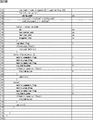
- FIG. 4 shows default values (default values) of four types of quantization matrices defined in advance in H.264 / AVC.
- the matrix SL01 is the default value of the quantization matrix.
- the matrix SL02 is the default value of the quantization matrix.
- the matrix SL03 is a default value of the quantization matrix.
- the matrix SL04 is the default value of the quantization matrix.
- the user can specify a unique quantization matrix different from the default value shown in FIG. 30 in the sequence parameter set or the picture parameter set. When the quantization matrix is not used, the quantization step used in the quantization is the same value for all components.
- HEVC High Efficiency Video Coding
- CU Coding Unit
- SCU Small Cell Coding Unit
- one coding unit may be divided into one or more orthogonal transform units, that is, one or more transform units (TU).
- TU transform units
- any of 4 ⁇ 4, 8 ⁇ 8, 16 ⁇ 16, and 32 ⁇ 32 can be used. Accordingly, a quantization matrix can also be specified for each of these transform unit candidate sizes.
- H. In H.264 / AVC only one quantization matrix can be specified for the size of one transform unit in one picture.
- multiple quantization matrix candidates are specified for the size of one transform unit in one picture, and the quantization matrix is selected adaptively for each block from the viewpoint of RD (Rate-Distortion) optimization.
- RD Rate-Distortion
- JCTVC-B205 “Test Model Consideration”, Joint Collaborative Team on Video Coding (JCT-VC) of ITU-T SG16 WP3 and ISO / IEC JTC1 / SC29 / WG11 2nd Meeting: Geneva, CH, 21-28 July, 2010
- VCEG-AD06 "Adaptive Quantization Matrix Selection on KTA Software”
- the size of the transform unit increases, the size of the corresponding quantization matrix also increases and the amount of code of the transmitted quantization matrix also increases. Furthermore, as the size of the transform unit increases, the overhead increases, and switching the quantization matrix may cause a problem in terms of compression efficiency.
- the present disclosure has been proposed in view of such a situation, and an object thereof is to suppress an increase in the code amount of a quantization matrix.
- One aspect of the present disclosure is directed to a matrix element included in a quantization matrix corresponding to a transform unit, and a selection unit that selects a matrix element to be transmitted as a reference matrix element according to an operation using the reference matrix element as a parameter.
- the image processing apparatus includes a transmission unit that transmits the reference matrix element selected by the selection unit.
- the image processing apparatus can typically be realized as an image encoding apparatus that encodes an image.
- One aspect of the present disclosure is also directed to selecting a matrix element to be transmitted as a reference matrix element according to an operation using the reference matrix element as a parameter for a matrix element included in a quantization matrix corresponding to a transform unit.
- An image processing method including a step and a transmission step of transmitting the reference matrix element selected in the selection step.
- Another aspect of the present disclosure includes: a receiving unit that receives a reference matrix element selected according to an operation using a matrix element as a parameter to which a matrix element included in a quantization matrix corresponding to a transform unit is transmitted; and a reference matrix element
- the calculation unit that calculates the matrix element included in the quantization matrix by applying the reference matrix element received by the receiving unit to the calculation using the parameter as the parameter, the reference matrix element received by the receiving unit, and the calculation unit
- an interpolation quantization matrix generation unit that generates an interpolation quantization matrix including the interpolated interpolation matrix elements by performing an interpolation process on the matrix elements calculated by the above.
- the image processing apparatus can typically be realized as an image decoding apparatus that encodes an image.
- Another aspect of the present disclosure also includes a receiving step of receiving a reference matrix element selected according to an operation having a matrix element as a parameter to which a matrix element included in a quantization matrix corresponding to a transform unit is transmitted; A calculation step of calculating a matrix element included in the quantization matrix by applying the reference matrix element received in the reception step to an operation using the matrix element as a parameter, and the reference matrix element received in the reception step and the calculation And an interpolation quantization matrix generation step of generating an interpolation quantization matrix including the interpolated interpolation matrix elements by performing an interpolation process on the matrix elements calculated by the unit.
- an increase in the code amount of the quantization matrix can be suppressed.
- FIG. 26 is a block diagram illustrating a main configuration example of a personal computer.
- H. 2 is an explanatory diagram illustrating a quantization matrix defined in H.264 / AVC.
- lossless means that the decoding side can generate the desired quantization matrix coefficients (quantization matrix coefficients corresponding to the information supplied by the encoding side) on the encoding side. ing.
- this “lossless” indicates that, in many cases, the same coefficient as that of the quantization matrix used on the encoding side can be generated on the decoding side. The coefficients of the quantization matrix do not have to match the coefficients generated on the decoding side.
- the matrix elements included in the reference axis are calculated on the decoding side using an operation using the matrix elements (reference matrix elements) transmitted to the decoding side as parameters.
- the matrix elements not included in the reference axis are calculated on the decoding side by interpolation processing.
- the encoding side may transmit only the reference matrix element or may further transmit the difference between the reference matrix element and the matrix element. This greatly contributes to the reduction of the code amount of the quantization matrix.
- the quantization matrix is set to have symmetry or to be set to have asymmetry due to interlace progressive.
- the reference axis it is desirable to set the reference axis according to the characteristics (symmetry / asymmetricity) of the quantization matrix. For example, in progressive, the reference matrix element (and the difference) of one of the vertical axis and the horizontal axis is set and transmitted (the axis is copied on the decoding side). In interlace, both the vertical axis and the horizontal axis are set and transmitted.
- the distribution of the prediction residual after DCT has characteristics due to interlace / progressive and intra macroblock / intermacroblock.
- A Progressive and Intra Macroblock: The higher the frequency, the smaller the value, and the distribution in the vertical direction and the distribution in the horizontal direction are substantially symmetrical.
- B Progressive and intermacroblock: The higher the frequency, the smaller the value, but the slope is gentler than that of the intra macroblock, and the distribution in the vertical direction and the distribution in the horizontal direction are substantially symmetrical.
- C Interlace, Intra macroblock: The higher the frequency, the smaller the value, and the distribution is concentrated in the vertical direction. The distribution in the vertical direction and the distribution in the horizontal direction are asymmetric.
- Interlace and inter macroblock The higher the frequency, the smaller the value, but the slope is gentler than that of the intra macroblock, the distribution is concentrated in the vertical direction, and the vertical distribution and the horizontal distribution are asymmetric. (Slope of distribution, bias of coefficient distribution in the vertical direction), the diagonal axis is set and transmitted, the matrix elements included in the diagonal axis are generated losslessly, and the vertical, horizontal, and diagonal axes are used.
- the interpolation accuracy becomes higher when the interpolation processing is performed (the increase in code amount due to the setting and transmission of the oblique axis is slight). Therefore, it is a very important factor to be able to set and transmit an oblique axis.
- the quantization row example is a square matrix, processing symmetry, and the like, it is preferable to set an oblique axis at an equal angle between the vertical axis and the horizontal axis.
- the main points are: Introducing the concept of a reference axis when transmitting a quantization matrix.
- three vertical axes, the horizontal axis, and the diagonal axis should be introduced.
- an operation using the reference matrix element as a parameter (difference mode / operation mode) is introduced.
- a matrix element included in the reference axis is generated according to an operation using the reference matrix element as a parameter, and a matrix element not included in the reference axis is generated by an interpolation process using the matrix element included in the reference axis. Setting and transmitting a residual quantization matrix that is a difference between the quantization matrix and the generated interpolated quantization matrix.
- FIG. 1 is a block diagram illustrating an exemplary configuration of an image encoding device 10 according to an embodiment of the present disclosure.
- an image encoding device 10 includes an analog / digital (A / D) conversion unit 11 (A / D), a rearrangement buffer 12, a subtraction unit 13, an orthogonal transform / quantization unit 14, a lossless encoding.
- Unit 16 accumulation buffer 17, rate control unit 18, inverse quantization unit 21, inverse orthogonal transform unit 22, addition unit 23, deblock filter 24, frame memory 25, selector 26, intra prediction unit 30, motion search unit 40, And a mode selection unit 50.
- the A / D converter 11 converts an image signal input in an analog format into image data in a digital format, and outputs a series of digital image data to the rearrangement buffer 12.
- the rearrangement buffer 12 rearranges the images included in the series of image data input from the A / D conversion unit 11.
- the rearrangement buffer 12 rearranges the images according to the GOP (Group of Pictures) structure related to the encoding process, and then outputs the rearranged image data to the subtraction unit 13, the intra prediction unit 30, and the motion search unit 40. To do.
- GOP Group of Pictures
- the subtraction unit 13 is supplied with image data input from the rearrangement buffer 12 and predicted image data selected by the mode selection unit 50 described later.
- the subtraction unit 13 calculates prediction error data that is a difference between the image data input from the rearrangement buffer 12 and the prediction image data input from the mode selection unit 50, and orthogonally transforms and quantizes the calculated prediction error data.
- the orthogonal transform / quantization unit 14 performs orthogonal transform and quantization on the prediction error data input from the subtraction unit 13, and converts the quantized transform coefficient data (hereinafter referred to as quantized data) into the lossless encoding unit 16 and The result is output to the inverse quantization unit 21.
- the bit rate of the quantized data output from the orthogonal transform / quantization unit 14 is controlled based on the rate control signal from the rate control unit 18. The detailed configuration of the orthogonal transform / quantization unit 14 will be further described later.
- the lossless encoding unit 16 includes quantized data input from the orthogonal transform / quantization unit 14, information for generating a quantization matrix on the decoding side, and intra prediction or interface selected by the mode selection unit 50.
- Information about the prediction is supplied.
- the information regarding intra prediction may include, for example, prediction mode information indicating an optimal intra prediction mode for each block.
- the information regarding inter prediction may include, for example, prediction mode information for motion vector prediction for each block, differential motion vector information, reference image information, and the like.
- the lossless encoding unit 16 generates an encoded stream by performing lossless encoding processing on the quantized data.
- the lossless encoding by the lossless encoding unit 16 may be variable length encoding or arithmetic encoding, for example.
- the lossless encoding unit 16 multiplexes information for generating a quantization matrix, which will be described in detail later, in the header of the encoded stream (for example, a sequence parameter set and a picture parameter set). Further, the lossless encoding unit 16 multiplexes the information related to intra prediction or information related to inter prediction described above in the header of the encoded stream. Then, the lossless encoding unit 16 outputs the generated encoded stream to the accumulation buffer 17.
- the accumulation buffer 17 temporarily accumulates the encoded stream input from the lossless encoding unit 16 using a storage medium such as a semiconductor memory.
- the accumulation buffer 17 outputs the accumulated encoded stream at a rate corresponding to the bandwidth of the transmission path (or the output line from the image encoding device 10).
- the rate control unit 18 monitors the free capacity of the accumulation buffer 17. Then, the rate control unit 18 generates a rate control signal according to the free capacity of the accumulation buffer 17 and outputs the generated rate control signal to the orthogonal transform / quantization unit 14. For example, the rate control unit 18 generates a rate control signal for reducing the bit rate of the quantized data when the free capacity of the storage buffer 17 is small. For example, when the free capacity of the accumulation buffer 17 is sufficiently large, the rate control unit 18 generates a rate control signal for increasing the bit rate of the quantized data.
- the inverse quantization unit 21 performs an inverse quantization process on the quantized data input from the orthogonal transform / quantization unit 14. Then, the inverse quantization unit 21 outputs transform coefficient data acquired by the inverse quantization process to the inverse orthogonal transform unit 22.
- the inverse orthogonal transform unit 22 restores the prediction error data by performing an inverse orthogonal transform process on the transform coefficient data input from the inverse quantization unit 21. Then, the inverse orthogonal transform unit 22 outputs the restored prediction error data to the addition unit 23.
- the addition unit 23 generates decoded image data by adding the restored prediction error data input from the inverse orthogonal transform unit 22 and the predicted image data input from the mode selection unit 50. Then, the addition unit 23 outputs the generated decoded image data to the deblock filter 24 and the frame memory 25.
- the deblocking filter 24 performs a filtering process for reducing block distortion that occurs during image coding.
- the deblocking filter 24 removes block distortion by filtering the decoded image data input from the adding unit 23, and outputs the decoded image data after filtering to the frame memory 25.
- the frame memory 25 stores the decoded image data input from the adder 23 and the decoded image data after filtering input from the deblocking filter 24 using a storage medium.
- the selector 26 reads out the decoded image data before filtering used for intra prediction from the frame memory 25 and supplies the read decoded image data to the intra prediction unit 30 as reference image data. Further, the selector 26 reads out the filtered decoded image data used for inter prediction from the frame memory 25 and supplies the read decoded image data to the motion search unit 40 as reference image data.
- the intra prediction unit 30 performs an intra prediction process in each intra prediction mode based on the image data to be encoded input from the rearrangement buffer 12 and the decoded image data supplied via the selector 26. For example, the intra prediction unit 30 evaluates the prediction result in each intra prediction mode using a predetermined cost function. Then, the intra prediction unit 30 selects an intra prediction mode in which the cost function value is minimum, that is, an intra prediction mode in which the compression rate is the highest as the optimal intra prediction mode. Further, the intra prediction unit 30 outputs information related to intra prediction, such as prediction mode information indicating the optimal intra prediction mode, predicted image data, and cost function value, to the mode selection unit 50.
- the motion search unit 40 performs inter prediction processing (interframe prediction processing) based on the image data to be encoded input from the rearrangement buffer 12 and the decoded image data supplied via the selector 26. For example, the motion search unit 40 evaluates the prediction result in each prediction mode using a predetermined cost function. Next, the motion search unit 40 selects a prediction mode with the smallest cost function value, that is, a prediction mode with the highest compression rate, as the optimum prediction mode. Further, the motion search unit 40 generates predicted image data according to the optimal prediction mode. Then, the motion search unit 40 outputs information related to inter prediction including prediction mode information representing the selected optimal prediction mode, prediction image data, and information related to inter prediction such as a cost function value to the mode selection unit 50.
- inter prediction processing interframe prediction processing
- the mode selection unit 50 compares the cost function value related to intra prediction input from the intra prediction unit 30 with the cost function value related to inter prediction input from the motion search unit 40. And the mode selection part 50 selects the prediction method with few cost function values among intra prediction and inter prediction.
- the mode selection unit 50 outputs information on the intra prediction to the lossless encoding unit 16 and outputs the predicted image data to the subtraction unit 13 and the addition unit 23.
- the mode selection unit 50 outputs the above-described information regarding inter prediction to the lossless encoding unit 16 and outputs the predicted image data to the subtraction unit 13 and the addition unit 23.
- FIG. 2 is a block diagram illustrating an example of a detailed configuration of the orthogonal transform / quantization unit 14 of the image encoding device 10 illustrated in FIG. 1.
- the orthogonal transform / quantization unit 14 includes a selection unit 110, an orthogonal transform unit 120, a quantization unit 130, a quantization matrix buffer 140, and a matrix processing unit 150.
- the selection unit 110 selects a transform unit (TU) used for orthogonal transform of image data to be encoded from a plurality of transform units having different sizes.
- Candidates for the sizes of conversion units that can be selected by the selection unit 110 are, for example, H.264.
- H.264 / AVC includes 4 ⁇ 4 and 8 ⁇ 8
- HEVC includes 4 ⁇ 4, 8 ⁇ 8, 16 ⁇ 16, and 32 ⁇ 32.
- the selection unit 110 may select any conversion unit according to the size or image quality of the image to be encoded, the performance of the apparatus, or the like.
- the selection of the conversion unit by the selection unit 110 may be hand-tuned by a user who develops the apparatus. Then, the selection unit 110 outputs information specifying the size of the selected transform unit to the orthogonal transform unit 120, the quantization unit 130, the lossless encoding unit 16, and the inverse quantization unit 21.
- the orthogonal transform unit 120 performs orthogonal transform on the image data (that is, prediction error data) supplied from the subtraction unit 13 in the transform unit selected by the selection unit 110.
- the orthogonal transform executed by the orthogonal transform unit 120 may be, for example, discrete cosine transform (DCT) or Karoonen-Loeve transform. Then, the orthogonal transform unit 120 outputs transform coefficient data acquired by the orthogonal transform process to the quantization unit 130.
- DCT discrete cosine transform
- Karoonen-Loeve transform Karoonen-Loeve transform
- the quantization unit 130 quantizes the transform coefficient data generated by the orthogonal transform unit 120 using a quantization matrix corresponding to the transform unit selected by the selection unit 110. Further, the quantization unit 130 changes the bit rate of the output quantized data by switching the quantization step based on the rate control signal from the rate control unit 18.
- the quantization unit 130 causes the quantization matrix buffer 140 to store a set of quantization matrices respectively corresponding to a plurality of transform units that can be selected by the selection unit 110. For example, when there are conversion unit candidates of four types of sizes of 4 ⁇ 4, 8 ⁇ 8, 16 ⁇ 16, and 32 ⁇ 32 as in HEVC, four types corresponding to these four types of sizes respectively.
- a set of quantization matrices can be stored by the quantization matrix buffer 140.
- a set of quantization matrices that may be used by the quantization unit 130 may typically be set for each sequence of the encoded stream. Further, the quantization unit 130 may update the set of quantization matrices set for each sequence for each picture. Information for controlling the setting and updating of such a set of quantization matrices can be inserted into, for example, a sequence parameter set and a picture parameter set.
- the quantization matrix buffer 140 temporarily stores a set of quantization matrices respectively corresponding to a plurality of transform units that can be selected by the selection unit 110 using a storage medium such as a memory.
- a set of quantization matrices stored in the quantization matrix buffer 140 is referred to when processing is performed by the matrix processing unit 150 described below.
- the matrix processing unit 150 refers to a set of quantization matrices stored in the quantization matrix buffer 140 for each sequence of the encoded stream and for each picture, and transform units of a certain size. Is set as a reference quantization matrix. The matrix processing unit 150 selects and transmits some matrix elements (selection matrix elements) from matrix elements (reference matrix elements) included in the reference quantization matrix.
- FIG. 3 is a block diagram illustrating an example of a more detailed configuration of the matrix processing unit 150 of the orthogonal transform / quantization unit 14 illustrated in FIG.
- the matrix processing unit 150 includes an axis setting unit 151, a vertical axis setting unit 152, a horizontal axis setting unit 153, an oblique axis setting unit 154, an interpolation processing unit 155, a parameter generation unit 156, and a residual processing unit. 157.
- FIG. 4 is an example of a quantization matrix supplied from the quantization matrix buffer 140 to the matrix processing unit 150.
- the axis setting unit 151 sets a reference axis including a matrix element to be transmitted according to the quantization matrix type.
- the quantization matrix is ⁇ In case of symmetry: vertical axis (A in FIG. 5) and diagonal axis (C in FIG. 5) ⁇ When there is no symmetry: vertical axis (A in FIG. 5), horizontal axis (B in FIG. 5), and diagonal axis (C in FIG. 5) Is set as the reference axis.
- the symmetry means that the quantization matrix is a symmetric matrix or approximates a symmetric matrix (substantially symmetric matrix based on a predetermined criterion).
- the degree of approximation up to “having symmetry” is arbitrary.
- the axis setting unit 151 sets the leftmost column of the quantization matrix as the vertical axis, as shown in FIG. 5A.
- the axis setting unit 151 sets, for example, the uppermost row of the quantization matrix as the horizontal axis as illustrated in FIG. 5B.
- the axis setting unit 151 sets the diagonal component of the quantization matrix as an oblique axis, for example, as illustrated in C of FIG.
- the axis setting unit 151 indicates whether the matrix element on the vertical axis and the matrix element on the horizontal axis are the same (copy flag) for identifying whether or not the axis is set.
- the axis setting unit 151 sets mode data for identifying a method (transmission mode: differential mode / calculation mode described later) for transmitting the set matrix element of the reference axis.
- the vertical axis setting unit 152 transmits the quantization matrix element according to a method (transmission mode) for transmitting the quantization matrix element with the vertical axis (reference axis) set by the axis setting unit 151 as a target.
- An element of the quantization matrix is selected as a reference matrix element.
- the vertical axis setting unit 152 selects the first matrix element (r0) as the reference matrix element (rs), and sets the interpolation operation using the reference matrix element (previous matrix element And set the difference ⁇ from
- Difference mode (8, 2, 2, 2, 2, 2, 2, 2) 5A shows an example in which the quantization matrix has symmetry, and the coefficient distribution is different from the example in FIG. 4 (the horizontal axis (uppermost row in the example in FIG. 4). ).
- the vertical axis setting unit 152 converts the first matrix element (r0) and the matrix element (r8) extrapolated to the last matrix element (r7) to the reference matrix element (rs Select as / re).
- the calculation mode is set as follows.
- the reason why the matrix element obtained by extrapolation is used as the reference matrix element is that division by 8 is enabled.
- the horizontal axis setting unit 153 transmits the quantization matrix element for the horizontal axis (reference axis) set by the axis setting unit 151 according to a method (transmission mode) for transmitting the quantization matrix element.
- An element of the quantization matrix is selected as a reference matrix element.
- the processing is skipped.
- the horizontal axis setting unit 153 selects the first matrix element (c0) as the reference matrix element (cs), and sets the interpolation calculation using the reference matrix element (previous Set the difference ⁇ from the matrix element). For example, as shown in FIG. 5B, the following settings are made in the differential mode. Difference mode: (2, 2, 2, 2, 2, 2, 2) Since the first matrix element (c0) overlaps with the reference matrix element in the vertical axis setting unit 152, it is not necessary to set and transmit again.
- the horizontal axis setting unit 153 converts the first matrix element (c0) and the matrix element (c8) extrapolated to the last matrix element (c7) to the reference matrix element (cs Select as / ce).
- the calculation mode is set as follows. Calculation mode: (24) Since the first matrix element (c0) overlaps with the reference matrix element in the vertical axis setting unit 152, it is not necessary to set and transmit again.
- the interpolation calculation using the reference matrix elements is set as follows.
- the oblique axis setting unit 154 transmits the quantization matrix element for the oblique axis (reference axis) set by the axis setting unit 151 in accordance with a method (transmission mode) for transmission.
- An element of the quantization matrix is selected as a reference matrix element.
- the oblique axis setting unit 154 selects the first matrix element (x0) as the reference matrix element (xs), and sets the interpolation operation using the reference matrix element (previous Set the difference ⁇ from the matrix element). For example, as shown in FIG. 5C, the following settings are made in the differential mode. Difference mode: (6, 6, 6, 6, 6, 6, 6) Since the first matrix element (x0) overlaps with the reference matrix element in the vertical axis setting unit 152 or the reference matrix element in the horizontal axis setting unit 153, it does not need to be set and transmitted again.
- the oblique axis setting unit 154 converts the first matrix element (x0) and the matrix element (x8) extrapolated to the last matrix element (x7) to the reference matrix element (xs Select as / xe).
- the calculation mode is set as follows. Calculation mode: (56) Since the first matrix element (x0) overlaps with the reference matrix element in the vertical axis setting unit 152 or the reference matrix element in the horizontal axis setting unit 153, it does not need to be set and transmitted again.
- the interpolation calculation using the reference matrix elements is set as follows.
- Interpolation processing unit 155 transmits a residual quantization matrix described later, the reference matrix element in the vertical axis setting unit 152, the reference matrix element in the horizontal axis setting unit 153, and the oblique axis setting unit 154 Interpolation processing is performed using the reference matrix elements in to set an interpolation quantization matrix.
- the interpolation processing unit 155 sets an interpolation quantization matrix as shown in A of FIG.
- the residual processing unit 157 takes the residual between the quantization matrix (FIG. 4) and the interpolated quantization matrix (A in FIG. 7) set by the interpolation processing unit 155 to obtain a residual.
- a quantization matrix (B in FIG. 7) is set.
- the residual processing unit 157 generates residual identification data that is a flag indicating that the residual quantization matrix is set.
- the residual processing unit 157 performs encoding (for example, differential encoding or run length encoding) on the residual quantization matrix.
- the residual processing unit 157 sets residual encoding identification data that is a flag indicating the encoding method of the residual quantization matrix.
- the parameter generation unit 156 includes a reference matrix element set by the vertical axis setting unit 152, a reference matrix element set by the horizontal axis setting unit 153, and a reference matrix element set by the oblique axis setting unit 154.
- the matrix element difference generated by the residual processing unit 157, residual encoding identification data, and the like are transmitted as parameters.
- Flow of processing during encoding according to embodiment> 8 to 10 are flowcharts showing an example of a processing flow at the time of encoding according to the present embodiment.
- the axis setting unit 151 of the matrix processing unit 150 sets the transmission mode, further determines the type of the quantization matrix, and determines whether or not the matrix is symmetric in step S101. To do. When it is determined that the quantization matrix is a symmetric matrix or that the quantization matrix approximates a symmetric matrix, the axis setting unit 151 shows an example of the leftmost column of the quantization matrix, as shown in FIG. 7A. Set as the vertical axis (reference axis) of the interpolation quantization matrix. In addition, the axis setting unit 151 sets the same identification data (Copyflag) to a value indicating that the matrix element on the vertical axis is the same as the matrix element on the horizontal axis. Further, the axis setting unit 151 advances the process to step S102.
- the axis setting unit 151 sets the transmission mode, further determines the type of the quantization matrix, and determines whether or not the matrix is symmetric in step S101. To do. When it is determined that the quant
- step S102 the vertical axis setting unit 152 sets the vertical axis.
- the flow of this vertical axis setting process will be described later with reference to the flowchart of FIG. 9A.
- the vertical axis setting unit 152 advances the process to step S105.
- the axis setting unit 151 interpolates the leftmost column of the quantization matrix with an example shown in FIG.
- the vertical axis (reference axis) of the quantization matrix is set, and the uppermost row of the quantization matrix is set as the horizontal axis (reference axis) of the interpolated quantization matrix shown in FIG. 7A as an example.
- the axis setting unit 151 sets the same identification data (Copyflag) to a value indicating that the matrix element on the vertical axis and the matrix element on the horizontal axis are not the same. Further, the axis setting unit 151 advances the process to step S103.
- step S103 the vertical axis setting unit 152 sets the vertical axis in the same manner as in step S102.
- the horizontal axis setting unit 153 performs setting for the horizontal axis. The flow of the horizontal axis setting process will be described later with reference to the flowchart of FIG. 9B.
- the horizontal axis setting unit 153 advances the processing to step S105.
- step S105 the axis setting unit 151 determines whether to set an oblique axis.
- the axis setting unit 151 sets the diagonal component of the quantization matrix as the diagonal axis (reference axis) of the interpolated quantization matrix shown in FIG. 7A as an example.
- the axis setting unit 151 sets the oblique axis identification data to a value indicating that the oblique axis is set.
- the axis setting unit 151 advances the process to step S106.
- step S106 the oblique axis setting unit 154 performs setting for the oblique axis. The flow of the oblique axis setting process will be described later with reference to the flowchart of FIG. 9C.
- step S106 the oblique axis setting unit 154 advances the process to step S107. If it is determined in step S105 that the oblique axis is not set, the axis setting unit 151 sets the oblique axis identification data to a value indicating that the oblique axis is not set. In addition, the axis setting unit 151 advances the process to step S107.
- step S107 the residual processing unit 157 determines whether or not to transmit the residual quantization matrix shown in FIG. 7B as an example. If it is determined that the residual quantization matrix is to be transmitted based on the instruction or setting of the user or application, the residual processing unit 157 advances the process to step S108.
- step S108 the interpolation processing unit 155 generates each matrix element other than the axis of the interpolated quantization matrix shown in FIG. 7A by interpolation processing.
- step S109 the residual processing unit 157 calculates the difference between the matrix elements of the quantization matrix and the interpolated quantization matrix generated as described above, and the residual quantum shown in FIG. 7B as an example. Generate a quantization matrix.
- the residual processing unit 157 includes residual identification data that is a flag indicating that a residual quantization matrix has been set, residual encoding identification data that is a flag indicating an encoding method of the residual quantization matrix, and the like. Is generated.
- step S110 the parameter generation unit 156 executes the transmission process 2 and transmits the generated data as parameters. Details of the transmission process 2 will be described later with reference to FIG. 10B.
- step S107 If it is determined in step S107 that the residual quantization matrix is not transmitted, the residual processing unit 157 advances the processing to step S111.
- step S111 the parameter generation unit 156 executes the transmission process 1 and transmits the generated data as parameters. Details of the transmission process 1 will be described later with reference to FIG. 10A.
- step S110 or step S111 When the process of step S110 or step S111 is completed, the matrix process is terminated.
- the vertical axis setting unit 152 refers to the transmission mode in step S121, and determines whether or not the transmission mode is the differential mode in step S122. When it is determined that the mode is the difference mode, the vertical axis setting unit 152 advances the process to step S123.
- step S123 the vertical axis setting unit 152 selects the first (for example, top) matrix element (r0) on the vertical axis as the reference matrix element (rs).
- step S124 the vertical axis setting unit 152 sets an operation using a reference matrix element (for example, a difference ⁇ from the previous matrix element).
- step S125 the vertical axis setting unit 152 determines whether or not the processing target is the last matrix element on the vertical axis, and determines that the processing target is the next (for example, one lower level) until it is determined to be the last. ) The process of step S124 is repeated while proceeding to the matrix element. That is, in this difference mode, the vertical axis is represented by the reference matrix element (rs) and the difference ⁇ . If it is determined in step S125 that the processing target is the last matrix element, the vertical axis setting unit 152 ends the vertical axis setting process and returns to the process of FIG.
- step S122 in FIG. 9A If it is determined in step S122 in FIG. 9A that the transmission mode is the calculation mode, the vertical axis setting unit 152 advances the process to step S126.
- step S127 the vertical axis setting unit 152 sets a calculation using a reference matrix element in the calculation mode as in the example shown below.
- the vertical axis is represented by the reference matrix element (rs / re) and the calculation.
- the vertical axis setting unit 152 ends the vertical axis setting process and returns to the process of FIG.
- the horizontal axis setting unit 153 refers to the transmission mode in step S131, and determines whether or not the transmission mode is the differential mode in step S132. When it is determined that the difference mode is set, the horizontal axis setting unit 153 advances the processing to step S133.
- step S133 the horizontal axis setting unit 153 selects the first (for example, the leftmost) matrix element (c0) on the horizontal axis as the reference matrix element (cs).
- step S134 the horizontal axis setting unit 153 sets an operation using the reference matrix element (for example, a difference ⁇ from the previous matrix element).
- step S135 the horizontal axis setting unit 153 determines whether or not the processing target is the last matrix element on the horizontal axis, and determines that the processing target is the next (for example, one rightward) until it is determined to be the last. ) The process of step S134 is repeated while proceeding to the matrix element. That is, in this difference mode, the horizontal axis is represented by the difference ⁇ . If it is determined in step S135 that the processing target is the last matrix element, the horizontal axis setting unit 153 ends the horizontal axis setting process and returns to the process of FIG.
- step S132 in FIG. 9B If it is determined in step S132 in FIG. 9B that the transmission mode is the calculation mode, the horizontal axis setting unit 153 advances the processing to step S136.
- step S136 the horizontal axis setting unit 153 sets the first matrix element (c0) on the horizontal axis and the matrix element (c8) extrapolated to the last matrix element (c7) as reference matrix elements (cs / ce). select.
- step S137 the horizontal axis setting unit 153 sets the calculation using the reference matrix element in the calculation mode, such as the example shown below.
- the horizontal axis is represented by the reference matrix element (cs / ce) and the calculation.
- the horizontal axis setting unit 153 ends the horizontal axis setting process and returns to the process of FIG.
- the oblique axis setting unit 154 refers to the transmission mode in step S141, and determines whether or not the transmission mode is the differential mode in step S142. When it is determined that the mode is the difference mode, the oblique axis setting unit 154 proceeds with the process to step S143.
- step S143 the oblique axis setting unit 154 selects the first (for example, the upper left) matrix element (x0) of the oblique axis as the reference matrix element (xs).
- step S144 the oblique axis setting unit 154 sets a calculation using a reference matrix element (for example, a difference ⁇ from the previous matrix element).
- step S145 the oblique axis setting unit 154 determines whether or not the processing target is the last matrix element of the diagonal axis, and determines that the processing target is the next (for example, one lower right) until it is determined to be the last. Step S144 is repeated while proceeding to the matrix element. That is, in this difference mode, the diagonal axis is represented by the difference ⁇ . If it is determined in step S145 that the processing target is the last matrix element, the oblique axis setting unit 154 ends the oblique axis setting process and returns to the process of FIG.
- step S142 of FIG. 9C If it is determined in step S142 of FIG. 9C that the transmission mode is the calculation mode, the oblique axis setting unit 154 advances the processing to step S146.
- step S146 the oblique axis setting unit 154 uses the first matrix element (x0) and the matrix element (x8) extrapolated to the last matrix element (x7) as the reference matrix element (xs / xe). select.
- step S147 the oblique axis setting unit 154 sets an operation using the reference matrix element in the operation mode, such as the example shown below.
- the diagonal axis is expressed by the reference matrix element (xs / xe) and the calculation.
- the oblique axis setting unit 154 ends the oblique axis setting process and returns to the process of FIG.
- the parameter generation unit 156 sets identification data (flag) for identifying whether the transmission mode is the differential mode or the calculation mode in step S151.
- step S152 the parameter generation unit 156 determines whether or not the transmission mode is the differential mode. If it is determined that the mode is the difference mode, the parameter generation unit 156 proceeds with the process to step S153.
- step S153 the parameter generation unit 156 transmits the reference matrix elements (rs, cs, xs) of the set axis and the difference ⁇ as parameters.
- the parameter generation unit 156 also transmits the identification data set in step S151, the same identification data (Copyflag), the oblique axis identification data, and the like as parameters.
- the parameter generation unit 156 ends the transmission process 1 and returns to the process of FIG.
- step S152 If it is determined in step S152 that the operation mode is selected, the parameter generating unit 156 advances the processing to step S154.
- step S154 the parameter generation unit 156 transmits the set reference matrix elements (rs / re, cs / ce, xs / xe) as parameters.
- the parameter generation unit 156 also transmits the identification data, the same identification data (Copyflag), the oblique axis identification data, and the like set in step S151 as parameters.
- the parameter generation unit 156 ends the transmission process 1 and returns to the process of FIG.
- the parameter generation unit 156 sets identification data (flag) for identifying whether the transmission mode is the differential mode or the calculation mode in step S161.
- step S162 the parameter generation unit 156 determines whether or not the transmission mode is the differential mode. If it is determined that the mode is the difference mode, the parameter generation unit 156 proceeds with the process to step S163.
- step S163 the parameter generation unit 156 transmits the reference matrix elements (rs, cs, xs) of the set axis and the difference ⁇ as parameters.
- the parameter generation unit 156 also transmits the identification data set in step S161, the same identification data (Copyflag), the oblique axis identification data, and the like as parameters.
- the parameter generation unit 156 advances the process to step S165.
- step S162 If it is determined in step S162 that the operation mode is set, the parameter generation unit 156 advances the process to step S164.
- step S164 the parameter generation unit 156 transmits the reference matrix elements (rs / re, cs / ce, xs / xe) of the set axis as parameters.
- the parameter generation unit 156 also transmits the identification data set in step S161, the same identification data (Copyflag), the oblique axis identification data, and the like as parameters.
- the parameter generation unit 156 advances the process to step S165.
- step S165 the parameter generation unit 156 transmits the residual identification data, the residual encoded identification data, and the like generated by the processing of FIG.
- step S166 the parameter generation unit 156 transmits the residual quantization matrix generated by the process of FIG.
- the parameter generation unit 156 ends the transmission process 2 and returns to the process of FIG.
- the image encoding device 10 can suppress an increase in the code amount of the quantization matrix.
- FIG. 11 is a block diagram illustrating an exemplary configuration of the image decoding device 60 according to an embodiment of the present disclosure.
- an image decoding device 60 includes an accumulation buffer 61, a lossless decoding unit 62, an inverse quantization / inverse orthogonal transform unit 63, an addition unit 65, a deblock filter 66, a rearrangement buffer 67, a D / A (Digital to Analogue) conversion unit 68 (D / A), frame memory 69, selectors 70 and 71, intra prediction unit 80, and motion compensation unit 90.
- D / A Digital to Analogue conversion unit 68
- the accumulation buffer 61 temporarily accumulates the encoded stream input via the transmission path using a storage medium.
- the lossless decoding unit 62 decodes the encoded stream input from the accumulation buffer 61 according to the encoding method used at the time of encoding. In addition, the lossless decoding unit 62 decodes information multiplexed in the header area of the encoded stream.
- the information multiplexed in the header region of the encoded stream may include, for example, information for generating the above-described quantization matrix, information on intra prediction in the block header, and information on inter prediction.
- the lossless decoding unit 62 outputs the decoded data and the information for generating the quantization matrix to the inverse quantization / inverse orthogonal transform unit 63. Further, the lossless decoding unit 62 outputs information related to intra prediction to the intra prediction unit 80. Further, the lossless decoding unit 62 outputs information related to inter prediction to the motion compensation unit 90.
- the inverse quantization / inverse orthogonal transform unit 63 generates prediction error data by performing inverse quantization and inverse orthogonal transform on the quantized data input from the lossless decoding unit 62. Then, the inverse quantization / inverse orthogonal transform unit 63 outputs the generated prediction error data to the addition unit 65.
- the addition unit 65 adds the prediction error data input from the inverse quantization / inverse orthogonal transform unit 63 and the predicted image data input from the selector 71 to generate decoded image data. Then, the addition unit 65 outputs the generated decoded image data to the deblock filter 66 and the frame memory 69.
- the deblocking filter 66 removes block distortion by filtering the decoded image data input from the adding unit 65, and outputs the decoded image data after filtering to the rearrangement buffer 67 and the frame memory 69.
- the rearrangement buffer 67 rearranges the images input from the deblock filter 66 to generate a series of time-series image data. Then, the rearrangement buffer 67 outputs the generated image data to the D / A conversion unit 68.
- the D / A converter 68 converts the digital image data input from the rearrangement buffer 67 into an analog image signal. Then, the D / A conversion unit 68 displays an image by outputting an analog image signal to a display (not shown) connected to the image decoding device 60, for example.
- the frame memory 69 stores the decoded image data before filtering input from the adding unit 65 and the decoded image data after filtering input from the deblocking filter 66 using a storage medium.
- the selector 70 switches the output destination of the image data from the frame memory 69 between the intra prediction unit 80 and the motion compensation unit 90 for each block in the image according to the mode information acquired by the lossless decoding unit 62. .
- the selector 70 outputs the decoded image data before filtering supplied from the frame memory 69 to the intra prediction unit 80 as reference image data.
- the selector 70 outputs the decoded image data after filtering supplied from the frame memory 69 to the motion compensation unit 90 as reference image data.
- the selector 71 sets the output source of the predicted image data to be supplied to the adding unit 65 for each block in the image according to the mode information acquired by the lossless decoding unit 62 between the intra prediction unit 80 and the motion compensation unit 90. Switch between. For example, the selector 71 supplies the prediction image data output from the intra prediction unit 80 to the adding unit 65 when the intra prediction mode is designated. The selector 71 supplies the predicted image data output from the motion compensation unit 90 to the adding unit 65 when the inter prediction mode is designated.
- the intra prediction unit 80 performs in-screen prediction of pixel values based on information related to intra prediction input from the lossless decoding unit 62 and reference image data from the frame memory 69, and generates predicted image data. Then, the intra prediction unit 80 outputs the generated predicted image data to the selector 71.
- the motion compensation unit 90 performs motion compensation processing based on the inter prediction information input from the lossless decoding unit 62 and the reference image data from the frame memory 69, and generates predicted image data. Then, the motion compensation unit 90 outputs the generated predicted image data to the selector 71.
- FIG. 12 is a block diagram illustrating an example of a detailed configuration of the inverse quantization / inverse orthogonal transform unit 63 of the image decoding device 60 illustrated in FIG. 11.
- the inverse quantization / inverse orthogonal transform unit 63 includes a matrix generation unit 210, a selection unit 230, an inverse quantization unit 240, and an inverse orthogonal transform unit 250.
- the matrix generation unit 210 converts a quantization matrix corresponding to a certain one size conversion unit into another one or more size conversion units for each sequence of the encoded stream and for each picture. Generate a corresponding quantization matrix.
- the selection unit 230 selects a transform unit (TU) used for inverse orthogonal transform of decoded image data from a plurality of transform units having different sizes.
- Candidates for the size of the conversion unit that can be selected by the selection unit 230 are, for example, H.264.
- H.264 / AVC includes 4 ⁇ 4 and 8 ⁇ 8
- HEVC includes 4 ⁇ 4, 8 ⁇ 8, 16 ⁇ 16, and 32 ⁇ 32.
- the selection unit 230 may select a conversion unit based on the LCU, SCU, and split_flag included in the header of the encoded stream. Then, the selection unit 230 outputs information specifying the size of the selected transform unit to the inverse quantization unit 240 and the inverse orthogonal transform unit 250.
- the inverse quantization unit 240 uses the quantization matrix corresponding to the transform unit selected by the selection unit 230 to inversely quantize the transform coefficient data quantized when the image is encoded.
- the quantization matrix used for the inverse quantization process includes a matrix generated by the matrix generation unit 210. That is, for example, when a conversion unit of 8 ⁇ 8, 16 ⁇ 16, or 32 ⁇ 32 is selected by the selection unit 230, a 4 ⁇ 4 is generated by the matrix generation unit 210 as a quantization matrix corresponding to the selected conversion unit. A quantization matrix generated from the quantization matrix of can be used. Then, the inverse quantization unit 240 outputs the inversely quantized transform coefficient data to the inverse orthogonal transform unit 250.
- the inverse orthogonal transform unit 250 inverts the transform coefficient data inversely quantized by the inverse quantizer 240 in the selected transform unit in accordance with the orthogonal transform method used at the time of encoding. Prediction error data is generated by performing orthogonal transformation. Then, the inverse orthogonal transform unit 250 outputs the generated prediction error data to the addition unit 65.
- FIG. 13 is a block diagram illustrating an example of a more detailed configuration of the matrix generation unit 210 of the inverse quantization / inverse orthogonal transform unit 63 illustrated in FIG.
- the matrix generation unit 210 includes a matrix determination unit 211, an axis determination unit 212, a vertical axis generation unit 213, a horizontal axis generation unit 214, an oblique axis generation unit 215, an interpolation processing unit 216, a matrix configuration unit 217, A residual processing unit 218 is included.
- the matrix determination unit 211 obtains residual identification data (flag: Residual_flag) for identifying whether the residual quantization matrix is transmitted, and the residual quantization matrix is set (residual Whether the quantization matrix has been acquired).
- the matrix determination unit 211 controls the residual processing unit 218 to generate a residual quantization matrix when a residual quantization matrix is set.
- the axis determination unit 212 acquires a reference quantization element (or oblique axis identification data indicating whether an oblique axis is set) included in the transmitted reference axis, and performs an interpolation process. Determine.
- the axis determination unit 212 controls the diagonal axis generation unit 215 so that the diagonal axis generation unit 215 generates matrix elements included in the diagonal axis when the diagonal axis is set.
- the axis determination unit 212 acquires the same identification data (Copyflag) for identifying whether the matrix element on the vertical axis and the matrix element on the horizontal axis are the same (whether the axis is copied), and the matrix element on the vertical axis
- the vertical axis generation unit 213 or the horizontal axis generation unit 2114 is controlled so as to generate a matrix element on the vertical axis (or a matrix element on the horizontal axis).
- the vertical axis generation unit 213 transmits a quantization matrix element for the vertical axis (reference axis) set by the axis determination unit 212 (transmission mode: difference mode / calculation mode). Is obtained, and matrix elements are calculated according to the calculation using the reference matrix elements. Specifically, since the vertical axis generation unit 213 is the same as the processing of the vertical axis setting unit 152 (axis setting when setting the interpolation quantization matrix), detailed description thereof is omitted.
- the horizontal axis generation unit 214 is the same as the processing of the horizontal axis setting unit 153 (axis installation when setting the interpolation quantization matrix), and thus detailed description thereof is omitted.
- the oblique axis generation unit 215 is the same as the processing of the oblique axis setting unit 154 (axis installation when setting an interpolation quantization matrix), and thus detailed description thereof is omitted.
- the interpolation processing unit 216 performs the matrix element in the vertical axis generation unit 213, the matrix element in the horizontal axis generation unit 214, and the diagonal axis setting unit 215. An interpolation process is performed using matrix elements to generate an interpolation quantization matrix. Specifically, since the interpolation processing unit 216 is the same as the processing of the interpolation processing unit 155, detailed description thereof is omitted. As a result, the interpolation processing unit 216 sets an interpolation quantization matrix as shown in A of FIG.
- the residual processing unit 218 generates a residual quantization matrix when a residual quantization matrix is set. Specifically, the residual processing unit 218 refers to the residual encoding identification data indicating the encoding method by the residual quantization matrix, and encodes the residual quantization matrix (for example, differential encoding or The run-length encoded data is decoded by a decoding method corresponding to the encoding method to generate a residual quantization matrix.
- the matrix construction unit 217 includes an interpolation quantization matrix (A in FIG. 7) generated by the interpolation processing unit 216 and a residual matrix (B in FIG. 7) generated by the residual processing unit 218. Are added to generate a quantization matrix (FIG. 4).
- Embodiment> 14 to 15 are flowcharts showing an example of a processing flow at the time of encoding according to the present embodiment.
- the axis determination unit 212 determines the reference axis. More specifically, the axis determination unit 212 acquires oblique axis identification data in step S201 and determines whether or not an oblique axis is set. If it is determined that the oblique axis has been set, the axis determination unit 212 proceeds with the process to step S202.
- step S202 the oblique axis generation unit 215 acquires the transmission mode, and generates the oblique axis according to the calculation using the reference matrix element of the transmission mode. Details of the oblique axis generation processing will be described later with reference to the flowchart of FIG. 15C.
- the oblique axis generation unit 215 advances the process to step S203. If it is determined in step S201 that an oblique axis is not set, the axis determination unit 212 advances the process to step S203.
- step S203 the axis determination unit 212 determines the reference axis. More specifically, the axis determination unit 212 acquires the same identification data (Copyflag), and determines whether or not the matrix elements on the vertical axis and the matrix elements on the horizontal axis are the same. If it is determined that both are the same, the axis determination unit 212 advances the process to step S204.
- the axis determination unit 212 acquires the same identification data (Copyflag), and determines whether or not the matrix elements on the vertical axis and the matrix elements on the horizontal axis are the same. If it is determined that both are the same, the axis determination unit 212 advances the process to step S204.
- step S204 the vertical axis generation unit 213 acquires a transmission mode, and generates a vertical axis according to a calculation using a reference matrix element of the transmission mode. Details of this vertical axis generation processing will be described later with reference to the flowchart of FIG. 15A.
- step S205 the horizontal axis generation unit 214 copies the vertical matrix elements to the horizontal axis. When the process of step S205 ends, the horizontal axis generation unit 214 advances the process to step S208.
- step S203 If it is determined in step S203 that the vertical matrix element and the horizontal matrix element are not the same, the axis determination unit 212 advances the process to step S206.
- step S206 the vertical axis generation unit 213 acquires a transmission mode, and generates a vertical axis according to a calculation using a reference matrix element of the transmission mode. Details of this vertical axis generation processing will be described later with reference to the flowchart of FIG. 15A.
- step S207 the horizontal axis generation unit 214 acquires the transmission mode, and generates the horizontal axis according to the calculation using the reference matrix element of the transmission mode. Details of the horizontal axis generation processing will be described later with reference to the flowchart of FIG. 15B.
- the horizontal axis generation unit 214 proceeds with the process to step S208.
- step S208 the interpolation processing unit 216 performs an interpolation process using the matrix elements of the reference axes (vertical axis, horizontal axis, and diagonal axis) generated by the above process, and generates an interpolation quantization matrix.
- step S209 the matrix determination unit 211 acquires residual identification data and determines whether there is a residual quantization matrix. If it is determined that the residual quantization matrix (encoded data) has been transmitted, the matrix determination unit 211 advances the process to step S210.
- step S210 the residual processing unit 218 performs residual processing, decodes the transmitted encoded data of the residual quantization matrix using a decoding method corresponding to the encoding method, and generates a residual quantization matrix. To do. After generating the residual quantization matrix, the residual processing unit 218 advances the processing to step S211.
- step S209 If it is determined in step S209 that the residual quantization matrix (encoded data) is not transmitted, the matrix determination unit 211 advances the process to step S211.
- step S211 the matrix configuration unit 217 generates a quantization matrix. Specifically, when there is no residual quantization matrix, the matrix configuration unit 217 sets the interpolation quantization matrix generated in step S208 as the quantization matrix. If there is a residual quantization matrix, the matrix configuration unit 217 adds the interpolated quantization matrix generated in step S208 and the other residual quantization matrix generated in step S210 to obtain a quantization matrix. .
- the matrix configuration unit 217 ends the matrix generation process.
- the vertical axis generation unit 213 refers to the transmission mode in step S221 and determines whether or not the transmission mode is the differential mode in step S222. When it is determined that the mode is the difference mode, the vertical axis generation unit 213 advances the processing to step S223.
- rs the highest matrix element on the vertical axis
- step S224 other than the reference matrix element (rs).
- the difference ⁇ [i ⁇ 1] from the previous matrix element is acquired, and in step S225, the matrix element is calculated according to the calculation using the reference matrix element in the difference mode as shown in the following example.
- r [i] r [i-1] + ⁇ [i-1]; i ++;
- step S226 the vertical axis generation unit 213 determines whether or not the processing target is the last matrix element (for example, the lowest matrix element on the vertical axis), and until it is determined to be the last matrix element.
- the processing in step S224 and step S225 is repeated while the processing target is advanced to the next (one lower) matrix element.
- step S226 the vertical axis generation unit 213 ends the vertical axis generation process and returns the process to FIG.
- step S222 If it is determined in step S222 that the transmission mode is the calculation mode, the vertical axis generation unit 213 advances the process to step S227.
- the matrix elements are calculated according to the calculation using the reference matrix elements in the calculation mode as in the example shown below.
- the vertical axis generation unit 213 ends the vertical axis generation process and returns the process to FIG.
- the horizontal axis generation unit 214 refers to the transmission mode in step S241 and determines whether or not the transmission mode is the differential mode in step S242. When it is determined that the mode is the difference mode, the horizontal axis generation unit 214 proceeds with the process to step S243.
- cs the leftmost matrix element on the horizontal axis
- step S224 other than the reference matrix element (cs).
- the difference ⁇ [i ⁇ 1] from the previous matrix element is acquired, and in step S225, the matrix element is calculated according to the calculation using the reference matrix element in the difference mode as shown in the following example.
- the last matrix element for example, the rightmost matrix element on the horizontal axis
- step S242 If it is determined in step S242 that the transmission mode is the calculation mode, the horizontal axis generation unit 214 advances the process to step S247.
- the matrix elements are calculated according to the calculation using the reference matrix elements in the calculation mode as in the example shown below.
- the last matrix element for example, the rightmost matrix element on the horizontal axis
- the oblique axis generation unit 215 refers to the transmission mode in step S261, and determines in step S262 whether or not the transmission mode is a differential mode. If it is determined that the mode is the difference mode, the oblique axis generation unit 215 advances the processing to step S263.
- xs for example, the upper left matrix element of the oblique axis
- step S264 other than the reference matrix element (xs).
- the difference ⁇ [i ⁇ 1] from the previous matrix element is acquired, and in step S265, the matrix element is calculated according to the calculation using the reference matrix element in the difference mode as shown in the following example.
- the last matrix element for example, the lowermost matrix element on the oblique axis
- step S262 If it is determined in step S262 that the transmission mode is the calculation mode, the oblique axis generation unit 215 advances the process to step S267.
- the matrix element is calculated according to the calculation using the reference matrix element in the calculation mode as in the example shown below.
- the last matrix element for example, the lowermost matrix element on the oblique axis
- the image decoding device 60 acquires data related to the quantization matrix generated by the image encoding device 10 as described above, and uses the data in the image encoding device 10.
- a quantization matrix corresponding to the quantization matrix used for the quantization process can be generated and used for the inverse quantization process. Thereby, the image decoding apparatus 60 can suppress an increase in the code amount of the quantization matrix.
- the parameters relating to a group of quantization matrices transmitted from the image encoding device 10 to the image decoding device 60 as described above may be included in arbitrary positions such as a sequence parameter set and a picture parameter set. It may be inserted in a quantization matrix parameter set (QMPS) different from the set and picture parameter set.
- QMPS quantization matrix parameter set
- the code amount reduction by the method disclosed in this specification becomes more effective. .
- Each QMPS is given a QMPS ID that is an identifier for identifying each QMPS from each other.
- multiple types of quantization matrices are defined within one QMPS.
- the types of quantization matrices are distinguished from each other by the matrix size and the corresponding prediction scheme and signal components. For example, in one QMPS, a maximum of six types of quantization matrices (Y / Cb / Cr components of intra prediction / inter prediction) are obtained for each size of 4 ⁇ 4, 8 ⁇ 8, 16 ⁇ 16, and 32 ⁇ 32. Can be defined.
- 21A and 21B are diagrams showing examples of the QMPS. The number at the left end of each row indicates the row number and is attached for convenience of explanation.
- QuantizaionMatrixParameterSet () on the first line in FIG. 21A is a function that expresses the syntax of one QMPS.
- a QMPS ID quantization_matrix_paramter_id
- a generation mode presence flag pred_present_flag
- Each parameter is set for all sizes (for example, 4 ⁇ 4, 8 ⁇ 8, 16 ⁇ 16, and 32 ⁇ 32) for each of intra prediction, inter prediction, and Y, Cb, and Cr ( Lines 4 and 5).
- the generation mode presence flag (pred_present_flag) is read (third line), and when the value is 1, a prediction mode flag (pred_mode) that is flag information indicating the prediction mode is read (the sixth and second lines). 7 lines).
- this prediction mode flag (pred_mode) is 0 (line 8)
- a copy mode syntax for generating a quantization matrix using a previously transmitted quantization matrix is selected (line 9 to 16). line).
- prediction mode flag (pred_mode) is 1 (line 17)
- the syntax of the axis designation mode for setting the basic axis as described above is selected (lines 18 to 50).
- a differential mode flag (dpcm_flag) indicating whether or not the transmission mode is a differential mode is read (line 18), and when the differential mode flag (dpcm_flag) is 1, the syntax of the differential mode is selected (first) 19th line to 40th line).
- Lines 20 to 25 are processes related to the vertical axis
- lines 26 to 34 are processes related to the horizontal axis
- lines 35 to 40 are processes related to the diagonal axis.
- the initial value of the variable nextcoef is set to 0 (line 20).
- a difference value delta_coef between the matrix element currently processed and the matrix element processed immediately before is read (line 22), and the difference value delta_coef is set to the value of the variable nextcoef.
- the value of the variable nextcoef is updated to the value of the matrix element that is the current processing target (line 23).
- the variable coef_vertical [i] indicating each matrix element on the vertical axis is updated to the value of the variable nextcoef (line 24).
- the above processing is performed on all matrix elements on the vertical axis (21st and 25th rows).
- the initial value of the variable nextcoef (the first (eg, the leftmost) matrix element coef_horizontal [0]) of the variable nextcoef is the first (eg, the top) matrix of the vertical axis.
- element coef_vertical [0] (line 26).
- the same identification data (copy_from_vertical) is read (line 27), and the same identification data (copy_from_vertical) is not 0, that is, the interpolation quantization matrix does not have symmetry (line 28).
- the difference value delta_coef between the currently processed matrix element and the matrix element processed immediately before is read (line 30), and the difference value delta_coef is added.
- the value of the variable nextcoef is updated to the value of the matrix element that is currently processed (line 31).
- the variable coef_horizontal [i] indicating each matrix element on the horizontal axis is updated to the value of the variable nextcoef (line 32).
- the oblique axis identification data is 1 and there is an oblique axis
- the same processing as the case of the vertical axis and the horizontal axis is performed for the oblique axis. That is, first, the initial value of the variable nextcoef (the first (eg, the upper left) matrix element coef_diagonal [0] on the diagonal axis is changed to the first (eg, the uppermost) matrix element coef_vertical [0] on the vertical axis. Is set (line 35).
- the difference value delta_coef between the currently processed matrix element and the matrix element processed immediately before is read (line 37), the difference value delta_coef is added, and the value of the variable nextcoef is It is updated to the value of the matrix element that is currently processed (line 38). Then, the variable coef_diagonal [i] indicating each matrix element on the oblique axis is updated to the value of the variable nextcoef (line 39).
- the matrix element (dc) indicating the DC component of the quantization matrix
- the matrix element obtained by extrapolating the horizontal axis horizontal_end
- the matrix element obtained by extrapolating the vertical axis vertical_end
- the diagonal axis Of the matrix elements (diagonal_end) subjected to extrapolation the transmitted one is read (line 42 to line 45). Then, each axis is generated by calculation using these reference matrix elements.
- residual identification data (residual_flag) is read (line 47).
- residual identification data (residual_flag) is 1, that is, when the residual quantization matrix is transmitted (the 48th and 50th lines)
- the residual quantization matrix (residual_matrix (i)) is read ( Line 49).
- the syntax of the residual quantization matrix is shown in the 61st to 80th lines in FIG. 21B.
- the residual quantization matrix also has a difference mode and an operation mode. In the case of the difference mode, the syntaxes of the 63rd to 69th lines are selected, In the case of the calculation mode, the syntax of the 70th to 79th lines is selected.
- Each matrix element of the residual quantization matrix generated as described above is added to each matrix element of the interpolation quantization matrix. Thereby, a quantization matrix is generated.
- residual_flag residual identification data
- prediction mode flag (pred_mode) is 2 (line 51 and line 53)
- the transmitted quantization matrix (qmatrix (i, j)) is read in the same manner as in the past (line 52).
- the generation mode presence flag (pred_present_flag) is not 1 (line 54 and line 56)
- the transmitted quantization matrix (qmatrix (i, j)) is read in the same manner as in the past (line 55).
- the image encoding device 10 and the image decoding device 60 include a transmitter or a receiver in satellite broadcasting, cable broadcasting such as cable TV, distribution on the Internet, and distribution to terminals by cellular communication,
- the present invention can be applied to various electronic devices such as a recording apparatus that records an image on a medium such as an optical disk, a magnetic disk, and a flash memory, or a reproducing apparatus that reproduces an image from the storage medium.
- a recording apparatus that records an image on a medium such as an optical disk, a magnetic disk, and a flash memory
- a reproducing apparatus that reproduces an image from the storage medium.
- FIG. 17 shows an example of a schematic configuration of a television apparatus to which the above-described embodiment is applied.
- the television apparatus 900 includes an antenna 901, a tuner 902, a demultiplexer 903, a decoder 904, a video signal processing unit 905, a display unit 906, an audio signal processing unit 907, a speaker 908, an external interface 909, a control unit 910, a user interface 911, And a bus 912.
- Tuner 902 extracts a signal of a desired channel from a broadcast signal received via antenna 901, and demodulates the extracted signal. Then, the tuner 902 outputs the encoded bit stream obtained by the demodulation to the demultiplexer 903. In other words, the tuner 902 serves as a transmission unit in the television apparatus 900 that receives an encoded stream in which an image is encoded.
- the demultiplexer 903 separates the video stream and audio stream of the viewing target program from the encoded bit stream, and outputs each separated stream to the decoder 904. In addition, the demultiplexer 903 extracts auxiliary data such as EPG (Electronic Program Guide) from the encoded bit stream, and supplies the extracted data to the control unit 910. Note that the demultiplexer 903 may perform descrambling when the encoded bit stream is scrambled.
- EPG Electronic Program Guide
- the decoder 904 decodes the video stream and audio stream input from the demultiplexer 903. Then, the decoder 904 outputs the video data generated by the decoding process to the video signal processing unit 905. In addition, the decoder 904 outputs audio data generated by the decoding process to the audio signal processing unit 907.
- the video signal processing unit 905 reproduces the video data input from the decoder 904 and causes the display unit 906 to display the video.
- the video signal processing unit 905 may cause the display unit 906 to display an application screen supplied via a network.
- the video signal processing unit 905 may perform additional processing such as noise removal on the video data according to the setting.
- the video signal processing unit 905 may generate a GUI (Graphical User Interface) image such as a menu, a button, or a cursor, and superimpose the generated image on the output image.
- GUI Graphic User Interface
- the display unit 906 is driven by a drive signal supplied from the video signal processing unit 905, and displays a video or an image on a video screen of a display device (for example, a liquid crystal display, a plasma display, or an OLED).
- a display device for example, a liquid crystal display, a plasma display, or an OLED.
- the audio signal processing unit 907 performs reproduction processing such as D / A conversion and amplification on the audio data input from the decoder 904, and outputs audio from the speaker 908.
- the audio signal processing unit 907 may perform additional processing such as noise removal on the audio data.
- the external interface 909 is an interface for connecting the television apparatus 900 to an external device or a network.
- a video stream or an audio stream received via the external interface 909 may be decoded by the decoder 904. That is, the external interface 909 also has a role as a transmission unit in the television apparatus 900 that receives an encoded stream in which an image is encoded.
- the control unit 910 has a processor such as a CPU (Central Processing Unit) and a memory such as a RAM (Random Access Memory) and a ROM (Read Only Memory).
- the memory stores a program executed by the CPU, program data, EPG data, data acquired via a network, and the like.
- the program stored in the memory is read and executed by the CPU when the television device 900 is activated, for example.
- the CPU controls the operation of the television device 900 according to an operation signal input from the user interface 911, for example, by executing the program.
- the user interface 911 is connected to the control unit 910.
- the user interface 911 includes, for example, buttons and switches for the user to operate the television device 900, a remote control signal receiving unit, and the like.
- the user interface 911 detects an operation by the user via these components, generates an operation signal, and outputs the generated operation signal to the control unit 910.
- the bus 912 connects the tuner 902, the demultiplexer 903, the decoder 904, the video signal processing unit 905, the audio signal processing unit 907, the external interface 909, and the control unit 910 to each other.
- the decoder 904 has the function of the image decoding apparatus 60 according to the above-described embodiment. Therefore, when the image is decoded by the television apparatus 900, an increase in the amount of codes when the number of quantization matrices increases can be suppressed.
- FIG. 18 shows an example of a schematic configuration of a mobile phone to which the above-described embodiment is applied.
- a mobile phone 920 includes an antenna 921, a communication unit 922, an audio codec 923, a speaker 924, a microphone 925, a camera unit 926, an image processing unit 927, a demultiplexing unit 928, a recording / reproducing unit 929, a display unit 930, a control unit 931, an operation A portion 932 and a bus 933.
- the antenna 921 is connected to the communication unit 922.
- the speaker 924 and the microphone 925 are connected to the audio codec 923.
- the operation unit 932 is connected to the control unit 931.
- the bus 933 connects the communication unit 922, the audio codec 923, the camera unit 926, the image processing unit 927, the demultiplexing unit 928, the recording / reproducing unit 929, the display unit 930, and the control unit 931 to each other.
- the mobile phone 920 has various operation modes including a voice call mode, a data communication mode, a shooting mode, and a videophone mode, and is used for sending and receiving voice signals, sending and receiving e-mail or image data, taking images, and recording data. Perform the action.
- the analog voice signal generated by the microphone 925 is supplied to the voice codec 923.
- the audio codec 923 converts an analog audio signal into audio data, A / D converts the compressed audio data, and compresses it. Then, the audio codec 923 outputs the compressed audio data to the communication unit 922.
- the communication unit 922 encodes and modulates the audio data and generates a transmission signal. Then, the communication unit 922 transmits the generated transmission signal to a base station (not shown) via the antenna 921. In addition, the communication unit 922 amplifies a radio signal received via the antenna 921 and performs frequency conversion to acquire a received signal.
- the communication unit 922 demodulates and decodes the received signal to generate audio data, and outputs the generated audio data to the audio codec 923.
- the audio codec 923 expands the audio data and performs D / A conversion to generate an analog audio signal. Then, the audio codec 923 supplies the generated audio signal to the speaker 924 to output audio.
- the control unit 931 generates character data constituting the e-mail in response to an operation by the user via the operation unit 932.
- the control unit 931 causes the display unit 930 to display characters.
- the control unit 931 generates e-mail data in response to a transmission instruction from the user via the operation unit 932, and outputs the generated e-mail data to the communication unit 922.
- the communication unit 922 encodes and modulates email data and generates a transmission signal. Then, the communication unit 922 transmits the generated transmission signal to a base station (not shown) via the antenna 921.
- the communication unit 922 amplifies a radio signal received via the antenna 921 and performs frequency conversion to acquire a received signal.
- the communication unit 922 demodulates and decodes the received signal to restore the email data, and outputs the restored email data to the control unit 931.
- the control unit 931 displays the content of the electronic mail on the display unit 930 and stores the electronic mail data in the storage medium of the recording / reproducing unit 929.
- the recording / reproducing unit 929 has an arbitrary readable / writable storage medium.
- the storage medium may be a built-in storage medium such as a RAM or a flash memory, or an externally mounted storage medium such as a hard disk, a magnetic disk, a magneto-optical disk, an optical disk, a USB memory, or a memory card. May be.
- the camera unit 926 images a subject to generate image data, and outputs the generated image data to the image processing unit 927.
- the image processing unit 927 encodes the image data input from the camera unit 926 and stores the encoded stream in the storage medium of the storage / playback unit 929.
- the demultiplexing unit 928 multiplexes the video stream encoded by the image processing unit 927 and the audio stream input from the audio codec 923, and the multiplexed stream is the communication unit 922. Output to.
- the communication unit 922 encodes and modulates the stream and generates a transmission signal. Then, the communication unit 922 transmits the generated transmission signal to a base station (not shown) via the antenna 921.
- the communication unit 922 amplifies a radio signal received via the antenna 921 and performs frequency conversion to acquire a received signal.
- These transmission signal and reception signal may include an encoded bit stream.
- the communication unit 922 demodulates and decodes the received signal to restore the stream, and outputs the restored stream to the demultiplexing unit 928.
- the demultiplexing unit 928 separates the video stream and the audio stream from the input stream, and outputs the video stream to the image processing unit 927 and the audio stream to the audio codec 923.
- the image processing unit 927 decodes the video stream and generates video data.
- the video data is supplied to the display unit 930, and a series of images is displayed on the display unit 930.
- the audio codec 923 decompresses the audio stream and performs D / A conversion to generate an analog audio signal. Then, the audio codec 923 supplies the generated audio signal to the speaker 924 to output audio.
- the image processing unit 927 has the functions of the image encoding device 10 and the image decoding device 60 according to the above-described embodiment. Thereby, at the time of encoding and decoding of an image with the mobile phone 920, an increase in the amount of codes when the number of quantization matrices increases can be suppressed.
- FIG. 19 shows an example of a schematic configuration of a recording / reproducing apparatus to which the above-described embodiment is applied.
- the recording / reproducing device 940 encodes audio data and video data of a received broadcast program and records the encoded data on a recording medium.
- the recording / reproducing device 940 may encode audio data and video data acquired from another device and record them on a recording medium, for example.
- the recording / reproducing device 940 reproduces data recorded on the recording medium on a monitor and a speaker, for example, in accordance with a user instruction. At this time, the recording / reproducing device 940 decodes the audio data and the video data.
- the recording / reproducing device 940 includes a tuner 941, an external interface 942, an encoder 943, an HDD (Hard Disk Drive) 944, a disk drive 945, a selector 946, a decoder 947, an OSD (On-Screen Display) 948, a control unit 949, and a user interface. 950.
- Tuner 941 extracts a signal of a desired channel from a broadcast signal received via an antenna (not shown), and demodulates the extracted signal. Then, the tuner 941 outputs the encoded bit stream obtained by the demodulation to the selector 946. That is, the tuner 941 has a role as a transmission unit in the recording / reproducing apparatus 940.
- the external interface 942 is an interface for connecting the recording / reproducing apparatus 940 to an external device or a network.
- the external interface 942 may be, for example, an IEEE 1394 interface, a network interface, a USB interface, or a flash memory interface.
- video data and audio data received via the external interface 942 are input to the encoder 943. That is, the external interface 942 serves as a transmission unit in the recording / reproducing device 940.
- the encoder 943 encodes video data and audio data when the video data and audio data input from the external interface 942 are not encoded. Then, the encoder 943 outputs the encoded bit stream to the selector 946.
- the HDD 944 records an encoded bit stream in which content data such as video and audio is compressed, various programs, and other data on an internal hard disk. Also, the HDD 944 reads out these data from the hard disk when playing back video and audio.
- the disk drive 945 performs recording and reading of data to and from the mounted recording medium.
- the recording medium loaded in the disk drive 945 may be, for example, a DVD disk (DVD-Video, DVD-RAM, DVD-R, DVD-RW, DVD + R, DVD + RW, etc.) or a Blu-ray (registered trademark) disk. .
- the selector 946 selects an encoded bit stream input from the tuner 941 or the encoder 943 when recording video and audio, and outputs the selected encoded bit stream to the HDD 944 or the disk drive 945. In addition, the selector 946 outputs the encoded bit stream input from the HDD 944 or the disk drive 945 to the decoder 947 during video and audio reproduction.
- the decoder 947 decodes the encoded bit stream and generates video data and audio data. Then, the decoder 947 outputs the generated video data to the OSD 948. The decoder 904 outputs the generated audio data to an external speaker.
- the OSD 948 reproduces the video data input from the decoder 947 and displays the video. Further, the OSD 948 may superimpose a GUI image such as a menu, a button, or a cursor on the video to be displayed.
- a GUI image such as a menu, a button, or a cursor
- the control unit 949 includes a processor such as a CPU and memories such as a RAM and a ROM.
- the memory stores a program executed by the CPU, program data, and the like.
- the program stored in the memory is read and executed by the CPU when the recording / reproducing apparatus 940 is activated, for example.
- the CPU controls the operation of the recording / reproducing device 940 according to an operation signal input from the user interface 950, for example, by executing the program.
- the user interface 950 is connected to the control unit 949.
- the user interface 950 includes, for example, buttons and switches for the user to operate the recording / reproducing device 940, a remote control signal receiving unit, and the like.
- the user interface 950 detects an operation by the user via these components, generates an operation signal, and outputs the generated operation signal to the control unit 949.
- the encoder 943 has the function of the image encoding apparatus 10 according to the above-described embodiment.
- the decoder 947 has the function of the image decoding device 60 according to the above-described embodiment.
- FIG. 20 illustrates an example of a schematic configuration of an imaging apparatus to which the above-described embodiment is applied.
- the imaging device 960 images a subject to generate an image, encodes the image data, and records it on a recording medium.
- the imaging device 960 includes an optical block 961, an imaging unit 962, a signal processing unit 963, an image processing unit 964, a display unit 965, an external interface 966, a memory 967, a media drive 968, an OSD 969, a control unit 970, a user interface 971, and a bus. 972.
- the optical block 961 is connected to the imaging unit 962.
- the imaging unit 962 is connected to the signal processing unit 963.
- the display unit 965 is connected to the image processing unit 964.
- the user interface 971 is connected to the control unit 970.
- the bus 972 connects the image processing unit 964, the external interface 966, the memory 967, the media drive 968, the OSD 969, and the control unit 970 to each other.
- the optical block 961 includes a focus lens and a diaphragm mechanism.
- the optical block 961 forms an optical image of the subject on the imaging surface of the imaging unit 962.
- the imaging unit 962 includes an image sensor such as a CCD or a CMOS, and converts an optical image formed on the imaging surface into an image signal as an electrical signal by photoelectric conversion. Then, the imaging unit 962 outputs the image signal to the signal processing unit 963.
- the signal processing unit 963 performs various camera signal processing such as knee correction, gamma correction, and color correction on the image signal input from the imaging unit 962.
- the signal processing unit 963 outputs the image data after the camera signal processing to the image processing unit 964.
- the image processing unit 964 encodes the image data input from the signal processing unit 963 and generates encoded data. Then, the image processing unit 964 outputs the generated encoded data to the external interface 966 or the media drive 968. The image processing unit 964 also decodes encoded data input from the external interface 966 or the media drive 968 to generate image data. Then, the image processing unit 964 outputs the generated image data to the display unit 965. In addition, the image processing unit 964 may display the image by outputting the image data input from the signal processing unit 963 to the display unit 965. Further, the image processing unit 964 may superimpose display data acquired from the OSD 969 on an image output to the display unit 965.
- the OSD 969 generates a GUI image such as a menu, a button, or a cursor, for example, and outputs the generated image to the image processing unit 964.
- the external interface 966 is configured as a USB input / output terminal, for example.
- the external interface 966 connects the imaging device 960 and a printer, for example, when printing an image.
- a drive is connected to the external interface 966 as necessary.
- a removable medium such as a magnetic disk or an optical disk is attached to the drive, and a program read from the removable medium can be installed in the imaging device 960.
- the external interface 966 may be configured as a network interface connected to a network such as a LAN or the Internet. That is, the external interface 966 has a role as a transmission unit in the imaging device 960.
- the recording medium mounted on the media drive 968 may be any readable / writable removable medium such as a magnetic disk, a magneto-optical disk, an optical disk, or a semiconductor memory. Further, a recording medium may be fixedly attached to the media drive 968, and a non-portable storage unit such as an internal hard disk drive or an SSD (Solid State Drive) may be configured.
- a non-portable storage unit such as an internal hard disk drive or an SSD (Solid State Drive) may be configured.
- the control unit 970 includes a processor such as a CPU and memories such as a RAM and a ROM.
- the memory stores a program executed by the CPU, program data, and the like.
- the program stored in the memory is read and executed by the CPU when the imaging device 960 is activated, for example.
- the CPU controls the operation of the imaging device 960 according to an operation signal input from the user interface 971, for example, by executing the program.
- the user interface 971 is connected to the control unit 970.
- the user interface 971 includes, for example, buttons and switches for the user to operate the imaging device 960.
- the user interface 971 detects an operation by the user via these components, generates an operation signal, and outputs the generated operation signal to the control unit 970.
- the image processing unit 964 has the functions of the image encoding device 10 and the image decoding device 60 according to the above-described embodiment. Thereby, at the time of image encoding and decoding by the imaging device 960, an increase in the amount of code when the number of quantization matrices increases can be suppressed.
- the image encoding device 10 and the image decoding device 60 according to an embodiment of the present disclosure have been described using FIGS. 1 to 20.
- the matrix elements to be transmitted are set according to an operation using the reference matrix element as a parameter for the matrix elements included in the quantization matrix corresponding to the transform unit. Since the selected reference matrix element is selected as the reference matrix element and transmitted, an increase in the code amount of the quantization matrix can be suppressed.
- each coefficient of the DC component and the base matrix may be transmitted.
- Each coefficient of the base matrix may be in the difference mode or the calculation mode.
- the encoding side and the decoding side may share a plurality of pattern base matrices in advance, and information indicating which matrix is used may be provided from the encoding side to the decoding side.
- information for generating a quantization matrix is multiplexed with an encoded stream and transmitted, or transmitted as a parameter set from the encoding side to the decoding side.
- the method for transmitting such information is not limited to this example.
- these pieces of information may be transmitted or recorded as separate data associated with the encoded bitstream without being multiplexed into the encoded bitstream.
- the term “associate” means that an image (which may be a part of an image such as a slice or a block) included in the bitstream and information corresponding to the image can be linked at the time of decoding. Means. That is, information may be transmitted on a transmission path different from that of the image (or bit stream).
- the information may be recorded on a recording medium (or another recording area of the same recording medium) different from the image (or bit stream). Furthermore, the information and the image (or the bit stream) may be associated with each other in an arbitrary unit such as a plurality of frames, one frame, or a part of the frame.
- processing is performed in the order of setting / generation of the vertical axis, setting / generation of the horizontal axis, and setting / generation of the diagonal axis, but the order of the above processing is arbitrary (horizontal (Axis ⁇ vertical axis ⁇ diagonal axis, etc.) can be set.
- the reference axis can be selected in consideration of the code amount of the reference axis and the interpolation accuracy of the interpolation matrix.
- the reference axis selection pattern may be other than those described above.
- various patterns are conceivable as shown in a table shown in FIG.
- the reference axis may be only the vertical axis as in the top case of the table shown in FIG. In this case, regardless of the difference mode or the calculation mode, only the information about the vertical axis is transmitted.
- the horizontal axis is the same as the vertical axis, and information regarding the oblique axis is not transmitted.
- the diagonal axis may be the same as the vertical axis, or may be generated by interpolation processing in the same manner as the matrix elements other than the axis.
- the reference axis may be only the horizontal axis. In this case, it is the same as the top case described above except that the vertical axis and the horizontal axis are interchanged.
- the reference axis may be a vertical axis and an oblique axis. In this case, information regarding the vertical axis and the oblique axis is transmitted regardless of the difference mode or the calculation mode.
- the horizontal axis is the same as the vertical axis.
- the reference axis may be a horizontal axis and an oblique axis. This is the same as the third case from above except that the vertical axis and the horizontal axis are interchanged.
- the amount of code increases by the amount of information on the oblique axis, but the prediction accuracy is easily improved.
- the reference axis may be the vertical axis, the horizontal axis, and the oblique axis.
- the reference axis may be the vertical axis, the horizontal axis, and the oblique axis.
- information on all of the vertical axis, the horizontal axis, and the oblique axis is transmitted.
- the code amount is increased as compared with the other cases described above, but it is easy to improve the prediction accuracy even when the quantization matrix is more complicated.
- patterns other than those shown in FIG. 22 may be used.
- processing is performed according to the setting / generation of three axes (setting / generation of the vertical axis, setting / generation of the horizontal axis, setting / generation of the oblique axis), but more than three axes.
- the reference axis For example, it is possible to set and generate three vertical axes, horizontal axes, and diagonal axes (9 axes in total) as reference axes and use the same method.
- an 8 ⁇ 8 quantization matrix is described as an example, but a similar method can be used for 16 ⁇ 16 and 32 ⁇ 32 quantization matrices. in this case.
- the difference from the previous matrix element is used in the reference axis, but the difference of the matrix element can be used between different reference axes.
- the difference value ⁇ of the DC component reference matrix element (rs)
- the difference value ⁇ of the DC component is an arbitrary value and a reference It is good also as a difference value of a matrix element (rs).
- the DC component difference value ⁇ may be set to “8” and the difference value of the reference matrix element (rs).
- the code amount can be reduced by making the difference value as small as possible.
- the transmission mode selection method is arbitrary, and may be determined based on a user or application instruction, or may be determined by obtaining a cost function value and determining the magnitude of the value. .
- the vertical axis generation unit 213 to the diagonal axis generation unit 215 restore each reference matrix element (re, ce, xe) from the difference value and the matrix element for the direct correction, Good. In this way, the code amount of each reference matrix element (re, ce, xe) can be reduced.
- interpolation method of the matrix elements other than the axes is arbitrary and may be other than the above.
- interpolation may be performed using two-axis matrix elements (for example, the vertical axis and the diagonal axis, and the horizontal axis and the diagonal axis) in the same column or the same row.
- the pattern of the arithmetic expression is smaller than the above-described example, and development is facilitated.
- the denominator of division is limited to 2, so the processing load may be reduced compared to this case.
- matrix elements other than the axis may be interpolated from the oblique axis.
- the upper left matrix element that is, the direct current (DC) component
- the oblique axis is calculated by linear calculation using these two points (B in FIG. 24).
- each calculated matrix element on the oblique axis is copied (copied) in a direction perpendicular to the oblique axis (an oblique direction on the upper right and lower left), for example, as shown in FIG. In this way, each matrix element is interpolated, and an interpolated quantization matrix is generated as shown in FIG.
- the matrix element is a quantization matrix having a high correlation in the diagonal direction perpendicular to the diagonal axis, such as the default matrix of AVC, in the method of interpolating from the above-described two or three axes using a weighted average or the like, Prediction accuracy may be difficult to improve.
- the prediction accuracy is improved by performing the interpolation process by duplicating the matrix element in the oblique direction perpendicular to the oblique axis, and the encoding efficiency is increased. Can be improved.
- this diagonal axis may be generated by the differential mode.
- each difference value between adjacent matrix elements on the oblique axis is transmitted.
- the method of interpolating other matrix elements from the obtained oblique axis is the same as in the above-described calculation mode.
- each matrix element on the oblique axis may be transmitted without being compressed.
- the matrix elements of the vertical axis and the horizontal axis are replicated in the diagonal direction perpendicular to the diagonal axis, as in the case of the diagonal axis. May be.
- the upper left matrix element that is, the direct current (DC) component
- the upper right matrix element and the lower right matrix element are transmitted as reference matrix elements. .
- each matrix element on the vertical axis and each matrix element on the horizontal axis are copied (copied) in a direction perpendicular to the oblique axis (an oblique direction in the upper right and lower left). .
- each matrix element is interpolated, and an interpolated quantization matrix is generated as shown in FIG.
- the prediction accuracy can be improved and the coding efficiency can be improved for a quantization matrix whose matrix elements are highly correlated in an oblique direction perpendicular to the oblique axis.
- the two axes (the top row and the rightmost column) may be generated by the difference mode.
- the method of interpolating other matrix elements from the obtained two axes is the same as in the above-described calculation mode.
- the biaxial matrix elements may be transmitted without being compressed.
- the matrix elements other than the axes may be interpolated by duplicating the matrix elements in the bottom row and the leftmost column in an oblique direction perpendicular to the oblique axis. That is, instead of the top row and the rightmost column, the bottom row and the leftmost column may be two axes. In this case as well, the calculation method is basically the same as when the top row and the rightmost column are two axes.
- the matrix elements at the four corners of the quantization matrix may be transmitted, the four sides of the quantization matrix may be calculated from the four points as axes, and the other matrix elements may be interpolated from the four axes.
- interpolation calculation can be performed in an oblique direction perpendicular to the oblique axis, but in this case, each weighted average is performed by performing a weighted average according to the position using the opposing two-axis matrix elements. Perform matrix element interpolation. By doing in this way, the prediction precision to a more complicated quantization matrix can be improved rather than the case where each matrix element on an axis
- the method of transmitting only two points and performing the interpolation processing from the oblique axis obtained in the calculation mode described above can reduce the transmission amount most.
- the method of transmitting the diagonal axis or the vertical axis and the horizontal axis without compression can reduce the amount of interpolation processing most.
- the method of transmitting the four corners (four points) of the quantization matrix can improve the prediction accuracy for the most complex quantization coefficient.
- the calculation used for the reference axis may be, for example, a quadratic or higher expression.
- the entire quantization matrix may be predicted (planar fitting) with an n-order equation. In this case, the calculation amount may increase compared to the other cases described above, but the prediction accuracy can be easily improved and the code amount can be reduced.
- the difference mode and the calculation mode may be used together for one quantization matrix.
- the vertical axis or the horizontal axis may be the calculation mode
- the diagonal axis may be the difference mode.
- each matrix element of the residual quantization matrix may be quantized and transmitted.
- Each matrix element quantized and transmitted is dequantized on the decoding side.
- an error occurs in the residual quantization matrix due to such quantization.
- a matrix element having a small value such as “1” is highly likely to have a small influence even if omitted. Therefore, when such an error due to quantization is allowed, the code amount of the residual quantization matrix can be reduced by quantizing each matrix element.
- orthogonal transform may be performed before quantization.
- the orthogonal transform unit 120 and the quantizer 130 are used on the encoding side, and the inverse quantization unit 240 and the inverse orthogonal transform unit 250 are used on the decoding side. Also good. In this way, the existing processing unit can be reused and development is easy.
- the reference axis is lossless and no prediction error occurs. Therefore, since all matrix elements of the reference axis are 0 in the residual quantization matrix, transmission of the matrix elements of the reference axis may be omitted. That is, for example, when the residual processing unit 157 has the vertical axis, the horizontal axis, and the diagonal axis as shown in FIG. 23A, the residual quantization matrix other than that indicated by the diagonal lines Only the matrix elements may be generated, and the parameter generation unit 156 may transmit them.
- the reference axis is set to two axes or one axis, it is necessary to transmit the matrix elements of the parts that are not set as the reference axes. In this way, the code amount of the residual quantization matrix can be reduced.
- the quantization matrix often has symmetry (substantially symmetric matrix). Therefore, only one of the line-symmetric matrix elements may be transmitted as in the example shown in FIG.
- the residual processing unit 157 generates only the diagonal component of the residual quantization matrix and the matrix element above (or to the right of) the diagonal component as indicated by the hatched portion shown in FIG.
- the parameter generation unit 156 transmits it as a residual quantization matrix.
- the residual processing unit 218 obtains the residual quantization matrix (only the diagonal component and the portion above the diagonal component) and uses it to obtain a value below the diagonal component of the residual quantization matrix ( Alternatively, the left part is generated. That is, the residual processing unit 218 copies the matrix element at the position corresponding to the line object in the portion above the diagonal component of the residual quantization matrix, thereby lowering the diagonal component of the residual quantization matrix.
- the part is restored (that is, each matrix element is folded and copied around the diagonal component of the residual quantization matrix). By doing so, since the matrix elements to be transmitted are reduced, the amount of codes can be reduced accordingly.
- transmission of the matrix element of the reference axis may be omitted as a matter of course. Further, the difference between the matrix element located below the diagonal component generated by folding and copying the matrix element located above the diagonal component as described above and the matrix element of the actual quantization matrix is further calculated. You may make it transmit. Of course, the transmission portion may be a portion below the diagonal component and the diagonal component, and the portion above the diagonal component may be restored.
- the quantization matrix may be quantized. This method is suitable for a lower bit rate in which the quantization matrix overhead (ratio of code amount) becomes larger. For example, as shown in FIG. 26, the quantization matrix is divided into a plurality of regions and is performed for each region.
- the 8 ⁇ 8 quantization matrix is divided into four regions in the upper right and lower left diagonal directions (region 0 to region 3).
- each matrix element of the quantization matrix is highly correlated in the diagonal direction in the upper right and lower left.
- the upper left matrix element of the quantization matrix corresponds to a lower frequency component of the coefficient data
- the lower right matrix element corresponds to a higher frequency component of the coefficient data.
- the quantization matrix is generally often so-called zigzag scanned. Therefore, it is preferable to divide the quantization matrix in the diagonal direction in the upper right and lower left as in the example shown in FIG.
- Quantization for each region is performed at the set quantization scale.
- This quantization scale can be set independently for each region. Examples of syntax are shown in FIGS. 28A to 28D. In FIG. 28A to FIG. 28D, the number on the left end is a line number given for convenience of explanation, and is not an actual syntax.
- the quantization scale for each region is shown in the seventh to tenth rows in FIG. 28A (Qscale0, Qscale1, Qscale2, Qscale3).
- the region 0 indicated by “0” in FIG. 26 is a low-frequency region including a DC component, it is generally desirable to improve reproducibility (to make it as close to lossless as possible), and the quantization scale (Qscale0) Should be smaller.
- the region 3 indicated by “3” in FIG. 26 is a high-frequency region, so even if the error is large, the influence is small. Therefore, in general, it is desirable that the code amount is small, and therefore it is desirable that the quantization scale (Qscale3) of region 3 is large.
- each region is generally required to be different depending on the frequency band, by making it possible to set the quantization scale for each region as described above, The degree of freedom of setting is improved, and more preferable setting is possible.
- the method of dividing the quantization matrix is arbitrary and may be other than the diagonal direction in the upper right and lower left. For example, it may be divided into rectangles of a predetermined size. Also, the size of each region is arbitrary and may be different from each other. Of course, the number of divisions is also arbitrary. Furthermore, the number of divisions (area size) may be variable according to the size of the quantization matrix.
- the residual processing unit 157 performs run-length encoding on the residual quantization matrix.
- the residual processing unit 157 includes a plurality of VLC tables (VLC table). It may be possible to explicitly select (preset) a table having the smallest code amount from among the tables.
- the residual processing unit 157 may explicitly select (preset) a table having the smallest code amount from the plurality of VLC tables.
- the level is a small number such as 1 or 2, and VLC is also optimized. Therefore, even if the optimum VLC table is switched, transmission of the table identification number for each DCT does not lead to a gain because the overhead is large.
- tables may be selected independently of each other. For example, a large table may be selected for the run (RUN) and a small table may be selected for the data (DATA).
- the table (vlc_table_run) selected for the run is shown in the 63rd and 73rd lines in FIG. 28B and the 96th line in FIG. 28C.
- the 61st and 71st lines and the 87th and 95th lines of FIG. 28C show the tables selected for the data.
- the quantization matrix has been described as an example. However, in addition to the quantization matrix, a similar method can be applied to a matrix including matrix elements as long as the matrix is used when encoding / decoding an image. Can be applied.
- a CPU (Central Processing Unit) 1201 of the personal computer 1200 has various types according to a program stored in a ROM (Read Only Memory) 1202 or a program loaded from a storage unit 1213 to a RAM (Random Access Memory) 1203. Execute the process.
- the RAM 1203 also appropriately stores data necessary for the CPU 1201 to execute various processes.
- the CPU 1201, the ROM 1202, and the RAM 1203 are connected to each other via a bus 1204.
- An input / output interface 1210 is also connected to the bus 1204.
- the input / output interface 1210 includes an input unit 1211 including a keyboard and a mouse, a display such as a CRT (Cathode Ray Tube) display and an LCD (Liquid Crystal Display), an output unit 1212 including a speaker, a flash memory SSD (Solid, etc.).
- the communication unit 1214 performs communication processing via a network including the Internet.
- a drive 1215 is also connected to the input / output interface 1210 as necessary, and a removable medium 1221 such as a magnetic disk, an optical disk, a magneto-optical disk, or a semiconductor memory is appropriately attached, and a computer program read from them is loaded. It is installed in the storage unit 1213 as necessary.
- a program constituting the software is installed from a network or a recording medium.
- the recording medium is distributed to distribute the program to the user separately from the apparatus main body, and includes a magnetic disk (including a flexible disk), an optical disk (including a flexible disk) It is only composed of removable media 1221 consisting of CD-ROM (compact disc-read only memory), DVD (including digital versatile disc), magneto-optical disc (including MD (mini disc)), or semiconductor memory. Rather, it is composed of a ROM 1202 in which a program is recorded and a hard disk included in the storage unit 1213 which is distributed to the user in a state of being incorporated in the apparatus main body in advance.
- the program executed by the computer may be a program that is processed in time series in the order described in this specification, or in parallel or at a necessary timing such as when a call is made. It may be a program for processing.
- the step of describing the program recorded on the recording medium is not limited to the processing performed in chronological order according to the described order, but may be performed in parallel or It also includes processes that are executed individually.
- system represents the entire apparatus composed of a plurality of devices (apparatuses).
Abstract
The present art relates to an image processing device and method which are capable of suppressing the increase of the amount of codes of a quantization matrix.
An axis setting unit (151) sets reference axes including matrix elements to be transmitted, according to the type of a quantization matrix. For a vertical axis set by the axis setting unit (151), a vertical axis setting unit (152) to a diagonal axis setting unit (154) each select, as a reference matrix element, a quantization matrix element to be transmitted, according to a mode in which the quantization matrix element is to be transmitted. An interpolation processing unit (155) performs interpolation processing and sets an interpolated quantization matrix. A residual processing unit (157) sets a residual quantization matrix. A parameter generation unit (156) transmits, as parameters, the reference matrix elements set by the vertical axis setting unit (152) to the diagonal axis setting unit (154), the differences between matrix elements, and data generated by the residual processing unit. This disclosure is applicable, for example, to an image processing device.
Description
本開示は、画像処理装置および方法に関する。
The present disclosure relates to an image processing apparatus and method.
ビデオカメラの様なアプリケーションでは、入力に圧縮ひずみが存在しないため、極力高域まで再現するような量子化行列を使用する。量子化行列は、常に固定というわけではく、実際の運用としてはフレーム単位で変化する可能性がある。入力画像が比較的簡単な場合、量子化パラメータ(QP)を小さく設定することが出来る。この場合、周波数ごとに量子化値を変更する必要がないため、量子化行列は、平坦なものを使用したほうが最終的な主観画質が良くなる。これに対して、入力画像が圧縮しにくい場合、量子化パラメータを大きくしないと符号量が大きくなる。この場合、すべての周波数領域を同じ量子化値にしてしまうと、低域信号のひずみがブロックノイズとして認識されてしまう。そのため、高周波ほど大きな量子化値になるような量子化行列を使用することで主観画質が向上することが一般的に知られている。
In applications such as video cameras, since there is no compression distortion in the input, a quantization matrix that reproduces as high a frequency as possible is used. The quantization matrix is not always fixed, and there is a possibility that it will change in units of frames in actual operation. If the input image is relatively simple, the quantization parameter (QP) can be set small. In this case, since it is not necessary to change the quantization value for each frequency, the final subjective image quality is improved by using a flat quantization matrix. On the other hand, if the input image is difficult to compress, the code amount increases unless the quantization parameter is increased. In this case, if all the frequency regions have the same quantization value, the distortion of the low frequency signal is recognized as block noise. For this reason, it is generally known that the subjective image quality is improved by using a quantization matrix having a larger quantization value as the frequency becomes higher.
MPEG-2(Moving Picture Experts Group - 2)で符号化された放送コンテンツを再圧縮するレコーダの様なアプリケーションでは、入力信号自体にMPEG-2の圧縮ひずみが存在する。一般的にMPEG-2の圧縮ノイズとしてモスキートノイズが知られている。これは高周波に対して大きな量子化を行うことで生じるノイズである。ノイズの周波成分は非常に高周波となる。このような入力画像に対しては、再圧縮する際に高域を大きな量子化値にするような量子化行列が利用される。
In an application such as a recorder that recompresses broadcast content encoded with MPEG-2 (Moving Picture Experts Group 2), MPEG-2 compression distortion exists in the input signal itself. Generally, mosquito noise is known as MPEG-2 compression noise. This is noise generated by performing large quantization on high frequencies. The frequency component of noise is very high. For such an input image, a quantization matrix that makes a high frequency a large quantization value when recompressing is used.
一般的な放送では、インタレース信号が使われている。インタレース信号は、横方向の相関が高いが、飛び越し走査が行われているため、縦方向の相関が低い。このため、圧縮の際の残差信号は、DCT(Discrete Cosine Transform)後に縦方向に大きな残差係数が出る傾向にある。このように縦方向と横方向でDCT係数分布に偏りがある場合、より効率よく圧縮するためには、当然量子化にも同様の偏りを持たせることが望ましい。このように、入力の特性に応じて量子化行列を切り替えることで、主観画質を向上させることが可能となる。
In general broadcasting, interlaced signals are used. The interlace signal has a high correlation in the horizontal direction but has a low correlation in the vertical direction because interlaced scanning is performed. For this reason, the residual signal at the time of compression tends to have a large residual coefficient in the vertical direction after DCT (Discrete Cosine Transform). Thus, when there is a bias in the DCT coefficient distribution in the vertical direction and the horizontal direction, it is naturally desirable to give the same bias to quantization in order to compress more efficiently. Thus, the subjective image quality can be improved by switching the quantization matrix according to the input characteristics.
映像符号化方式の標準仕様の1つであるH.264/AVC(Advanced Video Coding)では、High Profile以上のプロファイルにおいて、画像データの量子化の際に、直交変換係数の成分ごとに異なる量子化ステップを用いることができる。直交変換係数の成分ごとの量子化ステップは、直交変換の単位と同等のサイズで定義される量子化行列(スケーリングリストともいう)及び基準のステップ値に基づいて設定され得る。
H. is one of the standard specifications for video coding. In H.264 / AVC (Advanced Video Video Coding), different quantization steps can be used for each component of the orthogonal transform coefficient when quantizing image data in a profile higher than High Profile. The quantization step for each component of the orthogonal transform coefficient can be set based on a quantization matrix (also referred to as a scaling list) defined with a size equivalent to the unit of the orthogonal transform and a reference step value.
図30は、H.264/AVCにおいて予め定義されている4種類の量子化行列の既定値(デフォルト値)を示している。例えば、イントラ予測モードにおいて変換単位のサイズが4×4である場合には、行列SL01が量子化行列の既定値である。インター予測モードにおいて変換単位のサイズが4×4である場合には、行列SL02が量子化行列の既定値である。イントラ予測モードにおいて変換単位のサイズが8×8である場合には、行列SL03が量子化行列の既定値である。インター予測モードにおいて変換単位のサイズが8×8である場合には、行列SL04が量子化行列の既定値である。また、ユーザは、シーケンスパラメータセット又はピクチャパラメータセットにおいて、図30に示した既定値とは異なる独自の量子化行列を指定することができる。量子化行列が使用されない場合には、量子化の際に使用される量子化ステップは、全ての成分について等しい値となる。
FIG. 4 shows default values (default values) of four types of quantization matrices defined in advance in H.264 / AVC. For example, when the size of the transform unit is 4 × 4 in the intra prediction mode, the matrix SL01 is the default value of the quantization matrix. When the size of the transform unit is 4 × 4 in the inter prediction mode, the matrix SL02 is the default value of the quantization matrix. When the size of the transform unit is 8 × 8 in the intra prediction mode, the matrix SL03 is a default value of the quantization matrix. When the size of the transform unit is 8 × 8 in the inter prediction mode, the matrix SL04 is the default value of the quantization matrix. Also, the user can specify a unique quantization matrix different from the default value shown in FIG. 30 in the sequence parameter set or the picture parameter set. When the quantization matrix is not used, the quantization step used in the quantization is the same value for all components.
H.264/AVCに続く次世代の映像符号化方式として標準化が進められているHEVC(High Efficiency Video Coding)では、従来のマクロブロックに相当する符号化単位(CU:Coding Unit)という概念が導入されている(例えば、非特許文献1参照)。符号化単位のサイズの範囲は、シーケンスパラメータセットにおいて、LCU(LargestCoding Unit)及びSCU(Smallest Coding Unit)という2のべき乗の値の組で指定される。そして、split_flagを用いて、LCU及びSCUで指定された範囲内の具体的な符号化単位のサイズが特定される。
H. In HEVC (High Efficiency Video Coding), which is being standardized as the next-generation video encoding method following H.264 / AVC, the concept of a coding unit (CU: Coding Unit) corresponding to a conventional macroblock has been introduced. (For example, refer nonpatent literature 1). The range of the size of the coding unit is specified by a set of powers of 2 such as LCU (Largest Coding Unit) and SCU (Smallest Coding Unit) in the sequence parameter set. Then, using split_flag, the size of a specific coding unit within the range specified by the LCU and the SCU is specified.
HEVCでは、1つの符号化単位は、1つ以上の直交変換の単位、即ち1つ以上の変換単位(Transform Unit:TU)に分割され得る。変換単位のサイズとしては、4×4、8×8、16×16及び32×32のいずれかが利用可能である。従って、量子化行列もまた、これら変換単位の候補のサイズごとに指定され得る。
In HEVC, one coding unit may be divided into one or more orthogonal transform units, that is, one or more transform units (TU). As the size of the conversion unit, any of 4 × 4, 8 × 8, 16 × 16, and 32 × 32 can be used. Accordingly, a quantization matrix can also be specified for each of these transform unit candidate sizes.
ところで、H.264/AVCでは、1ピクチャ内で1つの変換単位のサイズについて1つの量子化行列のみを指定することが可能であった。これに対して、1ピクチャ内で1つの変換単位のサイズについて複数の量子化行列の候補を指定し、RD(Rate-Distortion)の最適化の観点でブロックごとに適応的に量子化行列を選択することが提案されている(例えば、非特許文献2参照)。
By the way, H. In H.264 / AVC, only one quantization matrix can be specified for the size of one transform unit in one picture. On the other hand, multiple quantization matrix candidates are specified for the size of one transform unit in one picture, and the quantization matrix is selected adaptively for each block from the viewpoint of RD (Rate-Distortion) optimization. Has been proposed (see, for example, Non-Patent Document 2).
しかしながら、変換単位のサイズが大きくなれば、対応する量子化行列のサイズも大きくなり、伝送する量子化マトリクスの符号量も大きくなる。さらに、変換単位のサイズが大きくなれば、オーバーヘッドは大きくなり、量子化行列を切り替えることが圧縮効率の観点で問題になる恐れがあった。
However, as the size of the transform unit increases, the size of the corresponding quantization matrix also increases and the amount of code of the transmitted quantization matrix also increases. Furthermore, as the size of the transform unit increases, the overhead increases, and switching the quantization matrix may cause a problem in terms of compression efficiency.
本開示は、このような状況に鑑みて提案されたものであり、量子化行列の符号量の増加を抑制することができるようにすることを目的とする。
The present disclosure has been proposed in view of such a situation, and an object thereof is to suppress an increase in the code amount of a quantization matrix.
本開示の一側面は、変換単位に対応する量子化行列に含まれる行列要素を対象として、基準行列要素をパラメータとする演算に応じて、伝送する行列要素を基準行列要素として選択する選択部と、選択部により選択された基準行列要素を伝送する伝送部とを備える画像処理装置である。
One aspect of the present disclosure is directed to a matrix element included in a quantization matrix corresponding to a transform unit, and a selection unit that selects a matrix element to be transmitted as a reference matrix element according to an operation using the reference matrix element as a parameter. The image processing apparatus includes a transmission unit that transmits the reference matrix element selected by the selection unit.
上記画像処理装置は、典型的には、画像を符号化する画像符号化装置として実現され得る。
The image processing apparatus can typically be realized as an image encoding apparatus that encodes an image.
本開示の一側面は、また、変換単位に対応する量子化行列に含まれる行列要素を対象として、基準行列要素をパラメータとする演算に応じて、伝送する行列要素を基準行列要素として選択する選択ステップと、選択ステップにおいて選択された基準行列要素を伝送する伝送ステップとを含む画像処理方法である。
One aspect of the present disclosure is also directed to selecting a matrix element to be transmitted as a reference matrix element according to an operation using the reference matrix element as a parameter for a matrix element included in a quantization matrix corresponding to a transform unit. An image processing method including a step and a transmission step of transmitting the reference matrix element selected in the selection step.
本開示の他の側面は、変換単位に対応する量子化行列に含まれる行列要素が伝送される行列要素をパラメータとする演算に応じて選択された基準行列要素を受け取る受け取り部と、基準行列要素をパラメータとする演算に、受け取り部により受け取られた基準行列要素を適用して、前記量子化行列に含まれる行列要素を算出する算出部と、受け取り部により受け取られた基準行列要素と前記算出部により算出された行列要素とに補間処理を行うことによって、補間された補間行列要素を含む補間量子化行列を生成する補間量子化行列生成部とを備える画像処理装置である。
Another aspect of the present disclosure includes: a receiving unit that receives a reference matrix element selected according to an operation using a matrix element as a parameter to which a matrix element included in a quantization matrix corresponding to a transform unit is transmitted; and a reference matrix element The calculation unit that calculates the matrix element included in the quantization matrix by applying the reference matrix element received by the receiving unit to the calculation using the parameter as the parameter, the reference matrix element received by the receiving unit, and the calculation unit And an interpolation quantization matrix generation unit that generates an interpolation quantization matrix including the interpolated interpolation matrix elements by performing an interpolation process on the matrix elements calculated by the above.
上記画像処理装置は、典型的には、画像を符号化する画像復号装置として実現され得る。
The image processing apparatus can typically be realized as an image decoding apparatus that encodes an image.
本開示の他の側面は、また、変換単位に対応する量子化行列に含まれる行列要素が伝送される行列要素をパラメータとする演算に応じて選択された基準行列要素を受け取る受け取りステップと、基準行列要素をパラメータとする演算に、受け取りステップにおいて受け取られた基準行列要素を適用して、量子化行列に含まれる行列要素を算出する算出ステップと、受け取りステップにおいて受け取られた基準行列要素と前記算出部により算出された行列要素とに補間処理を行うことによって、補間された補間行列要素を含む補間量子化行列を生成する補間量子化行列生成ステップとを含む画像処理方法である。
Another aspect of the present disclosure also includes a receiving step of receiving a reference matrix element selected according to an operation having a matrix element as a parameter to which a matrix element included in a quantization matrix corresponding to a transform unit is transmitted; A calculation step of calculating a matrix element included in the quantization matrix by applying the reference matrix element received in the reception step to an operation using the matrix element as a parameter, and the reference matrix element received in the reception step and the calculation And an interpolation quantization matrix generation step of generating an interpolation quantization matrix including the interpolated interpolation matrix elements by performing an interpolation process on the matrix elements calculated by the unit.
以上説明したように、本開示の画像処理装置及び画像処理方法によれば、量子化行列の符号量の増加を抑制することができる。
As described above, according to the image processing device and the image processing method of the present disclosure, an increase in the code amount of the quantization matrix can be suppressed.
以下に添付図面を参照しながら、好適な実施の形態について詳細に説明する。なお、本明細書及び図面において、実質的に同一の機能構成を有する構成要素については、同一の符号を付すことにより重複説明を省略する。
Hereinafter, preferred embodiments will be described in detail with reference to the accompanying drawings. In addition, in this specification and drawing, about the component which has the substantially same function structure, duplication description is abbreviate | omitted by attaching | subjecting the same code | symbol.
また、以下の順序にしたがって当該「発明を実施するための形態」を説明する。
0.着目点とポイント
1.実施形態に係る画像符号化装置の構成例
1-1.全体的な構成例
1-2.直交変換・量子化部の構成例
1-3.行列処理部の詳細な構成例
2.実施形態に係る符号化時の処理の流れ
3.実施形態に係る画像復号装置の構成例
3-1.全体的な構成例
3-2.逆量子化・逆直交変換部の構成例
3-3.行列生成部の詳細な構成例
4.実施形態に係る復号時の処理の流れ
5.シンタックス
6.応用例
7.まとめ Further, the “DETAILED DESCRIPTION OF THE INVENTION” will be described in the following order.
0. Points of interest and points 1. Configuration example of image encoding device according to embodiment 1-1. Example of overall configuration 1-2. Configuration example of orthogonal transform / quantization unit 1-3. 1. Detailed configuration example ofmatrix processing unit 2. Processing flow at the time of encoding according to the embodiment 3. Configuration example of image decoding device according to embodiment 3-1. Example of overall configuration 3-2. Configuration example of inverse quantization / inverse orthogonal transform unit 3-3. 3. Detailed configuration example of matrix generation unit 4. Process flow at the time of decoding according to the embodiment Syntax 6. Application example 7. Summary
0.着目点とポイント
1.実施形態に係る画像符号化装置の構成例
1-1.全体的な構成例
1-2.直交変換・量子化部の構成例
1-3.行列処理部の詳細な構成例
2.実施形態に係る符号化時の処理の流れ
3.実施形態に係る画像復号装置の構成例
3-1.全体的な構成例
3-2.逆量子化・逆直交変換部の構成例
3-3.行列生成部の詳細な構成例
4.実施形態に係る復号時の処理の流れ
5.シンタックス
6.応用例
7.まとめ Further, the “DETAILED DESCRIPTION OF THE INVENTION” will be described in the following order.
0. Points of interest and points 1. Configuration example of image encoding device according to embodiment 1-1. Example of overall configuration 1-2. Configuration example of orthogonal transform / quantization unit 1-3. 1. Detailed configuration example of
<0.着目点とポイント>
本節では、着目点とポイントについて説明する。 <0. Points of interest and points>
In this section, the points of interest and points will be explained.
本節では、着目点とポイントについて説明する。 <0. Points of interest and points>
In this section, the points of interest and points will be explained.
H.264 AVC(Advanced Video Coding)に続く次世代符号化方式として、HEVC(High Efficiency Video Coding)の規格化作業が始まっている。出願時の現段階において、量子化行列は採用されていないが、主観画質の向上のために今後採用される可能性が高いと考えられる。AVCでは、DCT(Discrete Cosine Transform)のサイズは最大で8×8であったが、HEVCでは、DCTのサイズが最大で32×32まで拡張されている。32×32では、DCTの係数は1024個になるため量子化行列を伝送するには非常に大きな符号量が必要になる。一般的にAVCでの量子化行列の符号量は1000ビット程度であるので、32×32では係数の個数が16倍になるため、単純に計算すると16000ビットまで大きくなってしまうことが問題となる。
H. As a next-generation encoding method following H.264 AVC (Advanced Video Coding), standardization work for HEVC (High Efficiency Video Coding) has started. At the time of filing, the quantization matrix is not adopted, but it is highly likely that it will be adopted in order to improve subjective image quality. In AVC, the maximum size of DCT (Discrete Cosine Transform) is 8 × 8, but in HEVC, the size of DCT is expanded to 32 × 32 at the maximum. In 32 × 32, the DCT coefficient is 1024, so a very large code amount is required to transmit the quantization matrix. In general, since the code amount of the quantization matrix in AVC is about 1000 bits, the number of coefficients is 16 times in 32 × 32, so that if it is simply calculated, it will increase to 16000 bits. .
そこで、上記問題を解決するために単純にDCT係数の数だけ量子化行列の係数(行列要素)を伝送するのではなく、重要度の高い一部の係数(基準行列要素)をパラメータとした演算を用いて、パラメトリックな量子化マトリクスの伝送方法を用いることで符号量の削減を実現するようにする。
Therefore, in order to solve the above problem, instead of simply transmitting the coefficients (matrix elements) of the quantization matrix as many as the number of DCT coefficients, an operation using some of the more important coefficients (reference matrix elements) as parameters. By using a parametric quantization matrix transmission method, the amount of code is reduced.
量子化行列を補間して生成する際に、重要度の高い係数(基準軸に含まれる行列要素)を可逆(ロスレス)に生成することができるようにするために、基準軸という概念を導入する。なお、ここで可逆(ロスレス)とは、復号側において、符号化側の思い通りの量子化行列の係数(符号化側が供給した情報に対応する量子化行列の係数)を生成することができることを示している。つまり、この「ロスレス」は、多くの場合、符号化側において使用された量子化行列の係数と同じ係数を復号側において生成可能であることを示すが、必ずしも、符号化側において使用された量子化行列の係数と、復号側において生成される係数とが一致しなければならないわけではない。基準軸に含まれる行列要素は、復号側に伝送する行列要素(基準行列要素)をパラメータとする演算を用いて、復号側で算出される。そして、基準軸に含まれない行列要素は、補間処理によって復号側で算出される。符号化側は、基準行列要素だけを伝送してもよいし、基準行列要素と行列要素の差分をさらに伝送することもできる。このようにすることにより、量子化行列の符号量の削減におおきく寄与する。
Introduce the concept of reference axis to enable lossless generation of highly important coefficients (matrix elements included in the reference axis) when interpolating the quantization matrix . Here, lossless means that the decoding side can generate the desired quantization matrix coefficients (quantization matrix coefficients corresponding to the information supplied by the encoding side) on the encoding side. ing. In other words, this “lossless” indicates that, in many cases, the same coefficient as that of the quantization matrix used on the encoding side can be generated on the decoding side. The coefficients of the quantization matrix do not have to match the coefficients generated on the decoding side. The matrix elements included in the reference axis are calculated on the decoding side using an operation using the matrix elements (reference matrix elements) transmitted to the decoding side as parameters. The matrix elements not included in the reference axis are calculated on the decoding side by interpolation processing. The encoding side may transmit only the reference matrix element or may further transmit the difference between the reference matrix element and the matrix element. This greatly contributes to the reduction of the code amount of the quantization matrix.
基準軸の設定は、画像の走査方式(インタレース・プログレッシブ)に応じて行うのが望ましい。例えば、インタレース信号の残差係数は、縦方向と横方向で分布が異なる。そのため、量子化行列も、縦方向と横方向の行列の形を変えた方がよい(係数分布を縦方向と横方向で変えることが望ましい)。これに対して、プログレッシブ信号の残差係数の分布は、縦方向と横方向で対称に近い。そのため、量子化行列の係数分布も、縦方向と横方向とで対称となるようにするのが望ましい。以上のことから、量子化行列は、インタレース・プログレッシブに起因して対称性を有するように設定されたり、非対称性を有するように設定されたりする。したがって、基準軸の設定もその量子化行列の特徴(対称性・非対称性)に応じて行うのが望ましい。例えば、プログレッシブでは、縦軸と横軸のうち一方の軸の基準行列要素(と差分)を設定・伝送 するようにする(復号側では軸のコピーを行う)。インタレースでは、縦軸と横軸の両方を設定・伝送するようにする。
It is desirable to set the reference axis according to the image scanning method (interlace / progressive). For example, the residual coefficients of the interlace signal have different distributions in the vertical direction and the horizontal direction. Therefore, it is better to change the shape of the matrix in the vertical direction and the horizontal direction also for the quantization matrix (it is desirable to change the coefficient distribution in the vertical direction and the horizontal direction). On the other hand, the distribution of the residual coefficient of the progressive signal is almost symmetrical in the vertical direction and the horizontal direction. For this reason, it is desirable that the coefficient distribution of the quantization matrix is also symmetric in the vertical direction and the horizontal direction. From the above, the quantization matrix is set to have symmetry or to be set to have asymmetry due to interlace progressive. Therefore, it is desirable to set the reference axis according to the characteristics (symmetry / asymmetricity) of the quantization matrix. For example, in progressive, the reference matrix element (and the difference) of one of the vertical axis and the horizontal axis is set and transmitted (the axis is copied on the decoding side). In interlace, both the vertical axis and the horizontal axis are set and transmitted.
斜め軸の設定・伝送については、インタレース・プログレッシブ、イントラマクロブロック・インターマクロブロックに起因して、予測残差のDCT後の分布には特性がある。
(A)プログレッシブ、イントラマクロブロック:
高周波ほど値が小さく、縦方向の分布の様子と横方向の分布の様子が略対称
(B)プログレッシブ、インターマクロブロック:
高周波ほど値が小さいが、傾きはイントラマクロブロックよりも緩やかであり、縦方向の分布の様子と横方向の分布の様子が略対称
(C)インタレース、イントラマクロブロック:
高周波ほど値が小さく、縦方向に分布が集中し、縦方向の分布の様子と横方向の分布の様子が非対称
(D)インタレース、インターマクロブロック:
高周波ほど値が小さいが、傾きはイントラマクロブロックよりも緩やかであり、縦方向に分布が集中し、縦方向の分布の様子と横方向の分布の様子が非対称
このように、行列の形(係数分布の傾き、縦方向の係数分布の偏り)を考慮すると、斜め軸を設定・伝送して、斜め軸に含まれる行列要素をロスレスに生成した上で、縦軸・横軸・斜め軸を用いた補間処理を行う方が補間精度は高くなる(斜め軸の設定・伝送に伴う符号量の増加はわずか)。したがって、斜め軸を設定・伝送することができるようにすることは、非常に重要な要素である。さらには、量子化行例が正方行列であること、処理の対称性等を考慮すると、縦軸と横軸との間に等角度で斜め軸を設定すれば好適である。 Regarding the setting and transmission of the oblique axis, the distribution of the prediction residual after DCT has characteristics due to interlace / progressive and intra macroblock / intermacroblock.
(A) Progressive and Intra Macroblock:
The higher the frequency, the smaller the value, and the distribution in the vertical direction and the distribution in the horizontal direction are substantially symmetrical. (B) Progressive and intermacroblock:
The higher the frequency, the smaller the value, but the slope is gentler than that of the intra macroblock, and the distribution in the vertical direction and the distribution in the horizontal direction are substantially symmetrical. (C) Interlace, Intra macroblock:
The higher the frequency, the smaller the value, and the distribution is concentrated in the vertical direction. The distribution in the vertical direction and the distribution in the horizontal direction are asymmetric. (D) Interlace and inter macroblock:
The higher the frequency, the smaller the value, but the slope is gentler than that of the intra macroblock, the distribution is concentrated in the vertical direction, and the vertical distribution and the horizontal distribution are asymmetric. (Slope of distribution, bias of coefficient distribution in the vertical direction), the diagonal axis is set and transmitted, the matrix elements included in the diagonal axis are generated losslessly, and the vertical, horizontal, and diagonal axes are used. The interpolation accuracy becomes higher when the interpolation processing is performed (the increase in code amount due to the setting and transmission of the oblique axis is slight). Therefore, it is a very important factor to be able to set and transmit an oblique axis. Furthermore, considering that the quantization row example is a square matrix, processing symmetry, and the like, it is preferable to set an oblique axis at an equal angle between the vertical axis and the horizontal axis.
以上をまとめると、主なポイントは以下になる:
・量子化行列を伝送する際に、基準軸という概念を導入すること。
・量子化行列の特性を考慮して、縦軸・横軸・斜め軸の3つの基準軸を導入すること。
・基準軸に含まれる行列要素を復号側でロスレスに生成するために、基準行列要素をパラメータとする演算(差分モード・演算モード)を導入すること。
・基準行列要素をパラメータとする演算に従って、基準軸に含まれる行列要素を生成し、基準軸に含まれない行列要素は、基準軸に含まれる行列要素を用いた補間処理によって生成すること。
・量子化行列と生成された補間量子化行列との差分である残差量子化行列を設定・伝送すること。 In summary, the main points are:
Introducing the concept of a reference axis when transmitting a quantization matrix.
In consideration of the characteristics of the quantization matrix, three vertical axes, the horizontal axis, and the diagonal axis should be introduced.
To introduce a matrix element included in the reference axis in a lossless manner on the decoding side, an operation using the reference matrix element as a parameter (difference mode / operation mode) is introduced.
A matrix element included in the reference axis is generated according to an operation using the reference matrix element as a parameter, and a matrix element not included in the reference axis is generated by an interpolation process using the matrix element included in the reference axis.
Setting and transmitting a residual quantization matrix that is a difference between the quantization matrix and the generated interpolated quantization matrix.
<1.実施形態に係る画像符号化装置の構成例>
本節では、本開示の一実施形態に係る画像符号化装置の構成例について説明する。 <1. Configuration Example of Image Encoding Device According to Embodiment>
In this section, a configuration example of an image encoding device according to an embodiment of the present disclosure will be described.
本節では、本開示の一実施形態に係る画像符号化装置の構成例について説明する。 <1. Configuration Example of Image Encoding Device According to Embodiment>
In this section, a configuration example of an image encoding device according to an embodiment of the present disclosure will be described.
[1-1.全体的な構成例]
図1は、本開示の一実施形態に係る画像符号化装置10の構成の一例を示すブロック図である。図1を参照すると、画像符号化装置10は、A/D(Analogue to Digital)変換部11(A/D)、並べ替えバッファ12、減算部13、直交変換・量子化部14、可逆符号化部16、蓄積バッファ17、レート制御部18、逆量子化部21、逆直交変換部22、加算部23、デブロックフィルタ24、フレームメモリ25、セレクタ26、イントラ予測部30、動き探索部40、及びモード選択部50を備える。 [1-1. Overall configuration example]
FIG. 1 is a block diagram illustrating an exemplary configuration of animage encoding device 10 according to an embodiment of the present disclosure. Referring to FIG. 1, an image encoding device 10 includes an analog / digital (A / D) conversion unit 11 (A / D), a rearrangement buffer 12, a subtraction unit 13, an orthogonal transform / quantization unit 14, a lossless encoding. Unit 16, accumulation buffer 17, rate control unit 18, inverse quantization unit 21, inverse orthogonal transform unit 22, addition unit 23, deblock filter 24, frame memory 25, selector 26, intra prediction unit 30, motion search unit 40, And a mode selection unit 50.
図1は、本開示の一実施形態に係る画像符号化装置10の構成の一例を示すブロック図である。図1を参照すると、画像符号化装置10は、A/D(Analogue to Digital)変換部11(A/D)、並べ替えバッファ12、減算部13、直交変換・量子化部14、可逆符号化部16、蓄積バッファ17、レート制御部18、逆量子化部21、逆直交変換部22、加算部23、デブロックフィルタ24、フレームメモリ25、セレクタ26、イントラ予測部30、動き探索部40、及びモード選択部50を備える。 [1-1. Overall configuration example]
FIG. 1 is a block diagram illustrating an exemplary configuration of an
A/D変換部11は、アナログ形式で入力される画像信号をデジタル形式の画像データに変換し、一連のデジタル画像データを並べ替えバッファ12へ出力する。
The A / D converter 11 converts an image signal input in an analog format into image data in a digital format, and outputs a series of digital image data to the rearrangement buffer 12.
並べ替えバッファ12は、A/D変換部11から入力される一連の画像データに含まれる画像を並べ替える。並べ替えバッファ12は、符号化処理に係るGOP(Group of Pictures)構造に応じて画像を並べ替えた後、並べ替え後の画像データを減算部13、イントラ予測部30及び動き探索部40へ出力する。
The rearrangement buffer 12 rearranges the images included in the series of image data input from the A / D conversion unit 11. The rearrangement buffer 12 rearranges the images according to the GOP (Group of Pictures) structure related to the encoding process, and then outputs the rearranged image data to the subtraction unit 13, the intra prediction unit 30, and the motion search unit 40. To do.
減算部13には、並べ替えバッファ12から入力される画像データ、及び後に説明するモード選択部50により選択される予測画像データが供給される。減算部13は、並べ替えバッファ12から入力される画像データとモード選択部50から入力される予測画像データとの差分である予測誤差データを算出し、算出した予測誤差データを直交変換・量子化部14へ出力する。
The subtraction unit 13 is supplied with image data input from the rearrangement buffer 12 and predicted image data selected by the mode selection unit 50 described later. The subtraction unit 13 calculates prediction error data that is a difference between the image data input from the rearrangement buffer 12 and the prediction image data input from the mode selection unit 50, and orthogonally transforms and quantizes the calculated prediction error data. To the unit 14.
直交変換・量子化部14は、減算部13から入力される予測誤差データについて直交変換及び量子化を行い、量子化された変換係数データ(以下、量子化データという)を可逆符号化部16及び逆量子化部21へ出力する。直交変換・量子化部14から出力される量子化データのビットレートは、レート制御部18からのレート制御信号に基づいて制御される。直交変換・量子化部14の詳細な構成について、後にさらに説明する。
The orthogonal transform / quantization unit 14 performs orthogonal transform and quantization on the prediction error data input from the subtraction unit 13, and converts the quantized transform coefficient data (hereinafter referred to as quantized data) into the lossless encoding unit 16 and The result is output to the inverse quantization unit 21. The bit rate of the quantized data output from the orthogonal transform / quantization unit 14 is controlled based on the rate control signal from the rate control unit 18. The detailed configuration of the orthogonal transform / quantization unit 14 will be further described later.
可逆符号化部16には、直交変換・量子化部14から入力される量子化データ及び復号側で量子化行列を生成するための情報、並びに、モード選択部50により選択されるイントラ予測又はインター予測に関する情報が供給される。イントラ予測に関する情報は、例えば、ブロックごとの最適なイントラ予測モードを示す予測モード情報を含み得る。また、インター予測に関する情報は、例えば、ブロックごとの動きベクトルの予測のための予測モード情報、差分動きベクトル情報、及び参照画像情報などを含み得る。
The lossless encoding unit 16 includes quantized data input from the orthogonal transform / quantization unit 14, information for generating a quantization matrix on the decoding side, and intra prediction or interface selected by the mode selection unit 50. Information about the prediction is supplied. The information regarding intra prediction may include, for example, prediction mode information indicating an optimal intra prediction mode for each block. Also, the information regarding inter prediction may include, for example, prediction mode information for motion vector prediction for each block, differential motion vector information, reference image information, and the like.
可逆符号化部16は、量子化データについて可逆符号化処理を行うことにより、符号化ストリームを生成する。可逆符号化部16による可逆符号化は、例えば、可変長符号化、又は算術符号化などであってよい。また、可逆符号化部16は、後に詳しく説明する量子化行列を生成するための情報を、符号化ストリームのヘッダ(例えばシーケンスパラメータセット及びピクチャパラメータセット)内に多重化する。さらに、可逆符号化部16は、上述したイントラ予測に関する情報又はインター予測に関する情報を、符号化ストリームのヘッダ内に多重化する。そして、可逆符号化部16は、生成した符号化ストリームを蓄積バッファ17へ出力する。
The lossless encoding unit 16 generates an encoded stream by performing lossless encoding processing on the quantized data. The lossless encoding by the lossless encoding unit 16 may be variable length encoding or arithmetic encoding, for example. Further, the lossless encoding unit 16 multiplexes information for generating a quantization matrix, which will be described in detail later, in the header of the encoded stream (for example, a sequence parameter set and a picture parameter set). Further, the lossless encoding unit 16 multiplexes the information related to intra prediction or information related to inter prediction described above in the header of the encoded stream. Then, the lossless encoding unit 16 outputs the generated encoded stream to the accumulation buffer 17.
蓄積バッファ17は、可逆符号化部16から入力される符号化ストリームを半導体メモリなどの記憶媒体を用いて一時的に蓄積する。そして、蓄積バッファ17は、蓄積した符号化ストリームを、伝送路(又は画像符号化装置10からの出力線)の帯域に応じたレートで出力する。
The accumulation buffer 17 temporarily accumulates the encoded stream input from the lossless encoding unit 16 using a storage medium such as a semiconductor memory. The accumulation buffer 17 outputs the accumulated encoded stream at a rate corresponding to the bandwidth of the transmission path (or the output line from the image encoding device 10).
レート制御部18は、蓄積バッファ17の空き容量を監視する。そして、レート制御部18は、蓄積バッファ17の空き容量に応じてレート制御信号を生成し、生成したレート制御信号を直交変換・量子化部14へ出力する。例えば、レート制御部18は、蓄積バッファ17の空き容量が少ない時には、量子化データのビットレートを低下させるためのレート制御信号を生成する。また、例えば、レート制御部18は、蓄積バッファ17の空き容量が十分大きい時には、量子化データのビットレートを高めるためのレート制御信号を生成する。
The rate control unit 18 monitors the free capacity of the accumulation buffer 17. Then, the rate control unit 18 generates a rate control signal according to the free capacity of the accumulation buffer 17 and outputs the generated rate control signal to the orthogonal transform / quantization unit 14. For example, the rate control unit 18 generates a rate control signal for reducing the bit rate of the quantized data when the free capacity of the storage buffer 17 is small. For example, when the free capacity of the accumulation buffer 17 is sufficiently large, the rate control unit 18 generates a rate control signal for increasing the bit rate of the quantized data.
逆量子化部21は、直交変換・量子化部14から入力される量子化データについて逆量子化処理を行う。そして、逆量子化部21は、逆量子化処理により取得される変換係数データを、逆直交変換部22へ出力する。
The inverse quantization unit 21 performs an inverse quantization process on the quantized data input from the orthogonal transform / quantization unit 14. Then, the inverse quantization unit 21 outputs transform coefficient data acquired by the inverse quantization process to the inverse orthogonal transform unit 22.
逆直交変換部22は、逆量子化部21から入力される変換係数データについて逆直交変換処理を行うことにより、予測誤差データを復元する。そして、逆直交変換部22は、復元した予測誤差データを加算部23へ出力する。
The inverse orthogonal transform unit 22 restores the prediction error data by performing an inverse orthogonal transform process on the transform coefficient data input from the inverse quantization unit 21. Then, the inverse orthogonal transform unit 22 outputs the restored prediction error data to the addition unit 23.
加算部23は、逆直交変換部22から入力される復元された予測誤差データとモード選択部50から入力される予測画像データとを加算することにより、復号画像データを生成する。そして、加算部23は、生成した復号画像データをデブロックフィルタ24及びフレームメモリ25へ出力する。
The addition unit 23 generates decoded image data by adding the restored prediction error data input from the inverse orthogonal transform unit 22 and the predicted image data input from the mode selection unit 50. Then, the addition unit 23 outputs the generated decoded image data to the deblock filter 24 and the frame memory 25.
デブロックフィルタ24は、画像の符号化時に生じるブロック歪みを減少させるためのフィルタリング処理を行う。デブロックフィルタ24は、加算部23から入力される復号画像データをフィルタリングすることによりブロック歪みを除去し、フィルタリング後の復号画像データをフレームメモリ25へ出力する。
The deblocking filter 24 performs a filtering process for reducing block distortion that occurs during image coding. The deblocking filter 24 removes block distortion by filtering the decoded image data input from the adding unit 23, and outputs the decoded image data after filtering to the frame memory 25.
フレームメモリ25は、加算部23から入力される復号画像データ、及びデブロックフィルタ24から入力されるフィルタリング後の復号画像データを、記憶媒体を用いて記憶する。
The frame memory 25 stores the decoded image data input from the adder 23 and the decoded image data after filtering input from the deblocking filter 24 using a storage medium.
セレクタ26は、イントラ予測のために使用されるフィルタリング前の復号画像データをフレームメモリ25から読み出し、読み出した復号画像データを参照画像データとしてイントラ予測部30に供給する。また、セレクタ26は、インター予測のために使用されるフィルタリング後の復号画像データをフレームメモリ25から読み出し、読み出した復号画像データを参照画像データとして動き探索部40に供給する。
The selector 26 reads out the decoded image data before filtering used for intra prediction from the frame memory 25 and supplies the read decoded image data to the intra prediction unit 30 as reference image data. Further, the selector 26 reads out the filtered decoded image data used for inter prediction from the frame memory 25 and supplies the read decoded image data to the motion search unit 40 as reference image data.
イントラ予測部30は、並べ替えバッファ12から入力される符号化対象の画像データ、及びセレクタ26を介して供給される復号画像データに基づいて、各イントラ予測モードのイントラ予測処理を行う。例えば、イントラ予測部30は、各イントラ予測モードによる予測結果を所定のコスト関数を用いて評価する。そして、イントラ予測部30は、コスト関数値が最小となるイントラ予測モード、即ち圧縮率が最も高くなるイントラ予測モードを、最適なイントラ予測モードとして選択する。さらに、イントラ予測部30は、当該最適なイントラ予測モードを示す予測モード情報、予測画像データ、及びコスト関数値などのイントラ予測に関する情報を、モード選択部50へ出力する。
The intra prediction unit 30 performs an intra prediction process in each intra prediction mode based on the image data to be encoded input from the rearrangement buffer 12 and the decoded image data supplied via the selector 26. For example, the intra prediction unit 30 evaluates the prediction result in each intra prediction mode using a predetermined cost function. Then, the intra prediction unit 30 selects an intra prediction mode in which the cost function value is minimum, that is, an intra prediction mode in which the compression rate is the highest as the optimal intra prediction mode. Further, the intra prediction unit 30 outputs information related to intra prediction, such as prediction mode information indicating the optimal intra prediction mode, predicted image data, and cost function value, to the mode selection unit 50.
動き探索部40は、並べ替えバッファ12から入力される符号化対象の画像データ、及びセレクタ26を介して供給される復号画像データに基づいて、インター予測処理(フレーム間予測処理)を行う。例えば、動き探索部40は、各予測モードによる予測結果を所定のコスト関数を用いて評価する。次に、動き探索部40は、コスト関数値が最小となる予測モード、即ち圧縮率が最も高くなる予測モードを、最適な予測モードとして選択する。また、動き探索部40は、当該最適な予測モードに従って予測画像データを生成する。そして、動き探索部40は、選択した最適な予測モードを表す予測モード情報を含むインター予測に関する情報、予測画像データ、及びコスト関数値などのインター予測に関する情報を、モード選択部50へ出力する。
The motion search unit 40 performs inter prediction processing (interframe prediction processing) based on the image data to be encoded input from the rearrangement buffer 12 and the decoded image data supplied via the selector 26. For example, the motion search unit 40 evaluates the prediction result in each prediction mode using a predetermined cost function. Next, the motion search unit 40 selects a prediction mode with the smallest cost function value, that is, a prediction mode with the highest compression rate, as the optimum prediction mode. Further, the motion search unit 40 generates predicted image data according to the optimal prediction mode. Then, the motion search unit 40 outputs information related to inter prediction including prediction mode information representing the selected optimal prediction mode, prediction image data, and information related to inter prediction such as a cost function value to the mode selection unit 50.
モード選択部50は、イントラ予測部30から入力されるイントラ予測に関するコスト関数値と動き探索部40から入力されるインター予測に関するコスト関数値とを比較する。そして、モード選択部50は、イントラ予測及びインター予測のうちコスト関数値がより少ない予測手法を選択する。モード選択部50は、イントラ予測を選択した場合には、イントラ予測に関する情報を可逆符号化部16へ出力すると共に、予測画像データを減算部13及び加算部23へ出力する。また、モード選択部50は、インター予測を選択した場合には、インター予測に関する上述した情報を可逆符号化部16へ出力すると共に、予測画像データを減算部13及び加算部23へ出力する。
The mode selection unit 50 compares the cost function value related to intra prediction input from the intra prediction unit 30 with the cost function value related to inter prediction input from the motion search unit 40. And the mode selection part 50 selects the prediction method with few cost function values among intra prediction and inter prediction. When selecting the intra prediction, the mode selection unit 50 outputs information on the intra prediction to the lossless encoding unit 16 and outputs the predicted image data to the subtraction unit 13 and the addition unit 23. In addition, when the inter prediction is selected, the mode selection unit 50 outputs the above-described information regarding inter prediction to the lossless encoding unit 16 and outputs the predicted image data to the subtraction unit 13 and the addition unit 23.
[1-2.直交変換・量子化部の構成例]
図2は、図1に示した画像符号化装置10の直交変換・量子化部14の詳細な構成の一例を示すブロック図である。図2を参照すると、直交変換・量子化部14は、選択部110、直交変換部120、量子化部130、量子化行列バッファ140及び行列処理部150を有する。 [1-2. Configuration example of orthogonal transform / quantization unit]
FIG. 2 is a block diagram illustrating an example of a detailed configuration of the orthogonal transform /quantization unit 14 of the image encoding device 10 illustrated in FIG. 1. Referring to FIG. 2, the orthogonal transform / quantization unit 14 includes a selection unit 110, an orthogonal transform unit 120, a quantization unit 130, a quantization matrix buffer 140, and a matrix processing unit 150.
図2は、図1に示した画像符号化装置10の直交変換・量子化部14の詳細な構成の一例を示すブロック図である。図2を参照すると、直交変換・量子化部14は、選択部110、直交変換部120、量子化部130、量子化行列バッファ140及び行列処理部150を有する。 [1-2. Configuration example of orthogonal transform / quantization unit]
FIG. 2 is a block diagram illustrating an example of a detailed configuration of the orthogonal transform /
(1)選択部
選択部110は、サイズの異なる複数の変換単位から、符号化される画像データの直交変換のために使用される変換単位(TU)を選択する。選択部110により選択され得る変換単位のサイズの候補は、例えば、H.264/AVCでは4×4及び8×8を含み、HEVCでは4×4、8×8、16×16及び32×32を含む。選択部110は、例えば、符号化される画像のサイズ若しくは画質、又は装置の性能などに応じていずれかの変換単位を選択してよい。選択部110による変換単位の選択は、装置を開発するユーザによってハンドチューニングされてもよい。そして、選択部110は、選択した変換単位のサイズを指定する情報を、直交変換部120、量子化部130、可逆符号化部16及び逆量子化部21へ出力する。 (1) Selection Unit Theselection unit 110 selects a transform unit (TU) used for orthogonal transform of image data to be encoded from a plurality of transform units having different sizes. Candidates for the sizes of conversion units that can be selected by the selection unit 110 are, for example, H.264. H.264 / AVC includes 4 × 4 and 8 × 8, and HEVC includes 4 × 4, 8 × 8, 16 × 16, and 32 × 32. The selection unit 110 may select any conversion unit according to the size or image quality of the image to be encoded, the performance of the apparatus, or the like. The selection of the conversion unit by the selection unit 110 may be hand-tuned by a user who develops the apparatus. Then, the selection unit 110 outputs information specifying the size of the selected transform unit to the orthogonal transform unit 120, the quantization unit 130, the lossless encoding unit 16, and the inverse quantization unit 21.
選択部110は、サイズの異なる複数の変換単位から、符号化される画像データの直交変換のために使用される変換単位(TU)を選択する。選択部110により選択され得る変換単位のサイズの候補は、例えば、H.264/AVCでは4×4及び8×8を含み、HEVCでは4×4、8×8、16×16及び32×32を含む。選択部110は、例えば、符号化される画像のサイズ若しくは画質、又は装置の性能などに応じていずれかの変換単位を選択してよい。選択部110による変換単位の選択は、装置を開発するユーザによってハンドチューニングされてもよい。そして、選択部110は、選択した変換単位のサイズを指定する情報を、直交変換部120、量子化部130、可逆符号化部16及び逆量子化部21へ出力する。 (1) Selection Unit The
(2)直交変換部
直交変換部120は、選択部110により選択された変換単位で、減算部13から供給される画像データ(即ち、予測誤差データ)を直交変換する。直交変換部120により実行される直交変換は、例えば、離散コサイン変換(Discrete Cosine Transform:DCT)又はカルーネン・レーベ変換などであってよい。そして、直交変換部120は、直交変換処理により取得される変換係数データを量子化部130へ出力する。 (2) Orthogonal Transform Unit Theorthogonal transform unit 120 performs orthogonal transform on the image data (that is, prediction error data) supplied from the subtraction unit 13 in the transform unit selected by the selection unit 110. The orthogonal transform executed by the orthogonal transform unit 120 may be, for example, discrete cosine transform (DCT) or Karoonen-Loeve transform. Then, the orthogonal transform unit 120 outputs transform coefficient data acquired by the orthogonal transform process to the quantization unit 130.
直交変換部120は、選択部110により選択された変換単位で、減算部13から供給される画像データ(即ち、予測誤差データ)を直交変換する。直交変換部120により実行される直交変換は、例えば、離散コサイン変換(Discrete Cosine Transform:DCT)又はカルーネン・レーベ変換などであってよい。そして、直交変換部120は、直交変換処理により取得される変換係数データを量子化部130へ出力する。 (2) Orthogonal Transform Unit The
(3)量子化部
量子化部130は、選択部110により選択された変換単位に対応する量子化行列を用いて、直交変換部120により生成された変換係数データを量子化する。また、量子化部130は、レート制御部18からのレート制御信号に基づいて量子化ステップを切り替えることにより、出力される量子化データのビットレートを変化させる。 (3) Quantization Unit Thequantization unit 130 quantizes the transform coefficient data generated by the orthogonal transform unit 120 using a quantization matrix corresponding to the transform unit selected by the selection unit 110. Further, the quantization unit 130 changes the bit rate of the output quantized data by switching the quantization step based on the rate control signal from the rate control unit 18.
量子化部130は、選択部110により選択された変換単位に対応する量子化行列を用いて、直交変換部120により生成された変換係数データを量子化する。また、量子化部130は、レート制御部18からのレート制御信号に基づいて量子化ステップを切り替えることにより、出力される量子化データのビットレートを変化させる。 (3) Quantization Unit The
また、量子化部130は、選択部110により選択され得る複数の変換単位にそれぞれ対応する量子化行列のセットを、量子化行列バッファ140に記憶させる。例えば、HEVCのように4×4、8×8、16×16及び32×32という4種類のサイズの変換単位の候補が存在する場合には、これら4種類のサイズにそれぞれ対応する4種類の量子化行列のセットが、量子化行列バッファ140により記憶され得る。
Also, the quantization unit 130 causes the quantization matrix buffer 140 to store a set of quantization matrices respectively corresponding to a plurality of transform units that can be selected by the selection unit 110. For example, when there are conversion unit candidates of four types of sizes of 4 × 4, 8 × 8, 16 × 16, and 32 × 32 as in HEVC, four types corresponding to these four types of sizes respectively. A set of quantization matrices can be stored by the quantization matrix buffer 140.
量子化部130により使用される可能性のある量子化行列のセットは、典型的には、符号化ストリームのシーケンスごとに設定され得る。また、量子化部130は、シーケンスごとに設定した量子化行列のセットを、ピクチャごとに更新してもよい。このような量子化行列のセットの設定及び更新を制御するための情報は、例えば、シーケンスパラメータセット及びピクチャパラメータセットに挿入され得る。
A set of quantization matrices that may be used by the quantization unit 130 may typically be set for each sequence of the encoded stream. Further, the quantization unit 130 may update the set of quantization matrices set for each sequence for each picture. Information for controlling the setting and updating of such a set of quantization matrices can be inserted into, for example, a sequence parameter set and a picture parameter set.
(4)量子化行列バッファ
量子化行列バッファ140は、メモリなどの記憶媒体を用いて、選択部110により選択され得る複数の変換単位にそれぞれ対応する量子化行列のセットを一時的に記憶する。量子化行列バッファ140により記憶される量子化行列のセットは、次に説明する行列処理部150による処理に際して参照される。 (4) Quantization Matrix Buffer Thequantization matrix buffer 140 temporarily stores a set of quantization matrices respectively corresponding to a plurality of transform units that can be selected by the selection unit 110 using a storage medium such as a memory. A set of quantization matrices stored in the quantization matrix buffer 140 is referred to when processing is performed by the matrix processing unit 150 described below.
量子化行列バッファ140は、メモリなどの記憶媒体を用いて、選択部110により選択され得る複数の変換単位にそれぞれ対応する量子化行列のセットを一時的に記憶する。量子化行列バッファ140により記憶される量子化行列のセットは、次に説明する行列処理部150による処理に際して参照される。 (4) Quantization Matrix Buffer The
(5)行列処理部
行列処理部150は、符号化ストリームのシーケンスごとに及びピクチャごとに、量子化行列バッファ140に記憶されている量子化行列のセットを参照し、ある1つのサイズの変換単位に対応する量子化行列を基準量子化行列として設定する。行列処理部150は、基準量子化行列に含まれる行列要素(基準行列要素)から一部の行列要素(選択行列要素)を選択して伝送する。 (5) Matrix Processing Unit Thematrix processing unit 150 refers to a set of quantization matrices stored in the quantization matrix buffer 140 for each sequence of the encoded stream and for each picture, and transform units of a certain size. Is set as a reference quantization matrix. The matrix processing unit 150 selects and transmits some matrix elements (selection matrix elements) from matrix elements (reference matrix elements) included in the reference quantization matrix.
行列処理部150は、符号化ストリームのシーケンスごとに及びピクチャごとに、量子化行列バッファ140に記憶されている量子化行列のセットを参照し、ある1つのサイズの変換単位に対応する量子化行列を基準量子化行列として設定する。行列処理部150は、基準量子化行列に含まれる行列要素(基準行列要素)から一部の行列要素(選択行列要素)を選択して伝送する。 (5) Matrix Processing Unit The
[1-3.行列処理部の詳細な構成例]
図3は、図2に示した直交変換・量子化部14の行列処理部150のさらに詳細な構成の一例を示すブロック図である。図3を参照すると、行列処理部150は、軸設定部151、縦軸設定部152、横軸設定部153、斜め軸設定部154、補間処理部155、パラメータ生成部156、および残差処理部157を含む。 [1-3. Detailed configuration example of matrix processing unit]
FIG. 3 is a block diagram illustrating an example of a more detailed configuration of thematrix processing unit 150 of the orthogonal transform / quantization unit 14 illustrated in FIG. Referring to FIG. 3, the matrix processing unit 150 includes an axis setting unit 151, a vertical axis setting unit 152, a horizontal axis setting unit 153, an oblique axis setting unit 154, an interpolation processing unit 155, a parameter generation unit 156, and a residual processing unit. 157.
図3は、図2に示した直交変換・量子化部14の行列処理部150のさらに詳細な構成の一例を示すブロック図である。図3を参照すると、行列処理部150は、軸設定部151、縦軸設定部152、横軸設定部153、斜め軸設定部154、補間処理部155、パラメータ生成部156、および残差処理部157を含む。 [1-3. Detailed configuration example of matrix processing unit]
FIG. 3 is a block diagram illustrating an example of a more detailed configuration of the
以下では、主に図4に示した8×8の量子化行列を例にして行列処理部150で行われる処理を説明する。図4に示される量子化行列は、量子化行列バッファ140から行列処理部150に供給される量子化行列の一例である。
Hereinafter, processing performed by the matrix processing unit 150 will be described mainly using the 8 × 8 quantization matrix shown in FIG. 4 as an example. 4 is an example of a quantization matrix supplied from the quantization matrix buffer 140 to the matrix processing unit 150.
(1)軸設定部
軸設定部151は、量子化行列のタイプに応じて、伝送する行列要素を含む基準軸を設定する。例えば、量子化行列が、
・対称性を有している場合には:縦軸(図5のA)と斜め軸(図5のC)
・対称性を有していない場合には:縦軸(図5のA)と横軸(図5のB)と斜め軸(図5のC)
を基準軸として設定する。なお、対称性とは、量子化行列が対称行列であるか、若しくは対称行列に近似する(所定の基準に基づいて略対称行列である)ことを示す。対称行列に近似する場合、どの程度の近似までを「対称性を有する」とするかは任意である。また、例えば、軸設定部151は、図5のAに示されるように、量子化行列の最も左の列を縦軸として設定する。さらに、軸設定部151は、例えば、図5のBに示されるように、量子化行列の最も上の行を横軸として設定する。また、軸設定部151は、例えば、図5のCに示されるように、量子化行列の対角成分を斜め軸として設定する。また、軸設定部151は、縦軸の行列要素と横軸の行列要素とが同一であるか(軸をコピーするか)を識別する同一識別データ(Copyflag)、斜め軸を設定するかを示す斜め軸識別データを設定する。また、軸設定部151は、設定した基準軸の行列要素を伝送する手法(伝送モード:後述する差分モード・演算モード)を識別するモードデータをそれぞれ設定する。 (1) Axis Setting Unit Theaxis setting unit 151 sets a reference axis including a matrix element to be transmitted according to the quantization matrix type. For example, the quantization matrix is
・ In case of symmetry: vertical axis (A in FIG. 5) and diagonal axis (C in FIG. 5)
・ When there is no symmetry: vertical axis (A in FIG. 5), horizontal axis (B in FIG. 5), and diagonal axis (C in FIG. 5)
Is set as the reference axis. Note that the symmetry means that the quantization matrix is a symmetric matrix or approximates a symmetric matrix (substantially symmetric matrix based on a predetermined criterion). In the case of approximation to a symmetric matrix, the degree of approximation up to “having symmetry” is arbitrary. Further, for example, theaxis setting unit 151 sets the leftmost column of the quantization matrix as the vertical axis, as shown in FIG. 5A. Furthermore, the axis setting unit 151 sets, for example, the uppermost row of the quantization matrix as the horizontal axis as illustrated in FIG. 5B. In addition, the axis setting unit 151 sets the diagonal component of the quantization matrix as an oblique axis, for example, as illustrated in C of FIG. In addition, the axis setting unit 151 indicates whether the matrix element on the vertical axis and the matrix element on the horizontal axis are the same (copy flag) for identifying whether or not the axis is set. Set oblique axis identification data. In addition, the axis setting unit 151 sets mode data for identifying a method (transmission mode: differential mode / calculation mode described later) for transmitting the set matrix element of the reference axis.
軸設定部151は、量子化行列のタイプに応じて、伝送する行列要素を含む基準軸を設定する。例えば、量子化行列が、
・対称性を有している場合には:縦軸(図5のA)と斜め軸(図5のC)
・対称性を有していない場合には:縦軸(図5のA)と横軸(図5のB)と斜め軸(図5のC)
を基準軸として設定する。なお、対称性とは、量子化行列が対称行列であるか、若しくは対称行列に近似する(所定の基準に基づいて略対称行列である)ことを示す。対称行列に近似する場合、どの程度の近似までを「対称性を有する」とするかは任意である。また、例えば、軸設定部151は、図5のAに示されるように、量子化行列の最も左の列を縦軸として設定する。さらに、軸設定部151は、例えば、図5のBに示されるように、量子化行列の最も上の行を横軸として設定する。また、軸設定部151は、例えば、図5のCに示されるように、量子化行列の対角成分を斜め軸として設定する。また、軸設定部151は、縦軸の行列要素と横軸の行列要素とが同一であるか(軸をコピーするか)を識別する同一識別データ(Copyflag)、斜め軸を設定するかを示す斜め軸識別データを設定する。また、軸設定部151は、設定した基準軸の行列要素を伝送する手法(伝送モード:後述する差分モード・演算モード)を識別するモードデータをそれぞれ設定する。 (1) Axis Setting Unit The
・ In case of symmetry: vertical axis (A in FIG. 5) and diagonal axis (C in FIG. 5)
・ When there is no symmetry: vertical axis (A in FIG. 5), horizontal axis (B in FIG. 5), and diagonal axis (C in FIG. 5)
Is set as the reference axis. Note that the symmetry means that the quantization matrix is a symmetric matrix or approximates a symmetric matrix (substantially symmetric matrix based on a predetermined criterion). In the case of approximation to a symmetric matrix, the degree of approximation up to “having symmetry” is arbitrary. Further, for example, the
(2)縦軸設定部
縦軸設定部152は、軸設定部151で設定された縦軸(基準軸)を対象として、量子化行列要素を伝送する手法(伝送モード)に応じて、伝送する量子化行列の要素を基準行列要素として選択する。 (2) Vertical Axis Setting Unit The verticalaxis setting unit 152 transmits the quantization matrix element according to a method (transmission mode) for transmitting the quantization matrix element with the vertical axis (reference axis) set by the axis setting unit 151 as a target. An element of the quantization matrix is selected as a reference matrix element.
縦軸設定部152は、軸設定部151で設定された縦軸(基準軸)を対象として、量子化行列要素を伝送する手法(伝送モード)に応じて、伝送する量子化行列の要素を基準行列要素として選択する。 (2) Vertical Axis Setting Unit The vertical
縦軸設定部152は、伝送モードが差分モードである場合、最初の行列要素(r0)を基準行列要素(rs)として選択し、基準行列要素を用いた補間演算を設定する(前の行列要素との差分Δを設定する)。例えば、図5のAに示すように、差分モードでは以下のように設定する。
差分モード:(8, 2, 2, 2, 2, 2, 2, 2)
なお、図5のAは、量子化行列が対称性を有する場合の例を示すものであり、図4の例とは係数分布が異なっている(図4の例の横軸(最も上の行)と同様の分布となっている)。 When the transmission mode is the differential mode, the verticalaxis setting unit 152 selects the first matrix element (r0) as the reference matrix element (rs), and sets the interpolation operation using the reference matrix element (previous matrix element And set the difference Δ from For example, as shown in FIG. 5A, in the differential mode, settings are made as follows.
Difference mode: (8, 2, 2, 2, 2, 2, 2, 2)
5A shows an example in which the quantization matrix has symmetry, and the coefficient distribution is different from the example in FIG. 4 (the horizontal axis (uppermost row in the example in FIG. 4). ).
差分モード:(8, 2, 2, 2, 2, 2, 2, 2)
なお、図5のAは、量子化行列が対称性を有する場合の例を示すものであり、図4の例とは係数分布が異なっている(図4の例の横軸(最も上の行)と同様の分布となっている)。 When the transmission mode is the differential mode, the vertical
Difference mode: (8, 2, 2, 2, 2, 2, 2, 2)
5A shows an example in which the quantization matrix has symmetry, and the coefficient distribution is different from the example in FIG. 4 (the horizontal axis (uppermost row in the example in FIG. 4). ).
縦軸設定部152は、伝送モードが演算モードである場合には、最初の行列要素(r0)と最後の行列要素(r7)に外挿補間した行列要素(r8)とを基準行列要素(rs/re)として選択する。例えば、図5のAに示すように、演算モードでは以下のように設定する。
演算モード:(8, 24)
また、基準行列要素を用いた補間演算を以下のように設定する。
i=0; i<=8; i++ r[i] = (rs * (8-i) + re * i + 4) / 8;
ここで、基準行列要素に外挿補間した行列要素を用いる理由は、8で除算ができるようにしているためである。 When the transmission mode is the calculation mode, the verticalaxis setting unit 152 converts the first matrix element (r0) and the matrix element (r8) extrapolated to the last matrix element (r7) to the reference matrix element (rs Select as / re). For example, as shown in FIG. 5A, the calculation mode is set as follows.
Calculation mode: (8, 24)
In addition, the interpolation calculation using the reference matrix elements is set as follows.
i = 0; i <= 8; i ++ r [i] = (rs * (8-i) + re * i + 4) / 8;
Here, the reason why the matrix element obtained by extrapolation is used as the reference matrix element is that division by 8 is enabled.
演算モード:(8, 24)
また、基準行列要素を用いた補間演算を以下のように設定する。
i=0; i<=8; i++ r[i] = (rs * (8-i) + re * i + 4) / 8;
ここで、基準行列要素に外挿補間した行列要素を用いる理由は、8で除算ができるようにしているためである。 When the transmission mode is the calculation mode, the vertical
Calculation mode: (8, 24)
In addition, the interpolation calculation using the reference matrix elements is set as follows.
i = 0; i <= 8; i ++ r [i] = (rs * (8-i) + re * i + 4) / 8;
Here, the reason why the matrix element obtained by extrapolation is used as the reference matrix element is that division by 8 is enabled.
(3)横軸設定部
横軸設定部153は、軸設定部151で設定された横軸(基準軸)を対象として、量子化行列要素を伝送する手法(伝送モード)に応じて、伝送する量子化行列の要素を基準行列要素として選択する。ただし、量子化行列が対称性を有している(縦軸と横軸が同じ)である場合には、処理をスキップする。 (3) Horizontal Axis Setting Unit The horizontalaxis setting unit 153 transmits the quantization matrix element for the horizontal axis (reference axis) set by the axis setting unit 151 according to a method (transmission mode) for transmitting the quantization matrix element. An element of the quantization matrix is selected as a reference matrix element. However, when the quantization matrix has symmetry (the vertical axis and the horizontal axis are the same), the processing is skipped.
横軸設定部153は、軸設定部151で設定された横軸(基準軸)を対象として、量子化行列要素を伝送する手法(伝送モード)に応じて、伝送する量子化行列の要素を基準行列要素として選択する。ただし、量子化行列が対称性を有している(縦軸と横軸が同じ)である場合には、処理をスキップする。 (3) Horizontal Axis Setting Unit The horizontal
横軸設定部153は、伝送モードが差分モードである場合には、最初の行列要素(c0)を基準行列要素(cs)として選択し、基準行列要素を用いた補間演算を設定する(前の行列要素との差分Δを設定する)。例えば、図5のBに示すように、差分モードでは以下のように設定する。
差分モード:(2, 2, 2, 2, 2, 2, 2)
最初の行列要素(c0)は、縦軸設定部152における基準行列要素と重複するため、改めて設定・伝送する必要はない。 When the transmission mode is the differential mode, the horizontalaxis setting unit 153 selects the first matrix element (c0) as the reference matrix element (cs), and sets the interpolation calculation using the reference matrix element (previous Set the difference Δ from the matrix element). For example, as shown in FIG. 5B, the following settings are made in the differential mode.
Difference mode: (2, 2, 2, 2, 2, 2, 2)
Since the first matrix element (c0) overlaps with the reference matrix element in the verticalaxis setting unit 152, it is not necessary to set and transmit again.
差分モード:(2, 2, 2, 2, 2, 2, 2)
最初の行列要素(c0)は、縦軸設定部152における基準行列要素と重複するため、改めて設定・伝送する必要はない。 When the transmission mode is the differential mode, the horizontal
Difference mode: (2, 2, 2, 2, 2, 2, 2)
Since the first matrix element (c0) overlaps with the reference matrix element in the vertical
横軸設定部153は、伝送モードが演算モードである場合には、最初の行列要素(c0)と最後の行列要素(c7)に外挿補間した行列要素(c8)とを基準行列要素(cs/ce)として選択する。例えば、図5のBに示すように、演算モードでは以下のように設定する。
演算モード:(24)
最初の行列要素(c0)は、縦軸設定部152における基準行列要素と重複するため、改めて設定・伝送する必要はない。また、基準行列要素を用いた補間演算を以下のように設定する。
i=0; i<=8; i++ r[i] = (cs * (8-i) + ce * i + 4) / 8;
ここで、基準行列要素に外挿補間した行列要素を用いる理由は、8で除算ができるようにしているためである。 When the transmission mode is the calculation mode, the horizontalaxis setting unit 153 converts the first matrix element (c0) and the matrix element (c8) extrapolated to the last matrix element (c7) to the reference matrix element (cs Select as / ce). For example, as shown in FIG. 5B, the calculation mode is set as follows.
Calculation mode: (24)
Since the first matrix element (c0) overlaps with the reference matrix element in the verticalaxis setting unit 152, it is not necessary to set and transmit again. In addition, the interpolation calculation using the reference matrix elements is set as follows.
i = 0; i <= 8; i ++ r [i] = (cs * (8-i) + ce * i + 4) / 8;
Here, the reason why the matrix element obtained by extrapolation is used as the reference matrix element is that division by 8 is enabled.
演算モード:(24)
最初の行列要素(c0)は、縦軸設定部152における基準行列要素と重複するため、改めて設定・伝送する必要はない。また、基準行列要素を用いた補間演算を以下のように設定する。
i=0; i<=8; i++ r[i] = (cs * (8-i) + ce * i + 4) / 8;
ここで、基準行列要素に外挿補間した行列要素を用いる理由は、8で除算ができるようにしているためである。 When the transmission mode is the calculation mode, the horizontal
Calculation mode: (24)
Since the first matrix element (c0) overlaps with the reference matrix element in the vertical
i = 0; i <= 8; i ++ r [i] = (cs * (8-i) + ce * i + 4) / 8;
Here, the reason why the matrix element obtained by extrapolation is used as the reference matrix element is that division by 8 is enabled.
(4)斜め軸設定部
斜め軸設定部154は、軸設定部151で設定された斜め軸(基準軸)を対象として、量子化行列要素を伝送する手法(伝送モード)に応じて、伝送する量子化行列の要素を基準行列要素として選択する。 (4) Diagonal Axis Setting Unit The obliqueaxis setting unit 154 transmits the quantization matrix element for the oblique axis (reference axis) set by the axis setting unit 151 in accordance with a method (transmission mode) for transmission. An element of the quantization matrix is selected as a reference matrix element.
斜め軸設定部154は、軸設定部151で設定された斜め軸(基準軸)を対象として、量子化行列要素を伝送する手法(伝送モード)に応じて、伝送する量子化行列の要素を基準行列要素として選択する。 (4) Diagonal Axis Setting Unit The oblique
斜め軸設定部154は、伝送モードが差分モードである場合には、最初の行列要素(x0)を基準行列要素(xs)として選択し、基準行列要素を用いた補間演算を設定する(前の行列要素との差分Δを設定する)。例えば、図5のCに示すように、差分モードでは以下のように設定する。
差分モード:(6, 6, 6, 6, 6, 6, 6)
最初の行列要素(x0)は、縦軸設定部152における基準行列要素又は横軸設定部153における基準行列要素と重複するため、改めて設定・伝送する必要はない。 When the transmission mode is the differential mode, the obliqueaxis setting unit 154 selects the first matrix element (x0) as the reference matrix element (xs), and sets the interpolation operation using the reference matrix element (previous Set the difference Δ from the matrix element). For example, as shown in FIG. 5C, the following settings are made in the differential mode.
Difference mode: (6, 6, 6, 6, 6, 6, 6)
Since the first matrix element (x0) overlaps with the reference matrix element in the verticalaxis setting unit 152 or the reference matrix element in the horizontal axis setting unit 153, it does not need to be set and transmitted again.
差分モード:(6, 6, 6, 6, 6, 6, 6)
最初の行列要素(x0)は、縦軸設定部152における基準行列要素又は横軸設定部153における基準行列要素と重複するため、改めて設定・伝送する必要はない。 When the transmission mode is the differential mode, the oblique
Difference mode: (6, 6, 6, 6, 6, 6, 6)
Since the first matrix element (x0) overlaps with the reference matrix element in the vertical
斜め軸設定部154は、伝送モードが演算モードである場合には、最初の行列要素(x0)と最後の行列要素(x7)に外挿補間した行列要素(x8)とを基準行列要素(xs/xe)として選択する。例えば、図5のCに示すように、演算モードでは以下のように設定する。
演算モード:(56)
最初の行列要素(x0)は、縦軸設定部152における基準行列要素又は横軸設定部153における基準行列要素と重複するため、改めて設定・伝送する必要はない。また、基準行列要素を用いた補間演算を以下のように設定する。
i=0; i<=8; i++ r[i] = (xs * (8-i) + xe * i + 4) / 8;
ここで、基準行列要素に外挿補間した行列要素を用いる理由は、8で除算ができるようにしているためである。 When the transmission mode is the calculation mode, the obliqueaxis setting unit 154 converts the first matrix element (x0) and the matrix element (x8) extrapolated to the last matrix element (x7) to the reference matrix element (xs Select as / xe). For example, as shown in FIG. 5C, the calculation mode is set as follows.
Calculation mode: (56)
Since the first matrix element (x0) overlaps with the reference matrix element in the verticalaxis setting unit 152 or the reference matrix element in the horizontal axis setting unit 153, it does not need to be set and transmitted again. In addition, the interpolation calculation using the reference matrix elements is set as follows.
i = 0; i <= 8; i ++ r [i] = (xs * (8-i) + xe * i + 4) / 8;
Here, the reason why the matrix element obtained by extrapolation is used as the reference matrix element is that division by 8 is enabled.
演算モード:(56)
最初の行列要素(x0)は、縦軸設定部152における基準行列要素又は横軸設定部153における基準行列要素と重複するため、改めて設定・伝送する必要はない。また、基準行列要素を用いた補間演算を以下のように設定する。
i=0; i<=8; i++ r[i] = (xs * (8-i) + xe * i + 4) / 8;
ここで、基準行列要素に外挿補間した行列要素を用いる理由は、8で除算ができるようにしているためである。 When the transmission mode is the calculation mode, the oblique
Calculation mode: (56)
Since the first matrix element (x0) overlaps with the reference matrix element in the vertical
i = 0; i <= 8; i ++ r [i] = (xs * (8-i) + xe * i + 4) / 8;
Here, the reason why the matrix element obtained by extrapolation is used as the reference matrix element is that division by 8 is enabled.
(5)補間処理部
補間処理部155は、後述する残差量子化行列を伝送する場合に、縦軸設定部152における基準行列要素、横軸設定部153における基準行列要素、斜め軸設定部154における基準行列要素、を用いて補間処理を行い、補間量子化行列を設定する。 (5) Interpolation Processing Unit When theinterpolation processing unit 155 transmits a residual quantization matrix described later, the reference matrix element in the vertical axis setting unit 152, the reference matrix element in the horizontal axis setting unit 153, and the oblique axis setting unit 154 Interpolation processing is performed using the reference matrix elements in to set an interpolation quantization matrix.
補間処理部155は、後述する残差量子化行列を伝送する場合に、縦軸設定部152における基準行列要素、横軸設定部153における基準行列要素、斜め軸設定部154における基準行列要素、を用いて補間処理を行い、補間量子化行列を設定する。 (5) Interpolation Processing Unit When the
補間処理部155は、図6のAに示すように、横軸と斜め軸とを用いて以下のような補間処理を行って、行列要素を設定する:
e12 = (e02+e22+1)/2;
e13 = (e04+e22+1)/2;
e23 = (e13+e33+1)/2;
e14 = (e23+e05+1)/2;
e24 = (e04+e44+1)/2;
e34 = (e24+e44+1)/2;
e15 = (e24+e06+1)/2;
e35 = (e15+e55+1)/2;
e25 = (e15+e35+1)/2;
e45 = (e35+e55+1)/2;
e16 = (e25+e07+1)/2;
e36 = (e06+e66+1)/2;
e26 = (e16+e36+1)/2;
e46 = (e26+e66+1)/2;
e56 = (e46+e66+1)/2;
e17 = (e07+e16+1)/2;
e47 = (e17+e77+1)/2;
e27 = (e07+e47+1)/2;
e37 = (e27+e47+1)/2;
e57 = (e37+e77+1)/2;
e67 = (e57+e77+1)/2;
図6のAに示された[番号]は処理する順番の一例(縦方向の補間と斜め方向の補間とを分けて行う)を示す。 As shown in FIG. 6A, theinterpolation processing unit 155 sets the matrix elements by performing the following interpolation processing using the horizontal axis and the diagonal axis:
e12 = (e02 + e22 + 1) / 2;
e13 = (e04 + e22 + 1) / 2;
e23 = (e13 + e33 + 1) / 2;
e14 = (e23 + e05 + 1) / 2;
e24 = (e04 + e44 + 1) / 2;
e34 = (e24 + e44 + 1) / 2;
e15 = (e24 + e06 + 1) / 2;
e35 = (e15 + e55 + 1) / 2;
e25 = (e15 + e35 + 1) / 2;
e45 = (e35 + e55 + 1) / 2;
e16 = (e25 + e07 + 1) / 2;
e36 = (e06 + e66 + 1) / 2;
e26 = (e16 + e36 + 1) / 2;
e46 = (e26 + e66 + 1) / 2;
e56 = (e46 + e66 + 1) / 2;
e17 = (e07 + e16 + 1) / 2;
e47 = (e17 + e77 + 1) / 2;
e27 = (e07 + e47 + 1) / 2;
e37 = (e27 + e47 + 1) / 2;
e57 = (e37 + e77 + 1) / 2;
e67 = (e57 + e77 + 1) / 2;
[Number] shown in A of FIG. 6 shows an example of the processing order (vertical interpolation and diagonal interpolation are performed separately).
e12 = (e02+e22+1)/2;
e13 = (e04+e22+1)/2;
e23 = (e13+e33+1)/2;
e14 = (e23+e05+1)/2;
e24 = (e04+e44+1)/2;
e34 = (e24+e44+1)/2;
e15 = (e24+e06+1)/2;
e35 = (e15+e55+1)/2;
e25 = (e15+e35+1)/2;
e45 = (e35+e55+1)/2;
e16 = (e25+e07+1)/2;
e36 = (e06+e66+1)/2;
e26 = (e16+e36+1)/2;
e46 = (e26+e66+1)/2;
e56 = (e46+e66+1)/2;
e17 = (e07+e16+1)/2;
e47 = (e17+e77+1)/2;
e27 = (e07+e47+1)/2;
e37 = (e27+e47+1)/2;
e57 = (e37+e77+1)/2;
e67 = (e57+e77+1)/2;
図6のAに示された[番号]は処理する順番の一例(縦方向の補間と斜め方向の補間とを分けて行う)を示す。 As shown in FIG. 6A, the
e12 = (e02 + e22 + 1) / 2;
e13 = (e04 + e22 + 1) / 2;
e23 = (e13 + e33 + 1) / 2;
e14 = (e23 + e05 + 1) / 2;
e24 = (e04 + e44 + 1) / 2;
e34 = (e24 + e44 + 1) / 2;
e15 = (e24 + e06 + 1) / 2;
e35 = (e15 + e55 + 1) / 2;
e25 = (e15 + e35 + 1) / 2;
e45 = (e35 + e55 + 1) / 2;
e16 = (e25 + e07 + 1) / 2;
e36 = (e06 + e66 + 1) / 2;
e26 = (e16 + e36 + 1) / 2;
e46 = (e26 + e66 + 1) / 2;
e56 = (e46 + e66 + 1) / 2;
e17 = (e07 + e16 + 1) / 2;
e47 = (e17 + e77 + 1) / 2;
e27 = (e07 + e47 + 1) / 2;
e37 = (e27 + e47 + 1) / 2;
e57 = (e37 + e77 + 1) / 2;
e67 = (e57 + e77 + 1) / 2;
[Number] shown in A of FIG. 6 shows an example of the processing order (vertical interpolation and diagonal interpolation are performed separately).
補間処理部155は、図6のBに示すように、縦軸と斜め軸とを用いて以下のような補間処理を行って、行列要素を設定する:
e21 = (e20+e22+1)/2;
e31 = (e40+e22+1)/2;
e32 = (e31+e33+1)/2;
e41 = (e32+e50+1)/2;
e42 = (e40+e44+1)/2;
e43 = (e42+e44+1)/2;
e51 = (e42+e60+1)/2;
e53 = (e51+e55+1)/2;
e52 = (e51+e53+1)/2;
e54 = (e53+e55+1)/2;
e61 = (e52+e70+1)/2;
e63 = (e60+e66+1)/2;
e62 = (e61+e63+1)/2;
e64 = (e62+e66+1)/2;
e65 = (e64+e66+1)/2;
e71 = (e70+e61+1)/2;
e74 = (e71+e77+1)/2;
e72 = (e70+e74+1)/2;
e73 = (e72+e74+1)/2;
e75 = (e73+e77+1)/2;
e76 = (e75+e77+1)/2;
図6のBに示された(番号)は処理する順番の一例(横方向の補間と斜め方向の補間とを分けて行う)を示す。 As shown in FIG. 6B, theinterpolation processing unit 155 sets the matrix elements by performing the following interpolation processing using the vertical axis and the diagonal axis:
e21 = (e20 + e22 + 1) / 2;
e31 = (e40 + e22 + 1) / 2;
e32 = (e31 + e33 + 1) / 2;
e41 = (e32 + e50 + 1) / 2;
e42 = (e40 + e44 + 1) / 2;
e43 = (e42 + e44 + 1) / 2;
e51 = (e42 + e60 + 1) / 2;
e53 = (e51 + e55 + 1) / 2;
e52 = (e51 + e53 + 1) / 2;
e54 = (e53 + e55 + 1) / 2;
e61 = (e52 + e70 + 1) / 2;
e63 = (e60 + e66 + 1) / 2;
e62 = (e61 + e63 + 1) / 2;
e64 = (e62 + e66 + 1) / 2;
e65 = (e64 + e66 + 1) / 2;
e71 = (e70 + e61 + 1) / 2;
e74 = (e71 + e77 + 1) / 2;
e72 = (e70 + e74 + 1) / 2;
e73 = (e72 + e74 + 1) / 2;
e75 = (e73 + e77 + 1) / 2;
e76 = (e75 + e77 + 1) / 2;
(Number) shown in B of FIG. 6 shows an example of processing order (transverse interpolation and diagonal interpolation are performed separately).
e21 = (e20+e22+1)/2;
e31 = (e40+e22+1)/2;
e32 = (e31+e33+1)/2;
e41 = (e32+e50+1)/2;
e42 = (e40+e44+1)/2;
e43 = (e42+e44+1)/2;
e51 = (e42+e60+1)/2;
e53 = (e51+e55+1)/2;
e52 = (e51+e53+1)/2;
e54 = (e53+e55+1)/2;
e61 = (e52+e70+1)/2;
e63 = (e60+e66+1)/2;
e62 = (e61+e63+1)/2;
e64 = (e62+e66+1)/2;
e65 = (e64+e66+1)/2;
e71 = (e70+e61+1)/2;
e74 = (e71+e77+1)/2;
e72 = (e70+e74+1)/2;
e73 = (e72+e74+1)/2;
e75 = (e73+e77+1)/2;
e76 = (e75+e77+1)/2;
図6のBに示された(番号)は処理する順番の一例(横方向の補間と斜め方向の補間とを分けて行う)を示す。 As shown in FIG. 6B, the
e21 = (e20 + e22 + 1) / 2;
e31 = (e40 + e22 + 1) / 2;
e32 = (e31 + e33 + 1) / 2;
e41 = (e32 + e50 + 1) / 2;
e42 = (e40 + e44 + 1) / 2;
e43 = (e42 + e44 + 1) / 2;
e51 = (e42 + e60 + 1) / 2;
e53 = (e51 + e55 + 1) / 2;
e52 = (e51 + e53 + 1) / 2;
e54 = (e53 + e55 + 1) / 2;
e61 = (e52 + e70 + 1) / 2;
e63 = (e60 + e66 + 1) / 2;
e62 = (e61 + e63 + 1) / 2;
e64 = (e62 + e66 + 1) / 2;
e65 = (e64 + e66 + 1) / 2;
e71 = (e70 + e61 + 1) / 2;
e74 = (e71 + e77 + 1) / 2;
e72 = (e70 + e74 + 1) / 2;
e73 = (e72 + e74 + 1) / 2;
e75 = (e73 + e77 + 1) / 2;
e76 = (e75 + e77 + 1) / 2;
(Number) shown in B of FIG. 6 shows an example of processing order (transverse interpolation and diagonal interpolation are performed separately).
この結果、補間処理部155は、図7のAに示すように、補間量子化行列を設定する。
As a result, the interpolation processing unit 155 sets an interpolation quantization matrix as shown in A of FIG.
(6)残差処理部
残差処理部157は、量子化行列(図4)と補間処理部155によって設定された補間量子化行列(図7のA)との残差をとって、残差量子化行列(図7のB)を設定する。その際、残差処理部157は、残差量子化行列を設定したことを示すフラグである残差識別データを生成する。また、残差処理部157は、残差量子化行列に対して符号化(例えば差分符号化又はランレングス符号化)を行う。その際、残差処理部157は、残差量子化行列の符号化方法を示すフラグである残差符号化識別データを設定する。 (6) Residual Processing Unit Theresidual processing unit 157 takes the residual between the quantization matrix (FIG. 4) and the interpolated quantization matrix (A in FIG. 7) set by the interpolation processing unit 155 to obtain a residual. A quantization matrix (B in FIG. 7) is set. At that time, the residual processing unit 157 generates residual identification data that is a flag indicating that the residual quantization matrix is set. In addition, the residual processing unit 157 performs encoding (for example, differential encoding or run length encoding) on the residual quantization matrix. At that time, the residual processing unit 157 sets residual encoding identification data that is a flag indicating the encoding method of the residual quantization matrix.
残差処理部157は、量子化行列(図4)と補間処理部155によって設定された補間量子化行列(図7のA)との残差をとって、残差量子化行列(図7のB)を設定する。その際、残差処理部157は、残差量子化行列を設定したことを示すフラグである残差識別データを生成する。また、残差処理部157は、残差量子化行列に対して符号化(例えば差分符号化又はランレングス符号化)を行う。その際、残差処理部157は、残差量子化行列の符号化方法を示すフラグである残差符号化識別データを設定する。 (6) Residual Processing Unit The
(7)パラメータ生成部
パラメータ生成部156は、縦軸設定部152で設定された基準行列要素、横軸設定部153で設定された基準行列要素、斜め軸設定部154で設定された基準行列要素、残差処理部157で生成された行列要素の差分や残差符号化識別データ等をパラメータとして伝送する。 (7) Parameter Generation Unit Theparameter generation unit 156 includes a reference matrix element set by the vertical axis setting unit 152, a reference matrix element set by the horizontal axis setting unit 153, and a reference matrix element set by the oblique axis setting unit 154. The matrix element difference generated by the residual processing unit 157, residual encoding identification data, and the like are transmitted as parameters.
パラメータ生成部156は、縦軸設定部152で設定された基準行列要素、横軸設定部153で設定された基準行列要素、斜め軸設定部154で設定された基準行列要素、残差処理部157で生成された行列要素の差分や残差符号化識別データ等をパラメータとして伝送する。 (7) Parameter Generation Unit The
<2.実施形態に係る符号化時の処理の流れ>
図8乃至図10は、本実施形態に係る符号化時の処理の流れの例を示すフローチャートである。 <2. Flow of processing during encoding according to embodiment>
8 to 10 are flowcharts showing an example of a processing flow at the time of encoding according to the present embodiment.
図8乃至図10は、本実施形態に係る符号化時の処理の流れの例を示すフローチャートである。 <2. Flow of processing during encoding according to embodiment>
8 to 10 are flowcharts showing an example of a processing flow at the time of encoding according to the present embodiment.
図8のフローチャートを参照して、行列処理部150により実行される行列処理の流れの例を説明する。
An example of the flow of matrix processing executed by the matrix processing unit 150 will be described with reference to the flowchart of FIG.
行列処理が開始されると、行列処理部150の軸設定部151は、ステップS101において、伝送モードを設定し、さらに、量子化行列のタイプを判定し、行列が対称であるか否かを判定する。量子化行列が対称行列である、若しくは、量子化行列が対称行列に近似すると判定された場合、軸設定部151は、量子化行列の最も左の列を、図7のAに一例を示した補間量子化行列の縦軸(基準軸)として設定する。また、軸設定部151は、同一識別データ(Copyflag)を、縦軸の行列要素と横軸の行列要素が同一であることを示す値に設定する。さらに、軸設定部151は、処理をステップS102に進める。
When matrix processing is started, the axis setting unit 151 of the matrix processing unit 150 sets the transmission mode, further determines the type of the quantization matrix, and determines whether or not the matrix is symmetric in step S101. To do. When it is determined that the quantization matrix is a symmetric matrix or that the quantization matrix approximates a symmetric matrix, the axis setting unit 151 shows an example of the leftmost column of the quantization matrix, as shown in FIG. 7A. Set as the vertical axis (reference axis) of the interpolation quantization matrix. In addition, the axis setting unit 151 sets the same identification data (Copyflag) to a value indicating that the matrix element on the vertical axis is the same as the matrix element on the horizontal axis. Further, the axis setting unit 151 advances the process to step S102.
ステップS102において、縦軸設定部152は、その縦軸についての設定を行う。この縦軸設定処理の流れは、図9Aのフローチャートを参照して後述する。縦軸の設定が終了すると縦軸設定部152は、処理をステップS105に進める。
In step S102, the vertical axis setting unit 152 sets the vertical axis. The flow of this vertical axis setting process will be described later with reference to the flowchart of FIG. 9A. When the setting of the vertical axis ends, the vertical axis setting unit 152 advances the process to step S105.
また、ステップS101において、量子化行列が対称行列で無く、近似もしないと判定された場合、軸設定部151は、量子化行列の最も左の列を、図7のAに一例を示した補間量子化行列の縦軸(基準軸)として設定し、さらに、量子化行列の最も上の行を、図7のAに一例を示した補間量子化行列の横軸(基準軸)として設定する。また、軸設定部151は、同一識別データ(Copyflag)を、縦軸の行列要素と横軸の行列要素が同一でないことを示す値に設定する。さらに、軸設定部151は、処理をステップS103に進める。
If it is determined in step S101 that the quantization matrix is not a symmetric matrix and is not approximated, the axis setting unit 151 interpolates the leftmost column of the quantization matrix with an example shown in FIG. The vertical axis (reference axis) of the quantization matrix is set, and the uppermost row of the quantization matrix is set as the horizontal axis (reference axis) of the interpolated quantization matrix shown in FIG. 7A as an example. In addition, the axis setting unit 151 sets the same identification data (Copyflag) to a value indicating that the matrix element on the vertical axis and the matrix element on the horizontal axis are not the same. Further, the axis setting unit 151 advances the process to step S103.
ステップS103において、縦軸設定部152は、ステップS102の場合と同様に、その縦軸についての設定を行う。ステップS104において、横軸設定部153は、その横軸についての設定を行う。この横軸設定処理の流れは、図9Bのフローチャートを参照して後述する。横軸の設定が終了すると横軸設定部153は、処理をステップS105に進める。
In step S103, the vertical axis setting unit 152 sets the vertical axis in the same manner as in step S102. In step S104, the horizontal axis setting unit 153 performs setting for the horizontal axis. The flow of the horizontal axis setting process will be described later with reference to the flowchart of FIG. 9B. When the setting of the horizontal axis is completed, the horizontal axis setting unit 153 advances the processing to step S105.
ステップS105において、軸設定部151は、斜め軸を設定するか否かを判定する。斜め軸を設定すると判定された場合、軸設定部151は、量子化行列の対角成分を、図7のAに一例を示した補間量子化行列の斜め軸(基準軸)として設定する。また、軸設定部151は、斜め軸識別データを、斜め軸を設定することを示す値に設定する。さらに、軸設定部151は、処理をステップS106に進める。ステップS106において、斜め軸設定部154は、その斜め軸についての設定を行う。この斜め軸設定処理の流れは、図9Cのフローチャートを参照して後述する。
In step S105, the axis setting unit 151 determines whether to set an oblique axis. When it is determined to set the diagonal axis, the axis setting unit 151 sets the diagonal component of the quantization matrix as the diagonal axis (reference axis) of the interpolated quantization matrix shown in FIG. 7A as an example. In addition, the axis setting unit 151 sets the oblique axis identification data to a value indicating that the oblique axis is set. Further, the axis setting unit 151 advances the process to step S106. In step S106, the oblique axis setting unit 154 performs setting for the oblique axis. The flow of the oblique axis setting process will be described later with reference to the flowchart of FIG. 9C.
ステップS106の処理が終了すると斜め軸設定部154は、処理をステップS107に進める。また、ステップS105において、斜め軸を設定しないと判定された場合、軸設定部151は、斜め軸識別データを、斜め軸を設定しないことを示す値に設定する。また、軸設定部151は、処理をステップS107に進める。
When the process of step S106 is completed, the oblique axis setting unit 154 advances the process to step S107. If it is determined in step S105 that the oblique axis is not set, the axis setting unit 151 sets the oblique axis identification data to a value indicating that the oblique axis is not set. In addition, the axis setting unit 151 advances the process to step S107.
ステップS107において、残差処理部157は、図7のBに一例を示した残差量子化行列を伝送するか否かを判定する。ユーザやアプリケーションの指示や設定等に基づいて残差量子化行列を伝送すると判定された場合、残差処理部157は、処理をステップS108に進める。
In step S107, the residual processing unit 157 determines whether or not to transmit the residual quantization matrix shown in FIG. 7B as an example. If it is determined that the residual quantization matrix is to be transmitted based on the instruction or setting of the user or application, the residual processing unit 157 advances the process to step S108.
ステップS108において、補間処理部155は、図7のAに一例を示した補間量子化行列の軸以外の各行列要素を補間処理により生成する。ステップS109において、残差処理部157は、量子化行列と、以上のように生成された補間量子化行列との各行列要素の差分を算出し、図7のBに一例を示した残差量子化行列を生成する。また、残差処理部157は、残差量子化行列を設定したことを示すフラグである残差識別データや、残差量子化行列の符号化方法を示すフラグである残差符号化識別データ等を生成する。
In step S108, the interpolation processing unit 155 generates each matrix element other than the axis of the interpolated quantization matrix shown in FIG. 7A by interpolation processing. In step S109, the residual processing unit 157 calculates the difference between the matrix elements of the quantization matrix and the interpolated quantization matrix generated as described above, and the residual quantum shown in FIG. 7B as an example. Generate a quantization matrix. Also, the residual processing unit 157 includes residual identification data that is a flag indicating that a residual quantization matrix has been set, residual encoding identification data that is a flag indicating an encoding method of the residual quantization matrix, and the like. Is generated.
ステップS110において、パラメータ生成部156は、伝送処理2を実行し、生成された各データをパラメータとして伝送させる。伝送処理2の詳細については、図10Bを参照して後述する。
In step S110, the parameter generation unit 156 executes the transmission process 2 and transmits the generated data as parameters. Details of the transmission process 2 will be described later with reference to FIG. 10B.
また、ステップS107において、残差量子化行列を伝送しないと判定された場合、残差処理部157は、処理をステップS111に進める。
If it is determined in step S107 that the residual quantization matrix is not transmitted, the residual processing unit 157 advances the processing to step S111.
ステップS111において、パラメータ生成部156は、伝送処理1を実行し、生成された各データをパラメータとして伝送させる。伝送処理1の詳細については、図10Aを参照して後述する。
In step S111, the parameter generation unit 156 executes the transmission process 1 and transmits the generated data as parameters. Details of the transmission process 1 will be described later with reference to FIG. 10A.
ステップS110若しくはステップS111の処理が終了すると、行列処理が終了される。
When the process of step S110 or step S111 is completed, the matrix process is terminated.
次に、図9Aのフローチャートを参照して、縦軸設定部152により実行される縦軸設定処理の流れの例を説明する。
Next, an example of the flow of vertical axis setting processing executed by the vertical axis setting unit 152 will be described with reference to the flowchart of FIG. 9A.
縦軸設定処理が開始されると、縦軸設定部152は、ステップS121において、伝送モードを参照し、ステップS122において、伝送モードが差分モードであるか否かを判定する。差分モードであると判定された場合、縦軸設定部152は、処理をステップS123に進める。
When the vertical axis setting process is started, the vertical axis setting unit 152 refers to the transmission mode in step S121, and determines whether or not the transmission mode is the differential mode in step S122. When it is determined that the mode is the difference mode, the vertical axis setting unit 152 advances the process to step S123.
ステップS123において、縦軸設定部152は、縦軸の最初の(例えば一番上の)行列要素(r0)を基準行列要素(rs)として選択する。ステップS124において、縦軸設定部152は、基準行列要素を用いた演算(例えば前の行列要素との差分Δ)を設定する。
In step S123, the vertical axis setting unit 152 selects the first (for example, top) matrix element (r0) on the vertical axis as the reference matrix element (rs). In step S124, the vertical axis setting unit 152 sets an operation using a reference matrix element (for example, a difference Δ from the previous matrix element).
ステップS125において、縦軸設定部152は、処理対象が縦軸の最後の行列要素であるか否かを判定し、最後であると判定されるまで、処理対象を次の(例えば1つ下の)行列要素に進めながら、ステップS124の処理を繰り返す。つまり、この差分モードの場合、縦軸は、基準行列要素(rs)と差分Δにより表される。ステップS125において、処理対象が最後の行列要素であると判定された場合、縦軸設定部152は、縦軸設定処理を終了し、図8の処理に戻る。
In step S125, the vertical axis setting unit 152 determines whether or not the processing target is the last matrix element on the vertical axis, and determines that the processing target is the next (for example, one lower level) until it is determined to be the last. ) The process of step S124 is repeated while proceeding to the matrix element. That is, in this difference mode, the vertical axis is represented by the reference matrix element (rs) and the difference Δ. If it is determined in step S125 that the processing target is the last matrix element, the vertical axis setting unit 152 ends the vertical axis setting process and returns to the process of FIG.
また、図9AのステップS122において、伝送モードが演算モードであると判定された場合、縦軸設定部152は、処理をステップS126に進める。ステップS126において、縦軸設定部152は、縦軸の最初の行列要素(r0)と最後の行列要素(r7)に外挿補間した行列要素(r8)とを基準行列要素(rs/re)として選択する(i=0)。
If it is determined in step S122 in FIG. 9A that the transmission mode is the calculation mode, the vertical axis setting unit 152 advances the process to step S126. In step S126, the vertical axis setting unit 152 sets the first matrix element (r0) on the vertical axis and the matrix element (r8) extrapolated to the last matrix element (r7) as reference matrix elements (rs / re). Select (i = 0).
ステップS127において、縦軸設定部152は、以下に示される例のような、演算モードの基準行列要素を用いた演算を設定する。
In step S127, the vertical axis setting unit 152 sets a calculation using a reference matrix element in the calculation mode as in the example shown below.
i=0; i<=8; i++ r[i] = (rs×(8-i)+re×i+4)/8;
= 0 i = 0; i <= 8; i ++ r [i] = (rs × (8-i) + re × i + 4) / 8;
つまり、この演算モードの場合、縦軸は、基準行列要素(rs/re)と演算により表される。演算を設定すると縦軸設定部152は、縦軸設定処理を終了し、図8の処理に戻る。
That is, in this calculation mode, the vertical axis is represented by the reference matrix element (rs / re) and the calculation. When the calculation is set, the vertical axis setting unit 152 ends the vertical axis setting process and returns to the process of FIG.
次に、図9Bのフローチャートを参照して、横軸設定部153により実行される横軸設定処理の流れの例を説明する。
Next, an example of the flow of the horizontal axis setting process executed by the horizontal axis setting unit 153 will be described with reference to the flowchart of FIG. 9B.
横軸設定処理が開始されると、横軸設定部153は、ステップS131において、伝送モードを参照し、ステップS132において、伝送モードが差分モードであるか否かを判定する。差分モードであると判定された場合、横軸設定部153は、処理をステップS133に進める。
When the horizontal axis setting process is started, the horizontal axis setting unit 153 refers to the transmission mode in step S131, and determines whether or not the transmission mode is the differential mode in step S132. When it is determined that the difference mode is set, the horizontal axis setting unit 153 advances the processing to step S133.
ステップS133において、横軸設定部153は、横軸の最初の(例えば一番左の)行列要素(c0)を基準行列要素(cs)として選択する。ステップS134において、横軸設定部153は、基準行列要素を用いた演算(例えば前の行列要素との差分Δ)を設定する。
In step S133, the horizontal axis setting unit 153 selects the first (for example, the leftmost) matrix element (c0) on the horizontal axis as the reference matrix element (cs). In step S134, the horizontal axis setting unit 153 sets an operation using the reference matrix element (for example, a difference Δ from the previous matrix element).
ステップS135において、横軸設定部153は、処理対象が横軸の最後の行列要素であるか否かを判定し、最後であると判定されるまで、処理対象を次の(例えば1つ右の)行列要素に進めながら、ステップS134の処理を繰り返す。つまり、この差分モードの場合、横軸は、差分Δにより表される。ステップS135において、処理対象が最後の行列要素であると判定された場合、横軸設定部153は、横軸設定処理を終了し、図8の処理に戻る。
In step S135, the horizontal axis setting unit 153 determines whether or not the processing target is the last matrix element on the horizontal axis, and determines that the processing target is the next (for example, one rightward) until it is determined to be the last. ) The process of step S134 is repeated while proceeding to the matrix element. That is, in this difference mode, the horizontal axis is represented by the difference Δ. If it is determined in step S135 that the processing target is the last matrix element, the horizontal axis setting unit 153 ends the horizontal axis setting process and returns to the process of FIG.
また、図9BのステップS132において、伝送モードが演算モードであると判定された場合、横軸設定部153は、処理をステップS136に進める。ステップS136において、横軸設定部153は、横軸の最初の行列要素(c0)と最後の行列要素(c7)に外挿補間した行列要素(c8)とを基準行列要素(cs/ce)として選択する。
If it is determined in step S132 in FIG. 9B that the transmission mode is the calculation mode, the horizontal axis setting unit 153 advances the processing to step S136. In step S136, the horizontal axis setting unit 153 sets the first matrix element (c0) on the horizontal axis and the matrix element (c8) extrapolated to the last matrix element (c7) as reference matrix elements (cs / ce). select.
ステップS137において、横軸設定部153は、以下に示される例のような、演算モードの基準行列要素を用いた演算を設定する。
In step S137, the horizontal axis setting unit 153 sets the calculation using the reference matrix element in the calculation mode, such as the example shown below.
i=0; i<=8; i++ c[i] = (cs×(8-i)+ce×i+4)/8;
I = 0; i <= 8; i ++ c [i] i = (cs × (8-i) + ce × i + 4) / 8;
つまり、この演算モードの場合、横軸は、基準行列要素(cs/ce)と演算により表される。演算を設定すると横軸設定部153は、横軸設定処理を終了し、図8の処理に戻る。
That is, in this calculation mode, the horizontal axis is represented by the reference matrix element (cs / ce) and the calculation. When the calculation is set, the horizontal axis setting unit 153 ends the horizontal axis setting process and returns to the process of FIG.
次に、図9Cのフローチャートを参照して、斜め軸設定部154により実行される斜め軸設定処理の流れの例を説明する。
Next, an example of the flow of the oblique axis setting process executed by the oblique axis setting unit 154 will be described with reference to the flowchart of FIG. 9C.
斜め軸設定処理が開始されると、斜め軸設定部154は、ステップS141において、伝送モードを参照し、ステップS142において、伝送モードが差分モードであるか否かを判定する。差分モードであると判定された場合、斜め軸設定部154は、処理をステップS143に進める。
When the oblique axis setting process is started, the oblique axis setting unit 154 refers to the transmission mode in step S141, and determines whether or not the transmission mode is the differential mode in step S142. When it is determined that the mode is the difference mode, the oblique axis setting unit 154 proceeds with the process to step S143.
ステップS143において、斜め軸設定部154は、斜め軸の最初の(例えば一番左上の)行列要素(x0)を基準行列要素(xs)として選択する。ステップS144において、斜め軸設定部154は、基準行列要素を用いた演算(例えば前の行列要素との差分Δ)を設定する。
In step S143, the oblique axis setting unit 154 selects the first (for example, the upper left) matrix element (x0) of the oblique axis as the reference matrix element (xs). In step S144, the oblique axis setting unit 154 sets a calculation using a reference matrix element (for example, a difference Δ from the previous matrix element).
ステップS145において、斜め軸設定部154は、処理対象が斜め軸の最後の行列要素であるか否かを判定し、最後であると判定されるまで、処理対象を次の(例えば1つ右下の)行列要素に進めながら、ステップS144の処理を繰り返す。つまり、この差分モードの場合、斜め軸は、差分Δにより表される。ステップS145において、処理対象が最後の行列要素であると判定された場合、斜め軸設定部154は、斜め軸設定処理を終了し、図8の処理に戻る。
In step S145, the oblique axis setting unit 154 determines whether or not the processing target is the last matrix element of the diagonal axis, and determines that the processing target is the next (for example, one lower right) until it is determined to be the last. Step S144 is repeated while proceeding to the matrix element. That is, in this difference mode, the diagonal axis is represented by the difference Δ. If it is determined in step S145 that the processing target is the last matrix element, the oblique axis setting unit 154 ends the oblique axis setting process and returns to the process of FIG.
また、図9CのステップS142において、伝送モードが演算モードであると判定された場合、斜め軸設定部154は、処理をステップS146に進める。ステップS146において、斜め軸設定部154は、斜め軸の最初の行列要素(x0)と最後の行列要素(x7)に外挿補間した行列要素(x8)とを基準行列要素(xs/xe)として選択する。
If it is determined in step S142 of FIG. 9C that the transmission mode is the calculation mode, the oblique axis setting unit 154 advances the processing to step S146. In step S146, the oblique axis setting unit 154 uses the first matrix element (x0) and the matrix element (x8) extrapolated to the last matrix element (x7) as the reference matrix element (xs / xe). select.
ステップS147において、斜め軸設定部154は、以下に示される例のような、演算モードの基準行列要素を用いた演算を設定する。
In step S147, the oblique axis setting unit 154 sets an operation using the reference matrix element in the operation mode, such as the example shown below.
i=0; i<=8; i++ x[i] = (xs×(8-i)+xe×i+4)/8;
= 0i = 0; i <= 8; i ++ x [i] = x (xs × (8-i) + xe × i + 4) / 8;
つまり、この演算モードの場合、斜め軸は、基準行列要素(xs/xe)と演算により表される。演算を設定すると斜め軸設定部154は、斜め軸設定処理を終了し、図8の処理に戻る。
That is, in this calculation mode, the diagonal axis is expressed by the reference matrix element (xs / xe) and the calculation. When the calculation is set, the oblique axis setting unit 154 ends the oblique axis setting process and returns to the process of FIG.
次に、図10Aのフローチャートを参照して、パラメータ生成部156により実行される伝送処理1の流れの例を説明する。伝送処理1が開始されると、パラメータ生成部156は、ステップS151において、伝送モードが差分モードであるか演算モードであるかを識別する識別データ(フラグ)を設定する。
Next, an example of the flow of the transmission process 1 executed by the parameter generation unit 156 will be described with reference to the flowchart of FIG. 10A. When the transmission process 1 is started, the parameter generation unit 156 sets identification data (flag) for identifying whether the transmission mode is the differential mode or the calculation mode in step S151.
ステップS152において、パラメータ生成部156は、伝送モードが差分モードであるか否かを判定する。差分モードであると判定された場合、パラメータ生成部156は、処理をステップS153に進める。
In step S152, the parameter generation unit 156 determines whether or not the transmission mode is the differential mode. If it is determined that the mode is the difference mode, the parameter generation unit 156 proceeds with the process to step S153.
ステップS153において、パラメータ生成部156は、設定された軸の基準行列要素(rs,cs,xs)と差分Δをパラメータとして伝送する。また、パラメータ生成部156は、ステップS151において設定された識別データ、同一識別データ(Copyflag)、および斜め軸識別データ等もパラメータとして伝送する。ステップS153の処理を終了すると、パラメータ生成部156は、伝送処理1を終了し、図8の処理に戻る。
In step S153, the parameter generation unit 156 transmits the reference matrix elements (rs, cs, xs) of the set axis and the difference Δ as parameters. The parameter generation unit 156 also transmits the identification data set in step S151, the same identification data (Copyflag), the oblique axis identification data, and the like as parameters. When the process of step S153 ends, the parameter generation unit 156 ends the transmission process 1 and returns to the process of FIG.
また、ステップS152において演算モードであると判定された場合、パラメータ生成部156は、処理をステップS154に進める。
If it is determined in step S152 that the operation mode is selected, the parameter generating unit 156 advances the processing to step S154.
ステップS154において、パラメータ生成部156は、設定された軸の基準行列要素(rs/re,cs/ce,xs/xe)をパラメータとして伝送する。また、パラメータ生成部156は、ステップS151において設定された識別データ、同一識別データ(Copyflag)、および斜め軸識別データ等もパラメータとして伝送する。ステップS154の処理を終了すると、パラメータ生成部156は、伝送処理1を終了し、図8の処理に戻る。
In step S154, the parameter generation unit 156 transmits the set reference matrix elements (rs / re, cs / ce, xs / xe) as parameters. The parameter generation unit 156 also transmits the identification data, the same identification data (Copyflag), the oblique axis identification data, and the like set in step S151 as parameters. When the process of step S154 is completed, the parameter generation unit 156 ends the transmission process 1 and returns to the process of FIG.
次に、図10Bのフローチャートを参照して、パラメータ生成部156により実行される伝送処理2の流れの例を説明する。伝送処理2が開始されると、パラメータ生成部156は、ステップS161において、伝送モードが差分モードであるか演算モードであるかを識別する識別データ(フラグ)を設定する。
Next, an example of the flow of the transmission process 2 executed by the parameter generation unit 156 will be described with reference to the flowchart of FIG. 10B. When the transmission process 2 is started, the parameter generation unit 156 sets identification data (flag) for identifying whether the transmission mode is the differential mode or the calculation mode in step S161.
ステップS162において、パラメータ生成部156は、伝送モードが差分モードであるか否かを判定する。差分モードであると判定された場合、パラメータ生成部156は、処理をステップS163に進める。
In step S162, the parameter generation unit 156 determines whether or not the transmission mode is the differential mode. If it is determined that the mode is the difference mode, the parameter generation unit 156 proceeds with the process to step S163.
ステップS163において、パラメータ生成部156は、設定された軸の基準行列要素(rs,cs,xs)と差分Δをパラメータとして伝送する。また、パラメータ生成部156は、ステップS161において設定された識別データ、同一識別データ(Copyflag)、および斜め軸識別データ等もパラメータとして伝送する。ステップS163の処理を終了すると、パラメータ生成部156は、処理をステップS165に進める。
In step S163, the parameter generation unit 156 transmits the reference matrix elements (rs, cs, xs) of the set axis and the difference Δ as parameters. The parameter generation unit 156 also transmits the identification data set in step S161, the same identification data (Copyflag), the oblique axis identification data, and the like as parameters. When the process of step S163 ends, the parameter generation unit 156 advances the process to step S165.
また、ステップS162において演算モードであると判定された場合、パラメータ生成部156は、処理をステップS164に進める。
If it is determined in step S162 that the operation mode is set, the parameter generation unit 156 advances the process to step S164.
ステップS164において、パラメータ生成部156は、設定された軸の基準行列要素(rs/re,cs/ce,xs/xe)をパラメータとして伝送する。また、パラメータ生成部156は、ステップS161において設定された識別データ、同一識別データ(Copyflag)、および斜め軸識別データ等もパラメータとして伝送する。ステップS164の処理を終了すると、パラメータ生成部156は、処理をステップS165に進める。
In step S164, the parameter generation unit 156 transmits the reference matrix elements (rs / re, cs / ce, xs / xe) of the set axis as parameters. The parameter generation unit 156 also transmits the identification data set in step S161, the same identification data (Copyflag), the oblique axis identification data, and the like as parameters. When the process of step S164 ends, the parameter generation unit 156 advances the process to step S165.
ステップS165において、パラメータ生成部156は、図8の処理により生成された残差識別データや残差符号化識別データ等を伝送する。ステップS166において、パラメータ生成部156は、図8の処理により生成された残差量子化行列を伝送する。
In step S165, the parameter generation unit 156 transmits the residual identification data, the residual encoded identification data, and the like generated by the processing of FIG. In step S166, the parameter generation unit 156 transmits the residual quantization matrix generated by the process of FIG.
残差量子化行列を伝送すると、パラメータ生成部156は、伝送処理2を終了し、図8の処理に戻る。
When the residual quantization matrix is transmitted, the parameter generation unit 156 ends the transmission process 2 and returns to the process of FIG.
以上のように各処理を行うことにより、画像符号化装置10は、量子化行列の符号量の増大を抑制することができる。
By performing each process as described above, the image encoding device 10 can suppress an increase in the code amount of the quantization matrix.
<3.実施形態に係る画像復号装置の構成例>
本節では、一実施形態に係る画像復号装置の構成例について説明する。 <3. Configuration Example of Image Decoding Device According to Embodiment>
In this section, a configuration example of an image decoding device according to an embodiment will be described.
本節では、一実施形態に係る画像復号装置の構成例について説明する。 <3. Configuration Example of Image Decoding Device According to Embodiment>
In this section, a configuration example of an image decoding device according to an embodiment will be described.
[3-1.全体的な構成例]
図11は、本開示の一実施形態に係る画像復号装置60の構成の一例を示すブロック図である。図11を参照すると、画像復号装置60は、蓄積バッファ61、可逆復号部62、逆量子化・逆直交変換部63、加算部65、デブロックフィルタ66、並べ替えバッファ67、D/A(Digital to Analogue)変換部68(D/A)、フレームメモリ69、セレクタ70及び71、イントラ予測部80、並びに動き補償部90を備える。 [3-1. Overall configuration example]
FIG. 11 is a block diagram illustrating an exemplary configuration of theimage decoding device 60 according to an embodiment of the present disclosure. Referring to FIG. 11, an image decoding device 60 includes an accumulation buffer 61, a lossless decoding unit 62, an inverse quantization / inverse orthogonal transform unit 63, an addition unit 65, a deblock filter 66, a rearrangement buffer 67, a D / A (Digital to Analogue) conversion unit 68 (D / A), frame memory 69, selectors 70 and 71, intra prediction unit 80, and motion compensation unit 90.
図11は、本開示の一実施形態に係る画像復号装置60の構成の一例を示すブロック図である。図11を参照すると、画像復号装置60は、蓄積バッファ61、可逆復号部62、逆量子化・逆直交変換部63、加算部65、デブロックフィルタ66、並べ替えバッファ67、D/A(Digital to Analogue)変換部68(D/A)、フレームメモリ69、セレクタ70及び71、イントラ予測部80、並びに動き補償部90を備える。 [3-1. Overall configuration example]
FIG. 11 is a block diagram illustrating an exemplary configuration of the
蓄積バッファ61は、伝送路を介して入力される符号化ストリームを、記憶媒体を用いて一時的に蓄積する。
The accumulation buffer 61 temporarily accumulates the encoded stream input via the transmission path using a storage medium.
可逆復号部62は、蓄積バッファ61から入力される符号化ストリームを、符号化の際に使用された符号化方式に従って復号する。また、可逆復号部62は、符号化ストリームのヘッダ領域に多重化されている情報を復号する。符号化ストリームのヘッダ領域に多重化されている情報とは、例えば、上述した量子化行列を生成するための情報、並びにブロックヘッダ内のイントラ予測に関する情報及びインター予測に関する情報を含み得る。可逆復号部62は、復号後の量子化データ及び量子化行列を生成するための情報を、逆量子化・逆直交変換部63へ出力する。また、可逆復号部62は、イントラ予測に関する情報をイントラ予測部80へ出力する。また、可逆復号部62は、インター予測に関する情報を動き補償部90へ出力する。
The lossless decoding unit 62 decodes the encoded stream input from the accumulation buffer 61 according to the encoding method used at the time of encoding. In addition, the lossless decoding unit 62 decodes information multiplexed in the header area of the encoded stream. The information multiplexed in the header region of the encoded stream may include, for example, information for generating the above-described quantization matrix, information on intra prediction in the block header, and information on inter prediction. The lossless decoding unit 62 outputs the decoded data and the information for generating the quantization matrix to the inverse quantization / inverse orthogonal transform unit 63. Further, the lossless decoding unit 62 outputs information related to intra prediction to the intra prediction unit 80. Further, the lossless decoding unit 62 outputs information related to inter prediction to the motion compensation unit 90.
逆量子化・逆直交変換部63は、可逆復号部62から入力される量子化データについて逆量子化及び逆直交変換を行うことにより、予測誤差データを生成する。そして、逆量子化・逆直交変換部63は、生成した予測誤差データを加算部65へ出力する。
The inverse quantization / inverse orthogonal transform unit 63 generates prediction error data by performing inverse quantization and inverse orthogonal transform on the quantized data input from the lossless decoding unit 62. Then, the inverse quantization / inverse orthogonal transform unit 63 outputs the generated prediction error data to the addition unit 65.
加算部65は、逆量子化・逆直交変換部63から入力される予測誤差データと、セレクタ71から入力される予測画像データとを加算することにより、復号画像データを生成する。そして、加算部65は、生成した復号画像データをデブロックフィルタ66及びフレームメモリ69へ出力する。
The addition unit 65 adds the prediction error data input from the inverse quantization / inverse orthogonal transform unit 63 and the predicted image data input from the selector 71 to generate decoded image data. Then, the addition unit 65 outputs the generated decoded image data to the deblock filter 66 and the frame memory 69.
デブロックフィルタ66は、加算部65から入力される復号画像データをフィルタリングすることによりブロック歪みを除去し、フィルタリング後の復号画像データを並べ替えバッファ67及びフレームメモリ69へ出力する。
The deblocking filter 66 removes block distortion by filtering the decoded image data input from the adding unit 65, and outputs the decoded image data after filtering to the rearrangement buffer 67 and the frame memory 69.
並べ替えバッファ67は、デブロックフィルタ66から入力される画像を並べ替えることにより、時系列の一連の画像データを生成する。そして、並べ替えバッファ67は、生成した画像データをD/A変換部68へ出力する。
The rearrangement buffer 67 rearranges the images input from the deblock filter 66 to generate a series of time-series image data. Then, the rearrangement buffer 67 outputs the generated image data to the D / A conversion unit 68.
D/A変換部68は、並べ替えバッファ67から入力されるデジタル形式の画像データをアナログ形式の画像信号に変換する。そして、D/A変換部68は、例えば、画像復号装置60と接続されるディスプレイ(図示せず)にアナログ画像信号を出力することにより、画像を表示させる。
The D / A converter 68 converts the digital image data input from the rearrangement buffer 67 into an analog image signal. Then, the D / A conversion unit 68 displays an image by outputting an analog image signal to a display (not shown) connected to the image decoding device 60, for example.
フレームメモリ69は、加算部65から入力されるフィルタリング前の復号画像データ、及びデブロックフィルタ66から入力されるフィルタリング後の復号画像データを、記憶媒体を用いて記憶する。
The frame memory 69 stores the decoded image data before filtering input from the adding unit 65 and the decoded image data after filtering input from the deblocking filter 66 using a storage medium.
セレクタ70は、可逆復号部62により取得されるモード情報に応じて、画像内のブロックごとに、フレームメモリ69からの画像データの出力先をイントラ予測部80と動き補償部90との間で切り替える。例えば、セレクタ70は、イントラ予測モードが指定された場合には、フレームメモリ69から供給されるフィルタリング前の復号画像データを参照画像データとしてイントラ予測部80へ出力する。また、セレクタ70は、インター予測モードが指定された場合には、フレームメモリ69から供給されるフィルタリング後の復号画像データを参照画像データとして動き補償部90へ出力する。
The selector 70 switches the output destination of the image data from the frame memory 69 between the intra prediction unit 80 and the motion compensation unit 90 for each block in the image according to the mode information acquired by the lossless decoding unit 62. . For example, when the intra prediction mode is designated, the selector 70 outputs the decoded image data before filtering supplied from the frame memory 69 to the intra prediction unit 80 as reference image data. Further, when the inter prediction mode is designated, the selector 70 outputs the decoded image data after filtering supplied from the frame memory 69 to the motion compensation unit 90 as reference image data.
セレクタ71は、可逆復号部62により取得されるモード情報に応じて、画像内のブロックごとに、加算部65へ供給すべき予測画像データの出力元をイントラ予測部80と動き補償部90との間で切り替える。例えば、セレクタ71は、イントラ予測モードが指定された場合には、イントラ予測部80から出力される予測画像データを加算部65へ供給する。セレクタ71は、インター予測モードが指定された場合には、動き補償部90から出力される予測画像データを加算部65へ供給する。
The selector 71 sets the output source of the predicted image data to be supplied to the adding unit 65 for each block in the image according to the mode information acquired by the lossless decoding unit 62 between the intra prediction unit 80 and the motion compensation unit 90. Switch between. For example, the selector 71 supplies the prediction image data output from the intra prediction unit 80 to the adding unit 65 when the intra prediction mode is designated. The selector 71 supplies the predicted image data output from the motion compensation unit 90 to the adding unit 65 when the inter prediction mode is designated.
イントラ予測部80は、可逆復号部62から入力されるイントラ予測に関する情報とフレームメモリ69からの参照画像データとに基づいて画素値の画面内予測を行い、予測画像データを生成する。そして、イントラ予測部80は、生成した予測画像データをセレクタ71へ出力する。
The intra prediction unit 80 performs in-screen prediction of pixel values based on information related to intra prediction input from the lossless decoding unit 62 and reference image data from the frame memory 69, and generates predicted image data. Then, the intra prediction unit 80 outputs the generated predicted image data to the selector 71.
動き補償部90は、可逆復号部62から入力されるインター予測に関する情報とフレームメモリ69からの参照画像データとに基づいて動き補償処理を行い、予測画像データを生成する。そして、動き補償部90は、生成した予測画像データをセレクタ71へ出力する。
The motion compensation unit 90 performs motion compensation processing based on the inter prediction information input from the lossless decoding unit 62 and the reference image data from the frame memory 69, and generates predicted image data. Then, the motion compensation unit 90 outputs the generated predicted image data to the selector 71.
[3-2.逆量子化・逆直交変換部の構成例]
図12は、図11に示した画像復号装置60の逆量子化・逆直交変換部63の詳細な構成の一例を示すブロック図である。図12を参照すると、逆量子化・逆直交変換部63は、行列生成部210、選択部230、逆量子化部240及び逆直交変換部250を有する。 [3-2. Configuration example of inverse quantization / inverse orthogonal transform unit]
FIG. 12 is a block diagram illustrating an example of a detailed configuration of the inverse quantization / inverseorthogonal transform unit 63 of the image decoding device 60 illustrated in FIG. 11. Referring to FIG. 12, the inverse quantization / inverse orthogonal transform unit 63 includes a matrix generation unit 210, a selection unit 230, an inverse quantization unit 240, and an inverse orthogonal transform unit 250.
図12は、図11に示した画像復号装置60の逆量子化・逆直交変換部63の詳細な構成の一例を示すブロック図である。図12を参照すると、逆量子化・逆直交変換部63は、行列生成部210、選択部230、逆量子化部240及び逆直交変換部250を有する。 [3-2. Configuration example of inverse quantization / inverse orthogonal transform unit]
FIG. 12 is a block diagram illustrating an example of a detailed configuration of the inverse quantization / inverse
(1)行列生成部
行列生成部210は、符号化ストリームのシーケンスごとに及びピクチャごとに、ある1つのサイズの変換単位に対応する量子化行列から、他の1つ以上のサイズの変換単位に対応する量子化行列を生成する。 (1) Matrix Generation Unit Thematrix generation unit 210 converts a quantization matrix corresponding to a certain one size conversion unit into another one or more size conversion units for each sequence of the encoded stream and for each picture. Generate a corresponding quantization matrix.
行列生成部210は、符号化ストリームのシーケンスごとに及びピクチャごとに、ある1つのサイズの変換単位に対応する量子化行列から、他の1つ以上のサイズの変換単位に対応する量子化行列を生成する。 (1) Matrix Generation Unit The
(2)選択部
選択部230は、サイズの異なる複数の変換単位から、復号される画像データの逆直交変換のために使用される変換単位(TU)を選択する。選択部230により選択され得る変換単位のサイズの候補は、例えば、H.264/AVCでは4×4及び8×8を含み、HEVCでは4×4、8×8、16×16及び32×32を含む。選択部230は、例えば、符号化ストリームのヘッダ内に含まれるLCU、SCU及びsplit_flagに基づいて、変換単位を選択してもよい。そして、選択部230は、選択した変換単位のサイズを指定する情報を、逆量子化部240及び逆直交変換部250へ出力する。 (2) Selection Unit Theselection unit 230 selects a transform unit (TU) used for inverse orthogonal transform of decoded image data from a plurality of transform units having different sizes. Candidates for the size of the conversion unit that can be selected by the selection unit 230 are, for example, H.264. H.264 / AVC includes 4 × 4 and 8 × 8, and HEVC includes 4 × 4, 8 × 8, 16 × 16, and 32 × 32. For example, the selection unit 230 may select a conversion unit based on the LCU, SCU, and split_flag included in the header of the encoded stream. Then, the selection unit 230 outputs information specifying the size of the selected transform unit to the inverse quantization unit 240 and the inverse orthogonal transform unit 250.
選択部230は、サイズの異なる複数の変換単位から、復号される画像データの逆直交変換のために使用される変換単位(TU)を選択する。選択部230により選択され得る変換単位のサイズの候補は、例えば、H.264/AVCでは4×4及び8×8を含み、HEVCでは4×4、8×8、16×16及び32×32を含む。選択部230は、例えば、符号化ストリームのヘッダ内に含まれるLCU、SCU及びsplit_flagに基づいて、変換単位を選択してもよい。そして、選択部230は、選択した変換単位のサイズを指定する情報を、逆量子化部240及び逆直交変換部250へ出力する。 (2) Selection Unit The
(3)逆量子化部
逆量子化部240は、選択部230により選択された変換単位に対応する量子化行列を用いて、画像の符号化の際に量子化された変換係数データを逆量子化する。ここで逆量子化処理のために用いられる量子化行列は、行列生成部210により生成される行列を含む。即ち、例えば選択部230により8×8、16×16又は32×32の変換単位が選択された場合には、選択された変換単位に対応する量子化行列として、行列生成部210により4×4の量子化行列から生成された量子化行列が用いられ得る。そして、逆量子化部240は、逆量子化した変換係数データを逆直交変換部250へ出力する。 (3) Inverse Quantization Unit Theinverse quantization unit 240 uses the quantization matrix corresponding to the transform unit selected by the selection unit 230 to inversely quantize the transform coefficient data quantized when the image is encoded. Turn into. Here, the quantization matrix used for the inverse quantization process includes a matrix generated by the matrix generation unit 210. That is, for example, when a conversion unit of 8 × 8, 16 × 16, or 32 × 32 is selected by the selection unit 230, a 4 × 4 is generated by the matrix generation unit 210 as a quantization matrix corresponding to the selected conversion unit. A quantization matrix generated from the quantization matrix of can be used. Then, the inverse quantization unit 240 outputs the inversely quantized transform coefficient data to the inverse orthogonal transform unit 250.
逆量子化部240は、選択部230により選択された変換単位に対応する量子化行列を用いて、画像の符号化の際に量子化された変換係数データを逆量子化する。ここで逆量子化処理のために用いられる量子化行列は、行列生成部210により生成される行列を含む。即ち、例えば選択部230により8×8、16×16又は32×32の変換単位が選択された場合には、選択された変換単位に対応する量子化行列として、行列生成部210により4×4の量子化行列から生成された量子化行列が用いられ得る。そして、逆量子化部240は、逆量子化した変換係数データを逆直交変換部250へ出力する。 (3) Inverse Quantization Unit The
(4)逆直交変換部
逆直交変換部250は、符号化の際に使用された直交変換方式に従い、逆量子化部240により逆量子化された変換係数データを上記選択された変換単位で逆直交変換することにより、予測誤差データを生成する。そして、逆直交変換部250は、生成した予測誤差データを加算部65へ出力する。 (4) Inverse Orthogonal Transformer The inverse orthogonal transform unit 250 inverts the transform coefficient data inversely quantized by theinverse quantizer 240 in the selected transform unit in accordance with the orthogonal transform method used at the time of encoding. Prediction error data is generated by performing orthogonal transformation. Then, the inverse orthogonal transform unit 250 outputs the generated prediction error data to the addition unit 65.
逆直交変換部250は、符号化の際に使用された直交変換方式に従い、逆量子化部240により逆量子化された変換係数データを上記選択された変換単位で逆直交変換することにより、予測誤差データを生成する。そして、逆直交変換部250は、生成した予測誤差データを加算部65へ出力する。 (4) Inverse Orthogonal Transformer The inverse orthogonal transform unit 250 inverts the transform coefficient data inversely quantized by the
[3-3.行列生成部の詳細な構成例]
図13は、図12に示した逆量子化・逆直交変換部63の行列生成部210のさらに詳細な構成の一例を示すブロック図である。図13を参照すると、行列生成部210は、行列判定部211、軸判定部212、縦軸生成部213、横軸生成部214、斜め軸生成部215、補間処理部216、行列構成部217、残差処理部218を含む。 [3-3. Detailed configuration example of matrix generator]
FIG. 13 is a block diagram illustrating an example of a more detailed configuration of thematrix generation unit 210 of the inverse quantization / inverse orthogonal transform unit 63 illustrated in FIG. Referring to FIG. 13, the matrix generation unit 210 includes a matrix determination unit 211, an axis determination unit 212, a vertical axis generation unit 213, a horizontal axis generation unit 214, an oblique axis generation unit 215, an interpolation processing unit 216, a matrix configuration unit 217, A residual processing unit 218 is included.
図13は、図12に示した逆量子化・逆直交変換部63の行列生成部210のさらに詳細な構成の一例を示すブロック図である。図13を参照すると、行列生成部210は、行列判定部211、軸判定部212、縦軸生成部213、横軸生成部214、斜め軸生成部215、補間処理部216、行列構成部217、残差処理部218を含む。 [3-3. Detailed configuration example of matrix generator]
FIG. 13 is a block diagram illustrating an example of a more detailed configuration of the
(1)行列判定部
行列判定部211は、残差量子化行列が伝送されたかを識別する残差識別データ(フラグ:Residual_flag)を取得して、残差量子化行列が設定された(残差量子化行列を取得した)かを判定する。行列判定部211は、残差量子化行列が設定された場合に、残差処理部218において残差量子化行列を生成するように制御する。 (1) Matrix Determination Unit Thematrix determination unit 211 obtains residual identification data (flag: Residual_flag) for identifying whether the residual quantization matrix is transmitted, and the residual quantization matrix is set (residual Whether the quantization matrix has been acquired). The matrix determination unit 211 controls the residual processing unit 218 to generate a residual quantization matrix when a residual quantization matrix is set.
行列判定部211は、残差量子化行列が伝送されたかを識別する残差識別データ(フラグ:Residual_flag)を取得して、残差量子化行列が設定された(残差量子化行列を取得した)かを判定する。行列判定部211は、残差量子化行列が設定された場合に、残差処理部218において残差量子化行列を生成するように制御する。 (1) Matrix Determination Unit The
(2)軸判定部
軸判定部212は、伝送された基準軸に含まれる基準量子化要素(又は斜め軸が設定されたかを示す斜め軸識別データ)を取得して、補間処理を行う基準軸を判定する。軸判定部212は、斜め軸が設定された場合に、斜め軸生成部215において斜め軸に含まれる行列要素を生成するように、斜め軸生成部215を制御する。 (2) Axis determination unit Theaxis determination unit 212 acquires a reference quantization element (or oblique axis identification data indicating whether an oblique axis is set) included in the transmitted reference axis, and performs an interpolation process. Determine. The axis determination unit 212 controls the diagonal axis generation unit 215 so that the diagonal axis generation unit 215 generates matrix elements included in the diagonal axis when the diagonal axis is set.
軸判定部212は、伝送された基準軸に含まれる基準量子化要素(又は斜め軸が設定されたかを示す斜め軸識別データ)を取得して、補間処理を行う基準軸を判定する。軸判定部212は、斜め軸が設定された場合に、斜め軸生成部215において斜め軸に含まれる行列要素を生成するように、斜め軸生成部215を制御する。 (2) Axis determination unit The
軸判定部212は、縦軸の行列要素と横軸の行列要素とが同一であるか(軸をコピーするか)を識別する同一識別データ(Copyflag)を取得して、縦軸の行列要素と横軸の行列要素とが同一である場合に、縦軸の行列要素(又は横軸の行列要素)を生成するように、縦軸生成部213(又は横軸生成部214)を制御する。
The axis determination unit 212 acquires the same identification data (Copyflag) for identifying whether the matrix element on the vertical axis and the matrix element on the horizontal axis are the same (whether the axis is copied), and the matrix element on the vertical axis When the matrix elements on the horizontal axis are the same, the vertical axis generation unit 213 (or the horizontal axis generation unit 214) is controlled so as to generate a matrix element on the vertical axis (or a matrix element on the horizontal axis).
(3)縦軸生成部
縦軸生成部213は、軸判定部212で設定された縦軸(基準軸)を対象として、量子化行列要素を伝送する手法(伝送モード:差分モード・演算モード)を識別するモードデータを取得して、基準行列要素を用いた演算に従って行列要素を算出する。具体的には、縦軸生成部213は、縦軸設定部152の処理(補間量子化行列を設定する際の軸設置)と同一であるため詳細の説明は省略する。 (3) Vertical axis generation unit The verticalaxis generation unit 213 transmits a quantization matrix element for the vertical axis (reference axis) set by the axis determination unit 212 (transmission mode: difference mode / calculation mode). Is obtained, and matrix elements are calculated according to the calculation using the reference matrix elements. Specifically, since the vertical axis generation unit 213 is the same as the processing of the vertical axis setting unit 152 (axis setting when setting the interpolation quantization matrix), detailed description thereof is omitted.
縦軸生成部213は、軸判定部212で設定された縦軸(基準軸)を対象として、量子化行列要素を伝送する手法(伝送モード:差分モード・演算モード)を識別するモードデータを取得して、基準行列要素を用いた演算に従って行列要素を算出する。具体的には、縦軸生成部213は、縦軸設定部152の処理(補間量子化行列を設定する際の軸設置)と同一であるため詳細の説明は省略する。 (3) Vertical axis generation unit The vertical
(4)横軸生成部
横軸生成部214は、横軸設定部153の処理(補間量子化行列を設定する際の軸設置)と同一であるため詳細の説明は省略する。 (4) Horizontal Axis Generation Unit The horizontalaxis generation unit 214 is the same as the processing of the horizontal axis setting unit 153 (axis installation when setting the interpolation quantization matrix), and thus detailed description thereof is omitted.
横軸生成部214は、横軸設定部153の処理(補間量子化行列を設定する際の軸設置)と同一であるため詳細の説明は省略する。 (4) Horizontal Axis Generation Unit The horizontal
(5)斜め軸生成部
斜め軸生成部215は、斜め軸設定部154の処理(補間量子化行列を設定する際の軸設置)と同一であるため詳細の説明は省略する。 (5) Diagonal Axis Generation Unit The oblique axis generation unit 215 is the same as the processing of the oblique axis setting unit 154 (axis installation when setting an interpolation quantization matrix), and thus detailed description thereof is omitted.
斜め軸生成部215は、斜め軸設定部154の処理(補間量子化行列を設定する際の軸設置)と同一であるため詳細の説明は省略する。 (5) Diagonal Axis Generation Unit The oblique axis generation unit 215 is the same as the processing of the oblique axis setting unit 154 (axis installation when setting an interpolation quantization matrix), and thus detailed description thereof is omitted.
(6)補間処理部
補間処理部216は、前述した残差量子化行列が設定された場合に、縦軸生成部213における行列要素、横軸生成部214における行列要素、斜め軸設定部215における行列要素、を用いて補間処理を行い、補間量子化行列を生成する。具体的には、補間処理部216は、補間処理部155の処理と同一であるため詳細の説明は省略する。この結果、補間処理部216は、図7のAに示すように、補間量子化行列を設定する。 (6) Interpolation processing unit When the above-described residual quantization matrix is set, theinterpolation processing unit 216 performs the matrix element in the vertical axis generation unit 213, the matrix element in the horizontal axis generation unit 214, and the diagonal axis setting unit 215. An interpolation process is performed using matrix elements to generate an interpolation quantization matrix. Specifically, since the interpolation processing unit 216 is the same as the processing of the interpolation processing unit 155, detailed description thereof is omitted. As a result, the interpolation processing unit 216 sets an interpolation quantization matrix as shown in A of FIG.
補間処理部216は、前述した残差量子化行列が設定された場合に、縦軸生成部213における行列要素、横軸生成部214における行列要素、斜め軸設定部215における行列要素、を用いて補間処理を行い、補間量子化行列を生成する。具体的には、補間処理部216は、補間処理部155の処理と同一であるため詳細の説明は省略する。この結果、補間処理部216は、図7のAに示すように、補間量子化行列を設定する。 (6) Interpolation processing unit When the above-described residual quantization matrix is set, the
(7)残差処理部
残差処理部218は、残差量子化行列が設定された場合に、残差量子化行列を生成する。具体的には、残差処理部218は、残差量子化行列が符号化方法を示す残差符号化識別データを参照して、残差量子化行列に対して符号化(例えば差分符号化又はランレングス符号化)・されたデータを、符号化方法に対する復号方法で復号して、残差量子化行列を生成する。 (7) Residual Processing Unit Theresidual processing unit 218 generates a residual quantization matrix when a residual quantization matrix is set. Specifically, the residual processing unit 218 refers to the residual encoding identification data indicating the encoding method by the residual quantization matrix, and encodes the residual quantization matrix (for example, differential encoding or The run-length encoded data is decoded by a decoding method corresponding to the encoding method to generate a residual quantization matrix.
残差処理部218は、残差量子化行列が設定された場合に、残差量子化行列を生成する。具体的には、残差処理部218は、残差量子化行列が符号化方法を示す残差符号化識別データを参照して、残差量子化行列に対して符号化(例えば差分符号化又はランレングス符号化)・されたデータを、符号化方法に対する復号方法で復号して、残差量子化行列を生成する。 (7) Residual Processing Unit The
(8)行列構成部
行列構成部217は、補間処理部216によって生成された補間量子化行列(図7のA)と残差処理部218によって生成された残差行列(図7のB)とを足しあわせて、量子化行列(図4)を生成する。 (8) Matrix Construction Unit Thematrix construction unit 217 includes an interpolation quantization matrix (A in FIG. 7) generated by the interpolation processing unit 216 and a residual matrix (B in FIG. 7) generated by the residual processing unit 218. Are added to generate a quantization matrix (FIG. 4).
行列構成部217は、補間処理部216によって生成された補間量子化行列(図7のA)と残差処理部218によって生成された残差行列(図7のB)とを足しあわせて、量子化行列(図4)を生成する。 (8) Matrix Construction Unit The
<4.実施形態に係る復号化時の処理の流れ>
図14乃至図15は、本実施形態に係る符号化時の処理の流れの例を示すフローチャートである。 <4. Flow of Decoding Process According to Embodiment>
14 to 15 are flowcharts showing an example of a processing flow at the time of encoding according to the present embodiment.
図14乃至図15は、本実施形態に係る符号化時の処理の流れの例を示すフローチャートである。 <4. Flow of Decoding Process According to Embodiment>
14 to 15 are flowcharts showing an example of a processing flow at the time of encoding according to the present embodiment.
図14のフローチャートを参照して、行列生成部210により実行される行列生成処理の流れの例を説明する。
An example of the flow of matrix generation processing executed by the matrix generation unit 210 will be described with reference to the flowchart of FIG.
行列生成処理が開始されると、軸判定部212は、基準軸の判定を行う。より具体的には、軸判定部212は、ステップS201において、斜め軸識別データを取得し、斜め軸が設定されたか否かを判定する。斜め軸が設定されたと判定された場合、軸判定部212は、処理をステップS202に進める。
When the matrix generation process is started, the axis determination unit 212 determines the reference axis. More specifically, the axis determination unit 212 acquires oblique axis identification data in step S201 and determines whether or not an oblique axis is set. If it is determined that the oblique axis has been set, the axis determination unit 212 proceeds with the process to step S202.
ステップS202において、斜め軸生成部215は、伝送モードを取得し、その伝送モードの基準行列要素を用いた演算に従って斜め軸を生成する。この斜め軸生成処理の詳細については、図15Cのフローチャートを参照して後述する。ステップS202の処理が終了すると斜め軸生成部215は、処理をステップS203に進める。また、ステップS201において、斜め軸が設定されていないと判定された場合、軸判定部212は、処理をステップS203に進める。
In step S202, the oblique axis generation unit 215 acquires the transmission mode, and generates the oblique axis according to the calculation using the reference matrix element of the transmission mode. Details of the oblique axis generation processing will be described later with reference to the flowchart of FIG. 15C. When the process of step S202 ends, the oblique axis generation unit 215 advances the process to step S203. If it is determined in step S201 that an oblique axis is not set, the axis determination unit 212 advances the process to step S203.
ステップS203において、軸判定部212は、基準軸の判定を行う。より具体的には、軸判定部212は、同一識別データ(Copyflag)を取得し、縦軸の行列要素と横軸の行列要素とが同じであるか否かを判定する。両者が同じであると判定された場合、軸判定部212は、処理をステップS204に進める。
In step S203, the axis determination unit 212 determines the reference axis. More specifically, the axis determination unit 212 acquires the same identification data (Copyflag), and determines whether or not the matrix elements on the vertical axis and the matrix elements on the horizontal axis are the same. If it is determined that both are the same, the axis determination unit 212 advances the process to step S204.
ステップS204において、縦軸生成部213は、伝送モードを取得し、その伝送モードの基準行列要素を用いた演算に従って縦軸を生成する。この縦軸生成処理の詳細については、図15Aのフローチャートを参照して後述する。ステップS205において、横軸生成部214は、縦軸の行列要素を横軸にコピーする。ステップS205の処理が終了すると、横軸生成部214は、処理をステップS208に進める。
In step S204, the vertical axis generation unit 213 acquires a transmission mode, and generates a vertical axis according to a calculation using a reference matrix element of the transmission mode. Details of this vertical axis generation processing will be described later with reference to the flowchart of FIG. 15A. In step S205, the horizontal axis generation unit 214 copies the vertical matrix elements to the horizontal axis. When the process of step S205 ends, the horizontal axis generation unit 214 advances the process to step S208.
また、ステップS203において、縦軸の行列要素と横軸の行列要素とが同じでないと判定された場合、軸判定部212は、処理をステップS206に進める。
If it is determined in step S203 that the vertical matrix element and the horizontal matrix element are not the same, the axis determination unit 212 advances the process to step S206.
ステップS206において、縦軸生成部213は、伝送モードを取得し、その伝送モードの基準行列要素を用いた演算に従って縦軸を生成する。この縦軸生成処理の詳細については、図15Aのフローチャートを参照して後述する。ステップS207において、横軸生成部214は、伝送モードを取得し、その伝送モードの基準行列要素を用いた演算に従って横軸を生成する。この横軸生成処理の詳細については、図15Bのフローチャートを参照して後述する。横軸が生成されると、横軸生成部214は、処理をステップS208に進める。
In step S206, the vertical axis generation unit 213 acquires a transmission mode, and generates a vertical axis according to a calculation using a reference matrix element of the transmission mode. Details of this vertical axis generation processing will be described later with reference to the flowchart of FIG. 15A. In step S207, the horizontal axis generation unit 214 acquires the transmission mode, and generates the horizontal axis according to the calculation using the reference matrix element of the transmission mode. Details of the horizontal axis generation processing will be described later with reference to the flowchart of FIG. 15B. When the horizontal axis is generated, the horizontal axis generation unit 214 proceeds with the process to step S208.
ステップS208において、補間処理部216は、以上の処理により生成された基準軸(縦軸、横軸、斜め軸)の行列要素を用いて補間処理を行い、補間量子化行列を生成する。
In step S208, the interpolation processing unit 216 performs an interpolation process using the matrix elements of the reference axes (vertical axis, horizontal axis, and diagonal axis) generated by the above process, and generates an interpolation quantization matrix.
ステップS209において、行列判定部211は、残差識別データを取得し、残差量子化行列があるか否かを判定する。残差量子化行列(符号化データ)が伝送されたと判定された場合、行列判定部211は、処理をステップS210に進める。
In step S209, the matrix determination unit 211 acquires residual identification data and determines whether there is a residual quantization matrix. If it is determined that the residual quantization matrix (encoded data) has been transmitted, the matrix determination unit 211 advances the process to step S210.
ステップS210において、残差処理部218は、残差処理を行い、伝送された残差量子化行列の符号化データをその符号化方式に対応する復号方法で復号し、残差量子化行列を生成する。残差量子化行列を生成すると、残差処理部218は、処理をステップS211に進める。
In step S210, the residual processing unit 218 performs residual processing, decodes the transmitted encoded data of the residual quantization matrix using a decoding method corresponding to the encoding method, and generates a residual quantization matrix. To do. After generating the residual quantization matrix, the residual processing unit 218 advances the processing to step S211.
また、ステップS209において、残差量子化行列(符号化データ)が伝送されていないと判定された場合、行列判定部211は、処理をステップS211に進める。
If it is determined in step S209 that the residual quantization matrix (encoded data) is not transmitted, the matrix determination unit 211 advances the process to step S211.
ステップS211において、行列構成部217は、量子化行列を生成する。具体的には、行列構成部217は、残差量子化行列が存在しない場合、ステップS208において生成された補間量子化行列を量子化行列とする。また、残差量子化行列が存在する場合、行列構成部217は、ステップS208において生成された補間量子化行列とステップS210において生成され他残差量子化行列とを加算し、量子化行列とする。
In step S211, the matrix configuration unit 217 generates a quantization matrix. Specifically, when there is no residual quantization matrix, the matrix configuration unit 217 sets the interpolation quantization matrix generated in step S208 as the quantization matrix. If there is a residual quantization matrix, the matrix configuration unit 217 adds the interpolated quantization matrix generated in step S208 and the other residual quantization matrix generated in step S210 to obtain a quantization matrix. .
量子化行列を生成すると行列構成部217は、行列生成処理を終了する。
When the quantization matrix is generated, the matrix configuration unit 217 ends the matrix generation process.
次に、図15Aのフローチャートを参照して、縦軸生成処理の流れの例を説明する。
Next, an example of the flow of vertical axis generation processing will be described with reference to the flowchart of FIG. 15A.
縦軸生成処理が開始されると、縦軸生成部213は、ステップS221において、伝送モードを参照し、ステップS222においてその伝送モードが差分モードであるか否かを判定する。差分モードであると判定された場合、縦軸生成部213は、処理をステップS223に進める。
When the vertical axis generation process is started, the vertical axis generation unit 213 refers to the transmission mode in step S221 and determines whether or not the transmission mode is the differential mode in step S222. When it is determined that the mode is the difference mode, the vertical axis generation unit 213 advances the processing to step S223.
縦軸生成部213は、ステップS223において、基準行列要素(rs)(例えば縦軸の一番上の行列要素)を取得し(i=1)、ステップS224において、基準行列要素(rs)以外の場合、前の行列要素との差分Δ[i-1]を取得し、ステップS225において、以下に示される例のような、差分モードの基準行列要素を用いた演算に従って行列要素を算出する。
In step S223, the vertical axis generation unit 213 acquires a reference matrix element (rs) (for example, the highest matrix element on the vertical axis) (i = 1), and in step S224, other than the reference matrix element (rs). In this case, the difference Δ [i−1] from the previous matrix element is acquired, and in step S225, the matrix element is calculated according to the calculation using the reference matrix element in the difference mode as shown in the following example.
r[i] = r[i-1] + Δ[i-1] ;
i++ ; r [i] = r [i-1] + Δ [i-1];
i ++;
i++ ; r [i] = r [i-1] + Δ [i-1];
i ++;
ステップS226において、縦軸生成部213は、処理対象が最後の行列要素(例えば縦軸の一番下の行列要素)であるか否かを判定し、最後の行列要素であると判定されるまで、処理対象を次の(1つ下の)行列要素に進めながら、ステップS224およびステップS225の処理を繰り返す。ステップS226において、最後の行列要素(i=7)であると判定された場合、縦軸生成部213は、縦軸生成処理を終了し、処理を図14に戻す。
In step S226, the vertical axis generation unit 213 determines whether or not the processing target is the last matrix element (for example, the lowest matrix element on the vertical axis), and until it is determined to be the last matrix element. The processing in step S224 and step S225 is repeated while the processing target is advanced to the next (one lower) matrix element. When it is determined in step S226 that the matrix element is the last (i = 7), the vertical axis generation unit 213 ends the vertical axis generation process and returns the process to FIG.
また、ステップS222において、伝送モードが演算モードであると判定された場合、縦軸生成部213は、処理をステップS227に進める。
If it is determined in step S222 that the transmission mode is the calculation mode, the vertical axis generation unit 213 advances the process to step S227.
縦軸生成部213は、ステップS227において、基準行列要素(rs/re)(例えば縦軸の一番上の行列要素と一番下の行列要素)を取得し(i=0)、ステップS228において、以下に示される例のような、演算モードの基準行列要素を用いた演算に従って行列要素を算出する。
In step S227, the vertical axis generation unit 213 acquires reference matrix elements (rs / re) (for example, the uppermost matrix element and the lowermost matrix element on the vertical axis) (i = 0), and in step S228. The matrix elements are calculated according to the calculation using the reference matrix elements in the calculation mode as in the example shown below.
i=0; i<=8; i++
r[i] = (rs×(8-i)+re×i+4)/8; i = 0; i <= 8; i ++
r [i] = (rs × (8-i) + re × i + 4) / 8;
r[i] = (rs×(8-i)+re×i+4)/8; i = 0; i <= 8; i ++
r [i] = (rs × (8-i) + re × i + 4) / 8;
ステップS229において、縦軸生成部213は、処理対象が最後の行列要素(例えば縦軸の一番下の行列要素)であるか否かを判定し、最後の行列要素であると判定されるまで、処理対象を次の(1つ下の)行列要素に進めながら、ステップS228の処理を繰り返す。ステップS229において、最後の行列要素(i=8)であると判定された場合、縦軸生成部213は、縦軸生成処理を終了し、処理を図14に戻す。
In step S229, the vertical axis generation unit 213 determines whether or not the processing target is the last matrix element (for example, the lowest matrix element on the vertical axis), and until it is determined to be the last matrix element. The process in step S228 is repeated while the process target is advanced to the next (one lower) matrix element. When it is determined in step S229 that the matrix element is the last (i = 8), the vertical axis generation unit 213 ends the vertical axis generation process and returns the process to FIG.
次に、図15Bのフローチャートを参照して、横軸生成処理の流れの例を説明する。
Next, an example of the flow of horizontal axis generation processing will be described with reference to the flowchart of FIG. 15B.
横軸生成処理が開始されると、横軸生成部214は、ステップS241において、伝送モードを参照し、ステップS242においてその伝送モードが差分モードであるか否かを判定する。差分モードであると判定された場合、横軸生成部214は、処理をステップS243に進める。
When the horizontal axis generation process is started, the horizontal axis generation unit 214 refers to the transmission mode in step S241 and determines whether or not the transmission mode is the differential mode in step S242. When it is determined that the mode is the difference mode, the horizontal axis generation unit 214 proceeds with the process to step S243.
横軸生成部214は、ステップS243において、基準行列要素(cs)(例えば横軸の一番左の行列要素)を取得し(i=1)、ステップS224において、基準行列要素(cs)以外の場合、前の行列要素との差分Δ[i-1]を取得し、ステップS225において、以下に示される例のような、差分モードの基準行列要素を用いた演算に従って行列要素を算出する。
In step S243, the horizontal axis generation unit 214 acquires a reference matrix element (cs) (for example, the leftmost matrix element on the horizontal axis) (i = 1), and in step S224, other than the reference matrix element (cs). In this case, the difference Δ [i−1] from the previous matrix element is acquired, and in step S225, the matrix element is calculated according to the calculation using the reference matrix element in the difference mode as shown in the following example.
c[i] = c[i-1] + Δ[i-1] ;
i++ ; c [i] = c [i-1] + Δ [i-1];
i ++;
i++ ; c [i] = c [i-1] + Δ [i-1];
i ++;
ステップS246において、横軸生成部214は、処理対象が最後の行列要素(例えば横軸の一番右の行列要素)であるか否かを判定し、最後の行列要素であると判定されるまで、処理対象を次の(1つ右の)行列要素に進めながら、ステップS244およびステップS245の処理を繰り返す。ステップS246において、最後の行列要素(i=7)であると判定された場合、横軸生成部214は、横軸生成処理を終了し、処理を図14に戻す。
In step S246, the horizontal axis generation unit 214 determines whether or not the processing target is the last matrix element (for example, the rightmost matrix element on the horizontal axis), and until it is determined to be the last matrix element. The processing of step S244 and step S245 is repeated while the processing target is advanced to the next (one right) matrix element. If it is determined in step S246 that it is the last matrix element (i = 7), the horizontal axis generation unit 214 ends the horizontal axis generation process and returns the process to FIG.
また、ステップS242において、伝送モードが演算モードであると判定された場合、横軸生成部214は、処理をステップS247に進める。
If it is determined in step S242 that the transmission mode is the calculation mode, the horizontal axis generation unit 214 advances the process to step S247.
横軸生成部214は、ステップS247において、基準行列要素(cs/ce)(例えば横軸の一番左の行列要素と一番右の行列要素)を取得し(i=0)、ステップS248において、以下に示される例のような、演算モードの基準行列要素を用いた演算に従って行列要素を算出する。
In step S247, the horizontal axis generation unit 214 acquires a reference matrix element (cs / ce) (for example, the leftmost matrix element and the rightmost matrix element on the horizontal axis) (i = 0), and in step S248. The matrix elements are calculated according to the calculation using the reference matrix elements in the calculation mode as in the example shown below.
i=0; i<=8; i++
c[i] = (cs×(8-i)+ce×i+4)/8; i = 0; i <= 8; i ++
c [i] = (cs × (8-i) + ce × i + 4) / 8;
c[i] = (cs×(8-i)+ce×i+4)/8; i = 0; i <= 8; i ++
c [i] = (cs × (8-i) + ce × i + 4) / 8;
ステップS249において、横軸生成部214は、処理対象が最後の行列要素(例えば横軸の一番右の行列要素)であるか否かを判定し、最後の行列要素であると判定されるまで、処理対象を次の(1つ右の)行列要素に進めながら、ステップS248の処理を繰り返す。ステップS249において、最後の行列要素(i=8)であると判定された場合、横軸生成部214は、横軸生成処理を終了し、処理を図14に戻す。
In step S249, the horizontal axis generation unit 214 determines whether or not the processing target is the last matrix element (for example, the rightmost matrix element on the horizontal axis), and until it is determined to be the last matrix element. The process of step S248 is repeated while the process target is advanced to the next (one right) matrix element. If it is determined in step S249 that the matrix element is the last (i = 8), the horizontal axis generation unit 214 ends the horizontal axis generation process and returns the process to FIG.
次に、図15Cのフローチャートを参照して、斜め軸生成処理の流れの例を説明する。
Next, an example of the flow of oblique axis generation processing will be described with reference to the flowchart of FIG. 15C.
斜め軸生成処理が開始されると、斜め軸生成部215は、ステップS261において、伝送モードを参照し、ステップS262においてその伝送モードが差分モードであるか否かを判定する。差分モードであると判定された場合、斜め軸生成部215は、処理をステップS263に進める。
When the oblique axis generation process is started, the oblique axis generation unit 215 refers to the transmission mode in step S261, and determines in step S262 whether or not the transmission mode is a differential mode. If it is determined that the mode is the difference mode, the oblique axis generation unit 215 advances the processing to step S263.
斜め軸生成部215は、ステップS263において、基準行列要素(xs)(例えば斜め軸の一番左上の行列要素)を取得し(i=1)、ステップS264において、基準行列要素(xs)以外の場合、前の行列要素との差分Δ[i-1]を取得し、ステップS265において、以下に示される例のような、差分モードの基準行列要素を用いた演算に従って行列要素を算出する。
In step S263, the oblique axis generation unit 215 acquires a reference matrix element (xs) (for example, the upper left matrix element of the oblique axis) (i = 1), and in step S264, other than the reference matrix element (xs). In this case, the difference Δ [i−1] from the previous matrix element is acquired, and in step S265, the matrix element is calculated according to the calculation using the reference matrix element in the difference mode as shown in the following example.
x[i] = x[i-1] + Δ[i-1] ;
i++ ; x [i] = x [i-1] + Δ [i-1];
i ++;
i++ ; x [i] = x [i-1] + Δ [i-1];
i ++;
ステップS266において、斜め軸生成部215は、処理対象が最後の行列要素(例えば斜め軸の一番右下の行列要素)であるか否かを判定し、最後の行列要素であると判定されるまで、処理対象を次の(1つ右下の)行列要素に進めながら、ステップS264およびステップS265の処理を繰り返す。ステップS266において、最後の行列要素(i=7)であると判定された場合、斜め軸生成部215は、斜め軸生成処理を終了し、処理を図14に戻す。
In step S266, the oblique axis generation unit 215 determines whether or not the processing target is the last matrix element (for example, the lowermost matrix element on the oblique axis), and determines that it is the last matrix element. Steps S264 and S265 are repeated until the processing target is advanced to the next (one lower right) matrix element. If it is determined in step S266 that the matrix element is the last (i = 7), the oblique axis generation unit 215 ends the oblique axis generation process and returns the process to FIG.
また、ステップS262において、伝送モードが演算モードであると判定された場合、斜め軸生成部215は、処理をステップS267に進める。
If it is determined in step S262 that the transmission mode is the calculation mode, the oblique axis generation unit 215 advances the process to step S267.
斜め軸生成部215は、ステップS267において、基準行列要素(xs/xe)(例えば斜め軸の一番左上の行列要素と一番右下の行列要素)を取得し(i=0)、ステップS268において、以下に示される例のような、演算モードの基準行列要素を用いた演算に従って行列要素を算出する。
In step S267, the oblique axis generation unit 215 obtains a reference matrix element (xs / xe) (for example, the upper left matrix element and the lower right matrix element of the oblique axis) (i = 0), and step S268. The matrix element is calculated according to the calculation using the reference matrix element in the calculation mode as in the example shown below.
i=0; i<=8; i++
x[i] = (xs×(8-i)+xe×i+4)/8; i = 0; i <= 8; i ++
x [i] = (xs × (8-i) + xe × i + 4) / 8;
x[i] = (xs×(8-i)+xe×i+4)/8; i = 0; i <= 8; i ++
x [i] = (xs × (8-i) + xe × i + 4) / 8;
ステップS269において、斜め軸生成部215は、処理対象が最後の行列要素(例えば斜め軸の一番右下の行列要素)であるか否かを判定し、最後の行列要素であると判定されるまで、処理対象を次の(1つ右下の)行列要素に進めながら、ステップS268の処理を繰り返す。ステップS269において、最後の行列要素(i=8)であると判定された場合、斜め軸生成部215は、斜め軸生成処理を終了し、処理を図14に戻す。
In step S269, the oblique axis generation unit 215 determines whether or not the processing target is the last matrix element (for example, the lowermost matrix element on the oblique axis), and determines that it is the last matrix element. Until the process target is advanced to the next (one lower right) matrix element, the process of step S268 is repeated. If it is determined in step S269 that the matrix element is the last (i = 8), the oblique axis generation unit 215 ends the oblique axis generation process and returns the process to FIG.
以上のように各種処理を行うことにより、画像復号装置60は、画像符号化装置10が上述したように生成した量子化行列に関するデータを取得し、そのデータを用いて、画像符号化装置10において量子化処理に用いられた量子化行列に対応する量子化行列を生成し、逆量子化処理に使用することができる。これにより、画像復号装置60は、量子化行列の符号量の増大を抑制することができる。
By performing various processes as described above, the image decoding device 60 acquires data related to the quantization matrix generated by the image encoding device 10 as described above, and uses the data in the image encoding device 10. A quantization matrix corresponding to the quantization matrix used for the quantization process can be generated and used for the inverse quantization process. Thereby, the image decoding apparatus 60 can suppress an increase in the code amount of the quantization matrix.
<5.シンタックス>
以上のような画像符号化装置10から画像復号装置60に伝送される一群の量子化行列に関するパラメータは、シーケンスパラメータセットやピクチャパラメータセット等、任意の位置に含めるようにしてもよいが、シーケンスパラメータセット及びピクチャパラメータセットとは異なる量子化行列パラメータセット(QMPS)内に挿入されるようにしてもよい。それにより、量子化行列の更新の際に量子化行列パラメータ以外のパラメータを符号化することも、量子化行列パラメータ以外のパラメータの更新の際に量子化行列パラメータを符号化することも不要となる。従って、量子化行列の更新に伴う符号化効率の低下が緩和され、あるいは符号化効率が向上する。特に、量子化行列のサイズがより大きい場合、又はピクチャごとに定義される量子化行列の数がより多い場合には、本明細書で開示した手法による符号量の削減は、一層効果的となる。 <5. Syntax>
The parameters relating to a group of quantization matrices transmitted from theimage encoding device 10 to the image decoding device 60 as described above may be included in arbitrary positions such as a sequence parameter set and a picture parameter set. It may be inserted in a quantization matrix parameter set (QMPS) different from the set and picture parameter set. As a result, it is not necessary to encode parameters other than the quantization matrix parameters when updating the quantization matrix, nor to encode the quantization matrix parameters when updating parameters other than the quantization matrix parameters. . Therefore, a decrease in coding efficiency due to the update of the quantization matrix is alleviated or the coding efficiency is improved. In particular, when the size of the quantization matrix is larger, or when the number of quantization matrices defined for each picture is larger, the code amount reduction by the method disclosed in this specification becomes more effective. .
以上のような画像符号化装置10から画像復号装置60に伝送される一群の量子化行列に関するパラメータは、シーケンスパラメータセットやピクチャパラメータセット等、任意の位置に含めるようにしてもよいが、シーケンスパラメータセット及びピクチャパラメータセットとは異なる量子化行列パラメータセット(QMPS)内に挿入されるようにしてもよい。それにより、量子化行列の更新の際に量子化行列パラメータ以外のパラメータを符号化することも、量子化行列パラメータ以外のパラメータの更新の際に量子化行列パラメータを符号化することも不要となる。従って、量子化行列の更新に伴う符号化効率の低下が緩和され、あるいは符号化効率が向上する。特に、量子化行列のサイズがより大きい場合、又はピクチャごとに定義される量子化行列の数がより多い場合には、本明細書で開示した手法による符号量の削減は、一層効果的となる。 <5. Syntax>
The parameters relating to a group of quantization matrices transmitted from the
各QMPSには、各QMPSを互いに識別するための識別子であるQMPS IDが付与される。典型的には、1つのQMPS内で、複数の種類の量子化行列が定義される。量子化行列の種類は、行列サイズ、並びに対応する予測方式及び信号成分によって互いに区別される。例えば、1つのQMPS内で、4×4、8×8、16×16及び32×32の各サイズについて最大で6種類の量子化行列(イントラ予測/インター予測のY/Cb/Cr成分)が定義され得る。
Each QMPS is given a QMPS ID that is an identifier for identifying each QMPS from each other. Typically, multiple types of quantization matrices are defined within one QMPS. The types of quantization matrices are distinguished from each other by the matrix size and the corresponding prediction scheme and signal components. For example, in one QMPS, a maximum of six types of quantization matrices (Y / Cb / Cr components of intra prediction / inter prediction) are obtained for each size of 4 × 4, 8 × 8, 16 × 16, and 32 × 32. Can be defined.
図21Aおよび図21Bは、そのQMPSの例を示す図である。各行左端の数字は行番号を示し、説明の便宜上、付したものである。
21A and 21B are diagrams showing examples of the QMPS. The number at the left end of each row indicates the row number and is attached for convenience of explanation.
図21Aの第1行の関数QuantizaionMatrixParameterSet()は、1つのQMPSのシンタックスを表現する関数である。第2行及び第3行において、QMPS ID(quantization_matrix_paramter_id)、および量子化行列の予測を行うか否かを示す生成モード存在フラグ(pred_present_flag)が特定される。
The function QuantizaionMatrixParameterSet () on the first line in FIG. 21A is a function that expresses the syntax of one QMPS. In the second and third lines, a QMPS ID (quantization_matrix_paramter_id) and a generation mode presence flag (pred_present_flag) indicating whether or not to predict a quantization matrix are specified.
各パラメータの設定は、全てのサイズ(例えば、4×4、8×8、16×16、および32×32)について、イントラ予測とインター予測、並びに、Y、Cb、Crのそれぞれについて行われる(第4行および第5行)。
Each parameter is set for all sizes (for example, 4 × 4, 8 × 8, 16 × 16, and 32 × 32) for each of intra prediction, inter prediction, and Y, Cb, and Cr ( Lines 4 and 5).
まず、生成モード存在フラグ(pred_present_flag)が読み込まれ(第3行)、その値が1の場合、その予測のモードを示すフラグ情報である予測モードフラグ(pred_mode)が読み込まれる(第6行および第7行)。この予測モードフラグ(pred_mode)が0の場合(第8行)、過去に伝送した量子化行列を利用して量子化行列を生成するコピーモードのシンタックスが選択される(第9行乃至第16行)。
First, the generation mode presence flag (pred_present_flag) is read (third line), and when the value is 1, a prediction mode flag (pred_mode) that is flag information indicating the prediction mode is read (the sixth and second lines). 7 lines). When this prediction mode flag (pred_mode) is 0 (line 8), a copy mode syntax for generating a quantization matrix using a previously transmitted quantization matrix is selected (line 9 to 16). line).
また、予測モードフラグ(pred_mode)が1の場合(第17行)、上述したような基本軸を設定する軸指定モードのシンタックスが選択される(第18行乃至第50行)。
Also, when the prediction mode flag (pred_mode) is 1 (line 17), the syntax of the axis designation mode for setting the basic axis as described above is selected (lines 18 to 50).
伝送モードが差分モードであるか否かを示す差分モードフラグ(dpcm_flag)が読み込まれ(第18行)、その差分モードフラグ(dpcm_flag)が1の場合、差分モードのシンタックスが選択される(第19行乃至第40行)。第20行乃至第25行が縦軸に関する処理であり、第26行乃至第34行が横軸に関する処理であり、第35行乃至第40行が斜め軸に関する処理である。
A differential mode flag (dpcm_flag) indicating whether or not the transmission mode is a differential mode is read (line 18), and when the differential mode flag (dpcm_flag) is 1, the syntax of the differential mode is selected (first) 19th line to 40th line). Lines 20 to 25 are processes related to the vertical axis, lines 26 to 34 are processes related to the horizontal axis, and lines 35 to 40 are processes related to the diagonal axis.
縦軸に関する処理において、まず、変数nextcoefの初期値が0に設定される(第20行)。次に、縦軸について、現在処理対象とされる行列要素とその1つ前に処理された行列要素との差分値delta_coefが読み込まれ(第22行)、変数nextcoefの値にその差分値delta_coefが加算されることにより、変数nextcoefの値が現在処理対象とされる行列要素の値に更新される(第23行)。そして、縦軸の各行列要素を示す変数coef_vertical[i]がその変数nextcoefの値に更新される(第24行)。
In the process related to the vertical axis, first, the initial value of the variable nextcoef is set to 0 (line 20). Next, with respect to the vertical axis, a difference value delta_coef between the matrix element currently processed and the matrix element processed immediately before is read (line 22), and the difference value delta_coef is set to the value of the variable nextcoef. By addition, the value of the variable nextcoef is updated to the value of the matrix element that is the current processing target (line 23). Then, the variable coef_vertical [i] indicating each matrix element on the vertical axis is updated to the value of the variable nextcoef (line 24).
以上の処理が縦軸の全行列要素に対して行われる(第21行および第25行)。
The above processing is performed on all matrix elements on the vertical axis (21st and 25th rows).
次に横軸に関する処理において、まず、変数nextcoefの初期値(横軸の最初の(例えば一番左の)行列要素coef_horizontal[0])が、縦軸の最初の(例えば一番上の)行列要素coef_vertical[0]に設定される(第26行)。
Next, in the processing relating to the horizontal axis, first, the initial value of the variable nextcoef (the first (eg, the leftmost) matrix element coef_horizontal [0]) of the variable nextcoef is the first (eg, the top) matrix of the vertical axis. Set to element coef_vertical [0] (line 26).
次に、同一識別データ(copy_from_vertical)が読み込まれ(第27行)、その同一識別データ(copy_from_vertical)が0でない場合、すなわち、補間量子化行列が対称性を有していない場合(第28行)、縦軸の場合と同様に、現在処理対象とされる行列要素とその1つ前に処理された行列要素との差分値delta_coefが読み込まれ(第30行)、その差分値delta_coefが加算されて、変数nextcoefの値が現在処理対象とされる行列要素の値に更新される(第31行)。そして、横軸の各行列要素を示す変数coef_horizontal[i]がその変数nextcoefの値に更新される(第32行)。
Next, the same identification data (copy_from_vertical) is read (line 27), and the same identification data (copy_from_vertical) is not 0, that is, the interpolation quantization matrix does not have symmetry (line 28). As in the case of the vertical axis, the difference value delta_coef between the currently processed matrix element and the matrix element processed immediately before is read (line 30), and the difference value delta_coef is added. The value of the variable nextcoef is updated to the value of the matrix element that is currently processed (line 31). Then, the variable coef_horizontal [i] indicating each matrix element on the horizontal axis is updated to the value of the variable nextcoef (line 32).
以上の処理が縦軸の全行列要素に対して行われる(第29行および第33行)。
The above processing is performed on all matrix elements on the vertical axis (lines 29 and 33).
なお、同一識別データ(copy_from_vertical)が0の場合、すなわち、補間量子化行列が対称性を有する場合、横軸は縦軸がコピーされる。
When the same identification data (copy_from_vertical) is 0, that is, when the interpolation quantization matrix has symmetry, the vertical axis is copied.
次に、斜め軸識別データが1で斜め軸が存在する場合、斜め軸について、縦軸や横軸の場合と同様の処理が行われる。つまり、まず、変数nextcoefの初期値(斜め軸の最初の(例えば一番左上の)行列要素coef_diagonal[0])が、縦軸の最初の(例えば一番上の)行列要素coef_vertical[0]に設定される(第35行)。
Next, when the oblique axis identification data is 1 and there is an oblique axis, the same processing as the case of the vertical axis and the horizontal axis is performed for the oblique axis. That is, first, the initial value of the variable nextcoef (the first (eg, the upper left) matrix element coef_diagonal [0] on the diagonal axis is changed to the first (eg, the uppermost) matrix element coef_vertical [0] on the vertical axis. Is set (line 35).
次に、現在処理対象とされる行列要素とその1つ前に処理された行列要素との差分値delta_coefが読み込まれ(第37行)、その差分値delta_coefが加算されて、変数nextcoefの値が現在処理対象とされる行列要素の値に更新される(第38行)。そして、斜め軸の各行列要素を示す変数coef_diagonal[i]がその変数nextcoefの値に更新される(第39行)。
Next, the difference value delta_coef between the currently processed matrix element and the matrix element processed immediately before is read (line 37), the difference value delta_coef is added, and the value of the variable nextcoef is It is updated to the value of the matrix element that is currently processed (line 38). Then, the variable coef_diagonal [i] indicating each matrix element on the oblique axis is updated to the value of the variable nextcoef (line 39).
以上の処理が縦軸の全行列要素に対して行われる(第36行および第40行)。
The above processing is performed for all matrix elements on the vertical axis (lines 36 and 40).
なお、差分モードフラグ(dpcm_flag)が1でない場合、演算モードのシンタックスが選択される(第41行乃至第46行)。
In addition, when the difference mode flag (dpcm_flag) is not 1, the syntax of the calculation mode is selected (lines 41 to 46).
この演算モードの場合、量子化行列の直流成分を示す行列要素(dc)、横軸の外挿補間した行列要素(horizontal_end)、縦軸の外挿補間した行列要素(vertical_end)、および斜め軸の外挿補間した行列要素(diagonal_end)のうち、伝送されたものが読み込まれる(第42行乃至第45行)。そして、これらの基準行列要素を用いて演算により各軸が生成される。
In this operation mode, the matrix element (dc) indicating the DC component of the quantization matrix, the matrix element obtained by extrapolating the horizontal axis (horizontal_end), the matrix element obtained by extrapolating the vertical axis (vertical_end), and the diagonal axis Of the matrix elements (diagonal_end) subjected to extrapolation, the transmitted one is read (line 42 to line 45). Then, each axis is generated by calculation using these reference matrix elements.
なお、この演算モードの場合も、同一識別データ(copy_from_vertical)が0の場合、すなわち、補間量子化行列が対称性を有する場合、横軸は縦軸がコピーされる。
Even in this calculation mode, when the same identification data (copy_from_vertical) is 0, that is, when the interpolation quantization matrix has symmetry, the horizontal axis is copied on the vertical axis.
また、以上のパラメータに基づいて基本軸が生成されると補間処理により基本軸以外の行列要素が生成される。
Also, when a basic axis is generated based on the above parameters, matrix elements other than the basic axis are generated by interpolation processing.
このように補間量子化行列が生成されると、残差識別データ(residual_flag)が読み込まれる(第47行)。残差識別データ(residual_flag)が1の場合、つまり、残差量子化行列が伝送された場合(第48行および第50行)、その残差量子化行列(residual_matrix(i))が読み込まれる(第49行)。残差量子化行列のシンタックスは、図21Bの第61行乃至第80行に示される。上述した補間量子化行列の基本軸の場合と同様に、残差量子化行列においても、差分モードと演算モードがあり、差分モードの場合、第63行乃至第69行のシンタックスが選択され、演算モードの場合、第70行乃至第79行のシンタックスが選択される。
When the interpolation quantization matrix is generated in this way, residual identification data (residual_flag) is read (line 47). When the residual identification data (residual_flag) is 1, that is, when the residual quantization matrix is transmitted (the 48th and 50th lines), the residual quantization matrix (residual_matrix (i)) is read ( Line 49). The syntax of the residual quantization matrix is shown in the 61st to 80th lines in FIG. 21B. As in the case of the basic axis of the interpolation quantization matrix described above, the residual quantization matrix also has a difference mode and an operation mode. In the case of the difference mode, the syntaxes of the 63rd to 69th lines are selected, In the case of the calculation mode, the syntax of the 70th to 79th lines is selected.
以上のように生成された残差量子化行列の各行列要素は、補間量子化行列の各行列要素に足し込まれる。これにより量子化行列が生成される。
Each matrix element of the residual quantization matrix generated as described above is added to each matrix element of the interpolation quantization matrix. Thereby, a quantization matrix is generated.
なお、残差識別データ(residual_flag)が1でない場合、つまり、残差量子化行列が伝送されていない場合、補間量子化行列がそのまま量子化行列とされる。
When the residual identification data (residual_flag) is not 1, that is, when the residual quantization matrix is not transmitted, the interpolated quantization matrix is directly used as the quantization matrix.
なお、予測モードフラグ(pred_mode)が2の場合(第51行および第53行)、従来と同様に伝送された量子化行列(qmatrix(i,j))が読み込まれる(第52行)。
If the prediction mode flag (pred_mode) is 2 (line 51 and line 53), the transmitted quantization matrix (qmatrix (i, j)) is read in the same manner as in the past (line 52).
また、生成モード存在フラグ(pred_present_flag)が1でない場合(第54行および第56行)も、従来と同様に伝送された量子化行列(qmatrix(i,j))が読み込まれる(第55行)。
Also, when the generation mode presence flag (pred_present_flag) is not 1 (line 54 and line 56), the transmitted quantization matrix (qmatrix (i, j)) is read in the same manner as in the past (line 55). .
<6.応用例>
上述した実施形態に係る画像符号化装置10及び画像復号装置60は、衛星放送、ケーブルTVなどの有線放送、インターネット上での配信、及びセルラー通信による端末への配信などにおける送信機若しくは受信機、光ディスク、磁気ディスク及びフラッシュメモリなどの媒体に画像を記録する記録装置、又は、これら記憶媒体から画像を再生する再生装置などの様々な電子機器に応用され得る。以下、4つの応用例について説明する。 <6. Application example>
Theimage encoding device 10 and the image decoding device 60 according to the above-described embodiments include a transmitter or a receiver in satellite broadcasting, cable broadcasting such as cable TV, distribution on the Internet, and distribution to terminals by cellular communication, The present invention can be applied to various electronic devices such as a recording apparatus that records an image on a medium such as an optical disk, a magnetic disk, and a flash memory, or a reproducing apparatus that reproduces an image from the storage medium. Hereinafter, four application examples will be described.
上述した実施形態に係る画像符号化装置10及び画像復号装置60は、衛星放送、ケーブルTVなどの有線放送、インターネット上での配信、及びセルラー通信による端末への配信などにおける送信機若しくは受信機、光ディスク、磁気ディスク及びフラッシュメモリなどの媒体に画像を記録する記録装置、又は、これら記憶媒体から画像を再生する再生装置などの様々な電子機器に応用され得る。以下、4つの応用例について説明する。 <6. Application example>
The
[6-1.第1の応用例]
図17は、上述した実施形態を適用したテレビジョン装置の概略的な構成の一例を示している。テレビジョン装置900は、アンテナ901、チューナ902、デマルチプレクサ903、デコーダ904、映像信号処理部905、表示部906、音声信号処理部907、スピーカ908、外部インタフェース909、制御部910、ユーザインタフェース911、及びバス912を備える。 [6-1. First application example]
FIG. 17 shows an example of a schematic configuration of a television apparatus to which the above-described embodiment is applied. Thetelevision apparatus 900 includes an antenna 901, a tuner 902, a demultiplexer 903, a decoder 904, a video signal processing unit 905, a display unit 906, an audio signal processing unit 907, a speaker 908, an external interface 909, a control unit 910, a user interface 911, And a bus 912.
図17は、上述した実施形態を適用したテレビジョン装置の概略的な構成の一例を示している。テレビジョン装置900は、アンテナ901、チューナ902、デマルチプレクサ903、デコーダ904、映像信号処理部905、表示部906、音声信号処理部907、スピーカ908、外部インタフェース909、制御部910、ユーザインタフェース911、及びバス912を備える。 [6-1. First application example]
FIG. 17 shows an example of a schematic configuration of a television apparatus to which the above-described embodiment is applied. The
チューナ902は、アンテナ901を介して受信される放送信号から所望のチャンネルの信号を抽出し、抽出した信号を復調する。そして、チューナ902は、復調により得られた符号化ビットストリームをデマルチプレクサ903へ出力する。即ち、チューナ902は、画像が符号化されている符号化ストリームを受信する、テレビジョン装置900における伝送手段としての役割を有する。
Tuner 902 extracts a signal of a desired channel from a broadcast signal received via antenna 901, and demodulates the extracted signal. Then, the tuner 902 outputs the encoded bit stream obtained by the demodulation to the demultiplexer 903. In other words, the tuner 902 serves as a transmission unit in the television apparatus 900 that receives an encoded stream in which an image is encoded.
デマルチプレクサ903は、符号化ビットストリームから視聴対象の番組の映像ストリーム及び音声ストリームを分離し、分離した各ストリームをデコーダ904へ出力する。また、デマルチプレクサ903は、符号化ビットストリームからEPG(Electronic Program Guide)などの補助的なデータを抽出し、抽出したデータを制御部910に供給する。なお、デマルチプレクサ903は、符号化ビットストリームがスクランブルされている場合には、デスクランブルを行ってもよい。
The demultiplexer 903 separates the video stream and audio stream of the viewing target program from the encoded bit stream, and outputs each separated stream to the decoder 904. In addition, the demultiplexer 903 extracts auxiliary data such as EPG (Electronic Program Guide) from the encoded bit stream, and supplies the extracted data to the control unit 910. Note that the demultiplexer 903 may perform descrambling when the encoded bit stream is scrambled.
デコーダ904は、デマルチプレクサ903から入力される映像ストリーム及び音声ストリームを復号する。そして、デコーダ904は、復号処理により生成される映像データを映像信号処理部905へ出力する。また、デコーダ904は、復号処理により生成される音声データを音声信号処理部907へ出力する。
The decoder 904 decodes the video stream and audio stream input from the demultiplexer 903. Then, the decoder 904 outputs the video data generated by the decoding process to the video signal processing unit 905. In addition, the decoder 904 outputs audio data generated by the decoding process to the audio signal processing unit 907.
映像信号処理部905は、デコーダ904から入力される映像データを再生し、表示部906に映像を表示させる。また、映像信号処理部905は、ネットワークを介して供給されるアプリケーション画面を表示部906に表示させてもよい。また、映像信号処理部905は、映像データについて、設定に応じて、例えばノイズ除去などの追加的な処理を行ってもよい。さらに、映像信号処理部905は、例えばメニュー、ボタン又はカーソルなどのGUI(Graphical User Interface)の画像を生成し、生成した画像を出力画像に重畳してもよい。
The video signal processing unit 905 reproduces the video data input from the decoder 904 and causes the display unit 906 to display the video. In addition, the video signal processing unit 905 may cause the display unit 906 to display an application screen supplied via a network. Further, the video signal processing unit 905 may perform additional processing such as noise removal on the video data according to the setting. Further, the video signal processing unit 905 may generate a GUI (Graphical User Interface) image such as a menu, a button, or a cursor, and superimpose the generated image on the output image.
表示部906は、映像信号処理部905から供給される駆動信号により駆動され、表示デバイス(例えば、液晶ディスプレイ、プラズマディスプレイ又はOLEDなど)の映像面上に映像又は画像を表示する。
The display unit 906 is driven by a drive signal supplied from the video signal processing unit 905, and displays a video or an image on a video screen of a display device (for example, a liquid crystal display, a plasma display, or an OLED).
音声信号処理部907は、デコーダ904から入力される音声データについてD/A変換及び増幅などの再生処理を行い、スピーカ908から音声を出力させる。また、音声信号処理部907は、音声データについてノイズ除去などの追加的な処理を行ってもよい。
The audio signal processing unit 907 performs reproduction processing such as D / A conversion and amplification on the audio data input from the decoder 904, and outputs audio from the speaker 908. The audio signal processing unit 907 may perform additional processing such as noise removal on the audio data.
外部インタフェース909は、テレビジョン装置900と外部機器又はネットワークとを接続するためのインタフェースである。例えば、外部インタフェース909を介して受信される映像ストリーム又は音声ストリームが、デコーダ904により復号されてもよい。即ち、外部インタフェース909もまた、画像が符号化されている符号化ストリームを受信する、テレビジョン装置900における伝送手段としての役割を有する。
The external interface 909 is an interface for connecting the television apparatus 900 to an external device or a network. For example, a video stream or an audio stream received via the external interface 909 may be decoded by the decoder 904. That is, the external interface 909 also has a role as a transmission unit in the television apparatus 900 that receives an encoded stream in which an image is encoded.
制御部910は、CPU(Central Processing Unit)などのプロセッサ、並びにRAM(Random Access Memory)及びROM(Read Only Memory)などのメモリを有する。メモリは、CPUにより実行されるプログラム、プログラムデータ、EPGデータ、及びネットワークを介して取得されるデータなどを記憶する。メモリにより記憶されるプログラムは、例えば、テレビジョン装置900の起動時にCPUにより読み込まれ、実行される。CPUは、プログラムを実行することにより、例えばユーザインタフェース911から入力される操作信号に応じて、テレビジョン装置900の動作を制御する。
The control unit 910 has a processor such as a CPU (Central Processing Unit) and a memory such as a RAM (Random Access Memory) and a ROM (Read Only Memory). The memory stores a program executed by the CPU, program data, EPG data, data acquired via a network, and the like. The program stored in the memory is read and executed by the CPU when the television device 900 is activated, for example. The CPU controls the operation of the television device 900 according to an operation signal input from the user interface 911, for example, by executing the program.
ユーザインタフェース911は、制御部910と接続される。ユーザインタフェース911は、例えば、ユーザがテレビジョン装置900を操作するためのボタン及びスイッチ、並びに遠隔制御信号の受信部などを有する。ユーザインタフェース911は、これら構成要素を介してユーザによる操作を検出して操作信号を生成し、生成した操作信号を制御部910へ出力する。
The user interface 911 is connected to the control unit 910. The user interface 911 includes, for example, buttons and switches for the user to operate the television device 900, a remote control signal receiving unit, and the like. The user interface 911 detects an operation by the user via these components, generates an operation signal, and outputs the generated operation signal to the control unit 910.
バス912は、チューナ902、デマルチプレクサ903、デコーダ904、映像信号処理部905、音声信号処理部907、外部インタフェース909及び制御部910を相互に接続する。
The bus 912 connects the tuner 902, the demultiplexer 903, the decoder 904, the video signal processing unit 905, the audio signal processing unit 907, the external interface 909, and the control unit 910 to each other.
このように構成されたテレビジョン装置900において、デコーダ904は、上述した実施形態に係る画像復号装置60の機能を有する。それにより、テレビジョン装置900での画像の復号に際して、量子化行列の数が多くなる場合の符号量の増加を抑制することができる。
In the thus configured television apparatus 900, the decoder 904 has the function of the image decoding apparatus 60 according to the above-described embodiment. Thereby, when the image is decoded by the television apparatus 900, an increase in the amount of codes when the number of quantization matrices increases can be suppressed.
[6-2.第2の応用例]
図18は、上述した実施形態を適用した携帯電話機の概略的な構成の一例を示している。携帯電話機920は、アンテナ921、通信部922、音声コーデック923、スピーカ924、マイクロホン925、カメラ部926、画像処理部927、多重分離部928、記録再生部929、表示部930、制御部931、操作部932、及びバス933を備える。 [6-2. Second application example]
FIG. 18 shows an example of a schematic configuration of a mobile phone to which the above-described embodiment is applied. Amobile phone 920 includes an antenna 921, a communication unit 922, an audio codec 923, a speaker 924, a microphone 925, a camera unit 926, an image processing unit 927, a demultiplexing unit 928, a recording / reproducing unit 929, a display unit 930, a control unit 931, an operation A portion 932 and a bus 933.
図18は、上述した実施形態を適用した携帯電話機の概略的な構成の一例を示している。携帯電話機920は、アンテナ921、通信部922、音声コーデック923、スピーカ924、マイクロホン925、カメラ部926、画像処理部927、多重分離部928、記録再生部929、表示部930、制御部931、操作部932、及びバス933を備える。 [6-2. Second application example]
FIG. 18 shows an example of a schematic configuration of a mobile phone to which the above-described embodiment is applied. A
アンテナ921は、通信部922に接続される。スピーカ924及びマイクロホン925は、音声コーデック923に接続される。操作部932は、制御部931に接続される。バス933は、通信部922、音声コーデック923、カメラ部926、画像処理部927、多重分離部928、記録再生部929、表示部930、及び制御部931を相互に接続する。
The antenna 921 is connected to the communication unit 922. The speaker 924 and the microphone 925 are connected to the audio codec 923. The operation unit 932 is connected to the control unit 931. The bus 933 connects the communication unit 922, the audio codec 923, the camera unit 926, the image processing unit 927, the demultiplexing unit 928, the recording / reproducing unit 929, the display unit 930, and the control unit 931 to each other.
携帯電話機920は、音声通話モード、データ通信モード、撮影モード及びテレビ電話モードを含む様々な動作モードで、音声信号の送受信、電子メール又は画像データの送受信、画像の撮像、及びデータの記録などの動作を行う。
The mobile phone 920 has various operation modes including a voice call mode, a data communication mode, a shooting mode, and a videophone mode, and is used for sending and receiving voice signals, sending and receiving e-mail or image data, taking images, and recording data. Perform the action.
音声通話モードにおいて、マイクロホン925により生成されるアナログ音声信号は、音声コーデック923に供給される。音声コーデック923は、アナログ音声信号を音声データへ変換し、変換された音声データをA/D変換し圧縮する。そして、音声コーデック923は、圧縮後の音声データを通信部922へ出力する。通信部922は、音声データを符号化及び変調し、送信信号を生成する。そして、通信部922は、生成した送信信号を、アンテナ921を介して基地局(図示せず)へ送信する。また、通信部922は、アンテナ921を介して受信される無線信号を増幅し及び周波数変換し、受信信号を取得する。そして、通信部922は、受信信号を復調及び復号して音声データを生成し、生成した音声データを音声コーデック923へ出力する。音声コーデック923は、音声データを伸張し及びD/A変換し、アナログ音声信号を生成する。そして、音声コーデック923は、生成した音声信号をスピーカ924に供給して音声を出力させる。
In the voice call mode, the analog voice signal generated by the microphone 925 is supplied to the voice codec 923. The audio codec 923 converts an analog audio signal into audio data, A / D converts the compressed audio data, and compresses it. Then, the audio codec 923 outputs the compressed audio data to the communication unit 922. The communication unit 922 encodes and modulates the audio data and generates a transmission signal. Then, the communication unit 922 transmits the generated transmission signal to a base station (not shown) via the antenna 921. In addition, the communication unit 922 amplifies a radio signal received via the antenna 921 and performs frequency conversion to acquire a received signal. Then, the communication unit 922 demodulates and decodes the received signal to generate audio data, and outputs the generated audio data to the audio codec 923. The audio codec 923 expands the audio data and performs D / A conversion to generate an analog audio signal. Then, the audio codec 923 supplies the generated audio signal to the speaker 924 to output audio.
また、データ通信モードにおいて、例えば、制御部931は、操作部932を介するユーザによる操作に応じて、電子メールを構成する文字データを生成する。また、制御部931は、文字を表示部930に表示させる。また、制御部931は、操作部932を介するユーザからの送信指示に応じて電子メールデータを生成し、生成した電子メールデータを通信部922へ出力する。通信部922は、電子メールデータを符号化及び変調し、送信信号を生成する。そして、通信部922は、生成した送信信号を、アンテナ921を介して基地局(図示せず)へ送信する。また、通信部922は、アンテナ921を介して受信される無線信号を増幅し及び周波数変換し、受信信号を取得する。そして、通信部922は、受信信号を復調及び復号して電子メールデータを復元し、復元した電子メールデータを制御部931へ出力する。制御部931は、表示部930に電子メールの内容を表示させると共に、電子メールデータを記録再生部929の記憶媒体に記憶させる。
Further, in the data communication mode, for example, the control unit 931 generates character data constituting the e-mail in response to an operation by the user via the operation unit 932. In addition, the control unit 931 causes the display unit 930 to display characters. In addition, the control unit 931 generates e-mail data in response to a transmission instruction from the user via the operation unit 932, and outputs the generated e-mail data to the communication unit 922. The communication unit 922 encodes and modulates email data and generates a transmission signal. Then, the communication unit 922 transmits the generated transmission signal to a base station (not shown) via the antenna 921. In addition, the communication unit 922 amplifies a radio signal received via the antenna 921 and performs frequency conversion to acquire a received signal. Then, the communication unit 922 demodulates and decodes the received signal to restore the email data, and outputs the restored email data to the control unit 931. The control unit 931 displays the content of the electronic mail on the display unit 930 and stores the electronic mail data in the storage medium of the recording / reproducing unit 929.
記録再生部929は、読み書き可能な任意の記憶媒体を有する。例えば、記憶媒体は、RAM又はフラッシュメモリなどの内蔵型の記憶媒体であってもよく、ハードディスク、磁気ディスク、光磁気ディスク、光ディスク、USBメモリ、又はメモリカードなどの外部装着型の記憶媒体であってもよい。
The recording / reproducing unit 929 has an arbitrary readable / writable storage medium. For example, the storage medium may be a built-in storage medium such as a RAM or a flash memory, or an externally mounted storage medium such as a hard disk, a magnetic disk, a magneto-optical disk, an optical disk, a USB memory, or a memory card. May be.
また、撮影モードにおいて、例えば、カメラ部926は、被写体を撮像して画像データを生成し、生成した画像データを画像処理部927へ出力する。画像処理部927は、カメラ部926から入力される画像データを符号化し、符号化ストリームを記憶再生部929の記憶媒体に記憶させる。
In the shooting mode, for example, the camera unit 926 images a subject to generate image data, and outputs the generated image data to the image processing unit 927. The image processing unit 927 encodes the image data input from the camera unit 926 and stores the encoded stream in the storage medium of the storage / playback unit 929.
また、テレビ電話モードにおいて、例えば、多重分離部928は、画像処理部927により符号化された映像ストリームと、音声コーデック923から入力される音声ストリームとを多重化し、多重化したストリームを通信部922へ出力する。通信部922は、ストリームを符号化及び変調し、送信信号を生成する。そして、通信部922は、生成した送信信号を、アンテナ921を介して基地局(図示せず)へ送信する。また、通信部922は、アンテナ921を介して受信される無線信号を増幅し及び周波数変換し、受信信号を取得する。これら送信信号及び受信信号には、符号化ビットストリームが含まれ得る。そして、通信部922は、受信信号を復調及び復号してストリームを復元し、復元したストリームを多重分離部928へ出力する。多重分離部928は、入力されるストリームから映像ストリーム及び音声ストリームを分離し、映像ストリームを画像処理部927、音声ストリームを音声コーデック923へ出力する。画像処理部927は、映像ストリームを復号し、映像データを生成する。映像データは、表示部930に供給され、表示部930により一連の画像が表示される。音声コーデック923は、音声ストリームを伸張し及びD/A変換し、アナログ音声信号を生成する。そして、音声コーデック923は、生成した音声信号をスピーカ924に供給して音声を出力させる。
Further, in the videophone mode, for example, the demultiplexing unit 928 multiplexes the video stream encoded by the image processing unit 927 and the audio stream input from the audio codec 923, and the multiplexed stream is the communication unit 922. Output to. The communication unit 922 encodes and modulates the stream and generates a transmission signal. Then, the communication unit 922 transmits the generated transmission signal to a base station (not shown) via the antenna 921. In addition, the communication unit 922 amplifies a radio signal received via the antenna 921 and performs frequency conversion to acquire a received signal. These transmission signal and reception signal may include an encoded bit stream. Then, the communication unit 922 demodulates and decodes the received signal to restore the stream, and outputs the restored stream to the demultiplexing unit 928. The demultiplexing unit 928 separates the video stream and the audio stream from the input stream, and outputs the video stream to the image processing unit 927 and the audio stream to the audio codec 923. The image processing unit 927 decodes the video stream and generates video data. The video data is supplied to the display unit 930, and a series of images is displayed on the display unit 930. The audio codec 923 decompresses the audio stream and performs D / A conversion to generate an analog audio signal. Then, the audio codec 923 supplies the generated audio signal to the speaker 924 to output audio.
このように構成された携帯電話機920において、画像処理部927は、上述した実施形態に係る画像符号化装置10及び画像復号装置60の機能を有する。それにより、携帯電話機920での画像の符号化及び復号に際して、量子化行列の数が多くなる場合の符号量の増加を抑制することができる。
In the mobile phone 920 configured as described above, the image processing unit 927 has the functions of the image encoding device 10 and the image decoding device 60 according to the above-described embodiment. Thereby, at the time of encoding and decoding of an image with the mobile phone 920, an increase in the amount of codes when the number of quantization matrices increases can be suppressed.
[6-3.第3の応用例]
図19は、上述した実施形態を適用した記録再生装置の概略的な構成の一例を示している。記録再生装置940は、例えば、受信した放送番組の音声データ及び映像データを符号化して記録媒体に記録する。また、記録再生装置940は、例えば、他の装置から取得される音声データ及び映像データを符号化して記録媒体に記録してもよい。また、記録再生装置940は、例えば、ユーザの指示に応じて、記録媒体に記録されているデータをモニタ及びスピーカ上で再生する。このとき、記録再生装置940は、音声データ及び映像データを復号する。 [6-3. Third application example]
FIG. 19 shows an example of a schematic configuration of a recording / reproducing apparatus to which the above-described embodiment is applied. For example, the recording / reproducingdevice 940 encodes audio data and video data of a received broadcast program and records the encoded data on a recording medium. In addition, the recording / reproducing device 940 may encode audio data and video data acquired from another device and record them on a recording medium, for example. In addition, the recording / reproducing device 940 reproduces data recorded on the recording medium on a monitor and a speaker, for example, in accordance with a user instruction. At this time, the recording / reproducing device 940 decodes the audio data and the video data.
図19は、上述した実施形態を適用した記録再生装置の概略的な構成の一例を示している。記録再生装置940は、例えば、受信した放送番組の音声データ及び映像データを符号化して記録媒体に記録する。また、記録再生装置940は、例えば、他の装置から取得される音声データ及び映像データを符号化して記録媒体に記録してもよい。また、記録再生装置940は、例えば、ユーザの指示に応じて、記録媒体に記録されているデータをモニタ及びスピーカ上で再生する。このとき、記録再生装置940は、音声データ及び映像データを復号する。 [6-3. Third application example]
FIG. 19 shows an example of a schematic configuration of a recording / reproducing apparatus to which the above-described embodiment is applied. For example, the recording / reproducing
記録再生装置940は、チューナ941、外部インタフェース942、エンコーダ943、HDD(Hard Disk Drive)944、ディスクドライブ945、セレクタ946、デコーダ947、OSD(On-Screen Display)948、制御部949、及びユーザインタフェース950を備える。
The recording / reproducing device 940 includes a tuner 941, an external interface 942, an encoder 943, an HDD (Hard Disk Drive) 944, a disk drive 945, a selector 946, a decoder 947, an OSD (On-Screen Display) 948, a control unit 949, and a user interface. 950.
チューナ941は、アンテナ(図示せず)を介して受信される放送信号から所望のチャンネルの信号を抽出し、抽出した信号を復調する。そして、チューナ941は、復調により得られた符号化ビットストリームをセレクタ946へ出力する。即ち、チューナ941は、記録再生装置940における伝送手段としての役割を有する。
Tuner 941 extracts a signal of a desired channel from a broadcast signal received via an antenna (not shown), and demodulates the extracted signal. Then, the tuner 941 outputs the encoded bit stream obtained by the demodulation to the selector 946. That is, the tuner 941 has a role as a transmission unit in the recording / reproducing apparatus 940.
外部インタフェース942は、記録再生装置940と外部機器又はネットワークとを接続するためのインタフェースである。外部インタフェース942は、例えば、IEEE1394インタフェース、ネットワークインタフェース、USBインタフェース、又はフラッシュメモリインタフェースなどであってよい。例えば、外部インタフェース942を介して受信される映像データ及び音声データは、エンコーダ943へ入力される。即ち、外部インタフェース942は、記録再生装置940における伝送手段としての役割を有する。
The external interface 942 is an interface for connecting the recording / reproducing apparatus 940 to an external device or a network. The external interface 942 may be, for example, an IEEE 1394 interface, a network interface, a USB interface, or a flash memory interface. For example, video data and audio data received via the external interface 942 are input to the encoder 943. That is, the external interface 942 serves as a transmission unit in the recording / reproducing device 940.
エンコーダ943は、外部インタフェース942から入力される映像データ及び音声データが符号化されていない場合に、映像データ及び音声データを符号化する。そして、エンコーダ943は、符号化ビットストリームをセレクタ946へ出力する。
The encoder 943 encodes video data and audio data when the video data and audio data input from the external interface 942 are not encoded. Then, the encoder 943 outputs the encoded bit stream to the selector 946.
HDD944は、映像及び音声などのコンテンツデータが圧縮された符号化ビットストリーム、各種プログラム及びその他のデータを内部のハードディスクに記録する。また、HDD944は、映像及び音声の再生時に、これらデータをハードディスクから読み出す。
The HDD 944 records an encoded bit stream in which content data such as video and audio is compressed, various programs, and other data on an internal hard disk. Also, the HDD 944 reads out these data from the hard disk when playing back video and audio.
ディスクドライブ945は、装着されている記録媒体へのデータの記録及び読み出しを行う。ディスクドライブ945に装着される記録媒体は、例えばDVDディスク(DVD-Video、DVD-RAM、DVD-R、DVD-RW、DVD+R、DVD+RW等)又はBlu-ray(登録商標)ディスクなどであってよい。
The disk drive 945 performs recording and reading of data to and from the mounted recording medium. The recording medium loaded in the disk drive 945 may be, for example, a DVD disk (DVD-Video, DVD-RAM, DVD-R, DVD-RW, DVD + R, DVD + RW, etc.) or a Blu-ray (registered trademark) disk. .
セレクタ946は、映像及び音声の記録時には、チューナ941又はエンコーダ943から入力される符号化ビットストリームを選択し、選択した符号化ビットストリームをHDD944又はディスクドライブ945へ出力する。また、セレクタ946は、映像及び音声の再生時には、HDD944又はディスクドライブ945から入力される符号化ビットストリームをデコーダ947へ出力する。
The selector 946 selects an encoded bit stream input from the tuner 941 or the encoder 943 when recording video and audio, and outputs the selected encoded bit stream to the HDD 944 or the disk drive 945. In addition, the selector 946 outputs the encoded bit stream input from the HDD 944 or the disk drive 945 to the decoder 947 during video and audio reproduction.
デコーダ947は、符号化ビットストリームを復号し、映像データ及び音声データを生成する。そして、デコーダ947は、生成した映像データをOSD948へ出力する。また、デコーダ904は、生成した音声データを外部のスピーカへ出力する。
The decoder 947 decodes the encoded bit stream and generates video data and audio data. Then, the decoder 947 outputs the generated video data to the OSD 948. The decoder 904 outputs the generated audio data to an external speaker.
OSD948は、デコーダ947から入力される映像データを再生し、映像を表示する。また、OSD948は、表示する映像に、例えばメニュー、ボタン又はカーソルなどのGUIの画像を重畳してもよい。
The OSD 948 reproduces the video data input from the decoder 947 and displays the video. Further, the OSD 948 may superimpose a GUI image such as a menu, a button, or a cursor on the video to be displayed.
制御部949は、CPUなどのプロセッサ、並びにRAM及びROMなどのメモリを有する。メモリは、CPUにより実行されるプログラム、及びプログラムデータなどを記憶する。メモリにより記憶されるプログラムは、例えば、記録再生装置940の起動時にCPUにより読み込まれ、実行される。CPUは、プログラムを実行することにより、例えばユーザインタフェース950から入力される操作信号に応じて、記録再生装置940の動作を制御する。
The control unit 949 includes a processor such as a CPU and memories such as a RAM and a ROM. The memory stores a program executed by the CPU, program data, and the like. The program stored in the memory is read and executed by the CPU when the recording / reproducing apparatus 940 is activated, for example. The CPU controls the operation of the recording / reproducing device 940 according to an operation signal input from the user interface 950, for example, by executing the program.
ユーザインタフェース950は、制御部949と接続される。ユーザインタフェース950は、例えば、ユーザが記録再生装置940を操作するためのボタン及びスイッチ、並びに遠隔制御信号の受信部などを有する。ユーザインタフェース950は、これら構成要素を介してユーザによる操作を検出して操作信号を生成し、生成した操作信号を制御部949へ出力する。
The user interface 950 is connected to the control unit 949. The user interface 950 includes, for example, buttons and switches for the user to operate the recording / reproducing device 940, a remote control signal receiving unit, and the like. The user interface 950 detects an operation by the user via these components, generates an operation signal, and outputs the generated operation signal to the control unit 949.
このように構成された記録再生装置940において、エンコーダ943は、上述した実施形態に係る画像符号化装置10の機能を有する。また、デコーダ947は、上述した実施形態に係る画像復号装置60の機能を有する。それにより、記録再生装置940での画像の符号化及び復号に際して、量子化行列の数が多くなる場合の符号量の増加を抑制することができる。
In the recording / reproducing apparatus 940 configured in this way, the encoder 943 has the function of the image encoding apparatus 10 according to the above-described embodiment. The decoder 947 has the function of the image decoding device 60 according to the above-described embodiment. Thereby, at the time of encoding and decoding of an image in the recording / reproducing apparatus 940, an increase in code amount when the number of quantization matrices increases can be suppressed.
[6-4.第4の応用例]
図20は、上述した実施形態を適用した撮像装置の概略的な構成の一例を示している。撮像装置960は、被写体を撮像して画像を生成し、画像データを符号化して記録媒体に記録する。 [6-4. Fourth application example]
FIG. 20 illustrates an example of a schematic configuration of an imaging apparatus to which the above-described embodiment is applied. Theimaging device 960 images a subject to generate an image, encodes the image data, and records it on a recording medium.
図20は、上述した実施形態を適用した撮像装置の概略的な構成の一例を示している。撮像装置960は、被写体を撮像して画像を生成し、画像データを符号化して記録媒体に記録する。 [6-4. Fourth application example]
FIG. 20 illustrates an example of a schematic configuration of an imaging apparatus to which the above-described embodiment is applied. The
撮像装置960は、光学ブロック961、撮像部962、信号処理部963、画像処理部964、表示部965、外部インタフェース966、メモリ967、メディアドライブ968、OSD969、制御部970、ユーザインタフェース971、及びバス972を備える。
The imaging device 960 includes an optical block 961, an imaging unit 962, a signal processing unit 963, an image processing unit 964, a display unit 965, an external interface 966, a memory 967, a media drive 968, an OSD 969, a control unit 970, a user interface 971, and a bus. 972.
光学ブロック961は、撮像部962に接続される。撮像部962は、信号処理部963に接続される。表示部965は、画像処理部964に接続される。ユーザインタフェース971は、制御部970に接続される。バス972は、画像処理部964、外部インタフェース966、メモリ967、メディアドライブ968、OSD969、及び制御部970を相互に接続する。
The optical block 961 is connected to the imaging unit 962. The imaging unit 962 is connected to the signal processing unit 963. The display unit 965 is connected to the image processing unit 964. The user interface 971 is connected to the control unit 970. The bus 972 connects the image processing unit 964, the external interface 966, the memory 967, the media drive 968, the OSD 969, and the control unit 970 to each other.
光学ブロック961は、フォーカスレンズ及び絞り機構などを有する。光学ブロック961は、被写体の光学像を撮像部962の撮像面に結像させる。撮像部962は、CCD又はCMOSなどのイメージセンサを有し、撮像面に結像した光学像を光電変換によって電気信号としての画像信号に変換する。そして、撮像部962は、画像信号を信号処理部963へ出力する。
The optical block 961 includes a focus lens and a diaphragm mechanism. The optical block 961 forms an optical image of the subject on the imaging surface of the imaging unit 962. The imaging unit 962 includes an image sensor such as a CCD or a CMOS, and converts an optical image formed on the imaging surface into an image signal as an electrical signal by photoelectric conversion. Then, the imaging unit 962 outputs the image signal to the signal processing unit 963.
信号処理部963は、撮像部962から入力される画像信号に対してニー補正、ガンマ補正、色補正などの種々のカメラ信号処理を行う。信号処理部963は、カメラ信号処理後の画像データを画像処理部964へ出力する。
The signal processing unit 963 performs various camera signal processing such as knee correction, gamma correction, and color correction on the image signal input from the imaging unit 962. The signal processing unit 963 outputs the image data after the camera signal processing to the image processing unit 964.
画像処理部964は、信号処理部963から入力される画像データを符号化し、符号化データを生成する。そして、画像処理部964は、生成した符号化データを外部インタフェース966又はメディアドライブ968へ出力する。また、画像処理部964は、外部インタフェース966又はメディアドライブ968から入力される符号化データを復号し、画像データを生成する。そして、画像処理部964は、生成した画像データを表示部965へ出力する。また、画像処理部964は、信号処理部963から入力される画像データを表示部965へ出力して画像を表示させてもよい。また、画像処理部964は、OSD969から取得される表示用データを、表示部965へ出力する画像に重畳してもよい。
The image processing unit 964 encodes the image data input from the signal processing unit 963 and generates encoded data. Then, the image processing unit 964 outputs the generated encoded data to the external interface 966 or the media drive 968. The image processing unit 964 also decodes encoded data input from the external interface 966 or the media drive 968 to generate image data. Then, the image processing unit 964 outputs the generated image data to the display unit 965. In addition, the image processing unit 964 may display the image by outputting the image data input from the signal processing unit 963 to the display unit 965. Further, the image processing unit 964 may superimpose display data acquired from the OSD 969 on an image output to the display unit 965.
OSD969は、例えばメニュー、ボタン又はカーソルなどのGUIの画像を生成して、生成した画像を画像処理部964へ出力する。
The OSD 969 generates a GUI image such as a menu, a button, or a cursor, for example, and outputs the generated image to the image processing unit 964.
外部インタフェース966は、例えばUSB入出力端子として構成される。外部インタフェース966は、例えば、画像の印刷時に、撮像装置960とプリンタとを接続する。また、外部インタフェース966には、必要に応じてドライブが接続される。ドライブには、例えば、磁気ディスク又は光ディスクなどのリムーバブルメディアが装着され、リムーバブルメディアから読み出されるプログラムが、撮像装置960にインストールされ得る。さらに、外部インタフェース966は、LAN又はインターネットなどのネットワークに接続されるネットワークインタフェースとして構成されてもよい。即ち、外部インタフェース966は、撮像装置960における伝送手段としての役割を有する。
The external interface 966 is configured as a USB input / output terminal, for example. The external interface 966 connects the imaging device 960 and a printer, for example, when printing an image. Further, a drive is connected to the external interface 966 as necessary. For example, a removable medium such as a magnetic disk or an optical disk is attached to the drive, and a program read from the removable medium can be installed in the imaging device 960. Further, the external interface 966 may be configured as a network interface connected to a network such as a LAN or the Internet. That is, the external interface 966 has a role as a transmission unit in the imaging device 960.
メディアドライブ968に装着される記録媒体は、例えば、磁気ディスク、光磁気ディスク、光ディスク、又は半導体メモリなどの、読み書き可能な任意のリムーバブルメディアであってよい。また、メディアドライブ968に記録媒体が固定的に装着され、例えば、内蔵型ハードディスクドライブ又はSSD(Solid State Drive)のような非可搬性の記憶部が構成されてもよい。
The recording medium mounted on the media drive 968 may be any readable / writable removable medium such as a magnetic disk, a magneto-optical disk, an optical disk, or a semiconductor memory. Further, a recording medium may be fixedly attached to the media drive 968, and a non-portable storage unit such as an internal hard disk drive or an SSD (Solid State Drive) may be configured.
制御部970は、CPUなどのプロセッサ、並びにRAM及びROMなどのメモリを有する。メモリは、CPUにより実行されるプログラム、及びプログラムデータなどを記憶する。メモリにより記憶されるプログラムは、例えば、撮像装置960の起動時にCPUにより読み込まれ、実行される。CPUは、プログラムを実行することにより、例えばユーザインタフェース971から入力される操作信号に応じて、撮像装置960の動作を制御する。
The control unit 970 includes a processor such as a CPU and memories such as a RAM and a ROM. The memory stores a program executed by the CPU, program data, and the like. The program stored in the memory is read and executed by the CPU when the imaging device 960 is activated, for example. The CPU controls the operation of the imaging device 960 according to an operation signal input from the user interface 971, for example, by executing the program.
ユーザインタフェース971は、制御部970と接続される。ユーザインタフェース971は、例えば、ユーザが撮像装置960を操作するためのボタン及びスイッチなどを有する。ユーザインタフェース971は、これら構成要素を介してユーザによる操作を検出して操作信号を生成し、生成した操作信号を制御部970へ出力する。
The user interface 971 is connected to the control unit 970. The user interface 971 includes, for example, buttons and switches for the user to operate the imaging device 960. The user interface 971 detects an operation by the user via these components, generates an operation signal, and outputs the generated operation signal to the control unit 970.
このように構成された撮像装置960において、画像処理部964は、上述した実施形態に係る画像符号化装置10及び画像復号装置60の機能を有する。それにより、撮像装置960での画像の符号化及び復号に際して、量子化行列の数が多くなる場合の符号量の増加を抑制することができる。
In the imaging device 960 configured as described above, the image processing unit 964 has the functions of the image encoding device 10 and the image decoding device 60 according to the above-described embodiment. Thereby, at the time of image encoding and decoding by the imaging device 960, an increase in the amount of code when the number of quantization matrices increases can be suppressed.
<7.まとめ>
ここまで、図1乃至図20を用いて、本開示の一実施形態に係る画像符号化装置10及び画像復号装置60について説明した。本実施形態によれば、量子化行列を伝送する場合に、変換単位に対応する量子化行列に含まれる行列要素を対象として、基準行列要素をパラメータとする演算に応じて、伝送する行列要素を基準行列要素として選択し、選択した基準行列要素を伝送するので、量子化行列の符号量の増加を抑制することができる。 <7. Summary>
Up to this point, theimage encoding device 10 and the image decoding device 60 according to an embodiment of the present disclosure have been described using FIGS. 1 to 20. According to the present embodiment, when transmitting a quantization matrix, the matrix elements to be transmitted are set according to an operation using the reference matrix element as a parameter for the matrix elements included in the quantization matrix corresponding to the transform unit. Since the selected reference matrix element is selected as the reference matrix element and transmitted, an increase in the code amount of the quantization matrix can be suppressed.
ここまで、図1乃至図20を用いて、本開示の一実施形態に係る画像符号化装置10及び画像復号装置60について説明した。本実施形態によれば、量子化行列を伝送する場合に、変換単位に対応する量子化行列に含まれる行列要素を対象として、基準行列要素をパラメータとする演算に応じて、伝送する行列要素を基準行列要素として選択し、選択した基準行列要素を伝送するので、量子化行列の符号量の増加を抑制することができる。 <7. Summary>
Up to this point, the
なお、量子化行列の生成方法として、図16のように基底行列の組み合わせとして伝送してもよい。この場合は、DC成分と基底行列の各係数の演算に必要な値を伝送すればよい。基底行列の各係数は差分モードでも演算モードのどちらでもよい。また、例えば、符号化側と復号側で、予め複数のパターンの基底行列を共有し、どの行列を使用するかを示す情報を符号化側から復号側に提供するようにしてもよい。
Note that, as a method of generating a quantization matrix, it may be transmitted as a combination of base matrices as shown in FIG. In this case, a value necessary for the calculation of each coefficient of the DC component and the base matrix may be transmitted. Each coefficient of the base matrix may be in the difference mode or the calculation mode. Further, for example, the encoding side and the decoding side may share a plurality of pattern base matrices in advance, and information indicating which matrix is used may be provided from the encoding side to the decoding side.
なお、本明細書では、量子化行列を生成するための情報を、符号化ストリームに多重化して伝送する、又は、パラメータセットとして符号化側から復号側へ伝送する。この場合に、これら情報を伝送する手法はかかる例に限定されない。例えば、これら情報は、符号化ビットストリームに多重化されることなく、符号化ビットストリームと関連付けられた別個のデータとして伝送され又は記録されてもよい。ここで、「関連付ける」という用語は、ビットストリームに含まれる画像(スライス若しくはブロックなど、画像の一部であってもよい)と当該画像に対応する情報とを復号時にリンクさせ得るようにすることを意味する。即ち、情報は、画像(又はビットストリーム)とは別の伝送路上で伝送されてもよい。また、情報は、画像(又はビットストリーム)とは別の記録媒体(又は同一の記録媒体の別の記録エリア)に記録されてもよい。さらに、情報と画像(又はビットストリーム)とは、例えば、複数フレーム、1フレーム、又はフレーム内の一部分などの任意の単位で互いに関連付けられてよい。
In this specification, information for generating a quantization matrix is multiplexed with an encoded stream and transmitted, or transmitted as a parameter set from the encoding side to the decoding side. In this case, the method for transmitting such information is not limited to this example. For example, these pieces of information may be transmitted or recorded as separate data associated with the encoded bitstream without being multiplexed into the encoded bitstream. Here, the term “associate” means that an image (which may be a part of an image such as a slice or a block) included in the bitstream and information corresponding to the image can be linked at the time of decoding. Means. That is, information may be transmitted on a transmission path different from that of the image (or bit stream). The information may be recorded on a recording medium (or another recording area of the same recording medium) different from the image (or bit stream). Furthermore, the information and the image (or the bit stream) may be associated with each other in an arbitrary unit such as a plurality of frames, one frame, or a part of the frame.
なお、本明細書では、縦軸の設定・生成、横軸の設定、・生成、斜め軸の設定・生成、の順に従って処理を行う例を示したが、上記処理の順番は任意に(横軸→縦軸→斜軸等)設定することができる。また、基準軸の選択は、基準軸の符号量と補間行列の補間精度を考慮して行うことが可能である。
In this specification, an example is shown in which processing is performed in the order of setting / generation of the vertical axis, setting / generation of the horizontal axis, and setting / generation of the diagonal axis, but the order of the above processing is arbitrary (horizontal (Axis → vertical axis → diagonal axis, etc.) can be set. The reference axis can be selected in consideration of the code amount of the reference axis and the interpolation accuracy of the interpolation matrix.
さらに基準軸の選択パターンは、上述した以外であってもよい。例えば、図22に示される表のように、多様なパターンが考えられる。例えば、図22に示される表の一番上の場合のように基準軸を縦軸のみとしてもよい。この場合、差分モードにしろ演算モードにしろ、縦軸に関する情報のみが伝送される。横軸は縦軸と同一とされ、斜め軸に関する情報の伝送されない。この場合、斜め軸は、縦軸と同一としてもよいし、軸以外の行列要素と同様に補間処理によって生成されるようにしてもよい。また、図22に示される表の上から2番目の場合のように、基準軸を横軸のみとしてもよい。この場合、縦軸と横軸が入れ替わること以外、上述した1番上の場合と同様である。
Further, the reference axis selection pattern may be other than those described above. For example, various patterns are conceivable as shown in a table shown in FIG. For example, the reference axis may be only the vertical axis as in the top case of the table shown in FIG. In this case, regardless of the difference mode or the calculation mode, only the information about the vertical axis is transmitted. The horizontal axis is the same as the vertical axis, and information regarding the oblique axis is not transmitted. In this case, the diagonal axis may be the same as the vertical axis, or may be generated by interpolation processing in the same manner as the matrix elements other than the axis. Further, as in the second case from the top of the table shown in FIG. 22, the reference axis may be only the horizontal axis. In this case, it is the same as the top case described above except that the vertical axis and the horizontal axis are interchanged.
さらに、図22に示される表の上から3番目の場合のように、基準軸を縦軸と斜め軸としてもよい。この場合、差分モードにしろ演算モードにしろ、縦軸と斜め軸に関する情報が伝送される。横軸は縦軸と同一とされる。また、図22に示される表の上から4番目の場合のように、基準軸を横軸と斜め軸としてもよい。この場合、縦軸と横軸が入れ替わること以外、上述した上から3番目の場合と同様である。
Further, as in the third case from the top of the table shown in FIG. 22, the reference axis may be a vertical axis and an oblique axis. In this case, information regarding the vertical axis and the oblique axis is transmitted regardless of the difference mode or the calculation mode. The horizontal axis is the same as the vertical axis. Further, as in the fourth case from the top in the table shown in FIG. 22, the reference axis may be a horizontal axis and an oblique axis. This is the same as the third case from above except that the vertical axis and the horizontal axis are interchanged.
これらの場合、上から1番目や2番目の場合と比べて、斜め軸の情報の分、符号量が増大するが、予測精度を向上させやすい。
In these cases, compared with the first and second cases from the top, the amount of code increases by the amount of information on the oblique axis, but the prediction accuracy is easily improved.
もちろん、図22に示される表の上から5番目の場合のように、基準軸を縦軸、横軸、および斜め軸としてもよい。この場合、差分モードにしろ演算モードにしろ、縦軸、横軸、斜め軸の全てに関する情報が伝送される。
Of course, as in the fifth case from the top in the table shown in FIG. 22, the reference axis may be the vertical axis, the horizontal axis, and the oblique axis. In this case, regardless of the difference mode or the calculation mode, information on all of the vertical axis, the horizontal axis, and the oblique axis is transmitted.
この場合、上述した他の場合よりも符号量が増大するが、量子化行列がより複雑な場合であっても予測精度を向上させやすい。もちろん、図22に示される以外のパターンであってもよい。
In this case, the code amount is increased as compared with the other cases described above, but it is easy to improve the prediction accuracy even when the quantization matrix is more complicated. Of course, patterns other than those shown in FIG. 22 may be used.
なお、本明細書では、3軸の設定・生成(縦軸の設定・生成、横軸の設定・生成、斜め軸の設定・生成)に従って処理を行う例を示したが、3軸よりも多くの基準軸を設定することも可能である。例えば、縦軸・横軸・斜め軸をそれぞれ3軸ずつ(合計9軸)を基準軸として設定・生成して、同様の手法を用いることも可能である。
In this specification, an example is shown in which processing is performed according to the setting / generation of three axes (setting / generation of the vertical axis, setting / generation of the horizontal axis, setting / generation of the oblique axis), but more than three axes. It is also possible to set the reference axis. For example, it is possible to set and generate three vertical axes, horizontal axes, and diagonal axes (9 axes in total) as reference axes and use the same method.
なお、本明細書では、8×8の量子化行列を例にして説明したが、16×16、32×32の量子化行列にも同様の手法を用いることが可能である。この場合。量子化行列のサイズが大きいほど、本開示の手法に得られる効果が大きくなる。
In this specification, an 8 × 8 quantization matrix is described as an example, but a similar method can be used for 16 × 16 and 32 × 32 quantization matrices. in this case. The larger the size of the quantization matrix, the greater the effect obtained by the method of the present disclosure.
なお、明細書では、差分モードの場合に、基準軸において前の行列要素との差分を用いたが、異なる基準軸間で行列要素の差分を用いることも可能である。また、直流成分(基準行列要素(rs))の差分値Δを0からの差分値(つまり基準行列要素(rs))として説明したが、この直流成分の差分値Δは、任意の値と基準行列要素(rs)の差分値としてもよい。例えば、一般的に、直流成分の行列要素の値は「8」となる場合が多いので、直流成分の差分値Δを「8」と基準行列要素(rs)の差分値としてもよい。このように差分値を出来るだけ小さくするようにすることにより符号量を低減させることができる。
In the specification, in the differential mode, the difference from the previous matrix element is used in the reference axis, but the difference of the matrix element can be used between different reference axes. Further, although the difference value Δ of the DC component (reference matrix element (rs)) has been described as a difference value from 0 (that is, the reference matrix element (rs)), the difference value Δ of the DC component is an arbitrary value and a reference It is good also as a difference value of a matrix element (rs). For example, since the value of the matrix component of the DC component is generally “8” in general, the DC component difference value Δ may be set to “8” and the difference value of the reference matrix element (rs). Thus, the code amount can be reduced by making the difference value as small as possible.
また、伝送モードの選択方法は任意であり、ユーザやアプリケーションの指示に基づいて決定されるようにしてもよいし、コスト関数値を求め、その値の大小判定により決定されるようにしてもよい。
The transmission mode selection method is arbitrary, and may be determined based on a user or application instruction, or may be determined by obtaining a cost function value and determining the magnitude of the value. .
また、演算モードの場合、量子化行列の4隅の行列要素が基準行列要素として伝送されるように説明したが、例えば、縦軸設定部152乃至斜め軸設定部154が、基準行列要素(re,ce,xe)と、直流成分の行列要素(基準行列要素(rs=cs=xs))との差分値を算出し、パラメータ生成部156がその差分値と基準行列要素(rs=cs=xs)を伝送するようにしてもよい。その場合、復号側において、縦軸生成部213乃至斜め軸生成部215が、その差分値と、直修正分の行列要素から各基準行列要素(re,ce,xe)を復元するようにすればよい。このようにすることにより、各基準行列要素(re,ce,xe)の符号量を低減させることができる。
Further, in the case of the operation mode, it has been described that the matrix elements at the four corners of the quantization matrix are transmitted as the reference matrix elements. , ce, xe) and the DC component matrix element (reference matrix element (rs = cs = xs)), the parameter generation unit 156 calculates the difference value and the reference matrix element (rs = cs = xs). ) May be transmitted. In that case, on the decoding side, if the vertical axis generation unit 213 to the diagonal axis generation unit 215 restore each reference matrix element (re, ce, xe) from the difference value and the matrix element for the direct correction, Good. In this way, the code amount of each reference matrix element (re, ce, xe) can be reduced.
なお、軸以外の行列要素の補間方法は、任意であり、上述した以外であってもよい。例えば、同じ列若しくは同じ行の2軸の行列要素(例えば、縦軸と斜め軸、横軸と斜め軸)を用いて補間するようにしてもよい。この場合、演算式のパターンは上述した例より少なくなり、開発は容易になる。ただし、上述した例の場合の方が、除算の分母が2に限定されるので、演算処理の負荷がこの場合よりも低減する可能性がある。
Note that the interpolation method of the matrix elements other than the axes is arbitrary and may be other than the above. For example, interpolation may be performed using two-axis matrix elements (for example, the vertical axis and the diagonal axis, and the horizontal axis and the diagonal axis) in the same column or the same row. In this case, the pattern of the arithmetic expression is smaller than the above-described example, and development is facilitated. However, in the case of the above-described example, the denominator of division is limited to 2, so the processing load may be reduced compared to this case.
また、例えば、斜め軸から軸以外の行列要素が補間されるようにしてもよい。例えば、演算モードの場合、図24のAに示されるように、量子化行列の左上の行列要素(すなわち直流(DC)成分)と、右下の行列要素の2点を基準行列要素として伝送させるようにしてもよい。この場合、図24のAの両矢印に示されるように、これらの2点を用いて線形演算によって斜め軸が算出される(図24のB)。そして、算出されたその斜め軸上の各行列要素が、例えば図24のCに示されるように、斜め軸に垂直な方向(右上左下の斜め方向)に複製(コピー)される。このようにして各行列要素が補間され、図24のDに示されるように、補間量子化行列が生成される。
Also, for example, matrix elements other than the axis may be interpolated from the oblique axis. For example, in the case of the operation mode, as shown in FIG. 24A, the upper left matrix element (that is, the direct current (DC) component) of the quantization matrix and the lower right matrix element are transmitted as reference matrix elements. You may do it. In this case, as shown by the double-headed arrow A in FIG. 24, the oblique axis is calculated by linear calculation using these two points (B in FIG. 24). Then, each calculated matrix element on the oblique axis is copied (copied) in a direction perpendicular to the oblique axis (an oblique direction on the upper right and lower left), for example, as shown in FIG. In this way, each matrix element is interpolated, and an interpolated quantization matrix is generated as shown in FIG.
例えばAVCのデフォルトの行列のように、行列要素が、斜め軸に垂直な斜め方向に相関が高い量子化行列の場合、上述した2軸や3軸から加重平均等を用いて補間する方法では、予測精度が向上しにくくなる可能性がある。行列要素がこのような特徴を有する量子化行列の場合、このように、斜め軸に垂直な斜め方向に行列要素を複製することによって補間処理を行うことにより、予測精度が向上し、符号化効率を向上させることができる。
For example, when the matrix element is a quantization matrix having a high correlation in the diagonal direction perpendicular to the diagonal axis, such as the default matrix of AVC, in the method of interpolating from the above-described two or three axes using a weighted average or the like, Prediction accuracy may be difficult to improve. In the case where the matrix element is a quantization matrix having such characteristics, the prediction accuracy is improved by performing the interpolation process by duplicating the matrix element in the oblique direction perpendicular to the oblique axis, and the encoding efficiency is increased. Can be improved.
なお、この斜め軸は差分モードによって生成されるようにしてもよい。差分モードの場合、上述した2点に代わって、斜め軸上の隣り合う行列要素同士の各差分値が伝送される。この差分モードの場合も、求めた斜め軸から他の行列要素を補間する方法は、上述した演算モードの場合と同様である。また、斜め軸の各行列要素を非圧縮のまま伝送させるようにしてもよい。
Note that this diagonal axis may be generated by the differential mode. In the difference mode, instead of the two points described above, each difference value between adjacent matrix elements on the oblique axis is transmitted. Also in this difference mode, the method of interpolating other matrix elements from the obtained oblique axis is the same as in the above-described calculation mode. Alternatively, each matrix element on the oblique axis may be transmitted without being compressed.
また、例えば、斜め軸の代わりに縦軸と横軸を用いて、斜め軸の場合と同様に、その縦軸と横軸の各行列要素を、斜め軸に垂直な斜め方向に複製するようにしてもよい。例えば、図25のAに示されるように、量子化行列の左上の行列要素(すなわち直流(DC)成分)、右上の行列要素、および右下の行列要素の3点を基準行列要素として伝送させる。
Also, for example, using the vertical axis and the horizontal axis instead of the diagonal axis, the matrix elements of the vertical axis and the horizontal axis are replicated in the diagonal direction perpendicular to the diagonal axis, as in the case of the diagonal axis. May be. For example, as shown in FIG. 25A, the upper left matrix element (that is, the direct current (DC) component) of the quantization matrix, the upper right matrix element, and the lower right matrix element are transmitted as reference matrix elements. .
この場合、図25のAの両矢印に示されるように、これらの3点を用いて線形演算によって量子化行列の一番上の行と、一番右の列が求められ(図25のB)、それぞれ、横軸と縦軸とされる。そして、図25のCに示されるように、その縦軸上の各行列要素と横軸上の各行列要素が、斜め軸に垂直な方向(右上左下の斜め方向)に複製(コピー)される。このようにして各行列要素が補間され、図25のDに示されるように、補間量子化行列が生成される。
In this case, as indicated by the double-headed arrow A in FIG. 25, the top row and the rightmost column of the quantization matrix are obtained by linear operation using these three points (B in FIG. 25). ), The horizontal axis and the vertical axis, respectively. Then, as shown in FIG. 25C, each matrix element on the vertical axis and each matrix element on the horizontal axis are copied (copied) in a direction perpendicular to the oblique axis (an oblique direction in the upper right and lower left). . In this way, each matrix element is interpolated, and an interpolated quantization matrix is generated as shown in FIG.
この場合も、行列要素が斜め軸に垂直な斜め方向に相関が高い量子化行列に対して、予測精度を向上させ、符号化効率を向上させることができる。この場合ももちろん、2軸(一番上の行と一番右の列)は差分モードによって生成されるようにしてもよい。この差分モードの場合も、求めた2軸から他の行列要素を補間する方法は、上述した演算モードの場合と同様である。また、2軸の各行列要素を非圧縮のまま伝送させるようにしてもよい。
Also in this case, the prediction accuracy can be improved and the coding efficiency can be improved for a quantization matrix whose matrix elements are highly correlated in an oblique direction perpendicular to the oblique axis. Also in this case, of course, the two axes (the top row and the rightmost column) may be generated by the difference mode. Also in this difference mode, the method of interpolating other matrix elements from the obtained two axes is the same as in the above-described calculation mode. Alternatively, the biaxial matrix elements may be transmitted without being compressed.
なお、一番下の行と一番左の列の各行列要素を斜め軸に垂直な斜め方向に複製することにより、軸以外の行列要素を補間するようにしてもよい。つまり、一番上の行および一番右の列の代わりに、一番下の行および一番左の列を2軸としてもよい。この場合も、演算方法は、一番上の行および一番右の列を2軸とする場合と基本的に同様である。
Note that the matrix elements other than the axes may be interpolated by duplicating the matrix elements in the bottom row and the leftmost column in an oblique direction perpendicular to the oblique axis. That is, instead of the top row and the rightmost column, the bottom row and the leftmost column may be two axes. In this case as well, the calculation method is basically the same as when the top row and the rightmost column are two axes.
さらに、量子化行列の4隅の行列要素を伝送させ、その4点から量子化行列の4辺をそれぞれ軸として算出し、その4軸からその他の行列要素を補間するようにしてもよい。この場合も、上述したように斜め軸に垂直な斜め方向に補間演算を行うことができるが、この場合は、対向する2軸の行列要素を用いて位置に応じた加重平均を行うことにより各行列要素の補間を行う。このようにすることにより、上述したような軸上の各行列要素を複製する場合よりも、より複雑な量子化行列への予測精度を向上させることができる。ただし、演算量は増大する。
Furthermore, the matrix elements at the four corners of the quantization matrix may be transmitted, the four sides of the quantization matrix may be calculated from the four points as axes, and the other matrix elements may be interpolated from the four axes. Also in this case, as described above, interpolation calculation can be performed in an oblique direction perpendicular to the oblique axis, but in this case, each weighted average is performed by performing a weighted average according to the position using the opposing two-axis matrix elements. Perform matrix element interpolation. By doing in this way, the prediction precision to a more complicated quantization matrix can be improved rather than the case where each matrix element on an axis | shaft as mentioned above is replicated. However, the calculation amount increases.
以上の中で、最初に説明した、2点のみを伝送させ、演算モードで求めた斜め軸から補間処理を行う方法が、最も伝送量を低減させることができる。また、斜め軸、若しくは、縦軸および横軸を非圧縮で伝送させる方法が、最も補間処理の演算量を低減させることができる。さらに、量子化行列の4隅(4点)を伝送させる方法の場合が、最も複雑な量子化係数に対する予測精度を向上させることができる。
Among the above, the method of transmitting only two points and performing the interpolation processing from the oblique axis obtained in the calculation mode described above can reduce the transmission amount most. In addition, the method of transmitting the diagonal axis or the vertical axis and the horizontal axis without compression can reduce the amount of interpolation processing most. Further, the method of transmitting the four corners (four points) of the quantization matrix can improve the prediction accuracy for the most complex quantization coefficient.
また、以上に説明した演算モードの場合、基準軸を1次式で予測するため、補間量子化行列の予測精度が高くなる行列要素の分布パターンが限定される。そこで、基準軸に使用される演算は、例えば2次以上の式としてもよい。また、基準軸だけでなく量子化行列全体をn次式で予測(平面fitting)するようにしてもよい。この場合、上述した他の場合よりも演算量は増大する可能性があるが、予測精度は向上させやすく、符号量を低減させることができる可能性がある。
Further, in the case of the calculation mode described above, since the reference axis is predicted by a linear expression, the distribution pattern of matrix elements that increase the prediction accuracy of the interpolated quantization matrix is limited. Therefore, the calculation used for the reference axis may be, for example, a quadratic or higher expression. Further, not only the reference axis but also the entire quantization matrix may be predicted (planar fitting) with an n-order equation. In this case, the calculation amount may increase compared to the other cases described above, but the prediction accuracy can be easily improved and the code amount can be reduced.
さらに、1つの量子化行列に対して差分モードと演算モードを併用するようにしてもよい。例えば、縦軸や横軸を演算モードとし、斜め軸を差分モードとしてもよい。
Furthermore, the difference mode and the calculation mode may be used together for one quantization matrix. For example, the vertical axis or the horizontal axis may be the calculation mode, and the diagonal axis may be the difference mode.
なお、残差量子化行列の各行列要素は、量子化して伝送するようにしてもよい。量子化されて伝送された各行列要素は、復号側において逆量子化される。このような量子化により残差量子化行列に誤差が生じる可能性が考えられるが、例えば、「1」等の値が小さい行列要素は、省略しても影響が小さい可能性が高い。そこで、そのような量子化による誤差が許容される場合、各行列要素を量子化することにより、残差量子化行列の符号量を低減させることができる。
It should be noted that each matrix element of the residual quantization matrix may be quantized and transmitted. Each matrix element quantized and transmitted is dequantized on the decoding side. There is a possibility that an error occurs in the residual quantization matrix due to such quantization. For example, a matrix element having a small value such as “1” is highly likely to have a small influence even if omitted. Therefore, when such an error due to quantization is allowed, the code amount of the residual quantization matrix can be reduced by quantizing each matrix element.
なお、量子化の前に直交変換(DCT)するようにしてもよい。これらの量子化や直交変換の際に、符号化側においては直交変換部120や量子化部130等を用い、復号側においては逆量子化部240や逆直交変換部250等を用いるようにしてもよい。このように、既存の処理部を再利用することができ、開発が容易である。
Note that orthogonal transform (DCT) may be performed before quantization. At the time of quantization and orthogonal transformation, the orthogonal transform unit 120 and the quantizer 130 are used on the encoding side, and the inverse quantization unit 240 and the inverse orthogonal transform unit 250 are used on the decoding side. Also good. In this way, the existing processing unit can be reused and development is easy.
さらに、伝送モードが差分モードの場合、基準軸はロスレスとなり予測誤差は生じない。したがって、残差量子化行列において基準軸の行列要素は全て0になるので、この基準軸の行列要素の伝送は省略されるようにしてもよい。つまり、例えば、残差処理部157が、図23のAに示されるように、基準軸が縦軸、横軸、および斜め軸の場合、残差量子化行列の、斜線で示されるそれ以外の行列要素のみを生成し、パラメータ生成部156がそれを伝送するようにしてもよい。もちろん、基準軸が2軸や1軸に設定された場合、基準軸とされなかった部分の行列要素も伝送させる必要がある。このようにすることにより残差量子化行列の符号量を低減させることができる。
Furthermore, when the transmission mode is the differential mode, the reference axis is lossless and no prediction error occurs. Therefore, since all matrix elements of the reference axis are 0 in the residual quantization matrix, transmission of the matrix elements of the reference axis may be omitted. That is, for example, when the residual processing unit 157 has the vertical axis, the horizontal axis, and the diagonal axis as shown in FIG. 23A, the residual quantization matrix other than that indicated by the diagonal lines Only the matrix elements may be generated, and the parameter generation unit 156 may transmit them. Of course, when the reference axis is set to two axes or one axis, it is necessary to transmit the matrix elements of the parts that are not set as the reference axes. In this way, the code amount of the residual quantization matrix can be reduced.
また、一般的に、量子化行列は、対称性を有する(略対称行列である)場合が多い。そこで、図23のBに示される例のように、線対称な行列要素の一方のみを伝送するようにしてもよい。
In general, the quantization matrix often has symmetry (substantially symmetric matrix). Therefore, only one of the line-symmetric matrix elements may be transmitted as in the example shown in FIG.
例えば、残差処理部157が、図23のBに示される斜線部分のように、残差量子化行列の対角成分と、その対角成分より上(若しくは右)の行列要素のみを生成し、パラメータ生成部156がそれを残差量子化行列として伝送するようにする。そして、残差処理部218は、その残差量子化行列(対角成分とその対角成分より上の部分のみ)を取得し、それを用いて残差量子化行列の対角成分より下(若しくは左)の部分を生成するようにする。つまり、残差処理部218は、残差量子化行列の対角成分より上の部分の線対象に対応する位置の行列要素をコピーすることにより、残差量子化行列の対角成分より下の部分を復元するようにする(つまり、残差量子化行列の対角成分を軸に各行列要素を折り返してコピーするようにする)。このようにすることにより、伝送させる行列要素が低減するので、その分符号量を低減させることができる。
For example, the residual processing unit 157 generates only the diagonal component of the residual quantization matrix and the matrix element above (or to the right of) the diagonal component as indicated by the hatched portion shown in FIG. The parameter generation unit 156 transmits it as a residual quantization matrix. Then, the residual processing unit 218 obtains the residual quantization matrix (only the diagonal component and the portion above the diagonal component) and uses it to obtain a value below the diagonal component of the residual quantization matrix ( Alternatively, the left part is generated. That is, the residual processing unit 218 copies the matrix element at the position corresponding to the line object in the portion above the diagonal component of the residual quantization matrix, thereby lowering the diagonal component of the residual quantization matrix. The part is restored (that is, each matrix element is folded and copied around the diagonal component of the residual quantization matrix). By doing so, since the matrix elements to be transmitted are reduced, the amount of codes can be reduced accordingly.
その際も、さらに、上述したように基準軸の行列要素の伝送を省略させるようにしてももちろんよい。また、以上のように対角成分の上に位置する行列要素を折り返してコピーして生成した対角成分の下に位置する行列要素と、実際の量子化行列の行列要素との差分を、さらに伝送させるようにしてもよい。なお、伝送する部分を、前記対角成分と前記対角成分の下の部分とし、前記対角成分の上の部分を復元するようにしてももちろんよい。
Also at that time, as described above, transmission of the matrix element of the reference axis may be omitted as a matter of course. Further, the difference between the matrix element located below the diagonal component generated by folding and copying the matrix element located above the diagonal component as described above and the matrix element of the actual quantization matrix is further calculated. You may make it transmit. Of course, the transmission portion may be a portion below the diagonal component and the diagonal component, and the portion above the diagonal component may be restored.
なお、量子化行列を量子化するようにしてもよい。この方法は、量子化行列のオーバヘッド(符号量の比率)がより大きくなるような、より低ビットレートの場合に好適である。量子化行列の量子化は、例えば、図26に示されるように、複数の領域に分割し、その領域毎に行われるようにする。
Note that the quantization matrix may be quantized. This method is suitable for a lower bit rate in which the quantization matrix overhead (ratio of code amount) becomes larger. For example, as shown in FIG. 26, the quantization matrix is divided into a plurality of regions and is performed for each region.
図26の例の場合、8×8の量子化行列が右上左下の斜め方向に4つの領域に分割されている(領域0乃至領域3)。一般的に量子化行列の各行列要素は、この右上左下の斜め方向に相関性が高い。また、量子化行列の左上の行列要素ほど、係数データのより低周波な成分に対応し、右下の行列要素ほど、係数データのより高周波な成分に対応する。さらに、量子化行列は、一般的に、所謂ジグザグスキャンされることが多い。したがって、量子化行列は、図26に示される例のように、右上左下の斜め方向に領域分割するのが好適である。
In the example of FIG. 26, the 8 × 8 quantization matrix is divided into four regions in the upper right and lower left diagonal directions (region 0 to region 3). In general, each matrix element of the quantization matrix is highly correlated in the diagonal direction in the upper right and lower left. Further, the upper left matrix element of the quantization matrix corresponds to a lower frequency component of the coefficient data, and the lower right matrix element corresponds to a higher frequency component of the coefficient data. Furthermore, the quantization matrix is generally often so-called zigzag scanned. Therefore, it is preferable to divide the quantization matrix in the diagonal direction in the upper right and lower left as in the example shown in FIG.
各領域に対する量子化は、設定された量子化スケールで行われるようにする。この量子化スケールは、領域毎に互いに独立に設定することができる。図28A乃至図28Dにシンタックスの例を示す。図28A乃至図28Dにおいて、左端の数字は、説明の便宜上付した行番号であり、実際のシンタックスのものではない。各領域に対する量子化スケールは、図28Aの第7行目乃至第10行目に示される(Qscale0,Qscale1,Qscale2,Qscale3)。
Quantization for each region is performed at the set quantization scale. This quantization scale can be set independently for each region. Examples of syntax are shown in FIGS. 28A to 28D. In FIG. 28A to FIG. 28D, the number on the left end is a line number given for convenience of explanation, and is not an actual syntax. The quantization scale for each region is shown in the seventh to tenth rows in FIG. 28A (Qscale0, Qscale1, Qscale2, Qscale3).
例えば、図26において「0」で示される領域0は、直流成分を含む低周波領域なので、一般的に、再現性を向上させることが望ましく(できるだけロスレスに近づけたい)、量子化スケール(Qscale0)は小さい方が望ましい。これに対して、例えば、図26において「3」で示される領域3は、高周波領域なので、誤差が大きくてもその影響は小さい。したがって、一般的には、符号量は小さい方が望ましいので、領域3の量子化スケール(Qscale3)を大きい方が望ましい。
For example, since the region 0 indicated by “0” in FIG. 26 is a low-frequency region including a DC component, it is generally desirable to improve reproducibility (to make it as close to lossless as possible), and the quantization scale (Qscale0) Should be smaller. On the other hand, for example, the region 3 indicated by “3” in FIG. 26 is a high-frequency region, so even if the error is large, the influence is small. Therefore, in general, it is desirable that the code amount is small, and therefore it is desirable that the quantization scale (Qscale3) of region 3 is large.
このように、一般的に、周波数帯域によって、各領域に求められることが互いに異なるので、上述したように、領域毎に量子化スケールを設定することができるようにすることにより、量子化スケールの設定の自由度が向上し、より好適な設定が可能となる。
As described above, since each region is generally required to be different depending on the frequency band, by making it possible to set the quantization scale for each region as described above, The degree of freedom of setting is improved, and more preferable setting is possible.
なお、量子化行列の領域分割の仕方は任意であり、右上左下の斜め方向以外であってもよい。例えば、所定の大きさの矩形毎に分割するようにしてもよい。また、各領域の大きさも任意であり、互いに異なっていてもよい。もちろん、分割数も任意である。さらに、分割数(領域の大きさ)が、量子化行列の大きさ等に応じて可変であるようにしてもよい。
It should be noted that the method of dividing the quantization matrix is arbitrary and may be other than the diagonal direction in the upper right and lower left. For example, it may be divided into rectangles of a predetermined size. Also, the size of each region is arbitrary and may be different from each other. Of course, the number of divisions is also arbitrary. Furthermore, the number of divisions (area size) may be variable according to the size of the quantization matrix.
また、量子化スケールの値の種類に応じて領域数を可変としてもよい。例えば、図26の例において、領域0乃至領域3の全ての領域に対して互いに同一の量子化スケールを設定する場合(Qscale0=Qscale1=Qscale2=Qscale3)、4つのパラメータを伝送させる必要はない。したがってこのような場合、領域(量子化スケール)を1つに統一する(例えばQscale)ようにしてもよい。
Also, the number of regions may be variable according to the type of quantization scale value. For example, in the example of FIG. 26, when the same quantization scale is set for all the regions 0 to 3 (Qscale0 = Qscale1 = Qscale2 = Qscale3), it is not necessary to transmit four parameters. Therefore, in such a case, the region (quantization scale) may be unified (for example, Qscale).
また、以上においては、残差処理部157が残差量子化行列に対してランレングス符号化を行うように説明したが、その際、残差処理部157は、複数のVLCテーブル(VLC table)の中から最も符号量が小さくなるようなテーブルを明示的に選択する(予め設定しておく)ことができるようにしてもよい。
In the above description, the residual processing unit 157 performs run-length encoding on the residual quantization matrix. At this time, the residual processing unit 157 includes a plurality of VLC tables (VLC table). It may be possible to explicitly select (preset) a table having the smallest code amount from among the tables.
例えばLCEC(Low Complexity Entropy Coding)においては、図27に示されるような11個のVLCテーブルが用意されている(例えば、Kemal Ugur, Kenneth R. Andersson, Arild Fuldseth, "Description of video coding technology proposal by Tandberg, Nokia, Ericsson", JCTVC-A119,Joint Collaborative Team on Video Coding (JCT-VC)of ITU-T SG16 WP3 and ISO/IEC JTC1/SC29/WG111st Meeting: Dresden, DE, 15-23 April, 2010(以下、非特許文献3と称する)参照)。残差処理部157が、このような複数のVLCテーブルの中から最も符号量が小さくなるようなテーブルを明示的に選択する(予め設定しておく)ことができるようにしてもよい。
For example, in LCEC (Low Complexity Entropy Coding), 11 VLC tables as shown in FIG. 27 are prepared (for example, Kemal Ugur, KennethennR. Andersson, Arild Fuldseth, "Description of video coding technology proposal by Tandberg, Nokia, Ericsson "," JCTVC-A119, Joint Collaborative Team on Video Coding (JCT-VC) of ITU-T SG16 WP3 and ISO / IEC JTC1 / SC29 / WG111st Meeting: Dresden, DE, 15-23 April, 2010 Hereinafter referred to as Non-Patent Document 3). The residual processing unit 157 may explicitly select (preset) a table having the smallest code amount from the plurality of VLC tables.
シンタックスにおいては、例えば、図28Bの第61行目、第63行目、第71行目、および第73行目、並びに、図28Cの第87行目、第95行目、および第96行目において、選択されたVLCテーブルが示されている。
In the syntax, for example, the 61st, 63rd, 71st, and 73rd lines of FIG. 28B, and the 87th, 95th, and 96th lines of FIG. 28C. In the eye, the selected VLC table is shown.
JPEGやMPEGの残差信号の符号化の場合、大きな量子化が使用されており、levelとして1や2といった小さな数字であり、さらにVLCも最適化されていた。そのため、最適なVLCテーブルを切り替えたとしても、DCT毎にテーブル識別番号を伝送すると、そのオーバーヘッドが大きいため利得につながらなかった。
In the case of encoding residual signals of JPEG and MPEG, large quantization is used, the level is a small number such as 1 or 2, and VLC is also optimized. Therefore, even if the optimum VLC table is switched, transmission of the table identification number for each DCT does not lead to a gain because the overhead is large.
これに対して量子化マトリクスの符号化の場合、ロスレスとすると、差分モードで伝送される行列要素や残差信号は大きな値になる。大きな値に対して最適なVLCテーブルを選択することにより圧縮効率は高まる。VLCテーブルを選択するのに必要なオーバヘッドに対して、得られる利得の方が大きいため、明示的にVLCテーブル番号(テーブル識別番号)を伝送することに価値がある。
In contrast, in the case of encoding a quantization matrix, if lossless, matrix elements and residual signals transmitted in the differential mode have large values. Selecting the optimal VLC table for large values increases the compression efficiency. Since the gain obtained is greater than the overhead required to select the VLC table, it is worthwhile to explicitly transmit the VLC table number (table identification number).
なお、ラン(RUN)とデータ(DATA)に相関性が無い場合、これらに対して、互いに独立してテーブルを選択することができるようにしてもよい。例えば、ラン(RUN)に対して大きなテーブルを選択し、データ(DATA)に対して小さなテーブルを選択することができるようにしてもよい。
If there is no correlation between run (RUN) and data (DATA), tables may be selected independently of each other. For example, a large table may be selected for the run (RUN) and a small table may be selected for the data (DATA).
図28A乃至図28Dのシンタックスの例の場合、図28Bの第63行目および第73行目、並びに、図28Cの第96行目において、ランに対して選択されたテーブル(vlc_table_run)が示されており、図28Bの第61行目および第71行目、並びに、図28Cの第87行目および第95行目において、データに対して選択されたテーブルが示されている。
In the case of the syntax example shown in FIGS. 28A to 28D, the table (vlc_table_run) selected for the run is shown in the 63rd and 73rd lines in FIG. 28B and the 96th line in FIG. 28C. In FIG. 28B, the 61st and 71st lines and the 87th and 95th lines of FIG. 28C show the tables selected for the data.
例えば、図28Cの第90行目、第99行目、および第100行目、並びに、図28Dの第115行目、第122行目、および第123行目に示されるパラメータに対して、以上において選択されたVLCテーブルの値が設定される。
For example, for the parameters shown in the 90th, 99th, and 100th lines of FIG. 28C and the 115th, 122nd, and 123rd lines of FIG. The value of the VLC table selected in is set.
なお、明細書では量子化行列を例にして説明したが、量子化行列以外にも、画像を符号化・復号する際に利用する行列であれば、行列要素を含む行列に対して同様の手法を適用することができる。
In the specification, the quantization matrix has been described as an example. However, in addition to the quantization matrix, a similar method can be applied to a matrix including matrix elements as long as the matrix is used when encoding / decoding an image. Can be applied.
[パーソナルコンピュータ]
上述した一連の処理は、ハードウェアにより実行させることもできるし、ソフトウェアにより実行させることもできる。この場合、例えば、図29に示されるようなパーソナルコンピュータとして構成されるようにしてもよい。 [Personal computer]
The series of processes described above can be executed by hardware or can be executed by software. In this case, for example, a personal computer as shown in FIG. 29 may be configured.
図29において、パーソナルコンピュータ1200のCPU(Central Processing Unit)1201は、ROM(Read Only Memory)1202に記憶されているプログラム、または記憶部1213からRAM(Random Access Memory)1203にロードされたプログラムに従って各種の処理を実行する。RAM1203にはまた、CPU1201が各種の処理を実行する上において必要なデータなども適宜記憶される。
In FIG. 29, a CPU (Central Processing Unit) 1201 of the personal computer 1200 has various types according to a program stored in a ROM (Read Only Memory) 1202 or a program loaded from a storage unit 1213 to a RAM (Random Access Memory) 1203. Execute the process. The RAM 1203 also appropriately stores data necessary for the CPU 1201 to execute various processes.
CPU1201、ROM1202、およびRAM1203は、バス1204を介して相互に接続されている。このバス1204にはまた、入出力インタフェース1210も接続されている。
The CPU 1201, the ROM 1202, and the RAM 1203 are connected to each other via a bus 1204. An input / output interface 1210 is also connected to the bus 1204.
入出力インタフェース1210には、キーボード、マウスなどよりなる入力部1211、CRT(Cathode Ray Tube)ディスプレイやLCD(Liquid Crystal Display)等のディスプレイ、並びにスピーカなどよりなる出力部1212、フラッシュメモリ等SSD(Solid State Drive)やハードディスクなどよりなる記憶部1213、有線LAN(Local Area Network)や無線LANのインタフェースやモデムなどよりなる通信部1214が接続されている。通信部1214は、インターネットを含むネットワークを介しての通信処理を行う。
The input / output interface 1210 includes an input unit 1211 including a keyboard and a mouse, a display such as a CRT (Cathode Ray Tube) display and an LCD (Liquid Crystal Display), an output unit 1212 including a speaker, a flash memory SSD (Solid, etc.). A storage unit 1213 made up of State Drive) and a hard disk, and a communication unit 1214 made up of a wired LAN (Local Area Network), wireless LAN interface, modem, etc. are connected. The communication unit 1214 performs communication processing via a network including the Internet.
入出力インタフェース1210にはまた、必要に応じてドライブ1215が接続され、磁気ディスク、光ディスク、光磁気ディスク、或いは半導体メモリなどのリムーバブルメディア1221が適宜装着され、それらから読み出されたコンピュータプログラムが、必要に応じて記憶部1213にインストールされる。
A drive 1215 is also connected to the input / output interface 1210 as necessary, and a removable medium 1221 such as a magnetic disk, an optical disk, a magneto-optical disk, or a semiconductor memory is appropriately attached, and a computer program read from them is loaded. It is installed in the storage unit 1213 as necessary.
上述した一連の処理をソフトウェアにより実行させる場合には、そのソフトウェアを構成するプログラムが、ネットワークや記録媒体からインストールされる。
When the above-described series of processing is executed by software, a program constituting the software is installed from a network or a recording medium.
この記録媒体は、例えば、図29に示されるように、装置本体とは別に、ユーザにプログラムを配信するために配布される、プログラムが記録されている磁気ディスク(フレキシブルディスクを含む)、光ディスク(CD-ROM(Compact Disc - Read Only Memory),DVD(Digital Versatile Disc)を含む)、光磁気ディスク(MD(Mini Disc)を含む)、若しくは半導体メモリなどよりなるリムーバブルメディア1221により構成されるだけでなく、装置本体に予め組み込まれた状態でユーザに配信される、プログラムが記録されているROM1202や、記憶部1213に含まれるハードディスクなどにより構成される。
For example, as shown in FIG. 29, the recording medium is distributed to distribute the program to the user separately from the apparatus main body, and includes a magnetic disk (including a flexible disk), an optical disk (including a flexible disk) It is only composed of removable media 1221 consisting of CD-ROM (compact disc-read only memory), DVD (including digital versatile disc), magneto-optical disc (including MD (mini disc)), or semiconductor memory. Rather, it is composed of a ROM 1202 in which a program is recorded and a hard disk included in the storage unit 1213 which is distributed to the user in a state of being incorporated in the apparatus main body in advance.
なお、コンピュータが実行するプログラムは、本明細書で説明する順序に沿って時系列に処理が行われるプログラムであっても良いし、並列に、あるいは呼び出しが行われたとき等の必要なタイミングで処理が行われるプログラムであっても良い。
The program executed by the computer may be a program that is processed in time series in the order described in this specification, or in parallel or at a necessary timing such as when a call is made. It may be a program for processing.
また、本明細書において、記録媒体に記録されるプログラムを記述するステップは、記載された順序に沿って時系列的に行われる処理はもちろん、必ずしも時系列的に処理されなくとも、並列的あるいは個別に実行される処理をも含むものである。
Further, in the present specification, the step of describing the program recorded on the recording medium is not limited to the processing performed in chronological order according to the described order, but may be performed in parallel or It also includes processes that are executed individually.
また、本明細書において、システムとは、複数のデバイス(装置)により構成される装置全体を表すものである。
In addition, in this specification, the system represents the entire apparatus composed of a plurality of devices (apparatuses).
以上、添付図面を参照しながら本開示の好適な実施形態について詳細に説明したが、本開示はかかる例に限定されない。本開示の属する技術の分野における通常の知識を有する者であれば、請求の範囲に記載された技術的思想の範疇内において、各種の変更例または修正例に想到し得ることは明らかであり、これらについても、当然に本開示の技術的範囲に属するものと了解される。
The preferred embodiments of the present disclosure have been described in detail above with reference to the accompanying drawings, but the present disclosure is not limited to such examples. It is obvious that a person having ordinary knowledge in the technical field to which the present disclosure belongs can come up with various changes or modifications within the scope of the technical idea described in the claims. Of course, it is understood that these also belong to the technical scope of the present disclosure.
10 画像処理装置(画像符号化装置), 16 可逆符号化部, 60 画像処理装置(画像復号装置), 110 選択部, 120 直交変換部, 130 量子化部, 150 行列処理部, 210 行列生成部, 230 選択部, 240 逆量子化部, 250 逆直交変換部
10 image processing device (image encoding device), 16 lossless encoding unit, 60 image processing device (image decoding device), 110 selection unit, 120 orthogonal transform unit, 130 quantization unit, 150 matrix processing unit, 210 matrix generation unit , 230 selection unit, 240 inverse quantization unit, 250 inverse orthogonal transform unit
Claims (30)
- 変換単位に対応する量子化行列に含まれる行列要素を対象として、基準行列要素をパラメータとする演算に応じて、伝送する行列要素を基準行列要素として選択する選択部と、 前記選択部により選択された基準行列要素を伝送する伝送部と
を備える画像処理装置。 A selection unit that selects a matrix element to be transmitted as a reference matrix element according to an operation using a reference matrix element as a parameter for a matrix element included in a quantization matrix corresponding to a transform unit, and is selected by the selection unit. An image processing apparatus comprising: a transmission unit that transmits the reference matrix element. - 前記量子化行列を対象として、前記基準行列要素を含む基準軸を設定する軸設定部を更に備え、
前記選択部は、前記軸設定部により設定された基準軸に含まれる基準行列要素を選択する 請求項1に記載の画像処理装置。 For the quantization matrix, further comprising an axis setting unit for setting a reference axis including the reference matrix element,
The image processing apparatus according to claim 1, wherein the selection unit selects a reference matrix element included in a reference axis set by the axis setting unit. - 前記演算は、基準行列要素をパラメータとする可逆演算によって、前記基準軸に含まれる行列要素を算出する演算である
請求項2に記載の画像処理装置。 The image processing apparatus according to claim 2, wherein the calculation is a calculation for calculating a matrix element included in the reference axis by a reversible calculation using a reference matrix element as a parameter. - 前記軸設定部は、角度の異なる複数の基準軸を設定する
請求項3に記載の画像処理装置。 The image processing apparatus according to claim 3, wherein the axis setting unit sets a plurality of reference axes having different angles. - 前記軸設定部により設定された基準軸の設定パターンを識別する軸識別データを生成する生成部を更に備え、
前記伝送部は、前記生成部により生成された軸識別データを伝送する
請求項4に記載の画像処理装置。 A generation unit for generating axis identification data for identifying a reference axis setting pattern set by the axis setting unit;
The image processing apparatus according to claim 4, wherein the transmission unit transmits the axis identification data generated by the generation unit. - 前記軸設定部は、縦方向の基準軸と横方向の基準軸と斜め方向の基準軸とを設定する
請求項4に記載の画像処理装置。 The image processing apparatus according to claim 4, wherein the axis setting unit sets a vertical reference axis, a horizontal reference axis, and an oblique reference axis. - 前記選択部は、前記基準軸において最初の行列要素を基準行列要素として選択し、
前記伝送部は、前記選択部においてされた基準行列要素を基準として、前の行列要素との差分を伝送する
請求項6に記載の画像処理装置。 The selection unit selects a first matrix element as a reference matrix element in the reference axis;
The image processing apparatus according to claim 6, wherein the transmission unit transmits a difference from a previous matrix element based on the reference matrix element set in the selection unit. - 前記選択部は、前記基準軸において最初の行列要素を第1の基準行列要素として選択し、前記基準軸において最後の行列要素に対して外挿補間された行列要素を第2の基準行列要素として選択し、
前記伝送部は、前記選択部において選択された第1の基準行列要素と第2の基準行列要素とを伝送する
請求項6に記載の画像処理装置。 The selection unit selects a first matrix element on the reference axis as a first reference matrix element, and a matrix element extrapolated with respect to the last matrix element on the reference axis as a second reference matrix element. Selected,
The image processing device according to claim 6, wherein the transmission unit transmits the first reference matrix element and the second reference matrix element selected by the selection unit. - 前記選択部は、前記第1の基準行列要素と前記第2の基準行列要素との差分値を算出し、
前記伝送部は、前記第2の基準行列要素の代わりに前記差分値を伝送する
請求項8に記載の画像処理装置。 The selection unit calculates a difference value between the first reference matrix element and the second reference matrix element;
The image processing device according to claim 8, wherein the transmission unit transmits the difference value instead of the second reference matrix element. - 前記選択部により選択された基準行列要素に対して補間処理を行って、補間された補間行列要素を生成し、前記基準行列要素と前記補間行列要素から構成される補間量子化行列を生成する補間量子化行列生成部と、
前記基準量子化行列と前記補間量子化行列生成部より生成された補間量子化行列との差分である残差量子化行列を生成する残差量子化行列生成部と
を更に備え、
前記伝送部は、前記残差量子化行列生成部により生成された残差量子化行列に含まれる残差行列要素を伝送する
請求項1に記載の画像処理装置。 Interpolation for generating an interpolated matrix element by performing an interpolation process on the reference matrix element selected by the selection unit, and generating an interpolated quantization matrix composed of the reference matrix element and the interpolated matrix element A quantization matrix generation unit;
A residual quantization matrix generation unit that generates a residual quantization matrix that is a difference between the reference quantization matrix and the interpolation quantization matrix generated by the interpolation quantization matrix generation unit;
The image processing device according to claim 1, wherein the transmission unit transmits a residual matrix element included in the residual quantization matrix generated by the residual quantization matrix generation unit. - 前記伝送部は、前記残差量子化行列に含まれる残差行列要素を、符号化して伝送する
請求項10に記載の画像処理装置。 The image processing device according to claim 10, wherein the transmission unit encodes and transmits a residual matrix element included in the residual quantization matrix. - 前記残差量子化行列に含まれる残差行列要素を差分符号化して伝送するか、前記残差量子化行列に含まれる残差行列要素をランレングス符号化して伝送するか、を識別する符号化識別情報を生成する符号化識別情報生成部を更に備え、
前記伝送部は、前記生成部により生成された符号化識別情報を伝送する
請求項11に記載の画像処理装置。 Coding that identifies whether a residual matrix element included in the residual quantization matrix is differentially encoded and transmitted or whether a residual matrix element included in the residual quantization matrix is run-length encoded and transmitted A coding identification information generation unit for generating identification information;
The image processing device according to claim 11, wherein the transmission unit transmits the encoded identification information generated by the generation unit. - 前記残差量子化行列生成部は、前記残差行列要素を量子化し、
前記伝送部は、量子化された前記残差行列要素を伝送する
請求項10に記載の画像処理装置。 The residual quantization matrix generation unit quantizes the residual matrix elements,
The image processing apparatus according to claim 10, wherein the transmission unit transmits the quantized residual matrix element. - 前記残差量子化行列生成部は、前記残差行列要素を直交変換し、得られた直交変換係数をさらに量子化し、
前記伝送部は、量子化された前記直交変換係数を伝送する
請求項10に記載の画像処理装置。 The residual quantization matrix generation unit orthogonally transforms the residual matrix elements, further quantizes the obtained orthogonal transform coefficients,
The image processing apparatus according to claim 10, wherein the transmission unit transmits the quantized orthogonal transform coefficient. - 前記量子化行列生成部は、前記残差量子化行列の対角成分、および、前記対角成分より上に位置する残差行列要素を生成し、
前記伝送部は、生成された前記残差量子化行列の対角成分、および、前記対角成分より上に位置する残差行列要素を伝送する
請求項10に記載の画像処理装置。 The quantization matrix generation unit generates a diagonal component of the residual quantization matrix, and a residual matrix element positioned above the diagonal component,
The image processing apparatus according to claim 10, wherein the transmission unit transmits a diagonal component of the generated residual quantization matrix and a residual matrix element positioned above the diagonal component. - 変換単位に対応する量子化行列に含まれる行列要素を対象として、基準行列要素をパラメータとする演算に応じて、伝送する行列要素を基準行列要素として選択する選択ステップと、
前記選択ステップにおいて選択された基準行列要素を伝送する伝送ステップと
を含む画像処理方法。 A selection step of selecting a matrix element to be transmitted as a reference matrix element according to an operation using the reference matrix element as a parameter for a matrix element included in a quantization matrix corresponding to a transform unit;
A transmission step of transmitting the reference matrix element selected in the selection step. - 変換単位に対応する量子化行列に含まれる行列要素が伝送される行列要素をパラメータとする演算に応じて選択された基準行列要素を受け取る受け取り部と、
前記基準行列要素をパラメータとする演算に、前記受け取り部により受け取られた基準行列要素を適用して、前記量子化行列に含まれる行列要素を算出する算出部と、
前記受け取り部により受け取られた基準行列要素と前記算出部により算出された行列要素とに補間処理を行うことによって、補間された補間行列要素を含む補間量子化行列を生成する補間量子化行列生成部と
を備える画像処理装置。 A receiving unit for receiving a reference matrix element selected according to an operation using a matrix element as a parameter to which a matrix element included in a quantization matrix corresponding to a transform unit is transmitted;
A calculation unit that calculates a matrix element included in the quantization matrix by applying the reference matrix element received by the reception unit to an operation using the reference matrix element as a parameter;
An interpolation quantization matrix generation unit that generates an interpolation quantization matrix including an interpolated interpolation matrix element by performing an interpolation process on the reference matrix element received by the reception unit and the matrix element calculated by the calculation unit An image processing apparatus comprising: - 前記量子化行列を対象として、前記基準行列要素を含む基準軸を設定する軸設定部を更に備え、
前記算出部は、基準行列要素をパラメータとする可逆演算によって、前記軸設定部により設定された基準軸に含まれる行列要素を算出する
請求項17に記載の画像処理装置。 For the quantization matrix, further comprising an axis setting unit for setting a reference axis including the reference matrix element,
The image processing device according to claim 17, wherein the calculation unit calculates a matrix element included in a reference axis set by the axis setting unit by a reversible calculation using a reference matrix element as a parameter. - 前記軸設定部は、角度の異なる複数の基準軸を設定する
請求項18に記載の画像処理装置。 The image processing apparatus according to claim 18, wherein the axis setting unit sets a plurality of reference axes having different angles. - 前記軸設定部は、縦方向の基準軸と横方向の基準軸と斜め方向の基準軸とを設定する
請求項19に記載の画像処理装置。 The image processing apparatus according to claim 19, wherein the axis setting unit sets a vertical reference axis, a horizontal reference axis, and an oblique reference axis. - 前記受け取り部は、前記基準軸における最初の行列要素と前記基準軸において前の行列要素との差分とを受け取り、
前記算出部は、前記受け取り部により受け取られ最初の行列要素である基準行列要素と差分とを用いて、前記軸設定部により設定された基準軸に含まれる行列要素を算出する
請求項20に記載の画像処理装置。 The receiving unit receives a difference between a first matrix element in the reference axis and a previous matrix element in the reference axis;
21. The calculation unit calculates a matrix element included in a reference axis set by the axis setting unit, using a reference matrix element that is the first matrix element received by the receiving unit and a difference. Image processing apparatus. - 前記受け取り部は、前記基準軸における最初の行列要素と最後の行列要素に対して外挿補間された行列要素とを基準行列要素として受け取り、
前記算出部は、前記受け取り部により受け取られた基準行列要素を用いて、前記軸設定部により設定された基準軸に含まれる行列要素を算出する
請求項20に記載の画像処理装置。 The receiving unit receives, as a reference matrix element, a matrix element extrapolated with respect to a first matrix element and a last matrix element in the reference axis,
The image processing apparatus according to claim 20, wherein the calculation unit calculates a matrix element included in a reference axis set by the axis setting unit, using the reference matrix element received by the receiving unit. - 前記受け取り部は、前記基準軸における最初の行列要素である第1の基準行列要素、並びに、前記第1の基準行列要素と前記基準軸において最後の行列要素に対して外挿補間された行列要素である第2の基準行列要素との差分値を受け取り、
前記算出部は、前記受け取り部により受け取られた前記第1の基準行列要素と前記差分値から前記第2の基準行列要素を算出し、さらに前記第1の基準行列要素および前記第2の基準行列要素を用いて、前記軸設定部により設定された基準軸に含まれる行列要素を算出する
請求項20に記載の画像処理装置。 The receiving unit includes a first reference matrix element that is a first matrix element in the reference axis, and a matrix element that is extrapolated with respect to the first matrix element and the last matrix element in the reference axis. A difference value from the second reference matrix element which is
The calculation unit calculates the second reference matrix element from the first reference matrix element and the difference value received by the receiving unit, and further, the first reference matrix element and the second reference matrix The image processing apparatus according to claim 20, wherein a matrix element included in a reference axis set by the axis setting unit is calculated using an element. - 前記受け取り部は、前記量子化行列と前記補間量子化行列生成部より生成された補間量子化行列との差分である残差量子化行列に含まれる残差行列要素を受け取り、
前記補間量子化行列生成部により生成された補間量子化行列に含まれる補間行列要素と前記受け取り部により受け取られた残差行列要素とを用いて、前記行列要素を含む量子化行列を生成する量子化行列生成部を更に備える
請求項17に記載の画像処理装置。 The receiving unit receives a residual matrix element included in a residual quantization matrix that is a difference between the quantization matrix and the interpolation quantization matrix generated by the interpolation quantization matrix generation unit;
Quantities that generate a quantization matrix including the matrix elements using interpolation matrix elements included in the interpolation quantization matrix generated by the interpolation quantization matrix generation unit and residual matrix elements received by the reception unit The image processing device according to claim 17, further comprising a quantization matrix generation unit. - 前記受け取り部は、量子化された残差行列要素を受け取り、
前記量子化行列生成部は、前記受け取り部により受け取られた前記残差行列要素を逆量子化し、逆量子化された前記残差行列要素と前記補間行列要素とを用いて、前記量子化行列を生成する
請求項24に記載の画像処理装置。 The receiving unit receives a quantized residual matrix element,
The quantization matrix generation unit inversely quantizes the residual matrix element received by the reception unit, and uses the residual matrix element and the interpolation matrix element that are inversely quantized to convert the quantization matrix. The image processing device according to claim 24, wherein the image processing device is generated. - 前記受け取り部は、直交変換されて量子化された残差行列要素を受け取り、
前記量子化行列生成部は、前記受け取り部により受け取られた前記残差行列要素を逆量子化し、得られた直交変換係数を逆直交変換し、得られた前記残差行列要素と前記補間行列要素とを用いて、前記量子化行列を生成する
請求項24に記載の画像処理装置。 The receiving unit receives a residual matrix element that is orthogonally transformed and quantized,
The quantization matrix generation unit performs inverse quantization on the residual matrix element received by the receiving unit, performs inverse orthogonal transformation on the obtained orthogonal transformation coefficient, and obtains the residual matrix element and the interpolation matrix element obtained. The image processing apparatus according to claim 24, wherein the quantization matrix is generated using. - 前記受け取り部は、前記残差量子化行列の対角成分、および、前記対角成分より上若しくは下に位置する残差行列要素を受け取り、
前記量子化行列生成部は、前記受け取り部により受け取られた前記対角成分より上若しくは下に位置する残差行列要素を用いて、前記対角成分を軸として線対象の位置の残差行列要素を生成し、得られた前記残差行列要素と前記補間行列要素とを用いて、前記量子化行列を生成する
請求項24に記載の画像処理装置。 The receiving unit receives a diagonal component of the residual quantization matrix and a residual matrix element located above or below the diagonal component;
The quantization matrix generation unit uses a residual matrix element positioned above or below the diagonal component received by the reception unit, and uses the residual matrix element as an axis to generate a residual matrix element at a line target position. The image processing device according to claim 24, wherein the quantization matrix is generated using the residual matrix element and the interpolation matrix element obtained. - 変換単位に対応する量子化行列に含まれる行列要素が伝送される行列要素をパラメータとする演算に応じて選択された基準行列要素を受け取る受け取りステップと、
前記基準行列要素をパラメータとする演算に、前記受け取りステップにおいて受け取られた基準行列要素を適用して、前記量子化行列に含まれる行列要素を算出する算出ステップと、
前記受け取りステップにおいて受け取られた基準行列要素と前記算出部により算出された行列要素とに補間処理を行うことによって、補間された補間行列要素を含む補間量子化行列を生成する補間量子化行列生成ステップと
を含む画像処理方法。 Receiving a reference matrix element selected in accordance with an operation using as a parameter a matrix element in which a matrix element included in a quantization matrix corresponding to a transform unit is transmitted;
A calculation step of calculating a matrix element included in the quantization matrix by applying the reference matrix element received in the reception step to an operation using the reference matrix element as a parameter;
Interpolation quantization matrix generation step of generating an interpolation quantization matrix including an interpolated interpolation matrix element by performing an interpolation process on the reference matrix element received in the reception step and the matrix element calculated by the calculation unit An image processing method including and. - 変換単位に対応する行列に含まれる行列要素を対象として、基準行列要素をパラメータとする演算に応じて、伝送する行列要素を基準行列要素として選択する選択部と、
前記選択部により選択された基準行列要素を伝送する伝送部と
を備える画像処理装置。 A selection unit that selects a matrix element to be transmitted as a reference matrix element according to an operation using the reference matrix element as a parameter for a matrix element included in a matrix corresponding to a conversion unit;
An image processing apparatus comprising: a transmission unit that transmits the reference matrix element selected by the selection unit. - 変換単位に対応する行列に含まれる行列要素を対象として、基準行列要素をパラメータとする演算に応じて、伝送する行列要素を基準行列要素として選択する選択ステップと、 前記選択ステップにおいて選択された基準行列要素を伝送する伝送ステップと
を含む画像処理方法。 A selection step of selecting a matrix element to be transmitted as a reference matrix element according to an operation using the reference matrix element as a parameter for a matrix element included in a matrix corresponding to a conversion unit, and the reference selected in the selection step An image processing method comprising: a transmission step of transmitting matrix elements.
Applications Claiming Priority (6)
| Application Number | Priority Date | Filing Date | Title |
|---|---|---|---|
| JP2011-019333 | 2011-01-31 | ||
| JP2011019333 | 2011-01-31 | ||
| JP2011033689 | 2011-02-18 | ||
| JP2011-033689 | 2011-02-18 | ||
| JP2011047798A JP2012186617A (en) | 2011-01-31 | 2011-03-04 | Image processing device and method |
| JP2011-047798 | 2011-03-04 |
Publications (1)
| Publication Number | Publication Date |
|---|---|
| WO2012105360A1 true WO2012105360A1 (en) | 2012-08-09 |
Family
ID=46602579
Family Applications (1)
| Application Number | Title | Priority Date | Filing Date |
|---|---|---|---|
| PCT/JP2012/051381 WO2012105360A1 (en) | 2011-01-31 | 2012-01-24 | Image processing device and method |
Country Status (2)
| Country | Link |
|---|---|
| JP (1) | JP2012186617A (en) |
| WO (1) | WO2012105360A1 (en) |
Cited By (2)
| Publication number | Priority date | Publication date | Assignee | Title |
|---|---|---|---|---|
| JP2014135686A (en) * | 2013-01-11 | 2014-07-24 | Ntt Electornics Corp | Video encoding device |
| US9948929B2 (en) | 2012-04-26 | 2018-04-17 | Sony Corporation | Quantization for different color sampling schemes |
Families Citing this family (1)
| Publication number | Priority date | Publication date | Assignee | Title |
|---|---|---|---|---|
| JP7090490B2 (en) * | 2018-06-28 | 2022-06-24 | キヤノン株式会社 | Image coding device, image decoding device, image coding method, image decoding method |
Citations (3)
| Publication number | Priority date | Publication date | Assignee | Title |
|---|---|---|---|---|
| JPH06284412A (en) * | 1993-03-26 | 1994-10-07 | Sony Corp | Picture signal coding method and picture signal coder, picture signal decoding method and picture signal decoder and picture signal recording medium |
| JPH1188880A (en) * | 1997-02-08 | 1999-03-30 | Matsushita Electric Ind Co Ltd | Quantization matrix for still picture and moving image |
| WO2005072312A2 (en) * | 2004-01-20 | 2005-08-11 | Matsushita Electric Industrial Co., Ltd. | Picture coding method, picture decoding method, picture coding apparatus, picture decoding apparatus, and program thereof |
-
2011
- 2011-03-04 JP JP2011047798A patent/JP2012186617A/en not_active Withdrawn
-
2012
- 2012-01-24 WO PCT/JP2012/051381 patent/WO2012105360A1/en active Application Filing
Patent Citations (3)
| Publication number | Priority date | Publication date | Assignee | Title |
|---|---|---|---|---|
| JPH06284412A (en) * | 1993-03-26 | 1994-10-07 | Sony Corp | Picture signal coding method and picture signal coder, picture signal decoding method and picture signal decoder and picture signal recording medium |
| JPH1188880A (en) * | 1997-02-08 | 1999-03-30 | Matsushita Electric Ind Co Ltd | Quantization matrix for still picture and moving image |
| WO2005072312A2 (en) * | 2004-01-20 | 2005-08-11 | Matsushita Electric Industrial Co., Ltd. | Picture coding method, picture decoding method, picture coding apparatus, picture decoding apparatus, and program thereof |
Non-Patent Citations (1)
| Title |
|---|
| AKIYUKI TANIZAWA ET AL.: "Adaptive Quantization Matrix Selection on KTA Software, ITU - Telecommunications Standardization Sector STUDY GROUP 16 Question 6 Video Coding Experts Group (VCEG)", VCEG-AD06, 30TH MEETING, October 2006 (2006-10-01), HANGZHOU, CHINA, pages 1 - 5 * |
Cited By (4)
| Publication number | Priority date | Publication date | Assignee | Title |
|---|---|---|---|---|
| US9948929B2 (en) | 2012-04-26 | 2018-04-17 | Sony Corporation | Quantization for different color sampling schemes |
| US10291909B2 (en) | 2012-04-26 | 2019-05-14 | Sony Corporation | Quantization for different color sampling schemes |
| US10616572B2 (en) | 2012-04-26 | 2020-04-07 | Sony Corporation | Quantization for different color sampling schemes |
| JP2014135686A (en) * | 2013-01-11 | 2014-07-24 | Ntt Electornics Corp | Video encoding device |
Also Published As
| Publication number | Publication date |
|---|---|
| JP2012186617A (en) | 2012-09-27 |
Similar Documents
| Publication | Publication Date | Title |
|---|---|---|
| US11825089B2 (en) | Image processing device and image processing method | |
| US10499057B2 (en) | Image processing device and image processing method | |
| WO2014050731A1 (en) | Image processing device and method | |
| WO2013108688A1 (en) | Image processing device and method | |
| WO2012105360A1 (en) | Image processing device and method | |
| AU2018206825B2 (en) | Image processing device and image processing method | |
| AU2015202011B2 (en) | Image Processing Device and Image Processing Method |
Legal Events
| Date | Code | Title | Description |
|---|---|---|---|
| 121 | Ep: the epo has been informed by wipo that ep was designated in this application |
Ref document number: 12742460 Country of ref document: EP Kind code of ref document: A1 |
|
| NENP | Non-entry into the national phase |
Ref country code: DE |
|
| 122 | Ep: pct application non-entry in european phase |
Ref document number: 12742460 Country of ref document: EP Kind code of ref document: A1 |