WO2012105063A1 - データ収集装置、並びに、該データ収集装置の制御方法および制御プログラム - Google Patents
データ収集装置、並びに、該データ収集装置の制御方法および制御プログラム Download PDFInfo
- Publication number
- WO2012105063A1 WO2012105063A1 PCT/JP2011/056579 JP2011056579W WO2012105063A1 WO 2012105063 A1 WO2012105063 A1 WO 2012105063A1 JP 2011056579 W JP2011056579 W JP 2011056579W WO 2012105063 A1 WO2012105063 A1 WO 2012105063A1
- Authority
- WO
- WIPO (PCT)
- Prior art keywords
- data
- inspection
- database
- measurement
- file
- Prior art date
- Legal status (The legal status is an assumption and is not a legal conclusion. Google has not performed a legal analysis and makes no representation as to the accuracy of the status listed.)
- Ceased
Links
Images







Classifications
-
- G—PHYSICS
- G05—CONTROLLING; REGULATING
- G05B—CONTROL OR REGULATING SYSTEMS IN GENERAL; FUNCTIONAL ELEMENTS OF SUCH SYSTEMS; MONITORING OR TESTING ARRANGEMENTS FOR SUCH SYSTEMS OR ELEMENTS
- G05B19/00—Program-control systems
- G05B19/02—Program-control systems electric
- G05B19/418—Total factory control, i.e. centrally controlling a plurality of machines, e.g. direct or distributed numerical control [DNC], flexible manufacturing systems [FMS], integrated manufacturing systems [IMS] or computer integrated manufacturing [CIM]
- G05B19/41875—Total factory control, i.e. centrally controlling a plurality of machines, e.g. direct or distributed numerical control [DNC], flexible manufacturing systems [FMS], integrated manufacturing systems [IMS] or computer integrated manufacturing [CIM] characterised by quality surveillance of production
-
- G—PHYSICS
- G05—CONTROLLING; REGULATING
- G05B—CONTROL OR REGULATING SYSTEMS IN GENERAL; FUNCTIONAL ELEMENTS OF SUCH SYSTEMS; MONITORING OR TESTING ARRANGEMENTS FOR SUCH SYSTEMS OR ELEMENTS
- G05B19/00—Program-control systems
- G05B19/02—Program-control systems electric
- G05B19/418—Total factory control, i.e. centrally controlling a plurality of machines, e.g. direct or distributed numerical control [DNC], flexible manufacturing systems [FMS], integrated manufacturing systems [IMS] or computer integrated manufacturing [CIM]
- G05B19/4183—Total factory control, i.e. centrally controlling a plurality of machines, e.g. direct or distributed numerical control [DNC], flexible manufacturing systems [FMS], integrated manufacturing systems [IMS] or computer integrated manufacturing [CIM] characterised by data acquisition, e.g. workpiece identification
-
- Y—GENERAL TAGGING OF NEW TECHNOLOGICAL DEVELOPMENTS; GENERAL TAGGING OF CROSS-SECTIONAL TECHNOLOGIES SPANNING OVER SEVERAL SECTIONS OF THE IPC; TECHNICAL SUBJECTS COVERED BY FORMER USPC CROSS-REFERENCE ART COLLECTIONS [XRACs] AND DIGESTS
- Y02—TECHNOLOGIES OR APPLICATIONS FOR MITIGATION OR ADAPTATION AGAINST CLIMATE CHANGE
- Y02P—CLIMATE CHANGE MITIGATION TECHNOLOGIES IN THE PRODUCTION OR PROCESSING OF GOODS
- Y02P90/00—Enabling technologies with a potential contribution to greenhouse gas [GHG] emissions mitigation
- Y02P90/02—Total factory control, e.g. smart factories, flexible manufacturing systems [FMS] or integrated manufacturing systems [IMS]
Definitions
- the present invention relates to a data collection device that collects data from each facility of a manufacturing line and adds the collected data to a database, and a control method and control program of the data collection device.
- Patent Documents 1 to 6 for example.
- CSV file Common Separated Value format
- a CSV file can be created only by dividing data with commas, a point that a CSV file can be created without distinguishing types of data such as numbers and character strings, .
- a point that copying and deleting of a CSV file can be performed by file operation, a point that correction of data in the CSV file can be performed by a text editor, and the like can be mentioned.
- the height of versatility there is a point that can be used in general spreadsheet software, since a CSV file is in a text format.
- DB database
- (C) Centralized management of data By converting data from a plurality of manufacturing lines into a DB, monitoring and analysis of the data can be performed by accessing the same DB. In addition, since data backup and the like can be executed collectively, management becomes easy.
- D Remote data access From a PC (Personal Computer) connected via a communication network to a server having a DBMS (Database Management System) that manages the above DB, the above DBMS can be accessed via Open Database Connectivity (ODBC) Access enables remote data monitoring and analysis.
- DBMS Database Management System
- ODBC Open Database Connectivity
- Japanese Patent Publication Japanese Patent Application Laid-Open No. 2001-296911 (Oct. 26, 2001)" Japanese Patent Publication "Japanese Patent Application Laid-Open No. 2002-236511 (August 23, 2002)” Japanese Patent Publication "Japanese Patent Application Laid-Open No. 2004-164635 (released on June 10, 2004)” Japanese Patent Publication "Japanese Patent Application Publication No. 2006-323505 (released on November 30, 2006)” Japanese Patent Publication "Japanese Patent Application Laid-Open No. 2007-052571 (released on March 01, 2007)” Japanese Patent Publication "Japanese Patent Application Laid-Open No. 09-050949 (released on February 18, 1997)"
- Data from each facility may include abnormal measurement values and measurement errors in addition to normal measurement values.
- These abnormal measurement values and measurement error data are often character strings such as HI, LO, N / A (No Account).
- CSV file there is no distinction between data types such as numbers and character strings. Therefore, even if it is attempted to analyze the measurement value, an error occurs and the analysis can not be continued because the non-numeric value is included.
- the order of data may deviate from the predetermined order.
- a plurality of works may be processed in parallel in an installation (for example, an inspection apparatus) whose processing is slow in order to match the processing time of each installation.
- the work processing order may deviate from the work insertion order
- the measurement data order of the work may deviate from the work insertion order.
- the facility does not output the measurement data, which may cause the measurement data of the workpiece to be out of the order of workpiece insertion.
- the data measured on the production line is divided into CSV files by date, by order, by time, etc., and the unit to be analyzed (by order, by model, by predetermined period (every year, every month) Period, etc. every week)) is not necessarily. For this reason, problems occur such as that long-term data analysis across dates and long-term data analysis for each model can not be performed. In order to avoid the inconvenience, it is necessary to combine data in the order of work input.
- the unit to be analyzed information required for each layer
- the file name often includes various information such as the order number, model, and voltage, and such information may not be included in the file. is there. In this case, only by adding the data in the file to the DB, the information contained in the file name is lost, and data analysis can not be performed in the unit to be analyzed.
- the present invention has been made in view of the above problems, and an object thereof is to analyze data with high accuracy from data from each facility of a manufacturing line without loss of information or in orderly integration. To provide a data collection device and the like.
- a data collection device is a data collection device which collects data from each facility of a manufacturing line and adds the collected data to a database, and in order to solve the above-mentioned problems, measure data from the above facility
- the acquisition means to acquire and the measurement data acquired by the acquisition means include a character string
- the character string is converted into a value that can be processed as a numerical string and can be distinguished from the measurement value,
- adding means for adding measurement data to the database is a data collection device which collects data from each facility of a manufacturing line and adds the collected data to a database, and in order to solve the above-mentioned problems, measure data from the above facility
- the acquisition means to acquire and the measurement data acquired by the acquisition means include a character string
- the character string is converted into a value that can be processed as a numerical string and can be distinguished from the measurement value
- adding means for adding measurement data to the database are examples of measurement data from the database.
- examples of values that can be processed as a numeric string and that can be distinguished from measured values include null, 0, a negative value, and the like.
- a control method of a data collection device is a control method of a data collection device which collects data from each facility of a manufacturing line and adds the collected data to a database.
- the acquisition step of acquiring measurement data from the equipment and when the measurement data acquired in the acquisition step includes a character string the character string can be processed as a numerical string, And converting the measurement data into a value distinguishable from the value and adding the measurement data to the database.
- the measurement data when the measurement data includes a character string, the measurement data is added to the database after converting the character string to null.
- the measurement data or null is included as the measurement data in the database and no character string is included, the analysis of the measurement data can be easily performed.
- a control method of a data collection device is a control method of a data collection device which collects data from each facility of a manufacturing line and adds the collected data to a database.
- the line information including the correspondence between the acquisition step of acquiring data for each work in the equipment, the equipment, and the order rule of the work processed by the equipment is read from the recording unit, and the read line information is read.
- predetermined order there may be mentioned an order of insertion of work onto the manufacturing line, a predetermined time order, a predetermined lot order, a predetermined model order, and the like. Further, as an example of the above-mentioned order rule, there are a plurality of channels, measurement errors, inversions and the number thereof, measurement time, and the like.
- the data for each work acquired from the equipment is arranged in a predetermined order based on the line information from the line information recording unit, and is added to the database. Therefore, since the data included in the database are arranged in a predetermined order, data analysis using the database can be performed with high accuracy.
- a data collection device is a data collection device that collects data from each facility of a manufacturing line and adds the collected data to a database, and a file including the data described above to solve the above problems.
- An acquisition unit for acquiring a file name from the facility, an extraction unit for extracting additional information on the data from the file name acquired by the acquisition unit, and a file for which the acquisition unit acquires the additional information extracted by the extraction unit And adding means for adding to the database in addition to the above data.
- a control method of a data collection device is a control method of a data collection device which collects data from each facility of a manufacturing line and adds the collected data to a database.
- the file and the file name are acquired from the facility, and the additional information on the data in the file is extracted from the acquired file name. Then, the extracted additional information is added to the data in the file and added to the database. Therefore, not only the data in the file but also the additional information contained in the file name is added to the database, so that data from the facility can be integrated into the database without missing the additional information.
- the data collection device converts the character string into a null and then adds the measurement data to the database. It has the effect of being able to easily execute the analysis of
- the data for each work acquired from the facility is arranged in a predetermined order based on the line information from the line information recording unit and added to the database, so that the database There is an effect that data analysis using can be executed with high accuracy.
- the file and the file name are acquired from the facility, the additional information on the data in the file is extracted from the file name, and the extracted additional information is the data in the file Since the data is added to the database and added to the database, the data from the equipment can be integrated into the database without missing additional information.
- the present invention is applied to a production system having a production line that produces and assembles parts, but the present invention is not limited to the above production system, and management of processing steps of an object It is possible to apply generally.
- the processing process of the target object includes, for example, manufacturing process of industrial products, inspection process of industrial products, agricultural products, or raw materials, and waste objects (for example, factory waste, factory wastewater, waste gas, waste, etc.) It means the treatment process, the inspection process of the object to be disposed of, the inspection process of the equipment, the recycling process etc.
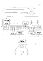
- the production site 10 is provided with a part manufacturing line (pre-process line) 20 for manufacturing parts and a processing line (assembly line) 21 for assembling the manufactured parts.
- the parts manufacturing line 20 is provided with two lines 22 and 23, and the same parts 24 are manufactured from each of the lines 22 and 23.
- a component supply device 31, processing devices 32 and 34, and inspection devices 33 and 35 are provided for the line 30.
- the parts 24 manufactured in the parts manufacturing line 20 are supplied to the line 30 by the parts supply device 31 and processed to be assembled to the substrate of the work 36 by the processing device 32, and processed by the inspection device 33 The examination of Next, the inspected work 36 is processed at a portion unrelated to the part 24 by the processing device 34, and the inspection after the processing is performed by the inspection device 35. Thereafter, processing and inspection are repeated to complete the product.
- the processing devices 32 and 34 are separate from the inspection devices 33 and 35, but may be integrated.
- the inspection devices 33 and 35 provide the data collection device 11 with an inspection file (CSV file) in the CSV format. Further, the inspection devices 33 and 35 provide various information related to the inspection file, such as a file name and a time stamp, from the file system together with the inspection file.
- the provision of the inspection file from the inspection devices 33 and 35 to the data collection device 11 may be performed by wired communication, wireless communication, or a combination of these, or by a recording medium such as a USB (Universal Serial Bus) memory. It may be done.
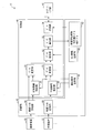
- FIG. 1 shows a schematic configuration of the data acquisition device 11.
- the data collection device 11 is configured to include a control unit 40, a recording unit 41, and a network I / F (interface) unit 42.
- the control unit 40 integrally controls the operations of various components in the data collection device 11, and is configured of, for example, a computer including a CPU (Central Processing Unit) and a memory. And operation control of various composition is performed by making a computer execute a control program. The details of the control unit 40 will be described later.
- a computer including a CPU (Central Processing Unit) and a memory.
- operation control of various composition is performed by making a computer execute a control program. The details of the control unit 40 will be described later.
- the recording unit 41 records information, and is configured of a recording device such as a hard disk or a flash memory. The details of the recording unit 41 will be described later.
- the network I / F unit 42 interfaces the control unit 40 with the communication network 13. Specifically, the network I / F unit 42 connects to the communication network 13 shown in FIG. 2, converts the data from the control unit 40 into a format suitable for the communication network 13 and transmits it to the communication network 13. On the other hand, data from the communication network 13 is converted into a format suitable for processing in the control unit 40 and transmitted to the control unit 40.
- the inspection file recording unit 60 records the inspection file from the inspection devices 33 and 35 for each of the inspection devices 33 and 35. Further, the examination file recording unit 60 records various information related to the examination file, such as a file name and a time stamp, in the directory. As described above, the inspection file is a file in CSV format.
- the extraction condition recording unit 61 records in advance, for each inspection file recording unit 60, extraction conditions for extracting additional information which is information to be added to inspection data of a certain work 36.
- the line information recording unit 62 records, in advance, line information which is information related to a manufacturing line and is information required to rearrange data.
- the examination DB recording unit 63 records the examination DB.
- the inspection DB includes a characteristic value table that stores characteristic values, an NG table that stores NG (No Good) data, and the like. Note that these tables may be separate or identical.
- the additional information extraction unit 50 extracts the additional information to the examination data included in the examination file to be read out from the examination file recording unit 60 based on the extraction condition recorded in the extraction condition recording unit 61.
- the additional information extraction unit 50 transmits the extracted additional information to the data change unit 51.
- the additional information extraction unit 50 first reads out various information related to the inspection file, such as a file name and a time stamp, from the directory of the inspection file recording unit 60. Next, the additional information is extracted based on the extraction condition recorded in the extraction condition recording unit 61 from the read out information. The details of the extraction of the additional information will be described later.
- an argument may be added to the file name, such as “[order number]. Csv [model] [voltage] [channel]”, for example. This argument is also included in the additional information.
- the data change unit 51 changes data included in the examination file read out from the examination file recording unit 60.
- the data changing unit 51 transmits the changed data to the data combining unit 52.
- the data changing unit 51 determines that the inspection data is NG data, and changes the character string to null. In the case of the CSV format, the above character string is changed to a null character string (a character string of length 0). In addition, the data changing unit 51 creates an NG file that includes the NG data that is the character string at the same arrangement position as the inspection data in the inspection file.
- the data changing unit 51 adds additional information related to the inspection file from the additional information extraction unit 50 to the inspection data in the inspection file to obtain characteristic value data. Then, the data changing unit 51 transmits the processed inspection file and the NG file corresponding to the inspection file to the data combining unit 52.
- the data combining unit 52 combines various data received from the plurality of data changing units 51 in units of work 36.
- the data combining unit 52 transmits the combined data to the data writing unit 53.
- the data combining unit 52 rearranges the characteristic value data and the NG data of the work 36 from the data changing unit 51 based on the line information recorded in the line information recording unit 62. Then, the data combining unit 52 transmits the combined characteristic value data and the NG data to the data writing unit 53. The rearrangement of the characteristic value data will be described later.
- the data providing unit 54 reads out and provides various data from the examination DB of the examination DB recording unit 63 in response to an external request. Specifically, when the data providing unit 54 receives a request from the PC 14 via the communication network 13 and the network I / F unit 42, based on the request, the data providing unit 54 receives the request from the inspection DB recorded in the inspection DB recording unit 63. Read out characteristic value data and NG data. Then, the data providing unit 54 provides the read characteristic value data and the NG data to the PC 14 via the network I / F unit 42 and the communication network 13. A specific example of analysis using characteristic value data and NG data will be described later.
- the additional information related to the inspection file is extracted by the additional information extraction unit 50, added to the inspection data in the inspection file by the data changing unit 51, and the characteristics of the inspection DB of the inspection DB recording unit 63. Added to value table. Therefore, not only the inspection data in the inspection file but also the additional information related to the inspection file is added to the characteristic value table, so the data from the inspection devices 33 and 35 is dropped in the characteristic value table. Can be integrated without
- the character changing unit 51 converts the character string to null, and the converted inspection data is processed by the data writing unit 53 for inspection of the inspection DB recording unit 63. It is added to DB's characteristic value table. As a result, since the inspection value or null is included as the inspection data in the characteristic value table and no character string is included, the analysis of the inspection data can be easily performed.
- the character string is associated with the position where the null converted is added to the characteristic value table by the data changing unit 51 and the data writing unit 53, and is added to the NG table of the inspection DB of the inspection DB recording unit 63. Is added. This makes it possible to prevent the loss of information on character strings such as inspection errors and inspection errors. Further, by referring to the character string corresponding to the null, it is possible to determine, for example, what kind of inspection abnormality or inspection error the null is.
- the inspection data for each work 36 acquired from the inspection devices 33 and 35 is arranged in a predetermined order in the data combining unit 52 based on the line information from the line information recording unit 62, and the data writing unit 53 Is added to the above-mentioned characteristic value table. Therefore, since the data included in the characteristic value table are arranged in a predetermined order, data analysis using the characteristic value table can be performed with high accuracy.
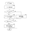
- FIG. 3 shows the flow of processing in the data collection device 11 from the time when the examination file is recorded to the time when the examination DB is updated.
- the additional information extraction unit 50 records additional information on the new examination file in the extraction condition recording unit 61. It extracts based on the extracted extraction conditions (S11).
- the inspection data included in the new inspection file from the inspection file recording unit 60 is a character string (S12)
- the data changing unit 51 changes the character string to null and the inspection data An NG file containing the character string at the same array position is created (S13).
- the data combining unit 52 rearranges the characteristic value data of the work 36 included in the plurality of inspection files based on the line information of the line information recording unit 62 and combines them, while combining the same from the data changing unit 51
- the NG data for each work 36 contained in the NG file is rearranged based on the line information and then combined (S15).
- the data writing unit 53 adds a serial number to each of the combined characteristic value data, and adds the serial number to the characteristic value table in the inspection DB of the inspection DB recording unit 63, and the characteristic value table corresponding to the NG data.
- the serial number given to is added to the NG data and added to the NG table in the inspection DB (S16). Thereafter, the process returns to step S10 to repeat the above operation.
- inspection data is managed in a file format, and inspection files are created for each order (order), for each model of a product in process of manufacture, and for each (direct number).
- additional information on the manufacturing line such as the order name, the model name, and the serial number, is included as part of the file name.
- the data combining unit 52 adds additional information to the inspection data of each work 36 and adds it to the inspection DB.
- the inspection file before interruption of the certain order, the inspection file of the other order, and the inspection file after resumption of the certain order are created. For this reason, since the inspection file before the interruption and after the restart needs to be able to identify that the certain order is divided and executed, the branch name of the order is included in the file name.
- the branch number of the order included in the file name is added to the inspection data of each work 36 as the additional information. This facilitates stratification of inspection data.
- Information included in the file name of the inspection file includes order name (order number), model name, direct (1 job, 2 job, 3 job etc.), operator name, line number of previous process, order branch number, etc. Can be mentioned.
- order name order number
- model name model name
- direct (1 job, 2 job, 3 job etc. direct (1 job, 2 job, 3 job etc.
- operator name line number of previous process
- order branch number etc. Can be mentioned.
- part or all of the above information is combined via a separator. Which information is included in the file name depends on the inspection device. In addition, each information is often expressed by an identifiable number.
- FIG. 4 shows an example of the extraction condition.
- the extraction condition can be described in a structured document such as an Extensible Markup Language (XML) document.
- XML Extensible Markup Language
- the extraction conditions can be set for each of the inspection devices 33 and 35.
- the preceding process line 20 is included in the extraction condition as additional information to be added to the inspection data for the inspection device 33 (inspection device 1), for the inspection device 35 (inspection device 2), The preceding process line 20 is not included in the extraction condition as the additional information.
- the characteristics of the product manufactured in the assembly line 21 may also change depending on the adjustment result by the operator of the assembly line 21. Therefore, the information of the operator can also be the additional information.
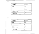
- FIG. 5 shows an example of the file name of the examination file in the form of a list.
- the inspection file shown to (a) of the figure is what the inspection apparatus 33 (inspection machine 1) created, and the inspection file shown to (b) of the figure was created by the inspection apparatus 35 (inspection machine 2) It is a thing. Further, in the illustrated example, file names of a plurality of inspection files are described in the order of creation for each of the inspection devices 33 and 35.
- the order number, model name, direct, operator name, line number of previous process, and branch number of order number , And the separators "_" are arranged in order.
- the line number of the previous process is omitted from the above-mentioned file name relating to the inspection device 1.
- FIG. 6 shows the flow of the additional information extraction process (S11) in the additional information extraction unit 50. As illustrated, first, extraction conditions shown in FIG. 4 are read out from the extraction condition recording unit 61 (S20).
- the file name of the inspection file is divided for each character "_" included in the "separator” tag in the extraction condition.
- the file name “M1121397_A001_2_TANAKA_S1_1.txt” is divided into character strings “M1121397”, “A001", “2”, “TANAKA”, “S1", and "1". Note that the extension (txt) included in the file name is ignored because it is not information on examination data.
- the extracted additional information is associated with the item name based on the extraction condition (S22).
- the divided character string is associated with the item name included in the “item name sequence” tag in the above extraction condition.
- FIG. 7A shows an example of the associated item names and character strings in the form of a table.
- the character string “M1121397” is the order number
- the character string “A001” is the model name
- the character string “2” is immediately
- the character string “TANAKA” is the operator name
- the character string “S1” is The character string "1" is associated with the branch number of the order in the line name of the previous step.
- part or all of the additional information is converted into a code based on the extraction condition (S23).
- the operator name is converted into an ID (identification) code of the operator with reference to the "operator” tag in the extraction condition.
- (B) of FIG. 7 shows an example of the item name and the character string after conversion in the form of a table.
- the operator name "TANAKA” is converted to the ID code "0002".
- the amount of additional information can be suppressed, so the size of the inspection DB can be suppressed, and since the code is easier to process on a computer than a character string, search processing from the inspection DB is performed. Can be done quickly.
- it is desirable to convert other character strings such as the line name, equipment name, and model name of the previous process into the identification code.
- FIG. 8 shows an example of the operator table in the form of a table.
- the examination DB can be searched based on the information on the operator, and the ID code of the search result can be converted to the information on the operator and output. Further, information on the operator may be acquired by referring to an employee DB of a company at which the operator works.
- information including the converted additional information and the item name associated with the additional information is transmitted to the data changing unit 51 (S24). That is, the information shown in (b) of FIG. 7 is transmitted to the data changing unit 51.
- the item name of the additional information can be added to the characteristic value table.
- the user of the PC 14 can easily grasp the added additional information item from the item name.
- the extraction process of the additional information is ended, and the process returns to the original routine.
- the order of data in the inspection DB needs to be matched with the order in which the work 36 is input. This is because if the order of the above data is out of the order of the work 36, accurate analysis can not be performed when performing periodic analysis or comparing the results of individual facilities.
- the equipment for example, inspection apparatus
- the equipment with a slow process may process several workpieces 36 in parallel.
- the order of feeding the work 36 into the line 30 may deviate from the order of inspection of the work 36. Therefore, it is necessary to rearrange the order of the inspection data of the work 36 so as to match the order in which the work 36 is input.
- the processing speed of the processing apparatus is 1 second / 1 and the inspection speed of the inspection apparatus is 3 seconds / 1, 3 units in the inspection process to match the processing time of the processing process and the processing time of the inspection process.
- FIG. 9 shows an example in which three workpieces 36 are inspected in parallel by the inspection device 33.
- the inspection device 33 is provided with inspection units 330 of 1 CH (channel) to 3 CH from the downstream side to the upstream side. Further, in the line 30, an arm 37 and a test stand 38 are further provided.
- the arm 37 mounts the work 36 processed by the processing device 32 on the inspection table 38.
- Three workpieces 36 are mounted on the inspection table 38 by the arm 37.
- the inspection unit 330 of the 1CH, 2CH, and 3CH inspects the work 36 on the right side, the center, and the left side among the three works 36 on the inspection table 38, respectively.
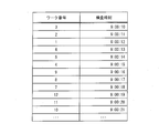
- FIG. 10 respectively show the work numbers and the inspection times inspected by the inspection units 330 of 1CH to 3CH in the inspection apparatus 33 shown in FIG. 9 in the form of a table.
- the time taken for each inspection unit 330 to perform an inspection is 3 ⁇ 1 seconds.
- FIG. 11 shows, in the form of a table, an arrangement of the numbers of the works 36, the examination CH, and the examination time shown in FIGS. 10 (a) to 10 (c).
- (a) of FIG. 11 is arranged in order of examination time. In the case of (a) of the figure, they are not arranged in the order of the numbers of the works 36 (in order of insertion).
- FIG. 12 shows an example in which the inspection device 35 inspects the work 36 after the inspection table 38 is turned back and forth (180 degrees rotation) after the inspection by the inspection device 33.
- FIG. 13 has shown the workpiece
- the time taken for the inspection device 35 to perform the inspection is 1 ⁇ 0.5 seconds.
- they are not arranged in the order of the numbers of the works 36. In this case, rearrangement in consideration of the above inversion is required.
- the line information recording unit 62 records in advance line information necessary to rearrange the inspection data of the work 36, such as the arrangement of each facility on the line 30, the channel contents, etc. ing.
- FIG. 14 shows an example of the line information. As shown, the line information can be described in a structured document such as an XML document.
- FIG. 15 shows the flow of data combining processing in the data combining unit 52.
- line information shown in FIG. 14 is read from the line information recording unit 62 (S40), and it is determined whether a channel tag exists in the read line information (S41).
- the data of the workpiece 36 is arranged in order of examination time (S42).
- the data of the work 36 is arranged based on the content of the channel tag (S43).
- the content of the alignment tag in the channel tag of the inspection device 1 tag is “1CH, 2CH, 3CH”. Therefore, the data of the inspection file of 1 CH ((a) in FIG. 10), the data of the inspection file of 2 CH ((b) of FIG. 10), and the data of the inspection file of 3 CH ((c) in FIG. 10) are selected in order By arranging them and repeating this, it is possible to arrange the data in the order of workpiece input ((b) in FIG. 11).
- the arranged data is rearranged based on the inversion tag (S45). Thereafter, the data combining process is finished, and the original routine is returned to.
- the number of works in the reverse tag of the inspection device 2 tag is three. Therefore, the data of the inspection file of the inspection machine 2 (FIG. 13) can be arranged in the data of the work input order by reversing (reversed) the order of the data of the three works and repeating this.
- FIG. 16 shows an example of the contents of the examination file created by the examination device 35 shown in FIG. 12 and acquired by the data collection device 11 in the form of a table
- FIG. 16 and FIG. 17 An example of the contents of the characteristic value table and the NG table recorded in the recording unit 63 is shown in a table format.
- the items in each column are, in order from the left, a work number (work ID), an inspection order, measurement items 1 to 6, an inspection result, a measurement time, and a channel number.
- the characteristic value table is for storing characteristic values. As shown in (a) of FIG. 17, all data stored in the characteristic value table is numerical data. Therefore, by using the characteristic value table recorded in the inspection DB recording unit 63, data analysis can be performed by the PC 14. For example, the data of the above-mentioned characteristic value table is read every hour, and the transition of the characteristic value is examined by calculating the average value and the dispersion value for each channel, or the record including null is counted to calculate the yield. By doing this, the status of the inspection machine can be checked.
- the types of numerical values (integers, natural numbers, single precision, double precision, etc.) of each item in the specific value table are the same as the types of numerical values of corresponding items in the examination file shown in FIG.
- the NG table character strings of inspection error and inspection abnormality are stored.
- the data stored in the NG table is numerical data only for the work ID, and the others are character string data.
- the character string when the inspection file includes a character string such as an inspection error or an inspection abnormality, the character string is converted to null and stored in the characteristic value table.
- a character string such as an inspection error or an inspection abnormality
- the character string is converted to null and stored in the characteristic value table.
- the characteristic value table shown in (a) of FIG. 17 the character string is converted to null.
- the PC 14 can analyze an inspection error, an inspection abnormality, and the like.
- an inspection error can be totaled by counting the character string which shows the inspection error in a predetermined period using the said NG table.
- By displaying the tabulation results in a table and a graph it is possible to confirm the tendency of inspection errors (increase, decrease, etc.), and to confirm the condition of equipment.
- the NG table is created, the tallying and the confirmation become possible.
- the additional information such as the order information is stored in the characteristic value table, and therefore, it is possible to count in the additional information unit.
- the recording unit 41 further includes an allowable range recording unit for storing the allowable range (upper limit and lower limit) of the inspection data
- the data changing unit 51 further includes the inspection data in the inspection file from the inspection file recording unit 60 described above. If out of the allowable range, a string indicating abnormality may be added to the NG file. In this case, the character string indicating the abnormality is added to the NG table in association with the position where the inspection data is added to the characteristic value table. Therefore, by referring to the NG table, it is possible to analyze an inspection error and an inspection abnormality. In addition, since inspection data is added to the above-mentioned characteristic value table even if it is out of the allowable range, loss of information can be prevented.
- Some inspection devices 33 and 35 do not create data when there is no work (hereinafter, this case is referred to as “the case without work”). In this case, the periodicity of the characteristic value data collected in the characteristic value table is shifted, which makes it difficult to execute data analysis.
- FIG. 18 shows, in the form of a table, an arrangement of workpiece numbers, inspection channels, and inspection times when no workpiece occurs.
- the data is not output from the information defined by the ⁇ Inspector 1> ⁇ No Work> tag. Therefore, a place where data of 1CH to 3CH are not prepared at the same time is a place where no work occurs.
- the inspection unit 330 of 3CH inspects the work 3 at the start of the inspection, but no work exists in the inspection unit 330 of 1CH ⁇ 2CH. For this reason, as shown in FIG. 18, data of 3 CH exists at the inspection time “9:00:00” which is the start time of the inspection, but data of 1 CH ⁇ 2 CH does not exist. Also in this case, data indicating no work may be inserted as data of 1CH ⁇ 2CH at the inspection time “9:00:00”.
- the inspection unit 330 of 3CH inspects the workpiece 6, and the inspection unit 330 of 2CH inspects the workpiece 2, but no workpiece exists in the inspection unit 330 of 1CH. For this reason, as shown in FIG. 18, at the inspection time “9:00:03” which is the next inspection time, data of 2CH ⁇ 3CH is present, but data of 1CH is not present. Also in this case, data indicating no work may be inserted as data of 1 CH at the inspection time “9:00:03”.
- FIG. 19 shows, in the form of a table, an arrangement of workpiece numbers to be inspected by the inspection device 2 and inspection times.
- (A) of the figure is actual data. If three pieces of this data are rearranged, it becomes the work insertion order as shown in FIG. Next, the inspection times are changed three by three so that the order of the inspection times is the order in which the work is input. As a result, as shown in (c) of the figure, it becomes data in which the measurement times are arranged in the order in which the work is input.
- any one of the three workpieces placed on the inspection table 38 is inspected by the inspection unit 330 of 3CH, and another one is inspected by the inspection unit 330 of 2CH. And the remaining one is inspected by the inspection unit 330 of 1 CH, and the inspection by the inspection machine 1 is completed.
- the data combining unit 52 After arranging the inspection data for each work 36 in a predetermined order, the data combining unit 52 also arranges the measurement times in the characteristic value table in order by rearranging the measurement times for each work 36 in the early order. This makes it easy to execute data analysis based on the measurement time.
- the characteristic value table shown in (a) of FIG. 17 is recorded in the inspection DB recording unit 63.
- data are arranged in the order in which the work is input, nulls are stored in places where measured data are abnormal values, and measurement times are arranged in the order in which the work is input.
- the data of the workpiece number 23 is data without a workpiece, and nulls are stored in items other than the workpiece number, the measurement time, and the channel number.
- collection of inspection data from the inspection devices 33 and 35 is described, but collection of measurement data from the measurement device, collection of setting data from the processing devices 32 and 34, etc.
- the present invention can be applied to the collection of data from various facilities provided.
- each block of the data collection device 11, in particular, the control unit 40 may be configured by hardware logic, or may be realized by software using a CPU as follows.
- the data collection device 11 is a CPU (central processing unit) that executes instructions of a control program that realizes each function, a ROM (read only memory) that stores the program, and a RAM (random access memory) that expands the program.
- a storage device such as a memory for storing the program and various data.
- the object of the present invention is a recording medium in which a program code (an executable program, an intermediate code program, a source program) of a control program of the data collecting apparatus 11 which is software that realizes the functions described above is readable by computer. This can also be achieved by supplying the data collection device 11 and the computer (or CPU or MPU) reading out and executing the program code recorded in the recording medium.
- Examples of the recording medium include tape systems such as magnetic tapes and cassette tapes, magnetic disks such as floppy (registered trademark) disks / hard disks, and disks including optical disks such as CD-ROM / MO / MD / DVD / CD-R.
- a system a card system such as an IC card (including a memory card) / optical card, or a semiconductor memory system such as a mask ROM / EPROM / EEPROM / flash ROM can be used.
- the data collection device 11 may be configured to be connectable to a communication network, and the program code may be supplied via the communication network.
- the communication network is not particularly limited.
- the Internet intranet, extranet, LAN, ISDN, VAN, CATV communication network, virtual private network, telephone network, mobile communication network, satellite communication A network etc. are available.
- the transmission medium constituting the communication network is not particularly limited.
- IEEE1394, USB power line carrier, cable TV line, telephone line, wired line such as ADSL line, infrared ray such as IrDA or remote control, Bluetooth ( It is also possible to use a radio such as a registered trademark), an 802.11 radio, an HDR, a mobile telephone network, a satellite link, and a terrestrial digital network.
- the present invention can also be realized in the form of a computer data signal embedded in a carrier wave, in which the program code is embodied by electronic transmission.
- the data collection device is a data collection device that collects data from each facility of a manufacturing line and adds the collected data to a database, and the above-mentioned problem is solved.
- examples of values that can be processed as a numeric string and that can be distinguished from measured values include null, 0, a negative value, and the like.
- a control method of a data collection device is a control method of a data collection device which collects data from each facility of a manufacturing line and adds the collected data to a database.
- the acquisition step of acquiring measurement data from the equipment and when the measurement data acquired in the acquisition step includes a character string the character string can be processed as a numerical string, And converting the measurement data into a value distinguishable from the value and adding the measurement data to the database.
- the measurement data when the measurement data includes a character string, the measurement data is added to the database after converting the character string to null.
- the measurement data or null is included as the measurement data in the database and no character string is included, the analysis of the measurement data can be easily performed.
- the adding unit further adds the character string to the character string table in association with the position where the converted value is added to the database.
- the string is added to the string table in association with the position at which the converted null is added to the database.
- the string is added to the string table in association with the position at which the converted null is added to the database.
- it is possible to prevent loss of information on character strings such as measurement errors and measurement errors.
- the character string corresponding to the null it is possible to determine, for example, what kind of measurement abnormality or measurement error the null is.
- the data collection apparatus further includes a tolerance range recording unit for recording the tolerance range of the measurement data, and the additional means further includes measurement data acquired by the acquisition unit from the tolerance range recording unit.
- the character string indicating abnormality may be added to the character string table in association with the position where the measurement data is added to the database. In this case, it is possible to analyze measurement errors and measurement abnormalities by referring to the character string table.
- measurement data is added to the above-mentioned database even if it is out of the allowable range, it is possible to prevent loss of information.
- a data collection device is a data collection device which collects data from each facility of a manufacturing line and adds the collected data to a database, and the above facility and the facility for solving the above-mentioned problems.
- a line information recording unit that stores line information including a correspondence with the rule of the order of the workpieces to be processed, an acquisition unit that acquires data for each workpiece in the facility, It is characterized by comprising: arranging means for arranging data of each work acquired by the acquisition means in a predetermined order; and addition means for adding data of each work arranged by the arranging means to the database.
- a control method of a data collection device is a control method of a data collection device which collects data from each facility of a manufacturing line and adds the collected data to a database.
- the line information including the correspondence between the acquisition step of acquiring data for each work in the equipment, the equipment, and the order rule of the work processed by the equipment is read from the recording unit, and the read line information is read.
- predetermined order there may be mentioned an order of insertion of work onto the manufacturing line, a predetermined time order, a predetermined lot order, a predetermined model order, and the like. Further, as an example of the above-mentioned order rule, there are a plurality of channels, measurement errors, inversions and the number thereof, measurement time, and the like.
- the data for each work acquired from the equipment is arranged in a predetermined order based on the line information from the line information recording unit, and is added to the database. Therefore, since the data included in the database are arranged in a predetermined order, data analysis using the database can be performed with high accuracy.
- the data for each work includes the measurement time of the data
- the line information includes measurement of the equipment and a period required for the equipment to measure.
- the arrangement means further includes a correspondence relationship with the period, and the arrangement means measures the measurement period corresponding to the equipment, with the difference in measurement time in the data of the adjacent works based on the line information from the line information recording unit. If larger, it is preferable to insert data indicating that there is no target work between the data of the works, and then to arrange the data for each work in a predetermined order.
- the data without a workpiece preferably includes workpiece identification information for identifying a workpiece, and one of the measurement times in the data of the adjacent workpieces or the time between the measurement times is included as the measurement time. Is preferred. In addition, the other values in the data without work may be null.
- the data for each work includes the measurement time of the data, and the arrangement means arranges the data for each work in a predetermined order, and then the work for each work is performed.
- the measurement times may be changed to be arranged in a predetermined order.
- the measurement times are also arranged in order, which facilitates the execution of data analysis based on the measurement times.
- prescribed order regarding the said measurement time the injection
- a data collection device is a data collection device that collects data from each facility of a manufacturing line and adds the collected data to a database, and a file including the data described above to solve the above problems.
- An acquisition unit for acquiring a file name from the facility, an extraction unit for extracting additional information on the data from the file name acquired by the acquisition unit, and a file for which the acquisition unit acquires the additional information extracted by the extraction unit And adding means for adding to the database in addition to the above data.
- a control method of a data collection device is a control method of a data collection device which collects data from each facility of a manufacturing line and adds the collected data to a database.
- the file and the file name are acquired from the facility, and the additional information on the data in the file is extracted from the acquired file name. Then, the extracted additional information is added to the data in the file and added to the database. Therefore, not only the data in the file but also the additional information contained in the file name is added to the database, so that data from the facility can be integrated into the database without missing the additional information.
- the file name includes a combination of a plurality of the additional information via a separator
- the extraction condition recording unit records the extraction condition for extracting the additional information.
- the extraction condition further includes the information of the separator, the order of the additional information, and the correspondence relationship of the item names, and the extraction unit is based on the extraction condition from the extraction condition recording unit.
- extracting the additional information from the file name and associating the extracted additional information with the item name, and the adding unit further adds an item name associated with the additional information to the database. Is preferred. In this case, the user of the database can easily grasp the added additional information item from the item name.
- the control program can cause the computer to execute each step in the data collection apparatus. Furthermore, by storing the control program in a computer readable recording medium, the control program can be executed on any computer.
- the data collection apparatus can integrate data from each facility of a manufacturing line without loss of information or in an orderly manner. Therefore, not only inspection data from the inspection apparatus but also any measuring apparatus, processing apparatus, etc. It can be applied to data collection from data facilities and data analysis.
Landscapes
- Engineering & Computer Science (AREA)
- General Engineering & Computer Science (AREA)
- Manufacturing & Machinery (AREA)
- Quality & Reliability (AREA)
- Physics & Mathematics (AREA)
- General Physics & Mathematics (AREA)
- Automation & Control Theory (AREA)
- General Factory Administration (AREA)
- Management, Administration, Business Operations System, And Electronic Commerce (AREA)
- Debugging And Monitoring (AREA)
- Testing And Monitoring For Control Systems (AREA)
- Information Retrieval, Db Structures And Fs Structures Therefor (AREA)
Abstract
Description
SQL(Structured Query Language)を利用することにより、上記DBからのデータの検索、ソート、カウントなどを容易に実行することができる。
日付ごと、オーダごとなどに分割されたファイルを上記DBに追加することで、複数のファイルにおけるデータを一連のデータとして利用することができる。これにより、日付、オーダなどを跨いだ長期間のデータについて、監視、同一機種ごとの集計などが可能となる。
複数の製造ラインからのデータをDB化することで、該データの監視および解析を同一のDBにアクセスすることで可能になる。また、データのバックアップ等を一括で実行できるため管理が容易になる。
上記DBを管理するDBMS(Database Management System)を有するサーバに通信ネットワークを介して接続されたPC(Personal Computer)から、ODBC(Open Database Connectivity)を介して上記DBMSにアクセスすることにより、遠隔でのデータ監視や解析が可能になる。
10 生産現場
11 データ収集装置
13 通信ネットワーク
14 PC
20 前工程ライン・部品製造ライン
21 加工ライン・組立ライン
22・23 ライン
24 部品
30 ライン
31 部品供給装置
32・34 加工装置
33・35 検査装置
36 ワーク
37 アーム
38 検査台
40 制御部
41 記録部
42 ネットワークI/F部
50 付加情報抽出部(抽出手段)
51 データ変更部(追加手段)
52 データ結合部(追加手段、配列手段)
53 データ書込部(追加手段)
54 データ提供部
60 検査ファイル記録部(取得手段)
61 抽出条件記録部
62 ライン情報記録部
63 検査DB記録部
330 検査部
Claims (14)
- 製造ラインの各設備からのデータを収集し、収集したデータをデータベースに追加するデータ収集装置であって、
上記設備から計測データを取得する取得手段と、
上記取得手段が取得した計測データに文字列が含まれている場合、該文字列を、数値列として処理できる値であって、計測値と区別できる値に変換して上記計測データを上記データベースに追加する追加手段とを備えることを特徴とするデータ収集装置。 - 上記追加手段は、さらに、変換された値が上記データベースに追加された位置に対応付けて、上記文字列を文字列テーブルに追加することを特徴とする請求項1に記載のデータ収集装置。
- 上記計測データの許容範囲を記録する許容範囲記録部をさらに備えており、
上記追加手段は、さらに、上記取得手段が取得した計測データが上記許容範囲記録部からの許容範囲に含まれていない場合、上記計測データが上記データベースに追加された位置に対応付けて、異常を示す文字列を文字列テーブルに追加することを特徴とする請求項1または2に記載のデータ収集装置。 - 製造ラインの各設備からのデータを収集し、収集したデータをデータベースに追加するデータ収集装置であって、
上記設備と、該設備が処理するワークの順序の規則との対応関係を含むライン情報を記憶するライン情報記録部と、
上記設備におけるワークごとのデータを取得する取得手段と、
上記ライン情報記録部からのライン情報に基づいて、上記取得手段が取得したワークごとのデータを所定の順序に配列する配列手段と、
該配列手段が配列したワークごとのデータを上記データベースに追加する追加手段とを備えることを特徴とするデータ収集装置。 - 上記ワークごとのデータには、該データの計測時刻を含んでおり、
上記ライン情報には、上記設備と、該設備が計測に必要な期間である計測期間との対応関係をさらに含んでおり、
上記配列手段は、上記ライン情報記録部からのライン情報に基づいて、隣り合う上記ワークどうしのデータにおける計測時刻の差が、上記設備に対応する計測期間よりも大きい場合、上記ワークどうしのデータの間に、対象となるワークが存在しなかったことを示すデータを挿入してから、上記ワークごとのデータを所定の順序に配列することを特徴とする請求項4に記載のデータ収集装置。 - 上記ワークごとのデータには、該データの計測時刻を含んでおり、
上記配列手段は、上記ワークごとのデータを所定の順序に配列した後、上記ワークごとの計測時刻を、所定の順序に並ぶように変更することを特徴とする請求項4に記載のデータ収集装置。 - 製造ラインの各設備からのデータを収集し、収集したデータをデータベースに追加するデータ収集装置であって、
上記データを含むファイルおよびファイル名を上記設備から取得する取得手段と、
該取得手段が取得したファイル名から上記データに関する付加情報を抽出する抽出手段と、
該抽出手段が抽出した付加情報を、上記取得手段が取得したファイル内の上記データに追加して、上記データベースに追加する追加手段とを備えることを特徴とするデータ収集装置。 - 上記ファイル名は、複数の上記付加情報がセパレータを介して結合したものを含んでおり、
上記付加情報を抽出するための抽出条件を記録する抽出条件記録部をさらに備えており、
該抽出条件は、上記セパレータの情報と、上記付加情報の順序および項目名の対応関係とを含んでおり、
該抽出手段は、上記抽出条件記録部からの抽出条件に基づいて、上記ファイル名から上記付加情報を抽出し、抽出された付加情報に上記項目名を対応付けており、
上記追加手段は、さらに、上記付加情報に対応付けられた項目名を上記データベースに追加することを特徴とする請求項7に記載のデータ収集装置。 - 製造ラインの各設備からのデータを収集し、収集したデータをデータベースに追加するデータ収集装置の制御方法であって、
上記設備から計測データを取得する取得ステップと、
上記取得ステップにて取得された計測データに文字列が含まれている場合、該文字列を、数値列として処理できる値であって、計測値と区別できる値に変換して上記計測データを上記データベースに追加する追加ステップとを含むことを特徴とするデータ収集装置の制御方法。 - 製造ラインの各設備からのデータを収集し、収集したデータをデータベースに追加するデータ収集装置の制御方法であって、
上記設備におけるワークごとのデータを取得する取得ステップと、
上記設備と、該設備が処理するワークの順序の規則との対応関係を含むライン情報を記録部から読み出し、読み出したライン情報に基づいて、上記取得ステップにて取得されたワークごとのデータを所定の順序に配列する配列ステップと、
該配列ステップにて配列されたワークごとのデータを上記データベースに追加する追加ステップとを含むことを特徴とするデータ収集装置の制御方法。 - 製造ラインの各設備からのデータを収集し、収集したデータをデータベースに追加するデータ収集装置の制御方法であって、
上記データを含むファイルおよびファイル名を上記設備から取得する取得ステップと、
該取得ステップにて取得されたファイル名から上記データに関する付加情報を抽出する抽出ステップと、
該抽出ステップにて抽出された付加情報を、上記取得ステップにて取得されたファイル内の上記データに追加して、上記データベースに追加する追加ステップとを含むことを特徴とするデータ収集装置の制御方法。 - 製造ラインの各設備からのデータを収集し、収集したデータをデータベースに追加するデータ収集装置を動作させるための制御プログラムにおいて、
上記設備から計測データを取得する取得ステップと、
上記取得ステップにて取得された計測データに文字列が含まれている場合、該文字列を、数値列として処理できる値であって、計測値と区別できる値に変換して上記計測データを上記データベースに追加する追加ステップとをコンピュータに実行させるための制御プログラム。 - 製造ラインの各設備からのデータを収集し、収集したデータをデータベースに追加するデータ収集装置を動作させるための制御プログラムにおいて、
上記設備におけるワークごとのデータを取得する取得ステップと、
上記設備と、該設備が処理するワークの順序の規則との対応関係を含むライン情報を記録部から読み出し、読み出したライン情報に基づいて、上記取得ステップにて取得されたワークごとのデータを所定の順序に配列する配列ステップと、
該配列ステップにて配列されたワークごとのデータを上記データベースに追加する追加ステップとをコンピュータに実行させるための制御プログラム。 - 製造ラインの各設備からのデータを収集し、収集したデータをデータベースに追加するデータ収集装置を動作させるための制御プログラムにおいて、
上記データを含むファイルおよびファイル名を上記設備から取得する取得ステップと、
該取得ステップにて取得されたファイル名から上記データに関する付加情報を抽出する抽出ステップと、
該抽出ステップにて抽出された付加情報を、上記取得ステップにて取得されたファイル内の上記データに追加して、上記データベースに追加する追加ステップとをコンピュータに実行させるための制御プログラム。
Priority Applications (1)
| Application Number | Priority Date | Filing Date | Title |
|---|---|---|---|
| CN201180065611.9A CN103314335B (zh) | 2011-01-31 | 2011-03-18 | 数据收集装置、以及该数据收集装置的控制方法和控制程序 |
Applications Claiming Priority (2)
| Application Number | Priority Date | Filing Date | Title |
|---|---|---|---|
| JP2011-018024 | 2011-01-31 | ||
| JP2011018024A JP5327239B2 (ja) | 2011-01-31 | 2011-01-31 | データ収集装置、並びに、該データ収集装置の制御方法および制御プログラム |
Publications (1)
| Publication Number | Publication Date |
|---|---|
| WO2012105063A1 true WO2012105063A1 (ja) | 2012-08-09 |
Family
ID=46602302
Family Applications (1)
| Application Number | Title | Priority Date | Filing Date |
|---|---|---|---|
| PCT/JP2011/056579 Ceased WO2012105063A1 (ja) | 2011-01-31 | 2011-03-18 | データ収集装置、並びに、該データ収集装置の制御方法および制御プログラム |
Country Status (4)
| Country | Link |
|---|---|
| JP (1) | JP5327239B2 (ja) |
| CN (3) | CN103314335B (ja) |
| MY (3) | MY171680A (ja) |
| WO (1) | WO2012105063A1 (ja) |
Families Citing this family (10)
| Publication number | Priority date | Publication date | Assignee | Title |
|---|---|---|---|---|
| JP6270395B2 (ja) * | 2013-09-26 | 2018-01-31 | 株式会社日立国際電気 | 基板処理装置及び半導体装置の製造方法並びにプログラム |
| CN106663048B (zh) * | 2014-06-12 | 2018-06-22 | 三菱电机株式会社 | 日志记录系统、日志记录装置、数据日志记录方法 |
| JP6399586B2 (ja) * | 2014-10-03 | 2018-10-03 | エヌ・ティ・ティ・インフラネット株式会社 | 点検データ管理装置及び点検データ管理方法 |
| JP6407946B2 (ja) * | 2016-12-12 | 2018-10-17 | ファナック株式会社 | 機器情報及び位置情報の管理装置及び管理システム |
| JP7134453B2 (ja) * | 2017-09-05 | 2022-09-12 | 株式会社Kmc | 生産監視システム及び生産監視方法 |
| CN107765885B (zh) * | 2017-09-13 | 2021-10-19 | 浙江电力建设监理有限公司 | 用于智能监控管理的输入验证方法及系统 |
| KR102009253B1 (ko) * | 2018-02-14 | 2019-08-09 | 호전실업 주식회사 | 다품종 소량 의복 생산을 위한 모듈화 의류 제조 방법 및 모듈화 의류 제조 시스템 |
| CN110609820A (zh) * | 2018-05-28 | 2019-12-24 | 吴俊逸 | 基于文字挖掘的建模系统以及使用其的建模方法 |
| JP7352494B2 (ja) * | 2020-03-05 | 2023-09-28 | 堺ディスプレイプロダクト株式会社 | 生産情報管理システム |
| WO2025234232A1 (ja) * | 2024-05-08 | 2025-11-13 | パナソニックIpマネジメント株式会社 | 情報処理装置、情報処理方法およびプログラム |
Citations (4)
| Publication number | Priority date | Publication date | Assignee | Title |
|---|---|---|---|---|
| JPH09289396A (ja) * | 1996-04-24 | 1997-11-04 | Matsushita Electric Ind Co Ltd | 設備のメンテナンス方法 |
| JP2004029971A (ja) * | 2002-06-21 | 2004-01-29 | Fujitsu Ltd | データ解析方法 |
| JP2009116395A (ja) * | 2007-11-01 | 2009-05-28 | Mitsubishi Electric Corp | データ形式変換装置及びデータ形式変換プログラム及びデータ形式変換方法 |
| JP2010033391A (ja) * | 2008-07-30 | 2010-02-12 | Fujifilm Corp | 生産システム及びその処理方法 |
Family Cites Families (7)
| Publication number | Priority date | Publication date | Assignee | Title |
|---|---|---|---|---|
| US7953842B2 (en) * | 2003-02-19 | 2011-05-31 | Fisher-Rosemount Systems, Inc. | Open network-based data acquisition, aggregation and optimization for use with process control systems |
| US7647301B2 (en) * | 2003-08-08 | 2010-01-12 | Open-Circuit, Ltd. | Information provision apparatus, format separation apparatus, information provision method and program |
| JP3705296B1 (ja) * | 2004-04-30 | 2005-10-12 | オムロン株式会社 | 品質制御装置およびその制御方法、品質制御プログラム、並びに該プログラムを記録した記録媒体 |
| JP2005316826A (ja) * | 2004-04-30 | 2005-11-10 | Fujitsu Ltd | トレーサビリティ管理データ作成方法、トレーサビリティ管理データ作成装置、およびトレーサビリティ管理データ作成プログラム |
| JP4321443B2 (ja) * | 2004-11-16 | 2009-08-26 | オムロン株式会社 | 特定装置、加工処理システム、特定装置の制御方法、特定装置の制御プログラム、特定装置の制御プログラムを記録した記録媒体 |
| JP4337841B2 (ja) * | 2006-06-07 | 2009-09-30 | オムロン株式会社 | データ表示装置およびその制御方法、データ表示装置制御プログラム、ならびに該プログラムを記録した記録媒体 |
| CN101609331B (zh) * | 2009-07-30 | 2011-03-23 | 西安科技大学 | 一种适用于工业过程控制中的数据存储和读取方法 |
-
2011
- 2011-01-31 JP JP2011018024A patent/JP5327239B2/ja active Active
- 2011-03-18 MY MYPI2013002584A patent/MY171680A/en unknown
- 2011-03-18 CN CN201180065611.9A patent/CN103314335B/zh active Active
- 2011-03-18 MY MYPI2018001225A patent/MY193471A/en unknown
- 2011-03-18 WO PCT/JP2011/056579 patent/WO2012105063A1/ja not_active Ceased
- 2011-03-18 CN CN201510185123.1A patent/CN104914820B/zh active Active
- 2011-03-18 CN CN201510184564.XA patent/CN104914818B/zh active Active
- 2011-03-18 MY MYPI2018001226A patent/MY189890A/en unknown
Patent Citations (4)
| Publication number | Priority date | Publication date | Assignee | Title |
|---|---|---|---|---|
| JPH09289396A (ja) * | 1996-04-24 | 1997-11-04 | Matsushita Electric Ind Co Ltd | 設備のメンテナンス方法 |
| JP2004029971A (ja) * | 2002-06-21 | 2004-01-29 | Fujitsu Ltd | データ解析方法 |
| JP2009116395A (ja) * | 2007-11-01 | 2009-05-28 | Mitsubishi Electric Corp | データ形式変換装置及びデータ形式変換プログラム及びデータ形式変換方法 |
| JP2010033391A (ja) * | 2008-07-30 | 2010-02-12 | Fujifilm Corp | 生産システム及びその処理方法 |
Also Published As
| Publication number | Publication date |
|---|---|
| MY193471A (en) | 2022-10-14 |
| JP2012159942A (ja) | 2012-08-23 |
| MY189890A (en) | 2022-03-17 |
| CN104914820B (zh) | 2017-11-10 |
| JP5327239B2 (ja) | 2013-10-30 |
| CN104914818A (zh) | 2015-09-16 |
| CN104914818B (zh) | 2017-08-29 |
| CN104914820A (zh) | 2015-09-16 |
| CN103314335B (zh) | 2016-04-27 |
| CN103314335A (zh) | 2013-09-18 |
| MY171680A (en) | 2019-10-23 |
Similar Documents
| Publication | Publication Date | Title |
|---|---|---|
| JP5327239B2 (ja) | データ収集装置、並びに、該データ収集装置の制御方法および制御プログラム | |
| US12461513B2 (en) | Visualization system | |
| CN113255307A (zh) | 一种电力系统智能报表方法及系统 | |
| CN115097376B (zh) | 计量设备的校验数据的处理方法、装置和计算机设备 | |
| JP5516797B2 (ja) | データ収集装置、並びに、該データ収集装置の制御方法および制御プログラム | |
| JP5672336B2 (ja) | データ収集装置、並びに、該データ収集装置の制御方法および制御プログラム | |
| US7054699B2 (en) | Process management system and production management system | |
| JP5663860B2 (ja) | 製造履歴情報管理装置および方法 | |
| CN120909904A (zh) | 基于多维度的软件开发评估方法及装置、电子设备 | |
| CN114662910A (zh) | 一种cnc设备实时监控无感报工系统及方法 | |
| CN112488482B (zh) | 基于指标体系的自动化作业方法及系统 | |
| Long | A quality assurance protocol for radiocarbon dating laboratories | |
| US11256708B2 (en) | Method of creating process protocols | |
| CN121073274B (zh) | 一种烟草对标体系智能预警辅助决策方法及其系统 | |
| JP2004206454A (ja) | 品質問題の統計的解決作業管理システムとそれを用いた作業管理方法 | |
| Syaputra | Design and Development of a Web-Based Calibration Management Application to Improve Calibration Data Recording and Scheduling | |
| CN121328522A (zh) | 一种卫星批产产线的生产bom文件解析方法 | |
| CN119805022A (zh) | 一种用于声表面波滤波器的全自动智能测试方法 | |
| CN118195404A (zh) | 自动化履约管理方法、装置、计算机设备及存储介质 | |
| Srinivasan | Application of information technology and statistical process control in pharmaceutical quality assurance & compliance | |
| CN117371721A (zh) | 特殊过程确认管理方法及系统 | |
| CN120492249A (zh) | 测试订单的管理方法、装置、电子设备及存储介质 | |
| CN120448389A (zh) | 一种工程造价数据存储处理方法及装置 | |
| CN116933761A (zh) | 一种料号数据自动对比方法、系统、存储介质及电子设备 | |
| CN120406295A (zh) | 一种数控机床数字主线系统 |
Legal Events
| Date | Code | Title | Description |
|---|---|---|---|
| WWE | Wipo information: entry into national phase |
Ref document number: 201180065611.9 Country of ref document: CN |
|
| 121 | Ep: the epo has been informed by wipo that ep was designated in this application |
Ref document number: 11857737 Country of ref document: EP Kind code of ref document: A1 |
|
| NENP | Non-entry into the national phase |
Ref country code: DE |
|
| WWE | Wipo information: entry into national phase |
Ref document number: 1301004219 Country of ref document: TH |
|
| 122 | Ep: pct application non-entry in european phase |
Ref document number: 11857737 Country of ref document: EP Kind code of ref document: A1 |