WO2012104960A1 - ハイブリッド車両の駆動制御装置 - Google Patents
ハイブリッド車両の駆動制御装置 Download PDFInfo
- Publication number
- WO2012104960A1 WO2012104960A1 PCT/JP2011/051908 JP2011051908W WO2012104960A1 WO 2012104960 A1 WO2012104960 A1 WO 2012104960A1 JP 2011051908 W JP2011051908 W JP 2011051908W WO 2012104960 A1 WO2012104960 A1 WO 2012104960A1
- Authority
- WO
- WIPO (PCT)
- Prior art keywords
- torque
- target
- motor generator
- motor
- engine
- Prior art date
- Legal status (The legal status is an assumption and is not a legal conclusion. Google has not performed a legal analysis and makes no representation as to the accuracy of the status listed.)
- Ceased
Links
Images




Classifications
-
- B—PERFORMING OPERATIONS; TRANSPORTING
- B60—VEHICLES IN GENERAL
- B60W—CONJOINT CONTROL OF VEHICLE SUB-UNITS OF DIFFERENT TYPE OR DIFFERENT FUNCTION; CONTROL SYSTEMS SPECIALLY ADAPTED FOR HYBRID VEHICLES; ROAD VEHICLE DRIVE CONTROL SYSTEMS FOR PURPOSES NOT RELATED TO THE CONTROL OF A PARTICULAR SUB-UNIT
- B60W20/00—Control systems specially adapted for hybrid vehicles
- B60W20/10—Controlling the power contribution of each of the prime movers to meet required power demand
- B60W20/11—Controlling the power contribution of each of the prime movers to meet required power demand using model predictive control [MPC] strategies, i.e. control methods based on models predicting performance
-
- B—PERFORMING OPERATIONS; TRANSPORTING
- B60—VEHICLES IN GENERAL
- B60K—ARRANGEMENT OR MOUNTING OF PROPULSION UNITS OR OF TRANSMISSIONS IN VEHICLES; ARRANGEMENT OR MOUNTING OF PLURAL DIVERSE PRIME-MOVERS IN VEHICLES; AUXILIARY DRIVES FOR VEHICLES; INSTRUMENTATION OR DASHBOARDS FOR VEHICLES; ARRANGEMENTS IN CONNECTION WITH COOLING, AIR INTAKE, GAS EXHAUST OR FUEL SUPPLY OF PROPULSION UNITS IN VEHICLES
- B60K6/00—Arrangement or mounting of plural diverse prime-movers for mutual or common propulsion, e.g. hybrid propulsion systems comprising electric motors and internal combustion engines
- B60K6/20—Arrangement or mounting of plural diverse prime-movers for mutual or common propulsion, e.g. hybrid propulsion systems comprising electric motors and internal combustion engines the prime-movers consisting of electric motors and internal combustion engines, e.g. HEVs
- B60K6/42—Arrangement or mounting of plural diverse prime-movers for mutual or common propulsion, e.g. hybrid propulsion systems comprising electric motors and internal combustion engines the prime-movers consisting of electric motors and internal combustion engines, e.g. HEVs characterised by the architecture of the hybrid electric vehicle
- B60K6/44—Series-parallel type
- B60K6/445—Differential gearing distribution type
-
- B—PERFORMING OPERATIONS; TRANSPORTING
- B60—VEHICLES IN GENERAL
- B60K—ARRANGEMENT OR MOUNTING OF PROPULSION UNITS OR OF TRANSMISSIONS IN VEHICLES; ARRANGEMENT OR MOUNTING OF PLURAL DIVERSE PRIME-MOVERS IN VEHICLES; AUXILIARY DRIVES FOR VEHICLES; INSTRUMENTATION OR DASHBOARDS FOR VEHICLES; ARRANGEMENTS IN CONNECTION WITH COOLING, AIR INTAKE, GAS EXHAUST OR FUEL SUPPLY OF PROPULSION UNITS IN VEHICLES
- B60K6/00—Arrangement or mounting of plural diverse prime-movers for mutual or common propulsion, e.g. hybrid propulsion systems comprising electric motors and internal combustion engines
- B60K6/20—Arrangement or mounting of plural diverse prime-movers for mutual or common propulsion, e.g. hybrid propulsion systems comprising electric motors and internal combustion engines the prime-movers consisting of electric motors and internal combustion engines, e.g. HEVs
- B60K6/22—Arrangement or mounting of plural diverse prime-movers for mutual or common propulsion, e.g. hybrid propulsion systems comprising electric motors and internal combustion engines the prime-movers consisting of electric motors and internal combustion engines, e.g. HEVs characterised by apparatus, components or means specially adapted for HEVs
- B60K6/36—Arrangement or mounting of plural diverse prime-movers for mutual or common propulsion, e.g. hybrid propulsion systems comprising electric motors and internal combustion engines the prime-movers consisting of electric motors and internal combustion engines, e.g. HEVs characterised by apparatus, components or means specially adapted for HEVs characterised by the transmission gearings
- B60K6/365—Arrangement or mounting of plural diverse prime-movers for mutual or common propulsion, e.g. hybrid propulsion systems comprising electric motors and internal combustion engines the prime-movers consisting of electric motors and internal combustion engines, e.g. HEVs characterised by apparatus, components or means specially adapted for HEVs characterised by the transmission gearings with the gears having orbital motion
-
- B—PERFORMING OPERATIONS; TRANSPORTING
- B60—VEHICLES IN GENERAL
- B60W—CONJOINT CONTROL OF VEHICLE SUB-UNITS OF DIFFERENT TYPE OR DIFFERENT FUNCTION; CONTROL SYSTEMS SPECIALLY ADAPTED FOR HYBRID VEHICLES; ROAD VEHICLE DRIVE CONTROL SYSTEMS FOR PURPOSES NOT RELATED TO THE CONTROL OF A PARTICULAR SUB-UNIT
- B60W10/00—Conjoint control of vehicle sub-units of different type or different function
- B60W10/04—Conjoint control of vehicle sub-units of different type or different function including control of propulsion units
- B60W10/06—Conjoint control of vehicle sub-units of different type or different function including control of propulsion units including control of combustion engines
-
- B—PERFORMING OPERATIONS; TRANSPORTING
- B60—VEHICLES IN GENERAL
- B60W—CONJOINT CONTROL OF VEHICLE SUB-UNITS OF DIFFERENT TYPE OR DIFFERENT FUNCTION; CONTROL SYSTEMS SPECIALLY ADAPTED FOR HYBRID VEHICLES; ROAD VEHICLE DRIVE CONTROL SYSTEMS FOR PURPOSES NOT RELATED TO THE CONTROL OF A PARTICULAR SUB-UNIT
- B60W10/00—Conjoint control of vehicle sub-units of different type or different function
- B60W10/04—Conjoint control of vehicle sub-units of different type or different function including control of propulsion units
- B60W10/08—Conjoint control of vehicle sub-units of different type or different function including control of propulsion units including control of electric propulsion units, e.g. motors or generators
-
- B—PERFORMING OPERATIONS; TRANSPORTING
- B60—VEHICLES IN GENERAL
- B60W—CONJOINT CONTROL OF VEHICLE SUB-UNITS OF DIFFERENT TYPE OR DIFFERENT FUNCTION; CONTROL SYSTEMS SPECIALLY ADAPTED FOR HYBRID VEHICLES; ROAD VEHICLE DRIVE CONTROL SYSTEMS FOR PURPOSES NOT RELATED TO THE CONTROL OF A PARTICULAR SUB-UNIT
- B60W20/00—Control systems specially adapted for hybrid vehicles
- B60W20/10—Controlling the power contribution of each of the prime movers to meet required power demand
- B60W20/15—Control strategies specially adapted for achieving a particular effect
-
- B—PERFORMING OPERATIONS; TRANSPORTING
- B60—VEHICLES IN GENERAL
- B60W—CONJOINT CONTROL OF VEHICLE SUB-UNITS OF DIFFERENT TYPE OR DIFFERENT FUNCTION; CONTROL SYSTEMS SPECIALLY ADAPTED FOR HYBRID VEHICLES; ROAD VEHICLE DRIVE CONTROL SYSTEMS FOR PURPOSES NOT RELATED TO THE CONTROL OF A PARTICULAR SUB-UNIT
- B60W30/00—Purposes of road vehicle drive control systems not related to the control of a particular sub-unit, e.g. of systems using conjoint control of vehicle sub-units
- B60W30/18—Propelling the vehicle
- B60W30/188—Controlling power parameters of the driveline, e.g. determining the required power
- B60W30/1882—Controlling power parameters of the driveline, e.g. determining the required power characterised by the working point of the engine, e.g. by using engine output chart
-
- B—PERFORMING OPERATIONS; TRANSPORTING
- B60—VEHICLES IN GENERAL
- B60W—CONJOINT CONTROL OF VEHICLE SUB-UNITS OF DIFFERENT TYPE OR DIFFERENT FUNCTION; CONTROL SYSTEMS SPECIALLY ADAPTED FOR HYBRID VEHICLES; ROAD VEHICLE DRIVE CONTROL SYSTEMS FOR PURPOSES NOT RELATED TO THE CONTROL OF A PARTICULAR SUB-UNIT
- B60W30/00—Purposes of road vehicle drive control systems not related to the control of a particular sub-unit, e.g. of systems using conjoint control of vehicle sub-units
- B60W30/18—Propelling the vehicle
- B60W30/20—Reducing vibrations in the driveline
-
- B—PERFORMING OPERATIONS; TRANSPORTING
- B60—VEHICLES IN GENERAL
- B60W—CONJOINT CONTROL OF VEHICLE SUB-UNITS OF DIFFERENT TYPE OR DIFFERENT FUNCTION; CONTROL SYSTEMS SPECIALLY ADAPTED FOR HYBRID VEHICLES; ROAD VEHICLE DRIVE CONTROL SYSTEMS FOR PURPOSES NOT RELATED TO THE CONTROL OF A PARTICULAR SUB-UNIT
- B60W40/00—Estimation or calculation of non-directly measurable driving parameters for road vehicle drive control systems not related to the control of a particular sub unit, e.g. by using mathematical models
- B60W40/10—Estimation or calculation of non-directly measurable driving parameters for road vehicle drive control systems not related to the control of a particular sub unit, e.g. by using mathematical models related to vehicle motion
- B60W40/105—Speed
-
- B—PERFORMING OPERATIONS; TRANSPORTING
- B60—VEHICLES IN GENERAL
- B60W—CONJOINT CONTROL OF VEHICLE SUB-UNITS OF DIFFERENT TYPE OR DIFFERENT FUNCTION; CONTROL SYSTEMS SPECIALLY ADAPTED FOR HYBRID VEHICLES; ROAD VEHICLE DRIVE CONTROL SYSTEMS FOR PURPOSES NOT RELATED TO THE CONTROL OF A PARTICULAR SUB-UNIT
- B60W30/00—Purposes of road vehicle drive control systems not related to the control of a particular sub-unit, e.g. of systems using conjoint control of vehicle sub-units
- B60W30/18—Propelling the vehicle
- B60W30/20—Reducing vibrations in the driveline
- B60W2030/206—Reducing vibrations in the driveline related or induced by the engine
-
- B—PERFORMING OPERATIONS; TRANSPORTING
- B60—VEHICLES IN GENERAL
- B60W—CONJOINT CONTROL OF VEHICLE SUB-UNITS OF DIFFERENT TYPE OR DIFFERENT FUNCTION; CONTROL SYSTEMS SPECIALLY ADAPTED FOR HYBRID VEHICLES; ROAD VEHICLE DRIVE CONTROL SYSTEMS FOR PURPOSES NOT RELATED TO THE CONTROL OF A PARTICULAR SUB-UNIT
- B60W2510/00—Input parameters relating to a particular sub-units
- B60W2510/24—Energy storage means
- B60W2510/242—Energy storage means for electrical energy
- B60W2510/244—Charge state
-
- B—PERFORMING OPERATIONS; TRANSPORTING
- B60—VEHICLES IN GENERAL
- B60W—CONJOINT CONTROL OF VEHICLE SUB-UNITS OF DIFFERENT TYPE OR DIFFERENT FUNCTION; CONTROL SYSTEMS SPECIALLY ADAPTED FOR HYBRID VEHICLES; ROAD VEHICLE DRIVE CONTROL SYSTEMS FOR PURPOSES NOT RELATED TO THE CONTROL OF A PARTICULAR SUB-UNIT
- B60W2520/00—Input parameters relating to overall vehicle dynamics
- B60W2520/10—Longitudinal speed
-
- B—PERFORMING OPERATIONS; TRANSPORTING
- B60—VEHICLES IN GENERAL
- B60W—CONJOINT CONTROL OF VEHICLE SUB-UNITS OF DIFFERENT TYPE OR DIFFERENT FUNCTION; CONTROL SYSTEMS SPECIALLY ADAPTED FOR HYBRID VEHICLES; ROAD VEHICLE DRIVE CONTROL SYSTEMS FOR PURPOSES NOT RELATED TO THE CONTROL OF A PARTICULAR SUB-UNIT
- B60W2540/00—Input parameters relating to occupants
- B60W2540/10—Accelerator pedal position
-
- Y—GENERAL TAGGING OF NEW TECHNOLOGICAL DEVELOPMENTS; GENERAL TAGGING OF CROSS-SECTIONAL TECHNOLOGIES SPANNING OVER SEVERAL SECTIONS OF THE IPC; TECHNICAL SUBJECTS COVERED BY FORMER USPC CROSS-REFERENCE ART COLLECTIONS [XRACs] AND DIGESTS
- Y02—TECHNOLOGIES OR APPLICATIONS FOR MITIGATION OR ADAPTATION AGAINST CLIMATE CHANGE
- Y02T—CLIMATE CHANGE MITIGATION TECHNOLOGIES RELATED TO TRANSPORTATION
- Y02T10/00—Road transport of goods or passengers
- Y02T10/60—Other road transportation technologies with climate change mitigation effect
- Y02T10/62—Hybrid vehicles
-
- Y—GENERAL TAGGING OF NEW TECHNOLOGICAL DEVELOPMENTS; GENERAL TAGGING OF CROSS-SECTIONAL TECHNOLOGIES SPANNING OVER SEVERAL SECTIONS OF THE IPC; TECHNICAL SUBJECTS COVERED BY FORMER USPC CROSS-REFERENCE ART COLLECTIONS [XRACs] AND DIGESTS
- Y10—TECHNICAL SUBJECTS COVERED BY FORMER USPC
- Y10S—TECHNICAL SUBJECTS COVERED BY FORMER USPC CROSS-REFERENCE ART COLLECTIONS [XRACs] AND DIGESTS
- Y10S903/00—Hybrid electric vehicles, HEVS
- Y10S903/902—Prime movers comprising electrical and internal combustion motors
- Y10S903/903—Prime movers comprising electrical and internal combustion motors having energy storing means, e.g. battery, capacitor
- Y10S903/93—Conjoint control of different elements
Definitions
- the present invention relates to a control apparatus for a hybrid vehicle that includes a plurality of power sources and combines these powers with a differential gear mechanism and inputs / outputs them to / from a drive shaft.
- the present invention relates to a drive control apparatus.
- each rotating element of a differential gear mechanism having four rotating elements includes an output shaft of an internal combustion engine, a first motor generator (hereinafter also referred to as “MG1”), and a second.
- the motor generator (hereinafter also referred to as “MG2”) and a drive shaft connected to the drive wheel are connected, and the power of the internal combustion engine and the power of MG1 and MG2 are combined and output to the drive shaft.
- the output shaft and the drive shaft of the internal combustion engine are arranged on the inner rotation element on the alignment chart, and MG1 (internal combustion engine side) and MG2 (drive shaft side) are arranged on the outer rotation element on the alignment chart.
- Japanese Patent No. 3578451 is also similar to the above method, but further proposes a method of providing a fifth rotation element and providing a brake for stopping the rotation of the rotation element.
- the driving power required for the vehicle and the power required for charging the storage battery are added to calculate the power that the internal combustion engine should output, and the power
- a target engine operating point is calculated by calculating the most efficient point from the combination of torque and rotational speed.
- the engine speed is controlled by controlling MG1 so that the operating point of the internal combustion engine becomes the target operating point.
- the torque of MG2 does not affect the torque balance, so that the torque of MG1 is feedback controlled so that the engine speed approaches the target value. If the torque output to the drive shaft by the internal combustion engine and MG1 is calculated from the torque of MG1, and the torque of MG2 is controlled so as to be a value obtained by subtracting the value from the target driving force, the target even if the engine torque varies Can be output from the drive shaft.
- the driving axis and the MG2 are separate axes, and the torque of the MG2 also affects the engine balance by affecting the torque balance.
- the control of the plurality of motor generators in Patent Document 1 is unknown, and further, the control of the plurality of motor generators when charging / discharging with the battery is unknown.
- the internal combustion engine and the plurality of motor generators are mechanically operatively connected, and the plurality of motor generators are related to each other while maintaining the operating point of the internal combustion engine at the target value, and controlled in a balanced manner.
- the power balance it is also necessary to balance the power balance. And it is necessary to control to make them compatible.
- torque fluctuations of the internal combustion engine may affect driving torque depending on the control contents. There is.
- the present invention relates to a control of a plurality of motor generators when charging / discharging a battery in a hybrid system including an internal combustion engine and a plurality of motor generators. It is an object to improve the drivability and running feeling by optimizing the torque fluctuation of the internal combustion engine so as not to affect the driving torque when performing the control for ensuring the charge / discharge.
- the present invention provides an internal combustion engine having an output shaft, a drive shaft connected to drive wheels, first and second motor generators, a plurality of motor generators and drive shafts.
- a differential gear mechanism having four rotating elements respectively connected to the engine and the internal combustion engine, an accelerator opening detecting means for detecting the accelerator opening, a vehicle speed detecting means for detecting the vehicle speed, and a state of charge of the battery Battery charge state detection means for detecting; target drive power setting means for setting target drive power based on the accelerator opening detected by the accelerator opening detection means and the vehicle speed detected by the vehicle speed detection means;
- a target charging / discharging power for setting a target charging / discharging power based on at least the charging state of the battery detected by the battery charging state detecting means.
- a target engine power calculating means for calculating a target engine power from the setting means, the target drive power setting means and the target charge / discharge power setting means, and a target for setting a target engine operating point from the target engine power and the overall system efficiency.
- a drive control apparatus for a hybrid vehicle comprising engine operating point setting means and motor torque command value calculation means for setting each torque command value of the plurality of motor generators, wherein the motor torque command value calculation means The torque command value of each of the plurality of motor generators is calculated using a torque balance equation including a target engine torque obtained from a target engine operating point and an electric power balance equation including the target charge / discharge power, and the target engine operation Actual target engine speed calculated from the point
- the motor torque command value calculation means includes the feedback correction When calculating the torque correction value of the first motor generator and the torque correction value of the second motor generator of the plurality of motor generators based
- the internal combustion engine having the output shaft, the drive shaft connected to the drive wheels, the first and second motor generators, the plurality of motor generators, the drive shaft, and the internal combustion engine
- a differential gear mechanism having four rotating elements respectively connected to the engine, an accelerator opening degree detecting means for detecting an accelerator opening degree, a vehicle speed detecting means for detecting a vehicle speed, and a state of charge of the battery are detected.
- Battery charge state detection means for setting target drive power based on the accelerator opening detected by the accelerator opening detection means and the vehicle speed detected by the vehicle speed detection means; and at least battery charging Target charge / discharge power setting means for setting target charge / discharge power based on the state of charge of the battery detected by the state detection means;
- a target engine power calculating means for calculating a target engine power from the power setting means and a target charge / discharge power setting means;
- a target engine operating point setting means for setting a target engine operating point from the target engine power and the overall system efficiency;
- a motor torque command value calculating means for setting each torque command value of the motor generator, wherein the motor torque command value calculating means calculates a target engine torque obtained from a target engine operating point.
- the torque command value of each of the plurality of motor generators is calculated using the torque balance formula including the target charge / discharge power and the actual engine speed at the target engine speed determined from the target engine operating point. Multiple modes to converge speed
- the motor torque command value calculation means is configured to perform the feedback correction on the first motor generator of the plurality of motor generators. Torque correction value of the first motor generator and the torque correction value of the second motor generator are calculated based on the deviation between the actual engine speed and the target engine speed, and the torque correction value of the first motor generator and the second motor generator The ratio to the torque correction value of the motor generator is set to be a predetermined ratio based on the lever ratio of the drive control device of the hybrid vehicle.
- the torque fluctuation of the internal combustion engine is canceled using the torque balance formula focusing on the torque change with the drive shaft as a fulcrum, even if the torque fluctuation occurs in the internal combustion engine, it does not affect the drive shaft torque.
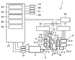
- FIG. 1 is a system configuration diagram of a drive control apparatus for a hybrid vehicle.
- FIG. 2 is a control block diagram for calculating the target operating point.
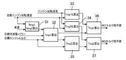
- FIG. 3 is a control block diagram for calculating the torque command value.
- FIG. 4 is a flowchart for engine target operating point calculation control.
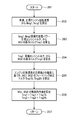
- FIG. 5 is a flowchart for calculating a torque command value.
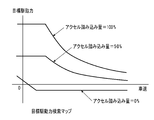
- FIG. 6 is a target driving force search map composed of the target driving force and the vehicle speed.
- FIG. 7 is a target charge / discharge power search table comprising target charge / discharge power and battery charge state detection means.
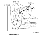
- FIG. 8 is a target engine operating point search map composed of engine torque and engine speed.
- FIG. 9 is a collinear diagram when the vehicle speed is changed at the same engine operating point.
- FIG. 1 is a system configuration diagram of a drive control apparatus for a hybrid vehicle.
- FIG. 2 is a control block diagram for calculating the target operating point.
- FIG. 3 is a control block diagram for
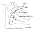
- FIG. 10 is a diagram showing the best line for engine efficiency and the best line for overall efficiency, which are composed of engine torque and engine speed.
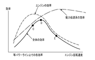
- FIG. 11 is a diagram showing each efficiency on the equal power line composed of the efficiency and the engine speed.
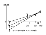
- FIG. 12 is a collinear diagram of each point (D, E, F) on the equal power line.
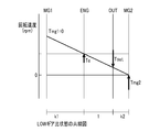
- FIG. 13 is a collinear diagram of the LOW gear ratio state.
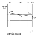
- FIG. 14 is a collinear diagram of the intermediate gear ratio state.
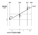
- FIG. 15 is a collinear diagram of the HIGH gear ratio state.
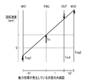
- FIG. 16 is a collinear diagram in a state where power circulation occurs.
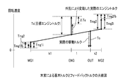
- FIG. 17 is a collinear diagram of basic torque and feedback torque.
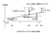
- FIG. 18 is a collinear diagram when feedback is provided only by MG1.
- reference numeral 1 denotes a hybrid vehicle drive control device (not shown), that is, a four-axis power input / output device to which the present invention is applied.
- the hybrid vehicle drive control device 1 is configured to drive and control a vehicle using an internal combustion engine (also referred to as “E / G” or “ENG”) 2 and an output from an electric motor.
- a drive system is connected to the output shaft 3 of the internal combustion engine 2 that generates a driving force by the combustion of fuel via a one-way clutch 4, and generates a driving force by electricity and generates electric energy by driving.
- Motor generator also referred to as “MG1” and “first electric motor” 5 and second motor generator (also referred to as “MG2” and “second electric motor”) 6 and drive wheels 7 of the hybrid vehicle.
- Drive shaft 8 output shaft 3, first motor generator 5, second motor generator 6, and first planetary gear (also referred to as “PG 1”) connected to the drive shaft 8, respectively.
- first motor generator 5, second motor generator 6, and first planetary gear also referred to as “PG 1” connected to the drive shaft 8, respectively.
- PG2 also referred to as “PG2”.
- PG2 second planetary gears
- the internal combustion engine 2 includes an air amount adjusting means 11 such as a throttle valve that adjusts an intake air amount corresponding to an accelerator opening (a depression amount of an accelerator pedal), and a fuel that supplies fuel corresponding to the intake air amount.
- a fuel supply means 12 such as an injection valve and an ignition means 13 such as an ignition device for igniting the fuel are provided.
- the combustion state of the fuel is controlled by the air amount adjusting means 11, the fuel supply means 12, and the ignition means 13, and a driving force is generated by the combustion of the fuel.
- the first planetary gear 9 includes a first planetary carrier (also referred to as “C1”) 9-1, a first ring gear 9-2, and a first sun gear 9-3. And an output gear 14 including a first pinion gear 9-4, an output gear 14 connected to the drive shaft 8 of the drive wheel 7, and a gear, a chain, and the like that connect the output gear 14 to the drive shaft 8.
- the second planetary gear 10 includes a second planetary carrier (also referred to as “C2”) 10-1, a second ring gear 10-2, and a second sun gear 10-3. And a second pinion gear 10-4.
- the first planetary carrier 9-1 of the first planetary gear 9 and the second sun gear 10-3 of the second planetary gear 10 are connected to the output shaft 3 of the internal combustion engine 2.
- the first ring gear 9-2 of the first planetary gear 9 and the second planetary carrier 10-1 of the second planetary gear 10 are coupled to communicate with the drive shaft 8. It connects to the output gear 14 which is a member.
- the first motor generator 5 includes a first motor rotor 5-1, a first motor stator 5-2, and a first motor rotor shaft 5-3
- the second motor generator 6 includes a second motor rotor. 6-1, a second motor stator 6-2, and a second motor rotor shaft 6-3.
- the first motor rotor 5-1 of the first motor generator 5 is connected to the first sun gear 9-3 of the first planetary gear 9, and the second ring of the second planetary gear 10 is connected.
- the second motor rotor 6-1 of the second motor generator 6 is connected to the gear 10-2. That is, in the hybrid vehicle, four elements including the internal combustion engine 2, the first motor generator 5, the second motor generator 6, and the output gear 14 are collinear (see FIGS.
- the differential gear mechanism 15 which is a gear mechanism connected so as to be in the order of the first motor generator 5, the output gear 14, and the second motor generator 6 is provided. Therefore, power is transferred between the internal combustion engine 2, the first motor generator 5, the second motor generator 6, and the drive shaft 8.
- first inverter 16 is connected to the first motor stator 5-2 of the first motor generator 5, and the second inverter 17 is connected to the second motor stator 6-2 of the second motor generator 6. .
- the first and second motor generators 5 and 6 are controlled by the first and second inverters 16 and 17, respectively.
- the power terminals of the first and second inverters 16 and 17 are connected to a battery 18 that is a power storage device.
- the hybrid vehicle drive control device 1 controls the drive of the vehicle using outputs from the internal combustion engine 2 and the first and second motor generators 5 and 6.
- the hybrid vehicle drive control device 1 includes the internal combustion engine 2 having the output shaft 3, the drive shaft 8 connected to the drive wheels 7, the first and second motor generators 5, 6
- the differential gear mechanism 15 having four rotating elements respectively connected to the first and second motor generators 5 and 6, the drive shaft 8, and the internal combustion engine 2, which are the plurality of motor generators, Accelerator opening degree detecting means 19 for detecting the accelerator opening degree, vehicle speed detecting means 20 for detecting the vehicle speed, battery charging state detecting means 21 for detecting the charging state of the battery 18, and the accelerator opening degree detecting means 19
- the target drive power setting for setting the target drive power based on the accelerator opening detected by the vehicle speed and the vehicle speed detected by the vehicle speed detection means 20 Stage 22, target charge / discharge power setting means 23 for setting a target charge / discharge power based on at least the charge state of the battery 18 detected by the battery charge state detection means 21, the target drive power setting means 22,
- a target engine power calculating means 24 for calculating a target engine power from the discharge power setting means 23; a target engine operating point
- Motor torque command value calculation means 26 for setting torque command values Tmg1, Tmg2 of the first and second motor generators 5, 6 as generators.
- the two-motor stator 6-2 is connected to a drive control unit 27 that is a control system of the drive control device 1 of the hybrid vehicle.
- the drive control unit 27 of the hybrid vehicle drive control device 1 includes an accelerator opening degree detection means 19, a vehicle speed detection means 20, a battery charge state detection means 21, and an engine rotation speed detection means 28. And.
- the accelerator opening detecting means 19 detects the accelerator opening that is the amount of depression of the accelerator pedal.
- the vehicle speed detection means 20 detects the vehicle speed (vehicle speed) of the hybrid vehicle.
- the battery charge state detection means 21 detects the state of charge SOC of the battery 18.
- the drive control unit 27 for calculating the target operating point includes, as shown in FIG. 1, the target drive power setting means 22, the target charge / discharge power setting means 23, the target engine power calculation means 24, The target engine operating point setting means 25 and the motor torque command value calculating means 26 are provided.
- the target charge / discharge power setting means 23 sets a target charge / discharge power based on at least the charge state SOC of the battery 18 detected by the battery charge state detection means 21.
- the target charge / discharge power is searched and set by the target charge / discharge power search map shown in FIG. 7 according to the battery state of charge SOC.
- the target engine power calculation means 24 calculates a target engine power from the target drive power set by the target drive power setting means 22 and the target charge / discharge power set by the target charge / discharge power setting means 23.
- the target engine power is obtained by subtracting the target charge / discharge power from the target drive power.
- the target engine operating point setting means 25 sets a target engine operating point from the target engine power and the overall system efficiency.
- the motor torque command value calculation means 26 sets torque command values Tmg1 and Tmg2 of the first and second motor generators 5 and 6, which are the plurality of motor generators.
- the drive control unit 27 for calculating the torque command value includes first to seventh calculation units 31 to 37 as shown in FIG.
- the first calculation unit 31 calculates the engine rotation speed based on the target engine rotation speed (see FIG. 2) calculated by the target engine operating point setting unit 25 and the vehicle speed (vehicle speed) from the vehicle speed detection unit 20. , The MG1 rotational speed Nmg1 of the first motor generator 5 and the MG2 rotational speed Nmg2 of the second motor generator 6 are calculated.
- the second calculation unit 32 includes the MG1 rotation speed Nmg1 and the MG2 rotation speed Nmg2 calculated by the first calculation unit 31, and the target engine torque (see FIG. 2) calculated by the target engine operating point setting unit 25.
- the basic torque Tmg1i of the first motor generator 5 is calculated.
- the third calculation unit 33 uses the engine rotation speed from the engine rotation speed detection unit 28 and the target engine torque (see FIG. 2) calculated by the target engine operating point setting unit 25 to perform the first motor.
- a feedback correction torque Tmg1fb of the generator 5 is calculated.
- the fourth calculation unit 34 uses the engine rotation speed from the engine rotation speed detection unit 28 and the target engine torque (see FIG. 2) calculated by the target engine operating point setting unit 25 to perform the second motor.
- a feedback correction torque Tmg2fb of the generator 6 is calculated.
- the fifth calculator 35 includes the basic torque Tmg1i of the first motor generator 5 from the second calculator 32 and the target engine torque (see FIG. 2) calculated by the target engine operating point setting means 25. Thus, the basic torque Tmg2i of the second motor generator 6 is calculated.
- the sixth calculation unit 36 uses the basic torque Tmg1i of the first motor generator 5 from the second calculation unit 32 and the feedback correction torque Tmg1fb of the first motor generator 5 from the third calculation unit 33.
- the torque command value Tmg1 of the first motor generator 5 is calculated.
- the seventh calculation unit 37 is based on the feedback correction torque Tmg2fb of the second motor generator 6 from the fourth calculation unit 34 and the basic torque Tmg2i of the second motor generator 6 from the fifth calculation unit 35. Then, a torque command value Tmg2 of the second motor generator 6 is calculated.
- the motor torque command value calculating means 26 includes a torque balance equation including a target engine torque obtained from the target engine operating point, and a power balance equation including the target charge / discharge power.
- a torque balance equation including a target engine torque obtained from the target engine operating point
- a power balance equation including the target charge / discharge power.
- a torque correction value (also referred to as “feedback correction torque Tmg2fb”) of the second motor generator 6 is calculated based on a deviation between an actual engine speed and the target engine speed, and the first motor
- the ratio of the feedback correction torque Tmg1fb that is the torque correction value of the generator 5 and the feedback correction torque Tmg2fb that is the torque correction value of the second motor generator 6 is set to a predetermined value based on the lever ratio of the drive control device 1 of the hybrid vehicle. The ratio is set so that To.
- the torque fluctuation of the internal combustion engine 2 is canceled using the torque balance formula that focuses on the torque change with the drive shaft 8 as a fulcrum, even if the torque fluctuation occurs in the internal combustion engine 2,
- the drive shaft torque can be prevented from being affected.
- the first and second motor generators 5 and 6, which are a plurality of motor generators when the battery 18 is charged and discharged can be controlled.
- the engine speed can be quickly converged to the target value by finely correcting the torque command values Tmg1 and Tmg2 of the first and second motor generators 5 and 6, which are a plurality of motor generators. Can do. Therefore, since the engine operating point can be combined with the target operating point, an appropriate operating state can be obtained.
- the four rotating elements of the differential gear mechanism 15 are connected to the rotating element connected to the first motor generator 5, the rotating element connected to the internal combustion engine 2, and the drive shaft 8 in order in the collinear diagram.
- a feedback correction torque T which is a torque correction value of the second motor generator 6 Is a value obtained by multiplying 1 + k2 is set to maintain the equal relationship G2fb. Therefore, when the differential gear mechanism 15 having the same four rotating elements and different lever ratios is configured, it can be suitably used.
- the four rotating elements of the differential gear mechanism 15 are connected to the rotating element connected to the first motor generator 5, the rotating element connected to the internal combustion engine 2, and the drive shaft 8 in order in the collinear diagram.
- the rotary elements connected to the second motor generator 6 are arranged in this order, and the lever ratios of these elements are set as k1: 1: k2 in the same order.
- the relationship between the feedback correction torque Tmg1fb that is the torque correction value of the second motor generator 6 and the feedback correction torque Tmg2fb that is the torque correction value of the second motor generator 6 is the feedback correction torque Tmg1fb that is the torque correction value of the first motor generator 5.
- the value obtained by multiplying k1 and the torque correction value of the second motor generator 6 Is a value obtained by multiplying 1 + k2 set the feedback gain to be equal to click correction torque Tmg2fb. Therefore, when the differential gear mechanism 15 having the same four rotating elements and different lever ratios is configured, it can be suitably used. Since the gain is set in advance, the calculation load in the feedback control of the control device can be kept extremely small.
- the target engine operating point (target engine speed, target engine torque) is calculated from the driver's accelerator operation amount and the vehicle speed, and the motor torque command value calculating motor shown in FIG.
- the target torque of the first motor generator 5 and the second motor generator 6 is calculated based on the target engine operating point.
- the accelerator opening degree detection signal from the accelerator opening degree detecting means 19 comprising an accelerator opening degree sensor and the vehicle speed comprising a vehicle speed sensor.
- step (102) a vehicle speed detection signal from the detection means 20 and a detection signal of the state of charge SOC of the battery 18 from the battery charge state detection means 21, that is, various signals used for control are taken in.
- step (103) which detects a target driving force from the target driving force detection map shown in FIG.
- step (103) calculates the target driving force according to the vehicle speed and the accelerator opening from the target driving force detection map shown in FIG.
- step (104) of calculating a target drive power by multiplying the target drive force calculated in the step (103) of detecting the target drive force from the target drive force detection map of FIG. 6 and the vehicle speed.
- step (104) the target driving power calculated in step (103) and the vehicle speed are multiplied to calculate a target driving power which is a power necessary for driving the vehicle with the target driving power.
- step (105) calculates the target charge / discharge amount from the target charge / discharge power search table disclosed in FIG. 7 in order to control the state of charge SOC of the battery 18 within the normal use range.
- step (105) when the state of charge SOC of the battery 18 is low, the charging power is increased to prevent overdischarge of the battery 18, and when the state of charge SOC of the battery 18 is high. Increase discharge power to prevent overcharge.
- step (106) is to calculate a target engine power that is a power to be output from the internal combustion engine 2 from the target drive power and the target charge / discharge power.
- the power to be output by the internal combustion engine 2 is a value obtained by adding (subtracting in the case of discharging) the power for charging the battery 18 to the power necessary for driving the vehicle.
- the target engine power is calculated by subtracting the target charge / discharge power from the target drive power.
- step (107) is to calculate the target engine power and the target engine operating point corresponding to the vehicle speed from the target engine operating point search map disclosed in FIG.
- the target engine operating point search map of FIG. 8 shows the power constituted by the differential gear mechanism 15 and the first and second motor generators 5 and 6 for the efficiency of the internal combustion engine 2 on an equal power line.
- a line that is selected and connected for each power at a point where the overall efficiency is improved in consideration of the efficiency of the transmission system is set as a target operating point line.
- a target operating point line is set for each vehicle speed. At this time, the set value may be obtained experimentally, or calculated from the efficiency of the internal combustion engine 2, the first motor generator 5, and the second motor generator 6. Note that the target operating point line is set to move to the high rotation side as the vehicle speed increases.
- the first motor generator 5 operates as an electric motor
- the second motor generator 6 operates as a generator.
- the efficiency of the transmission system decreases. Therefore, as shown at point C in FIG. 11, even if the efficiency of the internal combustion engine 2 is good, the efficiency of the power transmission system is lowered, and the overall efficiency is lowered.
- the rotational speed of the first motor generator 5 may be set to 0 or more as indicated by a point E in the alignment chart shown in FIG. Since the operating point moves in the direction in which the rotational speed of the internal combustion engine 2 increases, the efficiency of the internal combustion engine 2 greatly decreases even when the efficiency of the power transmission system is improved, as indicated by point E in FIG. Overall efficiency is reduced. Therefore, as shown in FIG. 11, the point with high efficiency as a whole is a point D between them, and if this point is set as the target operating point, the most efficient driving is possible.
- FIG. 10 shows the three operating points, point C, point D, and point E, on the target operating point search map. When the vehicle speed is high, the operating point at which the overall efficiency is the best is the engine efficiency. It turns out that it moves to the high rotation side from the best operating point.
- a step of calculating MG1 rotation speed Nmg1t of the first motor generator 5 and MG2 rotation speed Nmg2t of the second motor generator 6 ( 202).
- the drive shaft rotational speed No of the planetary gear is calculated from the vehicle speed.
- the MG1 rotational speed Nmg1t of the first motor generator 5 and the MG2 rotational speed Nmg2t of the second motor generator 6 when the engine rotational speed becomes the target engine rotational speed Net are calculated by the following equations.
- This formula can be obtained from the relationship between the rotational speeds of the planetary gears.
- k1 and k2 are values determined by the gear ratio of the planetary gear as will be described later.
- step (202) From the MG1 rotational speed Nmg1t of the first motor generator 5 and the MG2 rotational speed Nmg2t of the second motor generator 6 obtained in step (202), the target charge / discharge power Pbatt, and the target engine torque Tet.
- the process proceeds to step (203) for calculating the basic torque Tmg1i of the first motor generator 5.
- the basic torque Tmg1i of the first motor generator 5 is calculated by the following mathematical formula (3).
- This mathematical formula (3) is the following mathematical formula (4) representing the balance of torque input to the planetary gear, and the electric power generated or consumed by the first motor generator 5 and the second motor generator 6.
- Pbatt simultaneous input and output power
- the basic torque Tmg2i of the second motor generator 6 is calculated from the basic torque Tmg1i of the first motor generator 5 and the target engine torque.
- the process proceeds to step (204) for calculating.
- the basic torque Tmg2i of the second motor generator 6 is calculated by the following formula (6). This formula (6) is derived from the above formula (4).
- the step (205) of calculating the feedback correction torques Tmg1fb and Tmg2fb of the first and second motor generators 5 and 6 is performed. Transition.
- this step (205) in order to bring the engine speed close to the target, the deviation from the target value of the engine speed is multiplied by a predetermined feedback gain, and the first and second motor generators 5, 6 feedback correction torques Tmg1fb and Tmg2fb are calculated.
- the feedback gain used here has a ratio of Set to be. By doing this, the ratio of the feedback correction torque is Thus, even if the engine torque varies, the drive shaft torque can be prevented from varying.
- step (205) of calculating the feedback correction torques Tmg1fb and Tmg2fb of the first and second motor generators 5 and 6 the control torque command values for the first and second motor generators 5 and 6 are calculated.
- each feedback correction torque is added to each basic torque to calculate a control torque command value Tmg1 for the first and second motor generators 5 and 6.
- the battery 18 is output while outputting a target driving force even if the engine torque fluctuates due to disturbance. It is possible to set the charge / discharge to a value close to the target value.
- the embodiment of the present invention uses the rotation feedback torques of the first motor generator 5 and the second motor generator 6 for making the engine rotation speed close to the target rotation as the main configuration.
- a planetary gear that is calculated based on the deviation between the speed and the target engine rotational speed and that does not affect the drive shaft torque by the ratio of the feedback torques of the first motor generator 5 and the second motor generator 6.
- a predetermined ratio based on the ratio is set.
Landscapes
- Engineering & Computer Science (AREA)
- Transportation (AREA)
- Mechanical Engineering (AREA)
- Chemical & Material Sciences (AREA)
- Combustion & Propulsion (AREA)
- Automation & Control Theory (AREA)
- Physics & Mathematics (AREA)
- Mathematical Physics (AREA)
- Electric Propulsion And Braking For Vehicles (AREA)
- Hybrid Electric Vehicles (AREA)
Abstract
Description
これを「3軸式」と呼ぶこととする。
この従来技術では前記内燃機関の動作点を停止を含めた点に設定できるため燃費を向上することができる。
しかし、シリーズ方式ほどではないが、十分な駆動軸トルクを得るためには比較的大きなトルクを有する電動機が必要となるため、及びLOWギア比域で発電機と電動機との間での電力の受け渡し量が増加するため電気的損失が大きくなり、未だ改善の余地がある。
この点を解決する方法としては、特許第3578451号公報、特開2004一15982号公報に開示されるものや、本出願人による特開2002-281607号公報がある。
特開2002-281607号公報の方法は、4つの回転要素を有する差動歯車機構の各回転要素に、内燃機関の出力軸、第一のモータジェネレータ(以後「MG1」ともいう。)、第2のモータジェネレータ(以後「MG2」ともいう。)、及び駆動輪に接続される駆動軸を接続し、内燃機関の動力とMG1、MG2の動力を合成して駆動軸に出力するものである。
そして、共線図上で内側の回転要素に内燃機関の出力軸と駆動軸を配置し、共線図上で外側の回転要素にMG1(内燃機関側)とMG2(駆動軸側)を配置することにより、内燃機関から駆動軸へ伝達される動力のうちMG1及びMG2が受け持つ割合を少なくすることができるので、MG1、MG2を小型化できると共に駆動装置としての伝達効率を改善できる。
これを「4軸式」と呼ぶこととする。
また、特許第3578451号公報も上記方法と同様であるが、さらに5つ目の回転要素を有し、この回転要素の回転を停止させるブレーキを設ける方法も提案している。
上記の従来技術では特許第3050125号公報に開示されるように、車両に要求される駆動力と蓄電池の充電に要求される電力を加算して内燃機関が出力すべきパワーを算出し、そのパワーとなるトルクと回転速度の組み合わせの中からできるだけ効率が良いポイントを算出して目標エンジン動作点としている。
そして内燃機関の動作点が目標動作点となるようにMG1を制御してエンジン回転速度を制御している。
しかし、「4軸式」の場合には、駆動軸とMG2とが別の軸となり、MG2のトルクもトルクバランスに影響してエンジン回転速度制御に影響するため、上記「3軸式」の制御方法は使えないという不都合がある。
また、「4軸式」である上記特開2004-15982では、バッテリヘの充放電の無い状態で走行する場合のMG1、MG2のトルクをトルクバランス式から算出し、回転速度をフィードバック制御してエンジン回転速度と駆動力を制御する方法が開示されている。
しかし、バッテリヘの充放電がある場合や、エンジントルクが変動した場合については言及していない。
更に、上記の特許文献1のものは、内燃機関と複数のモータジェネレータを備えたハイブリッドシステムにおいて、内燃機関の動作点に関してエンジン回転速度を高く設定するものであり、内燃機関の制御技術が開示されている。
このとき、上記の特許文献1における複数のモータジェネレータの制御は不明であり、さらに、バッテリとの充放電を行う場合の複数のモータジェネレータの制御は不明である。
なお、制御に際しては、内燃機関と複数のモータジェネレータを機械的に作動連結して、内燃機関の動作点を目標値に維持しながら複数のモータジェネレータを互いに関連させてトルクバランスをとって制御する必要があり、さらに、バッテリとの充放電を行う場合には、電力収支もバランスさせる必要がある。
そして、それらを両立するように制御する必要がある。
また、複数のモータジェネレータを互いに関連させてトルクバランスをとって制御する際に、フィードバック制御を行っても、その制御内容によっては、内燃機関のトルク変動が駆動トルクに影響を及ぼしてしまうという不都合がある。
従って、駆動軸を支点としてトルクの変化に注目したトルクバランス式を用いて、内燃機関のトルク変動を打ち消しているので、内燃機関にトルク変動が生じてもそれを駆動軸トルクに影響を与えないようにできる。
また、バッテリヘの充放電がある場合の複数のモータジェネレータの制御を行うことができる。
更に、内燃機関の動作点に配慮し、目標とする駆動力確保と目標とする充放電の確保とを両立することができる。
更にまた、複数のモータジェネレータの前記トルク指令値をそれぞれ細かく補正することによって、速やかに、エンジン回転速度を目標値に収束させることができる。
また、エンジン動作点を目標とする動作点に併せることができるので、適切な運転状態とすることができる。
図1において、1は図示しないハイブリッド車両の駆動制御装置、つまり、本発明が適用される4軸式の動力入出力装置である。
前記ハイブリッド車両の駆動制御装置1は、図1に示す如く、内燃機関(「E/G」、「ENG」とも記載する。)2と電動機からの出力を用いて車両を駆動制御するために、駆動系として、燃料の燃焼により駆動力を発生させる内燃機関2の出力軸3と、ワンウェイクラッチ4を介して接続され、かつ、電気により駆動力を発生するとともに駆動により電気エネルギを発生する第一のモータジェネレータ(「MG1」、「第1電動機」ともいう。)5及び第二のモータジェネレータ(「MG2」、「第2電動機」ともいう。)6と、ハイブリッド車両の駆動輪7に接続される駆動軸8と、出力軸3と、第一のモータジェネレータ5と、第二のモータジェネレータ6と、駆動軸8にそれぞれ連結された第1プラネタリギア(「PG1」とも記載する。)9及び第2プラネタリギア(「PG2」とも記載する。)10とを備えている。
前記内燃機関2は、空気量調整手段11と燃料供給手段12と着火手段13とにより燃料の燃焼状態を制御され、燃料の燃焼により駆動力を発生する。
また、前記第2プラネタリギア10は、図1に示す如く、第2プラネタリキャリア(「C2」とも記載する。)10-1と、第2リングギア10-2と、第2サンギア10-3と、第2ピニオンギヤ10-4とを有している。
そして、図1に示す如く、前記第1プラネタリギア9の第1プラネタリキャリア9-1と前記第2プラネタリギア10の第2サンギア10-3とを結合して内燃機関2の出力軸3に接続する。
また、図1に示す如く、前記第1プラネタリギア9の第1リングギア9-2と前記第2プラネタリギア10の第2プラネタリキャリア10-1とを結合して前記駆動軸8に連絡する出力部材である出力ギア14に接続する。
そして、図1に示す如く、前記第1プラネタリギア9の第1サンギア9-3に前記第一のモータジェネレータ5の第1モータロータ5-1を接続し、前記第2プラネタリギア10の第2リングギア10-2に前記第二のモータジェネレータ6の第2モータロータ6-1を接続する。
つまり、前記ハイブリッド車両は、前記内燃機関2と前記第一のモータジェネレータ5と前記第二のモータジェネレータ6と前記出力ギア14とから構成される4つの要素を、共線図(図9及び図10参照。)上で、前記第一のモータジェネレータ5、前記出力ギア14、前記第二のモータジェネレータ6の順になるように連結した歯車機構である前記差動歯車機構15を備えている。
従って、前記内燃機関2と前記第一のモータジェネレータ5と前記第二のモータジェネレータ6と前記駆動軸8との間で動力の授受が行われる。
そして、これらの第1、第2インバータ16、17により前記第一及び第二のモータジェネレータ5、6を夫々制御する。
また、前記第1、第2インバータ16、17の電源端子は蓄電装置であるバッテリ18に夫々接続する。
このとき、前記内燃機関2の空気量調整手段11や燃料供給手段12、着火手段13と、前記第一のモータジェネレータ5の第1モータステータ5-2と、前記第二のモータジェネレータ6の第2モータステータ6-2とは、前記ハイブリッド車両の駆動制御装置1の制御系である駆動制御部27に接続されている。
このハイブリッド車両の駆動制御装置1の駆動制御部27は、図1に示す如く、アクセル開度検出手段19と、車両速度検出手段20と、バッテリ充電状態検出手段21と、エンジン回転速度検出手段28とを備えている。
前記アクセル開度検出手段19は、アクセルペダルの踏み込み量であるアクセル開度を検出する。
前記車両速度検出手段20は、ハイブリッド車両の車両速度(車速)を検出する。
前記バッテリ充電状態検出手段21は、前記バッテリ18の充電状態SOCを検出する。
つまり、前記目標駆動パワー設定手段22は、図2に示す如く、目標駆動力算出部29と目標駆動パワー算出部30とを有し、前記目標駆動力算出部29は、前記アクセル開度検出手段19により検出されたアクセル開度と前記車両速度検出手段20により検出された車両速度とに応じて、図6に示す目標駆動力検索マップにより目標駆動力を設定する。
このとき、「アクセル開度=0」での高車速域は、エンジンブレーキ相当の減速方向の駆動力となるように負の値に設定し、車速が低い領域では、クリープ走行ができるように正の値としている。
また、前記目標駆動パワー算出部30は、前記目標駆動力算出部29にて設定された目標駆動力と前記車両速度検出手段20により検出された車両速度とを乗算して、目標駆動力で車両を駆動するのに必要な目標駆動パワーを算出する。
この実施例においては、バッテリ充電状態SOCに応じて、目標充放電パワーを、図7に示す目標充放電パワー検索マップにより検索して設定する。
この実施例においては、目標駆動パワーから目標充放電パワーを減算することにより、目標エンジンパワーを得る。
前記第2算出部32は、前記第1算出部31によって算出されたMG1回転速度Nmg1及びMG2回転速度Nmg2と前記目標エンジン動作点設定手段25により演算された目標エンジントルク(図2参照。)とによって、前記第一のモータジェネレータ5の基本トルクTmg1iを算出する。
前記第3算出部33は、前記エンジン回転速度検出手段28からのエンジン回転速度と前記目標エンジン動作点設定手段25により演算された目標エンジントルク(図2参照。)とによって、前記第一のモータジェネレータ5のフィードバック補正トルクTmg1fbを算出する。
前記第4算出部34は、前記エンジン回転速度検出手段28からのエンジン回転速度と前記目標エンジン動作点設定手段25により演算された目標エンジントルク(図2参照。)とによって、前記第二のモータジェネレータ6のフィードバック補正トルクTmg2fbを算出する。
前記第5算出部35は、前記第2算出部32からの前記第一のモータジェネレータ5の基本トルクTmg1iと前記目標エンジン動作点設定手段25により演算された目標エンジントルク(図2参照。)とによって、前記第二のモータジェネレータ6の基本トルクTmg2iを算出する。
前記第6算出部36は、前記第2算出部32からの前記第一のモータジェネレータ5の基本トルクTmg1iと前記第3算出部33からの前記第一のモータジェネレータ5のフィードバック補正トルクTmg1fbとによって、前記第一のモータジェネレータ5のトルク指令値Tmg1を算出する。
前記第7算出部37は、前記第4算出部34からの前記第二のモータジェネレータ6のフィードバック補正トルクTmg2fbと前記第5算出部35からの前記第二のモータジェネレータ6の基本トルクTmg2iとによって、前記第二のモータジェネレータ6のトルク指令値Tmg2を算出する。
さすれば、前記駆動軸8を支点としてトルクの変化に注目したトルクバランス式を用いて、前記内燃機関2のトルク変動を打ち消しているので、前記内燃機関2にトルク変動が生じてもそれを駆動軸トルクに影響を与えないようにできる。
また、前記バッテリ18ヘの充放電がある場合の複数のモータジェネレータである前記第一及び第二のモータジェネレータ5、6の制御を行うことができる。
更に、前記内燃機関2の動作点に配慮し、目標とする駆動力確保と目標とする充放電の確保とを両立することができる。
更にまた、複数のモータジェネレータである前記第一及び第二のモータジェネレータ5、6の前記トルク指令値Tmg1、Tmg2をそれぞれ細かく補正することによって、速やかに、エンジン回転速度を目標値に収束させることができる。
従って、エンジン動作点を目標とする動作点に併せることができるので、適切な運転状態とすることができる。
従って、同様の4つの回転要素を持つレバー比が異なる前記差動歯車機構15を構成する場合、好適に用いることができる。
従って、同様の4つの回転要素を持つレバー比が異なる前記差動歯車機構15を構成する場合、好適に用いることができる。
予めゲインを設定しているので、制御装置のフィードバック制御における演算負荷を極めて小さく抑えることができる。
図4のエンジン目標動作点算出制御用のフローチャートでは運転者のアクセル操作量と車速から目標エンジン動作点(目標エンジン回転速度、目標エンジントルク)を演算し、図5のモータトルク指令値算出用のフローチャートでは目標エンジン動作点に基づいて前記第一のモータジェネレータ5と前記第二のモータジェネレータ6との目標トルクを演算する。
そして、図6に示す目標駆動力検出マップから目標駆動力を検出するステップ(103)に移行する。
このステップ(103)は、図6に示す目標駆動力検出マップから車速とアクセル開度に応じた目標駆動力を算出するものである。
このとき、「アクセル開度=0」の場合、高車速域ではエンジンブレーキ相当の減速方向の駆動力となるように負の値に設定し、車速が低い領域では、クリープ走行ができるように正の値とする。
このステップ(104)は、ステップ(103)にて算出した目標駆動力と車速とを乗算し、目標駆動力で車両を駆動するのに必要なパワーである目標駆動パワーを算出するものである。
このステップ(105)は、前記バッテリ18の充電状態SOCを通常使用範囲内に制御するために、目標とする充放電量を図7に開示する目標充放電パワー検索テーブルから算出するものである。
このとき、ステップ(105)において、前記バッテリ18の充電状態SOCが低い場合には、充電パワーを大きくして前記バッテリ18の過放電を防止し、前記バッテリ18の充電状態SOCが高い場合には、放電パワーを大きくして過充電を防止する。
このステップ(106)は、目標駆動パワーと目標充放電パワーとから前記内燃機関2が出力すべきパワーである目標エンジンパワーを算出するものである。
このとき、前記内燃機関2が出力すべきパワーは、車両の駆動に必要なパワーに前記バッテリ18を充電するパワーを加算(放電の場合は減算)した値となる。
ここでは、充電側の負の値として取り扱っているので、目標駆動パワーから目標充放電パワーを減算して、目標エンジンパワーを算出する。
このステップ(107)は、図8に開示する目標エンジン動作点検索マップから、目標エンジンパワーと車速に応じた目標エンジン動作点とを算出するものである。
そして目標動作点ラインは各車速毎に設定する。
このとき、設定値は実験的に求めてもよいし、前記内燃機関2、前記第一のモータジェネレータ5、前記第二のモータジェネレータ6の効率から計算して求めてもよい。
なお、目標動作点ラインは車速が高くなるに連れて高回転側に移動する設定としている。
車速によらず同一のエンジン動作点を目標エンジン動作点とした場合、図9に示す如く、車速が低い場合には前記第一のモータジェネレータ5の回転速度は正となり、前記第一のモータジェネレータ5が発電機、前記第二のモータジェネレータ6が電動機となる(点A参照。)。
そして、車速が高くなるに連れて前記第一のモータジェネレータ5の回転速度は0に近づき(点B参照。)、さらに車遠が高くなると前記第一のモータジェネレータ5の回転速度は負となり、この状態になると前記第一のモータジェネレータ5は電動機として作動するとともに、前記第二のモータジェネレータ6は発電機として作動する(点C参照。)。
車速が低い場合(点A、Bの状態)にパワーの循環は起きないので、目標動作点は、図8の車速=40km/hの目標動作点ラインのように、概ねエンジン効率の良いポイントに近いものとなる。
しかし、車速が高い場合(点Cの状態)になると、前記第一のモータジェネレータ5は電動機として作動するとともに、前記第二のモータジェネレータ6は発電機として作動し、パワー循環が発生するため動力伝達系の効率が低下する。
従って、図11の点Cに示すように、前記内燃機関2の効率が良くても動力伝達系の効率が低下するため、全体としての効率が低下してしまう。
そこで、高車速域でパワー循環が発生しないようにするには、図12に示す共線図の点Eのように前記第一のモータジェネレータ5の回転速度を0以上にすればよいが、そうすると前記内燃機関2の回転速度が高くなる方へ動作点が移動するので、図11の点Eに示すように、動力伝達系の効率が良くなっても前記内燃機関2の効率が大きく低下するので全体としての効率は低下してしまう。
従って、図11に示すように全体としての効率が良いポイントは両者の間の点Dとなり、このポイントを目標動作点とすれば最も効率のよい運転が可能となる。
以上、点C、点D、点Eの3つの動作点を目標動作点検索マップ上に表したのが図10であり、車速が高い場合には全体効率が最良となる動作点がエンジン効率が最良となる動作点より高回転側に移動することが判る。
このステップ(202)においては、車速から遊星ギアの駆動軸回転速度Noを算出する。
そして、エンジン回転速度が目標エンジン回転速度Netとなった場合の前記第一のモータジェネレータ5のMG1回転速度Nmg1tと前記第二のモータジェネレータ6のMG2回転速度Nmg2tを以下の式により算出する。
この数式は遊星ギアの回転速度の関係から求められる。


ここで、k1、k2は後述するように遊星ギアのギア比により定まる値である。
このステップ(203)においては、前記第一のモータジェネレータ5の基本トルクTmg1iを以下の数式(3)により算出する。



このステップ(204)においては、前記第二のモータジェネレータ6の基本トルクTmg2iを以下の数式(6)により算出する。

この数式(6)は上記の数式(4)から導き出したものである。
このステップ(205)においては、エンジン回転速度を目標に近づけるために、エンジン回転速度の目標値との偏差に予め設定した所定のフィードバックゲインを乗算し、前記第一及び第二のモータジェネレータ5、6のフィードバック補正トルクTmg1fb、Tmg2fbを算出するものである。
ここで用いるフィードバックゲインは、その比が

となるように設定しておく。
こうすることによりフィードバック補正トルクの比が、

となり、エンジントルクが変動しても駆動軸トルクが変動しないようにすることができる。
比較のため、仮にエンジン回転速度を目標値に近づけるために前記第一のモータジェネレータ5のみフィードバックを行なった場合を想定する。
この場合の共線図を図18に示す。
トルクの変化量に着目してトルクバランス式に基づきエンジントルクが目標トルクに対してΔTeだけ変化した場合のMG1トルクのフィードバック補正トルクTmg1fbを計算すると、

となる。
但し、ΔTeは不明であるため、実際には前述のようにMG1トルクのフィードバック補正トルクTmg1fbは回転速度フィードバックにより算出している。
そして、駆動軸トルクの変化量ΔToは

となり、エンジントルクの変化により駆動軸トルクが変化してしまうことが判る。
これに対し、本発明のように前記第一のモータジェネレータ5のフィードバック補正に加えて前記第二のモータジェネレータ6もフィードバック補正する場合について説明する。
この場合の共線図を図17に示す。
前記駆動軸8を支点としてトルクの変化最に着目したトルクバランス式は、

となり、駆動軸トルクの変化量は各トルクの変化量の和に等しいので、

となり、駆動軸トルクの変化量が無い場合にはΔTo=0となるので、

となり、上記の数式(11)と数式(13)を解くと前述の数式(8)となり、この関係が成立すればエンジントルクが変化しても駆動軸トルクは変化しないことが判る。
このステップ(206)においては、各フィードバック補正トルクを各基本トルクに加算して、前記第一及び第二のモータジェネレータ5、6の制御用トルク指令値Tmg1を算出するものである。
そして、この制御用トルク指令値Tmg1に従って前記第一及び第二のモータジェネレータ5、6を制御することにより、エンジントルクが外乱によって変動しても目標とする駆動力を出力しつつ、前記バッテリ18ヘの充放電を目標値に近い値とすることができる。
ここで、遊星ギアのギア比により定まる値k1、k2は下記のように定義される。
k1=ZR1/ZS1
k2=ZS2/ZR2
ZS1:PG1サンギア歯数
ZR1:PG1リングギア歯数
ZS2:PG2サンギア歯数
ZR2:PG2リングギア歯数
次に各動作状態について共線図を用いて説明する。
なお、回転速度は前記内燃機関2の回転方向を正方向とし、各軸に入出力されるトルクは前記内燃機関2のトルクと同じ向きのトルクが入力される方向を正として定義する。
従って駆動軸トルクが正の場合は車両を後方へ駆動しようとするトルクが出力されている状態(前進時であれば減速、後進時であれば駆動)であり、駆動軸トルクが負の場合は車両を前方へ駆動しようとするトルクが出力されている状態(前進時であれば駆動、後進時であれば減速)である。
モータによる発電や力行(動力を車輪(駆動輪)に伝えて加速、または上り勾配で均衡速度を保つこと)を行う場合、インバータやモータでの発熱による損失が発生するため電気エネルギと機械的エネルギとの間で変換を行う場合の効率は100%ではないが、説明を簡単にするため損失は無いと仮定して説明する。
現実として損失を考慮する場合には、損失により失われるエネルギの分だけ余分に発電するように制御すればよい。
(1)LOWギア比状態
内燃機関により走行し、前記第二のモータジェネレータ6の回転速度が0の状態である。
この時の共線図を図13に示す。
前記第二のモータジェネレータ6の回転速度は0であるため電力は消費しない。
従って、蓄電池への充放電が無い場合には、前記第一のモータジェネレータ5で発電を行う必要はないため、前記第一のモータジェネレータ5のトルク指令値Tmg1は0となる。
また、エンジン回転速度と駆動軸回転速度の比は(1+k2)/k2となる。
(2)中間ギア比状態
前記内燃機関2により走行し、前記第一のモータジェネレータ5及び前記第二のモータジェネレータ6の回転速度が正の状態である。
この時の共線図を図14に示す。
この場合、蓄電池への充放電が無い場合、前記第一のモータジェネレータ5は回生となり、この回生電力を用いて前記第二のモータジェネレータ6を力行させる。
(3)HIGHギア比状態
前記内燃機関2により走行し、前記第一のモータジェネレータ5の回転速度が0の状態である。
この時の共線図を図15に示す。
前記第一のモータジェネレータ5の回転速度は0であるため回生はしない。
従って、蓄電池への充放電が無い場合には、前記第二のモータジェネレータ6での力行や回生は行わず、前記第二のモータジェネレータ6のトルク指令値Tmg2は0となる。
またエンジン回転速度と駆動軸回転速度の比は
k1/(1+k1)
となる。
(4)動力循環が発生している状態
HIGHギア比状態よりさらに車速が高い状態では、前記第一のモータジェネレータ5が逆回転する状態となる。
この状態では前記第一のモータジェネレータ5は力行となり電力を消費する。
従って蓄電池への充放電がない場合には前記第二のモータジェネレータ6(5)が回生となり発電を行う。
そして、この発明の実施例は、MG2フィードバックトルク=k1/(1+k2)*MG1フィードバックトルク、となるように制御する。
また、MG2フィードバックゲイン=k1/(1+k2)*MG1フィードバックゲイン、となるようにフィードバックゲインを設定する。
これにより、エンジン出力トルクが目標トルクに対して変化しても、駆動力が変動しないようにできるという効果を奏する。
2 内燃機関(「E/G」、「ENG」とも記載する。)
3 出力軸
4 ワンウェイクラッチ
5 第一のモータジェネレータ(「MG1」、「第1電動機」ともいう。)
6 第二のモータジェネレータ(「MG2」、「第2電動機」ともいう。)
7 駆動輪
8 駆動軸
9 第1プラネタリギア(「PG1」とも記載する。)
10 第2プラネタリギア(「PG2」とも記載する。)
11 空気量調整手段
12 燃料供給手段
13 着火手段
14 出力ギア
15 差動歯車機構
16 第1インバータ
17 第2インバータ
18 バッテリ
19 アクセル開度検出手段
20 車両速度検出手段
21 バッテリ充電状態検出手段
22 目標駆動パワー設定手段
23 目標充放電パワー設定手段
24 目標エンジンパワー算出手段
25 目標エンジン動作点設定手段
26 モータトルク指令値演算手段
27 駆動制御部
28 エンジン回転速度検出手段
29 目標駆動力算出部
30 目標駆動パワー算出部
31~37 第1~第7算出部
Claims (3)
- 出力軸を有する内燃機関と、駆動輪に接続される駆動軸と、第一と第二のモータジェネレータと、それら複数のモータジェネレータと駆動軸と内燃機関とにそれぞれ連結された4つの回転要素を有する差動歯車機構と、アクセル開度を検出するアクセル開度検出手段と、車両速度を検出する車両速度検出手段と、バッテリの充電状態を検出するバッテリ充電状態検出手段と、前記アクセル開度検出手段により検出されたアクセル開度と前記車両速度検出手段により検出された車両速度とに基づいて目標駆動パワーを設定する目標駆動パワー設定手段と、少なくとも前記バッテリ充電状態検出手段により検出されたバッテリの充電状態に基づいて目標充放電パワーを設定する目標充放電パワー設定手段と、前記目標駆動パワー設定手段と目標充放電パワー設定手段とから目標エンジンパワーを算出する目標エンジンパワー算出手段と、目標エンジンパワーとシステム全体効率とから目標エンジン動作点を設定する目標エンジン動作点設定手段と、前記複数のモータジェネレータのそれぞれのトルク指令値を設定するモータトルク指令値演算手段とを備えるハイブリッド車両の駆動制御装置であって、前記モータトルク指令値演算手段は、前記目標エンジン動作点から求められる目標エンジントルクを含むトルクバランス式と前記目標充放電パワーを含む電力バランス式とを用いて前記複数のモータジェネレータのそれぞれのトルク指令値を算出するとともに、前記目標エンジン動作点から求められる目標エンジン回転速度に実際のエンジン回転速度を収束させるように前記複数のモータジェネレータの前記トルク指令値にそれぞれのフィードバック補正を行うことを可能とするハイブリッド車両の駆動制御装置において、前記モータトルク指令値演算手段は、前記フィードバック補正を行う際、前記複数のモータジェネレータの第一のモータジェネレータのトルク補正値と第二のモータジェネレータのトルク補正値とを、実際のエンジン回転速度と前記目標エンジン回転速度との偏差に基づいて算出するとともに、これら第一のモータジェネレータのトルク補正値と第二のモータジェネレータのトルク補正値との比を、前記ハイブリッド車両の駆動制御装置のレバー比に基づく所定の比となるよう設定することを特徴とするハイブリッド車両の駆動制御装置。
- 前記差動歯車機構の前記4つの回転要素を、共線図において順に第一のモータジェネレータに連結された回転要素、内燃機関に連結された回転要素、駆動軸に連結された回転要素、第二のモータジェネレータに連結された回転要素の順に並ぶとともに、それらの要素間の相互のレバー比を同順にk1:1:k2として設け、第一のモータジェネレータのトルク補正値と第二のモータジェネレータのトルク補正値とを、第一のモータジェネレータのトルク補正値にk1を乗じた値と第二のモータジェネレータのトルク補正値に1+k2を乗じた値とが等しくなる関係を維持するように設定することを特徴とする請求項1に記載のハイブリッド車両の駆動制御装置。
- 前記差動歯車機構の前記4つの回転要素を、共線図において順に第一のモータジェネレータに連結された回転要素、内燃機関に連結された回転要素、駆動軸に連結された回転要素、第二のモータジェネレータに連結された回転要素の順に並ぶとともに、それらの要素問の相互のレバー比を同順にk1:1:k2として設け、第一のモータジェネレータのトルク補正値と第二のモータジェネレータのトルク補正値との関係が第一のモータジェネレータのトルク補正値にk1を乗じた値と第二のモータジェネレータのトルク補正値に1+k2を乗じた値とが等しくなるようにフィードバックゲインを設定することを特徴とする請求項1に記載のハイブリッド車両の駆動制御装置。
Priority Applications (5)
| Application Number | Priority Date | Filing Date | Title |
|---|---|---|---|
| DE112011104798T DE112011104798T5 (de) | 2011-01-31 | 2011-01-31 | Antriebssteuervorrichtung für Hybridfahrzeug |
| JP2012555587A JP5818231B2 (ja) | 2011-01-31 | 2011-01-31 | ハイブリッド車両の駆動制御装置 |
| US13/981,801 US20140046527A1 (en) | 2011-01-31 | 2011-01-31 | Drive control apparatus for hybrid vehicle |
| CN201180066481.0A CN103338998B (zh) | 2011-01-31 | 2011-01-31 | 混合动力车辆的驱动控制装置 |
| PCT/JP2011/051908 WO2012104960A1 (ja) | 2011-01-31 | 2011-01-31 | ハイブリッド車両の駆動制御装置 |
Applications Claiming Priority (1)
| Application Number | Priority Date | Filing Date | Title |
|---|---|---|---|
| PCT/JP2011/051908 WO2012104960A1 (ja) | 2011-01-31 | 2011-01-31 | ハイブリッド車両の駆動制御装置 |
Publications (1)
| Publication Number | Publication Date |
|---|---|
| WO2012104960A1 true WO2012104960A1 (ja) | 2012-08-09 |
Family
ID=46602208
Family Applications (1)
| Application Number | Title | Priority Date | Filing Date |
|---|---|---|---|
| PCT/JP2011/051908 Ceased WO2012104960A1 (ja) | 2011-01-31 | 2011-01-31 | ハイブリッド車両の駆動制御装置 |
Country Status (5)
| Country | Link |
|---|---|
| US (1) | US20140046527A1 (ja) |
| JP (1) | JP5818231B2 (ja) |
| CN (1) | CN103338998B (ja) |
| DE (1) | DE112011104798T5 (ja) |
| WO (1) | WO2012104960A1 (ja) |
Cited By (2)
| Publication number | Priority date | Publication date | Assignee | Title |
|---|---|---|---|---|
| JP2014162234A (ja) * | 2013-02-21 | 2014-09-08 | Denso Corp | ハイブリッド車の制御装置 |
| CN104044576A (zh) * | 2013-03-12 | 2014-09-17 | 铃木株式会社 | 混合动力车辆 |
Families Citing this family (12)
| Publication number | Priority date | Publication date | Assignee | Title |
|---|---|---|---|---|
| KR101500397B1 (ko) * | 2013-12-24 | 2015-03-19 | 현대자동차 주식회사 | 전기 차량의 제어 방법 |
| CN103818375B (zh) * | 2014-03-05 | 2016-03-30 | 东风襄阳旅行车有限公司 | 单轴并联式混合动力汽车发动机转矩估算校正方法 |
| SE539232C2 (sv) | 2014-09-29 | 2017-05-23 | Scania Cv Ab | Förfarande för att styra en hybriddrivlina, fordon med en sådan hybriddrivlina, dator-program för att styra en sådan hybriddrivlina, samt en datorprogramprodukt innefattande programkod |
| SE540406C2 (sv) | 2014-09-29 | 2018-09-11 | Scania Cv Ab | Förfarande för att styra en hybriddrivlina, fordon med en sådan hybriddrivlina, datorprogram för att styra en sådan hybriddrivlina, samt en datorprogramprodukt innefattande programkod |
| SE539295C2 (sv) * | 2014-09-29 | 2017-06-20 | Scania Cv Ab | Hybriddrivlina innefattande en rangeväxel och ett fordon meden sådan hybriddrivlina |
| WO2016053171A1 (en) | 2014-09-29 | 2016-04-07 | Scania Cv Ab | Hybrid powertrain, method for controlling such a hybrid powertrain, vehicle comprising such a hybrid powertrain, computer program for controlling such a hybrid power- train, and a computer program product comprising program code |
| SE539293C2 (sv) | 2014-09-29 | 2017-06-20 | Scania Cv Ab | Förfarande för att styra en hybriddrivlina, fordon som innefattar en sådan hybriddrivlina, datorprogram för att styra ensådan hybriddrivlina, samt en datorprogramprodukt innefatta nde programkod |
| SE539294C2 (sv) | 2014-09-29 | 2017-06-20 | Scania Cv Ab | Förfarande för att styra en hybriddrivlina, fordon som innefattar en sådan hybriddrivlina, datorprogram för att styra ensådan hybriddrivlina, samt en datorprogramprodukt innefatta nde programkod |
| JP6897577B2 (ja) * | 2018-01-10 | 2021-06-30 | トヨタ自動車株式会社 | 車両におけるハイブリッドシステムの制御装置 |
| KR102529518B1 (ko) * | 2018-06-22 | 2023-05-04 | 현대자동차주식회사 | 친환경자동차의 구동 토크 지령 생성 장치 및 방법 |
| JP2021188704A (ja) * | 2020-06-02 | 2021-12-13 | トヨタ自動車株式会社 | 係合機構の制御装置 |
| DE102021206424B4 (de) * | 2021-06-22 | 2023-02-16 | Rolls-Royce Solutions GmbH | Regeleinrichtung zur Regelung einer eine Brennkraftmaschine und einen mit der Brennkraftmaschine antriebswirkverbundenen Generator umfassenden Leistungsanordnung, Regelanordnung mit einer solchen Regeleinrichtung, Leistungsanordnung und Verfahren zur Regelung einer Leistungsanordnung |
Citations (5)
| Publication number | Priority date | Publication date | Assignee | Title |
|---|---|---|---|---|
| JP2004262275A (ja) * | 2003-02-28 | 2004-09-24 | Nissan Motor Co Ltd | ハイブリッド車両の制御装置 |
| JP2006050704A (ja) * | 2004-08-02 | 2006-02-16 | Nissan Motor Co Ltd | 電動力伝達装置 |
| JP2007022483A (ja) * | 2005-07-21 | 2007-02-01 | Nissan Motor Co Ltd | ハイブリッド変速機のモード遷移制御方法 |
| JP2007296937A (ja) * | 2006-04-28 | 2007-11-15 | Suzuki Motor Corp | ハイブリッド車両の制御装置 |
| JP2008012992A (ja) * | 2006-07-04 | 2008-01-24 | Suzuki Motor Corp | ハイブリッド車両の駆動制御装置 |
Family Cites Families (19)
| Publication number | Priority date | Publication date | Assignee | Title |
|---|---|---|---|---|
| IL49201A (en) * | 1976-03-12 | 1980-02-29 | Scientific Res Foundation | Vehicle drive system including a flywheel and selectable coupling means |
| JP2870822B2 (ja) | 1989-07-17 | 1999-03-17 | 三菱電機株式会社 | シリコンとガラスとの接合方法 |
| JP2621491B2 (ja) | 1989-07-18 | 1997-06-18 | 日立化成工業株式会社 | シリカガラスの製造法 |
| JPH0350138A (ja) | 1989-07-18 | 1991-03-04 | Canon Inc | 光学ガラス |
| JPH0397572A (ja) | 1989-09-11 | 1991-04-23 | Mitsubishi Electric Corp | サーマルヘッド駆動装置 |
| JP3050125B2 (ja) * | 1996-05-20 | 2000-06-12 | トヨタ自動車株式会社 | 動力出力装置および動力出力装置の制御方法 |
| US6208497B1 (en) * | 1997-06-26 | 2001-03-27 | Venture Scientifics, Llc | System and method for servo control of nonlinear electromagnetic actuators |
| US6942469B2 (en) * | 1997-06-26 | 2005-09-13 | Crystal Investments, Inc. | Solenoid cassette pump with servo controlled volume detection |
| JP3449239B2 (ja) * | 1998-09-22 | 2003-09-22 | 日産自動車株式会社 | ハイブリッド車両の制御装置 |
| JP4050002B2 (ja) * | 2001-02-28 | 2008-02-20 | ジヤトコ株式会社 | パラレルハイブリッド車両 |
| JP3852562B2 (ja) | 2001-03-21 | 2006-11-29 | スズキ株式会社 | 動力入出力装置 |
| JP2004015982A (ja) | 2002-06-11 | 2004-01-15 | Nissan Motor Co Ltd | ハイブリッド変速機の変速制御装置 |
| JP3843966B2 (ja) * | 2003-06-05 | 2006-11-08 | アイシン・エィ・ダブリュ株式会社 | ハイブリッド型車両駆動制御装置、ハイブリッド型車両駆動制御方法及びそのプログラム |
| JP4239724B2 (ja) * | 2003-07-29 | 2009-03-18 | トヨタ自動車株式会社 | 車両および車両の制御方法 |
| JP4596381B2 (ja) * | 2004-02-02 | 2010-12-08 | アイシン・エィ・ダブリュ株式会社 | 電動車両駆動制御装置及び電動車両駆動制御方法 |
| JP4055746B2 (ja) * | 2004-06-18 | 2008-03-05 | アイシン・エィ・ダブリュ株式会社 | 電動車両駆動制御装置及び電動車両駆動制御方法 |
| JP4640044B2 (ja) * | 2005-06-01 | 2011-03-02 | トヨタ自動車株式会社 | 自動車およびその制御方法 |
| JP2009275676A (ja) * | 2008-05-19 | 2009-11-26 | Toyota Motor Corp | 内燃機関装置及びこれを搭載する車両並びに内燃機関装置の制御方法 |
| US8500589B2 (en) * | 2008-08-07 | 2013-08-06 | Ford Global Technologies, Llc | Hybrid electric vehicle powertrain with an enhanced all-electric drive mode |
-
2011
- 2011-01-31 WO PCT/JP2011/051908 patent/WO2012104960A1/ja not_active Ceased
- 2011-01-31 DE DE112011104798T patent/DE112011104798T5/de not_active Ceased
- 2011-01-31 CN CN201180066481.0A patent/CN103338998B/zh active Active
- 2011-01-31 JP JP2012555587A patent/JP5818231B2/ja active Active
- 2011-01-31 US US13/981,801 patent/US20140046527A1/en not_active Abandoned
Patent Citations (5)
| Publication number | Priority date | Publication date | Assignee | Title |
|---|---|---|---|---|
| JP2004262275A (ja) * | 2003-02-28 | 2004-09-24 | Nissan Motor Co Ltd | ハイブリッド車両の制御装置 |
| JP2006050704A (ja) * | 2004-08-02 | 2006-02-16 | Nissan Motor Co Ltd | 電動力伝達装置 |
| JP2007022483A (ja) * | 2005-07-21 | 2007-02-01 | Nissan Motor Co Ltd | ハイブリッド変速機のモード遷移制御方法 |
| JP2007296937A (ja) * | 2006-04-28 | 2007-11-15 | Suzuki Motor Corp | ハイブリッド車両の制御装置 |
| JP2008012992A (ja) * | 2006-07-04 | 2008-01-24 | Suzuki Motor Corp | ハイブリッド車両の駆動制御装置 |
Cited By (3)
| Publication number | Priority date | Publication date | Assignee | Title |
|---|---|---|---|---|
| JP2014162234A (ja) * | 2013-02-21 | 2014-09-08 | Denso Corp | ハイブリッド車の制御装置 |
| CN104044576A (zh) * | 2013-03-12 | 2014-09-17 | 铃木株式会社 | 混合动力车辆 |
| CN104044576B (zh) * | 2013-03-12 | 2016-10-05 | 铃木株式会社 | 混合动力车辆 |
Also Published As
| Publication number | Publication date |
|---|---|
| JPWO2012104960A1 (ja) | 2014-07-03 |
| DE112011104798T5 (de) | 2013-12-19 |
| US20140046527A1 (en) | 2014-02-13 |
| JP5818231B2 (ja) | 2015-11-18 |
| CN103338998B (zh) | 2016-08-10 |
| CN103338998A (zh) | 2013-10-02 |
Similar Documents
| Publication | Publication Date | Title |
|---|---|---|
| JP5818231B2 (ja) | ハイブリッド車両の駆動制御装置 | |
| CN103402840B (zh) | 混合动力车辆的驱动控制装置 | |
| JP5765596B2 (ja) | ハイブリッド車両の駆動制御装置 | |
| CN103380046B (zh) | 混合动力车辆的驱动控制装置 | |
| CN103415429B (zh) | 混合动力车辆的发动机启动控制装置 | |
| JP5704415B2 (ja) | ハイブリッド車両の駆動制御装置 | |
| US8983700B2 (en) | Drive control device of hybrid vehicle | |
| CN103380047B (zh) | 混合动力车辆的驱动控制装置 | |
| CN103517841B (zh) | 混合动力车辆的发动机启动控制装置 | |
| CN103347762B (zh) | 混合动力车辆的驱动控制装置 | |
| CN103476653B (zh) | 混合动力车辆的驱动控制装置 |
Legal Events
| Date | Code | Title | Description |
|---|---|---|---|
| 121 | Ep: the epo has been informed by wipo that ep was designated in this application |
Ref document number: 11857614 Country of ref document: EP Kind code of ref document: A1 |
|
| ENP | Entry into the national phase |
Ref document number: 2012555587 Country of ref document: JP Kind code of ref document: A |
|
| WWE | Wipo information: entry into national phase |
Ref document number: 1120111047983 Country of ref document: DE Ref document number: 112011104798 Country of ref document: DE |
|
| WWE | Wipo information: entry into national phase |
Ref document number: 13981801 Country of ref document: US |
|
| 122 | Ep: pct application non-entry in european phase |
Ref document number: 11857614 Country of ref document: EP Kind code of ref document: A1 |