WO2012104898A1 - 安全制御装置および安全制御方法 - Google Patents
安全制御装置および安全制御方法 Download PDFInfo
- Publication number
- WO2012104898A1 WO2012104898A1 PCT/JP2011/000526 JP2011000526W WO2012104898A1 WO 2012104898 A1 WO2012104898 A1 WO 2012104898A1 JP 2011000526 W JP2011000526 W JP 2011000526W WO 2012104898 A1 WO2012104898 A1 WO 2012104898A1
- Authority
- WO
- WIPO (PCT)
- Prior art keywords
- task
- safety
- time
- partition
- execution
- Prior art date
Links
Images


Classifications
-
- B—PERFORMING OPERATIONS; TRANSPORTING
- B25—HAND TOOLS; PORTABLE POWER-DRIVEN TOOLS; MANIPULATORS
- B25J—MANIPULATORS; CHAMBERS PROVIDED WITH MANIPULATION DEVICES
- B25J9/00—Programme-controlled manipulators
- B25J9/16—Programme controls
- B25J9/1656—Programme controls characterised by programming, planning systems for manipulators
-
- B—PERFORMING OPERATIONS; TRANSPORTING
- B25—HAND TOOLS; PORTABLE POWER-DRIVEN TOOLS; MANIPULATORS
- B25J—MANIPULATORS; CHAMBERS PROVIDED WITH MANIPULATION DEVICES
- B25J9/00—Programme-controlled manipulators
- B25J9/16—Programme controls
- B25J9/1674—Programme controls characterised by safety, monitoring, diagnostic
-
- G—PHYSICS
- G05—CONTROLLING; REGULATING
- G05B—CONTROL OR REGULATING SYSTEMS IN GENERAL; FUNCTIONAL ELEMENTS OF SUCH SYSTEMS; MONITORING OR TESTING ARRANGEMENTS FOR SUCH SYSTEMS OR ELEMENTS
- G05B19/00—Programme-control systems
- G05B19/02—Programme-control systems electric
- G05B19/04—Programme control other than numerical control, i.e. in sequence controllers or logic controllers
- G05B19/042—Programme control other than numerical control, i.e. in sequence controllers or logic controllers using digital processors
- G05B19/0426—Programming the control sequence
-
- G—PHYSICS
- G05—CONTROLLING; REGULATING
- G05B—CONTROL OR REGULATING SYSTEMS IN GENERAL; FUNCTIONAL ELEMENTS OF SUCH SYSTEMS; MONITORING OR TESTING ARRANGEMENTS FOR SUCH SYSTEMS OR ELEMENTS
- G05B19/00—Programme-control systems
- G05B19/02—Programme-control systems electric
- G05B19/04—Programme control other than numerical control, i.e. in sequence controllers or logic controllers
- G05B19/042—Programme control other than numerical control, i.e. in sequence controllers or logic controllers using digital processors
- G05B19/0428—Safety, monitoring
-
- G—PHYSICS
- G06—COMPUTING; CALCULATING OR COUNTING
- G06F—ELECTRIC DIGITAL DATA PROCESSING
- G06F9/00—Arrangements for program control, e.g. control units
- G06F9/06—Arrangements for program control, e.g. control units using stored programs, i.e. using an internal store of processing equipment to receive or retain programs
- G06F9/46—Multiprogramming arrangements
- G06F9/48—Program initiating; Program switching, e.g. by interrupt
- G06F9/4806—Task transfer initiation or dispatching
- G06F9/4843—Task transfer initiation or dispatching by program, e.g. task dispatcher, supervisor, operating system
- G06F9/4881—Scheduling strategies for dispatcher, e.g. round robin, multi-level priority queues
- G06F9/4887—Scheduling strategies for dispatcher, e.g. round robin, multi-level priority queues involving deadlines, e.g. rate based, periodic
-
- G—PHYSICS
- G05—CONTROLLING; REGULATING
- G05B—CONTROL OR REGULATING SYSTEMS IN GENERAL; FUNCTIONAL ELEMENTS OF SUCH SYSTEMS; MONITORING OR TESTING ARRANGEMENTS FOR SUCH SYSTEMS OR ELEMENTS
- G05B2219/00—Program-control systems
- G05B2219/20—Pc systems
- G05B2219/25—Pc structure of the system
- G05B2219/25343—Real time multitasking
-
- G—PHYSICS
- G05—CONTROLLING; REGULATING
- G05B—CONTROL OR REGULATING SYSTEMS IN GENERAL; FUNCTIONAL ELEMENTS OF SUCH SYSTEMS; MONITORING OR TESTING ARRANGEMENTS FOR SUCH SYSTEMS OR ELEMENTS
- G05B2219/00—Program-control systems
- G05B2219/20—Pc systems
- G05B2219/25—Pc structure of the system
- G05B2219/25347—Multitasking machine control
-
- G—PHYSICS
- G05—CONTROLLING; REGULATING
- G05B—CONTROL OR REGULATING SYSTEMS IN GENERAL; FUNCTIONAL ELEMENTS OF SUCH SYSTEMS; MONITORING OR TESTING ARRANGEMENTS FOR SUCH SYSTEMS OR ELEMENTS
- G05B2219/00—Program-control systems
- G05B2219/20—Pc systems
- G05B2219/25—Pc structure of the system
- G05B2219/25352—Preemptive for critical tasks combined with non preemptive, selected by attribute
-
- G—PHYSICS
- G05—CONTROLLING; REGULATING
- G05B—CONTROL OR REGULATING SYSTEMS IN GENERAL; FUNCTIONAL ELEMENTS OF SUCH SYSTEMS; MONITORING OR TESTING ARRANGEMENTS FOR SUCH SYSTEMS OR ELEMENTS
- G05B2219/00—Program-control systems
- G05B2219/30—Nc systems
- G05B2219/34—Director, elements to supervisory
- G05B2219/34372—Inability to process, execute assigned task within allocated time interval
-
- G—PHYSICS
- G05—CONTROLLING; REGULATING
- G05B—CONTROL OR REGULATING SYSTEMS IN GENERAL; FUNCTIONAL ELEMENTS OF SUCH SYSTEMS; MONITORING OR TESTING ARRANGEMENTS FOR SUCH SYSTEMS OR ELEMENTS
- G05B2219/00—Program-control systems
- G05B2219/30—Nc systems
- G05B2219/34—Director, elements to supervisory
- G05B2219/34382—Preemptive multitasking, cpu decides upon priority scheme, which task to start
-
- G—PHYSICS
- G05—CONTROLLING; REGULATING
- G05B—CONTROL OR REGULATING SYSTEMS IN GENERAL; FUNCTIONAL ELEMENTS OF SUCH SYSTEMS; MONITORING OR TESTING ARRANGEMENTS FOR SUCH SYSTEMS OR ELEMENTS
- G05B2219/00—Program-control systems
- G05B2219/30—Nc systems
- G05B2219/34—Director, elements to supervisory
- G05B2219/34383—Dynamic preemptive, special event register manages time slices for applications
Definitions
- the present invention relates to a safety control device mounted on a service robot, transportation equipment or the like for ensuring functional safety, and more particularly to a safety control device using a computer system.
- the service robot needs to ensure functional safety by constantly monitoring the safety state with external sensors and self-diagnosis devices and executing appropriate safety control logic when any danger is detected.
- IEC 61508 has been established as an international standard for functional safety for systems that operate on electrical principles such as transport equipment.
- IEC 61508 a system provided for ensuring functional safety is called a safety-related system.
- IEC 61508 defines various techniques for constructing safety-related systems using hardware such as microprocessors and PLCs (Programmable Logic Controllers) and computer programs (software). By using the technique defined in IEC 61508, it is possible to construct a safety-related system using a computer system.
- Patent Literature 1 discloses a technique for causing an application program (hereinafter referred to as a safety-related application) related to ensuring functional safety to operate on one computer system together with other application programs (hereinafter referred to as a non-safety-related application). Has been.
- a safety-related application an application program related to ensuring functional safety to operate on one computer system together with other application programs (hereinafter referred to as a non-safety-related application). has been.
- the safety-related applications safety monitoring program and safety control program
- the non-safety-related applications normal control program
- the normal control program can be excluded from the safety-related system, which can contribute to the cost reduction of the safety-related system configured using the computer system.
- Patent Document 1 has the following problems. Hereinafter, the problem will be described with reference to FIGS.
- FIG. 31 shows a case where the time partition TP3 to which the safety-related safety control task belongs and the time partition TP2 to which the normal control task (not shown) belongs are scheduled.
- a case where a task that needs to be repeated at a certain period is a safety control task is shown.
- the TP3 to which the safety control task belongs does not become active at the timing at which the safety control task should be executed next after a certain period of time has elapsed since the safety control task was executed. In that case, there is a problem that the execution of the safety control task is delayed and the safety control task cannot be executed at a constant period.
- the problem described below occurs even if the task execution cycle and the time partition switching cycle are synchronized.
- the safety control task sleeps and waits after the execution of the process, it is necessary to wake up the safety control task and make it executable before the TP3 to which the safety control task belongs becomes active. .
- the execution cycle of the safety control task and the time partition switching cycle are synchronized, if the safety control task does not start when the next TP3 becomes active, the safety control task is executed at a fixed cycle. Because it will not be.
- a method of waking up the safety control task a method of waking up the safety control task by a normal control task belonging to TP2 before TP3 can be considered.
- the normal control task wakes up the safety control task by inter-task communication.
- FIG. 33 shows a case where a time partition TP3 to which a safety-related safety control task belongs and a time partition TP2 to which a normal control task (not shown) belongs are scheduled.
- a case where a task that needs to be repeated at a constant cycle is a safety control task, and TP3 becomes active repeatedly at the same fixed cycle.
- the safety control task since the execution of the safety control task is not completed within the period of TP3 repeated at a constant cycle, the safety control task is not operating correctly at a fixed cycle.
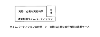
- time partitioning in order to ensure that the execution of a task is completed within the period of the time partition, the time of the time partition is changed from the worst case of the actually required execution time. There are also things like taking a lot. That is, the time partition time is set with a margin more than the execution time when the task execution time becomes the longest.
- the present invention has been made on the basis of the above-described knowledge, and in time partitioning, a safety control device and a safety that can execute a task at a constant period while guaranteeing independence of safety-related systems.
- An object is to provide a control method.
- the safety control device includes a processor, a safety-related task for executing processing related to ensuring functional safety of a control target, and other non-safety related processing for executing processing related to control of the control target.
- a system program that controls assignment of execution time of the processor to a task; and a storage unit that stores end information indicating the end of processing in the task, the processor executing the system program,
- the safety-related time partition in which the execution time is assigned to the safety-related task when the safety-related task is in an executable state, and the non-safety-related task when the non-safety-related task is in an executable state.
- Scheduling non-safety related time partitions that are assigned execution time Scheduling the task according to scheduling information indicating that a period of at least one of the safety-related time partition and the non-safety-related time partition starts at a constant period, and the processor
- the processor By executing the task in the time partition of the period, when the process in the task is completed, the end information indicating the end of the process in the task is stored in the storage unit, and the execution time for the task is released.
- the processor can execute the task in the fixed-period time partition. Even if the task is in an executable state, the allocation of the execution time to the task is suppressed, and the processor executes the system program so that the time partition period of the fixed period ends. By the time when the period in the next period of the time partition starts, the end information stored in the storage unit is deleted.
- the safety control method according to the second aspect of the present invention is a safety control method in which an execution time of a processor is allocated to a safety-related task when the safety-related task that executes a process related to ensuring functional safety of a control target is in an executable state.
- Scheduling contents of the related time partition and the non-safety related time partition to which the execution time is assigned to the non-safety related task when the non-safety related task that executes the process related to the control of the control target is in an executable state Scheduling the task according to scheduling information indicating that a period of at least one time partition of the safety-related time partition and the non-safety-related time partition starts at a constant cycle, and A step of assigning the execution time to a task in the time partition of the fixed period, and when the execution of the process in the task to which the execution time is assigned is finished, the storage unit stores end information indicating the end of the process in the task And storing the end information in the storage unit when scheduling the task in the time partition having the fixed period and releasing the execution time for the task and making the task executable.
- Embodiment 1 of invention It is a block diagram which shows the structural example of the safety control apparatus concerning Embodiment 1 of invention. It is a figure for demonstrating the concept of the time partitioning in Embodiment 1 of invention. It is a conceptual diagram for demonstrating the concept of the resource partitioning in Embodiment 1 of invention. It is a figure which shows the relationship between the partition scheduler and task started by the execution environment provided by OS shown in FIG. It is a figure which shows the specific example of a scheduling pattern. It is a figure which shows the specific example of a scheduling pattern. It is a flowchart which shows the specific example of the process sequence of a partition scheduler. It is a flowchart which shows the specific example of the reset process procedure of a microcontroller.
- the safety control device 1 is mounted on a service robot, a transportation device, or the like, and executes safety control for ensuring functional safety.
- the safety control device 1 is configured to execute a safety-related application and a non-safety-related application on the same computer system.
- FIG. 1 is a block diagram illustrating a configuration example of the safety control device 1 according to the present embodiment.
- the processor 10 obtains a program (instruction stream), decodes an instruction, and performs arithmetic processing according to the instruction decoding result.
- the safety control device 1 may have a multiprocessor configuration having a plurality of processors 10.
- the processor 10 may be a multi-core processor.
- the processor 10 provides a multiprogramming environment by executing an operating system (OS) 100 as a system program.
- OS operating system
- a multi-programming environment is an environment in which multiple programs are executed in parallel by periodically switching and executing multiple programs, or by switching the programs to be executed in response to the occurrence of a certain event. means.
- Multiprogramming is sometimes called multiprocess, multithread, multitask, etc.
- a process, a thread, and a task mean a program unit that is executed in parallel in a multiprogramming environment.
- the multi-programming environment included in the processor 10 of the present embodiment may be a multi-process environment or a multi-thread environment.
- the execution memory 11 is a memory used for program execution by the processor 10.
- the execution memory 11 stores programs (such as the OS 100 and applications 101 to 103) loaded from the nonvolatile memory 13, input / output data of the processor 10, and the like.
- the processor 10 may directly execute these programs from the nonvolatile memory 13 without loading the programs from the nonvolatile memory 13 to the execution memory 11.
- the execution memory 11 may be a random accessible volatile memory such as SRAM (Static Random Access Memory) or DRAM (Dynamic Random Access Memory).
- SRAM Static Random Access Memory
- DRAM Dynamic Random Access Memory
- the execution memory 11 in FIG. 1 represents a logical unit. That is, the execution memory 11 may be, for example, a combination of a plurality of SRAM devices, a combination of a plurality of DRAM devices, or a combination of an SRAM device and a DRAM device.
- the I / O port 12 is used for data transmission / reception with an external device.
- the external device is a visual sensor that can measure an obstacle around the service robot, an actuator that operates the service robot, or the like.
- the non-volatile memory 13 is a memory device capable of stably maintaining the stored contents as compared with the execution memory 11 without receiving power supply.
- the nonvolatile memory 13 is a ROM (Read Only Memory), a flash memory, a hard disk drive or an optical disk drive, or a combination thereof.
- the nonvolatile memory 13 stores the OS 100 and the applications 101 to 103.
- at least a part of the nonvolatile memory 13 may be configured to be removable from the safety control device 1.
- the memory storing the applications 101 to 103 may be removable.
- at least a part of the nonvolatile memory 13 may be disposed outside the safety control device 1.
- the OS 100 is executed by the processor 10 to use task resources including task scheduling, interrupt management, time management, resource management using hardware resources such as the processor 10, the execution memory 11, and the nonvolatile memory 13. Provides inter-task synchronization and inter-task communication mechanism.
- the OS 100 has a function of protecting hardware resources temporally and spatially.
- the hardware resources include the processor 10, the execution memory 11, and the I / O port 12.
- temporal protection is performed by partitioning a temporal resource called the execution time of the processor 10. Specifically, temporal protection is performed by partitioning the execution time of the processor 10 and assigning a task (process or thread) to each partition (referred to as a time partition).
- the scheduling function (partition scheduler 21) of the OS 100 guarantees the use of resources including the execution time of the processor 10 for tasks assigned to each time partition (hereinafter sometimes referred to as TP).
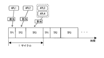
- FIG. 2 is a conceptual diagram related to time partitioning.
- a predetermined cycle time is divided into three TP1, TP2, and TP3 is shown.
- the first 20 Tick is defined as TP1
- the middle 30 Tick is defined as TP2
- the second 50 Tick is defined as TP3.
- the first application (APL1) to the fourth application (APL4) are assigned to any one of TP1 to TP3.
- the scheduling function (partition scheduler 21) of the OS 100 selects and determines which of TP1 to TP3 is activated as time elapses. Then, the application assigned to the active TP is executed by the processor 10.
- partitioning fixed resources including the execution memory 11 and the I / O port 12 and assigning tasks to each partition referred to as a resource partition.
- the scheduling function (partition scheduler 21) of the OS 100 prohibits a task from accessing other resources beyond a pre-assigned resource partition (hereinafter sometimes referred to as RP).
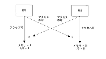
- FIG. 3 is a conceptual diagram related to resource partitioning.
- two RPs RP1 and RP2 are shown.
- a part of the execution memory 11 and the nonvolatile memory 13 (A area) and a part of the I / O port 12 (port A) are allocated to RP1.
- another part (B area) of the execution memory 11 and the nonvolatile memory 13 and another part (port B) of the I / O port 12 are allocated to RP2.
- Access from RP1 to the resource assigned to RP2 is prohibited, and access from RP2 to the resource assigned to RP1 is prohibited.
- the actuator needs to be accessible from both the normal control application 102 and the safety control application 103. Therefore, the I / O port for controlling the actuator may be shared by the RP to which the normal control application 101 belongs and the RP to which the safety control application 102 belongs.
- the applications 101 to 103 are executed in a multiprogramming environment provided by the OS 100 and the processor 10.
- the safety monitoring application 101 executes the processor 10 to monitor the execution status of the normal control application 102, monitor the execution status of the safety control application 103, and monitor input / output data to the I / O port 12.
- Instruction code to make it Further, the safety monitoring application 101 includes an instruction code for causing the processor 10 to execute a result notification to the partition scheduler 21. That is, the safety monitoring application 101 is a safety related application.
- the normal control application 102 includes an instruction code for causing the processor 10 to execute a control procedure for causing a control target such as a service robot to perform a normal function / operation. Further, the normal control application 102 includes an instruction code for causing the processor 10 to execute a result notification to the partition scheduler 21. That is, the normal control application 102 is a non-safety related application.
- the safety control application 103 includes an instruction code for causing the processor 10 to execute a control procedure determined to ensure functional safety in response to a case where some abnormality is detected. Further, the safety control application 103 includes an instruction code for causing the processor 10 to execute a result notification to the partition scheduler 21. That is, the safety control application 103 is a safety-related application.
- the reset circuit 14 resets the microcontroller 15 based on a signal from the OS 100. A reset mechanism of the microcontroller 15 using the reset circuit 14 will be described later.
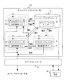
- FIG. 4 is a diagram showing the relationship between the partition scheduler 21 and the tasks 24, 26, and 28 that are activated in the multiprogramming environment provided by the OS 100.
- the microcontroller 15 includes a processor 10, an execution memory 11, an I / O port 12, a non-volatile memory 13, and the like. 4 illustrates a configuration in which the reset circuit 14 is provided outside the microcontroller 15, but a configuration in which the reset circuit 14 is included in the microcontroller 15 may be employed.
- the clock signal from an external clock source is supplied to the microcontroller 15, and the processor 10 and the like operate at a predetermined timer cycle based on this clock signal.
- the predetermined timer cycle is described as 1 Tick.
- the partition scheduler 21 operates every 1 Tick, and at each TP, the task schedulers 23, 25, 27 and tasks (safety monitoring task 24, normal control task 26, safety The control task 28) operates every 1 Tick.
- the partition scheduler 21 operates every 1 tick and performs TP switching (partition scheduling).
- the partition scheduler 21 selects and determines which of TP1 to TP3 is activated during the next 1 Tick. Furthermore, the partition scheduler 21 starts the operation of the task scheduler related to the selected TP.
- the partition scheduler 21 refers to the scheduling table 22 and performs partition scheduling in accordance with a scheduling pattern that defines TP settings.
- the scheduling table 22 holds a scheduling pattern that defines the TP switching order and timing.
- the scheduling table 22 holds at least two different scheduling patterns. One is a scheduling pattern that is applied when abnormality detection by the safety monitoring task 24 is not performed (that is, during normal time). The other is a scheduling pattern applied when an abnormality is detected by the safety monitoring task 24.
- normal control scheduling pattern A scheduling pattern applied at the time of detecting an abnormality is called a “safe control scheduling pattern”.
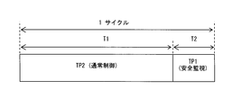
- FIG. 5A shows a specific example of the normal control scheduling pattern.
- TP2 to which the normal control task 26 belongs is assigned to the first half (T1) of one cycle time.
- TP1 to which the safety monitoring task 24 belongs is assigned to the second half (T2) of one cycle time.
- T1 to which the safety monitoring task 24 belongs is assigned to the second half (T2) of one cycle time.
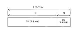
- FIG. 5B shows a specific example of the safety control scheduling pattern.
- TP3 to which the safety control task 28 belongs is assigned to the first half (T3) of one cycle time.
- TP1 to which the safety monitoring task 24 belongs is assigned to the second half (T4) of one cycle time.
- T3 first half
- T4 second half
- the safety control task 28 and the safety monitoring task 24 are repeatedly scheduled.
- each TP is illustrated as including only one task, but actually includes one or more tasks.
- the normal control task A and the normal control task B may be included in the normal control TP2.
- the safety monitoring task 24 is a task generated when the safety monitoring application 101 is activated. In the example of FIG. 4, the safety monitoring task 24 is assigned to TP1 and RP1. The safety monitoring task 24 monitors the execution status of the normal control task 26 that is a non-safety related application, monitors the safety control task 28 that is a safety related application, and monitors input / output data of the I / O port 12. Furthermore, the safety monitoring task 24 notifies the partition scheduler 21 of the task execution status.
- the normal control task 26 is a task generated when the normal control application 102 is activated. In the example of FIG. 4, the normal control task 26 is assigned to TP2 and RP2. The normal control task 26 performs control for causing a control target such as a service robot to perform a normal function / operation. Further, the normal control task 26 notifies the partition scheduler 21 of the task execution status.
- the safety control task 28 is a task generated when the safety control application 103 is activated.
- the safety control task 28 is assigned to TP3 and RP3.
- the safety control task 28 performs control determined to ensure functional safety in response to any abnormality being detected. Further, the safety control task 28 notifies the partition scheduler 21 of the task execution status.
- a task can call a system call (service call) of the OS 100 and notify the partition scheduler 21 of the result via the OS 100.
- the task sets a flag value according to the execution status, and the partition scheduler 21 executes the task according to the flag set value. The situation can also be judged.
- the partition scheduler 21 operates every 1 tick, and selects and determines which of TP1 to TP3 is activated. Further, the partition scheduler 21 starts the operation of the task scheduler related to the selected TP. Then, task scheduling is performed by the task schedulers 23, 25, and 27 starting operations, and the processor 10 executes the tasks in the TP according to the order scheduled by the task schedulers 23, 25, and 27. Go. As a result, the application assigned to the active TP is executed by the processor 10.
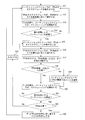
- FIG. 6 is a flowchart showing a specific example of the processing procedure of the partition scheduler 21.
- the partition scheduler 21 that operates every 1 tick operates the task scheduler of TPX (S11).
- the variable X indicates the number of TP, and X is a value other than 1. That is, in S11, either TP2 or TP3 except for TP1 for safety monitoring is operated.
- FIG. 6 a case where scheduling is executed according to a normal control scheduling pattern (for example, FIG. 5A) or a safety control scheduling pattern (for example, FIG. 5B) will be described as an example. That is, when the next TP following TP2 or TP3 is TP1, and when an abnormality in TP2 is detected in TP1, the next TP selected and determined based on the result from TP1 is TP3 Will be described as an example.
- the task scheduler of TPX that started the operation in S11 executes the task in TPX according to the priority (S12).
- the partition scheduler 21 starts TP scheduling (S13). That is, the partition scheduler 21 selects and determines which TP is to be activated during the next 1 Tick according to the scheduling pattern.
- the partition scheduler 21 If the partition scheduler 21 does not change the TP to be activated next (No in S14), the partition scheduler 21 returns to S11 and continues the operation for the same TPX. Therefore, the processing from S11 to S14 is repeated until the TPX switching timing comes.
- the partition scheduler 21 When changing the TP to be activated next (Yes in S14), the partition scheduler 21 operates the task scheduler of the time partition to be changed (S15). Here, the task scheduler of TP1 is operated. Then, the task scheduler 23 of TP1 executes the tasks in TP1 according to the priority (S16).
- the safety monitoring task 24 executed by TP1 monitors the execution status of the normal control task 26 and the input / output data of the I / O port 12, and determines whether these are normal (S17). As a result of the determination, if it is determined that there is an abnormality (No in S18), the safety monitoring task 24 notifies the partition scheduler 21 of the result (S19).
- the partition scheduler 21 starts scheduling again (S20).
- the partition scheduler 21 selects and determines which TP to activate during the next 1 Tick according to the scheduling pattern, and if the TP to be activated next is not changed (No in S21), returns to S15. , The operation for TP1 is continued.
- the partition scheduler 21 changes the TP to be activated next (Yes in S21), the partition scheduler 21 further determines whether or not TPX is normal according to the notification result from TP1 in S19 (S22). . If the result of the determination is abnormal (No in S22), the partition scheduler 21 selects and determines TP3 as the TP to be activated during the next 1 Tick (S23).
- the partition scheduler 21 selects and determines a TPX other than TP1 and TP3 as a TP to be activated during the next 1 Tick (S24).
- S15 TP2 is changed to TP1, and remains TP1 from S15 to S21.
- TPX TP3 is satisfied in S23 (that is, the safety control scheduling pattern starting from TP3 is switched).
- TP3 safety monitoring
- TP1 normal control
- TP3 safety control
- TP5 safety control partitions
- the partition scheduler 21 determines the type of abnormal state of the execution status (data input / output) related to TPX, and selects either TP3 or TP5 for safety control according to the abnormal type. Good.
- either TP2 or TP4 for normal control may be selected.
- the OS 100 includes the partition scheduler 21 that selects and determines the partition to be activated next in response to a notification from the TP1 for safety monitoring or a notification from each TP. ing.
- the partition scheduler 21 operates at a predetermined timer period independently of the tasks executed in each TP. Since the partition scheduler 21 that operates independently at a predetermined timer cycle has a partition scheduling function, the following effects can be obtained.
- the safety monitoring task 24 selects and determines a scheduling pattern in addition to monitoring the execution status of the normal control task 26 and monitoring input / output data of the I / O port 12. Therefore, it is necessary to allocate the execution time required for the selection / determination for TP2 to which the safety monitoring task 24 belongs.
- the safety monitoring task 24 and the normal control task 26 need to be executed alternately. For this reason, in the conventional technology, the scheduling pattern selection / determination by the safety monitoring task 24 is executed every time as the normal control task 26 is executed. This is necessary for the selection and determination of the scheduling pattern by the safety monitoring task 24.
- the safety monitoring task 24 itself does not need to execute the selection / determination of the scheduling pattern.
- the execution time required for the partition scheduler 21 to select and determine the scheduling pattern is short. Therefore, compared with the prior art, the safety monitoring TP1 can be assigned in a shorter time, and the normal control TP2 can be assigned for a longer time.
- the partition scheduler 21 selects and determines TP3 for safety control in response to a result notification from TP1 (S23) or selects and determines TP2 for normal control.
- S23 result notification from TP1
- TP2 selects and determines TP2 for normal control.
- S24 the present invention is not limited to this.
- the configuration is such that the execution status is notified to the partition scheduler 21 from each of TP1 to TP3.
- the TP3 for safety control may be selected and determined according to the result notification from the TP.
- the partition scheduler 21 Since the partition scheduler 21 that operates independently receives the result notifications from all TPs, the partition scheduler 21 can grasp the situation regarding all TPs in an integrated manner. Therefore, for example, when the partition scheduler 21 decides and selects the next partition in response to the result notification from the safety monitoring TP1, the partition scheduler 21 considers the situation of each TP. The next partition can be determined and selected only from the TP in the normal state. Therefore, compared to the prior art, there is an effect that more accurate partition scheduling can be realized.
- FIGS. 7 and 8 are flowcharts showing a specific example of the reset processing procedure of the microcontroller 15 using the reset circuit 14.
- the partition scheduler 21 that operates every 1 tick has a reset function of the microcontroller 15.
- the partition scheduler 21 detects an abnormality in the OS 100, it performs an abnormality treatment in conjunction with the reset circuit 14.
- the reset circuit 14 resets the microcontroller 15 based on a signal from the partition scheduler 21.
- TPX is a TP other than TP1 and TP3.
- the safety monitoring task 24 belonging to TP1 determines whether the abnormality in TPX is an abnormality that can be handled by the safety control task 28 belonging to TP3 (S36). . If it is not an abnormality that can be dealt with by TP3 (No in S36), the safety monitoring task 24 belonging to TP1 notifies the partition scheduler 21 that the abnormality has an emergency stop (S37). The partition scheduler 21 that has received the notification from the safety monitoring task 24 belonging to TP1 outputs a reset instruction signal to the reset circuit 14, and the reset circuit 14 that has received the reset instruction signal resets the microcontroller 15 (S38).
- the safety monitoring task 24 belonging to TP1 notifies the partition scheduler 21 that TPX is abnormal (S39). Receiving the notification from TP1, the partition scheduler 21 switches from TPX to TP3 (S40).
- TPX is a TP other than TP1 and TP3.
- the partition scheduler 21 stops the transmission signal to the reset circuit 14, and in S63, the partition scheduler 21 sends a signal to the reset circuit 14. Is different in sending. Further, the difference in S61 of FIG. 8 is that the reset circuit 14 resets the microcontroller 15 in response to the transmission signal from the partition scheduler 21 being interrupted.
- the other processing from S58 to S64 shown in FIG. 8 is basically the same as the processing from S36 to S40 shown in FIG.
- the partition scheduler 21 in addition to the case where the partition scheduler 21 intentionally instructs the reset circuit 14 to reset, the partition scheduler 21 itself does not operate normally for some reason, or the partition scheduler 21 Even when a failure occurs in the signal line that transmits the transmission signal to the reset circuit 14, the microcontroller 15 can be reliably reset. At the same time, it can be assured that TP switching is normally executed every 1 tick.
- the partition scheduler 21 outputs the reset instruction signal to the reset circuit 14 or stops the transmission signal to the reset circuit 14 in response to the result notification from the TP1.
- the reset instruction signal may be output to the reset circuit 14 or the transmission signal to the reset circuit 14 may be stopped in response to the result notification from any of TP1 to TP3.
- the configuration of the safety control device 1 according to the second embodiment is the same as the configuration of the safety control device 1 according to the first embodiment. Further, the relationship between the partition scheduler 21 and the tasks 24, 26, and 28 is the same as the configuration of the safety control device 1 according to the first embodiment. Hereinafter, description of the same contents as those of the safety control device 1 according to the first embodiment will be omitted.
- the partition scheduler 21 when a task that executes a process that needs to be executed at a constant cycle ends, the partition scheduler 21 is notified that the process has ended.
- a task for executing a process that needs to be executed at a constant cycle is the safety control task 28.
- the safety control task 28 stores information indicating the end of the process at TP3 in the execution memory 11 when the process ends. Specifically, the execution memory 11 stores a TP process end flag indicating whether or not the process at TP3 has ended.
- the safety control task 28 sets a TP process end flag when the process ends. That is, when the TP process end flag is set, the TP process end flag indicates that the execution of the safety control task 28 has ended and the process in the safety control task 28 has ended. When the TP process end flag is off, the TP process end flag indicates that the execution of the safety control task 28 has not ended and the process in the safety control task 28 has not ended.
- the safety control task 28 operates the task scheduler 27 after setting the TP process end flag. That is, after setting the TP process end flag, the safety control task 28 releases the execution time of the processor 10 and transitions to an executable state. The task status such as the executable status will be described later.
- the task scheduler 27 schedules tasks belonging to TP3. If the TP process end flag is set, the task scheduler 27 sets the execution time of the processor 10 relative to the safety control task 28 even if the safety control task 28 is executable. Suppresses assignment.
- the partition scheduler 21 clears the TP processing end flag when switching the TP.
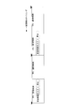
- the scheduling table 22 holds the scheduling pattern illustrated in FIG.
- the TP switching order and timing are defined such that the period in which TP3 is active is a constant period.
- FIG. 10 is a task state transition diagram.
- the tasks 24, 26, and 28 take one of an execution state, an executable state, a wait state, a double wait state, a forced wait state, and a dormant state.
- the execution state is a state in which the execution time of the processor 10 is assigned to the task by the task schedulers 23, 25, 27, and 29.
- a task is in an execution state, the task is being executed by the processor 10.
- the task in the execution state transitions to an executable state when, for example, the execution time of the processor 10 allocated by the task schedulers 23, 25, 27, and 29 is used up.
- the task in the execution state transitions to a waiting state when sleeping, for example.
- the executable state is a state in which the execution time of the processor 10 can be assigned to the task, but the execution time of the processor 10 is not assigned to the task.
- the executable state is, for example, a state where a task is awakened.
- the task in the executable state transitions to the execution state when the execution time of the processor 10 is assigned by the task scheduler 23, 25, 27, 29, for example.
- the waiting state is a state in which the execution time of the processor 10 cannot be assigned to the task and the execution time of the processor 10 is not assigned.
- the waiting state is, for example, a state where the task is sleeping.
- a task in a waiting state transitions to an executable state when it wakes up from a sleeping state, for example, due to expiration of a sleep time or reception of inter-task communication from another task.
- the forced waiting state is a state where the execution time of the processor 10 cannot be assigned to the task and the execution time of the processor 10 is not assigned.
- the forced waiting state is a state in which execution of a task in an executable state is temporarily prohibited by, for example, the partition scheduler 21, the task scheduler 23, 25, 27, or another task.
- the task in the forced waiting state transitions to an executable state when the forced waiting state is canceled by the partition scheduler 21, the task scheduler 23, 25, 27, or another task.
- the double waiting state is a state in which the execution time of the processor 10 cannot be assigned to the task and the execution time of the processor 10 is not assigned.
- the double waiting state is a state in which the waiting task is temporarily prohibited from being executed by, for example, the partition scheduler 21, the task scheduler 23, 25, 27, or another task.
- the task in the forced waiting state transitions to the waiting state when the forced waiting state is canceled by the partition scheduler 21, the task scheduler 23, 25, 27, or another task.
- a task in a forced waiting state transitions to a forced waiting state when it wakes up.
- the hibernation state is a state in which the execution time of the processor 10 cannot be assigned to the task and the execution time of the processor 10 is not assigned.
- the dormant state is, for example, a state where the task has not been activated or a state where the task has ended.
- FIG. 11 is a flowchart showing a specific example of the end processing procedure of the safety control task 28 according to the second embodiment.
- the task scheduler 27 assigns the execution time of the processor 10 to the safety control task 28.
- the safety control task 28 to which the execution time of the processor 10 is assigned executes the process defined for ensuring functional safety as described above.
- the safety control task 28 sets a TP process end flag stored in the execution memory 11 (S81).
- the safety control task 28 releases the execution time of the processor 10 and transitions to an executable state.
- the safety control task 28 transitions to an executable state, for example, by executing a system call that releases the execution time of the processor 10.
- the execution time of the processor 10 is assigned to the task scheduler 27, and the task scheduler 27 is executed (S82).
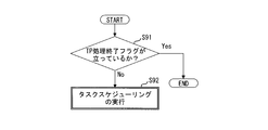
- FIG. 12 is a flowchart illustrating a specific example of a processing procedure of the task scheduler 27 according to the second embodiment.
- the task scheduler 27 determines whether or not the TP process end flag is set (S91). When the TP process end flag is set (Yes in S91), the task scheduler 27 does not execute task scheduling. Thus, for example, after the process in the safety control task 28 is executed in TP3, the process is not executed again in the same TP3 period even if the safety control task 28 is in an executable state. Can do. When the TP process end flag is not set (No in S91), the task scheduler 27 executes scheduling of tasks belonging to TP3 (S92). As a result, the execution time of the processor 10 is assigned to the safety control task 28.
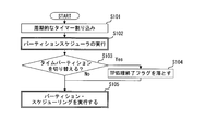
- FIG. 13 is a flowchart of a specific example of the processing procedure of the partition scheduler 21 according to the second embodiment.
- the processor 10 executes the partition scheduler 21 (S102). As described above, by executing the partition scheduler 21 from a timer (not shown) included in the microcontroller 15 every time there is a periodic timer interruption, the partition scheduler 21 operates in a predetermined timer cycle. When executed, the partition scheduler 21 determines whether to switch the TP according to the scheduling pattern (S103). For example, referring to the scheduling pattern, it is determined by confirming whether or not the timing executed this time is the TP switching timing.
- the partition scheduler 21 clears the TP processing end flag (S104).
- the TP processing end flag is cleared. Therefore, the safety control task 28 is executed by the task scheduler 27 next time TP3 becomes active.
- TP3 becomes active at a constant period. Therefore, the safety control task 28 is executed at a constant cycle.
- the TP processing end flag may be cleared not when the TP is switched but before TP3 becomes active next time. This is because the safety control task 28 is executed after a certain period if the TP processing end flag is dropped before TP3 becomes active.
- Step S104 the partition scheduler 21 performs partition scheduling (S105).
- the safety control task 28 when the process ends, stores information indicating the end of the process in the execution memory 11 and releases the execution time of the processor 10. And transition to the executable state. Then, in the task scheduling, when the information indicating the end of the process is stored in the execution memory 11 in the task scheduling, even if the safety control task 28 is in an executable state, the processor 10 for the safety control task 28 The execution time allocation is suppressed.
- TP3 is set to have a constant cycle. Further, the partition scheduler 21 deletes information indicating the end of the process from the end of the period of TP3 to the start of the period in the next cycle of TP3. According to this, while preventing the safety control task 28 from being executed again within the same period of TP3, the safety control task 28 is started when the period of TP3 after the next fixed period is started. An executable state can be maintained. In addition, it is not necessary to wake up the safety control task 28 from another task. Therefore, according to the second embodiment, it is possible to execute a task at a constant cycle while ensuring the independence of safety-related systems.
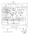
- FIG. 14 is a diagram showing the relationship between the partition scheduler 21 and tasks 24, 26, 28 A, 28 B, and 28 C that are activated in the multiprogramming environment provided by the OS 100.
- description of the same contents as those of the second embodiment of the present invention will be omitted.
- a plurality of safety control tasks 28A, 28B, and 28C are activated.
- the safety control task 28A is a task that executes a process that needs to be executed at a constant cycle.
- the safety control tasks 28B and 28C do not need to be periodically executed, but are tasks that are desired to be executed only once in TP3.
- the priority of the task is set in advance so that the safety control task 28A is the highest, the safety control task 28B is the next highest, and the safety control task 28C is the lowest. That is, the safety control task 28A that needs to be executed at a constant cycle is set with the highest priority.
- Each of the safety control tasks 28A, 28B, and 28C stores information indicating the end of the processing in the task in the execution memory 11 when the processing in the task ends.
- the execution memory 11 stores a plurality of task process end flags indicating whether or not the process in the task has ended, corresponding to each of the safety control tasks 28A, 28B, and 28C.
- Each of the safety control tasks 28A, 28B, and 28C sets a task process end flag when the process ends. That is, when the task process end flag is set, the task process end flag indicates that the process in the safety control task is ended. When the task process end flag is off, the task process end flag indicates that the process in the safety control task has not ended.
- Each of the safety control tasks 28A, 28B, and 28C operates the task scheduler 27 after setting the task processing end flag. That is, each of the safety control tasks 28A, 28B, and 28C sets the TP process end flag, releases the execution time of the processor 10, and transitions to an executable state.
- the task scheduler 27 performs the scheduling of tasks belonging to TP3 in order from the task with the highest priority. If the task processing end flag is set, the task scheduler 27 sets the safety control task from the execution time allocation target of the processor 10 even if the safety control task corresponding to the task processing end flag is in an executable state. exclude.
- the partition scheduler 21 clears the task process end flag when switching the TP.
- Embodiment 3 a case will be described in which the partition scheduler 21 performs partition scheduling according to the scheduling pattern illustrated in FIG. That is, in the third embodiment, the scheduling table 22 holds the scheduling pattern illustrated in FIG.
- the TP switching order and timing are defined so that the period in which TP3 is active is a constant period.
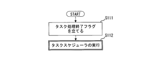
- FIG. 16 is a flowchart illustrating a specific example of the end processing procedure of the safety control tasks 28A, 28B, and 28C according to the third embodiment.
- the task scheduler 27 assigns the execution time of the processor 10 to any one of the safety control tasks 28A, 28B, and 28C.
- the safety control task to which the execution time of the processor 10 is assigned executes a process defined for ensuring functional safety as described above.
- the safety control task sets a task process end flag stored in the execution memory 11 (S111).
- the safety control task 28 sets the task processing end flag, releases the execution time of the processor 10, and transitions to an executable state. As a result, the execution time of the processor 10 is allocated to the task scheduler 27, and the task scheduler 27 is executed (S112).
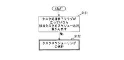
- FIG. 17 is a flowchart illustrating a specific example of a processing procedure of the task scheduler 27 according to the third embodiment.
- the task scheduler 27 determines whether or not a task processing end flag is set (S121).
- the task scheduler 27 excludes the safety control task corresponding to the task processing end flag from the schedule target.
- the safety control task 28A is executed in TP3
- the safety control task 28A is executed in an executable state, it can be prevented from being executed again within the same TP3 period.
- the task scheduler 27 performs scheduling of tasks belonging to TP3 (S122).
- the tasks are executed in the order of the safety control task 28A, the safety control task 28B, and the safety control task 28C according to the priority of the task.
- the processing shown in FIGS. 16 and 17 is executed, and the safety control tasks 28A, 28B, and 28C are executed as shown in FIG.
- the safety control task 28A having the highest priority is executed by the task scheduler 27.
- the safety control task 28A sets a task process end flag when the process is completed (S111).
- the safety control task 28B sets a task process end flag when the process is finished (S111).
- the safety control task 28C sets a task process end flag when the process is finished (S111).
- FIG. 18 is a flowchart of a specific example of the processing procedure of the partition scheduler 21 according to the third embodiment.
- the processor 10 executes the partition scheduler 21 (S132).
- the partition scheduler 21 determines whether or not the TP is switched according to the scheduling pattern (S133).
- the partition scheduler 21 clears the task processing end flag corresponding to the task belonging to TP3 (S134). Thereby, for example, when switching from TP3 to the next TP2, the task processing end flag is cleared. Therefore, the safety control tasks 28A, 28B, and 28C are executed by the task scheduler 27 next time TP3 becomes active.
- the partition scheduler 21 performs partition scheduling (S135). Note that, as described above, the TP processing end flag may be set not when the TP is switched but before TP3 becomes active next time.
- the execution time of the processor 10 is assigned to the safety control tasks 28B and 28C having a lower priority than the safety control task 28A in TP3. Is assigned. Therefore, after the execution of the safety control task 28A, the time during which the processor 10 is not performing any processing can be eliminated, and the utilization efficiency of the processor 10 can be improved.
- the safety control task 28A since the priority of the safety control task 28A that needs to be executed at a constant cycle is the highest, the safety control task 28A is executed when the period of TP3 of the constant cycle is started. Executed. Therefore, also in the third embodiment, the safety control task 28A can be executed at a constant cycle.
- the configuration of the safety control device 1 according to the fourth embodiment is the same as the configuration of the safety control device 1 according to the first embodiment. Further, the relationship between the partition scheduler 21 and the tasks 24, 26, and 28 is the same as the configuration of the safety control device 1 according to the first embodiment. Hereinafter, description of the same contents as those of the safety control device 1 according to the first embodiment will be omitted.
- the partition scheduler 21 when a task that executes a process that needs to be executed at a constant cycle ends, the partition scheduler 21 is notified that the process has ended.
- a task for executing a process that needs to be executed at a constant cycle is the safety control task 28.
- the partition scheduler 21 performs partition scheduling according to the scheduling pattern illustrated in FIG. That is, in the fourth embodiment, the scheduling table 22 holds the scheduling pattern illustrated in FIG.
- the TP switching order and timing are defined so that the period in which TP3 becomes active is a constant period.
- the TP switching timing is also referred to as “TP boundary”.
- the TP boundary at which the cycle ends is registered for the safety control task 28.
- the TP boundary at which the cycle ends is the switching timing of the TP at which processing in the safety control task 28 that needs to be executed at a constant cycle should be completed at that time.
- the TP boundary where the cycle ends is held at the switching timing from TP3 to which the safety control task 28 that needs to be executed at a constant cycle belongs to the next TP2.
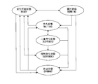
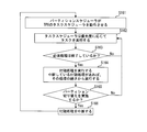
- FIG. 20 is a flowchart showing a specific example of the processing procedure of the partition scheduler 21 according to the fourth embodiment.
- the processor 10 executes the partition scheduler 21 (S142).
- the partition 21 executes the following processing when executed at the TP boundary.
- the partition scheduler 21 determines whether there is a task that registers a TP boundary whose cycle ends at the current TP boundary (S143). In the fourth embodiment, since the TP boundary at which the cycle ends is registered for the safety control task 28, it is determined that there is a task that registers the TP boundary at which the cycle ends at the TP boundary from TP3 to TP2.
- the partition scheduler 21 determines whether or not there is a process end notification from the task (S144). In the fourth embodiment, it is determined whether or not there is a notification from the safety control task 28.
- the end of the process may be notified to the partition scheduler 21 by a flag indicating the end of the process, as in the second or third embodiment, and from the task to the partition scheduler 21 by inter-task communication. You may make it notify.
- the partition scheduler 21 determines that there is an abnormality (S145). In that case, the partition scheduler 21 executes processing according to the abnormality (S146).
- the partition scheduler 21 switches from TP3 to another TP. Further, when the abnormality is an abnormality that requires an emergency stop because the process of the safety control task 28 is not completed at a constant cycle, the partition scheduler 21 resets the microcontroller 15.
- the partition scheduler 21 When there is no task that registers the TP boundary at which the cycle ends (No in S143), or when the end of processing from the safety control task 28 is notified (Yes in S144), the partition scheduler 21 performs partition scheduling. Execute (S147). At this time, when the safety control task 28 belonging to TP3 is in a waiting state, the partition scheduler 21 makes the safety control task 28 executable. For example, the partition scheduler 21 wakes up the safety control task 28 and makes it executable by inter-task communication with the safety control task 28. As a result, the safety control task 28 is executed at a constant cycle.
- the safety control task 28 remains in an executable state, and the safety control task 28 is not executed within the same TP3 period by a flag indicating the end of processing.
- the safety control task 28 may be executed at a constant cycle.
- the partition scheduler 21 executes a task scheduler belonging to TP next to TP3 (S148).
- the partition scheduler 21 when the period of the time partition in which the safety control task 28 is executed at a constant cycle ends, the partition scheduler 21 notifies the safety control task 28 of the end of the process. It is determined whether or not. According to this, it is not necessary to create a monitoring mechanism for individual applications such as the safety control application 103 that generates the safety control task 28, and thus the software configuration can be simplified.
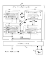
- FIG. 21 is a diagram illustrating the relationship between the partition scheduler 21 and tasks 24, 26 A, 26 B, 28, and 30 that are activated in the multiprogramming environment provided by the OS 100.
- description of the same contents as those of the first embodiment of the present invention will be omitted.
- the OS 200 according to the fifth embodiment has a plurality of safety control partitions TP3 and TP4.
- a plurality of normal control tasks 26A and 26B are activated.
- each of the safety monitoring task 24, the normal control tasks 26A and 26B, and the safety control task 30 is a task that executes a process that needs to be executed at a constant cycle.
- the partition scheduler 21 performs partition scheduling according to the scheduling pattern illustrated in FIG. That is, in the fifth embodiment, the scheduling table 22 holds the scheduling pattern illustrated in FIG.
- a TP boundary for starting a task and a TP boundary for ending a task are held as illustrated in FIG.
- a TP boundary at which a task is started is a timing at which execution of the task is started.
- the TP boundary at which a task ends is the timing at which the task should have been completed by then.
- TP1, TP3, and TP4 are the same.
- the length of each period of TP2 is the same. Therefore, in FIG. 22, a TP boundary for starting a task is defined at a timing at which each of the tasks 24, 26A, 26B, and 30 is executed at a constant period. Further, in FIG. 22, a TP boundary for ending a task is defined at a timing at which each of the tasks 24, 26A, 26B, and 28 should finish executing the task within a certain period.
- the task scheduler 29 schedules the safety control task 30 belonging to TP4 in the same manner as the task schedulers 23, 25, and 27.
- the partition scheduler 21 When switching the TP, the partition scheduler 21 starts the execution of the task if the TP boundary for starting the task is set at the TP boundary at the switching timing of the scheduling pattern. In addition, when the TP is switched, the partition scheduler 21 determines whether or not the execution of the task has ended if a TP boundary for ending the task is set at the TP boundary at the switching timing of the scheduling pattern.
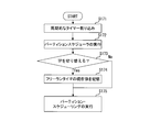
- FIG. 23 is a flowchart of a specific example of the processing procedure of the partition scheduler 21 according to the third embodiment.
- the processor 10 executes the partition scheduler 21 (S152).
- the partition 21 determines whether or not the current timing is a TP boundary (S153). That is, it is determined whether or not TP switching occurs.
- the partition scheduler 21 determines whether or not the execution of the task in which the TP boundary for ending the task is set at the TP boundary has been completed (S154). ). Whether or not the execution of the task has ended may be determined by the partition scheduler 21 based on a flag indicating the end of the process, as in the second or third embodiment. The determination may be made based on whether the partition scheduler 21 is notified of the end of the process.
- the partition scheduler 21 determines that it is abnormal (S155). In that case, the partition scheduler 21 executes processing according to the abnormality (S156). If the abnormality caused by the task execution not completing at a certain period is an abnormality that can be dealt with by switching to another TP and executing the task belonging to that TP, the partition scheduler 21 Switch from to another TP. Further, when the abnormality is an abnormality that requires an emergency stop because the execution of the task does not end at a constant cycle, the partition scheduler 21 resets the microcontroller 15.
- the partition scheduler 21 sets a TP boundary for starting the task at the TP boundary. If there is a task that is present, the task is put into an execution state (S157). The partition scheduler 21 executes partition scheduling (S158). Then, the partition scheduler 21 executes the task scheduler belonging to the switching destination TP by partition scheduling (S159). The executed task scheduler starts execution of the task that the partition scheduler 21 enters the execution state.
- the start timing for starting execution of a task is set for the TP boundary at a fixed cycle timing.
- an end determination timing for determining the end of task execution is set at the same fixed cycle timing.
- the partition scheduler 21 starts the task execution at the TP boundary where the start timing is set, and determines whether the task execution is completed at the TP boundary where the end determination timing is set. According to this, it is not necessary to create a monitoring mechanism for each application that executes each of the tasks 24, 26A, 26B, and 30, so that the software configuration can be simplified.
- FIG. 24 is a block diagram illustrating a configuration example of the safety control device 2 according to the sixth embodiment.
- description of the same contents as those of the safety control device 1 according to the first embodiment will be omitted.
- the nonvolatile memory 13 stores a RAM (Random Access Memory) check application 104.
- the RAM check application 104 includes an instruction code for causing the RAM check process to be executed.
- the RAM check process is a process in which the RAM check application 104 checks whether or not the execution memory 11 is normal by reading / writing data from / to the execution memory 11.
- the RAM check application 104 may include an instruction code for causing the processor 10 to execute a result notification to the partition scheduler 21.
- FIG. 25 is a diagram showing the relationship between the partition scheduler 21 and tasks 24, 26, 28, and 31 that are activated in the multiprogramming environment provided by the OS 100.
- description of the same contents as those of the safety control device 1 according to the first embodiment will be omitted.
- the RAM check task 31 is a task generated when the RAM check application 104 is activated.
- the RAM check task 31 performs processing for checking whether or not the execution memory 11 is normal.
- the essential process is a process executed by the normal control task 26 and the accompanying process is a process executed by the RAM check task 31 will be described.
- the priority of the normal control task 26 that executes essential processing is set higher than that of the RAM check task 31 that executes incidental processing.
- the normal control task 26 that executes the essential process has more time than the execution time when the execution time of the normal control task 26 becomes the longest.
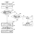
- FIG. 27 is a flowchart of a specific example of the scheduling process procedure according to the sixth embodiment.
- the partition scheduler 21 When switching TP to TPX, the partition scheduler 21 operates the task scheduler of TPX (S161). Here, a case where TPX is TP2 and the task scheduler 25 is executed will be described.
- the task scheduler 25 executes the task according to the priority of the task (S162). Here, the normal control task 26 having a higher priority is executed first.
- the task scheduler 25 continues the execution of the normal control task 26 that executes the essential process until the essential process ends (No in S163, S162).
- the task scheduler 25 executes the RAM check task 31 that executes the accompanying process (S164). Note that if the process in the RAM check task 31 is interrupted within the period of the previous TP2, the process is continuously executed. Until the TP switching timing comes, the execution of the RAM check task 31 by the task scheduler 25 is continued (No in S165, Yes in S162, S163, S164).
- the partition scheduler 21 When it is time to switch TP (Yes in S165), the partition scheduler 21 performs TP switching. As a result, the execution of the RAM check task 31 belonging to TP2 before switching is interrupted if the execution has not ended. That is, the accompanying process by the RAM check task 31 is interrupted (S166).
- the execution time of the processor 10 is further increased to the RAM check task 31 having a lower priority than the normal control task 26 in TP2. Is assigned. Therefore, after the execution of the safety control task 28A, the time during which the processor 10 is not executing any processing can be eliminated, and the execution time of the processor 10 can be used effectively.
- FIG. 28 is a flowchart of a specific example of the processing procedure of the partition scheduler 21 according to the seventh embodiment.
- the processor 10 executes the partition scheduler 21 (S172).
- the partition scheduler 21 determines whether or not TP switching occurs based on the scheduling pattern (S173).
- the partition scheduler 21 stores the current value indicated by the free-run timer in the execution memory 11. As a result, the time at the start of the TP is stored in the execution memory 11.
- a free-run timer (not shown) is provided in the processor 10.
- partition scheduler 21 executes partition scheduling (S175).
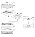
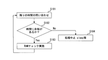
- FIG. 29 and 30 are flowcharts showing a specific example of the processing procedure of the RAM check task 31 according to the seventh embodiment.
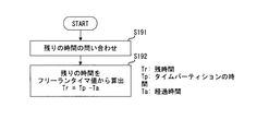
- the RAM check task 31 performs an inquiry process for the remaining time when performing a RAM check (S181). In the inquiry processing for the remaining time, the RAM check task 31 determines whether or not there is room for executing the RAM check in the remaining time of TP2 (S182).
- the execution memory 11 subject to the RAM check is a memory in which exclusive control is performed for access to the execution memory 11. That is, a RAM check (S183), which will be described later, locks access to the execution memory 11 from another task for a certain period of time, checks a certain range of the execution memory 11, and then performs unlocking. Therefore, if switching to another TP occurs during execution of the RAM check, the RAM check task 31 remains locked. That is, tasks belonging to other TPs cannot access the execution memory 11. For this reason, in the seventh embodiment, the RAM check (S183) is performed when there is enough room to execute the RAM check.
- the RAM check task 31 calculates the remaining time from the free-run timer value in the inquiry about the remaining time (S191). Specifically, the RAM check task 31 subtracts the free-run timer value at the start of TP2 stored in the execution memory 11 by the partition scheduler 21 from the current value of the free-run timer, so that TP2 becomes active. The elapsed time Ta from is calculated. The RAM check task 31 calculates the remaining time of TP2 by subtracting the elapsed time Ta from the time of TP2. For example, information indicating the time of TP2 is stored in the execution memory 11 in advance. Then, the RAM check task 31 calculates the remaining time of TP2 by referring to the information.
- the RAM check task 31 interrupts the process (S184). At this time, the RAM check task 31 releases the execution time of the processor 10 by sleeping, for example.
- the RAM check task 31 performs a RAM check (S183).
- the RAM check process is performed when the remaining period of TP2 is less than the period required for the RAM check process.
- the processing of the task 31 is interrupted and the execution time of the processor 10 is released. According to this, it is possible to prevent a series of processes that are not desired to be divided, such as the RAM check process, from being divided by switching of the TP.
- the RAM check process is executed when the remaining period of TP2 is equal to or longer than the period required for the RAM check process. According to this, since it is ensured that switching from TP2 to another TP does not occur until the RAM check process is completed, exclusive control is not required in the RAM check process.
- Embodiments 1 to 7 may be implemented in combination.
- the case where the OS has TP1 to TP4 is illustrated, but the type and number of TPs are not limited to this.
- the scheduling pattern is not limited to that exemplified in the present embodiment.
- the types and number of tasks belonging to the TP are not limited to those exemplified in the present embodiment.
- Safety control device 10 Processor 11
- Execution memory 12 I / O port 13
- Reset circuit 15 Microcontroller 21 Partition scheduler 22 Scheduling tables 23, 25, 27, 29 Task scheduler 24
- Safety control task 31 RAM check task 100
- Operating system 101 Safety monitoring application 102 Normal control application 103
- Safety control application 104 RAM check application
Landscapes
- Engineering & Computer Science (AREA)
- Physics & Mathematics (AREA)
- General Physics & Mathematics (AREA)
- Robotics (AREA)
- Mechanical Engineering (AREA)
- Software Systems (AREA)
- Theoretical Computer Science (AREA)
- Automation & Control Theory (AREA)
- General Engineering & Computer Science (AREA)
- Safety Devices In Control Systems (AREA)
- Programmable Controllers (AREA)
- Debugging And Monitoring (AREA)
Abstract
Description
本実施の形態にかかる安全制御装置1は、サービスロボットや運輸機器等に搭載されて機能安全確保のための安全制御を実行する。安全制御装置1は、安全関連アプリケーションと非安全関連アプリケーションを同一のコンピュータシステムで実行するよう構成される。図1は、本実施の形態にかかる安全制御装置1の構成例を示すブロック図である。
まず、図5Aに例示した通常制御スケジューリングパターンに従って、S11においてスケジューリングを開始した場合を説明する。この場合、S11ではTPX=TP2として開始し、S12~S14にかけてもTPX=TP2のままである。そして、S15でTP2からTP1へと変更され、S15~S21にかけてTP1のままである。S18でTP2に関する実行状況(データ入出力)が正常であると判定されていた場合には、S24では、TPX=TP2となる(つまり、TP2から開始する通常制御スケジューリングパターンが継続される。)。一方で、S18でTP2に関する実行状況(データ入出力)が異常であると判定されていた場合には、S23で、TPX=TP3となる(つまり、TP3から開始する安全制御スケジューリングパターンに切り替わる。)。
続いて、本実施の形態2にかかる安全制御装置1について説明する。なお、本実施の形態2にかかる安全制御装置1の構成は、本実施の形態1にかかる安全制御装置1の構成と同様である。また、パーティションスケジューラ21とタスク24、26、28との関係についても、本実施の形態1にかかる安全制御装置1の構成と同様である。以下、実施の形態1にかかる安全制御装置1と同様の内容については説明を省略する。
続いて、本実施の形態3にかかる安全制御装置1について説明する。なお、本実施の形態3にかかる安全制御装置1の構成は、本実施の形態2にかかる安全制御装置1の構成と同様であるため、説明を省略する。
続いて、本実施の形態4にかかる安全制御装置1について説明する。なお、本実施の形態4にかかる安全制御装置1の構成は、本実施の形態1にかかる安全制御装置1の構成と同様である。また、パーティションスケジューラ21とタスク24、26、28との関係についても、本実施の形態1にかかる安全制御装置1の構成と同様である。以下、実施の形態1にかかる安全制御装置1と同様の内容については説明を省略する。
続いて、本実施の形態5にかかる安全制御装置1について説明する。なお、本実施の形態5にかかる安全制御装置1の構成は、本実施の形態1にかかる安全制御装置1の構成と同様であるため、説明を省略する。
続いて、図24を参照して、本実施の形態6にかかる安全制御装置2について説明する。図24は、本実施の形態6のかかる安全制御装置2の構成例を示すブロック図である。以下、実施の形態1にかかる安全制御装置1と同様の内容については説明を省略する。
続いて、本実施の形態7にかかる安全制御装置2について説明する。なお、本実施の形態7にかかる安全制御装置1の構成は、本実施の形態6にかかる安全制御装置1の構成と同様であるため、説明を省略する。また、パーティションスケジューラ21とタスク24、26、28、31との関係についても、本実施の形態6にかかる安全制御装置2の構成と同様であるため、説明を省略する。
10 プロセッサ
11 実行用メモリ
12 I/Oポート
13 不揮発性メモリ
14 リセット回路
15 マイクロコントローラ
21 パーティションスケジューラ
22 スケジューリングテーブル
23、25、27、29 タスクスケジューラ
24 安全監視タスク
26、26A、26B 通常制御タスク
28、28A、28B、28C、30 安全制御タスク
31 RAMチェックタスク
100 オペレーティングシステム
101 安全監視アプリケーション
102 通常制御アプリケーション
103 安全制御アプリケーション
104 RAMチェックアプリケーション
Claims (7)
- プロセッサと、
制御対象の機能安全の確保に関する処理を実行する安全関連タスク、及び、その他の前記制御対象の制御に関する処理を実行する非安全関連タスクに対する前記プロセッサの実行時間の割り当てを制御するシステムプログラムと、
前記タスクにおける処理の終了を示す終了情報が格納される記憶部と、
を備え、
前記プロセッサは、前記システムプログラムを実行することによって、前記安全関連タスクが実行可能状態である場合に当該安全関連タスクに前記実行時間が割り当てられる安全関連タイムパーティション、及び、前記非安全関連タスクが実行可能状態である場合に当該非安全関連タスクに前記実行時間が割り当てられる非安全関連タイムパーティションのスケジューリング内容を、当該安全関連タイムパーティション及び当該非安全関連タイムパーティションの少なくとも1つタイムパーティションの期間が一定周期で開始されるように示すスケジューリング情報に従って、前記タスクをスケジューリングし、
前記プロセッサは、前記一定周期のタイムパーティションにおけるタスクを実行することによって、当該タスクにおける処理が終了したときに、当該タスクにおける処理の終了を示す終了情報を前記記憶部に格納して、当該タスクに対する前記実行時間を解放して当該タスクを実行可能状態とし、
前記プロセッサは、前記スケジューリングにおいて、前記記憶部に前記終了情報が格納されている場合、前記一定周期のタイムパーティションにおいて、当該一定周期のタイムパーティションにおけるタスクが実行可能状態であっても、当該タスクに対する前記実行時間の割り当てを抑止し、
前記プロセッサは、前記システムプログラムを実行することによって、前記一定周期のタイムパーティションの期間が終了するときから、当該タイムパーティションの次の周期における期間が開始されるときまでに、前記記憶部に格納された終了情報を削除する
安全制御装置。 - 前記一定周期のタイムパーティションは、さらに、前記安全関連タスク及び前記非安全関連タスクよりも優先度が低く、任意の処理を実行する少なくとも1つの任意処理タスクに前記実行時間が割り当てられ、
前記プロセッサは、前記任意処理タスクを実行することによって、当該任意処理タスクにおける処理が終了したときに、当該任意処理タスクにおける処理の終了を示す終了情報を前記記憶部に格納して、当該任意処理タスクに対する前記実行時間を解放して当該任意処理タスクを実行可能状態とし、
前記プロセッサは、前記スケジューリングにおいて、より優先度の高いタスクに優先的に前記実行時間を割り当てるとともに、前記一定周期のタイムパーティションにおけるタスクが実行可能状態であっても、当該タスクにおける処理の終了を示す終了情報が前記記憶部に格納されている場合、当該タスクに対する前記実行時間の割り当てを抑止する
請求項1に記載の安全制御装置。 - 前記プロセッサは、前記スケジューリングにおいて、前記一定周期のタイムパーティションの期間が終了したときに、当該タイムパーティションにおけるタスクの処理の終了を示す終了情報が前記記憶部に格納されていない場合、異常と判定して当該異常に応じた処理を実行する
請求項1又は2に記載の安全制御装置。 - 前記一定周期のタイムパーティションにおけるタスクは、当該一定周期のタイムパーティションに対して、当該タスクを実行開始する開始タイミング、及び、当該タスクの実行終了を判定する終了判定タイミングが予め定められており、
前記プロセッサは、前記スケジューリングにおいて、前記開始タイミングが定められたタイムパーティションの期間が開始されるときに、当該タイムパーティションにおけるタスクの実行を開始するとともに、前記終了判定タイミングが定められたタイムパーティションの期間が終了したときに、前記記憶部に前記終了情報が格納されていない場合、異常と判定して当該異常に応じた処理を実行する
請求項1に記載の安全制御装置。 - 前記安全関連タイムパーティション又は前記非安全関連タイムパーティションは、さらに、当該安全関連タイムパーティション又は当該非安全関連タイムパーティションにおける安全関連タスク又は非安全関連タスクよりも優先度が低く、任意の処理を実行する少なくとも1つの任意処理タスクに前記実行時間が割り当てられ、
前記プロセッサは、前記スケジューリングにおいて、より優先度の高いタスクに優先的に前記実行時間を割り当てる
請求項1に記載の制御装置。 - 前記プロセッサは、前記任意処理タスクを実行することによって、前記任意処理タスクに前記実行時間が割り当てられる安全関連タイムパーティション又は非安全関連タイムパーティションが終了するまでの期間が、当該任意処理タスクが実行する処理に必要な期間に満たない場合、当該任意処理タスクに対する前記実行時間を解放する
請求項5に記載の安全制御装置。 - 制御対象の機能安全の確保に関する処理を実行する安全関連タスクが実行可能状態である場合に当該安全関連タスクにプロセッサの実行時間が割り当てられる安全関連タイムパーティション、及び、その他の前記制御対象の制御に関する処理を実行する非安全関連タスクが実行可能状態である場合に当該非安全関連タスクに前記実行時間が割り当てられる非安全関連タイムパーティションのスケジューリング内容を、当該安全関連タイムパーティション及び当該非安全関連タイムパーティションの少なくとも1つタイムパーティションの期間が一定周期で開始されるように示すスケジューリング情報に従って、前記タスクをスケジューリングして、当該一定周期のタイムパーティションにおいて、当該一定周期のタイムパーティションにおけるタスクに前記実行時間を割り当てるステップと、
前記実行時間が割り当てられたタスクにおける処理の実行が終了したときに、当該タスクにおける処理の終了を示す終了情報を前記記憶部に格納して、当該タスクに対する前記実行時間を解放して当該タスクを実行可能状態とするステップと、
当該一定周期のタイムパーティションにおいてタスクをスケジューリングするときに、前記記憶部に前記終了情報が格納されている場合、当該一定周期のタイムパーティションにおけるタスクが実行可能状態であっても、当該タスクに対する前記実行時間の割り当てを抑止するステップと、
当該一定周期のタイムパーティションの期間が終了するときから、当該タイムパーティションの次の周期における期間が開始されるときまでに、前記記憶部に格納された終了情報を削除するステップと、
を備えた安全制御方法。
Priority Applications (5)
| Application Number | Priority Date | Filing Date | Title |
|---|---|---|---|
| US13/259,519 US8706265B2 (en) | 2011-01-31 | 2011-01-31 | Safety controller and safety control method |
| JP2011532432A JP5136695B2 (ja) | 2011-01-31 | 2011-01-31 | 安全制御装置および安全制御方法 |
| CN201180038086.1A CN103080858B (zh) | 2011-01-31 | 2011-01-31 | 安全控制装置及安全控制方法 |
| PCT/JP2011/000526 WO2012104898A1 (ja) | 2011-01-31 | 2011-01-31 | 安全制御装置および安全制御方法 |
| EP11822791.7A EP2672341B1 (en) | 2011-01-31 | 2011-01-31 | Safety control device and safety control method |
Applications Claiming Priority (1)
| Application Number | Priority Date | Filing Date | Title |
|---|---|---|---|
| PCT/JP2011/000526 WO2012104898A1 (ja) | 2011-01-31 | 2011-01-31 | 安全制御装置および安全制御方法 |
Publications (1)
| Publication Number | Publication Date |
|---|---|
| WO2012104898A1 true WO2012104898A1 (ja) | 2012-08-09 |
Family
ID=46602153
Family Applications (1)
| Application Number | Title | Priority Date | Filing Date |
|---|---|---|---|
| PCT/JP2011/000526 WO2012104898A1 (ja) | 2011-01-31 | 2011-01-31 | 安全制御装置および安全制御方法 |
Country Status (5)
| Country | Link |
|---|---|
| US (1) | US8706265B2 (ja) |
| EP (1) | EP2672341B1 (ja) |
| JP (1) | JP5136695B2 (ja) |
| CN (1) | CN103080858B (ja) |
| WO (1) | WO2012104898A1 (ja) |
Cited By (4)
| Publication number | Priority date | Publication date | Assignee | Title |
|---|---|---|---|---|
| CN103095707A (zh) * | 2013-01-17 | 2013-05-08 | 苏州亿倍信息技术有限公司 | 一种终端安全的信息处理方法及系统 |
| WO2014110947A1 (zh) * | 2013-01-17 | 2014-07-24 | 苏州亿倍信息技术有限公司 | 一种终端安全的处理方法及系统 |
| WO2015025597A1 (ja) * | 2013-08-22 | 2015-02-26 | 日立オートモティブシステムズ株式会社 | 車両制御装置 |
| CN109684070A (zh) * | 2018-08-29 | 2019-04-26 | 西安电子科技大学 | 一种云计算并行操作中的调度方法 |
Families Citing this family (15)
| Publication number | Priority date | Publication date | Assignee | Title |
|---|---|---|---|---|
| WO2012104899A1 (ja) * | 2011-01-31 | 2012-08-09 | トヨタ自動車株式会社 | 安全制御装置および安全制御方法 |
| EP2672342B1 (en) * | 2011-01-31 | 2017-03-01 | Toyota Jidosha Kabushiki Kaisha | Safety control device and safety control method |
| JP2014211689A (ja) * | 2013-04-17 | 2014-11-13 | トヨタ自動車株式会社 | 安全制御装置および安全制御方法 |
| JP6626240B2 (ja) * | 2014-03-13 | 2019-12-25 | オムロン株式会社 | コントローラ |
| US9830211B2 (en) | 2014-05-11 | 2017-11-28 | Safetty Systems Ltd | Framework as well as method for developing time-triggered computer systems with multiple system modes |
| GB2526082B (en) * | 2014-05-11 | 2016-03-30 | Safetty Systems Ltd | A monitoring unit as well as method for predicting abnormal operation of time-triggered computer systems |
| GB2526083B (en) * | 2014-05-11 | 2016-03-30 | Safetty Systems Ltd | A framework as well as method for developing time-triggered computer systems with multiple system modes |
| CN108430897B (zh) * | 2015-11-30 | 2020-11-03 | 哈贝尔公司 | 用于数据通信总线上的通道带宽的同步脉冲控制的系统、装置和方法 |
| US11099525B2 (en) | 2016-12-08 | 2021-08-24 | National Instruments Corporation | Control of safety input/output by non-safety system during safe times |
| CN107363835B (zh) * | 2017-08-06 | 2019-11-08 | 北京镁伽机器人科技有限公司 | 运动控制部件的配置方法、装置、介质和机器人系统 |
| JP7003217B2 (ja) * | 2018-03-05 | 2022-01-20 | 三菱電機株式会社 | エレベーター安全制御装置 |
| JP6927089B2 (ja) | 2018-03-05 | 2021-08-25 | オムロン株式会社 | 制御装置、システムプログラム、制御方法 |
| JP7025966B2 (ja) | 2018-03-20 | 2022-02-25 | 日立Astemo株式会社 | 車両制御装置 |
| JP7003952B2 (ja) * | 2019-03-14 | 2022-01-21 | オムロン株式会社 | 制御システム、サポート装置およびサポート装置用のプログラム |
| CN110434855B (zh) * | 2019-08-20 | 2021-03-30 | 广东博智林机器人有限公司 | 机器人施工的方法、装置和工控机 |
Citations (4)
| Publication number | Priority date | Publication date | Assignee | Title |
|---|---|---|---|---|
| JPH07295840A (ja) * | 1994-04-28 | 1995-11-10 | Nec Ic Microcomput Syst Ltd | マルチプログラミングにおける事象管理方式 |
| JP2006338426A (ja) * | 2005-06-03 | 2006-12-14 | Hitachi Ltd | 計算機システム |
| JP2009251663A (ja) * | 2008-04-01 | 2009-10-29 | Denso Corp | タスク制御方法及びマルチタスクシステム |
| JP2010271759A (ja) | 2009-05-19 | 2010-12-02 | Toyota Motor Corp | 安全制御装置および安全制御方法 |
Family Cites Families (13)
| Publication number | Priority date | Publication date | Assignee | Title |
|---|---|---|---|---|
| US4318173A (en) * | 1980-02-05 | 1982-03-02 | The Bendix Corporation | Scheduler for a multiple computer system |
| US5636124A (en) * | 1995-03-08 | 1997-06-03 | Allen-Bradley Company, Inc. | Multitasking industrial controller |
| JP2000207228A (ja) * | 1999-01-18 | 2000-07-28 | Star Micronics Co Ltd | モ―タ制御装置 |
| US7302685B2 (en) * | 2000-06-02 | 2007-11-27 | Honeywell International Inc. | Methods and apparatus for sharing slack in a time-partitioned system |
| JP2002086379A (ja) | 2000-09-13 | 2002-03-26 | Toshiba Corp | ロボット、ロボットの制御方法およびロボットを動作するプログラムを記憶したコンピュータ読み取り可能な記憶媒体 |
| DE102004054571B4 (de) * | 2004-11-11 | 2007-01-25 | Sysgo Ag | Verfahren zur Verteilung von Rechenzeit in einem Rechnersystem |
| US7613595B2 (en) * | 2005-03-01 | 2009-11-03 | The Math Works, Inc. | Execution and real-time implementation of a temporary overrun scheduler |
| WO2008023427A1 (fr) * | 2006-08-24 | 2008-02-28 | Netcleus Systems Corporation | Dispositif de traitement de tâche |
| JP2008191823A (ja) | 2007-02-02 | 2008-08-21 | Omron Corp | 安全管理方法、安全管理システムおよび安全制御機器 |
| US7870299B1 (en) * | 2008-02-06 | 2011-01-11 | Westinghouse Electric Co Llc | Advanced logic system |
| DE102008060011A1 (de) * | 2008-11-25 | 2010-05-27 | Pilz Gmbh & Co. Kg | Sicherheitssteuerung und Verfahren zum Steuern einer automatisierten Anlage |
| US9678483B2 (en) * | 2011-01-26 | 2017-06-13 | Honeywell International Inc. | Programmable controller with both safety and application functions |
| CN103026309B (zh) * | 2011-01-31 | 2015-04-29 | 丰田自动车株式会社 | 安全控制装置以及安全控制方法 |
-
2011
- 2011-01-31 US US13/259,519 patent/US8706265B2/en active Active
- 2011-01-31 EP EP11822791.7A patent/EP2672341B1/en not_active Not-in-force
- 2011-01-31 CN CN201180038086.1A patent/CN103080858B/zh not_active Expired - Fee Related
- 2011-01-31 WO PCT/JP2011/000526 patent/WO2012104898A1/ja active Application Filing
- 2011-01-31 JP JP2011532432A patent/JP5136695B2/ja active Active
Patent Citations (4)
| Publication number | Priority date | Publication date | Assignee | Title |
|---|---|---|---|---|
| JPH07295840A (ja) * | 1994-04-28 | 1995-11-10 | Nec Ic Microcomput Syst Ltd | マルチプログラミングにおける事象管理方式 |
| JP2006338426A (ja) * | 2005-06-03 | 2006-12-14 | Hitachi Ltd | 計算機システム |
| JP2009251663A (ja) * | 2008-04-01 | 2009-10-29 | Denso Corp | タスク制御方法及びマルチタスクシステム |
| JP2010271759A (ja) | 2009-05-19 | 2010-12-02 | Toyota Motor Corp | 安全制御装置および安全制御方法 |
Non-Patent Citations (1)
| Title |
|---|
| See also references of EP2672341A4 * |
Cited By (7)
| Publication number | Priority date | Publication date | Assignee | Title |
|---|---|---|---|---|
| CN103095707A (zh) * | 2013-01-17 | 2013-05-08 | 苏州亿倍信息技术有限公司 | 一种终端安全的信息处理方法及系统 |
| WO2014110947A1 (zh) * | 2013-01-17 | 2014-07-24 | 苏州亿倍信息技术有限公司 | 一种终端安全的处理方法及系统 |
| CN103095707B (zh) * | 2013-01-17 | 2015-09-09 | 苏州亿倍信息技术有限公司 | 一种终端安全的信息处理方法及系统 |
| WO2015025597A1 (ja) * | 2013-08-22 | 2015-02-26 | 日立オートモティブシステムズ株式会社 | 車両制御装置 |
| JP2015039983A (ja) * | 2013-08-22 | 2015-03-02 | 日立オートモティブシステムズ株式会社 | 車両制御装置 |
| CN105636832A (zh) * | 2013-08-22 | 2016-06-01 | 日立汽车系统株式会社 | 车辆控制装置 |
| CN109684070A (zh) * | 2018-08-29 | 2019-04-26 | 西安电子科技大学 | 一种云计算并行操作中的调度方法 |
Also Published As
| Publication number | Publication date |
|---|---|
| JPWO2012104898A1 (ja) | 2014-07-03 |
| EP2672341B1 (en) | 2015-09-09 |
| EP2672341A1 (en) | 2013-12-11 |
| JP5136695B2 (ja) | 2013-02-06 |
| CN103080858A (zh) | 2013-05-01 |
| US8706265B2 (en) | 2014-04-22 |
| US20120029659A1 (en) | 2012-02-02 |
| EP2672341A4 (en) | 2014-08-06 |
| CN103080858B (zh) | 2014-07-16 |
Similar Documents
| Publication | Publication Date | Title |
|---|---|---|
| JP5136695B2 (ja) | 安全制御装置および安全制御方法 | |
| JP5136693B2 (ja) | 安全制御装置および安全制御方法 | |
| JP5267737B2 (ja) | 安全制御装置および安全制御方法 | |
| JP5321686B2 (ja) | 安全制御装置および安全制御方法 | |
| JP5446447B2 (ja) | 安全制御装置および安全制御方法 | |
| JP5240402B2 (ja) | 安全制御装置および安全制御方法 | |
| JP5621857B2 (ja) | 安全制御装置および安全制御方法 | |
| JP5834935B2 (ja) | 安全制御装置及び安全制御方法 | |
| JP5906584B2 (ja) | 制御装置及び制御方法 | |
| JP5633501B2 (ja) | 制御装置および制御方法 | |
| JP5853716B2 (ja) | 情報処理装置およびタスク制御方法 | |
| JP5699910B2 (ja) | 制御装置および制御方法 | |
| JP2015212969A (ja) | 情報処理装置およびdmaコントローラの動作確認方法 |
Legal Events
| Date | Code | Title | Description |
|---|---|---|---|
| WWE | Wipo information: entry into national phase |
Ref document number: 201180038086.1 Country of ref document: CN |
|
| WWE | Wipo information: entry into national phase |
Ref document number: 2011532432 Country of ref document: JP |
|
| WWE | Wipo information: entry into national phase |
Ref document number: 13259519 Country of ref document: US |
|
| WWE | Wipo information: entry into national phase |
Ref document number: 2011822791 Country of ref document: EP |
|
| 121 | Ep: the epo has been informed by wipo that ep was designated in this application |
Ref document number: 11822791 Country of ref document: EP Kind code of ref document: A1 |
|
| NENP | Non-entry into the national phase |
Ref country code: DE |