WO2012102169A1 - Heating sleeve exchange method and heating sleeve exchange tool for vertical injection molding machine - Google Patents
Heating sleeve exchange method and heating sleeve exchange tool for vertical injection molding machine Download PDFInfo
- Publication number
- WO2012102169A1 WO2012102169A1 PCT/JP2012/051094 JP2012051094W WO2012102169A1 WO 2012102169 A1 WO2012102169 A1 WO 2012102169A1 JP 2012051094 W JP2012051094 W JP 2012051094W WO 2012102169 A1 WO2012102169 A1 WO 2012102169A1
- Authority
- WO
- WIPO (PCT)
- Prior art keywords
- heating cylinder
- plate
- heating
- injection molding
- molding machine
- Prior art date
Links
Images


Classifications
-
- B—PERFORMING OPERATIONS; TRANSPORTING
- B22—CASTING; POWDER METALLURGY
- B22D—CASTING OF METALS; CASTING OF OTHER SUBSTANCES BY THE SAME PROCESSES OR DEVICES
- B22D17/00—Pressure die casting or injection die casting, i.e. casting in which the metal is forced into a mould under high pressure
- B22D17/20—Accessories: Details
- B22D17/2015—Means for forcing the molten metal into the die
- B22D17/2023—Nozzles or shot sleeves
-
- B—PERFORMING OPERATIONS; TRANSPORTING
- B29—WORKING OF PLASTICS; WORKING OF SUBSTANCES IN A PLASTIC STATE IN GENERAL
- B29C—SHAPING OR JOINING OF PLASTICS; SHAPING OF MATERIAL IN A PLASTIC STATE, NOT OTHERWISE PROVIDED FOR; AFTER-TREATMENT OF THE SHAPED PRODUCTS, e.g. REPAIRING
- B29C45/00—Injection moulding, i.e. forcing the required volume of moulding material through a nozzle into a closed mould; Apparatus therefor
- B29C45/17—Component parts, details or accessories; Auxiliary operations
- B29C45/176—Exchanging the injection unit or parts thereof
-
- B—PERFORMING OPERATIONS; TRANSPORTING
- B29—WORKING OF PLASTICS; WORKING OF SUBSTANCES IN A PLASTIC STATE IN GENERAL
- B29C—SHAPING OR JOINING OF PLASTICS; SHAPING OF MATERIAL IN A PLASTIC STATE, NOT OTHERWISE PROVIDED FOR; AFTER-TREATMENT OF THE SHAPED PRODUCTS, e.g. REPAIRING
- B29C45/00—Injection moulding, i.e. forcing the required volume of moulding material through a nozzle into a closed mould; Apparatus therefor
- B29C45/17—Component parts, details or accessories; Auxiliary operations
- B29C45/72—Heating or cooling
- B29C45/74—Heating or cooling of the injection unit
Definitions
- the present invention relates to a heating cylinder replacement method and a heating cylinder replacement jig of a vertical injection molding machine, and more particularly to means for easily and safely attaching and detaching a heating cylinder to and from a heating cylinder holding plate provided in an injection unit.
- the vertical injection molding machine is attached in such a manner that the heating cylinder is suspended from the heating cylinder holding plate provided in the injection unit. Therefore, in order to remove the heating cylinder from the heating cylinder holding plate, the heating cylinder It is necessary to remove the bolt that fixes the heating cylinder to the heating cylinder holding plate while supporting and to remove the bolt, and to transfer the heating cylinder to a required working position or storage position.
- the heating cylinder since the heating cylinder is heavy, performing the bolt removing operation while supporting the heating tube with human power increases the physical burden on the operator and is severe to the operator.
- the heating cylinder may be dropped without being supported or may collide with other equipment, which is also a safety issue. Of course, the same problem occurs when the heating cylinder is attached to the heating cylinder holding plate.
- a holding device that moves up and down integrally with the screw driving device is detachably provided below a mounting plate that is a heating cylinder holding plate for mounting the screw driving device so as to be movable up and down.
- a technology has been proposed in which the plasticizing unit separated from the screw driving device is held by the holding device in a suspended state and slid to a position separated from the machine center position of the vertical injection molding machine (for example, a patent Reference 1).
- Patent Document 1 when the plasticizing unit is attached to or detached from the screw driving device, the plasticizing unit is held by the holding device and transferred to a predetermined position. There is no need to support it manually, and work can be done efficiently and safely.
- Patent Document 1 uses two L-shaped rails arranged opposite to each other as a holding device, and engages an engaging step formed on the plasticizing unit on the horizontal side of the rail. Therefore, it can be applied only to a specific plasticizing unit in which a predetermined engagement step portion is formed at a predetermined position, and cannot be universally applied to attachment / detachment of a plasticizing unit having no engagement step portion. There's a problem.
- the present invention has been made in view of the above-described points, and the object of the present invention is to be applied universally to existing vertical injection molding machines and to attach and detach the plasticizing unit even for non-experts.
- An object of the present invention is to provide a heating cylinder replacement method and a heating cylinder replacement jig capable of easily and efficiently performing work.
- the present invention relates to a heating cylinder replacement method, a die plate having an upper mold attached to the lower surface side, and a heating cylinder holding plate provided to be movable up and down with respect to the die plate. And a nozzle touch motor for moving the heating cylinder holding plate up and down, a heating cylinder whose upper end is detachably held on the heating cylinder holding plate, and a rotatable and vertically movable housing in the heating cylinder.
- a screw a metering electric servo motor that rotationally drives the screw, a linear motion plate that is vertically movable with respect to the die plate, and detachably holds an upper end of the screw, and the linear motion plate
- An injection electric servomotor that moves the screw up and down via a control device, a control device that controls driving of each motor, and a display device that can display a required display screen as appropriate.
- the control device causes the display device to drive the nozzle touch motor and to perform the heating cylinder replacement treatment for the die plate.
- the heating for the heating cylinder holding plate including a procedure for attaching and detaching a tool, a procedure for holding the heating cylinder to the heating cylinder replacement jig, and a procedure for transferring the heating cylinder held by the heating cylinder replacement jig
- the cylinder attachment / detachment procedure is displayed, and the operator performs the attachment / detachment operation of the heating cylinder with respect to the heating cylinder holding plate in accordance with the attachment / detachment operation procedure displayed on the display device.
- the heating cylinder attaching / detaching procedure with respect to the heating cylinder holding plate is displayed on the display device, and the worker performs the attaching / detaching operation of the heating cylinder according to the attaching / detaching procedure displayed on the display device, special knowledge and skill are obtained. Even an operator who does not have the need to replace the heating cylinder can perform the replacement operation of the heating cylinder at any time and smoothly. Further, in this case, when the heating tube attaching / detaching work procedure using the heating tube replacement jig is displayed on the display device, the operator performs the attaching / detaching operation of the heating tube using the required heating tube replacing jig. An operator can hold a heavy heating cylinder with a heating cylinder replacement jig and does not need to support this manually, so that the heating cylinder can be attached and detached easily and safely.
- the heating cylinder replacement jig is slidable on the slider body that is bolted to the upper surface of the die plate and the slider body. It has an attached slider plate and a cylindrical heating tube insertion holding portion fixed to the upper surface of the slider plate.
- the tip of the heating tube removed from the heating tube holding plate is moved by moving the heating tube insertion holding portion to just below the heating tube suspended from the heating tube holding plate. Can be inserted and held in the heating cylinder insertion holding section, and from that state, the heating cylinder is formed into a vertical injection molding by sliding the slider plate with the heating cylinder insertion holding section fixed to the slider body. It can be moved safely and easily to the side of the machine.
- the heating cylinder replacement jig of this configuration holds the heating cylinder by inserting the tip of the heating cylinder into the heating cylinder insertion holding section provided on the slider plate, so that the heating cylinder is specially processed. This is not necessary, and can be applied universally to replacement work of a heating cylinder having a general configuration.
- the heating cylinder replacement method for the vertical injection molding machine having the above-described configuration
- the heating cylinder is inserted and held by the side of the vertical injection molding machine.
- the slider plate is slid with respect to the slider body, and the heating cylinder held by the heating cylinder insertion holding part is placed below the heating cylinder holding plate.
- the heating cylinder When the heating cylinder is transferred to a predetermined position and the heating cylinder is removed from the heating cylinder holding plate, the tip of the heating cylinder removed from the heating cylinder holding plate is inserted into the heating cylinder insertion holding section, and then the slider plate Is slid with respect to the slider body, and the heating cylinder held by the heating cylinder insertion holding portion is transferred to a predetermined position on the side of the vertical injection molding machine.
- the heating cylinder can be transferred from one predetermined position to another predetermined position simply by sliding the slider plate with respect to the slider body, so that the heating cylinder can be easily replaced. be able to.
- the control device when the control device receives a drive command for the nozzle touch motor from an operator, the control device drives the nozzle touch motor. Controlling, raising or lowering the tip of the heating cylinder to an appropriate position that does not interfere with the heating cylinder replacement jig, and stopping at the appropriate position.
- the heating cylinder holding plate (heating cylinder) is first attached to the tip of the heating cylinder. Retract to a position where it does not interfere with the heating cylinder replacement jig, set the heating cylinder replacement jig on the die plate, and then hold the heating cylinder on the heating cylinder replacement jig (heating cylinder holding plate) Must be advanced to a predetermined position where the tip of the heating cylinder does not interfere with the heating cylinder replacement jig.
- the heating cylinder holding plate When the heating cylinder is attached to the heating cylinder holding plate, the heating cylinder holding plate is first retracted to a position where the end of the heating cylinder does not interfere with the heating cylinder holding plate, and the heating cylinder replacement jig (heating cylinder) is attached. After moving to just below the heating tube mounting part of the heating tube holding plate, the heating tube holding plate is moved to a predetermined position where the end of the heating tube does not interfere with the heating tube holding plate in order to bring the heating tube holding plate closer to the heating tube. Need to move forward.
- the heating cylinder holding plate (heating cylinder) is automatically moved to the appropriate position described above at each stage during the attaching / detaching operation, the operator visually observes the nozzle touch. Since there is no need to adjust the drive of the motor, the replacement operation of the heating cylinder can be performed easily and quickly.
- the present invention relates to a heating cylinder replacement jig, a slider body that is bolted to the upper surface of a die plate provided in a vertical injection molding machine, and is slidable on the slider body. And a cylindrical heating tube insertion holding portion fixed to the upper surface of the slider plate.
- the heating cylinder can be held and transferred by inserting the tip of the heating cylinder into the heating cylinder insertion holding section provided in the slider plate, so that the heating cylinder can be attached to and detached from the heating cylinder holding plate.
- it since it is not necessary to apply special processing to the heating cylinder, it can be applied universally to replacement work of a heating cylinder having a general configuration.
- the procedure for attaching / detaching the heating cylinder to / from the heating cylinder holding plate is displayed on the display device, and the operator performs the attaching / detaching operation of the heating cylinder according to the attachment / detachment procedure displayed on the display device. Even an operator having no knowledge or skill can replace the heating cylinder, and the replacement operation of the heating cylinder can be performed smoothly and at any time.
- the required heating tube replacement jig is used to attach and detach the heating cylinder, there is no need to manually support a heavy heating cylinder, reducing the burden on the operator, and making the heating cylinder easy to attach and detach. And can be safe.
- a heating cylinder replacement jig includes a slider main body bolted to the upper surface of a die plate provided in a vertical injection molding machine, a slider plate slidably provided on the slider main body, and the slider plate And a cylindrical heating tube insertion holding portion fixed to the upper surface of the heating tube, the heating tube can be held and transferred by inserting the leading end of the heating tube into the heating tube insertion holding portion.
- the attaching / detaching operation of the heating cylinder with respect to the plate can be facilitated, and since the heating cylinder need not be specially processed, the versatility of the jig can be enhanced.
- the upper surface of the die plate 2 in which the injection unit 1 configured in a vertical pattern is positioned at the top of the mold opening / closing unit configured in a vertical pattern. are attached via a hollow base bracket 3.
- An upper mold (not shown) is attached to the lower surface side of the die plate 2.
- the injection unit 1 is arranged opposite to each other, and the heating cylinder holding plate 4 and the linear motion plate 5 that move up and down with respect to the die plate 2 within a predetermined range, and the heating cylinder unit suspended from the heating cylinder holding plate 4 6, a nozzle touch ball screw mechanism 7 that moves up and down the heating cylinder unit 6 and an electric servo motor 8 for nozzle touch, and is housed in the heating cylinder unit 6 so as to be rotatable and movable up and down, and the base end portion is a direct acting plate 5, a screw 9 rotatably held by the motor 5, a metering electric servomotor 10 that rotationally drives the screw 9, an injection ball screw mechanism 11 that moves the linear motion plate 5 and the screw 9 forward and backward, and an electric servomotor for injection 12.
- the heating cylinder unit 6 includes a heating cylinder 6a, a nozzle 6b attached to the distal end portion thereof, and a hopper block 6c attached to the proximal end portion of the heating cylinder 6a.
- the nozzle 6b is opened on the die plate 2. Through the heating cylinder insertion hole 2a, it is pressed against a resin injection hole provided in an upper mold (not shown).
- the injection ball screw mechanism 11 includes a nut body 11a that is rotatably attached to the heating cylinder holding plate 4, and a screw shaft 11b that is screwed into the nut body 11a.
- the electric servo motor 8 is used as a nozzle touch motor, but a normal electric motor may be used instead. In the present specification, these may be collectively referred to as “nozzle touch motor”.
- the driving / stopping of the motors 8, 10, 12 provided in the injection unit 1 is controlled by a control device 21 provided in the vertical injection molding machine.
- a display device 22 is attached to the control device 21, and the setting conditions of the injection unit 1, the driving condition, the attaching / detaching procedure of the heating cylinder unit 6 with respect to the heating cylinder holding plate 4 and the like are displayed.
- a nut body 7a of a ball screw mechanism 7 for nozzle touch is rotatably held on the heating cylinder holding plate 4, and a screw shaft 7b of the ball screw mechanism 7 is screwed to the nut body 7a.
- Three ball screw mechanisms 7 are provided at an angular interval of 120 ° with the heating cylinder unit 6 as the center.
- the lower ends of the screw shafts 7b of the ball screw mechanisms 7 are fixed to the upper surface side of the base bracket 3, respectively.
- the upper end side of the screw shaft 7 b is fixed to the connection bracket 13.
- the screw shaft 7b of the ball screw mechanism 7 is formed so that the spiral groove for the ball screw mechanism and the linear groove for the ball spline mechanism cross, and the screw shaft 7b has the function of the screw shaft.
- Each screw shaft 7b is connected to a spline outer cylinder 14 fixed to the heating cylinder holding plate 4 and a spline outer cylinder 15 fixed to a linear motion plate 5 to be described later by ball spline coupling.
- the cylinder holding plate 4 and the linear motion plate 5 are movable in the axial direction of the screw shaft 7b and cannot be rotated.
- the rotation of the nozzle touch servomotor 8 is transmitted to a driven pulley 7c that rotates integrally with the nut body 7a of the ball screw mechanism 7, and the nut body 7a rotates, so that the heating cylinder holding plate 4 is integrated with the nut body 7a. Is driven down or up.
- the nozzle is reciprocated between a position where the nozzle abuts a resin injection hole of the upper mold (not shown) and a predetermined position where the nozzle does not interfere with a heating cylinder replacement jig described later.
- the linear motion plate 5 is equipped with a metering electric servo motor 10, and the rotation of the metering electric servo motor 10 is transmitted to a driven pulley 16 fixed to a rotating member that rotates integrally with the screw 9. Thereby, the screw 9 is rotationally driven.
- An electric servomotor 12 for injection is also attached to the linear motion plate 5, and the rotation of the electric servomotor 12 for injection is fixed to the heating cylinder holding plate 4 and the nut body 11 a. It is transmitted to the linear motion plate 5 through an injection ball screw mechanism 11 that is constituted by a screw shaft 11b that is screwed to the linear motion plate 11 and that is rotatably held by the linear motion plate 5. That is, the rotation of the injection electric servomotor 12 is transmitted to the driven pulley 17 that rotates integrally with the screw shaft 11b that constitutes the ball screw mechanism 11, and when the screw shaft 11b rotates, the heating cylinder holding plate 4 that is stopped at a predetermined position. The screw shaft 11b is linearly moved with respect to the nut body, whereby the linear motion plate 5 and the screw 9 are integrally driven downward or upward.
- the vertical injection molding machine including the injection unit 1 having such a configuration rotates the nozzle touch electric servomotor 8 in a predetermined direction during the molding operation to lower the heating cylinder holding plate 4.
- the nozzle provided at the tip is pressed against the resin injection hole of the upper mold, and this pressing state is maintained by the nozzle touch electric servomotor 8.
- the metering electric servo motor 10 is rotated in a predetermined direction to rotationally drive the screw 9 in a predetermined direction, and the resin material supplied to the proximal end side of the heating cylinder unit 6 is kneaded and plasticized.
- the screw 9 is fed to the distal end side of the screw 9 while being turned, and the screw 9 is retracted (raised) together with the linear motion plate 5 as molten resin is stored on the distal end side of the screw 9. Then, while controlling the pressure (back pressure) applied to the molten resin at this time by the electric servomotor 12 for injection, the screw 9 is rotated and retracted along with the rotation, and one shot is applied to the tip side of the screw 9. When the amount of molten resin is stored, rotation of the metering electric servo motor 10 is stopped.
- the electric servomotor 12 for injection is rotationally driven in a predetermined direction, and the screw 9 is rapidly moved forward (rapidly lowered) together with the linear motion plate 5, and the mold clamped from the nozzle 6b.
- the molten resin is injected and filled into the mold cavity.
- the heating cylinder replacement jig 30 of this example linearly transfers the held heating cylinder unit 6, and includes a slider body 31 formed in a frame shape having a predetermined shape, A slider plate 32 that is slidably held by the slider body 31 and a cylindrical heating tube insertion holding portion 33 that is fixed to the upper surface of the slider plate 32 are provided.
- the slider body 31 includes a lower plate 31a of a predetermined size formed in a substantially square shape, a spacer 31b disposed on a long side portion of the lower plate 31a, a connecting plate 31c for connecting between end portions of the spacer 31b, and the slider.
- a fixing plate 31d for fixing the main body 31 to the die plate 2 is provided, and these members are integrated using bolts 31e.
- the slider plate 32 is provided at one end of the sliding portion 32a and a sliding portion 32a that is slidably mounted in a space defined by the upper surface of the lower plate 31a and the inner surface of the spacer 31b.
- the heating cylinder insertion holding part 33 is attached to the upper surface of the sliding part 32a. As the heating cylinder insertion / holding portion 33, a heating cylinder unit 6 to be replaced can be easily inserted at the tip, and the inserted heating cylinder unit 6 has an appropriate inner diameter so as not to be excessively shaken. Is used.
- the control device 21 provided in the vertical injection molding machine starts up and a predetermined menu screen (not shown) is displayed on the display device 22. .
- a predetermined menu screen (not shown) is displayed on the display device 22.
- “exchange” is selected from this menu screen.
- the replacement screen 40 shown in FIG. 5 is displayed on the display device 22.
- display fields for a mold opening / closing position, a mold thickness, a nozzle, a clamping force, a screw advance, a screw retract, an exchange mold open 1, an exchange mold open 2, an exchange mold closed, an ejector advance, and an ejector retract Is displayed.
- an automatic tightening button is also displayed as function buttons.
- an automatic mold thickness moving button is also displayed as function buttons.
- the replacement screen 40 displays a selection screen for removing the heating tube or setting the heating tube. Appears.
- the heating cylinder removal screen 41 shown in FIG. 5 is displayed on the display device 22. The worker performs the removal operation of the heating cylinder unit 6 while referring to the heating cylinder removal screen 41 displayed on the display device 22.
- the worker removes the screw, heater, nozzle and cooling hose according to the description of “1. Did you remove the screw, heater, nozzle and cooling hose?” Displayed on the first screen of the heating cylinder removal screen 41. Perform the work, and after completing the work, check the check box displayed on the right side of the entry field.
- the worker follows the description of “2. Is the heating cylinder replacement jig set and inserted?” Displayed on the second display of the heating cylinder removal screen 41, and the heating cylinder replacement jig for the die plate 2. As shown in FIGS. 7 to 11, the heating cylinder insertion holding portion 33 is disposed immediately below the heating cylinder unit 6. After completing the work, check the check box displayed in the right column of the entry column.
- the operator displays “3. Nozzle moves forward to a predetermined position before touching the slider.
- the motor automatically stops after reaching the predetermined position. Confirm the description of ".”
- the start button displayed on the right side of the description column.
- the nozzle touch electric servomotor 8 rotates in a predetermined direction, and as shown in FIG. 8, the tip of the heating cylinder unit 6 is lowered to a predetermined position where it does not contact the bottom surface of the heating cylinder insertion holding portion 33. .
- the operator displays the ninth display on the heating cylinder removal screen 41 “9. Treatment to the nozzle retract limit. Are you sure?
- the motor automatically stops after reaching the retract limit position”.
- the start button displayed on the right side of the entry field.
- the nozzle touch electric servomotor 8 reverses and the heating cylinder holding plate 4 rises to the retreat limit position, and as shown in FIG. 10, the base end of the heating cylinder unit 6 and the lower surface of the heating cylinder holding plate 4 A required clearance d is formed between the two.
- the operator confirms the description of “10. Pull out the slider completely and remove the heating cylinder” displayed on the tenth of the heating cylinder removal screen 41, and Holding the handle 32b, as shown in FIG. 11, the slider plate 32 is pulled out along the slider body 31, and the heating cylinder unit 6 held by the heating cylinder insertion holding portion 33 is moved to the vertical injection molding machine side. Pull out to the side. Thereby, it becomes possible to transfer the heating cylinder unit 6 to a predetermined storage place using, for example, a chain block.
- the heating cylinder replacement new button on the replacement screen 40 displayed on the display device 22 is pressed to remove the heating cylinder on the replacement screen 40 or After displaying the selection screen of the heating cylinder set, the heating cylinder set is selected.
- the display unit 22 displays the heating tube setting screen 42 shown in FIG. 6, so that the operator performs the setting operation of the heating tube unit 6 while referring to the heating tube setting screen 42.
- the operator confirms the description of “1.
- the nozzle touch electric servo motor 8 can be started and stopped.
- the operator heats the die plate 2 in accordance with the description of “6. Did you set the heating cylinder replacement jig and pull it out?” Displayed on the sixth of the heating cylinder setting screen 42.
- the cylinder replacement jig 30 is attached, and the heating cylinder insertion holding portion 33 is pulled out to the side portion of the vertical injection molding machine.
- a check is put in the check column displayed on the heating cylinder setting screen 42.
- the operator replaces the heating cylinder in accordance with the description of “7. Did you correctly set and insert the heating cylinder in the heating cylinder replacement jig” displayed on the seventh display on the heating cylinder setting screen 42.
- the tip of the heating cylinder unit 6 integrated with the hopper block is inserted into the heating cylinder insertion holding portion 33 of the jig 30.
- a check is put in the check column displayed on the heating cylinder setting screen 42.
- the operator displays “8. Nozzle moves forward to a predetermined position before touching the slider.
- the motor automatically stops after reaching the predetermined position. Confirm the description of ".”
- the nozzle touch electric servomotor 8 rotates in a predetermined direction, and the heating cylinder holding plate 4 is lowered to a predetermined position where the heating cylinder unit 6 can be attached (see FIG. 8).
- the operator confirms the description of “11. Enter the replacement mode” displayed on the eleventh of the heating cylinder setting screen 42 and operates the operation panel provided in the vertical injection molding machine.
- the drive mode of the nozzle touch electric servomotor 8 is switched to the replacement mode.
- the operator confirms the description of “12. Press the heating cylinder replacement mode / continuation button” displayed on the twelfth of the heating cylinder setting screen 42, and the replacement screen 40 displayed on the display device 22. Press the heating tube replacement continuation button. Thereby, it becomes possible to reverse the nozzle touch electric servomotor 8 and raise the heating cylinder holding plate 4.
- the operator confirms the description of “14. Retreat to the nozzle retract limit.
- the motor automatically stops after reaching the retract limit position” displayed on the 14th screen of the heating cylinder setting screen 42. , Press the start button displayed on the right side of the entry field.
- the nozzle touch electric servomotor 8 rotates in a predetermined direction and rises to a predetermined position where the heating tube replacement jig 30 can be removed (see FIG. 7).
- a procedure for attaching / detaching the heating cylinder unit 6 to / from the heating cylinder holding plate 4 is displayed on the display device 22, and an operator follows the attaching / detaching procedure displayed on the display device 22. Therefore, even an operator who does not have special knowledge or skill can replace the heating cylinder unit 6. Further, since the replacement operation of the heating cylinder unit 6 is performed using the heating cylinder replacement jig 30, the operator can hold the heavy heating cylinder unit 6 with the heating cylinder replacement jig 30, and the heating cylinder Since it is not necessary to support the unit 6 manually, the attaching / detaching operation of the heating cylinder unit 6 can be easily and safely performed.
- exchange method of the heating cylinder unit 6 formed by integrating the heating cylinder 6a and the hopper block 6b was demonstrated, the summary of this invention is not limited to this,
- the heating cylinder 6a In a vertical injection molding machine of a type in which is directly attached to the heating cylinder holding plate 4, it can be directly applied to the method of replacing the heating cylinder 6a.
Abstract
Provided are a heating sleeve exchange method and tool which are generally applicable to existing vertical injection molding machines, and by which even a non-expert can easily and efficiently attach/remove a plasticization unit. At the time of an attachment/removal operation of a heating sleeve (6a) to/from a heating sleeve holding plate (4), a control device (21) functions to display an attachment/removal procedure of the heating sleeve (6b) to/from the heating sleeve holding plate (4) on a display device (22), the procedure including a drive procedure of an electrically driven servo motor for a nozzle touch, an attachment/removal procedure of a heating sleeve exchange tool (30) to/from a die plate (2), a holding procedure of the heating sleeve (6a) by the heating sleeve exchange tool (30), and a transfer procedure of the heating sleeve (6a) held by the heating sleeve exchange tool. An operator performs attachment/removal of the heating sleeve (6a) to/from the heating sleeve holding plate (4) in accordance with the attachment/removal procedure displayed on the display device (22).
Description
本発明は、竪型射出成形機の加熱筒交換方法及び加熱筒交換治具に係り、特に、射出ユニットに備えられた加熱筒保持プレートに対する加熱筒の着脱作業を容易かつ安全に行う手段に関する。
The present invention relates to a heating cylinder replacement method and a heating cylinder replacement jig of a vertical injection molding machine, and more particularly to means for easily and safely attaching and detaching a heating cylinder to and from a heating cylinder holding plate provided in an injection unit.
竪型射出成形機は、射出ユニットに備えられた加熱筒保持プレートに対して加熱筒が吊り下げられた形で取り付けられているため、加熱筒保持プレートから加熱筒を取り外すためには、加熱筒を支えながら加熱筒保持プレートに加熱筒を固定しているボルトを取り外し、ボルトを取り外した後は、加熱筒を所要の作業位置又は保管位置まで移送する必要がある。しかしながら、加熱筒は重量が大きいので、これを人力で支えながらボルトの取り外し作業を行うことは、作業者の肉体的負担が大きく、作業者に酷である。また、加熱筒を支えきれずに落としたり、他の機器に衝突させる恐れがあるので、安全上も問題である。勿論、加熱筒保持プレートに対して加熱筒を取り付ける場合にも、これと同様の問題が生じる。
The vertical injection molding machine is attached in such a manner that the heating cylinder is suspended from the heating cylinder holding plate provided in the injection unit. Therefore, in order to remove the heating cylinder from the heating cylinder holding plate, the heating cylinder It is necessary to remove the bolt that fixes the heating cylinder to the heating cylinder holding plate while supporting and to remove the bolt, and to transfer the heating cylinder to a required working position or storage position. However, since the heating cylinder is heavy, performing the bolt removing operation while supporting the heating tube with human power increases the physical burden on the operator and is severe to the operator. In addition, the heating cylinder may be dropped without being supported or may collide with other equipment, which is also a safety issue. Of course, the same problem occurs when the heating cylinder is attached to the heating cylinder holding plate.
従来、上述の問題を解決するため、スクリュ駆動装置を上下動可能に取り付けるための加熱筒保持プレートである取付板の下方に、スクリュ駆動装置と一体的に上下動する保持装置を着脱可能に備え、この保持装置にスクリュ駆動装置から分離された可塑化ユニットを垂下した状態で保持して、縦型射出成形機の機械中心位置から離隔した位置までスライドさせる技術が提案されている(例えば、特許文献1参照。)。この特許文献1に記載の技術によれば、スクリュ駆動装置に対する可塑化ユニットの脱着作業に際して、可塑化ユニットを保持装置にて保持して所定の位置まで移送するので、大重量の可塑化ユニットを人力で支える必要がなく、作業を効率的かつ安全に行うことができる。
Conventionally, in order to solve the above-mentioned problem, a holding device that moves up and down integrally with the screw driving device is detachably provided below a mounting plate that is a heating cylinder holding plate for mounting the screw driving device so as to be movable up and down. A technology has been proposed in which the plasticizing unit separated from the screw driving device is held by the holding device in a suspended state and slid to a position separated from the machine center position of the vertical injection molding machine (for example, a patent Reference 1). According to the technique described in Patent Document 1, when the plasticizing unit is attached to or detached from the screw driving device, the plasticizing unit is held by the holding device and transferred to a predetermined position. There is no need to support it manually, and work can be done efficiently and safely.
しかしながら、特許文献1に記載の技術は、保持装置として相対向に配置された2つのL字形のレールを用い、該レールの水平辺に可塑化ユニットに形成された係合段部を係合するというものであるので、所定の位置に所定の係合段部が形成された特定の可塑化ユニットにしか対応できず、係合段部を有しない可塑化ユニットの着脱に汎用的に応用できないという問題がある。
However, the technique described in Patent Document 1 uses two L-shaped rails arranged opposite to each other as a holding device, and engages an engaging step formed on the plasticizing unit on the horizontal side of the rail. Therefore, it can be applied only to a specific plasticizing unit in which a predetermined engagement step portion is formed at a predetermined position, and cannot be universally applied to attachment / detachment of a plasticizing unit having no engagement step portion. There's a problem.
また、可塑化ユニットの取り付け及び取り外しに際しては、スクリュ駆動装置及び保持装置を適宜上下動して、スクリュ駆動装置と可塑化ユニットの距離を調整する必要があるが、特許文献1には、これらスクリュ駆動装置及び保持装置の上下動を自動的に行う手段が開示されておらず、作業者が目視にて各装置間の距離を確認しながら手動にてスクリュ駆動装置及び保持装置を上下動しなくてはならないので、作業能率が十分に高いとは言い難い。
Further, when attaching and detaching the plasticizing unit, it is necessary to adjust the distance between the screw driving device and the plasticizing unit by appropriately moving the screw driving device and the holding device up and down. Means for automatically moving the drive device and the holding device up and down is not disclosed, and the operator does not manually move the screw drive device and the holding device while visually checking the distance between the devices. It is hard to say that work efficiency is high enough.
加えて、上述のように可塑化ユニットの取り付け及び取り外しに際しては、スクリュ駆動装置及び保持装置を適宜のタイミングで上下動するなどの複雑な作業手順を実施する必要があるが、特許文献1には、作業手順を作業者に教示する手段が何ら開示されていないので、特別な知識や熟練を備えた者でなければ可塑化ユニットの交換作業を行うことが難しく、この点にも改善の余地がある。
In addition, when attaching and removing the plasticizing unit as described above, it is necessary to carry out complicated work procedures such as moving the screw drive device and the holding device up and down at an appropriate timing. Since no means for teaching the work procedure to the worker is disclosed, it is difficult for a person with special knowledge and skill to perform the plasticizing unit replacement work, and there is room for improvement in this respect as well. is there.
本発明は、上述の点に鑑みてなされたものであり、その目的とするところは、既設の竪型射出成形機に汎用的に適用でき、かつ非熟練者であっても可塑化ユニットの着脱作業を容易かつ高能率に実施可能な加熱筒交換方法及び加熱筒交換治具を提供することにある。
The present invention has been made in view of the above-described points, and the object of the present invention is to be applied universally to existing vertical injection molding machines and to attach and detach the plasticizing unit even for non-experts. An object of the present invention is to provide a heating cylinder replacement method and a heating cylinder replacement jig capable of easily and efficiently performing work.
本発明は、上述の課題を解決するため、加熱筒交換方法に関しては、下面側に上金型が取り付けられたダイプレートと、該ダイプレートに対して上下動可能に備えられた加熱筒保持プレートと、該加熱筒保持プレートを上下動させるノズルタッチ用モータと、前記加熱筒保持プレートに上端部が着脱可能に保持された加熱筒と、該加熱筒内に回転可能かつ上下動可能に収納されたスクリュと、該スクリュを回転駆動する計量用電動サーボモータと、前記ダイプレートに対して上下動可能に備えられ、前記スクリュの上端部を着脱可能に保持する直動プレートと、該直動プレートを介して前記スクリュを上下動させる射出用電動サーボモータと、前記各モータの駆動を制御する制御装置と、所要の表示画面を適宜表示可能な表示装置とを備えた竪型射出成形機の加熱筒交換方法において、前記加熱筒の着脱作業を行う際、前記制御装置は、前記表示装置に、前記ノズルタッチ用モータの駆動手順と、前記ダイプレートに対する加熱筒交換治具の着脱手順と、前記加熱筒交換治具への前記加熱筒の保持手順と、前記加熱筒交換治具に保持された前記加熱筒の移送手順とを含む、前記加熱筒保持プレートに対する前記加熱筒の着脱作業手順を表示し、作業者は、この表示装置に表示された着脱作業手順にしたがって、前記加熱筒保持プレートに対する前記加熱筒の着脱作業を行うことを特徴とする。
In order to solve the above-described problems, the present invention relates to a heating cylinder replacement method, a die plate having an upper mold attached to the lower surface side, and a heating cylinder holding plate provided to be movable up and down with respect to the die plate. And a nozzle touch motor for moving the heating cylinder holding plate up and down, a heating cylinder whose upper end is detachably held on the heating cylinder holding plate, and a rotatable and vertically movable housing in the heating cylinder. A screw, a metering electric servo motor that rotationally drives the screw, a linear motion plate that is vertically movable with respect to the die plate, and detachably holds an upper end of the screw, and the linear motion plate An injection electric servomotor that moves the screw up and down via a control device, a control device that controls driving of each motor, and a display device that can display a required display screen as appropriate. In the method of replacing the heating cylinder of the vertical injection molding machine, when performing the attaching / detaching operation of the heating cylinder, the control device causes the display device to drive the nozzle touch motor and to perform the heating cylinder replacement treatment for the die plate. The heating for the heating cylinder holding plate, including a procedure for attaching and detaching a tool, a procedure for holding the heating cylinder to the heating cylinder replacement jig, and a procedure for transferring the heating cylinder held by the heating cylinder replacement jig The cylinder attachment / detachment procedure is displayed, and the operator performs the attachment / detachment operation of the heating cylinder with respect to the heating cylinder holding plate in accordance with the attachment / detachment operation procedure displayed on the display device.
このように、加熱筒保持プレートに対する加熱筒の着脱手順を表示装置に表示し、作業者がこの表示装置に表示された着脱手順に従って加熱筒の着脱作業を行うようにすると、特別な知識や熟練がない作業者でも加熱筒の交換が可能になるので、加熱筒の交換作業を随時かつ円滑に行うことができる。また、この場合において、加熱筒交換治具を用いた加熱筒の着脱作業手順を表示装置に表示し、作業者が所要の加熱筒交換治具を用いて加熱筒の着脱作業を行うようにすると、作業者は大重量の加熱筒を加熱筒交換治具にて保持することができ、これを人力で支える必要がないので、加熱筒の着脱作業を容易かつ安全なものにすることができる。
As described above, when the heating cylinder attaching / detaching procedure with respect to the heating cylinder holding plate is displayed on the display device, and the worker performs the attaching / detaching operation of the heating cylinder according to the attaching / detaching procedure displayed on the display device, special knowledge and skill are obtained. Even an operator who does not have the need to replace the heating cylinder can perform the replacement operation of the heating cylinder at any time and smoothly. Further, in this case, when the heating tube attaching / detaching work procedure using the heating tube replacement jig is displayed on the display device, the operator performs the attaching / detaching operation of the heating tube using the required heating tube replacing jig. An operator can hold a heavy heating cylinder with a heating cylinder replacement jig and does not need to support this manually, so that the heating cylinder can be attached and detached easily and safely.
また本発明は、前記構成の竪型射出成形機の加熱筒交換方法において、前記加熱筒交換治具は、前記ダイプレートの上面にボルト締結されるスライダ本体と、該スライダ本体に摺動可能に取り付けられたスライダ板と、該スライダ板の上面に固定された筒状の加熱筒挿入保持部とを有することを特徴とする。
According to the present invention, in the heating cylinder replacement method of the vertical injection molding machine having the above-described configuration, the heating cylinder replacement jig is slidable on the slider body that is bolted to the upper surface of the die plate and the slider body. It has an attached slider plate and a cylindrical heating tube insertion holding portion fixed to the upper surface of the slider plate.
かかる構成の加熱筒交換治具を用いると、加熱筒挿入保持部を加熱筒保持プレートに吊り下げられた加熱筒の直下まで移動することによって、加熱筒保持プレートから取り外された加熱筒の先端部を加熱筒挿入保持部内に挿入して保持することが可能となり、その状態から、スライダ本体に対して加熱筒挿入保持部が固定されたスライダ板をスライドさせることにより、加熱筒を竪型射出成形機の側方部分まで安全かつ容易に移動することができる。また、加熱筒保持プレートに対する加熱筒の取り付け時には、竪型射出成形機の側方部分において加熱筒交換治具の加熱筒挿入保持部内に加熱筒の先端部を挿入し、その状態から、スライダ本体に対して加熱筒挿入保持部が固定されたスライダ板をスライドさせることにより、加熱筒を加熱筒保持プレートの加熱筒取付位置の直下まで安全かつ容易に移動することができる。このように、本構成の加熱筒交換治具は、スライダ板に備えられた加熱筒挿入保持部内に加熱筒の先端部を挿入することによって加熱筒を保持するので、加熱筒に特別な加工を施す必要がなく、一般的な構成の加熱筒の交換作業に汎用的に適用することができる。
When the heating tube replacement jig having such a configuration is used, the tip of the heating tube removed from the heating tube holding plate is moved by moving the heating tube insertion holding portion to just below the heating tube suspended from the heating tube holding plate. Can be inserted and held in the heating cylinder insertion holding section, and from that state, the heating cylinder is formed into a vertical injection molding by sliding the slider plate with the heating cylinder insertion holding section fixed to the slider body. It can be moved safely and easily to the side of the machine. Also, when the heating cylinder is attached to the heating cylinder holding plate, the tip of the heating cylinder is inserted into the heating cylinder insertion holding portion of the heating cylinder replacement jig in the side portion of the vertical injection molding machine, and from this state, the slider body On the other hand, by sliding the slider plate to which the heating tube insertion holding portion is fixed, the heating tube can be safely and easily moved to just below the heating tube mounting position of the heating tube holding plate. In this way, the heating cylinder replacement jig of this configuration holds the heating cylinder by inserting the tip of the heating cylinder into the heating cylinder insertion holding section provided on the slider plate, so that the heating cylinder is specially processed. This is not necessary, and can be applied universally to replacement work of a heating cylinder having a general configuration.
また本発明は、前記構成の竪型射出成形機の加熱筒交換方法において、前記加熱筒保持プレートに対する前記加熱筒の取り付け時には、竪型射出成形機の側方に引き出された前記加熱筒挿入保持部に前記加熱筒の先端部を挿入した後、前記スライダ板を前記スライダ本体に対して摺動させて、前記加熱筒挿入保持部に保持された前記加熱筒を前記加熱筒保持プレートの下方の所定位置まで移送し、前記加熱筒保持プレートからの前記加熱筒の取り外し時には、前記加熱筒保持プレートから取り外された前記加熱筒の先端部を前記加熱筒挿入保持部に挿入した後、前記スライダ板を前記スライダ本体に対して摺動させて、前記加熱筒挿入保持部に保持された前記加熱筒を竪型射出成形機の側方の所定位置まで移送することを特徴とする。
According to the present invention, in the heating cylinder replacement method for the vertical injection molding machine having the above-described configuration, when the heating cylinder is attached to the heating cylinder holding plate, the heating cylinder is inserted and held by the side of the vertical injection molding machine. After inserting the leading end of the heating cylinder into the part, the slider plate is slid with respect to the slider body, and the heating cylinder held by the heating cylinder insertion holding part is placed below the heating cylinder holding plate. When the heating cylinder is transferred to a predetermined position and the heating cylinder is removed from the heating cylinder holding plate, the tip of the heating cylinder removed from the heating cylinder holding plate is inserted into the heating cylinder insertion holding section, and then the slider plate Is slid with respect to the slider body, and the heating cylinder held by the heating cylinder insertion holding portion is transferred to a predetermined position on the side of the vertical injection molding machine.
かかる構成によると、スライダ板をスライダ本体に対して摺動させるだけで、加熱筒を1の所定位置から他の所定位置まで移送することができるので、加熱筒の交換作業を容易なものにすることができる。
According to such a configuration, the heating cylinder can be transferred from one predetermined position to another predetermined position simply by sliding the slider plate with respect to the slider body, so that the heating cylinder can be easily replaced. be able to.
また本発明は、前記構成の竪型射出成形機の加熱筒交換方法において、前記制御装置は、作業者からの前記ノズルタッチ用モータの駆動指令を受けたとき、前記ノズルタッチ用モータの駆動を制御し、前記加熱筒の先端部を前記加熱筒交換治具と干渉しない適宜の位置まで上昇又は下降させ、当該適宜の位置で停止させることを特徴とする。
According to the present invention, in the heating cylinder replacement method of the vertical injection molding machine having the above-described configuration, when the control device receives a drive command for the nozzle touch motor from an operator, the control device drives the nozzle touch motor. Controlling, raising or lowering the tip of the heating cylinder to an appropriate position that does not interfere with the heating cylinder replacement jig, and stopping at the appropriate position.
加熱筒交換治具を用いて加熱筒保持プレートに対する加熱筒の着脱作業を行う場合、加熱筒保持プレートからの加熱筒の取り外し時には、まず加熱筒保持プレート(加熱筒)を加熱筒の先端部が加熱筒交換治具と干渉しない位置まで後退させておき、ダイプレート上に加熱筒交換治具を設定した後に、加熱筒交換治具に加熱筒を保持させるべく、加熱筒保持プレート(加熱筒)を加熱筒の先端部が加熱筒交換治具と干渉しない所定の位置まで前進させる必要がある。また、加熱筒保持プレートへの加熱筒の取り付け時には、まず加熱筒保持プレートを加熱筒の末端部が加熱筒保持プレートと干渉しない位置まで後退させておき、加熱筒交換治具(加熱筒)を加熱筒保持プレートの加熱筒取付部の直下まで移動した後に、加熱筒保持プレートを加熱筒に接近させるべく、加熱筒保持プレートを加熱筒の末端部が加熱筒保持プレートと干渉しない所定の位置まで前進させる必要がある。ノズルタッチ用モータの駆動を制御装置によって制御し、加熱筒保持プレート(加熱筒)を着脱作業中の各段階で上述した適宜の位置まで自動的に移動させると、作業者が目視によってノズルタッチ用モータの駆動を調整する必要がないので、加熱筒の交換作業を容易かつ迅速に行うことができる。
When the heating cylinder is attached to or detached from the heating cylinder holding plate using the heating cylinder replacement jig, when the heating cylinder is removed from the heating cylinder holding plate, the heating cylinder holding plate (heating cylinder) is first attached to the tip of the heating cylinder. Retract to a position where it does not interfere with the heating cylinder replacement jig, set the heating cylinder replacement jig on the die plate, and then hold the heating cylinder on the heating cylinder replacement jig (heating cylinder holding plate) Must be advanced to a predetermined position where the tip of the heating cylinder does not interfere with the heating cylinder replacement jig. When the heating cylinder is attached to the heating cylinder holding plate, the heating cylinder holding plate is first retracted to a position where the end of the heating cylinder does not interfere with the heating cylinder holding plate, and the heating cylinder replacement jig (heating cylinder) is attached. After moving to just below the heating tube mounting part of the heating tube holding plate, the heating tube holding plate is moved to a predetermined position where the end of the heating tube does not interfere with the heating tube holding plate in order to bring the heating tube holding plate closer to the heating tube. Need to move forward. When the driving of the nozzle touch motor is controlled by the control device and the heating cylinder holding plate (heating cylinder) is automatically moved to the appropriate position described above at each stage during the attaching / detaching operation, the operator visually observes the nozzle touch. Since there is no need to adjust the drive of the motor, the replacement operation of the heating cylinder can be performed easily and quickly.
また本発明は、上述の課題を解決するため、加熱筒交換治具に関しては、竪型射出成形機に備えられたダイプレートの上面にボルト締結されるスライダ本体と、該スライダ本体に摺動可能に備えられたスライダ板と、該スライダ板の上面に固定された筒状の加熱筒挿入保持部とを有することを特徴とする。
Further, in order to solve the above-mentioned problems, the present invention relates to a heating cylinder replacement jig, a slider body that is bolted to the upper surface of a die plate provided in a vertical injection molding machine, and is slidable on the slider body. And a cylindrical heating tube insertion holding portion fixed to the upper surface of the slider plate.
かかる構成によると、スライダ板に備えられた加熱筒挿入保持部内に加熱筒の先端部を挿入することによって加熱筒の保持及び移送を行うことができるので、加熱筒保持プレートに対する加熱筒の着脱作業を容易化できると共に、加熱筒に特別な加工を施す必要がないので、一般的な構成の加熱筒の交換作業に汎用的に適用することができる。
According to this configuration, the heating cylinder can be held and transferred by inserting the tip of the heating cylinder into the heating cylinder insertion holding section provided in the slider plate, so that the heating cylinder can be attached to and detached from the heating cylinder holding plate. In addition, since it is not necessary to apply special processing to the heating cylinder, it can be applied universally to replacement work of a heating cylinder having a general configuration.
本発明の加熱筒交換方法は、加熱筒保持プレートに対する加熱筒の着脱手順を表示装置に表示し、作業者がこの表示装置に表示された着脱手順に従って加熱筒の着脱作業を行うので、特別な知識や熟練がない作業者でも加熱筒の交換が可能となり、加熱筒の交換作業を随時かつ円滑に行うことができる。また、所要の加熱筒交換治具を用いて加熱筒の着脱作業を行うので、大重量の加熱筒を人力で支える必要がなく、作業者の負担を軽減できて、加熱筒の着脱作業を容易かつ安全なものにすることができる。
In the heating cylinder replacement method of the present invention, the procedure for attaching / detaching the heating cylinder to / from the heating cylinder holding plate is displayed on the display device, and the operator performs the attaching / detaching operation of the heating cylinder according to the attachment / detachment procedure displayed on the display device. Even an operator having no knowledge or skill can replace the heating cylinder, and the replacement operation of the heating cylinder can be performed smoothly and at any time. In addition, because the required heating tube replacement jig is used to attach and detach the heating cylinder, there is no need to manually support a heavy heating cylinder, reducing the burden on the operator, and making the heating cylinder easy to attach and detach. And can be safe.
本発明の加熱筒交換治具は、竪型射出成形機に備えられたダイプレートの上面にボルト締結されるスライダ本体と、該スライダ本体に摺動可能に備えられたスライダ板と、該スライダ板の上面に固定された筒状の加熱筒挿入保持部とを有するので、加熱筒挿入保持部内に加熱筒の先端部を挿入することによって加熱筒の保持及び移送を行うことができ、加熱筒保持プレートに対する加熱筒の着脱作業を容易化できると共に、加熱筒に特別な加工を施す必要がないことから、治具の汎用性を高めることができる。
A heating cylinder replacement jig according to the present invention includes a slider main body bolted to the upper surface of a die plate provided in a vertical injection molding machine, a slider plate slidably provided on the slider main body, and the slider plate And a cylindrical heating tube insertion holding portion fixed to the upper surface of the heating tube, the heating tube can be held and transferred by inserting the leading end of the heating tube into the heating tube insertion holding portion. The attaching / detaching operation of the heating cylinder with respect to the plate can be facilitated, and since the heating cylinder need not be specially processed, the versatility of the jig can be enhanced.
まず、本発明が適用される竪型射出成形機の射出ユニット周りの構成を、図1を用いて説明する。
First, a configuration around an injection unit of a vertical injection molding machine to which the present invention is applied will be described with reference to FIG.
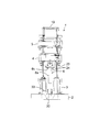
この図から明らかなように、本例の竪型射出成形機においては、竪型に構成された射出ユニット1が、竪型に構成された型開閉ユニットの最上部に位置するダイプレート2の上面に、中空のベースブラケット3を介して取り付けられている。なお、ダイプレート2の下面側には、図示しない上金型が取り付けられる。
As is apparent from this figure, in the vertical injection molding machine of this example, the upper surface of the die plate 2 in which the injection unit 1 configured in a vertical pattern is positioned at the top of the mold opening / closing unit configured in a vertical pattern. Are attached via a hollow base bracket 3. An upper mold (not shown) is attached to the lower surface side of the die plate 2.
射出ユニット1は、相対向に配置され、ダイプレート2に対して互いに所定の範囲で上下動する加熱筒保持プレート4及び直動プレート5と、加熱筒保持プレート4から吊り下げられた加熱筒ユニット6と、加熱筒ユニット6を上下動するノズルタッチ用ボールネジ機構7及びノズルタッチ用電動サーボモータ8と、加熱筒ユニット6内に回転可能かつ上下動可能に収納され、基端部が直動プレート5に回転可能に保持されたスクリュ9と、スクリュ9を回転駆動する計量用電動サーボモータ10と、直動プレート5及びスクリュ9を一体として前後進させる射出用ボールネジ機構11及び射出用電動サーボモータ12とを備えている。加熱筒ユニット6は、加熱筒6aと、その先端部に取り付けられたノズル6bと、加熱筒6aの基端部に取り付けられたホッパブロック6cとからなり、ノズル6bは、ダイプレート2に開設された加熱筒挿入孔2aを通して、図示しない上金型に開設された樹脂注入穴に押し付けられる。また、射出用ボールネジ機構11は、加熱筒保持プレート4に回転可能に取り付けられたナット体11aと、該ナット体11aに螺合されたネジ軸11bとからなる。なお、本実施形態においては、ノズルタッチ用のモータとして電動サーボモータ8を用いているが、これに代えて通常の電動モータを用いることもできる。本明細書においては、これらを総称して「ノズルタッチ用モータ」ということがある。
The injection unit 1 is arranged opposite to each other, and the heating cylinder holding plate 4 and the linear motion plate 5 that move up and down with respect to the die plate 2 within a predetermined range, and the heating cylinder unit suspended from the heating cylinder holding plate 4 6, a nozzle touch ball screw mechanism 7 that moves up and down the heating cylinder unit 6 and an electric servo motor 8 for nozzle touch, and is housed in the heating cylinder unit 6 so as to be rotatable and movable up and down, and the base end portion is a direct acting plate 5, a screw 9 rotatably held by the motor 5, a metering electric servomotor 10 that rotationally drives the screw 9, an injection ball screw mechanism 11 that moves the linear motion plate 5 and the screw 9 forward and backward, and an electric servomotor for injection 12. The heating cylinder unit 6 includes a heating cylinder 6a, a nozzle 6b attached to the distal end portion thereof, and a hopper block 6c attached to the proximal end portion of the heating cylinder 6a. The nozzle 6b is opened on the die plate 2. Through the heating cylinder insertion hole 2a, it is pressed against a resin injection hole provided in an upper mold (not shown). The injection ball screw mechanism 11 includes a nut body 11a that is rotatably attached to the heating cylinder holding plate 4, and a screw shaft 11b that is screwed into the nut body 11a. In the present embodiment, the electric servo motor 8 is used as a nozzle touch motor, but a normal electric motor may be used instead. In the present specification, these may be collectively referred to as “nozzle touch motor”.
なお、射出ユニット1に備えられる各モータ8,10,12の駆動・停止は、竪型射出成形機に備えられた制御装置21によって制御される。また、この制御装置21には表示装置22が付設されており、射出ユニット1の設定条件、駆動状況及び加熱筒保持プレート4に対する加熱筒ユニット6の着脱手順等が表示される。
The driving / stopping of the motors 8, 10, 12 provided in the injection unit 1 is controlled by a control device 21 provided in the vertical injection molding machine. In addition, a display device 22 is attached to the control device 21, and the setting conditions of the injection unit 1, the driving condition, the attaching / detaching procedure of the heating cylinder unit 6 with respect to the heating cylinder holding plate 4 and the like are displayed.
加熱筒保持プレート4には、ノズルタッチ用のボールネジ機構7のナット体7aが回転可能に保持されており、該ナット体7aには、ボールネジ機構7のネジ軸7bが螺合されている。該ボールネジ機構7は、加熱筒ユニット6を中心として120°角度間隔で3つ設けられており、各ボールネジ機構7のネジ軸7bの下端部は、ベースブラケット3の上面側にそれぞれ固定され、各ネジ軸7bの上端側は、連結ブラケット13に固定されている。本実施形態では、ボールネジ機構7のネジ軸7bには、ボールネジ機構用の螺旋溝とボールスプライン機構用の直線溝とがクロスするように形成されていて、ネジ軸7bは、ネジ軸の機能とボールスプライン軸としての機能を兼ね備えるようになっている。各ネジ軸7bは、加熱筒保持プレート4に固定されたスプライン外筒体14及び後記する直動プレート5に固定されたスプライン外筒体15に、それぞれボールスプライン結合されており、これにより、加熱筒保持プレート4及び直動プレート5は、ネジ軸7bの軸方向には移動可能で、回転は不能となる。
A nut body 7a of a ball screw mechanism 7 for nozzle touch is rotatably held on the heating cylinder holding plate 4, and a screw shaft 7b of the ball screw mechanism 7 is screwed to the nut body 7a. Three ball screw mechanisms 7 are provided at an angular interval of 120 ° with the heating cylinder unit 6 as the center. The lower ends of the screw shafts 7b of the ball screw mechanisms 7 are fixed to the upper surface side of the base bracket 3, respectively. The upper end side of the screw shaft 7 b is fixed to the connection bracket 13. In the present embodiment, the screw shaft 7b of the ball screw mechanism 7 is formed so that the spiral groove for the ball screw mechanism and the linear groove for the ball spline mechanism cross, and the screw shaft 7b has the function of the screw shaft. It also has a function as a ball spline shaft. Each screw shaft 7b is connected to a spline outer cylinder 14 fixed to the heating cylinder holding plate 4 and a spline outer cylinder 15 fixed to a linear motion plate 5 to be described later by ball spline coupling. The cylinder holding plate 4 and the linear motion plate 5 are movable in the axial direction of the screw shaft 7b and cannot be rotated.
ノズルタッチ用サーボモータ8の回転は、ボールネジ機構7のナット体7aと一体回転する被動プーリ7cに伝達され、ナット体7aが回転することで、ナット体7aと一体となって加熱筒保持プレート4が下降駆動若しくは上昇駆動される。これにより、ノズルが図示しない上金型の樹脂注入孔に当接する位置と後に説明する加熱筒交換治具と干渉しない所定の位置との間で往復駆動される。
The rotation of the nozzle touch servomotor 8 is transmitted to a driven pulley 7c that rotates integrally with the nut body 7a of the ball screw mechanism 7, and the nut body 7a rotates, so that the heating cylinder holding plate 4 is integrated with the nut body 7a. Is driven down or up. Thus, the nozzle is reciprocated between a position where the nozzle abuts a resin injection hole of the upper mold (not shown) and a predetermined position where the nozzle does not interfere with a heating cylinder replacement jig described later.
直動プレート5には、計量用電動サーボモータ10が搭載されており、該計量用電動サーボモータ10の回転は、スクリュ9と一体回転する回転部材に固定された被動プーリ16に伝達されていて、これによりスクリュ9が回転駆動されるようになっている。
The linear motion plate 5 is equipped with a metering electric servo motor 10, and the rotation of the metering electric servo motor 10 is transmitted to a driven pulley 16 fixed to a rotating member that rotates integrally with the screw 9. Thereby, the screw 9 is rotationally driven.
また、直動プレート5には、射出用電動サーボモータ12も取り付けられており、該射出用電動サーボモータ12の回転は、加熱筒保持プレート4に固定保持されたナット体11aと、該ナット体11aに螺合され、かつ直動プレート5に回転可能に保持されたネジ軸11bとから構成される射出用のボールネジ機構11を介して直動プレート5に伝達される。即ち、射出用電動サーボモータ12の回転は、ボールネジ機構11を構成するネジ軸11bと一体回転する被動プーリ17に伝達され、ネジ軸11bが回転すると、所定位置に止まっている加熱筒保持プレート4のナット体に対してネジ軸11bが直線運動し、これにより、直動プレート5及びスクリュ9が一体に下降駆動若しくは上昇駆動される。
An electric servomotor 12 for injection is also attached to the linear motion plate 5, and the rotation of the electric servomotor 12 for injection is fixed to the heating cylinder holding plate 4 and the nut body 11 a. It is transmitted to the linear motion plate 5 through an injection ball screw mechanism 11 that is constituted by a screw shaft 11b that is screwed to the linear motion plate 11 and that is rotatably held by the linear motion plate 5. That is, the rotation of the injection electric servomotor 12 is transmitted to the driven pulley 17 that rotates integrally with the screw shaft 11b that constitutes the ball screw mechanism 11, and when the screw shaft 11b rotates, the heating cylinder holding plate 4 that is stopped at a predetermined position. The screw shaft 11b is linearly moved with respect to the nut body, whereby the linear motion plate 5 and the screw 9 are integrally driven downward or upward.
かかる構成の射出ユニット1を備えた縦型射出成形機は、成形運転時には、ノズルタッチ用電動サーボモータ8を所定方向に回転駆動して、加熱筒保持プレート4を下降させ、加熱筒ユニット6の先端部に備えられたノズルを上金型の樹脂注入穴に押し付けて、この押し付け状態をノズルタッチ用電動サーボモータ8で維持させた状態におく。成形運転中の計量行程時には、計量用電動サーボモータ10を所定方向に回転させてスクリュ9を所定方向に回転駆動し、加熱筒ユニット6の基端側に供給された樹脂材料を、混練・可塑化しつつスクリュ9の先端側に送り込み、スクリュ9の先端側に溶融樹脂が貯えるにしたがってスクリュ9が直動プレート5と共に後退(上昇)させられる。そして、この際の溶融樹脂に負荷する圧力(背圧)を、射出用電動サーボモータ12により制御しつつ、スクリュ9の回転と回転に伴う後退とを実行させ、スクリュ9の先端側に1ショット分の溶融樹脂が貯えられた時点で、計量用電動サーボモータ10の回転を停止させる。また、成形運転中の射出行程時には、射出用電動サーボモータ12を所定方向に回転駆動して、スクリュ9を直動プレート5と共に急速前進(急速下降)させ、ノズル6bから型締め状態にある金型のキャビティ内に溶融樹脂を射出・充填する。
The vertical injection molding machine including the injection unit 1 having such a configuration rotates the nozzle touch electric servomotor 8 in a predetermined direction during the molding operation to lower the heating cylinder holding plate 4. The nozzle provided at the tip is pressed against the resin injection hole of the upper mold, and this pressing state is maintained by the nozzle touch electric servomotor 8. During the metering process during the molding operation, the metering electric servo motor 10 is rotated in a predetermined direction to rotationally drive the screw 9 in a predetermined direction, and the resin material supplied to the proximal end side of the heating cylinder unit 6 is kneaded and plasticized. The screw 9 is fed to the distal end side of the screw 9 while being turned, and the screw 9 is retracted (raised) together with the linear motion plate 5 as molten resin is stored on the distal end side of the screw 9. Then, while controlling the pressure (back pressure) applied to the molten resin at this time by the electric servomotor 12 for injection, the screw 9 is rotated and retracted along with the rotation, and one shot is applied to the tip side of the screw 9. When the amount of molten resin is stored, rotation of the metering electric servo motor 10 is stopped. Further, during the injection stroke during the molding operation, the electric servomotor 12 for injection is rotationally driven in a predetermined direction, and the screw 9 is rapidly moved forward (rapidly lowered) together with the linear motion plate 5, and the mold clamped from the nozzle 6b. The molten resin is injected and filled into the mold cavity.
次に、本発明に係る加熱筒交換方法の実施に適用される加熱筒交換治具30の構成を、図2及び図3を用いて説明する。
Next, the configuration of the heating cylinder replacement jig 30 applied to the implementation of the heating cylinder replacement method according to the present invention will be described with reference to FIGS.
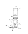
これらの図に示すように、本例の加熱筒交換治具30は、保持した加熱筒ユニット6を直線的に移送するものであって、所定形状の枠形に形成されたスライダ本体31と、該スライダ本体31に摺動自在に保持されたスライダ板32と、該スライダ板32の上面に固定された筒状の加熱筒挿入保持部33とを備えている。
As shown in these drawings, the heating cylinder replacement jig 30 of this example linearly transfers the held heating cylinder unit 6, and includes a slider body 31 formed in a frame shape having a predetermined shape, A slider plate 32 that is slidably held by the slider body 31 and a cylindrical heating tube insertion holding portion 33 that is fixed to the upper surface of the slider plate 32 are provided.
スライダ本体31は、略四角形に形成された所定サイズの下板31aと、下板31aの長辺部分に配置されたスペーサ31bと、スペーサ31bの端部間を連結する連結板31cと、当該スライダ本体31をダイプレート2に固定するための固定盤31dとを有し、これらの各部材をボルト31eを用いて一体化してなる。スライダ板32は、下板31aの上面とスペーサ31bの内面とによって画定される空間内に摺動自在に内装される摺動部32aと、摺動部32aの一端に設けられてスライダ本体31の外部に配置された把手32bとからなり、摺動部32aの上面には、加熱筒挿入保持部33が取り付けられている。加熱筒挿入保持部33としては、交換しようとする加熱筒ユニット6の先端部を容易に挿入することができ、かつ挿入された加熱筒ユニット6が過大に動揺しない程度の適度の内径を有するものが用いられる。
The slider body 31 includes a lower plate 31a of a predetermined size formed in a substantially square shape, a spacer 31b disposed on a long side portion of the lower plate 31a, a connecting plate 31c for connecting between end portions of the spacer 31b, and the slider. A fixing plate 31d for fixing the main body 31 to the die plate 2 is provided, and these members are integrated using bolts 31e. The slider plate 32 is provided at one end of the sliding portion 32a and a sliding portion 32a that is slidably mounted in a space defined by the upper surface of the lower plate 31a and the inner surface of the spacer 31b. The heating cylinder insertion holding part 33 is attached to the upper surface of the sliding part 32a. As the heating cylinder insertion / holding portion 33, a heating cylinder unit 6 to be replaced can be easily inserted at the tip, and the inserted heating cylinder unit 6 has an appropriate inner diameter so as not to be excessively shaken. Is used.
以下、上述の加熱筒交換治具30を用いた加熱筒交換方法を、図4乃至図11を用いて説明する。
Hereinafter, a heating cylinder replacement method using the above-described heating cylinder replacement jig 30 will be described with reference to FIGS. 4 to 11.
作業者が図示しない操作盤を操作して竪型射出成形機を起動すると、竪型射出成形機に備えられた制御装置21が立ち上がり、表示装置22には図示しない所定のメニュー画面が表示される。加熱筒ユニット6の交換時には、このメニュー画面から「交換」を選択する。これにより表示装置22には、図5に示す交換画面40が表示される。交換画面40には、型開閉位置、型厚、ノズル、型締力、スクリュ抜き前進、スクリュ抜き後退、交換型開1、交換型開2、交換型閉、エジェクタ前進、エジェクタ後退の各表示欄が表示される。また、反復自動パージとして、自動パージの位置、速度、回転速度、圧力、回数の各表示欄も表示される。さらに、ファンクションボタンとして、自動増締ボタン、自動型厚移動ボタン、加熱筒交換新規ボタン、加熱筒交換継続ボタン、自動原点出しボタンも表示される。表示装置22の表示画面が交換画面40に切り替わった後、作業者が交換画面40に表示された加熱筒交換新規ボタンを押すと、交換画面40には、加熱筒取り外し又は加熱筒セットの選択画面が現れる。ここで、作業者が加熱筒取り外しを選択すると、表示装置22には、図5に示す加熱筒取り外し画面41が表示される。作業者は、この表示装置22に表示された加熱筒取り外し画面41を参照しながら、加熱筒ユニット6の取り外し作業を実行する。
When the operator operates the operation panel (not shown) to start the vertical injection molding machine, the control device 21 provided in the vertical injection molding machine starts up and a predetermined menu screen (not shown) is displayed on the display device 22. . When exchanging the heating cylinder unit 6, “exchange” is selected from this menu screen. Thereby, the replacement screen 40 shown in FIG. 5 is displayed on the display device 22. On the replacement screen 40, display fields for a mold opening / closing position, a mold thickness, a nozzle, a clamping force, a screw advance, a screw retract, an exchange mold open 1, an exchange mold open 2, an exchange mold closed, an ejector advance, and an ejector retract Is displayed. In addition, as repetitive automatic purging, display columns for automatic purging position, speed, rotational speed, pressure, and number of times are also displayed. In addition, an automatic tightening button, an automatic mold thickness moving button, a heating tube replacement new button, a heating tube replacement continuation button, and an automatic home search button are also displayed as function buttons. After the display screen of the display device 22 is switched to the replacement screen 40, when the operator presses the heating tube replacement new button displayed on the replacement screen 40, the replacement screen 40 displays a selection screen for removing the heating tube or setting the heating tube. Appears. Here, when the operator selects the removal of the heating cylinder, the heating cylinder removal screen 41 shown in FIG. 5 is displayed on the display device 22. The worker performs the removal operation of the heating cylinder unit 6 while referring to the heating cylinder removal screen 41 displayed on the display device 22.
即ち、作業者は、加熱筒取り外し画面41の第1番目に表示された「1.スクリュ、ヒータ、ノズル、冷却ホースを取り外しましたか?」の記載にしたがってスクリュ、ヒータ、ノズル及び冷却ホースの取り外し作業を行い、作業完了後、当該記載欄の右側に表示されたチェック欄にチェックを入れる。
That is, the worker removes the screw, heater, nozzle and cooling hose according to the description of “1. Did you remove the screw, heater, nozzle and cooling hose?” Displayed on the first screen of the heating cylinder removal screen 41. Perform the work, and after completing the work, check the check box displayed on the right side of the entry field.
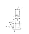
次いで、作業者は、加熱筒取り外し画面41の第2番目に表示された「2.加熱筒交換治具をセットし、挿入しましたか?」の記載にしたがってダイプレート2に対する加熱筒交換治具30の取付作業を行い、図7乃至図11に示すように、加熱筒挿入保持部33を加熱筒ユニット6の直下に配置する。作業完了後、当該記載欄の右欄に表示されたチェック欄にチェックを入れる。
Next, the worker follows the description of “2. Is the heating cylinder replacement jig set and inserted?” Displayed on the second display of the heating cylinder removal screen 41, and the heating cylinder replacement jig for the die plate 2. As shown in FIGS. 7 to 11, the heating cylinder insertion holding portion 33 is disposed immediately below the heating cylinder unit 6. After completing the work, check the check box displayed in the right column of the entry column.
次いで、作業者は、加熱筒取り外し画面41の第3番目に表示された「3.ノズルがスライダタッチ手前の所定の位置まで前進します。所定の位置に到達後、モータが自動で停止します。」の記載を確認し、その記載欄の右側に表示された開始ボタンを押す。これにより、ノズルタッチ用電動サーボモータ8が所定の方向に回転し、図8に示すように、加熱筒ユニット6の先端が、加熱筒挿入保持部33の底面に当接しない所定位置まで下降する。
Next, the operator displays “3. Nozzle moves forward to a predetermined position before touching the slider. The motor automatically stops after reaching the predetermined position. Confirm the description of "." And press the start button displayed on the right side of the description column. As a result, the nozzle touch electric servomotor 8 rotates in a predetermined direction, and as shown in FIG. 8, the tip of the heating cylinder unit 6 is lowered to a predetermined position where it does not contact the bottom surface of the heating cylinder insertion holding portion 33. .
次いで、作業者は、加熱筒取り外し画面41の第4番目に表示された「4.ボルトを取り外して下さい。」の記載を確認し、加熱筒保持プレート4に加熱筒ユニット6を固定しているボルト23を取り外す。加熱筒ユニット6は、ボルト23を緩めるに従って徐々に下降し、図9に示すように、その先端部が加熱筒挿入保持部33の底面に静かに当接される。
Next, the operator confirms the description of “4. Remove the bolt” displayed on the fourth of the heating cylinder removal screen 41, and fixes the heating cylinder unit 6 to the heating cylinder holding plate 4. Remove the bolt 23. The heating cylinder unit 6 gradually descends as the bolt 23 is loosened, and its tip end is gently brought into contact with the bottom surface of the heating cylinder insertion holder 33 as shown in FIG.
次いで、作業者は、加熱筒取り外し画面41の第5番目に表示された「5.モータ電源を入れて下さい。」の記載にしたがって、作業者が竪型射出成形機に備えられた操作盤を操作し、モータ電源をオンに切り換える。これにより、ノズルタッチ用電動サーボモータ8の再度の起動停止が可能になる。
Next, the operator follows the description of “5. Turn on the motor power” displayed on the fifth screen of the heating cylinder removal screen 41, and the operator installs the operation panel provided in the vertical injection molding machine. Operate and switch on the motor power. As a result, it is possible to restart and stop the nozzle touch electric servomotor 8 again.
次いで、作業者は、加熱筒取り外し画面41の第6番目に表示された「6.交換モードにして下さい。」の記載を確認し、作業者が竪型射出成形機に備えられた操作盤を操作して、ノズルタッチ用電動サーボモータ8の駆動モードを交換モードに切り換える。
Next, the operator confirms the description of “6. Change to the replacement mode” displayed on the sixth screen of the heating cylinder removal screen 41, and the operator installs the operation panel provided in the vertical injection molding machine. By operating, the drive mode of the nozzle touch electric servomotor 8 is switched to the replacement mode.
次いで、作業者は、加熱筒取り外し画面41の第7番目に表示された「7.加熱筒交換モード・継続ボタンを押して下さい。」の記載を確認し、作業者が表示装置22に表示された交換画面40の加熱筒交換継続ボタンを押す。これにより、ノズルタッチ用電動サーボモータ8を逆転して、加熱筒保持プレート4を上昇させることが可能になる。
Next, the operator confirmed the description of “7. Press the heating tube replacement mode / continue button” displayed on the seventh display on the heating tube removal screen 41, and the operator was displayed on the display device 22. Press the heating tube replacement continuation button on the replacement screen 40. Thereby, it becomes possible to reverse the nozzle touch electric servomotor 8 and raise the heating cylinder holding plate 4.
次いで、作業者は、加熱筒取り外し画面41の第8番目に表示された「8.加熱筒抑えボルトは全て抜きましたか?」の記載にしたがって、全てのボルト23が抜かれていることを確認する。当該作業の完了後、第8番目の記載の右側に表示されたチェック欄にチェックを入れる。
Next, the operator confirms that all the bolts 23 have been removed according to the description “8. Have you removed all the heating cylinder holding bolts?” Displayed on the eighth screen of the heating cylinder removal screen 41. . After completion of the work, check the check box displayed on the right side of the eighth description.
次いで、作業者は、加熱筒取り外し画面41の第9番目に表示された「9.ノズル後退限まで後退します。よろしいか?後退限位置到達後、自動でモータが停止します。」の記載を確認し、その記載欄の右側に表示された開始ボタンを押す。これにより、ノズルタッチ用電動サーボモータ8が逆転して加熱筒保持プレート4が後退限位置まで上昇し、図10に示すように、加熱筒ユニット6の基端部と加熱筒保持プレート4の下面との間に所要のクリアランスdが形成される。
Next, the operator displays the ninth display on the heating cylinder removal screen 41 “9. Retreat to the nozzle retract limit. Are you sure? The motor automatically stops after reaching the retract limit position”. And press the start button displayed on the right side of the entry field. As a result, the nozzle touch electric servomotor 8 reverses and the heating cylinder holding plate 4 rises to the retreat limit position, and as shown in FIG. 10, the base end of the heating cylinder unit 6 and the lower surface of the heating cylinder holding plate 4 A required clearance d is formed between the two.
最後に、作業者は、加熱筒取り外し画面41の第10番目に表示された「10.完全にスライダを引き出し、加熱筒を取り外して下さい。」の記載を確認し、加熱筒交換治具30の把手32bを持って、図11に示すようにスライダ板32をスライダ本体31に沿って手前側に引き出し、加熱筒挿入保持部33に保持された加熱筒ユニット6を、竪型射出成形機の側方部分に引き出す。これにより、例えばチェーンブロック等を用いて、加熱筒ユニット6を所定の保管場所に移送することが可能になる。
Finally, the operator confirms the description of “10. Pull out the slider completely and remove the heating cylinder” displayed on the tenth of the heating cylinder removal screen 41, and Holding the handle 32b, as shown in FIG. 11, the slider plate 32 is pulled out along the slider body 31, and the heating cylinder unit 6 held by the heating cylinder insertion holding portion 33 is moved to the vertical injection molding machine side. Pull out to the side. Thereby, it becomes possible to transfer the heating cylinder unit 6 to a predetermined storage place using, for example, a chain block.
一方、加熱筒保持プレート4に加熱筒ユニット6を取り付ける際には、表示装置22に表示された交換画面40(図4参照)の加熱筒交換新規ボタンを押して、交換画面40に加熱筒取り外し又は加熱筒セットの選択画面を表示した後、加熱筒セットを選択する。これにより、表示装置22には、図6に示す加熱筒セット画面42が表示されるので、作業者は、当該加熱筒セット画面42を参照しながら加熱筒ユニット6のセット作業を実行する。
On the other hand, when the heating cylinder unit 6 is attached to the heating cylinder holding plate 4, the heating cylinder replacement new button on the replacement screen 40 (see FIG. 4) displayed on the display device 22 is pressed to remove the heating cylinder on the replacement screen 40 or After displaying the selection screen of the heating cylinder set, the heating cylinder set is selected. As a result, the display unit 22 displays the heating tube setting screen 42 shown in FIG. 6, so that the operator performs the setting operation of the heating tube unit 6 while referring to the heating tube setting screen 42.
即ち、作業者は、加熱筒セット画面42の第1番目に表示された「1.モータを入れて下さい。」の記載を確認し、竪型射出成形機に備えられた操作盤を操作して、モータ電源をオンに切り換える。これにより、ノズルタッチ用電動サーボモータ8の起動停止が可能になる。
That is, the operator confirms the description of “1. Turn on the motor” displayed on the first screen of the heating tube setting screen 42 and operates the operation panel provided in the vertical injection molding machine. Switch on the motor power. As a result, the nozzle touch electric servo motor 8 can be started and stopped.
次いで、作業者は、加熱筒セット画面42の第2番目に表示された「2.交換モードにして下さい。」の記載を確認し、作業者が竪型射出成形機に備えられた操作盤を操作して、ノズルタッチ用電動サーボモータ8の駆動モードを交換モードに切り換える。
Next, the operator confirms the description of “2. Change to the replacement mode” displayed on the second screen of the heating cylinder setting screen 42, and the operator installs the operation panel provided in the vertical injection molding machine. By operating, the drive mode of the nozzle touch electric servomotor 8 is switched to the replacement mode.
次いで、作業者は、加熱筒セット画面42の第3番目に表示された「3.ノズル後退限まで後退します。よろしいか?」の記載を確認し、その記載欄の右側に表示された開始ボタンを押す。これにより、ノズルタッチ用電動サーボモータ8が逆転して加熱筒保持プレート4が後退限位置まで上昇する。
Next, the operator confirms the description of “3. Retreat to the nozzle retreat limit.” Displayed on the third display on the heating tube setting screen 42, and the start displayed on the right side of the description column. I press the button. As a result, the nozzle touch electric servomotor 8 reverses and the heating cylinder holding plate 4 rises to the retreat limit position.
次いで、作業者は、加熱筒セット画面42の第4番目に表示された「4.ホッパブロックと加熱筒をボルトで固定しましたか?」の記載にしたがって、加熱筒6aとホッパブロック6bとがボルト24で結合されていることを確認した後、その記載欄の右側に表示されたチェック欄にチェックを入れる。
Next, the worker follows the description of “4. Did you fix the hopper block and the heating cylinder with bolts” displayed on the fourth of the heating cylinder setting screen 42, and the heating cylinder 6a and the hopper block 6b are After confirming that the bolts 24 are connected, a check is displayed in the check column displayed on the right side of the description column.
次いで、作業者は、加熱筒セット画面42の第5番目に表示された「5.スクリュ、ヒータ、ノズルは、取り外してますか?」の記載にしたがってスクリュ、ヒータ及びノズルが取り外されていることを確認した後、その記載欄の右側に表示されたチェック欄にチェックを入れる。
Next, the operator has removed the screw, heater and nozzle according to the description of “5. Are screws, heaters and nozzles removed?” Displayed on the fifth screen of the heating tube setting screen 42. After confirming, check the check box displayed on the right side of the entry field.
次いで、作業者は、加熱筒セット画面42の第6番目に表示された「6.加熱筒交換治具をセットし、引き出した状態にしましたか?」の記載にしたがって、ダイプレート2に対する加熱筒交換治具30の取付作業を行い、加熱筒挿入保持部33を竪型射出成形機の側方部分に引き出す。当該作業の完了後、加熱筒セット画面42に表示されたチェック欄にチェックを入れる。
Next, the operator heats the die plate 2 in accordance with the description of “6. Did you set the heating cylinder replacement jig and pull it out?” Displayed on the sixth of the heating cylinder setting screen 42. The cylinder replacement jig 30 is attached, and the heating cylinder insertion holding portion 33 is pulled out to the side portion of the vertical injection molding machine. After completion of the work, a check is put in the check column displayed on the heating cylinder setting screen 42.
次いで、作業者は、加熱筒セット画面42の第7番目に表示された「7.加熱筒を加熱筒交換治具に正常にセットし、挿入しましたか?」の記載にしたがって、加熱筒交換治具30の加熱筒挿入保持部33に、ホッパブロックと一体化された加熱筒ユニット6の先端部を挿入する。当該作業の完了後、加熱筒セット画面42に表示されたチェック欄にチェックを入れる。
Next, the operator replaces the heating cylinder in accordance with the description of “7. Did you correctly set and insert the heating cylinder in the heating cylinder replacement jig” displayed on the seventh display on the heating cylinder setting screen 42. The tip of the heating cylinder unit 6 integrated with the hopper block is inserted into the heating cylinder insertion holding portion 33 of the jig 30. After completion of the work, a check is put in the check column displayed on the heating cylinder setting screen 42.
次いで、作業者は、加熱筒セット画面42の第8番目に表示された「8.ノズルがスライダタッチ手前の所定の位置まで前進します。所定の位置に到達後、モータが自動で停止します。」の記載を確認し、その記載欄の右側に表示された開始ボタンを押す。これにより、ノズルタッチ用電動サーボモータ8が所定の方向に回転し、加熱筒保持プレート4が加熱筒ユニット6の取り付けが可能になる所定位置まで下降する(図8参照)。
Next, the operator displays “8. Nozzle moves forward to a predetermined position before touching the slider. The motor automatically stops after reaching the predetermined position. Confirm the description of "." And press the start button displayed on the right side of the description column. As a result, the nozzle touch electric servomotor 8 rotates in a predetermined direction, and the heating cylinder holding plate 4 is lowered to a predetermined position where the heating cylinder unit 6 can be attached (see FIG. 8).
次いで、作業者は、加熱筒セット画面42の第9番目に表示された「9.ボルトを取り付けて下さい。」の記載にしたがって、加熱筒保持プレート4に対するホッパブロックの取付作業を行う。
Next, the worker performs the hopper block mounting operation on the heating cylinder holding plate 4 in accordance with the description “9. Attach bolts” displayed on the ninth of the heating cylinder setting screen 42.
次いで、作業者は、加熱筒セット画面42の第10番目に表示された「10.モータ電源を入れて下さい。」の記載にしたがって竪型射出成形機に備えられた操作盤を操作し、モータ電源をオンに切り換える。これにより、ノズルタッチ用電動サーボモータ8の再度の起動停止が可能になる。
Next, the operator operates the operation panel provided in the vertical injection molding machine in accordance with the description of “10. Turn on the motor power” displayed on the 10th of the heating cylinder setting screen 42, and the motor Turn the power on. As a result, it is possible to restart and stop the nozzle touch electric servomotor 8 again.
次いで、作業者は、加熱筒セット画面42の第11番目に表示された「11.交換モードにして下さい。」の記載を確認し、竪型射出成形機に備えられた操作盤を操作して、ノズルタッチ用電動サーボモータ8の駆動モードを交換モードに切り換える。
Next, the operator confirms the description of “11. Enter the replacement mode” displayed on the eleventh of the heating cylinder setting screen 42 and operates the operation panel provided in the vertical injection molding machine. The drive mode of the nozzle touch electric servomotor 8 is switched to the replacement mode.
次いで、作業者は、加熱筒セット画面42の第12番目に表示された「12.加熱筒交換モード・継続ボタンを押して下さい。」の記載を確認し、表示装置22に表示された交換画面40の加熱筒交換継続ボタンを押す。これにより、ノズルタッチ用電動サーボモータ8を逆転して、加熱筒保持プレート4を上昇させることが可能になる。
Next, the operator confirms the description of “12. Press the heating cylinder replacement mode / continuation button” displayed on the twelfth of the heating cylinder setting screen 42, and the replacement screen 40 displayed on the display device 22. Press the heating tube replacement continuation button. Thereby, it becomes possible to reverse the nozzle touch electric servomotor 8 and raise the heating cylinder holding plate 4.
次いで、作業者は、加熱筒セット画面42の第13番目に表示された「13.加熱筒押さえボルトを全て取り付けましたか?」の記載にしたがって、ボルト23により加熱筒保持プレート4にホッパブロック6bが締結されていることを確認した後、その記載欄の右側に表示されたチェック欄にチェックを入れる。
Next, the operator follows the description “13. Have you installed all the heating cylinder holding bolts?” Displayed on the thirteenth of the heating cylinder setting screen 42 with the bolt 23 to the hopper block 6b on the heating cylinder holding plate 4. After confirming that has been concluded, check the check box displayed on the right side of the entry field.
次いで、作業者は、加熱筒セット画面42の第14番目に表示された「14.ノズル後退限まで後退します。後退限位置到達後、自動でモータが停止します。」の記載を確認し、その記載欄の右側に表示された開始ボタンを押す。これにより、ノズルタッチ用電動サーボモータ8が所定の方向に回転し、加熱筒交換治具30の取り外しが可能になる所定位置まで上昇する(図7参照)。
Next, the operator confirms the description of “14. Retreat to the nozzle retract limit. The motor automatically stops after reaching the retract limit position” displayed on the 14th screen of the heating cylinder setting screen 42. , Press the start button displayed on the right side of the entry field. As a result, the nozzle touch electric servomotor 8 rotates in a predetermined direction and rises to a predetermined position where the heating tube replacement jig 30 can be removed (see FIG. 7).
最後に、作業者は、加熱筒セット画面42の第15番目に表示された「15.モータを停止後、加熱筒交換治具を取り外して下さい。」の記載にしたがって、ダイプレート2から加熱筒交換治具30を取り外す。
Finally, the operator follows the description of “15. Remove the heating cylinder replacement jig after stopping the motor” displayed on the fifteenth heating cylinder setting screen 42, from the die plate 2. Remove the replacement jig 30.
本実施形態に係る加熱筒交換方法は、加熱筒保持プレート4に対する加熱筒ユニット6の着脱手順を表示装置22に表示し、作業者がこの表示装置22に表示された着脱手順に従って加熱筒ユニット6の着脱作業を行うので、特別な知識や熟練がない作業者でも加熱筒ユニット6の交換が可能になる。また、加熱筒ユニット6の交換作業を、加熱筒交換治具30を用いて行うので、作業者は大重量の加熱筒ユニット6を加熱筒交換治具30にて保持することができ、加熱筒ユニット6を人力で支える必要がないので、加熱筒ユニット6の着脱作業を容易かつ安全なものにすることができる。
In the heating cylinder replacement method according to the present embodiment, a procedure for attaching / detaching the heating cylinder unit 6 to / from the heating cylinder holding plate 4 is displayed on the display device 22, and an operator follows the attaching / detaching procedure displayed on the display device 22. Therefore, even an operator who does not have special knowledge or skill can replace the heating cylinder unit 6. Further, since the replacement operation of the heating cylinder unit 6 is performed using the heating cylinder replacement jig 30, the operator can hold the heavy heating cylinder unit 6 with the heating cylinder replacement jig 30, and the heating cylinder Since it is not necessary to support the unit 6 manually, the attaching / detaching operation of the heating cylinder unit 6 can be easily and safely performed.
なお、前記実施形態においては、加熱筒6aとホッパブロック6bとを一体化してなる加熱筒ユニット6の交換方法について説明したが、本発明の要旨はこれに限定されるものではなく、加熱筒6aを直接加熱筒保持プレート4に取り付けてなるタイプの竪型射出成形機においては、加熱筒6aの交換方法にそのまま応用することができる。
In addition, in the said embodiment, although the replacement | exchange method of the heating cylinder unit 6 formed by integrating the heating cylinder 6a and the hopper block 6b was demonstrated, the summary of this invention is not limited to this, The heating cylinder 6a In a vertical injection molding machine of a type in which is directly attached to the heating cylinder holding plate 4, it can be directly applied to the method of replacing the heating cylinder 6a.
1 射出ユニット
2 ダイプレート
3 ベースブラケット
4 加熱筒保持プレート
5 直動プレート
6 加熱筒ユニット
6a 加熱筒
6b ホッパブロック
7 ノズルタッチ用ボールネジ機構
7a ナット体
7b ネジ軸
8 ノズルタッチ用電動サーボモータ
9 スクリュ
10 計量用電動サーボモータ
11 射出用ボールネジ機構
12 射出用電動サーボモータ
13 連結ブラケット
14 スプライン外筒体
15 スプライン外筒体
16 回転部材
17 被動プーリ
21 制御装置
22 表示装置
30 加熱筒交換治具
31 スライダ本体
32 スライダ板
33 加熱筒挿入保持部 DESCRIPTION OFSYMBOLS 1 Injection unit 2 Die plate 3 Base bracket 4 Heating cylinder holding plate 5 Direct acting plate 6 Heating cylinder unit 6a Heating cylinder 6b Hopper block 7 Nozzle touch ball screw mechanism 7a Nut body 7b Screw shaft 8 Nozzle touch electric servo motor 9 Screw 10 Electric Servo Motor for Weighing 11 Ball Screw Mechanism for Injection 12 Electric Servo Motor for Injection 13 Connecting Bracket 14 Spline Outer Cylinder 15 Spline Outer Cylinder 16 Rotating Member 17 Driven Pulley 21 Controller 22 Display Device 30 Heating Cylinder Replacement Jig 31 Slider Body 32 Slider plate 33 Heating tube insertion holder
2 ダイプレート
3 ベースブラケット
4 加熱筒保持プレート
5 直動プレート
6 加熱筒ユニット
6a 加熱筒
6b ホッパブロック
7 ノズルタッチ用ボールネジ機構
7a ナット体
7b ネジ軸
8 ノズルタッチ用電動サーボモータ
9 スクリュ
10 計量用電動サーボモータ
11 射出用ボールネジ機構
12 射出用電動サーボモータ
13 連結ブラケット
14 スプライン外筒体
15 スプライン外筒体
16 回転部材
17 被動プーリ
21 制御装置
22 表示装置
30 加熱筒交換治具
31 スライダ本体
32 スライダ板
33 加熱筒挿入保持部 DESCRIPTION OF
Claims (5)
- 下面側に上金型が取り付けられたダイプレートと、該ダイプレートに対して上下動可能に備えられた加熱筒保持プレートと、該加熱筒保持プレートを上下動させるノズルタッチ用モータと、前記加熱筒保持プレートに上端部が着脱可能に保持された加熱筒と、該加熱筒内に回転可能かつ上下動可能に収納されたスクリュと、該スクリュを回転駆動する計量用電動サーボモータと、前記ダイプレートに対して上下動可能に備えられ、前記スクリュの上端部を着脱可能に保持する直動プレートと、該直動プレートを介して前記スクリュを上下動させる射出用電動サーボモータと、前記各モータの駆動を制御する制御装置と、所要の表示画面を適宜表示可能な表示装置とを備えた竪型射出成形機の加熱筒交換方法において、
前記加熱筒の着脱作業を行う際、前記制御装置は、前記表示装置に、前記ノズルタッチ用モータの駆動手順と、前記ダイプレートに対する加熱筒交換治具の着脱手順と、前記加熱筒交換治具への前記加熱筒の保持手順と、前記加熱筒交換治具に保持された前記加熱筒の移送手順とを含む、前記加熱筒保持プレートに対する前記加熱筒の着脱作業手順を表示し、
作業者は、この表示装置に表示された着脱作業手順にしたがって、前記加熱筒保持プレートに対する前記加熱筒の着脱作業を行うことを特徴とする竪型射出成形機の加熱筒交換方法。 A die plate having an upper mold attached to the lower surface side, a heating cylinder holding plate that is movable up and down relative to the die plate, a nozzle touch motor that moves the heating cylinder holding plate up and down, and the heating A heating cylinder whose upper end is detachably held by a cylinder holding plate, a screw housed in the heating cylinder so as to be rotatable and movable up and down, an electric servomotor for weighing that rotationally drives the screw, and the die A linear motion plate which is provided so as to be movable up and down with respect to the plate and detachably holds an upper end portion of the screw; an electric servomotor for injection which moves the screw up and down via the linear motion plate; and the motors In a heating cylinder replacement method for a vertical injection molding machine, comprising a control device for controlling the driving of and a display device capable of appropriately displaying a required display screen.
When performing the attaching / detaching operation of the heating cylinder, the control device, on the display device, drives the nozzle touch motor, attaches / detaches the heating cylinder replacement jig to / from the die plate, and the heating cylinder replacement jig. Including a procedure for holding the heating cylinder to the heating cylinder and a procedure for transferring the heating cylinder held by the heating cylinder replacement jig.
The method of replacing a heating cylinder of a vertical injection molding machine, wherein an operator performs an attaching / detaching operation of the heating cylinder with respect to the heating cylinder holding plate according to an attaching / detaching operation procedure displayed on the display device. - 前記加熱筒交換治具は、前記ダイプレートの上面にボルト締結されるスライダ本体と、該スライダ本体に摺動可能に備えられたスライダ板と、該スライダ板の上面に固定された筒状の加熱筒挿入保持部とを有することを特徴とする請求項1に記載の竪型射出成形機の加熱筒交換方法。 The heating cylinder replacement jig includes a slider body bolted to the upper surface of the die plate, a slider plate slidably provided on the slider body, and a cylindrical heating fixed to the upper surface of the slider plate. A heating cylinder replacement method for a vertical injection molding machine according to claim 1, further comprising a cylinder insertion holding portion.
- 前記加熱筒保持プレートに対する前記加熱筒の取り付け時には、竪型射出成形機の側方に引き出された前記加熱筒挿入保持部に前記加熱筒の先端部を挿入した後、前記スライダ板を前記スライダ本体に対して摺動させて、前記加熱筒挿入保持部に保持された前記加熱筒を前記加熱筒保持プレートの下方の所定位置まで移送し、
前記加熱筒保持プレートからの前記加熱筒の取り外し時には、前記加熱筒保持プレートから取り外された前記加熱筒の先端部を前記加熱筒挿入保持部に挿入した後、前記スライダ板を前記スライダ本体に対して摺動させて、前記加熱筒挿入保持部に保持された前記加熱筒を竪型射出成形機の側方の所定位置まで移送することを特徴とする請求項2に記載の竪型射出成形機の加熱筒交換方法。 When the heating cylinder is attached to the heating cylinder holding plate, the tip of the heating cylinder is inserted into the heating cylinder insertion holding part pulled out to the side of the vertical injection molding machine, and then the slider plate is moved to the slider body. The heating cylinder held in the heating cylinder insertion holding portion, and transferred to a predetermined position below the heating cylinder holding plate,
When removing the heating cylinder from the heating cylinder holding plate, the tip of the heating cylinder removed from the heating cylinder holding plate is inserted into the heating cylinder insertion holding section, and then the slider plate is attached to the slider body. 3. A vertical injection molding machine according to claim 2, wherein the heating cylinder held by the heating cylinder insertion holder is transferred to a predetermined position on the side of the vertical injection molding machine. How to replace the heating cylinder. - 前記制御装置は、作業者からの前記ノズルタッチ用モータの駆動指令を受けたとき、前記ノズルタッチ用モータの駆動を制御し、前記加熱筒の先端部を前記加熱筒交換治具と干渉しない適宜の位置まで上昇又は下降させ、当該適宜の位置で停止させることを特徴とする請求項1乃至請求項3のいずれか1項に記載の竪型射出成形機の加熱筒交換方法。 The control device controls driving of the nozzle touch motor when receiving an instruction for driving the nozzle touch motor from an operator, and appropriately controls the front end of the heating cylinder to not interfere with the heating cylinder replacement jig. The heating cylinder replacement method for a vertical injection molding machine according to any one of claims 1 to 3, wherein the vertical cylinder is raised or lowered to a position and stopped at the appropriate position.
- 竪型射出成形機に備えられたダイプレートの上面にボルト締結されるスライダ本体と、該スライダ本体に摺動可能に備えられたスライダ板と、該スライダ板の上面に固定された筒状の加熱筒挿入保持部とを有することを特徴とする加熱筒交換治具。 A slider body bolted to the upper surface of a die plate provided in the vertical injection molding machine, a slider plate slidably provided on the slider body, and a cylindrical heating fixed to the upper surface of the slider plate A heating cylinder exchanging jig having a cylinder insertion holding portion.
Priority Applications (1)
| Application Number | Priority Date | Filing Date | Title |
|---|---|---|---|
| CN201280006752.8A CN103347673B (en) | 2011-01-28 | 2012-01-19 | The cartridge heater replacing options of vertical type injection molding machine and cartridge heater change fixture |
Applications Claiming Priority (2)
| Application Number | Priority Date | Filing Date | Title |
|---|---|---|---|
| JP2011016642A JP5631228B2 (en) | 2011-01-28 | 2011-01-28 | Heating tube replacement method and heating tube replacement jig for vertical injection molding machine |
| JP2011-016642 | 2011-01-28 |
Publications (1)
| Publication Number | Publication Date |
|---|---|
| WO2012102169A1 true WO2012102169A1 (en) | 2012-08-02 |
Family
ID=46580741
Family Applications (1)
| Application Number | Title | Priority Date | Filing Date |
|---|---|---|---|
| PCT/JP2012/051094 WO2012102169A1 (en) | 2011-01-28 | 2012-01-19 | Heating sleeve exchange method and heating sleeve exchange tool for vertical injection molding machine |
Country Status (3)
| Country | Link |
|---|---|
| JP (1) | JP5631228B2 (en) |
| CN (1) | CN103347673B (en) |
| WO (1) | WO2012102169A1 (en) |
Cited By (1)
| Publication number | Priority date | Publication date | Assignee | Title |
|---|---|---|---|---|
| CN113118392A (en) * | 2021-04-14 | 2021-07-16 | 苏州三信机器制造有限公司 | Intelligent coring control method, device and system for core making workshop |
Families Citing this family (1)
| Publication number | Priority date | Publication date | Assignee | Title |
|---|---|---|---|---|
| JP5745906B2 (en) * | 2011-03-30 | 2015-07-08 | 東洋機械金属株式会社 | Vertical injection molding machine |
Citations (4)
| Publication number | Priority date | Publication date | Assignee | Title |
|---|---|---|---|---|
| JPH0259914U (en) * | 1988-10-24 | 1990-05-01 | ||
| JP3696754B2 (en) * | 1999-06-11 | 2005-09-21 | 株式会社日本製鋼所 | Desorption guide mechanism and desorption guide mechanism for plasticizing unit of vertical injection molding machine |
| JP2007069571A (en) * | 2005-09-09 | 2007-03-22 | Toyo Mach & Metal Co Ltd | Controlling method for whole height in vertical injection molding machine |
| JP2010105330A (en) * | 2008-10-31 | 2010-05-13 | Fanuc Ltd | Controller of injection molding machine with production change-over function |
Family Cites Families (3)
| Publication number | Priority date | Publication date | Assignee | Title |
|---|---|---|---|---|
| CN2905412Y (en) * | 2006-03-14 | 2007-05-30 | 华东理工大学 | Screw-bolt extruder having mobile heating cartridge |
| CN101746036A (en) * | 2008-12-09 | 2010-06-23 | 上海金发科技发展有限公司 | Device for replacing screw tube of plastic extruding machine |
| CN101791851A (en) * | 2010-03-19 | 2010-08-04 | 昆山科信橡塑机械有限公司 | Push-pull double-screw extruder |
-
2011
- 2011-01-28 JP JP2011016642A patent/JP5631228B2/en not_active Expired - Fee Related
-
2012
- 2012-01-19 WO PCT/JP2012/051094 patent/WO2012102169A1/en active Application Filing
- 2012-01-19 CN CN201280006752.8A patent/CN103347673B/en not_active Expired - Fee Related
Patent Citations (4)
| Publication number | Priority date | Publication date | Assignee | Title |
|---|---|---|---|---|
| JPH0259914U (en) * | 1988-10-24 | 1990-05-01 | ||
| JP3696754B2 (en) * | 1999-06-11 | 2005-09-21 | 株式会社日本製鋼所 | Desorption guide mechanism and desorption guide mechanism for plasticizing unit of vertical injection molding machine |
| JP2007069571A (en) * | 2005-09-09 | 2007-03-22 | Toyo Mach & Metal Co Ltd | Controlling method for whole height in vertical injection molding machine |
| JP2010105330A (en) * | 2008-10-31 | 2010-05-13 | Fanuc Ltd | Controller of injection molding machine with production change-over function |
Cited By (1)
| Publication number | Priority date | Publication date | Assignee | Title |
|---|---|---|---|---|
| CN113118392A (en) * | 2021-04-14 | 2021-07-16 | 苏州三信机器制造有限公司 | Intelligent coring control method, device and system for core making workshop |
Also Published As
| Publication number | Publication date |
|---|---|
| CN103347673A (en) | 2013-10-09 |
| JP5631228B2 (en) | 2014-11-26 |
| CN103347673B (en) | 2015-11-25 |
| JP2012153110A (en) | 2012-08-16 |
Similar Documents
| Publication | Publication Date | Title |
|---|---|---|
| US7770626B2 (en) | Method and apparatus for spraying release agent in die casting machine | |
| JP5631228B2 (en) | Heating tube replacement method and heating tube replacement jig for vertical injection molding machine | |
| EP3590678B1 (en) | Injection molding machine | |
| JP2001038762A (en) | Turning device for motor-operated injection molding machine | |
| JP2008105301A (en) | Injection molding machine | |
| CN110315702B (en) | Control device for injection molding machine and control method for injection molding machine | |
| JP5888738B2 (en) | Cleaning method | |
| JP5069502B2 (en) | Injection molding machine | |
| JP4977500B2 (en) | Injection molding machine | |
| JP2011161679A (en) | Screw-type injection device and method of disassembling/assembling the same | |
| JP6791795B2 (en) | Injection molding machine | |
| CN110653604A (en) | Military rotating head assembling equipment for unlocking coded lock tool | |
| JP2006076229A (en) | Plasticizing device-attaching method of on-line blend injection molding machine | |
| CN106401507B (en) | A kind of magnetic force rotation oil well pipe wrench and its control system | |
| JP4690826B2 (en) | Injection molding machine | |
| JP6848586B2 (en) | 2-plate injection device and screw extraction method | |
| CN216579245U (en) | High accuracy hot melt machine based on ultrasonic vibration | |
| JP6183708B2 (en) | Clamping device | |
| CN219006901U (en) | Tubular injection molding clamping equipment | |
| CN116619754B (en) | Building construction pipeline installation auxiliary device | |
| JP2022153056A (en) | Vertical injection molding machine, heating cylinder replacement jig, and heating cylinder replacement method for vertical injection molding machine | |
| JP4755463B2 (en) | Injection molding machine | |
| JP3997435B1 (en) | Injection apparatus for vertical injection molding machine and control method for vertical injection molding machine | |
| CN220881211U (en) | Automatic welding positioner device | |
| KR100958973B1 (en) | Apparatus For Inserting A Top Nozzle For A Ladle |
Legal Events
| Date | Code | Title | Description |
|---|---|---|---|
| 121 | Ep: the epo has been informed by wipo that ep was designated in this application |
Ref document number: 12738766 Country of ref document: EP Kind code of ref document: A1 |
|
| NENP | Non-entry into the national phase |
Ref country code: DE |
|
| 122 | Ep: pct application non-entry in european phase |
Ref document number: 12738766 Country of ref document: EP Kind code of ref document: A1 |