WO2012102130A1 - 撮像装置、プログラム、記録媒体およびノイズ低減方法 - Google Patents
撮像装置、プログラム、記録媒体およびノイズ低減方法 Download PDFInfo
- Publication number
- WO2012102130A1 WO2012102130A1 PCT/JP2012/050820 JP2012050820W WO2012102130A1 WO 2012102130 A1 WO2012102130 A1 WO 2012102130A1 JP 2012050820 W JP2012050820 W JP 2012050820W WO 2012102130 A1 WO2012102130 A1 WO 2012102130A1
- Authority
- WO
- WIPO (PCT)
- Prior art keywords
- noise
- noise reduction
- sound
- unit
- signal
- Prior art date
- Legal status (The legal status is an assumption and is not a legal conclusion. Google has not performed a legal analysis and makes no representation as to the accuracy of the status listed.)
- Ceased
Links
Images










Classifications
-
- G—PHYSICS
- G10—MUSICAL INSTRUMENTS; ACOUSTICS
- G10L—SPEECH ANALYSIS TECHNIQUES OR SPEECH SYNTHESIS; SPEECH RECOGNITION; SPEECH OR VOICE PROCESSING TECHNIQUES; SPEECH OR AUDIO CODING OR DECODING
- G10L21/00—Speech or voice signal processing techniques to produce another audible or non-audible signal, e.g. visual or tactile, in order to modify its quality or its intelligibility
- G10L21/02—Speech enhancement, e.g. noise reduction or echo cancellation
- G10L21/0208—Noise filtering
- G10L21/0216—Noise filtering characterised by the method used for estimating noise
- G10L21/0232—Processing in the frequency domain
-
- G—PHYSICS
- G10—MUSICAL INSTRUMENTS; ACOUSTICS
- G10L—SPEECH ANALYSIS TECHNIQUES OR SPEECH SYNTHESIS; SPEECH RECOGNITION; SPEECH OR VOICE PROCESSING TECHNIQUES; SPEECH OR AUDIO CODING OR DECODING
- G10L25/00—Speech or voice analysis techniques not restricted to a single one of groups G10L15/00 - G10L21/00
- G10L25/78—Detection of presence or absence of voice signals
- G10L25/84—Detection of presence or absence of voice signals for discriminating voice from noise
-
- H—ELECTRICITY
- H04—ELECTRIC COMMUNICATION TECHNIQUE
- H04N—PICTORIAL COMMUNICATION, e.g. TELEVISION
- H04N23/00—Cameras or camera modules comprising electronic image sensors; Control thereof
- H04N23/60—Control of cameras or camera modules
- H04N23/61—Control of cameras or camera modules based on recognised objects
- H04N23/611—Control of cameras or camera modules based on recognised objects where the recognised objects include parts of the human body
-
- H—ELECTRICITY
- H04—ELECTRIC COMMUNICATION TECHNIQUE
- H04N—PICTORIAL COMMUNICATION, e.g. TELEVISION
- H04N23/00—Cameras or camera modules comprising electronic image sensors; Control thereof
- H04N23/80—Camera processing pipelines; Components thereof
- H04N23/81—Camera processing pipelines; Components thereof for suppressing or minimising disturbance in the image signal generation
-
- H—ELECTRICITY
- H04—ELECTRIC COMMUNICATION TECHNIQUE
- H04N—PICTORIAL COMMUNICATION, e.g. TELEVISION
- H04N23/00—Cameras or camera modules comprising electronic image sensors; Control thereof
- H04N23/70—Circuitry for compensating brightness variation in the scene
- H04N23/73—Circuitry for compensating brightness variation in the scene by influencing the exposure time
Definitions
- the present invention relates to an imaging device, a program, a recording medium, and a noise reduction method.
- noise may be included in a sound generated during imaging of a moving image.
- the driving sound of the autofocus lens corresponds to noise.
- noise reduction processing may be performed.
- a technique for emphasizing and extracting a person voice included in a sound signal picked up by a microphone and distinguishing a sound signal containing a person voice (voice section) from a sound signal not containing a person voice (non-voice section) There is VAD (Voice Activity Detection) (see Patent Document 1).
- VAD Voice Activity Detection
- the noise can be suppressed (for example, see Patent Document 1).
- noise such as an operation sound (hereinafter referred to as AF noise) generated by the operation of the driving unit of the autofocus lens is collected by a sound collecting device such as a microphone.
- the sound may be mixed with the target sound such as the sound emitted from the subject, and the quality of the target sound may be impaired.
- AF noise an operation sound
- the power value of the audio signal input before the operation of the AF drive unit is acquired, and the flooring coefficient is controlled (changed) based on the power value of the audio signal.
- Patent Document 2 A method for reducing noise has been proposed (see, for example, Patent Document 2).
- An object of the present invention is to provide an imaging device, a program, a recording medium, and a noise reduction method capable of appropriately reducing noise without causing deterioration of a target sound such as voice.
- the present invention solves the above problems by the following means.
- a moving image capturing unit that captures a moving image, a signal converting unit that converts sound generated during the capturing of the moving image into a sound signal, and subject determination that predicts or recognizes a specific subject
- a noise detecting unit that detects noise included in the sound generated during imaging of the moving image, a noise reducing unit that reduces a noise signal from the sound signal, and a non-noise signal is detected from the sound signal
- An imaging apparatus comprising: an audio detection unit; and a noise reduction performance changing unit that reduces the noise signal reduction performance of the noise reduction unit when the subject determination unit predicts or recognizes the specific subject.
- the noise reduction unit reduces the noise signal from the sound signal based on a noise reduction coefficient, and when the subject determination unit predicts or recognizes a specific subject, the noise reduction performance change unit However, the noise reduction coefficient may be set to a relatively small low level reduction coefficient so as to reduce the noise signal reduction performance. When the subject determination unit does not predict or recognize the specific subject, the noise reduction unit may set the noise reduction coefficient to a normal level reduction coefficient larger than the low level reduction coefficient.
- the subject determination unit may be a face recognition unit that recognizes the presence of the face of the subject based on a video signal captured by the moving image capturing unit.
- the subject determination unit may be a scene mode unit that predicts a specific subject for each of a plurality of shooting modes prepared in advance.
- the noise detection unit may detect the noise by detecting at least an autofocus drive signal.
- the sound detection unit detects a non-noise signal from the sound signal within a range from a lower limit threshold to an upper limit threshold of the frequency of the sound signal, and the subject determination unit predicts or recognizes the specific subject. If so, the voice detection unit may lower the lower limit threshold and set the first lower limit threshold to the second lower limit threshold so as to widen the detection range of the non-noise signal.
- the voice detection unit may set the lower limit threshold to the first lower limit threshold.
- a subject determination unit that predicts or recognizes a specific subject
- a noise reduction unit that reduces a noise signal from a sound signal corresponding to a sound generated during imaging of a moving image
- the sound signal Noise that reduces the noise signal reduction performance of the noise reduction unit when the voice detection unit that detects a human or animal voice signal and the subject determination unit predict or recognize the specific subject
- a computer-readable recording medium in which a program for causing a computer to function as a reduction performance changing unit is recorded.
- a step of capturing a moving image a step of converting sound generated during the capturing of the moving image into a sound signal, a step of predicting or recognizing a specific subject, A step of detecting noise included in sound generated during imaging, a step of reducing a noise signal from the sound signal, a step of detecting a human or animal audio signal from the sound signal, and the specific subject And a step of reducing the noise signal reduction performance when predicting or recognizing the noise.
- a sound section detection unit that detects a sound section from sound information collected by the sound collection device, and a detection result of the sound section detection unit
- An image pickup apparatus includes a noise reduction processing unit that performs different noise reduction processing.
- a noise timing detection unit that detects operation noise generation timing from operation information of the drive unit in the imaging apparatus is provided, and the noise reduction processing unit performs different noise reduction processing based on the detection result of the noise timing detection unit. You may go.
- the noise reduction processing unit performs a lower first noise reduction process that is weaker than that detected when the voice segment detection unit detects a voice segment as a non-speech segment. Also good.
- the noise reduction processing unit estimates noise from sound information when the speech section detection unit determines that it is a non-speech section, and subtracts the estimated noise from the estimated noise subtraction sound information.
- the noise reduction process may be performed.
- the noise reduction processing unit obtains a flooring spectrum from sound information when the speech section detection unit determines that it is a non-speech section, and uses the flooring spectrum to perform flooring on the sound information before flooring processing. Ring processing may be performed.
- the voice section detection by the voice section detection unit may be performed by cutting out a part of the voice waveform to obtain an autocorrelation function and using the peak value of the obtained autocorrelation function.
- a noise reduction method for an imaging apparatus that detects a voice section from collected sound information and performs different noise reduction processing based on the detection result of the voice section.
- the generation timing of the operation noise may be detected from the operation information of the drive unit in the imaging apparatus, and different noise reduction processing may be performed based on the detection result of the operation noise generation timing.
- a voice section is detected, a first noise reduction process that is weaker than when a non-voice section is detected may be performed.
- a second noise reduction process may be performed in which noise is estimated from sound information when it is determined to be a non-speech section, and the estimated noise is subtracted from the estimated noise subtraction sound information.
- a flooring spectrum may be obtained from sound information when it is determined to be a non-voice section, and flooring processing may be performed on the sound information before flooring processing using the flooring spectrum.
- the speech section may be detected by cutting out a part of the speech waveform to obtain an autocorrelation function and using the peak value of the obtained autocorrelation function.
- an imaging device a program, a recording medium, and a noise reduction method capable of appropriately reducing noise without causing deterioration of a target sound such as voice.
- FIG. 1 is an overall block diagram of a camera according to a first embodiment of the present invention.
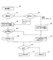
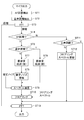
- FIG. 3 is a flowchart showing processing when a body CPU detects sound when moving image shooting is performed with the camera shown in FIG. 1.
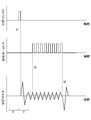
- FIG. It is the conceptual diagram which represented on the time axis the sound which generate
- FIG. 6 is a diagram showing a spectrum of a section C. It is a figure which shows an estimated noise spectrum. It is a figure which shows the spectrum which subtracted the noise from the spectrum of the area C.
- FIG. It is a figure which shows the spectrum after the flooring which uses the flooring spectrum A.
- FIG. It is a figure which shows the flooring spectrum A. It is a figure which shows the flooring spectrum B.
- FIG. It is a figure which shows the spectrum after the flooring which uses the flooring spectrum B.
- FIG. It is the schematic explaining the form of the 2nd process target sound used as the object of a noise reduction process. It is a figure which shows the spectrum of the background sound and noise of the area E.
- FIG. It is a figure which shows the estimation noise which uses the spectrum of the area E.
- FIG. It is a figure which shows the spectrum of the area F.
- FIG. It is a figure which shows the spectrum after performing a flooring process using the estimated noise of the area E.
- FIG. It is a figure which shows the estimation noise which uses the spectrum of the area F.
- FIG. It is a figure which shows the spectrum after performing a flooring process using the estimated noise of the area F.
- FIG. It is a figure which shows the spectrum after performing a flooring process using the estimated noise of the area F.
- FIG. 1 is an overall block diagram of a camera 3 according to the first embodiment of the present invention.
- the camera 3 has a camera body 5 and a lens barrel 7.
- the lens barrel 7 is detachably attached to the camera body 5.
- the camera according to this embodiment is not limited to the interchangeable lens camera as shown in FIG. 1, and the lens barrel 7 and the camera body 5 may be an integrated camera, and the type of camera is not particularly limited. .
- a plurality of optical components are arranged along the optical axis Z.
- An image sensor unit 15 is disposed in the camera body 5, and the front side of the image sensor unit 15 in the optical axis Z direction (the subject side along the Z axis is “the front side of the Z axis” or “the positive direction of the Z axis”).
- the shutter 33 is disposed on the “side”.
- a mirror 70 is disposed on the front side of the shutter 33 in the optical axis Z direction, and an optical lens group 24 built in the lens barrel 7 is disposed on the front side thereof.
- the camera body 5 includes a body CPU 50 and is connected to the lens CPU 80 via the lens contact 34.
- the body CPU 50 has a communication function with the lens barrel 7 and a control function of the camera body 5.
- the body CPU 50 includes a face recognition processing unit 51, a VAD processing unit 52, a noise detection unit 53, a noise reduction processing unit 54, and a noise reduction performance changing unit 55.
- the lens contact 34 electrically connects the body CPU 50 and the lens CPU 80.
- the body CPU 50 is connected to a power supply 47 for supplying power to the electronic components provided in the camera body 5 and the lens barrel 7.
- the body CPU 50 includes a moving image switch 41, a release switch 42, a microphone 43, a shooting mode changeover switch 44, a display unit 45, an EEPROM (nonvolatile memory) 46, a power supply 47, a recording medium 48, an image processing controller 31, an AF sensor 30, A voltage signal output circuit 28 and the like are connected.
- the image sensor 16 of the image sensor unit 15 is connected to the image processing controller 31 via the interface circuit 32.
- the image processing controller 31 and the interface circuit 32 control image processing of an image captured by the image sensor 16 based on a signal from the body CPU 50.
- the image sensor 16 is a solid-state image sensor such as a CCD or CMOS.
- the image sensor 16 photoelectrically converts the light beam that has passed through the optical lens group 24 to generate an image signal.
- the body CPU 50 acquires moving image data from the image sensor 16.
- the face recognition processing unit 51 detects the presence of the face of a specific subject (human or animal) using this moving image data.
- the shooting mode switch 44 is arranged on the camera body 5 so that the photographer can select one appropriate shooting mode (scene mode, auto mode, P / S / A / M mode, etc.) according to the shooting scene.
- scene mode for example, portrait, child snap, pet, landscape, close-up, etc. are prepared in advance.
- EEPROM 46 shooting parameters suitable for each scene mode are recorded.
- the body CPU 50 acquires necessary shooting parameters from the EEPROM 46 in accordance with each scene mode selected by the photographer.
- the microphone 43 converts sound generated during moving image capturing into a sound signal.
- the display unit 45 is mainly composed of a liquid crystal display device or the like, and displays output results and menus.
- the release switch 42 is a switch for operating the timing of still image shooting.
- the release switch 42 outputs a half-press signal and a full-press signal to the body CPU 50.
- the body CPU 50 controls shooting preparation operations such as AF control and AE control.
- the full-press signal is input from the release switch 42, the body CPU 50 performs mirror up, shutter drive, and the like. Controlling the exposure operation.
- the quick return mirror 70 is for projecting an image on the viewfinder when determining the composition, and retracts from the optical path during exposure.
- the quick return mirror 70 is driven by a mirror driving unit (not shown) (for example, a DC motor).
- the sub mirror 70 a that guides light to the AF sensor 30 is connected to the quick return mirror 70.
- the sub mirror 70a is also retracted from the optical path during exposure.
- the shutter 33 controls the exposure time.
- the shutter 33 is driven by a shutter driving unit (not shown) (for example, a DC motor) based on control from the body CPU 50.
- a shutter driving unit for example, a DC motor
- the AF sensor 30 is a sensor for performing autofocus (AF).
- AF autofocus
- a CCD is usually used.
- the moving image switch 41 outputs a moving image shooting start / end signal to the body CPU 50.
- the body CPU 50 obtains a moving image shooting start signal from the moving image switch 41
- the body CPU 50 issues a mirror up and shutter opening operation command.
- the light beam that has passed through the optical lens group 24 is guided to the image sensor 16, and moving image shooting (live view shooting) is started.
- the body CPU 50 obtains the moving image shooting end signal from the moving image switch 41
- the body CPU 50 issues a mirror down and shutter closing operation command, and the moving image shooting ends. Autofocus during live view shooting is performed by the body CPU 50 based on moving image data output from the image sensor 16 (contrast AF).
- the lens barrel 7 shown in FIG. 1 includes an optical lens group including an autofocus (AF) lens 24, a focal length encoder 74, a distance encoder 72, a drive motor 76 for driving the AF lens 24, a lens CPU 80, a lens contact 34, and the like. Is provided.
- AF autofocus
- the lens CPU 80 has a communication function with the body CPU 50 and a control function for electronic components mounted on the lens barrel 7. For example, the lens CPU 80 outputs focal distance information, subject distance information, and the like to the body CPU 50 via the lens contact 34.
- the lens CPU 80 receives AF information, moving image start / end information, release information, and the like from the body CPU 50.
- the lens CPU 80 can control the drive motor 76 and the like of the AF lens 24 based on these pieces of information.
- the focal length encoder 74 calculates the focal length from the position information of the zoom lens group (not shown) and outputs it to the lens CPU 80.
- the distance encoder 72 calculates the subject distance from the position information of the focusing lens group including the AF lens 24 and outputs it to the lens CPU 80.
- the subject distance information is used for dimming a flash (not shown).
- the camera body 5 is provided with a voltage signal output circuit 28.
- the voltage signal output circuit 28 outputs a voltage to a plurality of electrodes provided in the dust filter 18 in the image sensor unit 15 based on a control signal from the body CPU 50.
- the face recognition processing unit 51 of the body CPU 50 detects whether or not a face of a specific subject exists in the moving image data based on the moving image data created by the image sensor 16. For detecting whether or not a face of a specific subject exists in the moving image data, a known face recognition function such as template matching can be used.
- the body CPU 50 acquires image data from the image sensor 16 for each frame (for example, 1 msec), and generates continuous moving image data.
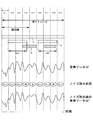
- the sound B generated between the frames 61 to 69 is conceptually described on behalf of only the continuous image frames 61 to 69.
- the sound B may include a voice H and noise N uttered by a specific subject.
- the microphone 43 shown in FIG. 1 picks up such a sound B and outputs it to the body CPU 50 as audio data M conceptually shown in FIG.
- the VAD processing unit (speech detection unit) 52 illustrated in FIG. 1 extracts power information from the speech data M, and is larger than the first lower limit threshold as conceptually illustrated in FIG. 4 from the extracted frequency information. From the start to the end of the frequency band, it is detected as a voice section in which voice of humans or animals is generated.
- the lens CPU 80 shown in FIG. 1 drives the AF lens 24 by outputting an AF drive signal to the AF drive motor 76.
- the noise detection unit 53 of the body CPU 50 is connected to the lens CPU 80 via the lens contact 34, and can directly detect the AF drive signal.
- the noise reduction processing unit 54 performs noise reduction processing described below.
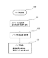
- step S30 when the noise reduction processing unit 54 reads the noise reduction start signal, in step S31, the noise reduction processing unit 54 reads, for example, the waveform of the antiphase of the AF noise stored in the EEPROM 46 in advance.
- step S32 the waveform of the anti-phase of the AF noise is multiplied by a noise reduction coefficient (a normal level reduction coefficient or a low level reduction coefficient described later).
- step S33 noise reduction is performed by adding the waveform obtained as a result of multiplication in step S32 to the audio
- the noise reduction performance changing unit 55 sets a small noise reduction coefficient by the noise reduction processing unit 54 described above when the face recognition processing unit 51 detects the presence of a face of a specific subject. That is, the noise reduction coefficient by the noise reduction processing unit 54 is set to a low level reduction coefficient. Alternatively, when the noise reduction performance changing unit 55 acquires a portrait, child snap, or pet scene mode signal by the shooting mode changeover switch 44, the noise reduction coefficient by the noise reduction processing unit 54 is changed to a low level reduction coefficient. Set.
- step S02 the body CPU 50 specifies the moving image data at the start of audio data M corresponding to a certain moving image frame. It is determined whether or not the subject's face exists. That is, when the body CPU 50 determines that the face of the specific subject exists in the moving image data, the process proceeds to step S03.
- step S03 the lower limit threshold of the frequency to be detected by the VAD processing unit 52 as the boundary of the audio section is lowered and set to the second lower limit threshold t2, and in step S04, the body CPU 50 sets each frame constituting the moving image. It is determined whether or not the voice data M is in the voice section (voice section VAD shown in FIG. 3) at the timing of the boundary between the corresponding frames.
- the process proceeds to step S05.
- step S05 the body CPU 50 reduces the noise reduction coefficient by the noise reduction performance changing unit 55 (low level reduction coefficient). If the body CPU 50 determines in step S04 that the voice data M is outside the voice section, the process proceeds to step S08 (described later).
- step S09 the body CPU 50 determines whether or not noise is detected.
- the process proceeds to step S10.
- the low level reduction coefficient described above is shown in FIG. Noise reduction processing is performed on the audio data M.
- step S09 if the body CPU 50 does not detect noise at the start of the audio data M corresponding to a certain moving image frame, the process proceeds to step S11, and noise reduction processing is not performed on the moving image frame.
- step S06 the body CPU 50 detects an input signal from the photographing mode changeover switch 44, and determines whether the photographing mode is portrait, child snap, or pet. If the body CPU 50 determines that the photographing mode is one of portrait, child snap, and pet, the process proceeds to step S03.
- step S06 if the body CPU 50 determines that it is a landscape or close-up shooting mode, the process proceeds to step S07, and the body CPU 50 sets the lower limit threshold value of the frequency to be used as a voice section boundary in the VAD processing unit 52.
- the first lower limit threshold t1 is set.
- step S07 the body CPU 50 does not have to detect the voice section VAD.
- step S08 the body CPU 50 sets the noise reduction coefficient by the noise reduction performance changing unit 55 to a normal state (normal level reduction coefficient).
- step S09 the body CPU 50 determines whether or not noise is detected. If the body CPU 50 detects noise at the start of the audio data M corresponding to a certain moving image frame, the process proceeds to step S10. In the moving image frame, the normal level reduction coefficient described above is used, as shown in FIG. Noise reduction processing is performed on the audio data M. In step S09, if the body CPU 50 does not detect noise at the start of the audio data M corresponding to a certain moving image frame, the process proceeds to step S11, and noise reduction processing is not performed on the moving image frame.
- step S03 by setting the lower limit threshold value of the frequency to be the boundary of the voice section to the second lower limit threshold value t2, it is possible to reliably pick up human or animal sounds.
- the body CPU 50 performs the above-described operation on the audio data M corresponding to the frame (noise reduction with a low level reduction coefficient or normal level reduction). Either noise reduction is performed using a coefficient or noise reduction is not performed). That is, when noise reduction is performed with a low level reduction coefficient, it is indicated by “weak” in FIG. 3, when noise reduction is performed with a normal level reduction coefficient, it is indicated by “medium”, and noise reduction is not performed.
- the body CPU 50 generates the audio data M ′ after noise reduction shown in FIG. 3 (the audio data M ′ is conceptually shown). Shown).
- the noise is reduced because the body CPU 50 does not detect the sound of a specific subject and does not detect noise at the start of the frame 61. No processing is performed.
- the body CPU 50 detects the audio of the specific subject at the start of the frames 62 and 63, but no noise is detected, so no noise reduction processing is performed.
- the body CPU 50 detects the sound of the specific subject at the start of the frame 64, and also detects noise. Prevents audio from deteriorating.
- the body CPU 50 does not detect the audio of the specific subject at the start of the frame 65, but detects the noise. Perform reduction processing.
- the body CPU 50 has not detected the audio of a specific subject and has not detected noise, so no noise reduction processing is performed.
- the body CPU 50 detects the audio of the specific subject at the start of the frame 67, but no noise is detected, so no noise reduction processing is performed.
- the body CPU 50 detects the sound of the specific subject at the start of the frame 68 and also detects noise. Prevents audio from deteriorating.
- the body CPU 50 has not detected the audio of a specific subject and has not detected noise, so no noise reduction processing is performed.
- the image sensor 16 captures a moving image
- the microphone 43 converts the sound B generated during the capturing of the moving image into a sound signal M.
- This sound B may contain noise N.
- the noise detection unit 53 detects whether or not the noise N is generated.
- the noise reduction processing unit 54 reduces the noise signal corresponding to the noise N from the sound signal M. .
- the VAD processing unit 52 detects a non-noise signal.
- Non-noise signals are all audio signals corresponding to at least the frequency range of human voice, such as human or animal voice or music.
- the sound signal including the non-noise signal is processed as a voice section, and the data not including the non-noise signal is processed as a non-voice section.
- the VAD processing unit 52 uses the above-described known VAD. Further, the body CPU 50 predicts a specific subject from the output signal of the shooting mode changeover switch 44, or the body CPU 50 (face recognition processing unit 51) recognizes the specific subject.
- the body CPU 50 determines that the scene is one of portrait, child snap, and pet (step S06), it can be predicted that a specific subject emits the sound H.
- the body CPU 50 can recognize the presence of the specific subject by detecting the presence of the face of the specific subject in the moving image data (step S02).
- the noise reduction performance changing unit 55 reduces the noise signal reduction performance of the noise reduction processing unit 54. That is, the noise reduction performance changing unit 55 performs the noise signal reduction performance by the noise reduction processing unit 54 in the case where the noise signal is detected in the voice section, compared to the case where the noise signal is detected in the non-voice section. Make it smaller. For this reason, it is possible to minimize the deterioration of the non-noise signal recorded in the voice section. For this reason, human and animal sounds can be clearly recorded, and the viewing quality of moving images is improved.
- the program according to the present embodiment causes the computer to execute the above-described unit for moving image data captured in advance.
- a program for causing a computer to execute the above-described unit is recorded on moving image data captured in advance. For this reason, when moving image data captured in advance is later edited on a computer, it is possible to minimize deterioration of a non-noise signal in a voice section.
- the program and recording medium of the present embodiment can minimize degradation of a non-noise signal in a voice section, Animal voices can be clearly recorded.
- the noise signal reduction effect is proportional to the noise reduction coefficient. Since the body CPU 50 varies the noise reduction coefficient between the normal level reduction coefficient and the low level reduction coefficient depending on whether or not a specific subject is predicted or recognized, the noise can be reduced without complicated calculation processing. The magnitude of the signal reduction effect can be changed.
- the noise signal reduction effect can be reduced (low level reduction coefficient), deterioration of the non-noise signal in the voice section can be minimized, and human or Animal voices can be clearly recorded.
- the noise signal reduction effect can be increased (normal level reduction coefficient) compared to the case of the low level reduction coefficient, and in the non-speech section. Therefore, it is possible to suitably reduce the noise signal.
- the face recognition processing unit 51 can effectively recognize the presence of the face of the subject by using a known face recognition function. While the face recognition processing unit 51 recognizes the presence of the subject's face, there is a high possibility that the subject will sound. Therefore, the noise reduction performance changing unit 55 reduces the noise signal reduction performance, thereby reducing the voice. The degradation of non-noise signals in the section can be minimized, and human and animal voices can be clearly recorded.
- the body CPU 50 predicts that a specific subject emits the sound H, and the noise reduction performance changing unit 55 reduces the noise signal reduction performance. By doing so, it is possible to minimize the deterioration of the non-noise signal in the voice section and to clearly record the voices of humans and animals.
- the subject determination unit 50 causes the photographer to pronounce a specific subject. Predict that it is not intended. Therefore, in these scene modes, the noise reduction performance changing unit 55 sets the noise signal reduction performance to the normal state. Therefore, the detected noise signal can be effectively reduced.
- the noise detection unit 53 may detect the noise N by detecting at least an autofocus drive signal.
- the noise detection unit 53 may detect the noise N by detecting at least one of autofocus, camera shake correction, and zooming drive signals.
- the noise generation source and the noise detection unit 53 may be directly connected. During driving such as autofocus, camera shake correction, and zooming, the noise detector 53 may detect these drive signals. In this case, the noise N accompanying the driving can be reliably detected.
- the VAD processing unit (sound detection unit) 52 detects the sound signal from the sound signal M within the range from the lower limit threshold to the upper limit threshold of the frequency of the sound signal M.
- the body CPU 50 face recognition processing unit 51
- the body CPU 50 face recognition processing unit 51
- the body CPU 50 determines that it is a portrait, child snap, or pet shooting scene
- the audio signal The VAD processing unit 52 may lower the lower limit threshold and set the first lower limit threshold to the second lower limit threshold so as to widen the detection range.
- the body CPU 50 face recognition processing unit 51
- the VAD processing unit 52 may set the lower limit threshold to the first lower limit threshold.
- the subject determination units 50 and 51 are predicting or recognizing a specific subject (human or animal) by applying known VAD, the audio signal of the human or animal is increased by widening the detection range of the audio signal. Can be detected more clearly.
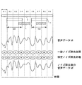
- the sound B shown in FIG. 6 is considered to contain general noise.
- the body CPU 50 does not detect the audio of a specific subject at the start of the frame 61, but detects general noise. Perform noise reduction processing.
- the body CPU 50 detects the sound of the specific subject at the start of the frame 64, and also detects the specific noise. To prevent the sound of a specific subject from deteriorating.
- the body CPU 50 does not detect the sound of a specific subject and detects general noise. Furthermore, the body CPU 50 also detects specific noise. In this case, the specific noise is reduced by the normal level reduction coefficient.
- the description is given using the camera having the mirror mechanism, but the present invention can also be applied to a system camera that does not include the mirror mechanism.
- the noise target detected by the above-described noise detection unit is not particularly limited, and the noise detection unit includes a camera shake correction lens driving motor sound, a vehicle passing sound (noise), a camera operation button operation sound, and the like. Can be detected.
- the noise reduction program and the voice detection unit are not limited to the above-described embodiments, and a general noise detection program and a general voice detection program can be used.
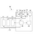
- FIG. 7 is a block diagram showing the configuration of the camera of the third embodiment.
- the camera 100 captures a lens barrel 110 and a subject image that has passed through the lens barrel 110, performs A / D conversion, and performs image processing to generate image data.
- a / D conversion is performed on the collected sound information, and a noise information processing unit 130 that performs noise reduction processing, image data obtained by the image processing unit 120, and an audio signal obtained by the sound information processing unit 130
- a recording unit 140 for recording and a CPU 150 are provided.
- the lens barrel 110 includes a focus adjustment lens (hereinafter referred to as an AF (Auto Focus) lens, a camera shake correction lens (hereinafter referred to as a VR (Vibration Reduction) lens), a zoom lens, a zoom lens driving unit, a zoom encoder, an image blur correction unit, and the like.
- AF Auto Focus
- VR Camera shake correction lens
- a VR unit 111, an AF encoder 112, and an AF drive motor 113 are provided.
- the AF encoder 112 detects the position of the AF lens of the optical system and outputs it to the CPU 150.
- a driving control signal for controlling the position of the AF lens is input from the CPU 150 to the AF driving motor 113, and the position of the AF lens is controlled in accordance with the driving control signal.
- the CPU 150 controls the lens barrel 110 according to the set imaging conditions (for example, aperture value, exposure value, etc.).
- the CPU 150 generates a drive control signal for driving the zoom lens driving unit and the AF driving motor 113 and outputs the drive control signal to the zoom lens driving unit and the AF driving motor 113.
- the sound information processing unit 130 includes a microphone 131 that is a sound collection device, a sound signal processing unit 132 that processes sound information that has been collected and A / D converted, and a noise reduction processing unit 133.
- the sound signal processing unit 132 includes a voice section detection unit 134 that detects a voice section from sound information collected by the microphone 131, and a noise timing detection unit that detects timing at which operation noise occurs from the operation information of the AF driving motor 113. 135.
- the speech section detection unit 134 determines a section (speech section) including a speech signal and other sections (non-speech section) from the sound information collected by the microphone 131. Determine.
- the outline of the voice zone detection by the voice zone detector 134 will be described as follows.
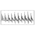
- FIG. 8 shows a speech waveform.
- the waveform shown in FIG. 9 is obtained.
- This voice waveform has the property (harmonic nature) that peaks concentrate on the fundamental frequency corresponding to the frequency of the voice, that is, the vocal cords, and the frequency band corresponding to its harmonics. Thus, it is possible to distinguish between speech and non-speech based on the magnitude of the peak value of the autocorrelation function.
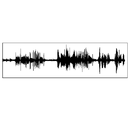
- FIG. 10A and FIG. 10B show an example in which a speech section is detected using an autocorrelation function.
- FIG. 10A shows an output waveform from the microphone 131, in which AF noise occurs in the first half, and sound and AF noise occur in the second half.
- a threshold is set at the peak of the autocorrelation function, and a portion equal to or higher than the threshold is shown as High, a waveform as shown in FIG. 10B is obtained.
- a threshold is set at the peak of the autocorrelation function, and a portion equal to or higher than the threshold is shown as High
- FIG. 10B is obtained.
- the noise timing detection unit 135 detects the timing at which operation noise occurs from the operation information of the AF drive motor 113.
- the generation timing of the operation noise by the noise timing detector 135 is detected (estimated) using an AF drive command that instructs the CPU 150 to output a drive control signal for the AF drive motor 113 and an output from the AF encoder 112. .
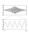
- operation noise generation timing detection by the noise timing detection unit 135 will be described as follows. As shown in FIG. 11, when the AF drive motor 113 is operated by the output of the AF drive command, the operation continues from the operation start time t1 of the AF drive motor 113, which is the output time of the AF drive command, to the operation end time t3. Operation noise is generated.
- the microphone 131 collects sound information in which operation noise is superimposed on the recording target sound such as the sound of the subject, and the collected sound information is output from the microphone 131.
- the AF encoder 112 may output from a time t2 that is later than the operation start time t1 of the AF driving motor 113 due to the influence of backlash or the like that occurs in the gear train of the AF driving system. Therefore, the noise timing detection unit 135 detects from the output time t1 of the AF drive command to the output stop t3 of the AF encoder 112 as operation noise generation timing, and detects the other as non-noise timing.
- the signal actually output from the microphone 131 during the AF operation is a signal in which the operation noise is superimposed on the target sound, but only the operation noise is shown in FIG. 11 for simplicity of explanation.
- the noise reduction processing unit 133 reduces the impact noise generated at the start of the AF operation and at the end of the AF operation among the operation noises shown in FIG.
- the noise reduction processing unit 133 obtains the first frequency spectrum of the window X before the generation of the operational noise and the second frequency spectrum of the window Y after the generation of the operational noise shown in FIG.
- the obtained first frequency spectrum is compared with the second frequency spectrum, and if the second frequency spectrum is larger than the first frequency spectrum as a result of the comparison, the second frequency spectrum is replaced with the first frequency spectrum, thereby Perform noise reduction processing.
- the spectrum up to a predetermined frequency (for example, 4000 Hz) is stored without replacement, and when it is detected that it is a non-speech section, The spectrum up to a predetermined frequency (for example, 500 Hz) smaller than that is stored without being replaced. That is, the upper limit of the frequency to be saved when it is detected as a voice segment is, for example, 4000 Hz, and the upper limit of the frequency to be saved when it is detected as a non-speech segment is, for example, 500 Hz. Is detected, a first impact noise reduction process that is weaker than that detected when the non-speech section is detected is performed.
- a predetermined frequency for example, 4000 Hz
- the noise reduction processing unit 133 estimates noise from the frequency spectrum when the voice segment detection unit 134 detects that it is a non-speech segment and performs strong impact noise reduction processing, and updates the estimated noise. Then, using the estimated noise, a spectrum subtraction process (second noise reduction process) for generating a frequency spectrum by subtracting from the frequency spectrum on which the first impact sound noise reduction process has been performed is performed.
- the sound information processing unit 130 divides the sound information output from the microphone 131 into predetermined intervals and weights them with a window function, and Fourier-transforms the sound data for each interval.
- FFT Fast Fourier Transform
- IFFT IFFT
- IFFT inverse Fourier transform
- It has a processing unit for converting the spectrum (sound information) after the noise reduction processing into the time domain by performing Inverse Fast Fourier Transform. The illustration of these processing units is omitted.
- the noise reduction processing unit 133 has a flooring function for correcting the spectrum when the spectrum is significantly reduced or the spectrum disappears by the second noise reduction processing (spectrum subtraction processing).
- This flooring is a flooring spectrum generated based on sound information when the noise timing detection unit 135 detects non-noise timing and the voice interval detection unit 134 detects non-sound timing.
- the spectrum after subtraction in the second noise reduction processing and if the spectrum after subtraction is lower than the flooring spectrum (spectrum intensity is small), the sound information (spectrum) adopting the flooring spectrum And IFFT process this. However, if the spectrum after subtraction exceeds the flooring spectrum (the spectrum intensity is high), the flooring process may or may not be performed.
- the flooring spectrum used for the flooring function uses sound information when the noise timing detection unit 135 detects non-noise timing and the voice segment detection unit 134 detects non-speech segment. Update.
- the flooring spectrum does not include either the operating noise spectrum or the voice spectrum, but only the background sound is included.
- the voice spectrum is added during the flooring process, and is not originally present in the sound information after the noise reduction process. The sound is not generated.
- FIG. 12 is a flowchart showing the flow of the noise reduction processing operation.
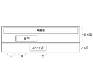
- FIG. 13 is a schematic diagram illustrating the form of the first processing target sound that is the target of the noise reduction processing.
- the first processing target sound is a form in which section A generates only background sound, section B generates background sound and sound (target sound), and section C generates background sound and AF noise. .
- An operation of reducing AF noise from the sound information collected and output by the microphone 131 in the section C of the first processing target sound shown in FIG. 13 and flooring update will be described.
- Step ST1 the noise timing detection unit 135 starts detection of noise timing based on sound information output from the microphone 131.
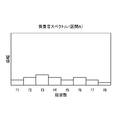
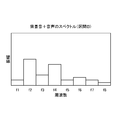
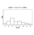
- the sound information (spectrum) collected by the microphone 43 at this time is shown in FIG.
- Step ST2 the voice segment detection unit 134 starts detection of the voice segment based on the sound information output from the microphone 131.
- Step ST3 Sound information output from the microphone 131 is subjected to FFT processing, and is divided into frequency domain amplitude information and phase information.
- Step ST4 the noise timing detection unit 135 detects (determines) whether it is the generation timing of the operation noise or the non-noise timing (that is, whether or not it is the AF section).
- Step ST4 In step ST4, it is determined that section C is the timing of occurrence of operation noise (AF section, YES), and the process proceeds to step ST5. (Step ST4, NO) The sections A and B are determined to be non-noise timing, and the process proceeds to step ST11.
- Step ST5 the speech segment detection unit 134 detects (determines) whether it is a speech segment or a non-speech segment. Since section C is a non-voice section (NO), the process proceeds to step ST7.
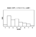
- Step ST7 the AF operation start time and AF operation end time are included, a strong impact noise reduction process is performed in which the upper limit is stored without replacing the spectrum up to a predetermined frequency (for example, 500 Hz). The spectrum of FIG. 16 is obtained.
- a predetermined frequency for example, 500 Hz
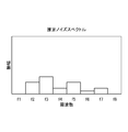
- Step ST8 Next, the noise in the spectrum (FIG. 16) obtained by the noise reduction process in step ST7 is estimated, and an estimated noise spectrum as shown in FIG. 17 is output to step ST9.
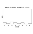
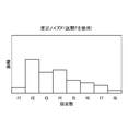
- Step ST9 Subsequently, a spectrum subtraction process (second noise reduction process) for subtracting the estimated noise spectrum (FIG. 17) obtained by the estimation of step ST8 from the spectrum (FIG. 16) obtained by the shock noise reduction process of step ST7. And a spectrum as shown in FIG. 18 is obtained.
- second noise reduction process for subtracting the estimated noise spectrum (FIG. 17) obtained by the estimation of step ST8 from the spectrum (FIG. 16) obtained by the shock noise reduction process of step ST7.
- a spectrum as shown in FIG. 18 is obtained.
- the second noise reduction process may cause the spectrum of FIG. 18 to be significantly reduced or lost, and therefore, flooring for correcting the spectrum of FIG. 18 is performed to cope with this. .
- the magnitudes of the spectrum of FIG. 18 and the reference flooring spectrum are compared.
- a spectrum having a high intensity is adopted to generate a spectrum shown in FIG.
- the flooring spectrum used here is mentioned later, it is a flooring spectrum calculated
- Step ST11 the voice section detection unit 134 detects (determines) whether it is a voice section or a non-speech section (section of only background sound). As a result, it is determined that the section B is a voice section (YES), and noise reduction processing, spectrum subtraction, and flooring are not performed, and the process proceeds to step ST13.
- the section A is determined to be a non-voice section (NO), and the process proceeds to step ST12.
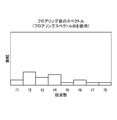
- Step ST12 the amplitude at each frequency of the spectrum of the section A in which only the background sound shown in FIG. 14 is generated is halved to obtain a flooring spectrum as shown in FIG.
- This flooring spectrum (FIG. 20) is used for flooring in step ST10 as described above, and is updated to this flooring spectrum. If flooring is performed using the flooring spectrum of FIG. 21 obtained by halving the amplitude at each frequency of the spectrum shown in FIG. 15 in section B, the spectrum is as shown in FIG. If the spectrum of FIG. 22 is the spectrum of the section C, the components (particularly f2, f4) of the speech spectrum included in the section B (FIG. 15) are also included, and an accurate target sound cannot be obtained.
- the flooring spectrum (FIG. 20) used for flooring does not include the spectrum of voice and operation noise. For this reason, in flooring of step ST10, it is possible to prevent AF noise and voice spectrums from being added, and undesired operation noise and voice from being generated in the sound information after the noise reduction processing.
- Step ST13 In the final step ST13, IFFT processing is performed using the phase divided in step ST3, thereby converting the spectrum after the noise reduction processing into the time domain and outputting it to the recording unit 140.
- FIG. 23 is a schematic diagram illustrating the form of the second processing target sound that is the target of the noise reduction processing.
- the processing target sound has a form in which section D generates only background sound, section E generates background sound and AF noise, and section F generates background sound, sound, and AF noise.
- section D generates only background sound
- section E generates background sound and AF noise
- section F generates background sound, sound, and AF noise.
- Steps ST1 to ST4 are the same as the above-described section C of the first processing target sound, and are therefore omitted.
- Step ST5 In step ST5, it is determined that the section F is a voice section (YES), and the process proceeds to step ST6.
- Step ST6 In step ST6, when the AF operation start time and AF operation end time are included, a weak first impact noise reduction process is performed in which the upper limit is stored without replacing the spectrum up to a predetermined frequency (for example, 4000 Hz). It is. When the AF operation start time and AF operation end time are not included, it is determined that the impact noise is not included, and the impact noise reduction process is not performed.
- a predetermined frequency for example, 4000 Hz
- the spectrum subjected to the first impact sound noise reduction processing includes speech vector components f2 and f4. This spectrum is not used for updating the estimated noise, and the process proceeds to step ST9 for performing the spectrum subtraction process which is the second noise reduction process.
- a spectrum as shown in FIG. 24 is obtained in the section E which is the generation timing of the operating noise and is a non-voice section, and in the section F, a spectrum as shown in FIG. can get.
- step ST8 noise is estimated from the spectrum obtained in section E and updated.
- the updated estimated noise has a spectrum as shown in FIG.
- step ST9 the estimated noise spectrum (FIG. 25) is subtracted from the spectrum in section F (FIG. 26), and further, flooring is performed in step ST10, thereby generating a spectrum as shown in FIG.
- the flooring spectrum in the case of the second processing target sound is obtained from the section D in which only the background sound is generated.
- the spectrum of FIG. 20 obtained by halving FIG. 14 as in the case of the first processing target sound is used.
- the voice spectrum can exist as shown in FIG.
- this embodiment has the following effects.
- Second noise reduction processing spectrum subtraction processing in which noise is estimated from sound information when it is determined to be a non-speech section after the first noise reduction processing, and the estimated noise is subtracted.
- the noise is obtained from the sound information in the non-speech section, it is possible to obtain a processed sound very close to the target sound without deleting the sound itself.
- the generation timing of the operation noise is detected from the operation information of the drive unit in the camera 100, and the process proceeds to the noise reduction process when the noise generation timing is detected. Therefore, it is possible to appropriately and rationally perform noise reduction processing only when necessary without performing useless noise reduction processing.
- flooring is performed on the sound information after the second noise reduction process (spectrum subtraction process), it is possible to correct a spectrum that may be reduced or disappear due to spectrum subtraction. As a result, it is possible to prevent the noise from being excessively reduced and to secure (record) a sound close to the target sound among the collected sound information.
- the present invention is not limited to the above-described embodiment, and various modifications and changes as described below are possible, and these are also within the scope of the present invention.
- the configuration has been described in which noise information collected by the microphone 131 is subjected to noise reduction processing in real time.
- the present invention is not limited to this, and the sound information collected by the microphone 131 is temporarily stored in a buffer memory or the like, and the sound information is read from the buffer memory or the like as necessary to perform noise reduction processing. May be. In this case, it is possible to reduce the load on the apparatus when processing in real time.
- transformation form can also be used in combination suitably, detailed description is abbreviate
Landscapes
- Engineering & Computer Science (AREA)
- Signal Processing (AREA)
- Multimedia (AREA)
- Computational Linguistics (AREA)
- Health & Medical Sciences (AREA)
- Audiology, Speech & Language Pathology (AREA)
- Human Computer Interaction (AREA)
- Physics & Mathematics (AREA)
- Acoustics & Sound (AREA)
- Quality & Reliability (AREA)
- Studio Devices (AREA)
Abstract
音声等の目的音の劣化を招くことなく、ノイズを適切に低減することができる撮像装置、プログラム、記録媒体およびノイズ低減方法を提供する。 本発明の撮像装置は、動画の撮像を行う動画撮像部16と、動画の撮像中に発生する音Bを音信号Mに変換する信号変換部43と、特定の被写体を予測または認識する被写体判断部50,51と、動画の撮像中に発生する音に含まれるノイズNを検出するノイズ検出部53と、音信号Mから、ノイズ信号を低減するノイズ低減部54と、音信号Mから、非ノイズ信号を検出する音声検出部52と、被写体判断部50,51が、特定の被写体を予測または認識している場合に、ノイズ低減部54によるノイズ信号の低減性能を小さくするノイズ低減性能変更部55とを有する。
Description
本発明は、撮像装置、プログラム、記録媒体、およびノイズ低減方法に関する。
近年、動画撮影機能を搭載した撮像装置が普及してきている。一般に、動画の撮像中に発生する音には、ノイズが含まれることがある。たとえば、オートフォーカスレンズの駆動音等は、ノイズに該当する。特に、動画撮影を前提として設計されていないレンズ鏡筒では、このような駆動音が大きく、ノイズも増大してしまう。そこで、ノイズ低減処理を行うことがある。
たとえば、マイクが拾った音信号に含まれる人物音声を強調して抽出し、人物音声を含む音信号(音声区間)と、人物音声を含まない音信号(非音声区間)とを区別する技術(VAD:Voice Activity Detection)がある(特許文献1参照)。VADを利用して、非音声区間の音信号を用い推定ノイズを算出し、推定ノイズを音信号から差し引くことで、ノイズを抑制することができる(例えば、特許文献1参照)。
また、動画撮影が可能な撮像装置において動画撮影時には、オートフォーカスレンズの駆動部の動作に伴い発生する動作音(以下、AFノイズという)等のノイズが、マイク等の集音装置により集音され、被写体の発する音声等の目的音に混入し、目的音の品質を損なうことがある。
このようなAFノイズを低減する方法として、AF駆動部の動作前に入力される音声信号のパワー値を取得し、この音声信号のパワー値に基づいてフロアリング係数を制御(変化)させることにより、ノイズを低減する方法が提案されている(例えば、特許文献2参照)。
このようなAFノイズを低減する方法として、AF駆動部の動作前に入力される音声信号のパワー値を取得し、この音声信号のパワー値に基づいてフロアリング係数を制御(変化)させることにより、ノイズを低減する方法が提案されている(例えば、特許文献2参照)。
しかし、特許文献1のように音声区間と非音声区間とで、音信号から推定ノイズを一律に差し引くと、音声区間において記録される人物やペット等の動物の音声が劣化する。
また、特許文献2によるノイズ低減処理の場合は、AFノイズを低減することができる反面、音声等の目的音を劣化する可能性が高い。
本発明の課題は、音声等の目的音の劣化を招くことなく、ノイズを適切に低減することができる撮像装置、プログラム、記録媒体およびノイズ低減方法を提供することである。
本発明は、以下のような解決手段により前記課題を解決する。
本発明の第1の見地によると、動画の撮像を行う動画撮像部と、前記動画の撮像中に発生する音を音信号に変換する信号変換部と、特定の被写体を予測または認識する被写体判断部と、前記動画の撮像中に発生する音に含まれるノイズを検出するノイズ検出部と、前記音信号から、ノイズ信号を低減するノイズ低減部と、前記音信号から、非ノイズ信号を検出する音声検出部と、前記被写体判断部が、特定の前記被写体を予測または認識している場合に、前記ノイズ低減部による前記ノイズ信号の低減性能を小さくするノイズ低減性能変更部とを有する撮像装置を提供する。
前記ノイズ低減部は、ノイズ低減係数に基づき、前記音信号から、前記ノイズ信号を低減し、前記被写体判断部が、特定の前記被写体を予測または認識している場合に、前記ノイズ低減性能変更部が、前記ノイズ信号の前記低減性能を小さくするように、前記ノイズ低減係数を、比較的小さな低レベル低減係数に設定してもよい。
前記被写体判断部が、特定の前記被写体を予測または認識していない場合に、前記ノイズ低減部が、前記ノイズ低減係数を、前記低レベル低減係数より大きな通常レベル低減係数に設定してもよい。
前記被写体判断部は、前記動画撮像部が撮像した映像信号に基づき、前記被写体の顔の存在を認識する顔認識部であってもよい。
前記被写体判断部は、予め準備された複数の撮影モードごとに、特定の前記被写体を予測するシーンモード部であってもよい。
前記ノイズ検出部は、少なくともオートフォーカスの駆動信号を検出することにより、前記ノイズを検出してもよい。
前記音声検出部は、前記音信号の周波数の下限閾値から上限閾値までの範囲内で、前記音信号から、非ノイズ信号を検出し、前記被写体判断部が、特定の前記被写体を予測または認識している場合に、前記非ノイズ信号の検出範囲を広くするように、前記音声検出部は前記下限閾値を下げて、第1下限閾値から第2下限閾値に設定してもよい。
前記被写体判断部が、特定の前記被写体を予測または認識していない場合に、前記音声検出部は前記下限閾値を前記第1下限閾値に設定してもよい。
本発明の第2の見地によると、特定の被写体を予測または認識する被写体判断部、動画の撮像中に発生する音に対応する音信号から、ノイズ信号を低減するノイズ低減部、前記音信号から、人間または動物の音声信号を検出する音声検出部、および前記被写体判断部が、特定の前記被写体を予測または認識している場合に、前記ノイズ低減部による前記ノイズ信号の低減性能を小さくするノイズ低減性能変更部としてコンピュータを機能させるためのプログラムを提供する。
本発明の第3の見地によると、特定の被写体を予測または認識する被写体判断部、動画の撮像中に発生する音に対応する音信号から、ノイズ信号を低減するノイズ低減部、前記音信号から、人間または動物の音声信号を検出する音声検出部、および前記被写体判断部が、特定の前記被写体を予測または認識している場合に、前記ノイズ低減部による前記ノイズ信号の低減性能を小さくするノイズ低減性能変更部としてコンピュータを機能させるためのプログラムを記録したコンピュータ読み取り可能な記録媒体を提供する。
本発明の第4の見地によると、動画の撮像を行う工程と、前記動画の撮像中に発生する音を音信号に変換する工程と、特定の被写体を予測または認識する工程と、前記動画の撮像中に発生する音に含まれるノイズを検出する工程と、前記音信号から、ノイズ信号を低減する工程と、前記音信号から、人間または動物の音声信号を検出する工程と、特定の前記被写体を予測または認識している場合に、前記ノイズ信号の低減性能を小さくする工程とを有するノイズ低減方法を提供する。
本発明の第5の見地によると、集音装置と、前記集音装置により集音された音情報から音声区間を検出する音声区間検出部と、前記音声区間検出部の検出結果に基づいて、異なるノイズ低減処理を行うノイズ低減処理部と、を備える撮像装置を提供する。
該撮像装置内の駆動部の動作情報から動作ノイズの発生タイミングを検出するノイズタイミング検出部を備え、前記ノイズ低減処理部は、前記ノイズタイミング検出部の検出結果に基づいて、異なるノイズ低減処理を行ってもよい。
前記ノイズ低減処理部は、前記音声区間検出部により音声区間と検出された場合、前記音声区間検出部において非音声区間であると検出された場合よりも弱い低い第1のノイズ低減処理を行ってもよい。
前記ノイズ低減処理部は、前記音声区間検出部において非音声区間であると判定された場合の音情報からノイズを推定し、該推定されたノイズを、推定ノイズ減算前音情報から減算する第2のノイズ低減処理を行ってもよい。
前記ノイズ低減処理部は、前記音声区間検出部において非音声区間であると判定された場合の音情報からフロアリングスペクトルを求め、該フロアリングスペクトルを用いてフロアリング処理前音情報に対してフロアリング処理してもよい。
前記音声区間検出部による音声区間の検出は、音声波形の一部を切り出して自己相関関数を求め、その求めた自己相関関数のピーク値を用いて検出してもよい。
本発明の第6の見地によると、集音された音情報から音声区間を検出し、音声区間の検出結果に基づいて、異なるノイズ低減処理を行う撮像装置のノイズ低減方法を提供する。
前記撮像装置内の駆動部の動作情報から動作ノイズの発生タイミングを検出し、動作ノイズの発生タイミングの検出結果に基づいて、異なるノイズ低減処理を行ってもよい。
音声区間と検出された場合、非音声区間であると検出された場合よりも弱い第1のノイズ低減処理を行ってもよい。
非音声区間であると判定された場合の音情報からノイズを推定し、該推定されたノイズを、推定ノイズ減算前音情報から減算する第2のノイズ低減処理を行ってもよい。
非音声区間であると判定された場合の音情報からフロアリングスペクトルを求め、該フロアリングスペクトルを用いてフロアリング処理前音情報に対してフロアリング処理してもよい。
音声区間の検出は、音声波形の一部を切り出して自己相関関数を求め、その求めた自己相関関数のピーク値を用いて検出してもよい。
本発明によれば、音声等の目的音の劣化を招くことなく、ノイズを適切に低減することができる撮像装置、プログラム、記録媒体およびノイズ低減方法を提供することができる。
[第1実施形態]
図1は、本発明の第1実施形態に係るカメラ3の全体ブロック図である。カメラ3は、カメラボディ5とレンズ鏡筒7を有している。レンズ鏡筒7は、カメラボディ5に対して着脱自在に装着される。本実施形態に係るカメラとしては、図1に示すようなレンズ交換式カメラに限定されず、レンズ鏡筒7とカメラボディ5とが一体のカメラであってもよく、カメラの種類は特に限定されない。
図1は、本発明の第1実施形態に係るカメラ3の全体ブロック図である。カメラ3は、カメラボディ5とレンズ鏡筒7を有している。レンズ鏡筒7は、カメラボディ5に対して着脱自在に装着される。本実施形態に係るカメラとしては、図1に示すようなレンズ交換式カメラに限定されず、レンズ鏡筒7とカメラボディ5とが一体のカメラであってもよく、カメラの種類は特に限定されない。
カメラボディ5およびレンズ鏡筒7の内部には、光軸Zに沿って、複数の光学部品が配置されている。カメラボディ5には撮像素子ユニット15が配置されており、撮像素子ユニット15の光軸Z方向の前方側(Z軸に沿って被写体側を「Z軸の前方側」または「Z軸の正方向側」と称する)には、シャッタ33が配置してある。シャッタ33の光軸Z方向の前方側には、ミラー70が配置してあり、その前方側には、レンズ鏡筒7に内蔵してある光学レンズ群24が配置してある。
カメラボディ5には、ボディCPU50が内蔵してあり、レンズ接点34を介してレンズCPU80に接続してある。ボディCPU50は、レンズ鏡筒7との通信機能と、カメラボディ5の制御機能を有している。ボディCPU50は、顔認識処理部51、VAD処理部52、ノイズ検出部53、ノイズ低減処理部54、ノイズ低減性能変更部55を有している。レンズ接点34は、ボディCPU50と、レンズCPU80とを電気的に接続する。ボディCPU50には、カメラボディ5およびレンズ鏡筒7に備えられた電子部品に電力を供給するための電源47が接続してある。
ボディCPU50には、動画スイッチ41、レリーズスイッチ42、マイク43、撮影モード切替スイッチ44、表示部45、EEPROM(不揮発性メモリ)46、電源47、記録媒体48、画像処理コントローラ31、AFセンサ30、電圧信号出力回路28などが接続してある。画像処理コントローラ31には、インターフェース回路32を介して、撮像素子ユニット15の撮像素子16が接続してある。画像処理コントローラ31およびインターフェース回路32は、ボディCPU50からの信号に基づき、撮像素子16によって撮像された画像の画像処理を制御する。撮像素子16は、たとえばCCDやCMOS等の固体撮像素子である。
撮像素子16は、光学レンズ群24を通過した光束を光電変換して画像信号を生成する。動画撮影時には、ボディCPU50が、この撮像素子16から、動画データを取得する。顔認識処理部51は、この動画データを用いて、特定の被写体(人間または動物)の顔の存在を検出する。
撮影モード切替スイッチ44は、撮影者が、撮影シーンに応じて適切な撮影モード(シーンモード、オートモード、P・S・A・Mモード等)を一つ選択できるように、カメラボディ5に配置されている。シーンモードとしては、たとえば、ポートレート、子供スナップ、ペット、風景、クローズアップ等が予め準備されている。EEPROM46には、それぞれのシーンモードに適した撮影パラメータ等が記録されている。ボディCPU50は、撮影者が選択したそれぞれのシーンモードに応じて、EEPROM46から必要な撮影パラメータを取得する。マイク43は、動画の撮像中に発生する音を、音信号に変換する。
表示部45は、主として液晶表示装置などで構成され、出力結果やメニューなどを表示する。レリーズスイッチ42は、静止画撮影のタイミングを操作するスイッチである。レリーズスイッチ42は、ボディCPU50に対して、半押し信号および全押し信号を出力する。ボディCPU50は、レリーズスイッチ42から半押し信号が入力されると、AF制御、AE制御等の撮影準備動作を制御し、レリーズスイッチ42から全押し信号が入力されると、ミラーアップ、シャッタ駆動等の露光動作を制御する。
クイックリターンミラー70は、構図決定の際にファインダーに像を映し出すためのもので、露光中は光路から退避する。クイックリターンミラー70は、不図示のミラー駆動部(例えばDCモータ)により駆動される。
クイックリターンミラー70には、AFセンサ30に光を導くサブミラー70aが連結してある。このサブミラー70aも、露光中は光路から退避する。
シャッタ33は、露光時間を制御する。シャッタ33は、ボディCPU50からの制御に基づき、不図示のシャッタ駆動部(例えばDCモータ)によって駆動される。
AFセンサ30は、オートフォーカス(AF)を行うためのセンサである。このAFセンサ30としては、通常CCDが用いられる。
図1に示す動画スイッチ41は、動画撮影のタイミングを操作するスイッチである。動画スイッチ41は、ボディCPU50に対して、動画撮影の開始/終了信号を出力する。ボディCPU50は、動画スイッチ41から動画撮影の開始信号を取得すると、ミラーアップおよびシャッタ開動作の命令を行う。これにより、光学レンズ群24を通過した光束が、撮像素子16に導かれ、動画撮影(ライブビュー撮影)が開始される。また、ボディCPU50は、動画スイッチ41から動画撮影の終了信号を取得すると、ミラーダウンおよびシャッタ閉動作の命令を行い、動画撮影が終了する。ライブビュー撮影中のオートフォーカスは、ボディCPU50が、撮像素子16から出力された動画データに基づいて行われる(コントラストAF)。
図1に示すレンズ鏡筒7には、オートフォーカス(AF)レンズ24を含む光学レンズ群、焦点距離エンコーダ74、距離エンコーダ72、AFレンズ24を駆動する駆動モータ76、レンズCPU80、レンズ接点34等が具備してある。
レンズCPU80は、ボディCPU50との通信機能と、レンズ鏡筒7に搭載された電子部品の制御機能とを有している。例えば、レンズCPU80は、焦点距離情報、被写体距離情報等を、レンズ接点34を介してボディCPU50に出力する。また、レンズCPU80には、ボディCPU50から、AF情報、動画開始/終了情報、レリーズ情報等が入力される。レンズCPU80は、これらの情報に基づき、AFレンズ24の駆動モータ76等を制御することができる。
焦点距離エンコーダ74は、不図示のズームレンズ群の位置情報から、焦点距離を算出し、レンズCPU80に出力する。距離エンコーダ72は、AFレンズ24を含むフォーカシングレンズ群の位置情報より被写体距離を算出し、レンズCPU80に出力する。被写体距離情報は、不図示のフラッシュの調光などに使用される。
図1に示すように、カメラボディ5には、電圧信号出力回路28が備えられている。電圧信号出力回路28は、ボディCPU50からの制御信号に基づき、撮像素子ユニット15における防塵フィルタ18に備えられる複数の電極に電圧を出力する。
ボディCPU50の顔認識処理部51は、撮像素子16が作成した動画データに基づき、特定の被写体の顔が動画データに存在しているか否かを検出している。特定の被写体の顔が動画データに存在しているか否かの検出には、例えばテンプレートマッチング等、公知の顔認識機能を用いることができる。
図3に示すように、動画撮影時に、常に音Bが発生している場合について説明する。なお、ボディCPU50は、画像データを、各フレーム(例えば1m秒)毎に、撮像素子16から取得し、連続する動画データを生成している。図3では、連続する画像フレーム61~69のみを代表して、フレーム61~69間で発生している音Bを概念的に説明している。
音Bには、特定の被写体が発する声H、およびノイズNが含まれることがある。図1に示すマイク43は、このような音Bを拾い、図3に概念で示す音声データMとしてボディCPU50に出力している。なお、図1に示すVAD処理部(音声検出部)52は、音声データMからパワー情報を抽出し、抽出された周波数情報から、図4に概念的に示すように、第1下限閾値より大きい周波数帯域の始端から終端までを、人や動物などの音声が発生している音声区間として検出する。
図1に示すレンズCPU80は、AF駆動信号をAF駆動モータ76に出力することにより、AFレンズ24を駆動させている。ボディCPU50のノイズ検出部53は、レンズ接点34を介して、レンズCPU80とつながっており、AF駆動信号を直接検出することができる。ノイズ検出部53がAF駆動信号を検出すると、ノイズ低減処理部54は、以下に述べるノイズの低減処理を行う。
ノイズ低減処理部54によるノイズ(本実施形態では、特定のAF駆動ノイズ)の低減は、図5に示すフローチャートに基づき行われる。ステップS30において、ノイズ低減処理部54がノイズ低減開始信号を読み込むと、ステップS31において、ノイズ低減処理部54は、たとえばEEPROM46に予め記憶してあるAFノイズの逆位相の波形を読み込む。次に、ステップS32に進み、AFノイズの逆位相の波形に、ノイズ低減係数(後述する通常レベル低減係数または低レベル低減係数)を乗算する。次に、ステップS33に進み、ステップS32にて乗算した結果得られた波形を、図3に示す音声データMに加算することにより、ノイズの低減が行われる。
ノイズ低減性能変更部55は、顔認識処理部51が特定の被写体の顔の存在を検出している場合に、上述したノイズ低減処理部54によるノイズ低減係数を小さく設定する。すなわち、ノイズ低減処理部54によるノイズ低減係数を、低レベル低減係数に設定する。または、ノイズ低減性能変更部55は、撮影モード切替スイッチ44によるポートレート、子供スナップ、ペットのいずれかのシーンモード信号を取得すると、ノイズ低減処理部54によるノイズ低減係数を、低レベル低減係数に設定する。
次に、図2に示すフローチャートに基づき、図1に示すボディCPU50の動作について説明を行う。図2に示すように、ステップS01において、ボディCPU50が動画の撮影開始信号を受けると、ステップS02において、ボディCPU50が、ある動画フレームに対応する音声データMの開始時において、動画データに特定の被写体の顔が存在しているか否かを判断する。すなわち、ボディCPU50が、動画データに特定の被写体の顔が存在していると判断した場合には、ステップS03に進む。
ステップS03において、VAD処理部52において検出する音声区間の境界とすべき周波数の下限閾値を下げて第2下限閾値t2に設定し、さらにステップS04において、ボディCPU50が、動画を構成する各フレームに対応するフレームとフレームとの境界のタイミングで、音声データMが音声区間(図3に示す音声区間VAD)にあるか否かを判断する。音声データMが音声区間にあるとボディCPU50が判断した場合には、ステップS05に進む。ステップS05において、ボディCPU50は、ノイズ低減性能変更部55によるノイズ低減係数を小さくする(低レベル低減係数)。なお、ステップS04において、ボディCPU50が、音声データMを音声区間外であると判断した場合には、ステップS08に進む(後述する)。
次に、ステップS09に進み、ボディCPU50が、ノイズを検出しているか否かを判断する。ボディCPU50が、ある動画フレームに対応する音声データMの開始時において、ノイズを検出している場合にはステップS10に進み、その動画フレームにおいて、上述した低レベル低減係数にて、図3に示す音声データMに対して、ノイズ低減処理を行う。ステップS09において、ボディCPU50が、ある動画フレームに対応する音声データMの開始時において、ノイズを検出していない場合にはステップS11に進み、その動画フレームでは、ノイズの低減処理を行わない。
なお、ステップS02において、ボディCPU50が、動画データに特定の被写体の顔が存在していないと判断した場合には、ステップS06に進む。ステップS06において、ボディCPU50が、撮影モード切替スイッチ44からの入力信号を検出し、ポートレート、子供スナップ、ペットのいずれかの撮影モードであるか否かの判断を行う。ボディCPU50が、ポートレート、子供スナップ、ペットのいずれかの撮影モードであると判断した場合には、ステップS03に進む。
ステップS06において、ボディCPU50が、風景またはクローズアップの撮影モードであると判断した場合には、ステップS07に進み、ボディCPU50が、VAD処理部52において音声区間の境界とすべき周波数の下限閾値を、第1下限閾値t1に設定する。なお、ステップS07において、ボディCPU50は、音声区間VADの検出を行わなくても良い。次に、ステップS08に進み、ボディCPU50は、ノイズ低減性能変更部55によるノイズ低減係数を、通常の状態(通常レベル低減係数)にする。
次に、ステップS09に進み、ボディCPU50が、ノイズを検出しているか否かを判断する。ボディCPU50が、ある動画フレームに対応する音声データMの開始時において、ノイズを検出している場合にはステップS10に進み、その動画フレームにおいて、上述した通常レベル低減係数にて、図3に示す音声データMに対して、ノイズ低減処理を行う。ステップS09において、ボディCPU50が、ある動画フレームに対応する音声データMの開始時において、ノイズを検出していない場合にはステップS11に進み、その動画フレームでは、ノイズの低減処理を行わない。
このように、例えばステップS03において、音声区間の境界とすべき周波数の下限閾値を第2下限閾値t2に設定することで、人間または動物の音声を、確実に拾うことができる。また、ある動画フレームに対応する音声データMの開始時において、そのフレームに対応する音声データMに対して、ボディCPU50が上述した動作(低レベル低減係数にてノイズ低減を行うか、通常レベル低減係数にてノイズ低減を行うか、ノイズ低減を行わない、のいずれか)を行う。すなわち、低レベル低減係数にてノイズ低減を行う場合に、図3に「弱」で示し、通常レベル低減係数にてノイズ低減を行う場合に、「中」で示し、ノイズ低減を行わない場合に、「なし」で示すように、音声データMに対してノイズ低減処理を行う結果、ボディCPU50は、図3に示すノイズ低減後の音声データM’を生成する(音声データM’は概念的に示している)。
具体的には、図3に示すフレーム61に対応する音声データMでは、フレーム61の開始時に、ボディCPU50が特定の被写体の音声を検出しておらず、ノイズも検出していないので、ノイズ低減処理は行わない。フレーム62,63に対応する音声データMでは、フレーム62,63の開始時に、ボディCPU50が特定の被写体の音声を検出しているが、ノイズは検出していないので、ノイズ低減処理は行わない。フレーム64に対応する音声データMでは、フレーム64の開始時に、ボディCPU50が特定の被写体の音声を検出しており、しかも、ノイズも検出しているので、ノイズ低減の効果を弱め、特定被写体の音声が劣化することを防止する。
フレーム65に対応する音声データMでは、フレーム65の開始時に、ボディCPU50が特定の被写体の音声を検出していないが、ノイズを検出しているので、ノイズ低減の効果を通常レベルにして、ノイズ低減処理を行う。フレーム66に対応する音声データMでは、フレーム66の開始時に、ボディCPU50が特定の被写体の音声を検出しておらず、ノイズも検出していないので、ノイズ低減処理は行わない。フレーム67に対応する音声データMでは、フレーム67の開始時に、ボディCPU50が特定の被写体の音声を検出しているが、ノイズは検出していないので、ノイズ低減処理は行わない。
フレーム68に対応する音声データMでは、フレーム68の開始時に、ボディCPU50が特定の被写体の音声を検出しており、しかも、ノイズも検出しているので、ノイズ低減の効果を弱め、特定被写体の音声が劣化することを防止する。フレーム69に対応する音声データMでは、フレーム69の開始時に、ボディCPU50が特定の被写体の音声を検出しておらず、ノイズも検出していないので、ノイズ低減処理は行わない。
本実施形態のカメラ3およびノイズ低減方法では、撮像素子16が、動画の撮像を行うと共に、マイク43が、動画の撮像中に発生する音Bを、音信号Mに変換する。この音Bには、ノイズNが含まれている場合がある。ノイズ検出部53は、ノイズNが発生しているか否かを検出し、ノイズNが検出された場合に、ノイズ低減処理部54は、音信号Mから、ノイズNに対応するノイズ信号を低減する。
一方で、VAD処理部52が、非ノイズ信号を検出する。非ノイズ信号とは、人間または動物の音声、音楽等、少なくとも人間の音声の周波数域に該当する全ての音声信号である。この非ノイズ信号を含む音信号は、音声区間として処理され、非ノイズ信号を含まないデータは、非音声区間として処理される。VAD処理部52は、上述した公知のVADを利用したものである。また、ボディCPU50が、撮影モード切替スイッチ44の出力信号から、特定の被写体を予測し、またはボディCPU50(顔認識処理部51)が、特定の被写体を認識している。
本実施形態では、ボディCPU50が、ポートレート、子供スナップ、ペットのいずれかの撮影シーンであると判断すること(ステップS06)により、特定の被写体が音声Hを発すると予測することができる。または、ボディCPU50が、動画データに特定の被写体の顔が存在していることを検出すること(ステップS02)により、特定の被写体の存在を認識することができる。その場合に、ノイズ低減性能変更部55が、ノイズ低減処理部54によるノイズ信号の低減性能を小さくする。すなわち、非音声区間でノイズ信号を検出している場合よりも、音声区間でノイズ信号を検出している場合において、ノイズ低減性能変更部55が、ノイズ低減処理部54によるノイズ信号の低減性能を小さくする。このため、音声区間において記録される非ノイズ信号の劣化を最小限に抑えることが可能となる。このため、人間や動物の音声を明瞭に記録することができ、動画の鑑賞品質が向上する。
また、従来は、撮影者がノイズ対策として、動画撮影時に、ノイズ発生源となる機能(AF等)を使えない状態にすることがあり、撮影の表現の幅が狭くなってしまうことがあったが、本実施形態では、撮影者が、これらの機能を積極的に使用することができ、動画撮影の表現の幅を広くすることができる。
本実施形態のプログラムは、予め撮像された動画データに対して、コンピュータに、上述した部を実行させる。また、本実施形態の記録媒体は、予め撮像された動画データに対して、コンピュータに、上述した部を実行させるためのプログラムが記録されている。このため、予め撮像された動画データを、コンピュータ上で、後から編集する際に、音声区間における非ノイズ信号の劣化を最小限に抑えることができる。また、例えば、動画データを撮像したカメラが、顔認識機能等を有していなくても、本実施形態のプログラム、記録媒体によって、音声区間における非ノイズ信号の劣化を最小限に抑え、人間や動物の音声を明瞭に記録することができる。
ノイズ信号の低減効果の大きさは、ノイズ低減係数に比例する。ボディCPU50が、特定の被写体を予測または認識しているか否かに応じて、ノイズ低減係数を、通常レベル低減係数と低レベル低減係数との間で可変させるため、複雑な演算処理なしに、ノイズ信号の低減効果の大きさを変更できる。
特に、ボディCPU50が特定の被写体を予測または認識している場合には、ノイズ信号の低減効果を小さく(低レベル低減係数)でき、音声区間における非ノイズ信号の劣化を最小限に抑え、人間や動物の音声を明瞭に記録することができる。その一方で、ボディCPU50が、特定の被写体を予測または認識していない場合には、ノイズ信号の低減効果を、低レベル低減係数の場合に比べ大きく(通常レベル低減係数)でき、非音声区間において、好適にノイズ信号の低減を行うことができる。
本実施形態では、公知の顔認識機能を用いることで、顔認識処理部51が、効果的に被写体の顔の存在を認識することができる。顔認識処理部51が、被写体の顔の存在を認識している間は、被写体が発音する可能性が高いので、ノイズ低減性能変更部55が、ノイズ信号の低減性能を小さくすることで、音声区間における非ノイズ信号の劣化を最小限に抑え、人間や動物の音声を明瞭に記録することができる。
撮影者が、撮影モードを、ポートレート、子供スナップ、ペット等のいずれか一つに選択して動画の撮影を行っている場合には、特定の被写体が発音する可能性が高い。このため、これらのシーンモードの際に、ボディCPU50が特定の被写体が音声Hを発すると予測し、ノイズ低減性能変更部55が、ノイズ信号の低減性能を小さくする。このようにすることで、音声区間における非ノイズ信号の劣化を最小限に抑え、人間や動物の音声を明瞭に記録することができる。その一方で、撮影者が、撮影モードを、風景、クローズアップ等のいずれか一つに選択して動画の撮影を行っている場合には、被写体判断部50は撮影者が特定の被写体の発音を意図していないと予測する。したがって、これらのシーンモードの際に、ノイズ低減性能変更部55が、ノイズ信号の低減性能を通常の状態にする。したがって、検出したノイズ信号を、効果的に低減することができる。
ノイズ検出部53は、少なくともオートフォーカスの駆動信号を検出することにより、ノイズNを検出しても良い。また、ノイズ検出部53は、オートフォーカス、手振れ補正、ズーミングの駆動信号の少なくともいずれかを検出することにより、ノイズNを検出しても良い。ノイズ発生源と、ノイズ検出部53とは、直接つながっていても良い。オートフォーカス、手振れ補正、ズーミング等の駆動中には、ノイズ検出部53が、これらの駆動信号を検出するようにしても良い。この場合には、駆動に伴うノイズNを、確実に検出することができる。
VAD処理部(音声検出部)52は、音信号Mの周波数の下限閾値から上限閾値までの範囲内で、音信号Mから、音声信号を検出している。ボディCPU50(顔認識処理部51)が、特定の被写体を認識している場合、または、ボディCPU50が、ポートレート、子供スナップ、ペットのいずれかの撮影シーンであると判断した場合に、音声信号の検出範囲を広くするように、VAD処理部52は下限閾値を下げて、第1下限閾値から第2下限閾値に設定しても良い。また、ボディCPU50(顔認識処理部51)が、特定の被写体を認識していない場合、またはボディCPU50が、撮影モードを、風景、クローズアップ等のいずれかの撮影シーンであると判断した場合に、VAD処理部52は下限閾値を第1下限閾値に設定しても良い。
公知のVADを応用して、被写体判断部50,51が、特定の被写体(人間または動物)を予測または認識している場合に、音声信号の検出範囲を広くすることで、人間または動物の音声を、より明瞭に検出することができる。
なお、図3のフレーム67では、ノイズ低減の処理を行わないように説明を行ったが、フレーム67の途中であっても、ボディCPU50がAF駆動信号を検出したタイミングで、ノイズ低減の処理を行ってもよい。
[第2実施形態]
第1実施形態では、例えば図3に示すフレーム61のように、ノイズ低減処理を全く行わない場合について説明を行ったが、本実施形態では、図6に示すように、例えばフレーム61でも、AF音などのノイズ(特定ノイズ)以外の一般ノイズ(例えば、車のエンジン音、風切り音等)の低減処理を行う。図1に示すEEPROM46には、特定ノイズ以外の一般ノイズを低減するためのプログラムが、特定ノイズを低減するためのプログラムと共に、予め記録されている。これ以外は、上述した第1実施形態と同様であり、重複する説明を省略する。
第1実施形態では、例えば図3に示すフレーム61のように、ノイズ低減処理を全く行わない場合について説明を行ったが、本実施形態では、図6に示すように、例えばフレーム61でも、AF音などのノイズ(特定ノイズ)以外の一般ノイズ(例えば、車のエンジン音、風切り音等)の低減処理を行う。図1に示すEEPROM46には、特定ノイズ以外の一般ノイズを低減するためのプログラムが、特定ノイズを低減するためのプログラムと共に、予め記録されている。これ以外は、上述した第1実施形態と同様であり、重複する説明を省略する。
図6に示す音Bには、一般ノイズが含まれていると考えられる。例えば、フレーム61に対応する音声データMでは、フレーム61の開始時に、ボディCPU50が特定の被写体の音声を検出しておらず、一般ノイズを検出しているので、通常レベル低減係数にて、一般ノイズ低減処理を行う。
また、例えば、フレーム64に対応する音声データMでは、フレーム64の開始時に、ボディCPU50が特定の被写体の音声を検出しており、しかも、特定ノイズも検出しているので、特定ノイズ低減の効果を弱め、特定被写体の音声が劣化することを防止する。
また、例えば、フレーム65の開始時には、ボディCPU50が特定の被写体の音声を検出しておらず、一般ノイズを検出している。さらに、ボディCPU50は、特定ノイズも検出している。この場合には、通常レベル低減係数にて、特定ノイズの低減を行う。
本実施形態では、特定ノイズだけでなく、一般ノイズの低減も行うことができる。
なお、上述した実施形態では、ミラー機構を有するカメラを用いて説明を行ったが、ミラー機構を省いたシステムのカメラにも適用することができる。
また、上述したノイズ検出部が検出するノイズの対象は、特に限定されず、ノイズ検出部は、手振れ補正レンズ駆動モータ音、車の通過音(騒音)、カメラの操作ボタンの操作音、等を検出することができる。さらに、ノイズ低減のためのプログラムや、音声検出の部も、上述した実施形態に限定されず、一般的なノイズ検出プログラムや一般的な音声検出のためのプログラムを用いることができる。
[第3実施形態]
以下、図面等を参照して、本発明の第3実施形態について説明する。図7は、第3実施形態のカメラの構成を示すブロック図である。
以下、図面等を参照して、本発明の第3実施形態について説明する。図7は、第3実施形態のカメラの構成を示すブロック図である。
図7に示すように、カメラ100は、レンズ鏡筒110と、レンズ鏡筒110を通過した被写体像を撮像してA/D変換すると共に、画像処理して画像データを生成する画像処理部120と、集音された音情報をA/D変換すると共に、ノイズ低減処理する音情報処理部130と、画像処理部120で得られた画像データ及び音情報処理部130で得られた音声信号を記録する記録部140と、CPU150と、を備える。
レンズ鏡筒110は、焦点調整レンズ(以下、AF(Auto Focus)レンズ、手振れ補正レンズ(以下、VR(Vibration Reduction)レンズ、ズームレンズ、ズームレンズ駆動部、ズームエンコーダ、像ぶれ補正部等を備えるVRユニット111と、AFエンコーダ112と、AF駆動用モータ113と、を備える。
AFエンコーダ112は、光学系のAFレンズの位置を検出してCPU150に出力する。AF駆動用モータ113には、AFレンズの位置を制御するための駆動制御信号がCPU150から入力され、その駆動制御信号に応じて、AFレンズの位置が制御される。
CPU150は、設定された撮像条件(例えば、絞り値、露出値等)に応じてレンズ鏡筒110を制御する。CPU150は、ズームレンズ駆動部及びAF駆動用モータ113を駆動する駆動制御信号を生成し、ズームレンズ駆動部及びAF駆動用モータ113に出力する。
音情報処理部130は、集音装置であるマイク131と、集音されA/D変換された音情報を処理する音信号処理部132と、ノイズ低減処理部133と、を備える。
音信号処理部132は、マイク131により集音した音情報から音声区間を検出する音声区間検出部134と、AF駆動用モータ113の動作情報から動作ノイズの発生するタイミングを検出するノイズタイミング検出部135と、を備える。
音声区間検出部134は、マイク131により集音された音情報から、音声信号の含まれる区間(音声区間)とそれ以外の区間(非音声区間)とを、自己相関関数のピーク値に基づいて判別する。音声区間検出部134による音声区間検出の概要を説明すると、次のとおりである。
図8は、音声波形である。この音声波形の任意の一部を切り出して自己相関関数を求めると、図9に示す波形となる。この音声波形は、音声、即ち、声帯の振動数に対応した基本周波数及びそれの倍音に対応した周波数帯域にピークが集中する性質(調波性)を有しており、この調波性を利用して自己相関関数のピーク値の大きさによって、音声であるか非音声であるかを区別することが可能である。
図10A,図10Bは、自己相関関数を利用して音声区間を検出する場合の一例を示す。図10Aは、マイク131からの出力波形であり、その前半部にAFノイズが発生し、後半部に音声とAFノイズとが発生している。図10Aに示すような出力波形に対して自己相関関数を求め、この自己相関関数のピークに閾値を設定して、閾値以上の部分をHighとして示すと、図10Bのような波形が得られる。これによって、出力波形の後半部に音声位置と一致した音声区間があることを検出できる。
ノイズタイミング検出部135は、AF駆動用モータ113の動作情報から動作ノイズの発生するタイミングを検出する。このノイズタイミング検出部135による動作ノイズの発生タイミングは、CPU150にAF駆動用モータ113に対する駆動制御信号を出力するように指示するAF駆動コマンド及びAFエンコーダ112からの出力を用いて検出(推定)する。
ノイズタイミング検出部135による動作ノイズの発生タイミング検出の詳細を説明すると、次のとおりである。
図11に示すように、AF駆動コマンドの出力によりAF駆動用モータ113が動作されると、AF駆動コマンドの出力時刻であるAF駆動用モータ113の動作開始時刻t1から動作終了時刻t3まで連続して動作ノイズは発生される。マイク131には、被写体の音声等の記録目的音に動作ノイズが重畳された音情報が集音され、その集音された音情報がマイク131から出力される。
図11に示すように、AF駆動コマンドの出力によりAF駆動用モータ113が動作されると、AF駆動コマンドの出力時刻であるAF駆動用モータ113の動作開始時刻t1から動作終了時刻t3まで連続して動作ノイズは発生される。マイク131には、被写体の音声等の記録目的音に動作ノイズが重畳された音情報が集音され、その集音された音情報がマイク131から出力される。
このとき、AFエンコーダ112からは、AF駆動系のギア列で起きるバックラッシュ等の影響でAF駆動用モータ113の動作開始時刻t1よりも遅れた時刻t2から出力されることがある。そこで、ノイズタイミング検出部135は、AF駆動コマンドの出力時刻t1からAFエンコーダ112の出力停止t3までを動作ノイズの発生タイミングとして検出し、それ以外を非ノイズタイミングとして検出する。
なお、AF動作時においてマイク131から実際に出力される信号は、目的音に動作ノイズが重畳した信号であるが、説明を簡略にするため、図11では、動作ノイズのみを示している。
なお、AF動作時においてマイク131から実際に出力される信号は、目的音に動作ノイズが重畳した信号であるが、説明を簡略にするため、図11では、動作ノイズのみを示している。
ノイズ低減処理部133は、図11に示す動作ノイズのうち、AF動作開始時及びAF動作終了時に発生する衝撃音ノイズを低減処理する。ノイズ低減処理部133は、図11に示す動作ノイズ発生前の窓Xの第1周波数スペクトルと、動作ノイズ発生後の窓Yの第2周波数スペクトルと、を取得する。取得した第1周波数スペクトルと第2周波数スペクトルとを比較し、比較の結果、第2周波数スペクトルが第1周波数スペクトルより大きい場合、第2周波数スペクトルを第1周波数スペクトルに置き換えることにより、第1のノイズの低減処理を行なう。
ここで、音声区間検出部134により音声区間であると検出された場合、所定の周波数(例えば、4000Hz)までのスペクトルは置き換えずに保存し、また、非音声区間であると検出された場合、それよりも小さい所定の周波数(例えば、500Hz)までのスペクトルは置き換えずに保存する。すなわち、音声区間と検出された場合の保存する周波数の上限を、例えば、4000Hzとし、非音声区間と検出された場合の保存する周波数の上限を、例えば、500Hzとすることにより、音声区間であると検出された場合、非音声区間であると検出された場合よりも弱い第1の衝撃音ノイズ低減処理を行う。
また、ノイズ低減処理部133は、音声区間検出部134において非音声区間であると検出されて強い衝撃音ノイズ低減処理が行われた場合の周波数スペクトルからノイズを推定し、推定ノイズを更新すると共に、その推定ノイズを用いて、第1の衝撃音ノイズ低減処理が行われた周波数スペクトルから減算して周波数スペクトルを生成するスペクトル減算処理(第2のノイズ低減処理)を行なう。
上記した構成の他に、音情報処理部130には、マイク131から出力される音情報を予め決められた区間毎に分割して窓関数で重み付けする共に、この区間毎の音データをフーリエ変換(FFT:Fast Fourier Transform)して周波数領域に変換する処理部を有する。また、FFT処理により周波数領域の振幅情報と位相情報とに分けられ、周波数領域の振幅情報を利用してノイズ低減処理(スペクトル減算処理)が行われたスペクトルに対して、逆フーリエ変換(IFFT:Inverse Fast Fourier Transform)を行なうことにより、ノイズ低減処理後のスペクトル(音情報)を時間領域に変換する処理部を有する。これら処理部については、図示を省略する。
更に、ノイズ低減処理部133は、第2のノイズ低減処理(スペクトル減算処理)により、スペクトルが著しく減少した場合やスペクトルが消失した場合においてスペクトルを補正するフロアリング機能を有する。このフロアリングは、ノイズタイミング検出部135により非ノイズタイミングであると検出され、且つ、音声区間検出部134により非音声区間であると検出された場合の音情報を基に生成されたフロアリングスペクトルと第2のノイズ低減処理において減算された後のスペクトルとを比較し、減算後のスペクトルがフロアリングスペクトルを下回っている(スペクトル強度が小さい)場合、フロワリングスペクトルを採用した音情報(スペクトル)を生成し、これをIFFT処理する。
ただし、減算後のスペクトルがフロアリングスペクトルを上回っている(スペクトル強度が大きい)場合は、フロアリング処理を行ってもよいし、また、行なわなくてもよい。
ただし、減算後のスペクトルがフロアリングスペクトルを上回っている(スペクトル強度が大きい)場合は、フロアリング処理を行ってもよいし、また、行なわなくてもよい。
また、フロアリング機能に用いるフロアリングスペクトルは、ノイズタイミング検出部135により非ノイズタイミングであると検出され、且つ、音声区間検出部134により非音声区間であると検出された場合の音情報を用いて更新する。これにより、フロアリングスペクトルには、動作ノイズスペクトル、音声スペクトルのいずれも含まず、背景音のみが含まれており、フロアリング処理時に音声スペクトルが付加され、ノイズ低減処理後の音情報に本来無い音声を生じることがないようにしている。
次に、本実施形態のカメラ100におけるノイズ低減処理動作(ノイズ低減方法)を、図面に基づいて説明する。図12は、ノイズ低減処理動作のフローを示すフローチャートである。図13は、ノイズ低減処理の対象となる第1の処理対象音の形態を説明する概略図である。
(第1の処理対象音)
図13に示すように、第1の処理対象音は、区間Aが背景音のみ、区間Bが背景音と音声(目的音)、区間Cが背景音とAFノイズを発生している形態である。図13に示す第1の処理対象音の区間Cにおいてマイク131が集音し出力される音情報からAFノイズを低減処理する動作及びフロアリング更新について説明する。
図13に示すように、第1の処理対象音は、区間Aが背景音のみ、区間Bが背景音と音声(目的音)、区間Cが背景音とAFノイズを発生している形態である。図13に示す第1の処理対象音の区間Cにおいてマイク131が集音し出力される音情報からAFノイズを低減処理する動作及びフロアリング更新について説明する。
(ステップST1)
まず、ノイズタイミング検出部135により、マイク131から出力される音情報に基づいて、ノイズタイミングの検出が開始される。
このときのマイク43によって集音された音情報(スペクトル)を、区間Aについて図14、区間Bについて図15に示す。
まず、ノイズタイミング検出部135により、マイク131から出力される音情報に基づいて、ノイズタイミングの検出が開始される。
このときのマイク43によって集音された音情報(スペクトル)を、区間Aについて図14、区間Bについて図15に示す。
(ステップST2)
続いて、音声区間検出部134により、マイク131から出力される音情報に基づいて、音声区間の検出が開始される。
続いて、音声区間検出部134により、マイク131から出力される音情報に基づいて、音声区間の検出が開始される。
(ステップST3)
マイク131から出力される音情報をFFT処理して、周波数領域の振幅情報と位相情報とに分けられる。
マイク131から出力される音情報をFFT処理して、周波数領域の振幅情報と位相情報とに分けられる。
(ステップST4)
次に、ノイズタイミング検出部135によって、動作ノイズの発生タイミングであるか非ノイズタイミングであるか(すなわちAF区間か否か)、が検出(判定)される。
次に、ノイズタイミング検出部135によって、動作ノイズの発生タイミングであるか非ノイズタイミングであるか(すなわちAF区間か否か)、が検出(判定)される。
(ステップST4,YES)
ステップST4において、区間Cは動作ノイズの発生タイミングであると判定され(AF区間,YES)、ステップST5に進む。
(ステップST4,NO)
区間AおよびBは非ノイズタイミングであると判定され、ステップST11に進む。
ステップST4において、区間Cは動作ノイズの発生タイミングであると判定され(AF区間,YES)、ステップST5に進む。
(ステップST4,NO)
区間AおよびBは非ノイズタイミングであると判定され、ステップST11に進む。
(ステップST5)
ステップST5においては、音声区間検出部134によって、音声区間であるか、非音声区間であるかが検出(判定)される。区間Cは、非音声区間であるので(NO)、ステップST7に進む。
(ステップST7)
ここでは、AF動作開始時及びAF動作終了時が含まれる場合、上限が所定の周波数(例えば、500Hz)までのスペクトルを置き換えずに保存するといった強い衝撃音ノイズ低減処理が行われ、区間Cについて図16のスペクトルを得る。
AF動作開始時及びAF動作終了時が含まれない場合は、衝撃音ノイズが含まれないと判断し、衝撃音ノイズ低減処理を行わない。
ステップST5においては、音声区間検出部134によって、音声区間であるか、非音声区間であるかが検出(判定)される。区間Cは、非音声区間であるので(NO)、ステップST7に進む。
(ステップST7)
ここでは、AF動作開始時及びAF動作終了時が含まれる場合、上限が所定の周波数(例えば、500Hz)までのスペクトルを置き換えずに保存するといった強い衝撃音ノイズ低減処理が行われ、区間Cについて図16のスペクトルを得る。
AF動作開始時及びAF動作終了時が含まれない場合は、衝撃音ノイズが含まれないと判断し、衝撃音ノイズ低減処理を行わない。
(ステップST8)
次いで、ステップST7のノイズ低減処理により得られたスペクトル(図16)におけるノイズを推定し、図17に示すような推定ノイズスペクトルをステップST9に出力する。
次いで、ステップST7のノイズ低減処理により得られたスペクトル(図16)におけるノイズを推定し、図17に示すような推定ノイズスペクトルをステップST9に出力する。
(ステップST9)
続いて、ステップST7の衝撃音ノイズ低減処理により得られたスペクトル(図16)からステップST8の推定により得られた推定ノイズスペクトル(図17)を減算するスペクトル減算処理(第2のノイズ低減処理)が行なわれ、図18に示すようなスペクトルが得られる。
続いて、ステップST7の衝撃音ノイズ低減処理により得られたスペクトル(図16)からステップST8の推定により得られた推定ノイズスペクトル(図17)を減算するスペクトル減算処理(第2のノイズ低減処理)が行なわれ、図18に示すようなスペクトルが得られる。
(ステップST10)
第2のノイズ低減処理(スペクトル減算処理)により、図18のスペクトルが著しく減少したり、消失したりする場合があるので、これに対応するため、図18のスペクトルを補正するフロアリングが行なわれる。
このフロアリングは、図18のスペクトルと基準となるフロアリングスペクトルと、の大きさを比較する。そして、比較の結果、強度の大きいスペクトルを採用して、図19に示すスペクトルを生成する。ここで用いたフロアリングスペクトルは、後述するが、区間Aから求めたフロアリングスペクトルである。
第2のノイズ低減処理(スペクトル減算処理)により、図18のスペクトルが著しく減少したり、消失したりする場合があるので、これに対応するため、図18のスペクトルを補正するフロアリングが行なわれる。
このフロアリングは、図18のスペクトルと基準となるフロアリングスペクトルと、の大きさを比較する。そして、比較の結果、強度の大きいスペクトルを採用して、図19に示すスペクトルを生成する。ここで用いたフロアリングスペクトルは、後述するが、区間Aから求めたフロアリングスペクトルである。
(ステップST11)
ステップST11に戻り、ここでは、音声区間検出部134によって、音声区間であるか、非音声区間(背景音のみの区間)であるか、が検出(判定)される。その結果、区間Bは音声区間であると判定され(YES)、ノイズ低減処理、スペクトル減算、フロアリングを行わず、ステップST13に進む。区間Aは非音声区間であると判定され(NO)、ステップST12に進む。
ステップST11に戻り、ここでは、音声区間検出部134によって、音声区間であるか、非音声区間(背景音のみの区間)であるか、が検出(判定)される。その結果、区間Bは音声区間であると判定され(YES)、ノイズ低減処理、スペクトル減算、フロアリングを行わず、ステップST13に進む。区間Aは非音声区間であると判定され(NO)、ステップST12に進む。
(ステップST12)
ステップST12においては、図14に示す背景音のみが発生している区間Aのスペクトルの各周波数における振幅を半減して、図20に示すようなフロアリングスペクトルを得る。このフロアリングスペクトル(図20)を、前述したようにステップST10のフロアリングに用いると共に、このフロアリングスペクトルに更新する。
仮に、区間Bの図15に示すスペクトルの各周波数における振幅を半減して求めた図21のフロアリングスペクトルを用いてフロアリングした場合、図22に示すようなスペクトルとなる。図22のスペクトルを区間Cのスペクトルとすると、区間B(図15)に含まれる音声のスペクトルの成分(特にf2,f4)も含まれることになり、正確な目的音を得ることができない。
しかし、本実施形態によると、フロアリングに用いるフロアリングスペクトル(図20)には、音声及び動作ノイズのスペクトルが含まれていない。このため、ステップST10のフロアリングにおいて、AFノイズや音声のスペクトルが付加されてノイズ低減処理後の音情報に本来ない動作ノイズや音声が生じることを防ぐことができる。
(ステップST13)
最後のステップST13において、ステップST3において分けられた位相を用いてIFFT処理を行なうことにより、ノイズ低減処理後のスペクトルを時間領域に変換して記録部140に出力する。
最後のステップST13において、ステップST3において分けられた位相を用いてIFFT処理を行なうことにより、ノイズ低減処理後のスペクトルを時間領域に変換して記録部140に出力する。
(第2の処理対象音)
次に、上述した第1の処理対象音と異なる形態を有する第2の処理対象音を用いた場合のノイズ低減処理動作(ノイズ低減方法)について説明する。なお、ノイズ低減処理動作フローの各ステップは、第1の処理対象音の場合は略同様であるため、主として各ステップにおける処理内容の相違点を中心に説明する。
次に、上述した第1の処理対象音と異なる形態を有する第2の処理対象音を用いた場合のノイズ低減処理動作(ノイズ低減方法)について説明する。なお、ノイズ低減処理動作フローの各ステップは、第1の処理対象音の場合は略同様であるため、主として各ステップにおける処理内容の相違点を中心に説明する。
図23は、ノイズ低減処理の対象となる第2の処理対象音の形態を説明する概略図である。図23に示すように、処理対象音は、区間Dが背景音のみ、区間Eが背景音とAFノイズ、区間Fが背景音と音声とAFノイズを発生している形態である。図23に示す処理対象音の区間E及び区間Fにおいてマイク131が集音し出力される音情報からAFノイズを低減処理する動作及びフロアリング更新について説明する。
ステップST1からST4までは上述の第1の処理対象音の区間Cと同様であるので省略する。
(ステップST5)
ステップST5において、区間Fは音声区間であると判定され(YES)、ステップST6に進む。
(ステップST6)
ステップST6においては、AF動作開始時及びAF動作終了時が含まれる場合、上限が所定の周波数(例えば、4000Hz)までのスペクトルを置き換えずに保存するといった弱い第1の衝撃音ノイズ低減処理が行なわれる。
AF動作開始時及びAF動作終了時が含まれない場合は、衝撃音ノイズが含まれないと判断し、衝撃音ノイズ低減処理を行わない。
(ステップST5)
ステップST5において、区間Fは音声区間であると判定され(YES)、ステップST6に進む。
(ステップST6)
ステップST6においては、AF動作開始時及びAF動作終了時が含まれる場合、上限が所定の周波数(例えば、4000Hz)までのスペクトルを置き換えずに保存するといった弱い第1の衝撃音ノイズ低減処理が行なわれる。
AF動作開始時及びAF動作終了時が含まれない場合は、衝撃音ノイズが含まれないと判断し、衝撃音ノイズ低減処理を行わない。
この第1の衝撃音ノイズ低減処理が行われたスペクトルは、音声スベクトル成分f2、f4を含む。このスペクトルは、推定ノイズ更新に使用されず、第2のノイズ低減処理であるスペクトル減算処理を行なうためのステップST9に進む。
第2の処理対象音の場合、動作ノイズの発生タイミングで且つ非音声区間である区間Eにおいては、図24に示すようなスペクトルが得られ、区間Fにおいては、図26に示すようなスペクトルが得られる。
第2の処理対象音の場合、動作ノイズの発生タイミングで且つ非音声区間である区間Eにおいては、図24に示すようなスペクトルが得られ、区間Fにおいては、図26に示すようなスペクトルが得られる。
そこで、ステップST8においては、区間Eで得られたスペクトルからノイズを推定し更新する。更新後の推定ノイズは、図25に示すようなスペクトルとなる。
そして、ステップST9において、区間Fにおけるスペクトル(図26)から推定ノイズスペクル(図25)を減算し、更に、ステップST10においてフロアリングすることにより、図27に示すようなスペクトルを生成する。
なお、第2の処理対象音の場合のフロアリングスペクトルは、背景音のみが発生している区間Dから得る。このフロアリングスペクトルは、第1の処理対象音の場合と同様図14を半減処理した図20のスペクトルを用いる。
なお、第2の処理対象音の場合のフロアリングスペクトルは、背景音のみが発生している区間Dから得る。このフロアリングスペクトルは、第1の処理対象音の場合と同様図14を半減処理した図20のスペクトルを用いる。
ここで、仮に区間Fのスペクトル(図26)に0.9を乗じた推定ノイズ図28をもとにスペクトル減算を行った場合、図29に示すスペクトルとなる。この場合、f2、f4で示される音声のスペクトルも減算され、正しい音情報を得ることができない。しかし本実施形態によると、図27に示すように音声スペクトルを現存させることができる。
以上、本実施形態によると、以下の効果を有する。
(1)マイク131により集音された音情報から音声区間を検出し、音声区間と検出された場合、非音声区間であると検出された場合よりも、弱い第1のノイズ低減処理を行なう。そのため、音声区間、非音声区間の区別なしに、強いノイズ低減処理を行なう場合に比べて、音声及び背景音からなる目的音の特に音声部分の劣化を招くことなく、ノイズを適切に低減することができる。
(2)第1のノイズ低減処理後に、非音声区間であると判定された場合の音情報からノイズを推定し、この推定されたノイズを減算する第2のノイズ低減処理(スペクトルの減算処理)を行なう。そのため、非音声区間の音情報からノイズを求めているので音声自体を消去することなく、目的音に非常に近い処理音を得ることができる。
(3)カメラ100内の駆動部の動作情報から動作ノイズの発生タイミングを検出し、ノイズ発生タイミングが検出された場合にノイズ低減処理に移行する。そのため、無駄なノイズ低減処理を行わず、必要な時のみ適切且つ合理的にノイズ低減処理を行なうことができる。
(4)第2のノイズ低減処理(スペクトル減算処理)後の音情報に対してフロアリングを行なうため、スペクトル減算により減少する、あるいは、消滅するおそれがあるスペクトルを補正することができる。これによって、ノイズを低減し過ぎてしまう事態を防ぎ、集音した音情報のうち、目的音に近い音を確保(記録)することができる。
以上、説明した実施形態に限定されることなく、以下に示すような種々の変形や変更が可能であり、それらも本発明の範囲内である。
例え、本実施形態では、マイク131により集音された音情報に対して、リアルタイムにノイズ低減処理する構成で説明した。しかし、これに限らず、マイク131により集音された音情報を、バッファメモリ等に一時的に記憶させておき、必要に応じてバッファメモリ等から音情報を読み出してノイズ低減処理する構成であってもよい。この場合は、リアルタイムに処理する際に装置にかかる負荷を軽減することができる。
なお、実施形態及び変形形態は、適宜組み合わせて用いることもできるが、詳細な説明は省略する。また、本発明は以上説明した実施形態によって限定されることはない。
例え、本実施形態では、マイク131により集音された音情報に対して、リアルタイムにノイズ低減処理する構成で説明した。しかし、これに限らず、マイク131により集音された音情報を、バッファメモリ等に一時的に記憶させておき、必要に応じてバッファメモリ等から音情報を読み出してノイズ低減処理する構成であってもよい。この場合は、リアルタイムに処理する際に装置にかかる負荷を軽減することができる。
なお、実施形態及び変形形態は、適宜組み合わせて用いることもできるが、詳細な説明は省略する。また、本発明は以上説明した実施形態によって限定されることはない。
3:カメラ16:撮像素子43:マイク44:撮影モード切替スイッチ51:顔認識処理部52:VAD処理部 t1:第1下限閾値 t2:第2下限閾値53:ノイズ検出部54:ノイズ除去処理部55:ノイズ除去性能変更手段B:音信号、100:撮像装置、131:マイク(集音装置)、133:ノイズ低減処理部、134:音声区間検出部、135:ノイズタイミング検出部、136:第1のノイズ低減処理部、137:第2のノイズ低減処理部
Claims (23)
- 動画の撮像を行う動画撮像部と、
前記動画の撮像中に発生する音を音信号に変換する信号変換部と、
特定の被写体を予測または認識する被写体判断部と、
前記動画の撮像中に発生する音に含まれるノイズを検出するノイズ検出部と、
前記音信号から、ノイズ信号を低減するノイズ低減部と、
前記音信号から、非ノイズ信号を検出する音声検出部と、
前記被写体判断部が、特定の前記被写体を予測または認識している場合に、前記ノイズ低減部による前記ノイズ信号の低減性能を小さくするノイズ低減性能変更部とを有する撮像装置。 - 前記ノイズ低減部は、ノイズ低減係数に基づき、前記音信号から、前記ノイズ信号を低減し、
前記被写体判断部が、特定の前記被写体を予測または認識している場合に、
前記ノイズ低減性能変更部が、前記ノイズ信号の前記低減性能を小さくするように、前記ノイズ低減係数を、比較的小さな低レベル低減係数に設定することを特徴とする請求項1に記載の撮像装置。 - 前記被写体判断部が、特定の前記被写体を予測または認識していない場合に、
前記ノイズ低減部が、前記ノイズ低減係数を、前記低レベル低減係数より大きな通常レベル低減係数に設定することを特徴とする請求項2に記載の撮像装置。 - 前記被写体判断部は、前記動画撮像部が撮像した映像信号に基づき、前記被写体の顔の存在を認識する顔認識部であることを特徴とする請求項1~3のいずれかに記載の撮像装置。
- 前記被写体判断部は、予め準備された複数の撮影モードごとに、特定の前記被写体を予測するシーンモード部であることを特徴とする請求項1~3のいずれかに記載の撮像装置。
- 前記ノイズ検出部は、少なくともオートフォーカスの駆動信号を検出することにより、前記ノイズを検出することを特徴とする請求項1~5のいずれかに記載の撮像装置。
- 前記音声検出部は、前記音信号の周波数の下限閾値から上限閾値までの範囲内で、前記音信号から、非ノイズ信号を検出し、
前記被写体判断部が、特定の前記被写体を予測または認識している場合に、
前記非ノイズ信号の検出範囲を広くするように、前記音声検出部は前記下限閾値を下げて、第1下限閾値から第2下限閾値に設定することを特徴とする請求項1~6のいずれかに記載の撮像装置。 - 前記被写体判断部が、特定の前記被写体を予測または認識していない場合に、
前記音声検出部は前記下限閾値を前記第1下限閾値に設定することを特徴とする請求項7に記載の撮像装置。 - 特定の被写体を予測または認識する被写体判断部、
動画の撮像中に発生する音に対応する音信号から、ノイズ信号を低減するノイズ低減部、
前記音信号から、人間または動物の音声信号を検出する音声検出部、および
前記被写体判断部が、特定の前記被写体を予測または認識している場合に、前記ノイズ低減部による前記ノイズ信号の低減性能を小さくするノイズ低減性能変更部としてコンピュータを機能させるためのプログラム。 - 特定の被写体を予測または認識する被写体判断部、
動画の撮像中に発生する音に対応する音信号から、ノイズ信号を低減するノイズ低減部、
前記音信号から、人間または動物の音声信号を検出する音声検出部、および
前記被写体判断部が、特定の前記被写体を予測または認識している場合に、前記ノイズ低減部による前記ノイズ信号の低減性能を小さくするノイズ低減性能変更部としてコンピュータを機能させるためのプログラムを記録したコンピュータ読み取り可能な記録媒体。 - 動画の撮像を行う工程と、
前記動画の撮像中に発生する音を音信号に変換する工程と、
特定の被写体を予測または認識する工程と、
前記動画の撮像中に発生する音に含まれるノイズを検出する工程と、
前記音信号から、ノイズ信号を低減する工程と、
前記音信号から、人間または動物の音声信号を検出する工程と、
特定の前記被写体を予測または認識している場合に、前記ノイズ信号の低減性能を小さくする工程とを有するノイズ低減方法。 - 集音装置と、
前記集音装置により集音された音情報から音声区間を検出する音声区間検出部と、
前記音声区間検出部の検出結果に基づいて、異なるノイズ低減処理を行うノイズ低減処理部と、を備える撮像装置。 - 請求項12に記載の撮像装置であって、
該撮像装置内の駆動部の動作情報から動作ノイズの発生タイミングを検出するノイズタイミング検出部を備え、
前記ノイズ低減処理部は、前記ノイズタイミング検出部の検出結果に基づいて、異なるノイズ低減処理を行うことを特徴とする撮像装置。 - 請求項12または13に記載の撮像装置であって、
前記ノイズ低減処理部は、
前記音声区間検出部により音声区間と検出された場合、前記音声区間検出部において非音声区間であると検出された場合よりも弱い低い第1のノイズ低減処理を行うことを特徴とする撮像装置。 - 請求項12から14のいずれか1項に記載の撮像装置であって、
前記ノイズ低減処理部は、
前記音声区間検出部において非音声区間であると判定された場合の音情報からノイズを推定し、該推定されたノイズを、推定ノイズ減算前音情報から減算する第2のノイズ低減処理を行うことを特徴とする撮像装置。 - 請求項12から15のいずれか1項に記載の撮像装置であって、
前記ノイズ低減処理部は、
前記音声区間検出部において非音声区間であると判定された場合の音情報からフロアリングスペクトルを求め、該フロアリングスペクトルを用いてフロアリング処理前音情報に対してフロアリング処理することを特徴とする撮像装置。 - 請求項12から16のいずれか1項に記載の撮像装置であって、
前記音声区間検出部による音声区間の検出は、音声波形の一部を切り出して自己相関関数を求め、その求めた自己相関関数のピーク値を用いて検出することを特徴とする撮像装置。 - 集音された音情報から音声区間を検出し、
音声区間の検出結果に基づいて、異なるノイズ低減処理を行うことを特徴とする撮像装置のノイズ低減方法。 - 請求項18に記載のノイズ低減方法であって、
前記撮像装置内の駆動部の動作情報から動作ノイズの発生タイミングを検出し、
動作ノイズの発生タイミングの検出結果に基づいて、異なるノイズ低減処理を行うことを特徴とする撮像装置のノイズ低減方法。 - 請求項18または19に記載のノイズ低減方法であって、
音声区間と検出された場合、非音声区間であると検出された場合よりも弱い第1のノイズ低減処理を行うことを特徴とする撮像装置のノイズ低減方法。 - 請求項18から20のいずれか1項に記載の撮像装置のノイズ低減方法であって、
非音声区間であると判定された場合の音情報からノイズを推定し、該推定されたノイズを、推定ノイズ減算前音情報から減算する第2のノイズ低減処理を行うことを特徴とする撮像装置のノイズ低減方法。 - 請求項18から21のいずれか1項に記載のノイズ低減方法であって、
非音声区間であると判定された場合の音情報からフロアリングスペクトルを求め、該フロアリングスペクトルを用いてフロアリング処理前音情報に対してフロアリング処理することを特徴とする撮像装置のノイズ低減方法。 - 請求項18から22のいずれか1項に記載のノイズ低減方法であって、
音声区間の検出は、音声波形の一部を切り出して自己相関関数を求め、その求めた自己相関関数のピーク値を用いて検出することを特徴とする撮像装置のノイズ低減方法。
Priority Applications (2)
| Application Number | Priority Date | Filing Date | Title |
|---|---|---|---|
| CN201280006495.8A CN103339923B (zh) | 2011-01-27 | 2012-01-17 | 拍摄装置及噪音降低方法 |
| US13/980,892 US9153243B2 (en) | 2011-01-27 | 2012-01-17 | Imaging device, program, memory medium, and noise reduction method |
Applications Claiming Priority (4)
| Application Number | Priority Date | Filing Date | Title |
|---|---|---|---|
| JP2011-015051 | 2011-01-27 | ||
| JP2011015051A JP2012155184A (ja) | 2011-01-27 | 2011-01-27 | カメラ、プログラム、記録媒体、およびノイズ除去方法 |
| JP2011032786A JP5750932B2 (ja) | 2011-02-18 | 2011-02-18 | 撮像装置及び撮像装置のノイズ低減方法 |
| JP2011-032786 | 2011-02-18 |
Publications (1)
| Publication Number | Publication Date |
|---|---|
| WO2012102130A1 true WO2012102130A1 (ja) | 2012-08-02 |
Family
ID=46580702
Family Applications (1)
| Application Number | Title | Priority Date | Filing Date |
|---|---|---|---|
| PCT/JP2012/050820 Ceased WO2012102130A1 (ja) | 2011-01-27 | 2012-01-17 | 撮像装置、プログラム、記録媒体およびノイズ低減方法 |
Country Status (3)
| Country | Link |
|---|---|
| US (1) | US9153243B2 (ja) |
| CN (1) | CN103339923B (ja) |
| WO (1) | WO2012102130A1 (ja) |
Cited By (5)
| Publication number | Priority date | Publication date | Assignee | Title |
|---|---|---|---|---|
| WO2021192410A1 (ja) * | 2020-03-25 | 2021-09-30 | 株式会社Jvcケンウッド | 音声出力制御装置、音声出力システム、音声出力制御方法およびプログラム |
| JP2021156956A (ja) * | 2020-03-25 | 2021-10-07 | 株式会社Jvcケンウッド | 音声出力制御装置、音声出力システム、音声出力制御方法およびプログラム |
| JP2021157246A (ja) * | 2020-03-25 | 2021-10-07 | 株式会社Jvcケンウッド | コンテンツ出力制御装置、コンテンツ出力システム、コンテンツ出力制御方法およびプログラム |
| JP2021157245A (ja) * | 2020-03-25 | 2021-10-07 | 株式会社Jvcケンウッド | コンテンツ出力制御装置、コンテンツ出力システム、コンテンツ出力制御方法およびプログラム |
| CN117740950A (zh) * | 2024-02-20 | 2024-03-22 | 四川名人居门窗有限公司 | 一种玻璃隔音系数确定及反馈系统和方法 |
Families Citing this family (12)
| Publication number | Priority date | Publication date | Assignee | Title |
|---|---|---|---|---|
| JP2015122726A (ja) * | 2013-11-25 | 2015-07-02 | 株式会社リコー | 画像処理装置、画像処理方法及び画像処理プログラム |
| JP6050739B2 (ja) * | 2013-11-27 | 2016-12-21 | 京セラドキュメントソリューションズ株式会社 | 画像処理装置及び画像処理方法 |
| CN104135619A (zh) * | 2014-08-12 | 2014-11-05 | 广东欧珀移动通信有限公司 | 一种摄像头控制方法及装置 |
| CN104391577A (zh) * | 2014-11-30 | 2015-03-04 | 丁铁梅 | 智能穿戴设备和控制移动设备的方法 |
| JP2016109725A (ja) * | 2014-12-02 | 2016-06-20 | ソニー株式会社 | 情報処理装置、情報処理方法およびプログラム |
| JP2016111472A (ja) * | 2014-12-04 | 2016-06-20 | 株式会社リコー | 画像形成装置、音声録音方法及び音声録音プログラム |
| US9589574B1 (en) * | 2015-11-13 | 2017-03-07 | Doppler Labs, Inc. | Annoyance noise suppression |
| EP3375195B1 (en) | 2015-11-13 | 2023-11-01 | Dolby Laboratories Licensing Corporation | Annoyance noise suppression |
| US9654861B1 (en) | 2015-11-13 | 2017-05-16 | Doppler Labs, Inc. | Annoyance noise suppression |
| US20210201937A1 (en) * | 2019-12-31 | 2021-07-01 | Texas Instruments Incorporated | Adaptive detection threshold for non-stationary signals in noise |
| TWI756690B (zh) * | 2020-03-13 | 2022-03-01 | 群光電子股份有限公司 | 給料裝置及其故障排除方法 |
| CN113160835A (zh) * | 2021-04-23 | 2021-07-23 | 河南牧原智能科技有限公司 | 一种猪只声音提取方法、装置、设备及可读存储介质 |
Citations (4)
| Publication number | Priority date | Publication date | Assignee | Title |
|---|---|---|---|---|
| JP2006229401A (ja) * | 2005-02-16 | 2006-08-31 | Casio Comput Co Ltd | 電子カメラ、ノイズ低減装置及びノイズ低減制御プログラム |
| JP2008252389A (ja) * | 2007-03-29 | 2008-10-16 | Casio Comput Co Ltd | 撮像装置、雑音除去方法及びプログラム |
| JP2010135876A (ja) * | 2008-12-02 | 2010-06-17 | Canon Inc | 撮像装置及びその音声処理方法並びに音声処理装置及び方法 |
| JP2010187363A (ja) * | 2009-01-16 | 2010-08-26 | Sanyo Electric Co Ltd | 音響信号処理装置及び再生装置 |
Family Cites Families (6)
| Publication number | Priority date | Publication date | Assignee | Title |
|---|---|---|---|---|
| JP3435357B2 (ja) | 1998-09-07 | 2003-08-11 | 日本電信電話株式会社 | 収音方法、その装置及びプログラム記録媒体 |
| JP3961290B2 (ja) * | 1999-09-30 | 2007-08-22 | 富士通株式会社 | 雑音抑圧装置 |
| JP4162604B2 (ja) | 2004-01-08 | 2008-10-08 | 株式会社東芝 | 雑音抑圧装置及び雑音抑圧方法 |
| JP2006270591A (ja) | 2005-03-24 | 2006-10-05 | Nikon Corp | 電子カメラ、データ再生装置およびプログラム |
| JP4950930B2 (ja) | 2008-04-03 | 2012-06-13 | 株式会社東芝 | 音声/非音声を判定する装置、方法およびプログラム |
| JP5081730B2 (ja) | 2008-06-06 | 2012-11-28 | 株式会社レイトロン | 音声区間検出装置および音声区間検出方法 |
-
2012
- 2012-01-17 CN CN201280006495.8A patent/CN103339923B/zh not_active Expired - Fee Related
- 2012-01-17 WO PCT/JP2012/050820 patent/WO2012102130A1/ja not_active Ceased
- 2012-01-17 US US13/980,892 patent/US9153243B2/en not_active Expired - Fee Related
Patent Citations (4)
| Publication number | Priority date | Publication date | Assignee | Title |
|---|---|---|---|---|
| JP2006229401A (ja) * | 2005-02-16 | 2006-08-31 | Casio Comput Co Ltd | 電子カメラ、ノイズ低減装置及びノイズ低減制御プログラム |
| JP2008252389A (ja) * | 2007-03-29 | 2008-10-16 | Casio Comput Co Ltd | 撮像装置、雑音除去方法及びプログラム |
| JP2010135876A (ja) * | 2008-12-02 | 2010-06-17 | Canon Inc | 撮像装置及びその音声処理方法並びに音声処理装置及び方法 |
| JP2010187363A (ja) * | 2009-01-16 | 2010-08-26 | Sanyo Electric Co Ltd | 音響信号処理装置及び再生装置 |
Cited By (9)
| Publication number | Priority date | Publication date | Assignee | Title |
|---|---|---|---|---|
| WO2021192410A1 (ja) * | 2020-03-25 | 2021-09-30 | 株式会社Jvcケンウッド | 音声出力制御装置、音声出力システム、音声出力制御方法およびプログラム |
| JP2021156956A (ja) * | 2020-03-25 | 2021-10-07 | 株式会社Jvcケンウッド | 音声出力制御装置、音声出力システム、音声出力制御方法およびプログラム |
| JP2021157246A (ja) * | 2020-03-25 | 2021-10-07 | 株式会社Jvcケンウッド | コンテンツ出力制御装置、コンテンツ出力システム、コンテンツ出力制御方法およびプログラム |
| JP2021157245A (ja) * | 2020-03-25 | 2021-10-07 | 株式会社Jvcケンウッド | コンテンツ出力制御装置、コンテンツ出力システム、コンテンツ出力制御方法およびプログラム |
| JP7424156B2 (ja) | 2020-03-25 | 2024-01-30 | 株式会社Jvcケンウッド | コンテンツ出力制御装置、コンテンツ出力システム、コンテンツ出力制御方法およびプログラム |
| JP7443877B2 (ja) | 2020-03-25 | 2024-03-06 | 株式会社Jvcケンウッド | 音声出力制御装置、音声出力システム、音声出力制御方法およびプログラム |
| JP7447602B2 (ja) | 2020-03-25 | 2024-03-12 | 株式会社Jvcケンウッド | コンテンツ出力制御装置、コンテンツ出力システム、コンテンツ出力制御方法およびプログラム |
| CN117740950A (zh) * | 2024-02-20 | 2024-03-22 | 四川名人居门窗有限公司 | 一种玻璃隔音系数确定及反馈系统和方法 |
| CN117740950B (zh) * | 2024-02-20 | 2024-05-14 | 四川名人居门窗有限公司 | 一种玻璃隔音系数确定及反馈系统和方法 |
Also Published As
| Publication number | Publication date |
|---|---|
| US9153243B2 (en) | 2015-10-06 |
| US20130293747A1 (en) | 2013-11-07 |
| CN103339923B (zh) | 2017-08-11 |
| CN103339923A (zh) | 2013-10-02 |
Similar Documents
| Publication | Publication Date | Title |
|---|---|---|
| CN103339923B (zh) | 拍摄装置及噪音降低方法 | |
| JP2011257656A (ja) | 音声信号処理装置および音声信号処理方法 | |
| US20040032509A1 (en) | Camera having audio noise attenuation capability | |
| US9288370B2 (en) | Imaging apparatus and audio processing apparatus | |
| JP5219761B2 (ja) | 撮像装置 | |
| JP5335408B2 (ja) | 焦点調節装置及び方法 | |
| JP6369612B2 (ja) | 音処理装置および音処理プログラム | |
| JP5963430B2 (ja) | 撮像装置、音声処理装置、及びそれらの制御方法 | |
| JP6351335B2 (ja) | 撮像装置、その制御方法、および制御プログラム | |
| JP5932399B2 (ja) | 撮像装置及び音声処理装置 | |
| JP6061476B2 (ja) | 音声処理装置 | |
| CN102695027B (zh) | 音频信号处理装置 | |
| JPWO2012029098A1 (ja) | レンズ制御装置、カメラシステム | |
| JP5435082B2 (ja) | ノイズ低減処理装置、カメラ、およびノイズ低減処理プログラム | |
| JP2012155184A (ja) | カメラ、プログラム、記録媒体、およびノイズ除去方法 | |
| JP4595563B2 (ja) | オートフォーカス制御装置、オートフォーカス制御方法および撮像装置 | |
| JP2014122978A (ja) | 撮像装置、音声認識方法、及びプログラム | |
| JP2011199387A (ja) | データ処理装置、及び、データ処理方法 | |
| JP2013250449A (ja) | ノイズ低減装置、撮像装置及びプログラム | |
| JP2012185268A (ja) | 撮像装置及び撮像装置のノイズ低減方法 | |
| JP6069853B2 (ja) | 焦点検出装置 | |
| JP5638897B2 (ja) | 撮像装置 | |
| JP5736839B2 (ja) | 信号処理装置、撮像装置、及びプログラム | |
| JP2007328213A (ja) | 撮像装置、および撮像装置制御方法、並びにコンピュータ・プログラム | |
| JP2006330394A (ja) | オートフォーカス装置 |
Legal Events
| Date | Code | Title | Description |
|---|---|---|---|
| 121 | Ep: the epo has been informed by wipo that ep was designated in this application |
Ref document number: 12739248 Country of ref document: EP Kind code of ref document: A1 |
|
| WWE | Wipo information: entry into national phase |
Ref document number: 13980892 Country of ref document: US |
|
| NENP | Non-entry into the national phase |
Ref country code: DE |
|
| 122 | Ep: pct application non-entry in european phase |
Ref document number: 12739248 Country of ref document: EP Kind code of ref document: A1 |