WO2012096201A1 - 画像処理装置および方法 - Google Patents
画像処理装置および方法 Download PDFInfo
- Publication number
- WO2012096201A1 WO2012096201A1 PCT/JP2012/050016 JP2012050016W WO2012096201A1 WO 2012096201 A1 WO2012096201 A1 WO 2012096201A1 JP 2012050016 W JP2012050016 W JP 2012050016W WO 2012096201 A1 WO2012096201 A1 WO 2012096201A1
- Authority
- WO
- WIPO (PCT)
- Prior art keywords
- unit
- image
- coding
- mode
- processing
- Prior art date
Links
Images


Classifications
-
- H—ELECTRICITY
- H04—ELECTRIC COMMUNICATION TECHNIQUE
- H04N—PICTORIAL COMMUNICATION, e.g. TELEVISION
- H04N19/00—Methods or arrangements for coding, decoding, compressing or decompressing digital video signals
- H04N19/10—Methods or arrangements for coding, decoding, compressing or decompressing digital video signals using adaptive coding
- H04N19/169—Methods or arrangements for coding, decoding, compressing or decompressing digital video signals using adaptive coding characterised by the coding unit, i.e. the structural portion or semantic portion of the video signal being the object or the subject of the adaptive coding
- H04N19/17—Methods or arrangements for coding, decoding, compressing or decompressing digital video signals using adaptive coding characterised by the coding unit, i.e. the structural portion or semantic portion of the video signal being the object or the subject of the adaptive coding the unit being an image region, e.g. an object
- H04N19/176—Methods or arrangements for coding, decoding, compressing or decompressing digital video signals using adaptive coding characterised by the coding unit, i.e. the structural portion or semantic portion of the video signal being the object or the subject of the adaptive coding the unit being an image region, e.g. an object the region being a block, e.g. a macroblock
-
- H—ELECTRICITY
- H04—ELECTRIC COMMUNICATION TECHNIQUE
- H04N—PICTORIAL COMMUNICATION, e.g. TELEVISION
- H04N19/00—Methods or arrangements for coding, decoding, compressing or decompressing digital video signals
- H04N19/80—Details of filtering operations specially adapted for video compression, e.g. for pixel interpolation
- H04N19/82—Details of filtering operations specially adapted for video compression, e.g. for pixel interpolation involving filtering within a prediction loop
-
- G—PHYSICS
- G06—COMPUTING; CALCULATING OR COUNTING
- G06T—IMAGE DATA PROCESSING OR GENERATION, IN GENERAL
- G06T9/00—Image coding
- G06T9/007—Transform coding, e.g. discrete cosine transform
-
- H—ELECTRICITY
- H04—ELECTRIC COMMUNICATION TECHNIQUE
- H04N—PICTORIAL COMMUNICATION, e.g. TELEVISION
- H04N19/00—Methods or arrangements for coding, decoding, compressing or decompressing digital video signals
- H04N19/10—Methods or arrangements for coding, decoding, compressing or decompressing digital video signals using adaptive coding
- H04N19/102—Methods or arrangements for coding, decoding, compressing or decompressing digital video signals using adaptive coding characterised by the element, parameter or selection affected or controlled by the adaptive coding
- H04N19/117—Filters, e.g. for pre-processing or post-processing
-
- H—ELECTRICITY
- H04—ELECTRIC COMMUNICATION TECHNIQUE
- H04N—PICTORIAL COMMUNICATION, e.g. TELEVISION
- H04N19/00—Methods or arrangements for coding, decoding, compressing or decompressing digital video signals
- H04N19/10—Methods or arrangements for coding, decoding, compressing or decompressing digital video signals using adaptive coding
- H04N19/102—Methods or arrangements for coding, decoding, compressing or decompressing digital video signals using adaptive coding characterised by the element, parameter or selection affected or controlled by the adaptive coding
- H04N19/119—Adaptive subdivision aspects, e.g. subdivision of a picture into rectangular or non-rectangular coding blocks
-
- H—ELECTRICITY
- H04—ELECTRIC COMMUNICATION TECHNIQUE
- H04N—PICTORIAL COMMUNICATION, e.g. TELEVISION
- H04N19/00—Methods or arrangements for coding, decoding, compressing or decompressing digital video signals
- H04N19/10—Methods or arrangements for coding, decoding, compressing or decompressing digital video signals using adaptive coding
- H04N19/102—Methods or arrangements for coding, decoding, compressing or decompressing digital video signals using adaptive coding characterised by the element, parameter or selection affected or controlled by the adaptive coding
- H04N19/12—Selection from among a plurality of transforms or standards, e.g. selection between discrete cosine transform [DCT] and sub-band transform or selection between H.263 and H.264
-
- H—ELECTRICITY
- H04—ELECTRIC COMMUNICATION TECHNIQUE
- H04N—PICTORIAL COMMUNICATION, e.g. TELEVISION
- H04N19/00—Methods or arrangements for coding, decoding, compressing or decompressing digital video signals
- H04N19/10—Methods or arrangements for coding, decoding, compressing or decompressing digital video signals using adaptive coding
- H04N19/102—Methods or arrangements for coding, decoding, compressing or decompressing digital video signals using adaptive coding characterised by the element, parameter or selection affected or controlled by the adaptive coding
- H04N19/124—Quantisation
-
- H—ELECTRICITY
- H04—ELECTRIC COMMUNICATION TECHNIQUE
- H04N—PICTORIAL COMMUNICATION, e.g. TELEVISION
- H04N19/00—Methods or arrangements for coding, decoding, compressing or decompressing digital video signals
- H04N19/10—Methods or arrangements for coding, decoding, compressing or decompressing digital video signals using adaptive coding
- H04N19/102—Methods or arrangements for coding, decoding, compressing or decompressing digital video signals using adaptive coding characterised by the element, parameter or selection affected or controlled by the adaptive coding
- H04N19/132—Sampling, masking or truncation of coding units, e.g. adaptive resampling, frame skipping, frame interpolation or high-frequency transform coefficient masking
-
- H—ELECTRICITY
- H04—ELECTRIC COMMUNICATION TECHNIQUE
- H04N—PICTORIAL COMMUNICATION, e.g. TELEVISION
- H04N19/00—Methods or arrangements for coding, decoding, compressing or decompressing digital video signals
- H04N19/10—Methods or arrangements for coding, decoding, compressing or decompressing digital video signals using adaptive coding
- H04N19/134—Methods or arrangements for coding, decoding, compressing or decompressing digital video signals using adaptive coding characterised by the element, parameter or criterion affecting or controlling the adaptive coding
- H04N19/146—Data rate or code amount at the encoder output
- H04N19/152—Data rate or code amount at the encoder output by measuring the fullness of the transmission buffer
-
- H—ELECTRICITY
- H04—ELECTRIC COMMUNICATION TECHNIQUE
- H04N—PICTORIAL COMMUNICATION, e.g. TELEVISION
- H04N19/00—Methods or arrangements for coding, decoding, compressing or decompressing digital video signals
- H04N19/10—Methods or arrangements for coding, decoding, compressing or decompressing digital video signals using adaptive coding
- H04N19/134—Methods or arrangements for coding, decoding, compressing or decompressing digital video signals using adaptive coding characterised by the element, parameter or criterion affecting or controlling the adaptive coding
- H04N19/157—Assigned coding mode, i.e. the coding mode being predefined or preselected to be further used for selection of another element or parameter
-
- H—ELECTRICITY
- H04—ELECTRIC COMMUNICATION TECHNIQUE
- H04N—PICTORIAL COMMUNICATION, e.g. TELEVISION
- H04N19/00—Methods or arrangements for coding, decoding, compressing or decompressing digital video signals
- H04N19/10—Methods or arrangements for coding, decoding, compressing or decompressing digital video signals using adaptive coding
- H04N19/169—Methods or arrangements for coding, decoding, compressing or decompressing digital video signals using adaptive coding characterised by the coding unit, i.e. the structural portion or semantic portion of the video signal being the object or the subject of the adaptive coding
- H04N19/184—Methods or arrangements for coding, decoding, compressing or decompressing digital video signals using adaptive coding characterised by the coding unit, i.e. the structural portion or semantic portion of the video signal being the object or the subject of the adaptive coding the unit being bits, e.g. of the compressed video stream
-
- H—ELECTRICITY
- H04—ELECTRIC COMMUNICATION TECHNIQUE
- H04N—PICTORIAL COMMUNICATION, e.g. TELEVISION
- H04N19/00—Methods or arrangements for coding, decoding, compressing or decompressing digital video signals
- H04N19/30—Methods or arrangements for coding, decoding, compressing or decompressing digital video signals using hierarchical techniques, e.g. scalability
-
- H—ELECTRICITY
- H04—ELECTRIC COMMUNICATION TECHNIQUE
- H04N—PICTORIAL COMMUNICATION, e.g. TELEVISION
- H04N19/00—Methods or arrangements for coding, decoding, compressing or decompressing digital video signals
- H04N19/46—Embedding additional information in the video signal during the compression process
-
- H—ELECTRICITY
- H04—ELECTRIC COMMUNICATION TECHNIQUE
- H04N—PICTORIAL COMMUNICATION, e.g. TELEVISION
- H04N19/00—Methods or arrangements for coding, decoding, compressing or decompressing digital video signals
- H04N19/70—Methods or arrangements for coding, decoding, compressing or decompressing digital video signals characterised by syntax aspects related to video coding, e.g. related to compression standards
-
- H—ELECTRICITY
- H04—ELECTRIC COMMUNICATION TECHNIQUE
- H04N—PICTORIAL COMMUNICATION, e.g. TELEVISION
- H04N19/00—Methods or arrangements for coding, decoding, compressing or decompressing digital video signals
- H04N19/85—Methods or arrangements for coding, decoding, compressing or decompressing digital video signals using pre-processing or post-processing specially adapted for video compression
-
- H—ELECTRICITY
- H04—ELECTRIC COMMUNICATION TECHNIQUE
- H04N—PICTORIAL COMMUNICATION, e.g. TELEVISION
- H04N19/00—Methods or arrangements for coding, decoding, compressing or decompressing digital video signals
- H04N19/44—Decoders specially adapted therefor, e.g. video decoders which are asymmetric with respect to the encoder
-
- H—ELECTRICITY
- H04—ELECTRIC COMMUNICATION TECHNIQUE
- H04N—PICTORIAL COMMUNICATION, e.g. TELEVISION
- H04N19/00—Methods or arrangements for coding, decoding, compressing or decompressing digital video signals
- H04N19/80—Details of filtering operations specially adapted for video compression, e.g. for pixel interpolation
Definitions
- the present disclosure relates to an image processing apparatus and method, and more particularly, to an image processing apparatus and method capable of improving encoding efficiency while suppressing reduction in the efficiency of encoding processing.
- image information is treated as digital, and at that time, it is an MPEG that is compressed by orthogonal transformation such as discrete cosine transformation and motion compensation for the purpose of efficient transmission and storage of information, using redundancy unique to image information.
- orthogonal transformation such as discrete cosine transformation and motion compensation for the purpose of efficient transmission and storage of information, using redundancy unique to image information.
- a device conforming to a method such as Moving Picture Experts Group) is spreading in both information distribution such as broadcasting station and information reception in general home.
- MPEG2 International Organization for Standardization
- IEC International Electrotechnical Commission
- MPEG2 was mainly intended for high-quality coding suitable for broadcasting, it did not correspond to a coding amount (bit rate) lower than that of MPEG1, that is, a coding method with a higher compression rate.
- bit rate bit rate
- MPEG4 coding amount
- the standard was approved as an international standard as ISO / IEC 14496-2 in December 1998.
- H.26L International Telecommunication Union Telecommunication Standardization Sector (ITU-T Q6 / 16 Video Coding Expert Group)
- ISO-T Q6 / 16 Video Coding Expert Group International Telecommunication Union Telecommunication Standardization Sector
- AVC Advanced Video Coding
- ITU-T and JCTVC Joint Collaboration Team-Video Coding
- ISO / IEC Joint Collaboration Team-Video Coding
- HEVC High Efficiency Video Coding
- a coding unit (Coding Unit) is defined as a processing unit similar to a macroblock in AVC.
- This CU is not fixed in size to 16 ⁇ 16 pixels like a macroblock of AVC, and is designated in image compression information in each sequence.
- the CUs are hierarchically configured from the largest LCU (Largest Coding Unit) to the smallest SCU (Smallest Coding Unit). That is, in general, it can be considered that an LCU corresponds to an AVC macroblock, and a CU in a layer below that LCU (a CU smaller than the LCU) corresponds to an AVC sub-macroblock.
- Non-Patent Document 2 a method of increasing the internal operation has been proposed (see, for example, Non-Patent Document 2). By this, it is possible to make the internal operation error in the processing such as orthogonal transformation and motion compensation smaller, and to improve the coding efficiency.
- Non-Patent Document 3 a method having an FIR filter in a motion compensation loop has been proposed (see, for example, Non-Patent Document 3).
- the deterioration in the reference image is minimized by obtaining the FIR filter coefficient by the Wiener filter so as to minimize the error with the input image, and the coding efficiency of the image compression information to be output is obtained. It is possible to improve
- Non-Patent Document 2 and Non-Patent Document 3 are not included in the AVC coding scheme, and the correspondence to the I_PCM mode has not been disclosed.
- the present disclosure is made in view of such a situation, and it is an object of the present disclosure to improve encoding efficiency while suppressing reduction in the efficiency of encoding processing.
- coding having a hierarchical structure is selected as a coding mode when coding image data, which is a coding mode in which the image data is output as coded data.
- the image processing apparatus includes an encoding mode setting unit set for each unit, and an encoding unit for encoding the image data for each encoding unit according to the mode set by the encoding mode setting unit.
- a shift processing control unit configured to control to skip shift processing for extending bit precision at the time of encoding or decoding for a coding unit for which the non-compression mode is set by the coding mode setting unit;
- the image processing apparatus may further include a shift processing unit that performs the shift processing on the image data for a coding unit controlled to perform the shift processing by the shift processing control unit.
- a filter processing control unit configured to control to skip filter processing for performing filtering on a locally decoded image for a coding unit in which the non-compression mode is set by the coding mode setting unit; and the filter processing control
- a filter coefficient calculation unit that calculates a filter coefficient of the filter process using image data of a coding unit controlled to perform the filter process by the unit; and the filter coefficient calculated by the filter coefficient calculation unit
- the filter processing unit may further include a filter processing unit that performs the filter processing for each block that is a unit of the filter processing.
- the filter processing unit can perform the filter processing only on pixels included in a current block to be processed and controlled to be subjected to the filter processing by the filter processing control unit.
- the image processing apparatus may further include a filter identification information generation unit that generates filter identification information, which is identification information indicating whether the filtering process is performed, for each of the blocks.
- the filter processing unit may perform adaptive loop filter, which is adaptive filter processing using class classification processing, on the locally decoded image.
- the encoding mode setting is input data in which a code amount of encoded data obtained by encoding the image data of a current encoding unit to be encoded is the data amount of the image data of the current encoding unit. If it is less than or equal to the amount, the coding mode of the current coding unit may be set to the non-compression mode.
- the coding mode setting unit further includes an input data amount calculation unit that calculates the input data amount, and the coding mode setting unit is configured to calculate the input data amount calculated by the input data amount calculation unit for the current coding unit. The amount of code can be compared.
- the information processing apparatus may further include an identification information generation unit that generates identification information indicating whether the non-compression mode is set by the coding mode setting unit, for each coding unit.
- Another aspect of the present disclosure is the image processing method of the image processing apparatus, wherein the encoding mode setting unit outputs the image data as encoded data as an encoding mode at the time of encoding the image data. Whether to select the non-compression mode which is the coding mode is set for each coding unit having a hierarchical structure, and the coding unit codes the image data for each coding unit according to the set mode. It is an image processing method.
- the image processing apparatus includes an encoding mode determination unit that determines each encoding unit, and a decoding unit that decodes the encoding result for each encoding unit according to the mode determined by the encoding mode determination unit.
- a shift processing control unit configured to skip shift processing for extending bit accuracy when encoding or decoding is performed on a coding unit determined to have the non-compression mode selected by the coding mode determination unit And a shift processing unit that performs the shift processing on the image data for a coding unit controlled to perform the shift processing by the shift processing control unit.
- a filter processing control unit configured to control to skip filtering processing for filtering a locally decoded image for a coding unit determined to have the non-compression mode selected by the coding mode determination unit; And a filter processing unit that performs the filter processing on the image data for each block that is a unit of filter processing, the filter processing unit including the filter processing control unit included in a current block to be processed
- the filter process can be performed only on pixels controlled to perform the filter process.
- the filter processing unit may perform adaptive loop filter, which is adaptive filter processing using class classification processing, on the locally decoded image.
- the filter processing unit When the filter processing unit indicates that the filter processing has been performed on the image data of the current block to be processed by the filter identification information indicating whether the filter processing has been performed, the filter processing The filter process can be performed only when the control unit is controlled to perform the filter process on all pixels included in the current block.
- the coding mode determination unit may determine whether the non-compression mode is selected based on identification information indicating whether the non-compression mode is selected for each coding unit.
- Another aspect of the present disclosure is the image processing method of the image processing apparatus, wherein the encoding mode determination unit outputs the image data as encoded data as an encoding mode at the time of encoding the image data. It is determined, for each coding unit having a hierarchical structure, whether a non-compression mode which is an encoding mode to be selected is selected, and the decoding unit decodes the encoded data for each coding unit according to the determined mode. It is an image processing method.
- a code having a hierarchical structure is selected as a coding mode when coding image data, in which non-compression mode, which is a coding mode for outputting the image data as coded data, is selected.
- the image data is set for each coding unit according to a mode set for each coding unit and set according to the set mode.
- a code having a hierarchical structure is selected as a coding mode for coding image data, in which a non-compression mode, which is a coding mode for outputting the image data as coded data, is selected.
- the encoded data is decoded for each coding unit according to the determined mode and the determined mode.
- an image can be processed.
- the coding efficiency can be improved while suppressing the reduction in the coding processing efficiency.
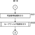
- FIG. 18 It is a flowchart explaining the example of the flow of decoding processing.
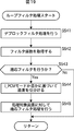
- 18 is a flowchart following FIG. 17 for explaining an example of the flow of the decoding process. It is a flowchart explaining the example of the flow of loop filter processing. It is a figure explaining the example of I_PCM information.
- It is a block diagram which shows the main structural examples of a personal computer. It is a block diagram which shows the main structural examples of a television receiver. It is a block diagram which shows the main structural examples of a mobile telephone. It is a block diagram which shows the main structural examples of a hard disk recorder. It is a block diagram which shows the main structural examples of a camera.
- FIG. 11 shows a configuration of an embodiment of an image coding apparatus that codes an image according to H.264 and MPEG (Moving Picture Experts Group) 4 Part 10 (AVC (Advanced Video Coding)) coding method.
- the image coding apparatus 100 shown in FIG. 1 is an apparatus that codes and outputs an image by a coding method based on the AVC standard.
- the image coding apparatus 100 includes an A / D conversion unit 101, a screen rearrangement buffer 102, an operation unit 103, an orthogonal conversion unit 104, a quantization unit 105, a lossless coding unit 106, and storage. It has a buffer 107.
- the image coding apparatus 100 further includes an inverse quantization unit 108, an inverse orthogonal transformation unit 109, an operation unit 110, a deblock filter 111, a frame memory 112, a selection unit 113, an intra prediction unit 114, a motion prediction / compensation unit 115, A selection unit 116 and a rate control unit 117 are included.
- the A / D converter 101 A / D converts the input image data, and outputs the image data to the screen rearrangement buffer 102 for storage.
- the screen rearrangement buffer 102 rearranges the images of frames in the stored display order into the order of frames for encoding in accordance with the GOP (Group of Picture) structure.
- the screen rearrangement buffer 102 supplies the image in which the order of the frames is rearranged to the calculation unit 103.
- the screen rearrangement buffer 102 also supplies the image in which the order of the frames is rearranged to the intra prediction unit 114 and the motion prediction / compensation unit 115.
- the operation unit 103 subtracts the predicted image supplied from the intra prediction unit 114 or the motion prediction / compensation unit 115 from the image read from the screen rearrangement buffer 102 via the selection unit 116, and makes the difference information orthogonal. It is output to the conversion unit 104.
- the operation unit 103 subtracts the predicted image supplied from the intra prediction unit 114 from the image read from the screen rearrangement buffer 102. Also, for example, in the case of an image on which inter coding is performed, the operation unit 103 subtracts the predicted image supplied from the motion prediction / compensation unit 115 from the image read from the screen rearrangement buffer 102.
- the orthogonal transformation unit 104 performs orthogonal transformation such as discrete cosine transformation and Karhunen-Loeve transformation on the difference information supplied from the calculation unit 103, and supplies the transformation coefficient to the quantization unit 105.
- the quantization unit 105 quantizes the transform coefficient output from the orthogonal transform unit 104.
- the quantization unit 105 sets a quantization parameter based on the information on the target value of the code amount supplied from the rate control unit 117 and performs quantization.
- the quantization unit 105 supplies the quantized transform coefficient to the lossless encoding unit 106.
- the lossless coding unit 106 performs lossless coding such as variable length coding and arithmetic coding on the quantized transform coefficients. Since the coefficient data is quantized under the control of the rate control unit 117, this code amount is the target value set by the rate control unit 117 (or approximate to the target value).
- the lossless encoding unit 106 acquires information indicating intra prediction from the intra prediction unit 114, and acquires information indicating an inter prediction mode, motion vector information, or the like from the motion prediction / compensation unit 115.
- the information which shows intra prediction is also hereafter called intra prediction mode information.
- the information which shows the information mode which shows inter prediction is also called inter prediction mode information hereafter.
- the lossless encoding unit 106 encodes the quantized transform coefficients, and also performs filter information, intra prediction mode information, inter prediction mode information, various information such as quantization parameters, and the like, on header information of encoded data. Make it part (multiplex).
- the lossless encoding unit 106 supplies the encoded data obtained by the encoding to the accumulation buffer 107 for accumulation.
- lossless encoding processing such as variable length coding or arithmetic coding is performed.
- variable-length coding H.264 is used.
- CAVLC Context-Adaptive Variable Length Coding
- arithmetic coding include CABAC (Context-Adaptive Binary Arithmetic Coding).
- the accumulation buffer 107 temporarily holds the encoded data supplied from the lossless encoding unit 106, and at a predetermined timing, the H.264 buffer is stored.
- the encoded image encoded in the H.264 / AVC format is output to a recording apparatus, a transmission path, or the like (not shown) in the subsequent stage.
- the transform coefficient quantized in the quantization unit 105 is also supplied to the inverse quantization unit 108.
- the inverse quantization unit 108 inversely quantizes the quantized transform coefficient by a method corresponding to the quantization by the quantization unit 105.
- the inverse quantization unit 108 supplies the obtained transform coefficient to the inverse orthogonal transform unit 109.
- the inverse orthogonal transform unit 109 performs inverse orthogonal transform on the supplied transform coefficient by a method corresponding to orthogonal transform processing by the orthogonal transform unit 104.
- the inverse orthogonal transform output (restored difference information) is supplied to the calculation unit 110.
- the calculation unit 110 predicts the inverse orthogonal transformation result supplied from the inverse orthogonal transformation unit 109, that is, the prediction supplied from the intra prediction unit 114 or the motion prediction / compensation unit 115 via the selection unit 116 to the restored difference information.
- the images are added to obtain a locally decoded image (decoded image).
- the calculation unit 110 adds the prediction image supplied from the intra prediction unit 114 to the difference information. Also, for example, when the difference information corresponds to an image on which inter coding is performed, the computing unit 110 adds the predicted image supplied from the motion prediction / compensation unit 115 to the difference information.
- the addition result is supplied to the deblocking filter 111 or the frame memory 112.
- the deblocking filter 111 removes block distortion of the decoded image by appropriately performing deblocking filter processing.
- the deblocking filter 111 supplies the filter processing result to the frame memory 112. Note that the decoded image output from the arithmetic unit 110 can be supplied to the frame memory 112 without passing through the deblocking filter 111. That is, the deblocking filter processing of the deblocking filter 111 can be omitted.
- the frame memory 112 stores the supplied decoded image, and outputs the stored decoded image as a reference image to the intra prediction unit 114 or the motion prediction / compensation unit 115 via the selection unit 113 at a predetermined timing. .
- the frame memory 112 supplies the reference image to the intra prediction unit 114 via the selection unit 113. Also, for example, when inter coding is performed, the frame memory 112 supplies the reference image to the motion prediction / compensation unit 115 via the selection unit 113.
- the selection unit 113 supplies the reference image to the intra prediction unit 114. Further, when the reference image supplied from the frame memory 112 is an image to be subjected to inter coding, the selection unit 113 supplies the reference image to the motion prediction / compensation unit 115.
- the intra prediction unit 114 performs intra prediction (in-screen prediction) of generating a predicted image using the pixel values in the processing target picture supplied from the frame memory 112 via the selection unit 113.
- the intra prediction unit 114 performs this intra prediction in a plurality of modes (intra prediction modes) prepared in advance.
- an intra 4 ⁇ 4 prediction mode, an intra 8 ⁇ 8 prediction mode, and an intra 16 ⁇ 16 prediction mode are defined for the luminance signal, and for the chrominance signal, It is possible to define a prediction mode independent of the luminance signal for each macroblock.
- intra 4 ⁇ 4 prediction mode one intra prediction mode is defined for each 4 ⁇ 4 luminance block and for intra 8 ⁇ 8 prediction mode, for each 8 ⁇ 8 luminance block become.
- intra 16 ⁇ 16 prediction mode and the color difference signal one prediction mode is defined for each macroblock.
- the intra prediction unit 114 generates predicted images in all candidate intra prediction modes, evaluates the cost function value of each predicted image using the input image supplied from the screen rearrangement buffer 102, and selects the optimum mode. select. When the optimal intra prediction mode is selected, the intra prediction unit 114 supplies the predicted image generated in the optimal mode to the computing unit 103 and the computing unit 110 via the selection unit 116.
- the intra prediction unit 114 appropriately supplies information such as intra prediction mode information indicating the adopted intra prediction mode to the lossless encoding unit 106.
- the motion prediction / compensation unit 115 uses the input image supplied from the screen rearrangement buffer 102 and the reference image supplied from the frame memory 112 via the selection unit 113 for an image to be inter coded. Motion prediction (inter prediction) is performed, motion compensation processing is performed according to the detected motion vector, and a prediction image (inter prediction image information) is generated. The motion prediction / compensation unit 115 performs such inter prediction in a plurality of modes (inter prediction modes) prepared in advance.
- the motion prediction / compensation unit 115 generates prediction images in all the candidate inter prediction modes, evaluates the cost function value of each prediction image, and selects an optimal mode.
- the motion prediction / compensation unit 115 supplies the generated predicted image to the calculation unit 103 and the calculation unit 110 via the selection unit 116.
- the motion prediction / compensation unit 115 supplies, to the lossless coding unit 106, inter prediction mode information indicating the adopted inter prediction mode, and motion vector information indicating the calculated motion vector.
- the selection unit 116 supplies the output of the intra prediction unit 114 to the calculation unit 103 and the calculation unit 110 in the case of an image to be subjected to intra coding, and the output of the motion prediction / compensation unit 115 in the case of an image to be inter coded. It is supplied to the calculation unit 103 and the calculation unit 110.
- the rate control unit 117 controls the rate of the quantization operation of the quantization unit 105 based on the compressed image stored in the storage buffer 107 so that overflow or underflow does not occur.
- FIG. 2 is a block diagram showing an example of a main configuration of an image decoding apparatus for realizing image compression by orthogonal transformation such as discrete cosine transformation or Karhunen-Loeve transformation and motion compensation.
- the image decoding apparatus 200 shown in FIG. 2 is a decoding apparatus corresponding to the image coding apparatus 100 of FIG.
- the encoded data encoded by the image encoding device 100 is supplied to the image decoding device 200 corresponding to the image encoding device 100 via any route, for example, a transmission path, a recording medium, etc. .
- the image decoding apparatus 200 includes an accumulation buffer 201, a lossless decoding unit 202, an inverse quantization unit 203, an inverse orthogonal transformation unit 204, an operation unit 205, a deblock filter 206, a screen rearrangement buffer 207, And a D / A converter 208.
- the image decoding apparatus 200 further includes a frame memory 209, a selection unit 210, an intra prediction unit 211, a motion prediction / compensation unit 212, and a selection unit 213.
- the accumulation buffer 201 accumulates the transmitted encoded data.
- the encoded data is encoded by the image encoding device 100.
- the lossless decoding unit 202 decodes the encoded data read from the accumulation buffer 201 at a predetermined timing in a method corresponding to the encoding method of the lossless encoding unit 106 in FIG. 1.
- intra prediction mode information is stored in the header portion of the encoded data.
- the lossless decoding unit 202 also decodes this intra prediction mode information, and supplies the information to the intra prediction unit 211.
- motion vector information is stored in the header portion of the coded data.
- the lossless decoding unit 202 also decodes this motion vector information, and supplies the information to the motion prediction / compensation unit 212.
- the inverse quantization unit 203 inversely quantizes the coefficient data (quantization coefficient) obtained by being decoded by the lossless decoding unit 202, using a method corresponding to the quantization method of the quantization unit 105 in FIG. That is, the inverse quantization unit 203 performs inverse quantization on the quantization coefficient in the same manner as the inverse quantization unit 108 in FIG.
- the inverse quantization unit 203 supplies the inversely quantized coefficient data, that is, the orthogonal transformation coefficient to the inverse orthogonal transformation unit 204.
- the inverse orthogonal transformation unit 204 performs inverse orthogonal transformation on the orthogonal transformation coefficient according to a scheme (similar to the inverse orthogonal transformation unit 109 in FIG. 1) corresponding to the orthogonal transformation scheme of the orthogonal transformation unit 104 in FIG. Decoding residual data corresponding to residual data before being orthogonally transformed in the coding apparatus 100 is obtained. For example, fourth-order inverse orthogonal transformation is performed.
- the decoded residual data obtained by the inverse orthogonal transform is supplied to the arithmetic unit 205. Further, the prediction image is supplied to the calculation unit 205 from the intra prediction unit 211 or the motion prediction / compensation unit 212 via the selection unit 213.
- Arithmetic unit 205 adds the decoded residual data and the predicted image to obtain decoded image data corresponding to the image data before the predicted image is subtracted by arithmetic unit 103 of image coding apparatus 100.
- the operation unit 205 supplies the decoded image data to the deblocking filter 206.
- the deblocking filter 206 removes block distortion of the supplied decoded image and then supplies the screen rearrangement buffer 207.
- the screen rearrangement buffer 207 rearranges the images. That is, the order of the frames rearranged for the order of encoding by the screen rearrangement buffer 102 in FIG. 1 is rearranged in the order of the original display.
- the D / A conversion unit 208 D / A converts the image supplied from the screen rearrangement buffer 207, and outputs the image to a display (not shown) for display.
- the output of the deblocking filter 206 is further supplied to a frame memory 209.
- the frame memory 209, the selection unit 210, the intra prediction unit 211, the motion prediction / compensation unit 212, and the selection unit 213 are the frame memory 112, the selection unit 113, the intra prediction unit 114, and the motion prediction / compensation unit of the image coding apparatus 100. 115 and the selection unit 116 respectively.
- the selection unit 210 reads out the image to be inter-processed and the image to be referred to from the frame memory 209, and supplies the image to the motion prediction / compensation unit 212. In addition, the selection unit 210 reads an image used for intra prediction from the frame memory 209 and supplies the image to the intra prediction unit 211.
- the intra prediction unit 211 generates a prediction image from the reference image acquired from the frame memory 209 based on this information, and supplies the generated prediction image to the selection unit 213.
- the motion prediction / compensation unit 212 acquires information (prediction mode information, motion vector information, reference frame information, flags, various parameters, and the like) obtained by decoding header information from the lossless decoding unit 202.
- the motion prediction / compensation unit 212 generates a prediction image from the reference image acquired from the frame memory 209 based on the information supplied from the lossless decoding unit 202, and supplies the generated prediction image to the selection unit 213.
- the selection unit 213 selects the prediction image generated by the motion prediction / compensation unit 212 or the intra prediction unit 211, and supplies the prediction image to the calculation unit 205.
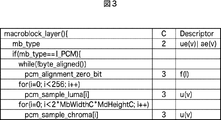
- Patent Document 1 By the way, as disclosed in Patent Document 1, there is a coding mode in which image data is coded and output, and a non-coding mode in which image data is output without being coded. There is a coding method in which whether to set the coding mode is selected in units of macroblocks, and the coding mode and the non-coding mode can be mixed in one picture. As shown in Patent Document 2, also in the AVC coding method, as shown in FIG. 3, I_PCM (Intra-block) for outputting image data without coding as one of the types of macroblocks (mb_type). Pulse code modulation (uncompressed) mode is supported.
- I_PCM Intra-block
- JM Job Model
- JM JM it is possible to select two mode determination methods of High Complexity Mode and Low Complexity Mode described below. Both calculate the cost function value regarding each prediction mode Mode, and select the prediction mode which makes this the minimum as the optimal mode with respect to the said block thru
- Equation (1) The cost function in the High Complexity Mode is as shown in Equation (1) below.
- ⁇ is the entire set of candidate modes for encoding the block or macroblock
- D is the difference energy between the decoded image and the input image when encoded in the prediction mode Mode
- ⁇ is a Lagrange undetermined multiplier given as a function of the quantization parameter
- R is a total code amount in the case of coding in the mode, which includes orthogonal transform coefficients.
- D is the difference energy between the predicted image and the input image, unlike in the case of the High Complexity Mode.
- QP2Quant QP
- HeaderBit is a code amount related to information belonging to the Header, such as a motion vector or a mode, which does not include an orthogonal transformation coefficient.
- Coding Unit also referred to as Coding Tree Block (CTB)
- CTB Coding Tree Block
- CU also referred to as Coding Tree Block
- the macroblock is fixed at a size of 16 ⁇ 16 pixels, whereas the size of a CU is not fixed, and will be specified in image compression information in each sequence.
- the CU having the largest size is referred to as a Largest Coding Unit (LCU), and the CU having the smallest size is referred to as a Smallest Coding Unit (SCU).
- LCU Largest Coding Unit
- SCU Smallest Coding Unit
- SPS sequence parameter set
- the size of these areas is specified, but each is limited to a square and a size represented by a power of two.
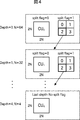
- FIG. 4 shows an example of a coding unit defined in HEVC.
- the size of LCU is 128, and the maximum hierarchical depth is 5.
- split_flag is “1”
- a 2N ⁇ 2N-sized CU is divided into an N ⁇ N-sized CU, which is one level lower.
- a CU is divided into prediction units (Prediction Units (PUs)), which are regions serving as processing units for intra or inter prediction (partial regions of images in units of pictures), and regions serving as processing units for orthogonal transformation. It is divided into transform units (Transform Units (TUs)), which are (partial areas of an image in picture units).
- Prediction Units PUs
- transform units Transform Units (TUs)
- TUs Transform Units
- Non-Patent Document 2 proposes a method (IBDI (Internal bit depth increase except frame memory)) for increasing the internal operation as shown in FIG.
- IBDI Internal bit depth increase except frame memory
- the bit depth is expanded, for example, from 8 bits to 12 bits.
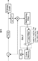
- Non-Patent Document 3 As shown in FIG. 5, an FIR filter is included in a motion compensation loop, and loop filter processing (BALF (Block-based Adaptive Loop Filter)) is adaptively performed by the filter.
- BALF Block-based Adaptive Loop Filter
- the deterioration in the reference image is minimized by obtaining the FIR filter coefficient by the Wiener filter so as to minimize the error with the input image, and the coding efficiency of the image compression information to be output It is possible to improve
- I_PCM mode is set in LCU units as in AVC, even in such a coding method, the unit of processing is larger than in AVC, for example, 128 ⁇ 128 pixel units. turn into.
- the modes of intra prediction and inter prediction are determined by calculating and comparing cost function values as described above. That is, prediction and encoding are performed in all modes, cost function values are calculated, optimal modes are selected, and encoded data is generated in the optimal modes.
- the coded data generated in the optimum mode is discarded, and the input image (non-coded data) is adopted as the coding result as it is. Therefore, when the I_PCM mode is selected, all processing for generating encoded data of the optimal mode becomes unnecessary processing. That is, when the unit of selection control in the I_PCM mode is increased, unnecessary processing is further increased. That is, as described above, if it is selected whether to adopt the I_PCM mode for each LCU, there is a possibility that the efficiency of the encoding process is further reduced. Thus, for example, it may be difficult to guarantee the real-time operation of CABAC.
- selection of the I_PCM mode can be controlled in more detail, and coding efficiency can be improved while suppressing reduction in the coding processing efficiency. Do. Also, according to the selection of the I_PCM mode, the presence or absence of the execution of IBDI or BALF can be appropriately controlled to further suppress the reduction in the efficiency of the encoding process.
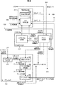
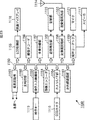
- FIG. 7 is a block diagram showing a main configuration example of the image coding apparatus.
- An image coding apparatus 300 shown in FIG. 7 is basically the same apparatus as the image coding apparatus 100 of FIG. 1 and codes image data.
- the image coding apparatus 300 includes an A / D conversion unit 301, a screen rearrangement buffer 302, an adaptive left shift unit 303, an operation unit 304, an orthogonal conversion unit 305, a quantization unit 306, and lossless coding. And an accumulation buffer 308.
- the image coding apparatus 300 further includes an inverse quantization unit 309, an inverse orthogonal transformation unit 310, an operation unit 311, a loop filter 312, an adaptive right shift unit 313, a frame memory 314, an adaptive left shift unit 315, a selection unit 316, and an intra A prediction unit 317, a motion prediction / compensation unit 318, a selection unit 319, and a rate control unit 320 are included.
- the image coding apparatus 300 further includes a PCM coding unit 321.
- the A / D converter 301 A / D converts the input image data.
- the A / D conversion unit 301 supplies the converted image data (digital data) to the screen rearrangement buffer 302 for storage.
- the screen rearrangement buffer 302 arranges the images of the stored display order frames according to the GOP (Group of Picture) structure in the order of frames for encoding. Change.
- the screen rearrangement buffer 302 supplies the image in which the order of the frames is rearranged to the adaptive left shift unit 303.
- the screen rearrangement buffer 302 also supplies the image in which the order of the frames is rearranged to the lossless encoding unit 307 and the PCM encoding unit 321.
- the adaptive left shift unit 303 is controlled by the PCM encoding unit 321, shifts the image data read from the screen rearrangement buffer 302 in the left direction, and increases its bit depth by a predetermined number of bits (for example, 4 bits). For example, the adaptive left shift unit 303 increases the bit depth of the image data read from the screen rearrangement buffer 302 from 8 bits to 12 bits. By thus increasing the bit depth, it is possible to improve the accuracy of the internal operation in each process such as orthogonal transformation process, quantization process, lossless encoding process, and prediction process, and to suppress an error.
- the left shift amount (bit amount) is arbitrary and may be a fixed value or variable. Further, under the control of the PCM encoding unit 321, this left shift process may be skipped (skipped).
- the adaptive left shift unit 303 supplies the image data after the left shift process (to the image data output from the screen rearrangement buffer 302 as it is when the process is omitted (skipped)) to the operation unit 304.
- the adaptive left shift unit 303 also supplies the image data to the intra prediction unit 317 and the motion prediction / compensation unit 318.
- the operation unit 304 uses the selection unit 319 to generate a predicted image supplied from the intra prediction unit 317 or the motion prediction / compensation unit 318 from the image supplied from the adaptive left shift unit 303. Subtract. Arithmetic unit 304 outputs the difference information to orthogonal transform unit 305.
- the operation unit 304 subtracts the predicted image supplied from the intra prediction unit 317 from the image supplied from the adaptive left shift unit 303. Also, for example, in the case of an image on which inter coding is performed, the operation unit 304 subtracts the predicted image supplied from the motion prediction / compensation unit 318 from the image supplied from the adaptive left shift unit 303.
- the orthogonal transformation unit 305 performs orthogonal transformation such as discrete cosine transformation and Karhunen-Loeve transformation on the difference information supplied from the calculation unit 304.
- the method of this orthogonal transformation is arbitrary.
- the orthogonal transform unit 305 supplies the transform coefficient to the quantization unit 306.
- the quantization unit 306 quantizes the transform coefficient supplied from the orthogonal transform unit 305 as in the case of the quantization unit 105.
- the quantization unit 306 sets a quantization parameter based on the information on the target value of the code amount supplied from the rate control unit 320 and performs the quantization. In addition, the method of this quantization is arbitrary.
- the quantization unit 306 supplies the quantized transform coefficient to the lossless encoding unit 307.
- the lossless coding unit 307 applies lossless coding such as variable-length coding and arithmetic coding to the transform coefficients quantized in the quantization unit 306. Since the coefficient data is quantized under the control of the rate control unit 320, this code amount is the target value set by the rate control unit 320 (or approximate to the target value).
- the lossless encoding unit 307 sets the input image (non-encoded data) supplied from the screen rearrangement buffer 302 as the encoding result (that is, actually) Encoding is skipped (skipped).
- the lossless encoding unit 307 acquires information indicating the mode of intra prediction from the intra prediction unit 317 and acquires information indicating the mode of inter prediction, motion vector information, or the like from the motion prediction / compensation unit 318. Further, the lossless encoding unit 307 obtains the filter coefficient used in the loop filter 312.
- the lossless encoding unit 307 encodes various kinds of information such as the filter coefficient, the information indicating the mode of intra prediction or inter prediction, and the quantization parameter in the same manner as in the case of the lossless encoding unit 106, and Make it part of header information (multiplex).
- the lossless encoding unit 307 supplies encoded data (including uncoded data in the case of I_PCM mode) obtained by encoding to the accumulation buffer 308 for accumulation.
- lossless encoding processing such as variable-length coding or arithmetic coding is performed.
- variable-length coding H.264 is used.
- CAVLC Context-Adaptive Variable Length Coding
- arithmetic coding include CABAC (Context-Adaptive Binary Arithmetic Coding).
- CABAC Context-Adaptive Binary Arithmetic Coding
- the accumulation buffer 308 temporarily holds the encoded data (including uncoded data in the I_PCM mode) supplied from the lossless encoding unit 307.
- the accumulation buffer 308 outputs, at a predetermined timing, the held encoded data to, for example, a recording device (recording medium), a transmission path, or the like (not shown) in the subsequent stage.
- the transform coefficient quantized in the quantization unit 306 is also supplied to the inverse quantization unit 309.
- the inverse quantization unit 309 inversely quantizes the quantized transform coefficient in a method corresponding to the quantization by the quantization unit 306 as in the case of the inverse quantization unit 108.
- the inverse quantization method may be any method as long as it corresponds to the quantization process by the quantization unit 306.
- the inverse quantization unit 309 supplies the obtained transform coefficient to the inverse orthogonal transform unit 310.
- the inverse orthogonal transform unit 310 performs inverse orthogonal transform on the transform coefficient supplied from the inverse quantization unit 309 by a method corresponding to orthogonal transform processing by the orthogonal transform unit 305 as in the case of the inverse orthogonal transform unit 109. Any method may be used as this inverse orthogonal transformation method as long as it corresponds to the orthogonal transformation processing by the orthogonal transformation unit 305.
- the inverse orthogonal transform output (restored difference information) is supplied to the calculation unit 311.
- the operation unit 311 performs the intra prediction unit 317 or motion prediction via the selection unit 319 according to the inverse orthogonal transformation result supplied from the inverse orthogonal transformation unit 310, that is, the restored difference information.
- the predicted image supplied from the compensation unit 318 is added to obtain a locally decoded (locally decoded) image (decoded image).
- the calculation unit 311 adds the prediction image supplied from the intra prediction unit 317 to the difference information. Also, for example, when the difference information corresponds to an image on which inter coding is performed, the calculation unit 311 adds the predicted image supplied from the motion prediction / compensation unit 318 to the difference information.
- the addition result (decoded image) is supplied to the loop filter 312 or the adaptive right shift unit 313.
- the loop filter 312 includes a deblocking filter, an adaptive loop filter, and the like, and appropriately filters the decoded image supplied from the calculation unit 311.
- the loop filter 312 removes block distortion of the decoded image by performing deblocking filter processing similar to that of the deblocking filter 111 on the decoded image.
- the loop filter 312 is controlled by the PCM encoding unit 321, and uses a Wiener filter for the deblock filter processing result (decoded image from which block distortion has been removed). Image quality is improved by performing loop filter processing. Note that this adaptive loop filter process may be skipped (skipped) under the control of the PCM encoding unit 321.
- the loop filter 312 may perform arbitrary filter processing on the decoded image.
- the loop filter 312 can also supply the filter coefficient used for the filtering process to the lossless encoding unit 307, as needed, to encode it.
- the loop filter 312 supplies the filter processing result (decoded image after filter processing) to the adaptive right shift unit 313.
- the decoded image output from the calculation unit 311 can be supplied to the adaptive right shift unit 313 without passing through the loop filter 312. That is, the filter processing by the loop filter 312 can be omitted (skipped).
- the adaptive right shift unit 313 is controlled by the PCM encoding unit 321, shifts the image data supplied from the operation unit 311 or the loop filter 312 to the right, and reduces its bit depth by a predetermined number of bits (for example, 4 bits). . That is, the adaptive right shift unit 313 shifts the bit depth of the image data to the right by the number of bits shifted to the left in the adaptive left shift unit 303 and shifts the bit depth of the image data to the left (read from the screen rearrangement buffer 302 State).
- the adaptive right shift unit 313 reduces the bit depth of the image data supplied from the calculation unit 311 or the loop filter 312 from 12 bits to 8 bits. By reducing the bit depth in this manner, it is possible to reduce the amount of image data stored in the frame memory.
- the right shift amount (bit amount) is arbitrary as long as it matches the left shift amount in the adaptive left shift unit 303. That is, it may be a fixed value or may be variable. Also, under the control of the PCM encoding unit 321, this right shift processing may be skipped (skipped).
- the adaptive right shift unit 313 supplies the image data after the right shift process to the frame memory 314 (when the process is skipped (skipped), the image data output from the operation unit 311 or the loop filter 312 is unchanged).
- the frame memory 314 stores the supplied decoded image, and outputs the stored decoded image as a reference image to the adaptive left shift unit 315 at a predetermined timing.
- the adaptive left shift unit 315 is a processing unit similar to the adaptive left shift unit 303, is controlled by the PCM encoding unit 321, and appropriately shifts the image data (reference image) read from the frame memory 314 in the left direction.
- the bit depth is increased by a predetermined number of bits (for example, 4 bits).
- the adaptive left shift unit 315 shifts the data of the reference image read from the frame memory 314 to the left according to the control of the PCM encoding unit 321, and the bit depth is the same as that of the adaptive left shift unit 303.
- Increase eg, change the bit depth from 8 bits to 12 bits).
- the adaptive left shift unit 315 supplies the image data after the left shift process to the selection unit 316.
- the bit depth of the reference image can be matched to the bit depth of the input image, and the reference image can be added to the input image. Further, the accuracy of the internal calculation such as the prediction process can be improved to suppress the error.
- the adaptive left shift unit 315 supplies the reference image read from the frame memory 314 to the selection unit 316 without increasing the bit depth according to the control of the PCM encoding unit 321.
- the selection unit 316 supplies the reference image supplied from the adaptive left shift unit 315 to the intra prediction unit 317 in the case of intra prediction. Further, in the case of inter prediction, the selection unit 316 supplies the reference image supplied from the adaptive left shift unit 315 to the motion prediction / compensation unit 318 as in the case of the selection unit 113.
- the intra prediction unit 317 performs intra prediction (in-screen prediction) of generating a predicted image using the reference image supplied from the adaptive left shift unit 315 via the selection unit 316.
- the intra prediction unit 317 performs this intra prediction in a plurality of modes (intra prediction modes) prepared in advance.
- the intra prediction unit 317 can also perform this intra prediction in any mode other than the mode specified in the AVC coding scheme.
- the intra prediction unit 317 generates predicted images in all candidate intra prediction modes, evaluates the cost function value of each predicted image using the input image supplied from the adaptive left shift unit 303, and selects the optimal mode. select. When the optimal intra prediction mode is selected, the intra prediction unit 317 supplies the predicted image generated in the optimal mode to the computation unit 304 or the computation unit 311 via the selection unit 319.
- the intra prediction unit 317 appropriately supplies information such as intra prediction mode information indicating the adopted intra prediction mode to the lossless encoding unit 307 and causes the information to be encoded.
- the motion prediction / compensation unit 318 uses the input image supplied from the adaptive left shift unit 303 and the reference image supplied from the adaptive left shift unit 315 via the selection unit 316 for an image to be inter coded. Then, motion prediction (inter prediction) is performed, motion compensation processing is performed according to the detected motion vector, and a predicted image (inter predicted image information) is generated.
- the motion prediction / compensation unit 318 performs such inter prediction in a plurality of modes (inter prediction modes) prepared in advance.
- the motion prediction / compensation unit 318 can also perform this inter prediction in any mode other than the mode specified in the AVC coding scheme.
- the motion prediction / compensation unit 318 generates prediction images in all the candidate inter prediction modes, evaluates the cost function value of each prediction image, and selects an optimal mode.
- the motion prediction / compensation unit 318 selects the optimal inter prediction mode, the motion prediction / compensation unit 318 supplies the prediction image generated in the optimal mode to the computation unit 304 or the computation unit 311 via the selection unit 319.
- the motion prediction / compensation unit 318 supplies the inter prediction mode information indicating the adopted inter prediction mode and the motion vector information indicating the calculated motion vector to the lossless encoding unit 307 for encoding.
- the selection unit 319 supplies the output of the intra prediction unit 317 to the calculation unit 304 and the calculation unit 311 in the case of an image in which intra coding is performed, and in the case of an image in which inter coding is performed.
- the output of the motion prediction / compensation unit 318 is supplied to the calculation unit 304 and the calculation unit 311.
- the rate control unit 320 controls the rate of the quantization operation of the quantization unit 306 based on the code amount of the encoded data accumulated in the accumulation buffer 308 so that an overflow or an underflow does not occur.
- the rate control unit 320 supplies the code amount (generated code amount) of the encoded data stored in the storage buffer 308 to the PCM encoding unit 321.
- the PCM encoding unit 321 compares the code amount supplied from the rate control unit 320 with the data amount of the input image supplied from the screen rearrangement buffer 302, and selects whether to adopt the I_PCM mode. At this time, the PCM encoding unit 321 performs this selection in CU units smaller than the LCU. That is, the PCM encoding unit 321 controls in more detail whether or not the I_PCM mode is selected.
- the PCM coding unit 321 controls the operations of the lossless coding unit 307, the adaptive left shift unit 303, the adaptive right shift unit 313, the adaptive left shift unit 315, and the loop filter 312 according to the selection result.
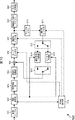
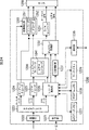
- FIG. 8 is a block diagram showing a main configuration example of the lossless encoding unit 307, the PCM encoding unit 321, and the loop filter 312 of FIG.
- the lossless encoding unit 307 includes a NAL (Network Abstraction Layer) encoding unit 331 and a CU encoding unit 332.
- NAL Network Abstraction Layer
- the NAL encoding unit 33 for example, NAL such as a sequence parameter set (SPS (Sequence Parameter Set) or PPS (Picture Parameter Set)) based on a user instruction input via a user interface (not shown) or specifications and the like.
- the NAL coding unit 331 supplies the coded NAL (NAL data) to the accumulation buffer 308, and the encoded VCL (Video Coding Layer) supplied from the CU coding unit 332 to the accumulation buffer 308. To be added to the CU data.
- SPS Sequence Parameter Set
- PPS Picture Parameter Set
- the CU encoding unit 332 is controlled by the PCM encoding unit 321 (based on the On / Off control signal supplied from the PCM encoding unit 321) to encode VCL. For example, when the I_PCM mode is not selected by the PCM encoding unit 321 (when a control signal indicating “On” is supplied from the PCM encoding unit 321), the CU encoding unit 332 quantizes each CU. Encode the orthogonal transform coefficients. The CU encoding unit 332 supplies the encoded data (CU data) of each encoded CU to the accumulation buffer 308.
- the CU encoding unit 332 when the I_PCM mode is selected by the PCM encoding unit 321 (when a control signal indicating “Off” is supplied from the PCM encoding unit 321), the CU encoding unit 332 generates the screen rearrangement buffer 302. Are supplied to the accumulation buffer 308 as a coding result (CU data).
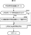
- the CU encoding unit 332 also encodes a flag (I_PCM_flag), which is supplied from the PCM encoding unit 321 and indicates whether the encoding mode is the I_PCM mode, and supplies it to the accumulation buffer 308 as CU data. . Further, the CU encoding unit 332 encodes information related to filter processing such as an adaptive filter flag and a filter coefficient supplied from the loop filter 312, and supplies the encoded information as CU data to the accumulation buffer 308.
- I_PCM_flag a flag supplied from the PCM encoding unit 321 and indicates whether the encoding mode is the I_PCM mode
- the method of encoding by the CU encoding unit 332 is arbitrary (for example, CABAC, CAVLC, etc.).
- the NAL data and CU data supplied to the accumulation buffer 308 are combined and accumulated.
- the PCM encoding unit 321 controls whether to select the I_PCM mode using the code amount of encoded data obtained by encoding the orthogonal transformation coefficient quantized by the CU encoding unit 332. Do.
- the encoded data supplied to the accumulation buffer 308 is adopted as it is as the encoding result of the quantized orthogonal transformation coefficient of the CU. Therefore, the CU encoding unit 332 may perform only encoding of additional information such as I_PCM_flag.
- the CU encoding unit 332 sets the input pixel value of the corresponding CU supplied from the screen rearrangement buffer 302 as the encoding result (CU data) in the accumulation buffer 308. Supply. Therefore, in this case, the already supplied encoded data of the CU (encoded data obtained by encoding the quantized orthogonal transformation coefficient) is discarded. That is, all the processes related to the generation of the encoded data become redundant processes.
- the PCM encoding unit 321 includes an I_PCM_flag generation unit 341 and a PCM determination unit 342.
- the I_PCM_flag generation unit 341 generates I_PCM_flag according to the determination of the PCM determination unit 342, and determines the value thereof.
- the I_PCM_flag generation unit 341 supplies the generated I_PCM_flag to the CU encoding unit 332 of the lossless encoding unit 307. For example, when the PCM determination unit 342 selects the I_PCM mode, the I_PCM_flag generation unit 341 sets the value of I_PCM_flag to a value (for example, “1”) indicating that the I_PCM mode is selected, and the I_PCM_flag is a CU code It supplies to the conversion unit 332.
- the I_PCM_flag generation unit 341 sets the value of I_PCM_flag to a value (for example, “0”) indicating that the I_PCM mode is not selected. , And supplies the I_PCM_flag to the CU encoding unit 332.
- the PCM determination unit 342 determines whether to set the coding mode to the I_PCM mode.
- the PCM determination unit 342 obtains the data amount of the input pixel value supplied from the screen rearrangement buffer 302, compares it with the generated code amount supplied from the rate control unit 320, and selects the I_PCM mode based on the comparison result. Decide whether to The PCM determination unit 342 controls the operation according to the selection result by supplying the On / Off control signal indicating the selection result to the CU encoding unit 332 and the I_PCM_flag generation unit 341.
- the PCM determination unit 342 when the data amount of the input pixel value is larger than the generated code amount, the PCM determination unit 342 does not select the I_PCM mode. In this case, the PCM determination unit 342 supplies a control signal indicating “On” to the CU encoding unit 332, and causes the CU encoding unit 332 to encode the quantized orthogonal transformation coefficient. Also, the PCM determination unit 342 supplies a control signal indicating “On” to the I_PCM_flag generation unit 341, and generates I_PCM_flag of a value (for example, “0”) indicating that the I_PCM mode is not selected.
- the PCM determination unit 342 selects the I_PCM mode.
- the PCM determination unit 342 supplies a control signal indicating "Off" to the CU encoding unit 332, and causes the input pixel value to be output as an encoding result (CU data).
- the PCM determination unit 342 supplies a control signal indicating "Off” to the I_PCM_flag generation unit 341, and generates I_PCM_flag of a value (for example, "1") indicating that the I_PCM mode is selected.
- the PCM determination unit 342 performs determination of whether or not to select such an I_PCM mode for each size (an arbitrary hierarchy) of CUs set in the sequence parameter set, not only the LCU. Can. This makes it possible, for example, to limit the generation of a large number of bits in the low QP by the I_PCM mode in units of smaller CUs, so that the code amount (unsigned by I_PCM mode) Not only can the control of the volume data (including the amount of data) be performed in more detail, but also the redundant processing that occurs in the I_PCM mode can be reduced.
- the PCM determination unit 342 supplies the On / Off control signal indicating the selection result to the adaptive left shift unit 303, the adaptive right shift unit 313, and the adaptive left shift unit 315 to control the IBDI according to the selection result. I do. That is, when the CU is in the I_PCM mode, the PCM determination unit 342 controls so that the adaptive shift device does not perform the process of increasing and decreasing the bit precision.
- the PCM determination unit 342 supplies a control signal indicating “On” to the adaptive left shift unit 303, the adaptive right shift unit 313, and the adaptive left shift unit 315, and performs left shift processing. Or execute right shift processing so that extension of bit precision in internal processing is performed.
- the PCM determination unit 342 supplies a control signal indicating “Off” to the adaptive left shift unit 303, the adaptive right shift unit 313, and the adaptive left shift unit 315, The left shift process and the right shift process are skipped (skipped) so that extension of bit precision in internal processing is not performed.
- the PCM determination unit 342 can eliminate such redundant processing by performing the processing as described above.
- the PCM determination unit 342 controls the adaptive loop filter processing (BALF) according to the selection result by supplying the On / Off control signal indicating the selection result to the loop filter 312. That is, when the CU is in the I_PCM mode, the PCM determination unit 342 performs control such that the adaptive loop filter process by the loop filter 312 is not performed.
- BALF adaptive loop filter processing
- the PCM determination unit 342 supplies a control signal indicating “On” to the loop filter 312 so that adaptive loop filter processing is performed.
- the PCM determination unit 342 supplies a control signal indicating “Off” to the loop filter 312 to skip (skip) adaptive loop filter processing.
- the PCM determination unit 342 can eliminate such redundant processing by performing the processing as described above.
- the loop filter 312 includes a deblocking filter 351, a pixel sorting unit 352, a filter coefficient calculation unit 353, and a filtering unit 354.
- the deblocking filter 351 removes block distortion by performing deblocking filter processing on the decoded image (pixel values before deblocking filter) supplied from the calculation unit 311.
- the CU adjacent to the CU is not necessarily processed in the I_PCM mode. Therefore, even if the CU is processed in I_PCM mode, block distortion may occur. Therefore, deblocking filter processing is performed regardless of whether the CU is in the I_PCM mode.
- the deblocking filter 351 supplies the filter processing result (pixel value after deblocking filter) to the pixel sorting unit 352.
- the pixel sorting unit 352 performs adaptive loop filter processing on each filter processing result (pixel value after deblocking filter) according to the value of the On / Off control signal supplied from the PCM determination unit 342, and adaptive loop filter Sort into pixel values not to be processed.
- the pixel sorting unit 352 sorts the deblock filtered pixel values of the CU into pixel values on which the adaptive loop filter process is performed.
- the pixel sorting unit 352 does not perform adaptive loop filter processing on the pixel value after deblocking filter of the CU. Sort by value.
- the pixel sorting unit 352 supplies the pixel value (pixel value after deblocking filter) of each sorted pixel to the filter coefficient calculation unit 353.
- the filter coefficient calculation unit 353 sets the filter coefficient (FIR filter coefficient) of the adaptive loop filter for the pixel value classified into one to be subjected to the adaptive loop filter processing among the supplied pixel values after deblocking filter as the input image Calculate with a Wiener Filter so as to minimize the error with. That is, the filter coefficient calculation unit 353 calculates filter coefficients except for pixels processed in the I_PCM mode.
- the filter coefficient calculation unit 353 supplies the post-deblocking filter pixel value and the calculated filter coefficient to the filtering unit 354.
- the filtering unit 354 performs adaptive loop filter processing (adaptive loop filter processing) on the pixel values classified to one performing adaptive loop filter processing using the supplied filter coefficient.
- the filtering unit 354 supplies the pixel value after the filtering process and the pixel value classified to one that does not perform the adaptive loop filtering process to the adaptive right shift unit 313 as a pixel value after adaptive filtering.
- the filtering unit 354 also generates an adaptive filter flag (on / off_flag), which is filter identification information indicating whether or not filtering has been performed, for each predetermined block that is set independently of the CU.
- an adaptive filter flag (on / off_flag)
- the method of setting the value of this adaptive filter flag is arbitrary.
- the adaptive filter flag when adaptive loop filter processing is performed on some or all of the pixels in the block (current block) to be processed, the adaptive filter flag has a value indicating that filter processing has been performed (for example, “ 1) may be set. Also, for example, when all the pixels in the block are not subjected to adaptive loop filter processing, the adaptive filter flag is set to a value (for example, “0”) indicating that filter processing is not performed. It is also good.
- the value of the adaptive filter flag may be set based on other criteria.
- the filtering unit 354 supplies the generated adaptive filter flag to the CU encoding unit 332 of the lossless encoding unit 307, causes the CU encoding unit 332 to perform encoding, and provides the decoding side.
- the value of the adaptive filter flag is a value (for example, “0”) indicating that the filtering process is not performed, the provision to the decoding side is omitted (the adaptive filter flag is not provided to the decoding side) Can).
- the value of the adaptive filter flag is a value (for example, “0”) indicating that filter processing is not performed
- the coding method of the lossless encoding unit 307 (CU encoding unit 332) is VLC.
- the filtering unit 354 omits the supply of the adaptive filter flag (does not provide it to the decoding side).
- the value of the adaptive filter flag is a value (for example, “0”) indicating that filter processing is not performed
- the coding method of the lossless coding unit 307 (CU coding unit 332) is
- the filtering unit 354 supplies this adaptive filter flag to the CU encoding unit 332 of the lossless encoding unit 307 (provides to the decoding side).
- the filtering unit 354 supplies the filter coefficient used for the adaptive loop filter processing to the CU coding unit 332 of the lossless coding unit 307, causes the CU coding unit 332 to code, and provides the same to the decoding side.
- FIG. 9 is a block diagram showing an example of the main configuration of the PCM determination unit 342 of FIG.
- the PCM determination unit 342 includes an input data amount calculation unit 361, a PCM determination unit 362, an encoding control unit 363, an adaptive shift control unit 364, and a filter control unit 365.
- the input data amount calculation unit 361 calculates the input data amount which is the data amount of the input pixel value supplied from the screen rearrangement buffer 302 for the CU, and supplies the calculated input data amount to the PCM determination unit 362.
- the PCM determination unit 362 acquires the generated code amount (generated bit) supplied from the rate control unit 320, compares it with the input data amount supplied from the input data amount calculation unit 361, and based on the comparison result, It is determined whether or not to select the I_PCM mode for. That is, the PCM determination unit 362 determines whether to select the I_PCM mode for each CU of an arbitrary hierarchy.
- the PCM determination unit 362 supplies the determination result to the coding control unit 363, the adaptive shift control unit 364 and the filter control unit 365.
- the encoding control unit 363 instructs the CU encoding unit 332 and the I_PCM_flag generation unit 341 to turn On / On.
- the Off control signal is supplied.
- the coding control unit 363 can control the coding mode for each CU of an arbitrary layer.
- the encoding control unit 363 can not only control the code amount (including the data amount of non-coded data in the I_PCM mode) in more detail, but also performs redundant processing when the I_PCM mode is selected. Can be reduced.
- the adaptive shift control unit 364 sets the adaptive left shift unit 303, the adaptive right shift unit 313, and the adaptive left shift based on the determination result (information indicating whether or not the I_PCM mode is selected) supplied from the PCM determination unit 362 An On / Off control signal is supplied to the unit 315.
- the adaptive shift control unit 364 can perform control so as not to extend the bit depth in the internal operation in the I_PCM mode. Thereby, the adaptive shift control unit 364 can reduce redundant processing.
- the filter control unit 365 supplies an On / Off control signal to the pixel sorting unit 352 based on the determination result (information indicating whether or not the I_PCM mode is selected) supplied from the PCM determination unit 362.
- the filter control unit 365 can perform control so as not to execute the adaptive loop filter process in the I_PCM mode. Thus, the filter control unit 365 can reduce redundant processing.
- the image coding apparatus 300 can reduce redundant processing and suppress reduction in the efficiency of coding processing.
- the image coding apparatus 300 can perform selection of the I_PCM mode (non-compression mode) in more detail (for each small data unit), and can improve coding efficiency. Therefore, the image coding apparatus 300 can improve the coding efficiency while suppressing the reduction in the coding processing efficiency.
- step S301 the A / D converter 301 A / D converts the input image.
- step S302 the screen rearrangement buffer 302 stores the A / D converted image, and performs rearrangement from the display order of each picture to the coding order.
- step S303 the adaptive left shift unit 303 adaptively shifts the input image to the left based on the control of the PCM encoding unit 321.
- step S304 the adaptive left shift unit 315 adaptively left shifts the reference image.
- step S305 the intra prediction unit 317 performs intra prediction processing in the intra prediction mode using the reference image shifted to the left in step S304.
- step S306 the motion prediction / compensation unit 318 performs inter motion prediction processing for performing motion prediction or motion compensation in the inter prediction mode using the reference image shifted to the left in step S304.
- the process of shifting the bit depth of the reference image to the left may be performed when the reference image is read out from the frame memory 314 in the intra prediction process or the inter motion prediction process.
- step S307 the selection unit 319 determines the optimal mode based on the cost function values output from the intra prediction unit 317 and the motion prediction / compensation unit 318. That is, the selection unit 319 selects one of the prediction image generated by the intra prediction unit 317 and the prediction image generated by the motion prediction / compensation unit 318.
- selection information indicating which prediction image is selected is supplied to one of the intra prediction unit 317 and the motion prediction / compensation unit 318 from which the prediction image is selected.
- the intra prediction unit 317 supplies intra prediction mode information indicating the optimal intra prediction mode and the like to the lossless encoding unit 307.
- the motion prediction / compensation unit 318 sends the lossless encoding unit 307 information indicating the optimal inter prediction mode and, if necessary, information according to the optimal inter prediction mode. Output.
- information according to the optimal inter prediction mode motion vector information, flag information, reference frame information and the like can be mentioned.
- step S308 the computing unit 304 computes the difference between the image whose bit depth has been left shifted by the process of step S303 and the predicted image selected by the process of step S307.
- the prediction image is supplied from the motion prediction / compensation unit 318 when performing inter prediction, and from the intra prediction unit 317 when performing intra prediction, to the computation unit 304 via the selection unit 319.
- the amount of difference data is reduced compared to the original image data. Therefore, the amount of data can be compressed as compared to the case of encoding the image as it is.
- step S309 the orthogonal transformation unit 305 orthogonally transforms the difference information generated by the process of step S308. Specifically, orthogonal transformation such as discrete cosine transformation and Karhunen-Loeve transformation is performed, and transformation coefficients are output.
- orthogonal transformation such as discrete cosine transformation and Karhunen-Loeve transformation is performed, and transformation coefficients are output.
- step S310 the quantization unit 306 quantizes the orthogonal transformation coefficient obtained by the process of step S309.
- step S311 the lossless encoding unit 307 encodes the transform coefficient quantized in the process of step S310. That is, lossless coding such as variable-length coding or arithmetic coding is performed on the difference image.
- the lossless encoding unit 307 encodes the quantization parameter calculated in step S310 and adds the encoded parameter to the encoded data. Also, the lossless encoding unit 307 encodes information on the mode of the predicted image selected in the process of step S307, and adds the encoded data obtained by encoding the difference image. That is, the lossless encoding unit 307 also encodes the optimal intra prediction mode information supplied from the intra prediction unit 317 or the information according to the optimal inter prediction mode supplied from the motion prediction / compensation unit 318, etc. Append to data.
- the lossless encoding unit 307 encodes the filter coefficient and the flag information acquired from the loop filter 312 and adds the encoded information to the encoded data. Furthermore, the lossless encoding unit 307 also encodes NAL data.
- step S312 the accumulation buffer 308 accumulates the encoded data output from the lossless encoding unit 307.
- the encoded data stored in the storage buffer 308 is appropriately read and transmitted to the decoding side via a transmission path or a recording medium.
- step S313 the rate control unit 320 calculates the code amount (generated code amount) of the encoded data accumulated in the accumulation buffer 308 by the process of step S312, and based thereon, the overflow or underflow does not occur.
- the rate of the quantization operation of the quantization unit 306 is controlled. Further, the rate control unit 320 supplies the generated code amount to the PCM encoding unit 321.
- step S314 the PCM encoding unit 321 performs PCM encoding control processing using the generated code amount calculated in step S313.
- step S315 the lossless encoding unit 307 performs PCM encoding processing according to the control of the PCM encoding unit 321.
- step S316 the inverse quantization unit 309 to the frame memory 314 locally decode the difference information quantized in the process of step S310, and execute a reference image generation process of generating a reference image.
- step S316 When the process of step S316 ends, the encoding process ends. This encoding process is repeatedly performed, for example, for each CU.
- step S331 the PCM determination unit 362 of the PCM determination unit 342 supplies the encoded data of the quantized orthogonal transformation coefficient of the CU, which is supplied from the rate control unit 320. Acquire the generated code amount.
- step S332 the input data amount calculation unit 361 calculates the input data amount of the input pixel value of the CU.
- step S333 the PCM determination unit 362 compares the code amount acquired in step S331 with the input data amount calculated in step S332, and determines whether or not coding is to be performed in the I_PCM mode.
- step S334 the I_PCM_flag generating unit 341 generates I_PCM_flag based on the On / Off control signal indicating the determination result of step S333 supplied by the encoding control unit 363.
- step S335 the encoding control unit 363 controls the encoding of CU data by supplying the On / Off control signal indicating the determination result of step S333 to the CU encoding unit 332.
- step S336 the adaptive shift control unit 364 supplies the On / Off control signal indicating the determination result of step S333 to the adaptive left shift unit 303, the adaptive right shift unit 313, and the adaptive left shift unit 315. , Control the adaptive shift process.
- step S 337 the encoding control unit 363 controls the adaptive loop filter processing by supplying the On / Off control signal indicating the determination result of step S 333 to the pixel sorting unit 352 of the loop filter 312.
- step S337 ends, the PCM determination unit 342 ends the PCM encoding control process, returns the process to step S314 in FIG. 10, and executes the processes of step S315 and subsequent steps.
- step S351 the CU encoding unit 332 determines whether to perform encoding in the I_PCM mode. If it is controlled by the above-described PCM coding control processing to perform coding in the I_PCM mode, the CU coding unit 332 proceeds with the process to step S352. In step S352, the CU encoding unit 332 selects the input pixel value of the CU as an encoding result. The CU encoding unit 332 discards the CU data of the CU of the accumulation buffer 308, and accumulates the input pixel value in the accumulation buffer 308.
- step S352 When the process of step S352 ends, the CU encoding unit 332 advances the process to step S353. If it is determined in step S351 that the encoding is not performed in the I_PCM mode, the CU encoding unit 332 causes the process to proceed to step S353.
- step S 353 the CU encoding unit 332 encodes I_PCM_flag generated by the above-described PCM encoding control process, and causes the accumulation buffer 308 to accumulate the I_PCM_flag.
- step S353 ends, the CU encoding unit 332 ends the PCM encoding process, returns the process to step S315 in FIG. 10, and executes the processes of step S316 and subsequent steps.
- the adaptive left shift unit 315 determines whether the I_PCM mode is selected based on the control of the adaptive shift control unit 364 in step S371.
- the I_PCM mode is selected, bit depth expansion in internal calculation is not performed, so prediction processing is redone. That is, when it is determined that the I_PCM mode is selected, the adaptive left shift unit 315 advances the process to step S372 without performing the left shift process on the reference image.
- step S372 the intra prediction unit 317 performs intra prediction processing using a reference image whose bit depth is not left shifted.
- step S 373 the motion prediction / compensation unit 318 performs inter motion prediction processing using a reference image whose bit depth has not been left shifted.
- step S 374 the selection unit 319 determines the optimal mode based on the cost function values output from the intra prediction unit 317 and the motion prediction / compensation unit 318. That is, the selection unit 319 selects one of the prediction image generated by the intra prediction unit 317 and the prediction image generated by the motion prediction / compensation unit 318.
- selection information indicating which prediction image is selected is supplied to one of the intra prediction unit 317 and the motion prediction / compensation unit 318 from which the prediction image is selected.
- the intra prediction unit 317 supplies intra prediction mode information indicating the optimal intra prediction mode and the like to the lossless encoding unit 307.
- the motion prediction / compensation unit 318 sends the lossless encoding unit 307 information indicating the optimal inter prediction mode and, if necessary, information according to the optimal inter prediction mode. Supply.
- information according to the optimal inter prediction mode motion vector information, flag information, reference frame information and the like can be mentioned.
- step S375 the computing unit 304 computes the difference between the input image whose bit depth has not been left-shifted and the predicted image selected in the process of step S374.
- the prediction image is supplied from the motion prediction / compensation unit 318 when performing inter prediction, and from the intra prediction unit 317 when performing intra prediction, to the computation unit 304 via the selection unit 319.
- step S376 the orthogonal transformation unit 305 orthogonally transforms the difference information generated by the process of step S375. Specifically, orthogonal transformation such as discrete cosine transformation and Karhunen-Loeve transformation is performed, and transformation coefficients are output.
- step S377 the quantization unit 306 quantizes the orthogonal transformation coefficient obtained by the process of step S376.
- the quantization unit 306 advances the process to step S378, and generation of a reference image is performed using the orthogonal transformation coefficient (data not subjected to the left shift process) quantized in step S377. To be done.
- step S371 when it is determined in step S371 that the current mode is not the I_PCM mode, the adaptive left shift unit 315 skips (skips) each process of steps S372 to S377, and advances the process to step S378. That is, when it is not in the I_PCM mode, generation of a reference image is performed using the orthogonal transformation coefficient (data shifted to the left) quantized in step S310 in FIG.
- step S3708 the inverse quantization unit 309 inversely quantizes the quantized orthogonal transformation coefficient (also referred to as a quantization coefficient) with the characteristic corresponding to the characteristic of the quantization unit 306.
- step S379 the inverse orthogonal transformation unit 310 performs inverse orthogonal transformation on the orthogonal transformation coefficient obtained by the process of step S378 with a characteristic corresponding to the characteristic of the orthogonal transformation unit 305.
- step S380 the calculation unit 311 adds the prediction image to the locally decoded difference information, and generates a locally decoded image (an image corresponding to an input to the calculation unit 304).
- the computing unit 311 adds the prediction image not subjected to the left shift process to the difference information not subjected to the left shift process to generate a decoded image not subjected to the left shift process.
- the computing unit 311 adds the prediction image subjected to the left shift process to the difference information subjected to the left shift process, and generates a decoded image subjected to the left shift process.
- step S 381 the loop filter 312 performs loop filter processing on the local decoded image obtained by the processing of step S 380 based on the control of the filter control unit 365, and performs deblocking filter processing, adaptive loop filter processing, etc. As appropriate, perform loop filter processing including
- step S 382 the adaptive right shift unit 313 determines, based on the control of the adaptive shift control unit 364, whether or not the I_PCM mode has been selected. If it is determined that the I_PCM mode is not selected, the adaptive right shifting unit 313 proceeds with the process to step S383.
- the adaptive right shift unit 313 performs the filter processing result (decoded image) obtained by the loop filter processing in step S381 in step S383. Perform a right shift adaptively to the bit depth of.
- the adaptive right shift unit 313 causes the process to proceed to step S384.
- step S382 If it is determined in step S382 that the I_PCM mode is selected, the adaptive right shifting unit 313 proceeds with the process to step S384 without performing the right shift process.
- step S384 the frame memory 314 stores the decoded image.
- the frame memory 314 ends the reference image generation process, returns the process to step S316 in FIG. 10, and ends the encoding process.
- the deblock filter 351 of the loop filter 312 performs the deblock filter process on the decoded image (pre-deblock filter pixel value) supplied from the calculation unit 311 in step S401.
- step S402 the pixel sorting unit 352 is controlled by the filter control unit 365 of the PCM determination unit 342, and sorts the pixels of the decoded image based on whether or not it is in the I_PCM mode.
- step S403 the filter coefficient calculation unit 353 calculates filter coefficients for pixels (processing target pixels) classified to perform filter processing.
- step S404 the filtering unit 354 performs adaptive filter processing on the processing target pixel using the filter coefficient calculated in step S403.
- step S405 the filtering unit 354 sets an adaptive filter flag for the processing target block, supplies the adaptive filter flag and the filter coefficient to the CU encoding unit 332, and causes the CU encoding unit 332 to perform encoding.
- step S405 ends, the loop filter 312 ends the loop filter process, returns the process to step S381 in FIG. 13, and executes the processes of step S382 and subsequent steps.
- the image coding apparatus 300 can improve the coding efficiency while suppressing the reduction in the coding process efficiency.
- FIG. 15 is a block diagram showing a main configuration example of the image decoding apparatus.
- the image decoding device 500 shown in FIG. 15 is basically the same as the image decoding device 200 of FIG. 2, and decodes encoded data obtained by encoding image data.
- the image decoding apparatus 500 shown in FIG. 15 is a decoding apparatus corresponding to the image coding apparatus 300 of FIG.
- the encoded data encoded by the image encoding device 300 is supplied to the image decoding device 500 via an arbitrary route such as a transmission path or a recording medium, for example, and is decoded.
- the image decoding apparatus 500 includes an accumulation buffer 501, a lossless decoding unit 502, an inverse quantization unit 503, an inverse orthogonal transformation unit 504, an operation unit 505, a loop filter 506, an adaptive right shift unit 507, and a screen.
- a reordering buffer 508 and a D / A converter 509 are included.
- the image decoding apparatus 500 further includes a frame memory 510, an adaptive left shift unit 511, a selection unit 512, an intra prediction unit 513, a motion prediction / compensation unit 514, and a selection unit 515.
- the image decoding apparatus 500 further includes a PCM decoding unit 516.
- the accumulation buffer 501 accumulates the transmitted encoded data as in the case of the accumulation buffer 201.
- the encoded data is encoded by the image encoding device 300.
- the lossless decoding unit 502 reads the encoded data from the accumulation buffer 501 at a predetermined timing, and decodes the data using a method corresponding to the encoding method of the lossless encoding unit 307 in FIG. At that time, the lossless decoding unit 502 supplies I_PCM_flag included in the encoded data to the PCM decoding unit 516, and determines whether or not the I_PCM mode (non-compression mode) is selected.
- the lossless decoding unit 502 supplies the CU data to the inverse quantization unit 503 according to the control of the PCM decoding unit 516.
- the lossless decoding unit 502 decodes the CU data according to the control of the PCM decoding unit 516, and the inverse quantization unit Supply to 503.
- intra prediction mode information is stored in the header part of coding data.
- the lossless decoding unit 502 also decodes this intra prediction mode information, and supplies the information to the intra prediction unit 513.
- motion vector information and inter prediction mode information are stored in the header portion of the encoded data.
- the lossless decoding unit 502 also decodes the motion vector information and the inter prediction mode information, and supplies the information to the motion prediction / compensation unit 514.
- the coefficient data (quantization coefficient) supplied from the lossless decoding unit 502 is compared with that of the quantization unit 306 in FIG. Inverse quantization is performed by a method corresponding to the quantization method. That is, the inverse quantization unit 503 performs inverse quantization of the quantization coefficient in the same manner as the inverse quantization unit 309 in FIG. 7.
- the inverse quantization unit 503 supplies the inversely quantized coefficient data, that is, the orthogonal transformation coefficient to the inverse orthogonal transformation unit 504.
- the inverse quantization unit 503 supplies the CU data (image data not encoded) supplied from the lossless decoding unit 502 to the inverse orthogonal transformation unit 504.
- the inverse orthogonal transform unit 504 When the inverse orthogonal transform unit 504 is not in the I_PCM mode, as in the case of the inverse orthogonal transform unit 204, a scheme corresponding to the orthogonal transform scheme of the orthogonal transform unit 305 in FIG. 7 (similar to the inverse orthogonal transform unit 310 in FIG. Inverse orthogonal transform the orthogonal transform coefficient by The inverse orthogonal transformation unit 504 obtains decoded residual data corresponding to residual data before orthogonal transformation in the image coding apparatus 300 by this inverse orthogonal transformation processing. For example, fourth-order inverse orthogonal transformation is performed. The inverse orthogonal transform unit 504 supplies the decoding residual data obtained by the inverse orthogonal transform to the operation unit 505.
- the inverse orthogonal transform unit 504 supplies the CU data (uncoded image data) supplied from the inverse quantization unit 503 to the operation unit 505.
- the prediction image is supplied to the calculation unit 505 from the intra prediction unit 513 or the motion prediction / compensation unit 514 via the selection unit 515.
- the calculating unit 505 When not in the I_PCM mode, the calculating unit 505 adds the decoded residual data and the predicted image as in the case of the calculating unit 205, and before the predicted image is subtracted by the calculating unit 304 of the image coding apparatus 300.
- the decoded image data corresponding to the image data of The operation unit 505 supplies the decoded image data to the loop filter 506.
- the operation unit 505 supplies the loop filter 506 with the CU data (image data not encoded) supplied from the inverse orthogonal transformation unit 504. In this case, since the CU data is not residual information, addition with the predicted image is unnecessary.
- the loop filter 506 is controlled by the PCM decoding unit 516 and appropriately performs loop filter processing including deblock filter processing, adaptive loop filter processing, and the like on the decoded image supplied from the arithmetic unit 505.
- the loop filter 506 removes block distortion of the decoded image by performing deblocking filter processing similar to that of the deblocking filter 206 on the decoded image. Then, under the control of the PCM decoding unit 516, the loop filter 506 performs loop filter processing on the deblock filter processing result (decoded image from which block distortion has been removed) using a Wiener filter. Improve image quality by doing this.
- the loop filter 506 may perform arbitrary filter processing on the decoded image. Also, the loop filter 506 may perform filter processing using the filter coefficient supplied from the image coding apparatus 300 of FIG. 7.
- the loop filter 506 supplies the filter processing result (decoded image after filter processing) to the adaptive right shift unit 507.
- the adaptive right shift unit 507 is a processing unit similar to the adaptive right shift unit 313 (FIG. 7), is controlled by the PCM decoding unit 516, and when the I_PCM mode is not used, the decoded image data supplied from the loop filter 506 is Shift in the direction to reduce its bit depth by a predetermined number of bits (for example, 4 bits) (for example, reduce the bit depth from 12 bits to 8 bits). That is, the adaptive right shift unit 507 shifts the bit depth of the image data to the right by the number of bits shifted to the left in the image coding apparatus 300 and shifts the bit depth of the image data to the left (from the screen rearrangement buffer 302 (FIG. 7) Return to the state at the time of reading).
- a predetermined number of bits for example, 4 bits
- the adaptive right shift unit 507 shifts the bit depth of the image data to the right by the number of bits shifted to the left in the image coding apparatus 300 and shifts the bit depth of the image data to the left (from the screen rear
- the adaptive right shift unit 507 supplies the image data after the right shift processing to the screen rearrangement buffer 508 and the frame memory 510.
- the right shift amount is arbitrary as long as it matches the left shift amount in the image coding apparatus 300 (adaptive left shift unit 303). That is, it may be a fixed value or may be variable.
- the shift amount may be determined in advance (shared between the image encoding device 300 and the image decoding device 500 in advance), and in the image decoding device 500, the image encoding device 300 may The shift amount may be calculated, or information indicating the shift amount may be provided from the image coding apparatus 300.
- this right shift processing may be skipped (skipped).
- the adaptive right shift unit 507 is controlled by the PCM decoding unit 516 and supplies the decoded image data supplied from the loop filter 506 to the screen rearrangement buffer 508 and the frame memory 510 without shifting in the right direction. .
- the screen rearrangement buffer 508 rearranges the images as in the case of the screen rearrangement buffer 207. That is, the order of the frames rearranged for the order of encoding by the screen rearrangement buffer 302 in FIG. 7 is rearranged in the order of the original display.
- the screen rearrangement buffer 508 supplies the decoded image data of each frame to the D / A conversion unit 509 in the rearranged order.
- the D / A conversion unit 509 D / A converts the frame image supplied from the screen rearrangement buffer 508, and outputs it to a display (not shown) for display.
- the frame memory 510 stores the decoded image supplied from the adaptive right shift unit 507, and supplies the stored decoded image as a reference image to the adaptive left shift unit 511 at a predetermined timing.
- the adaptive left shift unit 511 is a processing unit similar to the adaptive left shift unit 315, is controlled by the PCM decoding unit 516, and appropriately shifts the image data (reference image) read from the frame memory 510 in the left direction,
- the bit depth is increased by a predetermined number of bits (for example, 4 bits).
- the adaptive left shift unit 511 increases the bit depth of the reference image read from the frame memory 510 by a predetermined number of bits under control of the PCM decoding unit 516 (for example, changes the bit depth from 8 bits to 12 bits).
- the adaptive left shift unit 511 supplies the image data after the left shift processing to the selection unit 512.
- the bit depth of the reference image can be matched to the bit depth of the decoded image, and the reference image can be added to the decoded image. Further, the accuracy of the internal calculation such as the prediction process can be improved to suppress the error.
- the decoded image data supplied from the inverse orthogonal transformation unit 504 to the calculation unit 505 is image data in a state not subjected to the left shift process in the image coding device 300 (for example, Bit depth is 8 bits). Therefore, under the control of the PCM decoding unit 516, the adaptive left shift unit 511 supplies the reference image read from the frame memory 510 to the selection unit 512 without increasing the bit depth.
- the selection unit 512 supplies the reference image supplied from the adaptive left shift unit 511 to the intra prediction unit 513. Further, in the case of inter prediction, the selection unit 512 supplies the reference image supplied from the adaptive left shift unit 511 to the motion prediction / compensation unit 514.
- the intra prediction unit 513 performs intra prediction using the reference image acquired from the frame memory 510 in the intra prediction mode used by the intra prediction unit 317, and generates a prediction image. That is, as in the intra prediction unit 317, the intra prediction unit 513 can also perform this intra prediction in any mode other than the mode specified in the AVC coding scheme.
- the intra prediction unit 513 supplies the generated predicted image to the selection unit 515.
- the motion prediction / compensation unit 514 is supplied with information (prediction mode information, motion vector information, reference frame information, flags, various parameters, and the like) obtained by decoding header information from the lossless decoding unit 502.
- the motion prediction / compensation unit 514 performs inter prediction using the reference image acquired from the frame memory 510 in the inter prediction mode used in the motion prediction / compensation unit 318, and generates a prediction image. That is, the motion prediction / compensation unit 514 can also perform this intra prediction in any mode other than the mode specified in the AVC coding scheme, as in the motion prediction / compensation unit 318.
- the motion prediction / compensation unit 514 supplies the generated predicted image to the selection unit 515.
- the selection unit 515 selects the prediction image generated by the motion prediction / compensation unit 514 or the intra prediction unit 513 as in the case of the selection unit 213, and supplies the selected prediction image to the calculation unit 505.
- the PCM decoding unit 516 controls the lossless decoding unit 502, the loop filter 506, the adaptive right shift unit 507, and the adaptive left shift unit 511 based on I_PCM_flag supplied from the lossless decoding unit 502.
- FIG. 16 is a block diagram showing a main configuration example of the lossless decoding unit 502, the PCM decoding unit 516, and the loop filter 506 of FIG.
- the lossless decoding unit 502 includes an NAL decoding unit 531 and a CU decoding unit 532.
- the NAL decoding unit 531 decodes the encoded NAL data supplied from the accumulation buffer 501, and supplies the decoded NAL data to the CU decoding unit 532.
- the CU decoding unit 532 decodes the encoded CU data supplied from the accumulation buffer 501 based on the NAL data supplied from the NAL decoding unit 531.
- the CU decoding unit 532 when the CU decoding unit 532 decodes the CU data to obtain I_PCM_flag, it supplies the I_PCM_flag to the PCM decoding unit 516.
- the CU decoding unit 532 decodes the encoded CU data according to the control of the PCM decoding unit 516 based on the I_PCM_flag (based on the On / Off control signal supplied from the PCM encoding unit 321).
- the CU decoding unit 532 is based on the NAL data supplied from the NAL decoding unit 531.
- the decoded CU data supplied from the accumulation buffer 501 is decoded, and the quantized orthogonal transformation coefficient is supplied to the inverse quantization unit 503.
- the CU decoding unit 532 determines that the CU supplied from the accumulation buffer 501 is a value indicating that I_PCM_flag is the I_PCM mode. Data (image data not encoded) is supplied to the inverse quantization unit 503.
- the CU decoding unit 532 supplies the loop filter 506 with information such as filter coefficients and adaptive filter flags obtained by decoding CU data.
- the PCM decoding unit 516 includes an I_PCM_flag buffer 541 and a PCM control unit 542.
- the I_PCM_flag buffer 541 stores I_PCM_flag supplied from the CU decoding unit 532 of the lossless decoding unit 502, and supplies it to the PCM control unit 542 at a predetermined timing.
- the PCM control unit 542 determines, based on the value of I_PCM_flag acquired from the I_PCM_flag buffer 541, whether or not the I_PCM mode is selected at the time of encoding in the image encoding device 300.
- the PCM control unit 542 supplies an On / Off control signal to the CU decoding unit 532 based on the determination result, and controls the operation.
- the PCM control unit 542 supplies a control signal indicating “On” to the CU decoding unit 532 to cause the CU decoding unit 532 to decode the encoded CU data
- the dequantization unit 503 is supplied with the quantized orthogonal transformation coefficient obtained by the decoding.
- the PCM control unit 542 supplies a control signal indicating “Off” to the CU decoding unit 532 and outputs CU data which is non-coded data. It is supplied to the inverse quantization unit 503 as a value.
- the CU decoding unit 532 can appropriately decode the encoded data supplied from the image encoding device 300. That is, the CU decoding unit 532 can more appropriately decode even in the case where the I_PCM mode is controlled in units of CU smaller than the LCU.
- the PCM control unit 542 supplies an On / Off control signal to the adaptive right shift unit 507 and the adaptive left shift unit 511 based on the determination result of the I_PCM mode, and controls the operation thereof.
- the PCM control unit 542 supplies a control signal indicating “On” to the adaptive right shift unit 507 and the adaptive left shift unit 511, and performs left shift processing and right shift processing. It is made to execute and bit precision expansion in internal processing is performed.
- the PCM control unit 542 supplies a control signal indicating “Off” to the adaptive right shift unit 507 and the adaptive left shift unit 511, and The right shift process is skipped (skipped) so that bit precision expansion in internal processing is not performed.
- the PCM control unit 542 can appropriately eliminate redundant processing even in the case where the I_PCM mode is controlled in units of CU smaller than the LCU.
- the PCM control unit 542 supplies an On / Off control signal to the loop filter 506 based on the determination result of the I_PCM mode, and controls the operation thereof. For example, when it is determined that the I_PCM mode is not selected, the PCM control unit 542 supplies a control signal indicating “On” to the loop filter 506. On the other hand, when it is determined that, for example, the I_PCM mode is selected, the PCM control unit 542 supplies a control signal indicating “Off” to the loop filter 506.
- the PCM control unit 542 can more appropriately eliminate redundant processing even when the I_PCM mode is controlled in units of CU smaller than the LCU.
- the loop filter 506 includes a deblocking filter 551, a pixel sorting unit 552, and a filtering unit 553.
- the deblocking filter 551 removes block distortion by performing deblocking filter processing on the decoded image (pre-deblock filter pixel values) supplied from the computing unit 505.
- the deblocking filter process is performed regardless of whether the CU is in the I_PCM mode.
- the deblocking filter 551 supplies the filter processing result (pixel value after deblocking filter) to the pixel sorting unit 552.
- the pixel sorting unit 552 performs adaptive loop filter processing on each filter processing result (deblock filtered pixel value) according to the value of the On / Off control signal supplied from the PCM control unit 542, and adaptive loop filter Sort into pixel values not to be processed.
- the pixel sorting unit 552 sorts the post-deblocking filter pixel values of the CU into pixel values on which the adaptive loop filter process is performed.
- the pixel sorting unit 552 does not perform the adaptive loop filter processing on the pixel value after deblocking filter of the CU. Sort by value.
- the pixel sorting unit 552 supplies the pixel value (pixel value after deblocking filter) of each sorted pixel to the filtering unit 553.
- the filtering unit 553 performs adaptive loop filter processing on the pixel values classified according to the adaptive loop filter processing based on the adaptive loop filter flag supplied from the CU decoding unit 532.
- Adaptive loop filtering is performed for each predetermined block set independently of CU.
- the filtering unit 553 omits the adaptive loop filter process on the block ( It skips and supplies the pixel value after the deblocking filter supplied to the adaptive right shift part 507 as an adaptive filter pixel value.
- the setting method of the adaptive loop filter flag depends on the specifications of the image coding apparatus 300 and the like. Therefore, depending on the setting method of the adaptive loop filter flag by the image coding apparatus 300, the value of the adaptive loop filter flag of the block is a value (for example, "1") indicating that the filtering process has been performed on the coding side. Even if there is a pixel in I_PCM mode may be included in the block.
- the filtering unit 553 performs a filter process on the encoding side with the value of the adaptive loop filter flag of the block. Adaptive loop filter processing for the block is skipped (skip) even if it is a value (for example, “1”) indicating that it has been set, and the supplied pixel value after the deblock filter is adaptively shifted as the adaptive filter pixel value It supplies to the part 507.
- the value of the adaptive loop filter flag of the block is a value (for example, “1”) indicating that the filtering process has been performed on the encoding side, and all the pixels in the block
- the adaptive loop filter process is performed on the block only when the process is performed by the adaptive loop filter process.
- the filtering unit 553 When performing the adaptive loop filter process, the filtering unit 553 performs the adaptive loop filter process using the filter coefficient (the filter coefficient used in the adaptive loop filter process on the encoding side) supplied from the CU decoding unit 532 .
- the filtering unit 553 supplies the pixel value subjected to the adaptive loop filter processing to the adaptive right shift unit 507 as a pixel value after adaptive filtering.
- the PCM control unit 542 can more appropriately eliminate redundant processing even when the I_PCM mode (non-compression mode) is controlled in CU units smaller than the LCU. it can.
- the image decoding apparatus 500 can realize improvement in encoding efficiency while suppressing reduction in the efficiency of encoding processing.
- step S501 the accumulation buffer 501 accumulates the transmitted image (coded data).
- step S502 the CU decoding unit 532 acquires an adaptive filter flag from the encoded data accumulated in step S501.
- step S503 the CU decoding unit 532 acquires I_PCM_flag from the encoded data accumulated in step S501.
- the I_PCM_flag buffer 541 stores the I_PCM_flag.
- step S504 the PCM control unit 542 sets the coding mode of the encoded data (CU data) stored in step S501 to I_PCM mode based on the value of I_PCM_flag stored in the I_PCM_flag buffer 541 (that is, It is determined whether or not it is uncoded data).
- step S505 the lossless decoding unit 502 performs lossless decoding processing, decodes the encoded data (CU data) stored in step S501, and obtains quantized orthogonal transformation coefficients, filter coefficients, and the like.
- step S506 the inverse quantization unit 503 inversely quantizes the quantized orthogonal transformation coefficient obtained by the process of step S505.
- step S507 the inverse orthogonal transformation unit 504 performs inverse orthogonal transformation on the orthogonal transformation coefficient that has been inversely quantized in the process of step S506, and generates decoded image data.
- step S508 the adaptive left shift unit 511 obtains a reference image corresponding to the CU from the frame memory 510, and performs left shift processing on the reference image according to the control of the PCM decoding unit 516.
- step S509 the intra prediction unit 513 or motion prediction / compensation unit 514 performs prediction processing using the reference image or the like that has been left-shifted in step S508, and generates a prediction image.
- step S510 the computing unit 505 adds the prediction image generated by the intra prediction unit 513 or the motion prediction / compensation unit 514 in step S509 to the difference information obtained in the process of step S507.
- step S511 the loop filter 506 performs loop filter processing on the addition result of step S510.
- step S512 the adaptive right shift unit 507 performs right shift processing on the loop filter processing result of step S511 according to the control of the PCM decoding unit 516.
- step S513 the frame memory 510 stores the decoded image data as a reference image.
- step S514 the screen rearrangement buffer 508 rearranges the frames of the decoded image data. That is, the order of the frames of the decoded image data rearranged for encoding by the screen rearrangement buffer 302 (FIG. 7) of the image encoding device 300 is rearranged to the original display order.
- step S515 the D / A conversion unit 509 D / A converts the decoded image data in which the frames are rearranged in step S514.
- the decoded image data is output to a display (not shown) and the image is displayed.
- step S504 When it is determined in step S504 that the coding mode is the I_PCM mode, the PCM control unit 542 advances the process to step S521 in FIG.
- step S521 the lossless decoding unit 502 performs lossless decoding processing, and sets the encoded data (non-compressed data) accumulated in step S501 as an encoding result (output pixel value).
- step S522 the loop filter 506 performs loop filter processing on the output pixel value obtained in step S521.
- the loop filter 506 returns the process to step S513 of FIG. 17 to execute the subsequent processes.
- the deblock filter 551 When the loop filter process is started, the deblock filter 551 performs the deblock filter process on the pixel value before the deblock filter obtained in step S510 or step S521 in step S541.
- step S 542 the filtering unit 553 obtains filter coefficients.
- step S543 the pixel sorting unit 552 determines whether to perform the adaptive loop filter based on the value of the adaptive loop filter flag. If it is determined that the adaptive loop filter process is to be performed, the pixel sorting unit 552 advances the process to step S544.
- step S544 the pixel sorting unit 552 sorts the post-deblocking filter pixel values according to the control of the PCM control unit 542 according to whether or not the mode is the I_PCM mode.
- step S545 the filtering unit 545 performs adaptive loop filter processing on the deblock filtered pixel values sorted according to the adaptive loop filter processing, using the filter coefficient acquired in step S542.
- the filtering unit 545 ends the loop filter process, returns the process to step S511 of FIG. 17 or step S522 of FIG. 18, and proceeds to step S512 of FIG. 17 or step S513 of FIG. Advance.
- step S543 in FIG. 19 If it is determined in step S543 in FIG. 19 that the adaptive loop filter process is not to be performed, the pixel sorting unit 552 ends the loop filter process and returns the process to step S511 in FIG. 17 or step S522 in FIG. The process proceeds to step S512 in FIG. 17 or step S513 in FIG.
- the image decoding apparatus 500 can realize that the encoding efficiency is improved while suppressing the reduction in the efficiency of the encoding process.
- a of FIG. 20 shows the structure of a CU in 1 LCU.
- the LCU shown in A of FIG. 20 is configured of seven CUs of CU0 to CU6. Each number shows the processing order in the said LCU.
- CU CU1, CU3, CU6 shown by gray shall be encoded in I_PCM mode.
- I_PCM information which is information related to I_PCM in the LCU may be added to the head of data of the LCU in the code stream.
- the I_PCM information includes, for example, flag information indicating whether the LCU includes a CU encoded in I_PCM mode.
- flag information indicates whether the LCU includes a CU encoded in I_PCM mode (for example, It is set to "1".
- the image coding apparatus 300 adds the information on I_PCM inside the LCU to the head of the LCU, so that the image decoding apparatus 500 performs I_PCM mode in the LCU before decoding the LCU. It can be easily grasped whether or not there is a CU to be encoded by.
- the I_PCM information includes, for example, information indicating a CU encoded in the I_PCM mode included in the LCU.
- the I_PCM information includes information indicating these CUs (CU1, CU3 and CU6).
- the image coding apparatus 300 adds information related to I_PCM inside the LCU to the head of the LCU, so that the image decoding apparatus 500 determines which CU in the LCU before decoding the LCU. Can be easily grasped in I_PCM mode (non-compressed mode).
- information other than image data such as I_PCM_flag, adaptive filter flag, filter coefficient, and I_PCM information is also provided from the image coding device 300 to the image decoding device 500 as necessary.
- these pieces of information may be added to any position of the encoded data. For example, it may be added to the beginning of a CU or LCU, may be added to a slice header, or may be stored in a sequence parameter set (SPS) or a picture parameter set (PPS). You may also, for example, the information may be stored in a parameter set (for example, a header of a sequence or a picture) such as SEI (Supplemental Enhancement Information).
- SEI Supplemental Enhancement Information
- these pieces of information may be transmitted to the decoding side separately from the encoded data.
- the method is arbitrary.
- table information indicating correspondence may be created, or link information indicating correspondence destination data may be embedded in each other's data.
- these pieces of information may be shared in advance between the image encoding device 300 and the image decoding device 500. In that case, transmission of such information may be omitted in some cases.
- a central processing unit (CPU) 601 of a personal computer 600 executes various programs according to a program stored in a read only memory (ROM) 602 or a program loaded from a storage unit 613 to a random access memory (RAM) 603. Execute the process of The RAM 603 also stores data necessary for the CPU 601 to execute various processes.
- ROM read only memory
- RAM random access memory
- the CPU 601, the ROM 602, and the RAM 603 are mutually connected via a bus 604.
- An input / output interface 610 is also connected to the bus 604.
- the input / output interface 610 includes an input unit 611 including a keyboard and a mouse, a display including a CRT (Cathode Ray Tube) and an LCD (Liquid Crystal Display), an output unit 612 including a speaker, and a hard disk.
- a communication unit 614 including a storage unit 613 and a modem is connected. The communication unit 614 performs communication processing via a network including the Internet.
- a drive 615 is connected to the input / output interface 610 as necessary, and removable media 621 such as a magnetic disk, an optical disk, a magneto-optical disk, or a semiconductor memory are appropriately attached, and a computer program read from them is It is installed in the storage unit 613 as necessary.
- a program that configures the software is installed from a network or a recording medium.
- this recording medium is a magnetic disk (including a flexible disk) on which a program is recorded, which is distributed for distributing the program to the user separately from the apparatus main body, an optical disk ( It consists only of removable media 621 consisting of CD-ROM (Compact Disc-Read Only Memory), DVD (Digital Versatile Disc), Magneto-Optical Disc (including MD (Mini Disc), or semiconductor memory etc. Instead, it is configured by the ROM 602 in which the program is recorded and distributed to the user in a state of being incorporated in the apparatus main body, a hard disk included in the storage unit 613, or the like.
- the program executed by the computer may be a program that performs processing in chronological order according to the order described in this specification, in parallel, or when necessary, such as when a call is made. It may be a program to be processed.
- the step of describing the program to be recorded on the recording medium is not limited to processing performed chronologically in the order described, but not necessarily parallel processing It also includes processing to be executed individually.
- system represents the entire apparatus configured by a plurality of devices (apparatus).
- the configuration described above as one device (or processing unit) may be divided and configured as a plurality of devices (or processing units).
- the configuration described as a plurality of devices (or processing units) in the above may be collectively configured as one device (or processing unit).
- configurations other than those described above may be added to the configuration of each device (or each processing unit).
- part of the configuration of one device (or processing unit) may be included in the configuration of another device (or other processing unit) if the configuration or operation of the entire system is substantially the same. . That is, the embodiment of the present technology is not limited to the above-described embodiment, and various modifications can be made without departing from the scope of the present technology.
- the lossless encoding unit 307, the loop filter 312, and the PCM encoding unit 321 shown in FIG. 8 may be configured as independent devices.
- the NAL encoding unit 331, the CU encoding unit 332, the I_PCM_flag generating unit 341, the PCM determining unit 342, the deblocking filter 351, the pixel sorting unit 352, the filter coefficient calculating unit 353, and the filtering unit 354 shown in FIG. Each may be configured as an independent device.
- the input data amount calculation unit 361, the PCM determination unit 362, the encoding control unit 363, the adaptive shift control unit 364 and the filter control unit shown in FIG. 9 may be configured as independent devices. .
- processing units may be arbitrarily combined and configured as an independent device. Of course, it may be combined with any processing unit shown in FIGS. 7 to 9 or may be combined with a processing unit (not shown).
- the lossless decoding unit 502, the loop filter 506, and the PCM decoding unit 516 shown in FIG. 15 may be configured as independent devices.
- the NAL decoding unit 531, the CU decoding unit 532, the I_PCM_flag buffer 541, the PCM control unit 542, the deblocking filter 551, the pixel sorting unit 552, and the filtering unit 553 illustrated in FIG. 16 are configured as independent devices. You may do so.
- processing units may be arbitrarily combined and configured as an independent device. Of course, it may be combined with an arbitrary processing unit shown in FIGS. 15 and 16 or may be combined with a processing unit (not shown).
- the above-described image encoding device and image decoding device can be applied to any electronic device.
- the example will be described below.
- FIG. 22 is a block diagram showing an example of a main configuration of a television receiver using the image decoding apparatus 500.
- the television receiver 1000 shown in FIG. 22 includes a terrestrial tuner 1013, a video decoder 1015, a video signal processing circuit 1018, a graphic generation circuit 1019, a panel drive circuit 1020, and a display panel 1021.
- the terrestrial tuner 1013 receives a broadcast wave signal of terrestrial analog broadcasting via an antenna, demodulates it, acquires a video signal, and supplies it to a video decoder 1015.
- the video decoder 1015 performs decoding processing on the video signal supplied from the terrestrial tuner 1013, and supplies the obtained digital component signal to the video signal processing circuit 1018.
- the video signal processing circuit 1018 performs predetermined processing such as noise removal on the video data supplied from the video decoder 1015, and supplies the obtained video data to the graphic generation circuit 1019.
- the graphic generation circuit 1019 generates video data of a program to be displayed on the display panel 1021, image data by processing based on an application supplied via a network, and the like, and transmits the generated video data and image data to the panel drive circuit 1020. Supply. Also, the graphic generation circuit 1019 generates video data (graphic) for displaying a screen used by the user for item selection and the like, and a video obtained by superimposing it on video data of a program. A process of supplying data to the panel drive circuit 1020 is also performed as appropriate.
- the panel drive circuit 1020 drives the display panel 1021 based on the data supplied from the graphic generation circuit 1019 and causes the display panel 1021 to display the video of the program and the various screens described above.
- the display panel 1021 is formed of an LCD (Liquid Crystal Display) or the like, and displays an image or the like of a program according to control of the panel drive circuit 1020.
- LCD Liquid Crystal Display
- the television receiver 1000 also includes an audio A / D (Analog / Digital) conversion circuit 1014, an audio signal processing circuit 1022, an echo cancellation / audio synthesis circuit 1023, an audio amplification circuit 1024, and a speaker 1025.
- an audio A / D (Analog / Digital) conversion circuit 1014 An audio signal processing circuit 1022, an echo cancellation / audio synthesis circuit 1023, an audio amplification circuit 1024, and a speaker 1025.
- the terrestrial tuner 1013 acquires not only a video signal but also an audio signal by demodulating the received broadcast wave signal.
- the terrestrial tuner 1013 supplies the acquired audio signal to the audio A / D conversion circuit 1014.
- the audio A / D conversion circuit 1014 performs A / D conversion processing on the audio signal supplied from the terrestrial tuner 1013, and supplies the obtained digital audio signal to the audio signal processing circuit 1022.
- the audio signal processing circuit 1022 performs predetermined processing such as noise removal on the audio data supplied from the audio A / D conversion circuit 1014, and supplies the obtained audio data to the echo cancellation / audio synthesis circuit 1023.
- the echo cancellation / voice synthesis circuit 1023 supplies the voice data supplied from the voice signal processing circuit 1022 to the voice amplification circuit 1024.
- the voice amplification circuit 1024 subjects the voice data supplied from the echo cancellation / voice synthesis circuit 1023 to D / A conversion processing and amplification processing, adjusts the volume to a predetermined level, and outputs voice from the speaker 1025.
- the television receiver 1000 also includes a digital tuner 1016 and an MPEG decoder 1017.
- a digital tuner 1016 receives a broadcast wave signal of digital broadcast (terrestrial digital broadcast, BS (Broadcasting Satellite) / CS (Communications Satellite) digital broadcast) via an antenna, and demodulates the signal, and generates an MPEG-TS (Moving Picture Experts Group). -Transport Stream) and supply it to the MPEG decoder 1017.
- digital broadcast terrestrial digital broadcast, BS (Broadcasting Satellite) / CS (Communications Satellite) digital broadcast
- MPEG-TS Motion Picture Experts Group
- the MPEG decoder 1017 unscrambles the MPEG-TS supplied from the digital tuner 1016, and extracts a stream including data of a program to be reproduced (targeted to be viewed).
- the MPEG decoder 1017 decodes the audio packet forming the extracted stream, supplies the obtained audio data to the audio signal processing circuit 1022, decodes the video packet forming the stream, and outputs the obtained video data as an image.
- the signal processing circuit 1018 is supplied.
- the MPEG decoder 1017 supplies EPG (Electronic Program Guide) data extracted from the MPEG-TS to the CPU 1032 via a path (not shown).
- EPG Electronic Program Guide
- the television receiver 1000 uses the above-described image decoding apparatus 500 as the MPEG decoder 1017 that decodes video packets in this manner.
- the MPEG-TS transmitted from the broadcast station or the like is encoded by the image encoding device 300.
- the MPEG decoder 1017 appropriately decodes encoded data in which the selection of the I_PCM mode is controlled in CU units smaller than the LCU. Therefore, the MPEG decoder 1017 can realize reduction of redundant processing at the time of encoding and reduction of redundant information included in encoded data. Thereby, the MPEG decoder 1017 can realize that the encoding efficiency is improved while suppressing the reduction of the efficiency of the encoding process.
- the video data supplied from the MPEG decoder 1017 is subjected to predetermined processing in the video signal processing circuit 1018 as in the case of the video data supplied from the video decoder 1015, and the video data generated in the graphic generation circuit 1019. Etc. are appropriately superimposed and supplied to the display panel 1021 via the panel drive circuit 1020, and the image is displayed.
- the audio data supplied from the MPEG decoder 1017 is subjected to predetermined processing in the audio signal processing circuit 1022 as in the case of the audio data supplied from the audio A / D conversion circuit 1014, and the echo cancellation / audio synthesis circuit 1023.
- the audio amplification circuit 1024 are supplied to the audio amplification circuit 1024 and subjected to D / A conversion processing and amplification processing.
- the sound adjusted to a predetermined volume is output from the speaker 1025.
- the television receiver 1000 also includes a microphone 1026 and an A / D conversion circuit 1027.
- the A / D conversion circuit 1027 receives the user's voice signal captured by the microphone 1026 provided in the television receiver 1000 for voice conversation, and performs A / D conversion processing on the received voice signal.
- the obtained digital voice data is supplied to an echo cancellation / voice synthesis circuit 1023.
- the echo cancellation / voice synthesis circuit 1023 performs echo cancellation on the voice data of the user A when the voice data of the user (user A) of the television receiver 1000 is supplied from the A / D conversion circuit 1027.
- the voice data obtained by synthesizing with other voice data is output from the speaker 1025 via the voice amplification circuit 1024.
- the television receiver 1000 further includes an audio codec 1028, an internal bus 1029, a synchronous dynamic random access memory (SDRAM) 1030, a flash memory 1031, a CPU 1032, a universal serial bus (USB) I / F 1033, and a network I / F 1034.
- SDRAM synchronous dynamic random access memory
- USB universal serial bus
- the A / D conversion circuit 1027 receives the user's voice signal captured by the microphone 1026 provided in the television receiver 1000 for voice conversation, and performs A / D conversion processing on the received voice signal.
- the obtained digital audio data is supplied to an audio codec 1028.
- the voice codec 1028 converts voice data supplied from the A / D conversion circuit 1027 into data of a predetermined format for transmission via the network, and supplies the data to the network I / F 1034 via the internal bus 1029.
- the network I / F 1034 is connected to the network via a cable attached to the network terminal 1035.
- the network I / F 1034 transmits voice data supplied from the voice codec 1028 to, for example, another device connected to the network.
- the network I / F 1034 receives, for example, voice data transmitted from another device connected via the network via the network terminal 1035, and transmits it to the voice codec 1028 via the internal bus 1029. Supply.
- the voice codec 1028 converts voice data supplied from the network I / F 1034 into data of a predetermined format, and supplies it to the echo cancellation / voice synthesis circuit 1023.
- the echo cancellation / voice synthesis circuit 1023 performs echo cancellation on voice data supplied from the voice codec 1028, and combines voice data obtained by combining with other voice data, etc., via the voice amplification circuit 1024. And output from the speaker 1025.
- the SDRAM 1030 stores various data necessary for the CPU 1032 to perform processing.
- the flash memory 1031 stores a program executed by the CPU 1032.
- the program stored in the flash memory 1031 is read by the CPU 1032 at a predetermined timing such as when the television receiver 1000 starts up.
- the flash memory 1031 also stores EPG data acquired via digital broadcasting, data acquired from a predetermined server via a network, and the like.
- the flash memory 1031 stores an MPEG-TS including content data acquired from a predetermined server via the network under the control of the CPU 1032.
- the flash memory 1031 supplies the MPEG-TS to the MPEG decoder 1017 via the internal bus 1029 under the control of the CPU 1032, for example.
- the MPEG decoder 1017 processes the MPEG-TS in the same manner as the MPEG-TS supplied from the digital tuner 1016. As described above, the television receiver 1000 receives content data including video and audio via the network, decodes the content data using the MPEG decoder 1017, displays the video, and outputs audio. Can.
- the television receiver 1000 also includes a light receiving unit 1037 that receives an infrared signal transmitted from the remote controller 1051.
- the light receiving unit 1037 receives the infrared light from the remote controller 1051, and outputs a control code representing the content of the user operation obtained by demodulation to the CPU 1032.
- the CPU 1032 executes a program stored in the flash memory 1031 and controls the overall operation of the television receiver 1000 according to a control code or the like supplied from the light receiving unit 1037.
- the CPU 1032 and each part of the television receiver 1000 are connected via a path (not shown).
- the USB I / F 1033 transmits / receives data to / from an external device of the television receiver 1000 connected via a USB cable attached to the USB terminal 1036.
- the network I / F 1034 is connected to the network via a cable attached to the network terminal 1035, and transmits / receives data other than voice data to / from various devices connected to the network.
- the television receiver 1000 uses the image decoding device 500 as the MPEG decoder 1017 to increase the efficiency of encoding processing when generating broadcast wave signals received via an antenna and content data acquired via a network. It is possible to improve the coding efficiency of the data while suppressing the reduction.
- FIG. 23 is a block diagram showing an example of a main configuration of a mobile phone using the image encoding device 300 and the image decoding device 500.
- a mobile phone 1100 shown in FIG. 23 is configured to control each part in an integrated manner, and includes a main control unit 1150, a power supply circuit unit 1151, an operation input control unit 1152, an image encoder 1153, a camera I / F unit 1154 and an LCD control. It has a unit 1155, an image decoder 1156, a demultiplexing unit 1157, a recording / reproducing unit 1162, a modulation / demodulation circuit unit 1158, and an audio codec 1159. These are connected to one another via a bus 1160.
- the cellular phone 1100 further includes an operation key 1119, a CCD (Charge Coupled Devices) camera 1116, a liquid crystal display 1118, a storage portion 1123, a transmitting / receiving circuit portion 1163, an antenna 1114, a microphone (microphone) 1121, and a speaker 1117.
- CCD Charge Coupled Devices
- the power supply circuit unit 1151 starts the cellular phone 1100 in an operable state by supplying power from the battery pack to each unit.
- the cellular phone 1100 transmits and receives audio signals, transmits and receives e-mails and image data, and images in various modes such as a voice call mode and a data communication mode based on the control of the main control unit 1150 including CPU, ROM and RAM. Perform various operations such as shooting or data recording.
- the portable telephone 1100 converts an audio signal collected by the microphone (microphone) 1121 into digital audio data by the audio codec 1159, spread spectrum processes it by the modulation / demodulation circuit unit 1158, and transmits / receives A section 1163 performs digital-to-analog conversion processing and frequency conversion processing.
- the cellular phone 1100 transmits the transmission signal obtained by the conversion process to a base station (not shown) via the antenna 1114.
- the transmission signal (voice signal) transmitted to the base station is supplied to the mobile phone of the other party via the public telephone network.
- the cellular phone 1100 amplifies the reception signal received by the antenna 1114 by the transmission / reception circuit unit 1163, further performs frequency conversion processing and analog-to-digital conversion processing, and the spectrum despreading processing by the modulation / demodulation circuit unit 1158. And converted into an analog voice signal by the voice codec 1159.
- the cellular phone 1100 outputs the analog audio signal obtained by the conversion from the speaker 1117.
- the cellular phone 1100 receives text data of the e-mail input by the operation of the operation key 1119 in the operation input control unit 1152.
- the portable telephone 1100 processes the text data in the main control unit 1150, and causes the liquid crystal display 1118 to display the text data as an image through the LCD control unit 1155.
- the mobile phone 1100 causes the main control unit 1150 to generate e-mail data based on the text data accepted by the operation input control unit 1152 and the user's instruction.
- the portable telephone 1100 performs spread spectrum processing on the electronic mail data in the modulation / demodulation circuit unit 1158, and performs digital / analog conversion processing and frequency conversion processing in the transmission / reception circuit unit 1163.
- the cellular phone 1100 transmits the transmission signal obtained by the conversion process to a base station (not shown) via the antenna 1114.
- the transmission signal (e-mail) transmitted to the base station is supplied to a predetermined destination via a network, a mail server, and the like.
- the cellular phone 1100 receives a signal transmitted from the base station via the antenna 1114 by the transmission / reception circuit unit 1163, amplifies it, and further performs frequency conversion processing and Perform analog-to-digital conversion processing.
- the cellular phone 1100 despreads the received signal by the modulation / demodulation circuit unit 1158 to restore the original electronic mail data.
- the portable telephone 1100 displays the restored electronic mail data on the liquid crystal display 1118 via the LCD control unit 1155.
- the portable telephone 1100 can also record (store) the received electronic mail data in the storage unit 1123 via the recording / reproducing unit 1162.
- the storage unit 1123 is an arbitrary rewritable storage medium.
- the storage unit 1123 may be, for example, a semiconductor memory such as a RAM or a built-in flash memory, or may be a hard disk, or a removable disk such as a magnetic disk, a magneto-optical disk, an optical disk, a USB memory, or a memory card It may be media. Of course, it may be something other than these.
- the cellular phone 1100 when transmitting image data in the data communication mode, the cellular phone 1100 generates image data with the CCD camera 1116 by imaging.
- the CCD camera 1116 has an optical device such as a lens or an aperture and a CCD as a photoelectric conversion element, picks up an object, converts the intensity of received light into an electrical signal, and generates image data of the image of the object.
- the CCD camera 1116 encodes the image data with the image encoder 1153 via the camera I / F unit 1154 and converts it into encoded image data.
- the cellular phone 1100 uses the above-described image encoding device 300 as the image encoder 1153 that performs such processing.
- the image encoder 1153 controls the selection of the I_PCM mode in units of CUs smaller than the LCU. That is, the image encoder 1153 can further reduce redundant processing at the time of encoding, and can further reduce redundant information included in encoded data. As a result, the image encoder 1153 can improve the coding efficiency while suppressing a reduction in the coding processing efficiency.
- the portable telephone 1100 analog-digital converts the voice collected by the microphone (microphone) 1121 during imaging by the CCD camera 1116 in the audio codec 1159, and further encodes it.
- the cellular phone 1100 multiplexes the encoded image data supplied from the image encoder 1153 and the digital audio data supplied from the audio codec 1159 according to a predetermined scheme in the demultiplexer 1157.
- the cellular phone 1100 performs spread spectrum processing on the multiplexed data obtained as a result by the modulation / demodulation circuit unit 1158, and performs digital / analog conversion processing and frequency conversion processing by the transmission / reception circuit unit 1163.
- the cellular phone 1100 transmits the transmission signal obtained by the conversion process to a base station (not shown) via the antenna 1114.
- the transmission signal (image data) transmitted to the base station is supplied to the other party of communication via a network or the like.
- the cellular phone 1100 can also display the image data generated by the CCD camera 1116 on the liquid crystal display 1118 via the LCD control unit 1155 without passing through the image encoder 1153.
- the cellular phone 1100 transmits the signal transmitted from the base station to the transmitting / receiving circuit portion 1163 via the antenna 1114. Receive, amplify, and perform frequency conversion and analog-to-digital conversion. The cellular phone 1100 despreads the received signal by the modulation / demodulation circuit unit 1158 to restore the original multiplexed data. The portable telephone 1100 separates the multiplexed data in the multiplex separation unit 1157 and divides it into encoded image data and audio data.
- the cellular phone 1100 generates reproduction moving image data by decoding the encoded image data in the image decoder 1156, and causes the liquid crystal display 1118 to display this via the LCD control unit 1155. Thereby, for example, moving image data included in a moving image file linked to the simplified home page is displayed on the liquid crystal display 1118.
- the cellular phone 1100 uses the above-described image decoding apparatus 500 as the image decoder 1156 that performs such processing. That is, as in the case of the image decoding apparatus 500, the image decoder 1156 appropriately decodes encoded data in which the selection of the I_PCM mode is controlled in CU units smaller than LCU. Therefore, the image decoder 1156 can realize reduction of redundant processing at the time of encoding and reduction of redundant information included in encoded data. Thereby, the image decoder 1156 can realize that the encoding efficiency is improved while suppressing the reduction of the efficiency of the encoding process.
- the portable telephone 1100 simultaneously converts digital audio data into an analog audio signal in the audio codec 1159 and causes the speaker 1117 to output the analog audio signal.
- audio data included in a moving image file linked to the simple homepage is reproduced.
- the cellular phone 1100 can also record (store) the data linked to the received simple home page or the like in the storage unit 1123 via the recording / reproducing unit 1162. .
- the main control unit 1150 can analyze the two-dimensional code obtained by the CCD camera 1116 by the main control unit 1150 and obtain the information recorded in the two-dimensional code.
- the cellular phone 1100 can communicate with an external device by infrared light through the infrared communication unit 1181.
- the mobile phone 1100 when using the image encoding device 300 as the image encoder 1153, the mobile phone 1100 encodes and transmits image data generated by the CCD camera 1116 while suppressing reduction in the efficiency of encoding processing. Efficiency can be improved.
- the mobile phone 1100 can, for example, increase the efficiency of the encoding process when generating moving image file data (encoded data) linked to a simple homepage or the like. It is possible to improve the coding efficiency of the data while suppressing the reduction.
- CMOS image sensor CMOS image sensor
- CMOS complementary metal oxide semiconductor
- the mobile phone 1100 has been described above, for example, a PDA (Personal Digital Assistants), a smart phone, a UMPC (Ultra Mobile Personal Computer), a netbook, a notebook personal computer, etc.
- the image encoding device 300 and the image decoding device 500 can be applied to any device as long as the device has a communication function, as in the case of the mobile phone 1100.
- FIG. 24 is a block diagram showing a main configuration example of a hard disk recorder using the image encoding device 300 and the image decoding device 500.
- a hard disk recorder (HDD recorder) 1200 shown in FIG. 24 receives audio data and video data of a broadcast program included in a broadcast wave signal (television signal) transmitted by a satellite, a ground antenna, etc., received by a tuner. And an apparatus for storing the stored data in a built-in hard disk and providing the stored data to the user at a timing according to the user's instruction.
- a broadcast wave signal television signal
- the hard disk recorder 1200 can extract, for example, audio data and video data from the broadcast wave signal, decode them appropriately, and store them in a built-in hard disk.
- the hard disk recorder 1200 can also acquire audio data and video data from another device via a network, decode these as appropriate, and store them in a built-in hard disk, for example.
- the hard disk recorder 1200 decodes, for example, audio data or video data recorded in the built-in hard disk and supplies it to the monitor 1260 to display the image on the screen of the monitor 1260. Can be output. Also, the hard disk recorder 1200 decodes, for example, audio data and video data extracted from a broadcast wave signal acquired via a tuner, or audio data and video data acquired from another device via a network. The image can be supplied to the monitor 1260 and the image can be displayed on the screen of the monitor 1260 and the sound can be output from the speaker of the monitor 1260.
- the hard disk recorder 1200 has a receiving unit 1221, a demodulating unit 1222, a demultiplexer 1223, an audio decoder 1224, a video decoder 1225, and a recorder control unit 1226.
- the hard disk recorder 1200 further includes an EPG data memory 1227, a program memory 1228, a work memory 1229, a display converter 1230, an on screen display (OSD) control unit 1231, a display control unit 1232, a recording and reproducing unit 1233, a D / A converter 1234, And a communication unit 1235.
- EPG data memory 1227 a program memory 1228, a work memory 1229, a display converter 1230, an on screen display (OSD) control unit 1231, a display control unit 1232, a recording and reproducing unit 1233, a D / A converter 1234, And a communication unit 1235.
- OSD on screen display
- the display converter 1230 also includes a video encoder 1241.
- the recording / reproducing unit 1233 has an encoder 1251 and a decoder 1252.
- the receiving unit 1221 receives an infrared signal from a remote controller (not shown), converts the signal into an electrical signal, and outputs the signal to the recorder control unit 1226.
- the recorder control unit 1226 is, for example, a microprocessor or the like, and executes various processes in accordance with a program stored in the program memory 1228. At this time, the recorder control unit 1226 uses the work memory 1229 as necessary.
- the communication unit 1235 is connected to a network and performs communication processing with another device via the network.
- the communication unit 1235 is controlled by the recorder control unit 1226, communicates with a tuner (not shown), and mainly outputs a channel selection control signal to the tuner.
- the demodulation unit 1222 demodulates the signal supplied from the tuner and outputs the signal to the demultiplexer 1223.
- the demultiplexer 1223 separates the data supplied from the demodulation unit 1222 into audio data, video data, and EPG data, and outputs the data to the audio decoder 1224, the video decoder 1225, or the recorder control unit 1226, respectively.
- the audio decoder 1224 decodes the input audio data and outputs the decoded audio data to the recording / reproducing unit 1233.
- the video decoder 1225 decodes the input video data and outputs the decoded video data to the display converter 1230.
- the recorder control unit 1226 supplies the input EPG data to the EPG data memory 1227 for storage.
- the display converter 1230 encodes the video data supplied from the video decoder 1225 or the recorder control unit 1226 into video data of, for example, a National Television Standards Committee (NTSC) system by the video encoder 1241 and outputs the video data to the recording / reproducing unit 1233.
- the display converter 1230 converts the screen size of the video data supplied from the video decoder 1225 or the recorder control unit 1226 into a size corresponding to the size of the monitor 1260 and converts the video data into NTSC video data by the video encoder 1241. , And converts it into an analog signal, and outputs it to the display control unit 1232.
- the display control unit 1232 superimposes the OSD signal output from the OSD (On Screen Display) control unit 1231 on the video signal input from the display converter 1230 under the control of the recorder control unit 1226, and displays it on the display of the monitor 1260. Output and display.
- OSD On Screen Display
- the audio data output from the audio decoder 1224 is also converted to an analog signal by the D / A converter 1234 and supplied to the monitor 1260.
- the monitor 1260 outputs this audio signal from the built-in speaker.
- the recording / reproducing unit 1233 has a hard disk as a storage medium for recording video data, audio data and the like.
- the recording / reproducing unit 1233 encodes, for example, the audio data supplied from the audio decoder 1224 by the encoder 1251. Also, the recording / reproducing unit 1233 encodes the video data supplied from the video encoder 1241 of the display converter 1230 by the encoder 1251. The recording / reproducing unit 1233 combines the encoded data of the audio data and the encoded data of the video data by the multiplexer. The recording / reproducing unit 1233 channel-codes and amplifies the synthesized data, and writes the data to the hard disk via the recording head.
- the recording and reproducing unit 1233 reproduces and amplifies the data recorded on the hard disk via the reproducing head, and separates the data into audio data and video data by the demultiplexer.
- the recording / reproducing unit 1233 decodes the audio data and the video data by the decoder 1252.
- the recording / reproducing unit 1233 D / A converts the decoded audio data, and outputs the converted data to a speaker of the monitor 1260. Also, the recording / reproducing unit 1233 D / A converts the decoded video data, and outputs it to the display of the monitor 1260.
- the recorder control unit 1226 reads the latest EPG data from the EPG data memory 1227 based on the user instruction indicated by the infrared signal from the remote controller received via the reception unit 1221, and supplies it to the OSD control unit 1231. Do.
- the OSD control unit 1231 generates image data corresponding to the input EPG data, and outputs the image data to the display control unit 1232.
- the display control unit 1232 outputs the video data input from the OSD control unit 1231 to the display of the monitor 1260 for display. As a result, an EPG (Electronic Program Guide) is displayed on the display of the monitor 1260.
- EPG Electronic Program Guide
- the hard disk recorder 1200 can also acquire various data such as video data, audio data, or EPG data supplied from another device via a network such as the Internet.
- the communication unit 1235 is controlled by the recorder control unit 1226, acquires encoded data such as video data, audio data, and EPG data transmitted from another device via the network, and supplies the encoded data to the recorder control unit 1226. Do.
- the recorder control unit 1226 supplies, for example, encoded data of the acquired video data and audio data to the recording and reproduction unit 1233 and causes the hard disk to store the data. At this time, the recorder control unit 1226 and the recording / reproducing unit 1233 may perform processing such as re-encoding as needed.
- the recorder control unit 1226 decodes encoded data of the acquired video data and audio data, and supplies the obtained video data to the display converter 1230.
- the display converter 1230 processes the video data supplied from the recorder control unit 1226 as well as the video data supplied from the video decoder 1225, supplies it to the monitor 1260 via the display control unit 1232 and displays the image. .
- the recorder control unit 1226 may supply the decoded audio data to the monitor 1260 via the D / A converter 1234 and output the sound from the speaker.
- the recorder control unit 1226 decodes the acquired encoded data of the EPG data, and supplies the decoded EPG data to the EPG data memory 1227.
- the hard disk recorder 1200 as described above uses the image decoding apparatus 500 as a decoder incorporated in the video decoder 1225, the decoder 1252, and the recorder control unit 1226. That is, as in the case of the image decoding apparatus 500, the decoders incorporated in the video decoder 1225, the decoder 1252, and the recorder control unit 1226 are coded data in which the selection of the I_PCM mode is controlled in CU units smaller than LCU. Decode properly. Therefore, the video decoder 1225, the decoder 1252, and the decoder incorporated in the recorder control unit 1226 can realize reduction of redundant processing at the time of encoding and reduction of redundant information included in encoded data. As a result, the video decoder 1225, the decoder 1252, and the decoder incorporated in the recorder control unit 1226 can realize the improvement of the coding efficiency while suppressing the reduction of the efficiency of the coding process.
- the hard disk recorder 1200 is, for example, efficient in encoding processing when generating video data (encoded data) received by the tuner or the communication unit 1235 or video data (encoded data) reproduced by the recording / reproducing unit 1233. It is possible to improve the coding efficiency of the data while suppressing the reduction of
- the hard disk recorder 1200 uses the image coding device 300 as the encoder 1251. Therefore, as in the case of the image coding apparatus 300, the encoder 1251 controls the selection of the I_PCM mode in units of CUs smaller than the LCU. That is, the encoder 1251 can further reduce redundant processing at the time of encoding, and can further reduce redundant information included in encoded data. As a result, the encoder 1251 can improve the coding efficiency while suppressing the reduction in the coding process efficiency.
- the hard disk recorder 1200 when generating encoded data to be recorded on the hard disk, the hard disk recorder 1200 can improve the encoding efficiency while suppressing a reduction in the efficiency of the encoding process.
- the hard disk recorder 1200 for recording video data and audio data on a hard disk has been described, but of course, any recording medium may be used.
- a recording medium other than a hard disk such as a flash memory, an optical disk, or a video tape
- the image encoding device 300 and the image decoding device 500 are applied as Can.
- FIG. 25 is a block diagram showing an example of a main configuration of a camera using the image encoding device 300 and the image decoding device 500.
- the camera 1300 shown in FIG. 25 captures an image of an object, displays an image of the object on the LCD 1316, and records the image as image data in the recording medium 1333.
- the lens block 1311 causes light (that is, an image of a subject) to be incident on the CCD / CMOS 1312.
- the CCD / CMOS 1312 is an image sensor using a CCD or CMOS, converts the intensity of the received light into an electric signal, and supplies the electric signal to the camera signal processing unit 1313.
- the camera signal processing unit 1313 converts the electric signal supplied from the CCD / CMOS 1312 into Y, Cr, Cb color difference signals, and supplies the color difference signals to the image signal processing unit 1314.
- the image signal processing unit 1314 performs predetermined image processing on the image signal supplied from the camera signal processing unit 1313 under the control of the controller 1321, and encodes the image signal with the encoder 1341.
- the image signal processing unit 1314 supplies the encoded data generated by encoding the image signal to the decoder 1315. Furthermore, the image signal processing unit 1314 obtains display data generated in the on-screen display (OSD) 1320 and supplies the display data to the decoder 1315.
- OSD on-screen display
- the camera signal processing unit 1313 appropriately uses a dynamic random access memory (DRAM) 1318 connected via the bus 1317, and as necessary, image data and a code obtained by encoding the image data. Data is held in the DRAM 1318.
- DRAM dynamic random access memory
- the decoder 1315 decodes the encoded data supplied from the image signal processing unit 1314, and supplies the obtained image data (decoded image data) to the LCD 1316. Also, the decoder 1315 supplies the display data supplied from the image signal processing unit 1314 to the LCD 1316. The LCD 1316 appropriately combines the image of the decoded image data supplied from the decoder 1315 and the image of the display data, and displays the combined image.
- the on-screen display 1320 Under the control of the controller 1321, the on-screen display 1320 outputs display data such as a menu screen or icon consisting of symbols, characters, or figures to the image signal processing unit 1314 via the bus 1317.
- the controller 1321 executes various processing based on a signal indicating the content instructed by the user using the operation unit 1322, and also, via the bus 1317, an image signal processing unit 1314, a DRAM 1318, an external interface 1319, an on-screen display It controls 1320 and the media drive 1323 and the like.
- the FLASH ROM 1324 stores programs, data, and the like necessary for the controller 1321 to execute various processes.
- the controller 1321 can encode image data stored in the DRAM 1318 or decode encoded data stored in the DRAM 1318 instead of the image signal processing unit 1314 or the decoder 1315.
- the controller 1321 may perform encoding / decoding processing by the same method as the encoding / decoding method of the image signal processing unit 1314 or the decoder 1315, or the image signal processing unit 1314 or the decoder 1315 is compatible.
- the encoding / decoding process may be performed by a method that is not performed.
- the controller 1321 reads image data from the DRAM 1318 and supplies it to the printer 1334 connected to the external interface 1319 via the bus 1317. Print it.
- the controller 1321 reads encoded data from the DRAM 1318 and supplies it to the recording medium 1333 attached to the media drive 1323 via the bus 1317.
- the recording medium 1333 is, for example, any readable / writable removable medium such as a magnetic disk, a magneto-optical disk, an optical disk, or a semiconductor memory.
- the recording medium 1333 is, of course, optional as a removable medium, and may be a tape device, a disk, or a memory card. Of course, it may be a noncontact IC card or the like.
- media drive 1323 and the recording medium 1333 may be integrated, and may be configured by a non-portable storage medium such as, for example, a built-in hard disk drive or a solid state drive (SSD).
- SSD solid state drive
- the external interface 1319 includes, for example, a USB input / output terminal, and is connected to the printer 1334 when printing an image.
- a drive 1331 is connected to the external interface 1319 as necessary, and removable media 1332 such as a magnetic disk, an optical disk, or a magneto-optical disk are appropriately mounted, and a computer program read from them is as necessary. And installed in the FLASH ROM 1324.
- the external interface 1319 has a network interface connected to a predetermined network such as a LAN or the Internet.
- the controller 1321 can read encoded data from the DRAM 1318 according to an instruction from the operation unit 1322, for example, and can supply it from the external interface 1319 to other devices connected via a network. Also, the controller 1321 acquires encoded data and image data supplied from another device via the network via the external interface 1319, holds the data in the DRAM 1318, and supplies it to the image signal processing unit 1314. Can be
- the camera 1300 as described above uses the image decoding apparatus 500 as the decoder 1315. That is, as in the case of the image decoding apparatus 500, the decoder 1315 appropriately decodes encoded data in which the selection of the I_PCM mode is controlled in CU units smaller than LCU. Therefore, the decoder 1315 can realize reduction of redundant processing at the time of encoding and reduction of redundant information included in encoded data. Thereby, the decoder 1315 can realize that the coding efficiency is improved while suppressing the reduction of the coding process efficiency.
- the camera 1300 when the camera 1300 generates encoded data of image data generated by the CCD / CMOS 1312, encoded data of video data read from the DRAM 1318 or the recording medium 1333, or encoded data of video data acquired via a network, for example. It is possible to realize the improvement of the coding efficiency of the data while suppressing the reduction of the efficiency of the coding process.
- the camera 1300 uses the image coding apparatus 300 as the encoder 1341.
- the encoder 1341 controls the selection of the I_PCM mode in units of CUs smaller than the LCU. That is, the encoder 1341 can further reduce redundant processing at the time of encoding, and can further reduce redundant information included in encoded data. Thus, the encoder 1341 can improve the coding efficiency while suppressing the reduction in the coding process efficiency.
- the camera 1300 when the camera 1300 generates encoded data to be recorded in, for example, the DRAM 1318 or the recording medium 1333 or encoded data to be provided to another device, the encoding efficiency can be suppressed while suppressing the reduction in the efficiency of the encoding process. Can be improved.
- the decoding method of the image decoding apparatus 500 may be applied to the decoding process performed by the controller 1321.
- the encoding method of the image encoding device 300 may be applied to the encoding process performed by the controller 1321.
- the image data captured by the camera 1300 may be a moving image or a still image.
- image encoding device 300 and the image decoding device 500 are also applicable to devices and systems other than the devices described above.
- the present technology is, for example, MPEG, H. 26x, etc., image information (bit stream) compressed by orthogonal transformation such as discrete cosine transformation and motion compensation, such as satellite broadcasting, cable TV, Internet, mobile phone, etc.
- the present invention can be applied to an image coding apparatus and an image decoding apparatus used when receiving via a network medium or when processing on a storage medium such as an optical disk, a magnetic disk, and a flash memory.
- the present technology can also have the following configurations. (1) Whether to select the non-compression mode, which is the encoding mode for outputting the image data as encoded data, as the encoding mode for encoding image data is set for each encoding unit having a hierarchical structure Encoding mode setting unit, An encoding unit configured to encode the image data for each unit of encoding in accordance with the mode set by the encoding mode setting unit.
- a shift processing control unit configured to skip shift processing for extending bit accuracy when encoding or decoding is performed on a coding unit for which the non-compression mode is set by the coding mode setting unit
- the image processing apparatus further including: a shift processing unit that performs the shift processing on the image data for a coding unit controlled to perform the shift processing by the shift processing control unit.
- a filter processing control unit that performs control to skip filter processing for filtering a locally decoded image for a coding unit for which the non-compression mode has been set by the coding mode setting unit;
- a filter coefficient calculation unit that calculates a filter coefficient of the filtering process using image data of a coding unit controlled to perform the filtering process by the filtering process control unit;
- a filter processing unit that performs the filter processing for each block, which is a unit of the filter processing, using the filter coefficient calculated by the filter coefficient calculation unit; the image according to (1) or (2) Processing unit.
- the filter processing unit performs the filter processing only on pixels included in the current block to be processed and controlled to be subjected to the filter processing by the filter processing control unit.
- the image processing apparatus as described in 2.).
- the image processing apparatus further including: a filter identification information generation unit that generates, for each of the blocks, filter identification information that is flag information indicating whether the filter processing is performed.
- the filter processing unit performs adaptive loop filter which is adaptive filter processing using class classification processing on the locally decoded image as described in any one of (3) to (5). Image processing device.
- the encoding mode setting unit may be configured such that a code amount of encoded data obtained by encoding the image data of the current encoding unit to be encoded is the data amount of the image data of the current encoding unit.
- the image processing apparatus according to any one of (1) to (6), wherein the coding mode of the current coding unit is set to the non-compression mode when the input data amount is equal to or less than the input data amount.
- An input data amount calculation unit for calculating the input data amount is further provided, The image processing apparatus according to (7), wherein the coding mode setting unit compares the input data amount calculated by the input data amount calculation unit with the code amount, for the current coding unit. .
- the identification information generation unit configured to generate identification information indicating whether the non-compression mode is set by the encoding mode setting unit, for each of the encoding units.
- Image processing device (10) An image processing method of an image processing apparatus Coding having a hierarchical structure as to whether the coding mode setting unit selects a non-compression mode which is a coding mode for outputting the image data as coded data as a coding mode for coding image data Set for each unit, An image processing method, wherein the encoding unit encodes the image data for each encoding unit according to a set mode.
- An encoding mode determination unit that An image processing apparatus comprising: a decoding unit configured to decode the encoded data for each coding unit according to the mode determined by the coding mode determination unit. (12) A shift control is performed to skip shift processing for extending the bit precision at the time of encoding or decoding, for the encoding unit determined by the encoding mode determination unit to be the non-compression mode selected.
- the image processing apparatus further including: a shift processing unit that performs the shift processing on the image data for a coding unit controlled to perform the shift processing by the shift processing control unit.
- a filter processing control unit that performs control to skip filtering processing for filtering locally decoded images for coding units determined by the coding mode determination unit to have the non-compression mode selected.
- a filter processing unit that performs the filter process on the image data for each block, which is a unit of the filter process.
- the filter processing unit performs the filter processing only on pixels included in a current block to be processed and controlled to perform the filter processing by the filter processing control unit.
- (11) or (12) The image processing apparatus as described in 2.).
- the image processing apparatus performs adaptive loop filter which is adaptive filter processing using class classification processing on the locally decoded image as a target.
- the filter processing unit indicates that the filter processing has been performed on the image data of the current block to be processed by the filter identification information indicating whether or not the filter processing has been performed. In this case, the filter processing is performed only when the filter processing control unit is controlled to perform the filter processing on all the pixels included in the current block. The above (13) or (14). Image processing device.
- the encoding mode determination unit determines whether the non-compression mode is selected based on identification information indicating whether the non-compression mode is selected for each of the coding units. The image processing apparatus according to any one of 15).
- An image processing method of an image processing apparatus Coding having a hierarchical structure as to whether the non-compression mode, which is the coding mode for outputting the image data as coded data, is selected as the coding mode when coding the image data by the coding mode determination unit Judge for each unit, An image processing method of decoding the encoded data for each coding unit according to the determined mode.
- 300 image coding apparatus 303 adaptive left shift section, 307 lossless coding section, 312 loop filter, 313 adaptive right shift section, 315 adaptive left shift section, 320 rate control section, 321 PCM coding section, 331 NAL coding section , 332 CU encoding unit, 341 I_PCM_flag generating unit, 342 PCM determination unit, 351 deblocking filter, 352 pixel sorting unit, 353 filter coefficient calculation unit, 354 filtering unit, 361 input data amount calculation unit, 362 PCM determination unit, 363 Coding control unit, 364 adaptive shift control unit, 365 filter control unit, 500 image decoding apparatus, 502 lossless decoding unit, 506 loop filter, 507 adaptive right shift unit, 511 adaptive left shift unit, 516 PCM recovery Department, 531 NAL decoding unit, 532 CU decoding unit, 541 I_PCM_flag buffer, 542 PCM controller, 551 de-block filter, 552 pixel sorting unit 553 the filtering unit
Priority Applications (28)
| Application Number | Priority Date | Filing Date | Title |
|---|---|---|---|
| KR1020187035317A KR102028853B1 (ko) | 2011-01-11 | 2012-01-04 | 화상 처리 장치 및 방법 |
| KR1020187002831A KR102135696B1 (ko) | 2011-01-11 | 2012-01-04 | 화상 처리 장치 및 방법 |
| KR1020187002830A KR101928044B1 (ko) | 2011-01-11 | 2012-01-04 | 화상 처리 장치 및 방법 |
| SG2013052105A SG191867A1 (en) | 2011-01-11 | 2012-01-04 | Image processing device and method |
| BR122014030189-8A BR122014030189B1 (pt) | 2011-01-11 | 2012-01-04 | Aparelho e método de processamento de imagem |
| KR1020187021023A KR101988814B1 (ko) | 2011-01-11 | 2012-01-04 | 화상 처리 장치 및 방법 |
| KR1020197028303A KR102127604B1 (ko) | 2011-01-11 | 2012-01-04 | 화상 처리 장치 및 방법 |
| AU2012206186A AU2012206186B9 (en) | 2011-01-11 | 2012-01-04 | Image processing device and method |
| CA2820180A CA2820180C (en) | 2011-01-11 | 2012-01-04 | Image processing apparatus and method |
| KR1020207020322A KR102228342B1 (ko) | 2011-01-11 | 2012-01-04 | 화상 처리 장치 및 방법 |
| EP22168744.5A EP4064705A1 (en) | 2011-01-11 | 2012-01-04 | Image processing apparatus and method |
| EP12733885.3A EP2665263B1 (en) | 2011-01-11 | 2012-01-04 | Image processing device and method |
| CN201280004667.8A CN103299629B (zh) | 2011-01-11 | 2012-01-04 | 图像处理设备和方法 |
| BR112013017308-4A BR112013017308B1 (pt) | 2011-01-11 | 2012-01-04 | Aparelho e método de processamento de imagem |
| MX2013007843A MX2013007843A (es) | 2011-01-11 | 2012-01-04 | Aparato y metodo para el procesamiento de imagenes. |
| EP23164739.7A EP4221219A1 (en) | 2011-01-11 | 2012-01-04 | Image processing apparatus and method |
| KR1020187002833A KR102116621B1 (ko) | 2011-01-11 | 2012-01-04 | 화상 처리 장치 및 방법 |
| RU2013130743/07A RU2578164C2 (ru) | 2011-01-11 | 2012-01-04 | Устройство и способ обработки изображений |
| KR1020187021024A KR101988815B1 (ko) | 2011-01-11 | 2012-01-04 | 화상 처리 장치 및 방법 |
| KR1020137017198A KR101882537B1 (ko) | 2011-01-11 | 2012-01-04 | 화상 처리 장치 및 방법 |
| US13/978,492 US9270987B2 (en) | 2011-01-11 | 2012-01-04 | Image processing apparatus and method |
| US13/965,534 US8737751B2 (en) | 2011-01-11 | 2013-08-13 | Image processing apparatus and method |
| US14/988,365 US10027987B2 (en) | 2011-01-11 | 2016-01-05 | Image processing apparatus and method |
| US14/988,418 US9894387B2 (en) | 2011-01-11 | 2016-01-05 | Image processing apparatus and method |
| US15/880,045 US10432976B2 (en) | 2011-01-11 | 2018-01-25 | Image processing apparatus and method |
| US16/581,575 US10979739B2 (en) | 2011-01-11 | 2019-09-24 | Image processing apparatus and method |
| US17/228,642 US20210306674A1 (en) | 2011-01-11 | 2021-04-12 | Image Processing Apparatus and Method |
| US18/227,591 US20230388554A1 (en) | 2011-01-11 | 2023-07-28 | Image processing apparatus and method |
Applications Claiming Priority (2)
| Application Number | Priority Date | Filing Date | Title |
|---|---|---|---|
| JP2011003245A JP5850214B2 (ja) | 2011-01-11 | 2011-01-11 | 画像処理装置および方法、プログラム、並びに記録媒体 |
| JP2011-003245 | 2011-01-11 |
Related Child Applications (4)
| Application Number | Title | Priority Date | Filing Date |
|---|---|---|---|
| US13/978,492 A-371-Of-International US9270987B2 (en) | 2011-01-11 | 2012-01-04 | Image processing apparatus and method |
| US13/965,534 Continuation US8737751B2 (en) | 2011-01-11 | 2013-08-13 | Image processing apparatus and method |
| US14/988,365 Continuation US10027987B2 (en) | 2011-01-11 | 2016-01-05 | Image processing apparatus and method |
| US14/988,418 Continuation US9894387B2 (en) | 2011-01-11 | 2016-01-05 | Image processing apparatus and method |
Publications (1)
| Publication Number | Publication Date |
|---|---|
| WO2012096201A1 true WO2012096201A1 (ja) | 2012-07-19 |
Family
ID=46507101
Family Applications (1)
| Application Number | Title | Priority Date | Filing Date |
|---|---|---|---|
| PCT/JP2012/050016 WO2012096201A1 (ja) | 2011-01-11 | 2012-01-04 | 画像処理装置および方法 |
Country Status (13)
| Country | Link |
|---|---|
| US (8) | US9270987B2 (ko) |
| EP (3) | EP4064705A1 (ko) |
| JP (1) | JP5850214B2 (ko) |
| KR (9) | KR101928044B1 (ko) |
| CN (5) | CN110278441B (ko) |
| BR (2) | BR112013017308B1 (ko) |
| CA (1) | CA2820180C (ko) |
| CO (1) | CO6721060A2 (ko) |
| MX (1) | MX2013007843A (ko) |
| MY (3) | MY191986A (ko) |
| RU (2) | RU2578164C2 (ko) |
| SG (3) | SG10201605708XA (ko) |
| WO (1) | WO2012096201A1 (ko) |
Cited By (3)
| Publication number | Priority date | Publication date | Assignee | Title |
|---|---|---|---|---|
| WO2013011659A1 (ja) * | 2011-07-19 | 2013-01-24 | パナソニック株式会社 | フィルタ方法、動画像復号方法、動画像符号化方法、動画像復号装置、動画像符号化装置及び動画像符号化復号装置 |
| US8660375B2 (en) | 2011-02-22 | 2014-02-25 | Panasonic Corporation | Image coding method, image decoding method, image coding apparatus, image decoding apparatus, and image coding and decoding apparatus |
| US9729874B2 (en) | 2011-02-22 | 2017-08-08 | Tagivan Ii Llc | Filtering method, moving picture coding apparatus, moving picture decoding apparatus, and moving picture coding and decoding apparatus |
Families Citing this family (19)
| Publication number | Priority date | Publication date | Assignee | Title |
|---|---|---|---|---|
| TWI508534B (zh) * | 2010-05-18 | 2015-11-11 | Sony Corp | Image processing apparatus and image processing method |
| JP5850214B2 (ja) | 2011-01-11 | 2016-02-03 | ソニー株式会社 | 画像処理装置および方法、プログラム、並びに記録媒体 |
| CN104160701B (zh) | 2012-01-27 | 2017-06-30 | 太阳专利托管公司 | 图像编码方法、图像解码方法、图像编码装置、及图像解码装置 |
| CA2869710C (en) * | 2012-06-26 | 2018-01-09 | Nec Corporation | Video encoding device, video decoding device, video encoding method, video decoding method, and program |
| TR201808710T4 (tr) * | 2013-01-07 | 2018-07-23 | Nec Corp | Pcm ile kodlanmış bloklar için kodlama ünitesi bölümlü sinyalizasyonu. |
| US9830369B1 (en) * | 2013-05-14 | 2017-11-28 | Jsonar, Inc. | Processor for database analytics processing |
| JP6157344B2 (ja) * | 2013-12-26 | 2017-07-05 | アルパイン株式会社 | 電子装置および無線機器確認方法 |
| US9948933B2 (en) | 2014-03-14 | 2018-04-17 | Qualcomm Incorporated | Block adaptive color-space conversion coding |
| US10440397B2 (en) * | 2014-03-31 | 2019-10-08 | Sony Corporation | Image decoding device and method |
| US9451296B2 (en) | 2014-08-19 | 2016-09-20 | At&T Intellectual Property I, L.P. | Extracting data from advertisement files for ad insertion |
| FR3033116B1 (fr) * | 2015-02-20 | 2017-03-24 | Stmicroelectronics (Grenoble 2) Sas | Procede de selection d’une solution de placement des pixels d’une image en fonction du rendu visuel |
| EP3276497B1 (en) * | 2015-03-25 | 2023-07-26 | Hyway Technology (Japan) Corp. | Method for device control by thin client system |
| US10575019B2 (en) | 2015-09-08 | 2020-02-25 | Lg Electronics Inc. | Method for encoding/decoding image and apparatus therefor |
| US10225561B2 (en) * | 2015-10-08 | 2019-03-05 | Mediatek Inc. | Method and apparatus for syntax signaling in image and video compression |
| WO2017191750A1 (ja) * | 2016-05-02 | 2017-11-09 | ソニー株式会社 | 符号化装置及び符号化方法、並びに、復号装置及び復号方法 |
| US20180048914A1 (en) * | 2016-08-11 | 2018-02-15 | Novatek Microelectronics Corp. | Image processing method and related apparatus |
| CN107835429B (zh) * | 2017-10-31 | 2020-10-13 | 北京信息科技大学 | 一种高光谱图像的压缩方法及系统 |
| SG11202105187VA (en) | 2018-11-22 | 2021-06-29 | Beijing Bytedance Network Technology Co Ltd | Pulse code modulation technique in video processing |
| CN111009017B (zh) * | 2019-10-18 | 2021-08-17 | 珠海格力电器股份有限公司 | 图片压缩方法、装置、存储介质、计算机设备 |
Citations (3)
| Publication number | Priority date | Publication date | Assignee | Title |
|---|---|---|---|---|
| JP3992303B2 (ja) | 1995-06-22 | 2007-10-17 | ソニー株式会社 | 信号圧縮装置と信号伸長装置および信号圧縮方法と信号伸長方法 |
| JP4240283B2 (ja) | 2002-10-10 | 2009-03-18 | ソニー株式会社 | 復号装置及び復号方法 |
| WO2012008130A1 (ja) * | 2010-07-13 | 2012-01-19 | 日本電気株式会社 | 映像符号化装置、映像復号装置、映像符号化方法、映像復号方法及びプログラム |
Family Cites Families (58)
| Publication number | Priority date | Publication date | Assignee | Title |
|---|---|---|---|---|
| US3992303A (en) | 1974-05-03 | 1976-11-16 | Van Straaten Chemical Company | Metal cold forming process and lubricant composition therefor |
| US4240283A (en) | 1978-11-09 | 1980-12-23 | Mitsuboshi Belting Ltd. | Apparatus for testing power transmission belt |
| US5335116A (en) * | 1989-05-09 | 1994-08-02 | Mitsubishi Denki Kabushiki Kaisha | Method and apparatus for recording analog video signal in compressed digital format |
| JP3265429B2 (ja) * | 1990-09-14 | 2002-03-11 | キヤノン株式会社 | カラーファクシミリ装置 |
| US5485293A (en) * | 1993-09-29 | 1996-01-16 | Honeywell Inc. | Liquid crystal display including color triads with split pixels |
| JP3442491B2 (ja) * | 1994-08-19 | 2003-09-02 | 株式会社リコー | 画像読取装置 |
| JPH10234686A (ja) * | 1997-02-28 | 1998-09-08 | Seiko Epson Corp | 計測結果表示装置 |
| US6453071B2 (en) | 1997-04-04 | 2002-09-17 | Canon Kabushiki Kaisha | Data communication apparatus, method and system and programs for data communication process stored in computer readable storage medium |
| AU717480B2 (en) * | 1998-08-01 | 2000-03-30 | Korea Advanced Institute Of Science And Technology | Loop-filtering method for image data and apparatus therefor |
| FR2799323B1 (fr) * | 1999-10-04 | 2002-04-19 | Mitsubishi Electric France | Procede de generation d'un mode compresse sur un canal composite comportant au moins deux canaux de transport et dispositif pour la mise en oeuvre de ce procede |
| KR100860661B1 (ko) * | 1999-12-15 | 2008-09-26 | 산요덴키가부시키가이샤 | 화상 재생 방법과 화상 처리 방법, 및 이들 방법을 이용가능한 화상 재생 장치, 화상 처리 장치, 텔레비전 수상기 |
| US20030099293A1 (en) * | 1999-12-15 | 2003-05-29 | Shigeyuki Okada | Image reproducing method, and image processing method, and image reproducing device, image processing device, and television receiver capable of using the methods |
| US6671413B1 (en) * | 2000-01-24 | 2003-12-30 | William A. Pearlman | Embedded and efficient low-complexity hierarchical image coder and corresponding methods therefor |
| JP4859368B2 (ja) * | 2002-09-17 | 2012-01-25 | ウラディミール・ツェペルコヴィッツ | 高圧縮比を提供する要求資源最小の高速コーデック |
| JP4208533B2 (ja) * | 2002-09-19 | 2009-01-14 | キヤノン株式会社 | 画像処理装置及び画像処理方法 |
| JP4082194B2 (ja) * | 2002-12-03 | 2008-04-30 | セイコーエプソン株式会社 | 画像処理方法および画像処理装置ならびに画像処理プログラム |
| US7428342B2 (en) * | 2004-12-17 | 2008-09-23 | Microsoft Corporation | Reversible overlap operator for efficient lossless data compression |
| GB0428160D0 (en) * | 2004-12-22 | 2005-01-26 | British Telecomm | Variable bit rate processing |
| DE102005036298B3 (de) * | 2005-08-02 | 2006-12-14 | Siemens Ag | Verfahren und Kommunikationssystem zur Auswahl eines Übertragungsmodus' für eine Übermittlung von Nutzdaten |
| TW200727598A (en) * | 2005-11-18 | 2007-07-16 | Sony Corp | Encoding/decoding device/method and the transmission system |
| JP2007166039A (ja) | 2005-12-09 | 2007-06-28 | Matsushita Electric Ind Co Ltd | 画像符号化装置 |
| JP4643453B2 (ja) * | 2006-01-10 | 2011-03-02 | 株式会社東芝 | 情報処理装置及び情報処理装置の動画像復号方法 |
| JP4987322B2 (ja) | 2006-02-28 | 2012-07-25 | 株式会社東芝 | 動画像復号装置及び動画像復号方法 |
| JP4384130B2 (ja) * | 2006-03-28 | 2009-12-16 | 株式会社東芝 | 動画像復号方法及び装置 |
| JP5017555B2 (ja) * | 2006-04-10 | 2012-09-05 | 株式会社メガチップス | 画像符号化装置及び画像復号化装置 |
| JP4555257B2 (ja) | 2006-06-06 | 2010-09-29 | パナソニック株式会社 | 画像符号化装置 |
| JP4893957B2 (ja) * | 2006-08-07 | 2012-03-07 | 富士ゼロックス株式会社 | 符号化装置、復号化装置、符号化方法及びプログラム |
| CN101150721B (zh) * | 2006-09-21 | 2010-10-13 | 凌阳科技股份有限公司 | 具有适应性位元平面编码模式的编码方法 |
| US20100091840A1 (en) * | 2007-01-10 | 2010-04-15 | Thomson Licensing Corporation | Video encoding method and video decoding method for enabling bit depth scalability |
| US8260068B2 (en) * | 2007-05-17 | 2012-09-04 | Sony Corporation | Encoding and decoding device and associated methodology for obtaining a decoded image with low delay |
| KR20100024484A (ko) | 2007-06-12 | 2010-03-05 | 노키아 코포레이션 | 감소된 계수 개수를 가진 다중 변환 블록들의 공동 코딩 |
| US8619853B2 (en) * | 2007-06-15 | 2013-12-31 | Qualcomm Incorporated | Separable directional transforms |
| EP2169962A4 (en) * | 2007-07-17 | 2012-04-11 | Nippon Telegraph & Telephone | VIDEO CODING DEVICE AND METHOD, VIDEO CODING PROGRAM, AND RECORDING MEDIUM CONTAINING THE PROGRAM |
| US9521433B2 (en) | 2007-09-06 | 2016-12-13 | Nec Corporation | Video encoding device, video decoding device, video encoding method, video decoding method, video encoding or decoding program |
| US8165210B2 (en) | 2007-12-17 | 2012-04-24 | Vixs Systems, Inc. | Video codec with shared interpolation filter and method for use therewith |
| KR100952340B1 (ko) * | 2008-01-24 | 2010-04-09 | 에스케이 텔레콤주식회사 | 시공간적 복잡도를 이용한 부호화 모드 결정 방법 및 장치 |
| JP5593596B2 (ja) * | 2008-02-04 | 2014-09-24 | ソニー株式会社 | 映像信号送信装置および映像信号送信方法 |
| US8681861B2 (en) * | 2008-05-01 | 2014-03-25 | Nvidia Corporation | Multistandard hardware video encoder |
| US20090316788A1 (en) * | 2008-06-23 | 2009-12-24 | Thomson Licensing | Video coding method with non-compressed mode and device implementing the method |
| KR101517768B1 (ko) * | 2008-07-02 | 2015-05-06 | 삼성전자주식회사 | 영상의 부호화 방법 및 장치, 그 복호화 방법 및 장치 |
| US9232226B2 (en) * | 2008-08-19 | 2016-01-05 | Marvell World Trade Ltd. | Systems and methods for perceptually lossless video compression |
| US8634456B2 (en) | 2008-10-03 | 2014-01-21 | Qualcomm Incorporated | Video coding with large macroblocks |
| CN102210153A (zh) * | 2008-10-06 | 2011-10-05 | Lg电子株式会社 | 用于处理视频信号的方法和设备 |
| JP2010193398A (ja) | 2009-02-20 | 2010-09-02 | Canon Inc | 画像符号化装置及び画像符号化方法 |
| JP5158003B2 (ja) * | 2009-04-14 | 2013-03-06 | ソニー株式会社 | 画像符号化装置と画像符号化方法およびコンピュータ・プログラム |
| CN101577110B (zh) * | 2009-05-31 | 2012-04-25 | 腾讯科技(深圳)有限公司 | 视频播放方法及视频播放器 |
| KR20110061468A (ko) * | 2009-12-01 | 2011-06-09 | (주)휴맥스 | 고해상도 영상의 부호화/복호화 방법 및 이를 수행하는 장치 |
| CN101895757A (zh) * | 2010-07-15 | 2010-11-24 | 北京大学 | 预测残差块的重排序、逆重排序方法及系统 |
| US8923394B2 (en) * | 2010-07-21 | 2014-12-30 | Telefonaktiebolaget L M Ericsson (Publ) | Management of slices |
| ES2608788T3 (es) * | 2010-11-26 | 2017-04-17 | Nec Corporation | Dispositivo de descodificación de video, método de descodificación de video y programa de descodificación de video |
| JP5741076B2 (ja) * | 2010-12-09 | 2015-07-01 | ソニー株式会社 | 画像処理装置及び画像処理方法 |
| JP5850214B2 (ja) * | 2011-01-11 | 2016-02-03 | ソニー株式会社 | 画像処理装置および方法、プログラム、並びに記録媒体 |
| NO335667B1 (no) * | 2011-06-29 | 2015-01-19 | Cisco Systems Int Sarl | Metode for videokomprimering |
| AU2012200345B2 (en) * | 2012-01-20 | 2014-05-01 | Canon Kabushiki Kaisha | Method, apparatus and system for encoding and decoding the significance map residual coefficients of a transform unit |
| WO2013118485A1 (ja) * | 2012-02-08 | 2013-08-15 | パナソニック株式会社 | 画像符号化方法、画像復号方法、画像符号化装置、画像復号装置および画像符号化復号装置 |
| US9693060B2 (en) * | 2012-11-16 | 2017-06-27 | Qualcomm Incorporated | Device and method for scalable coding of video information |
| WO2014162849A1 (ja) * | 2013-04-05 | 2014-10-09 | ソニー株式会社 | 画像処理装置及び画像処理方法 |
| JP2015192381A (ja) * | 2014-03-28 | 2015-11-02 | ソニー株式会社 | 画像処理装置及び画像処理方法 |
-
2011
- 2011-01-11 JP JP2011003245A patent/JP5850214B2/ja active Active
-
2012
- 2012-01-04 KR KR1020187002830A patent/KR101928044B1/ko active IP Right Grant
- 2012-01-04 MX MX2013007843A patent/MX2013007843A/es active IP Right Grant
- 2012-01-04 KR KR1020187002831A patent/KR102135696B1/ko active IP Right Grant
- 2012-01-04 BR BR112013017308-4A patent/BR112013017308B1/pt active IP Right Grant
- 2012-01-04 KR KR1020187002833A patent/KR102116621B1/ko active IP Right Grant
- 2012-01-04 EP EP22168744.5A patent/EP4064705A1/en not_active Withdrawn
- 2012-01-04 SG SG10201605708XA patent/SG10201605708XA/en unknown
- 2012-01-04 SG SG2014014526A patent/SG2014014526A/en unknown
- 2012-01-04 CN CN201910737454.XA patent/CN110278441B/zh active Active
- 2012-01-04 KR KR1020137017198A patent/KR101882537B1/ko active IP Right Grant
- 2012-01-04 KR KR1020187035317A patent/KR102028853B1/ko active IP Right Grant
- 2012-01-04 SG SG2013052105A patent/SG191867A1/en unknown
- 2012-01-04 WO PCT/JP2012/050016 patent/WO2012096201A1/ja active Application Filing
- 2012-01-04 CN CN201610839138.XA patent/CN107071431A/zh active Pending
- 2012-01-04 RU RU2013130743/07A patent/RU2578164C2/ru active
- 2012-01-04 MY MYPI2016001323A patent/MY191986A/en unknown
- 2012-01-04 EP EP12733885.3A patent/EP2665263B1/en active Active
- 2012-01-04 BR BR122014030189-8A patent/BR122014030189B1/pt active IP Right Grant
- 2012-01-04 KR KR1020197028303A patent/KR102127604B1/ko active IP Right Grant
- 2012-01-04 KR KR1020207020322A patent/KR102228342B1/ko active IP Right Grant
- 2012-01-04 MY MYPI2016001322A patent/MY191951A/en unknown
- 2012-01-04 CA CA2820180A patent/CA2820180C/en active Active
- 2012-01-04 US US13/978,492 patent/US9270987B2/en active Active
- 2012-01-04 KR KR1020187021024A patent/KR101988815B1/ko active IP Right Grant
- 2012-01-04 CN CN201610839366.7A patent/CN106851291B/zh active Active
- 2012-01-04 MY MYPI2013701188A patent/MY163985A/en unknown
- 2012-01-04 EP EP23164739.7A patent/EP4221219A1/en active Pending
- 2012-01-04 CN CN201280004667.8A patent/CN103299629B/zh active Active
- 2012-01-04 CN CN201610839809.2A patent/CN107071432B/zh active Active
- 2012-01-04 KR KR1020187021023A patent/KR101988814B1/ko active IP Right Grant
-
2013
- 2013-07-05 CO CO13159489A patent/CO6721060A2/es active IP Right Grant
- 2013-08-13 US US13/965,534 patent/US8737751B2/en active Active
-
2014
- 2014-11-20 RU RU2014146734A patent/RU2607239C2/ru active
-
2016
- 2016-01-05 US US14/988,365 patent/US10027987B2/en active Active
- 2016-01-05 US US14/988,418 patent/US9894387B2/en active Active
-
2018
- 2018-01-25 US US15/880,045 patent/US10432976B2/en active Active
-
2019
- 2019-09-24 US US16/581,575 patent/US10979739B2/en active Active
-
2021
- 2021-04-12 US US17/228,642 patent/US20210306674A1/en not_active Abandoned
-
2023
- 2023-07-28 US US18/227,591 patent/US20230388554A1/en active Pending
Patent Citations (3)
| Publication number | Priority date | Publication date | Assignee | Title |
|---|---|---|---|---|
| JP3992303B2 (ja) | 1995-06-22 | 2007-10-17 | ソニー株式会社 | 信号圧縮装置と信号伸長装置および信号圧縮方法と信号伸長方法 |
| JP4240283B2 (ja) | 2002-10-10 | 2009-03-18 | ソニー株式会社 | 復号装置及び復号方法 |
| WO2012008130A1 (ja) * | 2010-07-13 | 2012-01-19 | 日本電気株式会社 | 映像符号化装置、映像復号装置、映像符号化方法、映像復号方法及びプログラム |
Non-Patent Citations (6)
| Title |
|---|
| "Test Model under Consideration", JCTVC-B205, JOINT COLLABORATIVE TEAM ON VIDEO CODING (JCT-VC) OF ITU-T SG16 WP3 AND ISO/IEC JTCL/SC29/WG112ND MEETING: GENEVA, 21 July 2010 (2010-07-21) |
| CHONO K. ET AL.: "Joint Collaborative Team on Video Coding (JCT-VC)of ITU-T SG16 WP3 and ISO/IEC JTC1/ SC29/WG11 JCTVC-D044-revl", PULSE CODE MODULATION MODE FOR HEVC, 21 January 2011 (2011-01-21), pages 1 - 9, XP030047361 * |
| CHONO K. ET AL.: "Proposal of enhanced PCM coding in HEVC", JOINT COLLABORATIVE TEAM ON VIDEO CODING (JCT-VC)OF ITU-T SG16 WP3 AND ISO/IEC JTC1/SC29/WG11 JCTVC-E192-R2, 21 March 2011 (2011-03-21), pages 1 - 12, XP030048277 * |
| SULLIVAN,G.: "Seven Steps Toward a More Robust Codec Design", JOINT VIDEO TEAM (JVT) OF ISO/IEC MPEG & ITU-T VCEG(ISO/IEC JTC1/SC29/WG11 AND ITU-T SG16 Q.6) JVT-C117, 6 May 2002 (2002-05-06), pages 1 - 4, XP030005228 * |
| TAKESHI CHUJOH; GOKI YASUDA; NAOFUMI WADA; TAKASHI WATANABE; TOMOO YAMAKAGE: "Block-based Adaptive Loop Filter", VCEG-AI18, ITU - TELECOMMUNICATIONS STANDARDIZATION SECTOR STUDY GROUP 16 QUESTION 6 VIDEO CODING EXPERTS GROUP (VCEG) 35TH MEETING: BERLIN, 16 July 2008 (2008-07-16) |
| TAKESHI CHUJOH; REIKO NODA: "Internal bit depth increase except frame memory", VCEG-AF07, ITU - TELECOMMUNICATIONS STANDARDIZATION SECTOR STUDY GROUP 16 QUESTION 6 VIDEO CODING EXPERTS GROUP (VCEG) 32ND MEETING: SAN JOSE, 20 April 2007 (2007-04-20) |
Cited By (31)
| Publication number | Priority date | Publication date | Assignee | Title |
|---|---|---|---|---|
| US10511844B2 (en) | 2011-02-22 | 2019-12-17 | Tagivan Ii Llc | Filtering method, moving picture coding apparatus, moving picture decoding apparatus, and moving picture coding and decoding apparatus |
| US10798391B2 (en) | 2011-02-22 | 2020-10-06 | Tagivan Ii Llc | Filtering method, moving picture coding apparatus, moving picture decoding apparatus, and moving picture coding and decoding apparatus |
| US9826230B2 (en) | 2011-02-22 | 2017-11-21 | Tagivan Ii Llc | Encoding method and encoding apparatus |
| US10602159B2 (en) | 2011-02-22 | 2020-03-24 | Sun Patent Trust | Image coding method, image decoding method, image coding apparatus, image decoding apparatus, and image coding and decoding apparatus |
| US10237562B2 (en) | 2011-02-22 | 2019-03-19 | Sun Patent Trust | Image coding method, image decoding method, image coding apparatus, image decoding apparatus, and image coding and decoding apparatus |
| US10015498B2 (en) | 2011-02-22 | 2018-07-03 | Tagivan Ii Llc | Filtering method, moving picture coding apparatus, moving picture decoding apparatus, and moving picture coding and decoding apparatus |
| US9961352B2 (en) | 2011-02-22 | 2018-05-01 | Sun Patent Trust | Image coding method, image decoding method, image coding apparatus, image decoding apparatus, and image coding and decoding apparatus |
| US8855435B2 (en) | 2011-02-22 | 2014-10-07 | Panasonic Intellectual Property Corporation Of America | Image coding method, image decoding method, image coding apparatus, image decoding apparatus, and image coding and decoding apparatus |
| US8917946B2 (en) | 2011-02-22 | 2014-12-23 | Panasonic Intellectual Property Corporation Of America | Image coding method, image decoding method, image coding apparatus, image decoding apparatus, and image coding and decoding apparatus |
| US9489749B2 (en) | 2011-02-22 | 2016-11-08 | Sun Patent Trust | Image coding method, image decoding method, image coding apparatus, image decoding apparatus, and image coding and decoding apparatus |
| US8660375B2 (en) | 2011-02-22 | 2014-02-25 | Panasonic Corporation | Image coding method, image decoding method, image coding apparatus, image decoding apparatus, and image coding and decoding apparatus |
| US9729874B2 (en) | 2011-02-22 | 2017-08-08 | Tagivan Ii Llc | Filtering method, moving picture coding apparatus, moving picture decoding apparatus, and moving picture coding and decoding apparatus |
| KR102129001B1 (ko) | 2011-07-19 | 2020-07-02 | 타지반 투 엘엘씨 | 필터 방법, 복호 방법, 및 부호화 방법 |
| JP2014042326A (ja) * | 2011-07-19 | 2014-03-06 | Panasonic Corp | 復号方法及び復号装置 |
| JP2017098953A (ja) * | 2011-07-19 | 2017-06-01 | タギバン ツー エルエルシー | フィルタ方法及び画像処理システム |
| US9930367B2 (en) | 2011-07-19 | 2018-03-27 | Tagivan Ii Llc | Filtering method for performing deblocking filtering on a boundary between an intra pulse code modulation block and a non-intra pulse code modulation block which are adjacent to each other in an image |
| JP2014030258A (ja) * | 2011-07-19 | 2014-02-13 | Panasonic Corp | 符号化方法及び符号化装置 |
| US8787467B2 (en) | 2011-07-19 | 2014-07-22 | Panasonic Corporation | Filtering method for performing deblocking filtering on a boundary between an intra pulse code modulation block and a non-intra pulse code modulation block which are adjacent to each other in an image |
| WO2013011659A1 (ja) * | 2011-07-19 | 2013-01-24 | パナソニック株式会社 | フィルタ方法、動画像復号方法、動画像符号化方法、動画像復号装置、動画像符号化装置及び動画像符号化復号装置 |
| US9774888B2 (en) | 2011-07-19 | 2017-09-26 | Tagivan Ii Llc | Filtering method for performing deblocking filtering on a boundary between an intra pulse code modulation block and a non-intra pulse code modulation block which are adjacent to each other in an image |
| US9544585B2 (en) | 2011-07-19 | 2017-01-10 | Tagivan Ii Llc | Filtering method for performing deblocking filtering on a boundary between an intra pulse code modulation block and a non-intra pulse code modulation block which are adjacent to each other in an image |
| US9667968B2 (en) | 2011-07-19 | 2017-05-30 | Tagivan Ii Llc | Filtering method for performing deblocking filtering on a boundary between an intra pulse code modulation block and a non-intra pulse code modulation block which are adjacent to each other in an image |
| KR20200004465A (ko) * | 2011-07-19 | 2020-01-13 | 타지반 투 엘엘씨 | 필터 방법, 복호 방법, 및 부호화 방법 |
| KR102064408B1 (ko) | 2011-07-19 | 2020-01-09 | 타지반 투 엘엘씨 | 필터 방법, 복호 방법, 및 부호화 방법 |
| KR20200004464A (ko) * | 2011-07-19 | 2020-01-13 | 타지반 투 엘엘씨 | 필터 방법, 복호 방법, 및 부호화 방법 |
| KR20200004916A (ko) * | 2011-07-19 | 2020-01-14 | 타지반 투 엘엘씨 | 필터 방법, 복호 방법, 및 부호화 방법 |
| JP2014042325A (ja) * | 2011-07-19 | 2014-03-06 | Panasonic Corp | 符号化復号装置 |
| KR102128999B1 (ko) | 2011-07-19 | 2020-07-02 | 타지반 투 엘엘씨 | 필터 방법, 복호 방법, 및 부호화 방법 |
| KR102023210B1 (ko) | 2011-07-19 | 2019-09-19 | 타지반 투 엘엘씨 | 필터 방법, 복호 방법, 및 부호화 방법 |
| KR102129000B1 (ko) | 2011-07-19 | 2020-07-02 | 타지반 투 엘엘씨 | 필터 방법, 복호 방법, 및 부호화 방법 |
| KR20140043734A (ko) * | 2011-07-19 | 2014-04-10 | 파나소닉 주식회사 | 필터 방법, 복호 방법, 및 부호화 방법 |
Also Published As
Similar Documents
| Publication | Publication Date | Title |
|---|---|---|
| JP5850214B2 (ja) | 画像処理装置および方法、プログラム、並びに記録媒体 | |
| JP2012085211A (ja) | 画像処理装置および方法、並びにプログラム | |
| WO2012093611A1 (ja) | 画像処理装置および方法 | |
| JP6332502B2 (ja) | 画像処理装置および方法、プログラム、並びに記録媒体 | |
| AU2019210569B2 (en) | Image processing apparatus and method | |
| JP6299901B2 (ja) | 画像処理装置および方法、プログラム、並びに記録媒体 | |
| JP6115619B2 (ja) | 画像処理装置および方法、プログラム、並びに記録媒体 | |
| JP6115620B2 (ja) | 画像処理装置および方法、プログラム、並びに記録媒体 | |
| JP5850272B2 (ja) | 画像処理装置および方法、プログラム、並びに記録媒体 | |
| AU2015201422B2 (en) | Image processing apparatus and method |
Legal Events
| Date | Code | Title | Description |
|---|---|---|---|
| 121 | Ep: the epo has been informed by wipo that ep was designated in this application |
Ref document number: 12733885 Country of ref document: EP Kind code of ref document: A1 |
|
| ENP | Entry into the national phase |
Ref document number: 2820180 Country of ref document: CA |
|
| ENP | Entry into the national phase |
Ref document number: 2012206186 Country of ref document: AU Date of ref document: 20120104 Kind code of ref document: A |
|
| ENP | Entry into the national phase |
Ref document number: 20137017198 Country of ref document: KR Kind code of ref document: A |
|
| ENP | Entry into the national phase |
Ref document number: 2013130743 Country of ref document: RU Kind code of ref document: A |
|
| WWE | Wipo information: entry into national phase |
Ref document number: 2012733885 Country of ref document: EP Ref document number: MX/A/2013/007843 Country of ref document: MX |
|
| WWE | Wipo information: entry into national phase |
Ref document number: 13159489 Country of ref document: CO Ref document number: 14140755 Country of ref document: CO |
|
| NENP | Non-entry into the national phase |
Ref country code: DE |
|
| WWE | Wipo information: entry into national phase |
Ref document number: 1301003763 Country of ref document: TH |
|
| WWE | Wipo information: entry into national phase |
Ref document number: 13978492 Country of ref document: US |
|
| REG | Reference to national code |
Ref country code: BR Ref legal event code: B01A Ref document number: 112013017308 Country of ref document: BR |
|
| ENP | Entry into the national phase |
Ref document number: 112013017308 Country of ref document: BR Kind code of ref document: A2 Effective date: 20130704 |