WO2012093734A1 - Dispositif d'éclairage - Google Patents
Dispositif d'éclairage Download PDFInfo
- Publication number
- WO2012093734A1 WO2012093734A1 PCT/JP2012/050230 JP2012050230W WO2012093734A1 WO 2012093734 A1 WO2012093734 A1 WO 2012093734A1 JP 2012050230 W JP2012050230 W JP 2012050230W WO 2012093734 A1 WO2012093734 A1 WO 2012093734A1
- Authority
- WO
- WIPO (PCT)
- Prior art keywords
- light
- pair
- reflecting
- reflecting surface
- fluorescent tube
- Prior art date
Links
Images


Classifications
-
- F—MECHANICAL ENGINEERING; LIGHTING; HEATING; WEAPONS; BLASTING
- F21—LIGHTING
- F21V—FUNCTIONAL FEATURES OR DETAILS OF LIGHTING DEVICES OR SYSTEMS THEREOF; STRUCTURAL COMBINATIONS OF LIGHTING DEVICES WITH OTHER ARTICLES, NOT OTHERWISE PROVIDED FOR
- F21V7/00—Reflectors for light sources
- F21V7/0008—Reflectors for light sources providing for indirect lighting
-
- F—MECHANICAL ENGINEERING; LIGHTING; HEATING; WEAPONS; BLASTING
- F21—LIGHTING
- F21K—NON-ELECTRIC LIGHT SOURCES USING LUMINESCENCE; LIGHT SOURCES USING ELECTROCHEMILUMINESCENCE; LIGHT SOURCES USING CHARGES OF COMBUSTIBLE MATERIAL; LIGHT SOURCES USING SEMICONDUCTOR DEVICES AS LIGHT-GENERATING ELEMENTS; LIGHT SOURCES NOT OTHERWISE PROVIDED FOR
- F21K9/00—Light sources using semiconductor devices as light-generating elements, e.g. using light-emitting diodes [LED] or lasers
- F21K9/20—Light sources comprising attachment means
- F21K9/27—Retrofit light sources for lighting devices with two fittings for each light source, e.g. for substitution of fluorescent tubes
-
- F—MECHANICAL ENGINEERING; LIGHTING; HEATING; WEAPONS; BLASTING
- F21—LIGHTING
- F21K—NON-ELECTRIC LIGHT SOURCES USING LUMINESCENCE; LIGHT SOURCES USING ELECTROCHEMILUMINESCENCE; LIGHT SOURCES USING CHARGES OF COMBUSTIBLE MATERIAL; LIGHT SOURCES USING SEMICONDUCTOR DEVICES AS LIGHT-GENERATING ELEMENTS; LIGHT SOURCES NOT OTHERWISE PROVIDED FOR
- F21K9/00—Light sources using semiconductor devices as light-generating elements, e.g. using light-emitting diodes [LED] or lasers
- F21K9/60—Optical arrangements integrated in the light source, e.g. for improving the colour rendering index or the light extraction
-
- F—MECHANICAL ENGINEERING; LIGHTING; HEATING; WEAPONS; BLASTING
- F21—LIGHTING
- F21S—NON-PORTABLE LIGHTING DEVICES; SYSTEMS THEREOF; VEHICLE LIGHTING DEVICES SPECIALLY ADAPTED FOR VEHICLE EXTERIORS
- F21S2/00—Systems of lighting devices, not provided for in main groups F21S4/00 - F21S10/00 or F21S19/00, e.g. of modular construction
-
- F—MECHANICAL ENGINEERING; LIGHTING; HEATING; WEAPONS; BLASTING
- F21—LIGHTING
- F21S—NON-PORTABLE LIGHTING DEVICES; SYSTEMS THEREOF; VEHICLE LIGHTING DEVICES SPECIALLY ADAPTED FOR VEHICLE EXTERIORS
- F21S8/00—Lighting devices intended for fixed installation
- F21S8/02—Lighting devices intended for fixed installation of recess-mounted type, e.g. downlighters
- F21S8/026—Lighting devices intended for fixed installation of recess-mounted type, e.g. downlighters intended to be recessed in a ceiling or like overhead structure, e.g. suspended ceiling
-
- F—MECHANICAL ENGINEERING; LIGHTING; HEATING; WEAPONS; BLASTING
- F21—LIGHTING
- F21V—FUNCTIONAL FEATURES OR DETAILS OF LIGHTING DEVICES OR SYSTEMS THEREOF; STRUCTURAL COMBINATIONS OF LIGHTING DEVICES WITH OTHER ARTICLES, NOT OTHERWISE PROVIDED FOR
- F21V7/00—Reflectors for light sources
- F21V7/0025—Combination of two or more reflectors for a single light source
- F21V7/0033—Combination of two or more reflectors for a single light source with successive reflections from one reflector to the next or following
-
- F—MECHANICAL ENGINEERING; LIGHTING; HEATING; WEAPONS; BLASTING
- F21—LIGHTING
- F21V—FUNCTIONAL FEATURES OR DETAILS OF LIGHTING DEVICES OR SYSTEMS THEREOF; STRUCTURAL COMBINATIONS OF LIGHTING DEVICES WITH OTHER ARTICLES, NOT OTHERWISE PROVIDED FOR
- F21V7/00—Reflectors for light sources
- F21V7/005—Reflectors for light sources with an elongated shape to cooperate with linear light sources
-
- F—MECHANICAL ENGINEERING; LIGHTING; HEATING; WEAPONS; BLASTING
- F21—LIGHTING
- F21V—FUNCTIONAL FEATURES OR DETAILS OF LIGHTING DEVICES OR SYSTEMS THEREOF; STRUCTURAL COMBINATIONS OF LIGHTING DEVICES WITH OTHER ARTICLES, NOT OTHERWISE PROVIDED FOR
- F21V7/00—Reflectors for light sources
- F21V7/04—Optical design
- F21V7/048—Optical design with facets structure
-
- F—MECHANICAL ENGINEERING; LIGHTING; HEATING; WEAPONS; BLASTING
- F21—LIGHTING
- F21Y—INDEXING SCHEME ASSOCIATED WITH SUBCLASSES F21K, F21L, F21S and F21V, RELATING TO THE FORM OR THE KIND OF THE LIGHT SOURCES OR OF THE COLOUR OF THE LIGHT EMITTED
- F21Y2103/00—Elongate light sources, e.g. fluorescent tubes
- F21Y2103/10—Elongate light sources, e.g. fluorescent tubes comprising a linear array of point-like light-generating elements
-
- F—MECHANICAL ENGINEERING; LIGHTING; HEATING; WEAPONS; BLASTING
- F21—LIGHTING
- F21Y—INDEXING SCHEME ASSOCIATED WITH SUBCLASSES F21K, F21L, F21S and F21V, RELATING TO THE FORM OR THE KIND OF THE LIGHT SOURCES OR OF THE COLOUR OF THE LIGHT EMITTED
- F21Y2103/00—Elongate light sources, e.g. fluorescent tubes
- F21Y2103/30—Elongate light sources, e.g. fluorescent tubes curved
- F21Y2103/33—Elongate light sources, e.g. fluorescent tubes curved annular
-
- F—MECHANICAL ENGINEERING; LIGHTING; HEATING; WEAPONS; BLASTING
- F21—LIGHTING
- F21Y—INDEXING SCHEME ASSOCIATED WITH SUBCLASSES F21K, F21L, F21S and F21V, RELATING TO THE FORM OR THE KIND OF THE LIGHT SOURCES OR OF THE COLOUR OF THE LIGHT EMITTED
- F21Y2115/00—Light-generating elements of semiconductor light sources
- F21Y2115/10—Light-emitting diodes [LED]
Definitions
- the present invention relates to an illumination device using an LED element.
- a conventional indoor lighting device includes a fluorescent tube and an umbrella or a reflector disposed on the back side of the fluorescent tube. Light emitted from the front of the fluorescent tube is directly irradiated into the room, and the fluorescent tube It is known that light radiated from the back side is reflected by an umbrella or a reflector and is radiated supplementarily into the room (for example, see Utility Model Registration No. 312998 and JP-A-2008-300230). ).
- the fluorescent lamp includes a plurality of cold cathode tubes extending in a predetermined direction, a flat reflector extending along the cold cathode tubes, and a light transmitting member extending along the cold cathode tubes.
- a cold cathode tube is disposed between the reflector and the translucent cover.
- each LED element is arranged so that the optical axis faces directly above, and a first reflecting surface is arranged above the LED element, and the first reflecting surface
- the ridge line is convex downward.
- a first reflection surface is disposed in a space between the pair of second reflection surfaces, and light reflected by the first reflection surface is further reflected by the second reflection surface, and light from each LED element.
- the light which is not irradiated to the 1st reflective surface is reflected by the 2nd reflective surface, and the light reflected by the 2nd reflective surface is irradiated toward irradiation positions, such as an indoor floor.
- the strong light around the optical axis among the light emitted from each LED element is reflected by the first reflecting surface, and most of the reflected light is first reflected with respect to the optical axis of each LED element.
- the light travels outward so as to form an angle corresponding to the inclination angle of the surface, and the light is irradiated to the irradiation position such as the floor by the second reflecting surface.
- the specification of the second reflecting surface as appropriate, it is possible to reduce the unevenness of illuminance at the irradiation position as compared with the case where the light of each LED element is directly applied to the irradiation position such as the floor. it can.
- each LED element is arranged so that the optical axis faces directly above the indoor ceiling, strong light around the optical axis is reflected by the first reflecting surface among the light emitted from each LED element, and the reflection thereof.
- the irradiated light is irradiated to the irradiation position such as the floor by the second reflection surface, and the light directly irradiated to the second reflection surface from each LED element is also reflected toward the irradiation position such as the floor.
- the light from each LED element can be efficiently irradiated to irradiation positions, such as a floor. That is, it is extremely advantageous for energy saving while ensuring the illuminance at the irradiation position.
- the strong light near the center of the light irradiation range among the light emitted from the light source is reflected by the first reflecting surface, and most of the reflected light is first reflected with respect to the optical axis of each LED element.
- the light travels outward so as to form an angle corresponding to the inclination angle of the surface, and the light is irradiated to the irradiation position such as the floor by the second reflecting surface.
- the specification of the second reflecting surface as appropriate, it is possible to reduce the unevenness of illuminance at the irradiation position as compared with the case where the light of each LED element is directly applied to the irradiation position such as the floor. it can.
- the lighting device of the present invention is composed of a plurality of LED elements arranged in parallel in a predetermined direction and a translucent material, extends in the direction in which the LED elements are arranged, and covers the plurality of LED elements.
- a light source that emits light in a predetermined light irradiation angle range in a direction orthogonal to the direction in which the LED elements are arranged, and extends in the direction in which the LED elements of the light source are arranged
- a ridge line that is convex toward the light source side is formed at a portion where the pair of surfaces intersect, and the ridge line is disposed substantially at the center of the light irradiation angle range of the light source.
- a pair of second reflecting surfaces provided on both outer sides of the first reflecting surface in a direction intersecting with the parallel arrangement direction of the LED elements, and the ridgeline of the first reflecting surface and the light source of the light source.
- the distance from the translucent cover is less than or equal to one time the predetermined width dimension of the first reflecting surface, and the pair of second reflecting surfaces is arranged with the first reflecting surface in the space between them, The light reflected by the first reflecting surface and the light directly irradiated from the light source are reflected.
- a convex ridge line is formed toward the LED element side of the light source at a portion where the pair of surfaces of the first reflecting surface intersect, and the ridge line is disposed at the approximate center of the light irradiation range of the light source, Since the pair of surfaces of the first reflecting surface form an angle of 60 ° to 120 ° in the vicinity of the ridgeline, the light from each LED element of the light source is reflected by the first reflecting surface, and the reflected light Most of the light travels outward so as to form an angle corresponding to the tilt angle of the first reflecting surface (for example, an angle of 45 ° or more) with respect to the optical axis of the light source.
- the first reflective surface has a pair of second reflective surfaces provided on both outer sides of the first reflective surface, and the first reflective surface is disposed in a space between the pair of second reflective surfaces.
- the light reflected by the reflecting surface is further reflected by the second reflecting surface, and the light that is not irradiated on the first reflecting surface among the light from each LED element of the light source is reflected by the second reflecting surface. ing.
- each LED element is arranged so that the optical axis is directly above the indoor ceiling, strong light in the vicinity of the center of the light irradiation range is reflected by the first reflecting surface among the light emitted from the light source, and the reflection thereof.
- the irradiated light is irradiated to a predetermined irradiation position such as a floor by the second reflecting surface, and the light directly irradiated to the second reflecting surface from the light source is also reflected toward the predetermined irradiation position such as the floor.
- the light from each LED element of a light source can be efficiently irradiated to predetermined irradiation positions, such as a floor. That is, it is extremely advantageous for energy saving while ensuring the illuminance at the irradiation position.
- the lighting device of the present invention comprises a fluorescent tube extending in a predetermined direction, an in-lamp reflector extending along the fluorescent tube, and a translucent material in the extending direction of the fluorescent tube.
- a predetermined light irradiation angle range in a direction perpendicular to the extending direction of the fluorescent tube, the fluorescent tube being disposed between the reflecting plate and the transparent cover.
- a pair of surfaces extending in the extending direction of the fluorescent tube of the fluorescent lamp, and a ridge line convex toward the fluorescent lamp side is formed at the intersection of the pair of surfaces.
- the first reflecting surface is disposed on the first reflecting surface to reflect light reflected by the first reflecting surface and light directly emitted from the fluorescent lamp.
- a convex ridge line is formed toward the fluorescent lamp side at a portion where the pair of surfaces of the first reflecting surface intersect, and the ridge line is within 10 ° with respect to the center of the light irradiation angle range of the fluorescent lamp. Since the pair of surfaces of the first reflecting surface form an angle of 60 ° to 120 ° in the vicinity of the ridgeline, the light from the fluorescent lamp is arranged to receive the light in the range of Most of the reflected light travels outward so as to form an angle corresponding to the inclination angle of the first reflecting surface (for example, an angle of 45 ° or more) with respect to the optical axis surface of the fluorescent lamp. It will be.
- the first reflective surface has a pair of second reflective surfaces provided on both outer sides of the first reflective surface, and the first reflective surface is disposed in a space between the pair of second reflective surfaces.
- the light reflected by the reflecting surface is further reflected by the second reflecting surface, and the light directly irradiated from the fluorescent lamp is also reflected by the second reflecting surface.
- a fluorescent lamp is disposed so that the optical axis surface faces upward, a first reflecting surface is disposed above the fluorescent lamp, and a ridgeline of the first reflecting surface Becomes convex downward.
- the first reflecting surface is disposed in the space between the pair of second reflecting surfaces, and the light reflected by the first reflecting surface is further reflected by the second reflecting surface and directly irradiated from the fluorescent lamp.
- the reflected light is also reflected by the second reflecting surface, and the light reflected by the second reflecting surface is irradiated toward a predetermined irradiation position such as an indoor floor.
- Convex ridges are formed toward the fluorescent tube at the intersection of the pair of surfaces extending in the direction, and the predetermined light irradiation angle of the light irradiated from the fluorescent tube
- a first reflecting surface disposed so as to receive light in a range within 10 ° with respect to the center of the range, and the pair of surfaces having an angle of 60 ° to 120 ° with each other in the vicinity of the ridgeline;
- the first reflecting surface in a direction orthogonal to the extending direction of the fluorescent tube
- a pair of second reflecting surfaces provided on both outer sides, and the pair of second reflecting surfaces are arranged such that the first reflecting surface is disposed in a space between them, and is reflected from the first reflecting surface. The reflected light and the light directly irradiated from the fluorescent tube are reflected.
- a convex ridge line is formed toward the fluorescent tube side at a portion where the pair of surfaces of the first reflecting surface intersect, and the ridge line is within 10 ° with respect to the center of the predetermined light irradiation angle range.
- the pair of surfaces of the first reflecting surface form an angle of 60 ° to 120 ° in the vicinity of the ridge line, so that the light from the fluorescent tube is the first reflecting surface.
- Most of the reflected light travels outward so as to form an angle corresponding to the inclination angle of the first reflecting surface (for example, an angle of 45 ° or more) with respect to the central surface. .
- the first reflective surface has a pair of second reflective surfaces provided on both outer sides of the first reflective surface, and the first reflective surface is disposed in a space between the pair of second reflective surfaces.
- the light reflected by the reflecting surface is further reflected by the second reflecting surface, and the light directly irradiated from the fluorescent lamp is also reflected by the second reflecting surface.
- the first reflecting surface is disposed above the fluorescent tube, and the ridge line of the first reflecting surface is convex downward.
- the first reflecting surface is disposed in the space between the pair of second reflecting surfaces, and the light reflected by the first reflecting surface is further reflected by the second reflecting surface and directly irradiated from the fluorescent tube.
- the reflected light is also reflected by the second reflecting surface, and the light reflected by the second reflecting surface is irradiated toward a predetermined irradiation position such as an indoor floor through the light transmitting cover.
- an illuminating device that can save energy and has less uneven illuminance at the irradiation position. Moreover, energy saving can be achieved while ensuring the illuminance at the irradiation position.
- Sectional drawing of the principal part of the illuminating device of 15th Embodiment of this invention Sectional drawing of the principal part of the illuminating device of 16th Embodiment of this invention.
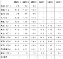
- Table showing experimental results Sectional drawing of the principal part of the illuminating device of 18th Embodiment of this invention.
- the chip-type LED element 10 is used, but a bullet-type or other types of LED elements can also be used.
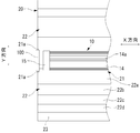
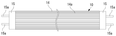
- the heat sink 14 is made of a metal material such as aluminum, for example, and has a plurality of heat radiation fins 14 a extending in the longitudinal direction of the light source 10 at positions that constitute the outer peripheral surface of the light source 10.
- the light source 10 is attached to the indoor ceiling by inserting the terminal 15a of each base 15 into a socket 100 provided on the indoor ceiling. Further, when the light source 10 is attached to the ceiling in the room, each LED element 11 of the light source 10 is attached so as to face directly above.
- each LED element 11 of the light source 10 faces directly above, and the heat sink 14 of the light source 10 is positioned below the light source 10.
- the socket 100 an existing socket for attaching a fluorescent lamp can be used as it is, and the base 15 or the substrate 13 is provided with a circuit for converting an alternating current into a direct current suitable for each LED 11.
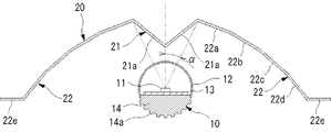
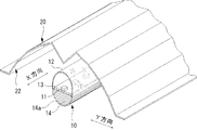
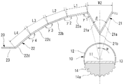
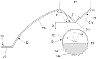
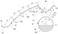
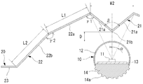
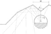
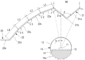
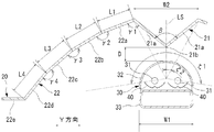
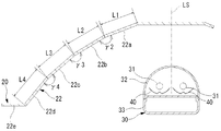
- the reflection plate 20 is formed by bending a metal plate such as aluminum and has a first reflection surface 21 and a pair of second reflection surfaces 22.
- each of the reflecting surfaces 21 and 22 is formed to have a rough surface or have irregularities so that the center line average roughness is 0.5 ⁇ m or more.
- the surface of the aluminum plate constituting each of the reflecting surfaces 21 and 22 is subjected to rough surface processing and anodic oxide coating processing such as shot blasting so that the center line average roughness is 0.5 ⁇ m or more. .
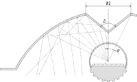
- the pair of surfaces 21a may be disposed so as to receive light in the predetermined light irradiation angle range ⁇ in the Y direction.
- the width dimension W2 of the first reflecting surface 21 in the Y direction is 36 mm.
- the plurality of LED elements 11 are arranged in a line, and the center of the light irradiation range in the Y direction of the light source 10 coincides with the optical axis of the LED element 11.
- the ridge line 21 b of the first reflecting surface 21 is arranged at the center of the light irradiation range in the Y direction of the light source 10.
- the distance D between the ridge line 21b of the first reflecting surface 21 and the light transmitting cover 12 of the light source 10 is about 1/3 of the width dimension W2 of the first reflecting surface W2.
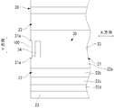
- Each second reflecting surface 22 is provided on both outer sides in the Y direction with respect to the first reflecting surface 21, and the first reflecting surface 21 is arranged in a space between the pair of second reflecting surfaces 22.
- Each of the second reflecting surfaces 22 includes a first surface 22a that constitutes a portion closest to the first reflecting surface 21, a second surface 22b that constitutes a portion next to the first reflecting surface 21, and Next, it has the 3rd surface 22c which comprises the part close
- Each of the first to fourth surfaces 22a to 22d is a flat surface and extends in the X direction.
- a flange portion 23 is provided at the outer end of the fourth surface 22d, and the flange portion 23 is provided for mounting to the indoor ceiling.
- the first surface 22a forms an angle ⁇ 1 ( ⁇ 1 is 120 ° in the present embodiment) with the surface 21a of the first reflecting surface 21, and the second surface 22b forms an angle ⁇ 2 with the first surface 22a (in the present embodiment).
- ⁇ 2 forms 170 °
- the third surface 22c forms an angle ⁇ 3 with the second surface 22b (in this embodiment, ⁇ 3 is 170 °)
- the fourth surface 22d forms an angle ⁇ 4 with the third surface 22c.
- ⁇ 4 is 170 °.
- the width dimensions L1 to L4 of the first to fourth surfaces 22a to 22d are each 19 mm.
- the first reflection surface 21 is disposed in the space between, the light reflected by the first reflection surface 21 is further reflected by the second reflection surface 22, and the light from the light source 10 is reflected on the first reflection surface. Light that is not irradiated is reflected by the second reflecting surface.
- each LED element 11 is arranged so that the optical axis faces directly above, the first reflecting surface 21 is arranged above the LED element 11, and the ridge line 21b of the first reflecting surface 21 is convex downward. It has become.
- the first reflecting surface 21 is disposed in the space between the pair of second reflecting surfaces 22, and the light reflected by the first reflecting surface 21 is further reflected by the second reflecting surface 22, and each LED Of the light from the element 11, the light not irradiated on the first reflecting surface 21 is reflected by the second reflecting surface, and the light reflected by the second reflecting surface 22 is irradiated toward the irradiation position such as the indoor floor. Is done.
- each LED element 11 of the light source 10 faces upward, and a heat sink 14 for preventing a temperature rise of each LED element 11 in the light source 10 is disposed below the LED element 11. ing. That is, in the light source 10, each LED element 11 is disposed on the first reflecting surface 21 side of the reflecting plate 20, and the heat sink 14 is disposed on the side away from the first reflecting surface 21. It becomes easy to hit air, and heat can be efficiently dissipated.
- each of the reflecting surfaces 21 and 22 is formed to have a rough surface or an unevenness by embossing or the like so that the center line average roughness is 0.5 ⁇ m or more.
- the light source 10 is a set of LED elements 11 that are point light sources, and each LED element 11 has a strong directivity of light, but the light from each LED element 11 is diffused by the reflecting surfaces 21 and 22. Is done.
- the strong light around the optical axis of each LED element 11 is reflected by both the first reflecting surface 21 and the second reflecting surface 22 and irradiated to the irradiation position, the unevenness of the light at the irradiation position is reduced. Is very advantageous.
- each of the reflecting surfaces 21 and 22 is mirror-finished and the center line average roughness is about 0.1 ⁇ m, when the light from each LED element 11 is reflected by each of the reflecting surfaces 21 and 22, Not a little light from each LED element 11 is diffused by each reflecting surface 21, 22. For this reason, compared with the case where the light of each LED element 11 is directly irradiated to irradiation positions, such as a floor, the light from each LED element 11 is spread
- the pair of surfaces 21 a of the first reflecting surface 21 of the present embodiment has a predetermined light irradiation angle range ⁇ with respect to the optical axis of each LED 11 of the light source 10 (in this embodiment, ⁇ is 15).
- ⁇ is 15
- ⁇ is 60 °
- the width dimension W2 of the first reflecting surface 21 in the Y direction is 23.5 mm
- the distance D between the ridge line 21b of the first reflecting surface 21 and the light transmitting cover 12 of the light source 10 is the width dimension of the light transmitting cover. It is about 1/3 of W1.
- the first surface 22a of the second reflecting surface 22 forms an angle ⁇ 1 ( ⁇ 1 is 110 ° in the present embodiment) with the surface 21a of the first reflecting surface 21, and the second surface 22b is the first surface 22a.
- the angle ⁇ 2 ( ⁇ 2 is 170 ° in the present embodiment)
- the third surface 22c forms an angle ⁇ 3 ( ⁇ 3 is 170 ° in the present embodiment) with the second surface 22b
- the fourth surface 22d is the third surface.
- an angle ⁇ 4 in this embodiment, ⁇ 4 is 170 °).
- the width dimensions L1 to L4 of the first to fourth surfaces 22a to 22d are each 19 mm.
- the illuminating device of this embodiment also has the same effect as the illuminating device of 1st Embodiment.
- a lighting device according to a third embodiment of the present invention will be described with reference to FIGS.
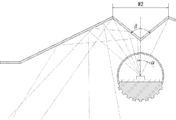
- the angle ⁇ and the width dimension W2 of the first reflecting surface 21 of the reflecting plate 20 are changed in the first embodiment, and other configurations are the same as those in the first embodiment.
- the pair of surfaces 21 a of the first reflecting surface 21 of the present embodiment has a predetermined light irradiation angle range ⁇ (in this embodiment, ⁇ is 30) with respect to the optical axis of each LED 11 of the light source 10.
- ⁇ is 30
- ⁇ is 120 °
- the width dimension W2 of the first reflecting surface 21 in the Y direction is 40.5 mm
- the distance D between the ridge line 21b of the first reflecting surface 21 and the light transmitting cover 12 of the light source 10 is the width dimension of the light transmitting cover. It is about 1/3 of W1.
- the first surface 22a of the second reflecting surface 22 forms an angle ⁇ 1 ( ⁇ 1 is 120 ° in the present embodiment) with the surface 21a of the first reflecting surface 21, and the second surface 22b is the first surface 22a.
- the angle ⁇ 2 ( ⁇ 2 is 170 ° in the present embodiment)
- the third surface 22c forms an angle ⁇ 3 ( ⁇ 3 is 170 ° in the present embodiment) with the second surface 22b
- the fourth surface 22d is the third surface.
- an angle ⁇ 4 in this embodiment, ⁇ 4 is 170 °).
- the width dimensions L1 to L4 of the first to fourth surfaces 22a to 22d are each 19 mm.
- the illuminating device of this embodiment also has the same effect as the illuminating device of 1st Embodiment.
- a lighting device according to a fourth embodiment of the present invention will be described with reference to FIGS.
- the present embodiment is obtained by changing the specification of the second reflecting surface 22 of the reflecting plate 20 in the first embodiment, and the other configuration is the same as that of the first embodiment.
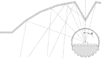
- each LED element 11 In the illumination device configured as described above, light in a light irradiation angle range of 25 ° with respect to the optical axis of each LED element 11 is reflected by the first reflecting surface 21, and most of the reflected light is As shown in FIG. 14, it proceeds toward the outside so as to form an angle (an angle of approximately 70 ° or more) corresponding to the inclination angle of the first reflecting surface 21 with respect to the optical axis of each LED element 11. .
- the illuminating device of this embodiment also has the same effect as the illuminating device of 1st Embodiment.
- a lighting device according to a fifth embodiment of the present invention will be described with reference to FIGS.
- the specification of the first reflecting surface 21 and the angle ⁇ 1 of the second reflecting surface 22 of the reflecting plate 20 are changed in the first embodiment, and other configurations are the same as those in the first embodiment. is there.
- the pair of surfaces 21a of the first reflecting surface 21 of the present embodiment has a predetermined light irradiation angle range ⁇ with respect to the optical axis of each LED 11 of the light source 10 ( ⁇ is 23 in this embodiment).
- ⁇ is 23 in this embodiment.
- ⁇ is 102 °
- Each surface 21a has a width direction inner side surface IS extending in the X direction, and a width direction outer surface OS extending outside in the Y direction with respect to the width direction inner side surface IS and extending in the X direction.
- the ridge line 21b is formed at a portion where the inner surfaces IS in the width direction intersect.
- the width direction outer side surface OS forms a predetermined angle ⁇ ( ⁇ in this embodiment is 190 °) with the width direction inner side surface IS.
- the width dimension W2 in the Y direction of the first reflective surface 21 is 31 mm, and the distance D between the ridge line 21b of the first reflective surface 21 and the translucent cover 12 of the light source 10 is the width dimension W1 of the translucent cover. About 1/3.
- the first surface 22a of the second reflecting surface 22 forms an angle ⁇ 1 ( ⁇ 1 is 110 ° in this embodiment) with the surface 21a of the first reflecting surface 21.
- the illuminating device of this embodiment also has the same effect as the illuminating device of 1st Embodiment.
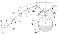
- a lighting device according to a sixth embodiment of the present invention will be described with reference to FIGS.
- the present embodiment is obtained by changing the specification of the second reflecting surface 22 of the reflecting plate 20 in the first embodiment, and the other configuration is the same as that of the first embodiment.
- Each second reflecting surface 22 of the present embodiment is provided on both outer sides in the Y direction with respect to the first reflecting surface 21, and the first reflecting surface 21 is in a space between the pair of second reflecting surfaces 22. Is arranged.
- Each of the second reflecting surfaces 22 includes a first surface 22a that constitutes a portion closest to the first reflecting surface 21, and a second surface 22b that constitutes a portion that is next closest to the first reflecting surface 21.
- Each of the first and second surfaces 22a and 22b is a flat surface and extends in the X direction.
- the first surface 22a forms an angle ⁇ 1 (in this embodiment, ⁇ 1 is 115 °) with the surface 21a of the first reflecting surface 21, and the second surface 22b forms an angle ⁇ 2 with the first surface 22a (in this embodiment).
- ⁇ 2 is 160 °).
- the width dimensions L1 and L2 of the first and second surfaces 22a and 22b are 38 mm, respectively.
- each LED element 11 In the illumination device configured as described above, light in a light irradiation angle range of 25 ° with respect to the optical axis of each LED element 11 is reflected by the first reflecting surface 21, and most of the reflected light is As shown in FIG. 18, it proceeds toward the outside so as to form an angle (approximately 70 ° or more) corresponding to the inclination angle of the first reflecting surface 21 with respect to the optical axis of each LED element 11. .
- the illuminating device of this embodiment also has the same effect as the illuminating device of 1st Embodiment.
- a lighting device according to a seventh embodiment of the present invention will be described with reference to FIGS.
- the present embodiment is obtained by changing the specification of the second reflecting surface 22 of the reflecting plate 20 in the first embodiment, and the other configuration is the same as that of the first embodiment.
- Each second reflecting surface 22 of the present embodiment is provided on both outer sides in the Y direction with respect to the first reflecting surface 21, and the first reflecting surface 21 is in a space between the pair of second reflecting surfaces 22. Is arranged.
- Each second reflecting surface 22 has a first surface 22a that constitutes a portion closest to the first reflecting surface 21, and the first and second surfaces 22a are flat and extend in the X direction. Yes.
- the first surface 22a forms an angle ⁇ 1 with the surface 21a of the first reflecting surface 21 ( ⁇ 1 is 115 ° in the present embodiment).
- the width dimension L1 of the first surface 22a is 70 mm.
- the illumination device configured as described above, light in a light irradiation angle range of 25 ° with respect to the optical axis of each LED element 11 is reflected by the first reflecting surface 21, and most of the reflected light is As shown in FIG. 20, it proceeds toward the outside so as to make an angle corresponding to the inclination angle of the first reflecting surface 21 with respect to the optical axis of each LED element 11 (an angle of about 70 ° or more). .
- the illuminating device of this embodiment also has the same effect as the illuminating device of 1st Embodiment.
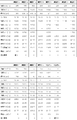
- FIG. 21 shows the experimental results.
- the experimental results show that the lighting devices of the first to seventh embodiments are manufactured, and other lighting devices in which the angle ⁇ , the width dimension W2, and the distance D are changed in the first and second embodiments are manufactured. This is an evaluation of illuminance and illuminance unevenness on the floor as an irradiation position.
- Experimental examples 1 to 7 in FIG. 21 correspond to the first to seventh embodiments, respectively, and experimental example 8 has a width dimension W2 of 29 mm and an angle ⁇ of 20 ° in the first embodiment. Is a width dimension W2 of 21.5 mm and an angle ⁇ of 15 ° in the first embodiment, and Experimental Example 10 is a width dimension W2 of 14.5 mm and an angle ⁇ of 10 ° in the first embodiment.
- the width dimension W2 is 7.2 mm and the angle ⁇ is 5 ° in the first embodiment.
- Experimental Example 12 in FIG. 21 is obtained by making the distance D equal to the width dimension W2 in the second embodiment.
- Comparative Example 1 in FIG. 21 is such that, in the first embodiment, the optical axis of each LED element 10 faces directly below, and most of the light from the light source 10 is directly irradiated onto the floor.
- Example 2 as shown in FIG. 23, a flat reflecting surface is provided instead of the first reflecting surface 21.
- the Experimental Examples 1, 8, 9, 10, and 11 in which the angle ⁇ is 102 ° have less illuminance variation.
- the angle ⁇ is more preferably in the range of 70 ° or more and 115 ° or less in order to reduce the unevenness of the light at the irradiation position, and the range of 90 ° or more and 110 ° or less is the unevenness of the light in the irradiation position. It is considered to be more preferable in terms of reduction.
- each second reflecting surface 22 was composed of a plurality of planes or a single plane. This is because light is emitted radially from each LED element 11 and is reflected by the first reflecting surface 21 which is a flat surface. Therefore, when the second reflecting surface 22 is a concave curved surface, each LED element 11. One reason is that the light from the first reflecting surface 21 tends to be collected by the second reflecting surface 22. In Experimental Example 4, since the average illuminance is higher than that of Comparative Example 1 and the illuminance variation is small, the same effect as in the first embodiment is recognized.
- the angle ⁇ 1 formed between each surface 21a of the first reflecting surface 21 and the vicinity of the first reflecting surface 21 in each second reflecting surface 22 is 110 ° to 130 °. In this range, the above-described effects are confirmed.
- This angle ⁇ 1 can be appropriately changed according to the light source 10, the first reflecting surface 21, and the irradiation range. From the results of Experimental Examples 1 to 12, when the present lighting device is provided on the ceiling for room lighting, the angle ⁇ 1 ⁇ 1 is preferably 100 ° or more and 140 ° or less, and more preferably 110 ° or more and 130 ° or less.
- the second reflecting surfaces 22 are arranged side by side in the Y direction and are continuous with each other at a predetermined angle ⁇ 2 to ⁇ 4. It has been confirmed that the construction of a plurality of planes is advantageous in reducing the unevenness of light at the irradiation position.
- the angles ⁇ 2 to ⁇ 4 are 160 ° to 170 °, and the above-described effects are confirmed in this range.
- the angle ⁇ 1 can be appropriately changed according to the light source 10, the first reflecting surface 21, and the irradiation range. From the results of Experimental Examples 1 to 3, 5, 6, and 8 to 12, the angle ⁇ 1 is 155 ° or more. It is preferable that it is preferably 160 ° or more and 175 ° or less.
- the ridge line 21b is shown in a linear shape.
- the width dimension W3 is preferably 1/5 or less of the width dimension W2, more preferably 1/10 or less, and even more preferably 1/20 or less. That is, the smaller the width dimension W3, the better.
- the ridge line 21b is a flat surface, but it may be a convex curved surface or a concave curved surface.
- the ridgeline 21b and the optical axis of each LED element 11 coincide with each other.
- the ridgeline 21b and the optical axis of each LED element 11 can be shifted in the Y direction. Even in this case, since the light of the predetermined irradiation angle range ⁇ is reflected by the first reflecting surface 21 with respect to the optical axis of each LED element 11, if the angle ⁇ is in accordance with the experimental result of FIG. The same effects as described above are achieved. Further, as shown in FIG.
- the second reflecting surface 22 on the side where the optical axis of each LED element 11 is arranged is arranged. It is also possible to increase the amount of reflected light.
- the light source 10 in which a plurality of LED elements 11 are arranged in a line in the X direction is shown.
- FIG. 26 it is also possible to arrange a plurality of LED elements 11 in a plurality of rows in the X direction.
- the first reflecting surface 21 receives light in a predetermined irradiation angle range ⁇ with respect to the optical axis of the LED elements 11 in each row, and the angle ⁇ is If it is along the experimental result of FIG. 21, the effect similar to the above can be show
- the first reflecting surface 21 receives light in a predetermined irradiation angle range ⁇ with respect to the optical axis of the LED elements 11 in at least one row of each row, and the angle ⁇ is as shown in FIG. As long as it is in accordance with the experimental results, the same effects as described above can be obtained.
- the light source 10 may be configured such that the optical axes of the LED elements 11 in each row are directed in different directions. Even in this case, as long as the light in the predetermined light irradiation angle range ⁇ 2 is received by the pair of surfaces of the first reflecting surface with respect to the center of the light irradiation angle range ⁇ 1 of the light source 10, the same as described above. Has the effect of.
- the range of the angle ⁇ 2 is set to the same setting as the angle ⁇ in each of the above-described embodiments, so that the same effect as that in each of the above-described embodiments is achieved.
- the reference of the angles ⁇ 1 and ⁇ 2 can be, for example, the center position CP of each row as shown in FIG.
- the LED elements 11 in the light source 10 are arranged in a straight line.
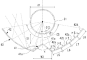
- the LED elements 11 are arranged in the circumferential direction in the light source 10.
- the X direction is a circumferential direction
- the Y direction is a radial direction of the circumference.
- the light source 10 has a ring shape
- the reflection plate 20 also has a ring shape along the light source 10. In this case, the same effects as those of the above embodiments can be obtained.
- each surface 21a of the first reflecting surface 21 is completely flat.
- the radius of curvature is at least twice the width dimension W2, or the depth dimension.
- each surface 21a is assumed to be a flat surface. The reason for this is that even when a curved surface having a slight curvature is used as described above, the angle ⁇ and the like are set in the same manner as in each of the above embodiments, so that the same effect as that in each of the above embodiments can be achieved. Because.
- each of the surfaces 22a to 22d of the second reflecting surface 22 is also formed by a curved surface having a radius of curvature of at least twice the width dimension W2 or a depth dimension DP or a projecting dimension of 1 mm or less. It is assumed that 22a to 22d are flat surfaces.
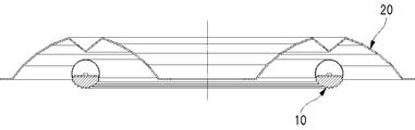
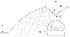
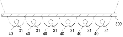
- the extending direction of the fluorescent tube 31 is the X direction, is orthogonal to the extending direction of the fluorescent tube 31, and the optical axis plane LS of the fluorescent lamp 30 described below.
- a direction orthogonal to the Y direction is taken as a Y direction.
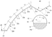
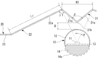
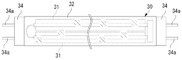
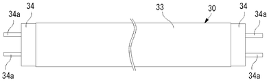
- This illumination device includes a fluorescent lamp 30 and a reflector 20 as shown in FIGS.
- the fluorescent lamp 30 is configured to irradiate light in a predetermined light irradiation angle range ⁇ 1 in a direction (Y direction) orthogonal to the extending direction of the fluorescent tube 31.
- the central surface (surface extending in the X direction) of the light irradiation angle range ⁇ 1 is referred to as an optical axis surface LS of the fluorescent lamp 30.
- the fluorescent lamp 30 is mounted so that the optical axis surface LS faces directly upward when mounted on an indoor ceiling.
- fluorescent lamp 30 it is possible to use, for example, cold cathode tube lamps disclosed in Japanese Patent Application Laid-Open Nos. 2010-251261, 2010-244835, 2010-211961, and the like.
- a plurality of (two in this embodiment) fluorescent tubes 31 composed of cold cathode tubes (CCFL tubes) extending in a predetermined direction (X direction) and extending along each fluorescent tube 31.
- CCFL tubes cold cathode tubes
- Each in-lamp reflector 40 is attached to the case 33 by a fixture (not shown), and each fluorescent tube 31 is also attached to the case 33 by a fixture (not shown).
- Each fluorescent tube 31 is disposed between the in-lamp reflector 40 and the translucent cover 32.
- the width dimension W1 of the translucent cover 32 is 28 mm, but it is also possible to use a translucent cover 32 having a width dimension W1 other than that.
- the fluorescent lamp 30 is of a type in which the light diffusion of each fluorescent tube 31 by the translucent cover 32 is small, but a type in which the light diffusion of each fluorescent tube 31 by the translucent cover 33 is large can also be used. It is.
- a cold cathode tube is used as the fluorescent tube 31, but other fluorescent tubes such as a T4 fluorescent tube and a T5 fluorescent tube can be used.
- the two fluorescent tubes 31 are separately formed. However, the two fluorescent tubes 31 are continuous at one end in the length direction with, for example, a U-shaped fluorescent tube. It is also possible to form it. Even in this case, in this embodiment, it is assumed that the two fluorescent tubes 31 extend in the X direction.
- Each fluorescent tube 31 has a diameter d1 of several millimeters (5 mm in the present embodiment), and is arranged so as to be substantially parallel to each other.
- the case 33 is a cylindrical member made of a metal material such as aluminum and extending in the extending direction of each fluorescent tube 31, and includes an inverter or a PFC (Power Factor Controller, not shown) for supplying power to each fluorescent tube 31 inside. Z).
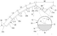
- Each in-lamp reflecting plate 40 is formed by bending a metal plate such as aluminum and has a first reflecting surface 41 and a second reflecting surface 42.
- each of the reflecting surfaces 41 and 42 is formed to have a rough surface or have irregularities so that the center line average roughness is 0.5 ⁇ m or more.
- the surface of the aluminum plate constituting each of the reflection surfaces 41 and 42 is subjected to rough surface treatment and anodizing treatment by shot blasting or the like so that the center line average roughness is 0.5 ⁇ m or more.
- a plurality of small recesses are formed on the surface of the aluminum plate constituting each of the reflecting surfaces 41 and 42 by embossing or the like, and in order to improve the reflectance on the aluminum surface, glass or plastic
- the translucent material is coated with PVD or the like.
- the first reflecting surface 41 is composed of a pair of surfaces 41a extending in the X direction.
- Each surface 41a is a flat surface, and a convex ridge 41b toward the fluorescent lamp 30 is formed at a portion where the pair of surfaces 41a intersect.
- Each fluorescent tube 31 irradiates light within a light irradiation angle range of 360 ° in a direction orthogonal to the extending direction, and each of the in-lamp reflectors 40 is out of the light irradiated from the corresponding fluorescent tube 31. It receives light in a predetermined light irradiation angle range ⁇ 1.
- the first reflecting surface 41 has an angle ⁇ 2 (in this embodiment, ⁇ 2 is 17 °) with respect to the central surface CS of the predetermined light irradiation angle range ⁇ 1 that is irradiated from the fluorescent tube 31 to each in-lamp reflecting plate 40. )
- the surfaces 41a of the first reflecting surface 41 form an angle ⁇ ( ⁇ is 100 ° in the present embodiment) in the vicinity of the ridge line 41b.
- the width dimension W3 in the Y direction of the first reflecting surface 41 is 3.5 mm
- the distance D1 between the ridge line 41b of the first reflecting surface 41 and the fluorescent tube 31 is the diameter of the fluorescent tube 31. It is about 1/2 of d1.
- Each second reflecting surface 42 is provided on both outer sides in the Y direction with respect to the first reflecting surface 41, and the first reflecting surface 41 is arranged in a space between the pair of second reflecting surfaces 42.
- Each of the second reflecting surfaces 42 includes a first surface 42a constituting a portion closest to the first reflecting surface 41, and a second surface 42b constituting a portion next to the first reflecting surface 41, Next, it has the 3rd surface 42c which comprises the part close
- Each of the first to fourth surfaces 42a to 42d is a flat surface and extends in the X direction.
- the first surface 42a forms an angle ⁇ 5 ( ⁇ 5 is 120 ° in this embodiment) with the surface 41a of the first reflecting surface 41
- the second surface 42b forms an angle ⁇ 6 (in this embodiment) with the first surface 42a.
- ⁇ 6 is 170 °
- the third surface 42c is at an angle ⁇ 7 with the second surface 42b (in this embodiment, ⁇ 7 is 170 °)
- the fourth surface 42d is at an angle ⁇ 8 (with ⁇ 8 ( In this embodiment, ⁇ 8 is 170 °.
- the width dimensions L5 to L8 of the first to fourth surfaces 42a to 42d are 2 mm, respectively.
- the fluorescent lamp 30 is attached to the indoor ceiling by inserting the terminal 34a of each base 34 into the socket 100 provided on the indoor ceiling.
- the socket 100 an existing socket for attaching a fluorescent lamp can be used as it is.
- the reflector 20 is the same as that of the first embodiment, and is attached to the indoor ceiling as in the first embodiment. Specifically, when the fluorescent lamp 30 is attached to the socket 100, the reflector 20 is attached to the ceiling of the room so as to be positioned above the fluorescent lamp 30.
- the pair of surfaces 21a of the first reflecting surface 21 of the reflecting plate 20 has a predetermined light irradiation angle range ⁇ 2 ( ⁇ 2 in this embodiment) with respect to the optical axis surface LS of the fluorescent lamp 30.
- ⁇ 2 in this embodiment
- the distance D between the ridge line 21b of the first reflecting surface 21 and the translucent cover 32 of the fluorescent lamp 30 is about 1/3 of the width dimension W2 of the translucent cover 32.
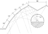
- the light advances toward the outside so as to form an angle corresponding to the inclination angle of the first reflecting surface 21 with respect to the optical axis surface LS of the fluorescent lamp 30 (an angle of about 70 ° or more). Moreover, it has a pair of 2nd reflective surface 22 provided in the both outer sides of the direction which cross
- the first reflecting surface 21 is disposed in the space between the two. For this reason, the light reflected by the first reflecting surface 21 is reflected by the second reflecting surface 22, while the light directly irradiated from the fluorescent lamp 30 is also reflected by the second reflecting surface 22.
- the fluorescent lamp 30 is disposed so that the optical axis surface LS faces directly upward, the first reflecting surface 21 is disposed above the fluorescent lamp 30, and the first reflecting surface 21 is disposed.
- the ridge line 21b is convex downward.
- the first reflecting surface 21 is disposed in the space between the pair of second reflecting surfaces 22. For this reason, the light reflected by the first reflecting surface 21 is further reflected by the second reflecting surface 22, while the light directly irradiated from the fluorescent lamp 30 is also reflected by the second reflecting surface 22, and the second The light reflected by the reflecting surface 22 is irradiated toward an irradiation position such as an indoor floor. Therefore, according to this embodiment, the light from the fluorescent lamp 30 can be efficiently irradiated to the irradiation position such as the floor.
- each of the reflecting surfaces 21 and 22 is formed to have a rough surface or an unevenness by embossing or the like so that the center line average roughness is 0.5 ⁇ m or more.
- the fluorescent lamp 30 is composed of two fluorescent tubes 31, and light is emitted from the two line light sources, but the light from each fluorescent tube 31 is diffused by the reflecting surfaces 21 and 22. .
- the unevenness of the light at the irradiation position is reduced. Is very advantageous.
- the reflecting surfaces 21 and 22 are mirror-finished, for example, and the center line average roughness is about 0.1 ⁇ m, when the light from the fluorescent lamp 30 is reflected by the reflecting surfaces 21 and 22, Not a little light from the lamp 30 is diffused by the reflecting surfaces 21 and 22. For this reason, compared with the case where the light of the fluorescent lamp 30 is directly irradiated to the irradiation position such as the floor, the light from the fluorescent lamp 30 is diffused, and uneven illuminance at the irradiation position can be reduced.
- FIG. 38 shows the experimental results, and shows the results of the same evaluation performed by the same method as in FIG.
- the lighting device of the eighth to fourteenth embodiments was manufactured, and another lighting device having the width dimension W2 and the distance D changed in the eighth embodiment was manufactured.
- the illumination device of the ninth embodiment is obtained by changing the reflection plate 20 to the reflection plate 20 of the second embodiment (see FIGS. 9 and 10) in the eighth embodiment, and the illumination device of the tenth embodiment In the eighth embodiment, the reflection plate 20 is changed to the reflection plate 20 of the third embodiment (see FIGS. 11 and 12), and the illuminating device of the eleventh embodiment replaces the reflection plate 20 in the eighth embodiment.
- the illuminating device of the twelfth embodiment is changed to the reflector 20 of the fourth embodiment (see FIGS. 13 and 14), and the illuminating device of the twelfth embodiment replaces the reflector 20 in the fifth embodiment (FIGS. 15 and 15). 16), the illuminating device of the thirteenth embodiment is changed from the reflecting plate 20 to the reflecting plate 20 of the sixth embodiment (see FIGS. 17 and 18) in the eighth embodiment. 14th implementation Lighting device state is obtained by changing the reflecting plate 20 to the reflection plate 20 of the seventh embodiment (see FIGS. 19 and 20) in the eighth embodiment.
- the optical axis surface LS of the fluorescent lamp 30 faces directly above, and the position of the optical axis surface LS is the first reflecting surface of the reflecting plate 20.
- the distance D between the ridge line 21b of the first reflecting surface 21 of the reflector 20 and the fluorescent tube 31 is about 1/3 of the width W2.
- Experimental examples 13 to 19 in FIG. 38 correspond to the eighth to fourteenth embodiments, respectively, and experimental example 20 is an experiment in which the width dimension W2 is 25 mm and the angle ⁇ 2 is 20 ° in the eighth embodiment.
- Example 21 is an example in which the width dimension W2 is 18 mm and the angle ⁇ 2 is 15 ° in the eighth embodiment
- Experimental Example 22 is an example in which the width dimension W2 is 12 mm and the angle ⁇ 2 is 10 ° in the eighth embodiment.
- the width W2 is 6 mm and the angle ⁇ 2 is 5 ° in the eighth embodiment.
- Experimental Example 24 in FIG. 38 is the distance D made equal to the width dimension W2 in the ninth embodiment.
- Comparative Example 3 in FIG. 38 is such that in the eighth embodiment, the optical axis surface LS of the fluorescent lamp 30 faces directly below, and most of the light from the fluorescent lamp 30 is directly irradiated onto the floor.
- Comparative Example 4 as shown in FIG. 39, a flat reflecting surface is provided in place of the first reflecting surface 21.
- each second reflecting surface 22 was composed of a plurality of planes or a single plane. This is considered to be one of the reasons that the light from the fluorescent lamp 30 tends to be collected by the second reflecting surface 22 when the second reflecting surface 22 is a concave curved surface.
- the average illuminance is higher and the illuminance variation is smaller than that of Comparative Example 4 in Experimental Example 16, the same effects as in the eighth embodiment are recognized.
- an angle ⁇ 1 formed between each surface 21a of the first reflecting surface 21 and the vicinity of the first reflecting surface 21 in each second reflecting surface 22 is 110 ° to 130 °. In this range, the above-described effects are confirmed.
- the angle ⁇ 1 can be appropriately changed according to the fluorescent lamp 30, the first reflecting surface 21, and the irradiation range. However, when the lighting device is provided for indoor lighting, the angle ⁇ 1 is 100 ° or more and 140 ° or less. It is preferable that the angle is 110 ° or more and 130 ° or less.
- the second reflecting surfaces 22 are arranged side by side in the Y direction and are continuous with each other at a predetermined angle ⁇ 2 to ⁇ 4. It has been confirmed that the construction of a plurality of planes is advantageous in reducing the unevenness of light at the irradiation position.
- the angles ⁇ 2 to ⁇ 4 are 160 ° to 170 °, and the above-described effects are confirmed in this range.
- the angle ⁇ 1 can be appropriately changed according to the tendency lamp 30, the first reflecting surface 21, and the irradiation range. From the results of Experimental Examples 13 to 15, 17, 18, and 20 to 24, the angle ⁇ 1 is 155 ° or more. It is preferable that it is 160 ° or more and 175 ° or less.
- the ridgeline 21b is shown in a linear shape, but the ridgeline 21b shown in FIG. 24 is used even in the case where the reflecting plate 21 in which the ridgeline 21b appears in a planar shape having a width dimension W3 is used.
- the width dimension W3 distance between the one surface 21a and the other surface 21a
- the width dimension W3 is preferably 1/5 or less of the width dimension W2, more preferably 1/10 or less, and even more preferably 1/20 or less. That is, the smaller the width dimension W3, the better.
- the ridge line 21b is a flat surface, but it may be a convex curved surface or a concave curved surface.
- the ridgeline 21b and the optical axis plane LS of the tendency lamp 30 are shown to coincide with each other.
- the ridgeline 21b and the optical axis surface LS of the fluorescent lamp 30 can be shifted in the Y direction. Even in this case, since the light in the predetermined irradiation angle range ⁇ 2 is reflected by the first reflecting surface 21 with respect to the optical axis surface LS of the fluorescent lamp 30, if the angle ⁇ 2 is in accordance with the experimental result of FIG. The same effects as described above are obtained. Also, as shown in FIG.
- the second reflecting surface on the side where the optical axis surface LS of the fluorescent lamp 30 is arranged by positively shifting the ridge line 21b and the optical axis surface LS of the fluorescent lamp 30 in the Y direction. It is also possible to increase the amount of reflection of 22 light.
- the one using the fluorescent lamp 30 in which the plurality of fluorescent tubes 31 are arranged in the Y direction is shown. Play.
- the fluorescent lamps 31 of the fluorescent lamp 30 are shown as being straight, but as shown in FIG. 42, the fluorescent lamp 30 is ring-shaped and each fluorescent lamp 31 is Even in the case of a ring shape, the same configuration as in the eighth to fourteenth embodiments can be adopted.
- the X direction is a circumferential direction
- the Y method is a radial direction
- the reflector 20 has a ring shape. Even in this case, the same effects as those of the eighth to fourteenth embodiments can be obtained.
- the surfaces 21a of the first reflecting surface 21 are completely flat.
- the radius of curvature is 2 with a width dimension W2.
- each surface 21a is constituted by a curved surface having a depth of DP or more, or a depth dimension DP or a protrusion dimension of 1 mm or less, each surface 21a is assumed to be a flat surface. The reason for this is that even when a curved surface having a slight curvature is used as described above, the angle ⁇ and the like are set in the same manner as in each of the above embodiments, so that the same effect as that in each of the above embodiments can be achieved. Because.
- each of the surfaces 22a to 22d of the second reflecting surface 22 is also formed by a curved surface having a radius of curvature of at least twice the width dimension W2 or a depth dimension DP or a projecting dimension of 1 mm or less. It is assumed that 22a to 22d are flat surfaces.
- each reflecting plate 40 of the fluorescent lamp 30 has the first reflecting surface 41 and the second reflecting surface 42.
- each reflector 40 of the fluorescent lamp 30 can be replaced with a reflector 50 (fifteenth embodiment).
- the reflection plate 50 has a shape obtained by cutting a part of the cylinder in the circumferential direction.
- the two reflectors 40 of the fluorescent lamp 30 can be replaced with one reflector 60 (the sixteenth embodiment).
- the fluorescent lamp 30 can be replaced by one fluorescent tube 70 (a seventeenth embodiment).
- the fluorescent tube 70 it is possible to use a cold cathode tube as the fluorescent tube 70, and it is also possible to use a T4 fluorescent tube, a T5 fluorescent tube or another fluorescent tube which is not a cold cathode tube.
- a normal fluorescent tube is used, and the fluorescent tube 70 has a width (diameter) W1 of 28 mm.
- the fluorescent tube 70 irradiates light in a light irradiation angle range of 360 ° in a direction orthogonal to the extending direction.
- light in a predetermined light irradiation angle range ⁇ 2 (in the present embodiment, ⁇ 2 is 28 °) among the light emitted from the fluorescent tube 70 is received by the first reflecting surface 21 of the reflecting plate 20. Yes.
- FIG. 46 shows the experimental results, and shows the results of evaluation by the same method as in FIGS. 21 and 38.
- the illumination devices of the fifteenth to seventeenth embodiments were manufactured, and the illuminance and the unevenness of the illuminance on the floor as the irradiation position were evaluated.
- Experimental examples 25 to 27 in FIG. 46 correspond to the fifteenth to seventeenth embodiments, respectively.
- a reflective surface which is a plane is provided in place of the first reflective surface 21 as in the case of FIG. It is.
- the diameter d2 of the fluorescent tube 70, the distance between the fluorescent tube 70 and the ridge line 21b, the width W2 and the angle ⁇ of the first reflecting surface 21, etc. are the specifications and irradiation position of the fluorescent tube 70.
- the angle ⁇ 2 the angle ⁇ , the distance D, and the angles ⁇ 1 to 4 are in accordance with the experimental results of FIG. 38, the same as in the eighth to fourteenth embodiments.
- the light from the fluorescent tube 70 can be effectively irradiated to the irradiation position.
- the optical axis LS of the fluorescent lamp 30 faces directly below, and most of the light from the fluorescent lamp 30 is directly irradiated onto the floor. Even in this case, the light from each fluorescent tube 31 can be used effectively by the lamp reflector 40 as described above. For this reason, the fluorescent lamp 30 of the eighth embodiment can be used alone as a lighting device.
- the diameter d 1 of the fluorescent tube 31, the distance D 1 between the fluorescent tube 31 and the ridge line 41 b, the width W 3 of the first reflecting surface 41, the angle ⁇ , and the like are the specifications of the fluorescent tube 31 and the fluorescent tube 31.
- the angle ⁇ 2, the angle ⁇ , the distance D1, and the angles ⁇ 5 to 7 of the reflecting plate 40 in the fluorescent lamp 30 are the angle ⁇ 2, the angle ⁇ , the distance D, and the angle ⁇ 1 of the reflecting plate 20 in the illumination device of the eighth embodiment.
- the angle ⁇ 2, the angle ⁇ , the distance D1, and the angles ⁇ 5 to 7 on the reflector 40 of the fluorescent lamp 30 are considered to be replaced with the angle ⁇ 2, the angle ⁇ , the distance D, and the angles ⁇ 1 to 4, and these are the experimental results of FIG.
- the light from the fluorescent tube 31 can be used more effectively, as in the eighth to fourteenth embodiments.
- the lighting device provided on the ceiling of the room is shown.
- the lighting device having the structure of each of the above embodiments for a backlight of a signboard or a liquid crystal screen, and cultivate plants. It can also be used as a lighting device for other purposes, and can also be used as a lighting device for other purposes.
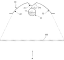
- the acrylic plate 200 is illuminated by the light of each LED element 11.
- unevenness in the illuminance of light irradiated on the acrylic plate is reduced, and the amount of light irradiated on the back surface of the acrylic plate 200 can be effectively improved.
- the uneven brightness of the acrylic plate when the acrylic plate is viewed from the A direction can be reduced, and the acrylic plate can be made bright.
- a plurality of fluorescent tubes 31 extending in a predetermined direction, a plurality of reflecting plates 40 respectively provided on the back side of the plurality of fluorescent tubes 31, and a plurality of fluorescent tubes It is possible to configure a liquid crystal backlight including a diffusion plate 300 provided in front of the tube 31 (eighteenth embodiment). In this case, it is possible to effectively improve the luminance of the liquid crystal and reduce the power used for the backlight for the liquid crystal.
Abstract
L'invention concerne un dispositif d'éclairage dans lequel un élément DEL (11) est disposé de sorte que l'axe optique soit orienté linéairement, une première surface réfléchissante (21) est disposée au-dessus de l'élément DEL, et une ligne saillante (21b) de la première surface réfléchissante (21) dépasse vers le bas. La première surface réfléchissante (21) est en outre disposée dans l'espace entre deux secondes surfaces réfléchissantes (22), et la lumière réfléchie par la première surface réfléchissante (21) est à nouveau réfléchie par les secondes surfaces réfléchissantes (22). La lumière provenant des éléments DEL (11) non réfléchie par la première surface réfléchissante (21) est réfléchie par la seconde surface réfléchissante, et la lumière non réfléchie par la seconde surface réfléchissante (22) est envoyée vers une position d'éclairage sur le sol, d'une pièce par exemple.
Applications Claiming Priority (4)
| Application Number | Priority Date | Filing Date | Title |
|---|---|---|---|
| JP2011-001693 | 2011-01-07 | ||
| JP2011001693 | 2011-01-07 | ||
| JP2011083898A JP2012156123A (ja) | 2011-01-07 | 2011-04-05 | 照明装置 |
| JP2011-083898 | 2011-04-05 |
Publications (1)
| Publication Number | Publication Date |
|---|---|
| WO2012093734A1 true WO2012093734A1 (fr) | 2012-07-12 |
Family
ID=46457583
Family Applications (1)
| Application Number | Title | Priority Date | Filing Date |
|---|---|---|---|
| PCT/JP2012/050230 WO2012093734A1 (fr) | 2011-01-07 | 2012-01-10 | Dispositif d'éclairage |
Country Status (2)
| Country | Link |
|---|---|
| JP (1) | JP2012156123A (fr) |
| WO (1) | WO2012093734A1 (fr) |
Cited By (2)
| Publication number | Priority date | Publication date | Assignee | Title |
|---|---|---|---|---|
| JP2018055807A (ja) * | 2016-09-26 | 2018-04-05 | 株式会社キルトプランニングオフィス | 照明装置 |
| CN113606558A (zh) * | 2021-07-12 | 2021-11-05 | 宁波公牛光电科技有限公司 | 光学结构和灯结构 |
Families Citing this family (1)
| Publication number | Priority date | Publication date | Assignee | Title |
|---|---|---|---|---|
| JP6135009B2 (ja) * | 2013-03-25 | 2017-05-31 | パナソニックIpマネジメント株式会社 | 照明器具 |
Citations (10)
| Publication number | Priority date | Publication date | Assignee | Title |
|---|---|---|---|---|
| JPS577006A (en) * | 1980-06-14 | 1982-01-14 | Matsushita Electric Works Ltd | Reflecting shade for illuminator |
| JPH02155104A (ja) * | 1988-12-07 | 1990-06-14 | Bridgestone Corp | 照明装置 |
| JPH0757523A (ja) * | 1993-08-13 | 1995-03-03 | Matsushita Electric Works Ltd | 水回り空間に設置される間接照明装置 |
| JPH087622A (ja) * | 1994-06-22 | 1996-01-12 | Matsushita Electric Works Ltd | 壁面照明用器具 |
| JP3048914U (ja) * | 1997-07-23 | 1998-05-29 | 株式会社エー・アイ・ジャパン | 天井用照明器具 |
| JP3101220U (ja) * | 2003-10-24 | 2004-06-10 | 三和企業股▲ふん▼有限公司 | 光線に逆らうタイプの光線案内板 |
| JP2006049007A (ja) * | 2004-08-02 | 2006-02-16 | Akira Kondo | ランプ |
| JP3151501U (ja) * | 2008-12-22 | 2009-06-25 | 馨意科技股▲分▼有限公司 | 発光ダイオード灯管の構造 |
| JP2010153078A (ja) * | 2008-12-24 | 2010-07-08 | Nippon Signal Co Ltd:The | Led照明灯及び製造方法 |
| JP2010244835A (ja) * | 2009-04-06 | 2010-10-28 | Nippon Glasstronics Co Ltd | 照明ランプ装置 |
-
2011
- 2011-04-05 JP JP2011083898A patent/JP2012156123A/ja not_active Withdrawn
-
2012
- 2012-01-10 WO PCT/JP2012/050230 patent/WO2012093734A1/fr active Application Filing
Patent Citations (10)
| Publication number | Priority date | Publication date | Assignee | Title |
|---|---|---|---|---|
| JPS577006A (en) * | 1980-06-14 | 1982-01-14 | Matsushita Electric Works Ltd | Reflecting shade for illuminator |
| JPH02155104A (ja) * | 1988-12-07 | 1990-06-14 | Bridgestone Corp | 照明装置 |
| JPH0757523A (ja) * | 1993-08-13 | 1995-03-03 | Matsushita Electric Works Ltd | 水回り空間に設置される間接照明装置 |
| JPH087622A (ja) * | 1994-06-22 | 1996-01-12 | Matsushita Electric Works Ltd | 壁面照明用器具 |
| JP3048914U (ja) * | 1997-07-23 | 1998-05-29 | 株式会社エー・アイ・ジャパン | 天井用照明器具 |
| JP3101220U (ja) * | 2003-10-24 | 2004-06-10 | 三和企業股▲ふん▼有限公司 | 光線に逆らうタイプの光線案内板 |
| JP2006049007A (ja) * | 2004-08-02 | 2006-02-16 | Akira Kondo | ランプ |
| JP3151501U (ja) * | 2008-12-22 | 2009-06-25 | 馨意科技股▲分▼有限公司 | 発光ダイオード灯管の構造 |
| JP2010153078A (ja) * | 2008-12-24 | 2010-07-08 | Nippon Signal Co Ltd:The | Led照明灯及び製造方法 |
| JP2010244835A (ja) * | 2009-04-06 | 2010-10-28 | Nippon Glasstronics Co Ltd | 照明ランプ装置 |
Cited By (2)
| Publication number | Priority date | Publication date | Assignee | Title |
|---|---|---|---|---|
| JP2018055807A (ja) * | 2016-09-26 | 2018-04-05 | 株式会社キルトプランニングオフィス | 照明装置 |
| CN113606558A (zh) * | 2021-07-12 | 2021-11-05 | 宁波公牛光电科技有限公司 | 光学结构和灯结构 |
Also Published As
| Publication number | Publication date |
|---|---|
| JP2012156123A (ja) | 2012-08-16 |
Similar Documents
| Publication | Publication Date | Title |
|---|---|---|
| TWI418737B (zh) | 燈罩及燈具結構 | |
| JP3165544U (ja) | Ledランプのランプカバー | |
| US8297797B2 (en) | Lighting apparatus | |
| KR100931266B1 (ko) | 넓고 균일한 배광을 가지는 실내용 led 조명 | |
| JP6222445B2 (ja) | 照明装置 | |
| KR101062839B1 (ko) | 넓고 균일한 배광을 가지는 led 조명 | |
| US20110096565A1 (en) | Light source apparatus | |
| US20130182430A1 (en) | Planar LED Lighting Apparatus | |
| KR101115394B1 (ko) | 조명장치 | |
| US20220082229A1 (en) | Anti-Glare Lamp and Lighting Arrangement Method Using the Lamp | |
| JP5577209B2 (ja) | 照明装置 | |
| JP2012182117A (ja) | 管型照明器具、管型照明器具用筐体及び両面内照式看板装置 | |
| KR200464527Y1 (ko) | 엘이디등기구용 엠보싱 반사갓 | |
| JP5042173B2 (ja) | 均一な光分布を有する省エネ型ランプシェード | |
| WO2012093734A1 (fr) | Dispositif d'éclairage | |
| WO2012037776A1 (fr) | Ampoule de plaque guide de lumière à del et procédé de fabrication de celle-ci | |
| JP6292509B2 (ja) | 照明装置 | |
| KR100913428B1 (ko) | 반사면 확대로 반사효율이 개선된 형광등기구 및 그 제조방법 | |
| JP2007294252A (ja) | 発光パネル並びに照明器具及び電照パネル | |
| CN201672445U (zh) | 一种反射体以及应用该反射体的反射罩和灯具 | |
| CN214580892U (zh) | 一种双曲面透镜及led灯具 | |
| CN205480327U (zh) | 一种具有反光涂层的led日光灯 | |
| CN202040632U (zh) | 一种led平面光源装置 | |
| EP3521693B1 (fr) | Abat-jour de diffusion de lumière et lampe à panneau le comportant | |
| JP3139278U (ja) | 照明器具およびそれを使用した照明装置 |
Legal Events
| Date | Code | Title | Description |
|---|---|---|---|
| 121 | Ep: the epo has been informed by wipo that ep was designated in this application |
Ref document number: 12732503 Country of ref document: EP Kind code of ref document: A1 |
|
| DPE1 | Request for preliminary examination filed after expiration of 19th month from priority date (pct application filed from 20040101) | ||
| NENP | Non-entry into the national phase |
Ref country code: DE |
|
| 122 | Ep: pct application non-entry in european phase |
Ref document number: 12732503 Country of ref document: EP Kind code of ref document: A1 |